the influence of frequency upon the self-inductance of coils · 276 bulletinofthebureauofstandards....
TRANSCRIPT
THE INFLUENCE OF FREQUENCY UPON THE SELF-INDUCTANCE OF COILS
By J. G. Coffin, Clark University, Worcester, Mass.
When currents of low frequency pass through the wires of a coil,
the current distributes itself uniformly over the cross sections of the
wires. With increasing frequency, this uniform current density no
longer prevails, but, as is well known, at least for straight wires,
the current density becomes greater at the surface of the wire at the
expense of that of the interior.
The corresponding lines of magnetic force become differently
distributed, and in consequence the self-inductance suffers a change.
A short calculation will show the direction and amount of the
change for circuits in which the curvature of the wire may be
assumed negligible, and the theory derived for straight wires used.
The theory of this distribution of the current density in straight
wires, which has been thoroughly worked out by Lord Rayleigh 1
and by Stefan, 2is not applicable without modification to the distri-
bution of current density in coils of wire.
The following argument shows that the effect of increasing fre-
quency is to diminish self-inductance.
We shall assume, according to the theory, that with very high
frequency the current flows entirely in the surface of the conductor.
In computing the mutual inductance between two parallel circuits,
we call their distance apart the logarithmic mean distance of the
area of one cross section from the other. For circular areas, and
circular lines, when completely outside one another, these distances
are the same and equal to the distance between their centers. This
1 Phil. Mag., 21, p. 381; 1886. 2 Wied. Ann., 41, p. 400; 1890.
275
276 Bulletin ofthe Bureau ofStandards. Woi. 2, No. 2.
is also true for annular areas between any two concentric circles,
that is to say, circular rings. When computing the self-inductance
of a circle of circular cross section (solid tore), we use the value of
the logarithmic mean distance r— 0.7788 times the radius of cross
section; but in computing the self-inductance of a circular tube
(hollow tore), we must use for r the radius of the cross section.
To compute the self-inductance of n turns of wire, knowing the
mutual inductances Mrs between each pair of turns, and the self-
inductance L of each turn, we proceed by the following formula
:
Ln= nL+2(n-i)M12+z(n-2)Mls+ +2Mln (1)
The deduction of this formula is an extension of the formula of the
self-inductance of two equal coils in series
:
L2=L+2M12+L
Hence, it is evident that however the frequency of oscillation maychange, the mutual inductance between pairs of wires remains
absolutely unchanged, while any change which does occur is due to
that of the terms involving self-inductance only.
This difference is therefore n times the difference between the
mutual inductance of two circular filaments when placed at a dis-
tance apart equal to 0.7788 X radius of the cross section of the wire
used, and when placed at a distance apart equal to the radius. For
these are the factors used in computing the self-inductance of a
turn for low and high frequencies, respectively. Thus, it is easily
seen that since in the last case the self-inductance is less than in the
first the influence of rapidly oscillating currents is to diminish the
coefficient of self-inductance.
Calculations show that this difference is not negligible, so that in
accurate work it is necessary to make a correction to the value calcu-
lated for low frequencies ;this correction being a function of the
frequency, the conductivity of the wire, the permeability of the
materials of the coil, and of its configuration.
2. Lord Rayleigh has shown 3that for a straight conductor
traversed by sinusoidal currents, the resistance and self-inductance
3 L,oc. cit. See also Gray, Absolute Measurements in Electricity and Magnetism,
Vol. 2, part I, p. 325 ff.

coffin.] Influence ofFrequency on Self-Inductance. 277
for any frequency are given by the following expressions in infinite
series:
R>=r\i +-B* *-i?4+ 1( 12 180
J
and (2)
where B=^-w ,KR is the resistance for steady currents,
fx is the magnetic permeability of the conductor,
/ is the length of conductor,
&) is 27r x frequency of the current.
A is determined from the following formula for the self-induct-
ance for currents of low frequency:
L=l{A+l,x),
R— 5, the resistance for steady currents,Trap
2 ' J '
where p is the radius of the wire and a is the specific conductivity
of the wire.
When the frequency is great, or rather when the product of p, by
the frequency is great, these expressions reduce to
R'= wp/coR
and L' = l(A+ (3)
For any frequency we can calculate the apparent resistance of the
wire, and also the new value of the self-inductance, thus obtaining
an estimate of the variation in self-inductance and resistance with
any required frequency.
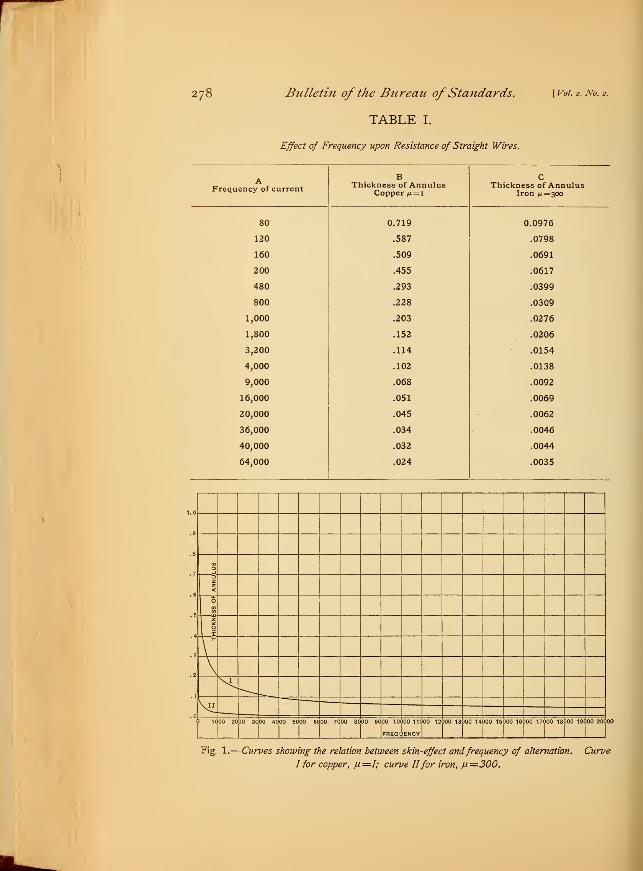
Calculations were made of this so-called skin effect with the fol-
lowing results
:
278 Bulletin of the Bureau ofStandards. [Voi. 2,No. 2 .
TABLE I.
Effect of Frequency upon Resistance of Straight Wires.
AFrequency of current
BThickness of Annulus
Copper fx= i
CThickness of Annulus
Iron ju.=3oo
80 0.719 0.0976
120 .587 .0798
160 .509 .0691
200 .455 .0617
480 .293 .0399
800 .228 .0309
1,000 .203 .0276
1,800 .152 .0206
3,200 .114 .0154
4,000 .102 .0138
9,000 .068 .0092
16,000 .051 .0069
20,000 .045 .0062
36,000 .034 .0046
40,000 .032 .0044
64,000 .024 .0035
.7
.6
.5
.4
D_l
Z
<
O
to_u
I
N\I
\II.0
1 1000 20 00 30 30 4-000 50 00 60 00 70 00 8C 00 9C 00 10
FREQL
)00 11C
JENCY
00 12 300 13 )00 14 300 15 300 16 300 17 300 18 300 19 300 20C 00
Fig. 1.
—
Curves showing the relation between skin-effect andfrequency of alternation. Curve
I for copper, /i—I; curve IIfor iron, fi—300.
coffin.] Influence ofFrequency on Self-Inductance. 279
The interpretation of Table I is as follows: As the frequency
increases so does the resistance. Take a solid wire of any radius,
and for a given frequency construct a hollow wire with the same
external diameter, which would have the same resistance for steady
currents as the apparent resistance of the solid one for alternating
currents. Columns B and C give the ratios of the thicknesses of
such hollow cylinders to the radius, for copper and iron, respectively.
Fig. 1 gives a graphical representation of these values. Theabscissas represent the frequencies. It is seen how readily the cur-
rent betakes itself to the surface of the conductor, so to speak. It
shows that when the material is magnetic, a frequency of 1,000
gives a value of the inductance not appreciably different from fre-
quencies of many times that amount. For copper this correspond-
ing point is not reached before frequencies of 4,000 to 10,000, in the
case for which these calculations were made.
3. The value of the self inductance for low frequency currents for
a length of wire / is
A/=/(4+U) (4)
and the value for very high frequencies is shown by eq. (3) to be
Z-=M = 3/(lQg*/-l) (5)
so that the difference is y2 I ft; this difference is therefore directly
proportional to ft. The coefficient of self-inductance of a straight
conductor of circular cross section is given by
£=2/jlog--(i + log 0.7788)
where p is the radius of the cross section of the conductor ; which
reduces to
z=4ogH} (6)
In the theory of the logarithmic mean distance, it is proved
that the coefficient of self-inductance of any straight conductor of
any cross section is equal to the coefficient of mutual inductance of
two parallel straight filaments, at a distance apart equal to the

280 Bulletin of the Bureau ofStandards. [voi. 2,No. 2 .
logarithmic mean distance of the cross section of this conductor
from itself. For coils, the assumption is made that when the dimen-
sions of the conductor are small in comparison with the radius of
the coil, this law still holds.
Max Wien 4 has shown that this assumption is very close to the
truth, by the following example:
By integration of Maxwell's series for the mutual inductance
between two parallel circles, over a circular cross section, that is by
integration of
1 80/,M—\ira log — I 1+x x2+3v2 xz+$xy*2a 16a2 32a3
where the radii of the two circles are a and a+xyand where y is the
distance between their planes, and r the shortest distance between
them, he obtains the following formula for the self-inductance of a
circular coil of circular cross section:
£=4«{(i+£) ^g ^-1.75-0.0083^} (8)
where p is the radius of the cross section of the wires and a is the
mean radius of the coil. By employing the same number of terms
of the series (7), and putting for y in the series 0.7788 times r he
obtains, without integration, the following formula:
Z= 4™{(i+^) log ^-1.75-0.0095^} (9)
Assuming, now, such dimensions that /?, the radius of the circular
cross section of the wires is equal to one-fourth the mean radius a,
the difference between the two values of Z, computed by these for-
mulas, is less than one part in a thousand. This is a severe test, as,
in the application of the theory of the logarithmic mean distance,
the dimensions of the cross section are assumed to be small in com-
parison with the mean radius. So that, in the use of this principle,
4 Ann. d. Phys. und Chem., 53, p. 928; 1894.
Coffin.] Influence ofFrequency on Self-Inductance. 281
we need not have the slightest fear of inaccuracy if the dimensions
satisfy the above condition.
For example, in the application of the principle to the standard
coil at Clark University, the difference between the two formulas is
given bv
47m {.00000437}
which is negligible, producing a difference only in the eighth place
of significant figures.
4. Using the first terms of Maxwell's series, i. e., neglecting
ysquares of the ratio - we obtain for the mutual inductance of two
circles of the same radius at a distance y apart, the expression
^=47m|log -^-2j
Consider all coils to be wound in the form of a circle, and let the
adjective applied refer to the form of the cross section. Then, for
a solid circular coil, using the principle of the logarithmic meandistance
and for a circular tube
L= 47mJ
log y-1.75J
Z= 47mjlog^-2|
Their difference is 7nz, so that the self-inductance of a single turn
of wire and approximately of any coil of wire, diminishes by an
amount numerically equal to half the length of the wire as the
freque7icy becomes infinitely great. The following computation
shows the amount of this decrease for the Clark University coil
:
Putting a — 27.09 cm
2r— .0584 cm
the difference ita in the self-inductance of one turn is 85 cm in
2,434 cm or about 3.5 per cent of the value for steady currents.
Now, in any coil the mutual inductances between turns are inde-
pendent of the distribution of the currents in the separate wires, as
282 Bulletin ofthe Bureau ofStandards. \_voi. 2,No. 2 .
long as this distribution is symmetrical with respect to the axes of
the wires ; and that is here assumed. The total self-inductance of
the coil in question is about 0.2162 times io9 cm, and there are 716
turns. Hence, the total change for infinite frequency will be 716
times 85, or 60860 cm, which is about 0.286 per cent of the total
value. This certainly is not negligible. It is necessary, then, to
look more closely into this source of error.
Lord Rayleigh 5 and J. Stefan 6 have worked out the theory of
this effect for straight wires, and have deduced formulae showing
the increase in resistance and the decrease in self-inductance with
frequency. Later observers have assumed the effect to be the same
in coils as for straight wires. This is not legitimate, as is clearly
shown by Max Wien. 7 In his paper he shows that the tendency of
the current is to concentrate itself upon the inside surface of the
coil, and he derives two formulae for the increase of resistance and
the decrease in self-inductance in circular coils of single and also of
many layers, wound with wires of circular cross section.
These formulae, however, come out as series which converge only
for small values of the frequency. The formula for the decrease in
self-inductance has but one term derived, and the calculation of the
others seems to be very laborious. It is evident from this paper,
then, that the maximum change in self-inductance, for a coil of a
single layer, is equal to that which would be produced by decreas-
ing the radius of the coil by an amount equal to the radius of the
wire used in winding the coil.
Taking the numerical values for the mean radius and radius of
the wire used above, and multiplying the coefficient ^r— =0.00491
by afo:= 0.0602 cm, we obtain 0.0003 henry as the total possible
change in an inductance of 0.088 henry. This is about 0.34 per
5 L,oc. cit.
6 Ann. d. Phys., 14, p. 1; 1904.
7 The coefficient — was derived by direct calculation for the standard coil con-da:
structed for Clark University, by the writer.
The self-inductance was computed for a mean radius a, and then for a mean radius
a-\-da; the difference gave of course the value of dL for a radius a; dividing by da,
the rate of change of L with respect to a was obtained. See Bulletin of the Bureau
of Standards, Vol. 2, No. 1.

Coffin.] Influence ofFrequency on Self-Inductance. 283
cent of the total amount and is certainly not negligible. This
number compares very favorably with 0.29 per cent derived by
an entirely different process.
The formulae derived by Wien for a coil of a single layer are as
follows:
r' =#{1+0.272 «y- 1
and
where
L'-MHf-)-w }(10)
R' is the resistance at frequency27T
27T
R is the resistance at frequency o,
L' is the self-inductance at frequency
c is the length of coil,
p is the radius of wire,
cr is the specific resistance,
m is the total number of terms,
r is the radius of coil,
r is a small constant,
a) is 27r X frequency,
<b equals —"—
.
crc
The first important result of this calculation is that the increase
of resistance is thirty-two times as large for coiled wire as it is for
the same length of straight wire. This shows the danger of using
without modification, for coils of wire, the results of Lord Rayleigh
for straight wires.
We should expect a corresponding difference for the change in
self-inductance, but from his results this is not possible to verify, as
he was principally interested in the change of resistance. Wien's
calculations agree very well with the experiments of Dolezalek 8 on
the change of resistance for small frequencies.
The next successful attempt to find the change of resistance with
frequency was made by A. Sommerfeld, 9 who derived an expression
8 F. Dolezalek: Ann. d. Phys., 12, p. 1142; 1903.9 A. Sommerfeld: Ann. d. Phys., 15, p. 673; 1904.
284 Bulletin of the Bureau ofStandards. [ Vol. 2, No. 2.
valid for all frequencies and which for small frequencies reduced to
that of Max Wien. He also was principally interested in the change
of resistance, so that the application of his method
to the variation in self-inductance was left untried.
In the following will be found the derivation
of a formula by a method based on that of Sommer-feld, valid for all frequencies, showing the change
in self-inductance with the frequency. By means
of this we shall be able to calculate the correction
to be applied to any coil of a single layer.
5. Derivation of the Formula.—Consider an in-
finite circular current sheet of thickness d, inside
radius rlyand outside radius r
2.
Let the symbols S( ) and V
( )denote the
scalar and vector products respectively. V is the Hamiltonian
operator. V V ( ) is the same as curl( )
or rot. ( ), while S
V ( ) is the same as div.( ).
By symmetry, the field inside the coil is axial, and a function of
r alone, at any given time, and on account of the coil being infinite
in length, the field is all inside of it.
In the dielectric, Maxwell's equations are, if we neglect the dis-
placement current,
z1
>d
h\H *
I h 2
hf
*
I
—
. ! :
Fig. 2.
V\yH=o and $\?H=o. n)
From the second relation we find that H is independent of 2, and
from the first relation, that it is independent of x and y; hence it is
constant inside the coil, and for
r<rxassume H=H eiuit
(12)
where co is 27rX frequency, and H the maximum value of H.
Outside the coil, H must be constant, but as it vanishes at infinity
it is zero everywhere. Hence, for
r>r2 , H- O.

Coffin.] Influence ofFrequency on Self-Inductance. 285
In the material of the coil, Maxwell's equations are
J TT
4tt^ = Vv//, ~j-= —V^/F Sindq= aF (13)
from which follow
Sy^=o, and Sv^= o. (14)
where
q is the current density
.Fis the electric force
a is the specific conductivity.
Eliminating q and F, by taking the curl of the first equation (13)
47rVv<7=VvVv//=vSv//-vV/
— vW,by(i 4),
and from the second and third of (13)
VW= aY\yF= — a-—-dt
•'•4^=v^ (15)
Now assume H in the material of the coil to be given by a function
of r alone (on account of symmetry), multiplied by Hoei0it
, or
where U— 1 when r—rx
U=o " r=rz
The differential equation then which £/must satisfy becomes by
equation (15) in polar coordinates
d 2U 1 dU . , %TT . r .
l^+r^+kU=° (l6
)
where k——i \ttgw.
The solutions of this equation are the Bessel's functions of order
zero, yoand K^ and
H=H,{AJlkr)+BKlkr)Y>* (17)
where A and B are arbitrarv constants.

286 Bulletin of the Bureau ofStandards. \_voi. 2, no. 2 .
Now, Sommerfeld 10 has shown that the expression
Vr gik(rs—r) e ik(r2—r)
r ettM-n)_ e-ik(r2-n)^ \^°)
is a very good approximation formula for the case in which krxand
kr%are large.
Since
TT_ TT dH^irq — ^^jH-
dr
we obtain for the total current / per unit of length the value
'-^;r-U^-U"--"-)\ I:
Hn
47TiV
where N is the number of turns per unit length of the coil.
6. The electrokinetic energy of a system is given by
(19)
(20)
T=-LP2
(21)
where L is its self-inductance, and / is the current. In the case of
alternating currents, the mean square values are meant, or
Hence we may write
Z=^_/joTdt
7i\ rpdt
(22)
where r is the period.
But the mean square value of an harmonic function is one-half the
square of its amplitude, and in working with imaginary expressions
the square of the amplitude can always be obtained by multiplying
any expression by its conjugate.
Loc. cit., p. 678.
ioffin.-\ Influence ofFrequency on SelfInductance. 287
Hence
T'=\^Pdt=\II (23)
where / denotes the conjugate to /.
Therefore
P=\I 1=
and
Z= 414-kN
\h7
\41rN)
JiJV^. (24)
In general 7"=| I j H %dv if /jl= 1 everywhere, (25)
which in this case becomes, for unit length of coil,
T=^ f °IPT.irrdr
or, T=i £nH 2rdr+l C*IPrdr= Tx+ T% (26)
Jo Jn
where, in T„ H is H eiuit
and in 7^, //is given by equation (18).
We may write
I fT
Tdt= l f rdr\ rH2dt= ± fHHrdr.
mFor T, this becomes
To obtain the integral T2first put in eq. (18) h (i-\-t) for ik.
Then, calling h (rz—r)=y,
and h (r2— r±) =yt
we obtain for //and its conjugate //the expressions:
^/ retyieyl— e-iyie-yl
°
and (28)
Y re~ l^eyi— e^xe'^x
29572—06 9

288 Bulletin ofthe Bureau ofStandards. [Vol. 2, m. 2.
A conjugate expression is obtained by putting — i for i every-
where in the equation.
Their product becomes
or
rxcosh 2_y— cos 2yHH=H«
rcosh 2jKi— cos 2yx
Multiplying this expression by rdr and integrating from rxto r
% gives
(since I coshr^r=sinhr)
putting x— 2h (r2— r
x)= 2hd,
_H*r1d'sinh x— sin x
2_8 .r cosh x— cos
#"
We may now write
Z. W2 4i
2 ^/3 s^nh -^— sin^\)1
J ""^^yrcosh .r— cos .r/J ^°/
where .r= 2d-yj2tt(D(t= (47r<3\/cr)
V
;* where ^—2 rJrn.
Now, 47rW2r1
2is the self-inductance per unit length of a coil with
a mean radius r1}
and is therefore the self-inductance for infinite
frequency. This is also shown by eq. (29) as the second term in
sinh xparenthesis is zero when ^=00 for
—
-,—= 1 and sinh x and cosh xcosh x
increase without limit as x increases without limit, as may be seen
by their expansions
:
(30)
sin hx-. xs x5
.
. . . . ; sin X— X-x3 xb
cos hx-=*+i+$+ - . . . ; cos x= 1 -x2
X*_
2!+
4!
Equation (29) may then be written
L<*~K^ d(
^sinh^r--sin x\\=
2 *Q. (31)

coffin.] Influence ofFrequency on Self-Inductance, 289
By this equation we see that the fractional change of self-inductance
in any coil may be calculated if the properties of the function
g_ 3 sinh^-sin^ ,„\x cosh x— cos x ^ '
be known for all values of x from zero to infinity.
A formula for small frequencies may be derived by expanding the
hyperbolic and circular functions and retaining only low powers of
the variable x. Q then becomes
1 x^ xs
I X* X°+ • • •2M 6!^io!
which, retaining only terms in x^ is
1 3^4
6jt4
2 '7! i+ 7-z*,6^4 14^* 8X* x^O— '- — —
-
—= 1 4- — _n_ — 1— — 1 —^ I X^ I-J-2.T4
7! 7! 7! 630.
2+ 6! 6T
This equation is applicable for small frequencies only, and (31) maybe written, since 64.Tr
2= 630 very approximately,
A,-Ao _2 *^i-^ (33)
It agrees as to form and dimensions with that of Max Wien, eq. (10).
2 d ' 2dWhen (o= o. it reduces to As a verification of the term —
,
3 rv 3 ri
the approximation formula for Bessel's formula with small argument
H=HJrir^-^eM (34)
V r r*~ r\
was taken and a calculation similar to the one above was made for
the general case. This completely verified this term, and proved
that the expression used above, eq. (31), is valid for small arguments

290 Bulletin of the Bureait ofStandards. [ Vol. 2, No. 2.
2das well as large. This last expression— multiplied by Z
o
477-WV! 2is
Ln-L °ir*N %r1d
3(35)
and is therefore the additional self-inductance due to the field in the
wires themselves for steady values of the current, or, in other words,
this is the maximum possible change in self-inductance. Calcula-
tions by means of (35) show this expression to give, for coils of
finite length and wires with round instead of square cross sections,
the following values
:
TABLE II.
Comparison of the Theoretical with the True Change in Self-Inductance.
Coil Length True Change Value of? -3 ri
Ratio
46.0 cm.
30.5 "
15.0 "
13.0 "
.00038 henry
.00020 "
.000067 "
.000051 "
.00028 henry
.00016 "
.000057 "
.000044 "
1.35
1.25
1.17
1.16
The values in the second column were computed by taking the
difference between the self-inductance of a coil of mean radius #,
computed by means of an exact formula, and that of the same coil,
using as a mean radius a— p, where p is the radius of the wire.
These results, considering the assumptions made in the theory, are
in good agreement with it. To make the theory fit the facts, the
second term in the parenthesis in equation (29) should be multiplied
by a constant, the average value of which is approximately 1.25,
deduced from the above table. We should expect some multiplier
to be necessary because a current sheet is the equivalent of square
wires without insulation, while, in any actual coil, the wires are
round and have insulation. We may then write
2 d/3 sinh^:— sin x\
3 r\x cosn x— cos x) (36)

coffin.] Influence ofFrequency on Selfllnducta?ice. 291
In the proposed use of this theory, however, it is not necessary to
employ this constant, whose value at best is not satisfactorily deter-
minate.
As cosh x and sinh x increase without limit as x increases, equa-
tion (36) may be written, for large values of co
Ac ° rxx 4 r
xd^2 iT(D(T
K6J)
This formula agrees to within a constant factor with that of Lord
Rayleigh for large values of n)equation (3),
°r —7 =J—r=2^00 V 211I d-y]Zttcoo-'
Computations were carefully made for the values of the term
3 sinh x— sin x (38)^—x cosh x— cos x
for the different values of x)as well as of Qx
and Q2where
Gi=I-S^ (39)
a=£ (40)
Table III contains the results.
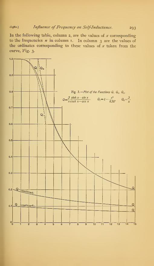
It is clearly seen that as long asx< 2 formula Qxmay be used, while
if ^>7, formula Q2is valid. Between these points the calculated
values will serve.
A plot of these three curves shows still more clearly the relations
of the three formulae for different values of x. (See Fig. 3.)
7. Manner ofUsing the Curve.—This curve is to be used in the fol-
lowing manner. We assume that in any coil of a single layer the fall-
ing off of the self-inductance takes place according to equation (32),
represented by the full line curve, and the maximum ordinate unity
is taken to be the maximum possible change of the self-inductance,
which may be calculated. For any given dimensions of the coil the

292 Bulletin of the Bureau ofStandards. [voi. 2,No. 2.
TABLE III.
Values for the Curves Q, Qv and Q2 for Values of x from to 00
.
X cosh x sinh x COS X sin x Q Qi Q 2
0.0 1.0000 0.0000 1.0000 0.0000 1.0000 1.0000 00
0.5 1.1276 0.5211 0.8776 0.4789 0.9999 0.9999 6.0000
1.0 1.5431 1.1752 0.5402 0.8415 0.9984 0.9984 3.0000
1.5 2.3523 2.1291 0.0706 0.9975 0.9920 0.9918 2.0000
2.0 3.7622 3.6269 —0.4163 0.9092 0.9756 0.973 1.5000
3.0 10.0677 10.0178 —0.9900 0.1409 0.8932 0.871 1.0000
4.0 27.308 27.262 —0.6534 —0.7570 0.7515 0.594 0.7500
5.0 74.204 74.197 + 0.2840 —0.9588 0.6100 Negative 0.6000
6.0 202.approx. 202.approx. 0.9603 —0.2790 0.5032 it 0.5000
7.0 573.approx. 573.approx. 0.7537 0.6574 0.4287 tt 0.4289
8.0 Very large
and the
same as
sinh x
0.3750 « 0.3750
9.0 0.3333
0.3000
<<
CI
0.3333
10.0 0.3000
00 00 00 Indeter. Indeter. — 00
values of x correspond to definite frequencies, and either a table or
a plot of corrections may be derived from the curve.
For small values of xyand therefore for small values of the fre-
quency, the correction varies proportionately to <^4
,while for very
large frequencies it is proportionate to - by equations (39) and (40).
As the first case is the more usual, it is important, in order to
avoid the necessity for any correction, to wind the coil with wires
of small diameter. The size necessary to avoid a correction under
a given frequency may easily be calculated. As an example of the
employment of this theory, the following example will be carried
out:
Consider a coil of 27 cm radius — rxwound with a single layer of
wire, whose diameter d is 0.063 cm - Let the conductivity of the
wire be taken as 5.9 X io-4 . Then the relation between x and n is,
from (29) where n — frequency,
«= 2630a;2.
coffin^ Influence ofFrequency on Self-Inductance. 293
In the following table, column 2, are the values of x corresponding
to the frequencies n in column 1. In column 3 are the values of
the ordinates corresponding to these values of x taken from the
curve, Fig. 3.
1.U
0.9
0.8
0.7
0.6
5
\q
\
\
\
\
\q 2\
\
Fig. 3.—Plot 0/ the Functions Q, Qlf Q 2 .
_ 3 sink x—sin x n 7 xi ~ 3Q= ; ' k<i— *— ^ .-, W2 == -*
xcosh x—cos x 630' x
\
\ \ t
\ \
\v
\ \\
\ \\ \\ \
\
'
I
\
Q,'1
I
I
\\
Vi
]
\
0.3
Q \Q
0.1Q contm,
Uetf,
Q
n
01 2345678 10 11 12 13 14 15

294 Bulletin ofthe Bureau ofStandards. Woi. 2, No. 2.
TABLE IV.
Values of Frequency n, and Corresponding Values ofx and of Relative Change in Self-Inductance.
n X Ordinate
1.000
500 .44 1.000
1,000 .62 0.999
1,500 .76 0.998
3,000 1.07 0.996
4,000 1.23 0.995
5,000 1.38 0.993
6,000 1.51 0.990
10,000 1.95 0.977
15,000 2.38 0.950
20,000 2.75 0.916
30,000 3.38 0.846
40,000 3.90 0.765
50,000 4.35 0.700
60,000 4.78 0.638
70,000 5.15 0.590
80,000 5.51 0.550
90,000 5.85 0.515
100,000 6.17 0.483
120,000 6.76 0.463
150,000 7.55 0.397
170,000 8.05 0.373
200,000 8.72 0.344
The plot of the corresponding values of n as abscissas and values
of column 3 as ordinates gives a curve of corrections for the above
coil. For example, at a frequency of 50,000 the correction is 0.3
of the maximum change. The value of the correction may be
obtained by reading down from the ordinate unity.
These computations also show that equation (39)
a=i-630

Coffin.-] Inflitence ofFrequency on Self-Inductance. 295
may be employed up to frequencies of 10,000 for this particular coil,
and that equation (40)
&= x
may be used for frequencies beyond 120,000 per second. As the
maximum correction is only 0.2 per cent of the total, if frequen-
cies under 4,000 per second are used, the error will not be over
0.2 per cent X 0.005 = 0.001 per cent, which is practically negligible.
LU <o3
0.
0.
0.
0.
0.
0.
u.
I \
O
<>
<
CO_1_1
2-X-
\
\<-JQ.
<-J OQ.
O -1
z m^ CO \
\
*"CO
UJ 1U
z. z< UJ1 3O O
es s
I
COCO
Q.
_l
1-
IOI
CO
LL
1-
E<
<
10 20 30 40 5
I I I I
60 7
I
1
FREQl
30 1
JENCY
1 »0 130 1
I
40 160 160 1
I
: 180 190 2( 5
Fig. 4.
—
Curve showing the fractional part of the maximum possible decrease in inductance
which takes placefor different frequencies in a coil the wire of which has a diameter of 0.063
cm, the radius of the coil being 27 cm.
If, however, other things being equal, the diameter of the wire
were four times larger than it is, the same corrections would corre-
spond to frequencies 16 times less, or an error of 0.001 per cent
is now obtained at a frequency of only 250.
This suggests that if large currents must be carried, to wind the
coil with, flat wires would diminish the effect of the frequency upon
the changes both in self-inductance and in resistance.

296 Bulletin ofthe Bureau ofStandards. Woi 2, No. 2.]
Figs. 3 and 4 show how the self-inductance of a circular current
sheet falls off with the frequency. In other words, the coil is
assumed to be wound with wires of rectangular cross section. This
may cause a doubt as to the applicability of the curve in question
to the winding of round wires.
In the first place, the method of its use does away with the neces-
sity of knowing the constant multiplier of the function Q, as
explained above; and in the second place, the following two reasons
go to show the entire correctness of the deductions.
Sommerfeld finds that his results agree to within a constant with
those of Max Wien, which were deduced for circular wires, and both
formulae agree remarkably well with the experimental data at hand;
this for the increase of resistance with the frequency. We should
therefore fairly expect the results for the decrease in self-inductance
also to be correct to within a constant factor. As there are no data
available for the decrease in self-inductance, we have not been able
to verify this conclusion. To further assure ourselves, however, wehave worked out the problem of the change of self-inductance with
the frequency in an infinite straight circular ring conductor, using
the approximation formulae for the BessePs functions, as above given.
It was found that the variable part of the expression for self-induc-
tance agreed identically with that derived for a circular current
sheet. This shows that the bending of a straight wire into a circu-
lar shape and forming a coil therewith does not affect the manner
in which the self-inductance changes.
We believe, then, there is no doubt that Fig. 3 gives the law
according to which the self-inductance falls off for straight ring-
shaped conductors and probably for any simply shaped square or
polygonal straight conductors, as well as for circular coils of a single
layer, wound with wires of circular, square, or polygonal cross
sections.