the influence of interface layer on microstructural stresses in mortar
TRANSCRIPT
INTERNATIONAL JOURNAL FOR NUMERICAL A N D ANALYTICAL METHODS IN GEOMECHANICS. VOL. 20, 21 5-228 (1996)
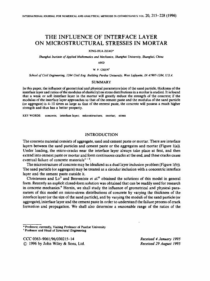
THE INFLUENCE OF INTERFACE LAYER ON MICROSTRUCTURAL STRESSES IN MORTAR
XING-HUA ZHAO.
Shanghai Institute of Applied Mathematics and Mechanics. Shanghai University. Shanghai, China
AND
W. F. CHEN'
School of Civil Engineering, 1284 Civil Eng. Building Purdue Uniwrsity. West hf¥e, IN 47907-1284, U.S.A.
SUMMARY
In this paper, the influence of geometrical and physical parameters (size of the sand particle, thickness of the interface layer and ratios of the modulus of elasticity) on stress distributions in a mortar is studied. It is found that a weak or soft interface layer in the mortar will greatly reduce the strength of the concrete; if the modulus of the interface layer approaches to that of the cement paste and the modulus of the sand particle (or aggregate) is 4-10 times as large as that of the cement paste, the concrete will possess a much higher strength and thus has a better property.
KEY WORDS: concrete; interface layer; microstructurc; mortar, stress
INTRODUCTION The concrete material consists of aggregate, sand and cement paste or mortar. There are interface layers between the sand particles and cement paste or the aggregates and mortar (Figure l(a)). Under loading, the micro-cracks near the interface layer always take place at first, and then extend into cement paste or mortar and form continuous cracks at the end, and these cracks cause eventual failure of concrete materials' -3 .
The microstructure of concrete may be idealized as a dual layer inclusion problem (Figure l(b)). The sand particle (or aggregate) may be treated as a circular inclusion with a concentric interface layer and the cement paste outside it.
Christensen and Lo' and Benveniste et aL6 obtained the solutions of this model in general form. Recently an explicit closed-form solution was obtained that can be readily used for research in concrete mechanics? Herein, we shall study the influence of geometrical and physical para- meters of this model on micro-stress distributions of concrete by varying the thickness of the interface layer (or the size of the sand particle), and by varying the moduli of the sand particle (or aggregate), interface layer and the cement paste in order to understand the failure process of crack formation and propagation. We shall also determine a reasonable range of the ratios of the
* Professor; currently, Visiting Professor of Purdue University ' Professor and Head of Structural Engineering
CCC 0363-9061/96/030215-14 0 1996 by John Wiley & Sons, Ltd.
Received 4 January 1995 Received 29 August 1995

216 SHORT COMMUNICATIONS
modulus of elasticity for the sand particle (or aggregate), interface layer, and the cement paste as well as a proper range of geometrical size of sand particle in order to study and produce new concrete materials with higher strength.
FORMULAS FOR THE STRESSES AND LOAD-CARRYING VALUE
For the calculation model shown in Figure l(b), we denote the elastic constants of the sand particle (or aggregate), cement paste and interface layer as El, pl, E3, p3 and EZ, p2, respectively. Let a be the radius of a sand particle and b the outer radius of the interface layer subjected to a uniaxial tension stress oo at infinity. For formulas for the stresses see Reference 4.
The typical stress distribution of the microstructure is shown in Figure 6. Maximum normal stresses are located at sections of 8 = 0 and 90". A maximum shear stress is at 8 = 45" section.
........... ................. ........... .................. ........... ...........
......................................... ......................................... ......................................... /
Figure 1. The
Interface layer
(a)
model of microstructure of concrete: (a) Details of concrete mass and the magnification portion. (b) The dual layer inclusion problem
of its mortar

SHORT COMMUNICATIONS 217
c-
c-
t 4
E3
- + I + - i t -
(b)
Fig. 1. Continued
Since the cracks of concrete usually take place at these locations, we shall focus our observations primarily on these sections.
For a good concrete mixture, the sand or aggregate should bear the major external load. This leads to a higher strength concrete. At 8 = 90" section, the total force on the sand particle (or aggregate) is
P = r - a 4dr=2a[(L +1)A0_2A;-4B>a2 m a' 1 Thus the ratio P/(2aoa) provides a good indication of the share of external load carried by the
sand particle or aggregate. Higher the value of P/(2aoa), more will be the load carried by the sand or the aggregates. For the values of m, Ao, A; and B; see Reference 4.
THE INFLUENCE OF THE RIGIDITY O F A SAND PARTICLE ON STRESSES IN MICROSTRUCTURE (WITHOUT INTERFACE LAYER)
In the following, we shall first study the special case of no interface layers. We shall vary the modulus El of elasticity of sand from 0 to 00 with p1 = p3 = 0 3 .
The influence of E1/E3 on load-canying values of sand particle
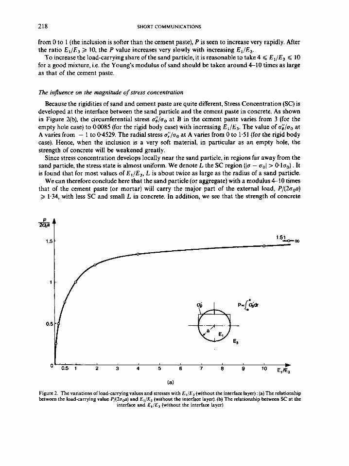
The variation of the loadcarrying value P of a sand particle versus E 1 / E 3 is shown in Figure 2(a). The maximum load-carrying value for a sand particle is found to be only 1.51 times that of the average one, even if the sand is treated as a rigid body (El 4 00 ). As the ratio E1/E3 changes
218 SHORT COMMUNICATIONS
from 0 to 1 (the inclusion is softer than the cement paste), P is seen to increase very rapidly. After the ratio E1/E3 2 10, the P value increases very slowly with increasing E l / E 3 .
To increase the load-carrying share of the sand particle, it is reasonable to take 4 < E l / E J < 10 for a good mixture, i.e. the Young's modulus of sand should be taken around 4-10 times as large as that of the cement paste.
The influence on the magnitude of stress concentration
Because the rigidities of sand and cement paste are quite different, Stress Concentration (SC) is developed at the interface between the sand particle and the cement paste in concrete. As shown in Figure 2(b), the circumferential stress og/ao at B in the cement paste varies from 3 (for the empty hole case) to 0.0085 (for the rigid body case) with increasing E1/E3. The value of oZ/oo at A varies from - 1 to 0-4529. The radial stress a:'/ao at A varies from 0 to 1-51 (for the rigid body case). Hence, when the inclusion is a very soft material, in particular as an empty hole, the strength of concrete will be weakened greatly.
Since stress concentration develops locally near the sand particle, in regions far away from the sand particle, the stress state is almost uniform. We denote L the SC region (lo - ao1 > 0.10~). It is found that for most values of E 1 / E 3 , L is about twice as large as the radius of a sand particle.
We can therefore conclude here that the sand particle (or aggregate) with a modulus 4-10 times that of the cement paste (or mortar) will carry the major part of the external load, P/(200a) 2 1.34, with less SC and small L in concrete. In addition, we see that the strength of concrete
1 1.5
Figure 2. The variations of load-carrying values and stresses with EI/E3 (without the interface layer) : (a) The relationship between the load-carrying value P/(20,0) and El/& (without the interface layer). (b) The relationship between SC at the
interface and E , / E 3 (without the interface layer)

SHORT COMMUNICATIONS 219
-1 I".'-- (b)
Fig. 2. Continued
including the case of hole will be weakened greatly due to SC. The micro-cracks may be formed first at the boundaries of the holes.
THE INFLUENCE O F INTERFACE LAYER ON MICROSTRUCTURAL STRESSES
In concrete materials, there exist very thin interface layers between sands and cement paste. The stresses in microscale will be greatly affected by the existence of the interface layers. In the following, we shall take a = 1, b = 1-05, oo = 1 and p1 = p 2 = p 3 = 0.3 and study the influences of the interface layer systematically.
The injluence of interface layer on load-carrying value of sand particle
with E2/E3 and log(E1/E3) (Figure 3(a)) and find: Now we study the variations of the load-carrying value P of the sand particle (or aggregate)
( 1 ) Due to the presence of the interface layer, P/(2aoa) is rapidly reduced with decreasing E2/E3. When E2/E3 < 0.01, P,,I/200a < 0.374. The ability of concrete to resist applied load will be greatly weakened by the presence of the softer interface layer.

220 SHORT COMMUNICATIONS
(2) When E 2 > E3, i.e. the rigidity of the interface layer is larger than that of the cement paste, the maximum load-carrying value of the sand particle P,,, will be increased only slightly and an excessive increase of E 2 will not contribute much to the strength of concrete.
(3) When E1/E3 = 4-10 ( log (E , /E , ) = 061.0) and E2/E3 = 0.S2.0, the sand particle or the aggregate will carry a higher load value.
The influence of interface layer on stress concentration
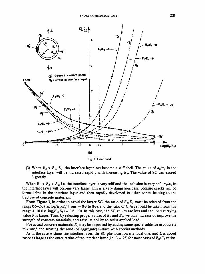
The maximum normal stress occurs at 8 = 90". The variations of the stress ai/ao in the cement paste and the stress oe/ao in the interface layer at t = b with E I / E 3 and l o g ( E 2 / E 3 ) are shown in Figure 3(b). From the figure, we find that the stresses and SC are greatly affected by the presence of the interface layer. The following conclusions can be made:
(1) When E2 < E3, i.e. the interface layer is softer than the cement paste, no matter what the ratios E2/E3 are, a;/ao in the cement paste will be increased rapidly with reducing E2. For the case of E2JE3 < 0.01, aE/ao will be raised over 2.3.
(2) When E3 < E 2 < E l , ai/ao in the cement paste are all less than 1, and ae/oo in the interface layer are generally less than 1. So, the concrete material will possess a higher strength.
t"
i@J . El
E; I €3 1 .o
f & , I E& 4 . 0
* € , I € , =0.08 I I----------- &------ 1
I I
I
-2.0 - 1.0 0.3 0.6
(a)
Figure 3. The variations of load-carrying values and stresses with E J E 3 and E 2 / E 3 (with interface layer) : (a) The load-carrying value P/(Za@) verses EdE3, l o g ( E , / E , ) . (b) At r = b and 0 = 90". the variations of stresses as/ao with El/&
and log(E2/E3)
SHORT COMMUNICAHONS 221
I
SU~MI In cement paste
2.329 4, : Stress m interfece layer
(b)
Fig. 3. Continued
(3) When E2 > El, E3, the interface layer has become a stiff shell. The value of ae/ao in the interface layer will be increased rapidly with increasing E2. The value of SC can exceed 3 greatly.
When El c E3 c E2, i.e. the interface layer is very stiff and the inclusion is very soft, ae/ao in the interface layer will become very large. This is a very dangerous case, because cracks will be formed first in the interface layer and then rapidly developed in other zones, leading to the fracture of concrete materials.
From Figure 3, in order to avoid the larger SC, the ratio of E2/E3 must be selected from the range 0.5-2.0 (i.e. log(E2/E3) from - 0.3 to 0.3), and the ratio of E1/E3 should be taken from the range 4-10 (i.e. log(E,/E,) = 06-1.0). In this case, the SC values are less and the loadcarrying value P is larger. Thus, by selecting proper values of E2 and El, we may increase or improve the strength of concrete materials, and raise its ability to resist applied load.
For actual concrete materials, E 2 may be improved by adding some special additive in concrete mixture? and treating the sand (or aggregate) surface with special methods.
As in the case without the interface layer, the SC phenomenon is a local one, and L is about twice as large as the outer radius of the interface layer (i.e. L = 2b) for most cases of E2/E3 ratios.
222 SHORT COMMUNICATIONS
In addition, we find that when pL1 varies from 0401 to 0.49, all values of P, L/a and SC in the mortar remain essentially the same. Hence, we need not consider the influence of p2 in the interface layer on microstructural stress state.
THE INFLUENCE OF SAND SIZE O N MICROSTRUCTURAL STRESSES
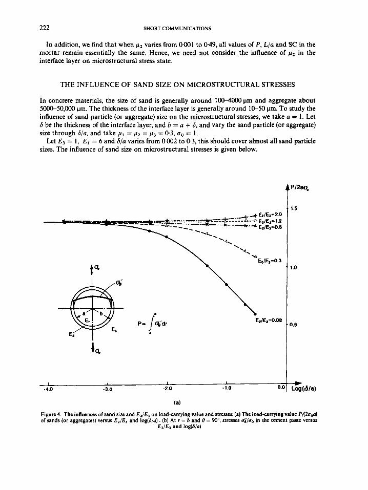
In concrete materials, the size of sand is generally around 1OO-4OOOpm and aggregate about 5oo(r-50,000 pm. The thickness of the interface layer is generally around 10-50 pm. To study the influence of sand particle (or aggregate) size on the microstructural stresses, we take a = 1. Let 6 be the thickness of the interface layer, and b = a + 6, and vary the sand particle (or aggregate) size through 6/a, and take p1 = p2 = p3 = 0.3, no = 1.
Let E3 = 1, El = 6 and b/a varies from 0.002 to 0.3, this should cover almost all sand particle sizes. The influence of sand size on microstructural stresses is given below.
t"
I I I I
-2.0 -1.0 0 .o -4.0 -3.0
(a)
1.5
1 .o
0.5
-w Log(b/a)
Figure 4. The influences of sand sizc and E J E , on loadcarrying value and stresses: (a) The loadcarrying value P/(2u00) of sands (or aggregates) versus E 2 / E 3 and log(@). (b) At r = b and 0 = 90". stresses u;'/uo in the ament paste versus
E 2 / E , and log(d/a)

SHORT COMMUNICATIONS
Epl€,=0.08 /
P / ,' A
-4.0 -3.0 -2.0 -1.0 0.1
(b)
Fig. 4. Continued
223
2.0
1.5
1 .o
0.5
- Log(dla1
The injluence on load-carrying value
Figure 4(a) shows the variation of P/(2aoa) with E 2 / E 3 and log(b/a) . We find:
(1) When E 1 / E 3 = 6 and E 2 approaches E3, i.e. E2/E3 = @8-2.0, regardless of the sand particle or aggregate size, P does not change much. In this case, all values of P/(2aoa) are approxim- ately equal to 1.39, i.e. the influence of sand size on loadcarrying value is very small.
(2) As the aggregate size becomes large (b/a = O-O14*OOO1 or log(b/a) = - 2 to - 4), the influence of the interface layer on the load-carrying value is very small. Thus, for aggregate, we need not consider the variation of the load-carrying value P with its size.
(3) When the interface layer is softer (EJE3 < 03), the smaller the sand size, the larger the influence of the interface layer on P/(2aoa). Moreover, the softer the interface layer, the more the reduction of P/(2aoa). Thus, in order to avoid the decrease of the load-carrying value of the sand particle, we must take E2/E3 > 0.5 in concrete, i.e. the interface layer may not be too soft. For EJE3 = 0.3, to maintain the load-carrying value of sands, the size of the sand particle must be larger than 1500 pm. Due to the influence of the interface layer, the ability to resist load for coarse sands is better than that of fine sands for the case when the interface layer is softer.

224 SHORT COMMUNICATIONS
The injluence on stress concentration
In Figure qb), aP/ao at 0 = n/2, r = b in the cement paste are shown. From figure we can make the following conclusions:
1 .o
Because the aggregate size is generally larger than SO00 pm (6/a as 0014-001 or log(S/a) as - 2 to - 4), when E J E 3 = 6, all the SC values in the mortar are very small and almost constant. Thus, for aggregates we need not consider the influence of their size on SC. Because the size of sand is generally around 100-4000 pm (6/a as 034-0125 or log@/a) as - 0.3 to - 1.9), the influence of sand size on the SC is larger. When the sand size decreases
gradually and the interface layer becomes softer, this influence will become greater and greater. The SC in the cement paste will exceed 1 quickly.
E1=5 , a=1.0
E z = l O , b=1.05
E,=l * C&=l
i I b
i \ I
..
ir II i
k 1 I
-0.692
la (a)
Figure 5. The influence of rigidity of the interface on stress distribution: (a) The stress distribution of microstructure when E l > E , , E,. (b) The stress distributions of microstructure when E,<<E, < E ,

SHORT COMMUNICATIONS
t"
225
E,=5 , aSl.0 [email protected] , b=1.05 E,=l 9 - 1
1 .o
(b)
Fig. 5. Continued
(3) In the case of E I / E 3 = 6, when E 2 value of the interface layer is close to E 3 ( E 2 / E 3 as 0.8-2.0), all SC in the cement paste and the interface layer will be less than 1, and we need not consider the influence of their size on the SC.
In addition, when 6/a < 0.03 (i.e. log(b/a) < - 15), the stresses in the interface layer may be considered practically to be a uniform one. But, as the value of S/a increases, there will exist bending stresses in the interface layer in addition to uniform stresses.
For the E l / & = 6 case, so long as the interface layer is not too soft (E2/E3 > 0*3), the values of L/a is around 2 for various sand sizes.
Thus, when E 1 / E 3 = 6 and E2/E3 = 043-2.0, the influence of the size of the aggregate or sand particle on microstructural stresses is not large. Only when the interface layer is softer ( E 2 / E 3 < 0.5), the less the sand size, the larger the influence. Thus, in the present case, using a finer sand to increase the strength of the concrete has no special advantage.

226 SHORT COMMUNICATIONS
MICROSCOPIC STRESS DISTRIBUTION WITH INTERFACE LAYER
The influences of the rigidity of the interface layer on stress distribution are shown in Figure 5. As E2 varies from very hard (E2 > El, E,) to very soft (E2 < E,, El), ue/ao in the interface layer at 8 = 90" decreases rapidly from a very large value to approximately zero. The SC of the interface layer is very large when E2 is very large. It is a very dangerous case. But, when E2 -+ 0, the interface layer becomes an empty interval at 8 = W, and the SC in the cement paste becomes very large (Figure 3(b)), so it is also a dangerous case.
The stress distributions for the cases when the inclusion is harder and softer are shown in Figure 6. For high-strength concretes, their inclusions are stiffened, so EIIE-3 is very large. Its stress distribution is similar to that of Figure qa). The inclusion can take a major share of load and the stress u, on 8 = 0 section is very large, and stresses on other sections are less. Hence, cracking type of failure will take place first at r = b, 8 = 0, and then develop through the
I I E,=5 , a=1.o &=0.8 , b=1.05 E p l , 4 = 1
i t
4
I I
-0.a Tc'
1 .o
1. *
-0.680
I I
I I
t
i I
I 11.370 -
(a) Figure 6. The influence of rigidity of the inclusion layer on stress distribution: (a) The stress distribution of microstructure
when E 2 = E 3 and E l . E 3 < El. (b) The stress distribution of microstructure when the inclusion is softer

SHORT COMMUNICATIONS 227
(b) Fig. 6. Continued
inclusion. The strength of this concrete is higher due to the fact that the strong inclusion will carry a major portion of the applied load.
For light-weight concretes, their inclusions are weak, so E 1 / E 3 and E2 are smaller. Its stress distribution is similar to that of Figure qb). The maximum stress oF/ao is located in the cement paste at 8 = 90". r = b. The stresses on inclusion are very small. Hence, the cracking will take place first at 8 = 9, r = b, and then will develop along the surface of the inclusion.
CONCLUSIONS
For a sand particle (or aggregate) regardless of its interface layer, it should have a modulus value around 4-10 times that of the cement paste. In this case, the load-carrying value of sand particle P/(2aoa) > 1.34 and the SC in the concrete is smaller.

228 SHORT COMMUNlCATlONS
The interface layer will affect greatly the micromechanical properties of the concrete. They are the weakest zone in the microstructure. To raise the strength of the concrete, we must first improve their properties.
If the interface layer is very soft ( E 2 / E 3 < 05), the load-carrying value of the sand particle will decrease quickly and the SC in the cement paste will increase rapidly as E 2 decreases. The strength of the concrete will be weakened greatly.
If the interface layer is very hard ( E 2 > El, E,) , the stiff shell will form on the surface of the sand particle or aggregate and there will be a very high SC in the interface layer. They can be fractured very easily. There is no advantage to increase the strength of the concrete.
To avoid a higher SC in the cement paste and interface layer and to obtain a larger load-carrying value for sand particle or aggregate, we must take the modulus E 2 of the interface layer approximately to be that of E3 of the cement paste and must make the modulus El of the sand particle or aggregate far more than that of E 2 and E,. In general, we may take Ez = (0-8-2.0) E , and El = (4-10) E3. In this case, the microstructure of the concrete will possess better mechanical properties and higher strength.
For aggregates, in general, we need not consider the influence of the interface layer and their size on their micromechanical properties unless the interface layer is very soft.
When E 1 / E 3 > 4 and E z / E 3 = 0.8-2.0, we may also disregard the influence of the sand size on the microstructural stresses in the concrete. But when E 2 / E 3 < 0.5, the influence of the sand size and the rigidity of the interface layer on microstructural stresses are very large.
The stress concentration phenomenon in the microstructure is a local one. For most cases, the size L of SC region may be taken as L = 26.
Since the thickness of interface layers is very thin, the stresses in them may be regarded as uniform (for most cases) or linear distribution (for thicker case).
In general, the maximum stress in microstructure of concrete is located on 8 = 90" or 8 = 0" section and near (or in) the interface layer. The microcracks usually take place first from the interface.
ACKNOWLEDGEMENTS
This research was supported in part by a grant from the National Science Foundation (MSS- 9202123, Program Director: Dr. K. P. Chong). We thank Professor M. Cohen for providing the data on material properties of concrete.
REFERENCES
1 . W. F. Chen, 'Concrete plasticity: recent developments', A S M E Reprint No. A M R 146, 1994. 2. M. D. Cohen, A. Goldman and W. F. Chen, 'The role of silica fume in mortar: transition zone versus bulk paste
3. E. Yamaguchi and W. F. Chen, 'Microcrack propagation study of concrete under compressive loading'. J . Erg . Mech.
4. Xing-Hua Zhao and W. E. Chen, 'Stress analysis of a sand particle with interface in cement paste under uniaxial
5. R. M. Christensen and K. H. Lo, 'Solutions for effective shear properties in three phase sphere and cylinder models', J .
6. Y. Benveniste, G. J. Dvorak and T. Chen, 'Stress fields in composites with coated inclusions', Mech. Mat., 305317
modification', Cement Concr. Res.. 24, 9S98 (1994).
ASCE, 117,653-673 (1991).
loading', CE-STR-94-23, School of Civil Engineerin& Purdue University, West Lafayette. IN, 1994.
Mech. Phys. Solids, 27, 31S330 (1979).
( 1989).