the influence of temperature on rc beams strengthened with ... · with externally bonded cfrp...
TRANSCRIPT
The influence of temperature on RC beams strengthenedwith externally bonded CFRP reinforcementKlamer, E.L.; Hordijk, D.A.; Hermes, M.C.J.
Published in:Heron
Published: 01/01/2008
Document VersionPublisher’s PDF, also known as Version of Record (includes final page, issue and volume numbers)
Please check the document version of this publication:
• A submitted manuscript is the author's version of the article upon submission and before peer-review. There can be important differencesbetween the submitted version and the official published version of record. People interested in the research are advised to contact theauthor for the final version of the publication, or visit the DOI to the publisher's website.• The final author version and the galley proof are versions of the publication after peer review.• The final published version features the final layout of the paper including the volume, issue and page numbers.
Link to publication
General rightsCopyright and moral rights for the publications made accessible in the public portal are retained by the authors and/or other copyright ownersand it is a condition of accessing publications that users recognise and abide by the legal requirements associated with these rights.
• Users may download and print one copy of any publication from the public portal for the purpose of private study or research. • You may not further distribute the material or use it for any profit-making activity or commercial gain • You may freely distribute the URL identifying the publication in the public portal ?
Take down policyIf you believe that this document breaches copyright please contact us providing details, and we will remove access to the work immediatelyand investigate your claim.
Download date: 13. Jul. 2018

HERON Vol. 53 (2008) No. 3
The influence of temperature on RC beams strengthened with externally bonded CFRP reinforcement Ernst L. Klamer
Faculty of Architecture, Building and Planning, Eindhoven University of Technology,
Eindhoven, The Netherlands
Dick A. Hordijk
Faculty of Architecture, Building and Planning, Eindhoven University of Technology,
Eindhoven, The Netherlands and Adviesbureau ir. J. G. Hageman B.V., Rijswijk, The
Netherlands
Michael C. J. Hermes
Faculty of Architecture, Building and Planning, Eindhoven University of Technology,
Eindhoven, The Netherlands and Heijmans Bestcon B.V., Best, The Netherlands
Strengthening of Reinforced Concrete (RC) structures with externally bonded Fibre
Reinforced Polymer (FRP) reinforcement has become increasingly popular in the construction
industry last two decades. Failure of the FRP strengthening is generally initiated by
debonding of the FRP reinforcement from the concrete surface. It is expected that temperature
will affect this debonding behaviour due to the significant difference in the coefficient of
thermal expansion between concrete and FRP and due to the change of the material properties
at elevated temperatures, especially of the adhesive. This paper presents the results of an
experimental investigation into the effect of temperature on the strengthening of reinforced
concrete beams with externally bonded Carbon Fibre Reinforced Polymer (CFRP)
reinforcement. Four different beam configurations have been investigated, each at 20°C, 50°C
and 70°C. Test results have shown that, compared to room temperature, the type of failure and
the failure load of the beams tested at 50°C were not significantly affected. At 70°C, the type
of failure changed for one of the beams from failure in the concrete adjacent to the concrete-
adhesive interface to failure exactly in the concrete-adhesive interface. The failure loads of
the beams tested at 70°C were not significantly affected compared to room temperature,
except for the beam with a relatively short laminate length. For this beam, the load capacity is

158
expected to be mainly related to the capacity of the end anchorage zone, which was negatively
affected by the effects of the elevated temperature.
Keywords: FRP, strengthening, temperature, externally bonded reinforcement
1 Introduction
1.1 Strengthening of structures
Strengthening of existing (concrete) structures has become increasingly important in the
construction industry lately. Our demands to existing buildings are changing increasingly
faster, resulting in an increased need to alter existing structures. Increased traffic load on
civil structures has decreased the safety of many existing bridges and viaducts. Most of
these structures have to be upgraded to meet code requirements again. From an
economical and environmental point of view, strengthening of existing structures is in
most cases a better alternative than demolishing and subsequently rebuilding. One of the
recent developments in this field is the strengthening of Reinforced Concrete (RC)
structures with externally bonded Fibre Reinforced Polymer (FRP) reinforcement.
1.2 Fibre Reinforced Polymer (FRP) reinforcement
FRP reinforcement is a composite material that is composed out of small fibres embedded
in a matrix material. The most commonly used fibres in the construction industry are the
carbon, aramid and glass fibres, where the carbon is preferred in most cases due to the
excellent environmental properties, such as a good resistance against UV-light, moisture
and chemical influences and the excellent mechanical properties, like a high strength and
high Young’s modulus. The main function of the matrix material is to spread the load
between the individual fibres and to protect the fibres against environmental influences,
like moisture, corrosion and wear. The matrix material is generally a polymer, like
polyester, vinylester or epoxy.
1.3 FRP systems
Two basic FRP-strengthening systems are available for strengthening of RC structures, the
prefabricated laminates and the fabrics for the so called wet lay-up system (Figure 1).
159
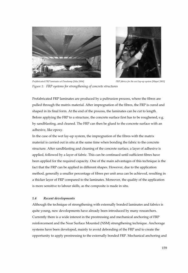
Prefabricated FRP laminates at Denekamp [Sika 2004] FRP fabrics for the wet lay-up system [Mapei 2001]
Figure 1: FRP systems for strengthening of concrete structures
Prefabricated FRP laminates are produced by a pultrusion process, where the fibres are
pulled through the matrix material. After impregnation of the fibres, the FRP is cured and
shaped in its final form. At the end of the process, the laminates can be cut to length.
Before applying the FRP to a structure, the concrete surface first has to be roughened, e.g.
by sandblasting, and cleaned. The FRP can then be glued to the concrete surface with an
adhesive, like epoxy.
In the case of the wet lay-up system, the impregnation of the fibres with the matrix
material is carried out in situ at the same time when bonding the fabric to the concrete
structure. After sandblasting and cleaning of the concrete surface, a layer of adhesive is
applied, followed by a layer of fabric. This can be continued until sufficient fibres have
been applied for the required capacity. One of the main advantages of this technique is the
fact that the FRP can be applied in different shapes. However, due to the application
method, generally a smaller percentage of fibres per unit area can be achieved, resulting in
a thicker layer of FRP compared to the laminates. Moreover, the quality of the application
is more sensitive to labour skills, as the composite is made in situ.
1.4 Recent developments
Although the technique of strengthening with externally bonded laminates and fabrics is
quite young, new developments have already been introduced by many researchers.
Currently there is a wide interest in the prestressing and mechanical anchoring of FRP
reinforcement and the Near Surface Mounted (NSM) strengthening technique. Anchorage
systems have been developed, mainly to avoid debonding of the FRP and to create the
opportunity to apply prestressing to the externally bonded FRP. Mechanical anchoring and
160
prestressing will result in a higher efficiency of the FRP, resulting in a higher capacity of
the strengthened structure [Garden et al., 1998; El-Hacha et al., 2001].
In the NSM strengthening technique [De Lorenzis et al., 2002], the FRP is bonded into a
slice in the concrete perpendicular to the surface. This has the benefit of a larger bonding
surface and thus the potential for a higher capacity of the strengthened beam. The FRP is
also better protected against environmental influences and vandalism. Another important
FRP strengthening technique is the wrapping of FRP around a column to increase the axial
capacity by confinement [fib, 2001].
1.5 Research objective
Last two decades, extensive research has been carried out into the strengthening of
structures with externally bonded FRP. Since guidelines, like fib Bulletin 14 in Europe [fib,
2001] and ACI 440.2R-02 in the USA [ACI, 2002], have become available, the number of
FRP-strengthening applications has increased enormously. An important aspect of FRP-
strengthened structures is the debonding of the FRP from the concrete surface before the
FRP tensile strength or concrete compressive strength is reached. Debonding of the FRP is
generally governed by the failure of concrete adjacent to the concrete-adhesive interface,
leaving a small layer of concrete remaining attached to the adhesive after debonding.
The debonding behaviour has been investigated quite extensively. Design guidelines
nowadays provide models for a safe design of a FRP-strengthened structure. Nevertheless,
there is still a need to increase the knowledge of and experience with FRP strengthening
applications, as well as to expand the field of application of these design guidelines. One of
the topics for which further research is required, is the influence of service temperature on
the debonding behaviour of externally bonded FRP. Accidental loss of the FRP due to
extreme temperatures (e.g. fire) is covered by most guidelines by verifying the
unstrengthened structure in the case of the accidental load situation. However, the effect
of temperature changes under service conditions, where temperatures up to 50°C or more
may occur, e.g. due to sun heating, is so far insufficiently investigated.
Temperature changes are expected to affect the material properties of the concrete, FRP
and the adhesive, but also the bond between these materials. Increasing the temperature is
expected to have a negative effect on the adhesive properties, especially when the glass-
transition temperature (Tg) is exceeded. Exceeding this temperature results in a significant
reduction of the strength and stiffness of the adhesive. Temperature changes will also
induce thermal stresses, due to the significant difference in the coefficient of thermal
161
expansion (CTE) between concrete (αc ≈ 10 × 10-6 /°C) and e.g. Carbon Fibre Reinforced
Polymers (CFRP) (αf ≈ -1 × 10⁻⁶ /°C in the longitudinal direction).
Research into the effect of temperature has, so far, only been carried out on small scale
bond tests. It was therefore decided to set up an experimental test program in which the
behaviour of full scale RC beams strengthened with externally bonded CFRP is
investigated at elevated temperatures.
In the next chapter, first an overview of the possible failure modes of FRP strengthened RC
beams is given, which is needed for a good understanding of the experimental results.
Chapter 3 deals with the results of small scale bond tests that have been carried out by
several researchers at low and high temperatures. The full scale test setup is discussed in
chapter 4 followed by the experimental test results in chapter 5 and the conclusions and
recommendations in chapter 6.
2 Failure of FRP strengthened structures
2.1 Flexural failure
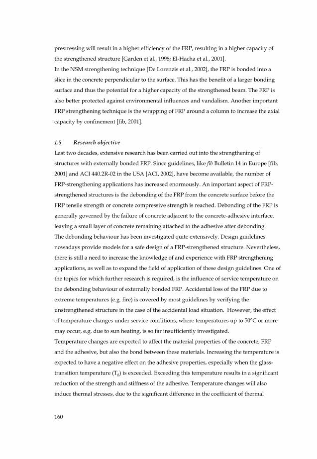
Flexural failure of a strengthened RC beams is quite similar to failure of non-strengthened
RC members, taken the additional FRP as additional reinforcement into account. When
debonding (Section 2.3) is prevented, flexural failure of a FRP strengthened beam is
governed by either FRP rupture (Figure 2) or crushing of the concrete in the compressive
zone (Figure 3). Both failure modes could occur before or after yielding of the internal steel
reinforcement. However, in practical applications, flexural failure is hardly ever observed,
as, in general, failure is governed by debonding of the externally bonded FRP.
FRP rupture
Figure 2: FRP rupture
Concrete crushing
Figure 3: Concrete crushing
2.2 Shear failure
FRP that is used to strengthen a structure in flexure does not significantly contribute to the
shear capacity of the beam and is therefore often neglected in the verification of the shear
capacity. Shear failure could become the governing failure mode (Figure 4), as the flexural
capacity is increased. Shear failure should however be avoided due to the brittleness of this
162
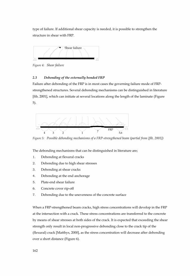
type of failure. If additional shear capacity is needed, it is possible to strengthen the
structure in shear with FRP.
Shear failure
Figure 4: Shear failure
2.3 Debonding of the externally bonded FRP
Failure after debonding of the FRP is in most cases the governing failure mode of FRP-
strengthened structures. Several debonding mechanisms can be distinguished in literature
[fib, 2001], which can initiate at several locations along the length of the laminate (Figure
5).
4 3 72 5,6FRP
1 Figure 5: Possible debonding mechanisms of a FRP-strengthened beam (partial from [fib, 2001])
The debonding mechanisms that can be distinguished in literature are;
1. Debonding at flexural cracks
2. Debonding due to high shear stresses
3. Debonding at shear cracks
4. Debonding at the end anchorage
5. Plate-end shear failure
6. Concrete cover rip-off
7. Debonding due to the unevenness of the concrete surface
When a FRP-strengthened beam cracks, high stress concentrations will develop in the FRP
at the intersection with a crack. These stress concentrations are transferred to the concrete
by means of shear stresses at both sides of the crack. It is expected that exceeding the shear
strength only result in local non-progressive debonding close to the crack tip of the
(flexural) crack [Matthys, 2000], as the stress concentration will decrease after debonding
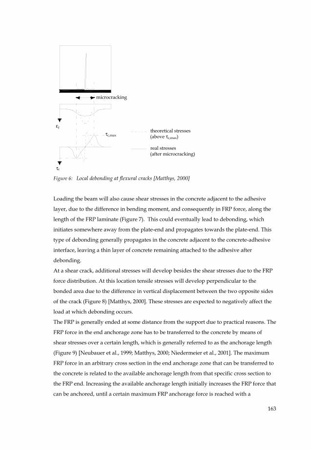
over a short distance (Figure 6).
163
εf
τc
τc,max
microcracking
theoretical stresses(above τc,max)
real stresses(after microcracking)
Figure 6: Local debonding at flexural cracks [Matthys, 2000]
Loading the beam will also cause shear stresses in the concrete adjacent to the adhesive
layer, due to the difference in bending moment, and consequently in FRP force, along the
length of the FRP laminate (Figure 7). This could eventually lead to debonding, which
initiates somewhere away from the plate-end and propagates towards the plate-end. This
type of debonding generally propagates in the concrete adjacent to the concrete-adhesive
interface, leaving a thin layer of concrete remaining attached to the adhesive after
debonding.
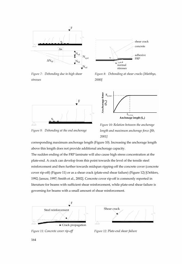
At a shear crack, additional stresses will develop besides the shear stresses due to the FRP
force distribution. At this location tensile stresses will develop perpendicular to the
bonded area due to the difference in vertical displacement between the two opposite sides
of the crack (Figure 8) [Matthys, 2000]. These stresses are expected to negatively affect the
load at which debonding occurs.
The FRP is generally ended at some distance from the support due to practical reasons. The
FRP force in the end anchorage zone has to be transferred to the concrete by means of
shear stresses over a certain length, which is generally referred to as the anchorage length
(Figure 9) [Neubauer et al., 1999; Matthys, 2000; Niedermeier et al., 2001]. The maximum
FRP force in an arbitrary cross section in the end anchorage zone that can be transferred to
the concrete is related to the available anchorage length from that specific cross section to
the FRP end. Increasing the available anchorage length initially increases the FRP force that
can be anchored, until a certain maximum FRP anchorage force is reached with a
164
F
Δx
τc
Nfd
Nsd
ΔNfd
Nsyd
Nsd Figure 7: Debonding due to high shear
stresses
shear crack
concrete
adhesiveFRPv
wnormalstresses
Figure 8: Debonding at shear cracks [Matthys,
2000]
F
τc
Figure 9: Debonding at the end anchorage
Figure 10: Relation between the anchorage
length and maximum anchorage force [fib,
2001]
corresponding maximum anchorage length (Figure 10). Increasing the anchorage length
above this length does not provide additional anchorage capacity.
The sudden ending of the FRP laminate will also cause high stress concentration at the
plate-end. A crack can develop from this point towards the level of the tensile steel
reinforcement and then further towards midspan ripping-off the concrete cover (concrete
cover rip-off) (Figure 11) or as a shear crack (plate-end shear failure) (Figure 12) [Oehlers,
1992; Jansze, 1997; Smith et al., 2002]. Concrete cover rip-off is commonly reported in
literature for beams with sufficient shear reinforcement, while plate-end shear failure is
governing for beams with a small amount of shear reinforcement.
Crack propagation
F
Steel reinforcement
Figure 11: Concrete cover rip-off
Shear crack
Figure 12: Plate-end shear failure
165
3 Previous research into the effect of temperature on the debonding
3.1 Introduction
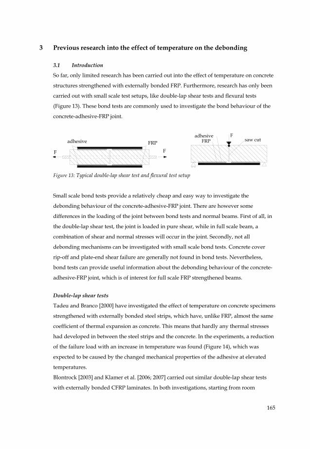
So far, only limited research has been carried out into the effect of temperature on concrete
structures strengthened with externally bonded FRP. Furthermore, research has only been
carried out with small scale test setups, like double-lap shear tests and flexural tests
(Figure 13). These bond tests are commonly used to investigate the bond behaviour of the
concrete-adhesive-FRP joint.
FRPadhesive
FF
FRPadhesive F
saw cut
Figure 13: Typical double-lap shear test and flexural test setup
Small scale bond tests provide a relatively cheap and easy way to investigate the
debonding behaviour of the concrete-adhesive-FRP joint. There are however some
differences in the loading of the joint between bond tests and normal beams. First of all, in
the double-lap shear test, the joint is loaded in pure shear, while in full scale beam, a
combination of shear and normal stresses will occur in the joint. Secondly, not all
debonding mechanisms can be investigated with small scale bond tests. Concrete cover
rip-off and plate-end shear failure are generally not found in bond tests. Nevertheless,
bond tests can provide useful information about the debonding behaviour of the concrete-
adhesive-FRP joint, which is of interest for full scale FRP strengthened beams.
Double-lap shear tests
Tadeu and Branco [2000] have investigated the effect of temperature on concrete specimens
strengthened with externally bonded steel strips, which have, unlike FRP, almost the same
coefficient of thermal expansion as concrete. This means that hardly any thermal stresses
had developed in between the steel strips and the concrete. In the experiments, a reduction
of the failure load with an increase in temperature was found (Figure 14), which was
expected to be caused by the changed mechanical properties of the adhesive at elevated
temperatures.
Blontrock [2003] and Klamer et al. [2006; 2007] carried out similar double-lap shear tests
with externally bonded CFRP laminates. In both investigations, starting from room
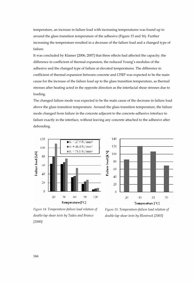
166
temperature, an increase in failure load with increasing temperatures was found up to
around the glass transition temperature of the adhesive (Figure 15 and 16). Further
increasing the temperature resulted in a decrease of the failure load and a changed type of
failure.
It was concluded by Klamer [2006; 2007] that three effects had affected the capacity; the
difference in coefficient of thermal expansion, the reduced Young’s modulus of the
adhesive and the changed type of failure at elevated temperatures. The difference in
coefficient of thermal expansion between concrete and CFRP was expected to be the main
cause for the increase of the failure load up to the glass transition temperature, as thermal
stresses after heating acted in the opposite direction as the interfacial shear stresses due to
loading.
The changed failure mode was expected to be the main cause of the decrease in failure load
above the glass transition temperature. Around the glass transition temperature, the failure
mode changed from failure in the concrete adjacent to the concrete-adhesive interface to
failure exactly in the interface, without leaving any concrete attached to the adhesive after
debonding.
Figure 14: Temperature-failure load relation of
double-lap shear tests by Tadeu and Branco
[2000]
Figure 15: Temperature-failure load relation of
double-lap shear tests by Blontrock [2003]
167
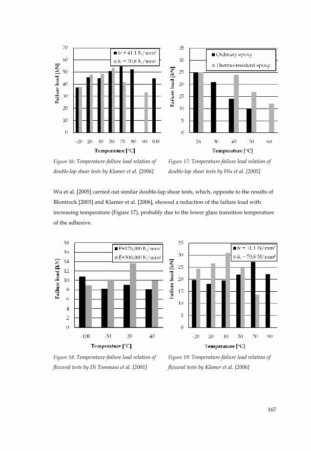
Figure 16: Temperature-failure load relation of
double-lap shear tests by Klamer et al. [2006]
Figure 17: Temperature-failure load relation of
double-lap shear tests by Wu et al. [2005]
Wu et al. [2005] carried out similar double-lap shear tests, which, opposite to the results of
Blontrock [2003] and Klamer et al. [2006], showed a reduction of the failure load with
increasing temperature (Figure 17), probably due to the lower glass transition temperature
of the adhesive.
Figure 18: Temperature-failure load relation of
flexural tests by Di Tommaso et al. [2001]
Figure 19: Temperature-failure load relation of
flexural tests by Klamer et al. [2006]
168
3.2 Flexural tests
Di Tommaso et al. [2001] investigated the influence of temperature in three point bending
tests at temperatures ranging from -100°C up to 40°C. Relative to the failure load at room
temperature, decreasing failure loads were found both for increasing and decreasing
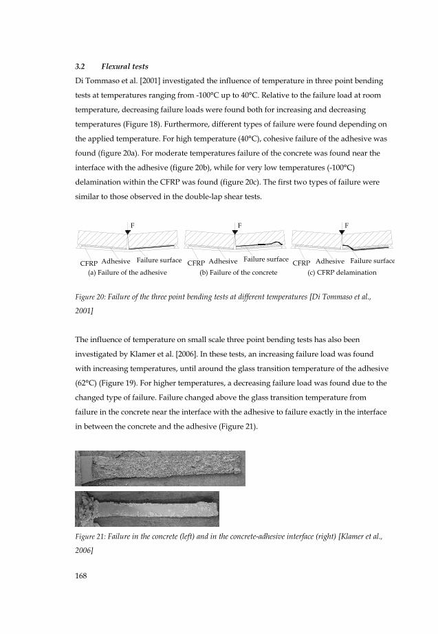
temperatures (Figure 18). Furthermore, different types of failure were found depending on
the applied temperature. For high temperature (40°C), cohesive failure of the adhesive was
found (figure 20a). For moderate temperatures failure of the concrete was found near the
interface with the adhesive (figure 20b), while for very low temperatures (-100°C)
delamination within the CFRP was found (figure 20c). The first two types of failure were
similar to those observed in the double-lap shear tests.
F
Failure surfaceAdhesiveCFRP
F
Failure surfaceAdhesiveCFRP
F
Failure surfaceAdhesiveCFRP(c) CFRP delamination(b) Failure of the concrete(a) Failure of the adhesive
Figure 20: Failure of the three point bending tests at different temperatures [Di Tommaso et al.,
2001]
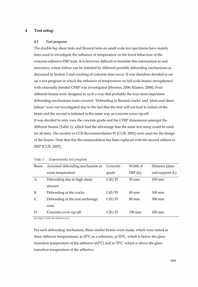
The influence of temperature on small scale three point bending tests has also been
investigated by Klamer et al. [2006]. In these tests, an increasing failure load was found
with increasing temperatures, until around the glass transition temperature of the adhesive
(62°C) (Figure 19). For higher temperatures, a decreasing failure load was found due to the
changed type of failure. Failure changed above the glass transition temperature from
failure in the concrete near the interface with the adhesive to failure exactly in the interface
in between the concrete and the adhesive (Figure 21).
Figure 21: Failure in the concrete (left) and in the concrete-adhesive interface (right) [Klamer et al.,
2006]
169
4 Test setup
4.1 Test program
The double-lap shear tests and flexural tests on small scale test specimens have mainly
been used to investigate the influence of temperature on the bond behaviour of the
concrete-adhesive-FRP joint. It is however difficult to translate this information to real
structures, where failure can be initiated by different possible debonding mechanisms as
discussed in Section 2 and cracking of concrete does occur. It was therefore decided to set
up a test program in which the influence of temperature on full scale beams strengthened
with externally bonded CFRP was investigated [Hermes, 2006; Klamer, 2008]. Four
different beams were designed in such a way that probably the four most important
debonding mechanisms were covered. ‘Debonding at flexural cracks’ and ‘plate-end shear
failure’ were not investigated due to the fact that the first will not lead to failure of the
beam and the second is initiated in the same way as concrete cover rip-off.
It was decided to only vary the concrete grade and the CFRP dimensions amongst the
different beams (Table 1), which had the advantage that the same test setup could be used
for all tests. The models in CUR Recommendation 91 [CUR, 2002] were used for the design
of the beams. Note that this Recommendation has been replaced with the second edition in
2007 [CUR, 2007].
Table 1: Experimental test program
Beam Assumed debonding mechanism at
room temperature
Concrete
grade
Width of
FRP (bf)
Distance plate-
end-support (L)
A Debonding due to high shear
stresses
C20/25 50 mm 100 mm
B Debonding at the cracks C45/55 80 mm 100 mm
C Debonding at the end anchorage
zone
C45/55 80 mm 300 mm
D Concrete cover rip-off C20/25 150 mm 100 mm See Figure 22 for the definition of L.
For each debonding mechanism, three similar beams were made, which were tested at
three different temperatures; at 20°C as a reference, at 50°C, which is below the glass
transition temperature of the adhesive (62°C) and at 70°C, which is above the glass
transition temperature of the adhesive.
170
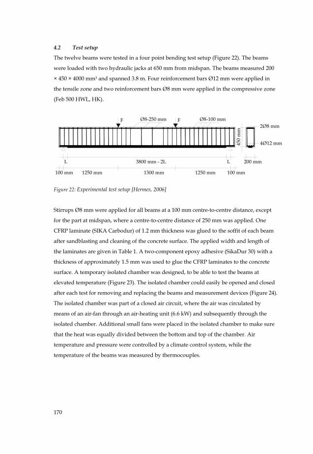
4.2 Test setup
The twelve beams were tested in a four point bending test setup (Figure 22). The beams
were loaded with two hydraulic jacks at 650 mm from midspan. The beams measured 200
× 450 × 4000 mm3 and spanned 3.8 m. Four reinforcement bars Ø12 mm were applied in
the tensile zone and two reinforcement bars Ø8 mm were applied in the compressive zone
(Feb 500 HWL, HK).
F F
L
100 mm
3800 mm - 2L
1300 mm1250 mm 1250 mm
L
100 mm
450
mm
200 mm
4Ø12 mm
2Ø8 mmØ8-100 mmØ8-250 mm
Figure 22: Experimental test setup [Hermes, 2006]
Stirrups Ø8 mm were applied for all beams at a 100 mm centre-to-centre distance, except
for the part at midspan, where a centre-to-centre distance of 250 mm was applied. One
CFRP laminate (SIKA Carbodur) of 1.2 mm thickness was glued to the soffit of each beam
after sandblasting and cleaning of the concrete surface. The applied width and length of
the laminates are given in Table 1. A two-component epoxy adhesive (SikaDur 30) with a
thickness of approximately 1.5 mm was used to glue the CFRP laminates to the concrete
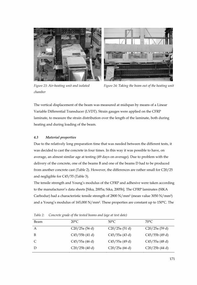
surface. A temporary isolated chamber was designed, to be able to test the beams at
elevated temperature (Figure 23). The isolated chamber could easily be opened and closed
after each test for removing and replacing the beams and measurement devices (Figure 24).
The isolated chamber was part of a closed air circuit, where the air was circulated by
means of an air-fan through an air-heating unit (6.6 kW) and subsequently through the
isolated chamber. Additional small fans were placed in the isolated chamber to make sure
that the heat was equally divided between the bottom and top of the chamber. Air
temperature and pressure were controlled by a climate control system, while the
temperature of the beams was measured by thermocouples.
171
The vertical displacement of the beam was measured at midspan by means of a Linear
Variable Differential Transducer (LVDT). Strain gauges were applied on the CFRP
laminate, to measure the strain distribution over the length of the laminate, both during
heating and during loading of the beam.
4.3 Material properties
Due to the relatively long preparation time that was needed between the different tests, it
was decided to cast the concrete in four times. In this way it was possible to have, on
average, an almost similar age at testing (49 days on average). Due to problem with the
delivery of the concrete, one of the beams B and one of the beams D had to be produced
from another concrete cast (Table 2). However, the differences are rather small for C20/25
and negligible for C45/55 (Table 3).
The tensile strength and Young’s modulus of the CFRP and adhesive were taken according
to the manufacturer’s data sheets [Sika, 2005a; Sika, 2005b]. The CFRP laminates (SIKA
Carbodur) had a characteristic tensile strength of 2800 N/mm² (mean value 3050 N/mm²)
and a Young’s modulus of 165,000 N/mm². These properties are constant up to 150°C. The
Table 2: Concrete grade of the tested beams and (age at test date)
Beam 20°C 50°C 70°C
A C20/25a (56 d) C20/25a (51 d) C20/25a (59 d)
B C45/55b (41 d) C45/55a (43 d) C45/55b (49 d)
C C45/55a (46 d) C45/55a (49 d) C45/55a (48 d)
D C20/25b (40 d) C20/25a (66 d) C20/25b (44 d)
Figure 23: Air-heating unit and isolated
chamber
Figure 24: Taking the beam out of the heating unit
172
Table 3: Mean values of the concrete material properties at room temperature (28 days)
Material properties C20/25a C20/25b C45/55a C45/55b
Compressive strength
(fcm,cube)
27.7 N/mm² 36.0 N/mm² 51.2 N/mm² 52.3 N/mm²
Tensile splitting strength
(fctm,sp)
2.3 N/mm² 3.0 N/mm² 3.7 N/mm² 3.6 N/mm²
Young’s modulus (Ecm) 21,600 N/mm² 19,400 N/mm² 24,600 N/mm² 25,200 N/mm²
coefficient of thermal expansion was determined experimentally in this investigation with
Electronic Speckle Pattern Interferometry (ESPI) and was equal to -0.3×10⁻⁶/°C in the fibre
direction and 33×10-6/°C in the direction perpendicular to the fibre direction.
The adhesive was a two-component epoxy adhesive (SikaDur-30) with a Young’s modulus
of 12,800 N/mm², a tensile strength between 24 N/mm² and 31 N/mm² and a glass
transition temperature of 62°C. The coefficient of thermal expansion was experimentally
determined in this investigation according to EN 1770 [CEN, 1998] and was equal to 26×10-
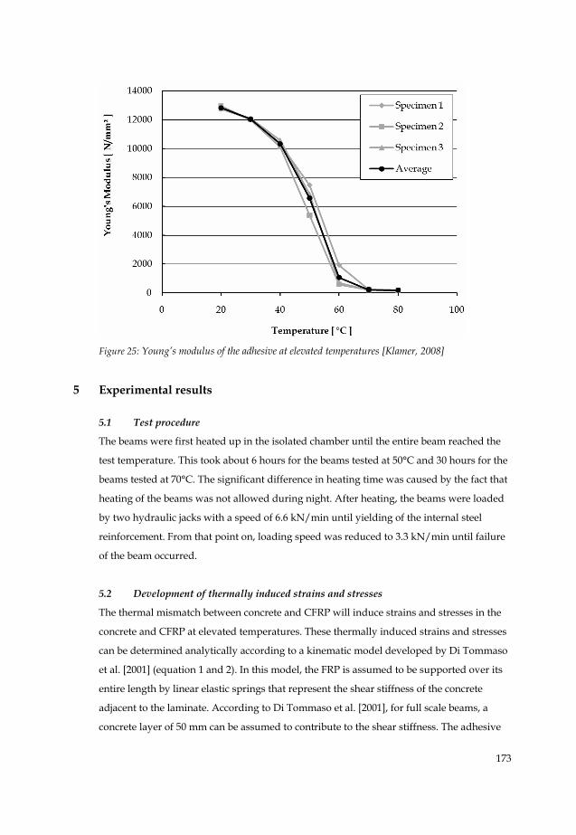
6/°C. Since the Young’s modulus of the adhesive was expected to be strongly dependent
on the temperature, it was decided to determine it at different temperatures ranging from
20°C till 80°C (Figure 26). The specimens were heated at 80°C for two days, prior to
testing. It can be seen that even below the glass transition temperature of the adhesive
(62°C) a significant reduction of the Young’s modulus was found.
The bond strength of the concrete-adhesive joint perpendicular to the bonded surface was
experimentally determined according to CUR Recommendation 20 [CUR, 1990], by
pulling-off a bonded steel cylinder Ø50 mm from the concrete surface. The tests were
carried out at 20°C, 50°C and 70°C (Table 4).
Table 4: Mean values of the concrete bond strength (28 days)
Mean concrete bond strength (fcbm) C20/25a C20/25b C40/45a C40/45b
20°C 2.60 N/mm² 2.78
N/mm²
4.48
N/mm²
4.79
N/mm²
50°C 1.83 N/mm² 2.17
N/mm²
3.87
N/mm²
3.77
N/mm²
70°C n/a 1.27
N/mm²
2.44
N/mm²
2.85
N/mm²
173
Figure 25: Young’s modulus of the adhesive at elevated temperatures [Klamer, 2008]
5 Experimental results
5.1 Test procedure
The beams were first heated up in the isolated chamber until the entire beam reached the
test temperature. This took about 6 hours for the beams tested at 50°C and 30 hours for the
beams tested at 70°C. The significant difference in heating time was caused by the fact that
heating of the beams was not allowed during night. After heating, the beams were loaded
by two hydraulic jacks with a speed of 6.6 kN/min until yielding of the internal steel
reinforcement. From that point on, loading speed was reduced to 3.3 kN/min until failure
of the beam occurred.
5.2 Development of thermally induced strains and stresses
The thermal mismatch between concrete and CFRP will induce strains and stresses in the
concrete and CFRP at elevated temperatures. These thermally induced strains and stresses
can be determined analytically according to a kinematic model developed by Di Tommaso
et al. [2001] (equation 1 and 2). In this model, the FRP is assumed to be supported over its
entire length by linear elastic springs that represent the shear stiffness of the concrete
adjacent to the laminate. According to Di Tommaso et al. [2001], for full scale beams, a
concrete layer of 50 mm can be assumed to contribute to the shear stiffness. The adhesive
174
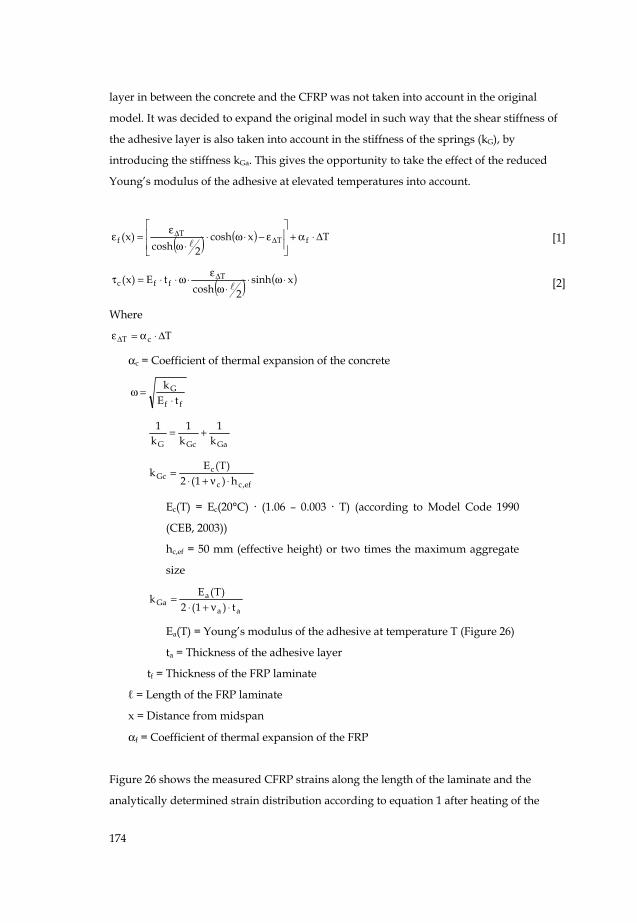
layer in between the concrete and the CFRP was not taken into account in the original
model. It was decided to expand the original model in such way that the shear stiffness of
the adhesive layer is also taken into account in the stiffness of the springs (kG), by
introducing the stiffness kGa. This gives the opportunity to take the effect of the reduced
Young’s modulus of the adhesive at elevated temperatures into account.
( ) ( ) Txcosh2cosh
)x( fTT
f Δ⋅α+⎥⎥⎦
⎤
⎢⎢⎣
⎡ε−⋅ω⋅
⋅ωε
=ε ΔΔ [1]
( ) ( )xsinh2cosh
tE)x( Tffc ⋅ω⋅
⋅ωε
⋅ω⋅⋅=τ Δ [2]
Where
TcT Δ⋅α=εΔ
αc = Coefficient of thermal expansion of the concrete
ff
GtE
k⋅
=ω
GaGcG k1
k1
k1 +=
ef,cc
cGc h)1(2
)T(Ek⋅ν+⋅
=
Ec(T) = Ec(20°C) · (1.06 – 0.003 · T) (according to Model Code 1990
(CEB, 2003))
hc,ef = 50 mm (effective height) or two times the maximum aggregate
size
aa
aGa t)1(2
)T(Ek⋅ν+⋅
=
Ea(T) = Young’s modulus of the adhesive at temperature T (Figure 26)
ta = Thickness of the adhesive layer
tf = Thickness of the FRP laminate
ℓ = Length of the FRP laminate
x = Distance from midspan
αf = Coefficient of thermal expansion of the FRP
Figure 26 shows the measured CFRP strains along the length of the laminate and the
analytically determined strain distribution according to equation 1 after heating of the
175
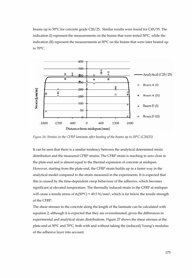
beams up to 50°C for concrete grade C20/25. Similar results were found for C45/55. The
indication (I) represent the measurements on the beams that were tested 50°C, while the
indication (II) represent the measurements at 50°C on the beams that were later heated up
to 70°C.
Figure 26: Strains in the CFRP laminate after heating of the beams up to 50°C (C20/25)
It can be seen that there is a similar tendency between the analytical determined strain
distribution and the measured CFRP strains. The CFRP strain is reaching to zero close to
the plate-end and is almost equal to the thermal expansion of concrete at midspan.
However, starting from the plate-end, the CFRP strain builds up in a faster way in the
analytical model compared to the strain measured in the experiments. It is expected that
this is caused by the time-dependent creep behaviour of the adhesive, which becomes
significant at elevated temperature. The thermally induced strain in the CFRP at midspan
will cause a tensile stress of σf(50°C) = 49.5 N/mm², which is far below the tensile strength
of the CFRP.
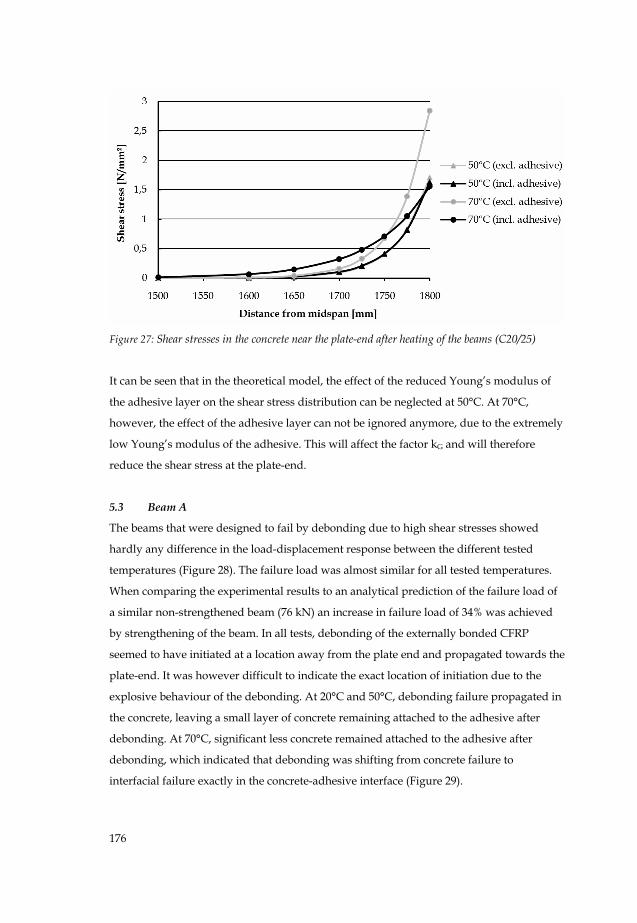
The shear stresses in the concrete along the length of the laminate can be calculated with
equation 2, although it is expected that they are overestimated, given the differences in
experimental and analytical strain distributions. Figure 27 shows the shear stresses at the
plate-end at 50°C and 70°C, both with and without taking the (reduced) Young’s modulus
of the adhesive layer into account.
176
Figure 27: Shear stresses in the concrete near the plate-end after heating of the beams (C20/25)
It can be seen that in the theoretical model, the effect of the reduced Young’s modulus of
the adhesive layer on the shear stress distribution can be neglected at 50°C. At 70°C,
however, the effect of the adhesive layer can not be ignored anymore, due to the extremely
low Young’s modulus of the adhesive. This will affect the factor kG and will therefore
reduce the shear stress at the plate-end.
5.3 Beam A
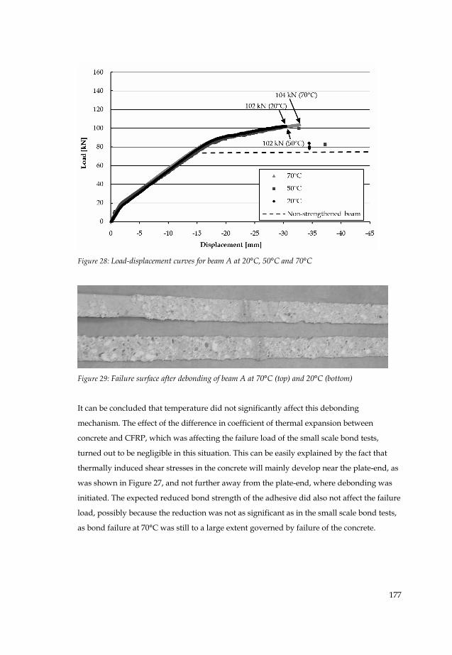
The beams that were designed to fail by debonding due to high shear stresses showed
hardly any difference in the load-displacement response between the different tested
temperatures (Figure 28). The failure load was almost similar for all tested temperatures.
When comparing the experimental results to an analytical prediction of the failure load of
a similar non-strengthened beam (76 kN) an increase in failure load of 34% was achieved
by strengthening of the beam. In all tests, debonding of the externally bonded CFRP
seemed to have initiated at a location away from the plate end and propagated towards the
plate-end. It was however difficult to indicate the exact location of initiation due to the
explosive behaviour of the debonding. At 20°C and 50°C, debonding failure propagated in
the concrete, leaving a small layer of concrete remaining attached to the adhesive after
debonding. At 70°C, significant less concrete remained attached to the adhesive after
debonding, which indicated that debonding was shifting from concrete failure to
interfacial failure exactly in the concrete-adhesive interface (Figure 29).
177
Figure 28: Load-displacement curves for beam A at 20°C, 50°C and 70°C
Figure 29: Failure surface after debonding of beam A at 70°C (top) and 20°C (bottom)
It can be concluded that temperature did not significantly affect this debonding
mechanism. The effect of the difference in coefficient of thermal expansion between
concrete and CFRP, which was affecting the failure load of the small scale bond tests,
turned out to be negligible in this situation. This can be easily explained by the fact that
thermally induced shear stresses in the concrete will mainly develop near the plate-end, as
was shown in Figure 27, and not further away from the plate-end, where debonding was
initiated. The expected reduced bond strength of the adhesive did also not affect the failure
load, possibly because the reduction was not as significant as in the small scale bond tests,
as bond failure at 70°C was still to a large extent governed by failure of the concrete.
178
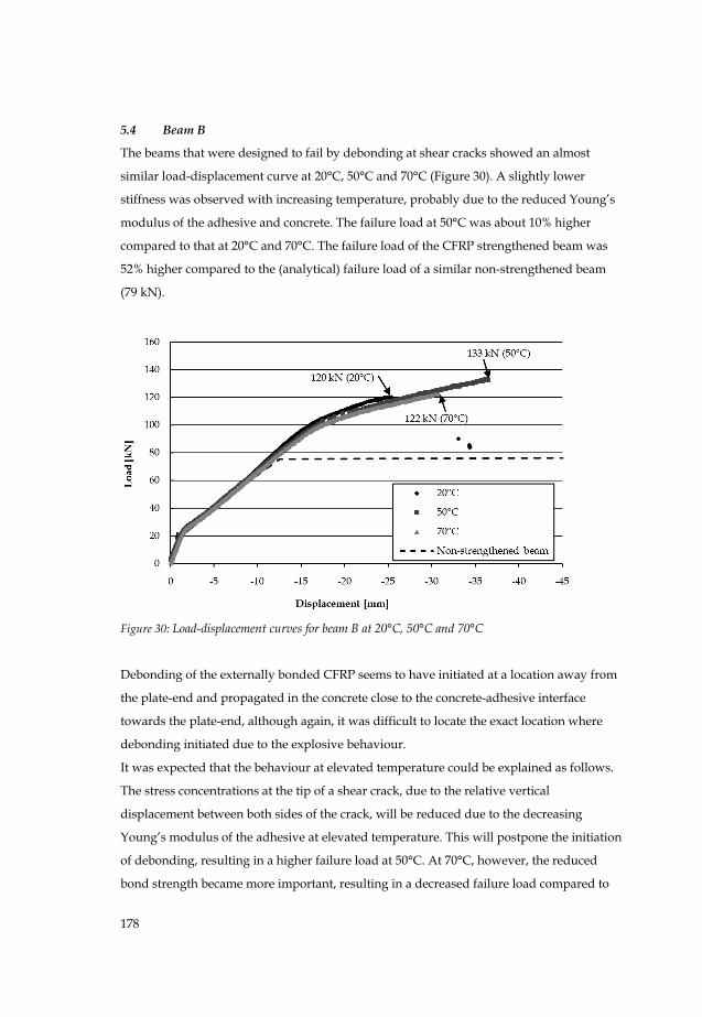
5.4 Beam B
The beams that were designed to fail by debonding at shear cracks showed an almost
similar load-displacement curve at 20°C, 50°C and 70°C (Figure 30). A slightly lower
stiffness was observed with increasing temperature, probably due to the reduced Young’s
modulus of the adhesive and concrete. The failure load at 50°C was about 10% higher
compared to that at 20°C and 70°C. The failure load of the CFRP strengthened beam was
52% higher compared to the (analytical) failure load of a similar non-strengthened beam
(79 kN).
Figure 30: Load-displacement curves for beam B at 20°C, 50°C and 70°C
Debonding of the externally bonded CFRP seems to have initiated at a location away from
the plate-end and propagated in the concrete close to the concrete-adhesive interface
towards the plate-end, although again, it was difficult to locate the exact location where
debonding initiated due to the explosive behaviour.
It was expected that the behaviour at elevated temperature could be explained as follows.
The stress concentrations at the tip of a shear crack, due to the relative vertical
displacement between both sides of the crack, will be reduced due to the decreasing
Young’s modulus of the adhesive at elevated temperature. This will postpone the initiation
of debonding, resulting in a higher failure load at 50°C. At 70°C, however, the reduced
bond strength became more important, resulting in a decreased failure load compared to
179
the failure load at 50°C. The effect of the difference in coefficient of thermal expansion
between concrete and CFRP was expected to be negligible, as these stresses develop at the
plate-end, while debonding was initiated at some distance from the plate-end, similar as
for beam A.
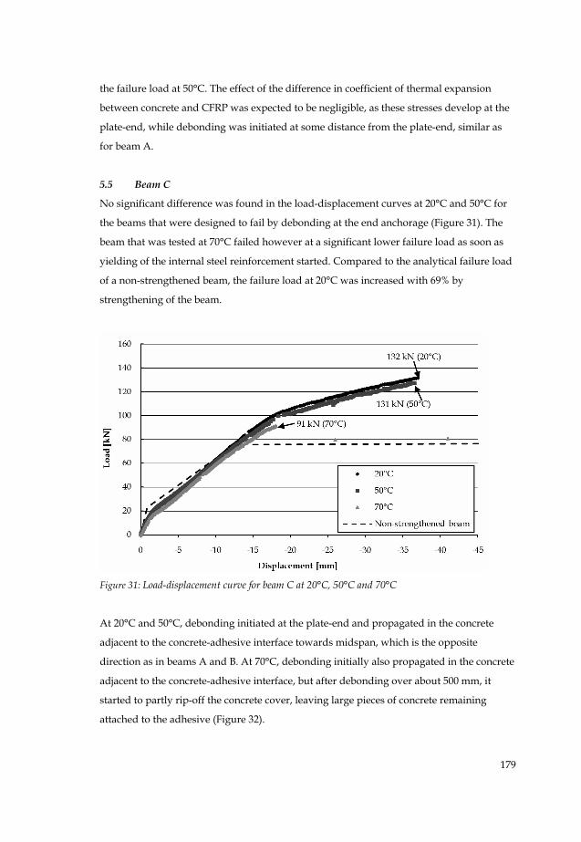
5.5 Beam C
No significant difference was found in the load-displacement curves at 20°C and 50°C for
the beams that were designed to fail by debonding at the end anchorage (Figure 31). The
beam that was tested at 70°C failed however at a significant lower failure load as soon as
yielding of the internal steel reinforcement started. Compared to the analytical failure load
of a non-strengthened beam, the failure load at 20°C was increased with 69% by
strengthening of the beam.
Figure 31: Load-displacement curve for beam C at 20°C, 50°C and 70°C
At 20°C and 50°C, debonding initiated at the plate-end and propagated in the concrete
adjacent to the concrete-adhesive interface towards midspan, which is the opposite
direction as in beams A and B. At 70°C, debonding initially also propagated in the concrete
adjacent to the concrete-adhesive interface, but after debonding over about 500 mm, it
started to partly rip-off the concrete cover, leaving large pieces of concrete remaining
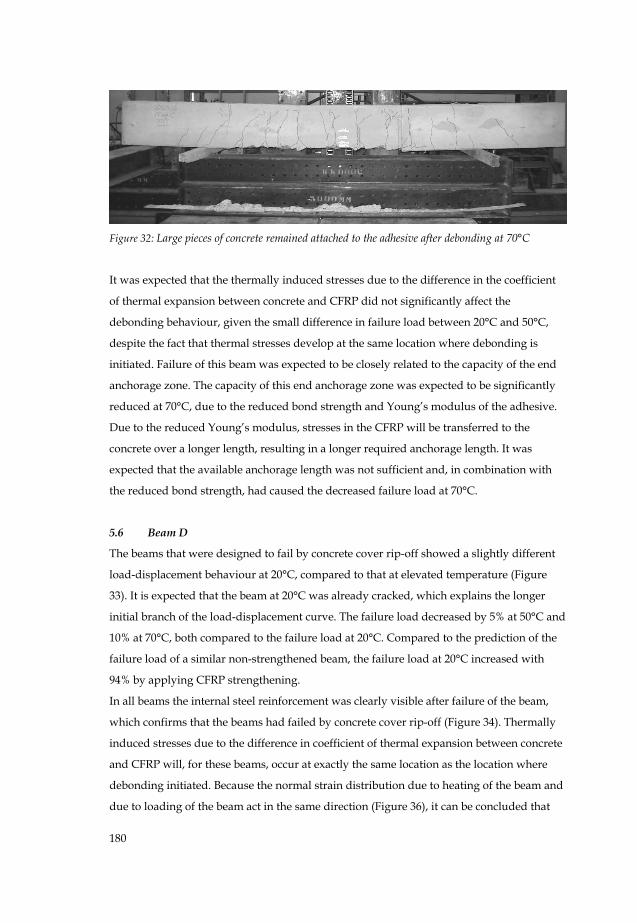
attached to the adhesive (Figure 32).
180
Figure 32: Large pieces of concrete remained attached to the adhesive after debonding at 70°C
It was expected that the thermally induced stresses due to the difference in the coefficient
of thermal expansion between concrete and CFRP did not significantly affect the
debonding behaviour, given the small difference in failure load between 20°C and 50°C,
despite the fact that thermal stresses develop at the same location where debonding is
initiated. Failure of this beam was expected to be closely related to the capacity of the end
anchorage zone. The capacity of this end anchorage zone was expected to be significantly
reduced at 70°C, due to the reduced bond strength and Young’s modulus of the adhesive.
Due to the reduced Young’s modulus, stresses in the CFRP will be transferred to the
concrete over a longer length, resulting in a longer required anchorage length. It was
expected that the available anchorage length was not sufficient and, in combination with
the reduced bond strength, had caused the decreased failure load at 70°C.
5.6 Beam D
The beams that were designed to fail by concrete cover rip-off showed a slightly different
load-displacement behaviour at 20°C, compared to that at elevated temperature (Figure
33). It is expected that the beam at 20°C was already cracked, which explains the longer
initial branch of the load-displacement curve. The failure load decreased by 5% at 50°C and
10% at 70°C, both compared to the failure load at 20°C. Compared to the prediction of the
failure load of a similar non-strengthened beam, the failure load at 20°C increased with
94% by applying CFRP strengthening.
In all beams the internal steel reinforcement was clearly visible after failure of the beam,
which confirms that the beams had failed by concrete cover rip-off (Figure 34). Thermally
induced stresses due to the difference in coefficient of thermal expansion between concrete
and CFRP will, for these beams, occur at exactly the same location as the location where
debonding initiated. Because the normal strain distribution due to heating of the beam and
due to loading of the beam act in the same direction (Figure 36), it can be concluded that

181
Figure 33: Load-displacement curve for beam D at 20°C, 50°C and 70°C
the thermally induced shear stresses will also act in the same direction and are therefore
expected to have negatively affected the failure load. The reduced Young’s modulus of the
adhesive will however partly reduce the stress concentrations at the plate end, as has been
shown in Figure 27. The combined effect on the failure load turned out to be small, as can
be seen in Figure 33. The effect of the reduced bond strength does in this case not play a
significant role, as failure is governed by failure of the concrete and not by the bond failure
near the interface with the adhesive.
Figure 34: Internal steel reinforcement is clearly visible after concrete cover rip-off

182
Figure 35: Normal strain in the CFRP laminate due to temperature and due to loading of the beam
(70°C)
6 Conclusions
6.1 Conclusions
In the investigation, four different CFRP-strengthened RC beams that were designed to fail
by four different debonding mechanisms have been investigated at 20°C, 50°C and 70°C.
For all the beams tested at 50°C, no change in the type of debonding was observed
compared to the beams tested at 20°C. The failure load was also not (significantly) affected
at 50°C, compared to room temperature, despite the reduction of the Young’s modulus of
the adhesive and bond strength of the concrete surface. The significant difference in
coefficient of thermal expansion between concrete and CFRP was expected to only have
had a small negative effect on the failure load of the beam that failed by concrete cover rip-
off, as thermal stresses developed at the same location where failure initiated.
At 70°C, the type of failure changed for only one of the beams. For beam A, debonding
failure changed from bond failure in the concrete to failure where significant less concrete
remained attached to the adhesive. The failure loads of the beams in which debonding
initiated at a location away from the plate-end (beam A and B) were not significantly
affected by temperature, as thermal stresses mainly developed at the plate-end and not at a
location where debonding was initiated.
The failure load of beam C that failed by debonding at the end anchorage was significantly
lower at 70°C compared to room temperature. For this beam, which had a shorter laminate
length, debonding was expected to be mainly related to the capacity of the anchorage zone,
183
which is expected to be negatively affected by both the reduced Young’s modulus of the
adhesive and the reduced bond strength of the concrete-adhesive joint at 70°C. Beam D,
which failed by concrete cover rip-off, was only slightly affected by temperature at 70°C,
due to the same reason as at 50°C. The effect on the failure load was however only small,
probably due to the positive effect of the reduced Young’s modulus and time dependent
creep behaviour of the adhesive, which reduces the stress concentrations at the plate-end.
6.2 Recommendations
Based on the test results, there is no need to take the effect of temperature into account in
the design of a FRP-strengthened structure as long as the temperature stays below 50°C (≈
Tg – 10°C). Strengthening of structures at temperatures above this temperature should be
avoided, due to the possible change in type of bond failure and corresponding reduced
bond strength. At these temperatures, extra precautions can possibly be taken to avoid
premature debonding. One of the possibilities is the application of anchorage which
prevents debonding, although further investigation into the effect of temperature on the
anchorage should be carried out before applying in practice. It is also possible to choose a
different type of adhesive with a higher Tg or to increase Tg by post-curing of the adhesive.
Acknowledgement
The authors wish to thank to the Civil Engineering division of the Dutch Ministry of
Transport, Public Works and Water Management that supported this investigation and
SIKA Nederland BV for supplying the CFRP laminates and the adhesive free of charge.
Furthermore, the authors are indebted to the personnel of the Pieter van Musschenbroek
laboratory of Eindhoven University of Technology, who assisted with the experiments.
References
ACI (2002) ACI 440.2R-02 Guide for the Design and Construction of Externally Bonded FRP
Systems for Strengthening Concrete Structures, Farmington Hills, Michigan: American
Concrete Institute.
Blontrock, H. (2003) Analyse en modellering van de brandweerstand van betonelementen
uitwendig versterkt met opgelijmde composietlaminaten (in Dutch), Ghent: PhD Thesis
Ghent University.
CEB (1993) CEB-FIP model code 1990: design code. Lausanne, Switzerland: Comité Euro-
International du Béton.
184
CEN (1998) EN 1770: Products and systems for the protection and repair of concrete structures -
Test methods - Determination of the coefficient of thermal expansion, Brussels: CEN.
CUR (1990) CUR Aanbeveling 20. Bepaling van de hechtsterkte van mortels op beton (in Dutch),
Gouda: Stichting CUR.
CUR (2002) CUR Aanbeveling 91. Versterken van gewapend-betonconstructies met uitwendig
gelijmde koolstofvezelwapening (in Dutch), first edition, Gouda: Stichting CUR.
CUR (2007) CUR Aanbeveling 91. Versterken van gewapend-betonconstructies met uitwendig
gelijmde koolstofvezelwapening (in Dutch), second edition, Gouda: Stichting CUR.
De Lorenzis, L., A. Rizzo and A. La Tegola (2002) 'A modified pull-out test for bond of
near-surface mounted FRP rods in concrete' in Composites Part B: Engineering Vol. 33,
Nr. 8, pp. 589-603.
Di Tommaso, A., U. Neubauer, A. Pantuso and F. S. Rostásy (2001) 'Behavior of adhesively
bonded concrete-CFRP joints at low and high temperatures' in Mechanics of Composite
Materials Vol. 37, Nr. 4, pp. 327-338.
El-Hacha, R., R. G. Wight and M. F. Green (2001) 'Prestressed fibre-reinforced polymer
laminates for strengthening structures' in Progress in Structural Engineering and Materials
Vol. 3, pp. 111-121.
fib (2001) fib Bulletin 14. Externally bonded FRP reinforcement for RC structures, Lausanne:
fédération internationale du béton.
Garden, H. N. and L. C. Hollaway (1998) 'An experimental study of the influence of plate
end anchorage of carbon fibre composite plates used to strengthen reinforced concrete
beams' in Composite Structures Vol. 42, Nr. 2, pp. 175-188.
Hermes, M.C.J. (2006) The influence of temperature on reinforced concrete structures
strengthened with externally bonded Carbon Fiber Reinforced Polymers, Eindhoven: Master
Thesis Eindhoven University of Technology.
Jansze, W. (1997) Strengthening of reinforced concrete members in bending by externally bonded
steel plates: design for beam shear and plate anchorage, Delft: PhD Thesis Delft University of
Technology.
Klamer, E. L. (2008) Influence of temperature on CFRP strengthening of concrete structures,
Eindhoven: PhD Thesis Eindhoven University of Technology.
Klamer, E. L., D. A. Hordijk and A. de Boer (2007) 'FE-analyses to study the effect of
temperature on debonding of externally bonded CFRP' Proceedings of 8th International
Symposium on Fiber Reinforced Polymer Reinforcement for Concrete Structures (FRPRCS-8),
CD-rom.
185
Klamer, E. L., D. A. Hordijk and C. S. Kleinman (2006) 'Debonding of CFRP laminates
externally bonded to concrete specimens at low and high temperatures' in Mirmiran, A.
and Nanni, A. (Eds.) Third International Conference on FRP Composites in Civil Engineering
(CICE 2006), pp. 35-38.
Mapei (2001) Mapei FRP System
Matthys, S. (2000) Structural behaviour and design of concrete members strengthened with
externally bonded FRP reinforcement, Ghent: PhD Thesis Ghent University.
Neubauer, U. and F. S. Rostásy (1999) 'Bond Failure of Concrete Fiber Reinforced Polymer
Plates at Inclined Cracks – Experiments and Fracture Mechanics Model' in Dolan, B. E.,
Rizkalla, S. H., and Nanni, A. (Eds.) Proceedings of the Fourth International Symposium,
Non-Metallic (FRP) Reinforcement for Concrete Structures, pp. 369-382.
Niedermeier, R. and K. Zilch (2001) 'Zugkraftdeckung bei klebearmierten bauteilen (in
German)' in Beton- und Stahlbetonbau Vol. 96, Nr. 12, pp. 759-770.
Niu, H. and Z. S. Wu (2004) 'Optimization of FRP-concrete interface in FRP bonding
technique' Proceedings of the First International Conference on Innovative Materials and
Technologies for Construction and Restoration, pp. 646-659.
Oehlers, D. J. (1992) 'Reinforced concrete beams with plates glued to their soffits' in Journal
of Structural Engineering Vol. 188, Nr. 8, pp. 2023-2038.
Sika (2004) ‘Sika CarboDur systeem’ Technologie voor structurele versterking conform
CUR-Aanbeveling 91 (in Dutch).
Sika (2005a) 'Sikadur® -30' in http://www.sika.nl/tds_sikadur30_nl.pdf.
Sika (2005b) 'Sika® CarboDur® lamellen' in http://www.sika.nl/tds_sikacarbodur_nl.pdf.
Smith, S. T. and J. G. Teng (2002) 'FRP-strengthened RC beams. I: review of debonding
strength models' in Engineering Structures Vol. 24, Nr. 4, pp. 385-395.
Tadeu, A. J. B. and F. J. F. G. Branco (2000) 'Shear tests of steel plates epoxy-bonded to
concrete under temperature' in Journal of Materials in Civil Engineering Vol. 12, Nr. 1, pp.
74-80.
Wu, Z. S., K. Iwashita, S. Yagashiro, T. Ishikawa and Y. Hamaguchi (2005) 'Temperature
effect on bonding and debonding behavior between FRP sheets and concrete (in
Japanese)' in Journal of the Society of Material Science Vol. 54, Nr. 5, pp. 474-480.
Yao, J. and J. G. Teng (2007) 'Plate end debonding in FRP-plated RC beams - I:
Experiments' in Engineering Structures Vol. 29, Nr. 10, pp. 2457-2471.
Yuan, H., J. G. Teng, R. Seracino, Z. S. Wu and J. Yao (2004) 'Full-range behavior of FRP-to-
concrete bonded joints' in Engineering Structures Vol. 26, pp. 553-565.

186