the influence of the machining parameters on the
TRANSCRIPT
Proceedings of COBEM 2009 20th International Congress of Mechanical Engineering Copyright © 2009 by ABCM November 15-20, 2009, Gramado, RS, Brazil
THE INFLUENCE OF THE MACHINING PARAMETERS ON THE PERFORMANCE OF DIE SINKING ELECTRICAL DISCHARGE
MACHINING
Steve Balbino Diniz, [email protected]
Alexandre Mendes Abrão, [email protected] Universidade Federal de Minas Gerais, Av. Antônio Carlos, 6627 – Pampulha, Belo Horizonte MG, CEP: 31.270-901
Fábio Nogueira Leão, [email protected] Mecânica União Ltda, Av. Rio Branco, 430, Formiga MG, CEP: 35570-000
Abstract. Die sinking electrical discharge machining (EDM) is a process widely employed for the manufacture of
moulds and dies owing to the fact that the hardness of the work material do not affect the performance of the
operation, albeit it may be influenced by the thermal and electrical conductivity and melting point of both electrode
and work materials. Due to the high peak temperatures achieved during machining, defects on the workpiece such as
cracks and heat affected zones are typically observed after EDM, therefore, the judicious selection of the machining
parameters is critical for the success of the operation. The principal aim of this work is to investigate the influence of
the process parameters (pulse duration, duty factor, current and electrode material) on the removed volume, tool wear
and dimensional and geometrical deviations when die sinking EDM AISI H13 hot work die steel. In general, the results
indicated that the elevation in pulse time resulted in lower removal rates, probably due to inefficient flushing of debris
caused by the shorter time interval. Additionally, the orientation deviations and the cavity corner area and electrode
corner wear were reduced, whereas the dimensional tolerance and surface roughness were elevated. The elevation of
the duty factor promoted higher material removal, wider tolerances and larger cavity corner area and electrode corner
wear, in addtion to lower surface roughness. Increasing electrical current resulted in higher volume removed and
dimensional accuracy, together with a reduction in the angularity deviation, better surface finish and lower cavity
corner area and electrode wear. Finish EDM promoted considerably lower removal rate together with better surface
finish, lower tool wear and rounding of the cavity corner. The copper electrode provided removal rates slightly higher
in comparison with the graphite electrode, however, the overall quality of the machined surface was superior using the
graphite electrode.
Keywords: electrical discharge machining, AISI H13 steel, copper electrode, graphite electrode
1. INTRODUCTION
Electrical discharge machining (EDM) is basically a process by which removal of workpiece material is achieved by
sparks between a tool electrode and workpiece, with associated melting and vaporisation caused by high temperatures.
The workpiece being machined and the tool electrode (usually made from graphite, copper or brass) are generally
covered in a dielectric fluid and are connected to a direct current power supply (EDM generator) delivering periodic
pulses of energy. There is no physical contact between workpiece and tool and the gap separating them is maintained
under servo control. The physics of an EDM spark is so complex that Eubank et al. (1993) assert that it is impossible to
provide a complete numerical solution, therefore, work must be focused on what is supposed to be the dominant effect.
Furthermore, according to these authors, superheating (and not vaporization) is the dominant mechanism responsible
spark erosion.
EDM is used for machining electrically conductive workpiece materials that are difficult to cut with conventional
processes such as turning, drilling and milling (e.g., hardened tool steels, nickel-based superalloys and titanium alloys).
EDM is well suited to the production of components with complex geometry and is applied to a very wide range of
operations including the manufacture of moulds and dies (e.g., plastic injection moulds, forging dies and die-casting
dies), as reported by Niwa and Furuya (1995), surface texturing of steel rolls (Aspinwall et al., 1991), surface alloying
(Uno et al., 1999), surface colouring (Minami et al., 2001), production of aircraft engine components (Aas et al., 2001),
production of components for electronic industries (Rooij, 1995) and manufacture of components for dentistry (e.g.,
fixed-removable implant prostheses, titanium-ceramic crowns), Van Roekel (1992).
There are different variations of EDM, all of which use the same physical principle. These processes are die sinking
EDM (McGeough, 1988), wire EDM (Guitrau, 1997), micro EDM (Masuzawa, 2001), electrical discharge texturing
(McGeough, 1988), electrical discharge grinding (Thoe et al., 1996) and EDM fast hole drilling (Sommer, 2000).
However, the most used processes are die sinking and wire EDM.
Die sinking EDM, also known as ram EDM, vertical EDM or plunge EDM, is generally used to produce blind
cavities. The sparks along an electrode with the desired shape combined with the movement of the tool in relation to the
workpiece produces a cavity in which the image shape of the tool is reproduced on the workpiece. Therefore, one can
Proceedings of COBEM 2009 20th International Congress of Mechanical Engineering Copyright © 2009 by ABCM November 15-20, 2009, Gramado, RS, Brazil
infer that the dimensional and geometrical accuracy of the machined cavity depends on the accuracy of the electrode
and on changes in the shape of the electrode, i.e., wear, taking place during the process.
Electrode wear is influenced by a range of factors including electrode and dielectric materials, dielectric flushing
(type, pressure and flow rate) dielectric condition (temperature and filtration), electrode rotation and generator
parameters. These factors also affect other quality characteristics of the machined part such as surface roughness
besides playing a fundamental role in the process performance.
1.1 Electrode wear and geometrical accuracy
The geometrical accuracy of the machined cavity can be affected by changes in the shape of the electrode during the
machining process. The change in shape is most commonly associated with electrode wear. However, material that
builds up in the electrode body during the process may also affect the geometrical accuracy.
The most common type of wear takes place in the corner of the electrode (corner wear). This is undesirable as
important shape details are not reproduced in the part. For instance, in case there is a requirement for machining flat
bottomed (blind) cylindrical holes with sharp corner, corner electrode wear will affect the quality of the part. Likewise,
tapered electrode wear will result in tapered holes, particularly when deep holes are produced. Patel et al. (1989)
proposed an analytical model to predict the wear of copper electrode when EDM steel based on solving the partial
differential equation which governs temperature distribution (unsteady-state heat conduction).
Berkan (1983) associated corner electrode wear with the electrical fields that tend to be stronger in the vicinity of
the surface edges which create better conditions for local discharges to occur. Mohri et al. (1995) observed that corner
electrode wear is remarkably higher than longitudinal wear at the beginning of machining. This was associated with
carbon (from the cracked oil-based dielectric fluid) attached to the bottom of the electrode but not to its edge portion.
According to the authors the precipitation of carbon on the electrode surface tends to decrease wear.
Tapered electrode wear occurs due to the lateral electrical discharges as a result of conductive particles (coming
from the machined part or electrode) being flushed up the sides of the electrode (McGeough, 1988). Therefore, it is
expected that flushing efficiency is an important aspect affecting tapered electrode wear. According to Wijers (1991),
electrode rotation improves flushing and, consequently, reduces tapered wear. In addition to that, it has been reported
that both electrode and dielectric materials can be important factors affecting tapered wear. Tsai and Masuzawa (2004)
argued that electrode materials with high thermal conductivity (e.g., Ag, Cu) possess lower tapered wear than those with
low thermal conductivity (e.g., Ti, Ni). Leão et al. (2005) found that brass electrodes can present very high tapered
electrode wear when drilling deep holes in nickel alloys using deionised water as dielectric fluid. The authors observed
significant reductions in tapered wear after using a water-based dielectric composed by alcohols and organic salts.
Materials that build-up in the electrode surface during the machining process may also affect the geometrical
accuracy of the part. These materials (present in the dielectric fluid) are composed by debris that comes from electrode
and workpiece material and by the chemical decomposition of the dielectric. Li and Hon (1994) have shown that
electrode build-up phenomenon depends on a combination of machining parameters (pulse duration, pulse interval,
polarity and electrode material). Pulse duration is the most important factor when polarity is positive. The type of
dielectric seems to be another important factor. Build-up of material was observed on the end of the electrodes when
roughing machining workpiece material AISI H13 using hydrocarbon oil and graphite electrodes. The build-up material
formed a ring at the electrode perimeter approximately 0.225 mm thick, thus affecting the geometrical accuracy of the
workpiece. However, the author did not observe any material build-up after using a water-based dielectric and keeping
constant other machining parameters.
1.2 Generator parameters
Besides geometrical accuracy, other quality characteristics specified for machined parts include dimensional
accuracy and surface roughness. Both academic and commercial literatures report a strong correlation between the
generators parameters (e.g., electrical current, voltage, pulse time, interval time and frequency) and the quality of the
machined parts. Moreover, the generator parameters greatly affect the process performance in terms of cycle times and
electrode wear.
Electrical current is the primary source of heat in EDM and thus, the main parameter affecting material removal rate
(both in the electrode and in the workpiece) and workpiece quality. If the value of current is set at 1 A, for instance, the
cathode will emit 6.25 x10¹⁸
electrons per second. These electrons, travelling at the speed of light (Jameson, 2001), and
the positive ions (travelling at a lower speed due to their higher mass) have their kinetic energy turned into heat when
they collide with the surface of the electrodes. The heat generated is directly proportional to the value of electrical
current. Higher values of current result in higher workpiece material removal rate at the expense of higher electrode
wear, lower dimensional accuracy, thicker heat affected zone and higher surface roughness. However, an excessively
high peak current decreases workpiece material removal rate as observed by some researchers, such as Lee and Li
(2001) and Iwai et al. (2001).
Proceedings of COBEM 2009 20th International Congress of Mechanical Engineering Copyright © 2009 by ABCM November 15-20, 2009, Gramado, RS, Brazil
There are two types of voltages in EDM: the high voltage and the machining voltage. High voltage or open circuit
voltage is the difference in electric potential between electrode and workpiece that is responsible for the breakdown of
the dielectric insulation; i.e.; the high voltage ionises the small gap that exists between electrode and workpiece so that
sparks can occur. High open circuit voltage increases the gap width and overcut and, as consequence, decreases the
dimensional accuracy. It also influences the amount of wear on the corners of the electrode tip, where the electric field
is more intense (Lee and Li, 2001). Tsai et al. (2003) reported a drastic increase in material removal rate and electrode
wear with the increase of open circuit voltage. However, it has been reported by Lee and Li (2001) that an excessively
high voltage results in a steep fall in the material removal rate and considerable increase of relative electrode wear.
After dielectric breakdown, the voltage applied between electrode and workpiece drops to the point where the
electrical current reaches the maximum value and, as a consequence, the sparks attain their maximum power. The
voltage remains constant during the occurrence of the sparks, i.e., during machining. This constant voltage is the
machining voltage or the gap voltage. Singh et al. (1985) investigated the influence of gap voltage on EDM
performance. They found that both workpiece and electrode erosion rates are higher for lower values of gap voltage.
The pulse duration is the period in which sparking takes place (electric current flows in the machining gap) and
material removal occurs. The higher the pulse duration, the higher the energy in the gap and thus, higher levels of
material removal rate, overcut and heat affected zone will be obtained. A number of authors (DiBitonto, 1989; Lee and
Li, 2001; Mohan et al., 2004; Spur and Schönbeck, 1993), have however, observed that material removal rate decreases
if the pulse time is too high. Nevertheless, longer pulses are more beneficial for electrode wear (Amorim and
Weingaertner, 2004).
While sparking takes place during the pulse time, the pulse interval is the period in which the debris is removed
from the gap by the implosion of gas bubbles and by the flushing action of the dielectric. The interval time depends,
essentially, on the amount of debris to be removed, which is related to parameters such as peak current and pulse time
(high peak current and pulse time values lead to high material removal rates and thus more debris). If flushing
conditions are suitable (dielectric pressure is high enough), the pulse interval can be short, resulting in low machining
cycle times. However, if the interval time is too short, DC arcing may take place due to insufficient gap deionisation
(Luo, 1998). The excess of debris in the gap may also provoke short circuits. On the other hand, if the pulse time is too
long, machining cycle time will increase.
Frequency is the measure of the number of times the electrical current is switched on and off. It is the inverse of the
total EDM unit pulse cycle (pulse time plus interval time). It has been reported (Singh et al. 1985; McGeough 1988;
Storr, 1999) that low values of frequency result in high material removal rates, whereas high frequency results in low
material removal rates with surface finish and higher electrode wear.
1.3. Aims and objectives
In order to achieve a satisfactory performance in EDM, electrode wear and machining time should be minimal.
Moreover, the quality of the machined part should be in accordance with very strict specifications. However, lower
machining time usually results in higher electrode wear and inferior quality of the machined part. These EDM process
outputs depend on a number of factors and on a complex interdependence/interaction among these factors. The
objective of this work is to investigate the effect of generator parameters and electrode material on the process
performance and particularly on the quality of a hardened tool steel part machined using die sinking EDM. The quality
characteristics that will be analysed are dimensional and geometrical accuracy and surface roughness
2. EXPERIMENTAL PROCEDURE
A bar of AISI H13 hot work die steel (243 mm x 262 mm x 23 mm) quenched and tempered to an average hardness
of 45 HRC was used as work material. Electrolytic copper and graphite electrodes with dimensions of 20 mm x 20 mm
x 50 mm were tested. The electrodes presented a cylindrical hole with ∅4 mm at the centre for delivering the dielectric
fluid. As a consequence, the effective cross section area of the electrodes was approximately 387 mm2.
The tests were carried out on a die sinking electrical discharge machine (Engemaq EDM 200NC series L) with
maximum voltage of 300 V and maximum current of 60 A. Each test was performed using a fresh electrode, which was
the positive pole. Hydrocarbon oil (Arclean Electron by Archem) was used as dielectric fluid. A portable roughness
meter (Taylor-Hobson model Surtronic 25) with a stylus radius of 5 µm and set to a cut-off of 0,8 mm was employed to
measure surface roughness parameters (average surface roughness Ra and maximum peak-to-valley roughness Rt). The
dimensional and geometrical (orientation) deviations of the machined cavities were measured using a coordinate
measuring machine (Tesa model Micro Hite 3D) with resolution of 1 µm and using a ruby probe with ∅2 mm. The
wear on the electrodes was measured using a digital camera (Pixelink PL-A662 with resolution of 1280 x 1024 pixels)
attached to a toolmaker’s microscope and connected to a computer equipped with a software for image processing
(UTHSCSA ImageTool, release 3.0).
The cutting conditions employed in the experimental programme are given in Tab. 1. They were selected based on
the directions presented in the equipment manual and preliminary tests. Each test run was carried out during 15 minutes.
Proceedings of COBEM 2009 20th International Congress of Mechanical Engineering Copyright © 2009 by ABCM November 15-20, 2009, Gramado, RS, Brazil
The influence of the principal EDM parameters, namely pulse time duration, duty factor, current, severity of the
operation and electrode material can be assessed comparing different test runs. The influence of pulse length on
removal rate, dimensional and geometric tolerances and tool wear can be estimated comparing the results from test runs
3 and 5, nevertheless, these results must be analysed cautiously owing to the fact that duty factor was also altered with
pulse length. Comparing test runs 2 and 5 one can assess the effect of duty factor and the influence of current can be
analysed comparing the results from tests 2 and 4. A comparison between finishing and roughing conditions can be
drawn observing the results related to tests 1 and 4 and the effect of the electrode material can be evaluated comparing
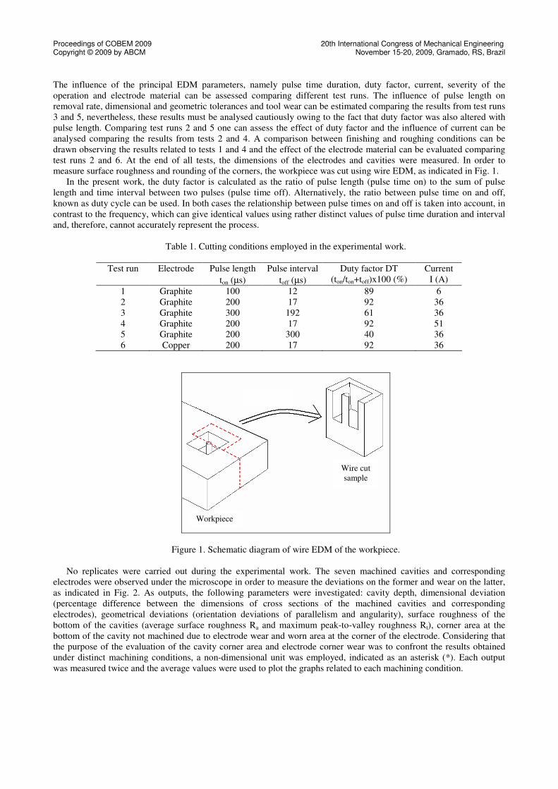
test runs 2 and 6. At the end of all tests, the dimensions of the electrodes and cavities were measured. In order to
measure surface roughness and rounding of the corners, the workpiece was cut using wire EDM, as indicated in Fig. 1.
In the present work, the duty factor is calculated as the ratio of pulse length (pulse time on) to the sum of pulse
length and time interval between two pulses (pulse time off). Alternatively, the ratio between pulse time on and off,
known as duty cycle can be used. In both cases the relationship between pulse times on and off is taken into account, in
contrast to the frequency, which can give identical values using rather distinct values of pulse time duration and interval
and, therefore, cannot accurately represent the process.
Table 1. Cutting conditions employed in the experimental work.
Test run Electrode Pulse length
ton (µs)
Pulse interval
toff (µs)
Duty factor DT
(ton/ton+toff)x100 (%)
Current
I (A)
1 Graphite 100 12 89 6
2 Graphite 200 17 92 36
3 Graphite 300 192 61 36
4 Graphite 200 17 92 51
5 Graphite 200 300 40 36
6 Copper 200 17 92 36
Figure 1. Schematic diagram of wire EDM of the workpiece.
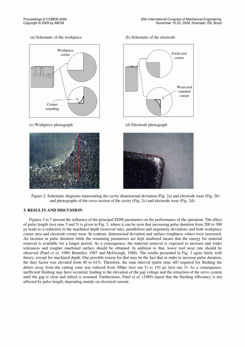
No replicates were carried out during the experimental work. The seven machined cavities and corresponding
electrodes were observed under the microscope in order to measure the deviations on the former and wear on the latter,
as indicated in Fig. 2. As outputs, the following parameters were investigated: cavity depth, dimensional deviation
(percentage difference between the dimensions of cross sections of the machined cavities and corresponding
electrodes), geometrical deviations (orientation deviations of parallelism and angularity), surface roughness of the
bottom of the cavities (average surface roughness Ra and maximum peak-to-valley roughness Rt), corner area at the
bottom of the cavity not machined due to electrode wear and worn area at the corner of the electrode. Considering that
the purpose of the evaluation of the cavity corner area and electrode corner wear was to confront the results obtained
under distinct machining conditions, a non-dimensional unit was employed, indicated as an asterisk (*). Each output
was measured twice and the average values were used to plot the graphs related to each machining condition.
Workpiece
Wire cut
sample
Proceedings of COBEM 2009 20th International Congress of Mechanical Engineering Copyright © 2009 by ABCM November 15-20, 2009, Gramado, RS, Brazil
(a) Schematic of the workpiece (b) Schematic of the electrode
(c) Workpiece photograph (d) Electrode photograph
Figure 2. Schematic diagrams representing the cavity dimensional deviation (Fig. 2a) and electrode wear (Fig. 2b)
and photographs of the cross section of the cavity (Fig. 2c) and electrode wear (Fig. 2d).
3. RESULTS AND DISCUSSION
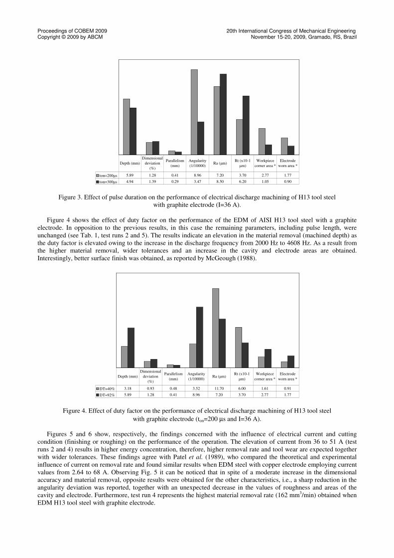
Figures 3 to 7 present the influence of the principal EDM parameters on the performance of the operation. The effect
of pulse length (test runs 3 and 5) is given in Fig. 3, where it can be seen that increasing pulse duration from 200 to 300
µs leads to a reduction in the machined depth (removal rate), parallelism and angularity deviations and both workpiece
corner area and electrode corner wear. In contrast, dimensional deviation and surface roughness values were increased.
An increase in pulse duration while the remaining parameters are kept unaltered means that the energy for material
removal is available for a longer period. As a consequence, the material removal is expected to increase and wider
tolerances and rougher machined surface should be obtained. In addition to that, lower tool wear rate should be
observed (Patel et al. 1989; Benedict, 1987 and McGeough, 1988). The results presented in Fig. 3 agree fairly with
theory, except for machined depth. One possible reason for that may be the fact that in order to increase pulse duration,
the duty factor was elevated from 40 to 61%. Therefore, the time interval (pulse time off) required for flushing the
debris away from the cutting zone was reduced from 300µs (test run 5) to 192 µs (test run 3). As a consequence,
inefficient flushing may have occurred, leading to the elevation of the gap voltage and the retraction of the servo system
until the gap is clear and infeed is resumed. Furthermore, Patel et al. (1989) report that the flushing efficiency is not
affected by pulse length, depending mainly on electrical current.
Workpiece
corner
Corner
rounding
Worn tool
rounded
corner
Fresh tool
corner
Proceedings of COBEM 2009 20th International Congress of Mechanical Engineering Copyright © 2009 by ABCM November 15-20, 2009, Gramado, RS, Brazil
Figure 3. Effect of pulse duration on the performance of electrical discharge machining of H13 tool steel
with graphite electrode (I=36 A).
Figure 4 shows the effect of duty factor on the performance of the EDM of AISI H13 tool steel with a graphite
electrode. In opposition to the previous results, in this case the remaining parameters, including pulse length, were
unchanged (see Tab. 1, test runs 2 and 5). The results indicate an elevation in the material removal (machined depth) as
the duty factor is elevated owing to the increase in the discharge frequency from 2000 Hz to 4608 Hz. As a result from
the higher material removal, wider tolerances and an increase in the cavity and electrode areas are obtained.
Interestingly, better surface finish was obtained, as reported by McGeough (1988).
Figure 4. Effect of duty factor on the performance of electrical discharge machining of H13 tool steel
with graphite electrode (ton=200 µs and I=36 A).
Figures 5 and 6 show, respectively, the findings concerned with the influence of electrical current and cutting
condition (finishing or roughing) on the performance of the operation. The elevation of current from 36 to 51 A (test
runs 2 and 4) results in higher energy concentration, therefore, higher removal rate and tool wear are expected together
with wider tolerances. These findings agree with Patel et al. (1989), who compared the theoretical and experimental
influence of current on removal rate and found similar results when EDM steel with copper electrode employing current
values from 2.64 to 68 A. Observing Fig. 5 it can be noticed that in spite of a moderate increase in the dimensional
accuracy and material removal, opposite results were obtained for the other characteristics, i.e., a sharp reduction in the
angularity deviation was reported, together with an unexpected decrease in the values of roughness and areas of the
cavity and electrode. Furthermore, test run 4 represents the highest material removal rate (162 mm3/min) obtained when
EDM H13 tool steel with graphite electrode.
ton=200µs 5.89 1.28 0.41 8.96 7.20 3.70 2.77 1.77
ton=300µs 4.94 1.39 0.29 3.47 8.50 6.20 1.05 0.90
Depth (mm)
Dimensional
deviation
(%)
Parallelism
(mm)
Angularity
(1/10000)Ra (µm)
Rt (x10-1
µm)
Workpiece
corner area *
Electrode
worn area *
DT=40% 3.18 0.93 0.48 3.52 11.70 6.00 1.61 0.91
DT=92% 5.89 1.28 0.41 8.96 7.20 3.70 2.77 1.77
Depth (mm)
Dimensional
deviation
(%)
Parallelism
(mm)
Angularity
(1/10000)Ra (µm)
Rt (x10-1
µm)
Workpiece
corner area *
Electrode
worn area *

Proceedings of COBEM 2009 20th International Congress of Mechanical Engineering Copyright © 2009 by ABCM November 15-20, 2009, Gramado, RS, Brazil
Figure 5. Effect of current on the performance of electrical discharge machining of H13 tool steel
with graphite electrode (ton=200 µs and DT=92%).
Comparing finish and rough EDM operations, see Figure 6 (test runs 1 and 4), it can be noted that when roughing
parameters are selected the machined depth (material removal) increases drastically owing to the energy available for
melting and vaporizing the work material. Consequently, poorer surface finish is obtained, as indicated by the Ra and Rt
values. In addition to that, higher tool wear is observed and, as a result, the rounding at the bottom of the cavity is
increased. Nevertheless, tighter dimensional and geometric deviations were obtained under the roughing condition. It is
important to point out that when switching from finish to rough EDM all three parameters (pulse duration, duty factor
and current) are changed, therefore, the effect of each factor cannot be assessed separately.
Figure 6. Effect of the cutting condition on the performance of electrical discharge machining of H13 tool steel
with graphite electrode.
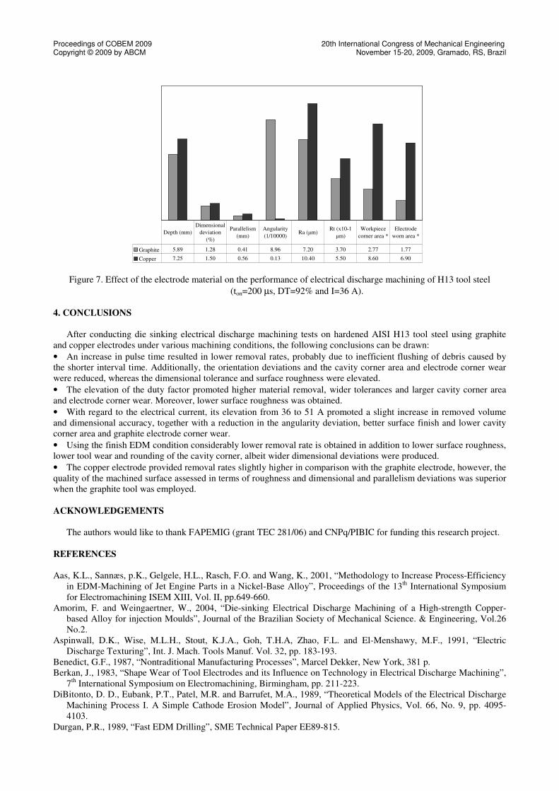
Finally, the results related to the influence of the electrode material on the performance of the operation are
presented in Figure 7 (test runs 2 and 6). These findings suggest that the copper electrode provides superior material
removal (machined depth) together with tighter angularity deviation, whereas the graphite electrode was responsible for
closer dimensional and parallelism deviations, lower surface roughness and smaller workpiece corner area and electrode
corner wear. According to McGeough (1988), copper electrodes allow high material removal rates and are highly stable
in sparking, providing, for some work materials, superior surface finish than graphite. In the present work, the highest
material removal rate (187 mm3/min) was obtained using the copper electrode (test run 6), in spite of the fact that a
considerably lower current was employed in comparison to test run 4 carried out using graphite electrode (36 A against
51 A). On the other hand, the higher melting point of graphite results in lower electrode wear.
I=36A 5.89 1.28 0.41 8.96 7.20 3.70 2.77 1.77
I=51A 6.27 1.35 0.32 0.17 5.90 3.15 2.46 0.66
Depth (mm)Dimensional
deviation (%)
Parallelism
(mm)
Angularity
(1/10000)Ra (µm)
Rt (x10-1
µm)
Workpiece
corner area *
Electrode
worn area *
Finishing 0.51 3.20 0.59 7.37 5.30 2.70 0.58 0.51
Roughing 6.27 1.35 0.32 0.17 5.90 3.15 2.46 0.66
Depth (mm)
Dimensional
deviation
(%)
Parallelism
(mm)
Angularity
(1/10000)Ra (µm)
Rt (x10-1
µm)
Workpiece
corner area *
Electrode
worn area *
Finishing: ton=100 µs, DT=89% and I=6 A
Roughing: ton=200 µs, DT=92% and I=51 A
Proceedings of COBEM 2009 20th International Congress of Mechanical Engineering Copyright © 2009 by ABCM November 15-20, 2009, Gramado, RS, Brazil
Figure 7. Effect of the electrode material on the performance of electrical discharge machining of H13 tool steel
(ton=200 µs, DT=92% and I=36 A).
4. CONCLUSIONS
After conducting die sinking electrical discharge machining tests on hardened AISI H13 tool steel using graphite
and copper electrodes under various machining conditions, the following conclusions can be drawn:
• An increase in pulse time resulted in lower removal rates, probably due to inefficient flushing of debris caused by
the shorter interval time. Additionally, the orientation deviations and the cavity corner area and electrode corner wear
were reduced, whereas the dimensional tolerance and surface roughness were elevated.
• The elevation of the duty factor promoted higher material removal, wider tolerances and larger cavity corner area
and electrode corner wear. Moreover, lower surface roughness was obtained.
• With regard to the electrical current, its elevation from 36 to 51 A promoted a slight increase in removed volume
and dimensional accuracy, together with a reduction in the angularity deviation, better surface finish and lower cavity
corner area and graphite electrode corner wear.
• Using the finish EDM condition considerably lower removal rate is obtained in addition to lower surface roughness,
lower tool wear and rounding of the cavity corner, albeit wider dimensional deviations were produced.
• The copper electrode provided removal rates slightly higher in comparison with the graphite electrode, however, the
quality of the machined surface assessed in terms of roughness and dimensional and parallelism deviations was superior
when the graphite tool was employed.
ACKNOWLEDGEMENTS
The authors would like to thank FAPEMIG (grant TEC 281/06) and CNPq/PIBIC for funding this research project.
REFERENCES
Aas, K.L., Sannæs, p.K., Gelgele, H.L., Rasch, F.O. and Wang, K., 2001, “Methodology to Increase Process-Efficiency
in EDM-Machining of Jet Engine Parts in a Nickel-Base Alloy”, Proceedings of the 13th
International Symposium
for Electromachining ISEM XIII, Vol. II, pp.649-660.
Amorim, F. and Weingaertner, W., 2004, “Die-sinking Electrical Discharge Machining of a High-strength Copper-
based Alloy for injection Moulds”, Journal of the Brazilian Society of Mechanical Science. & Engineering, Vol.26
No.2.
Aspinwall, D.K., Wise, M.L.H., Stout, K.J.A., Goh, T.H.A, Zhao, F.L. and El-Menshawy, M.F., 1991, “Electric
Discharge Texturing”, Int. J. Mach. Tools Manuf. Vol. 32, pp. 183-193.
Benedict, G.F., 1987, “Nontraditional Manufacturing Processes”, Marcel Dekker, New York, 381 p.
Berkan, J., 1983, “Shape Wear of Tool Electrodes and its Influence on Technology in Electrical Discharge Machining”,
7th
International Symposium on Electromachining, Birmingham, pp. 211-223.
DiBitonto, D. D., Eubank, P.T., Patel, M.R. and Barrufet, M.A., 1989, “Theoretical Models of the Electrical Discharge
Machining Process I. A Simple Cathode Erosion Model”, Journal of Applied Physics, Vol. 66, No. 9, pp. 4095-
4103.
Durgan, P.R., 1989, “Fast EDM Drilling”, SME Technical Paper EE89-815.
Graphite 5.89 1.28 0.41 8.96 7.20 3.70 2.77 1.77
Copper 7.25 1.50 0.56 0.13 10.40 5.50 8.60 6.90
Depth (mm)
Dimensional
deviation
(%)
Parallelism
(mm)
Angularity
(1/10000)Ra (µm)
Rt (x10-1
µm)
Workpiece
corner area *
Electrode
worn area *
Proceedings of COBEM 2009 20th International Congress of Mechanical Engineering Copyright © 2009 by ABCM November 15-20, 2009, Gramado, RS, Brazil
Eubank, P.T., Patel, M.R., Barrufet, M.A., Bozkurt, B., 1993, “Theoretical Models of the Electrical Discharge
Machining Process III. The Variable Mass, Cylindrical Plasma Mode”, Journal of Applied Physics, Vol. 73, No. 11,
pp. 7900-7909.
Guitrau, E.P., 1997, “The EDM Handbook”, Hanser Gardner Publications, Cincinnati, U.S.A.
Iwai, Y., Hiroi, M. and Nakano, M., 2001, “ Investigation of EDM Machining States Using Ultrasonic Waves
“,Proceedings of the 13th
International Symposium for Electromachining ISEM XIII, Vol. 1 , pp.109-116.
Jameson, E.C., 2001, “Electrical Discharge Machining”, Society of Manufacturing Engineers, Michigan, U.S.A.
Leão, F.N., Pashby, I. R., Cuttell, M. and Lord, P., 2005, “Optimisation of EDM Fast Hole-Drilling through Evaluation
of Dielectric and Electrode Materials”, Proceedings of the 18th International Congress of Mechanical Engineering
(COBEM), Ouro Preto, MG, Brazil.
Lee, S.H. and Li, X.P., 2001, “Study of the Effect of Machining Parameters on the Machining Characteristics in
Electrical Discharge Machining of Tungsten Carbide”, Journal of Materials Processing Technology, Vol. 115, pp.
344-358.
Li, S.C. and Hon, K.K.B., 1994, “Experimental Study of Electrode Build-up Phenomenon in EDM”, EDM Technology,
Vol. 2, pp. 42-46.
Luo, Y.F., 1998, “An Evaluation of Spark Mobility in Electrical Discharge Machining”, IEE Transactions on Plasma
Science, Vol. 26, No. 3, pp.1010-1016.
Masuzawa, T., 2001, “Micro-EDM”, Proceedings of the 13th
International Symposium for Electromachining ISEM
XIII, Vol. 1, pp.3-19.
McGeough, J.A., 1988, “Advanced Methods of Machining”, Chapman and Hall, London, 247 p.
Minami, H., Masui, K., Tsukahara, H. and Hagino, H., 2001, “Coloring of Titanium Alloy using EDM Process –
Drawing with Simple Electrode”, Proceedings of the 13th
International Symposium for Electromachining ISEM
XIII, Vol. II, pp.589-599.
Mohan, B., Rajadurai, A. and Satyanarayana, K.G., 2004, “Electric Discharge Machining of Al-SiC Metal Matrix
Composites Using Rotary Tube Electrode”, Journal of Machining Processing Technology, Vol. 153-154, pp.978-
985.
Mohri, N., Suzuki, M., Masanori, F. and Nagao, S., 1995, “Electrode Wear Process in Electrical Discharge Machining”,
Annals of the CIRP, Vol. 44/1, pp.165-168.
Niwa, S., and Furuya, M., 1995, “A Study on Optimum Machining Conditions in EDM Process for making Molds and
Dies”, Proceedings of the 11st International Symposium for Electromachining ISEM XI, Lausanne, Switzerland, pp.
325-332.
Patel, M.R., Barrufet, M.A., Eubank, P.T., DiBitonto, D.D., 1989, “Theoretical Models of the Electrical Discharge
Machining Process II. The Anode Erosion Model”, Journal of Applied Physics, Vol. 66, No. 9, pp. 4104-4111.
Rooij, N.F., 1995, “Silicon Micromachining as a Basis for Micro systems Developments”, Proceedings of the 11st.
International Symposium for Electromachining ISEM -XI, Lausanne, Switzerland, pp. 61-64.
Singh, U.P., Miller, P.P. and Urquhart, W., 1985, “The Influence of Electro-Discharge Machining Parameters on
Machining Characteristics”, Proceedings of the International Machine Tool Design e Research Conference,
Manchester, UK, Vol. 25, pp. 337-345.
Sommer, C., 2000, “Non-Traditional Machining Handbook“, Advance Publishing, Houston, USA.
Spur, G. and Schönbeck, J., 1993, “Anode Erosion in Wire –EDM – A Theoretical Model”, Annals of the CIRP, Vol.
42/1, pp.253-256.
Storr, M., 1999, “Important Facts About Spark Erosion, OEL-HELD GmbH, Germany.
Thoe, T.B., Aspinwall, D.K., Wise, M.l.H. and Oxley, I.A., 1996, “Polycrystalline Diamond Edge quality and Surface
Integrity Following Electrical Discharge Griding”, Journal of Materials Processing Technology, Vol. 56, pp. 773-
785.
Tsai, H.C., Yan, B.H. and Huang, F.Y., 2003, “EDM Performance of Cr/Cu-based Composite Electrodes”, International
Journal of Machining Tools & Manufacture, Vol. 43, pp.245-252.
Tsai, Y. and Masuzawa, T.,2004, “An Index to Evaluate the Wear Resistance of the Electrode in Micro EDM”, Journal
of Machining Processing Technology, Vol. 149, pp.304-309.
Uno, Y., Okada, A., Hayashi, Y. and Tabuchi, Y., 1999, “Surface Modification by EDM with Nickel Powder Mixed
Fluid”, International Journal of Electrical Machining, no.4, pp. 47-52.
Van Roekel, N.B., 1992, “Electrical Discharge Machining in Dentistry”, The International Journal of Prosthodontics,
Vol. 5/2, pp. 114-121.
Wijers, J.L.C., 1991, “EDM Drilling Picks up Speed”, Modern Machine Shop, June Edition, pp.56-66.
RESPONSIBILITY NOTICE
The authors are the only responsible for the printed material included in this paper.