the inspector q1, 2013 - skf.com12-122935/skf microlog inspector...2013 ‘q1 skf microlog inspector...
TRANSCRIPT
SKF Microlog Inspector Newsletter Q1 2013
SKF Microlog Inspector Newsletter Q1, 2013
A Passion for Reliability
By John Yolton
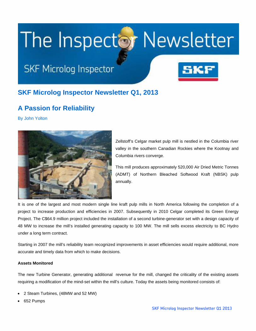
Zellstoff’s Celgar market pulp mill is nestled in the Columbia river
valley in the southern Canadian Rockies where the Kootnay and
Columbia rivers converge.
This mill produces approximately 520,000 Air Dried Metric Tonnes
(ADMT) of Northern Bleached Softwood Kraft (NBSK) pulp
annually.
It is one of the largest and most modern single line kraft pulp mills in North America following the completion of a
project to increase production and efficiencies in 2007. Subsequently in 2010 Celgar completed its Green Energy
Project. The C$64.9 million project included the installation of a second turbine-generator set with a design capacity of
48 MW to increase the mill’s installed generating capacity to 100 MW. The mill sells excess electricity to BC Hydro
under a long term contract.
Starting in 2007 the mill’s reliability team recognized improvements in asset efficiencies would require additional, more
accurate and timely data from which to make decisions.
Assets Monitored
The new Turbine Generator, generating additional revenue for the mill, changed the criticality of the existing assets
requiring a modification of the mind-set within the mill’s culture. Today the assets being monitored consists of:
2 Steam Turbines, (48MW and 52 MW)
652 Pumps
SKF Microlog Inspector Newsletter Q1 2013
8675 Electric Motors and 6 Hydraulic motors
456 Gearboxes
4 Compressors
Lots of process rolls, in both slow and variable speed applications
Technology Deployed
Machinery health information is derived from the following technologies:
Condition monitoring system,
o SKF @ptitude Monitoring Suite
@ptitude Analyst, (Route Based, and wireless)
@ptitude Monitor, (DMx’s)
@ptitude Inspector (ODR)
@ptitude Decision Support (@DS)
MOPS, DCS process data/ Data historian
Avantis CMMS system integration with @DS
Root cause analysis, (Apollo),
Operating Investigation Reports, (OIR)
ESSO’s EPLUS lubrication software
The Process
Involving operators in collecting condition monitoring data was essential to the program’s success as the Operator
Driven Reliability (ODR) process routinely monitored specified critical equipment on a shift-by-shift, daily basis.
Five (5) SKF Microlog Inspectors are in use within the Pulp Dryers (2), Recaust and Wood Room areas, with the
Digester area next following recommendations derived from the SKF RCM (SRCM) study.
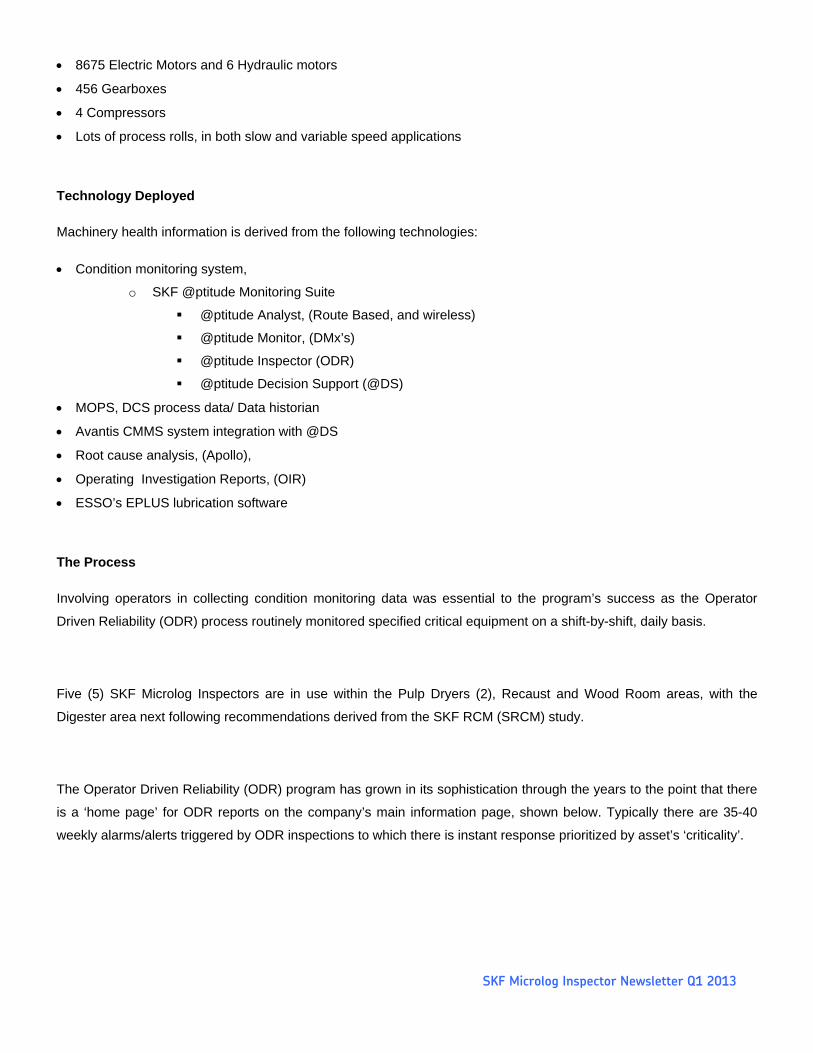
The Operator Driven Reliability (ODR) program has grown in its sophistication through the years to the point that there
is a ‘home page’ for ODR reports on the company’s main information page, shown below. Typically there are 35-40
weekly alarms/alerts triggered by ODR inspections to which there is instant response prioritized by asset’s ‘criticality’.
SKF Microlog Inspector Newsletter Q1 2013
This ‘game-changing’ process has resulted in a role change for the PdM analysts from one of collecting data on time-
based routes to much needed maintenance of the asset database and follow through on reported events found through
the ODR program and the installed online monitoring systems.
Case History
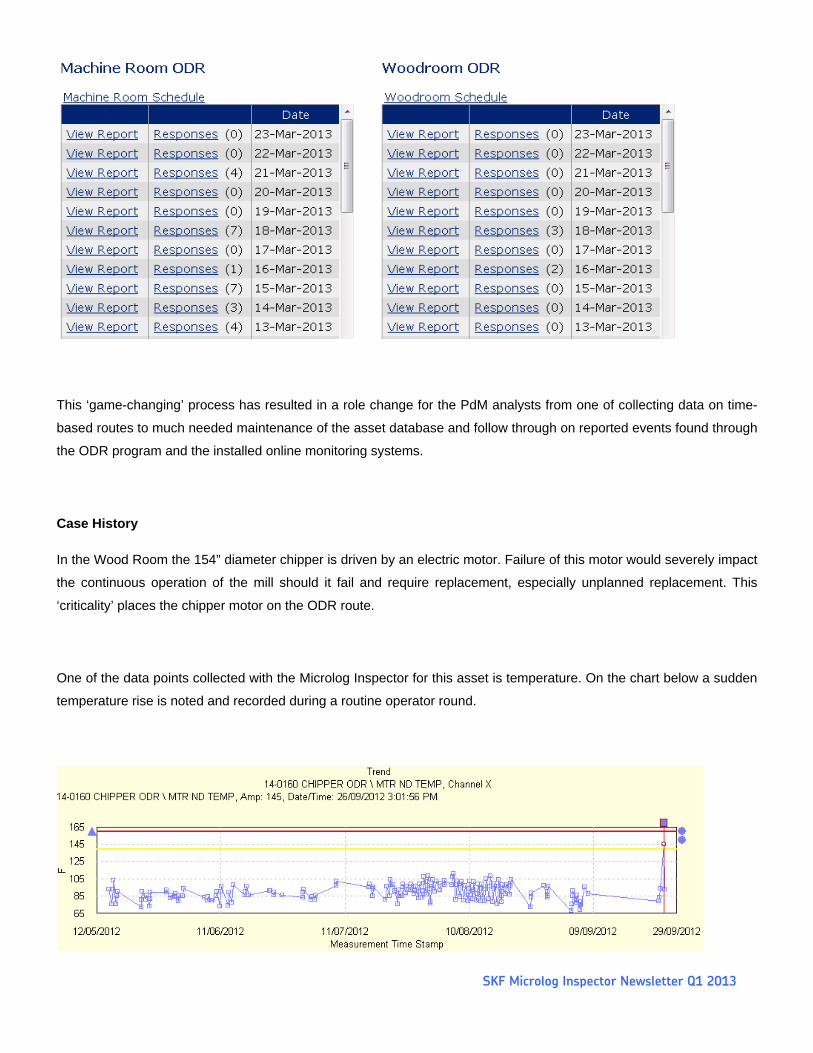
In the Wood Room the 154” diameter chipper is driven by an electric motor. Failure of this motor would severely impact
the continuous operation of the mill should it fail and require replacement, especially unplanned replacement. This
‘criticality’ places the chipper motor on the ODR route.
One of the data points collected with the Microlog Inspector for this asset is temperature. On the chart below a sudden
temperature rise is noted and recorded during a routine operator round.
SKF Microlog Inspector Newsletter Q1 2013
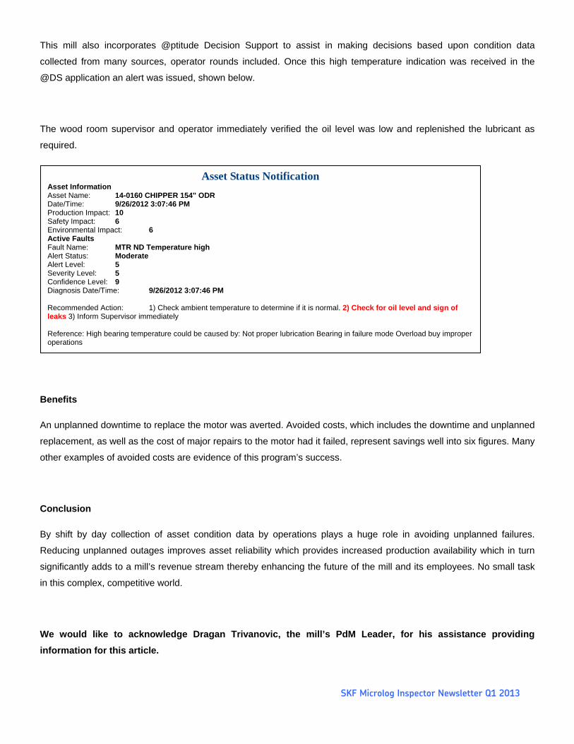
This mill also incorporates @ptitude Decision Support to assist in making decisions based upon condition data
collected from many sources, operator rounds included. Once this high temperature indication was received in the
@DS application an alert was issued, shown below.
The wood room supervisor and operator immediately verified the oil level was low and replenished the lubricant as
required.
Benefits
An unplanned downtime to replace the motor was averted. Avoided costs, which includes the downtime and unplanned
replacement, as well as the cost of major repairs to the motor had it failed, represent savings well into six figures. Many
other examples of avoided costs are evidence of this program’s success.
Conclusion
By shift by day collection of asset condition data by operations plays a huge role in avoiding unplanned failures.
Reducing unplanned outages improves asset reliability which provides increased production availability which in turn
significantly adds to a mill’s revenue stream thereby enhancing the future of the mill and its employees. No small task
in this complex, competitive world.
We would like to acknowledge Dragan Trivanovic, the mill’s PdM Leader, for his assistance providing
information for this article.
Asset Status Notification Asset Information Asset Name: 14-0160 CHIPPER 154" ODR Date/Time: 9/26/2012 3:07:46 PM Production Impact: 10 Safety Impact: 6 Environmental Impact: 6 Active Faults Fault Name: MTR ND Temperature high Alert Status: Moderate Alert Level: 5 Severity Level: 5 Confidence Level: 9 Diagnosis Date/Time: 9/26/2012 3:07:46 PM Recommended Action: 1) Check ambient temperature to determine if it is normal. 2) Check for oil level and sign of leaks 3) Inform Supervisor immediately Reference: High bearing temperature could be caused by: Not proper lubrication Bearing in failure mode Overload buy improper operations

2013 ‘Q1 SKF Microlog Inspector Newsletter |
PSM (Process Safety Management) Inspections by Joe Schoultheis
Unexpected releases of toxic, reactive, or flammable liquids and gases in processes involving highly hazardous
chemicals have been reported for many years in various industries that use chemicals with such properties.
Regardless of the industry that uses these highly hazardous chemicals, there is a potential for an accidental release
any time they are not properly controlled, creating the possibility of disaster.
To help assure safe and healthy
workplaces, OSHA has issued the
Process Safety Management of Highly
Hazardous Chemicals regulation (Title
29 of CFR Section 1910.119) which
contains requirements for the
management of hazards associated with
processes using highly hazardous
chemicals. Many countries across the
world have similar regulations. [1]
Any facility that stores or uses a defined
"highly hazardous chemical" must
comply with OSHA's process safety management (PSM) regulations, as well as the quite similar United States
Environmental Protection Agency (EPA) Risk management program (RMP) regulations (Title 40 CFR Part 68). The
EPA has published a model RMP plan for an ammonia refrigeration facility, which provides excellent guidance on how
to comply with either OSHA's PSM regulations or the EPA's RMP regulations.
Why did OSHA develop PSM regulations? Bhopal, India (1984) 2,000 deaths from an Isocyanine release; Pasadena
Texas (1989) 23 deaths and 132 injuries from a petroleum explosion; Cincinnati Ohio (1990) 2 deaths from explosion;
Sterlington LA (1991) 8 deaths, 128 injured – chemical release. A great many industrial facilities must comply with
OSHA’s PSM regulations as well as quite similar EPA Risk Management Program regulations.
Fines issued to companies using highly hazardous chemicals who were found to be non-compliant run in the hundreds of thousands and even millions of dollars.
Where do companies start to develop a PSM inspection program? Process safety information Identify the hazards of the chemicals used
Identify the equipment that uses the chemicals
Employee involvement
2013 ‘Q1 SKF Microlog Inspector Newsletter |
Mechanical integrity of the equipment Written procedures for inspections
Inspections and testing
Quality assurances
Compliance Audits Planning for regularly scheduled inspections Staffing Conduct the audit Evaluation and corrective action Where does Microlog Inspector fit into this?
Tracking the chemicals and equipment used in the Process
Employee involvement
Written procedures
Inspection and testing
Quality assurances
Compliance audits o Planning and scheduling
o Staffing
o Conducting the audit
o Evaluation and corrective action
o Documentation, reports
How did one company start their PSM inspections? Very large air coolers are used at the plant for their refrigeration process with ammonia.
Maintenance instructions were obtained
A formal RCM (Reliability Centered Maintenance ) based on WCM (World Class Manufacturing) Principles was
developed
Each asset requiring inspection was identified, numbered, named, failure mode identified, inspection task defined,
frequency, inspection time. For example:
Item 1.0 – Niagara Evap Condenser Panels #1 Inspect for Leak
PSM Task: Through a walk-about inspection slowly walk around the unit asset with an awareness for
any signs of ammonia smell. If detected quickly vacate the area and alert management/supervisor.
2013 ‘Q1 SKF Microlog Inspector Newsletter |
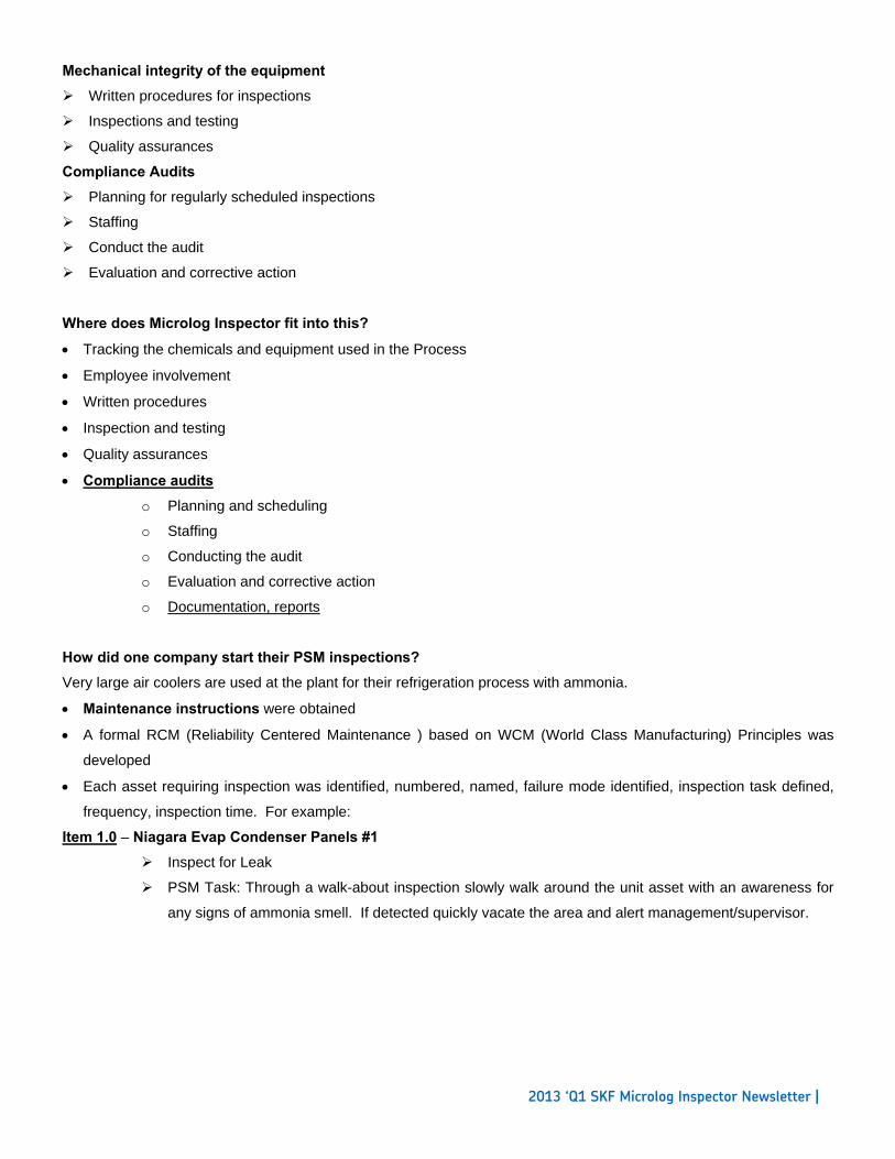
The problem was – from this one asset, 38 Job Plans were created and loaded in the CMMS!
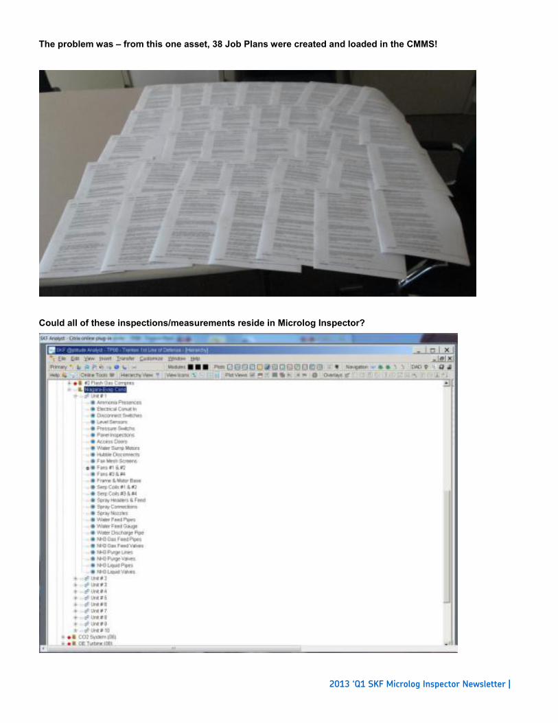
Could all of these inspections/measurements reside in Microlog Inspector?
2013 ‘Q1 SKF Microlog Inspector Newsletter |
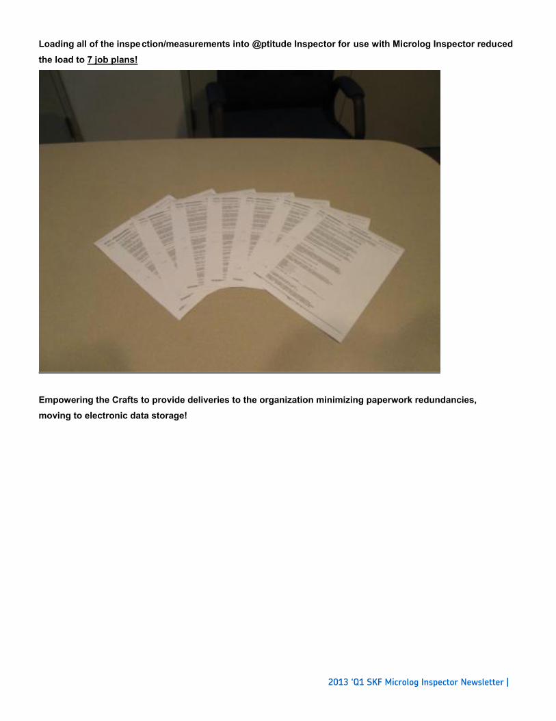
Loading all of the inspection/measurements into @ptitude Inspector for use with Microlog Inspector reduced the load to 7 job plans!
Empowering the Crafts to provide deliveries to the organization minimizing paperwork redundancies, moving to electronic data storage!
2013 ‘Q1 SKF Microlog Inspector Newsletter |
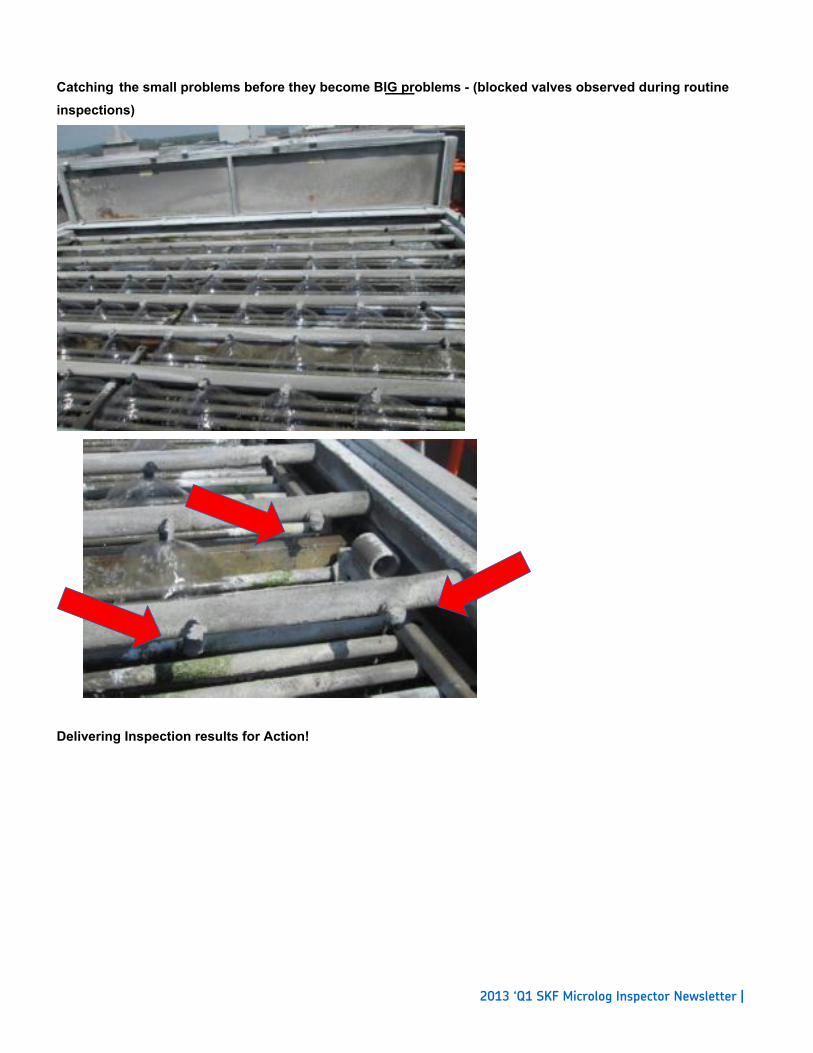
Catching the small problems before they become BIG problems - (blocked valves observed during routineinspections)
Delivering Inspection results for Action!

2013 ‘Q1 SKF Microlog Inspector Newsletter |
Corroded pipes identified through frequency inspection allowing for planned project replacement before any failure.
[1] Source – http://www.osha.gov
2013 ‘Q1 SKF Microlog Inspector Newsletter |
Connecting Microlog Inspector to Cloud Services By Alex Pinkerton
One of the confusions we’ve come across on a number of occasions is that of getting a Microlog Inspector handheld to
communicate with the @ptitude Cloud Services (RDC).
Everything seems to be set up and running. The @ptitude client is running, hierarchy data is visible, the Microlog
Inspector licenses are all properly installed, and yet, every attempt to connect Microlog Inspector to the Microlog
Service fails!
So why is this and what can Customers and SKF Service Engineers do to resolve this issue?
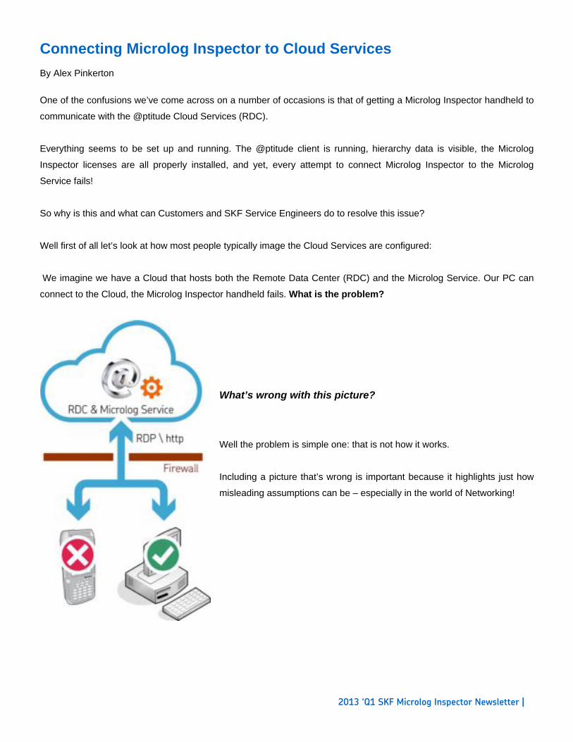
Well first of all let’s look at how most people typically image the Cloud Services are configured:
We imagine we have a Cloud that hosts both the Remote Data Center (RDC) and the Microlog Service. Our PC can
connect to the Cloud, the Microlog Inspector handheld fails. What is the problem?
What’s wrong with this picture?
Well the problem is simple one: that is not how it works.
Including a picture that’s wrong is important because it highlights just how
misleading assumptions can be – especially in the world of Networking!
2013 ‘Q1 SKF Microlog Inspector Newsletter |
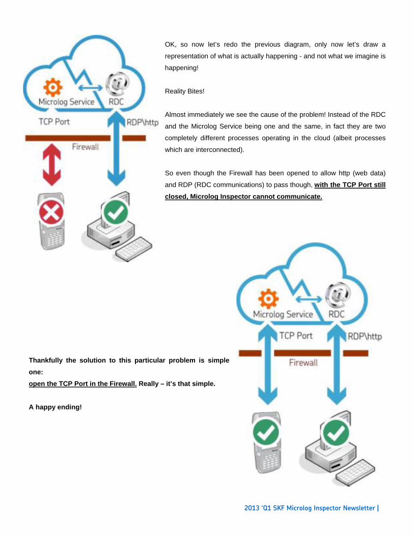
OK, so now let’s redo the previous diagram, only now let’s draw a
representation of what is actually happening - and not what we imagine is
happening!
Reality Bites!
Almost immediately we see the cause of the problem! Instead of the RDC
and the Microlog Service being one and the same, in fact they are two
completely different processes operating in the cloud (albeit processes
which are interconnected).
So even though the Firewall has been opened to allow http (web data)
and RDP (RDC communications) to pass though, with the TCP Port still
closed, Microlog Inspector cannot communicate.
Thankfully the solution to this particular problem is simple
one:
open the TCP Port in the Firewall. Really – it’s that simple.
A happy ending!

2013 ‘Q1 SKF Microlog Inspector Newsletter |
Automatic Valve Inspections By Charlie Unfricht ODR Applications Engineer
One component of plant efficienc y and reliability that is oft en overlooked is automatic valv es. They are typically the
domain of th e E&I depart ment in most facilities an d never re ally thought ab out by operatio n. But that d oesn’t mean
that there aren’t inspections production can do to help keep them reliable. Automatic valves can cause process upsets,
quality deviations and unscheduled downtime, among other th ings. So, doe s your In spection/ODR program include
valve inspections?
In this article I will outline some items the Microlog Inspector could be used to address.
Valve Inspection Questions:
Running
Is the valve leaking?
Loo se Bolts
Gasket leak
Valve body leaking/damaged
What is the air pressure to the I/P (current input to pressure output) converter?
Does it meet the valve manufacturer’s specifications?
What is the condition of the piping around the valve?
Lea ks
Han gers
Suppo rts
What is the condition of the air supply tubing/hose?
Loos e fittings
C racked/Leaking
Ru sting
Is there a water trap installed?
If yes is water building up?
Drain water and document how much was drained.
Positioner and I/P condition
Condition of pressure gauges
Positioner not securely mounted
Covers in place
Is the position indicator legible

2013 ‘Q1 SKF Microlog Inspector Newsletter |
Down
Verify valve strokes properly to the following percentages
25%/50%/75 %/100 %
Remove covers and inspect I/P and positioner for signs of rust etc.
Automatic valves can cost your facility a lot of money. I know of one automatic steam valve that was out of calibration.
The estimated annual savings for repai ring/re-calibrating this valve was $250,000. So if yo u answered no to valves
being part of your ODR process, you may want to consider the potential value of adding them.
If you have a topic related to applications for the Microlog Inspector, you would like discussed.
Please contact me at [email protected]
Thanks for reading.

2013 ‘Q1 SKF Microlog Inspector Newsletter |
Operator-Driven Reliability Best Practices Series: “Coping with innovation: No place for wimps!” By Dave Staples
Think about how often a mobile phone or personal computer is upgraded, every 2 or 3 years? Did you think this was a
ploy by the original equipment manufacturers (OEM) to make money? Maybe partly, but it is the only way to deliver the
latest technology. Every 2 to 5 years, there are major innovations for mobile devices in memory, processors,
performance, displays, durability, size, connectivity, and conveniences. So like it or not, innovations are coming and
probably faster than you want.
Very few people like unexpected change. To minimize the distress of technology changes, plans should be put in place
anticipating the fast moving technology window. In order for OEMs to deliver more hardware dependent features, like
WiFi, enhanced cameras, global positioning satellite (GPS), etc..., they need to change the hardware platform of the
mobile device.
The typical planned life cycle of a mobile device is 3 to 4 years. As users of mobile devices, a technology life cycle plan
should be every 4 to 5 years. There will also be incremental software updates throughout the product’s life cycle
bringing new features, fixing “bugs” and improving performance. These updates are usually installed via software down
loaded from an OEM website and are included in most maintenance or service agreements. These software updates
are typically not as much a financial burden as making a platform change with the device. Costs associated with
platform changes almost always require capital funding. And you know how much we all enjoy requesting capital
funding…
The ODR sustainability team needs to plan for both types of technology changes, hardware and software innovation.
The plan needs to incorporate the cost associated with the technology maintenance agreements and platform
upgrades. Plans must also include the human resources, in house or sub-contracted, necessary to rollout the
technology, “turn on and configure” new features, and train the users. It is pragmatic to recommend utilizing resources
experienced with the new technology to assist with these rollouts. Inexperienced support deploying new technology
can be inefficient and lead to rework. It all may sound fairly straight forward but there can be hidden details to the plan.
For example training material needs to be updated. Infrastructure may need to be installed, such as wireless
routers if going Wi-Fi for the first time. If new features introduce new inspections, work process
documentation may need to be updated.
Technology changes quickly. For companies staying in the forefront of ODR, this can be a good thing. Anticipating and
planning for technology updates and upgrades can help make these changes seemless.
2013 ‘Q1 SKF Microlog Inspector Newsletter |
What is coming up for Microlog Inspector? By Travis Bottalico
A new firmware version (v1.4.4) will be available soon to all Microlog Inspector customers, and we thought we’d give
an update on the features that are being included.
Camera Integration for the CMDM 6700 – Gives customers the ability to capture photos from within the Microlog
Inspector application.
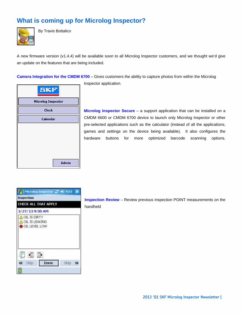
Microlog Inspector Secure – a support application that can be installed on a
CMDM 6600 or CMDM 6700 device to launch only Microlog Inspector or other
pre-selected applications such as the calculator (instead of all the applications,
games and settings on the device being available). It also configures the
hardware buttons for more optimized barcode scanning options.
Inspection Review – Review previous inspection POINT measurements on the
handheld
2013 ‘Q1 SKF Microlog Inspector Newsletter |
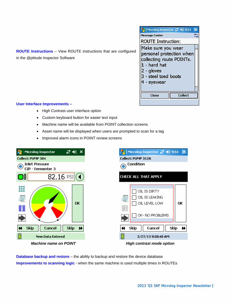
ROUTE Instructions – View ROUTE instructions that are configured
in the @ptitude Inspector Software
User Interface Improvements –
High Contrast user interface option
Custom keyboard button for easier text input
Machine name will be available from POINT collection screens
Asset name will be displayed when users are prompted to scan for a tag
Improved alarm icons in POINT review screens
Machine name on POINT High contrast mode option
Database backup and restore – the ability to backup and restore the device database
Improvements to scanning logic - when the same machine is used multiple times in ROUTEs
2013 ‘Q1 SKF Microlog Inspector Newsletter |
Stay informed with SMS Text messages or Simple Mail Transfer Protocol (SMTP) from @ptitude Inspector
By Robert Kaufman
The SKF @ptitude Inspector V7.0 software release has a great text and email feature that
can simplify the sharing of time sensitive information. The Simple Mail Transfer Protocol
(SMTP) is an Internet standard for email transmission across the Internet. It can operate
within a secure corporate environment to email just to employees within your company or
across the Internet using almost any common email service.
Once setup, this feature allows users to send or schedule notifications, email any generated
report, and configure the Scheduler application to perform actions in response to changes in
alarm conditions.
SMS (text) messages include the description of the alarm condition change in plain text, but
without the attached report. Email and SMS messages can be sent to an individual person,
or to groups of people. The email message format includes an HTML report along with
a .PDF attachment so that even members of your team without access to an account in the
SKF @ptitude Inspector software can receive timely and actionable information - that they
can open on almost any device.
The setup of your SKF @ptitude Inspector V7.0 SMTP connections are very easy to perform
provided that you can get some very basic SMTP server information from your company’s IT
provider.
In this article, I will focus on setting up the system to send messages within a corporate
network. This will allow you to access the corporate mail services from within any of your
company sites as long as they are within your companies firewall, or by connecting through
the approved VPN mechanism to the corporate network. This point is very important. If
the client application is located outside the company’s network, any attempts to connect to
the SMTP server using the SKF @ptitude Inspector Configuration Tool, or any attempts to
send messages using the application through the SKF SMTP server, will fail.
2013 ‘Q1 SKF Microlog Inspector Newsletter |
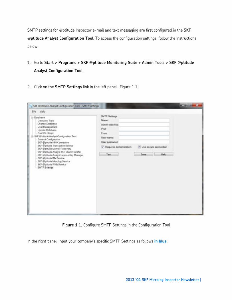
SMTP settings for @ptitude Inspector e-mail and text messaging are first configured in the SKF
@ptitude Analyst Configuration Tool. To access the configuration settings, follow the instructions
below:
1. Go to Start > Programs > SKF @ptitude Monitoring Suite > Admin Tools > SKF @ptitude
Analyst Configuration Tool.
2. Click on the SMTP Settings link in the left panel. [Figure 1.1]
Figure 1.1. Configure SMTP Settings in the Configuration Tool
In the right panel, input your company’s specific SMTP Settings as follows in blue:
2013 ‘Q1 SKF Microlog Inspector Newsletter |
Name: This name will appear in some e-mail clients receiving messages from @ptitude Inspector as the
name of the message sender. The Configuration Tool requires that this field be filled in. It can’t be left
empty:
Enter any name as desired
Server Address: This text value contains the network address of the SMTP server that the @ptitude
Inspector application should use to send e-mail messages. Depending on the environment where the
software is being installed, this server may be either an internal location within an organization’s private
network, or a publicized public location for an external provider of e-mail service such as Google Gmail
or Yahoo Mail. The address may be specified as either a domain name such as smtp.gmail.com, or as a
valid IP address such as 74.125.137.109. The Configuration Tool requires that this field be filled in as
well.
Type in the name of your server
Port: Contains the port number associated with enabling clients to access the SMTP server described
above. The right port number to use depends on how an SMTP server has been set up by its owner,
and will often be publicized for the benefit of authorized users. The Configuration Tool requires that this
field be filled in with a non-empty numeric integer value:
Type in the port number provided to you by your IT support; example: 25
From: This text value contains an e-mail address that may appear in some e-mail clients as the
originating address for messages that are sent from the SKF @ptitude Inspector application. The
Configuration Tool requires that this field be filled in with a non-empty numeric integer value:
Enter any syntactically correct e-mail address
2013 ‘Q1 SKF Microlog Inspector Newsletter |
User Name: Contains the user or login name part of the authentication credentials used by many
SMTP service providers to ensure that their services are only being used by authorized users. This field
is required to be filled in by the Configuration Tool only if the “Requires authentication” checkbox is
enabled:
(Leave this blank for internal mail setup)
User Password: Contains the password part of the authentication credentials used by many SMTP
service providers to ensure that their services are only being used by authorized users. This field is
required to be filled in by the Configuration Tool only if the “Requires authentication” checkbox is
enabled:
(Leave this blank)
Requires authentication: Authentication usually consists of a login name and password combination.
When this box is checked, the SKF @ptitude Inspector application will provide the user name and
password described above as credentials to the SMTP server for authentication purposes:
(Leave this box unchecked)
Use secure connection: This box must be checked if the SMTP server uses standard encryption
protocols to protect the security of sensitive information being passed over the network:
(Leave this box unchecked)
Click the Test button once complete and a dialog box will display asking for an e-mail address. Input the
email address where the test notification will be sent to. For simplicity, I used my own corporate email
message and then clicked send. Once you confirm that you received the message, continue to the
steps below:
2013 ‘Q1 SKF Microlog Inspector Newsletter |
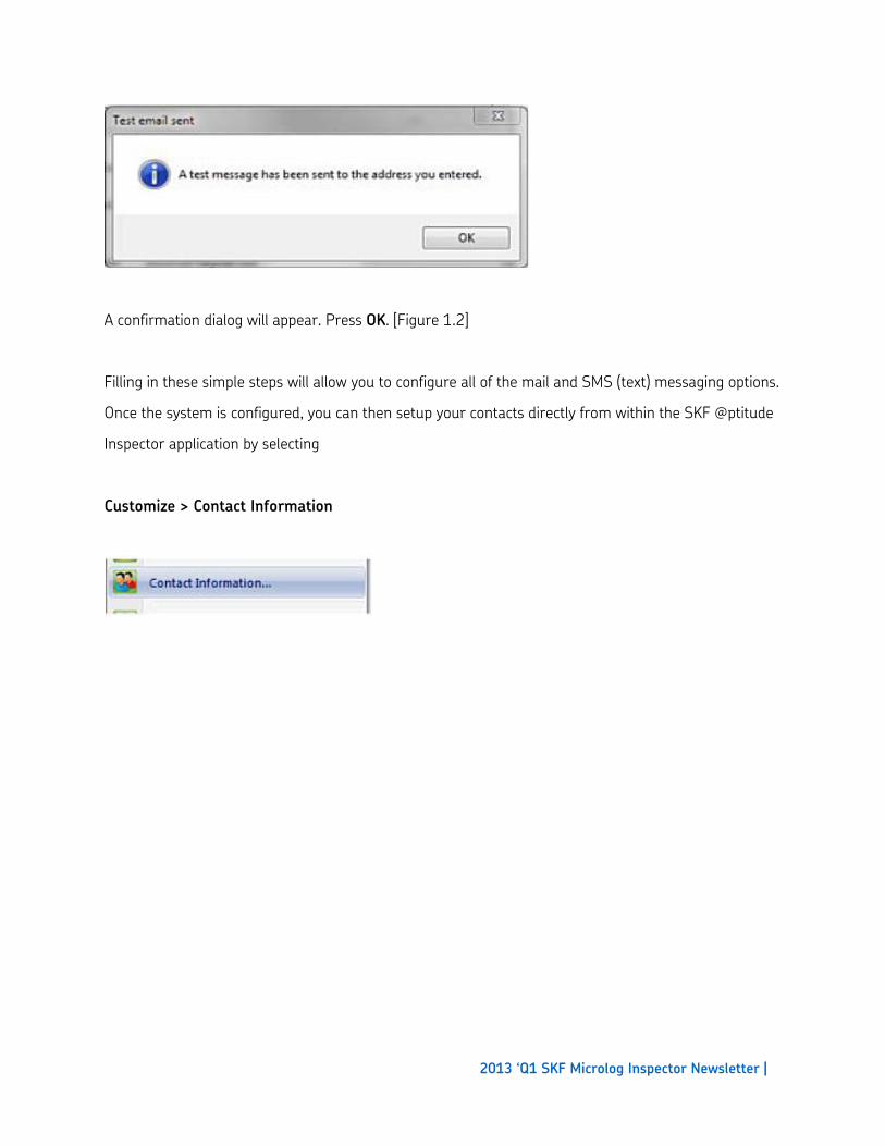
A confirmation dialog will appear. Press OK. [Figure 1.2]
Filling in these simple steps will allow you to configure all of the mail and SMS (text) messaging options.
Once the system is configured, you can then setup your contacts directly from within the SKF @ptitude
Inspector application by selecting
Customize > Contact Information