the interim runway visual range/automated surface ... · pdf fileinterim runway visual...
TRANSCRIPT

PREPARED BY:Communication, Navigation, and Surveillance Engineering Test DivisionWeather Branch--ACT-320Federal Aviation Administration William J. Hughes Technical CenterAtlantic City International AirportAtlantic City, NJ 08405
THE
INTERIM RUNWAY VISUAL RANGE/AUTOMATED SURFACE
OBSERVING SYSTEM INTERFACE
INSTRUCTION AND OPERATIONAL USER GUIDE
March 24, 1998
PREPARED FOR:Navigation and Landing Product Team, AND-740Federal Aviation Administration HeadquartersWashington, DC 20590
PREPARED FOR:INTERIM RVR/ASOS INTERFACE USERS

iii
TABLE OF CONTENTS
Page
OPERATIONAL USER GUIDE SUMMARY vii
1. INTRODUCTION 1
1.1 Hewlett Packard 200 LX Palmtop PC 11.2 Serial Data Cables 11.3 RS-232 to EIA-530 Level Converter 3
2. INTERIM RVR/ASOS INTERFACE INSTALLATION 3
3. INITIALIZING THE INTERIM RVR/ASOS INTERFACE 5
3.1 RVR System Configuration Settings 53.2 ASOS Configuration Settings 63.3 Hardware Connections 63.4 Executing HP Palmtop RVR-ASOS Software 6
4. INTERIM RVR/ASOS SHUTDOWN PROCEDURES 11
5. TECHNICAL SUPPORT 12
5.1 Maintenance Coordination Personnel 12
6. ACRONYMS 13
APPENDIXES
A - RVR and Interim RVR/ASOS Interface Maintenance Actions
B - HP Palmtop On-Screen Messages
C - Troubleshooting
D - Special Instructions
E - Internal Drive/PCMCIA Memory Card Directory Trees and File Contents
F – New Generation RVR MDT Screen Flowchart

v
LIST OF ILLUSTRATIONSFigure Page
1.2-1 Cable 1 21.2-2 Cable 2 21.2-3 Cable 3 21.3-1 Connections To/From Signal Level Converter 32-1 Interim RVR/ASOS Interface Connectivity 4

vii
OPERATIONAL USER GUIDE SUMMARY
The Interim Runway Visual Range/Automated Surface Observing System Interface (InterimRVR/ASOS Interface) Instruction and Operational User Guide is intended to inform users ofthe operational specifics for the Interim RVR/ASOS Interface. It is designed to allow users tobecome familiar with proper use of the interface to facilitate data transfer from the NewGeneration RVR System to ASOS at required locations. After reading this guide, usersshould be familiar with how to properly install, configure, start, and stop this interface, as wellas trouble-shoot most problems that may occur during usage.
Although not specifically addressed in this guide, it should be noted that communicationdistance limitations of the Interim RVR/ASOS Interface may create the need for additionalengineering at some locations. This guide addresses installations in which the distancebetween the RVR Data Processing Unit (DPU) and ASOS Acquisition Control Unit (ACU)are less than 4000 feet. Installations in which the distance between the RVR DPU and ASOSACU are greater than 4000 feet will require alternative communication media to ensuresuccessful data transfer. If the circumstances at your location require alternativecommunication media, please contact the RVR Program Office for additional assistance.Refer to section 5 for points of contact.
In the event content within this document should need revision, please contact:
FAA William J. Hughes Technical CenterWeather Branch, ACT-320Atlantic City International AirportAtlantic City, NJ 08405POC: Mike McKinneyPhone: (609) 485-5516
1
1. INTRODUCTION.
The Interim Runway Visual Range (RVR) /Automated Surface Observing System (ASOS)Interface includes components required to:
a. receive engineering data from the New Generation RVR system,b. convert engineering data to ASOS application data units (ADUs), andc. send ASOS ADUs to the ASOS Acquisition Control Unit (ACU).
These components are listed below and discussed in the following paragraphs:
d. Hewlett Packard 200 LX Palmtop PC,e. Serial Data Cables, andf. RS-232 to EIA-530 Level Converter.
1.1 HEWLETT PACKARD 200 LX PALMTOP PC.
The primary component of the Interim RVR/ASOS Interface is the Hewlett Packard 200LXPalmtop PC (HP Palmtop). As the name implies, the HP Palmtop is a small, hand-heldportable PC. The HP Palmtop operates with DOS version 5.0, internal RAM and data storage,and a 5- or 6-megabyte (MB) Personal Computer Memory Card International Association(PCMCIA) memory card which functions similar to a floppy disk in a standard PC.
The required software for your HP Palmtop has been installed on the internal disk andconfigured prior to shipment to your site. The PCMCIA memory card contains a backup copyof the RVR/ASOS application program, configuration files, and supporting utilities (refer toappendix E). The HP Palmtop also contains two rechargeable nicad batteries (refer toappendix D) and a 3-volt coin cell battery for backup.
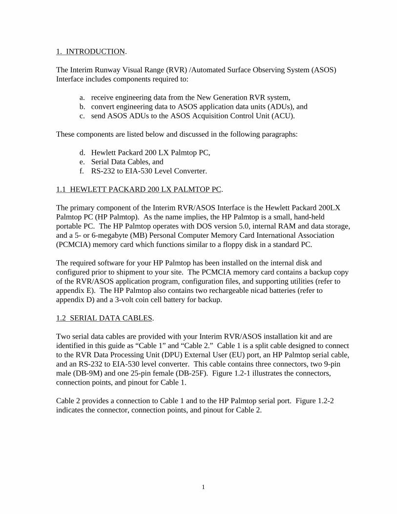
1.2 SERIAL DATA CABLES.
Two serial data cables are provided with your Interim RVR/ASOS installation kit and areidentified in this guide as “Cable 1” and “Cable 2.” Cable 1 is a split cable designed to connectto the RVR Data Processing Unit (DPU) External User (EU) port, an HP Palmtop serial cable,and an RS-232 to EIA-530 level converter. This cable contains three connectors, two 9-pinmale (DB-9M) and one 25-pin female (DB-25F). Figure 1.2-1 illustrates the connectors,connection points, and pinout for Cable 1.
Cable 2 provides a connection to Cable 1 and to the HP Palmtop serial port. Figure 1.2-2indicates the connector, connection points, and pinout for Cable 2.
2
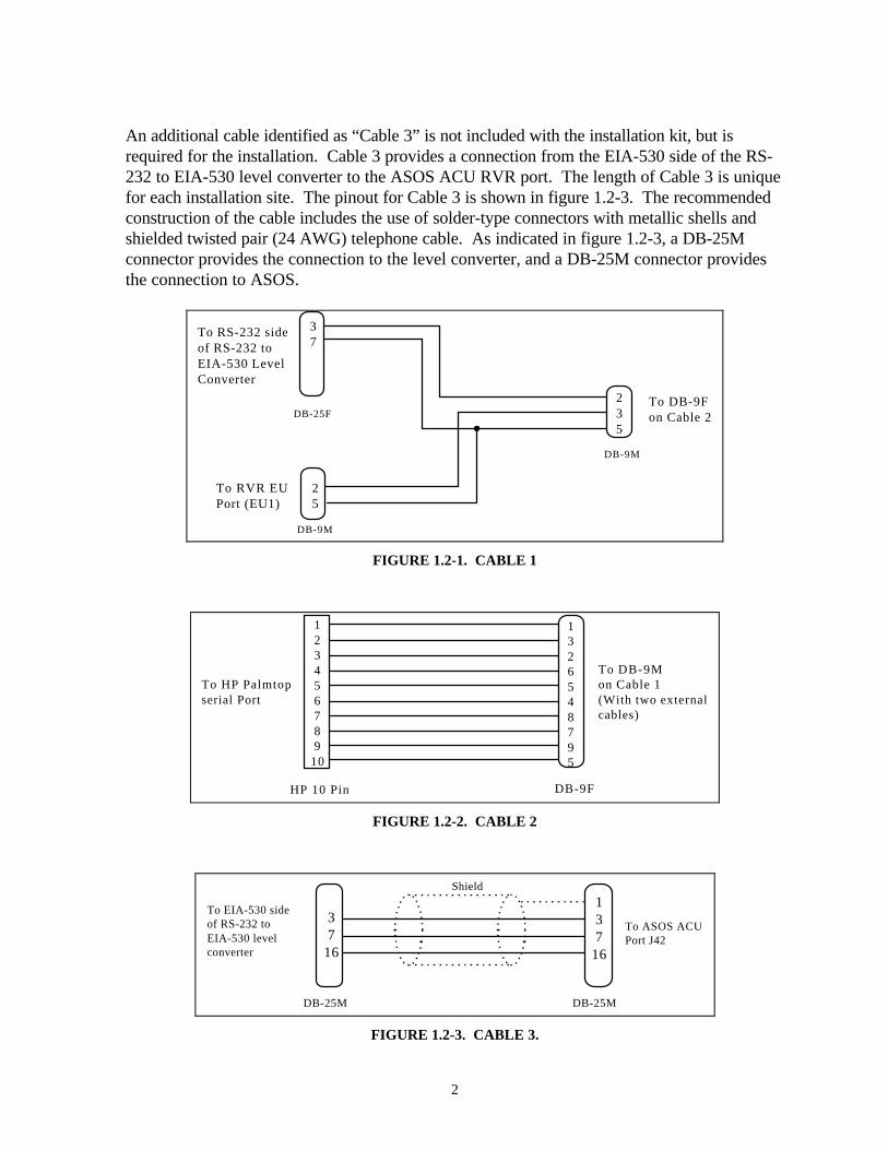
An additional cable identified as “Cable 3” is not included with the installation kit, but isrequired for the installation. Cable 3 provides a connection from the EIA-530 side of the RS-232 to EIA-530 level converter to the ASOS ACU RVR port. The length of Cable 3 is uniquefor each installation site. The pinout for Cable 3 is shown in figure 1.2-3. The recommendedconstruction of the cable includes the use of solder-type connectors with metallic shells andshielded twisted pair (24 AWG) telephone cable. As indicated in figure 1.2-3, a DB-25Mconnector provides the connection to the level converter, and a DB-25M connector providesthe connection to ASOS.
DB-9M
To DB-9Fon Cable 2
235
DB-9M
To RVR EUPort (EU1)
25
DB-25F
To RS-232 sideof RS-232 to EIA-530 LevelConverter
37
FIGURE 1.2-1. CABLE 1
DB-9F
To DB-9Mon Cable 1(With two externalcables)
1326548795
To HP Palmtopserial Port
123456789
10
HP 10 Pin
FIGURE 1.2-2. CABLE 2
DB-25M
To ASOS ACUPort J42
To EIA-530 sideof RS-232 toEIA-530 levelconverter
DB-25M
37
16
137
16
Shield
FIGURE 1.2-3. CABLE 3.

3
1.3 RS-232 to EIA-530 LEVEL CONVERTER.
An RS-232 to EIA-530 level converter adapts the RS-232 electrical signal from the HPPalmtop to EIA-530 levels compatible with the ASOS ACU RVR port. The converterrequires power from a polarized three-prong outlet rated at 120 volts alternating current(VAC). Figure 1.3-1 shows the required connections from the level converter to Cable 1 andCable 3.
RS-232 to EIA-530Level Converter
RS-
232
EIA
-530
Cable 1
DB
-25F
DB
-25M Cable 3
FIGURE 1.3- 1. CONNECTIONS TO/FROM SIGNAL LEVEL CONVERTER
2. INTERIM RVR/ASOS INTERFACE INSTALLATION.
This section details installation procedures for the Interim RVR/ASOS Interface. Personnelrequired for the installation include both Federal Aviation Administration (FAA) RVRtechnicians and National Weather Service (NWS) ASOS technicians. Contact the appropriateFAA/NWS personnel to plan the installation. The following steps should be followed forproper installation of the Interim RVR/ASOS Interface. Figure 2-1 shows a diagram of theoverall Interim RVR/ASOS Interface connectivity.
a. Verify all components on the enclosed packing slip were received.
b. Ensure that all powered Interim RVR/ASOS components are off.
c. Construct and install Cable 3 between the RVR and ASOS equipment cabinets.Refer to section 1.2 for cable pinouts and recommended cable materials. Verifycable continuity, but do not connect the cable ends to the HP Palmtop or ASOSduring this step.
d. Attach the DB-9M connector on Cable 1 (which contains one external cable) to theNew Generation RVR EU port (EU1). Secure this connection with connectorscrews.
e. Attach the DB-25F connector of Cable 1 to the RS-232 end of the RS-232 to EIA-530 level converter. The label on top of the level converter indicates the interfacefor each end. Secure this connection with connector screws.
f. Attach the other DB-9M connector on Cable 1 (which contains two externalcables) to the DB-9F connector on Cable 2. Secure connection with connectorscrews.

4
g. Attach the 10-pin HP custom connector to the HP Palmtop serial port. The serialport is keyed for proper insertion.
h. Attach the DB-25M connector on Cable 3 to the EIA-530 side of the levelconverter. Secure the connection with connector screws.
i. Attach the DB-25M connector on Cable 3 to the ASOS ACU port labeled “RVR”.The port is also labeled “J42”. Secure the connection with the connector screws.
j. Connect the Alternating Current (AC) adapter to the RS-232 to EIA-530 levelconverter and plug the AC adapter into a 120-VAC outlet inside the RVRequipment cabinet. If possible, secure both ends of the connection with cable ties.
NOTE: If power to the level converter is disabled or the power cable becomes dislodged,the level converter will not operate and data transmission to the ASOS will be disabled.
HP 200 LXPalmtop PC
RVRDPU
RS-232to
EIA-530Converter
ASOSACU
Cable 2
Cable 1
Cable 3
CO
M 1
10 P
in
DB
-9F
DB
-9M
DB
-9M
EU
1
DB-25F
DB-25M
RVR
DB-25M
FIGURE 2-1. INTERIM RVR/ASOS INTERFACE CONNECTIVITY

5
3. INITIALIZING THE INTERIM RVR/ASOS INTERFACE.
This section describes how to start operation of the Interim RVR/ASOS Interface. Asmentioned in section 1.1, RVR/ASOS software and supporting utilities have been loaded onthe HP Palmtop’s internal drive prior to shipping to your site. Your HP Palmtop should beready for initialization.
Prior to initialization, technicians/users will need to identify the RVR Visibility Sensor (VS)Sensor Interface Electronics (SIE) number and the runway designated for long-line RVRreporting (e.g., VS 03 and runway 36L). By definition, the long-line VS SIE shouldcorrespond to the touchdown location of the designated runway. For some locations, the NewGeneration RVR long-line VS will replace the remaining Tasker sensor as the long-linereporting VS.
Completion of the initialization process will require a verification of the transmitted data onASOS display screens. As a result, the participation of NWS technicians or Contract Weatherobservers is required. Contact the appropriate FAA/NWS personnel (section 5) to coordinatethis event.
3.1 RVR SYSTEM CONFIGURATION SETTINGS.
New Generation RVR system configuration modifications may be required to ensure properoperation of the Interim RVR/ASOS Interface. The following parameters should beset/verified from the RVR Maintenance Data Terminal (MDT) for operation with the InterimRVR/ASOS Interface.
From the “Configuration.Limits.Product” screen (refer to appendix F for a flowchart of RVRMDT screens), set/verify the following parameters:
a. ENGINEERING DATA OUTPUT INTERVAL: Set to “006” secondsb. OUTPUT FILTERED VS AND ALS VALUES (Y/N): Set to “Y”
If entry of new parameters is required, the user must execute the configuration change field toproperly initiate the modification.
Additionally, the long-line RVR VS should be configured on the MDT“Configuration.Runway-specification” and “Configuration.options” screens. Verify theseconfiguration settings from the aforementioned screens.

6
3.2 ASOS CONFIGURATION SETTINGS.
Proper configuration is also required at the ASOS to ensure data from the Interim RVR/ASOSInterface can be processed and reported as the long-line RVR. The configuration processincludes verifying that the proper software version is installed at ASOS as well as configuringthe ASOS RVR serial port. Officially fielded ASOS ACU software Version 2.45 or higher hasbeen qualified to support long-line RVR reporting. Consult your local NWS Technician orContract Weather Observer to ensure the ASOS is properly configured for long-line RVRreporting.
3.3 HARDWARE CONNECTIONS.
Before executing RVR/ASOS software, physical connections to each Interim RVR/ASOScomponent should be verified. This includes all cable connections (including power) to theRVR, HP Palmtop, level converter, and ASOS. If possible, all cable connections should besecured to prevent accidental disconnection. If not performed previously, a MDT should alsobe connected to the RVR DPU.
3.4 EXECUTING HP PALMTOP RVR-ASOS SOFTWARE.
[1] ACTION: Attach the HP Palmtop AC adapter to the HP Palmtop and plug into a 120-VAC outlet inside the RVR equipment rack. If possible, secure both ends of the connectionwith cable ties.
RESULT: HP Palmtop display should illuminate with text characters from the boot process oroperating system prompt. If this occurs, skip step [2] and proceed to step [3].
[2] ACTION: Turn on HP Palmtop by pressing the “ON” key located in the upper rightcorner.
RESULT: As long as the HP Palmtop has AC power and charged internal batteries, the liquidcrystal display (LCD) should illuminate with text characters from the boot process or operatingsystem prompt.
[3] ACTION: Reboot HP Palmtop hardware and software by simultaneously pressing the“CTRL”, “ALT”, and “DEL” keys.
RESULT: Immediate execution of the “autoexec.bat”, “config.sys”, and RVR/ASOS softwarefiles should occur. See appendix E for a listing of the autoexec.bat and config.sys files. Textcharacters from the boot process will scroll across the HP Palmtop display screen. Afterapproximately 10 seconds, the RVR/ASOS program will start. The program will display thecurrent configuration along with a message prompting the user to accept or change the currentsettings. The message and prompt are shown below:

7
*******CURRENT SETTINGS ARE SET AS:
ASOS RVR VS Sensor = VS 01Runway = 36L Com Port = COM1 Timer Interval = 30 secondsMaximum EDP message length = 2500 bytes
ACCEPT CURRENT DEFAULT SETTINGS? (Y/N)EXAMPLE. CURRENT SETTINGS MESSAGE
NOTE: The user has approximately 20 seconds to press the “N” key to change thecurrently stored settings. Otherwise, the program will continue to execute using thecurrently stored values for runway and VS.
[4] ACTION: Enter “N” if these settings do not match the long-line RVR VS and runwaynumber for your airport.
RESULT: Message will be displayed prompting user to enter the long-line VS number andthen runway identifier.
ENTER RUNWAY NUMBER (example : 22L):
ENTER VS NUMBER (1 to 18):EXAMPLE. VS AND RUNWAY MESSAGE PROMPT
Any valid one- or two-digit runway number (e.g., 1 to 36) and identifier (e.g., L, R, C, orblank) must be entered. Lower or uppercase letters can be used for the runway identifier. Ifthe runway identifier is a blank, press the “enter” key immediately after entry of the runwaynumber. Entry of invalid runway numbers and identifiers will not be accepted and will result inthe user being prompted to re-enter parameters.
[4a] Identify the VS number to be entered on the HP Palmtop for long-line reporting.Long-line VS number:___________
[4b] Via the RVR MDT, verify that the long-line VS entered in step 4a is the same VSnumber shown on the runway and touchdown location of the “Configuration.Runway-specification” MDT screen. If not, the VS number to be entered is incorrect or the RVR VShas not been properly configured.
NOTE: The label “Long-Line VS” will not appear on your MDT screen. Verify the VSnumber to be entered corresponds to the Touchdown VS on the runway designated forLong-Line RVR reporting.

8
[4c] If the VS number entered in step 4a has been verified in step 4b, proceed to step 5.Otherwise, determine the cause for the mismatch, correct, and repeat steps 4a, 4b, and 4c.
[5] ACTION: Enter runway identification and VS number, e.g., 27C, 12.
RESULT: RVR/ASOS software will continue to initialize. The entered runway identifier andVS number will be stored in the “info.dat” file. The initialization process ends after the HPPalmtop receives and acknowledges data frames from the RVR EU port. The example belowillustrates the messages that will appear on your HP Palmtop display. The messages will scrolloff the palmtop display in approximately 45 seconds.
EXAMPLE. RVR/ASOS SOFTWARE INITIALIZATION MESSAGES
Note that the numeric values for the “VS Sensor =”, “Runway =”, and “....byte_count =”, aresite specific and may be different for your RVR system configuration.
[6] ACTION: Verify the appearance of the ASOS ADU message on the HP Palmtop displayindicating that an ADU was transmitted to ASOS. Refer to the example ASOS ADU messageshown below.
<SOH>222616<STX>27C60+<ETX><BCC>EXAMPLE. ASOS ADU MESSAGE
Each ASOS ADU message displayed on the HP Palmtop should have the format shown in theexample. Definition of each field in the ADU message is shown below.
<SOH> Start of header Character222616 Active Product Processing Unit (PPU) time stamp<STX> Start Of Text Character27C60+ Runway Identifier and Long-line RVR Product<ETX> End Of Text Character<BCC> Block Check Code
ASOS RVR VS Sensor = VS 12Runway = 27C Com Port = COM1 Time Interval = 30 secondsMaximum EDP message length = 2500 bytes********************get_started(0) byte_count = -1675************************************get_started(1) byte_count = 929************************************get_started(0) byte_count = 963************************************get_started(1) byte_count = 963************************************get_started(2) byte_count = 963************************************NEW RLIM BYTE COUNT 963****************

9
As long as EU data frames are consistently received by the HP Palmtop without interruption orvariation in frame size, the RVR/ASOS software will create and transmit an ASOS ADU every30 seconds. Interruptions in EU data frames or changes in the size of EU data frames maycause the output interval of ASOS ADUs to momentarily change.
[7] ACTION: On the HP Palmtop, verify that the RVR/ASOS software is receiving RVR EUdata frames every 6 seconds (+ 2 seconds). Note the difference in time stamp for eachmessage displayed.
RESULT: Messages acknowledging that the RVR/ASOS software is receiving RVR EU dataframes should appear on the HP Palmtop display approximately every 6 seconds, as shown inthe example below.
Note: 6-second difference01/26/97 23:04:53LAST GOOD MESSAGE WAS AT: 01/26/97 10:09:41
01/26/97 23:04:59LAST GOOD MESSAGE WAS AT: 01/26/97 10:09:41
01/26/97 23:05:05LAST GOOD MESSAGE WAS AT:01/26/97 10:09:41
EXAMPLE. RVR EU DATA FRAME ACKNOWLEDGMENT MESSAGE
[8] ACTION: Verify the transmitted ASOS ADUs appear on the ASOS “12 HR ARCHIVE”,“1-MINUTE CURRENT SENSOR DATA” and “1-MINUTE” display screens.
RESULT: RVR products appearing on ASOS display screens should match RVR valuescontained within the recently transmitted ADU. Refer to the example below.

10
HP PALMTOP DISPLAY SCREEN:
ASOS Message: <SOH>222616<STX>27C60+<ETX><BCC>
ASOS 12 HR ARCHIVE SCREEN: RVR product match
16:15:04 01/26/97 2215Z MEMPHIS INTERNATIONAL ARPTUTC VIS1 D/N1 VIS3 D/N3 WIND DIR/SPD 5SEC WIND RVR2149 .050 D .050 D 186 11 187 13 27C60+2150 .050 D .052 D 186 12 181 14 27C60+
12 HR ARCHIVE
ASOS CURRENT SENSOR DATA SCREEN: RVR product match
16:15:04 01/26/97 2215Z MEMPHIS INTERNATIONAL ARPTUTC VIS1 D/N1 VIS3 D/N3 TEMP DEWPT 5SEC WIND RVR2149 .050 D .050 D 60 59 187 13 27C60+2150 .050 D .052 D 60 59 181 14 27C60+
RAW SENSOR DATA
ASOS 1-MINUTE SCREEN: RVR product from HP PALMTOP ASOS ADU
SKY = CLR BLO 120
VISIBILITY = 5 TEMP/DEWPT = 15.6/15.0 C 60/59 FRVR = R27C/60+ WIND DIR/SPD = 130/11PRESENT WX= -RA BR ALTIMETER = 29.99
REMARKS = RMK AO2 P0001 TSNO
TESTM KMEM 041356Z AUTO 13010KT 4SM -RA BR SCTO35 BKNO48 OVC095 16/14A2999 RMK A02 RAB1258 SLP155 P0001 T01560144 TSNO
[9] ACTION: Place and secure the HP Palmtop on a shelf inside New Generation RVRequipment cabinet.
Completion of all of the aforementioned steps concludes the initialization process.

11
4. INTERIM RVR/ASOS SHUTDOWN PROCEDURES.
To gracefully shutdown operation of RVR/ASOS software, press the “Q” key. This will stopexecution of the RVR/ASOS software and return the HP Palmtop to the DOS environment.Access to the PCMCIA memory card or built-in applications on the internal drive is nowpossible via DOS commands. At this point, although the RVR/ASOS program has beendisabled, the watch-dog timer is still active.
The watch-dog timer is designed to detect when the RVR/ASOS program is not operating andautomatically reboot the HP Palmtop hardware and RVR/ASOS software. This feature isintended to reduce maintenance actions such as restarting the HP Palmtop in the event theRVR/ASOS software stops operating. The HP Palmtop is configured to produce a briefaudible alarm when the watch-dog timer detects a 1-minute period of keyboard or displayinactivity. This will result in a reboot being scheduled. Refer to appendix B, section B.4 foradditional specifics concerning the watch-dog timer.
If need arises to turn off the HP Palmtop display, disconnect the Palmtop’s AC adapter fromthe outlet and press the “ON” key. This should result in the removal of backlighting andcharacters/graphics observed on the display. Turning off the HP Palmtop display also disablesoperation of the watch-dog timer. Pressing the “ON” key again will initialize the display at thepoint where it was turned off; e.g., DOS prompt, application, etc. A hardware/software restartwill not occur.

12
5. TECHNICAL SUPPORT.
If additional technical support is required to resolve problems with the installation or operationof your Interim RVR/ASOS Interface, please contact one of the offices listed below.
Mike Monroney Aeronautical CenterField Support Engineering, AOS-240Oklahoma City, OK 73125POC: Jerry OuillettePhone: (405) 954-5163
FAA William J. Hughes Technical CenterWeather Branch, ACT-320Atlantic City International AirportAtlantic City, NJ 08405POC: Mike McKinneyPhone: (609) 485-5516
Federal Aviation Administration HeadquartersNavigation and Landing Product Team, AND-520RVR Program OfficeWashington, DC 20590POC: Deborah LucasPhone: (202) 358-5112
5.1 MAINTENANCE COORDINATION PERSONNEL.
Contact personnel from the list below to report and resolve Interim RVR/ASOS Interfacemaintenance issues:
ASOS Operations and Monitoring Center (AOMC) 800-242-8194
FAA NAV/COM SUPERVISOR * FAA NAV/COM SUPERVISOR
* Refer to your local airport directory for the FAA NAV/COM Supervisor’s telephonenumber.
13
6. ACRONYMS.
AC Alternating CurrentACU Acquisition Control UnitALS Ambient Light SensorADU Application Data UnitAOMC ASOS Operations Monitoring CenterASOS Automated Surface Observing SystemAWG American Wire GaugeBCC Block Check CodeCDCWO
Controller DisplayContract Weather Observer
DOS Disk Operating SystemDCE Data Communication EquipmentDTE Data Terminal EquipmentDPU Data Processing UnitEIA Electronics Industries AssociationEU External UserETX End of TextFAA Federal Aviation Administration
HP Hewlett PackardHR HourID Identification
LCD Liquid Crystal DisplayMDT Maintenance Data TerminalNWS National Weather ServiceOT&E Operational Test and EvaluationPOC Point of ContactPC Personal ComputerPPU Product Processing Unit
RAM Random Access MemoryRLIM Runway Light Intensity MonitorRS Required StandardRVR Runway Visual RangeSOH Start Of HeaderSIE Sensor Interface ElectronicsSTX Start of Text
VACVS
volts alternating currentVisibility Sensor

APPENDIX ARVR AND INTERIM RVR/ASOS INTERFACE MAINTENANCE ACTIONS

A-1
A. RVR & INTERIM RVR/ASOS INTERFACE MAINTENANCE ACTIONS.
This section discusses maintenance actions or modifications to the New Generation RVR andrespective coordination efforts between the FAA and NWS. By prior agreement between theFAA and NWS, all RVR maintenance/modifications which will affect long-line RVR datashould be coordinated with the ASOS Operations and Monitoring Center (AOMC). In general,any action that could affect the RVR EU output frame size or long-line RVR data should becoordinated through the AOMC. The following sections provide procedures which should befollowed for specific RVR system actions.
A-1 LONG-LINE RVR VS MAINTENANCE OR CALIBRATION.
When performing maintenance or calibration on the long-line RVR VS, precautionarymeasures must be taken to ensure that incorrect long-line RVR products are not sent toASOS. Procedural steps for conducting maintenance and calibration of the long-line RVRVS sensor are addressed below.
Maintenance/Calibration Procedure:
1. Notify the Contract Weather Observer (CWO) or AOMC that maintenance will beperformed on the long-line RVR VS.
2. Via the MDT Product editing screen, manually fail the long-line RVR product. Referto TI 6560.17, dated August 1, 1995, section 6.8.9 for details on manually failingRVR products.
3. Perform maintenance/calibration actions on the RVR VS in accordance with TI6560.17.
4. Via the MDT Product editing screen, manually unfail the long-line RVR product.Refer to TI 6560.17, dated August 1, 1995, section 6.8.9c for details on unfailingRVR products.
5. Verify that the HP Palmtop is generating ASOS ADUs with numeric RVR values.6. Verify that ASOS is receiving ADUs from the HP Palmtop by reviewing the ASOS
“12 Hour Archive” screen.7. Verify that the RVR values shown in the ASOS “12 Hour Archive” screen match the
RVR values generated by the HP Palmtop.8. Notify the CWO or AOMC that maintenance is completed on the long-line RVR VS.

A-2
A-2 AMBIENT LIGHT SENSOR (ALS) MAINTENANCE OR CALIBRATION.
When performing maintenance or calibration on the RVR ALS, the following procedureshould be followed.
Maintenance/Calibration Procedure:
1. Notify the CWO or AOMC that maintenance/calibration will be performed on theRVR ALS.
2. Via the MDT Product editing screen, manually fail the long-line RVR product. Referto TI 6560.17, dated August 1, 1995, section 6.8.9c for details on manually failingRVR products.
3. Perform maintenance/calibration actions on the RVR ALS in accordance with TI6560.17.
4. Via the MDT Product editing screen, manually unfail the long-line RVR product.Refer to TI 6560.17, dated August 1, 1995, section 6.8.9c for details on unfailingRVR products.
5. Verify the HP Palmtop is generating ASOS ADUs with numeric RVR values.6. Verify the ASOS is receiving ADUs from the HP Palmtop by reviewing the ASOS “12
Hour Archive” screen.7. Verify the RVR values shown in the ASOS “12 Hour Archive” screen match the RVR
values generated by the HP Palmtop.8. Notify the CWO or AOMC that maintenance is completed on the long-line RVR VS.
A-3 RESOLVING SYSTEM OR COMPONENT FAILURE.
When troubleshooting a system or component failure, the following procedure should befollowed.
System Troubleshooting Procedure:
1. Notify the CWO or AOMC that troubleshooting/maintenance will be performed on theRVR system and that RVR long-line data will not be available.
2. Disconnect Cable 2 from the HP Palmtop.3. Perform troubleshooting/maintenance actions on the RVR system in accordance with
TI 6560.17.4. When the system or component failure has been corrected, reconnect cable 2 to the
HP Palmtop serial port.5. Verify the HP Palmtop is generating ASOS ADUs with numeric RVR values.6. Verify the ASOS is receiving ADUs from the HP Palmtop by reviewing the ASOS “12
Hour Archive” screen.7. Verify the RVR values shown in the ASOS “12 Hour Archive” screen match RVR
values generated by the HP Palmtop.8. Notify the CWO or AOMC that maintenance is completed on the long-line RVR VS.

A-3
A-4 PERFORMING RVR SYSTEM OR COMPONENT RESET.
When performing RVR system or component resets, the following procedure should befollowed.
RVR Reset Procedure:
1. Notify the CWO or AOMC that maintenance will be performed on the RVR system.2. Via the MDT Product editing screen, manually fail the long-line RVR product. Refer
to TI 6560.17, dated August 1, 1995, section 6.8.9c for details on manually failingRVR products.
3. Perform RVR system or component reset actions in accordance with TI 6560.17.4. Via the MDT Product editing screen, manually unfail the long-line RVR product.
Refer to TI 6560.17, dated August 1, 1995, section 6.8.9c for details on unfailingRVR products.
5. Verify that the HP Palmtop is generating ASOS ADUs with numeric RVR values.6. Verify that ASOS is receiving ADUs from the HP Palmtop by reviewing the ASOS
“12 Hour Archive” screen.7. Verify that the RVR values shown in the ASOS “12 Hour Archive” screen match the
RVR values generated by the HP Palmtop.8. Notify the CWO or AOMC that maintenance is completed on the long-line RVR VS.

APPENDIX BHP PALMTOP ON-SCREEN MESSAGES

B-1
B. HP PALMTOP ON-SCREEN MESSAGES.
This section provides examples of HP Palmtop on-screen messages that could occurduring operation of the Interim RVR/ASOS Interface. On-screen messages discussed inearlier sections of this guide are not repeated.
B-1 EU DATA FRAME.
The EU data frame which appears on the HP Palmtop display as an ASOS ADU is beingtransmitted is illustrated as Message B-1. The message displays the following information:
a. New Generation RVR date and time stamp,b. VS and ALS sensor data from the most recent EU data frame,c. Extinction coefficient (sig) and ambient light (al) values used to calculate the
long-line RVR,d. Calculated raw data long-line RVR (rv), ande. ASOS ADU message sent to ASOS.
01/27/00 02:02:23 22:30VS 01 2.62 11 10VS 02 1.70 4 12VS 03 3.25 9 3VS 04 2.22 10 8ALS 2.0 6sig=2.620000 al=2.000000 rv=7199.891113ASOS Message: <SOH>020223<STX>27C60+<ETX><BCC>MESSAGE B-1. EU DATA FRAME
The New Generation RVR date and time stamp are shown on the first line of the message,followed by the configured VS and ALS sensors. Numerical entries to the right of the VSidentifier indicate the extinction coefficient measurement and window contaminationreadings for the transmitter and receiver, respectively. Numerical entries to the right ofthe ALS indicate the ambient light measurement and window contamination reading.These readings should match readings contained on the applicable MDT screens.
The line in the message containing the “sig”, “al”, and “rv” values identify the extinctioncoefficient of the long-line VS (sig), the ALS measurement (al), and the raw calculatedlong-line RVR product (rv). Note that the “sig” value matches the long-line extinctioncoefficient and the “al” value matches the ALS value in the message. Note also that theraw “rv” calculation is rounded appropriately in the ASOS message from 7199.891113feet to 60+.
This message should be displayed every 30 seconds on the HP Palmtop’s display.

B-2
B-2 VS NOT FOUND.
If the VS ID identified as the long-line RVR VS does not appear in the EU output data, a“message indicating the VS was not found will be displayed. A sample “VS NOTFOUND” message is shown in Message B-2:
************* VS 05 NOT FOUND **************MESSAGE B-2. HP PALMTOP VS NOT FOUND MESSAGE
In this scenario, ASOS ADUs are not transmitted to ASOS until the long-line VS isdetected in the EU output data.
B-3 CORRUPTED DATA INDICATION.
The RVR/ASOS software operating on the HP Palmtop uses the Runway Light IntensityMonitor (RLIM) field to determine the end of the EU data frame. If the RLIM field orother fields within the EU data frame become corrupted or are not recognized by theRVR/ASOS software, no data will be transmitted to ASOS and an error message will bedisplayed on the HP Palmtop display. The error message, such as the message shown inMessage B-3, will be preceded by a screen dump of the data received by the RVR/ASOSsoftware.
*******************************************************************************************ERROR: PACKET NOT RECEIVED IN PAST 500 SECONDS*******************1000 BYTES HAVE BEEN READ************************************************************************
MESSAGE B-3. EU DATA NOT RECOGNIZED
If the RVR/ASOS software detects a transient change in the EU data frame, a messagesuch as the one shown in Message B-4 will be displayed on the HP Palmtop.
BAD DATA RECEIVED ---100 bytes LAST GOOD MESSAGE WAS AT 15:44MESSAGE B-4. BAD DATA RECEIVED

B-3
If the EU data frame changes to a new size which is consistent, the RVR/ASOS softwarewill restart the EU data frame acknowledgment process. An example of theacknowledgment process is shown in Message B-5:
********************get_started(0) byte_count = -1675************************************get_started(1) byte_count = 929************************************get_started(0) byte_count = 963************************************get_started(1) byte_count = 963************************************get_started(2) byte_count = 963************************************NEW RLIM BYTE COUNT 963****************
MESSAGE B-5. EU DATA FRAME SIZE ACKNOWLEDGMENT
B-4 RVR/ASOS SOFTWARE NOT OPERATING.
Since the Interim RVR/ASOS Interface is automated and unmanned, a watch-dog timerhas been incorporated into the HP Palmtop configuration. The watch-dog timer’s purposeis to detect if/when the RVR/ASOS software is not operating, and its function is to rebootthe HP Palmtop when display screen or keyboard inactivity exceeds 1 minute. When thedisplay screen or keyboard inactivity exceeds 1 minute, the message shown in Message B-6 will be displayed on the screen. If the countdown period for the scheduled rebootexpires prior to keyboard activity, the HP Palmtop will automatically reboot and theRVR/ASOS software will be restarted. The RVR/ASOS software will initialize using thelast entered RVR VS and runway identification. Watch-dog timer initiated reboot datesand times are stored in a log file entitled “reboot.log”. See section D.3, SpecialInstructions for specifics concerning the watch-dog timer log file.
Inactivity time-out exceededReboot in 60.00 seconds if no key pressed
Press any key to cancel reboot
MESSAGE B-6. REBOOT PENDING

APPENDIX CTROUBLESHOOTING

C-1
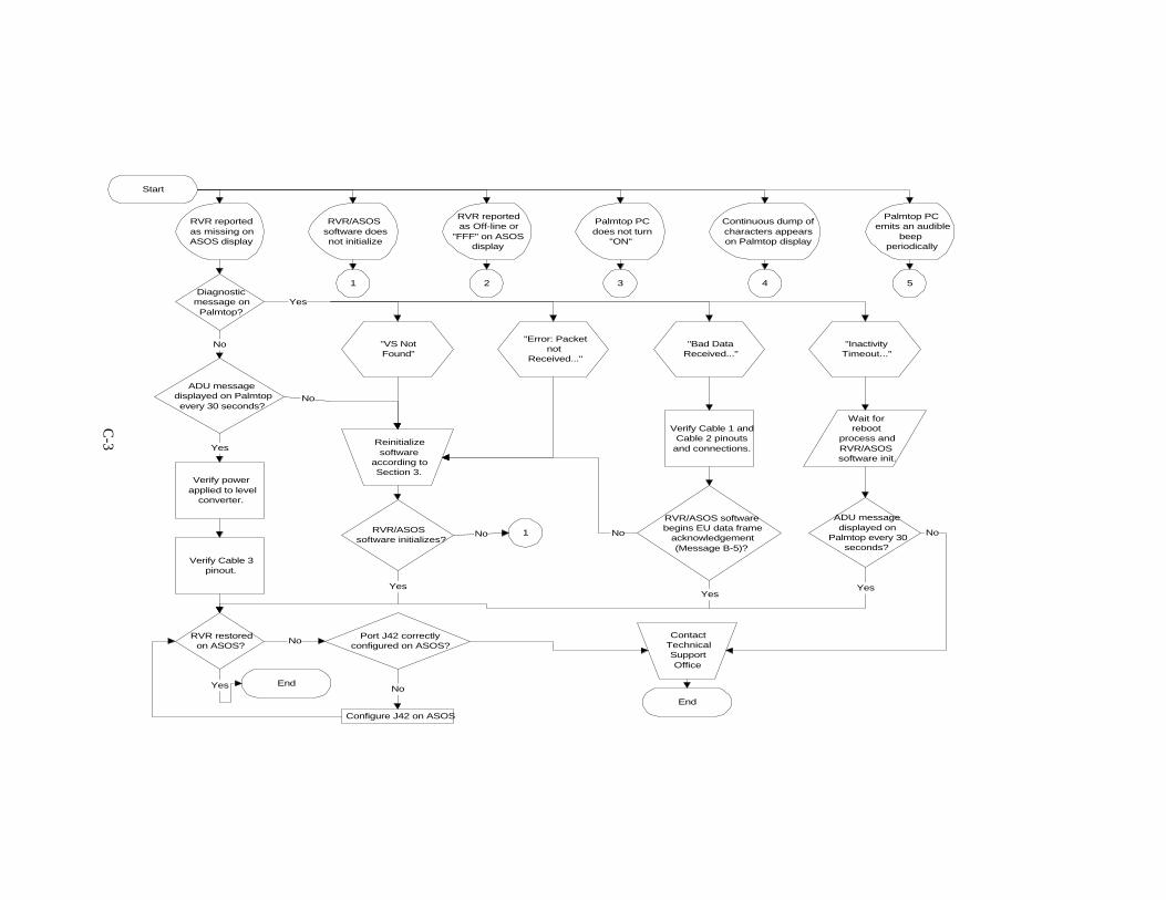
C. TROUBLESHOOTING.
This appendix provides information in troubleshooting problems associated with the HPPalmtop and resident RVR/ASOS software. A set of troubleshooting flowcharts has beendeveloped to provide assistance. When using the flow chart, begin at the “start” indicatorand proceed to the box indicating the particular problem. Follow the flowchart to “end”,executing the actions described along the way. In the event the system problem is notindicated on the flowchart, contact a Technical Support Office listed in section 5.
Sections C-1 and C-2 and figure C-1 are expanded instructions referenced within thetroubleshooting flowcharts.
Note: Prior to performing troubleshooting activities on the Interim RVR/ASOSInterface, notify the AOMC that maintenance will be performed on the RVRsystem.
08:52:37 04/04/97 MEMPHIS INTERNATIONAL AIRPORT
PORT MOD FUNCTION PORT MOD FUNCTION PORT MOD FUNCTION1-1 4-1 UPS 2 2 PRESSURE 3 RVR 3 7 VDU-1 4 4 6 PRINTER2-1 ACU-DCP A 2 PRESSURE #1 3 OID-4 USER 1 4 VOICE3-1 ACU-DCP B 2 PRESSURE #2 3 5 OID-5 USER 2 4 OID-1 USER
FUNCTION RVRSTATUS ENABLED HANDSHAKE NONE ACU SERIAL COMMSBAUD RATE 2400 CONNECTION HARD-WIREPARITY SELECT EVENBITS/CHAR 7STOP BITS 1
FIGURE C-1. ASOS PORT MOD FUNCTION SCREEN

C-2
C-1. COPYING FILES FROM THE PCMCIA CARD.
An “autoexec.bat” and/or “config.sys” file can be copied from the PCMCIA memory cardsupplied with your Interim RVR/ASOS Interface Installation Kit. Follow the followingprocedure to copy a file from the PCMCIA memory card onto the HP Palmtop’s “c:\”drive.
1. From the “c:\” dos prompt, remove power from the HP Palmtop by pressing the “ON”key.
2. Insert the PCMCIA memory card by holding the card, logo facing up, and sliding itinto the slot on the left side of the HP Palmtop. The card is properly inserted when theinserted card edge is flush with the HP Palmtop’s case.
3. Turn the HP Palmtop on by pressing the “ON” key.4. If not at the “c:\” drive, type “c:\” at the dos prompt to go to the “c:\” drive.5. At the “c:\” dos prompt, type “copy a:\filename.fil c:\”. Insert the proper filename in
place of filename.fil.6. Verify the file was copied through acknowledgment of the file transfer confirmation
message “1 file(s) copied” displayed on the HP Palmtop.7. Repeat steps 5 and 6 for each file which needs copied.8. Turn the HP Palmtop off by pressing the “ON” key.9. Remove the PCMCIA memory card by sliding the card eject switch to the left.10. Turn the HP Palmtop on by pressing the “ON” key.
C-2. TROUBLESHOOTING FLOWCHART.
The following pages provide a flowchart that can be used for isolating and trouble-shooting problems occurring on the Interim RVR/ASOS Interface, the ASOS or the NewGeneration RVR.
Start
RVR reportedas missing onASOS display
Diagnosticmessage onPalmtop?
ADU messagedisplayed on Palmtopevery 30 seconds?
Verify powerapplied to level
converter.
Verify Cable 3pinout.
RVR restoredon ASOS?
End
RVR/ASOSsoftware doesnot initialize
RVR reportedas Off-line or
"FFF" on ASOSdisplay
Palmtop PCdoes not turn
"ON"
Continuous dump ofcharacters appearson Palmtop display
Palmtop PCemits an audible
beepperiodically
No
Yes
Yes
"VS NotFound"
"Error: Packetnot
Received..."
"Bad DataReceived..."
"InactivityTimeout..."
Yes
Reinitializesoftware
according toSection 3.
No
RVR/ASOSsoftware initializes?
Yes
1No
Verify Cable 1 andCable 2 pinouts
and connections.
RVR/ASOS softwarebegins EU data frame
acknowledgement(Message B-5)?
Wait forreboot
process andRVR/ASOSsoftware init.
ADU messagedisplayed on
Palmtop every 30seconds?
No
YesYes
ContactTechnicalSupportOffice
No
Port J42 correctlyconfigured on ASOS?
No
Configure J42 on ASOS
No
End
1 2 3 4 5
C-3

2
Is Long LineRVR "FFF" on
CD?
Is MDT logged-onLong Line VS or
ALS SIE?
Performmaintenance onRVR system inaccordance with
App. A
Is RVR restoredon ASOS?
ContactTechnicalSupport
End
Logout of SIE
No
Yes
No
Yes
Yes
No
5
Does battery lowmessage appear on
Palmtop display?
Does inactivitymessage appear on
Palmtop display?
Allow Palmtop PCand RVR/ASOS
software toautomatically
reinitialize
Initializationsucceeded?
RVR restoredon ASOS?
No
Yes 3
No
Yes
No
Yes
No
Yes
C-4

3
Is Palmtop's ACadapter connectedto AC power and
Palmtop?
Replace Palmtop'sbackup battery (Refer to
App. B of HP 200LXUser's Guide)
Replace Palmtop's mainbatteries (Refer to App.B of HP 200LX User's
Guide)
Palmtop turns"On"?
Setup Palmtop PCto recharge mainbatteries (Refer toApp. B of HP 200LX User's Guide)
Connect Palmtop'sAC adapter to AC
power and thePalmtop
Reinitialize RVR/ASOS software
according toSection 3
Softwareinitializedproperly?
End
Yes
Yes
ContactTechnicalSupport
No
No
4
Yes1
No
1
Verify contents ofPalmtop "autoexec.bat"and "config.sys" files
with contents shown inApp. E (Refer to HP200LX User's Guide)
File contentscorrect?
Copy new "autoexec.bat"and "config.sys" filesfrom PCMCIA card to"c:\" drive on Palmtop(Refer to Section C-1)
NoUsing the DOS
command "dir", verifyRVR/ASOS software is
loaded on "c:\" drive(Refer to App. E for drive
contents)
Software loadedcorrectly?
Yes
Yes
Copy RVR/ASOSsoftware and utilityfiles from PCMCIAcard to "c:\" drive
(Refer to Section C-2)
No
C-5

APPENDIX DSPECIAL INSTRUCTIONS

D-1
D. SPECIAL INSTRUCTIONS.
This section briefly describes precautions that should be taken to prevent otherwiseunnecessary maintenance actions on the HP Palmtop and RVR/ASOS software.
NOTE: Loss of all data on the HP Palmtop internal disk and/or memory card couldresult if these precautions are not followed.
D-1 HP PALMTOP BATTERIES.
Your HP 200LX Palmtop computer has been equipped with two size “AA” Nickel-Cadmium rechargeable main batteries and a lithium coin cell battery for backup. Thebackup battery prevents data loss when the main batteries are dead or out of the system.The backup battery should be replaced once a year. When changing batteries, pleasefollow the instructions given below.
1. Halt operation of the RVR/ASOS program and turn off HP Palmtop display asdescribed in section 4.
2. If inserted, remove the PCMCIA memory card by sliding the card eject switch to theleft.
3. Replace batteries in accordance with appendix B of the HP 200LX User’s Guide.4. After batteries have been installed, turn on the HP Palmtop by plugging in the AC
adapter and pressing the “ON” key.5. Enter the HP Palmtop’s setup utility and verify that the HP Palmtop is configured for
Nickel-Cadmium batteries and that recharging is selected (follow the instructions inappendix B of the HP 200LX User’s Guide).
6. Reinitialize RVR/ASOS software as defined in section 3.
D-2 PCMCIA MEMORY CARD.
Never insert or eject the PCMCIA memory card while the HP Palmtop is on. Loss of dataon the memory card could result. Additionally, ensure that the DOS prompt is not set ondrive “a:\” when ejecting the PCMCIA card. Enter “c:”, “d:”, or “e:” on the HP Palmtopto change the DOS drive, turn the power off, and then eject the card.
D-3 WATCH-DOG TIMER REBOOT.
A log file resident on the PCMCIA card and HP Palmtop internal drive can be used todetermine if restarts of the RVR/ASOS software have occurred during periods when auser has not examined the HP Palmtop display. This log file is entitled “reboot.log” and islocated on the internal drive “c:\” and the PCMCIA card drive “a:\”. The reboot.log filerecords the date and time of reboots initiated by the watch-dog timer. Follow theprocedure below to view the “reboot.log” file.

D-2
1. Notify the AOMC that the Interim RVR/ASOS Interface will be out of service.2. Exit the RVR/ASOS software in accordance with section 4.3. From the “c:\” dos prompt, type “type reboot.log”. A sample listing of the reboot.log
file is shown below.
Feb 24 10:09:41 1997 Date and time of reboot
Feb 24 11:10:25 1997Sample Listing of “Reboot.log” File

APPENDIX E
INTERNAL DRIVE/PCMCIA MEMORY CARD DIRECTORY TREES ANDFILE CONTENTS

E-1
E. INTERNAL DRIVE/PCMCIA MEMORY CARD DIRECTORY TREES AND FILECONTENTS
AUTOEXEC.BAT CONTENTS@echo offRem To customize DOS startup files, copy config.sys andRem autoexec.bat from the D drive to the C drive andRem edit the C drive versions to meet your needs.RemRemRem Set prompt, path, and select C drive.Remprompt $p$gpath c:\;d:\;d:\bin;d:\dosc:
RemRem Following assign enables referencing the plug-in card asRem drive E (in addition to A). Using E allows some programsRem to run which refuse to run from a drive that is normallyRem associated with a floppy drive.Remassign e:=a:
@echo onRemRem Load the Card Installation Client TSR to provide supportRem for PCMCIA modem cards. If these cards will not be used,Rem prefacing with Rem will save system RAM.Remd:\bin\cic100\gen 1
RemRem Load the first LapLink Remote Access TSR as required by theRem Server application. If the Server will not be used,Rem prefacing with Rem will save system RAM.Remcall d:\bin\llras
Rem Following 200 command starts the System Manager whichRem provides access to the built-in applications.RemREM 200RemRem Need to power up and activate COM 1 port

E-2
AUTOEXEC.BAT CONTENTS (continued)
serctl /w
Rem Need to set COM 1 portmode com1: 2400, n, 8, 1Remc:REM start watchdog timerdeadman /A1Rem Need to run software to get datarvr_asos
CONFIG.SYS CONTENTSfiles = 20buffers = 20device = c:\stacker\stacker.com
INFO.DAT CONTENTSVS_01 22R com1 2500 30
FILES & DIRECTORIES REQUIRED ON PCMCIA MEMORY CARD [A:\]FILE NAME SIZE (BYTES)a:\stacker ----a:\1info.dat 21a:\wear.exe 3,519a:\1deadman.exe 17,788a:\1rvr_asos.exe 38,732a:\1autoexec.bat 1,305a:\config.sdp 35a:\1config.sys 80a:\2stacker.exe TBDa:\2stacker.ins TBDa:\reboot.log ----a:\asossave.exe 33,054
FILES & DIRECTORIES REQUIRED ON INTERNAL DRIVE [C:\]FILE NAME SIZE (BYTES)c:\info.dat 21c:\deadman.exe 17,788c:\rvr_asos.exe 38,732c:\autoexec.bat 1,305c:\config.sys 80 1 These files will not be viewable on drive a:\ if the stacker program is not operating.2 These files will not be viewable on drive a:\ if the stacker program is operating.

E-3
c:\stacker ----c:\stacker\stacker.com 43,727c:\stacker\sinstall.exe 14,112c:\check.exe 41,945c:\sdir.exe 35,689c:\config.sdp 80c:\wear.exe 3519c:\asossave.exe 33,054
FILES & DIRECTORIES REQUIRED ON INTERNAL DRIVE [D:\]FILE NAME SIZE (BYTES)d:\_DAT ----d:\_SYS ----d:\BIN ----d:\DOS ----d:\config.sys 80d:\123.dyn ----d:\123.set ----d:\123vs.ri ----d:\autoexec.bat 1266
FILES & DIRECTORIES REQUIRED ON INTERNAL DRIVE [E:\]FILE NAME SIZE (BYTES)e:\stacker ----e:\1info.dat 21e:\wear.exe TBDe:\1deadman.exe TBDe:\1rvr_asos.exe 38,732e:\1autoexec.bat 1266e:\config.sdp 80e:\1config.sys 80e:\2stacker.exe 14,112e:\2sinstall.exe 14,112e:\reboot.log ----e:\asossave.exe 33,054
1 These files will not be viewable on drive a:\ if the stacker program is not operating.2 These files will not be viewable on drive a:\ if the stacker program is operating.

APPENDIX F
NEW GENERATION RVR MDT SCREEN FLOWCHART

F-1
F. NEW GENERATION RVR MDT SCREEN FLOWCHART.H = HelpD = Data
P = Product Data displayS = Sensor Data Display
S = Single sensor displayT = sensor data by Type displayR = sensor data by Runway displayA = All sensor data display
S = StatusC = Configuration
O = OptionsR = Runway-specificationL = Limits
P = Product LimitsS = Sensor Limits
P = SIE ParametersS = Site ConstraintsD = Date/timeU = User ids, passwords
O = Owner password onlyM = Manager (all uic’s)
A = ArchiveO = 1-minute product archive dataF = 5-minute product archive dataH = one hour product archive dataR = Raw sensor archive dataA = Incident_1 archive dataB = Incident_2 archive data
T = Terminal-messageR = Rmm-monitorF = Fault-diagnosticsE = product-Editing
O = Override failure of an SIEM = Manual entry of ALS or RLIM data to be used in product calculationsF = Force failure of an RVR product
P = ParametersL = Limits display of MPU Maintenance ParameterV = Values display of MPU Maintenance Parameter
O = cOntrolV = software-VersionsL = Logout