the international implementation planamma-international.org/meetings/workshops/biarritz/... · amma...
TRANSCRIPT

African Monsoon Multidisciplinary Analysis Afrikaanse Moesson Multidisciplinaire Analyse Afrikanske Monsun : MultidisiplinFre Analyser
Analisi Multidisciplinare per il Monsone Africano Analisis Multidiciplinar de los Monzones Africanos Afrikanischer Monsun : Multidisziplinäre Analysen Analyse Multidisciplinaire de la Mousson Africaine
The International Implementation Plan
Preliminary version
September 2005

Coordinated by The International Coordination and Implementation Group (ICIG) Co-chairs: Thierry Lebel
Doug Parker With contributions from the Task Team leaders: Page TT1: Andreas Fink, Serge Janicot, Doug Parker 1 TT2a: Colin Lloyd, Chris Taylor 34 TT2b: Béatrice Marticorena, Francesco Cairo 46 TT3: Eric Mougin, Josiane Seghieri, Lassine Diarra 63 TT4: Luc Descroix, Bernard Cappelaere 87 TT5: Christophe Peugeot, Sylvie Galle 115 TT6: Bernard Bourles, Robert L. Moulinari, Peter Brandt 139 TT7: Jim Haywood, Jacques Pelon 149 TT8: Cyrille Flamant, Doug Parker 177 TT9: document not available And all the Task Team members Please find further information under www.amma-international.org Thierry Lebel Doug Parker Représentation IRD au Niger Institute for Atmospheric Science, BP 11416 Environment, School of Earth and Environment Niamey University of Leeds, Leeds, LS2 9JT, UK Niger Tel : +227 75 26 10; 75 31 15; 75 38 27 Tel. +44 (0)113 343-6739 Fax : +227 75 28 04 Fax +44 (0)113 343-6716 Email: [email protected] Email: [email protected]
AMMA Task Team 1 (ARG). A. Fink/S. Janicot/D. Parker 07.09.2005
TT1: Working group on conventional upper-air, UHF/VHF profiler
and GPS observations
(prepared by: Andreas Fink, Serge Janicot and Doug Parker)
Reference document (07 September 2005) 1. Scientific justification and objectives: ............................................................................... 1 2. Observing strategy ............................................................................................................. 2
2.1. Overall strategy ........................................................................................................... 2 2.1.1. Funding issues (radiosondes) ............................................................................... 4 2.1.2. Communication and infrastructure improvement needs (radiosondes)................ 6 2.1.3. GPS Total Columnar Water Vapour (TCWV) Measurements............................. 6 2.1.4. UHF/VHF profiler measurements ........................................................................ 7 2.1.5. PILOT strategy..................................................................................................... 8
2.2. List of sites, instruments and relevant maps................................................................ 8 2.3. Priorities (Radiosondes) ............................................................................................ 10
3. Deployment ...................................................................................................................... 11 3.1. Planning ..................................................................................................................... 11 3.2. Logistical considerations ........................................................................................... 11
4. Partnership........................................................................................................................ 11 4.1. Training program....................................................................................................... 11
5. Organisation of the TT. .................................................................................................... 12 5.1. Leaders, core group, membership.............................................................................. 12 5.2. Internal coordination ................................................................................................. 13 5.3. External diffusion of the information and reporting.................................................. 13 5.4. Coordination with other TTs ..................................................................................... 13
6. ANNEX 1...................................................................................................................... 14 7. ANNEX 2...................................................................................................................... 16 8. ANNEX 3...................................................................................................................... 33
1. Scientific justification and objectives: It is the general goal of the AMMA Radiosonde Group (ARG or TT1 group) to assist in the development and maintenance of a coordinated network of radiosonde, PILOT balloon, VHF/UHF and GPS Total Columnar Water Vapour (TCWV) stations during the AMMA EOP period and beyond to address specific AMMA scientific objectives for atmospheric research and monitoring.
AMMA is planned around three nested timescales that will be referred to in the following text:
LOP studies are based on long-term observations, including archived data and rescued datasets;
EOP (Extended Observing Period) studies are to be based around the years 2005 to 2007, during which a coordinated set of observations of the atmosphere, land and ocean systems will be obtained. Multi-season observations are to be made in
1

AMMA Task Team 1 (ARG). A. Fink/S. Janicot/D. Parker 07.09.2005
order to evaluate variability in the system, as well as mechanisms of ‘memory’ between seasons.
SOP (Special Observing Period) studies will take place in the summer of 2006. The SOP is aimed at intensive observations of particular processes and is subdivided into four periods according to particular scientific goals: a. SOP0 Dry season processes: January/February 2006 b. SOP1 Monsoon onset: 1 June – 15 July 2006 c. SOP2 Monsoon maximum: 15 July – 1 September 2006 d. SOP3 Late Monsoon: August – October 2006
The upper air networks of radiosoundings, pilot balloons, VHF and GPS profilers are crucial for the success of AMMA. Good upper air observations are essential for the generation of reliable model analyses, which are in turn necessary for environmental monitoring over the continent and the downstream Atlantic. Upper air data is also needed for quantifying the basic physical processes of the atmosphere. The current network consists of some stations that have a good recent record of soundings, and a number which are experiencing problems.
The most extensive set of upper air measurements over the continent was conducted during the GATE experiment in 1974 (Kuettner and Parker 1976; their Fig 4). These soundings remain a valuable resource for monsoon studies (and are soon to be archived at the British Atmospheric Data Centre (BADC)). ERA-40 reanalyses assimilating the radiosondes from the GATE year are also now available. However, during GATE much of the emphasis, including the majority of the observational subprograms, was focused on weather systems over the Atlantic Ocean; during AMMA we aim to integrate the atmospheric sounding network with observations of both the continental and ocean systems.
The WAMEX project of 1979 also involved increased soundings over the continent. These data are stored as part of the FGGE archive.
Six stations in the region (Dakar, Niamey, Abidjan, Tamanrasset, Addis Ababa and Douala), are currently members of the GCOS Upper Air Network (GUAN), and are therefore subject to scrutiny by the GUAN group. One of the objectives of the AMMA radiosonde group will be to arrange similar support and attention to other key stations within the African Monsoon domain.
2. Observing strategy
2.1. Overall strategy
All suitable operational radiosonde stations in the AMMA region are listed in Table 1. The upgraded of stations and the deployment of radiosondes has been designed around some key arrays of stations. These arrays have been designated to be separate ‘instruments’ in WP4.2 of the EU project.
In order to plan and prioritise the soundings, we have organized the stations into key arrays, for the purposes of different scientific programmes within AMMA. Several stations appear in more than on of these arrays, highlighting the importance of these
2

AMMA Task Team 1 (ARG). A. Fink/S. Janicot/D. Parker 07.09.2005
soundings to a number of AMMA objectives. We suggest four groups of arrays (some of which consist of sub-arrays; see Fig.1 and Table 1) :
(i) Monsoon array
Monsoon inflow stations: Conakry, Abidjan, Cotonou, Douala, Bangui Climate array: Cotonou, Parakou, Niamey
This array is needed for study of the monsoon seasonal cycle, and for understanding of the monsoon and ITCZ dynamics and fluxes throughout the full EOP period. The Monsoon Inflow Stations monitor the profiles along the southern part of the summer monsoon region, in the zone where the low-level monsoon winds are carrying moisture from the humid boundary layer over the Gulf of Guinea and the Congo basin. The meridionally-aligned Climate Array monitors the seasonal, intra-seasonal, synoptic and diurnal variations in the monsoon, as it penetrates inland, feeding moisture into the continent. For this reason, higher frequency soundings (4 per day or more) are desired during the SOPs.
Note that there is likely to be extension of the climate array with soundings from the Ron Brown research vessel in the Gulf of Guinea during SOP1.
(ii) Zonal (Sahelian) array
This comprises a series of stations lying in the Sahelian zone across the continent, from Sal to Addis Ababa, including Conakry (Fig.1).
This array is needed for the study of synoptic variability in the monsoon, since weather systems are initiated in the east of the continent and propagate towards the west and into the Atlantic (where they are known to initiate a majority of tropical cyclones). Furthermore, it is though that intraseasonal fluctuations in the rainfall, including the monsoon onset, are manifested as slowly-propagating anomalies moving from the west. This array is also needed for validation of satellite winds and temperatures, and for data assimilation studies. Owing to the northward advance of the monsoon, and the strengthening of the synoptic variability, this array is of highest importance around the period of the summer monsoon, including the onset and retreat phases.
(iii) Northern stations
Agadez, Tombouctou, Tessalit, Tamanrasset
These stations lie in a critical zone on the southern fringes of the Sahara. The soundings are needed for measurements of the northern structure of African easterly Waves (AEW) disturbances, which are known to be of importance in synoptic development further south, and in propagation over the Atlantic (Reed et al. 1977, Pytharoulis and Thorncroft 1999), but have never been observed with comprehensive upper air data. Tombouctou, being further west, is best placed for such study of AEWs, which tend to amplify as they move across the continent.
Tessalit is perfectly placed to observe the monsoon trough and heat low in the summer months, in a zone where the model errors due to aerosol loadings can be large. In this regard, its position is better than that of Tamanrasset, whose climate is somewhat affected by the Hoggar Mountains.
3

AMMA Task Team 1 (ARG). A. Fink/S. Janicot/D. Parker 07.09.2005
These northern soundings also represent an extension of the meridional Climate Array in the summer period. They are needed for understanding of monsoon dynamics and the role of the diurnal cycle in the zone of strongest thermodynamic gradients, during the monsoon peak. In this context, the data from the Northern Stations will be used in association with surface observations from the northern extensions of the flux station network: currently a flux station is already installed at Hombori in Mali (15.3N).
These stations are of primary interest in the summer periods, when the low-level thermodynamic gradients are located in the Northern Sahel.
(iv) SOP Flux networks (quadrilaterals, see Fig. 2)
Southern quadrilateral: Cotonou, Parakou, Niamey, Tamale, Abuja Northern quadrilateral: Parakou, Tahoua/Birni/tAgadez/Kano, Tombouctou, Ouagadougou, Niamey Western quadrilateral: Bamako, Dakar, Sal, Conakry, Nouakchott Regional network (Frank Roux’s)
At the centre of each quadrilateral, a meteorological radar is to be deployed. These quadrilateral arrays are needed in process studies, for estimation of budgets in the water vapour and energetics of each region. Such diagnostics are necessary for studies of cloud systems and hydrology. These methods have been employed in related studies within the GATE, TOGA-COARE and IHOP experiments, for example. A frequency of at least 4 soundings, during the SOPs, is needed for these purposes. During two periods of ten days, it is planned to perform 8 soundings per day (where possible) simultaneously in the northern and southern quadrilateral during SOP 1 and 2, respectively.
A temporary station, to be deployed during the SOP in a location to the east of Niamey, is required to complete the northern quadrilateral of stations. Possible temporary sites for this station include Birni n’Konni (13.80N, 5.25E) and Tahoua (14.90N, 5.25E). The Tahoua site would be priority. If a temporary radiosonde facility is not available, Agadez or Kano are also possibilities to act as a completion of the northern quadrilateral, making additional soundings as the easternmost point in the northern quadrilateral.
Note that we must be sensitive to the errors in budget estimates, which may arise where stations are located close to major topographic features. For instance there may be problems arising from coastal circulations at Dakar and Cotonou.
The anticipated frequencies of soundings on these stations are outlined in the following table. Note that ‘responsive’ soundings are those which will be deployed flexibly, to support other observational activities (e.g. aircraft and radar) at relatively short notice.
2.1.1. Funding issues (radiosondes)
Available funding :
4
AMMA Task Team 1 (ARG). A. Fink/S. Janicot/D. Parker 07.09.2005
The currently available budget (~2,5 M€) comprises three sources: AMMA-EU (~ 2.1 M€), AMMA-France (~0.23 M€) and AMMA-UK (~0.17 M€). The majority of the budget is from AMMA-EU and this will deal with most of the infrastructure needs.
The US ARM programme will fund 4 radiosoundings/day at Niamey during the entire year of 2006. Contact person is Kim Nitschke ([email protected]).
The US GCOS programme is funding a new electrolytic hydrogren generator at Dakar (~80k$).
The SCOUT balloon program will contribute to some responsive soundings at Niamey during SOP 2006.
Funded ship-based radiosonde programmes
Within the French AMMA/EGEE programme, the funding of 90 (40) Vaisala sondes to be launched during the EGGE 3 (4) cruises in the Golf of Guinea between 25 May and 07 July 2006 and in September 2006 is secured. The sounding data are transmitted to the GTS in real-time.
Within the German AMMA and SOLAS programmes, the funding of twice daily (total 64) and (total 52) Vaisala sondes to be launched during two METEOR cruises in the tropical and subtropical Atlantic Ocean (06 June-08 July 2006 and 11 July-08 August 2006) is secured. The sounding facilities are provided by the German Weather service (DWD) and the data are transmitted to the GTS in real-time.
Details of the sounding programme on the Ron Brown research vessel are presently unknown.
For further details on the AMMA oceanographic component (e.g. cruise tracks), the reader is referred to the TT6 document.
Other:
Dropsondes will be released from the British BAe146 and French Falcon during SOP 0, SOP 1 and SOP 2. The release of driftsondes is also planned for SOPs. It is intended to transmit data from these soundings to the GTS in real time. For details, the reader is referred to the corresponding TT7 and TT8 documents.
Contacts to the European AMDAR programme revealed that it is planned to enhance the daily provision of enroute data and profiles from or to African airports. These data (wind and temperature) are collected and transmitted in real time to the GTS by commercial aircrafts.
Contributed funding:
The project will rely on the large, existing and new operational commitment from ASECNA and other Meteorological organisations (e.g. Nigerian Meteorological Service (NIMET), Ghana Meteorological Agency (GMA), and Algerian Meteorological Service).
5
AMMA Task Team 1 (ARG). A. Fink/S. Janicot/D. Parker 07.09.2005
2.1.2. Communication and infrastructure improvement needs (radiosondes)
Communications
SYNOP surface and TEMP and PILOT upper-air data are transmitted into the GTS via the regional meteorological telecommunication network of WMO Region I (Africa). In short and in principle, the Regional Telecommunication Hubs (RTHs) are Niamey and Brazzaville and Dakar. Niamey collects the data from Ghana, Togo, Benin, Nigeria, Burkina and Niger. Brazzaville collects the data from Cameroon and the Central African Republic and other countries. Dakar collects data from Ivory Coast, Mauritania, Mali, Guinea and other countries. Dakar is transmitting the data to Toulouse. Technically, the data are mainly communicated through the regional aviation safety telecommunication network maintained by ASECNA.
Several stations require new communications systems. More specifically, several ASECNA stations need a radiolink or another fast connection between the observer’s buildings and the CAT (Centre Automatique de Télécommunication) building for an automatic transmission of TEMP messages into the GTS. A benchmark system is about to be installed at the new radiosonde station of Cotonou. If successful, other stations will be equipped with this system jointly by ASECNA and AMMA-EU (see list below).
Five SUTRON DCPs (Data Collection Platforms) funded by AMMA-EU are currently shipped to Dakar (for training purposes), Cameroon (Ngaoundere), Cotonou (Parakou and Tamale) and Abuja (Nigeria). A training of Ghanaian, Nigerian and ASECNA technicians is funded at Dakar.
Where needed we recommend a backup communication system through local mobile phone networks or satellite phones during SOP 2006.
Automatic monitoring of transmission of data from stations in the network is being conducted by the ECMWF and can be viewed online at:
http://www.ecmwf.int/research/EU_projects/AMMA/index.html
These pages also quantify the assimilation of the data into the ECMWF model. For new stations, close attention will be paid, manually, to the communication of data to the GTS, until the station is regarded to be reliably established.
2.1.3. GPS Total Columnar Water Vapour (TCWV) Measurements
A TCWV network can significantly contribute to improve our knowledge of the atmospheric water cycle in the WAM and to document its variability from the mesoscale to interannual scale. TCWV provides only a column integrated measure of the water but this information is available at high temporal frequency (30 mns), which is not the case with the radiosounding network. An assimilation 4D-Var of these water columns associated with other observation types (the satellite water channels of MSG and others) can provide a much more fine analysis of the space-time water vapour field in the WAM (that would be probably possible during AMMA re-analysis). Presently 5 GPS TCWV sites exist in Africa (IGS network), but none of them are located inside the WAM window. At the EOP scale, the objective is to implement 3
6

AMMA Task Team 1 (ARG). A. Fink/S. Janicot/D. Parker 07.09.2005
stations along a north-south axis (Djougou, Niamey, Gao) to document the seasonal excursion of the WAM as well as shorter fluctuations associated to monsoon surges, heat low dynamics and Inter-Tropical Front (ITF) meridional migrations, and to monitor meridional gradients of integrated moisture associated with the different steps of the WAM and especially the abrupt shift of the monsoon onset. At the SOP scale, the monitoring of the water vapour along a second meridional transect (Tamale, Ouagadougou, Tombouctou) west of the EOP transect will allow to monitor the non-zonal part of the monsoon flow at a much higher temporal resolution and to enhance the assimilation process through a more dense and regular observational network, which contributes to the process studies.
Olivier Bock from the Service d’Aéronomie du CNRS is coordinating the TCWV measurement campaign.
Six GPS TCWV stations are then planned:
EOP: Djougou (Bénin), Niamey (Niger), and Gao (Mali) within or near the three mesoscale sites. These stations have been installed in summer 2005.
SOP: Tombouctou (Mali), Ouagadougou (Burkina), and Tamale (Ghana) to enhance the temporal resolution (15 min. – 1 hourly) of RS-based TTWV values. These stations will be installed at the beginning of 2006.
A real-time transmission of the TCWV data is technically possible, but at the moment neither ECMWF nor other NWS centres consider TCWV data assimilation into their operational models. An Inmarsat solution is presently planned unless Internet links are available. However, the data is registered on-site and several travels every 4 months are scheduled to get the data.
2.1.4. UHF/VHF profi ler measurements
UHF and VHF profilers represent another high temporal frequency instruments fruitful for monitoring the fluctuations of the WAM circulation at the synoptic scale, especially when it is co-located with radiosoundings and GPS TCWV measurements. It provides continuous high-frequency time and scale measurements of the atmospheric boundary layer and its interaction with the African easterly waves and the AEJ, the intra-diurnal to seasonal fluctuations of the ITF, the evolution of the low-level nocturnal jet, the fluctuations due to gravity waves with periods from hour up to several days in the energy budget and momentum transport. It allows also to measure flux of energy in lower stratosphere, stratospheric-tropospheric exchanges and studies of the deep and precipitant convection.
Bernard Campistron ([email protected]) for the Laboratoire d’Aérologie du CNRS is coordinating the UHF/VHF measurement campaign. Presently the status for the array is the following one:
- It is planned to implement at Djougou a VHF profiler for an 18-month period beginning in February-March 2006 to participate to the SOP and partly the EOP. This instrument will provide vertical profiles of wind speed and direction, vertical velocity, radar reflectivity, turbulence data, virtual temperature if acoustic sources for RASS are implemented and water vapour mixing ratio (tentative, to be validated). These measurements will be associated with those done at the same location with the radiosoundings, the GPS TCWV, and XPORT and ROSARD radar. The combination
7

AMMA Task Team 1 (ARG). A. Fink/S. Janicot/D. Parker 07.09.2005
with an UHF profiler on the same site should be possible at least for the SOP and this is still uncertain at the present time.
- A UHF instrument, belonging to ASECNA, is presently doing measurements at the Bamako airport. The objective is to organize the data collection since presently they are stored locally for the last four months only. ASECNA has also planned to implement a similar instrument at Ouagadougou in September 2005. Anther one might be implemented at N’Djamena. This instrument is not specifically “AMMA instrument” as it has not be funded by AMMA and its implementation has not been discussed in AMMA. So it is not fully integrated in the observation strategy of TT1 but its data will be very fruitful for some of the AMMA objectives. The “Instrument Form” is given in ANNEX 3.
2.1.5. PILOT strategy
PILOT wind observations are cheap (< 10 US$ ea.) and help to integrate the considerable pre-existing know-how of the local met agencies about this technique and their exploitation. In addition, it is easy to operate mobile stations.
Michael Douglas has agreed to coordinate the PILOT programme. He has recently (July 2005) submitted a small proposal (~50 k$) to NOAA GCOS programme. 3,000 PILOT soundings are requested within this proposal for six sites to be operated during the period 15 March–15 October 2006. The proposal also contains funds for training and historical pilot data rescue.
The ultimate selection of AMMA pilot balloon sites will not only depend on scientific justification but on logistical details. If the NOAA GCOS project gets funded, the decision of the sites to be enhanced will be made after the site visits in January 2006. A strategy document needs to be defined and a station network to be identified.
2.2. List of sites, instruments and relevant maps
For a list of sites and instruments please download the ARG Implementation Strategy (ARGIS) document available under http://www.meteo.uni-koeln.de/amma (included here as ANNEX 1).
Figure 1 displays the sites and their priorities within the AMMA international programme during the Enhanced Observing Period (EOP) during the period 2005-2007.
Figure 2 displays the sites and their priorities within the AMMA international programme during the Special Observing Period (SOP) in 2006.
It is considered to temporarily move the training groundstations at EAMAC (Niamey) to Tahoua during at least the SOP 1/2 June-September period.
8

AMMA Task Team 1 (ARG). A. Fink/S. Janicot/D. Parker 07.09.2005
AMMA Priority 1 stations ; ASECNA: AMMA Priority 2 stations ; ASECNA:US ISS stations (planned)Other stations ; ASECNA …………..:GPS stations ; UHF VHF stationsAMMA mesoscales sites
EOP
Djougou
Dakar
SalNouakchott
Conakry
Man
Tambacounda
Nouadhibou
Tindouf
Abidjan
Bamako
Tessalit
Tamanrasset
In Salah
AgadezGao
Tombouctou
NiameyKhartoumTahoua
Sarh
N’DjamenaOuagadougou
Ouesso
Bangui
Adis-Abeba
Ngaoundere
Pointe Noire
Libreville
Tamale
Cotonou
AbujaParakou
AMMA Priority 1 stations ; ASECNA: AMMA Priority 2 stations ; ASECNA:Other stations ; ASECNA …………..:GPS stations ; UHF VHF stationsAMMA mesoscales sites
EOP
Djougou
Dakar
SalNouakchott
Conakry
Man
Tambacounda
Nouadhibou
Tindouf
Abidjan
Bamako
Tessalit
Tamanrasset
In Salah
AgadezGao
Tombouctou
NiameyKhartoum
Sarh
N’DjamenaOuagadougou
Ouesso
Bangui
Adis-Abeba
Ngaoundere
Pointe Noire
Libreville
Tamale
Cotonou
AbujaParakou
Fig. 1: Locations, priorities, transects (arrays), GPS, UHF/VHF profiler and the mesoscale sites of AMMA international during EOP 2005-2007
AMMA Priority 1 stations ; ASECNA:AMMA Priority 2 stations ; ASECNA:Temporary stationsOther stations ; ASECNA …………..:GPS stations ; UHF VHF stationsAMMA mesoscales sitesShips
SOP
Djougou
Dakar
SalNouakchott
Conakry
Man
Tambacounda
Nouadhibou
Tindouf
Abidjan
Bamako
Tessalit
Tamanrasset
In Salah
AgadezGao
Tombouctou
Niamey KhartoumTahoua
Sarh
N’DjamenaOuagadougou
Ouesso
Bangui
Adis-Abeba
Ngaoundere
Pointe Noire
Libreville
Tamale
Cotonou
AbujaParakou
SOP1&2
SOP3
Fig. 2: Locations, priorities, quadrilaterals (flux arrays), GPS, UHF/VHF profiler and the mesoscale sites of AMMA international during SOP 2006
9

AMMA Task Team 1 (ARG). A. Fink/S. Janicot/D. Parker 07.09.2005
2.3. Priorities (Radiosondes)
Two priorities have been agreed by this TT for the AMMA EOP radiosoundings: priority 1 and 2, where ‘1’ is the highest one. Station priorities are indicated in Fig. 1 and Fig. 2. Seven-steen (17) priority 1 and 8 priority 2 stations have been identified based on scientific justification. A close partnership with ASECNA has been developed (11 out of 17 P1 stations) whose staff will operate the soundings, among which are 11 out of the 17 P1 stations. A corresponding list of stations can be downloaded from http://www.meteo.uni-koeln.de/amma.
No specific priorities have been defined for the SOP. A number of soundings in the SOP will be defined to be ‘responsive’, that is, deployed in response to the day-to-day requirements of coordination with aircraft and radar.
Priorities for telecommunication and infrastructure are as follows:
Upgrade priorities (by the end of 2005):
a. Improvement of telecommunication. New Data Collection platforms (DCPs) at Ngaoundere, Parakou, Tamale, and Abuja. Direct links to the GTS at Cotonou, Douala, Nouakchott, Dakar and Ndjamena (by 06/05).
b. Replacement of existing Digicora I stations by refurbished Digicora II stations in the ASECNA network (by 12/05).
c. Upgrade of existing Digicora II stations in the ASECNA network (by 12/05). d. Replacement of key STAR stations by refurbished Digicora II stations (by
12/05). e. Operation of 4 new stations (Tamale, Parakou, Cotonou, and Abuja) by the
end of 2005. Cotonou has become operational in June 2005, but due to telecommunication limitations the data are not on the GTS at the time of writing.
f. Implement training of operators on the VAISALA/MODEM groundstations, on VAISALA (RS92) and MODEM (M2K2) PTU GPS sondes and on DCPs (by 12/05). A MODEM M2K2 training took place in Cotonou in early June 2005.
Finally due to the special scientific requirements of the funded programmes, there is a set of additional constraints on the priorities for the radiosondes. a. AMMA-EU has defined a priority A and B (with A being higher priority) for its
own interests. The priority A and B stations are listed in Table 1. These priorities take into account both the EOP and SOP needs of AMMA-EU. Some key differences between the EU priorities A and B, and the international AMMA EOP priorities 1 and 2 are:
I. Tessalit is priority A for the EU project. The existence of this station was not apparent at the time of the EOP 1-2 definitions. It is perfectly-placed to sample the monsoon trough and heat low.
II. Ouagadougou is priority A for the EU and priority 2 for EOP. This is because of the station’s importance in the SOP, as part of the northern quadrilateral, but its relative unimportance for the EOP, on longer time and space-scales.
10

AMMA Task Team 1 (ARG). A. Fink/S. Janicot/D. Parker 07.09.2005
III. Conakry, Khartoum and Sal (priority 1) are lower priority for the EU. This is because the main focus of activity for the EU project is around the longitudes of Gourma, Niamey and Djougou.
b. AMMA-ACI has placed a special priority on the activation at Cotonou – all of the funds from this French programme will be directed at Cotonou.
c. AMMA-UK has a budget for radiosondes which will be deployed in the northern quadrilateral, to the north of Niamey. The sondes will be deployed during the EOP and SOP, and additional sondes will be specifically deployed in support to the UK Bae146 aircraft operations.
There is a clear strategy for the deployment of additional resources should they become available. Our first aim would be to support those EOP Priority 1 stations which are not covered by the existing funded projects (primarily Khartoum and Conakry).
3. Deployment
3.1. Planning
The planning of the deployment of infrastructure is detailed and updated in a station-by-station fashion in the ARGIS document available under http://www.meteo.uni-koeln.de/amma and reproduced here in the Annex. Similarly, the planning of the consumables deployment during EOP/SOP is available from the EXCEL spreadsheet “Consumable_planning.xls” that can be downloaded under the same URL (given here in Table 2).
3.2. Logistical considerations
The consumables and infrastructure for the ASECNA RS stations within the AMMA network will be purchased, installed and launched by ASECNA. Therefore, shipping, handling and customs clearing will be dealt with through ASECNA. Consumables for Ghana and Nigeria will be ordered by ASECNA and shipped by the manufacturer to Accra and Lagos, respectively. Universities of Cologne and Leeds will manage the infrastructure installation and training at the new stations Tamale (Ghana) and Abuja (Nigeria) in close cooperation with the national meteorological services The Ghanaian and Nigerian meteorological services have agreed to assist in customs clearing and transportation.
4. Partnership
4.1. Training program
Training for stations on the ASECNA network will be conducted through the existing ASECNA facilities at EAMAC (Niamey). The radiosonde manufacturers will travel to Africa to convey the new techniques to the training schools (for engineers and for operators).
11
AMMA Task Team 1 (ARG). A. Fink/S. Janicot/D. Parker 07.09.2005
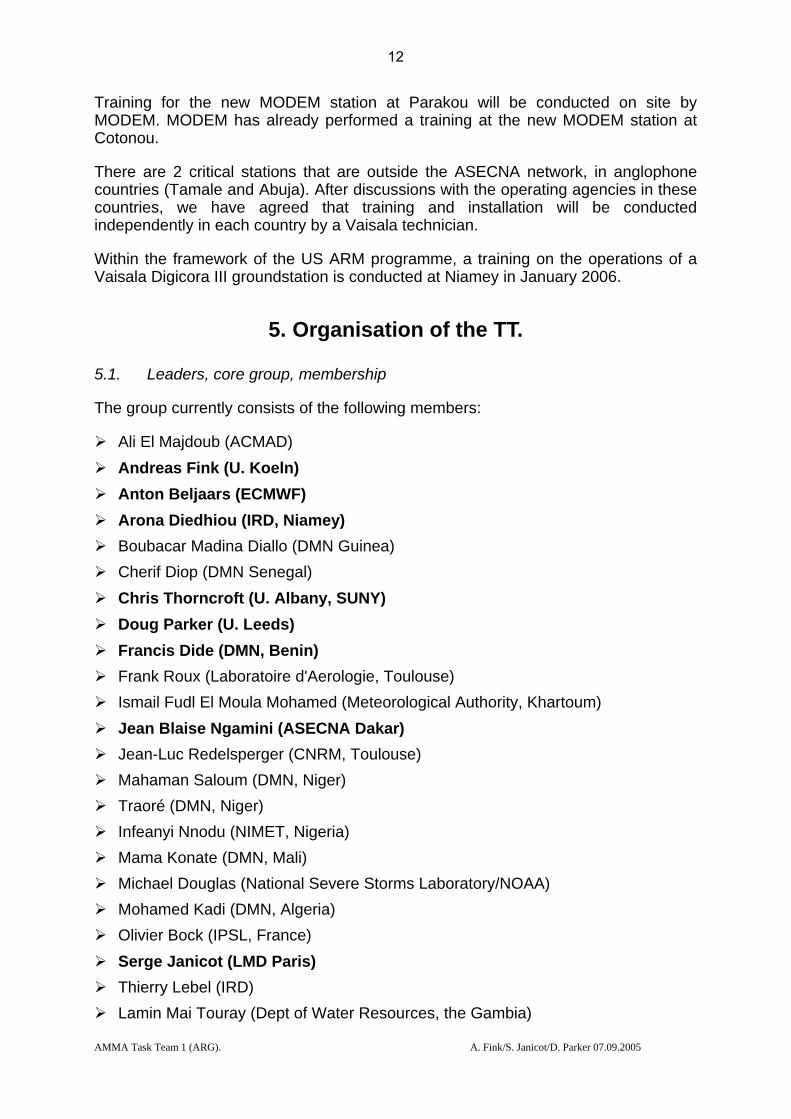
Training for the new MODEM station at Parakou will be conducted on site by MODEM. MODEM has already performed a training at the new MODEM station at Cotonou.
There are 2 critical stations that are outside the ASECNA network, in anglophone countries (Tamale and Abuja). After discussions with the operating agencies in these countries, we have agreed that training and installation will be conducted independently in each country by a Vaisala technician.
Within the framework of the US ARM programme, a training on the operations of a Vaisala Digicora III groundstation is conducted at Niamey in January 2006.
5. Organisation of the TT.
5.1. Leaders, core group, membership
The group currently consists of the following members:
Ali El Majdoub (ACMAD) Andreas Fink (U. Koeln) Anton Beljaars (ECMWF) Arona Diedhiou (IRD, Niamey) Boubacar Madina Diallo (DMN Guinea) Cherif Diop (DMN Senegal) Chris Thorncroft (U. Albany, SUNY) Doug Parker (U. Leeds) Francis Dide (DMN, Benin) Frank Roux (Laboratoire d'Aerologie, Toulouse) Ismail Fudl El Moula Mohamed (Meteorological Authority, Khartoum) Jean Blaise Ngamini (ASECNA Dakar) Jean-Luc Redelsperger (CNRM, Toulouse) Mahaman Saloum (DMN, Niger) Traoré (DMN, Niger) Infeanyi Nnodu (NIMET, Nigeria) Mama Konate (DMN, Mali) Michael Douglas (National Severe Storms Laboratory/NOAA) Mohamed Kadi (DMN, Algeria) Olivier Bock (IPSL, France) Serge Janicot (LMD Paris) Thierry Lebel (IRD) Lamin Mai Touray (Dept of Water Resources, the Gambia)
12

AMMA Task Team 1 (ARG). A. Fink/S. Janicot/D. Parker 07.09.2005
Zinede Minia (Meteorological Department, Ghana) The group is presently co-chaired by Andreas Fink and Serge Janicot.
Core group members are listed in bold. We have aimed to include representatives of relevant scientific communities, and from the major national and pan-national groups.
Each of the major funding agencies has its own management committee who are also represented in this TT.
5.2. Internal coordination
The internal communication is mainly performed via e-mail exchange and teleconferences among the core group
5.3. External diffusion of the information and reporting
Various reports have been produced and are available under the “Leeds” and “Cologne” web pages. The reporting to the AMMA ISSC is guaranteed by the ISSC membership of Andreas Fink .
Monitoring of the performance of stations in the network, and in the assimilation of data, is being conducted by ECMWF and can be viewed online at:
http://www.ecmwf.int/research/EU_projects/AMMA/index.html
5.4. Coordination with other TTs
The RS consumable deployment planning is closely coordinated with the SOP TT leaders (e.g. Jim Haywood and Doug Parker)
13

AMMA Task Team 1 (ARG). A. Fink/D. Parker 07/09/2005
6. ANNEX 1 CountryAreaDef StationNbr StationName Latitude Longitude AMMA priority EU priorityCOTE D'IVOIRE 65578 ABIDJAN 05 15N 03 56W 1 BETHIOPIA / ETHIOPIE 63450 ADDIS ABABA-BOLE 09 02N 38 45E 2 BNIGER 61024 AGADEZ 16 58N 07 59E 1 AMALI 61291 BAMAKO/SENOU 12 32N 07 57W 1 ACENTRAL AFRICAN REPUBLIC 64650 BANGUI 04 24N 18 31E 2 BGUINEA 61832 CONAKRY 09 34N 13 37W 1 BBENIN 65344 COTONOU 06 21N 02 23E 1 ASENEGAL 61641 DAKAR/YOFF 14 44N 17 30W 1 ACAMEROON / CAMEROUN 64910 DOUALA R.S. 04 01N 09 42E 1 BSUDAN / SOUDAN 62721 KHARTOUM 15 36N 32 33E 1 BCOTE D'IVOIRE 65548 MAN 07 23N 07 31W NIGERIA 65125 ABUJA 09 15N 07 00 E 1 ACHAD / TCHAD 64700 NDJAMENA 12 08N 15 02E 1 ACAMEROON / CAMEROUN 64870 NGAOUNDERE 07 21N 13 34E 2 BNIGER 61052 NIAMEY-AERO 13 29N 02 10E 1 AMAURITANIA / MAURITANIE 61415 NOUADHIBOU 20 56N 15 57W 2 BMAURITANIA / MAURITANIE 61442 NOUAKCHOTT 18 06N 17 02W 2 BBURKINA FASO 65503 OUAGADOUGOU 12 21N 01 31W 2 BBENIN 65330 PARAKOU 09 21N 02 37E 1 ACAPE VERDE / CAP-VERT 8594 SAL 16 44N 22 57W 1 BCHAD / TCHAD 64750 SARH 09 09N 18 23E 2 BGHANA 65418 TAMALE 09 30N 00 51W 1 AALGERIA / ALGERIE 60680 TAMANRASSET 22 48N 05 26E 1 ASENEGAL 61687 TAMBACOUNDA 13 46N 13 41W 2 BMALI 61202 TESSALIT 20 12N 00 59E 1 BMALI 61223 TOMBOUCTOU 16 43N 03 00W 1 A ASECNA TRAINING DKR ASECNA TRAINING NIM
Table 1: Radiosonde stations in the AMMA region, and their operational priorities, for AMMA EOP (1-2) and for AMMA-EU (A-B).
14
AMMA Task Team 1 (ARG). A. Fink/D. Parker 07/09/2005
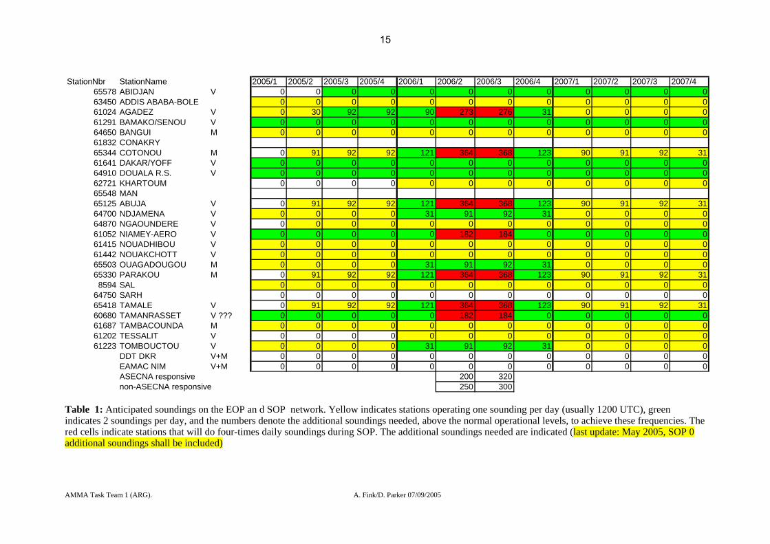
StationNbr StationName 2005/1 2005/2 2005/3 2005/4 2006/1 2006/2 2006/3 2006/4 2007/1 2007/2 2007/3 2007/4
65578 ABIDJAN V 0 0 0 0 0 0 0 0 0 0 0 063450 ADDIS ABABA-BOLE 0 0 0 0 0 0 0 0 0 0 0 061024 AGADEZ V 0 30 92 92 90 273 276 31 0 0 0 061291 BAMAKO/SENOU V 0 0 0 0 0 0 0 0 0 0 0 064650 BANGUI M 0 0 0 0 0 0 0 0 0 0 0 061832 CONAKRY65344 COTONOU M 0 91 92 92 121 364 368 123 90 91 92 3161641 DAKAR/YOFF V 0 0 0 0 0 0 0 0 0 0 0 064910 DOUALA R.S. V 0 0 0 0 0 0 0 0 0 0 0 062721 KHARTOUM 0 0 0 0 0 0 0 0 0 0 0 065548 MAN65125 ABUJA V 0 91 92 92 121 364 368 123 90 91 92 3164700 NDJAMENA V 0 0 0 0 31 91 92 31 0 0 0 064870 NGAOUNDERE V 0 0 0 0 0 0 0 0 0 0 0 061052 NIAMEY-AERO V 0 0 0 0 0 182 184 0 0 0 0 061415 NOUADHIBOU V 0 0 0 0 0 0 0 0 0 0 0 061442 NOUAKCHOTT V 0 0 0 0 0 0 0 0 0 0 0 065503 OUAGADOUGOU M 0 0 0 0 31 91 92 31 0 0 0 065330 PARAKOU M 0 91 92 92 121 364 368 123 90 91 92 318594 SAL 0 0 0 0 0 0 0 0 0 0 0 0
64750 SARH 0 0 0 0 0 0 0 0 0 0 0 065418 TAMALE V 0 91 92 92 121 364 368 123 90 91 92 3160680 TAMANRASSET V ??? 0 0 0 0 0 182 184 0 0 0 0 061687 TAMBACOUNDA M 0 0 0 0 0 0 0 0 0 0 0 061202 TESSALIT V 0 0 0 0 0 0 0 0 0 0 0 061223 TOMBOUCTOU V 0 0 0 0 31 91 92 31 0 0 0 0
DDT DKR V+M 0 0 0 0 0 0 0 0 0 0 0 0EAMAC NIM V+M 0 0 0 0 0 0 0 0 0 0 0 0ASECNA responsive 200 320non-ASECNA responsive 250 300
Table 1: Anticipated soundings on the EOP an d SOP network. Yellow indicates stations operating one sounding per day (usually 1200 UTC), green indicates 2 soundings per day, and the numbers denote the additional soundings needed, above the normal operational levels, to achieve these frequencies. The red cells indicate stations that will do four-times daily soundings during SOP. The additional soundings needed are indicated (last update: May 2005, SOP 0 additional soundings shall be included)
15

AMMA Task Team 1 (ARG). A. Fink/D. Parker 07/09/2005
7. ANNEX 2 AMMA Radiosonde Task Group: Implementation Strategy, last updated: last update: 07/09/2005 by A. Fink
Immediate priorities: 1. Upgrade of Communications/IT-Equipment on key stations in existing network (by 09/05). 2. Installation of new stations at Cotonou, Parakou, Abuja and Tamale (by 05/05-12/05). Cotonou is
active since 05/2005. Upgrade priorities (by the end of 2005): 1. Replacement of existing Digicora I stations by refurbished Digicora II stations (except Dakar that
will be equipped with a new Digicora III MW21) in the ASECNA network (by 12/05). 2. Upgrade of existing Digicora II stations in the ASECNA network (by 12/05). 3. Replacement of key STAR stations by refurbished Digicora II stations (by 12/05). 4. Implement training of operators on the VAISALA/MODEM groundstations, on VAISALA
(RS92) and MODEM (M2K2) PTU GPS sondes and on DCPs (by 12/05)
16

AMMA Task Team 1 (ARG). A. Fink/D. Parker 07/09/2005
Status of existing stations:
Digicora MW11 (I) stations
Name, code Country Operator AMMA Priority/ EU Priority
Addis AbabaGCOS station
Ethiopia P2/B
Status, May 2004 Proposed actions
Date, cost, source
Groundstation Digicora None (priority 2)
Communications/IT-Equipment
?? None
Gas generation ?? None
Building ?? None
Name, code Country Operator AMMA Priority/ EU Priority
Agadez, 61024 Niger ASECNA P1/A
Status, July 2005 Proposed actions Date, cost, source
Groundstation Digicora MW11 (1994) with MF12
Upgrade to RS92 (Refurbished Digicora II)
12/05, 27 kE, ASECNA AMMA-EU
Communications/IT-Equipment
VSAT Cable/Radiolink to VSAT building;
12/05, 4 kE, ASECNA/ AMMA-EU
Gas generation GIP 3, two old ones None for twice-daily soundings
17

AMMA Task Team 1 (ARG). A. Fink/D. Parker 07/09/2005
Building OK, but old (1974) none
Power Supply Less reliable Power Generator or UPS
ASECNA AMMA-EU
Name, code Country Operator AMMA Priority/ EU Priority
Dakar, 61641GCOS station
Senegal ASECNA P1/A
Status, May 2004 Proposed actions
Date, cost, source
Groundstation Digicora I MW11 (1989) and STAR
New Digicora III MW21
09/05, 52 kE, ASECNA AMMA-EU
Communications/IT-Equipment/
No automatic transmission to CAT,
Automatic transmission to CAT via radiolink
12/05, 4 kE, ASECNA
Gas generation GIP 3 (Electrolyser unserviceable)
New Electrolyser US GCOS programme
Building OK None
Name, code Country Operator AMMA Priority/ EU Priority
Douala, 64910(GCOS station)
Cameroon ASECNA P1/B
Status, May 2004 Proposed actions
Date, cost, source
Groundstation Digicora MW11 (1986)
Upgrade to RS92 (Refurbished Digicora II)
12/05, 13 kE, ASECNA, GCOS support
18
AMMA Task Team 1 (ARG). A. Fink/D. Parker 07/09/2005
Communications/IT-Equipment
No automatic transmission to CAT,
Automatic transmission to CAT via radiolink
5 kE, ASECNA
Gas generation GIP 3 None
Building OK None
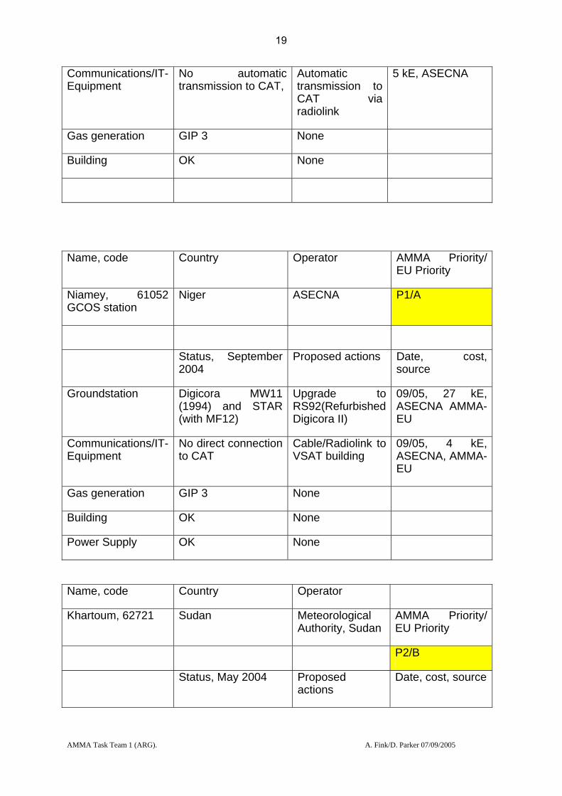
Name, code Country Operator AMMA Priority/ EU Priority
Niamey, 61052GCOS station
Niger ASECNA P1/A
Status, September 2004
Proposed actions Date, cost, source
Groundstation Digicora MW11 (1994) and STAR (with MF12)
Upgrade to RS92(Refurbished Digicora II)
09/05, 27 kE, ASECNA AMMA-EU
Communications/IT-Equipment
No direct connection to CAT
Cable/Radiolink to VSAT building
09/05, 4 kE, ASECNA, AMMA-EU
Gas generation GIP 3 None
Building OK None
Power Supply OK None
Name, code Country Operator
Khartoum, 62721 Sudan Meteorological Authority, Sudan
AMMA Priority/ EU Priority
P2/B
Status, May 2004 Proposed actions
Date, cost, source
19
AMMA Task Team 1 (ARG). A. Fink/D. Parker 07/09/2005
Groundstation Digicora None
Communications/IT-Equipment
Unserviceable None
Gas generation ?? None
Building ?? None
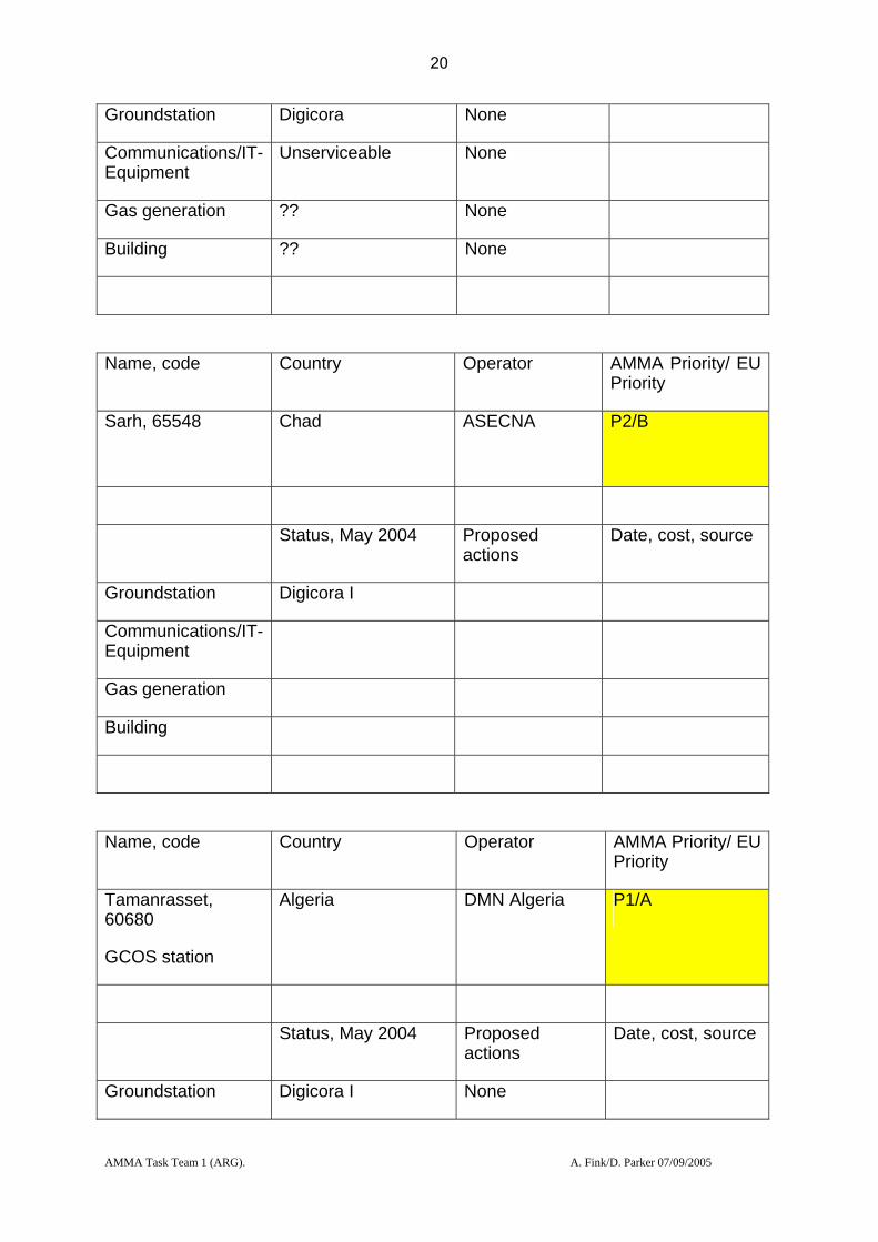
Name, code Country Operator AMMA Priority/ EU Priority
Sarh, 65548
Chad ASECNA P2/B
Status, May 2004 Proposed actions
Date, cost, source
Groundstation Digicora I
Communications/IT-Equipment
Gas generation
Building
Name, code Country Operator AMMA Priority/ EU Priority
Tamanrasset, 60680
GCOS station
Algeria DMN Algeria P1/A
Status, May 2004 Proposed actions
Date, cost, source
Groundstation Digicora I None
20

AMMA Task Team 1 (ARG). A. Fink/D. Parker 07/09/2005
Communications/IT-Equipment
?? None
Gas generation ?? None
Building ?? None
Name, code Country Operator AMMA Priority/ EU Priority
Tessalit, 61202 Mali ASECNA Abandoned due to logistic problems
Status, May 2004 Proposed actions
Date, cost, source
Groundstation Digicora I Upgrade to RS92 (Refurbished Digicora II)
12/05, 27 kE, ASECNA AMMA-EU
Communications/IT-Equipment
None 09/05, 7,5 kE, ASECNA AMMA-EU
Gas generation Two new GIP 3 12/05 12 kE, , ASECNA AMMA-EU
Building To be determined
Name, code Country Operator AMMA Priority/ EU Priority
Tombouctou, 61223 Mali ASECNA P1/A
Status, May 2004 Proposed actions Date, cost, source
21

AMMA Task Team 1 (ARG). A. Fink/D. Parker 07/09/2005
Groundstation Digicora MW11 (1994)
Upgrade to RS92(Refurbished Digicora II)
12/05, 27 kE, ASECNA AMMA-EU
Communications/IT-Equipment
VSAT Cable/Radiolink to VSAT building;
12/05, 4 kE, ASECNA/ AMMA-EU
Gas generation GIP 3 None
Building OK None
Digicora MW15 (II) stations
Name, code Country Operator AMMA Priority/ EU Priority
Abidjan, 65578
(GCOS stations)
Cote d’Ivoire ASECNA P1/B
Status, May 2004 Proposed actions
Date, cost, source
Groundstation Digicora II Upgrade to RS92
Asap, NOAA/GCOS
Communications/IT-Equipment
No direct connection to CAT
Install 12/05, 4 kE, ASECNA, AMMA-EU
Gas generation Electrolyser destroyed by June 2001 accident
GIP 3 needed 12/05 12 kE, ASECNA AMMA-EU
Building Under construction Complete construction
ASECNA
Name, code Country Operator AMMA Priority/ EU Priority
22

AMMA Task Team 1 (ARG). A. Fink/D. Parker 07/09/2005
Man, 65548
Cote d’Ivoire ASECNA Status of the station unclear
Status, May 2004 Proposed actions
Date, cost, source
Groundstation Digicora I
Communications/IT-Equipment
Gas generation
Building
Name, code Country Operator AMMA Priority/ EU Priority
N’Djamena, 64700 Chad ASECNA P1/A
Status, May 2004 Proposed actions
Date, cost, source
Groundstation Digicora MW15 (1999)
Upgrade to RS92
12/05, 10 kE, ASECNA AMMA-EU
Communications/IT-Equipment
No automatic transmission to CAT,
Automatic transmission to CAT via radiolink
12/05, 4 kE, ASECNA
Gas generation GIP 3 None
Building OK None
Name, code Country Operator AMMA Priority/ EU Priority
23
AMMA Task Team 1 (ARG). A. Fink/D. Parker 07/09/2005
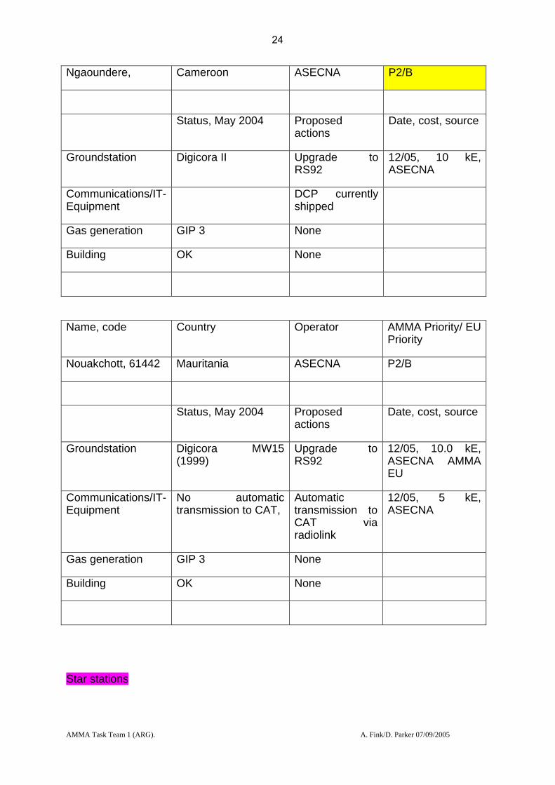
Ngaoundere, Cameroon ASECNA P2/B
Status, May 2004 Proposed actions
Date, cost, source
Groundstation Digicora II Upgrade to RS92
12/05, 10 kE, ASECNA
Communications/IT-Equipment
DCP currently shipped
Gas generation GIP 3 None
Building OK None
Name, code Country Operator AMMA Priority/ EU Priority
Nouakchott, 61442 Mauritania ASECNA P2/B
Status, May 2004 Proposed actions
Date, cost, source
Groundstation Digicora MW15 (1999)
Upgrade to RS92
12/05, 10.0 kE, ASECNA AMMA EU
Communications/IT-Equipment
No automatic transmission to CAT,
Automatic transmission to CAT via radiolink
12/05, 5 kE, ASECNA
Gas generation GIP 3 None
Building OK None
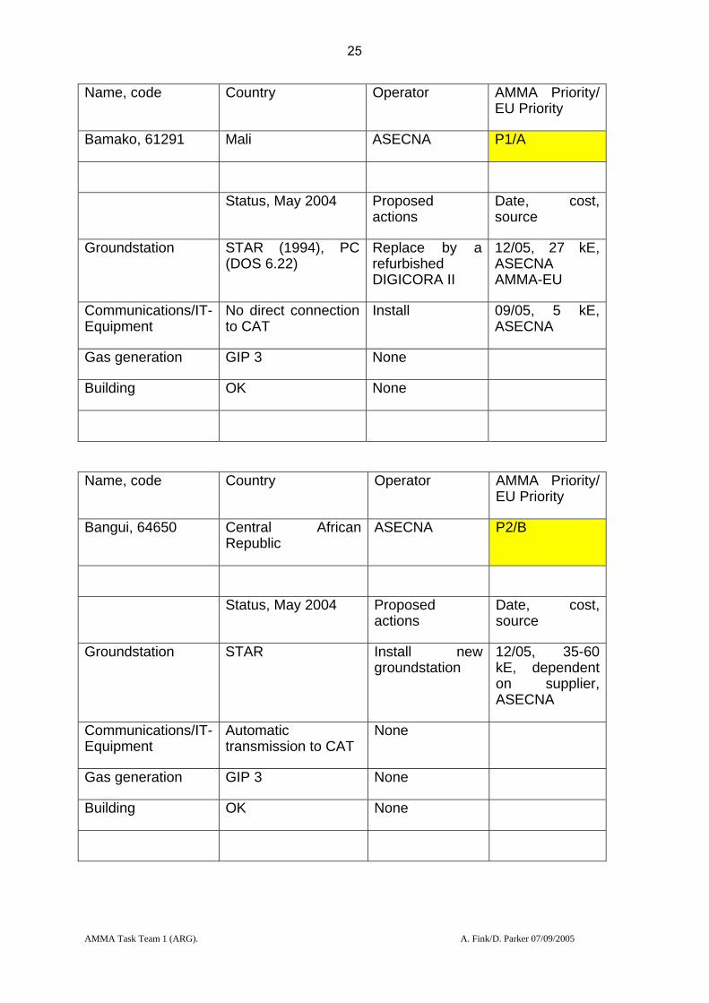
Star stations
24
AMMA Task Team 1 (ARG). A. Fink/D. Parker 07/09/2005
Name, code Country Operator AMMA Priority/ EU Priority
Bamako, 61291 Mali ASECNA P1/A
Status, May 2004 Proposed actions
Date, cost, source
Groundstation STAR (1994), PC (DOS 6.22)
Replace by a refurbished DIGICORA II
12/05, 27 kE, ASECNA AMMA-EU
Communications/IT-Equipment
No direct connection to CAT
Install 09/05, 5 kE, ASECNA
Gas generation GIP 3 None
Building OK None
Name, code Country Operator AMMA Priority/ EU Priority
Bangui, 64650 Central African Republic
ASECNA P2/B
Status, May 2004 Proposed actions
Date, cost, source
Groundstation STAR Install new groundstation
12/05, 35-60 kE, dependent on supplier, ASECNA
Communications/IT-Equipment
Automatic transmission to CAT
None
Gas generation GIP 3 None
Building OK None
25

AMMA Task Team 1 (ARG). A. Fink/D. Parker 07/09/2005
Name, code Country Operator AMMA Priority/ EU Priority
Nouadhibou, 61415 Mauritania ASECNA P2/B
Status, May 2004 Proposed actions
Date, cost, source
Groundstation STAR (1994), Install new groundstation
12/05, 35-60 kE, dependent on supplier, ASECNA
Communications/IT-Equipment
Gas generation
Building
Name, code Country Operator AMMA Priority/ EU Priority
Ouagadougou, 65503
Burkina Faso ASECNA P2/B
Status, May 2004 Proposed actions
Date, cost, source
Groundstation STAR Replace by a refurbished DIGICORA II groundstation
12/05, 27 kE, ASECNA AMMA EU
Communications/IT-Equipment
Automatic transmission to CAT
None
Gas generation GIP 3 None
Building OK None
26

AMMA Task Team 1 (ARG). A. Fink/D. Parker 07/09/2005
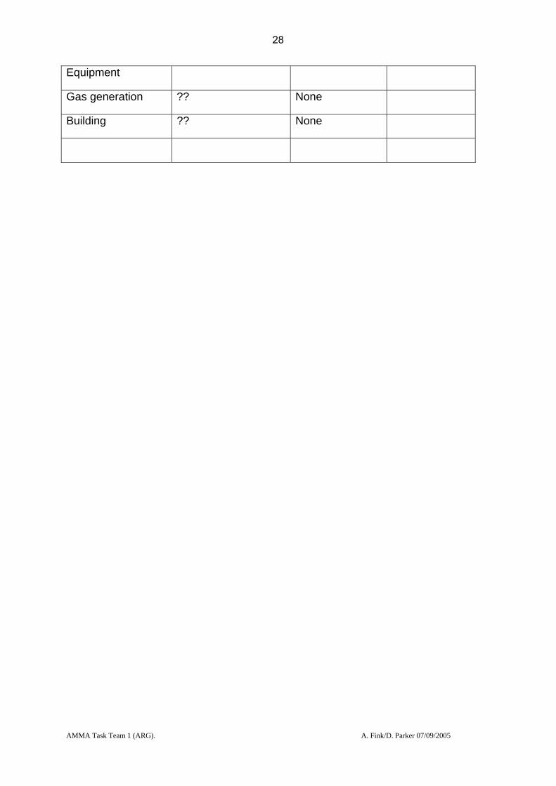
Name, code Country Operator AMMA Priority/ EU Priority
Tamba, 61687 Senegal ASECNA P2/B
Status, May 2004 Proposed actions
Date, cost, source
Groundstation STAR Install new groundstation
12/05, 35-60 kE, dependent on supplier, ASECNA
Communications/IT-Equipment
??? None
Gas generation GIP 3 None
Building OK None
others
Name, code Country Operator AMMA Priority/ EU Priority
Sal, 08594
GCOS station
Cape Verde Cape Verde Meteorological Service
P1/B
Status, May 2004 Proposed actions
Date, cost, source
Groundstation ATIR US INC (radiotheodolite)
None
Communications/IT- ?? None
27
AMMA Task Team 1 (ARG). A. Fink/D. Parker 07/09/2005
Equipment
Gas generation ?? None
Building ?? None
28

AMMA Task Team 1 (ARG). A. Fink/D. Parker 07/09/2005
Status of new stations:
Name, code Country Operator AMMA Priority/ EU Priority
Abuja, 65125 Nigeria NIMET P1/A
Status, July 2005 Proposed actions
Date, cost, source
Groundstation None New DIGICORA III MW 21
53 kE, AMMA EU NIMET
Communications/IT-Equipment
To be reviewed DCP is presently shipped to Nigeria
Gas generation None Two new GIP 3 12 kE AMMA EU NIMET
Building None To be constructed
NIMET
Power Supply To be reviewed To be reviewed
Name, code Country Operator AMMA Priority/ EU Priority
Cotonou, 65344 Benin ASECNA P1/A
Status, July 2005 Proposed actions Date, cost, source
Groundstation MODEM SR2K2 None
Communications/IT-Equipment
No automatic transmission to CAT, Manual transmission not working
Reprogramming CAOB computer to enable manual transmission; next Automatic transmission to CAT via radiolink
09/05, 4 kE, ASECNA
Gas generation GIP 3 None
29

AMMA Task Team 1 (ARG). A. Fink/D. Parker 07/09/2005
Building OK, amendments
completed
None
Power Supply OK, no outages None
Name, code Country Operator AMMA Priority/ EU Priority
Parakou, 65330 Benin DMN Bénin P1/A
Status, July 2005 Proposed actions Date, cost, source
Groundstation None MODEM SR2K2, call for tender released in July 2005
09/05, 35 kE, AMMA-EU DMN Benin
Communications/IT-Equipment
None DCP currently shipped
Gas generation Gip 3 None
Building OK None
Power Supply Reliable, outages infrequent
Supply of an UPS 09/05, AMMA-EU DMN Benin
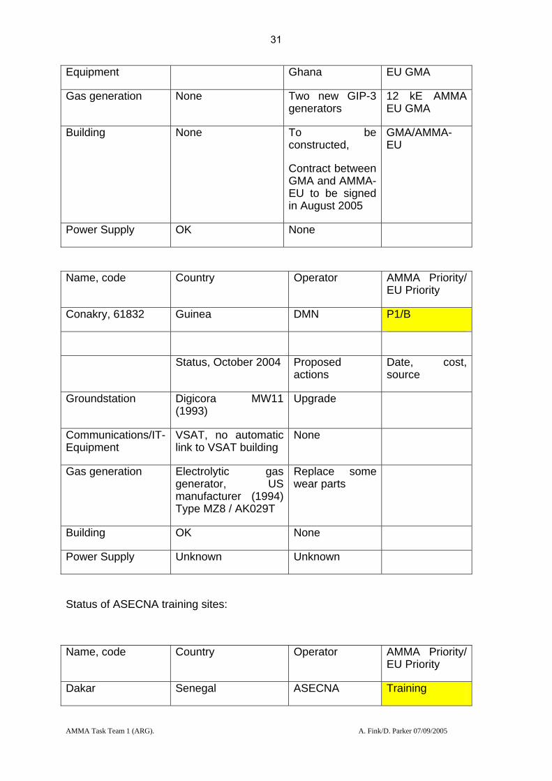
Name, code Country Operator AMMA Priority/ EU Priority
Tamale, 65418 Ghana Meteorological Department, Ghana
P1/A
Status, July 2005 Proposed actions Date, cost, source
Groundstation None New DIGICORA III MW 21
53 kE 09/05 AMMA-EU GMA
Communications/IT- VSAT DCP is presently shipped to
7,5 kE AMMA
30
AMMA Task Team 1 (ARG). A. Fink/D. Parker 07/09/2005
Equipment Ghana EU GMA
Gas generation None Two new GIP-3 generators
12 kE AMMA EU GMA
Building None To be constructed,
Contract between GMA and AMMA-EU to be signed in August 2005
GMA/AMMA-EU
Power Supply OK None
Name, code Country Operator AMMA Priority/ EU Priority
Conakry, 61832 Guinea DMN P1/B
Status, October 2004 Proposed actions
Date, cost, source
Groundstation Digicora MW11 (1993)
Upgrade
Communications/IT-Equipment
VSAT, no automatic link to VSAT building
None
Gas generation Electrolytic gas generator, US manufacturer (1994) Type MZ8 / AK029T
Replace some wear parts
Building OK None
Power Supply Unknown Unknown
Status of ASECNA training sites:
Name, code Country Operator AMMA Priority/ EU Priority
Dakar Senegal ASECNA Training
31

AMMA Task Team 1 (ARG). A. Fink/D. Parker 07/09/2005
Status, October 2004 Proposed actions
Date, cost, source
Groundstation Digicora I and Star Refurbished Digicora II
27 kE, AMMA EU NIMET
Name, code Country Operator AMMA Priority/ EU Priority
Niamey Niger ASECNA Training
Status, October 2004
Proposed actions Date, cost, source
Groundstation Digicora I and Star Refurbished Digicora II
09/05, …, ACI/CNRS (France)
32
AMMA Task Team 1 (ARG). A. Fink/D. Parker 07/09/2005
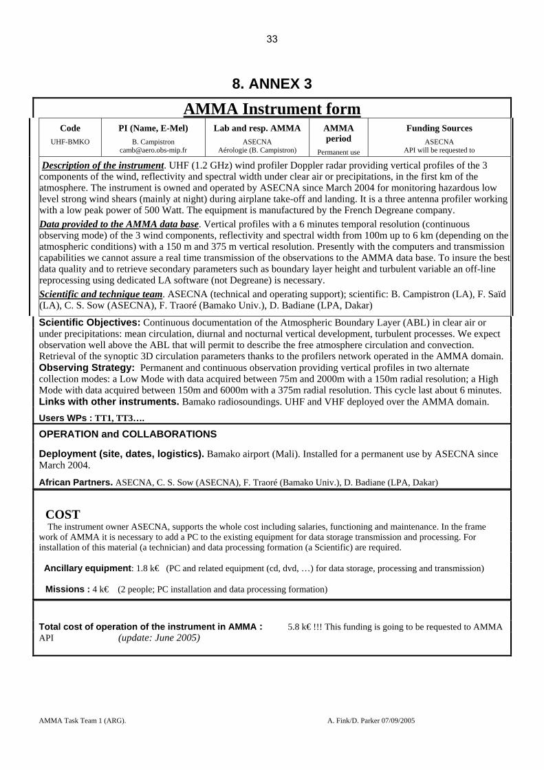
8. ANNEX 3
AMMA Instrument form Code
UHF-BMKO
PI (Name, E-Mel) B. Campistron
Lab and resp. AMMA ASECNA
Aérologie (B. Campistron)
AMMA period
Permanent use
Funding Sources ASECNA
API will be requested to
Description of the instrument. UHF (1.2 GHz) wind profiler Doppler radar providing vertical profiles of the 3 components of the wind, reflectivity and spectral width under clear air or precipitations, in the first km of the atmosphere. The instrument is owned and operated by ASECNA since March 2004 for monitoring hazardous low level strong wind shears (mainly at night) during airplane take-off and landing. It is a three antenna profiler working with a low peak power of 500 Watt. The equipment is manufactured by the French Degreane company. Data provided to the AMMA data base. Vertical profiles with a 6 minutes temporal resolution (continuous observing mode) of the 3 wind components, reflectivity and spectral width from 100m up to 6 km (depending on the atmospheric conditions) with a 150 m and 375 m vertical resolution. Presently with the computers and transmission capabilities we cannot assure a real time transmission of the observations to the AMMA data base. To insure the best data quality and to retrieve secondary parameters such as boundary layer height and turbulent variable an off-line reprocessing using dedicated LA software (not Degreane) is necessary. Scientific and technique team. ASECNA (technical and operating support); scientific: B. Campistron (LA), F. Saïd (LA), C. S. Sow (ASECNA), F. Traoré (Bamako Univ.), D. Badiane (LPA, Dakar)
Scientific Objectives: Continuous documentation of the Atmospheric Boundary Layer (ABL) in clear air or under precipitations: mean circulation, diurnal and nocturnal vertical development, turbulent processes. We expect observation well above the ABL that will permit to describe the free atmosphere circulation and convection. Retrieval of the synoptic 3D circulation parameters thanks to the profilers network operated in the AMMA domain. Observing Strategy: Permanent and continuous observation providing vertical profiles in two alternate collection modes: a Low Mode with data acquired between 75m and 2000m with a 150m radial resolution; a High Mode with data acquired between 150m and 6000m with a 375m radial resolution. This cycle last about 6 minutes. Links with other instruments. Bamako radiosoundings. UHF and VHF deployed over the AMMA domain. Users WPs : TT1, TT3….
OPERATION and COLLABORATIONS
Deployment (site, dates, logistics). Bamako airport (Mali). Installed for a permanent use by ASECNA since March 2004.
African Partners. ASECNA, C. S. Sow (ASECNA), F. Traoré (Bamako Univ.), D. Badiane (LPA, Dakar)
COST The instrument owner ASECNA, supports the whole cost including salaries, functioning and maintenance. In the frame
work of AMMA it is necessary to add a PC to the existing equipment for data storage transmission and processing. For installation of this material (a technician) and data processing formation (a Scientific) are required.
Ancillary equipment: 1.8 k€ (PC and related equipment (cd, dvd, …) for data storage, processing and transmission)
Missions : 4 k€ (2 people; PC installation and data processing formation)
Total cost of operation of the instrument in AMMA : 5.8 k€ !!! This funding is going to be requested to AMMA API (update: June 2005)
33
AMMA Task Team 2a Reference Document
Colin Lloyd, Chris Taylor
Version 2.2
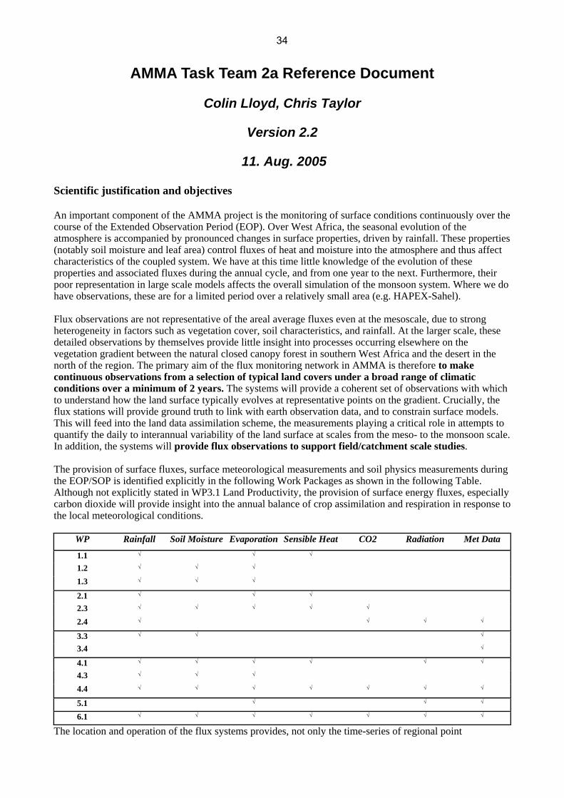
11. Aug. 2005 Scientific justification and objectives An important component of the AMMA project is the monitoring of surface conditions continuously over the course of the Extended Observation Period (EOP). Over West Africa, the seasonal evolution of the atmosphere is accompanied by pronounced changes in surface properties, driven by rainfall. These properties (notably soil moisture and leaf area) control fluxes of heat and moisture into the atmosphere and thus affect characteristics of the coupled system. We have at this time little knowledge of the evolution of these properties and associated fluxes during the annual cycle, and from one year to the next. Furthermore, their poor representation in large scale models affects the overall simulation of the monsoon system. Where we do have observations, these are for a limited period over a relatively small area (e.g. HAPEX-Sahel). Flux observations are not representative of the areal average fluxes even at the mesoscale, due to strong heterogeneity in factors such as vegetation cover, soil characteristics, and rainfall. At the larger scale, these detailed observations by themselves provide little insight into processes occurring elsewhere on the vegetation gradient between the natural closed canopy forest in southern West Africa and the desert in the north of the region. The primary aim of the flux monitoring network in AMMA is therefore to make continuous observations from a selection of typical land covers under a broad range of climatic conditions over a minimum of 2 years. The systems will provide a coherent set of observations with which to understand how the land surface typically evolves at representative points on the gradient. Crucially, the flux stations will provide ground truth to link with earth observation data, and to constrain surface models. This will feed into the land data assimilation scheme, the measurements playing a critical role in attempts to quantify the daily to interannual variability of the land surface at scales from the meso- to the monsoon scale. In addition, the systems will provide flux observations to support field/catchment scale studies. The provision of surface fluxes, surface meteorological measurements and soil physics measurements during the EOP/SOP is identified explicitly in the following Work Packages as shown in the following Table. Although not explicitly stated in WP3.1 Land Productivity, the provision of surface energy fluxes, especially carbon dioxide will provide insight into the annual balance of crop assimilation and respiration in response to the local meteorological conditions.
WP Rainfall Soil Moisture Evaporation Sensible Heat CO2 Radiation Met Data
1.1 √ √ √
1.2 √ √ √
1.3 √ √ √
2.1 √ √ √
2.3 √ √ √ √ √
2.4 √ √ √ √
3.3 √ √ √
3.4 √
4.1 √ √ √ √ √ √
4.3 √ √ √
4.4 √ √ √ √ √ √ √
5.1 √ √ √
6.1 √ √ √ √ √ √ √
The location and operation of the flux systems provides, not only the time-series of regional point
34

measurements of sensible and latent heat and carbon dioxide fluxes for the above work packages, but also provides relevant long-term data to vegetation, soil moisture, energy balance and aerosol experiments at each of the supersites. There is therefore very strong links between TT2a and TT2b, TT3, TT4 and TT5. 2. Observing Strategy a.) Overall Strategy The primary aim above can be met by addressing the different energy balances of the typical vegetation surfaces in the region and so the deployment of the flux stations has attempted within the overall budget constraints to encompass these differences. Of overall concern is the efficient collection of continuous data during the EOP – an effort that would be compromised by attempting a transect approach to the measurements. The scientific need informed the design of a multi-site network of simple and robust heat flux stations capable of running with minimum maintenance throughout the EOP. This network comprises four super sites, encompassing the north-south rainfall gradient and the typical vegetation covers found within a super site. The sites are based around existing measurements and experimental infrastructure. The sites are in the Hombori-Gao region of N. Mali (5-300 mm annual rainfall), the Niamey region of Niger (550 mm), the Upper Oueme catchment in Benin (1200 mm), and the Ejura region of Ghana (1300 mm, during 2 wet seasons within the year). The success of funding bids to both NERC (UK) and the EU has provided the flexibility to convert several of the heat flux stations to full eddy correlation systems measuring water and carbon fluxes. These conversions are necessary over certain surfaces where the heterogeneity of the vegetation and soil surfaces severely limits the ability of simple heat flux stations in combination with energy balance considerations to provide believable estimates of evaporation. Even the interpretation of sensible heat flux measurements is complicated by the heterogeneity of these surfaces and an independent measure of evaporation allows better quality control of the data. Additional full eddy correlation systems have been funded from other sources (API? and CLASSIC). b.) Modelling and satellite observations The surface flux observations will provide an important source of ground truth for land surface modelling and satellite efforts in AMMA. They will provide:
1) the means to develop and calibrate land surface schemes at the point scale 2) a characterisation of ‘typical’ land surface functioning across the vegetation gradient for comparison with surface scheme behaviour in NWP and climate models 3) observations which can be compared with both remotely-sensed data and land surface schemes forced by remotely-sensed data
In the cases of (2) and (3), the spatial scales do not correspond, the flux observations being sub-grid and sub-pixel scale. On any particular day, direct comparisons might be poor, due for example to spatial variability of rainfall. However, in many cases the behaviour of the surface at the larger scale should resemble that which is observed locally when averaged over longer periods, or when account is taken of spatial variability in vegetation. Given the lack of available ground truth fluxes across the region for developing satellite and surface modelling schemes, use of the flux data will increase confidence in results from these larger scale tools. The sites have been chosen to capture a broad range of surface conditions found in the monsoon region. The systems will produce standard forcing variables for land surface schemes (summarised in Table 2) as well as the turbulent fluxes for verification. These will be available at 30 minute resolution for the duration of the EOP. Additional data will be made available describing site – vegetation coverage, soil type etc. It has been agreed that Quality Controlled data will be available 6 months after the collection from the field sites. Non quality controlled data can be made available upon request as soon as it has been added to the flux database. Quality control will consist of isolation of physically unrealistic values together with gap-filling based on protocols developed within the CarboEurope programme.
35

c.) List of sites, instruments and relevant maps
Mali Supersite The northernmost main site is in the region of Hombori-Gao, Mali, where a heat flux station (HFS) will be located at a largely unvegetated desert site at Bamba ( 50 -100mm annual precipitation, >95% sand soil). In the absence of existing AMMA activity in a completely unvegetated area, this should provide relevant ground truth for desert conditions. The area around Hombori ( 300 mm annual precipitation) is largely either low-intensity grazed savannah grassland or laterite areas with little vegetation. Isolated areas of open acacia forest are also present. An HFS will be established over an extensive laterite pan (common across the region) while complete CO2/evaporation/Heat flux stations (Mk4) will be installed over both a typical area of grassland and an open forest site. Niger Supersite A Sahelian region main site will be sited around Wankama, to the east of Niamey, Niger where the annual precipitation is around 600 mm. Here the typical surfaces consist of Millet (the local grain crop), heavily grazed fallow bush , degraded fallow bush and laterite pans, mostly covered with poor to good dense vegetation strips known as Tiger Bush. Methodological difficulties with interpreting Tiger Bush energy fluxes identified during HAPEX-Sahel have not been resolved sufficiently in the intervening period for routine data monitoring practice, and the surface will be excluded from the flux station deployment. Some insight will be gained from consideration of the laterite surface at the northern Mali site. An API funded CO2/H2O flux station will be installed over an area of fallow bush. Another API funded CO2/H2O system will operate over an area of Millet to characterise the heat, evaporation and carbon dioxide fluxes. An HFS system will remain in reserve in Niamey to provide spares for any system in the network that inevitably will have sensor or logging failure during the 30 months of continuous operation that these systems will undertake. This system, will however, be used on a campaign basis alongside the tower measurements of “erosion” flux (TT2b) to provide the micrometeorological parameters that define and explain the turbulent transport of dust and aerosols. Benin Supersite A Soudanian region main site will be sited around Djougou in the Ouémé catchment, northern Benin (1200mm annual precipitation). The vegetation surfaces here are typically open scrub forest and croplands with some isolated areas of forest. The small scale homogeneity of the region croplands presents difficulties in evaluating evaporation from a HFS System owing to the point nature of the radiation and soil heat flux measurements compared to the field scale of the sensible heat fluxes. In response to TT5 requests for complete latent heat and CO2 flux measurements, funds will be sought to augment one HFS with a Licor Li7500 H2O/CO2 instrument. A Mk4 System will measure CO2/H2O and Sensible Heat fluxes over a typical forest site. The single HFS system will be deployed over a more homogeneous crop or open scrub grassland site where energy balance considerations can be adequately applied. The flux systems to be installed at the above locations consist of the following instruments/measurement parameters are shown in the following table. (See Table 5 for symbol explanation). Instrument Sensor Measurements AFI Flux system Campbell CSAT3 Sonic Anemometer u v w Wd Ts H M u* z0 z/L +Variances Licor 7500 IRGA CO2c H2Oc Fc LE Kipp & Zonen CNR1 Radiation Sin Sout Lin Lout al Rn Vaisala HMP45 Ta RH Young Propeller Anemometer Ws Wd Rimco 0.5mm Raingauge Pg Pd Pi TDR Soil Moisture Profile VWC x6 Soil Temperature Profile Tsoil x6 HFS Solent R3-50 Sonic Anemometer u v w Wd Ts H M u* z0 z/L +Variances Vaisala WTX510 Weather Station Ta RH Pr Ws Wd Pg Pd Pi Kipp & Zonen CNR1 Radiation Sin Sout Lin Lout al Rn Campbell CS616 Soil moisture VWC x2 Campbell T107 Soil thermistors Tsoil x2 Rimco 0.5mm raingauge Pg Pd Pi MK4 =above + following (Embedded IRGA) CO2c H2Oc Fc LE Table 2
36
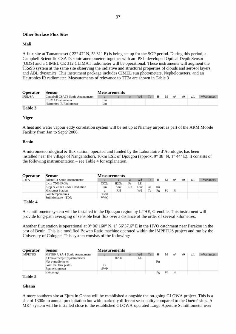
Other Surface Flux Sites Mali A flux site at Tamanrasset ( 22° 47’ N, 5° 31' E) is being set up for the SOP period. During this period, a Campbell Scientific CSAT3 sonic anemometer, together with an IPSL-developed Optical Depth Sensor (ODS) and a CIMEL CE 312 CLIMAT radiometer will be operational. These instruments will augment the TReSS system at the same site observing the radiative and structural properties of clouds and aerosol layers, and ABL dynamics. This instrument package includes CIMEL sun photometers, Nephelometers, and an Heitronics IR radiometer. Measurements of relevance to TT2a are shown in Table 3 Operator Sensor Measurements IPSL/SA Campbell CSAT3 Sonic Anemometer u v w Wd Ts H M u* z0 z/L +Variances CLIMAT radiometer Lin Heitronics IR Radiometer Lin Table 3 Niger A heat and water vapour eddy correlation system will be set up at Niamey airport as part of the ARM Mobile Facility from Jan to Sept? 2006. Benin A micrometeorological & flux station, operated and funded by the Laboratoire d’Aerologie, has been installed near the village of Nangantchori, 10km ESE of Djougou (approx. 9° 38’ N, 1° 44’ E). It consists of the following instrumentation – see Table 4 for explanation. Operator Sensor Measurements L d’A Solent R1 Sonic Anemometer u v w Wd Ts H M u* z0 z/L +Variances Licor 7500 IRGA CO2c H2Oc Fc LE Kipp & Zonen CNR1 Radiation Sin Sout Lin Lout al Rn Micromet Station u RH Wd Ta Pg Pd Pi Soil Temperatures Tsoil Soil Moisture - TDR VWC Table 4 A scintillometer system will be installed in the Djougou region by LTHE, Grenoble. This instrument will provide long-path averaging of sensible heat flux over a distance of the order of several kilometres. Another flux station is operational at 9° 06’160” N, 1° 56’37.6” E in the HVO catchment near Parakou in the east of Benin. This is a modified Bowen Ratio machine operated within the IMPETUS project and run by the University of Cologne. This system consists of the following: Operator Sensor Measurements IMPETUS METEK USA-1 Sonic Anemometer u v w Wd Ts H M u* z0 z/L +Variances 2 Frankerberger psychrometers H2Oc LE Net pyrradiometer Rn Soil Heat flux plates G Equitensiometer SWP Raingauge Pg Pd Pi Table 5 Ghana A more southern site at Ejura in Ghana will be established alongside the on-going GLOWA project. This is a site of 1300mm annual precipitation but with markedly different seasonality compared to the Ouémé sites. A MK4 system will be installed close to the established GLOWA-operated Large Aperture Scintillometer over
37
open scrub forest. The MK4 instrumentation will be the same as shown in Table 2. Other Instrumentation Depending on users needs, it may be necessary and useful to increase the measurements by the addition of PAR (Photosynthetically Active Radiation) sensors, NDVI sensors and Diffuse radiation at some of the locations. InfraRed Thermometers to record surface “skin” temperature may also be useful. The current budget does not include the provision of any of these instruments. However, provision of a limited number of these sensors has been built in to the design, construction and operating software of the HFS and Mk4 systems. The UK CLASSIC programme has funded the provision of four NDVI sensors (SKR1800, Skye Instruments, UK) and two Total/Diffuse solar radiation sensors (BF3, Delta-T Devices, UK). The NDVI sensors will be attached to all the Mali flux stations, while the BF3 sensors will be attached to the Grassland Mk4 system and the Bamba HFS system.
Legend Description u, Ws, Horizontal wind velocity in the direction of the mean wind v Crosswind velocity w Vertical velocity Wd Wind direction Ts, Ta Air temperature (speed of sound derived, air) H Sensible heat flux M Momentum flux u* Friction velocity z0 Roughness length z/L Atmospheric Stability parameter RH Relative Humudity Pr Atmospheric Pressure Pg, Pd, Pi Rainfall amount, duration, intensity Sin, Sout Shortwave radiation; incoming, reflected Lin, Lout Longwave radiation; incoming, outgoing al Albedo – derived quantity Rn Net radiation from sensor components VWC Volumetric Water Content SWP Soil Water Potential Tsoil Soil temperatures CO2c, H2Oc Surface level CO2 and H2O concentrations Fc, LE Fluxes of CO2 and Evaporation
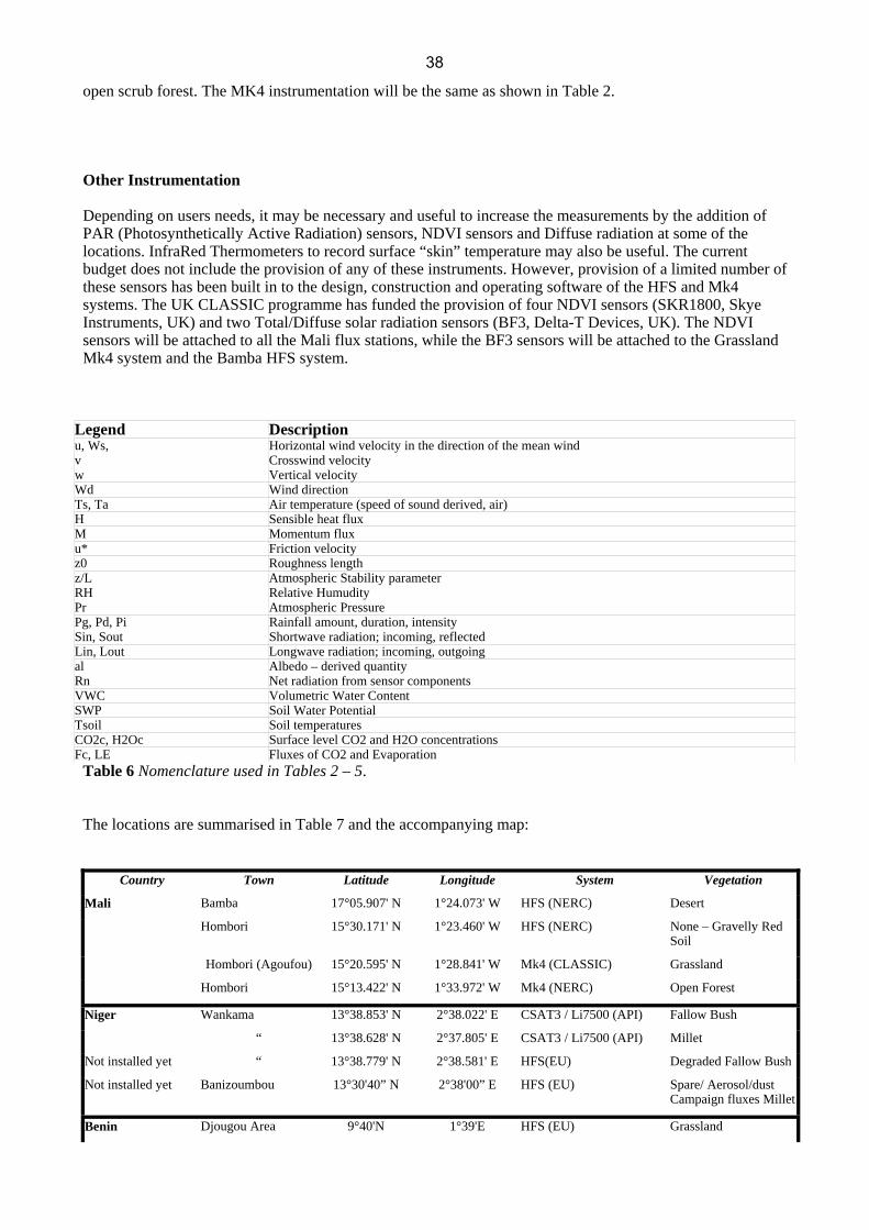
Table 6 Nomenclature used in Tables 2 – 5. The locations are summarised in Table 7 and the accompanying map:
Country Town Latitude Longitude System Vegetation
Mali Bamba 17°05.907' N 1°24.073' W HFS (NERC) Desert
Hombori 15°30.171' N 1°23.460' W HFS (NERC) None – Gravelly Red Soil
Hombori (Agoufou) 15°20.595' N 1°28.841' W Mk4 (CLASSIC) Grassland
Hombori 15°13.422' N 1°33.972' W Mk4 (NERC) Open Forest
Niger Wankama 13°38.853' N 2°38.022' E CSAT3 / Li7500 (API) Fallow Bush
“ 13°38.628' N 2°37.805' E CSAT3 / Li7500 (API) Millet
Not installed yet “ 13°38.779' N 2°38.581' E HFS(EU) Degraded Fallow Bush
Not installed yet Banizoumbou 13°30'40” N 2°38'00” E HFS (EU) Spare/ Aerosol/dust Campaign fluxes Millet
Benin Djougou Area 9°40'N 1°39'E HFS (EU) Grassland
38

Country Town Latitude Longitude System Vegetation
Not installed yet “ HFS (EU) Crops ?
Not installed yet “ API CO2/H2O system Forest ?
Nangantchori 9°38'N 1°44'E Solent/Li7500 Grassland
Djougou Area Wide Aperture Scintillometer
Composite
Parakou 9°06'160” N 1°56'37.6” E Modified Bowen Ratio Open Forest
Ghana Ejura 7°22'N 1°21'W Mk4 (NERC) Scrub Grassland
Table 7
d.) Priorities The HFS, Mk4 and API flux systems cited in this document have secured funding from NERC, the EU or French API. Priorities with regard to production of such systems is therefore not necessary. The additional instrumentation that can be attached to the HFS and Mk4 systems, i.e. Diffuse radiation, PAR, NDVI and IRT do not currently have funding within the EU or NERC funding of AMMA. The CLASSIC programme is providing funding for the inclusion of some of these measurements at one or more of the Mali supersite locations. In the case of extra but limited funding being found, priorities will need to be decided for the above instrumentation. With regard to risk, the following areas of concern may apply during the operation of the instrumentation in the EOP. Most of this information is particular to the AMMA-EU and AMMA-NERC equipment but many of the risks are pertinent to the operation of sophisticated instruments in west Africa. a) Delay in manufacture of HFS and Mk4 systems will ultimately impinge on the deployment date for
39

the systems. b) All equipment has allocated funds for airfreight and experience shows that this is the best option for the shipping of delicate items with low risk of damage and/or non-arrival. Equipment will be shipped allowing sufficient time for airfreight and customs release. c) The deployment of the systems has taken note of the current political and social stability of the countries within west Africa. Mali, Benin, Niger and Ghana have all been stable for several years and local knowledge has been sought at every opportunity to minimise this risk. d) The production of the HFS and Mk4 systems has taken note of the valuable nature of items in the systems, e.g. batteries, solar panels etc to the local economy and has taken precautions to prevent opportunist loss of these items. The deployment has tried to avoid the placement of systems in remote areas so that adequate local guarding of the valuable equipment can be organised. However, the requirements of the AMMA programme with regard to the latitudinal rainfall gradient has inevitably meant that some stations have been located in the north of Mali and southern Algeria. e) The risk of loss of data during the EOP has been addressed through a thorough design process of the instrumentation and logging equipment with regard to the climate, robustness of the sensors, the current general inexperience of the proposed operators and the length of the EOP. Thorough training of operators, provision of a complete spare HFS system and regular maintenance field visits by flux system experts during the EOP will help this situation but this risk cannot be eradicated and some loss of data should be expected from one or more of these continuously running systems during the EOP. The long-term unattended running of multiple eddy correlation flux systems in remote and harsh conditions has not been attempted before anywhere. With visits to field sites often being of the order of every 6 weeks, there is the very real possibility of up to 6 week gaps in the flux data. More frequent field visits will be effected during the periods around each SOP. 3. Deployment a.) Planning Lead times for manufacture and supply of sensors, together with the necessary time to construct and test the equipment, has meant that hardware for 3 Mk4 systems and 2 HFS systems have already been ordered and delivered (1 Feb 2005) from within the AMMA-NERC budget which came on-stream at the beginning of October 2004. This allowed some systems to be installed in Mali in April. Further deployment of the remaining AMMA-NERC systems will occur once the AMMA-EU systems have been constructed. To maintain compatibility within the training, data collection and subsequent analysis, CEH have liased directly with OSIL in the design and production of the AMMA-EU funded flux systems being produced by OSIL. As the systems, both in design and structure, are completely new, they will need a period of field testing prior to shipment to their final locations. A minimum period of one week should be set aside for this field testing. Such a course of action will also enable the operational instructions to be checked for anbiguity before the subsequent training of the field operatives. b.) Logistical considerations Installation and maintenance field visits to the flux station locations has to correspond with the presence of local field staff who can organise the transport and accomodation arrangements. It is imperative that the local knowledge of staff is used at all times with regard to local political activity and changing governmental bureauacracy and political situation. West African states have different policies with regard to visas, airfreight and customs control. Sufficient time needs to be allocated for the release of airfreighted equipment from customs control at the airport. The remote site at Bamba, Mali can only be serviced at 6 week periods in contrast to the remaining sites which will be serviced at 3 weekly periods -although operational considerations with regard to the Hombori site may require 6-week visits as well. This has necessitated some change to the data collection hardware and the controlling software. The longer time between servicing has attendant risks for the vulnerability of the equipment and loss of data, but modelled gap filling of lost data is easier at this site than more vegetated sites. Three of the AMMA-NERC flux systems and the CLASSIC-funded flux system were installed during 9-25
40
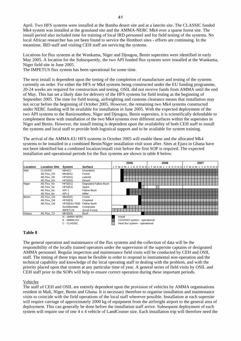
April. Two HFS systems were installed at the Bamba desert site and at a laterite site. The CLASSIC funded Mk4 system was installed at the grassland site and the AMMA-NERC Mk4 over a sparse forest site. The install period also included time for training of local IRD personnel and for field testing of the systems. No local African researcher has yet been found to service the Hombori sites - efforts are continuing. In the meantime, IRD staff and visiting CEH staff are servicing the systems. Locations for flux systems at the Wankama, Niger and Djougou, Benin supersites were identified in early May 2005. A location for the Subsequently, the two API funded flux systems were installed at the Wankama, Niger field site in June 2005. The IMPETUS flux system has been operational for some time. The next install is dependent upon the timing of the completion of manufacture and testing of the systems currently on order. For either the HFS or Mk4 systems being constructed under the EU funding programme, 20-24 weeks are required for construction and testing. OSIL did not receive funds from AMMA until the end of May. This has set a likely date for delivery of the HFS systems for field testing as the beginning of September 2005. The time for field testing, airfreighting and customs clearance means that installation may not occur before the beginning of October 2005. However, the remaining two Mk4 systems constructed under NERC funding will be available for installation in June 2005. With the expected deployment of the two API systems to the Banizoumbou, Niger and Djougou, Benin supersites, it is scientifically defendable to complement these with installation of the two Mk4 systems over different surfaces within the supersites in Niger and Benin. However, the install timing is dependent upon the availability of both CEH staff to install the systems and local staff to provide both logistical support and to be available for system training. The arrival of the AMMA-EU HFS systems in October 2005 will enable these and the allocated Mk4 systems to be installed in a combined Benin/Niger installation visit soon after. Sites at Ejura in Ghana have not been identified but a combined location/install visit before the first SOP is required. The expected installation and operational periods for the flux systems are shown in table 8 below.
Location Location Site System Surface J F M A M J J A S O N D J F M A M J J A S O N D J F M A M J J A S O N DMali CLASSIC Mk4(C) Grassland
AE.Flux_Gh Mk4(N1) ForestAE.Flux_Gh HFS(N1) LateriteAE.Flux_Gh HFS(N2) Desert
Niger AE.Flux_Nc HFS(E1) Degraded Fallow BushAE.Flux_Nc HFS(E2) SpareAE.Flux_Nc API-1 Fallow BushAE.Flux_Nc API-2 Millet
Benin AE.Flux_Od Mk4(N2) ForestAE.Flux_Od HFS(E3) CroplandAE.Flux_Od HFS(E4)+7500 Fallow Bush
Scintillometer CompositeIMPETUS Scrub Forest
Ghana AE.Flux_T2 Mk4(N3) BushN - AMMA-NERC InstallE - AMMA-EU CO2/H2O system - operationalC - CLASSIC Heat flux system - operational
2005 2006 2007
Table 8 The general operation and maintenance of the flux systems and the collection of data will be the responsibility of the locally trained operators under the supervision of the supersite captains or designated AMMA personnel. Regular inspection and maintenance field visits will be conducted by CEH and OSIL staff. The timing of these trips must be flexible in order to respond to instrumental non-operation and the technical capability and knowledge of the local operating staff in dealing with the problem, and with the priority placed upon that system at any particular time of year. A general series of field visits by OSIL and CEH staff prior to the SOPs will help to ensure correct operation during these important periods. Vehicles The staff of CEH and OSIL are entirely dependent upon the provision of vehicles by AMMA organisations resident in Mali, Niger, Benin and Ghana. It is necessary therefore to organise installation and maintenance visits to coincide with the field operations of the local staff wherever possible. Installation at each supersite will require carriage of approximately 2000 kg of equipment from the airfreight airport to the general area of deployment. This can generally be done before the installation staff arrive. Subsequent deployment of each system will require use of one 4 x 4 vehicle of LandCruiser size. Each installation trip will therefore need the
41

use of one 4 x 4 vehicle and driver for the duration of the installation trip i.e. of the order of 2 weeks. Subsequent maintenance visits (requiring one 4 x 4 vehicle + driver) will generally be of the order of 1 week. After installation, the regular 3 week (6 week at Bamba) visit to each flux station to inspect and download the data will require transportation to be arranged locally. The close proximity of the flux stations at each supersite means that all flux stations could be visited in a single day. Human Resources The installation of the flux stations will require a minimum of 2 people (for safety reasons) to build each station. Each station will be built consecutively. It would be more efficient if 3 people were involved in the assembly of each flux station. Regular inspection and downloading of the data from each station can be undertaken by 1 person. That same person will be responsible for the upload of data to supplied computer and subsequent copying of data to CD-ROM for posting to designated people within the AMMA community for quality control and databasing. Infrastructure The flux station installation and maintenance personnel will have to liase with and rely upon local staff for provision of invitation documents for visas, collection of airfreight from airport customs authorities, provision of vehicles and accomodation. The flux systems are solar panel battery powered and therefore mains power is not essential. Installation can be done without any specific office facilities but occasional use of a bench or part of an office for the use of laptops and inspection of sensors may be necessary. Four mains-powered Dell PC's have been purchased for the downloading of data and transfer to CD-ROM. These four PC's will require permanent bench space in an office at each of the supersites in Mali, Niger, Benin and Ghana for the whole of the EOP. There is no operational reason for these PC's to be linked into the local computer network 4. Partnership a) Field observations It is imperative, in any long-term measurement programme, to have dedicated staff to service the equipment and to collect the data. Each of the Super sites have very experienced staff who have worked in the region for many years. They have built up good relationships with the local people and have experience of the sophisticated equipment comprising the flux systems. WP 4.2.3 indicated that the “training of African scientists and technicians is a very important component of the activity of European teams involved in LOP-EOP” This is still the required aim; to employ and train local African researchers to operate and maintain the equipment, download and analyse the data and either write scientific papers or contribute to the writing of those papers. However, it has proved difficult to identify suitable local staff to maintain the novel and instrumentally sophisticated HFS, Mk4 and similar flux systems and currently there is no general solution within budget. The priority for CEH and Ocean Scientific International Ltd (OSIL) has been to build and deploy these systems before the first SOP which has left little time to organise structured and comprehensive training before the systems were installed. More effort needs to be applied to find suitable African technicians and to train them sufficiently to be able to routinely run the flux systems A local technician employed by the Institut d'Economie Rurale (IER) at the Bamba ( Mali) site has been recruited. The remoteness of this site and the unavoidable short training programme given to him during the installation of the flux system has meant that currently data is sporadic from this site. The other sites in Mali are being operated by staff of IRD from Bamako (16 hours travel from Hombori) which is expensive and deflects IRD staff from their normal duties. The situation in Niger and Benin, where field sites are no more than 1 hour from the main supersite centre, will be easier to organise and maintain. Dialogue is continuing with the Site Captains at Niamey and Djougou to identify local African technicians willing to maintain the flux systems. At the Mali Supersite around Hombori, Dr Eric Mougin (Supersite Captain) and the staff of CESBIO will be
42

conducting intensive vegetation surveys throughout the EOP and will provide the staff to service the flux systems at Hombori on a 3 week cycle. Currently, this is being performed by Dr Franck Timouk but it is highly desirable to find an African researcher to take on this responsibility. The northern site at Bamba is being serviced by M. Lamine ???, an employee of IER. This site, due to its remote location, will only be serviced every 6 weeks. A strong linkage to IRD is important for transport and other logistics. At the Banizoumbou, Niger supersite, Dr Luc Descroix (supersite Captain), Dr Bernard Cappalaere and Dr Jean-Loius Rijot have project interest in the flux data and will be involved with the collection and use of the flux field data. At the Djougou, Benin supersite, Drs Sylvie Galle and Christophe Peugeot (supersite Captains) will be requested to assume overall responsibility for the supervision of the maintenance of the flux systems and the collection of the data. At the Ghana GLOWA site, Mr B.O. Antwi as Manager of the Ejura site, will be requested to provide logistical support and Dr Nick van der Geisen will provide the collaborative link for the surface flux work. (THIS STILL HAS TO BE NEGOTIATED AND AGREED WITH GLOWA PERSONNEL) b)Training programme Training is an important component of the AMMA programme and OSIL UK and CEH Wallingford will provide suitable training in understanding the design, technical specification and operation of the flux systems. Of equal importance when operating flux systems is an appreciation of the micrometeorology of the local region around the flux system. A short and concise training package will be created that provides field operatives with the background knowledge to appreciate the operation of the flux systems and the micrometeorology of the flux station site. Training will be given locally on the operation of the measurement systems but funding is being sought to allow a Workshop to be convened in west Africa that will provide a much wider appreciation of the measurement techniques, operation and use of the resultant data. Close collaboration with ST4 on this latter topic will help in identifying suitable candidates, training locations, possible funding and the workshop organisational aspects. 5. Organisation of the TT a) Leaders, core group, membership Drs Colin Lloyd and Chris Taylor will jointly lead the TT to provide an amalgam of observation and modelling. The length of time that Lloyd will spend in the field also requires an accessible node for communication when he is absent.
Surname first name email address Function
TT Leaders Lloyd Colin [email protected] Surface Fluxes
Taylor Chris [email protected] Land-Atmosphere Interactions
Core Group Members Beljaars Anton [email protected] Numerical Weather Prediction
Boulain Nicolas [email protected]
Cappelaere Bernard [email protected] TT4 Niger & surface interactions
Cohard Jean-Martial [email protected] Scintillometry
Galle Sylvie [email protected] TT5 Benin Supersite Captain
Fink Andreas [email protected] Benin Flux measurements
Laurent Jean-Paul [email protected]
Marticorena Béatrice [email protected] TT2b EOP/LOP Aerosols
Peugeot Christophe [email protected] TT5 Benin Supersite Captain
Rajot Jean-Louis [email protected] Dust deposition, Aerosols
Serça Dominique [email protected] Benin & Aircraft measurements
43
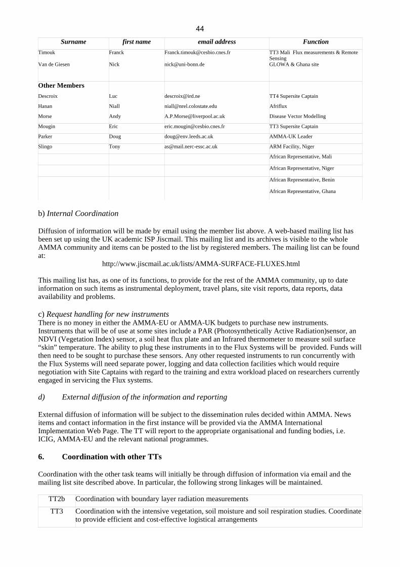
Surname first name email address Function Timouk Franck [email protected] TT3 Mali Flux measurements & Remote
Sensing Van de Giesen Nick [email protected] GLOWA & Ghana site
Other Members Descroix Luc [email protected] TT4 Supersite Captain
Hanan Niall [email protected] Afriflux
Morse Andy [email protected] Disease Vector Modelling
Mougin Eric [email protected] TT3 Supersite Captain
Parker Doug [email protected] AMMA-UK Leader
Slingo Tony [email protected] ARM Facility, Niger
African Representative, Mali
African Representative, Niger
African Representative, Benin
African Representative, Ghana
b) Internal Coordination Diffusion of information will be made by email using the member list above. A web-based mailing list has been set up using the UK academic ISP Jiscmail. This mailing list and its archives is visible to the whole AMMA community and items can be posted to the list by registered members. The mailing list can be found at:
http://www.jiscmail.ac.uk/lists/AMMA-SURFACE-FLUXES.html This mailing list has, as one of its functions, to provide for the rest of the AMMA community, up to date information on such items as instrumental deployment, travel plans, site visit reports, data reports, data availability and problems. c) Request handling for new instruments There is no money in either the AMMA-EU or AMMA-UK budgets to purchase new instruments. Instruments that will be of use at some sites include a PAR (Photosynthetically Active Radiation)sensor, an NDVI (Vegetation Index) sensor, a soil heat flux plate and an Infrared thermometer to measure soil surface “skin” temperature. The ability to plug these instruments in to the Flux Systems will be provided. Funds will then need to be sought to purchase these sensors. Any other requested instruments to run concurrently with the Flux Systems will need separate power, logging and data collection facilities which would require negotiation with Site Captains with regard to the training and extra workload placed on researchers currently engaged in servicing the Flux systems. d) External diffusion of the information and reporting External diffusion of information will be subject to the dissemination rules decided within AMMA. News items and contact information in the first instance will be provided via the AMMA International Implementation Web Page. The TT will report to the appropriate organisational and funding bodies, i.e. ICIG, AMMA-EU and the relevant national programmes. 6. Coordination with other TTs Coordination with the other task teams will initially be through diffusion of information via email and the mailing list site described above. In particular, the following strong linkages will be maintained.
TT2b Coordination with boundary layer radiation measurements
TT3 Coordination with the intensive vegetation, soil moisture and soil respiration studies. Coordinate to provide efficient and cost-effective logistical arrangements
44

TT2b Coordination with boundary layer radiation measurements
TT4 Coordination with the catchment and sub-catchment hydrological studies. Coordinate to provide efficient and cost-effective logistical arrangements
TT5 Coordination with the ongoing hydrological and vegetation studies. Coordinate to provide efficient and cost-effective logistical arrangements
TT7 Coordination and comparison with the larger scale radiation, sensible and latent heat fluxes.
TT8 Coordination and comparison with the mesoscale modelling aspects of the surface flux regime. Coordination with the experimental aspects of this TT.
7. Ancillary information: reference, logistic forms, site document See appendices: Instrumentation forms, etc to be added.
45

Task Team 2b – Aerosol Monitoring BM May 2005
AMMA Task Team 2b
EOP/LOP Aerosols Monitoring and radiation
01 July 2005
Preliminary draft
46
Task Team 2b – Aerosol Monitoring BM May 2005
1. Scientific justification and objectives
1.1 Context
West Africa is the world's largest source of biomass burning aerosols and mineral dust.
Satellite sensors consistently indicate that these aerosol plumes are the most widespread, persistent
and dense found on Earth. The role of dust and carbonaceous aerosols effect on the climate change
is one of the large incertitude pointed out by IPCC 2001. They directly impact the radiative budget and
the microphysics of clouds, and their proximity to tropical deep convection gives them the potential to
be exported over great distances. Mineral dust exported from western Africa over the subtropical
Atlantic Ocean also represents a significant input of nutrient (mainly Fe) for remote marine
ecosystems. The seasonal cycle of dust and smoke are directly linked to meteorological processes in
the monsoon.
For example, a clear correlation was established between drought occurrences and increase
in desert dust load in the atmosphere not only in the Sahel (N’Tchayi et al. 1994) but also far from
African sources in the transport zone of Caribbean islands (Prospero and Lamb, 2003). These two
simultaneous increases (dust haze in the Sahel, concentration of long range transported dust) have
been interpreted as being due to an increase of the local dust emissions in the Sahel during the
drought periods. This increase is attributed to the appearance of additional Sahelian sources in
regions where lowest rainfall has lead to an observed decrease of the vegetation cover rate (Tucker et
al., 1991). The contribution of the Sahelian belt to the mineral dust emission from North Africa has
been further questioned based on numerical simulations of the mineral dust cycle performed with a
global transport model (Tegen and Fung, 1995), showing that a correct simulation of dust
concentrations over the Northern Tropical Atlantic Ocean and of the seasonal pattern of the Saharan
plume requires the inclusion of Sahelian sources with a contribution of 30-50 % of the global dust
emissions. These Sahelian emissions were attributed to regions affected by climatic changes and/or
anthropogenic disturbance. From these results, some authors concluded that the Sahel was the major
source of mineral dust in North Africa (Nicholson, 2000).
Similarly, the atmospheric content of biomass burning aerosol is expected to be connected to
El Niño events. Indeed during years of regional drought, such as those in southern Africa associated
with El Niño events, the area burned decreases by about half (Justice et al., 1996). It is believed that
this is caused principally by a decrease in fuel availability. Since gas and aerosol emissions from
biomass directly depend on the burned areas, the relationships between the atmospheric content of
carbonaceous aerosols atmospheric content and climatic indicators of the intensity of El Niño events
intensity are investigated (Liousse et al, forthcoming).
Because the aerosol emissions and transport are controlled by climatic parameters (directly or
indirectly through vegetation variations), a long term monitoring of the aerosol atmospheric content at
the regional scale is required to elucidate these complex relationships.
In last decades, remote sensing offers the opportunity to document on a large spatial and
temporal scale the aerosol load over Western Africa. However the retrieval of the aerosol content over
land surfaces is much more complex than over ocean so that, to date, the available information is only
47

Task Team 2b – Aerosol Monitoring BM May 2005
semi-quantitative (Aerosol Index TOMS; Infrared Different Dust Index). New sensors, such as MODIS,
are starting being used to fill this important gap. In this respect, ground based monitoring is absolutely
essential (1) to document properly the annual and inter annual variability of the atmospheric aerosols
content over the African continent in order to understand the processes that controls this variability at
the various time-scales, (2) to document their optical properties in order to better constrain their
radiative impact. Such a monitoring was initiated in western Africa in the 90’s in particular through two
networks: PHOTONS/AERONET and IDAF.
PHOTONS is a part of the international sunphotometer Aerosol Robotic Network (AERONET).
This network was developed to provide aerosol information from ground-based measurements all over
the world. It provides globally distributed near-real-time observations of the aerosol spectral optical
thickness and sky radiance as well as derived parameters such as particle size distributions, single-
scattering albedo and complex refractive index. The AERONET data have been widely used to
establish climatology of aerosol properties (Holben et al., 2001; Dubovik et al., 2000), to validate
satellite retrieval of aerosols products or global or regional simulations of the aerosol atmospheric
content. To date, more than 10 years of worldwide distributed data from the AERONET network of
ground-based radiometers are available. They are suited to reliably and continuously derive the
detailed aerosol optical properties in key locations. From 1994, 14 stations have been installed in
western Africa, with different period and duration of observations. Ten stations are nowadays
operational. PHOTONS/AERONET is a French National Observatory for Environmental Research
dedicated to aerosol observation supported by the French national agencies for Space Studies
(Centre National d’Etudes Spatiales, CNES) and for Earth and Universe studies (Institut National des
Sciences de l’Univers, INSU).
The IDAF (IGAC/DEBITS/Africa) network is the African component of the international
program DEBITS (International Global Atmospheric Chemistry / Deposition of Important
Biogeochemically Trace Species) devoted to the monitoring of the gas and aerosol concentrations in
the atmosphere and in wet and dry atmospheric deposition. It was created in 1994 and is, like
PHOTONS, a French National Observatory for Environmental Research (ORE). The 5 IDAF ORES
stations are located in the 3 main African ecosystems: dry savannah, wet savannah and equatorial
forest. The main objectives of the IDAF network are to analyse the evolution trends of the chemical
composition of aerosol, precipitations and gas as a function of the main seasonal emission sources.
This allows to identify the physical and chemical processes controlling the wet and dry deposition
processes and finally, to improve the parameterisation of these processes in atmospheric models.
In addition to these pre-existing networks, a “Sahelian Dust Transect” will be equipped in
order to document specifically the mineral dust content and its transport toward the North Atlantic
Ocean. One of the specificity of the mineral dust originating from the Sahara and Sahelian regions is
that it can be transported at different altitudes. Typically, during summer, mineral dust from the Sahara
is transported across the North Atlantic Ocean above the MBL within the Saharan Air Layer (SAL).
This is supported by various lidar measurements offshore western Africa (Karyampoudi et al., 1999;
Immler and Schrems, 2003), and it becomes evident when looking at the combination of surface
concentration and the column-integrated aerosol optical depth of mineral dust measured over the Cap
Verde Islands (figure 1). Recently, intensive field campaigns including aircraft measurements
48

Task Team 2b – Aerosol Monitoring BM May 2005
(CLAIRE-LBA, PRIDE) showed that long range transport of Saharan dust can also take place within
the surface layer (Formenti et al., 2001; Reid et al., 2002) . The altitude of the dust transport layer,
and in particular the position of the dust layers relative to clouds can significantly change the dust
radiative impact. Different altitude transport patterns will also induce different deposition patterns and
thus impact significantly the regional dust budget. To take into account this variability, three stations
have been selected along the main dust transport pathway, for which the surface concentration, the
vertically integrated dust amount, the vertical distribution and the wet and dry deposition will be
monitored during the EOP period.
Dust surface concentration (Chiapello , 1995)
Averaged aerosol optical depth 1993-2002 (data from the AERONET network)
1.2 Scientific questions related to AMMA-EU WP 1.2.1 Main related WP.
The main objective of these ground based stations is to provide observations that will be used
to investigate the variability of the regional distribution of aerosol over western Africa, at various time
scale, from a few days to a decade. They represent additional constrain for the assessment of their
long range transport and of their impact. It is thus of particular importance for the WP 2.4 “Aerosol and Chemical processes in the Atmosphere ”. The questions raised from this integrative WP that
will benefit from the data obtained in this TT are listed below :
WP 2.4.1 Aerosol radiative properties -What is the regional and vertical distribution of the aerosols over WA, and what is its dependence on
the seasonal cycle of the monsoon?
- How do the physical-chemical properties of mineral dust depend on source region (Sahara/Sahel)?
- How does the aerosol vertical layering control its radiative impact?
WP 2.4.2 Gas and particle phase chemistry - How much secondary organic aerosol is produced from anthropogenic and biogenic species in the
WAM region?
- What is the potential for new particle production in the free troposphere from biogenic and
anthropogenic gas-phase precursors?
0
0.1
0.2
0.3
0.4
0.5
0.6
0.7
JAN FEB MAR APR MAY JUN JUL AUG SEP OCT NOV DECMoyenne 1993-2002
AOD
@ 5
00nm
SOP1
SOP2
SOP0
49

Task Team 2b – Aerosol Monitoring BM May 2005
WP 2.4.3 Surface processes - What is the magnitude of surface emissions of aerosols and trace gases from WA and how do these
emissions vary at the seasonal and interannual timescales in relation with the variability of the
monsoon system?
-What are the respective contributions of the climatic and anthropogenic factors in the variability of the
aerosol (mineral dust and biomass burning aerosols) and trace gas emissions?
- What are the regulating factors of the wet and dry deposition of aerosols?
- Is the Sahelian belt a net source of mineral dust or a deposition area for Saharan dust ?
WP 2.4.3 Effect of convection on regional chemical and aerosol budgets - What is the role of convective physical processes vertical transport, mixing, deposition on the budget
of major oxidants and aerosols in the free troposphere over West Africa ?
- How do deep convective processes influence the distributions of chemical constituents in the TTL
compared to other transport processes ?
- What is the role of photochemical reactivity and heterogeneous chemistry on air masses transported
over West Africa from large-scale convective outflow ?
1.2.2 Other related WP.
The assessment of the aerosol properties and regional distribution are required to achieve the
objectives of several other WP concerned by the impacts of aerosol, and in particular the impact of the
aerosol radiative effect on dynamic processes at various spatial and time scale. The main questions of
the different WP in terms of aerosol impact are listed below
- determination of the impact of the WAM emissions on global oxidant and aerosol budgets, the
oxiding capacity and global radiative forcing (WP 1.1.2) - assessment of the variations in sensible heat flux forced by both atmospheric composition (aerosol
content) and soil moisture (WP 1.3.2) - quantification of the effect of the radiative forcing due to aerosol and humidity patterns in the clear air
and understanding of the interaction between convective and radiative processes interacting with the
dynamics of weather systems developing along the the Sahel (WP 2.1), and in particular assessment
of the role of the Saharan air layer on the in AEW dynamics over land and in the development and
intensity change of tropical cyclones (WP 2.1.1).
50

Task Team 2b – Aerosol Monitoring BM May 2005
1.2.3 TT2b-related Objectives from the PIAF.
As listed below, some of the projects from the PIAF could also benefit from the measurements
and theoretical studies developed in this TT. It must be noted that some of the responsible of these
project are already involved in the experimental deployment of the TT2b stations.
Name Affiliation /
country Research area Project proposal
AKPO Aristide Bénin Aérosols, convection, Physique de l'Atmosphère
Impacts des aérosols désertiques sur la Mousson Africaine
SILVA Ana Maria Portugal Atmospheric Physics The Health effects of aerosols at Cabo Verde
JEANNE Isabelle CERMES Conception analyses SIG Télédétection Terrain
Méningites et climat. Paludisme et climat : CLIMPAL-Niger
KOUADIO Georges Côte d'Ivoire Dynamique de l'Atmosphère,Mesure des flux et paramétrisation
Quantification et modélisation des émissions d'oxydes d'azote par les agrosystèmes fertilisés et impact sur la chimie de l'air en Afrique de l'Ouest
N'GORAN Yao Côte d'Ivoire Rayonnement, Gisement Etude et exploitation du gisement solaire Ouest Africain à partir de l'imagerie satellitaire(GISOA-SAT)
YOBOUE Véronique Côte d'Ivoire Bilan de l'azote Etude de la pollution atmosphérique dans les capitales africaines en Afrique de l'Ouest et chimie des précipitations en zone de savane humide
SEYDOU SANDA Ibrah
Niger Aérosols-convection, Variabilité atmosphérique
Aérosols et convection
Zibo Garba Niger Aérosols, Ensablement, Paléoclimatique, SIG Télédétection
Mise en place d'un observatoire "proximal" en bordure du Sahara pour la surveillance et l'analyse des processus éoliens et de leurs impacts (Nguigmi, Mainé-Soroa et Gouré au Niger Oriental, Bassin du Lac Tchad)
CAMARA Moctar Sénégal Physique de l'Atmosphère
Perturbations atmosphériques en Afrique de l'Ouest et activité cyclonique sur l'Atlantique
GAYE Amadou Thierno
Sénégal Aérosols-Pollution Aérosols-chimie-processus radiatifs-pollution
51

Task Team 2b – Aerosol Monitoring BM May 2005
2. Observing strategy
2.1 Main instrumentation
2.1.1 Observation period
Both the AERONET/PHOTON and the IDAF network are already operational and will provide
measurements for the whole LOP period (10 years). The Sahelian dust transect will operate during
the EOP (3 years) with a possible extension to 5 years, depending of experimental conditions and
financial support. The stations are not yet fully equipped but will be operational by the end of 2005.
2.1.2 Deployment.
Despite the constraints imposed by their status, both AERONET/PHOTON and IDAF have
adapted the deployment of their stations to the need expressed by the various WPs of AMMA. The
Sahelian dust transect has been deployed specifically for the AMMA project. The location of the
stations was defined in order to (1) be north of the main biomass burning areas; (2) follow the main
summertime transport pattern of mineral dust; (3) be at equal distances between each other; (4) as a
function of logistic constrains. Finally, political considerations have been taken into account in the
proposed deployment.
Table 1 summarizes the name, location and status of the different stations that are also
located on figure 2.
Station IDAF AERONET Dust
Transect SOLAS
Agoufou (15.34N, 1.48W), Mali x Banizoumbou (13.54N,2.66E), Niger x x x Capo Verde (16.73N, 22.93W), x x Dahkla (23.71N,15.95W); Morocco x Dakar (14.39N,16.96W), Senegal x x Djougou (9.66’N, 1.91E); Benin x x IER-Cinzana (13.28N,5.93W), Mali x x Illorin (8.32N, 4.34E), Nigeria x Lamto (6N, 5W )Ivory Coast) x Ouagadougou (12.20N, 1.40W ) Burkina Faso x Zoétélé (3.16N,11.96E ) Cameroon x
Table 1 : Name and coordinates of the ground based stations involved in TT2b and related networks.
As illustrated on figure 2, the AERONET/PHOTONS stations covers two main axes : a longitudinal
axe from Niamey to Dakar and an almost latitudinal axe from Agoufou to Illorin. During the SOP period
these axes will be extended further East toward the Chad frontier (Maine Soroa, Niger) and further
North (Tamanrasset, Algeria).
52

Task Team 2b – Aerosol Monitoring BM May 2005
The IDAF stations have been deployed in order to represent the 3 main African ecosystems.
Agoufou (Mali) and Banizoumbou (Niger) are located in the dry savannah, Djougou (Benin) and Lamto
(Ivory Coast) in the wet savannah and Zoétélé in the equatorial forest.
The Sahelian dust transect station have been deployed along the main direction of transport of
Saharan and sahelian dust, i.e the longitudinal AERONET axe from Niamey to Dakar. The three
stations are AERONET stations.
A SOLAS observatory should be installed in the Cap Verde Islands, i.e along the same
longitudinal axes (See part 2.2.2) (to be confirmed and precised).
Figure 2 : Location of the ground based TT2b stations; the red AERONET symbols correspond to the EOP period deployment, the orange symbols correspond to instruments that will be deployed during SOP period only. The SOLAS observatory is described in part 2.2.2.
solas solas
AERONET
IDAF Dust transect
solas solas Solas Obs.
53
Task Team 2b – Aerosol Monitoring BM May 2005
2.1.3 Instrumentation
Tables 2, 3, 4 summarize the instruments deployed in the different sites and the parameters
that will be retrieved from these instruments for each network. A complete description of the
instrumentation can be found in the instruments forms (IDAF related froms : LF26/CL.Depot_RW;
EF32/AE_Aerosol_Lam; Sahelian dust transect related forms: EF30/AE_DUST_ST).
2.1.3.1 AERONET
The sunphotometer (CIMEL) used in AERONET is an automatic instrument providing direct
sun and diffuse radiation measurements under clear sky conditions at a variable frequency throughout
the day. Data from all AERONET sites are sent hourly from each fieldsite to the Wallops Receiving
Center via transmissions to satellite (GOES, METEOSAT) using VITEL transmitters. These raw data
are then transferred hourly from the Wallops receiving station to the Goddard Facility for treatment.
The standardized network procedures (Holben et al., 1998; Smirnov et al., 2000) of instrument
maintenance, calibration, cloud screening, and data processing allow for quantitative comparison of
the aerosol data obtained in different times and locations. The inversion algorithm (Dubovik and King
2000) provides improved aerosol retrievals by fitting the entire measured field of radiances (sun
radiance and the angular distribution of sky radiances at 0.44, 0.67, 0.87, and 1.02 µm) to a radiative
transfer model.
The retrieved geophysical parameters and inversion products are available in almost real time
on the AERONET web site (http://aeronet.gsfc.nasa.gov/).
AERONET/PHOTONS Measurement Geophysical Parameter
Sun radiation extinction at several wavelengths Angular distribution of sky radiance
- Aerosol Optical Thickness - Angström coefficient
- Size distribution - Single scattering albedo
Table 2 : Measurements and retrieved parameter from the AERONET/PHOTON network.
2.1.3.2 IDAF Basically, the measurements performed at the IDAF stations are weekly aerosol sampling for
particle sizes smaller than 10 µm (PM10) and 2.5 µm (PM2.5) diameter, and wet deposition collected
for each rain. Mass weighing and chemical speciation are performed for both aerosol and rain
samples. The sampling and analytical procedures respond to the international standards defined by
the World Meteorological Organization (WMO) and Global Atmospheric Watch (GAW). Additionally,
54

Task Team 2b – Aerosol Monitoring BM May 2005
the black and organic carbon fraction in the PM2.5 is determined. These protocols are described on
the IDAF webpage : http://medias.obs-mip.fr.idaf/.
The data are collected and transmitted to this web site and are available to the AMMA program
IDAF
Measurement Geophysical Parameter Aerosol sampling/chemical analyses Rain collector Gas phase sampling/analysis
- Atmospheric mass concentration at the ground level for PM2.5 and PM10
- Chemical composition (mineral and organic soluble fraction, carbonaceous fraction, trace metal)
- Particulate carbon (concentration, Black carbon and organic carbon)
- Wet deposition - Rain chemical ionic composition, pH,
conductivity - Atmospheric concentration (SO2, NO2,
NH3, HNO3, O3)
Table 3a : Measurements and retrieved parameter from the IDAF network. Additional measurements will be performed in the Djougou station during the EOP period in
order to further investigate the aerosol optical properties. Djougou is also an AERONET stations thus
all the microphysical parameters derived from the photometric measurements will also be available.
DJOUGOU IDAF station
Measurement Geophysical Parameter Aerosol physical and optical properties Meteorological parameters Gas phase sampling/analysis
- Particle number concentration, size distribution, absorption and extinction coefficient;
- To be described - Atmospheric concentration (NOx, CO,
CO2)
Table 3b : Additional measurements for the Djougou IDAF station.
55

Task Team 2b – Aerosol Monitoring BM May 2005
2.1.3.3 Sahelian dust transect
The objective of this sahelian dust transect is to provide a set of aerosol measurements
allowing to assess the mineral dust budget at the regional scale. It thus includes measurements of the
aerosol concentration at surface level, the aerosol vertical distribution, the wet and dry deposition flux,
and the column-integrated aerosol amount and properties. The three stations are AERONET stations
thus all the microphysical parameters derived from the photometric measurements will also be
available. Banizoumbou is also an IDAF station, so additional information on the chemical composition
of rain and aerosols will be available.
The aerosol concentration is measured by an automatic instrument (TEOM) with a frequency
of 15 min. Wet deposition is collected for each rain event. For dry deposition the sampling period is
conditioned by the minimum total collected mass that can be measured. The objective is a weekly
sampling but longer sampling periods are expected during winter and shorter period during the spring
where surface concentration and dust event frequency are the highest. Lidar measurements will be
performed at selected times throughout the day and / or night (depending on station), the number of
measurements should be of the order of 4/day but it still need to be precisely defined depending on
maintenance costs and available funding. The data are collected locally and will be made available as
part of the AMMA database.
Sahelian Dust Transect
Instrument-Measurement Geophysical Parameter Aerosol sampling Rain collector Passive collector Microlidar (MPL)/Extinction profile
- Atmospheric mass concentration for
PM10
- Wet deposition
- Dry deposition (mass and size distribution)
- Aerosol vertical distribution, aerosol identification
Table 4a : Measurements and retrieved parameter from the Sahelian Dust transect.
Ideally, dust emission fluxes should also be monitored continuously over the EOP period.
However, the vertical emission flux measurement and detailed aerosol characterization (composition,
optical properties) cannot be routinely measured due to the complexity of the experimental techniques
and the cost (in time and money) required by the chemical analysis. Such measurements will be
performed during SOPs only at the Banizoumbou super-site (SF-10 instrument). To get information on
the variability of the dust emission fluxes, the “erosion” flux (horizontal flux) will be monitored at
Banzoumbou over an agricultural field. The site will also be equipped with a Heat flux station (TT2a)
56
Task Team 2b – Aerosol Monitoring BM May 2005
that will provide information on the local wind shear stress u* (controlling the intensity of the erosion
fluxes) and roughness length Z0 (that strongly influence the erosion threshold). The vegetation cover
will also be monitored in order to determine ist influence on the erosion fluxes.
Sahelian Dust Transect Instrument-Measurement Geophysical Parameter
Micro-mast equipped with sand catchers Saltiphone Vegetation cover
- Vertical profile of eroded mass
- Erosion threshold; erosion periods
- Surface cover rate, mean height
Table 4b : Additional measurements to monitor the erosion fluxes at Banizoumbou.
2.2 Related instrumentation
2.2.1 Related SOP instrumentation
The TT2b stations include the three super-sites for aerosol measurements (Dakar,
Banizoumbou, Djougou) and radiative budget measurements (ARM mobile facility in Niamey airport
and field measurements in Banizoumbou) that will be deployed for the SOP period. These super sites
are mainly deployed to describe the physical-chemical and optical properties of the atmospheric
aerosols and to determined experimentally the aerosol radiative effect. The equipment of these
stations is described in the TT7 and TT8 strategic planning and related instrumentation form.
2.2.2 Related EOP instrumentation
2.2.2.1 Heat flux and radiative fluxes stations
The TT2b stations include the stations devoted to EOP Heat fluxes measurements (TT2a :
Agoufou, Banizoumbou, Djougou). Radiative fluxes measurements will be deployed at these three
sites but also in Ghana (to be précised)
2.2.2.2 SOLAS Observatory
Because of the biogeochemical impact of mineral dust, continuous monitoring of trace gases and
aerosols should deployed from 2006 to 2009 in the framework of the SOLAS program. This SOLAS
observatory should be supported by the UK and German national SOLAS program (to be confirmed)
57

Task Team 2b – Aerosol Monitoring BM May 2005
The SOLAS observatory should provide continuous measurements from 2006 to 2009, i.e., a
temporal scale comparable to the EOP period.
SOLAS Observatory Instrument-Measurement Geophysical Parameter
Aerosol sampling Gas phase sampling/analyses Meteorological station Radiation measurements
- To be defined
- Atmospheric concentration (O3,CO, NO,
NO2, NMHCs, OVOCs, DMS, NH3, HNO3, long lived and reactive halocarbon, stable gas)
- To be defined
- To be defined
3. Modelling and satellite observations
AERONET measurements have been widely used to test and validate aerosol satellite products
and simulations of aerosol models. Additional information on the aerosol surface concentrations,
chemical composition and vertical distribution will help to further constrain models and satellite
retrievals. The distance between the stations favours the use of the acquired data set both for global
and regional simulations. The lidar measurements will be particularly useful for the CALIPSO
validation. In turn, satellite aerosol products will provide a way to interpolate the local ground based
measurements.
These measurements are particularly required to evaluate whether 3D aerosol models are able to
reproduce the long-term variability of the aerosol atmospheric content. This implies that the
relationships between aerosol emissions and deposition and the climatic conditions have been
understood and correctly described in such simulations. These measurements will mainly benefit to
test the simulations performed over long periods (CHIMERE-Dust) and in particular to test the
simulations of the aerosols cycles in climatic models (LMDz; REG-CM…).
58

Task Team 2b – Aerosol Monitoring BM May 2005
4. Partnership
All the TT2b stations are maintained through collaboration with local institutions, for the
maintenance required by a continuous monitoring, for specific manual manipulation (i.e., wet and dry
deposition collection) and for specific failures. Local people involved in the measurements are formed
by European scientists either on the sites or in the European laboratories.
It must also be noted that African partners involved in the deployment of these stations have
proposed scientific project in the PIAF. Further efforts are thus required to develop scientific
cooperation with the already involved team and to favour new implication.
5. Organisation of the TT. 5.1 Leaders, core group, membership
Coordinators: Béatrice Marticorena (France) , Francesco Cairo (Italy) Core group: To be confirmed C. Liousse (France), J.L Rajot (France/Niger),, P. Gouloub (France), V. Yoboué (Ivory Cost). Representation: To be confirmed Representatives of the TT3, 4 and 5 : F. Lavenu, JL. Rajot, C. Liousse. TT2a: C. Lloyd TT7: Ellie Highwood TT8: P. Formenti Other members : To be confirmed … UK related proposals : Hugh Coe ; Martin Todd, Richard Washington SOLAS observatory : Allistair Lewis; Konrad Müller, Martin Heimann. ARM station : Tony Slingo; Ron Brown Cruises : Erica Key Modelling groups : Gé Verver, B. Vogel Satellite groups : I. Chiapello, J.F Léon AERONET : B. Chatenet IDAF : C. Galy-Lacaux + local scientist Local institutions: to be defined 5.2 Internal coordination
The implementation of the EOP/LOP observations will be coordinated within the existing EU
project structure, it will be the work of this TT to ensure that the operations of these groups are
complementary.
5.3 How are requests for new instruments handled?
These are discussed by the whole TT2b group and approved by Core Group. However, the
deployment of any additional instrumentation obtained through the national label (ORE) will be
discussed regarded the national objectives.
59
Task Team 2b – Aerosol Monitoring BM May 2005
5.4 External diffusion of the information and reporting
External diffusion of the information will be insured through the AMMA international implementation web page. The TT will report to the ICIG, AMMA-EU and national programs. 6. Coordination with other TTs. TT2b Coordination with Heat and radiative fluxes measurements TT3 Coordinating complementary instruments (radiation, fluxes, vegetation, etc ..);
Optimizing logistical efforts. TT4 Coordinating complementary instruments (radiation, fluxes, vegetation, etc ..);
Optimizing logistical efforts. TT5 Coordinating complementary instruments (radiation, fluxes, vegetation, etc ..);
Optimizing logistical efforts. TT7 Coordination of measurements with SOP, intercomparison of aerosol
measurements, possible increase of the sampling frequency. TT8 Coordination of measurements with SOP, intercomparison of aerosol
measurements, possible increase of the sampling frequency. 7. Ancillary information: reference, logistic forms, site document. See appendices = Instrumentation forms to be added ?
60

Task Team 2b – Aerosol Monitoring BM May 2005
62
AMMA Implementation Plan TT3 Gourma EOP Studies
TT3 - EOP integrative studies on the Gourma meso-scale site (Mali)
Updated May 8, 2005
11.. Scientific justification and objectives : The aim of this document is to present the observing strategy in the Gourma meso-scale site in Mali, with respect to the objectives of the AMMA project detailed in the AMMA-IP and AMMA-API proposals. Particularly, this document gives the list of the instruments, presents the schedule of their deployment and addresses the associated logistic issues. In Mali, EOP focuses on quantification of water, CO2 and energy fluxes that occur between the surface and the atmosphere. Among the surface processes under consideration, emphasis is put on evapotranspiration which is the most important process coupling the physical, biological and hydrological processes occurring at the continental surface. It is also the term of the water budget responsible of the surface retroaction to the atmosphere, since evapotranspired water then enters the regional atmospheric circulation. It is also the most poorly measured and understood term of the water budget. The main scientific objective is therefore to better understand, model and predict temporal and spatial variations of evapotranspiration in a bottom up approach integrating all the physical, biological and hydrological processes involved.
Understanding, modelling and predicting plant phenology (i.e. the seasonal cycle of LAI and biomass) is the key issue to correctly predict the evapotranspiration cycle along the year. Most process studies focus on integrating the numerous ecological processes (carbon assimilation, water uptake and release, vegetation growth and decay, coupled C/H2O/N cycles,…) responsible for the phenological cycle. Moreover, water transpiration is closely linked to CO2 assimilation through the stomatal control by plants. This coupling is simulated in most current SVAT models. The water extraction strategy and the phenological cycle of plants are used to define major plant functional groups.
The question of the long term dynamics of sahelian vegetation is also addressed since the Gourma vegetation sites have been monitoring for about 20 years. The vegetation monitoring sites are part of the AMMA-CATCH observing system (ORE: Observatoire de Recherche sur l’Environnement) and of the ‘GLOBALSAV’ network (http://www.globalsav.org). Furthermore, they are used as validation sites for satellite products including vegetation parameters (LAI, Cover) within the frame of the VALERI project (www.avignon.inra.fr/valeri), and soil moisture (http://eopi.esa.int/esa/esa?cmd=aodetail&aoname=smos) within the SMOS activities. Besides, sahelian ecosystems contribute a significant fraction to global biogeochemical C and N cycling. Biogenic emissions of NOx by soils as well as wet and dry surface deposition control tropospheric ozone, particle formation (aerosols) and gas concentrations. Biogenic emissions are linked to meteorological and surface characteristics such as soil moisture and temperature (NOx), phenology and plant water stress (BVOC) whereas dry deposition fluxes are largely dependant on land use covers. We also have the objectives to provide a better parameterization linking biogenic emissions and surface characteristics at local and meso scale.
63
AMMA Implementation Plan TT3 Gourma EOP Studies
The overall methodology is as follows:
- Analysis of the spatio-temporal variability of soil moisture and vegetation in relation with the variability of atmospheric variables (mainly rainfall),
- Analysis of the spatial-temporal variability of water and energy fluxes from local to meso-scales,
- Investigate how biogeochemical cycles are controlled by land surface processes, - Estimation of meso-scale surface fluxes, vegetation phenology, soil moisture and water
budget through the assimilation of remote sensing data into coupled vegetation/SVAT models.
22.. Observing strategy :
2.a. Overall strategy The overall strategy is based on the deployment of a variety of instruments, from local- to meso-scales, dedicated to the monitoring and documentation of the major variables characterizing the climate forcing, the spatio-temporal variability of the surface conditions including vegetation cover and soil moisture, wet and dry depositions and surface fluxes. Emphasis is put on the estimation of surface fluxes through observation and modelling to address interactions between land surface and the atmosphere at the meso-scale. Furthermore, emphasis is put on soil moisture monitoring since soil moisture controls soil evaporation, plant transpiration and thus energy fluxes. Process studies focus on integrating the numerous ecological processes (carbon assimilation, water uptake and release, vegetation growth and decay, coupled C/H2O/N cycles, etc.) responsible for the phenological cycle. Up-scaling of surface fluxes that are estimated at a local scale, thanks to the flux stations, to the meso-scale window is performed using land surface models and remote sensing data following an assimilation/spatialisation strategy. The overall set up provides data sets, forcing variables and functional understanding of land surface to validate large-scale models. Atmospheric forcing variables : . Rainfall : The variability of rainfall is monitored by the raingauge network deployed within the frame of the AMMA-CATCH ‘ORE’. This network consists of 8 automatic raingauges (CL.Rain_G) installed since 2004 in the Gourma mesoscale window. This network is complemented by 15 national rainfall stations or manual raingauges that are deployed by CESBIO along a North-South transect within the Gourma window. . Meteorological variables : Two automatic weather stations (AL.Met_G), located on the Agoufou local site (15.3°N) and on the Bamba site (17.1°N), provide the necessary forcing variables for local land surface models. The Bamba weather station is also part of the ROSELT (Réseau d’Observatoires de Surveilance Ecologique à Long Terme) network. These measured data are
64
AMMA Implementation Plan TT3 Gourma EOP Studies
complemented by those collected by the AERONET sun photometer installed at the Agoufou site, which gives information about aerosol optical properties and water vapour content. Atmospheric parameters . Atmospheric chemistry: Chemical composition of rainfall water and dry and wet depositions as well as gaz concentration are provided by the analysis of data collected by the IDAF station at the Agoufou local site. This station is part of a regional IDAF network deployed in West-Africa within the frame of the IDAF Observing System (or ‘Observatoire de Recherche sur l’Environnement –ORE-). . CO2: Concentrations of atmospheric CO2 along vertical profiles in the nocturnal boundary layer (0-200 m altitude) are measured with a tethered balloon (CE.BA.CO2_G). These measurements allow to estimate flows of CO2 between vegetation and atmosphere at a scale larger than the previous flux measurements collected with the flux stations. They thus contribute to scale up the results at larger scales. Measurements are performed at the Agoufou site during 3 week field campaigns in August. In addition, the GPS stations (AE.GPS_1) of Gao and Tombouctou, the sun photometer of Cinzana (AE.DUST_ST) are part of a regional network deployed during EOP. Data collected by the UHF of Bamako (UHF_BMKO) under the responsibility of ASECNA is used to characterize the Atmospheric Boundary Layer (ABL). Besides, an acoustic sodar (AE.RS_T1) is deployed on the Hombori super-site during SOP1 and SOP2. Continental water cycle . Soil moisture: Documentation of the spatio temporal variability of soil moisture is performed using local measurements and satellite observations. A network of 8 soil moisture profiles (CE.SW_G) is deployed within the Gourma window documenting the spatio-temporal variability of soil moisture. Automatic measurements are complemented by field measurements made on the vegetation monitoring sites along 1km transects. Spatialised data are also used to validate satellite products such those derived from AMSR (Advanced Microwave Scanning Radiometer) data. . Water and energy fluxes : 4 flux stations including 2 heat flux and 2 CO2/H2O stations (AE.Flux_G) are deployed within the Gourma site. Among them, 3 are installed within the Hombori super-site on representative dominant surfaces, namely a grassland on sand dunes (Agoufou), an open Acacia forest on clayey-silt soil, and on a rocky erosion surface sparsely covered by a short grass layer and a few scattered trees. The fourth station is positioned in the northern part of the Gourma window at the Bamba site within the Saharo-sahelian zone. This area is characterized by a very low vegetation cover. . Sap flow measurements: two sap flow stations (CE.Sap_Gh) should be installed at the Agoufou on typical trees (evergreen and deciduous) and at the Acacia site. These automatic stations give an estimation of the transpiration from trees, providing useful data to interpret the measurements made by the flux stations.
65

AMMA Implementation Plan TT3 Gourma EOP Studies
Vegetation . Vegetation phenology: For the Gourma meso-scale site, the monitoring of the vegetation phenology is based on the survey of 43 1km x 1km sites distributed along a North-South transect (CE.VegSoil_G). Measurements are made every month during the rainy season for three identified plant functional types namely, annual herbs, perennial herbs and trees. On the Agoufou local site, the temporal variation of LAI, biomass and vegetation cover is monitored every 10 days during the growing season using hemispherical images, destructive methods and PAR interception estimation. . PAR measurements: Automatic measurements of PAR interception by plant canopies (CE.PAR_Ga) complement measurements performed along transects and provide useful data for model development and validation. Incident and transmitted through vegetation, are measured using PAR cells deployed above and below the vegetation cover at the Agoufou site (grassland) and at the open Acacia forest site. . Ecophysiology and Vegetation/Soil chemical analyses: Field work consists of measuring stomatal conductance, leaf water potential, and gaz exchanges linked to evapotranspiration and photosynthesis as both processes are closely related (CE.VegSoil_G). The plant response to their environment (mainly water stress) is monitored with a LICOR 6400 (photosynthesis, stomatal conductance), an AP4 porometer (stomatal conductance), a pressure chamber (leaf and stem water potential) and a delta T press (leaf water potential). Field campaigns are mainly conducted at the Agoufou local site. Laboratory chemical analysis of soil and vegetation samples provide the necessary input parameters for land surface models (i.e. soil texture) and for model parameterization (i.e. minimum stomatal conductance).
2.b. Modelling and satellite observations The modelling strategy is designed to provide meso-scale estimate and understanding of surface fluxes with coupled vegetation/SVAT/hydrology models (e.g. with the coupled STEP/SETHYS models). Simulations are performed for scales corresponding to integrated measurements: flux stations, scintillometer (to be defined), aeroplane transects, CBL studies (UHF, balloon). The focus is on ‘meso-scale’ models like ORCHIDEE, as well as large-scale models, but detailed models (2D, 3D) can be used to some extent. Control and spatialisation of the surface models rely on the assimilation of multi-spectral and multi-resolution satellite images. Over the Gourma site, the satellites that are used are as follows:
Sensor: Spatial resolution:
SPOT-HRV 20 m Landsat TM (multispectral) 30 m SPOT-VEGETATION 1 km MODIS 250 - 500 m ENVISAT/ASAR 30 m - 1 km QuickScat 25 km AMSR 50 km
66
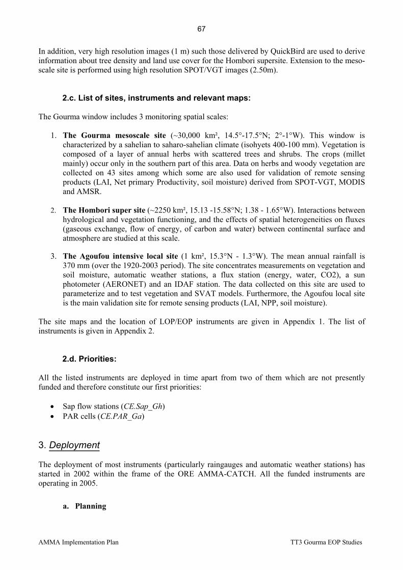
AMMA Implementation Plan TT3 Gourma EOP Studies
In addition, very high resolution images (1 m) such those delivered by QuickBird are used to derive information about tree density and land use cover for the Hombori supersite. Extension to the meso-scale site is performed using high resolution SPOT/VGT images (2.50m).
2.c. List of sites, instruments and relevant maps: The Gourma window includes 3 monitoring spatial scales:
1. The Gourma mesoscale site (~30,000 km², 14.5°-17.5°N; 2°-1°W). This window is characterized by a sahelian to saharo-sahelian climate (isohyets 400-100 mm). Vegetation is composed of a layer of annual herbs with scattered trees and shrubs. The crops (millet mainly) occur only in the southern part of this area. Data on herbs and woody vegetation are collected on 43 sites among which some are also used for validation of remote sensing products (LAI, Net primary Productivity, soil moisture) derived from SPOT-VGT, MODIS and AMSR.
2. The Hombori super site (~2250 km², 15.13 -15.58°N; 1.38 - 1.65°W). Interactions between
hydrological and vegetation functioning, and the effects of spatial heterogeneities on fluxes (gaseous exchange, flow of energy, of carbon and water) between continental surface and atmosphere are studied at this scale.
3. The Agoufou intensive local site (1 km², 15.3°N - 1.3°W). The mean annual rainfall is
370 mm (over the 1920-2003 period). The site concentrates measurements on vegetation and soil moisture, automatic weather stations, a flux station (energy, water, CO2), a sun photometer (AERONET) and an IDAF station. The data collected on this site are used to parameterize and to test vegetation and SVAT models. Furthermore, the Agoufou local site is the main validation site for remote sensing products (LAI, NPP, soil moisture).
The site maps and the location of LOP/EOP instruments are given in Appendix 1. The list of instruments is given in Appendix 2.
2.d. Priorities:
All the listed instruments are deployed in time apart from two of them which are not presently funded and therefore constitute our first priorities:
• Sap flow stations (CE.Sap_Gh) • PAR cells (CE.PAR_Ga)
3. Deployment The deployment of most instruments (particularly raingauges and automatic weather stations) has started in 2002 within the frame of the ORE AMMA-CATCH. All the funded instruments are operating in 2005.
a. Planning
67

AMMA Implementation Plan TT3 Gourma EOP Studies
The period of deployment for each instrument is given in Table 1. The associated field missions are given in Tables 2 and 3.
68

AMMA Implementation Plan TT3 Gourma EOP Studies
Table 1. Planning of instrument deployment
2004 2005 2006 2007 Form # Inst. Code Description exist 1 2 3 4 5 6 7 8 9 10 11 12 1 2 3 4 5 6 7 8 9 10 11 12 1 2 3 4 5 6 7 8 9 10 11 12
EF1 AE.GPS_1 GPS stations EF6 AE.Ba.CO2_G Tethered balloon EF7 AE.Flux_G Network of 4 flux stations EF14 CE.SW_G Network of SW stations EF15 CE.VegSoil._G Vegetation studies EF16 CE.PAR_Ga PAR interception station EF17 CE.Sap_Gh Sap flow stations EF30 AE.DUST_ST 1 AERONET Photometer EE9 AE.Flux_G Network of flux stations EE? AE.RS_T1 Acoustic sodar LF1 AL.Met_G 2 weather stations
LF16 CL.Rain_G 8 recording raingauges LF26 CL.Depot_RW 1 IDAF station
- CL.Photometer 1 AERONET Photometer - UHF_BMKO TT1
to be defined
69

AMMA Implementation Plan TT3 Gourma EOP Studies
Table 3. Planning of missions 2005
2005 EOP January Feb. March April May June July August Sept. October Nov. Dec. 1 2 3 4 1 2 3 4 1 2 3 4 1 2 3 4 1 2 3 4 1 2 3 4 1 2 3 4 1 2 3 4 1 2 3 4 1 2 3 4 1 2 3 4 1 2 3 4EF1 AE.GPS_1 GPS stations EF6 AE.Ba.CO2_G Tethered balloon EF7 AE.Flux_G Network of 4 flux stations
EF14 CE.SW_G Network of SW stations EF15 CE.VegSoil._G Vegetation studies EF16 CE.PAR_Ga PAR interception station EF17 CE.Sap_Gh Sap flow stations EF30 AE.DUST_ST Cinzana photometer EE9 AE.Flux_G Network of flux stations EE? AE.RS_T1 Acoustic sodar LF1 AL.Met_G Weather stations
LF16 CL.Rain_G 8 recording raingauges LF26 CL.Depot_RW 1 IDAF station
- CL.Photometer 1 AERONET Photometer - UHF_BMKO TT1
field mission for people permanently in Bamako to be defined
field mission for people in mission in Mali (P: # people)
70

AMMA Implementation Plan TT3 Gourma EOP Studies
Table 2c. Planning of missions 2006
2006 EOP January Feb. March April May June July August Sept. October Nov. Dec. 1 2 3 4 1 2 3 4 1 2 3 4 1 2 3 4 1 2 3 4 1 2 3 4 1 2 3 4 1 2 3 4 1 2 3 4 1 2 3 4 1 2 3 4 1 2 3 4EF1 AE.GPS_1 GPS stations EF6 AE.Ba.CO2_G Tethered balloon EF7 AE.Flux_G Network of 4 flux stations
EF14 CE.SW_G Network of SW stations EF15 CE.VegSoil._G Vegetation studies EF16 CE.PAR_Ga PAR interception station EF17 CE.Sap_Gh Sap flow stations EF30 AE.DUST_ST Cinzana photometer EE9 AE.Flux_G Network of flux stations EE? AE.RS_T1 Acoustic sodar LF1 AL.Met_G Weather stations
LF16 CL.Rain_G 8 recording raingauges LF26 CL.Depot_RW 1 IDAF station
- CL.Photometer 1 AERONET Photometer - UHF Bamako TT1
field mission for people permanently in Bamako to be defined
field mission for people in mission in Mali (P: # people)
71

AMMA Implementation Plan TT3 Gourma EOP Studies
b. Logistical considerations Due to the location of the Gourma site within the sahelian pastoral region, logistical constraints have to be taken into account. This can be done if requests for missions are transmitted to the Task leaders at least 2 months prior the mission. Particularly, the need for vehicles and drivers should be specified as soon as possible because it can be a limiting factor. The Agoufou local site is located at 950 km from Bamako what means that a minimum of a full day journey is necessary to reach the site. The accessibility to the Bamba site cannot be guaranteed due to episodic security problems encountered within this area.
Vehicles The IRD Centre in Bamako has 5 4-wheel-drive vehicles. Among them, one is dedicated to the AMMA team. A maximum of 3 vehicles can be used by the AMMA teams at the same time. Consequently, in case of extra needs, a possible solution is either to obtain a vehicle from another IRD Centre of West Africa (Ouagadougou for instance) or to hire 4WD vehicles and drivers in an agency in Bamako.
Infrastructures
Office in Bamako In Bamako, AMMA teams are housed in the IRD Centre which offers usual telecommunications and an internet access.
Housing in Hombori during field missions Housing for people in mission for field work is possible in an encampement hotel located in the Hombori village which is at about 30 km from the Agoufou local site. “The hotel is basic but pleasant. Sanitation is good with cold shower, basin and flushing toilet. Food is good but basic. Power is only supplied from a fuel generator” (Colin Lloyd‘s comments after his first visiting period in August 2003). Daily cost is 4000 CFA what includes lodging and meals. A participation of 4000 CFA/person/day is asked for covering extra costs (improved meals, mineral water,…).
Human resources Office in Bamako The AMMA permanent team in Bamako is 3 people (Josiane Seghieri, François Lavenu and Franck Timouk). F. Lavenu is responsible of the EOP/LOP logistics. The team can provide help and advices for logistical problems. Hotel booking in Bamako can also be done by the IRD Centre.
Technical maintenance in the field
72

AMMA Implementation Plan TT3 Gourma EOP Studies
Depending on the need, local ‘technicians’ and guardians can be contracted, trained, and thus can maintain a series of instruments during the whole operation period.
Communications
Bamako
The IRD Centre is equipped with usual telecommunication facilities and a good internet connection.
Gourma site The village of Hombori has only one telephone and mobile phones cannot be used within the Gourma site. The nearest facilities are found in Gao at about 230 km from Hombori. A satellite phone can be useful.
4. Partnership a) Field observations
Partnerships for field observation mainly involve:
• Direction Nationale de la Météorologie : Radio-soundings (Gao and Tombouctou), GPS stations (Gao and Tombouctou), UHF (Bamako), Rainfall station network.
• Institut d’Economie Rurale (IER)/Centre Régional de Recherche Agronomique de Gao (CRRA-Gao) : Vegetation monitoring (Gourma). The CRRA-Gao is responsible of the vegetation site network around Bamba.
• Institut Polytechnique Rural (IPR) de Katibougou : Aerosols/Rainfall/Chemistry (Agoufou), vegetation (Gourma).
• Département de Physique, Faculté des Sciences et Techniques (FAST), Université de Bamako : Photometer (Agoufou).
• Ecole Nationale d’Ingénieurs : UHF Radar (Bamako). • Direction Nationale de l’Hydraulique :
b) Training program • Students from IPR : 2 engineer students in 2005
5. Organisation of the TT. a) Leaders, core group, membership
Task Team leaders : Eric MOUGIN [email protected] Josiane SEGHIERI [email protected] Lassine DIARRA [email protected] IER / AMMA-Mali
73

AMMA Implementation Plan TT3 Gourma EOP Studies
Core Group members : François LAVENU [email protected] Logistics, ST2 representative Franck TIMOUK [email protected] EOP Instrumentation Aly SOUMARE [email protected] Bamba sites/ROSELT Mohamed KOITE [email protected] Meteorology Representative Colin Lloyd [email protected] TT2 fluxes representative Corinne GALY-LACAUX [email protected] IDAF Representative The full list of TT3 members is given in Appendix 3
b. Internal coordination
Diffusion of information is made by email using the member list given in Appendix 3. Meetings are planned several times a year in Bamako between the Core team and the AMMA-Mali committee.
c. How are handled requests for new instruments?
Requests must be sent to the TT leaders, at least 3 months prior installation, with all the relevant information. Requests for malian partnership if any, as well as for technical assistance must be sent at the same time. Francois Lavenu in Bamako can provide help and advice for logistic problems and custom formalities. Instruments to be installed in Mali must be sent via air freight to Bamako airport.
d. External diffusion of the information and reporting External diffusion should be based on web page support.
6. Coordination with other TTs The leaders of TT3 are in close inter-relation with TT2 (Colin Lloyd and Chris Taylor), TT1 (Doug Parker) and with the task teams of the two others meso-scale sites : TT4 (Niger) and TT5 (Benin). Coordination with the CATCH-, IDAF- and AERONET- ‘Observatoire de Recherche sur l’Environnement (ORE)’ is also effective.
7. Ancillary information, references, logistic forms, site document Site maps for the different scales are given in the Appendix 1.
74

AMMA Implementation Plan TT3 Gourma EOP Studies
Appendix 1
Site Maps
75
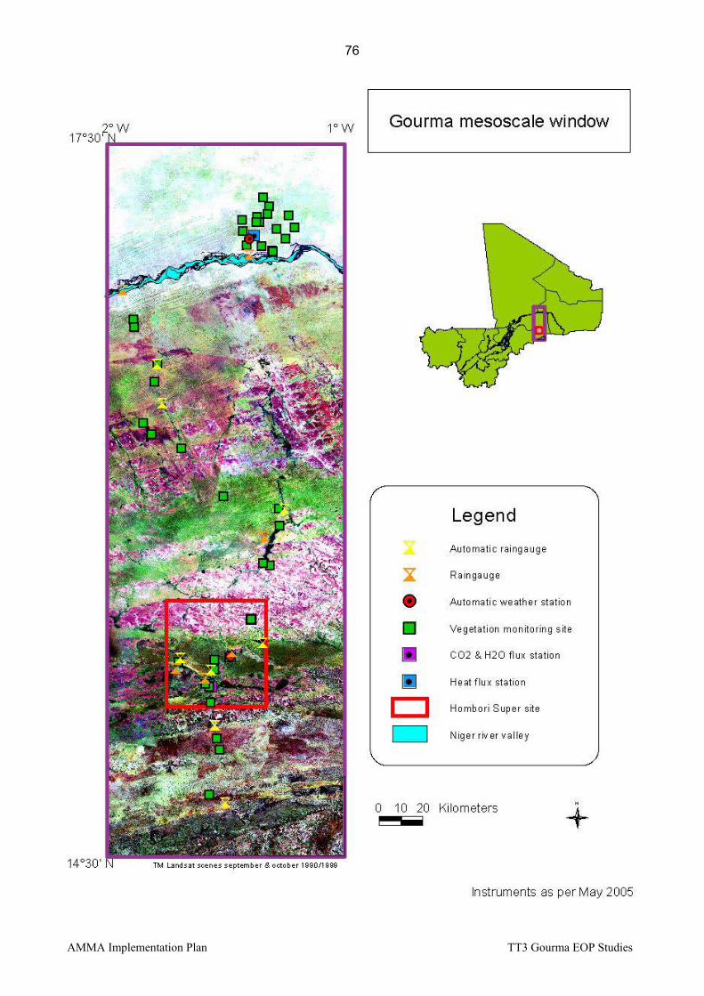
AMMA Implementation Plan TT3 Gourma EOP Studies
76

AMMA Implementation Plan TT3 Gourma EOP Studies
77

AMMA Implementation Plan TT3 Gourma EOP Studies
Hombori Supersite (15.4°N, 1.6°W)
Agoufou local Site (15.3°N, 1.5°W)
Bamba local Site (17.1°N, 1.3°W)
Niger River
Rainfall 50 mm
350 mm
450 mm
300 mm
100 mm
Gourma mesoscale Site (3° x 1°)
78
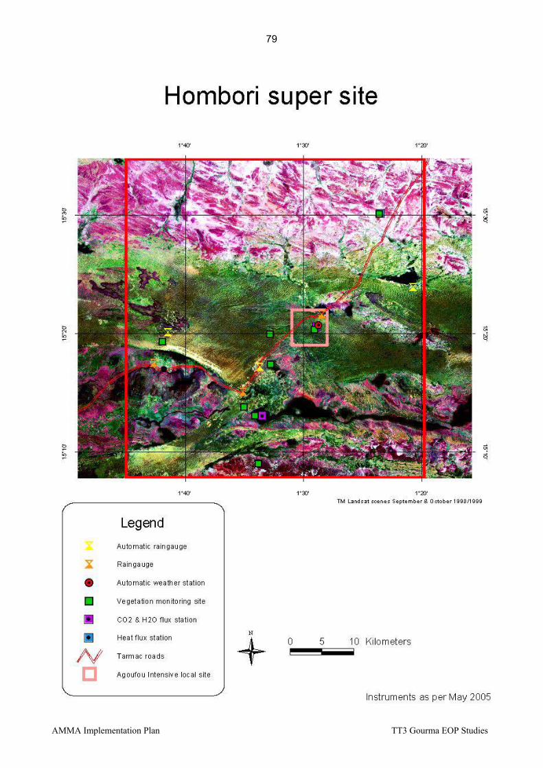
AMMA Implementation Plan TT3 Gourma EOP Studies
79
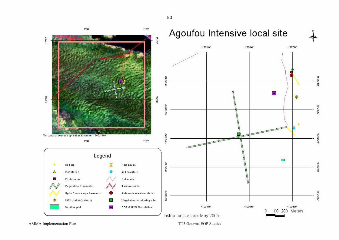
AMMA Implementation Plan TT3 Gourma EOP Studies
80

AMMA Implementation Plan TT3 Gourma EOP Studies
Appendix 2
List of TT3 instruments
81

AMMA Implementation Plan TT3 Gourma EOP Studies
List of TT3 instruments Nomenclature: Form #: XY# with X=L(LOP)/E(EOP)/S(SOP); Y=F(French)/E(European) instrument Instrument code XY.name_G(d)(c): X=A(Atmosphere)/C(Continent)/O(Ocean) ; Y=L/E/S, idem form # ; G(h)(a)=G(Gourma site)/(h)(Hombori supersite)/(a)(Agoufou=local) Period Form # Code PI Name E-Mail Address Instrument Platform
EOP EF6 AE.Ba.CO2_G L. Kergoat (CESBIO) [email protected] Tethered balloon for CO2 profiles in the nocturnal boundary layer
Agoufou
EOP EF7 AE.Flux_G F. Timouk (CESBIO) [email protected] Network of 4 flux stations (2 HF and 2 CO2/H2O)
Gourma
EOP EF14 CE.SW_G P. de Rosnay (CESBIO)
[email protected] Network of 9 automatic stations for soil moisture measurements.
Gourma
EOP EF15 CE.VegSoil._G J. Seghieri (CESBIO) [email protected] Network of 1 x 1 km² vegetation sites, soil and vegetation chemical analyses, Ecophysiology measurements
Gourma
EOP EF16 CE.PAR_Ga V. Demarez (CESBIO) [email protected] Network of automatic PAR cells for grass and tree canopies
Agoufou
EOP EF17 CE.Sap_Gh V. Le Dantec (CESBIO) [email protected] Automatic measurements of sap flow on trees.
Hombori
LOP LF1 AL.Met_G F. Timouk (CESBIO) [email protected] 2 automatic weather stations Gourma LOP LF16 CL.Rain_G F. Lavenu (CESBIO) franç[email protected] Network of 8 automatic raingauges Gourma LOP LF26 CL.Depot_RW C. Galy-Lacaux (LA) [email protected] 1 IDAF station Agoufou LOP - CL.Photometer P. Goloub (LOA) [email protected] PHOTON/AERONET Photometer Agoufou
82

AMMA Implementation Plan TT3 Gourma EOP Studies
Instruments relevant to other Task Teams
Nomenclature: Form #: XY# with X=L(LOP)/E(EOP)/S(SOP); Y=F(French)/E(European) instrument Instrument code XY.name_G(d)(c): X=A(Atmosphere)/C(Continent)/O(Ocean) ; Y=L/E/S, idem form # ; G(h)(a)=G(Gourma site)/(h)(Hombori supersite)/(a)(Agoufou=local) Period Form # Code PI Name E-Mail Address Instrument Platform
M.N. Bouin (IGN) [email protected] EOP EF1 AE.GPS_1 Olivier Bock (SA) [email protected]
GPS stations Meridional transect: Gao - Tombouctou
EOP EF30 AE.DUST_ST Bernadette Chatenet [email protected]
PHOTON/AERONET Photometer Sahelian Transect Cinzana
EOP EE9 AE.Flux_G C. Lloyd (CEH) C. Taylor (CEH)
[email protected] [email protected]
Flux station network Benin, Gourma - Mali, Niger
EOP EE? AE.RS_T1 D. Parker (U. Leeds) [email protected] Acoustic sodar Transect Sahel EOP - UHF_BMKO B. Campistron [email protected] UHF Bamako Bamako
83
AMMA Implementation Plan TT3 Gourma EOP Studies
Appendix 3
List of TT3 members
84

AMMA Implementation Plan TT3 Gourma EOP Studies
Name Surname E-Mail Address Affiliation Country Associated Instrument Instrument /
Position Bâ Abdramane [email protected] FAST Mali AERONET Sun photometer CL.Photometer Bennie Jon [email protected] CEH UK Vegetation surveys CLASSIC Bock Olivier [email protected] SA France GPS stations AE.GPS_1, AS.GPS_1 Bouin Marie-Noëlle [email protected] IGN/ENSG France GPS stations AE.GPS_1, AS.GPS_1 Campistron Bernard [email protected] LA/UPS France UHF Bamako TT1 Chatenet Bernadette [email protected] LISA France AERONET Sun Potometer AE.DUST_ST Damesin Claire [email protected] ESE/Orsay France Licor gaz exhange devices CE.VegSoil._G Delon Claire [email protected] LA/UPS France Soil NOx emissions ECCO/PNBC Demarez Valérie [email protected] CESBIO France PAR cells CE.PAR_Ga De Rosnay Patricia [email protected] CESBIO France Soil moisture network CE.SW_G
Diarra Lassine [email protected] IER Mali President Malian AMMA Committee, vegetation surveys AMMA Mali
Diop Babakar [email protected] FAST Mali IDAF CL.Depot_RW Epron Daniel [email protected] EEF/Nancy France Licor gaz exhange devices CE.VegSoil_G Dembélé Fadiala [email protected] IPR Mali Vegetation surveys AMMA Mali Famouké Traoré [email protected] ENI Mali UHF Bamako AMMA Mali Fediere Gilles [email protected] IRD Mali Head IRD in Mali Head IRD in Mali Fofana Al Mostapha [email protected] DNH Mali Hydrology AMMA Mali Frison Pierre-Louis [email protected] UMVL France Satellite validation Satellite validation Galy-Lacaux Corinne [email protected] C. Galy-Lacaux France IDAF station CL.Depot_RW Guichard Françoise [email protected] CNRM France Tethered balloon AE.Ba.CO2_G Goloub Philippe [email protected] Uni-Lille/LOA France Sun Photometer CL.Photometer D’Herbes Jean-Marc [email protected] IRD/Montpellier France Vegetation studies ROSELT Hiernaux Pierre [email protected] CESBIO France Vegetation studies CE.VegSoil_G Karambé Moussa [email protected] FAST Mali Vegetation studies AMMA Mali Kergoat Laurent [email protected] CESBIO France Tethered balloon AE.Ba.CO2_G Koité Mohamed [email protected] DNM Mali Rainfall network AMMA Mali
Lavenu François franç[email protected] CESBIO Mali Raingauge network , AERONET CL.Rain_G,CL.Photometer
85

AMMA Implementation Plan TT3 Gourma EOP Studies
Le Dantec Valérie [email protected] CESBIO France Sap flow stations CE.Sap_Gh Lloyd Colin [email protected] CEH UK Flux station network AE.Flux_G Mazzega Pierre [email protected] LEGOS France Remote sensing studies TOSCA Mercado Lina [email protected] CEH UK Vegetation surveys CLASSIC Mougenot Bernard [email protected] CESBIO France Soil characterization CE.VegSoil_G
Mougin Eric [email protected] CESBIO France Vegetation studies TT Leader, CE.VegSoil_G, CE.SW_Gh, CE.PAR_Ga
Parker Doug [email protected] U. Leeds UK Radio sounding network AE.RS_T1 Saïd Frédérique [email protected] LA/UPS France UHF Bamako TT1 Seghieri Josiane [email protected] CESBIO Mali Vegetation studies CE.VegSoil._G Serça Dominique [email protected] CNRS/LA France Soil NOx emissions ECCO/PNBC Sissoko Mamadou [email protected] ASECNA Mali UHF Bamako AMMA Mali Soumaré Aly [email protected] IER Mali Vegetation surveys AMMA Mali Taylor Chris [email protected] CEH UK Network of flux stations AE.Flux_G, TT2
Timouk Franck [email protected] CESBIO France Automatic weather stations, flux stations AL.Met_G, AE.Flux_G
86

AMMA implementation Plan TT4, Niamey EOP Studies (24 May 2005)
TT4 – EOP integrative studies on the Niger meso-site Context The whole West Africa has experienced a severe drought since the end of the 1960’s. This was more pronounced in the Sahel than in naturally more humid areas. During the same period, population growth remains strong (and in Niger, the growth rate is increasing), causing a severe land use change and in most parts, a generalized soil degradation. It is worth to observe that population growth is higher where drought is stronger. Consequently, it has been observed a significant reduction of rivers discharge: Senegal river annual runoff decrease in 60% (1971-90 vs 1951-70) and Niger river in 55%. The decrease in rainfall amount for the same periods is 25-30% depending of the region. Dust transport and aeolian erosion also increased significantly. Historic The knowledge in hydrological Sahelian environment was greatly improved in the last decades:
- a great number of catchment were monitored since the 1950’s particularly by Orstom (Nouvelot, 1993)
- a significant advance was realised by Casenave and Valentin (1989) who determined soil water behaviour and hydrodynamics for all types of soil crusts;
- the HAPEX Sahel experiment allowed the study of the complete water cycle in this region, including atmospheric data, soil water monitoring and dust measurements (see Hapex Sahel special issue of Journal of Hydrology, 1997);
- during the 1990’s and the beginning of the 2000’s, an hydrogeological survey completed the surface water monitoring remained in place after HAPEX experiment (Favreau, 2000; Leduc et al, 2001).
- Recently, Taylor and Lebel highlighted the likely correlation between continental surface and location of the convection; thus, retroaction of surface on atmospheric processes should be demonstrated.
Dust aerosol effect on the climate change is one of the large incertitude pointed out by IPCC 2001. The Sahel is one of the areas where yearly dust concentration is the highest of the world. In last decades new information on the aerosol atmospheric content in the Sahelian part of West Africa are derived from satellites observations, sun photometer network (AERONET) and field study. Desert dust sources are better known (i.e. Goudie and Middleton 2001), climatology of desert dust was improved for instance by Brooks and Legrand (2000) and local field studies determined periods and surface types when and where dust erosion occurs in the Sahel (i.e. Bielders et al. 2004). A clear correlation was established between drought occurrences and increase in desert dust load in the atmosphere not only in the Sahel (N’Tchayi et al. 1994) but also far from African sources in the transport zone of Caribbean islands (Prospero and Lamb, 2003). Problematics The previous experiments enable the scientific community to better understand the water cycle behaviour in the Sahel, and its spatial and temporal variability, the latter being due mainly to the great drought of Sahel. They highlight the non-linearity of hydrological behaviour of the environment, through two main conclusions performed after intensive field measurements including meteorological, hydrological and hydrogeological surveys, and land use and vegetation data:
87

AMMA implementation Plan TT4, Niamey EOP Studies (24 May 2005)
- the first one is a rise in water table level on the endoreic areas of Niamey square degree, since at least the 1950’s; which remained and reinforced during the 1970-2005 period despite of the rainfall strong decreasing; the water table recharge is increasing at an increasing rate for at least two decades (Desconnets, 1993; Favreau, 2000; Leduc et al, 2001);
- the second one is an increase in runoff coefficient and generally also in discharge of the Sahelian rivers, evidenced by Albergel in a transect of experimental catchments in the 80’s (Albergel, 1987, Pouyaud et al., 1987): it has been confirmed for the Nakambé river (Mahé et al., 2002) and for the right edge tributaries of Niger river during its Sahelian transfer (Amani and Nguetora, 2002; Mahé et al., 2003). This increase was observed also and mainly during the drought years. At Niamey station, the immediate flood (September) due to local creeks flows is being higher than the “normal” flood of the river, which arrives in January, five times since 1984; that never occurred before 1984, and that is an evidence of river regime changes. Otherwise, the right afluents of Niger river in Niger (country) experienced an increase of their annual discharge in the Sahelian area, but a more normal (taking into account the strong rainfall decrease) decrease in annual discharge in the Sudano-sahelian areas.
Otherwise, at the meso-scale, there is a spatial correlation between location of the first rain field in the season and location of the following rain field, suggesting an impact of soil surface moisture and/or darkness and/or roughness, on the convection. At regional scale it has been showed that rainfall amount in the Sahel is high (low) on year X when soil moisture is high (low) on Guinean regions at the end of year X-1. In spite of large increase of knowledge on desert aerosol topic, it is clear that the quantification of mineral dust emissions in the Sahel remains questionable, especially during drought periods. All the studies show how sensitive to climatic parameters and their variations at any time scale (daily, seasonal, interannual) these emissions are. Despite a possible overestimation of the cultivated areas contribution to present dust emissions, human disturbances and their possible impact on the local dust emissions should increase in the next future and must be documented right now. The degradation in vegetation cover is likely one of the common element explaining water cycle, dust and climate changes at the regional and at the meso-scale. Scientific questions to answer Therefore, the main scientific question to answer is to understand and to explain this non-linearity, in space (sites with increasing runoff, others with decreasing one) at in time (increasing discharge and water table recharge in the same time when rainfall decreased significantly). Therefore, it is worth to notice that vegetation is the key of the problem; climate change is real, but land use change seems to be the best explaining cause of the increase in surface water despite the rainfall decreased severely. There is a need to understand why some processes are valuable until a spatial threshold and no more after that:
- Why do the discharge increase, despite the rainfall decreases in Sahelian areas and not in Sudanian ones, where rainfall reduction was lower ?
- Why do the rise in water table recharge increase since the 1980’s ? - What part of the increasing runoff is explained by PE reduction (due to vegetation
harvesting) either by the reduction in soil water holding capacity ? - How much mineral dust is emitted from the Sahel, and how much is due to land use
(cultivation and pasture) ?
88

AMMA implementation Plan TT4, Niamey EOP Studies (24 May 2005)
- Which are the main factors controlling the variability of mineral dust emissions at the seasonal and interannual time scales ? Which is the influence of changes in precipitations compared to other dynamical parameters ? Do precipitations act on dust emissions through changes in vegetation cover only or is there any additional changes in the wind pattern associated with the drought period that could explain the enhancement of dust emissions ?
- What will be the impacts of climatic changes and/or of the increase of land use on the dust emissions ?
- What is the relation between dust transport and meningitis occurrences and between soil moisture and malaria prevalence ?
- What is the role of land use change in climate change ? - Has the vegetation harvesting a role in the rainfall reduction ? Is the latter due to
roughness evolution ?, or to albedo increase ?, or to PE reduction ? . What is the motion of retroaction between surface and atmosphere ?
The AMMA program is the opportunity for the scientific community of the Earth Sciences to get an explanation for all these crucial questions. This is overall the hope of explain also the interactions between continental surfaces and the convection processes. References Albergel, J., 1987. Genèse et prédétermination des crues au Burkina Faso; du m² au km², étude des paramètres hydrologiques et de leur évolution. Thèse Université Paris 6, Editions de l’Orstom, 330 p., 1988. Amani, A..and Nguetora, M., 2002. Evidence d’une modification du régime hydrologique du fleuve Niger à Niamey. In Van Lannen, H., Demuth, S. (Eds). FRIEND 2002 regional Hydrology: bridging the gap between research and practice. Proc. of Friend Conf. Cap Town, S.A., IAHS Pub. 274: 449-456. Casenave, A., et Valentin, C., 1989. Les états de surface de la zone sahélienne ; influence sur l’infiltration. Editions de l’Orstom, 224 p., Paris. Desconnets, J-C., 1993. Typologie et caractérisation hydrologique des systèmes endoréiques en milieu sahélien (Niger ; degré carré de Niamey). Thèse Université Montpellier 2, 330 p. Favreau, G., 2000. Caractérisation et modélisation d’une nappe phréatique en hausse au Sahel : dynamique et géochimie de la dépression piézométrique naturelle du kori de Dantiandou (sud ouest du Niger). Thèse Université Paris 11, 270 p. Le Barbé, L. et T. Lebel. (1997). Rainfall climatology of the HAPEX-Sahel region during the years 1950-1990. J. of Hydrol. 188-189: 43-73. . Leduc, C., G. Favreau, P. Shroeter. (2001). Long term rise in a Sahelian water-table: the Continental Terminal in South-West Niger. J. of Hydrol., 243: 43-54. Mahé, G. et al. (2003). Augmentation récente du ruissellement de surface en région soudano-sahélienne et impact sur les ressources en eau. In : Hydrology of the mediterranean and semi-arid regions. Proceedings of the International Conference, Montpellier. IAHS Publication n°278:215-222. Pouyaud, B., 1987. Variabilité spatiale et temporelle des bilans hydriques de quelques basins versants d’Afrique d el’Ouest en liaison avec les changements climatiques. In : Solomon,S.I., Beran, M., Hogg, W. (Eds), The influence of climate change and climate variability on the hydrologic regime and the water resources. Proceeedings of Vancouver Symposium, August 1987, IAHS Publ. N0 168, pp. 447-461. N’Tchayi Mbourou, G. M., J. Bertrand, M. Legrand, and J. Baudet, Temporal and spatial variations of the atmospheric dust loading throughout West Africa over the last thirty years, Ann. Geophys., 12, 265-273, 1994.
89
AMMA implementation Plan TT4, Niamey EOP Studies (24 May 2005)
Brooks, N. and M. Legrand, Dust variability over northern Africa and rainfall in the Sahel, in Linking land surface change to climate change, Mc Laren S. J. and Kniverton D. eds, Dordrecht, Kluwer, 2000. Goudie, A.S. and N.J. Middleton, Saharan dust : Nature and consequences, Earth Sci. Rev., 56, 179-204, 2001. Bielders, C.L., Rajot, J.L., Michels, K. L'érosion éolienne dans le Sahel Nigérien : influence des pratiques culturales actuelles et méthodes de lutte. Sécheresse, 15(1):19-32. 2004 Prospero, J. M., and P. J. Lamb (2003), African droughts and dust transport to the Caribbean: Climate change implications, Science, 302, 1024–1027. Introduction The so-called “Niamey square degree” is the central site of AMMA experiment in surface processes, being located in Sahelian area, between the Sudanian site of Ouémé basin (Benin) and the dry-sahelian site of Hombori, in Mali. There are located sites of Aeronet and IDAF networks, and of the mineral dust monitoring transect (Sénégal (M’bour), Mali (Cinzana) Niger (Banizoumbou) of AMMA. As detailed in §2b and displayed on maps of Appendix 1, this is composed by:
- The Niamey meso-site (denoted N), initially defined for - and run ever since - the EPSAT experiment, covering the “Niamey square degree” with a third degree added westward of the former
- The meso-scale “kori of Dantiandou” basin (kori = oued or wad), abbreviated Nkd, which is a “topographical” basin with not a hydrological functioning; it corresponds to a hydrogeological basin, being the extension of the piezometric depression of the Dantiandou kori.
- The Niamey Central Super Site of the core area of this depression (Nc in appendix 1) - Three main experimental sites:
o – Wankama basin (Ncw) o – Tondi Kiboro site o – Koma Koukou site (cf. TT2b)
- Banizoumbou station (Met station, Aeronet and IDAF stations) - Some other experimental sites:
o – Kafina, Sofia Bangou, Zindarou This document aims to be the implementation plan of all the EOP measurements in the Niamey site. Please note however that the dust & aerosols component of the program are primarily attached to the TT2b team and document, and only secondarily, for operations in Niger, to the present TT4.
1. Scientific justification and objectives The Niger site has been chosen because of its representativeness of Sahelian context (current drought, significant proportion of endoreic areas, strong land use changes) and because a lot of previous researches existed and highlighted certain scientific questions which remain unresolved; this is the case particularly on the un-linearities cited in introduction. Then AMMA program gives the opportunity to focus on these precise questions, and to study specially the interactions between continental surfaces and atmospheric processes what appeared, according to previous or current studies, to be the main key of explanation of recent climate changes.
90

AMMA implementation Plan TT4, Niamey EOP Studies (24 May 2005)
Hydrology: The hydrological EOP measurements on the SW-Niger mesoscale site mostly constitute a
denser sampling in space and time of the water cycle and related processes. It is based on the LOP monitoring carried out since 2001 (and earlier for rainfall, local runoff and aquifer recharge) and described in ST1 (LOP monitoring). The emphasis is on the documentation of the seasonal cycle and its variability (in space; inter-annual, and intra-seasonal for some processes). More specifically the objectives in term of process studies and modeling are the following:
- Investigating small scale variability of certain variables: rainfall (instruments CE.Rain_Nc
and CL.Rain_N); soil moisture (instruments CE.SW_Nc and CE.SWsan_Nc), runoff (instruments CE.Run_Nc and CE.Pond_Nc), PE (instruments AE.Flux_Ncw, AE.Flux_Nc, and AL.Met_Nc), aquifer recharge (CE.Gwat_Nc and CL.Gwat_N) and their impact on the water budgets at larger scale.
- Joint modeling of surface hydrology and the aquifer at the mesoscale (Kori de Dantiandou, see list of sites).
- Investigating the role of vegetation in runoff, infiltration, soil moisture and aquifer recharge, and determine the thresholds and boundaries of each process.
Being the vegetation the main factor of current hydrological processes change, it is worth to have a permanent actualization of vegetation cover, including bare soils and cultivated areas.
Vegetation. There is nowadays a great series of aerial data enabling the constitution of an evolutive GIS which could improve significantly the knowledge of the evolution of hydrological basin behavior: aerial pictures of 1950, 1975 and 1992 (IGN and IGNN), Corona (USA) pictures of 1965, Landsat and SPOT satellite products since the 1980’s, and since 2002, satellite data with spatial great resolution (5m X 5 m, locally 1m X 1m).
Then update the 1992 vegetation map over the 1°x1° square to quantify the vegetation change and its impact on the water cycle, is now a priority, but create a posteriori mapping of older periods can provide a good information for hydrological modelling. The other task to achieve in the next years are:
- Analyse the seasonal cycle of the vegetation – focusing on millet, fallow trees – in interaction with water constraints.
- Provide a re-parameterisation of the Treegrass model (initially developed for humid tropical eco-systems) and upscaling towards a larger scale model (Tgpix) (instrument CE.Veget_Ncw).
- Investigating the influence of land use changes in water cycle evolution based on farm surveys over the 1°x1° square to validate the SARRA_H crop simulation model for regional yield forecasting and climate change impact studies.
A planned long term project, included in OVNI program (Vegetation and Water in Niger, French funded) aims to create a new artificial vegetation during the AMMA period (planting of tree hedges in a significant area (hundreds of km²) and to monitor soil moisture, rainfall and micro-climate data as well as crops productivity during one or two decades after the planting.
Aerosols and chemistry (see TT2b) Aims of dust aerosol experiments are to monitor the dust mass concentration and deposition at
the ground level and the dust location and transport in the atmospheric column to validate
91

AMMA implementation Plan TT4, Niamey EOP Studies (24 May 2005)
dust emission/transport model (instruments AE_Dust_ST). The final objective is to obtain a budget of dust at the Sahel scale. The EOP Banizoumbou site is one of the three stations (the two others are Segou-Cinzana in Mali and M’bour in Sénégal) forming a Sahelian transect.
More detailed studies aim to investigate processes like the role of cultivated vegetation or soil type on local erosion occurrences.
During SOP B emission flux and dusts characteristics will be measured (Instrument AS Dust Flux).
The chemistry study (IDAF) monitors the inorganic and organic aerosol and gas (instrument CL.Depot_RW). It aims at understanding the interaction between organic and inorganic aerosols and gas during the seasonal cycle.
Validation of aircraft and remote sensing measurement. Site documentation in preparation of the SOP campaigns (TT8, TT9).
- Satellite validation: - - radar (ASAR ENVISAT): during the rainy season 2004, 8 measurements
campaigns were made to validate with this new sensor in soil moisture; 5 villages, with 6 observations points in each one (in different land use) : 10 measurements (Thetaprobe) and 2 gravimetric water content measures at each point;
- - SPOT 5: land use map actualized in the entire SPOT 5 scene (60 X 60 km) owing to land observations and description as well as micro-roughness measurements.
- - 2005 to 2007: continuation of soil moisture, and soil roughness monitoring; annual actualization of land use map;
- a pool mapping was began in 2004; this needs validation; this would enable to monitor pool number, pool extension and pool duration during AMMA EOP period and to validate a pool counting process, very important in this endoreic area. Modeling of coupled processes. Particular emphasis is given to the coupling of hydrological models and vegetation dynamics models at the local scale and then on the supersite.
Health. An AMMA application program which investigates the climatic part of malaria transmission hazard according to environmental typology. Investigating the climate, aerosols and atmosphere conditions concomitant of meningitis outbreaks.
Agronomic applications. The aim is to investigate the impacts of monsoon and climate evolution on crops (millet firstly) and the adaptation of rural population to these changes.
2. Observing strategy a. Overall strategy for hydrologic studies It conforms to the overall strategy of mesoscale sites as enunciated in the first part of this document. The SW-Niger site is typical of the central Sahel environment and climate. Mesoscale processes were heavily documented in 1991-1992. The ensuing long term monitoring of the rainfall and water table recharge have shown a very significant modification of the water balance linked to both the drought and the degradation of the vegetation. The enhancement of observations during the EOP aims at further analyzing the processes that couple the various compartments of the hydrologic cycle, and more
92
AMMA implementation Plan TT4, Niamey EOP Studies (24 May 2005)
specifically the interactions between water and vegetation as well as the spatial distribution of groundwater recharge. The observations strategy takes into account some specific features of the area, mainly the fact that the surface flow is not organized according to the usual tree-like hydrographic structure but as a mosaic of small (a few km² at most) endoreic catchments feeding into ponds or “humid” areas. Consequently, the hydrological/ vegetation studies are organized following a hierarchy of scales described below in section b.
Following the research carried out in this area over the past 10 years, one major challenge remains to better understand where the water table recharge areas are. To better document the links between the surface and the aquifers, a few experimental catchments will be studied, for the two main configurations of the region:
- gullies, because very few measurements were made in the past on these elements;
- ponds, to extend the knowledge acquired during 14 years at the Wankama site.
One open question is whether the vegetated trips of the tiger bush may also contribute to the recharge of the aquifers. Whereas it is not possible to install hydrometric stations in this context, some clue may be obtained through a soil moisture monitoring program.
To determine where, how and how quickly does water infiltrate, and eventually, recharge the aquifer depending on the environment, a soil moisture monitoring program started in 2004 and will be enhanced in 2005:
- infiltrometers (Trims type) tests will be made in order to describe topsoil (0-30 cm) hydrodynamics behavior; this is completed by soil physico-chemical analysis;
- soil moisture monitoring: these devices include 8 tensiometers (watermark) and 7 TDR sensors located from 20 to 300 cm depth; the recorder system allows for a continuous monitoring in tim;
- Neutron probe tests enable to control soil moisture up to 10 or more meters; according to previous experiments, the hole where limited to 10 meters, what is enough to record soil moisture after the roots system, when no more rising is possible by PE; these tests are mainly made after each rainy event, and then, regularly after in order to monitor soil water content depletion, what is the key of understanding of other hydrological processes;
- A piezometric network will allow the control of the water table recharge at the places previously supposed to be recharge areas.
b. Experimental sites covering the hierarchy of scales -- At the mesoscale α, one site is the support of continued and refined studies on the
interannual and intraseasonal variability of rainfall the focus being on the documentation of convective structures. This site is a 16000 km² rectangle (Niamey meso-site denoted N in the table below), over which the present raingauge network of 34 raingauges will be densified locally to allow for a better documentation of the local rainfall variability. The second site partially overlaps the Niamey meso-site (see map). It is named Kori de Dantiandou Basin (Nkd, 5645 km²). In order to control the lateral exchange terms, the boundaries were defined from the geometry of the aquifer (see map). This study area thus exceeds the limits of the original 16000 km² HAPEX-Sahel rectangle, and forms a consistent hydrological entity allowing for a study of the water balance closure. The Kori de Dantiandou Basin is however too
93

AMMA implementation Plan TT4, Niamey EOP Studies (24 May 2005)
-
large for determining precisely all the terms of the water balance equation, especially since the topography is not accurately known. Hence, a smaller meso-scale area was defined. Runoff, soil water content, infiltration and evapotranspiration must be studied at smaller scale to enable an appropriate modelling.
Name Location Description Niamey meso-site
(N) 13°-14°N; 1.6°-3°E
16000 km²
The survey of the wrongly-called “Niamey square degree” (~1.5 squ.°) started in 1990. Heavy observations in 1992, monitoring from 1994 to 2002, densification starting again in 2003. Sahelian climate with semi-arid vegetation (Millet crops, Tiger bush, …). Long series of high resolution rain data and groundwater levels.
Kori de Dantiandou Basin (Nkd)
12°15-2°57E ; 13°15’-14°15’N; 5500 km²
Kori de Dantiandou (KD) and adjacent areas. Dry vegetation cover. Land surface process studies, hydrological modelling, coupling with the sub-surface and the atmosphere. Rainfall vs vegetation spatial relationship, at the local scale.
- At the mesoscale β, a composite of endoreic areas covering 1760 km² (Nc, Niger
Central Super Site; that means the Dantiandou Basin Central Area) was chosen to compute a more comprehensive and accurate water budget. This smaller area enables the providing of regular land use maps allowing the modeling of vegetation/hydrology interactions and the evolution of water balance due to land use current changes. On this site denser measurements of the various terms of the water balance will be performed. The computation of water budgets on this super-site requires the estimation of lateral groundwater flows along the site boundaries, which can be obtained through aquifer modeling performed over the Nkd meso-scale site. Hydrology will be coupled with vegetation and its evolution using the abc-rwf model.
Name Location Description Niger Central
Super Site (Nc) 2°20’-2°49’E;
13°30’-13°52’N, 1760 km²
Subset of endoreic catchments representing core part of Nkd, with a denser raingauge network and concentration of pool, runoff, soil moisture and flux measurements. The objective is to obtain a more precise assessment of the water balance and to test the hydrological model using the modeling over Nkd to set the outer boundary condition (aquifer).
- At the local scale, 5 intensive sites – elementary endoreic units or fractions of such
units – were selected to study basic processes such as infiltration and evapotranspiration, based on flux stations and runoff plots. These 5 sites are representing the various typical situations in the super-site landscape. The main aims are to validate at this elementary scale a coupled vegetation/hydrology model and to describe the processes of changes in water and sediment budget due to land use evolution, at the plot and at the small basin scales.
Name Location Description Wankama endoreic system (Ncw)
2°39’E; 13°39’N; 2 km² Typical endoreic system, with full plateau -to- kori-bottom toposequence, including largely cultivated catchment, sandy hydrographic network (ravine, mid-catchment spreading zone, alluvial fan), and kori pond. Comprehensive hydrologic and vegetation process analyses: overland runoff, hydrographic network losses, groundwater recharge, soil moisture, evapotranspiration, crop and fallow vegetation dynamics.
Tondi Kiboro small catchment
2°42’E; 13°33’N; <1 km² Upland small catchment, along ravine running down from plateau to spreading zone. Previous hydrometric record (1993-1994) allows for investigation of changes in runoff due to severe land degradation. Analysis of channel losses.
Kafina endoreic system
2°44’E; 13°44’N; ~1 km² Upland endoreic catchment with pool
Sofia Bangou 2°43’E; 13°32’N; ~0.1 km² Plateau pond and tiger bush
94

AMMA implementation Plan TT4, Niamey EOP Studies (24 May 2005)
Banizoumbou 2°40’E; 13°32’N Meteo. and aerosol stations + pond. Malaria/Hydrology program WP 3-4
Zindarou 2°55’ E; 13°26’N Malaria /Hydrology program WP 3-4
c. Overall strategy for aerosol and chemistry studies (see TT2b) Aerosol and chemistry studies are based on local scale measurement assumed to be
representative of the larger mesoscale site. Optical dust measurements will be installed on a small plateau close to Banizoumbou where AERONET sun-photometer is running since 1995. Concentration and deposition will be measured in a fallow near the SOP dust flux station. These two time-scale measurements will be used to constrain and validate dust emission/transport/deposition models giving spatially resolved output on dust (vertically resolved concentration, deposition flux, emission flux…).
Ground based atmospheric chemistry study (IDAF) is located at the CFTEA station near the Banizoumbou village.
Local scale Banizoumbou 2°40’E; 13°32’N IDAF station
Banizoumbou 2°40’E; 13°33’N Photometer and optical dust monitoring (AE dust ST)
Koma Koukou 2°38’ E; 13°31’N Dust monitoring and SOP processes station (AE dust ST, AS dust flux)
d. Overall strategy for vegetation monitoring Vegetation monitoring on Niamey square degree is five fold:
1- Vegetation will be assessed in all experimental sites as cited in Introduction (Wankama, Tondi Kiboro, Koma koukou): current situation mapping, historical inventory (aerial pictures, IGNN and Corona, satellite files, “Pixy” inventories (Pixy is a small flying device conceived by IRD (Asseline et al., 1998). In all observation season (2005-2006 and 2007), a complete inventory of experimental site will be realized: density of vegetation, evolution intra- and inter-seasonal, on cultivated as well as in natural areas. This will made with the support of colleagues of UAM (Faculty of Biology and Geography). The specific evolution of millet is monitored since 2004 season by the partnership of Cirad and Agrhymet in 11 villages of the square degree, 3 of them located in the Central Site.
2- At Wankama basin site, a specific study of vegetation is carried out by Nicolas Boulain of HSM-Montpellier. In fallow and millet plots, the parameters for the Treegrass model are measured. It consists in a complete follow-up of phenologic, allometric and photosynthetic characteristics, including vegetation density, biomass and foliar index for shrubs, millet and herbaceous layer throughout the vegetation season. Specifically, parameters measured for all vegetation layers are: density, cover, height, phenology, biomass, foliar area, LAI, photosynthetic parameters, and roots. Crown area and plant diameter are also measured for shrubs and millet, and herbaceous species are identified over time.
3- Roselt partners are managing since the beginning of the 1990’s a set of 10 enclosed plots where vegetation is assessed in density and quality 2 times a year (once during rainy season, once during dry season);
4- ICRISAT team driven by Bruno Gérard (partners of AMMA TT4) is carrying out a heavy GIS on the Fakara (including Banizoumbou area) for twelve years: land use is monitored from the beginning of the 1990’s and
95

AMMA implementation Plan TT4, Niamey EOP Studies (24 May 2005)
previous pictures show the strong evolution of land use land cover in the last half century.
5- Field measurements of soil moisture are processed since the rainy season 2004 in 5 villages (4 to 6 sites per village, on different land uses); soil water content is measured at each sampling. This inventory is made each time that ENVISAT satellite is acquiring picture in the Central site area. Thus, a vegetation calibration could be made in the same time with few additional time and inversion.
e. Overall strategy for Health An Health/Hydrology program is developed in Niamey square degree.
Two Niamey’s institutes will participate in this project : - The CERMES, research center of the Niger Ministry of Health and associate Institute of
the Réseau International des Instituts Pasteur. - The IRD, French public agency specialized in research led in developping countries.
This program is supported by AMMA US and NOAA. The aim is to study several villages mainly during the 2005’ rainy season. The study area is situated inside the ex-Hapex site, now related to the AMMA initiative (Multidisciplinary Analysis of the African Monsoon). The scientific question is analysing all likely correlations between mosquitoes population and contamination and people malaria contamination on the one hand, soil moisture, temperature in the villages (into and out of the houses) and rainfall, on the other hand. Sampling effort will be concentrated on malaria vectors both on aquatic stages and adult mosquitoes. Previous data show good relevance of insecticide house-spraying method rather than classical CDC- light traps. Aquatic stages will be evaluated either by eye-directed rapid sampling or by dipp-in or aquatic net in cases of large breeding sites. All samples will be recorded in a GIS and all sampling sites will be GPS marked. Environment (temperature, rainfall, humidity of soil and air) will be studied by automatic apparatus for fine steps timing periods. Follow-up of pounds will be made by the Niamey’s hydrology team. Experience in satellite data image analyzing in the CERMES will be used to study environmental spatial factors.
The experiment consists in equipping two very different villages with in each one, the following devices:
o Hydrology : (automatic monitoring system) 4 Atmospheric temperature sensors 4 Soil moisture sensors
o Health : - an insect detector - an infra red light source
An OFIDIS analysis software would allow to document the mosquitoes population in real time all year long. This is completed by other sampling in 10 more villages, in order to verify significance of the two instrumented ones.
f. List of sites, instruments and relevant maps The list of instruments (provisionally French instruments only) and a set of maps are given in appendix.
TT4 Instruments - Secured funding:
96

AMMA implementation Plan TT4, Niamey EOP Studies (24 May 2005)
-
LF17 CL.Rain_N Thierry Lebel [email protected] 30 recording raingauge network Niamey meso site NLF20 CE.Pond_Nc B. Cappelaere [email protected] 6 recording level in ponds network Niamey SS central NcLF24 CL.Gwat_N G. Favreau [email protected] Level recorders in wells (aquifer) Niamey meso site N
TT4 Instruments - Partially secured funding
EF18 CE.Rain_Nc Luc Descroix [email protected] 15 recording raingauge network Niamey SS central Nc EF19 CE.Run_Nc Luc Descroix [email protected] Network of 6 recording streamgauges Niamey SS central NcEF20 CE.Gwat_Nc G. Favreau [email protected] Level recorders, 12 drilled boreholes Niamey meso site NEF21 CE.SW_Nc B. Cappelaere [email protected] 4 sites Watermark and TDR Niamey SS central NcEF22 CE.SWsan_Nc Luc Descroix [email protected] Soil water neutron probe Niamey SS central NcEF23 CE.Veget_Ncw Nicolas Boulain [email protected] Leaf index and gaz exchange meas.t Niamey-Wankama NcwLF2 AL.Met_Nc Luc Descroix [email protected] Campbell Met. Station Banizoumbou Ncb
TT2a – TT4 Instruments - Partially secured funding
EF8 AE.Flux_Ncw B. Cappelaere [email protected] 2 H2O/CO2 flux stations Niamey-Wankama NcwEE1 AE.Flux_Nc C. Lloyd [email protected] 2 HFS flux stations Niamey SS central Nc
TT2b – TT4 Instruments
EF30 AE.Dust_ST Jean-Louis Rajot [email protected] Dust monitoring sites Banizoumbou and Koma koukou
LF26 CL.Depot_RW C. Galy-Lacaux [email protected] 5 stations IDAF (4 avec aethalomètre) Regional Window
TT1 – TT4 Instrument
EF1 AE.GPS_1 O. Bock [email protected]; [email protected]
Niamey GPS station (in a set of 4). Niamey airport
g. Priorities In 2005, the priorities must be:
- the instrumentation and collecting data for the first year of EOP - Field experiment and satellite data collection and their interactions
The priority is to secure neutron probes; several of them are available for research programs in Niger, but most need maintenance. A contact is established with AIEA in order to replace 4 of the 12 neutron probe of INRAN and neutralize the 8 others.
h. Risks A risk exists that the coupled vegetation-hydrology observation program that makes the core of N.Boulain’s postdoctorate work cannot be implemented properly over the 2005 rain season, which is his only remaining field work opportunity. This risk stems from logistical difficulties, given the very tight schedule for possible flux station deployment before the upcoming rain season. It is essential in this respect that 2 fully-equipped flux stations be installed before the beginning of the 2005 growing season. In the other sites (Sofia Bangou, Tondi Kiboro, Kafina), vegetation monitoring will be made by partners of AMMA program and their students, particularly: Ali Mahamane (faculty of Biology, UAM) and students of faculty of geography (UAM) for natural vegetation (tiger
97

AMMA implementation Plan TT4, Niamey EOP Studies (24 May 2005)
bush), Seydou Traoré and Baba Sidiki (Agrhymet), and Bruno Gérard (ICRISAT) for cultivated areas. Another major risk for the AMMA programme on the Niger meso-site is the situation of severe understaffing in land-surface researcher forces. Core land-water-cycle scientists are only 3 (including 1 postdoc; see table in Appendix 3)). This represents a major hindrance to the eventual fulfillment of this site’s objectives. In the same way, there is a lack in technical staff concerning the dust program. One “ingénieur d’étude” was planned for 2005 in Niamey coming from University of Paris 7. But it is still unclear if her position will be accepted. The risk associated with vehicle availability is detailed below.
3. Deployment
a. Planning During 2004 hydrological campaign, some devices have been installed:
- 1 soil moisture monitoring station at Wankama basin;
- 6 new recording raingauges:
- 2 in Wankama basin
- 2 in Tondi Kiboro basin
- 1 at Sofia Bangou pond
- 1 at Maourey Kouara Zeno
- 3 new level recorders of water table
- 1 at Wankama pond
- 1 at Banizoumbou pond
- 1 at Tondi Kiboro site
- 1 met station at Banizoumbou
- 1 network of 20 manual raingauges distributed in Wankama basin;
- 2 evaporation pans (Class A type)
- 1 in the Wankama northern permanent pond
- 1 at Banizoumbou met station
All the hydrological and climatological remaining instruments (including meteorological, soil moisture and flux stations) are planned to be installed before the beginning of the 2005 rainy season. Rain gauges and water level, water table recorders installation is already almost completed today. The flux, meteorological and soil moisture stations (except one soil moisture and one meteorological station) are to be installed before May 2005.
98

AMMA implementation Plan TT4, Niamey EOP Studies (24 May 2005)
The dust monitoring station (TT2b) is planed to be installed before rainy season. Some problems concerning electrical power availability at the local scale arose. Due to funding restrictions, it was decided to get large part of the power from solar panel instead generator. The instrument (TEOM) must be modified for that. At Koma Koukou site : 1 field laboratory is built in march 2005, 1 Meteorological station will be installed in april 2005, 1 TEOM will be installed before rainy season, Some deposition catchers are tested in april 2005 and a definitive device will be installed before rainy season, Micro Lidar funded by AMMA IP must be installed by the end of 2005 near the photometer, Photometer which is included in the AE Dust ST instrument is already installed and run since 1995. Experimental plots with horizontal flux measurement and cultivated vegetation monitoring will be set in 2005. Measurement periodicity - Out of Monsoon:
o Recording raingauges: each month o Recording water level in ponds, in wells, in streams: each month o Recording soil moisture stations: each month o Recording Meteo station: each month o Recording flux station: each month ? (to be determined) o Neutron probe counting: twice/month from September to January; once a
month from January to May o Vegetation density on experimental site: once at the beginning and once at
the end of rainy season
- During the Monsoon: o Recording raingauges: twice a month o Recording water level in ponds, in wells, in streams: twice a month o Recording soil moisture stations: twice a month o Recording Meteo station: twice a month o Recording flux station: twice a month ? (to be determined) o Neutron probe counting: after each rainy event and twice a week during one
month after the last one o Vegetation measurements: on experimental sites: once a month o Health devices: mosquitoes sampling once a week in the two experimental
villages, once a month in the 10 others; Otherwise, during the rainy event:
- stream flow are regularly sampled in order to document the solid transport. - Flows are measured in order to calibrate the stream gauge stations
after each rainy event, a series of data are collected: - rainfall amount in the manual raingauges network - runoff and solid load transport on plots (10 m²) - neutron counting is made daily as often as possible.
99

AMMA implementation Plan TT4, Niamey EOP Studies (24 May 2005)
The tree hedges planned for the long term evolution observing project would began to be planted at the end of dry season in 2006 (it must last some years as a sufficient vegetation mass is required). For dust monitoring station (TT2b): Deposition will be ideally measured every day but only every 2/6 day according to the atmospheric load. Horizontal flux are measured after each event Other instruments are automatic but periodicity of checking is still to be determined.
b. Logistical considerations
Human resources Niamey-based TT4 staff in 2005 will be 7 persons (f.t.e.), including ~2.5 permanent IRD (1.5 researchers, 1 technician), 2 junior short-contract engineers, and 2 local employees, plus 1 PhD and 3 master’s students. One postdoctorate scientist will be in the Niamey site during the core of the rain season.
Permanent staff, students, missions Operation/instruments Permanent staff/students Missions (person.week) Niamey meso-site (N) and KD basin (Nkd) meso-scale networks (water cycle observation)
2/0 0
Central super-site (Nc) (water cycle observation, vegetation and land use ) 2/2(rainy season) 2
Local sites (soil water, vegetation, fluxes, radiation stations) 2/2 19
Dust monitoring station 1 6 Mobile Laboratory and associated instruments, IDAF 0.5 2
International Coordination, logistic support 0 0
Total 6.5 / 4 23
Infrastructures Infrastructure needs include office and communications facilities. There is an urgent lack of a technical local for hydrologists and aerosols scientists; there is three solutions: -1- it could be entirely built at the UAM (cost: 25 000 €) -2- it could be fitted out at the DMN neighbour house (cost: 10 000 €) -3- temporarily, it can be fitted out in an office at IRD (cost: 1500 €) The choice must be performed after a reflexion and discussions with all partners who are chosen to continue the maintenance and instrument monitoring after AMMA.
100

AMMA implementation Plan TT4, Niamey EOP Studies (24 May 2005)
-
Offices Offices of TT4 leaders at IRD and UAM need a strong renewal: 8 000 € without Internet connection.
Housing capacities Site capacity operation/instruments staff IRD 8 Technical base, internet connection 8 UAM 4 Bureau of researchers and students 2 Banizoumbou/Wankama 12 All field instruments in the Dantiandou basin 10
Accomodation There is a need in AMMA Niger to accommodate students and trainees or colleagues; the cost of rent a house to this accommodation is 6000 €/yr during 3 years = 18 000 €.
Internet Communications This issue has to be coordinated with AMMA Operation Center which is located in Niamey and which needs solid communication network IRD representation is the AOC of AMMA ; then, internet connection is secured and of good quality. The UAM (Université Abdou Moumouni of Niamey) is not internet connected. Thus, a full internet link is planned; estimated costs are as follows: Cable between “Numeric Campus” and department of geology and department of geography
4 500
Connection devices, hubs 2 500
Additional costs (installation, travel fees) 3 500 Total investment 10 500
Yearly costs Internet acces Subscription (512/1025Kbps) 9 000
Vehicles The main logistical problem at Niamey sites is the state of the vehicles set; the available vehicles have been built for the Hapex Sahel experiment, 12 to 15 years ago; they have made between 200 and 300 000 kms, and they are in a terrible state of insecurity; only one is in good state. One new car is planned to be adquired in 2005. All vehicles are Toyota Hilux.
Long term observation networks (recording rain gauges, water table recorders, water level recorders) are being visited twice a month; During the rainy season, two teams will be in the field (the first one at Wankama, the other one at Banizoumbou), then a continuous monitoring of instrument will be
101

AMMA implementation Plan TT4, Niamey EOP Studies (24 May 2005)
-
performed. EOP specific instruments (rain gauges, meteorological stations, evaporation pans, water level recorders, etc) are visited after each rain event. A set of 7 old 4WD vehicles is shared with the other IRD programs operating in Niger. Three field houses are planned : - the first one exists, at Wankama site is already existing - the second one is in achievement near Komakoukou (3 kms SW from
Banizoumbou) for aerosols and wind erosion experiments. - the last one is to be improved at Banizoumbou station before the 2005 rainny
season. The total cost of fitting out of these 3 field houses is 4 500 €.
TT4 logistics benefits from the support of the IRD representation in Niamey.
Table of logistical needs
Item Requirements Estimated cost Fund Source Vehicles new 4x4 : 3 in 2005, 1 in
2006 (3 + 1) x 23 000 € = 92 000 €
Not funded
Human resources Common logistic tasks
Secretary (local contract)
3600 € /year – 3 years
Not funded Buildings
IRD headquarters
Technical local for TT4UAM
Dir. Meteo. NationaleIRD
3 Base camp Accomodation for students, trainees
TT4 leaders offices renewal New building Fitting out Fitting out Fitting out House rental
8 000 € 25 000 € or 10 000 € or 1 500 € 4 500 € 6 000 €/yr = 18 000 €
Not funded Not funded Not funded Not funded
Internet connection of UAM offices
Cables between numeric campus and UAM, connection devices
10500 € installation 9000 €/yr subscription
Not funded
102
AMMA implementation Plan TT4, Niamey EOP Studies (24 May 2005)
-
4. Partnership List of existing programs:
- Adamou Ousmane Manga (Physician UAM) : atmospherical optic / dusts characterization / remote sensing with MSG (infra red radiometer, visibility…) - Moustapha Amadou (Agrometeorologist at INRAN): influence of vegetation development on aerodynamical roughness ; determination of aquifer recharge areas by neutron probe measurements ; - Zibo Garba (Geologist UAM) : source of land-originated aerosols and deposit monitoring in Mainé Soroa area– comparison with Niamey area. - Ibrah Sanda (physician – UAM) : Influence of dust on precipitations (statistical correlations, modelling with Reg CM3 / CHIMERE). - Ibrahim Bouzou Moussa (dept of Geography, UAM) and Moustapha Adamou (dept of Agronomy, UAM): characterization and process study (erosion, runoff and infiltration) on the ‘”bas fonds” areas (valleys bottoms); - Abdou Guéro and Hassan Adamou (DRE: water resources dept of Niger): geophysical study of the Sama Dey pond area - Bruno Gérard (ICRISAT): determination of the contribution of runoff from the plateaux on the degradation of landscape; spatial variability of rainfall; - Jean Bernard Duchemin (CERMES): (AMMA application project): malaria and hydrology: a case study in 15 villages of the Fakara area. - Seydou Traore (AGRHYMET). 11 villages identified over the 1°x1° square for the monitoring of the determining factors of millet yield (agricultural practices, phenology, pests, yield components). A long term partnership is activated with ROSELT (Réseau d’Observation Sahélien de l’Environnement à Long Terme) for the monitoring of the Dantiandou super site and with the DMN (meteorological service of Niger) for rainfall monitoring on the meso-scale site and for upgrading the synoptic network of Niger (12 stations).
5. Organisation of the TT.
a. Leaders, core group, membership Leaders: L.Descroix, B.Cappelaere Core group: leaders + T. Lebel, , J.L.Rajot (TT2b), C.Lloyd (TT2a), Hassan Adamou, Katiellou Lawan membership: core group + C.Baron, S.Boubkraoui, M.N.Bouin, O.Bock, N.Boulain, G.Favreau, J.Gignoux, S.Massuel, M.Zribi, C.Galy-Lacaux, F.Timouk, A.Morse, A.Amani, XX(TT1)? C.Bailleul, M.Rabanit, Yahaya Nazoumou Moustapha Amadou, Moustapha Adamou, Seydou Traoré, Bruno Gérard, Ichaou Aboubacar, Ibrahim Bouzou, Karimou Ambouta, Zibo Garba, Ousmane Manga
103

AMMA implementation Plan TT4, Niamey EOP Studies (24 May 2005)
-
Name Surname e-mail address inst. working group
inst. code function
TTleaders Cappelaere Bernard [email protected] IRD hydrology EF21, EF8 Leader TT, water cycle Descroix Luc [email protected] IRD hydrology EF18, EF19,
EF22, LF2 Co-leader, field experiment
Core group Lebel Thierry [email protected] IRD AMMA LF17 AMMA coordinator Rajot Jean Louis [email protected] IRD aérosols EF30 Co-leader, aerosol/chemistry Hassan Adamou [email protected], [email protected] DRE Roselt hydrology Correspondent for Water Resource Katiellou Lawan [email protected] DMN hydrology Correspondent for Climate area LLoyd Colin [email protected] CEH (UK) vegetation TT2a leader – surfaces fluxes Other members Adamou Moustapha [email protected] CRESA hydrology Hydrological modelling Amani Abou [email protected] Agrhymet hydrology Hydrological modelling Ambouta Karimou [email protected] CRESA agronomy Agronomic systems Bailleul Charlotte [email protected] IRD hydrology LF17 30 recording raingauge network Baret Frédéric [email protected] INRA vegetation Vegetation measurements Baron Christian [email protected] CIRAD agronomy Millet crops modelling Boubkraoui Stéphane [email protected] IRD hydrology Measurement networks Bock Olivier [email protected] SA GPS EF1 GPS at airport Bouin M-Noelle [email protected] IGN GPS EF1 GPS at airport Boulain Nicolas [email protected] CNRS vegetation EF23 Vegetation monitoring Bousquet Sandie [email protected] ENS vegetation Vegetation monitoring Bouzou Ibrahim [email protected] UAM hydrology Hydrology of « bas fonds » areas Favreau Guillaume [email protected] IRD hydrology LF24, EF20 hydrogeology Galy Lacaux Corinne [email protected] LA aérosols LF26 Aerosols deposition Garba Zibo [email protected] UAM aérosols EF30 Aerosols and wind erosion Gérard Bruno [email protected] ICRISAT agronomy Agronomy and water resources Gignoux Jacques [email protected] ENS vegetation Ichaou Aboubacar [email protected] Roselt vegetation Vegetation inventory Jeanne Isabelle [email protected] CERMES health Malaria and hydrology Laouali Dungall [email protected] UAM aérosols LF26 Aerosol and chemistry
104

AMMA implementation Plan TT4, Niamey EOP Studies (24 May 2005)
-
Mahamane Ali [email protected] UAM vegetation Vegetation inventory Manga Ousmane [email protected] UAM aerosols EF30 Aerosols and chemistry Massuel Sylvain [email protected] IRD hydrogeology Morse Andy [email protected] U. Liverpool Health microclimate field experiment,
downscaling liaison Nazoumou Yahaya [email protected] IRD GPS LF24, EF20 Hydrogeology Nonguierma André [email protected] Agrhymet satellite Remoté sensing vegetation Rabanit Manon IRD instrumentation Timouk Franck [email protected] IRD Implementation, instruments Wata Issoufou [email protected] Roselt vegetation Zribi Mehrez [email protected] CETP satellite Remote sensing, hydrology, veget.
DRE= Water Resources Service, Environment Secretary ; DMN : Meteorological service ; Roselt : Réseau d’Observation et Surveillance Ecologique à Long Terme ; CRESA : centre de recherche et d’enseignement en sciences agronomiques, UAM (Abdou Moumouni University) ; CIRAD : SA : Service d’Aéronomie ; IGN : institut Géographique National, France ; CERMES : centre d’étude et de recherche médicale et sanitaires ; ICRISAT : International Crops Research Institute for Semi Arid Tropics ; LA : laboratoire d’aérologie
105

AMMA implementation Plan TT4, Niamey EOP Studies (24 May 2005)
-
b. Internal coordination A monthly meeting open to all members of TT4 is held in order to plan and monitor the operations related to the field observations and data base issues.
c. How are handled requests for new instruments ? The requests from PIs regarding installation, travels, and all other logistical matters, are now managed by Hachimou Tahirou Bana ([email protected]) at the IRD representation. The table TT4loginstru annexed contains the answers received at this time from the TT4 instrument PIs. Any addition to this table is to be sent to: Luc Descroix ([email protected]) or Jean Louis Rajot ([email protected]). Respective role of each one is: Tahirou: logistics, toll and transportation Luc: scientific and technical coordination in water cycle measurement Jean Louis: scientific and technical coordination in aerosols and wind erosion
d. External diffusion of the information and reporting A report is diffused after each meeting and all information is diffused by e-mail. http://www.ird.ne/ammanet/ (click on Niger super site !).
6. Coordination with other TTs Permanent contact with Mali and Benin AMMA site PI’s; 2 yearly meeting to organize whose one including field visit. Permanent coordination on instruments and data collection. The coordination with TT1 to TT2a is in a good way for the instruments installation. Contacts are to be established with TT7, 8 and 9.
7. Ancillary information: reference, logistic forms, site document All the ancillary information is provided in a set of documents given in appendix:
- a “site document” (in French only at the moment) - an informative site document (in French only at the moment) - a logistic form to be filled by all PI’s - a list of all AMMA projects in Niger - a planning of commissions and field trips
106
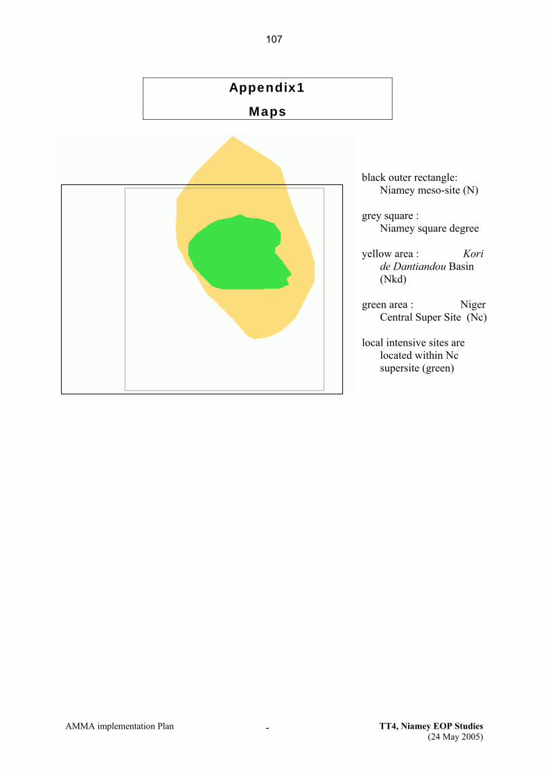
AMMA implementation Plan TT4, Niamey EOP Studies (24 May 2005)
-
Appendix1
Maps
black outer rectangle:
Niamey meso-site (N) grey square :
Niamey square degree yellow area : Kori
de Dantiandou Basin (Nkd)
green area : Niger
Central Super Site (Nc) local intensive sites are
located within Nc supersite (green)
107
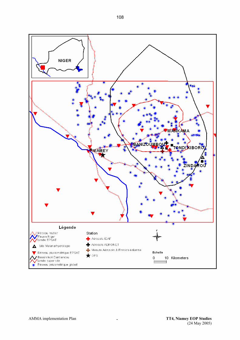
AMMA implementation Plan TT4, Niamey EOP Studies (24 May 2005)
-
108
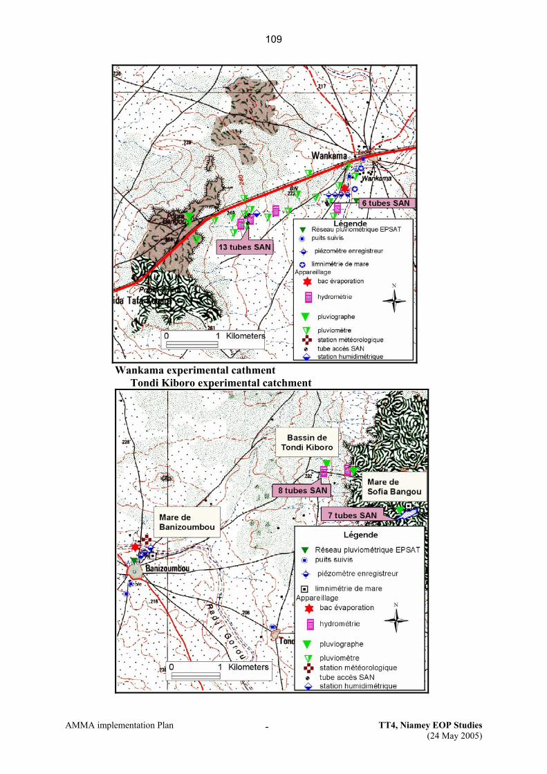
AMMA implementation Plan TT4, Niamey EOP Studies (24 May 2005)
-
Wankama experimental cathment
Tondi Kiboro experimental catchment
109

AMMA implementation Plan TT4, Niamey EOP Studies (24 May 2005)
-
Appendix2
List of TT4 instruments (Niamey Meso Site, EOP and LOP)
TT4 : French EOP/LOP Instruments
French EOP Instruments (EFx)
# Code PI Name E-Mail Address Instrument Platform EF18 CE.Rain_Nc Luc Descroix [email protected] 15 recording raingauge network Niamey SS central Nc EF19 CE.Run_Nc Luc Descroix [email protected] Network of 6 recording streamgauges Niamey SS central Nc EF20 CE.Gwat_Nc G. Favreau [email protected] Level recorders, 12 drilled boreholes Niamey meso site N EF21 CE.SW_Nc B. Cappelaere [email protected] 4 sites Watermark and TDR Niamey SS central Nc EF22 CE.SWsan_Nc Luc Descroix [email protected] Soil water neutron probe Niamey SS central Nc EF23 CE.Veget_Ncw Nicolas Boulain [email protected] Leaf index and gaz exchange meas.t Niamey-Wankama Ncw
French LOP Instruments (LFx)
# Code PI Name E-Mail Address Instrument Platform LF2 AL.Met_Nc Luc Descroix [email protected] Campbell Met. Station Banizoumbou Ncb LF17 CL.Rain_N Thierry Lebel [email protected] 30 recording raingauge network Niamey meso site N LF24 CL.Gwat_N G. Favreau [email protected] Level recorders in wells (aquifer) Niamey meso site N LF20 CE.Pond_Nc B. Cappelaere [email protected] 6 recording level in ponds network Niamey SS central Nc
Other Instruments implemented on the Niamey site, in the framework of other TTs
TT2a # Code PI Name E-Mail Address Instrument Location
EF8 AE.Flux_Ncw B. Cappelaere [email protected] 2 H2O/CO2 flux stations Niamey-Wankama NcwEE1 AE.Flux_Nc C. Lloyd [email protected] 2 HFS flux stations Niamey SS central Nc
TT2b # Code PI Name E-Mail Address Instrument Location
EF30 AE.Dust_ST Jean-Louis Rajot [email protected] Banizoumbou TEOM site Sahelian Transect LF26 CL.Depot_RW C. Galy-Lacaux [email protected] 5 stations IDAF (4 avec aethalomètre) Regional Window
TT1 # Code PI Name E-Mail Address Instrument Location
EF1 AE.GPS_1 O. Bock [email protected]; [email protected]
Niamey GPS station (in a set of 4). Niamey airport
110

AMMA implementation Plan TT4, Niamey EOP Studies (24 May 2005)
-
Appendix3
List of members of TT4 working groups
IP/API 1.2
IP 1.3
API 1.3
IP/API 2.3
IP/API 2.4
IP 3.1
IP 3.3
API 4.1.2
IP/API4.2.2
IP/API 4.2.3
IP/API 4.3
OVNI (F)
Descroix X X X Cappelaere X X X X X X X
Boulain (pd) X X X X X Rajot (p) X X X Lebel (p) X X X X
Massuel (d) X X X X X Ali (d) X X
Vischel (d) X Favreau (p) X X Baron (p) X X Lloyd (p) X X X X
Gignoux (p) X X Amani (p) X Zribi (p) X X
Timouk (p) X Bouin (p) X Bock (p) X
Galy-Lacaux (p)
X
Laurent JP (p) X X X Codes: (pd) = post-doctorate (d) = doctorate (p) = part-time (small fractions in most cases)
The local staff of working groups Health Satellite /
Radar Hydrology Aerosols GPS Soils,
Vegetation AgronomyEcosystems
WP 3-4, 2-3 Red :
leaders I. Jeanne André
NonguiermaM.
Adamou Dungall Laouali
Y. Nazoumou
Ali Mahamane
Issoufou Wata
M. Kalache B. Gérard L. Descroix Jean-Louis Rajot
André Nonguiera
ma
JMK. Ambouta
Seydou Traoré
JB. Duchemin
M. Kalache JB. Duchemin
I. Jeanne/ M. K.
EAMAC voir AD
Ichaou Aboubacar
Waziri Mato
Hamadou Djibo
I. Jeanne Charlotte Bailleul
Seydou Sanda I.
(IGNN) RD
I. Bouzou Ichaou Aboubacar
P. Gineste I. Bouzou Zibo Garba Hassimi I. Jeanne/ M. K.
Laouali Ibrahim
Y. Nazoumou
H. Adamou A.O. Manga
Djabi Bakary
B. Barmou-Batouré
Djabi Bakary
Y. Nazoumou
L. Descroix M. Amadou
Alfari Issoufou
B. Gérard B. Gérard B. Gérard
Job Andigué
A. Amani
O. Faran Maïga
P. Gineste
111
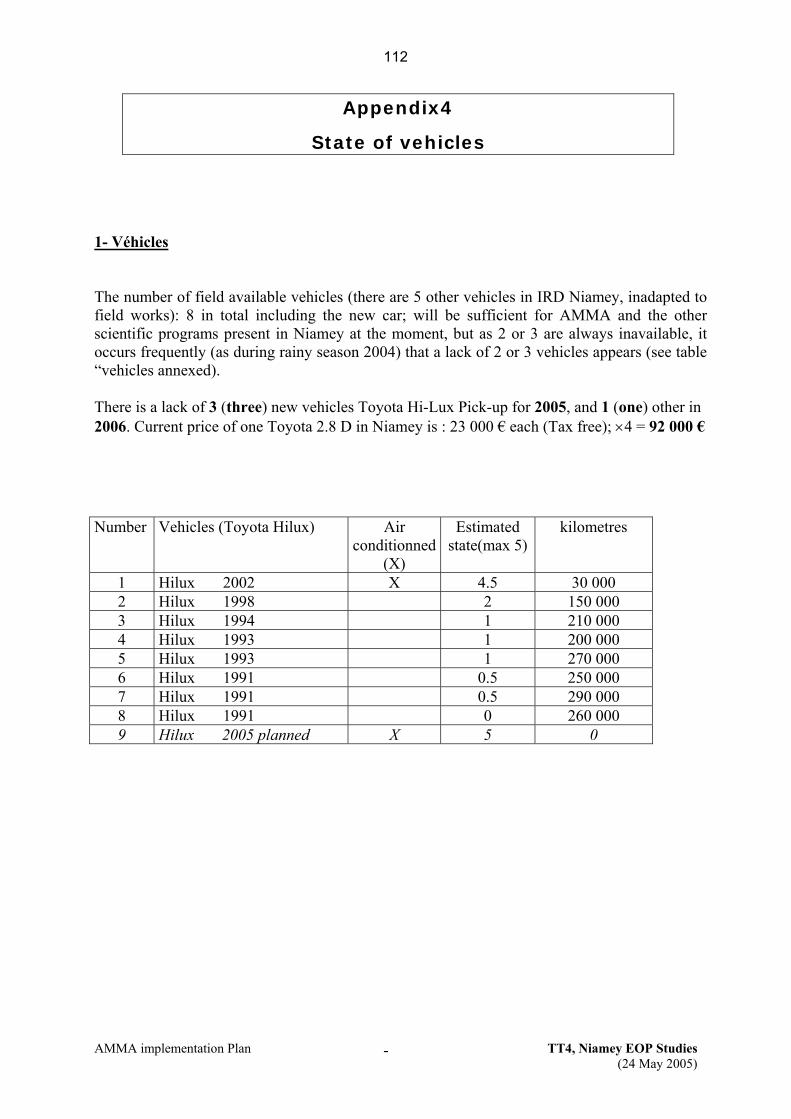
AMMA implementation Plan TT4, Niamey EOP Studies (24 May 2005)
-
Appendix4
State of vehicles
1- Véhicles The number of field available vehicles (there are 5 other vehicles in IRD Niamey, inadapted to field works): 8 in total including the new car; will be sufficient for AMMA and the other scientific programs present in Niamey at the moment, but as 2 or 3 are always inavailable, it occurs frequently (as during rainy season 2004) that a lack of 2 or 3 vehicles appears (see table “vehicles annexed). There is a lack of 3 (three) new vehicles Toyota Hi-Lux Pick-up for 2005, and 1 (one) other in 2006. Current price of one Toyota 2.8 D in Niamey is : 23 000 € each (Tax free); ×4 = 92 000 €
Number Vehicles (Toyota Hilux) Air
conditionned(X)
Estimated state(max 5)
kilometres
1 Hilux 2002 X 4.5 30 000 2 Hilux 1998 2 150 000 3 Hilux 1994 1 210 000 4 Hilux 1993 1 200 000 5 Hilux 1993 1 270 000 6 Hilux 1991 0.5 250 000 7 Hilux 1991 0.5 290 000 8 Hilux 1991 0 260 000 9 Hilux 2005 planned X 5 0
112

AMMA implementation Plan TT4, Niamey EOP Studies (24 May 2005)
--
Appendix5 Planning of instrument implementation
2004 2008exist 1 2 3 4 5 6 7 8 9 10 11 12 1 2 3 4 5 6 7 8 9 10 11 12 1 2 3 4 5 6 7 8 9 10 11 12 contd.
level recorders on ponds1 H2O flux station
15 recording raingauge network
Network of 6 recording streamgauges
Level recorders, 12 drilled boreholes
4 sites Watermark and TDR
Soil water neutron probe
Li COR LAI-2000 and Li COR 6400
Banizoumbou TEOM site
Campbell Met. Station
30 recording raingauge network
Level recorders in wells (aquifer)
5 stations IDAF (4 avec aethalomètre)
GPS Niamey
2005 2006 2007
113

AMMA implementation Plan TT4, Niamey EOP Studies (24 May 2005)
-
Appendix 6
Planning of commissions and vehicles 2005 See attached excel table
114

AMMA implementation Plan TT5, Ouémé EOP Studies
TT5 – EOP integrative studies on the Ouémé meso-scale site
Updated April 7, 2005
1. Scientific justification and objectives The aim of this document is to present the scientific consistency of the observing strategy on the Ouémé meso-scale site in Benin, with respect to the objectives of AMMA detailed on the AMMA-IP and AMMA-API documents, to coordinate instrument deployment and address the associated logistic issues. These aspects are extended to the Cotonou site. Some aspects are also relevant to Task team 1 (Radio-soundings), 2 (Fluxes), 6 (oceanic campaigns) and 7, 8, 9 (SOP). Most of the instruments are deployed on the Upper-Ouémé catchment, (14600 km2, centred on 9,5°N, 2°E), with average yearly rainfall of 1200 mm (one single season). These instruments document processes in the soudano-sahelian domain of the AMMA experiment.
2. Observing strategy a. Overall strategy
The observing strategy on the Ouémé meso-scale site is based on a multi-scale approach, associating LOP, EOP and some of the SOP instruments. Even if this TT is limited to EOP, some SOP instruments are considered in the observation strategy, when they complement LOP/EOP set-up. The observing strategy has been conceived for the documentation of: i) climatic forcing and atmospheric parameters, ii) the continental water cycle, from local to meso scale, and feed backs iii) aerosol and atmospheric chemistry processes.
Climatic forcing and atmospheric parameters,
Spatial and temporal variability of rainfall fields is documented on the long term by a network of 46 automatic raingauges (CL.Rain_O and CL.Rain_Od 1) operating since 1997 as part of the LOP component of AMMA (labelled as the AMMA-CATCH ORE 2). In EOP and SOP periods, these data will be of primary importance for most of the instruments, as a
1 In this section the instrument code is mentioned in beside the instrument name for clarity. Refer to Appendix 1 for instrument list and nomenclature. 2 Observatoire de Recherche en Environnement, French Ministry of Research.
115
AMMA implementation Plan TT5, Ouémé EOP Studies
quantification of rain inputs to the hydrologic and vegetation systems, and for aerosol deposition and surface emissions. This network will be improved in EOP and SOP periods with the deployment of two Doppler, polarized meteorological radars: Xport (AE.RadX_O) and RONSARD (AE.Ronsard_Or, SOP). They will provide essential high resolution, 3D description of rainfall events, and contribute to a better estimations of rainfall fields to force hydrological models, as well as to link storm-scale processes to larger dynamical signatures. They are associated with one disdrometer (AE.Dsd_Or), one optical spectro-pluviometer (AE.OSP_Od) and one bi-static receptor (AE.BIST_RADAR). To validate radar rainfall estimations, two raingauge lines (eastwards and north-eastwards), and a high-resolution target made of a series of locally denser raingauges located 30-km east of Djougou have been designed (see Appendix 1.2). The Djougou site (near the Xport Radar) has been chosen for other instruments such as a VHF Profiler (AE.VHF_O), a GPS (AE.GPS_1), a lidar-ceilometer (AE.CT25K), a micro-wave temperature and humidity profiler (AE.PROF_T), a meteorological station (AE.Met_Od) and a micro-rain radar (AE.RADK_T) to help characterizing the state of the atmospheric column (wind, water vapour profile, integrated water vapour content, cloud bottom height,...), see Appendix 1.2. The Beninese site contributes, for some instruments, to regional observations systems: the GPS in Djougou is part of a network of two meridian transects: Djougou-Niamey-Gao, operated during the EOP, and Tamale-Ouagadougou-Tombouctou, operated only during the SOP (May-Sept 2006). This network provides continuous (1-hourly) monitoring of total column water vapour in the atmosphere, which is one of the key components of the water cycle. As well, the Parakou and Cotonou radio-sounding (AE.RS_Q1), in EOP and SOP periods, are part of a West African RS network (see TT 1 “Radiosoundings” document), and complement the documentation of the state of the atmosphere over Ouémé and Benin (Appendix 1.3). Specifically these stations are two of the five RS stations of the quadrilateral window stretching over Nigeria, Benin, Togo, Ghana and Niger, and documenting large scale atmospheric forcing, to help constraining analyses and re-analyses. This quadrilateral is a pilot window, including the upper Ouémé watershed, for integrated surface-atmosphere water budget studies (WP1.2 of AMMA-IP and AMMA-API). The ozone radio-sounding in Cotonou (AE.RSO3_O), documents ozone concentration profile up to the troposphere, and contribute to the studies of ozone dynamics in tropical areas. These instruments and related issues are handled by Task Team 1 (Radio-soundings and GPS). Manque : Justification scientifique des moulins à champ et du BVC au Bénin ici
Continental water cycle and feed backs Observation of the continental water cycle is based on a multi-scale (spatial and temporal) approach, associating local sites (transects), super-sites (Donga Watershed) and meso-scale watershed (upper Ouémé basin), and combines long-term (LOP) and enhanced (EOP) observation periods. Local scale observations are dedicated to elementary processes studies. Detailed measurements of the water cycle components will be performed on three transects (or catena)
116
AMMA implementation Plan TT5, Ouémé EOP Studies
representative of the major vegetation cover of the area (fallow, bush savannah and forest) (see Appendix 1.1). These sites include soil water monitoring stations (CE.SW_Odc), piezometers (CE.GWat_Odc), runoff on small gullies (CE.Run_Odc), vegetation monitoring (CE.Veg_Odc) and fluxes stations (AE.Flux_Odc). The three fluxes stations are also part of a regional network including a south site in Ghana, three stations in the Niger Site, and three others in the Gourma site. As well, superficial geophysical surveys with electric soundings (CC.Geophy_Odc) or Protons Magnetic Resonance (CC.RMP_Odc) will document the geometry of the sub-surface reservoir, and the piezometric level fluctuations in relation with the river discharge. Chemical composition of surface, subsurface, and ground water on transects will be analysed (CE.WChem_Odc), and compared to chemical composition of water in river to determine water origins, flow paths and transfer time. A particular effort is made on the observation of the feed-back term of the water cycle (evapo-transpiration), with the deployment of 1 flux station (AE.Flux_Odc) on each transect (one additional is associated to the mobile laboratory) and one infra-red scintillometer (CC.Scintill_Od) on the fallow site. The strategy is to locally document the fluxes dynamic in relation with the evolution of vegetation and the hydric resource, and to find spatial integration method on a limited area using the scintillometer. Larger up-scaling of fluxes is foreseen using satellite-derived images, and -if relevant- airborne fluxes measurements during SOP. The local-scale observation strategy is adapted to the super-site scale (Donga catchment), with the documentation river runoff (CL.Run_Od), water table levels (CL.GWat_Od) and water chemical composition in wells, boreholes and river (CL.GWat_Od). These data, associated to knowledge and processes captured at local scale, will be used in a hydrologic modelling framework to test and validate water cycle processes, characterize the water cycle compartments and quantify the water balance components, at intra-seasonal to inter-annual time scales. The Aguima catchment, located south of the upper-Ouémé meso-scale site (see Appendix 1.3), is been intensively surveyed by the German project IMPETUS3, to document meteorological, hydrologic and environmental processes. Collaborations and data sharing agreements have been developed with this project, and this site can be considered as a secondary super-site, on a geologically contrasted area, as compared to the Donga basin. The previous observation strategy is also transposed at the meso-scale, with observations of river flow on 20 stations (CL.Run_O), water table levels (CL.GWat_O), and chemical composition of water in rivers (CE.WatChem_O). As the large basin integrates contributions from various geological areas and spatial variability of rainfall, the chemical signature of water helps understanding the flow paths and transfer time at the meso-scale. Based on processes identified at the super-site scale, meso-scale hydrologic data combined with satellite-derived vegetation maps (land cover, LAI dynamics) will be used in a modelling framework to validate the continental water cycle processes and calculate the water budget components. These efforts contribute to water budget studies (WP 1.2).
Aerosol and atmospheric chemistry processes 3 IMPETUS is not formally associated with AMMA, but a few of IMPETUS teams are also involved in the AMMA European Project.
117

AMMA implementation Plan TT5, Ouémé EOP Studies
As a component of the aerosol and atmospheric chemistry part of the AMMA experiment, a series of instruments (formerly part of the mobile laboratory of Laboratoire d’Aérologie, Toulouse, France) will be deployed as from march 2005. For convenience they are all included in the unique instrument AE.Van_Od. They will be deployed in the Nangatchori site, 10 km SE from Djougou (see Appendix 1.2). The objectives are: - to gather a precise documentation on biogenic emissions (processes and seasonal variability). This will be done through the development of a methodology allowing for a better quantification of the different types of emissions. Modules of biogenic emissions and deposition of reactive trace gases (NOx, COV, O3) will be developed and validated directly through field experiments. These modules will eventually be integrated in chemistry-climate interaction models focused on the West-African region. - to build and emission inventories of biogenic sources (NOx, COV), biomass combustions (savannah and domestic fires) and urban sources with a spatial and temporal resolution adapted to the chemistry-climate models - to link existing networks and observatories with ground-based data obtained in Djougou to study inter-annual and seasonal variations of combustion tracers (BC, CO) and aerosols optical properties. Later, this work will be used to build a 3D data base over two years for assimilation and validation in regional and global models. These models will help to conduct regional studies (like deposition-transport of aerosol impact and processes-Meso-NH-Chimie, and seasonal scale studies- RegCM), as well as large scale studies (TM4, MOCAGE). Models will be used to constrain emission inventories and study the species redistribution influenced by the main dynamical phenomena (convection, transport) associated to the monsoon, and study their impact on the chemistry and climate. To document dry and wet deposition, as well as aerosol composition, an IDAF station (CL.Depot_RW) and dust impactors (AS.Dust_Od), will be deployed on the Nangatchori site. Incidentally, chemical analyses of rainfall water produced for IDAF studies will be also used to detect noise in chemical tracing of flow paths (see hydrology section above) due to unexpected atmospheric inputs in river water. This setup is complemented by a sun photometer (CL.Photometer) of the PHOTON-AERONET network, deployed 7 km N from Djougou since January 2003. Together with AMMA-CATCH, IDAF and PHOTON-AERONET (labelled as OREs) observing systems are part of the LOP component of AMMA.
b. Modelling and satellite observations These instruments provide data for calibration, validation and data assimilation in models, as well as validation data for satellite products (vegetation cover , fluxes). Refer to AMMA documents for more details. A particular need concerns the estimation of large scale fluxes (evapotranspiration) from local tower and scintillometer measurements, and satellite images, using models.
c. List of sites, instruments and relevant maps Site maps and LOP/EOP instrument location are given in Appendix 1
118

AMMA implementation Plan TT5, Ouémé EOP Studies
Local scale A1.1, super-site A1.2, meso-scale site A1.3, and SOP instruments are mentioned for information on the meso-scale map in A1.4. The full list of instruments is provided in Appendix 2. Some SOP instruments are considered, when they complement the LOP/EOP and campaigns set-up (ex. RONSARD Radar).
d. Priorities Most of the instruments cited in this document have secured funding from either French-API or IP (or other sources). There is therefore no need to attribute priorities among them, except in case of competition for funds. Some instruments have unsecured funding:
• Field-Mills (AS.Field_Mills_O) • Radar ST (AE.VHF_O) Updated information is needed on funds availability
Some instruments, of significant interest, are not funded:
• Geophysical Surveys (CC.Geophy_O) Priority 1 • Magnetic Proton Resonance (CC.RMP_O) Priority 2
Concerning the risk issue, no particular aspect is to be mentioned, except unexpected delays in material shipping, which may delay field deployment. These risks are normally anticipated by instruments PI’s by early shipping. The political situation in Benin has been very stable for years. Next presidential elections will be held in March 2006. In principle, this political event gives no cause for concern for the course of the experiment.
3. Deployment Deployment, operation and maintenance of these instruments imply a number of logistical constraints, detailed below.
a. Planning
The periods of deployment of the various instruments is foreseen following the planning given in Table 1, next page. The set-up, operation and maintenance of these instruments require regular mission in the field, either for people permanently in Benin (IRD teams and Beninese partners) or people coming in mission for a limited stay. A tentative planning of missions is presented in Table 2 for 2005 and 2006.
119

AMMA implementation Plan T5, Oueme EOP Studies 6
Table 2a. Planning of instrument deployment
2004 2008Sheet # Inst. Code Description exist 1 2 3 4 5 6 7 8 9 10 11 12 1 2 3 4 5 6 7 8 9 10 11 12 1 2 3 4 5 6 7 8 9 10 11 12 contd.
EF2 AE.RadX_O Radar XportEF3 AE.Dsd_ Or Disdrometer
- AS.Ronsard_Og Radar Ronsard? AS.BIST_RADAR Bi-static radar
EF4 AE.OSP_Od Opt, Spectro PluviometerEF5 AE.VHF_O Radar ST
? AE.CT25K Lidar Ceilometer? AE.RADK_T Micro Rain Radar? AE.PROF_T Microwave Profiler- AS.Field_Mills_O Field mills (5 stations)
LF18 CL.Rain_0 30 recording raingaugesLF19 CL.Rain_Od 18 recording raingaugesLF21 CL.Run_O 14 recording streamgaugeLF22 CL.Run_Od 6 recording streamgaugesLF23 CL.ADCP_O ADCPEF24 CE.Run_Odc runoff on 3 transects: 3 totalLF25 CL.Gwat_Od 21 surveyed wellsEF27 CE.Gwat_Odc Network of 27 piezometersEF25 CE.W Chem_O surf/ground water chem. Anal.EF26 CE.W Chem_Od surf/ground water chem. Anal.CF1 CC.Geophy_Odc geophysical surveysCF? CC.RMP_Odc RMP surveysLF3 AL.Met_Od Meteo Station Campbell
EF28 CE.SW _Odc 9 SW stations EF29 CE.Veg_Odc vegetation surveys EF33 AE.VAN_Od Labo Van + aérodynamique
? AS.Dust_Od Atm. depositionLF26 CL.Depot_RW 1 IDAF station
? CL.Photometer photometerEE9 AE.Flux_Od 2 SH and 2 H2O flux stationsEF9 AE.Flux_Odc 1 H2O flux stationCF2 CC.scintil_Od Scintillometer
EF31 AE.RSO3_Od Ozone radiosoundingsEF1 AE.GPS_1 1 GPS station in Djougou
? AS.GPS_1 1 GPS station in DjougouEE1 AE.RS_Q1 2 RS Stations
- AS.BVC_T2 Ballon Volume Constant
2005 2006 2007
Pertinence de AE.Flux_Od et A.Flux.Odc dans le tab ?
120

AMMA implementation Plan T5, Oueme EOP Studies 7
Table 2a. Planning of missions 2005
EO P1 2 3 4 1 2 3 4 1 2 3 4 1 2 3 4 1 2 3 4 1 2 3 4 1 2 3 4 1 2 3 4 1 2 3 4 1 2 3 4 1 2 3 4 1 2 3 4
EF2, EF3 AE.RadX_O , AE.Dsd_ Or Radar Xport 2P
EF4 AE.OSP.O Spectro-p luvio- AS.Ronsard_O g Radar Ronsard
AS.B ist_radar bi-statiqueEF5 AE.VHF_O Radar ST 1P- AS.F ield_Mill_O French F ie ld m ills (5)
AE.RADK_T Micro Rain RadarAE.CT25K Lidar Ceilom eterAE.PRO F_T Microwave Profiler
LF18, LF 19 CL.Rain_O , CL.Rain_O d Raingauge network (*)
LF21, LF22, LF23, EF24
CL.Run_O , CL.Run_O , CL.Run_O dc, CL.ADCP O
River runoff network (*)
LF25, EF27 CL.Gwat_Od, CE.G wat_O dc Piezom eter network (*)
EF25, EF26 CE.W Chem _O, CE.W Chem _Od
surf/ground water chem . Anal.
LF3 AL.Met_Od Meteo Station (*)EF28 CE.SW _Odc Soil W ater sta tions (*)CF1 C_geophy_O dc Geophysical surveys
EF29 CE.Veg_O dc Veget. surveys on transects
EF33 AE.VAN_Od Mobile Lab (**) 1P 1PLF26 CL.Depot_RW 1 IDAF station (**)
AS.Dust_O Atm . Deposition- CL.Photom eter sun photom eter (*)
EE9, EF9 AE.F lux_Od, AE.F lux_Odc Flux sta tions 1P/8D
CF2 CC.scintil_O d Scintillom eter 1PEF31 AE.RSO 3_Od Ozone Radio-sounding EF1 AE.GPS_1 1 GPS (D jougou) 2P 2PEE1 AE.RS_Q1 2 RS Stations- AS.BVC_T2 Ballon Volum e Constant
fie ld m ission for people perm anently in Cotonou to be detailedfie ld m ission for people in m ission in Benin (P : # people ; D # days)
(*) (**) instrum ents vis ited sim ultaneously
1P
2P
2P P/15D+1P/301P
1P
august sept. october nov.m ai june ju lyjanuary february m arch april dec.
121

AMMA implementation Plan TT5, Oueme EOP Studies 8
Table 2b. Planning of missions 2006
SOP1 2 3 4 1 2 3 4 1 2 3 4 1 2 3 4 1 2 3 4 1 2 3 4 1 2 3 4 1 2 3 4 1 2 3 4 1 2 3 4 1 2 3 4 1 2 3 4
EF2, EF3 AE.RadX_O, AE.Dsd_ Or Radar Xport
EF4 AE.OSP_O Spectro pluvio- AS.Ronsard_Og Radar Ronsard+bi-static 4P 2 teams (2x 2P)/120 D 4PEF5 AE.VHF_O Radar ST
AE.CT25K Lidar ceilometerAE.RADK_T micro rain radarAE.PROF_T microwave profiler
- AS.Field_mill.O French Field Mills (5) 2P/90D
LF18, LF 19 CL.Rain_0, CL.Rain_0d Raingauge network (*)
LF21, LF22, LF23, EF24
CL.Run_O, CL.Run_O, CL.Run_Odc, CL.ADCP O
River runoff network (*)
LF25, EF27 CL.Gwat_Od, CE.Gwat_Odc Piezometer network (*)
EF25, EF26 CE.W Chem_O, CE.W Chem_Od
surf/ground water chem. Anal.
LF3 AL.Met_Od Meteo Station (*)EF28 CE.SW _Odc Soil W ater stations (*)CF1 C_geophy_Odc Geophysical surveys
EF29 CE.Veg_Odc Vegetation surveys on transects
EF33 AE.VAN_Od Mobile Lab (**)LF26 CL.Depot_RW 1 IDAF station (**)? AS.Dust_Od Atmosph. deposition 6P 4P- CL.Photometer sun photometer (*)
EE9, EF9 AE.Flux_Od, AE.Flux_Odc Flux stations
CF2 CC.scintil_Od ScintillometerEF31 AE.RSO3_Od Ozone Radio-sounding EF1 AE.GPS_1 1 GPS station (Djougou) 2P 2PEE1 AE.RS_Q1 2 RS Stations- AS.BVC_T2 Ballon Volume Constant 1P
field mission for people permanently in Cotonou to be detailedfield mission for people in mission in Benin (P: # people ; D # days)
2P
julyjanuary february march april nov.
1P
mai june
(*) (**) instruments visited simultaneously
2P/15D+1P/30D 1P
1P
dec.
1P
august sept. october
122

AMMA implementation Plan TT5, Oueme EOP Studies
b. Logistical considerations The deployment and operation programs shown in the previous tables impose a number of logistical constraints, concerning vehicles, human resources, buildings and communications.
Vehicles IRD in Cotonou dispose of a pool of 5 4-wheel-drive vehicles, including two bought in 2004; 2 new will be available mid-2005, and 2 additional “urban” cars, amongst which one is dedicated to people in mission. 4WD vehicles are primarily dedicated to IRD teams in Benin (not all involved in AMMA), but also to AMMA teams depending on availability. In case of extra needs, renting solutions are possible, with a reliable institution in Cotonou offering good conditions.
Infrastructures
Offices in Cotonou AMMA teams are housed by Beninese partners in buildings of Direction de la Météorologie Nationale, near the airport (radar and atmospheric chemistry teams), and Direction General de l’Hydraulique (hydrology teams), in a neighbourhood of 5 km. IRD will provide extra housing capacities for AMMA teams in IRD headquarter building: one meeting room; one secured storage area; one office for logistic support/Operation Centre; one office for teams in mission and one office for the Benin AMMA National Committee, all equipped with usual telecommunication facilities including full internet. One issue is not solved yet, due to lack of funding: Waterproofness of the roof of the DNM building must be undertaken. Estimated cost is 1500 € (not funded).
Housing in Djougou during field missions Housing in Djougou for people in mission in the field is possible in the existing IRD house (basic facilities), depending on availabilities, or in hotels. Housing in remote sites (Copargo, RONSARD Radar) has not been considered here, and must be addressed specifically. The Task Team coordination can provide help in that concern.
Human resources Permanent staff in Cotonou in March 2005 is 13 person (IRD) and 3 students (1PhD, 2 master), and 2 permanent people (IRD) must arrive before September 2005, as well as new students. EOP/LOP logistics is taken in charge by M. Jean-Michel Bouchez, IRD engineer in Cotonou. A secretary (freight, customs, hotel and travel booking, ..) will be hired 4, and depending on the configuration of the Cotonou Operation Centre, an additional person will be recruited, with good technical and scientific skills as well as organization capabilities, in order to
4 Funds must be identified
123

AMMA implementation Plan TT5, Oueme EOP Studies
support all the teams in logistic tasks (technical support, relations with authorities, etc ). This position if funded by the European project AMMA-IP.
Technical maintenance in the field A number of teams have not planed to have permanent staff in the field to watch their instrument(s). Considering that breakdowns or incidents are very likely events, due to the particular context (frequent electric power cuts, fuel penuries, lightning…), the Task Team coordination strongly suggest that one or two technician(s) could be locally contracted, trained, and then stay on the site and permanently watch and maintain a series of instruments during the whole operation period (vehicles such as motorcycles should be provided). They could warn teams in Cotonou in case of incident with cellular phones. Decisions on this point must be taken by instruments PI’s (EOP and SOP), with the support of TT5 coordination. Rough costs estimates: Gross annual salary 3500€; motorcycle 750 €
Internet Communications This issue has to be coordinated with SOP TT and Operation Centre, for needs and funding
Cotonou sites
All the buildings where AMMA people will stay in Cotonou, except the DMN5 are equipped with a full-internet connection (satellite connection), with a remote administration by Direction des Systèmes d’Information (DSI) at IRD-Montpellier (France). Internet equipment for the DMN has been requested to IRD, and the final agreement is awaited.
Field sites Internet Communication needs in the fields concerns the sites of Djougou (Xport Radar, GPS, VHF), Copargo (Ronsard Radar), Nangantchori (atmospheric chemistry and aerosols), and Nalohou (scintillometer). It is essential for coordination of aircraft flight (aircraft base and main operation center –OC- in Niamey) that near-real-time quick-looks of RONSARD data (image) be available for the Niamey OC. As well, transmission of Xport images to Cotonou is essential for near-real-time analyses. The other instruments settled next to Xport will also benefit from the link for data transmission. Other communication need is identified for the Parakou RS station, and a solution using classical telephone network and modem will be implemented (RS task Team). The Task Team core group has made an inventory of all the possible technical solutions available in Benin, with a rough cost estimate (see appendix 4). The final choice has to be made when the precise technical requirements will be established, and the funding issue solved. This has to be done in strong coordination with SOP Task Teams and Principal Operation Centre coordination. A list of available technical solutions, with rough costs estimates, is given in Appendix 4.
5 Direction de la Métérologie Nationale
124
AMMA implementation Plan TT5, Oueme EOP Studies
4. Partnership a) Field observations
Partnerships for field observation mainly involve:
• Direction Générale de l’Hydraulique/Service de l’Hydrologie : meso-scale runoff-data on the Ouémé and Donga basin
• Direction de la Météorologie Nationale : Radio-soundings (Cotonou and Parakou), RS Ozone (Cotonou), Xport Radar (test phase in Cotonou)
• Département de Physique, Faculté des Sciences et Techniques (FAST), Université d’Abomey Calavi (UAC): Radars, atmospheric physics
• Centre de Recherches Hydrographiques et Océanographiques Béninois (CRHOB) : oceanographic campaigns
• IMPETUS, German integrated project with shared field activities on water cycle observations (monitoring of the Aguima watershed, included in the upper-Oueme basin).
b) Training program • Students from UAC (FAST, Faculté des Sciences Agronomiques : 2 master, 1PhD in
2005 • technicians from DMN :RS and RS-ozone training, and radar acquisitions.
5. Organisation of the TT.
a. Leaders, core group Task team leaders are : Christophe PEUGEOT [email protected] Sylvie GALLE [email protected] The Core Group members are : Jean-Michel BOUCHEZ [email protected] EOP Logistics Bernard BOURLES [email protected] TT oceanographic. Campaigns Frédéric CAZENAVE [email protected] Telecommunication resources Marielle GOSSET [email protected] radar representative Serge JANICOT [email protected] TT Radiosoundings representative Cathy LIOUSSE [email protected] aerosols/chemistry representative Colin LLOYD [email protected] TT Fluxes representative Alain PROTAT [email protected] TT9 Representative Luc SEGUIS [email protected] Donga coordination Dominique SERÇA [email protected] Aerosols/chemistry representative
The full list of TT member is given in Appendix 3
125

AMMA implementation Plan TT5, Oueme EOP Studies
b. Internal coordination Diffusion of information is made by email using the member list in appendix 3. To help local organization, the following procedure is proposed for missions to Benin : • 3 months prior mission, preliminary information must be provided to TT
coordinators (period, duration, field trip, ..) • detailed information on mission must be transmitted 1 month prior arrival (dates,
housing, specific needs...) The site coordination could provide people with technical support and facilities, depending on requests and availabilities.
c. How are handled requests for new instruments ?
All requests are received by the TT coordinators, and are transmitted to the relevant TT members. Request for new instruments must be transmitted at least 6 month prior installation, with detailed information on instrument relevance to AMMA scientific objectives, integration in the existing implementation plan, local partnership, technical characteristics, logistic needs, technical supports. Instrument and logistic sheets must be provided. Then the information procedure proposed for missions (previous section) must be applied
d. External diffusion of the information and reporting External diffusion of the information and reporting should follow a procedure common to all the task teams. This procedure, to be defined,should involve mailing lists and web pages support.
6. Coordination with other TTs Coordination with other task teams is foreseen through diffusion of information (email), and meetings of leaders outside IP or API meetings (no marginal travel costs). The leaders of the TT in inter-relation with TT5 are part of the core group, namely B. Bourles (oceano. campaigns), S. Janicot (RS), C. Lloyd (Fluxes). Coordination with SOP TT must be clarified, one the one hand for aircraft operation (flight plan coordination), and on the other hand for Ground-SOP activities, to avoid overlapping (RONSARD relevant to SOP TT and this one, RS relevant to EOP and SOP TT depending on RS frequencies...). Coordination with LOP Support Team remains unclear. For TT 5, IDAF and PHOTON Pis are members of the TT, as well LOP/Ouémé coordinators.
7. Ancillary information: reference, logistic forms, site document
126
AMMA implementation Plan TT5, Oueme EOP Studies
Appendix1
Maps
127
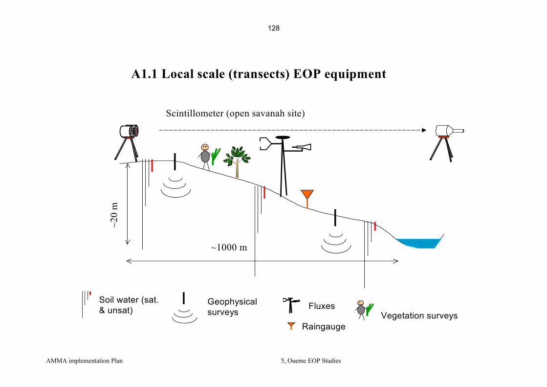
AMMA implementation Plan TT5, Oueme EOP Studies
A1.1 Local scale (transects) EOP equipment
Soil water (sat. & unsat)
Scintillometer (open savanah site)
~1000 m
~20
m
Fluxes
RaingaugeVegetation surveys
Geophysical surveys
128

AMMA implementation Plan TT5, Oueme EOP Studies
km0 5 10 15 20
Automatic piezometer
Daily piezometer
Rain recorder
Limnigraph
Rain bucket
Meteo
Transects (w. Fluxes)
Radar
raingages lines
Photometer
GPS
VAN and assoc. Instr.+ IDAF
1.5 1.6 1.7 1.8 1.9 2
9.6
9.7
9.8
9.9
Djougou
Kopargo
Radar raingages"target"
Radar VHF
Radar X-PortDisdro. +spectro-pluv.
Micro-rain radar
Lidar ceilometer
Profiler
A1.2 Donga super-site LOP/EOP equipment
129

AMMA implementation Plan TT5, Oueme EOP Studies
A1.3 Meso-scale Ouémé site LOP/EOP equipment
1 2 3 46
8
10
12
km0 10 20 30 40 50
Cotonou
Parakou
Location of the Upper Ouémé Valley in Benin
Raingage
Meteo
River flow stationRecording and dailyPiezometers
Aguima(IMPETUS Project)
Donga super-site
1.5 2 2.5
9
9.5
10
Flux station
Radiosounding
Parakou
Djougou
130

AMMA implementation Plan TT5, Oueme EOP Studies
A1.4 Meso-scale Ouémé site SOP equipment
1 2 3 46
8
10
12
km0 10 20 30 40 50
Cotonou
Parakou
Location of the Upper Ouémé Valley in Benin
Aguima(IMPETUS Project)
Donga super-site
1.5 2 2.5
9
9.5
10
Parakou
Djougou
Constant VolumeBalloon
Field Mills (French)
KopargoBi-static
RONSARD
Radars
Dust deposition
131

AMMA implementation Plan TT5, Oueme EOP Studies
Appendix2
List of TT5 instruments Nomenclature: Form #: XY# with X=L(LOP)/E(EOP)/S(SOP)/C(Campaign) ; Y=F(French)/E(European) instrument Instrument code XY.name_O(d)(c): X=A(Atmosphere)/C(Continent)/O(Ocean) ; Y=L/E/S/C, idem form # ; O(d)(c)=O(Ouémé site)/(d)(Donga supersite)/(c)(catena=local)
Period Form # Code PI Name E-Mail Address Instrument Platform
EOP EF2 AE.RadX_O Marielle Gosset [email protected] X Band Hydrometeo.. Radar Djougou EOP EF3 AE.Dsd_ Or Marielle Gosset [email protected] Disdro Parsival Djougou EOP EF4 AE.OSP_Od Laurent Barthès [email protected] Optical Spectro Pluviometer Dakar then Djougou EOP EF5 AE.VHF_O Bernard Campistron [email protected] VHF profiler Djougou EOP EF9 AE.Flux_Odc Sylvie Galle [email protected] 1 H2O flux station Ouémé-Donga EOP EF24 CE.Run_Odc Luc Seguis [email protected] 1 seuil jaugeur on 3 transects: 3 total Donga, transects EOP EF25 CE.WChem_O Christophe Peugeot [email protected] Chemical Analysis: surf/ground water Ouémé EOP EF26 CE.WChem_Od Luc Seguis [email protected] Chemical Analysis: surf/ground water Ouémé-Donga EOP EF27 CE.Gwat_Odc Luc Seguis [email protected] Network of 27 piezo in drilled wells Donga, transects EOP EF28 CE.SW_Odc Sylvie Galle [email protected] 3 stations on 4 transects: 12 in total Donga, transects EOP EF29 CE.Veg_Odc Josiane Seghieri [email protected] Vegetation surveys (biomass, phenology, LAI) Donga, transects EOP EF33 AE.VAN_Od Dominique Serça [email protected] Labo Van + aérodynamique Djougou
EOP EE ? AE.CT25K Suzanne Crewell [email protected] Lidar Ceilometer CT75K Djougou
EOP EE ? AE.RADK_T Suzanne Crewell [email protected] Micro Rain Radar Djougou
EOP EE ? AE.PROF_T Suzanne Crewell [email protected] Microwave temp. and humidity profiler Djougou
Campaign CF1 CC.geophy_Odc Henri Robain [email protected] Résistivimètres SYSCAL Pro et R2 Donga, transects Campaign CF2 CC.scintil_Od Jean-Martial Cohard [email protected] Scintillomètre flux de chaleur sensible Donga, transects Campaign CF? CC.RMP_Od Jean-Michel Vouillamoz [email protected] Résonnance magnétique des protons Donga, transects
LOP LF3 AL.Met_Od Sylvie Galle [email protected] Station Météo Campbell Djougou (Ouémé) LOP LF18 CL.Rain_O Christian Depraetere [email protected] 30 recording raingauge network Ouémé meso site LOP LF19 CL.Rain_Od Luc Le Barbé [email protected] Network of 18 recording raingauges Ouémé-Donga LOP LF21 CL.Run_O Christophe Peugeot [email protected] 14 recording streamgauge network Ouémé meso site
132

AMMA implementation Plan TT5, Oueme EOP Studies
Period Form # Code PI Name E-Mail Address Instrument Platform LOP LF22 CL.Run_Od Luc Seguis [email protected] Network of 6 recording streamgauges Ouémé-Donga LOP LF23 CL.ADCP_O Christophe Peugeot [email protected] Accoustic Doppler Current Profiler Ouémé LOP LF25 CL.Gwat_Od Luc Seguis [email protected] 21 village sites (11 recorders) Ouémé-Donga LOP LF26 CL.Depot_RW Corinne Galy-Lacaux [email protected] 5 stations IDAF (4 avec aethalomètre) Regional Window LOP - CL.Gwat_O Luc Séguis [email protected] 127 puits à lecture annuelle Ouémé LOP - CL.Photometer Philippe Goloub [email protected] ORE PHOTON (aérosols) Regional Window
Instruments relevant to other Task teams (p.m.)
Instruments deployed on the Ouémé watershed
Period Form # Code PI Name E-Mail Address Instrument Platform Task Team EOP EE9 AE.Flux_Od Colin Lloyd [email protected] 2 SH and 2 H2O flux stations TT2 (Fluxes)
EOP EF1 AE.GPS_1 Marie-Noëlle Bouin, Olivier Bock
[email protected]; [email protected] 4 GPS stations regional window
including 1 Djougou TT1 (Radio-sounding)
EOP EE1 AE.RS_Q1 Serge Janicot [email protected] 5 RS Stations Quadrilateral including Cotonou & Parakou
TT1 (Radio-sounding)
SOP ? AS.Ronsard_Og Georges Scialom [email protected] Radar Ronsard Kopargo SOP ground
SOP AS.Bist_Radar Martin Hagen [email protected] Bi-static receptor Kolokonde SOP ground
SOP AS.Field_Mills_O Serge Soula [email protected] 5 field mills between Parakou and Djougou SOP ground
SOP AS.Dust_Od Valérie Pont [email protected] Impacteur, CCN, HTDMA, VTDMA Regional Window SOP
Instruments deployed in Cotonou EOP+SO
P EF31 AE.RSO3_Od Valérie Thouret [email protected] Ozone Radio-sounding Cotonou TT1 (Radio-sounding)
SOP AS.GPS_1 Marie-Noëlle Bouin, Olivier Bock
[email protected]; [email protected]
GPS station additionnally to AE.GPS1
regional window including 1 Cotonou
TT1 (Radio-sounding)
SOP AS.BVC_T2 Philippe Drobinski [email protected] Ballon Volume Constant Benin ou Ghana SOP
p.m. Technical stop of oceanographic ship for EGGE EOP campaigns in Cotonou Port
133

AMMA implementation Plan TT5, Oueme EOP Studies
Appendix3
List of TT5 members
Name Surname E-Mail Address Affiliation Country Associated Instrument Instrument / position
Afouda Simon [email protected] IRD Benin Technical support, networks CL.Rain_O CL.Rain_Od, CE.GWat_Odc,CL.GWat_Od, CL.GWat_O, CE.Run_Od, CL.Run_O
Afouda Abel [email protected] UAC/FAST Benin Hydrology studies AMMA Benin Agbossou Euloge [email protected] AUC Benin President Benin AMMA committee AMMA Benin
Arjounin Marc [email protected] IRD/LTHE Benin Rainfall data monitoring and processing CL.Rain_O,CL.Rain_Od
Adisso Pierre DGH Benin Head hydrology service/Benin AMMA Benin Barthès Laurent [email protected] CNRS/CETP France Optical Spectro Pluviometer AE.OSP_Od Blarel Luc [email protected] Uni-Lille/LOA France Sun Photometer CL.Photometer Bock Olivier [email protected] CNRS/SA France GPS stations AE.GPS_1, AS.GPS_1
Bouchez Jean-Miche [email protected] IRD/LTHE Benin EOP Logistics Rainfall and runoff ,network supervision
CE.Run_Od, CE.Rain_Od, CL.Run_O, CL.Run_Od,
Bouin Marie-Noëlle. [email protected] IGN/ENSG France GPS stations AE.GPS_1, AS.GPS_1
Bourles Bernard [email protected] IRD/LEGOS France Coord oceanographic campaigns coord Campistron Bernard [email protected] CNRS/LA France VHF profiler AE.VHF_O
Cazenave Frédéric [email protected] IRD/LTHE Benin Engineer, X Band Hydrometeo.. Radar, AE.RadX_O
Cohard Jean-Martial [email protected] UJF/LTHE France Scintillomètre flux de chaleur
sensible CC.scintil_Od
Crewell Suzanne [email protected]
Uni-Muenchen/meteo Germany
Ground SOP coord AMMA-IP Lidar Ceilometer CT75K, Micro Rain Radar, Microwave temp. and humidity profiler
AE.CT25K, AE.RADK_T, AE.PROF_T
Depraetere Christian [email protected] IRD/LTHE France Meso-scale raingauge network, rainfall data analysis CL.Rain_O
Dide Francis [email protected] DGH Benin Secretary Benin AMMA committee AMMA Benin Drobinski Philippe [email protected] CNRS/SA France Constant Volume Baloon AS.BVC_T2
134
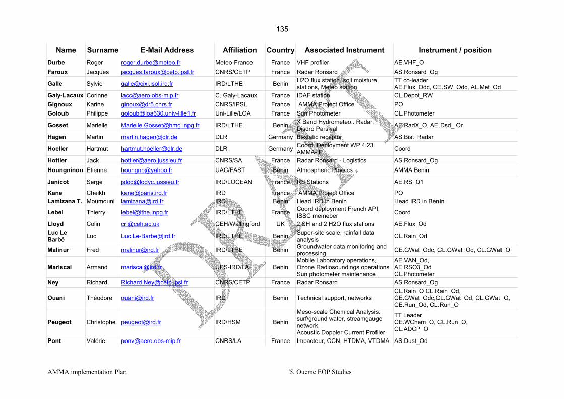
AMMA implementation Plan TT5, Oueme EOP Studies
Name Surname E-Mail Address Affiliation Country Associated Instrument Instrument / position Durbe Roger [email protected] Meteo-France France VHF profiler AE.VHF_O Faroux Jacques [email protected] CNRS/CETP France Radar Ronsard AS.Ronsard_Og
Galle Sylvie [email protected] IRD/LTHE Benin H2O flux station, soil moisture stations, Meteo station
TT co-leader AE.Flux_Odc, CE.SW_Odc, AL.Met_Od
Galy-Lacaux Corinne [email protected] C. Galy-Lacaux France IDAF station CL.Depot_RW Gignoux Karine [email protected] CNRS/IPSL France AMMA Project Office PO Goloub Philippe [email protected] Uni-Lille/LOA France Sun Photometer CL.Photometer
Gosset Marielle [email protected] IRD/LTHE Benin X Band Hydrometeo.. Radar, Disdro Parsival AE.RadX_O, AE.Dsd_ Or
Hagen Martin [email protected] DLR Germany Bi-static receptor AS.Bist_Radar
Hoeller Hartmut [email protected] DLR Germany Coord. Deployment WP 4.23 AMMA-IP Coord
Hottier Jack [email protected] CNRS/SA France Radar Ronsard - Logistics AS.Ronsard_Og Houngninou Etienne [email protected] UAC/FAST Benin Atmospheric Physics AMMA Benin
Janicot Serge [email protected] IRD/LOCEAN France RS Stations AE.RS_Q1
Kane Cheikh [email protected] IRD France AMMA Project Office PO Lamizana T. Moumouni [email protected] IRD Benin Head IRD in Benin Head IRD in Benin
Lebel Thierry [email protected] IRD/LTHE France Coord deployment French API, ISSC memeber Coord
Lloyd Colin [email protected] CEH/Wallingford UK 2 SH and 2 H2O flux stations AE.Flux_Od Luc Le Barbé Luc [email protected] IRD/LTHE Benin Super-site scale, rainfall data
analysis CL.Rain_Od
Malinur Fred [email protected] IRD/LTHE Benin Groundwater data monitoring and processing CE.GWat_Odc, CL.GWat_Od, CL.GWat_O
Mariscal Armand [email protected] UPS-IRD/LA Benin Mobile Laboratory operations, Ozone Radiosoundings operations Sun photometer maintenance
AE.VAN_Od, AE.RSO3_Od CL.Photometer
Ney Richard [email protected] CNRS/CETP France Radar Ronsard AS.Ronsard_Og
Ouani Théodore [email protected] IRD Benin Technical support, networks CL.Rain_O CL.Rain_Od, CE.GWat_Odc,CL.GWat_Od, CL.GWat_O, CE.Run_Od, CL.Run_O
Peugeot Christophe [email protected] IRD/HSM Benin Meso-scale Chemical Analysis: surf/ground water, streamgauge network, Acoustic Doppler Current Profiler
TT Leader CE.WChem_O, CL.Run_O, CL.ADCP_O
Pont Valérie [email protected] CNRS/LA France Impacteur, CCN, HTDMA, VTDMA AS.Dust_Od
135
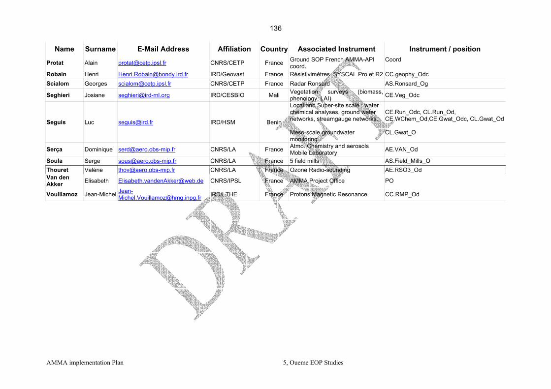
AMMA implementation Plan TT5, Oueme EOP Studies
Name Surname E-Mail Address Affiliation Country Associated Instrument Instrument / position
Protat Alain [email protected] CNRS/CETP France Ground SOP French AMMA-API coord.
Coord
Robain Henri [email protected] IRD/Geovast France Résistivimètres SYSCAL Pro et R2 CC.geophy_Odc Scialom Georges [email protected] CNRS/CETP France Radar Ronsard AS.Ronsard_Og
Seghieri Josiane [email protected] IRD/CESBIO Mali Vegetation surveys (biomass, phenology, LAI) CE.Veg_Odc
Seguis Luc [email protected] IRD/HSM Benin
Local and Super-site scale : water chemical analyses, ground water networks, streamgauge networks, Meso-scale groundwater monitoring
CE.Run_Odc, CL.Run_Od, CE.WChem_Od,CE.Gwat_Odc, CL.Gwat_Od CL.Gwat_O
Serça Dominique [email protected] CNRS/LA France Atmo. Chemistry and aerosols Mobile Laboratory AE.VAN_Od
Soula Serge [email protected] CNRS/LA France 5 field mills AS.Field_Mills_O Thouret Valérie [email protected] CNRS/LA France Ozone Radio-sounding AE.RSO3_Od Van den Akker Elisabeth [email protected] CNRS/IPSL France AMMA Project Office PO
Vouillamoz Jean-Michel [email protected] IRD/LTHE France Protons Magnetic Resonance CC.RMP_Od
136

AMMA implementation Plan TT5, Oueme EOP Studies
Appendix 4
Telecommunication solutions The various technical solutions available in Benin for data transmission from filed sites are listed below, with rough cost estimates. Solution 1: Full internet with satellite connection The configuration encompasses
• A satellite antenna (Geolink provider), located on the X-Port Site in Djougou • A radio link between the Xport site and the RONSARD site in Copargo (20 km N-NE). • A radio link between the XPort site and the mobile laboratory site in Nangatchori (10 km
SE). (See http://www.geolink.com/french/geolinkaccess.htm) Estimated costs: Investment Parabolic antenna, modem, installation and fittings (Geolink) 15 000 € Fire-wall 1 000 € 1. Radio link Copargo-Djougou (mast, antenna, active components, ethernet wiring, grounding)
15 000 €
2. Radio link Nangatchori-Djougou (mast, antenna, active components, ethernet wiring, grounding)
15 000 €
Additional costs (installation, travel fees) 15 000 € Total investment 61 000 € Yearly costs Internet access subscription (512 up/1025 down Kbps), shared band 9 000 € Maintenance geolink antenna (*) 1 300 € Maintenance radio link Copargo (*) 1 600 € Maintenance radio link Nangatchori (*) 1 600 € Total first year Total as from second year
9 000 € 13 500 €
(*) free first year Solution 2 : Full internet with Inmarsat portable modem
The configuration encompasses a portable satellite modem for each site, with direct access to the internet. (See http://www.gme-telecom.com/prod_detail.aspx?Product_ID=225&Nav_ID=213)
Estimated costs are as follows Portable satellite modem (inmarsat) 1 300 € Total investment (1 site) 1 300 € Functionning costs (7 $=~6€/Mo transmitted) Estimate with 8 Go/year :
48 000 €
This solution implies high costs induced for large data amounts.
137

AMMA implementation Plan TT5, Oueme EOP Studies
Solution 3 : GSM modem
The configuration encompasses a portable telephone connected to the instruments. This requires power, a telephone provider (“areeba” is the only one in Djougou), and a computer or an interface to link the instrument and the GSM. A communication protocol has to be established. This solution is suitable for transmission of small data amounts, such as control messages or alarms. It is possible only 15 km around Djougou (range of the GSM relay in Djougou), i.e. Nangatchori, Nalohou, and normally Copargo. This solution has not been tested.
Solution 4: ADSL connection Two providers have recently begun to propose ADSL solutions for internet connections (see e.g. http://www.pharaon-telecom.net/pharaontelecom/). This is a fast-developing technique, and only Cotonou is equipped, and Parakou is planned in some month. Djougou will probably be equipped within half a year. We have yet neither information or experience on success and reliability, nor prices for this solution; however it can become interesting within month. In any case, this requires a classical telephone line on the site where data transmission are planned
138

TT 6. Oceanic campaigns and measurements from open ocean (EOP and SOP)
(Bernard Bourlès, Robert L. Molinari, Peter Brandt)
Reference document (February 2005)
1. Scientific justification and objectives
The oceanographic observations of AMMA will support the land and atmospheric measurements during the three observing periods; Long term Observing Period (LOP), Enhanced Observing Period (EOP), and Special Observing Period (SOP). Detailed scientific rationale for these data is given in both international and national AMMA documents (e.g., French API, EU, US). Specifically, the TT6 aims to provide needed measurements for: 1) the study of processes that determine seasonal to interannual variability of observed sea surface temperature (SST), sea surface salinity (SSS), mixed layer depth and heat content, in the Tropical Atlantic and in the Gulf of Guinea, and their linkage with West African land surface conditions; 2) the study of processes that determine the seasonal evolution of the cold tongue - Inter Tropical Convergence Zone (ITCZ) - West African Monsoon (WAM) system. 3) the study of both ocean and atmosphere boundary layers and air-sea exchanges; 4) the validation of models, satellite data and products.
2. Observing strategy
a. Overall strategy The overall strategy is mainly based on (1) the acquisition of in situ measurements in the eastern
Tropical Atlantic and the Gulf of Guinea (GG) and (2) the integration of these data to characterize the air-land-sea monsoon system during the three observing periods of AMMA (and thereby resolving different timescales ranging from annual to interannual):
For the LOP and EOP observations, the measurements will be principally collected through existing sustained observing networks and acquisition programs (e.g., PIRATA ATLAS buoy network, the Voluntary Observatory Ship (VOS) expendable bathythermograph (XBT) networks, surface drifters of the Global Drifter Program, and the ARGO and CORIOLIS operational programs). LOP/EOP measurements will also be acquired through oceanographic research vessels, coastal stations, tide gauges and the meteorological station at São Tome Island (Eq-6°E). These measurements will be enhanced by additional observations directed at specific monsoon questions. For the SOP WAM process studies, a large number of additional oceanic and meteorological measurements will be collected as presented in details below. The different types of measurements (lagrangian, eurelian, synoptic, surface and subsurface, high frequency acquisition etc…) and the different measured parameters (currents, hydrology and even tracers) should allow obtaining the most complete necessary data sets for the process studies. b. Maps and list of measurements
The oceanic measurements will be described using the framework of the AMMA Observing Periods (i.e., the EOP, LOP and SOP). We first present the oceanographic cruises planned in the framework (or closely linked to) of AMMA in France, US, Germany and Sénégal, before mentioning a few cruises that are of large interest for AMMA and for which collaborations are underway. Then, other international programs or instruments already deployed in the tropical Atlantic are briefly presented.
139

EOP/SOP French cruises:
French EOP and SOP 3 EGEE cruises: French SOP 1 EGEE cruise:
In order to assess interannual and seasonal variability, six EGEE cruises in the Gulf of Guinea are planed in the framework of AMMA-France, with two cruises per year scheduled during the three EOP AMMA years (2005-2007). In order to sample the GG during contrasting climatic situations, the cruises will be carried out in boreal spring-summer (monsoon setting, in phase with the equatorial upwelling onset, i.e. around end of May to July), and boreal fall (late monsoon, end of equatorial upwelling, the ITCZ going back to its southernmost position, i.e. around September-October). The repetition of the cruises during these two opposite seasons during all three years will allow assessment of seasonal and interannual variability. To achieve this objective, the same tracklines will be repeated with particular attention directed at the 10°W meridional section, which has been occupied several times during previous PIRATA and EQUALANT cruises. Presently, the three first EGEE cruises are funded and scheduled. EGEE 1 and EGEE 2 will be carried out with the R/V LE SUROIT in June (June 6 - July 4) and September (September 3 – October 1) 2005 respectively, and the EGEE 3 cruise, during the first phase of the SOP, will be carried out in June (May 25 - July 7) 2006 with the R/V L’ATALANTE. Maintenance (or replacement) of the PIRATA ATLAS moorings located in the Gulf of Guinea (see black dots on the maps above) will also be conducted during these cruises. The section located south of Bénin will complete the SOP terrestrial radio-soundings line planned from Benin and Niger, at 2°50’E. During EGEE 3 (SOP 1 campaign), this section will be occupied in coordination (and simultaneously) with measurements from aircrafts (see also TT8 for more information). This cruise will document the pre-onset and onset of the monsoon offshore, with particular attention directed at surface fluxes, oceanic turbulence and advection of humidity. Atmospheric turbulence measurements will be collected using a turbulent flux measurements system. These atmospheric measurements of radiative and turbulent fluxes will provide observations similar to those obtained with the instrumented mast, positioned in the front of the R/V, during the EQUALANT 1999 cruise. This system will provide oceanic flux measurements for comparison with observations obtained from different methods (i.e., inertio-dissipative, correlation and bulk). Radio-soundings will also be launched from the vessel. In addition to classical current (SADCP and LADCP) and hydrological (T,S,O2) measurements, surface drifters (coll. NOAA/AOML) and ARGO/CORIOLIS profilers will be deployed during each cruise. PIRATA ATLAS buoys will also be maintained during the cruises. Turbulence measurements, by IFM-GEOMAR colleagues and Helium measurements, for upwelling rate estimates by colleagues from the University of Bremen will also taken during some of the cruises.
During the SOP 3 EGEE 4 cruise, occupations of both a Dakar-Cap Vert section and a Guinea Dome cross-section (right) are options. The realization of short cruises from the Senegalese R/V ITAF DEME, if funded, could provide part of needed information needed in this area (see below).
140
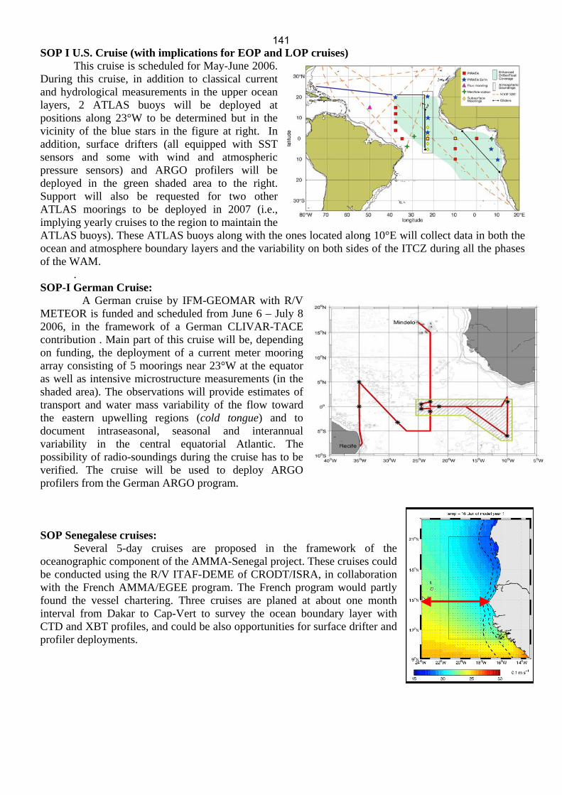
SOP I U.S. Cruise (with implications for EOP and LOP cruises)
This cruise is scheduled for May-June 2006. During this cruise, in addition to classical current and hydrological measurements in the upper ocean layers, 2 ATLAS buoys will be deployed at positions along 23°W to be determined but in the vicinity of the blue stars in the figure at right. In addition, surface drifters (all equipped with SST sensors and some with wind and atmospheric pressure sensors) and ARGO profilers will be deployed in the green shaded area to the right. Support will also be requested for two other ATLAS moorings to be deployed in 2007 (i.e., implying yearly cruises to the region to maintain the ATLAS buoys). These ATLAS buoys along with the ones located along 10°E will collect data in both the ocean and atmosphere boundary layers and the variability on both sides of the ITCZ during all the phases of the WAM.
. SOP-I German Cruise:
A German cruise by IFM-GEOMAR with R/V METEOR is funded and scheduled from June 6 – July 8 2006, in the framework of a German CLIVAR-TACE contribution . Main part of this cruise will be, depending on funding, the deployment of a current meter mooring array consisting of 5 moorings near 23°W at the equator as well as intensive microstructure measurements (in the shaded area). The observations will provide estimates of transport and water mass variability of the flow toward the eastern upwelling regions (cold tongue) and to document intraseasonal, seasonal and interannual variability in the central equatorial Atlantic. The possibility of radio-soundings during the cruise has to be verified. The cruise will be used to deploy ARGO profilers from the German ARGO program. SOP Senegalese cruises: Several 5-day cruises are proposed in the framework of the oceanographic component of the AMMA-Senegal project. These cruises could be conducted using the R/V ITAF-DEME of CRODT/ISRA, in collaboration with the French AMMA/EGEE program. The French program would partly found the vessel chartering. Three cruises are planed at about one month interval from Dakar to Cap-Vert to survey the ocean boundary layer with CTD and XBT profiles, and could be also opportunities for surface drifter and profiler deployments.
141

The list of measurements obtained during the field campaigns is summarized in the following table: Measurements \ cruises EGEE EOP EGEE SOP US SOP German SOP*** Senegalese SOP Hydrology (CTDO2) YES YES YES YES YES* Currents (S-ADCP and/or L-ADCP)
YES YES YES YES NO
Continuous SST and SSS (TSG)
YES YES YES YES NO
Temperature profiles (XBT) YES YES YES YES YES* Salinity profiles (XCTD)
YES YES NO NO NO
Surface drifters deployment (SST)
YES** YES** YES ?? ??
Surface drifters deployment (wind & sea level pressure)
YES** YES** YES ?? ??
ARGO profilers deployment (T&S profiles)
YES YES YES YES YES*
Sea water samples for analysis (S, O2, and nutrients)
YES YES YES YES YES
Ocean microstructures (turbulence)
YES *** YES *** ?? YES NO
Helium (air and ocean) for upwelling rate estimate
YES (partly) **** YES **** NO YES**** NO
Meteorological measurements (classical station -eg BATOS-)
YES YES YES YES YES
Atmospheric microstructures & air sea fluxes (turbulence)
NO YES NO NO NO
Radiosoundings (from vessel) NO YES NO YES NO Sea water samples for analysis (O18, 13C & CO2 parameters)
YES YES NO YES NO
Aerosol (photometer) YES YES NO NO NO Drifting vertical temperature profiles (MARISONDE)
NO YES NO NO NO
*: provided and/or funded by (or in the framework of) AMMA-France (API) **: provided and/or (maybe partly) funded by (or in the framework of) AMMA-US (NOAA) ***: provided and funded in the framework of German CLIVAR-TACE contributions (IFM-GEOMAR) ****: provided and funded in the framework of German SOLAS contribution (University of Bremen) Other LOP/EOP Observations
PIRATA ATLAS buoys:
These 10 buoys obtain oceanic and atmospheric measurements and have been deployed in the tropical Atlantic from 1997 in the framework of the PIRATA program. Their locations are shown in red squares. Four additional buoys will be deployed in 2006 and 2007 by US-NOAA (blue stars) as discussed above. A southeastern extension, endorsed by PIRATA, is also planed with two buoys (blue stars). One of these buoys could also be deployed in 2006 during an EGEE cruise if funded by the regional Benguela Current Large Marine Ecosystem (BCLME) program.
142

PIRATA surface current mooring:
A PIRATA mooring was deployed at 23°W-Equator from December 2001 to December 2002 then from early 2004, close to an ATLAS buoy. The mooring is equipped with an LADCP measuring the current within the upper 100m. In 2004, IFM-GEOMAR added a downward looking ADCP as part of their CLIVAR program. We can thus expect to have a good current survey for the upper 800 m of the water column. Deep current meters and one acoustic source are also installed on this mooring as components of the French “Equatorial Deep Jets” and German CLIVAR-TACE programs, respectively. XBT and TSgraph VOS lines:
VOS provide long time series of subsurface temperature and surface salinity data along regular lines, shown as dashed red lines. These lines have been maintained by NOAA and IRD in the framework of WOCE and CLIVAR. They will continue to be occupied through the EOP and LOP of AMMA. ARGO & CORIOLIS Profilers:
From 2000, the ARGO International project (A global array of profiling floats) and its French component CORIOLIS plan to deploy a network of 3000 autonomous floats that provide temperature and salinity vertical profiles to depths between 1000 m and 2000 m. Each profiler provides data every 10 days and the data are available in real-time through the Global Telecommunications System. The 3000 float array will provide coverage on an average 3° of latitude by 3° of longitude grid. The design life-time of the floats is 4 years. Profilers will be deployed in the tropical Atlantic during AMMA cruises. During the 2005 EGEE cruises, 20 PROVOR (French ARGO profilers) will be launched in the Gulf of Guinea, and at least 10 per year in 2006 and 2007. US and German cruises will also deploy a large number of these profilers in 2006.
Meteorological station:
During October 2003, a meteorological station was installed at São Tomé Island (6°E-0°N) as a component of the French EGEE/AMMA program. This station failed in December 2003 and was repaired in August 2004. The ATLAS suite of atmospheric observations are collected at this station thus extending the PIRATA measurements eastward along the equator. Data are transmitted daily by ARGOS.
In the framework of the Senegalese oceanographic project, if endorsed by Senegal and funded, a meteorological station could be installed at the westernmost point in Dakar (Pointe des Amadies) in 2006.
Tide gauges:
A tide gauge has been maintained by IRD at São Tomé for many years. This tide gauge was positioned by GPS in 2002. Data are transmitted daily by ARGOS, and accessible through internet at the PIRATA web site. Unfortunately, no other gauges are operational along the GG coast. A few tide gauge stations should be installed in Senegal and the GG in 2005 and 2006 in the framework of ODINAFRICA and GOOS Africa projects (personal communication by Angora AMAN, LAPA-Abidjan/RCI). It should be noted that a few older tide gauges maybe available at NOAA that could also be deployed at to be determined locations.
Coastal stations:
A few coastal stations are maintained in some west Africa countries. In the framework of EGEE/AMMA, an evaluation of these stations began and some efforts will be carried out in order to qualify and standardize the SST measurements using “ONSET” temperature sensors. Contacts have already been done in Ivory Coast, Bénin and Togo for these deployments. CRO/ISRA may maintain 7 coastal stations in Sénégal.. Satellite observations:
Remote sensing of SST, sea surface height anomalies, surface wind and ocean color are needed to provide increased spatial and temporal resolution of the eastern tropical Atlantic. Products already exist that combine these data to obtain an integrated look at oceanic surface conditions and these products should be furthered tailored to characterize SOP, LOP and EOP conditions.
143

Current meter mooring array at 23°W-Equator:
Additionally to the PIRATA mooring at 23°W at the equator, IFM-GEOMAR has proposed to install a current meter mooring array in the framework of a German CLIVAR-TACE contribution. In June 2006, IFM-GEOMAR will deploy 5 current meter moorings around this location that consists of ADCPs for the near surface flow, as well as deep current meters and CTD sensors at different depths down to a depth of about 1000m. The mooring array would require cruises for recovery/redeployment that could be used fro repetitions of the 23°W section from Cape Verde to the equator.
Glider:
A Glider section along 23°W from Cape Verde toward the equator is proposed within the German CLIVAR-TACE program. The Glider will measure temperature, salinity and oxygen in the upper 800m of the water column. However the mission depends on availability and technical ability of a Glider-system.
c. Required enhancements to the LOP/EOP network
Surface drifters equipped with thermister chains and meteorological sensors:
The PIRATA array is limited spatially. Satellite tracked surface drifters can be equipped with thermister chains and meteorological sensors (e.g., sea level pressure and wind). The existing 5° by 5° global drifter array and 3° by 3° Argo array in the eastern tropical Atlantic should be enhanced to include these types of drifters. Specific objectives include increased resolution to determine the adequacy of satellite SST observations in this area of atmospheric aerosol occurrences; characterize the temporal development of the monsoon over the eastern tropical Atlantic; determine the oceanic processes that control the evolution of the SST field in the region; and characterize the temporal evolution of the cooling in the equatorial and coastal upwelling regions with respect to the ITCZ and WAM.
Improved meteorological packages on VOS:
The VOS lines described above collect rudimentary meteorological observations. Placing IMET packages on these vessels would greatly improve the quantity and quality of surface meteorological data, which can be used for both weather forecasts and long-term climate studies.
Improved meteorological packages on research vessels:
The vessels that service the Atlantic ATLAS moorings should be equipped with radiosonde systems to obtain characterizations of the atmospheric boundary layer. d. Priorities and potential problems Priorities: Most of the basic networks are funded (e.g., Argo, surface drifters, two ATLAS moorings, VOS XBT lines, etc.) and are of equal importance for the planned process studies, calibration/validation of satellite measurements and numerical model validations. A general priority however is to enhance these networks for improving spatial and temporal resolution of both the atmospheric and oceanic boundary layers. Ensuring the maintenance of the ATLAS buoys (and potential extensions) during all three observing periods specifically for air-sea fluxes studies should also be considered as a priority task. We can also consider that during the SOP 1 French EGGE 3 cruise, ocean and atmosphere boundary layers measurements, turbulence (microstructure) measurements in the upwelling areas and the simultaneous survey from aircraft of the Bénin section are of top priority. Potential problems: - Vessel time:
Several EOP cruises are presently not supported (e.g., EGEE 4, SOP 3 late period during boreal fall 2006 and both EGEE cruises planned in 2007).
144

- Senegal cruises:
The Senegalese (CRODT/ISRA) contribution is also presently not funded.
- ATLAS buoys: ATLAS buoy have failed due to vandalism typically associated with fishing activities in the GG
(e.g., 2004). The PIRATA project will continue through 2006. An evaluation of the utility of the buoys for operational agencies and research studies will be conducted in 2005 to determine the form of the post-2006 array. For instance, the equatorial buoys at 10°W and 0°E could be displaced farther south or in the center of the tropical Atlantic basin to reduce potential vandalism problems.
- Countries clearance:
Cruises trajectories are subject to authorization by countries which control the EEZ in which measurements are planned. Thus, the EGEE cruises track lines may be modified if one of several of the following countries do not provide the requested authorization: Liberia, Ivory Coast, Ghana, Togo, Benin, Equatorial Guinea, Congo, Gabon, São Tomé and Principe, Nigeria, Senegal.
- Observers:
Due to the large number of clearance countries for EGEE cruises and the fact that these countries may impose one (or even two) observers onboard, the number of scientists could be reduced.
e. Link with modeling studies Process studies:
The cruise data will be used for many numerical experiments that will be conducted by the countries involved (e.g., US, France, Germany) as well as other AMMA investigators. Data will be used for model validation (in France: MERCATOR, ROMS), model improvements (e.g. mixing parameters) and/or assimilation schemes validation. Data will also be used for satellite data validation (SST, SLP, sea surface color, SSS) or satellite sensor calibration (SSS). Operational use:
During the EGEE cruises, most of the temperature and salinity profiles (XBT & CDT) will be transmitted in quasi-real time by satellite (ARGOS) to the CORIOLIS Data Center in France for assimilation processes (MERCATOR). All the drifter, Argo and VOS XBT meteorological and oceanic data are transmitted in real-time without cost through the GTS for use by weather and climate forecast centers.
Data synthesis by models:
To obtain a truly four-dimensional view of the oceanic component of the WAM, assimilative models will be used to combine the in situ and remote observations. On weather time-scales, numerical weather prediction models run at operational centers will combine the ocean and land observations to generate weather forecasts. On climate time-scales, operational forecast centers will use the oceanic data to generate SST forecasts that are needed for longer time-scale predictions (e.g., seasonal to interannual).
145

f. Deployment: i) Planning
- during EOP&SOP AMMA cruises : 2005 2006 2007
1 2 3 4 5 6 7 8 9 10 11 12 1 2 3 4 5 6 7 8 9 10 11 12 1 2 3 4 5 6 7 8 9 101 11 2CTD XBT (and a few XCTD) Currents Surface drifters ARGO profilers Sea water samplings Ocean turbulence Air Sea fluxes Radiosoundings Drifting T(z) Helium Tracers analysis
- Additional measurements:
Most of these measurements are obtained thanks to international networks maintained in the framework of CLIVAR, GOOS, etc (eg VOS networks, PIRATA…), and the meteorological station at São Tomé has been installed in October 2003 in the framework of EGEE/AMMA.
2004 2005 2006 2007 1-12 1 2 3 4 5 6 7 8 9 10 11 12 1 2 3 4 5 6 7 8 9 10 11 12 1 2 3 4 5 6 7 8
São Tomé meteorological station XBT VOS network x x x x x x x SSS VOS network x x x x x x x ARGO profilers Only a few x x x x x x São Tomé tide gauge PIRATA ATLAS buoys -> 5 in GG x h o p e f u l l y x h o p e f u l l y h o p e Coastal stations (SST)
x: additional measurements and/or deployments during cruises. ii) Logistical considerations
The cruises and deployment of instruments impose a few constraints that are generally common to every oceanographic cruise and which Task Team members have experience. Most of the problems concern the transportation of equipment to ports used by the research vessels and the need for custom clearances. Efforts to resolve any potential problems should begin now. One constraint for the EGEE cruises will be storing instruments at Cotonou between the two June and September 2005 cruises. This issue can be resolved (for 2005) through communications between TT5 (C.Peugeot/IRD) participants, the Cotonou CRHOB (coll. R.Djiman), and local shipping agents, which have begun. During the SOP 1 EGEE 3 cruise, the communication between the ATALANTE and the aircraft that will simultaneous survey the Bénin section will not be a problem.
Transport of the IFM-GEOMAR microstructure sensor from the METEOR to the French vessel between the German and French cruises is necessary for the SOP cruises.
The logistics for the German glider using in the Gulf of Guinea and along 23°W, as planed in the framework of TACE by IFM-GEOMAR (see below), have to be established in collaboration with French cruises.
146

Partnership
a. Field observations - German (IFM-GEOMAR) biogeochemical program: This cruise is planed in May-June 2006 in the Guinea Dome, on board the R/V METEOR. Some contacts for collaboration are in progress. It would be a potential opportunity for meteorological measurements, ocean microstructure (turbulence) measurements, profiler and surface drifter deployments.
- French PIRATA cruises : These cruises are dedicated to the maintenance of the PIRATA ATLAS buoys network at 23°W-Equator. The four buoys located in the Gulf of Guinea will be maintained during the EGEE cruises from 2005 to 2007. IFM or NOAA could also maintain the 23° W-Eq moorings. These cruises can be opportunities to provide temperature profiles (XBT) and to deploy drifting buoys and ARGO profilers - CLIVAR-Atlantic TACE program: The CLIVAR Atlantic TACE program includes the global observing networks described previously. Other TACE activities represent potential opportunities to deploy additional measurement systems (e.g., gliders along 23°W and in the GG by IFM-GEOMAR. b. Training program
- French PIRATA and EGEE cruises will provide opportunities to embark African students or scientists. For example:
- A student from LPA/UCAD-Dakar (Sénégal) would embark during the next PIRATA cruise in May 2005. He will obtain experience in sea water sampling, CTD acquisition, profiler deployments and XBT launches, that will be necessary during the potential SOP Senegalese ITAF-DEME cruises.
- EGEE/AMMA collaborators of LAPA (Univ./Cocody/RCI) are supposed to contribute to the cruises and to send onboard some students (one per cruise).
- Scientists in Togo and Bénin involved with EGEE/AMMA could also participate on cruises.
- Scientists of the solicited EEZ countries will participate as observers but can also be trained in data acquisition and initial processing.
- ARGO data Center: In the framework of ARGO, two data centers exist: one in US
(NOAA/AOML-Miami) for the South Atlantic (20°N south) and one in France (IFREMER-Brest) for the North Atlantic (20°S north). Training courses will be organized during which African scientists will be trained in oceanographic data treatment. A meeting is planned in Cape Town during May, 2005 to discuss how this activity will operate.
147
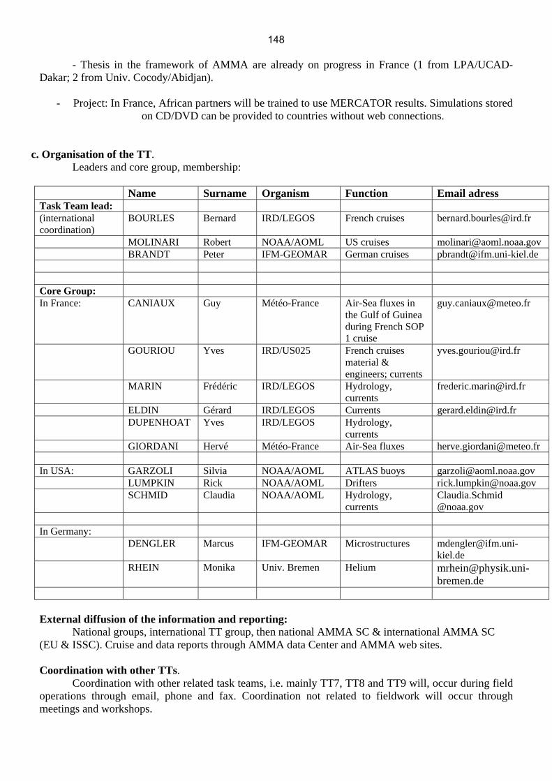
- Thesis in the framework of AMMA are already on progress in France (1 from LPA/UCAD-
Dakar; 2 from Univ. Cocody/Abidjan).
- Project: In France, African partners will be trained to use MERCATOR results. Simulations stored on CD/DVD can be provided to countries without web connections.
c. Organisation of the TT. Leaders and core group, membership:
Name Surname Organism Function Email adress Task Team lead: (international coordination)
BOURLES Bernard IRD/LEGOS French cruises [email protected]
MOLINARI Robert NOAA/AOML US cruises [email protected] BRANDT Peter IFM-GEOMAR German cruises [email protected] Core Group: In France: CANIAUX Guy Météo-France Air-Sea fluxes in
the Gulf of Guinea during French SOP 1 cruise
GOURIOU Yves IRD/US025 French cruises material & engineers; currents
MARIN Frédéric IRD/LEGOS Hydrology, currents
ELDIN Gérard IRD/LEGOS Currents [email protected] DUPENHOAT Yves IRD/LEGOS Hydrology,
currents
GIORDANI Hervé Météo-France Air-Sea fluxes [email protected] In USA: GARZOLI Silvia NOAA/AOML ATLAS buoys [email protected] LUMPKIN Rick NOAA/AOML Drifters [email protected] SCHMID Claudia NOAA/AOML Hydrology,
currents Claudia.Schmid @noaa.gov
In Germany: DENGLER Marcus IFM-GEOMAR Microstructures [email protected]
kiel.de RHEIN Monika Univ. Bremen Helium [email protected]
bremen.de External diffusion of the information and reporting:
National groups, international TT group, then national AMMA SC & international AMMA SC (EU & ISSC). Cruise and data reports through AMMA data Center and AMMA web sites.
Coordination with other TTs. Coordination with other related task teams, i.e. mainly TT7, TT8 and TT9 will, occur during field operations through email, phone and fax. Coordination not related to fieldwork will occur through meetings and workshops.
148

TT7 document 29/07/2005
1
TT7 SOP0 (SOP-A) Implementation Plan (AMMA/DABEX/MAMA)
1. Scientific justification and objectives The African continent is the largest global source of both mineral dust aerosols and biomass burning aerosols. These aerosols are known to significantly affect the solar and terrestrial radiation of the African region thereby modifying the planetary albedo and the outgoing longwave radiation and reducing the radiation flux available to the ocean. In addition to attenuation by scattering, these aerosols absorb a significant proportion of both solar and terrestrial radiation in the atmospheric column and therefore modify the heating rates of the atmosphere. They also significantly influence the surface radiation balance with subsequent effects on the sensible and latent heat fluxes over land surface which may affect the atmospheric dynamics and hydrology of the region. It is to be further added that the aerosol produced during the dry season may play a role in the interannual variability through the modulation of the radiation energy stored in the ocean in the Benin Gulf. On the reverse, rainfall and the development of the vegetation, linked to the penetration of West African Monsoon, indirectly controls dust emission and biomass burning emissions during the dry season.
The importance of the radiative forcing of aerosols, and potential impact on dynamics has been shown at different scales. The lack of inclusion of mineral dust aerosol has recently been highlighted as a major model deficiency in numerical weather prediction models (Haywood et al., 2005). To address this issue, the Met Office Unified model has been developed to include mineral dust generation, transport and deposition in both the global and CAM (crisis area model) versions. On the other hand, aerosols are now included in climate models to predict how they affect long-term climate changes acting directly on radiative budget or indirectly through the modification of cloud life cycle. However interaction processes still need to be better understood and parametrised. Until now, dust and biomass aerosol properties and radiative impact have been characterized in regions where they have been studied independently. Dust uptake from the surface to the atmosphere has extensively been analysed and parametrisations have been developed for modeling (Marticorena and Bergametti, 1995). Source regions for dust and biomass burning particles as well as horizontal transport processes near sources can be identified by radiometry from satellite, but one of the main difficulties remains to precisely identify the vertical extension of the transported particles, which is critical for further dispersion and to the radiative impact due to their significant absorption. Far from the sources, dust or biomass burning aerosols can be frequently observed in elevated layers (Ansmann et al., 2005). Karyampudi et al. (1999) have first used lidar observations from LITE to analyse the dispersion of dust particles over the Atlantic ocean. Combination of in situ, passive and active remote sensing during the SHADE campaign (Tanré et al., 2003) have more recently allowed a better characterization of their radiative impact (Haywood et al., 2003). Biomass burning aerosols have been extensively characterized during the SAFARI campaign (Haywood et al., 2003). Although their radiative forcing is negative over low reflectance surfaces, the observations made during the SAFARI campaign have first evidenced a positive radiative forcing due to elevated biomass particle layers over water clouds (Keil and Haywood, 2003).
Dust and biomass burning aerosol particles have different microphysical and radiative properties (size, shape, absorption) and their mixing is leading to complex modifications. This mixing and further on aging, sedimentation and cloud processing occurring over land and ocean will then result in a variable forcing which needs to be better understood. This is the purpose of the SOPA field experiment.
149

TT7 document 29/07/2005
References Ansmann A., J. Bösenberg, A. Chaikovsky, A. Comeron, S. Eckhardt, R. Eixman, V. Freudenthaler, P. Ginoux, L. Komguem, H. Linné, M.A. Lopez Marquez, V. Matthis, I. Matthis, V. Mitev, D. Müller, S. Music, S. Nickovic, J. Pelon, L. Sauvage, P. Sobolewsky, M. Srivastava and M. Wiegner, 2003 : Long range transport of Saharan dust to northern Europe : The 11-16 October 2001 ourtbreak observed with EARLINET, J. Geophys. Res., 108, D24, 4783, doi:101029/2003JD003757.
Haywood, J.M, Allan, R.P., Culverwell I., Slingo, A., Milton, S., Edwards. J.M., and Clerbaux, N., Can desert dust explain the outgoing longwave radiation anomaly over the Sahara during July 2003? J. Geophys. Res., 110, D05105, doi:10.1029/2004JD005232, 2005. Haywood, J.M., Francis, P., Osborne, S.R., Glew, M., Loeb, N., Highwood, E., Tanré, D., Myhre, G., Formenti, P., and Hirst, E., Radiative properties and direct radiative effect of Saharan dust measured by the C-130 aircraft during SHADE: 1. Solar spectrum, J. Geophys. Res., 108(D18), 8577, doi:10.1029/2002JD002687, 2003. Haywood, J.M., Osborne, S.R. Francis, P.N., Keil, A., Formenti, P., Andreae, M.O., and Kaye, P.H., The mean physical and optical properties of regional haze dominated by biomass burning aerosol measured from the C-130 aircraft during SAFARI 2000, J. Geophys. Res., 108(D13), 8473, doi:10.1029/2002JD002226, 2003.
Karyampudi, V. M., et al., Validation of the Saharan dust plume conceptual model using lidar, Meteosat, and ECMWF data, Bull. Am. Meteorol. Soc., 80, 1045– 1075, 1999.
Keil, A., and Haywood, J.M., Solar radiative forcing by biomass aerosol particles over marine clouds during SAFARI-2000. J. Geophys. Res., 8467, 108(D13), doi:10.1029/2002JD002315, 2003.
Marticorena and Bergametti, 1995, Modelling the atmospheric dust cycle: 1. Design of a soil-derived dust emission scheme: J. Geophys. Res., v. 100, no. D8, p. 16,415-16,430.
Tanré, D., Haywood, J.M., Pelon, J., Léon, J.F., Chatenet, B., Formenti, P., Francis, P., Goloub, P., Highwood, E.J., Myhre, G., Measurement and modeling of the Saharan dust radiative impact: overview of the SaHAran Dust Experiment (SHADE), J. Geophys. Res., 8574, 108(D13), doi:10.1029/2002JD003273, 2003.
1.1 AMMA-EU sub-workpackages with specific interest in this SOP:
WP1.1 WAM and the global climate 1.1.1 Interannual variability and trends of the WAM 1.1.1.a: study of the ocean-atmosphere couplings and their impacts on WAM dynamics 1.1.1.b: analysis of the African ITCZ 1.1.2 WAM impacts on atmospheric composition and global climate (impact of WAM emissions on global oxidant and aerosol budgets, the oxidising capacity and global radiative forcing) WP1.2 Water cycle WP1.3 Land surface-atmosphere feedbacks 1.3.1 Land surface processes and atmospheric forcings 1.3.2 Atmospheric responses to land surface processes 1.3.3 Coupling studies WP1.4 Scale interactions WP2.1 Atmospheric dynamics and convection 2.1.1 Regional to synoptic scale 2.1.2 Synoptic to mesoscale 2.1.3 Mesoscale to cloud scale
150
TT7 document 3 29/07/2005
WP2.4 Aerosols and chemical processes in the atmosphere 2.4.1 Aerosol radiative properties and hygroscopicity 2.4.2 Gas and particle phase chemistry 2.4.3 Surface processes 2.4.4 Effect of convection of chemical and aerosol budgets
1.2 Joint objectives for TT7 The primary objectives of the SOPA are:-
1) To perform high quality in-situ and remote sensing measurements of the optical and physical properties of anthropogenic biomass burning aerosols, mineral dust aerosols, and combinations of the two from sub-Sahelian West Africa.
2) To provide high quality spectral measurements of the solar and terrestrial radiative effects of both biomass burning aerosol and mineral dust aerosol.
3) To determine the consistency between in-situ measurements/satellite and surface based remote sensing methods of the effects on the radiation budget of the Earth of the composite biomass and mineral dust aerosols.
4) To measure and model the effect of the presence of aerosols on the radiation budget at the top of the atmosphere, throughout the atmospheric column, and at the surface of the Earth over land and ocean.
5) To better determine the source regions, source strengths and emission factors of atmospheric aerosols.
6) To contribute to new satellite validation and allow data to be further used in the analysis at the regional and global scale.
7) To improve and validate numerical models (global and regional) to better understand the impact of aerosols on the radiation budget, hence the hydrological cycle and the climate.
The SOP-Dry season objectives are defined by various funded and proposed parts of AMMA. TT7 will organise these objectives into complementary activities, and this is described in subsequent sections of this document. Sections 1.1 – 1.5 list the objectives and subprojects which are concerned with TT7.
2. Overall strategy In order to achieve the scientific objectives listed in section 1, a synergy of observations from ground-based stations, research aircraft, and space-borne instruments will be deployed during SOPA (Figure 9). Two out of three of the aircraft shown in Figure 8 will be operating at the same time; either the BAe146 and the F20 (Plan SOP-A), or the ATR-42 and the F20 (Plan SOP-A’).
151

TT7 document 29/07/2005
Figure 1 : Schematic diagram of the aircraft, ground-based and satellite operations during
SOPA
In the following sections, this document describes the overall strategy of the TT7 group. Namely,
• Optimising the period of investigation
• Optimising the deployment and the flight patterns of the aircraft
• Optimising the instrumentation of the ground-based stations
• Consideration of the satellite capabilities in the region
• Aircraft/satellite/ground based co-ordination via AOC
• Modelling
• Training
• Organisation of TT
• Co-ordination with other TTs
• Ancillary information
• Data processing and distribution
3. Period of investigation The period of investigation has been chosen to maximise the contribution to the
atmospheric aerosol burden from biomass burning and Saharan dust aerosol particles. Figure 2 shows a MODIS image of mineral dust and biomass burning aerosols interacting in January 2005.
152

TT7 document 5 29/07/2005
Figure 2. MODIS image from 5th January 2005 showing the presence of significant mineral
dust and biomass burning aerosol over Nigeria/Benin/Burkina Fassau.
Mineral dust and biomass burning aerosols may be seen as distinct aerosol areas, but their interaction can clearly be identified close to the River Niger in the MODIS image.
Figure 3 shows the aerosol optical depth determined by the MODIS instrument together with the cloud fraction. It can clearly be seen that the cloud fraction is relatively low over the northern regions of the AMMA operating region. Thus conditions of high aerosol optical depth and low cloud amount are prevalent during over the operating region during December – February.
Figure 3 : Average aerosol optical depth for January 2005 as observed with
MODIS/AQUA, and cloud fraction contours (NASA Goddard Earth Science).
153

TT7 document 29/07/2005
Figure 4 shows the annual variability in the number of fires in the region for the year 2000. It can be seen that the greatest number of biomass burning events occur in the sub-Saharan Sahelian region during the December-January-February period, subsequent to which the area of intense biomass burning moves further south reaching its southernmost extent in September.
Figure 4. ATSR satellite retrievals of the number of fires during 2000 as a function of the
month (starting from January top left image).
Further qualitative analysis of the aerosol loading over the operating region may be performed by analysing the aerosol optical depth measurements from the AERONET site at Banizoumbou (13°32N, 2°40E) (Figure 5). Five days of high aerosol load (corresponding to major dust/biomass burning events with optical depth larger than 1) have been observed in 2004 during the January/February operating period shown by the box in Figure 4. Multi-year statistics of the aerosol optical depth at Banizoumbou are presented in Table 1 using threshold AODs of 0.05, 1.0, and 2.0. In general a larger number of dust episodes is seen on statistical basis during the period of February. Over the five year period from 2001-2005, the return period for AODs > 0.5 is 2.5 days, for AODS > 1.0 is 8 days, and for AODS > 2.0 is 26 days. The interannual variability for AODS > 1.0 suggests that return periods of between 4 and 30 days are possible. This analysis suggests that the period of aircraft observations should not to be too short otherwise dust events with AODs > 1 might be missed altogether.
154
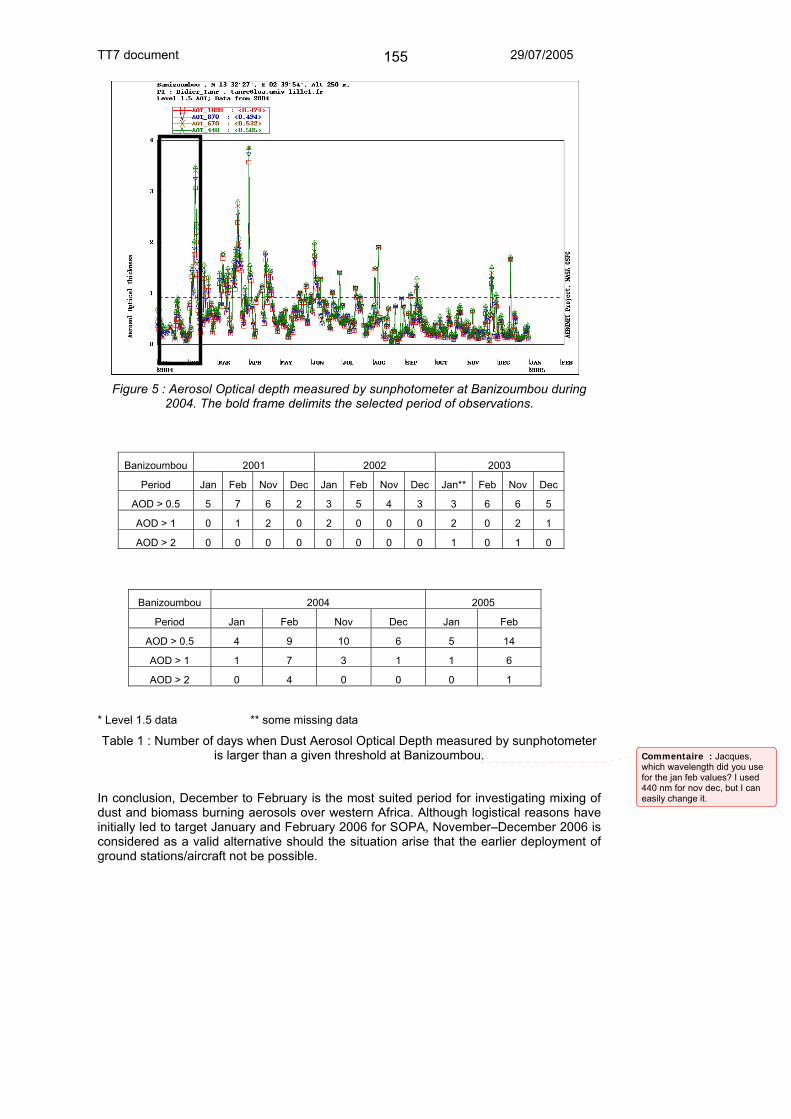
TT7 document 29/07/2005
Figure 5 : Aerosol Optical depth measured by sunphotometer at Banizoumbou during
2004. The bold frame delimits the selected period of observations.
Banizoumbou 2001 2002 2003
Period Jan Feb Nov Dec Jan Feb Nov Dec Jan** Feb Nov Dec
AOD > 0.5 5 7 6 2 3 5 4 3 3 6 6 5
AOD > 1 0 1 2 0 2 0 0 0 2 0 2 1
AOD > 2 0 0 0 0 0 0 0 0 1 0 1 0
Banizoumbou 2004 2005
Period Jan Feb Nov Dec Jan Feb
AOD > 0.5 4 9 10 6 5 14
AOD > 1 1 7 3 1 1 6
AOD > 2 0 4 0 0 0 1
* Level 1.5 data ** some missing data
Table 1 : Number of days when Dust Aerosol Optical Depth measured by sunphotometer is larger than a given threshold at Banizoumbou.
In conclusion, December to February is the most suited period for investigating mixing of dust and biomass burning aerosols over western Africa. Although logistical reasons have initially led to target January and February 2006 for SOPA, November–December 2006 is considered as a valid alternative should the situation arise that the earlier deployment of ground stations/aircraft not be possible.
Commentaire : Jacques, which wavelength did you use for the jan feb values? I used 440 nm for nov dec, but I can easily change it.
155

TT7 document 29/07/2005
4. Aircraft specification, instrumental fits, deployment and flight patterns
4.1. Aircraft specification The main characteristics of the three aircraft are summarised in the Table 2. Note
that the endurance refers to the specific payload carried during the SOPA.
Aircraft F20 ATR-42 BAe146
Operating altitude: 500ft-42,000ft 500ft-25,000ft 50ft-35,000ft
Payload: 1200kg 2500kg 4000kg
Range: 3,200km 3,000km 3,700km
Staffing: 3 crew, 2 scientists 3 crew, 7 scientists 3 crew, 18 scientists
Duration 4.5 hours 3.5 hours 5.5 hours
Table 2. Main characteristics of the three deployed aircraft
4.2. Aircraft Instrumental fits Each of these aircraft will be comprehensively equipped for specific purposes:-
1) F20 aircraft: remote sensing, radiation measurements, in-situ sampling.
2) ATR-42: in-situ measurements of aerosol chemical, physical, and optical properties; radiation measurements to determine the effect of aerosols on atmospheric radiative fluxes.
3) BAe146 aircraft: in-situ measurements of aerosol chemical, physical, and optical properties; radiation measurements to determine the effect of aerosols on atmospheric radiative fluxes and radiances in both the solar and terrestrial regions of the spectrum.
4.2.1. F20 aircraft The F20 will be equipped with a wide range of thermodynamic sensors. In addition, the F20 aircraft will perform remote sensing and radiation measurements:-
• Aerosol profiles (lidar LEANDRE New generation (LNG) operating at 0.35; 0.53 and 1.06 µm).
• Aerosol Optical thickness, Size Distribution (POLDER and MINIMIR+MICROPOL, polarization and directionality of earth reflectances from 440 to 2200 nm)
• Brightness temperatures (CLIMAT Multichannel thermal infrared radiometer)
• Broadband radiometers (visible and IR irradiance, up and down)
• Basic thermodynamics
• Dropsondes
The fit of the aircraft is shown in Figure 6.
156

TT7 document 29/07/2005
Figure 6. The layout of the Falcon 20 aircraft during SOP-A and SOP-A’.
4.2.2. ATR-42 aircraft The ATR42 aircraft will be mostly dedicated to in situ aerosol measurements. The scientific payload will allow measurements of Aerosol equipment
• size distribution (wing-mounted PCASP, FSSP, X-PROBE; GRIMM, DMPS, PCASP)
• aerosol chemistry (filter sampling, impactor sampling)
• aerosol scattering and back-scattering (3 channel TSI nephelometer)
• aerosol absorption (7 channel Magee aethalometer)
• aerosol UV backscattering profile (1 channel lidar)
• aerosol optical depth (PLASMA sun photometer)
• total aerosol number (CNC)
• cloud condensation nuclei counter (CCN)
• cloud absorption (CVI PSAP)
• cloud and interstitial particle size spectra (DMPS CVI; LAS CVI)
Radiation equipment
• solar irradiances (upper and lower Eppley BBRs 0.3-3.0µm).
• UV irradiances (upper and lower Eppley BBRs 0.29–0.3µm).
• terrestrial irradiance (upper and lower pyrgeometers 4.0–45µm).
• j(NO2) fluxes (upper and lower METEO CONSULT)
Other equipment
• Ozone concentrations (UV THERMOELECTRON 49PS)
157

TT7 document 29/07/2005
• CO concentrations (UV THERMOELECTRON 48CS)
The fit of the aircraft is shown in Figure 7.
Figure 7. The layout of the ATR 42 aircraft during SOP-A and SOP-A’.
4.2.3. BAe146 aircraft The BAe146 aircraft will be equipped with in-situ aerosol measurement
instrumentation, and a complementary set of radiation equipment. An example of the aircraft fit used in the Aerosol Direct Radiative Impact Experiment (ADRIEX) is shown in Figure 3. Briefly the following specific equipment directly relevant to the study of aerosols and their direct radiative effects will be carried:- Aerosol equipment:
• size distribution (wing-mounted PCASP, FSSP, SID; CVI PCASP, VACC, PCASP) • aerosol chemistry (Aerodyne mass spectrometer, VACC, filter sampling) • aerosol scattering and back-scattering (3 channel TSI nephelometer) • aerosol absorption (PSAP) • hygroscopic growth (3 channel RH controlled TSI nephelometer) • total aerosol number (CNC) • cloud condensation nuclei counter (CCN) • Aerosol ice nucleation counter (INC)
Radiation equipment: • solar irradiances (upper and lower Eppley BBRs 0.3-0.7�m, 0.3-3.0�m). • terrestrial irradiance (upper and lower pyrgeometers 3.0-30�m). • solar radiances (SWS instrument) • terrestrial radiances (ARIES spectral interferometer) • aerosol lidar (possible)
Other equipment:
158

TT7 document 29/07/2005
• Dropsonde system for measurements of temperature and humidity. • Gaseous measurements of ozone, NOx, CO, CO2. • Whole air sampling for full laboratory analysis.
The fit of the aircraft is shown in Figure 8.
Figure 8. The layout of the BAe146, aircraft during SOP-A.
4.3. Aircraft deployment Three aircraft are involved in the SOPA experiment. These are the French SAFIRE
F20 and ATR-42, and the UK BAe146. The BAe146 has firmly committed to operating from Niamey during January/February 2006. The BAe is a fully certified aircraft with funding from both the Met Office Dust and Biomass burning Experiment (DABEX) and the Dust Outflow and Deposition to Ocean (DODO) project. Significant certification issues surround the deployment of the ATR-42 and the F-20, which means that the ATR-42 will not be certified for operation during January/February 2006, while the status of the F20 will remain unclear until September 2005.
Therefore two provisional plans have been developed:
Plan SOP-A:
159

TT7 document 29/07/2005
• Deployment of BAe146 aircraft in January/February 2006.
• Deployment of the F20 aircraft in January/February 2006.
• ATR-42 not deployed.
Under Plan SOP-A, the BAe146 will concentrate on in-situ measurements, while the F20 will concentrate on remote sensing measurements.
Plan SOP-A’:
• Deployment of BAe146 aircraft in January/February 2006.
• Deployment of the F20 aircraft in December 2006.
• Deployment of ATR-42 aircraft in December 2006.
Under Plan SOP-A’ the BAe146 will operate independently during January/February 2006, and will concentrate on both in situ measurements and remote sensing measurements. During December 2006, the F20 will concentrate on remote sensing measurements, while the ATR-42 will concentrate on in-situ measurements. An intercomparison flight in Europe during November 2006 would also be performed including all three aircraft so that the consistency of the measurements can be assessed.
4.3.1. F20 aircraft The F20 aircraft will be based in Niamey. This aircraft will be mostly flying at high
altitude (around 10 km) between Niamey, M'Bour, Zanderji and Djougou to document the regional coverage of the aerosol distribution and radiative response. Nine scientific flights of approximately 4.5-hour duration are planned (40.5 hours total), Flights will be done in coordination with either the BAE146 or ATR42 for in situ characterization. Plan SOP-A timetable: The dates of the deployment are not been set yet. Depending on certification process, the F20 could be deployed 10 days or more. The field campaign would be held second part of January 2006. A provisional frame is given as 15 January to 30 January. Plan SOP-A’ timetable: The dates of the deployment are not been set yet. Depending on funding the F20 could be deployed either 15 or 23 days. The beginning of the field campaign would be either the last week of November or the first week of December 2006. A provisional frame is given as 27 November to 16 December 2006.
4.3.2 ATR-42 aircraft The ATR-42 aircraft will be based in Niamey. Nine scientific flights of
approximately 3.5-hour duration are planned (31.5 hours total). The aircraft is dedicated to the in situ characterisation of aerosol layers in the troposphere up to approx 5 km. Plan SOP-A timetable: NOT DEPLOYED Plan SOP-A’ timetable: The dates of the deployment are not been set yet. Depending on funding the ATR-42 could be deployed either 15 or 23 days. The beginning of the field campaign would be either the last week of November or the first week of December 2006. A provisional frame is given as 27 November to 16 December 2006. The provisional instrumental fit of the ATR-42 aircraft has been shown in Figure 6.
160

TT7 document 29/07/2005
4.3.3. BAe146 aircraft The UK BAe146 will be first based in Niamey, Niger, and in a second phase in
Dakar, Senegal for operational flying for a period of approximately 2 weeks. The BAe-146 time table is as follows: Plan SOP-A and SOP-A’ timetable: Date (2006) Event 10th January: Cranfield -> Niamey (non-science transit) 11th/12th January: Set-up 13th Jan- 1st Feb (20days): Operational flying (50h=10flights) 2nd February Pack-up 3rd February Niamey -> Dakar (science flight) 4th & 5th Feb: Set-up 6th -15th Feb (10days): Operational flying (30h=6 flights) 16th February: Pack-up 17th February: Dakar -> Cranfield (non-science transit) November 2006 Co-ordinated calibration flight with ATR-42 and F20
Table 3 : BAE 146 Timetable for SOPA and SOPA’
4.4. Aircraft Flight Patterns The three aircraft will perform various independent or co-ordinated flight patterns
as deemed necessary to meet the scientific objectives detailed in section 1. Due to the instrument specifications of the aircraft, each aircraft has specific strengths and weaknesses. The ATR-42 will predominantly concentrate on in-situ sampling, the F20 will predominantly concentrate on remote sensing measurements, and the BAe146 will concentrate on a combination of in-situ and remote sensing measurements. A schematic diagram of the flight plans of the three aircraft is shown in Figure 9.
Figure 9 : schematic diagram of the aircraft operation for plan SOP-A/SOP-A’.
Various types of flight plans have been proposed in accordance to the scientific objectives of the participants:
161

TT7 document 29/07/2005
1. east-to-west flights between Niamey and Dakar, as well from Niamey towards the Bodele depression (one of the largest dust source regions) to document the chemical-physical and optical properties of undisturbed mineral dust and to follow its transport towards the Atlantic
2. north-to-south flights towards the Bay of Benin to document mixing between dust and biomass burning aerosols, and outflow
3. clear-sky ocean flights above the Bay of Benin to allow for satellite validation purposes
4. Biomass burning particle aging analyses. By performing flight legs progressively downwind of local biomass burning sources at different altitude levels, the aging of biomass burning aerosol will be assessed in terms of evolution of the aerosol size distribution, optical properties, hygroscopic nature and mixing with mineral dust.
5. Flight patterns will be defined over ground-based sites in three regions of interest (dust sources, fire regions, and mixed aerosols). Similar measurements may be performed by a stacked profile ascent/descent flying into/down sun by the BAe146. The F20 will simultaneously perform circles at high level with a constant radius will make lidar profiles, flux measurements and monitor the evolution with time.
These flight plans will have to be checked for feasibility with SAFIRE and FAAM. In particular, evaluation of feasibility will be crucial for the ATR-42 which has an expected endurance of 3.5-hours (at the payload carried during SOPA).
The ATR-42 and the F-20 aircraft will be based in Niamey for the majority of the campaign. Operational flights towards the Bay of Benin will be planned in careful consideration of the political situation of the area. Spiral measurements with the ATR embarking PLASMA sun-photometer will allow vertical profiles of extinction.
A typical aerosol-dedicated sortie of the ATR-42 will include vertical profiles to determine the vertical structure, and three-to-four straight level runs of variable horizontal span (duration ≥ 30 min) to allow for in situ sampling (Figure 10).
Figure 10. Proposed flight pattern for in situ aerosol sampling on the ATR42 during SOPA.
162

TT7 document 29/07/2005
Figure 11: Flight pattern for F20 sampling the three aerosol regions
5. Ground-based stations In order to characterize dust, biomass burning and mixed aerosols, the ground-based stations will be used to complete aircraft data by in-situ sampling of aerosol chemical, physical and optical properties. The ground-based stations will provide also with column retrievals of aerosol microphysical and optical properties, with measurements of the aerosol vertical distribution, and with weather measurements for the central operations centre at Niamey airport.
Sal IslandCapo Verde
-22.93°, 16.73°
BanizoumbouNiger
2.66°, 13.54°
Agoufou Mali -1.47°, 15.33°
Illorin Nigeria 4.34°, 8.32°
Dahkla Morroco-15.95°, 23.72°
OuagadougouBukina Faso -1.40°, 12.20°
Cinzana Mali -5.9°, 13.16°
Mbour Senegal-16.95°,14.35°
Lamto Ivory Coast-5.33°, 6.21°
Tamanrasset Algeria 5,51°, 22,78°
Just for AMMA
Djougou Benin1.58°, 9.75°
Zoétélé Cameroon11.88°, 3.25°
Maine Soroa Niger Just for AMMA SOP
Figure 12: AERONET (yellow), IDAF (Blue) and both AERONET/IDAF (green) ground-based stations
163

TT7 document 29/07/2005
There are two characteristic modes of operation for ground-based instruments:
• Continuous monitoring: This mode is typical of instruments belonging to networked stations, i.e. AERONET and IDAF, to local Met Office, to instruments from EOP operations (radiosounding, Sahelian Dust Transect, see TT2b proposal) and the ARM mobile station. The distribution of these sites is shown in Figure 9.
• Intensive monitoring: This mode includes 4 fully equipped ground-based stations (super-sites): Banizoumbou (Niger), Djougou (Benin), M'Bour (Senegal) and Tamanrasset (Algeria). They all coincide with AERONET stations. Instrument are operated only during SOPA. The operation during SOPA' is still at the proposal stage, depending on funding availability. A decision on this should be an outcome of the Leeds meeting. Measurements are a complete set of physico-chemical and optical measurements, including size-segregated sampling for chemical and mineralogical analysis, measurements of number size distributions, spectral scattering and absorption coefficients.
5.1. Continuous monitoring
5.1.1. CIMELS sunphotometers (AERONET) The understanding of the mixing state of aerosols and their radiative properties will
rely on ground-based measurements in the framework of the AERONET network. For the CIMEL sites operational during AMMA experiment (Figure 12), data (level-0) are available at near-real time and they will be used as an element of flight planning.
New retrieval algorithms using measurements of sky radiance have been developed for determining the physical and optical properties of aerosol from sunphotometers (e.g. Dubovik et al, 2000). The consistency of these retrievals will be assessed from aircraft measurements during closure experiments (see section 4.4).
5.1.2. IGAC-DEBITS-Africa (IDAF) IDAF-Africa is part of the global network DEBITS providing chemical
measurements of wet and dry deposition for various African regional ecosystems (http://medias.obs-mip.fr/idaf/program/index.en.php). It provides data on chemical composition of aerosol water-soluble and rainfall and gas concentrations. The IDAF stations are presented in the Figure 9. See the TT2b document for further details.
5.1.3. Mobile ARM site The Atmospheric Radiation Measurement (ARM) mobile site will be situated in
Niamey, and will be operational from October 2005 through Jan 2007. The deployment period encompasses the throughout the SOP-0A and SOP-A’ proposed dates. This site will provide comprehensive high quality surface radiation budget data such as spectrally resolved fluxes, broadband fluxes, sky radiances, micro-pulse lidar observations of aerosol etc. The RADAGAST proposal will ensure that the measurements from GERB and SEVIRI instruments on board the Meteosat-8 platform will be archived during this period enabling a detailed post-campaign analysis of the consistency of radiative transfer models and observations when the detailed measured physical properties of aerosols are excluded and included in radiative transfer calculations. In addition to the standard instrumentation (http://www.arm.gov/sites/amf/instruments.stm) a CIMELS instrument sunphotometer will also be deployed in Niamey. A subset of the ARM instruments will be deployed in Banizoumbou (see list below).
164

TT7 document 29/07/2005
Measurement Manufacturer Instrument Broadband infrared irradiance Eppley Labs PIR Broadband solar irradiance Eppley Labs PSP Multiband global/diffuse solar irradiance Yankee Environmental Systems MFRSR Wind Speed/Wind Direction RM Young 05103-L Barometric pressure Vaissala PTB220 Temperature/Relative humidity Vaissala HMP-45C Rain rate Optical Scientific Instruments ORG-815
Table 4 : Subset of ARM ground-based instruments deployed at Banizoumbou
5.1.4. Sahelian Dust Transect The Sahelian Dust Transect (SDT) has been developed for the EOP in order to
study of role of easterly waves and Mesoscale Convective Systems (MCS) on dust emission, transport and deposition. It includes three fully equipped stations along the E/W transect at 13°N: Banizoumbou (Niger), Cinzana (Mali) and M’bour (Senegal) (Figure 9). At each of these sites, the following parameters will be monitored by the instrument indicated into brackets:
• dust concentration (PM10) at the ground level (TEOM) • total, wet and dry dust deposition (passive and automated collector) • column-integrated aerosol content and properties (PHOTONS/AERONET
photometer) • vertically-resolved aerosol distribution (micro-LIDAR – ISAC-CNR Italy).
Further details are available on the TT2b document.
5.1.5. Lidar systems
From 2005 on, M’Bour will host a Micro Pulsed Lidar (MPL) from the MPL/NASA Network, while Banizoumbou and Djougou will be equipped with non-networked lidar systems from various institutions (University of Munich, ISAC/CNR, LOA/CNRS, SA/CNRS). Acquisition protocols are data treatment are coordinated under WP2.4.1 of AMMA-EU. Further details are given in the TT2b document.
5.1.6. Radiosonde ascents An upgraded radiosounding network is operational during EOP and SOP field
experiments. During the period of intensive observation by the aircraft (12th January – 15th February), radiosonde ascents will be launched twice/day by the radiosonde stations close to and within the operational area of the aircraft (Table 4). This data will augment the aircraft data by providing temperature and humidity measurements above the maximum altitude of the aircraft and ensure that the numerical weather prediction models have data for assimilation purposes.
Country RS Sites lat long
Algeria Tamanrasset 22 48N 05 26E Benin Cotonou 06 21N 02 23E Benin Parakou 09 21N 02 37E Burkina Faso Ouagadougou 12 21N 01 31W Cameroon Douala 04 01N 09 42E Cape Verde Sal 16 44N 22 57W
165

TT7 document 29/07/2005
Chad N'Djamena 12 08N 15 02E Gabon Libreville 00 27N 09 25E Mali Bamako 12 32N 07 57W Mali Tombouctou 16 43N 03 00W Niger Agadez 16 58N 07 59E Niger Niamey (airport) 13 29N 02 10E Senegal Dakar 14 44N 17 30W Senegal Tambacounda 13 46N 13 41W
Table 4: RS station within the operational area of the aircraft
5.1.7. Synoptic visibility measurements Local Met centres will be asked to report local synoptic visibility so that large
biomass burning events and/or mineral dust conditions will be reported to the central operations centre at Niamey airport.
5.2. Super-sites Instrumentation In addition to the ground-based deployment of EOP and network instrumentation,
during SOPA (SOPA’ if applicable), the 4 super-sites will be equipped with instrumentation to characterize the physico-chemical and radiative properties of dust (Banizoumbou, Tamanrasset) and mixed biomass-burning aerosols (Djougou / MBour,).
Details of the deployed instruments and their temporal resolution by site are summarized in Table 5.
In order to insure the comparability of results amongst the different stations, which is delicate particularly for the chemical composition data, an intercomparison of analytical methods used by the implied laboratories for the determination of elemental tracers of mineral dust and elemental/organic carbon will be conducted during autumn 2005 prior to measurements in the field. This is conducted under the supervision of the LISA group. In addition to specific sampling, collection of the PM10 aerosol fraction will be conducted at each site and used as a control parameter.
An intercalibration of radiation instruments should be also performed under the supervision of the LOA group..
5.3. Interactions with others campaigns The SOLAS observational programme Dust Outflow and Deposition in the Ocean
(DODO) will be conducted in collaboration with AMMA (African Monsoon Multidisciplinary Analysis). It will be complemented by dust modelling, laboratory studies and remote sensing products, to produce a quantitative climatology of dust deposition to the Atlantic Ocean, including extensive analysis of iron content. In-situ measurements of aerosol chemical and microphysical properties will be made using the FAAM aircraft and associated instrument suite during dust outflow events. Measurements of the composition of single particles will be made during an intensive 6 weeks experiment at the SOLAS Cape Verde supersite spanning the SOPA (January-February 2006). These measurements will provide data on the dust chemical composition (mixing state of the particles, and the extent to which inorganic salts and organic species are present on the dust surfaces).The sampling procedure and the analysis of aerosols will be in accordance with AMMA practice and hence, the provided physico-chemical data could be used to respond with SOPA objectives.
166
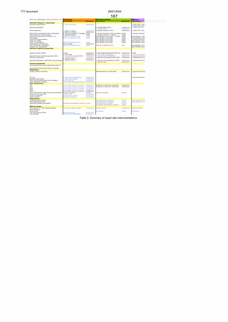
TT7 document 29/07/2005
EOP blue / SOP black / IDAF-AERONET red Djougou Banizoumbou MbourInstruments Sampling Instruments Sampling Instruments
Aerosol Physico- chemistryNumber concentration 1 CPC (0.01-3µm) continuous 1 CPC (0.01-1 µm
1 Laser Part. Cntr Mass concentration 1 TEOM (PM10, PIP) continuous 1 TEOM (PM10)
1 TEOM (PM10) continuousSize distribution 1 optical analyzer continuous 2 optical analyzers (PIP) continuous 1 Laser Part. Cntr
1 SMPS (3-300nm) continuousMass Size concentration and composition 2 cascad impactors (13 stages) 3/day 2 cascad impactors (4 & 13 stages) 2/day 1 cascad impactorSize resolved C concentration 1 cascad impactor 3/day 1 cascad impactor + 1PM10 2/dayChemical composition (minerals + C) PM 2.5/10 filtration lines /week bulk filtration lines (PIP) + 1 PM10 2/day bulk filtration linesMineralogy PM 2.5/10 filtration lines /week bulk filtration lines (PIP) 2/day dry deposition samIndividual characteristics bulk filtration lines (PIP) 2/day 1 cascad impactorFree iron oxides bulk filtration lines (PIP) 2/day bulk filtration linesWSF, Fe speciation PM 2.5/10 filtration lines /week bulk filtration lines (PIP) 2/day bulk filtration linesCCN ability (if foundings) CCN counter continuousWSF Chemical composition PM 2.5/10 filtration lines /week PM 2.5/10 filtration lines /day bulk filtration line (Isotopic iron composition bulk filtration line (Aerosol optical properties
Aerosol column profile 1 lidar continuous 1 lidar (Depolarisation/N2 Raman) continuous 1 lidar1 micro-lidar continuous 1 micro-lidar (day/night) continuous 1 micro-lidar (nigh
Aerosol column optical properties (AOT) 1 sunphotometer AERONET continuous 1 sunphotometer AERONET continuous 1 sunphotometer ADiffusion coefficient 1 nephelometer (1l) continuous 1 spectral (4l) nephelometer (PIP) continuous 1 nephelometer (6
2 nephelometers continuousSpectral Absorption coeff & BC concentrations 1 aethalometer (7l) continuous 1 spectral (7l) aethalometer (PIP) continuous 1 aethalometer (7l
1 aethalometer continuousCloud propertiesCloud emissivity & equivalent black body T°
Horizontal structure and motion of cloudsRadiation: Global, diffuse and direct Shadow-band (7l) radiometer continuous 1 pyranometer (0.3
IR, VIS 4 components radiometer continuous 1 pyranometer (0.7Sensible heat fluxes 1 sonic anemometer continuousPAR: photosynthetically active radiation Licor Quantum continuousNO2 photolysis constant J(NO2) Filter Radiometer Metcon continuousGas Chemistry: O3 active sampler (real time monitoring) continuous Analyzer in real-time monitoring continuousCO active sampler (real time monitoring) continuous Analyzer in real-time monitoring continuousSO2 active sampler (real time monitoring) continuousNOx active sampler (real time monitoring) continuousCOV active sampler (real time monitoring) continuousSO2, HNO3, NH3, NO2, O3 (monthly average) passive samplers /month passive samplers /monthfluxes of CO2 and H2O LICOR 7500 continuousfluxes of isoprene fast isoprene sensor continuousfluxes of NOx dynamic chambers continuousDeposition:Total Deposition fluxes Total deposition samplers /week Total deposition saWet deposition fluxes Wet deposition samplers /event Wet deposition saDissolved rainfall composition Automatic precipitation collector /event Sequential rain sampler /event
Automatic precipitation collector /eventMeteorology: Wind speed, T°, HR, 5-levels profiles lab-made weather station continuous weather mast continuous weather stationWind direction Pluviometry rain gauge /week rain gaugesoil temperature profile lab-made sensor continuoussoil humidity TDR CS 616 CAMPBELL continuous
Table 2: Summary of super-site instrumentations
167

TT7 document 29/07/2005
6. Satellite instruments
MODIS and MISR retrievals of aerosol properties have recently been developed over land surfaces but these retrievals still have a high degree of uncertainty associated with them owing to a reduction in signal-to-noise over bright land surfaces compared to relatively well constrained ocean surfaces. Aircraft flights will be performed in conjunction with the TERRA and AQUA satellites where logistically possible thereby providing suitable data for testing the retrieval algorithms.
In addition to the polar orbiting TERRA and AQUA platforms, the new GERB and SEVIRI sensors mounted on the Meteosat-8 geostationary satellite will be exploited. These sensors provide top of the atmosphere radiances/irradiances at unprecedented temporal resolution.
The CALIPSO satellite is planned to be launched at the end of summer 2005. Validation of its measurements (Lidar, wide field camera and 3 wavelength IR imager) will take place until 2007 ‘level 2 products). As part of the AQUA-Train, its orbit is sun-synchronous with overpasses at 13:30 UTC. The orbits accumulated over 16 days (repeat cycle) are shown in figure 13.
Figure 13 : CALIPSO track over a 16 days period
Aerosol retrievals are currently under development which will allow analysis of the dynamical evolution of dust and biomass burning plumes at a resolution of a few km. These measurements will be validated using aircraft measurements and will in turn allow verification of the transport models.
7. Modelling Various models will be initialised and run for the SOPA period to forecast favourable
event occurrence and to further perform comparisons against in situ, aircraft and satellite measurements allowing assessment of the model performance.
UK Met Office: the Unified model Crisis Area Mesoscale Model (CAMM), has been set up over western Africa. This model is high resolution (TBD km at a latitude of 15oN) and includes dust generation, transport and deposition. In addition, the global NAME chemical
168
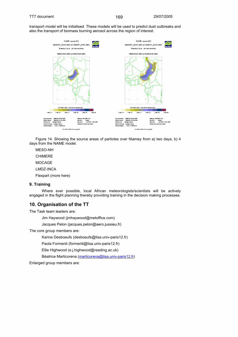
TT7 document 29/07/2005
transport model will be initialised. These models will be used to predict dust outbreaks and also the transport of biomass burning aerosol across the region of interest.
Figure 14. Showing the source areas of particles over Niamey from a) two days, b) 4
days from the NAME model.
MESO-NH
CHIMERE
MOCAGE
LMDZ-INCA
Flexpart (more here)
9. Training Where ever possible, local African meteorologists/scientists will be actively
engaged in the flight planning thereby providing training in the decision making processes.
10. Organisation of the TT The Task team leaders are:
Jim Haywood ([email protected])
Jacques Pelon ([email protected])
The core group members are:
Karine Desboeufs ([email protected])
Paola Formenti ([email protected])
Ellie Highwood ([email protected])
Béatrice Marticorena ([email protected])
Enlarged group members are:
169

TT7 document 29/07/2005
Stéphane Alfaro, Francesco Cairo, Isabelle Chiappello, Hugh Coe, Philippe Goloub, Laurent Gomes, Frederico Fierli, Cyrille Flamant, Pascal Flament, Birgit Heese, Jean-François Léon, Cathy Liousse, Céline Mari, Laurent Menut, Sean Milton, Vincent-Henri Peuch, Veronique Pont, Jean-Louis Rajot, Philippe Ricaud, Tony Slingo, Michael Schulz, Sophie Szopa, Didier Tanré.
10.1 Internal coordination The implementation of the SOP observations will be coordinated within the existing
EU project structure, with separate Aircraft (part of WP4.2.1) and Ground-based (part of WP4.2.2) coordination groups. The leaders of the aircraft group will be Jim Haywood, Ellie Highwood, Jacques Pelon and Paola Formenti; the leader of the ground-based group will be Karine Desboeufs. It will be the work of this TT to ensure that the operations of these groups are complementary.
10.2 Handling of requests for new instruments Requests are discussed by the whole TT7 group and approved by Core Group.
10.3 External diffusion of the information and reporting This TT will consist of members representing all the interest-groups relevant to
SOP-Dry season. This TT will also include representatives of the ICIG, ISSC and CSAM. These individuals will be tasked with reporting information out of the TT.
11. Coordination with other TTs TT1 High frequency radiosondes will be required, perhaps at short notice and in support
of flights.
TT2 Soil moisture and surface flux analyses, from ground sites and remote sensing, may be needed for planning of flights.
TT3 Gourma
TT4 Niamey
TT5 Oueme
Installation of SOP-related ground instrumentation. Overflights and data comparisons. Quick analyses for flight planning.
TT6 Close cooperation regarding flights over the ocean.
TT8 Cooperation in logistical arrangements especially for aircraft.
TT9 Coordinated studies of system lifecycles; trajectories / long-range transport; …
TC1 We can benefit from past (LOP) case-studies in our operational planning, as outlined in the EU project in WP2.1
TC2 This link with the Operational Centres is vital! We need to communicate our requirements in data communication and operational planning.
TC3 Data format; archive resolution; … a major task!
TC4 We need to seek funding for African participation in the operational planning in Niamey.
170
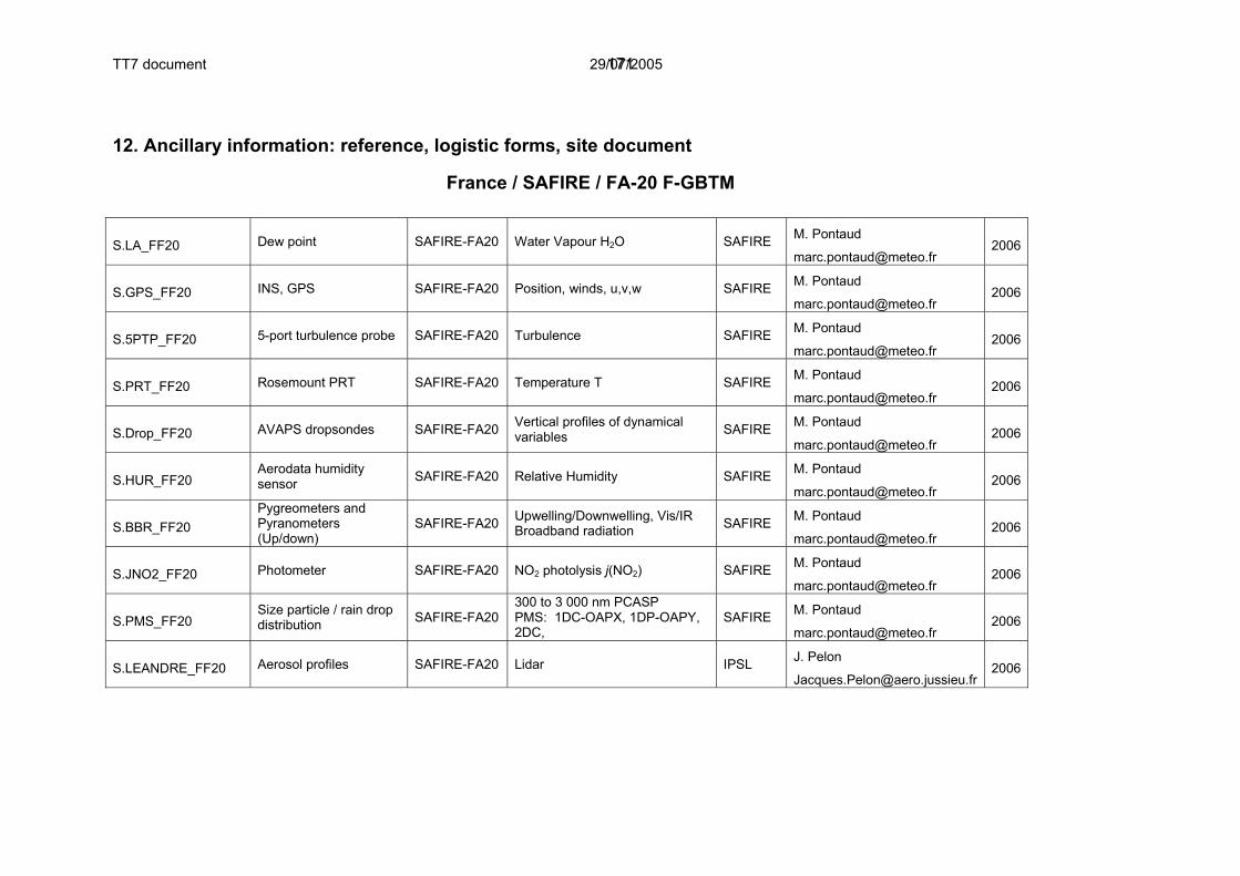
TT7 document 29/07/2005
12. Ancillary information: reference, logistic forms, site document
France / SAFIRE / FA-20 F-GBTM
S.LA_FF20 Dew point SAFIRE-FA20 Water Vapour H2O SAFIRE M. Pontaud
[email protected] 2006
S.GPS_FF20 INS, GPS SAFIRE-FA20 Position, winds, u,v,w SAFIRE M. Pontaud
[email protected] 2006
S.5PTP_FF20 5-port turbulence probe SAFIRE-FA20 Turbulence SAFIRE M. Pontaud
[email protected] 2006
S.PRT_FF20 Rosemount PRT SAFIRE-FA20 Temperature T SAFIRE M. Pontaud
[email protected] 2006
S.Drop_FF20 AVAPS dropsondes SAFIRE-FA20 Vertical profiles of dynamical variables SAFIRE M. Pontaud
[email protected] 2006
S.HUR_FF20 Aerodata humidity sensor SAFIRE-FA20 Relative Humidity SAFIRE M. Pontaud
[email protected] 2006
S.BBR_FF20 Pygreometers and Pyranometers (Up/down)
SAFIRE-FA20 Upwelling/Downwelling, Vis/IR Broadband radiation SAFIRE M. Pontaud
[email protected] 2006
S.JNO2_FF20 Photometer SAFIRE-FA20 NO2 photolysis j(NO2) SAFIRE M. Pontaud
[email protected] 2006
S.PMS_FF20 Size particle / rain drop distribution SAFIRE-FA20
300 to 3 000 nm PCASP PMS: 1DC-OAPX, 1DP-OAPY, 2DC,
SAFIRE M. Pontaud
[email protected] 2006
S.LEANDRE_FF20 Aerosol profiles SAFIRE-FA20 Lidar IPSL J. Pelon
171

TT7 document 29/07/2005
S.Dirac_FF20 Brightness temperatures SAFIRE-FA20 IR radiometer IPSL J. Pelon
OSIRIS_FF20
Polarization and directionnaltiy of earth reflectances from 440 to 2200nm
SAFIRE-FA20 Aerosol Optical thickness, Size Distribution LOA J. F. Léon
[email protected] 2006
MINIMIR+MICROPOL
Polarization and directionnaltiy of earth reflectances from 440 to 2200nm
SAFIRE-FA20 Aerosol Optical thickness, Size Distribution LOA J. F. Léon
[email protected] 2006
CLIMAT Multichannel thermal infrared radiometer. SAFIRE-FA20 Brightness temperatures LOA G. Brogniez
[email protected] 2006
172

TT7 document 29/07/2005
France / SAFIRE / ATR-42 H-MTO
S.SPR_ATR42 Rosemount,Thales Avionic
SAFIRE-ATR42 Static pressure SAFIRE M. Pontaud
[email protected] 2006
S.PRT_ATR42 Rosemount PRT SAFIRE-ATR42 Temperature T SAFIRE M. Pontaud
[email protected] 2006
S.DP_ATR42 Buck Research dew point sensor
SAFIRE-ATR42 Dew point SAFIRE M. Pontaud
[email protected] 2006
S.LA_ATR42 AIR SAFIRE-ATR42 Water Vapour H2O SAFIRE M. Pontaud
[email protected] 2006
S.LWC_ATR42 King Probe, Gerber Probe, JW
SAFIRE-ATR42 Liquid water content SAFIRE M. Pontaud
[email protected] 2006
S.GPS_ATR42 INS, GPS SAFIRE-ATR42 Position, winds, u,v,w SAFIRE M. Pontaud
[email protected] 2006
S.5PTP_ATR42 5-port turbulence nose SAFIRE-ATR42 Turbulence SAFIRE M. Pontaud
[email protected] 2006
S.HEIGHT_ATR42 Thales Avionic radioaltimetre
SAFIRE-ATR42 Height above ground SAFIRE M. Pontaud
[email protected] 2006
S.NOx_ATR42 Chimiluminescence NOx instrument
SAFIRE-ATR42 NO, NO2 in situ SAFIRE M. Pontaud
[email protected] 2006
S.CO_ATR42 IR-CO instrument SAFIRE-ATR42 CO in situ SAFIRE M. Pontaud
[email protected] 2006
S.O3_ATR42 UV-O3 instrument SAFIRE-ATR42 O3 in situ SAFIRE M. Pontaud
[email protected] 2006
S.JNO2_ATR42 Photometer SAFIRE- NO2 photolysis j(NO2) SAFIRE M. Pontaud 2006
173

TT7 document 29/07/2005
ATR42 [email protected]
S.PCASP_ATR42 Externally sampling PCASP
SAFIRE-ATR42 Size distribution (0.2-30 um) SAFIRE M. Pontaud
[email protected] 2006
S.BBR_ATR42 Pygreometers and Pyranometers (Up/down)
SAFIRE-ATR42
Upwelling/Downwelling, Vis/IR Broadband radiation SAFIRE M. Pontaud
[email protected] 2006
S.PMS_ATR42 Size particle / rain drop distribution
SAFIRE-ATR42
PMS: 1DC-OAPX, 1DP-OAPY, 2DC, FSSP SAFIRE M. Pontaud
[email protected] 2006
S.AVIRAD_ATR42 AVIRAD particle inlet SAFIRE-ATR42
Coarse particle inlet (AVIRAD) LISA/LSCE
P. Formenti
2006
S.AVIRAD.GRIMM_ATR42 Optical sizer GRIMM SAFIRE-ATR42 Size distribution (0.3-20 µm) LISA
P. Formenti
2006
S.AVIRAD.AETH_ATR42 7-λ aethalometer SAFIRE-ATR42 Particle soot, black carbon LISA
P. Formenti
2006
S.AVIRAD.NEPH_ATR42 3-λ Nephelometer SAFIRE-ATR42
Spectral Scattering and backscattering coefficients LISA
P. Formenti
2006
S.AVIRAD.Filt_ATR42 filters for individual particle analysis
SAFIRE-ATR42
Particle shape and composition LISA
P. Formenti
2006
S.AVIRAD.DKT_ATR42 4-stage impactors SAFIRE-ATR42
Aerosol composition and mass distribution LISA
P. Formenti
2006
S.VC_ATR42 Particle inlet SAFIRE-ATR42
Aerosol Particle inlet ("Veine communautaire") CNRM L. Gomes
[email protected] 2006
174
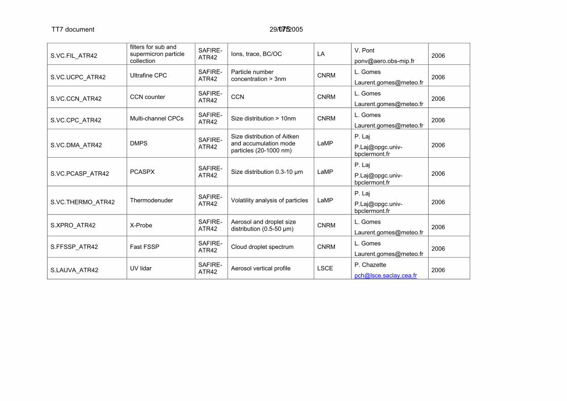
TT7 document 29/07/2005
S.VC.FIL_ATR42 filters for sub and supermicron particle collection
SAFIRE-ATR42 Ions, trace, BC/OC LA V. Pont
[email protected] 2006
S.VC.UCPC_ATR42 Ultrafine CPC SAFIRE-ATR42
Particle number concentration > 3nm CNRM L. Gomes
[email protected] 2006
S.VC.CCN_ATR42 CCN counter SAFIRE-ATR42 CCN CNRM L. Gomes
[email protected] 2006
S.VC.CPC_ATR42 Multi-channel CPCs SAFIRE-ATR42 Size distribution > 10nm CNRM L. Gomes
[email protected] 2006
S.VC.DMA_ATR42 DMPS SAFIRE-ATR42
Size distribution of Aitken and accumulation mode particles (20-1000 nm)
LaMP P. Laj
2006
S.VC.PCASP_ATR42 PCASPX SAFIRE-ATR42 Size distribution 0.3-10 µm LaMP
P. Laj
2006
S.VC.THERMO_ATR42 Thermodenuder SAFIRE-ATR42 Volatility analysis of particles LaMP
P. Laj
2006
S.XPRO_ATR42 X-Probe SAFIRE-ATR42
Aerosol and droplet size distribution (0.5-50 µm) CNRM L. Gomes
[email protected] 2006
S.FFSSP_ATR42 Fast FSSP SAFIRE-ATR42 Cloud droplet spectrum CNRM L. Gomes
[email protected] 2006
S.LAUVA_ATR42 UV lidar SAFIRE-ATR42 Aerosol vertical profile LSCE P. Chazette
[email protected] 2006
175

TT7 document 29/07/2005
13. Data Processing and Availability The aircraft, CIMELS and ARM data will be made freely available to the AMMA
community once the necessary calibration and data processing issues have been completed as stipulated by the AMMA ISSC data protocol.
176

AMMA Task Team 8 – SOP Monsoon: Strategic planning document
Version 1 9 September 2005
Lead authors: TT8 Core Group
177

Providing input to this document:
• Members of TT8 should send comments directly to the TT8 coordinators • Partners in the AMMA-EU consortium should channel their feedback through
workpackage representatives (section 5.1 below) where possible. • Members of other national consortia should provide their feedback through
these groups. • Specific comments on the Aircraft and Ground-based parts of the document
can be sent to Cyrille Flamant and Claire Reeves (Aircraft) or Susanne Crewell (Ground-based).
• If in doubt, general comments on the overall strategy can be sent to Doug Parker in the first instance.
178

1. Scientific justification and objectives Key questions to be addressed by AMMA are listed in the International Science Plan. A number of SOP-Monsoon objectives are also defined by the funded and proposed parts of AMMA. TT8 will organise these objectives into complementary activities, and this is described in subsequent sections of this document. Sections 1.1 – 1.4 list the objectives and subprojects which are concerned with TT8. 1.1 AMMA-EU sub-workpackages with specific interest in this SOP:
WP1.1 WAM and the global climate
1.1.1 Interannual variability and trends of the WAM 1.1.1.a: study of the ocean-atmosphere couplings and their impacts on WAM dynamics 1.1.1.b: analysis of the African ITCZ
1.1.2 WAM impacts on atmospheric composition and global climate (impact of WAM emissions on global oxidant and aerosol budgets, the oxidising capacity and global radiative forcing)
WP1.2 Water cycle WP1.3 Land surface-atmosphere feedbacks
1.3.1 Land surface processes and atmospheric forcings 1.3.2 Atmospheric responses to land surface processes 1.3.3 Coupling studies
WP1.4 Scale interactions
WP2.1 Atmospheric dynamics and convection
2.1.1 Regional to synoptic scale 2.1.2 Synoptic to mesoscale
2.1.3 Mesoscale to cloud scale
WP2.4 Aerosols and chemical processes in the atmosphere 2.4.1 Aerosol radiative properties and hygroscopicity 2.4.2 Gas and particle phase chemistry 2.4.3 Surface processes 2.4.4 Effect of convection of chemical and aerosol budgets
1.2 AMMA-UK Objectives relevant to TT8 / SOP-Monsoon Objectives of relevance to TT8 are: WP1.3 To implement a high resolution land surface-only version of the UM over the tropical North African region, forced by observations, to generate daily analyses of land surface properties and fluxes. The use of MSG data to nudge soil moisture towards observed cloud-screened brightness temperature patterns will produce analyses of greatly improved quality, reducing the sensitivity of the output to poorly observed precipitation data. This technique can be applied where cloud cover permits - from experience at least one in three days in the southern Sahel and more often
179

further north. Coupled with radiation estimates from MSG, this will provide the dominant atmospheric forcing at scales down to 2.5 km. Vegetation and topography data exists at even high resolution, thus permitting the production of high resolution soil moisture and leaf area data. WP1.4 To provide daily surface fields of soil moisture, soil temperature and leaf area for initialisation and validation of Unified Model simulations from micro to synoptic scales, exploring soil-canopy-atmosphere interactions. This work package will also make use of ground data from the CATCH, IMPETUS and other networks provided by the international AMMA consortium, ECMWF atmospheric analyses, rainfall analyses from GPCP, and satellite datasets (MSG and MODIS). WP2.1 To make sub-canopy observations alongside the flux station array, and thereby to quantify the microclimates of the region, in relation to spatial patterns inferred by satellite and aircraft data. WP2.2 To use mesoscale model simulations (on spatial resolutions of 1km or smaller) to attempt to simulate the control of the microclimate by spatial inhomogeneities of surface properties (as provided by WP1). This modelling will be in the form of case studies and idealised simulations. WP3.1 To develop validated model case studies of the diurnal cycle of convection in the continental WAM, and over anomalies of soil moisture. WP3.2 To use case studies to quantify the response of the WAM dynamics to MCSs. WP3.3 To quantify the transport properties of dry and moist convective circulations, on the mesoscale and the continental scale, through model case studies and through use of chemical tracers that act as markers of source regions and of air mass ages. Within this, to model mixing in the monsoon layer and its implication for the monsoon fluxes. WP3.4 To develop synoptic cases studies of AEW structure both north and south of the AEJ, and explore the interaction of these AEWs with soil moisture patterns. WP3.5 To describe the evolution of the SAL on synoptic and diurnal timescales. WP4.1 To make, for the first time, comprehensive observations of the atmospheric composition within the WAM, and thereby to characterise the composition (trace gases and particles) of the different zones within the WAM system. WP4.2 Relate the composition observed in the boundary layer to land surface and vegetation characteristics, as derived from satellite and ground-based observations, and make a first attempt to derive airborne vertical fluxes of biogenic VOCs within the WAM region. WP4.3 Use the improved understanding of the dynamics to evaluate the role of the monsoon circulation in transporting chemical constituents within the WAM region (e.g. boundary layer to mid-troposphere). WP4.4 Use the observational dataset to provide improved constraints on our understanding of how natural emissions (VOC and NOX) impact the chemistry (e.g. O3 and HOX budgets, secondary organic aerosol) of the WAM region, and the production of constituents that may be transported both into the TTL and over regional and continental scales. This objective will relate the chemical control of the particulate material to its ability to act as cloud condensation nuclei and to affect the radiative properties of the particulates. WP5.1 To use observations of the convective outflows in the TTL region to analyse the chemical and dynamical processes occurring in such outflows.
180

1.3 AMMA-France Objectives for TT8 / SOP Monsoon The management structure for AMMA-France is identical to that of the AMMA-EU programme (section 1.1 above). 1.4 SOP-Monsoon-related Objectives from the PIAF The following projects have been proposed as part of the PIAF (African involvement plan – http://www.ird.ne/ammanet/). The full project descriptions can be found by contacting the proposers of each project, or by consulting members of the African coordination committee (CSAM – see http://www.ird.ne/ammanet/). Name Affiliation /
country Research area Project proposal
EL MAJDOUB Ali ACMAD Prévision Numérique Evaluation de l'impact de AMMA sur la PNT, cas du modèle Aladin NORAF
FOAMOUHOUE Kamga
ACMAD Recherches Développement des Applications
Validation des modèles climatiques pour l'exploitation et formation
MUMBA Zilore ACMAD Météorologie Inter-Annual and Intra-seasonal Variability of the West African Monsoon System
B, TRAORE Seydou
AGRHYMET Agrométéorologie, unité Méthodes et applications
Analyse de la variabilité des rendements agricoles en Afrique de l'Ouest en fonction des facteurs climatiques liés à la mousson
ABOU Amani AGRHYMET Hydrologie 1. Evaluation régionale de l'impact du changement climatique sur les ressources en eau en Afrique de l'Ouest; 2. Amélioration de la prévision saisonnière des écoulements en Afrique de l'Ouest
ABOU Amani AGRHYMET Hydrologie Evaluation des techniques de downscaling en Afrique de l'Ouest
ONIBON Hubert Bénin Modélisation stochastique
Analyse des problèmes d'échelles liés à l'étude d'impact de la variabilité climatique sur les ressources en eau
AKPO Aristide Bénin Aérosols, convection, Physique de l'Atmosphère
Impacts des aérosols désertiques sur la Mousson Africaine
DIDE Francis Bénin Météorologie Dynamique de la Mousson - Spécialités de la région du Golfe du Bénin à la Donga
International SOP-Monsoon Implementation, Version 1 D J Parker 6 September 2005
181

YACOUBA Hamma
Burkina Faso Erosion, physique du sol
Impact du changement climatique sur les processus de dégradation de l'environnement au Burkina Faso: Application à l'identification des zones à risque majeur d'érosion et de perte de fertilité dans le bassin supérieur du Nakambé
LENOUO André Cameroun Physique de l'Atmosphère
Impact de la stabilité et de l'humidité sur les Ondes d'Est Africaines
MONKAM David Cameroun Physique de l'atmosphère
Monsoon rainfall behaviour in recent times and impact assessment of El NIÑO and LA NIÑA episodes on local/regional scale in the Northern Africa
CORTE-REAL Joao
Portugal (Cap Vert)
Atmospheric Sciences African Easterly Waves and its interactions with the West African Monsoon System
SILVA Ana Maria Portugal (Cap Vert)
Atmospheric Physics The Health effects of aerosols at Cabo Verde
JEANNE Isabelle CERMES Conception analyses SIG Télédétection Terrain
Méningites et climat. Paludisme et climat : CLIMPAL-Niger
ASSAMOI Paul Côte d'Ivoire Dynamique de l'Atmosphère
Interconnexion des Phénomènes Océaniques et Continentaux dans la Circulation de la Mousson Ouest-Africaine
KOUADIO Georges
Côte d'Ivoire Dynamique de l'Atmosphère,Mesure des flux et paramétrisation
Quantification et modélisation des émissions d'oxydes d'azote par les agrosystèmes fertilisés et impact sur la chimie de l'air en Afrique de l'Ouest
KOUAME Brou Côte d'Ivoire Agriculture Analyses fréquentielles de la pluviométrie : détermination des calendriers culturaux de plantes annuelles
MAHAN N'DJEANGNONMOU Claude
Côte d'Ivoire Océanographie, upwelling Côtier
Upwelling Ivoiro-Ghanéen : fluctuations halieutiques et variabilité climatique
N'GORAN Yao Côte d'Ivoire Rayonnement, Gisement
Etude et exploitation du gisement solaire Ouest Africain à partir de l'imagerie satellitaire(GISOA-SAT)
YAPI Ahoua Côte d'Ivoire Santé, Coordination Impact de la variabilité climatique sur l'étiologie de la maladie asthmatique
YAPI YAPI Grégoire
Côte d'Ivoire Climat, santé Impact de la variabilité climatique sur la transmission du paludisme et des bilharzioses en zone forestière et pré-forestière de Côte d'Ivoire
International SOP-Monsoon Implementation, Version 1 D J Parker 6 September 2005
182

YOBOUE Véronique
Côte d'Ivoire Bilan de l'azote Etude de la pollution atmosphérique dans les capitales africaines en Afrique de l'Ouest et chimie des précipitations en zone de savane humide
ADAMOU Garba EAMAC Dynamique des systèmes
Etude de la dynamique des systèmes convectifs et leurs impacts sur les changements climatiques au Sahel
KONATE Daouda EAMAC Météorologie Etude de l'interconnexion entre l'occurrence et l'intensité des pluies de mousson et les systèmes de temps dans la méditerranée
DIAKITE Cheick Hamala
Mali Géographie 1. Relations entre Méningite et climat pour la mise en place d'un système d'alerte précoce : le cas du Mali. 2. L'eau, Système de prévision de l'inondation du Delta Central du Niger et développement régional
FOFANA Almoustapha
Mali Hydrologie, hydrochimie
Etude hydrologique et hydrochimique des mares du Gourma
MARIKO Adama Mali Hydrologie, Télédétection
Analyse d'impacts et stratégies d'adaptation au changement climatique en zone soudano-sahélienne : cas du Delta intérieur du Niger au Mali
KAMAYE Maâzou Niger Dynamique de l'Atmosphère, Aérosols
Etude statistique de la Variabilité du flux de Mousson et régimes de précipitation en Afrique de l'Ouest
SEYDOU SANDA Ibrah
Niger Aérosols-convection, Variabilité atmosphérique
Aérosols et convection
Zibo Garba Niger Aérosols, Ensablement, Paléoclimatique, SIG Télédétection
Mise en place d'un observatoire "proximal" en bordure du Sahara pour la surveillance et l'analyse des processus éoliens et de leurs impacts (Nguigmi, Mainé-Soroa et Gouré au Niger Oriental, Bassin du Lac Tchad)
Prof OMOTOSO Bayo, OYEBANDE Lekan
Nigeria Meteorology Modelling of mesoscale convective systems over West Africa
CAMARA Moctar Sénégal Physique de l'Atmosphère
Perturbations atmosphériques en Afirque de l'Ouest et activité cyclonique sur l'Atlantique
DIOP Mariane Kane
Sénégal Dynamique des systèmes convectifs
Dynamique des systèmes convectifs de méso-échelle (MCS)
International SOP-Monsoon Implementation, Version 1 D J Parker 6 September 2005
183
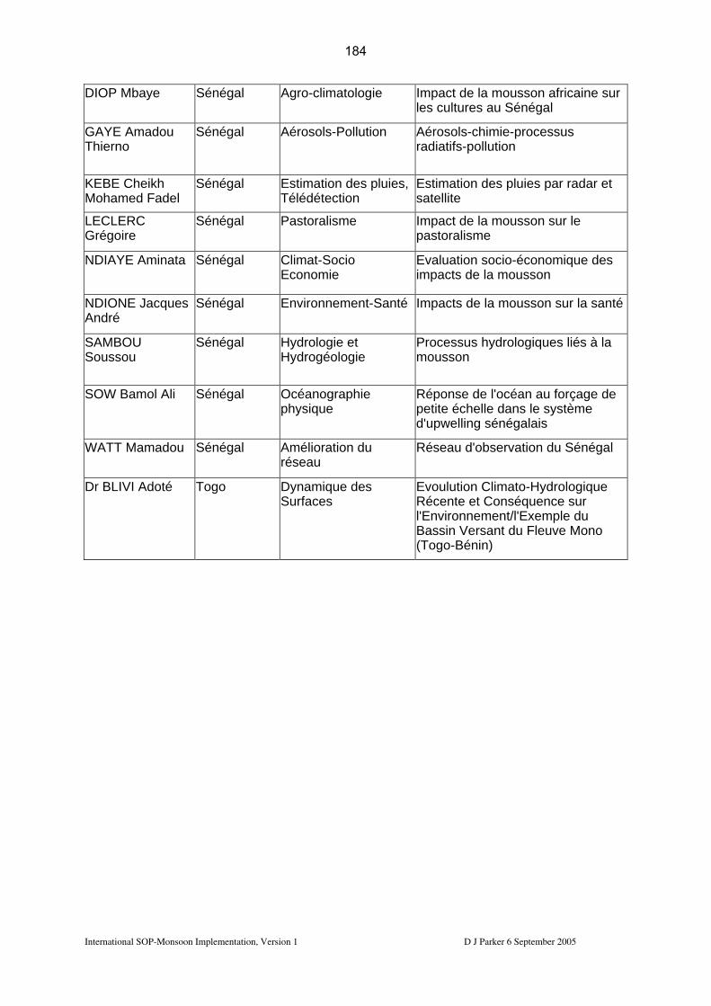
DIOP Mbaye Sénégal Agro-climatologie Impact de la mousson africaine sur les cultures au Sénégal
GAYE Amadou Thierno
Sénégal Aérosols-Pollution Aérosols-chimie-processus radiatifs-pollution
KEBE Cheikh Mohamed Fadel
Sénégal Estimation des pluies, Télédétection
Estimation des pluies par radar et satellite
LECLERC Grégoire
Sénégal Pastoralisme Impact de la mousson sur le pastoralisme
NDIAYE Aminata Sénégal Climat-Socio Economie
Evaluation socio-économique des impacts de la mousson
NDIONE Jacques André
Sénégal Environnement-Santé Impacts de la mousson sur la santé
SAMBOU Soussou
Sénégal Hydrologie et Hydrogéologie
Processus hydrologiques liés à la mousson
SOW Bamol Ali Sénégal Océanographie physique
Réponse de l'océan au forçage de petite échelle dans le système d'upwelling sénégalais
WATT Mamadou Sénégal Amélioration du réseau
Réseau d'observation du Sénégal
Dr BLIVI Adoté Togo Dynamique des Surfaces
Evoulution Climato-Hydrologique Récente et Conséquence sur l'Environnement/l'Exemple du Bassin Versant du Fleuve Mono (Togo-Bénin)
International SOP-Monsoon Implementation, Version 1 D J Parker 6 September 2005
184

2. Observing strategy 2.1 Overall strategy
2.1.1 Aircraft and ground-based measurements A detailed overview of the SOP-Monsoon strategy is included in section 3 of the AMMA International Science Plan (ISP – http://amma.mediasfrance.org/international/documents/index). The overall strategy for the SOP observations is a multidisciplinary, multi-instrument approach. Research aircraft will be used to gain high temporal and spatial resolution measurements while ground-based systems will provide continuity in time. The aircraft will also be used for a ‘Lagrangian’ approach (for instance following weather systems through more than one phase of their evolution), with the ground-based systems giving an Eulerian (fixed location) view. There are two important modes of instrument operation:
1. Intensive observing periods (IOPs) of 1-4 days will be used to focus attention on specific events in the monsoon: notably the effects of convective rainfall events on the various environmental systems. Central to these IOPs will be the deployment of research aircraft. Prescribed IOP patterns are numbered I1, I2, …
2. Intensive monitoring will be conducted throughout the SOP period using ground-based instruments. The activity of some of the EOP monitoring systems (such as the radiosonde network) will be enhanced in this period. This enhancement of monitoring systems will also involve the deployment of SOP ground instrumentation.
Table 2.1 below lists the deployment dates of various instruments. Table 2.1: SOP dates and periods of instrument deployment. Red = Niamey; Blue = Dakar; Yellow = Ouagadougou; Green = Dano; Orange = Djougou; Pink = ‘other’. The SOP-Monsoon periods have been sub-divided into periods of coordinated aircraft deployment labelled SOP1-a, SOP2-a1, SOP2-a2 and SOP2-a3. Details of instruments are contained in later sections of this document.
International SOP-Monsoon Implementation, Version 1 D J Parker 6 September 2005
185
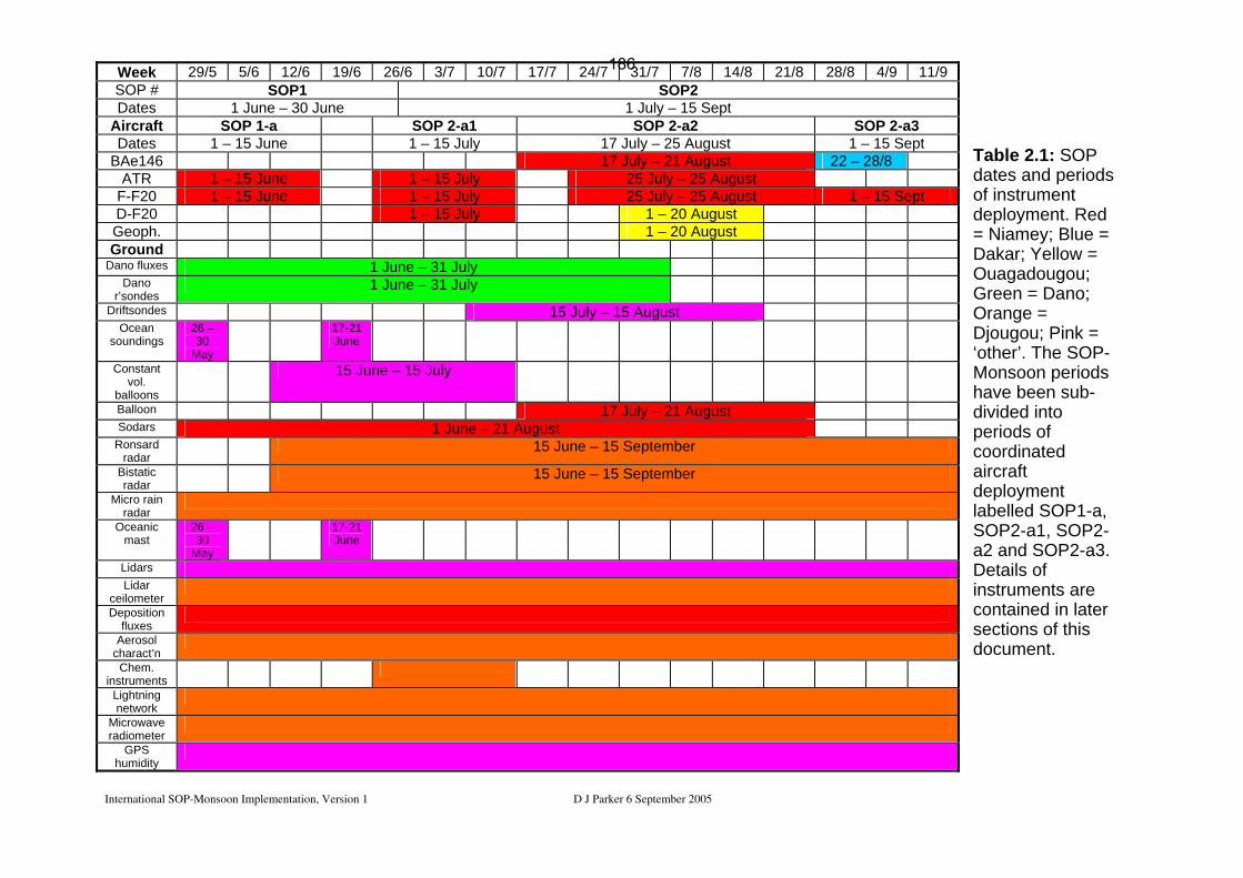
International SOP-Monsoon Implementation, Version 1 D J Parker 6 September 2005
Table 2.1: SOP dates and periods of instrument deployment. Red = Niamey; Blue = Dakar; Yellow = Ouagadougou; Green = Dano; Orange = Djougou; Pink = ‘other’. The SOP-Monsoon periods have been sub-divided into periods of coordinated aircraft deployment labelled SOP1-a, SOP2-a1, SOP2-a2 and SOP2-a3. Details of instruments are contained in later sections of this document.
Week 29/5 5/6 12/6 19/6 26/6 3/7 10/7 17/7 24/7 31/7 7/8 14/8 21/8 28/8 4/9 11/9SOP # SOP1 SOP2 Dates 1 June – 30 June 1 July – 15 Sept
Aircraft SOP 1-a SOP 2-a1 SOP 2-a2 SOP 2-a3 Dates 1 – 15 June 1 – 15 July 17 July – 25 August 1 – 15 Sept
BAe146 17 July – 21 August 22 – 28/8 ATR 1 – 15 June 1 – 15 July 25 July – 25 August
F-F20 1 – 15 June 1 – 15 July 25 July – 25 August 1 – 15 Sept D-F20 1 – 15 July 1 – 20 August Geoph. 1 – 20 August Ground
Dano fluxes 1 June – 31 July Dano
r’sondes 1 June – 31 July
Driftsondes 15 July – 15 August Ocean
soundings 26 –30
May
17-21 June
Constant vol.
balloons
15 June – 15 July
Balloon 17 July – 21 August Sodars 1 June – 21 August
Ronsard radar
15 June – 15 September
Bistatic radar
15 June – 15 September
Micro rain radar
Oceanic mast
26 –30
May
17-21 June
Lidars Lidar
ceilometer
Deposition fluxes
Aerosol charact’n
Chem. instruments
Lightning network
Microwave radiometer
GPS humidity
186

2.1.2 Modelling and satellite observations Model and satellite products will be used for planning of IOPs and aircraft operations (coordinated through the Operations Centre). Need for these products, according to IOP, is detailed in the forecasting requirements for SOPs (Table 3.1 below). It should be noted that a number of products will be required for SOP planning, which are beyond the usual remit of operational weather prediction. Data assimilation with certain datasets from the SOP (radiosondes, dropsondes, driftsondes in particular) is a major priority. Targetted observations using dropsondes, radiosondes and driftsondes could be supported (see I5 plan in section 2.4). Coordination with satellite overpasses needs to be discussed. Representatives of the modelling and satellite communities are members of TT8. 2.2 Ground-based deployment strategy. The list of ground-based instruments proposed for the SOP is included as Appendix GG. There are two characteristic modes of operation for ground-based instruments:
1. Continuous monitoring (M). This mode is typical of instruments measuring vertical profiles or scalar parameters, such as sodars, wind profilers, automatic weather stations, surface energy balance stations. Such stations may need periodic maintenance, in some cases daily. Some of these instruments may be EOP instruments which operate in an enhanced mode during the SOP.
Instrument Code Lead
instit’n PI Location Deployment Mode Radiosoundings Network TT1 EOP-SOP R Ozone soundings AS.RSO3_Od_E LA Thouret Cotonou June-August M X-Band polarised Radar AS_RADX_O IRD Gosset Djougou EOP R
Table 2.2a: EOP ground-based instruments with enhanced operation during SOP.
2. ‘Responsive’ operations (R). In such cases, instrument operation depends critically on the prevailing conditions, and on the particular scientific objectives in question. This mode is characteristic of radar, balloon-borne soundings, and tethered balloon systems. In such cases, the instruments will be linked to the IOP patterns listed in section 2.5 (I1, I2, …). In addition, there may be IOP patterns which involve ground-based instruments alone.
International SOP-Monsoon Implementation, Version 1 D J Parker 6 September 2005
187

Instrument Code Lead instit’n PI Location Deployment Radiosounding Dano AS.Rs_D FZK Kalthoff Dano 1 June - end July
Driftsondes AS.Drift_T1_E CNES/NCAR Drobinski / Parsons N'Djamena 15 Aug.-30 Sep.
Constant volume balloon AS.BVC_T2_E CNES Drobinski Cotonou/Djo? 15 June - 15 July Oceanic soundings OS.RS_SAG_E CNRM Caniaux Atalante/EGGE C-Band Radar Ronsard AS.Ronsard_O_E CNRS Scialom Djougou 15 Jun-15 Sep Tethered balloon U Leeds Parker Niamey 15 July - 21 Aug Table 2.2b: SOP ground-based instruments with a ‘responsive’ mode of operation.
In addition to the instruments listed in Table 2.2b, it is possible that the microlidar to be deployed at Banizoumbou may be operated in special SOP sampling mode – this is currently open to scientific discussion.
2.2.1 Ground-based networks 2.2.1.1 SOP radiosonde network
The RS network is being upgraded and coordinated for the EOP period by TT1. Priorities defined by TT1 are largely for EOP monitoring. For the SOP periods, other priorities for the radiosondes are apparent. Notably, the station at Ouagadougou is a second priority for the EOP but is of higher priority for SOP operations, as part of the 'northern quadrilateral', and is therefore being supported within the AMMA-EU programme. Operation of radiosonde stations:
• The majority of the stations relevant to TT8 are operated by ASECNA, who are a full partner in the AMMA-EU programme, and funded directly through AMMA-EU to deliver the soundings needed.
• Enhanced soundings from the very effective Algerian station at Tamanrasset as also planned.
• The SOP sounding programme will also be enhanced by the provision of soundings by the ARM Mobile Facility (AMF), who will launch 4 soundings per day from Niamey.
• At the Dano site in Burkina Faso, there will be an additional radiosonde station operated by FZK for the SOP.
• There will be ship-launched soundings from the … As for other ground-based instruments, during the SOPs, we focus on 2 modes of operation:
• regular monitoring on a fixed array and • 'responsive' operations, associated with IOPs
International SOP-Monsoon Implementation, Version 1 D J Parker 6 September 2005
188

For the radiosondes, the additional SOP monitoring is defined on the networks provided for the EOP; particularly the 'quadrilaterals' (corresponding to ‘Intensive Flux Arrays’), and the 'monsoon transect'. Notably, while the southern quadrilateral will be supported during the EOP period with 2 soundings per day (TT1), the northern quadrilateral has been a lower priority for the EOP, and will require additional support for the SOPs. The northern quadrilateral is defined in figure 2.1.1.1 as the stations Tombouctou, Agadez, Niamey, Ouagadougou and Parakou. However, due to the orographic influences on the local meteorology of Agadez, there is a strong motivation to replace this station for the SOP by Tahoua (14.9 N, 5.25 E), temporarily making use of the ground-station housed at the EAMAC training school in Niamey. This option is currently being pursued in discussions with ASECNA. A further option for this station might be Kano, in northern Nigeria. Each quadrilateral is defined to contain a radar at the location of the central station. Using the radar and radiosondes, attempts will be made to quantify budgets. The radiosonde quadrilaterals will also therefore be preferred zones for aircraft activities. Currently the radiosonde programme includes provision for 4 soundings per day from the following stations: Southern quadrilateral: Cotonou, Tamale, Parakou, Abuja, Niamey Northern stations and monsoon flux array: Tamanrasset, Agadez
AMMA Priority 1 stations ; ASECNA:AMMA Priority 2 stations ; ASECNA:Temporary stations (planned)Other stations ; ASECNA …………..:GPS stations ; UHF VHF stationsAMMA mesoscales sitesShips
SOP
Djougou
Dakar
SalNouakchott
Conakry
Man
Tambacounda
Nouadhibou
Tindouf
Abidjan
Bamako
Tessalit
Tamanrasset
In Salah
AgadezGaoTombouctou
Niamey KhartoumTahoua
Sarh
N’DjamenaOuagadougou
Ouesso
Bangui
Adis-Abeba
Ngaoundere
Pointe Noire
Libreville
Tamale
Cotonou
AbujaParakou
SOP1&2
SOP3
Figure 2.1.1.1: Radiosonde stations for AMMA, marking the northern, southern and western quadrilaterals. It is planned that the deployment of SOP soundings will be conducted in three modes:
International SOP-Monsoon Implementation, Version 1 D J Parker 6 September 2005
189
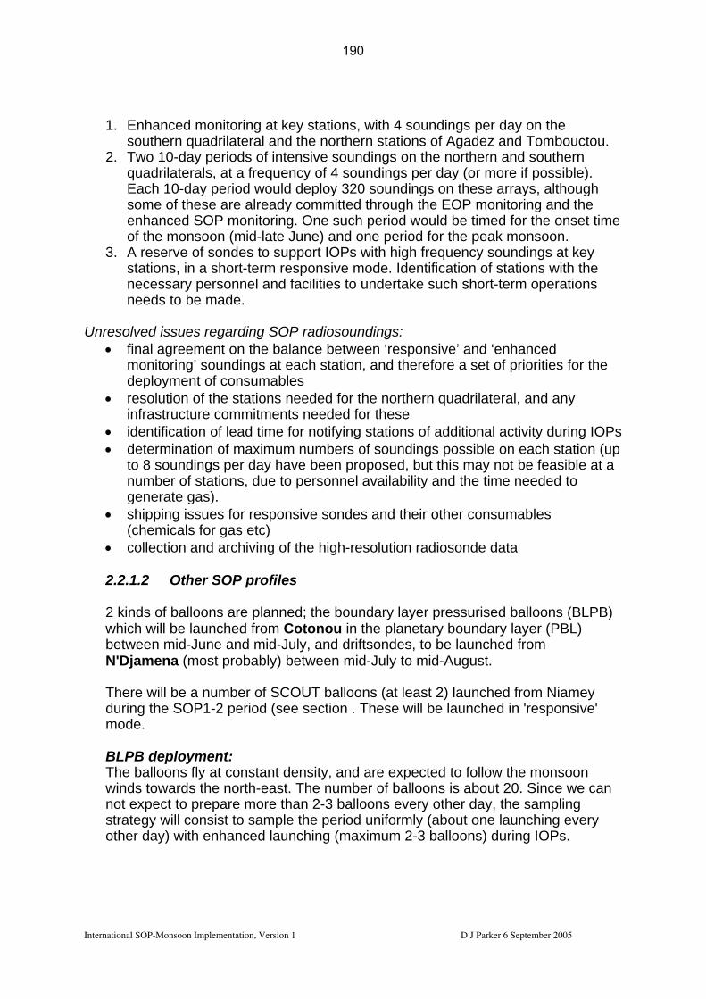
1. Enhanced monitoring at key stations, with 4 soundings per day on the
southern quadrilateral and the northern stations of Agadez and Tombouctou. 2. Two 10-day periods of intensive soundings on the northern and southern
quadrilaterals, at a frequency of 4 soundings per day (or more if possible). Each 10-day period would deploy 320 soundings on these arrays, although some of these are already committed through the EOP monitoring and the enhanced SOP monitoring. One such period would be timed for the onset time of the monsoon (mid-late June) and one period for the peak monsoon.
3. A reserve of sondes to support IOPs with high frequency soundings at key stations, in a short-term responsive mode. Identification of stations with the necessary personnel and facilities to undertake such short-term operations needs to be made.
Unresolved issues regarding SOP radiosoundings:
• final agreement on the balance between ‘responsive’ and ‘enhanced monitoring’ soundings at each station, and therefore a set of priorities for the deployment of consumables
• resolution of the stations needed for the northern quadrilateral, and any infrastructure commitments needed for these
• identification of lead time for notifying stations of additional activity during IOPs • determination of maximum numbers of soundings possible on each station (up
to 8 soundings per day have been proposed, but this may not be feasible at a number of stations, due to personnel availability and the time needed to generate gas).
• shipping issues for responsive sondes and their other consumables (chemicals for gas etc)
• collection and archiving of the high-resolution radiosonde data
2.2.1.2 Other SOP profiles 2 kinds of balloons are planned; the boundary layer pressurised balloons (BLPB) which will be launched from Cotonou in the planetary boundary layer (PBL) between mid-June and mid-July, and driftsondes, to be launched from N'Djamena (most probably) between mid-July to mid-August. There will be a number of SCOUT balloons (at least 2) launched from Niamey during the SOP1-2 period (see section . These will be launched in 'responsive' mode. BLPB deployment: The balloons fly at constant density, and are expected to follow the monsoon winds towards the north-east. The number of balloons is about 20. Since we can not expect to prepare more than 2-3 balloons every other day, the sampling strategy will consist to sample the period uniformly (about one launching every other day) with enhanced launching (maximum 2-3 balloons) during IOPs.
International SOP-Monsoon Implementation, Version 1 D J Parker 6 September 2005
190
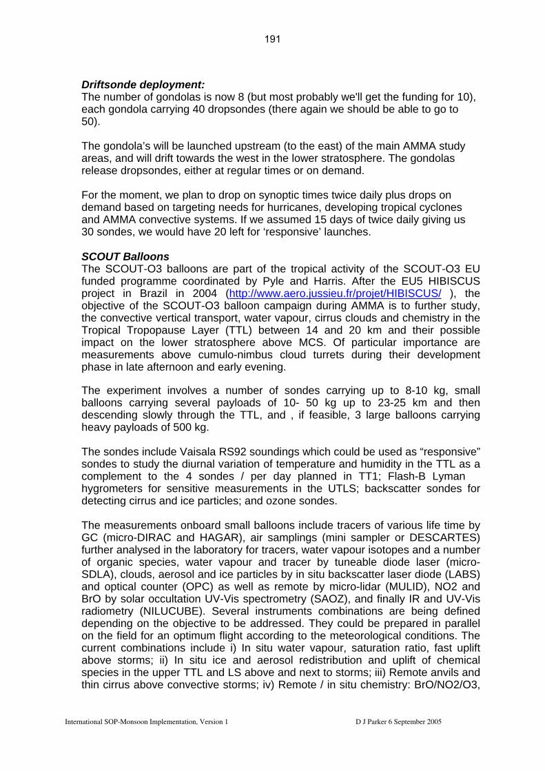
Driftsonde deployment: The number of gondolas is now 8 (but most probably we'll get the funding for 10), each gondola carrying 40 dropsondes (there again we should be able to go to 50). The gondola’s will be launched upstream (to the east) of the main AMMA study areas, and will drift towards the west in the lower stratosphere. The gondolas release dropsondes, either at regular times or on demand. For the moment, we plan to drop on synoptic times twice daily plus drops on demand based on targeting needs for hurricanes, developing tropical cyclones and AMMA convective systems. If we assumed 15 days of twice daily giving us 30 sondes, we would have 20 left for ‘responsive’ launches. SCOUT Balloons The SCOUT-O3 balloons are part of the tropical activity of the SCOUT-O3 EU funded programme coordinated by Pyle and Harris. After the EU5 HIBISCUS project in Brazil in 2004 (http://www.aero.jussieu.fr/projet/HIBISCUS/ ), the objective of the SCOUT-O3 balloon campaign during AMMA is to further study, the convective vertical transport, water vapour, cirrus clouds and chemistry in the Tropical Tropopause Layer (TTL) between 14 and 20 km and their possible impact on the lower stratosphere above MCS. Of particular importance are measurements above cumulo-nimbus cloud turrets during their development phase in late afternoon and early evening. The experiment involves a number of sondes carrying up to 8-10 kg, small balloons carrying several payloads of 10- 50 kg up to 23-25 km and then descending slowly through the TTL, and , if feasible, 3 large balloons carrying heavy payloads of 500 kg. The sondes include Vaisala RS92 soundings which could be used as “responsive” sondes to study the diurnal variation of temperature and humidity in the TTL as a complement to the 4 sondes / per day planned in TT1; Flash-B Lyman � hygrometers for sensitive measurements in the UTLS; backscatter sondes for detecting cirrus and ice particles; and ozone sondes. The measurements onboard small balloons include tracers of various life time by GC (micro-DIRAC and HAGAR), air samplings (mini sampler or DESCARTES) further analysed in the laboratory for tracers, water vapour isotopes and a number of organic species, water vapour and tracer by tuneable diode laser (micro-SDLA), clouds, aerosol and ice particles by in situ backscatter laser diode (LABS) and optical counter (OPC) as well as remote by micro-lidar (MULID), NO2 and BrO by solar occultation UV-Vis spectrometry (SAOZ), and finally IR and UV-Vis radiometry (NILUCUBE). Several instruments combinations are being defined depending on the objective to be addressed. They could be prepared in parallel on the field for an optimum flight according to the meteorological conditions. The current combinations include i) In situ water vapour, saturation ratio, fast uplift above storms; ii) In situ ice and aerosol redistribution and uplift of chemical species in the upper TTL and LS above and next to storms; iii) Remote anvils and thin cirrus above convective storms; iv) Remote / in situ chemistry: BrO/NO2/O3,
International SOP-Monsoon Implementation, Version 1 D J Parker 6 September 2005
191
short lived organic bromine, photolysis rates; v) In situ average transport in convective area. The large balloon payloads include the SPIRALE diode laser for the simultaneous in situ measurement of a large number of species, the MIPAS limb sounding FTIR and a TRIPLE payload made of a cryo-sampler, an H2O isotopes sampler and a hygrometer. According to the wind climatology available in Niamey area where SCOUT-O3 balloon launches are planned in the summer convective period, the balloons will drift westward from Niamey. The maximum measurement range, defined by the telemetry system, is of about 250 km The SCOUT sondes and balloon measurements could contribute significantly to the AMMA objectives, particularly those of the SOP2-a1 and SOP2-a2 aircraft (including M55 Geophysica if confirmed), IOP pattern I4 or of SOP2-a3 (microphysics), IOP pattern 9 and 10, by carrying evening and nighttime observations close and above MCS in the TTL during their maximum phase of development, difficult to perform otherwise. Work is in progress for a precise definition of the flight strategy (e. g. next or far from an MCS for reference, before or after the pass of the MCS, late afternoon or morning, coordination with aircraft) and about the optimum period for the balloon flights. The small balloon campaign is tentatively planned between mid-July and end August 2006. Final decisions will be taken by end October 2005.
Two SCOUT balloon flights have been funded by AMMA-UK, to work with the MCS flights during SOP2-a2. 2.2.1.3 Radars
Radar operations are planned for the central locations of the northern and southern radiosonde quadrilaterals (Niamey and Djougou respectively). However, a suitable radar for Niamey has not yet been committed, and this is a major priority for the AMMA planning in the coming months. At the Djougou site, the Ronsard polarised C-band radar will be deployed during SOP1-2, complemented by the X-port X-band radar which is an EOP facility. Ronsard radar operations: The Ronsard will operate from 15 June to 15 September from Copargo, 20 km north of Djougou, Benin. The Ronsard radar is operating at C-band, Doppler, and has dual polarization capabilities. Scanning speed is 30 seconds per PPI. Its maximum range is either 200 or 100 km, with range gates of 100 or 200 m. The sampling achieved by Ronsard will also be carefully coordinated with that of X-Port in order to access the 3D wind field. The radar will be used to target MCS events, non-organised rainfall (congestus and other types of cumulonimbus) and also has clear-air capabilities.
International SOP-Monsoon Implementation, Version 1 D J Parker 6 September 2005
192

We will have access at the radar site to the MSG images in near real-time. So when an MCS is approaching the radar at 200 km range, a surveillance PPI mode will be activated (3 to 4 successive elevations at relatively low elevation angles from 0.5° to 8°, with the 200 km range). These surveillance PPIs will allow provision of structural information about the approaching convective system (maximum height of leading convective part, convection intensity, horizontal extent, apparent propagation speed). This information will be sent to the AOC and to the pilots of the Falcon 20 in real-time during SOPD to refine the I9 and I10 flight plans (could also help the others ?). When the leading edge of convection arrives at 80-100 km range from the radar, the volumetric scanning mode will be activated, with a 100 km maximum range and the 100 m range gates (best resolution). The volumetric scanning mode details are still under discussion but it should include:
• two interleaved sets of 12 elevations (including a vertical pointing, and the same value of the lowest elevation in the two interleaved sets, for rainfall estimation at sufficient temporal resolution), and
• 2 RHIs (elevation scanning at fixed azimuth) for the microphysical classification of hydrometeors.
The total duration of this would be around 12 minutes (for 3D wind retrieval), with a repetition of the lowest elevation every 6 minutes, which is compatible with the temporal scales required for rainfall estimation, and a new classification of hydrometeors every 6 minutes. This radar sequence will start with the antenna at 0° elevation, then will make the first RHI at a given azimuthal direction. Then the first set of interleaved elevations will be performed, down to the lowest elevation (0.5°, probably). A second RHI will then be performed with an azimuth shifted with respect to the first one in order to describe the variability of the microphysical classification perpendicular to the propagation direction of the MCS. Then the radar sequence will end with the second set of 12 elevations, with a vertical pointing to start and the same lowest elevation as in the first set of interleaved elevations.
Use of the radar data: 1. Rainfall estimation Rainfall estimation is used in soil moisture evaluation and moisture budget computations (supported by fluxes, satellite and radiosonde networks). These issues are simply fundamental to AMMA – related toWG2 (water cycle) and WG4 (land-atmosphere), with important input to WG1 (WAM and climate) and WG5 (impacts).
The rainfall estimated using the radar will be used to refine the spaceborne retrievals of instantaneous rainfall using microwave radiometry over land (there are methods presently developed for this, see WP4.3), and the more statistical rainfall retrievals using geostationary satellites (MSG, see also WP4.3). The radar rainfall data are particularly necessary for the evaluation of scale interactions (EU WP1.4) – matching the cloud-scale rainfall structures with the
International SOP-Monsoon Implementation, Version 1 D J Parker 6 September 2005
193

regional-scale distributions. In the northern Sahel, around and north of Niamey, where vegetation is sparse, the surface state is particularly sensitive to rainfall, so the distributions which are resolved in the rainfall and resulting soil moisture fields impact very strongly on the distributions of surface fluxes on scales from a few km up to the range of the radar. In particular, these scale interactions are critical to: a. local microclimates and social impacts (mosquito environments; agriculture)
(WG5; WP3.x, WP5.x) b. monsoon and cloud dynamics (WG2; WP1.3, WP2.1) c. water cycle (WG2; WP1.2) d. If the radar has dual-polarization capabilities, it can be used in the study of the
interaction between microphysical and dynamical processes (WG2; WP2.1). e. distributions of surface fluxes, and associated model evaluation (WG3; WP2.2,
WP4.1) f. distributions of chemical emissions (WP1.1, WP2.4): in the northern Sahel
where soil emissions are particularly important, patterns of rainfall influence the spatial distributions of chemical and aerosol fluxes from the surface. The radar will be used to analyse these patterns, in association with aircraft missions in the boundary layer.
In terms of the third major goal of AMMA, prediction of the amounts and spatial distributions of rainfall is the primary need of decision-making for West Africa. Radar is an important part of improving our scientific understanding of the rainfall processes. 2. Wind data: for mesoscale analysis of MCS events. These data are important in the understanding of the dynamics of MCSs and their interactions both with the larger-scale monsoon (as in 1(b) above) and the land surface. For instance, from HAPEX-Sahel results it is thought that soil moisture patterns may persist through an intensification of convective cells over patches of wet soil (Taylor and Lebel 1998), and the radar will be used to evaluate the mechanisms of this effect. Analysis of the wind fields in MCS systems will also be needed for the analysis of lightning occurrence, with its consequences for NOx production. 3. Nowcasting of convective storms, for balloon launches and other ground-
based activities; and for coordinated MCS flights in the vicinity of Niamey.
2.2.1.4 GPS network Additional stations are planned for Tombouctou, Ouagadougou and Tamale. These stations will provide an additional north-south transect to the west of the EOP GPS transect. The provision of two north-south arrays for the SOP will reduce the dependence of analyses on the longitude of Niamey, which experience particular climatology due to the upwind topography.
International SOP-Monsoon Implementation, Version 1 D J Parker 6 September 2005
194

GPSGaoGao
DjougouDjougou
NiameyNiamey
CotonouCotonou
BamakoBamako
Ouagadougou
TombouctouTombouctou
TamaleTamale
=IGS
DakarDakar
(Franceville)(Franceville)YamoussoukroYamoussoukro LibrevilleLibreville
=EOP
ConakryConakry Abuja/ Abuja/ MinnaMinna/ / IlorinIlorin
YaoundéYaoundé
AgadezAgadez
ZinderZinder
=SOP
(Sal)(Sal)
DoualaDouala
= other possibilities
TamanrassetTamanrasset
O. Bock & M.N. Bouin AMMA kickoff meeting, Paris, Feb 2005.
Fig. 2.2.1.4: Locations of proposed GPS stations for EOP and SOP.
2.2.1.5 Lidar network The EOP lidar network, which involves an east-west array of stations (coordinated by TT2b) will be enhanced by a north-south transect of stations, with additional lidars located at Tamanrasset (Algeria) and M’bour (Senegal). In addition to these instruments, a lidar ceilometer CT25K will be deployed at Djougou, and a micropulse lidar will be deployed at Niamey by the AMF. 2.2.1.6 Sodar network and tethered balloons
An array of 4 sodar stations is planned for deployment in SOP1 and SOP2. The sodars measure winds continuously up to a level of about 500m, at time resolution of around 10 to 30 minutes and vertical resolution of 10 m or greater (‘Monitoring’ mode). In association with the sodar array, a tethered balloon system (University of Leeds) will be deployed, from which a profile of turbulent fluxes can be made over periods of many hours (in ‘responsive’ mode). It is possible that another tethered balloon system will be deployed in the Gourma region by the CESBIO team (Kergoat). It is planned to deploy the sodars for most of SOP1-2 (1 June – 21 August 2006). The U. Leeds tethered balloon is to be deployed during SOP2-a2 (17 July – 21 August 2006).
International SOP-Monsoon Implementation, Version 1 D J Parker 6 September 2005
195

The combination of these instruments will be used to measure: • local circulations due to surface heterogeneity (vegetation and soil
moisture) • the diurnal cycle of the low level monsoon flow • the vertical structure of the low level monsoon flow • 'sea-breeze'-type flows forced by the land surface • low level wind structure of MCS events at 10-30 minute resolution
The sodars are therefore operated in continuous monitoring mode, and the tethered balloon will be launched as a responsive instrument, in association with IOPs. The deployment of the sodars is planned as a quadrilateral of scale around 100 km, 'tuned' to the typical scales of soil moisture variability resulting from MCS events (see Fig. 2.1.1.6). The U. Leeds tethered balloon will be collocated with one of these sodars.
Typical soil moisture anomaly
4 Sodars
N
100 km
Figure 2.1.1.6a: The proposed arrangement of the sodar network.
The geographical location of the sodar network is planned for the Niamey mesoscale site. Exact locations of the sodars are yet to be established. The balloon will be equipped with a tethersonde and used to measure wind profiles, thermodynamic profiles and turbulent flux profiles. The balloon can in principle be flown to an altitude of 2km; in practice this may be restricted by Air Traffic Control. Deployment will take place in the following modes,
International SOP-Monsoon Implementation, Version 1 D J Parker 6 September 2005
196

1. Land-atmosphere IOPs (I1.1 – I1.7 all possible). The balloon will be deployed on days when the BAe146 or ATR42 are making boundary-layer flights over the mesoscale region in which the balloon is deployed.
2. Nocturnal transition observations. These measurements would be considered on days when no aircraft operations were planned over the balloon region. The balloon will be deployed from 1500 to 1100 (20 hours) to observe the development and erosion of nocturnal circulations. In order for these measurements to be made, good recent estimates of the regional scale (10-100km) soil moisture distributions would need to be available (see I1.4 description).
The system will not be deployed during cumulonimbus events, due to risk of lightning damage 2.2.1.7 Surface flux network Measurements from the EOP surface flux network will be enhanced by an SOP station at Dano (1 June – 31 July), and ship-borne instrumentation for intermittent periods in the SOP. There is strong motivation to attempt to deploy some limited surface flux sensors in the heat low zone, perhaps at the synoptic station at Tessalit (see section 2.6.2 below).
2.2.2 Intensive mesoscale sites 2.2.2.1 Distribution of sites
International SOP-Monsoon Implementation, Version 1 D J Parker 6 September 2005
197
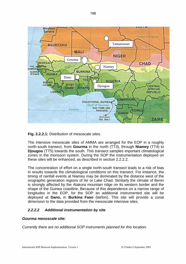
Fig. 2.2.2.1: Distribution of mesoscale sites. The intensive mesosc AMMA rran for t in a rou ly north-south transect, from Gourma in the north (TT3), through Niamey (TT4) to
rds the south. This transect samples important climatological zones in the monsoon system. During the SOP the instrumentation deployed on
ites will be ced, scribed in section 2.2.2.2.
ncentration n nglds ato al c s . Fo stance, the
timing of rainfall events at Niamey may be dominated by the distance west of the ir or Lake Chad. Similarly the climate of Benin
ain ridge on its western border and the
2.2.2.2 Additional instrumentation by site
ourma mesoscale site:
ale sites of are a ged he EOP gh
Tamanrasset
Dano
Gourma
Niamey
Djougou
Djougou (TT5) towa
these s
enhan as de
The co of effort o a si e north-south transect leads to a risk of bias in results towar the clim logic ondition on this transect r in
orographic generation regions of Ais strongly affected by the Atakora mountshape of the Guinea coastline. Because of this dependence on a narrow range of longitudes in the EOP, for the SOP an additional instrumented site will be deployed at Dano, in Burkina Faso (lat/lon). This site will provide a zonal dimension to the data provided from the mesoscale intensive sites.
G Currently there are no additional SOP instruments planned for this location.
International SOP-Monsoon Implementation, Version 1 D J Parker 6 September 2005
198

Niamey mesoscale site:
Instrument Code instit’n PI Deployment Mode Wet and dry deposition fluxes, etc. AS.Dust.ST_flux UP12
Lead
Rajot all SOPs M
UP12 Desboeufs SOP 1-2 M
U Leeds / FZK
Kalthoff / Parker 1 June - 21 Aug M
U Leeds Parker 15 July - 21 Aug R
AR M Jan-Dec 2006 M Djo
2.3 Oceanic measurements
h transects extending this radiosonde
A US c A Germof thisplanneradios
Code Lead instit’n PI Deployment Mode
r AE.PROF_T U Bonn Crewell Jan-Dec 2006 M
15 Jun-15 Sep R istat. Radar (Wind field) AS_BIST.RADAR_O DLR Hagen 15 Jun-15 Sep M
M T_Od UPS Pont SOP2-a1 M
Aerosol characteristion
Sodar network AE.SODAR_
Tethered balloon
M obile facility Slingo
ugou mesoscale site:
Instrument
icrowave RadiometeM
Lidar Ceilometer CT25K AE.CT25K U Bonn Crewell Jan-Dec 2006 M Micro Rain Radar AE_RADK_T U Bonn Crewell Jan-Dez 2006 M C-Band Radar Ronsard AS.Ronsard_O_E CNRS Scialom
B
Lightning detection network DLR Höller SOP1-2 Chemical instrumentation AS.DUS Dano mesoscale site: Instrument Code Lead
instit’n PI Deployment Mode Flux station AS.Flux_D FZK Kalthoff 1 June - end July M Radiosounding Dano AS.Rs_D FZK Kalthoff 1 June - end July R
2.2. The EGEE-3 cruise with the R/V L’Atalante is funded for the period 25 May – 7 July 2006. This cruise will deploy a meteorological instrumented mast and radiosondes, to complement the ‘monsoon transect’ of soundings on land (Cotonou, Parakou, Niamey and ‘Northern stations’). 2 north-soutarray are planned, to the south of Cotonou.
ruise with the R/V Ron Brown is scheduled for the period May-June 2006
an cruise with the R/V Meteor is scheduled for 6 June – 8 July 2006 – much cruise will operate along 23 W although operations along 10 W are also d. The cruise will involve meteorological measurements, including fluxes and oundings.
International SOP-Monsoon Implementation, Version 1 D J Parker 6 September 2005
199

Funding is currently being sought to reactivate the meteorological station at the of São Tomé (6 E, 0 N).
e TT6 document for details.
Aircraft deployment strategy
island See th 2.3
• Based around standard IOP patterns (section 2.5)
. surveys
budget of the thermal low over the Sahara desert is an portant element of the climate of the West African region. Despite its central role,
the very little is known on the dynamics of SHL as well as the diurnal and seasonal evolution of its main characteristics (position, horizontal extent, subsidence aloft, thermodynamic budget, radiative budget, cloud cover) and features (Saharan aerosol layer -SAL, inter-tropical front -ITF). Furthermore, this region is affected by an important horizontal variability of its main characteristics and features at the regional scale. Within AMMA, we propose to characterize the SHL main characteristics (including radiative properties) and features at the daily, seasonal and inter-annual scales. This will be done by two means:
• Carrying coordinated aircraft operations in the IFT region to analyse the dynamical and radiative processes associated with the IFT structure and the Harmattan-Monsoon-African easterly jet (AEJ) interactions during the SOP1-a and SOP2-a1 of AMMA. The role of the surface (soil moisture in particular) will also be investigated. Aircraft measurements will be enhanced by surface measurements made at the Banizoumbou (Niger), Gourma (Mali) and Tamanrasset (Algeria) supersites. Improved knowledge of the above mentioned processes will be obtained by coupling numerical dynamical simulations with airborne and ground-based measurements of atmospheric thermodynamics, surface characteristics and aerosol radiative and optical properties. This strategy is relevant to TT8 and will be described hereafter,
• Characterizing the SAL and IFT structural parameters and radiative properties at the seasonal and interannual time scales in the Sahel and the Sahara using
• Aim to link with ground-based networks • Aim to transmit data to GTS in real time • Aim to use transits for basic science (especially dropsondes, on GTS.)
2.4 IOP strategy The strategy for deployment of responsive instruments in IOPs is based around some standard ‘IOP patterns’ (labelled I1.1 to I5) described in this section. Coordination, funding sources and scientific stakeholders for these IOP patterns are listed in Table 2.4 below. I1 1 Surface-atmosphere-aerosol: Inter-tropical front and heat low(SOP1-a, SOP2-a1 – Flamant) The Saharan heat low (SHL) region is key to understanding the monsoon dynamics nd the thermodynamica
im
International SOP-Monsoon Implementation, Version 1 D J Parker 6 September 2005
200

continuous in situ (e.g. mass concentration, size distribution) and remote sensing (e.g. lidar and sunphotometer derived aerosol optical depth) measurements at the two Sahelian Dust Transect stations of Banizoumbou (Niger) and IER-Cinzana (Mali) as well as in Niamey (Niger) and Tamanrasset (Algeria). This strategy is described in the TT2b implementation plan.
During SOP1-A, the exploration of the inter-tropical front (ITF), which is assumed to be north of Niamey at the time of SOP1-a, will be made using 2 aircraft: the F/ATR in the PBL and the F/F20 flying above the PBL (with the nadir looking LEANDRE 2 lidar) at a level around 500 hPa to enable the documentation of the atmospheric reflectivity and moisture fields in the lower troposphere. The F/F20 will also release dropsondes, as it is highly desirable to document temperature and wind (with a 0.5° or 1° resolution). High horizontal resolution is not necessarily an issue for
for measuring aerosol optical and diative properties in the PBL.
Cowilland
temperature, as opposed to moisture which will be provided by LEANDRE 2. In addition to measuring mean and turbulent variables, the F/ATR will also be equipped with the AVIRAD and HYGRO aerosol packagesra
mbining the in situ aerosol meaurements and laser remote sensing measurements able to retrieve two-dimensional fields of aerosol extin en ction at high horizontal
vertical resolution.
International SOP-Monsoon Implementation, Version 1 D J Parker 6 September 2005
201

Figure I.1-1: proposed aircraft opFT and the SAL during SOP 1-A
erations designed to investigate the structure of the I and SOP 2-A1. Main highlights for the mission are:
1. take off from Niamey and ascend to 6 km msl and 300 m msl for the F/F20 and F/ATR respectively, heading for the Gourma site,
2. exploration of the ITF over the Gourma site. Upon reaching the ITF, the F/F20 will explore the vertical structure of the atmosphere (3 levels) to the south of the position of the ITF at the surface (as forecasted by ACDMAD and determined in the fields from lidar measurements). Two series of vertically stacked flight levels will be performed, separated by at least 50 km. The vertical exploration will last 2h. In the mean time, the F/F20 will describe a square pattern around the position of the IFT at the surface to try to grasp some spatial and/temporal evolution in the coupled monsoon-harmattan-AEJ system,
elling (1h to 2h expected), cend to 6 km msl and 300 m msl for the F/F20 and
UTC to enable a landing in the on the order of 8 or 9 hours,
ded for refuelling in Gao.
s highly desirable to document
SHrefca
3. landing in Gao for refu4. take-off from Gao, as
F/ATR respectively, heading for the north, 5. exploration exploration of the SHL region, heading for Tessalit. Turn around in
Tessalit and fly back towards Gao to sample the atmopsher in the vicinity of the IFT,
6. ferry back to Niamey and landing. All missions are scheduled to start early 0800 or 0900aytime. The overall length of the mission will be d
depending on the time nee During SOP2-a1, the same basic pattern is proposed. D/F20 (equipped with the nadir looking Doppler lidar WIND) flights will be coordinated with the French aircraft flights. The F/F20 will also release dropsondes, as it itemperature (with a 0.5° or 1° resolution) in addition to the remotely sensed wind and water vapour fields. Nevertheless, the D/F20 may not be able to participate to the
L exploration, due to possible overheating problems to be expected during the uelling stop in Gao as the heat might be difficult to withstand for WIND. In this se, the D/F20 will contribute to the IFT exploration and head back to Niamey.
Link with the modelling strategy:
e proposed flight plans will provide three-dimensional (3D) observations of the IFT Th
rements will rom high resolution simulations.
in situ aerosol meaurements and laser remote sensing measurements retrieve two-dimensional (2D) fields of aerosol extinction at high
structure in the region of the Gourma. The thermodynamical structure of the monsoon flow and overlying harmattan will be constructed from dropsonde and lidar
m msl). These measumeasurements in the lower troposhere (below 6 ke compared with the IFT structure obtained fb
Combining theill enable tow
horizontal and vertical resolution to the north and to the south of the IFT. These fields will also be compared with high resolution numerical simulation, to assess the possible impact of saharan aerosol on the IFT structure and propagation. Sensitivity
International SOP-Monsoon Implementation, Version 1 D J Parker 6 September 2005
202

analyses will also be conducted to assess the impact of soil moisture in the region of the IFT. Gr
al soundings to be requested in the northern quadrilateral (Ouagadougou, Tombouctou, Agadez, Niamey
s along the flight pattern in the Gourma site, including
ound-based cooperation:
Coordination with the radiosonding network: addition
Tamanrasset) – at least 4 balloons per day, Coordination with ground sitethe tethered balloon in Hombori, Coordination with the Tamanrasset Supersite, Coordination with the tethered balloon in Niamey.
Forecasting requirements
ud cover: clear-air conditions are needs for optimal use of active and passive ote sensing instruments, S activity: to be avoid during these missions, ition of the IFT: the success of the mission relies strongly on the prediction of position, even though adjustement can be m
Clorem MC PosIFT ade in real time during the opeforc(at t Posmisto eaero Afri itude of the core of the African will be important for pining down the flight levels for the F/F20 and D/F20,
the Gourma region.
rations. It is particularly important that the position of the IFT is accurately asted as optimal conditions seeked for these missions are met when the IFT he surface) is located just north of Gao (Mali), ition of the SHL core: this information is crucial for the SHL survey part of the sion (i.e. after refuelling in Gao) as the aircraft will head directly for that region xperience the strongest gradients in thermodynamical variables and possibly sol properties,
can easterly jet: the position (latitude) and alt
Soil moisture distribution in Satellite data Flights will be planned on the basis of satellite observations of the cloud cover north of Niamey. Satellite observations of the aerosol load and soil moisture to the north of Niamey will also be of great interest for mission planning. Recommendations for enhancement: An airborne soil moisture instrument will enhance significantly the analyses of the land-atmosphere interactions to be achieved in the Gourma region, The exploration of the SHL will be significantly enhanced if the D/F20 was to participate to the coordinated F/20 and F/ATR effort.
1.2: Surface-atmosphere-I aerosol: Squall-line related aerosol emissions
surveys (SOP1-a – Formenti)
International SOP-Monsoon Implementation, Version 1 D J Parker 6 September 2005
203
We propose to quantify the "ne mineral dust emissions in the Sahelian part of north a at various tim les: daily, seasonal and inter-annual. This will be means:
ating the minera budget and properties of dust during squall line s in the Monsoo riod by coupling numerical dynamical simulations
with local measurements of erosion and deposition fluxes, and vertically-
ed hereafter.
issions at the seasonal and interannual time scales in the Sahel using a physical model of dust emission including specific
hoice of observation period
ng SOP 2.
4
t" western Afric e scadone by two
• Estimevent
l t dusn pe
resolved dust concentration, size distribution and mineralogy. Measurements at the ground station of Banizoumbou and onboard aircrafts (F/ATR-42 and F/F-20) will be conducted during the SOP1-a period of AMMA. This strategy is relevant to TT8 and will be describ
• Estimating the mineral dust em
parameterisation for semi-arid areas and continuous measurements of mass concentration, deposition, size distribution and vertical profile at the three Sahelian Dust Transect (SDT) stations of Banizoumbou (Niger), IER-Cinzana (Mali), and M'Bour (Senegal). This strategy is relevant to TT2b and is described in the TT2b implementation plan.
C Observations during SOP1-a are preferred because local dust emissions in the Sahel occur prevalently at the beginning of the monsoon season. Indeed the growing vegetation rapidly inhibits local dust emissions. Moreover, non-precipitating convective systems can occur at the very beginning of the monsoon season. Such non-precipitating squall lines should be the most efficient vector for the injection of locally emitted dust to altitude favourable to long-range transport. The occurrence of precipitation prevents the type of operations to be conducted duri Based on the surface observations of the occurrence of squall lines conducted by Rajot (2001) at Banizoumbou between 1995 and 1998 (May through July), the observation period can be further narrowed down. Indeed, the most favourable period for such a study is June (see table below), when a squall line event can be expected every 2 to 4 days. Period Occurrence of squall line events Mean Min Max 01–15 May 1 0 2 16–31 May 3 1 4 01–15 June 4.25 2 7 16–30 June 5.5 5 7 01–15 July 3.75 2 5 15–31 July 2.5 1 Finally, logistical constraints of aircraft availability within AMMA led to target the period 1–15 June (SOP1-a) as the dedicated airborne observation period of I1.2. Ground-based measurements will continue until 15 July, thus encompassing the entire SOP1-a – SOP2-a1 field phases.
International SOP-Monsoon Implementation, Version 1 D J Parker 6 September 2005
204
Description of observational strategy The I1.2 type missions are designed to estimate, at the relevant time-scale, the quantity of dust mobilized as well as deposited by the squall lines, in order to determine the net quantity of dust that remains in the atmosphere after the passage of a squall line and therefore that can be long-range transported. Simultaneously, the physico-chemical and optical properties of the emitted dust across its size spectrum should be determined so to able to estimate its impact on the solar and terrestrial radiation. To do so, we propose an experimental approach based on measurements of
ust mineralogical composition and mass distribution by filter/impactor sampling; (5) dust number distribution for particles between 0.3 and 20 µm optical diameter by optical counting; (6) spectral scattering and absorption coefficients by nephelometer and aethalometer. The Banizoumbou station will be operational from 1 June to 15 July 2006, thus encompassing the entire SOP1-a period. The F/ATR-42 will be equipped for in situ sampling and characterisation of physico-chemical and optical properties of coarse dust particles. The F/ F20 will be
water vapour distribution up to ~12 km mssquall lines are able to mobilise then rediapproximately at 16 km over the Sahel. Finally, intensive I1.2 type measurementterm measurements of aerosol concentdeposition fluxes, as well as vertically-intperformed on the pathway of IER-Cinzana in Mali and at M'Bour in Sregional budget at the seasonal time scalemodelling of all events over a complete sTT2b document for a full description and motivation of these stations.
emission and deposition fluxes, total column content, vertical distribution and properties of mineral dust. Measurements should be made under background conditions and under conditions perturbed by the passage of a squall line. By their difference, it should be possible to establish the net emission budget at the local scale for selected squall line events, to be compared to the numerical simulation of vertically-resolved dust concentration using a transport model (RAMS) coupled to the physical dust emission model of the LISA (G. Cautenet, LaMP). To have access at these measurements over the entire atmospheric column for a maximum number of events, ground-based and aircraft measurements are needed. Ground-based measurements will be performed in Niger at Banizoumbou (13°N, 2°E), close to Niamey (PI J.L Rajot, IRD). Measurements made at the site are relevant to the scientific objectives of other TTs, namely TT2a, TT2b, TT5 and TT7. Amongst the various measurements, the following are relevant to TT8: (1) dust emission (horizontal and vertical mass fluxes by size classes) and dry/wet deposition; (2) dust vertical profile by a daytime two-wavelength lidar; (3) column aerosol optical ddepth and microphysical and optical properties by AERONET sun-photometer; (4)
eqquipped with the water vapor lidar LEANDRE 2 and will provide with aerosol and l. RAMS simulations indeed show that
stribute dust up to the tropopause, which is
s during SOP1-a will be associated to long-ration and composition, wet and dry
egrated and vertically-resolved aerosol load dust transport, that is, beside Banizoumbou in Niger, at
enegal. This should allow estimating the . Spatial integration will require the
easonal cycle. The reader is referred to the
International SOP-Monsoon Implementation, Version 1 D J Parker 6 September 2005
205

Coupled ground-based and aircraft observations can provide the emission and deposition fluxes and vertical redistribution of dust aerosols related to the passage of a squall line over a disturbed field. Emission fluxes (as a function of particle size) and wet/dry deposition are measured at the ground. The vertical resolved concentrations and properties are obtained by ground-based lidar and in situ and remote sensing aircraft measurements. Combining lidar backscatter measurements on the F/F20 and at the ground with in situ measurements made on board the F/ATR-42 will enable to derive aerosol extinction coefficient 2D fields. From the difference in the vertically-integrated concentration before and after the squall line, we should assess locally the net emissions. From the difference in the vertically-resolved concentrations we may also assess the differences in the horizontally exported fluxes. Comparison between the total mass sampled on flight and the ground-based vertically-integrated and/or resolved measurements (optical depth, backscatter profiles) will provide an
or vertical is redistributed in the vertical by the passage of squall lines.
estimation of the dust mass exported at altitudes higher than the flight altitude. In addition, the 2D moisture field measured with LEANDRE 2 will also enable to assess how water vap
Figure I1.2-1. Proposed coupled sorties for investigating dust emissions by squall lines during SOP1/SOPB1: left, before the squall line passage; right, after the squall line passage.
rcraft missions will be composed of two flights, one before and one after the e of a squall line. Around 13°N, squall lines genera
The aipassag lly develop in the late fternoon. The flight before the squall line event should be a morning or early a
International SOP-Monsoon Implementation, Version 1 D J Parker 6 September 2005
206

afternoon sortie, while that after the squall line event should be a next morning flight. Take off time at 9h00 UTC seems appropriate. A morning warning of the approaching squall line is necessary in order to ensure maximum security. From the instrumental point of view, one hour should be sufficient for two people to prepare the filters and impactors to be exposed during the flight. On the flight before the squall line (left panel in Fig. I1.2-1), the F/ATR-42 mission lasts about 3.5 h and articulates in the following elements: (a) a profile ascent to maximum altitude from Niamey airport towards the ground-
elled runs (SLR) at altitudes determined prior de
s by lidar
(c)
to last 30–40 minutes. Land in Niamey.
The Fceiling rd to document the aerosol
structuinstruments (lidar and radiometers). Upon reaching the squall-line (say 50 km to the
est of the squall-line), the aircraft will turn around and head back to Niamey flying at
lled runs (SLR) at altitudes determined prior de flight but adjusted in real time by the mission scientist based on the aerosol
ed during the profile ascent, as well as by lidar measurements in Banizoumbou and with the airborne lidar LEANDRE 2 flying
based site of Banizoumbou to identify the aerosol layers (~ 30 min); (b) a series of two–three stack lev
flight but adjusted in real time by the mission scientist based on the aerosol vertical distribution observed during the profile ascent, as well ameasurements in Banizoumbou and with the airborne lidar LEANDRE 2 flying ahead of the F/ATR-42. At least 30 minutes at constant altitude should be allowed for collecting sufficient mass on the impactor for subsequent post-field chemical analysis. This length will be determined by the mission scientist during the flight depending on the vertical aerosol distribution (on-line measurements on particle number and scattering) observed during the first vertical profile. SLR will be flown above the ground-based site of Banizoumbou in a closed geometry in order to minimise the covered area, therefore the horizontal variability of the measurements. A triangular path oriented with respect to the wind-blowing direction (to avoid sampling aircraft exhausts) seems adapted as it would also allow minimising dead time due to manoeuvres; a series of two–three profile descents (number depending on SLR) to allow passing from one sampling level to the other, and land at Niamey; we do estimate those
/ F20 will take off in Niamey at the same time of the F/ATR-42, it will climb at altitude (12 km msl). It will then transit eastwa
layering ahead of the squall line as well as the moisture distribution, the PBL re and the surface state using the onboard downward looking remote sensing
w8 km msl on its way back to the airport. During the flight, the F/ F20 will drop sondes to document the atmospheric structure (particularly temperature and winds). The next morning flight (right panel in Fig. I1.2-1) takes about 3.5 hours and articulates in the following elements: (a) a profile ascent to maximum altitude from Niamey airport towards the ground-
based site of Banizoumbou to identify the aerosol layers (~ 30 min); (b) a series of two–three stack leve
vertical distribution observ
ahead of the F/ATR-42. At least 30 minutes at constant altitude should be allowed for collecting sufficient mass on the impactor for subsequent post-field chemical analysis. This length will be determined by the mission scientist during the flight depending on the vertical aerosol distribution (on-line
International SOP-Monsoon Implementation, Version 1 D J Parker 6 September 2005
207

measurements on particle number and scattering) observed during the first vertical profile. SLR will be flown above the ground-based site of Banizoumbou in a closed geometry in order to minimise the covered area, therefore the horizontal variability of the measurements. A triangular path oriented with respect to the wind-blowing direction (to avoid sampling aircraft exhausts) seems adapted as it would also allow minimising dead time due to manoeuvres;
(c) a couple of eastward straight levelled runs at fixed altitude with the SAL and the monsoon layers towards and from lake Chad to measure the regional aerosol load. This should last about 1 hour each;
) a series of two–three profile descents to allow passing from one sampling level at Niamey; we do estimate those to last 40 minutes to 1
hour overall.
Thcelayering ahead of the squall line as well as the moisture distribution, the PBL
downward looking remote sensing into the flight, the aircraft will turn
l on its way back to the airport. uring the flight, the F/ F20 will drop sondes to document the atmospheric structure articularly temperature and winds).
(dto the other, and land
e F/ F20 will take off in Niamey at the same time of the F/ATR-42, it will climb at iling altitude (12 km msl). It will then transit eastward to document the aerosol
structure and the surface state using the onboardinstruments (lidar and radiometers). Two hours around and head back to Niamey flying at 8 km msD(p Link with the modelling strategy:
Thdro lower troposhere (below 6 km msl).
nd laser remote sensing measurements retrieve two-dimensional 2D fields of aerosol extinction at high vertical resolution prior to and after the passage of a dry line. These
environment, relevant to will be given particular attention in the making: istribution, (ii) PBL structure and surface-PBL
t
The proposed flight plans will provide 2D observations of the squall-line environment.
e thermodynamical structure of the atmosphere will be constructed from psonde and lidar measurements in the
ombining the in situ aerosol meaurements aCwill enable toorizontal andh
measurements will be compared with simulated squall-line propagation. Flights performed before the squall-line passage will be used as initial conditions in the simulations made with high resolution and mesoscale models. Flights performed after he MCS passage will be used to assess the perturbedtmodel validation. Some key variables i) water vapor and aerosol vertical d(
in eractions, and (iii) emission fluxes. Gr
st 4 balloons
ound-based cooperation:
Coordination with the radiosonding network: additional soundings to be requested in the northern quadrilateral in the northern quadrilateral (Ouagadougou,Tombouctou, Agadez, Niamey, Tamanrasset) – at leaper day, Coordination with ground sites along the SDT, Coordination with the Tamanrasset Supersite, Coordination with the tethered balloon in Niamey.
International SOP-Monsoon Implementation, Version 1 D J Parker 6 September 2005
208

Forecasting requirements C: activity: The success of the mission relies strongly on the prediction of squall
triggering east of Niamey and on the squall-line tracking and development in the target zone, moisture distribution east of Niamey.
MSlinewith Soil
Satelli FlightsNiame o the north of
te data
will be planned on the basis of satellite observations of the MCSs east of y. Satellite observations of the aerosol load and soil moisture t
Niamey will also be of great interest for mission planning.
Recom Rad D dynamical structure and evolution of the sampled squall-line. It is essential to have information on the
aft operations in the CATCH window to analyse the es and surface-atmosphere interactions during the
• structural parameters at the seasonal and
ric thermodynamics as well as
mendations for enhancement:
ar operation needed in Niamey to document the 3
dynamics of the MCSs to understand the redistribution and aging of aerosols and precursors, An airborne soil moisture instrument will enhance significantly the analyses of the land-atmosphere interactions prior and after the squall-line passage.
I1.3 Surface-atmosphere: North-South ‘land-ocean-atmosphere interactions’ surveys (SOP1-a, SOP2-a2 Flamant, Parker)
Understanding the role of the continental surface and of the ocean on the monsoon onset is key to predicting the monsoon inter-seasonal variability. Within AMMA, we propose to characterize simultaneaously the structure of the monsoon layer, the continental and oceanic surface state at the daily, seasonal and inter-annual. This will be done by to means:
Carrying coordinated aircr•thermodynamical processmonsoon onset period, i.e. the SOP1-a of AMMA. Aircraft measurements will be enhanced by surface measurements made along the flight track, including the Djougou supersite. Improved knowledge of the above mentioned processes will also be obtained by coupling numerical dynamical simulations with airborne and ground-based measurements of atmospheric thermodynamics as well as continental and oceanic surface characteristics. This strategy is relevant to TT8 and will be described hereafter,
Characterizing the monsoon layerinterannual time scales in the CATCH window using continuous in situ and remote sensing measurements of atmosphecontinental and oceanic surface characteristics. This strategy is described in the TT2a, TT4, TT5 and TT6 implementation plan.
International SOP-Monsoon Implementation, Version 1 D J Parker 6 September 2005
209

During SOP1-a, the exploration of the monsoon flux south of Niamey (and over the CATCH window), will be made using 2 aircraft: the F/ATR in the PBL and the F/F20 flying above the PBL (with the nadir looking LEANDRE 2 lidar) at a level around 500 hPa to enable the documentation of the moisture field in the monsoon flow as it penetrates over the continent. Exploration of the monsoon flow structure as well as surface turbulent flux over the ocean are also highly desirable. Dropsondes released from the FR/F20 will provide wind and temperature fields with a 0.5° or 1° resolution. Coordination will be sought with constant level ballons being released from Cotonou as well as the numerous ground sites along the flight pattern. Coordination will also be seeked with the EGGE 3 cruise, in particular with so called “Benin radial”, a north-south transect due south of Cotonou, wich will take place 17 and 21 June 2006. In addition to measuring mean and turbulent variables, the F/ATR will also be equipped with the AVIRAD and HYGRO aerosol packages for measuring aerosol optical and radiative properties in the PBL.
F/F20 and
north of Niamey for approxim
e and surface characteristics;
4. landing and refueling in Cotonou; cend to 6 km msl and 50 m msl for the F/F20 and
F/ATR respectively, over the Gulf of Guinea;
Main highlights for the mission: 1. take-off in Niamey and ascent to 6 km msl and 300 m msl for the
F/ATR respectively, heading north; 2. exploration of the ITF ately 45 min., including fly
back towards Niamey; 3. overpass of the CATCH window between Niamey and Cotonou (Benin) and
exploration of the vertical structure of the atmospher
5. take-off from Cotonou, as
6. exploration of the vertical structure of the atmosphere and oceanic surface characteristics for approximately 45 min., including fly back towards Cotonou;
7. F/ATR-42 climbs to 300 m msl. Overpass of the CATCH area sites on the way back to Niamey.
Figure I.3-1: proposed aircraft operations designed to investigate the structure of the SOP1-a. monsoon and the surface-atmopshere-ocean interactions during
International SOP-Monsoon Implementation, Version 1 D J Parker 6 September 2005
210
All missions are scheduled to start early 0800 or 0900 UTC to enable a landing back in Niamey in the day time. The overall length of the mission will be on the order of 8
ing in Cotonou.
or 9 hours, depending on the time needed for refuell
Link with the modelling strategy:
he proposed flight plans will provide 2D observations of the monsoon structure
easuremed onboard the F/ATR-42. These measurements will be compared with from high resolution mesoscale simulations.
ensitivity analyses will also be conducted to assess the impact of soil moisture in
Tbetween the IFT and the Gulf of Guinea. The thermodynamical structure of the monsoon flow will be constructed from dropsonde and lidar measurements in the lower troposhere (below 6 km msl). Airborne surface turbulent heat fluxes will also be mthe monsoon layer structure obtainedSthe region of the CATCH window as well as the role of the ocean, and the sea surface temperature in particular. Ground-based cooperation:
Coordination with the radiosonding network: additional soundings to be requested
Coordination with the Tamanrasset Supersite,
in the northern and southern quadrilaterals – at least 4 balloons per day, Coordination with the boundary layer pressurised balloons (BLPB) which will be launched from Cotonou in the planetary boundary layer (PBL) in June and July, Coordination with ground sites along the flight pattern in the CATCH window in Benin,
Coordination with the tethered balloon and sodars in Niamey. Forecasting requirements for optimal use of active and passive remote sensing instruments,
Cloud cover: clear-air conditions are needs
MCS activity: to be avoid during these missions, Position of the IFT: accurate forecasting of the position of the IFT will be important for mission planning.
Sa Flights will be planned on the basis of satellite observations of the cloud cover south of Nsoi
tellite data
iamey and over the Gulf of Guinea. Satellite observations of the aerosol load and l moisture to the north of Niamey will also be of great interest for mission planning.
Re An airborne soil moisture instruments will enhance significantly the analyses of the lanRe 2 would enable easonal variations in the system to be explored more fully.
commendations for enhancement:
d-atmosphere interactions north of Niamey. peat of the I1.3 flights by the BAe146 aircraft during SOP2-a
s
International SOP-Monsoon Implementation, Version 1 D J Parker 6 September 2005
211

I1.4 Surface-atmosphere: Land-atmosphere interactions (SOP2-a2 – Parker) Dutheobsshatrop Twmovar
MMA, centred on Niamey. However, flights over the Gourma site, or elsewhere in the northern Sahel, will also be considered, even in the absence of surface data in the region, if the soil moisture variability is sufficiently interesting. Therefore, analysis of rainfall and soil moisture patterns
Flights will be planned on the basis of rainfall events, and on the 3-4 days following such events, over which time soil moisture patterns are equilibrating.
fro rge M eventsestus. F ghts in ce fall e would e desi f
t recast su ficiently A good case for conducting these flights would be recent after a period of low rain
ur a r er the o t ghts.
tion an surf riability
al he
in advance of the detachment, in consultation with the TT5 team coordinating observations in the Oueme region. Nocturnal flights in outhe gion e deemissions are maximised at night. It is proposed to conduct some flights between 0400 and 0800 local time, to observe the morning transition.
ning d
are ummarised in the tables below.
J-1 J0 J+1 J+2
ring SOP2-a2, horizontal flight legs from the lowest possible levels in the CBL to aircraft ceiling will be performed with the UK BAe-146 aircraft. These legs will erve the land surface state using onboard radiometry; the CBL (mixed layer and llow cumulus) fields; the transiently-mixed monsoon layer; the SAL; and the osphere above this.
o kinds of land-surface variability will be targeted for these missions: (i) soil isture variability in the northern Sahel and (ii) vegetation and land surface iability in the southern Sahel.
(i) Soil moisture variability
Flights targeting soil moisture anomalies will typically take place in the region of the northern quadrilateral of A
will be a major factor in the decision to conduct such flights.
Rainfall may be cumulus conghey can be fo
m la CS , or from more ‘patchy’ rainfall from li advan of rain vents b rable if well.
during which the s
(ii) Vegeta
face h s d ied ov regi n of he fli
d land ace va
Flights targeting vegetation patterns and their associated physical and chemicfluxes may be conducted further south, over the southern quadrilateral and tOueme mesoscale intensive site. Flight patterns can be designed on the basis ofvegetation patterns, as well as the location of ground-based monitoring sites, andtherefore will be determined
the s rn re will b s e, as some vegetative irabl
Timing of flights and legs within flights will be scheduled to observe the early morstratified monsoon layer, and to repeat later in the day to observe the developeCBL. Flights will typically take 3 or 4 hours. Proposed schedules of flights s
International SOP-Monsoon Implementation, Version 1 D J Parker 6 September 2005
212
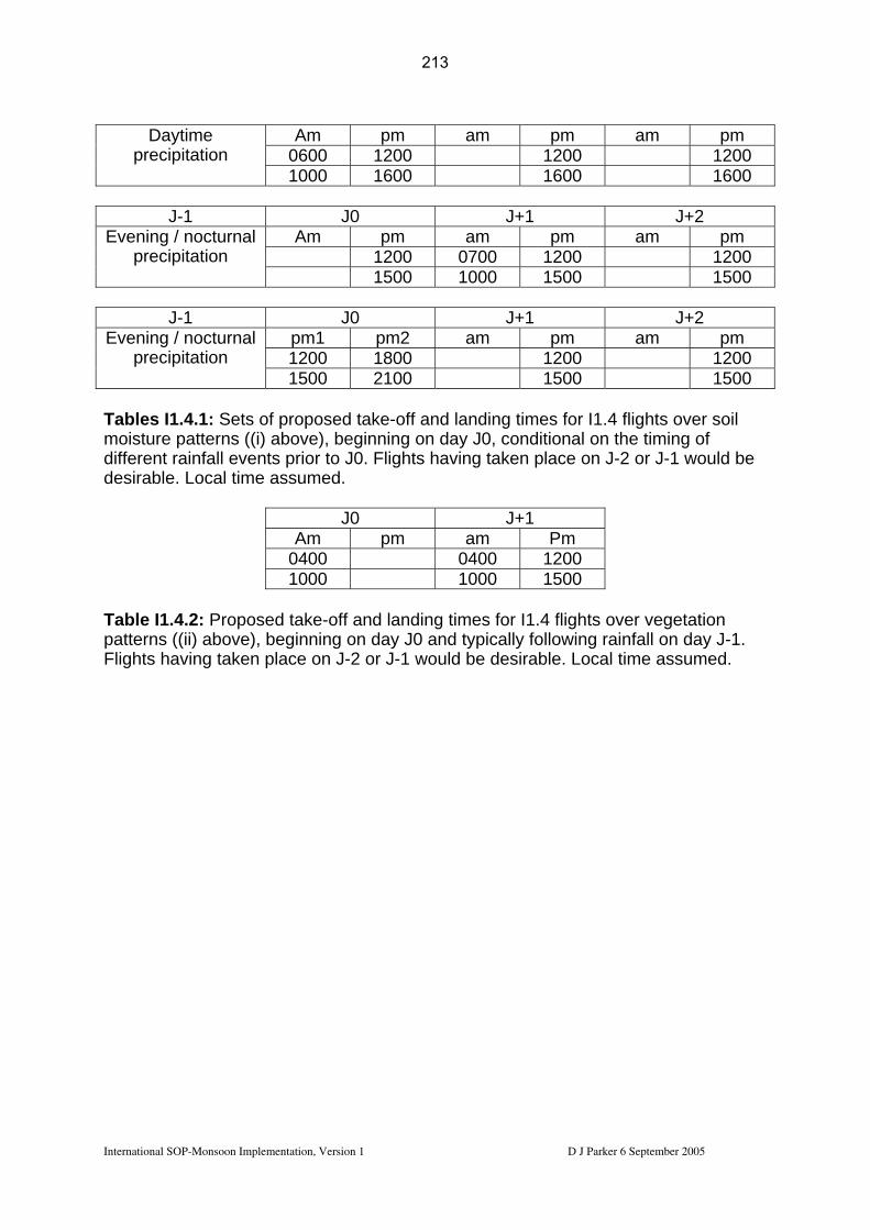
Am pm am pm am pm 0600 1200 1200 1200
Daytime precipitation
1000 1600 1600 1600
J-1 J0 J+1 J+2 Am pm am pm am pm
1200 0700 1200 1200 Evening / nocturnal
precipitation 1500 1000 1500 1500
J-1 J0 J+1 J+2
pm1 pm2 am pm am pm 1200 1800 1200 1200
Evening / nocturnal precipitation
1500 2100 1500 1500 Tables I1.4.1: Sets of proposed take-off and landing times for I1.4 flights over soil moisture patterns ((i) above), beginning on day J0, conditional on the timing of different rainfall events prior to J0. Flights having taken place on J-2 or J-1 would be desirable. Local time assumed.
J0 J+1 Am pm am Pm
0400 0400 1200 1000 1000 1500
Table I1.4.2: Proposed takatterns ((ii) above), begin
e-off and landing times for I1.4 flights over vegetation ning on day J0 and typically following rainfall on day J-1.
2 or J-1 woul ssumedpFlights having taken place on J- d be desirable. Local time a .
International SOP-Monsoon Implementation, Version 1 D J Parker 6 September 2005
213

3 hours; 1 low level leg
24 kft / FL240~ 400 hPa45 min ~ 270 km
30 mins
~ 1 hour
45 min ~ 270 km 500 ft
4 hours – 1 low level leg
500 ft
24 kft / FL240~ 400 hPa
75 min ~ 450 km
75 min ~ 450 km
30 mins
~ 1 hour
International SOP-Monsoon Implementation, Version 1 D J Parker 6 September 2005
214
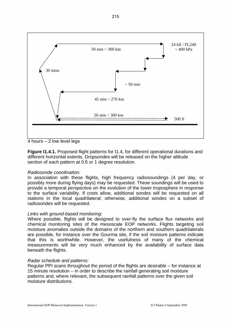
4 hours – 2 low level legs
50 min ~ 300 km500 ft
24 kft / FL240~ 400 hPa50 min ~ 300 km
30 mins
~ 50 min
45 min ~ 270 km
Figure I1.4.1. for I1.4, for different operational durations and different horizontal extents. Dropsondes will be released on the higher altitude section
Proposed flight patterns
of each pattern at 0.5 or 1 degree resolution.
adiosonde coordination: RIn association with these flights, high frequency radiosoundings (4 per day, or ossibly more during flying days) may be requested. These soundings will be used to
provide a temporal perspective on the evolution of the lower troposphere in response to the surface variability. If costs allow, additional sondes will be requested on all stations in the local quadrilateral; otherwise, additional sondes on a subset of radiosondes will be requested. Links with ground-based monitoring: Where possible, flights will be designed to over-fly the surface flux networks and chemical monitoring sites of the mesoscale EOP networks. Flights targeting soil moisture anomalies outside the domains of the northern and southern quadrilaterals are possible, for instance over the Gourma site, if the soil moisture patterns indicate that this is worthwhile. However, the usefulness of many of the chemical measurements will be very much enhanced by the availability of surface data beneath the flights. Radar schedule and patterns: Regular PPI scans throughout the period of the flights are desirable – for instance at 15 minute resolution – in order to describe the rainfall generating soil moisture patterns and, where relevant, the subsequent rainfall patterns over the given soil moisture distributions.
p
International SOP-Monsoon Implementation, Version 1 D J Parker 6 September 2005
215

Tethered balloon flights: e tethered balloons will, where possible, be deployed to
re dry and moist soil being situated at the tethered
he aircraft can
odelling: ill be used to evaluate models of:
s
d calibrate satellite analyses of soil moisture
of
en dry and moist
oundary layer flights with additional aircraft on the same track and the same
well as studying fine-scale (1-10 km) up to synoptic-scale variability in the land surface state. North-south legs will also be made
At (Hombori and) Niamey thcoordinate with the flights, as outlined in section 2.1.1.6. If soil moisture patterns asuitable, with a transition betweenballoon location, then tethered balloon flights in the absence of tbe made. MData from the flights w
• Soil moisture • Boundary layer response (dynamics and composition) to surface properties • Mesoscale dynamics, thermodynamics and transport through shallow
convection and horizontal advection Dropsonde profiles will be made at high horizontal resolution (0.5 to 1 degree) in order to initialise and drive models. Aircraft profile data will also be used, as well ahigh frequency local radiosonde data, to provide temporal evolution of the thermodynamic and wind profiles. Satellite data: Flights will be planned on the basis of satellite analyses of soil moisture distributions, tropospheric composition of biogenic chemicals, and rainfall distributions. Flight data will be used to evaluate andistributions and tropospheric composition of biogenic chemicals. Forecasting needs:
• MCS activity: to be avoided, over the coming flight days. • Soil moisture distributions in case (i): good cases will involve distinct zones
soil moisture anomalies, on scales of 100 km. In cases of large soil moistureanomalies, flights may target the transition zones betwesurface.
Opportunities for enhancement:
• If airborne soil moisture instruments can be flown, then far better analyses of the land-atmosphere interactions can be achieved.
• Bday will give far better information about the PBL response to the surface (dynamical and chemical, where compatible chemistry is possible).
I1.5: Vegetation emission surveys (SOP2-a2 – Reeves, Parker)
Long straight and level runs, mostly in the CBL, will be achieved with the UK BAe 146 to characterise the emissions from different vegetation, land surface and soil moisture regimes. The flights will also enable an assessment of the synoptic-scale variability in the boundary layer thermodynamic state. East-West legs will collect data long a particular climatic zone, as a
International SOP-Monsoon Implementation, Version 1 D J Parker 6 September 2005
216
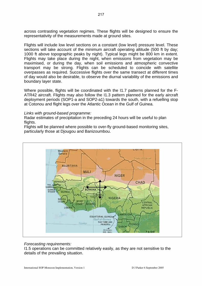
across contrasting vegetation regimes. These flights will be designed to ensure the
lights will include low level sections on a constant (low level) pressure level. These ccount of the minimum aircraft operating altitude (500 ft by day;
800 km in extent. lights may take place during the night, when emissions from vegetation may be
tmospheric convective ansport may be strong. Flights can be scheduled to coincide with satellite
required. Successive flights over the same transect at different times
representativity of the measurements made at ground sites. Fsections will take a1000 ft above topographic peaks by night). Typical legs might be Fmaximised, or during the day, when soil emissions and atroverpasses as of day would also be desirable, to observe the diurnal variability of the emissions and boundary layer state. Where possible, flights will be coordinated with the I1.7 patterns planned for the F-ATR42 aircraft. Flights may also follow the I1.3 pattern planned for the early aircraft deployment periods (SOP1-a and SOP2-a1) towards the south, with a refuelling stop at Cotonou and flight legs over the Atlantic Ocean in the Gulf of Guinea. Links with ground-based programme: Radar estimates of precipitation in the preceding 24 hours will be useful to plan flights. Flights will be planned where possible to over-fly ground-based monitoring sites, particularly those at Djougou and Banizoumbou.
Forecasting requirements: I1.5 operations can be committed relatively easily, as they are not sensitive to the details of the prevailing situation.
International SOP-Monsoon Implementation, Version 1 D J Parker 6 September 2005
217

International SOP-Monsoon Implementation, Version 1 D J Parker 6 September 2005
sampling can extend to:
Flights should take place in the absence of cumulonimbus activity. Estimates of CBL depth, soil moisture (see I1.4), soil temperatures (see I1.4), and emissions will be useful for planning the flight locations. Links with modelling: Model products will be used in an attempt to forecast / analyse areas of significant emissions (and emissions gradients). Such models will also be evaluated with the flight data. Satellite, radar and onboard radiometry will be used to analyse the cloud fields along the flight track, and to estimate the surface radiative fluxes for input to retrospective modelling studies. Attempts will be made to evaluate turbulent fluxes of those species which can be measured at high time-resolution (including water vapour) and these fluxes will be related to estimates obtained from research and operational models. Composition and emissions estimates will be used to refine and evaluate models of global atmospheric composition. Satellite requirements: If requested, these flights can be scheduled to coincide with the times of satellite overpasses. Recommendations for enhancement: If the I1.5 flights can be coordinated with the I1.7 flights of the F-ATR42, then
• Flights at 2 levels with the 2 aircraft; the BAe146 flying at a low level and the F-ATR42 flying in and around cloud base (of shallow cumulus);
• Flights at successive times during the diurnal cycle, to evaluate the diurnal variability in the boundary layer state and composition
I1.6: Urban surveys (SOP2-a2 – Parker, Lewis) Short surveys of large urban regions – e.g. box flights around Niamey, Lagos, Accra or Dakar may be performed with the UK BAe 146. The objectives of these flights would be to sample the effects of these large and growing urban regions on air quality. These flights would take place as opportunity flights, capitalising on the aircraft being in the vicinity, and have a duration of 2 hours or less. Flights would take place in the boundary layer and sample both the upstream and downstream conditions to make a first-order assessment of the urban impact on atmospheric composition. Proposed flight patterns would depend on the city in question, and the flight hours available. Typical flights might involve 2 stacked legs (one in and one above the boundary layer) on transects upstream and downstream of the city, or along-wind legs over and downstream of the city.
218
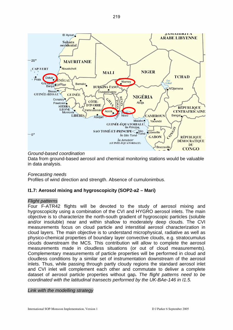
Dain
FoPr
Ground-based coordination ta from ground-based aerosodata analysis.
recasting needs ofiles of wind direction and str
I1.7: Aerosol mixing and hygr Flight patterns
ur F-ATR42 flights will bFo
anmeclophclouds downstream the MCS.
Cocloudless conditions by a simil
and CVI inlet will complement
co
hygroscopicity using a combinaobjective is to characterize the
d/or insoluble) near and wasurements focus on cloudud layers. The main objectivysico-chemical properties of
measurements made in cloumplementary measurements
inlets. Thus, while passing thro
dataset of aerosol particle proordinated with the latitudinal t
Link with the modelling strategy
International SOP-Monsoon Implementation, Versio
219
l and chemical monitoring stations would be valuable
ength. Absence of cumulonimbus.
oscopicity (SOP2-a2 – Mari)
e devoted to the study of aerosol mixing and
This contribution will allow to complete the aerosol
ed in cloud and ar set of instrumentation downstream of the aerosol
each other and commutate to deliver a complete flight patterns need to be
tion of the CVI and HYGRO aerosol inlets. The main north-south gradient of hygroscopic particles (soluble ithin shallow to moderately deep clouds. The CVI particle and interstitial aerosol characterization in e is to understand microphysical, radiative as well as boundary layer convective clouds, e.g. stratocumulus
dless situations (or out of cloud measurements). of particle properties will be perform
ugh partly cloudy regions the standard aerosol inlet
perties without gap. The ransects performed by the UK-BAe-146 in I1.5.
n 1 D J Parker 6 September 2005

Mecloud sensitwater
asurements of CN and CCN below the cloud base provide initial conditions for droplets activation models. The latitudinal transect will serve to test the
ivity of the cloud droplet nucleation to the emissions of gaseous precursors and vapor humidity gradient.
Ground-based cooperation Coordination with CCN measurements and aerosols precursors in Djougou (Benin). Forecasting requirements Preference for non-precipitating clouds. Forecast of the cloud base altitude needed. Vertical distribution of aerosols and cloud layer needed.
I2: Dynamics and chemistry of MCSs (SOP1-a, SOP2-a1, SOP2-a2 – Mari, Flamant, Reeves, Hoeller)
International SOP-Monsoon Implementation, Version 1 D J Parker 6 September 2005
220

Figure I4.1: Target zone during SOP2-a1 and SOP2-a2 Flight patterns for SOP2-a1 (1-15 July) During this period, the exploration of the mesoscale dynamics of MCSs and their environment will be made with 3 aircraft: the ATR42 in the PBL, the F/F20 as well as the D/F20. The two last aircraft will sample the environmental conditions around a MCS by means of dropsondes and lidar 2D fields (water vapour and wind) along with flight level measurements. During SOP-B2 we propose to conduct operations for 2 or 3 MCS cases. Operations hall not be tied either to the Niamey, but should be conducteds within the area
iosonde quadrilateral. The “generic” MCS plan is shown
i)
ii)
) and an of the
v)
delimited by the northern radin Fig. I2-1. The following conditions must be met:
ferry time from Niamey to initial point (1) - and from end point (16) to Niamey - must be less than 30 min, i.e. about 300 km range. This is also the time necessary to reach an altitude of 40 kft (12 km) ;
to optimize the flight strategy with respect to the MCS propagation (10-20 m/s or 35-70 km/h, toward NW to S), it is preferable to conduct airborne observations when the MCS is east of Niamey ;
iii) the way points are along an « outer octogon » (fixed diameter of 500 km« inner hexagon » (variable diameter of ≈200-300km, depending on the size considered MCS) ;
iv) optimum flight level is 40 kft, but it could be lowered to 35 or 30 kft, to avoid commercial traffic or to fly below cloud cover (for LEANDRE-2 and WIND operations during SOP-B2) ;
dropsondes must be released at each way point. With a fall speed of about 8 m/s, it takes about 25 min to reach the ground. During this period, the aircraft flying at 220 m/s
International SOP-Monsoon Implementation, Version 1 D J Parker 6 September 2005
221

covers a distance of about 330 km, during which a maximum of 4 dropsondes will be released due to the limitations of the 4-channel receiver ; the initial point can be (4) instead of (1), depending on the MCS location with respect to Niamey (instead of 1-2-3-4-5-6-7-8, the aircraft would then fly 4-3-2-1-8-7-6-5) ; the first leg (1-2-3-4) is to sample the upstream environment at about 150 km in front of the MCS, followed by a closer sampling (5-6-7-8) at 10-20 km (depending on flight safety) fom the MCS leading convective line ;
vi)
vii)
« GO / NOGO » decision must be taken concerning flight
int (11) should be within the stratiform cloud ;
e leg to sample the downstream environment at
xi)
d flight
ing SOP2-a1, the D/F20 equiped with WIND Doppler lidar should fly at same altitude and close distance from the French FA-20. Lidar measurements are not
nd the far downstream
e.
viii) at way point (8) a continuation : depending on MCS development - as seen on radar (if available) and satellite images - and flight safety from pilot's opinion, the aircraft should either fly around the southern edge of the MCS through way point (9) if safe, or return to Niamey if unsafe. In the later situation, the downstream part should be conducted during a following flight with (13) or (16) as initial point, most probably when the MCS has propagated west of Niamey ;
ix) leg (9-10-11-12) should be flown near the edge of the trailing stratiform anvil of the MCS . If possible, way po
x) leg (12-13-14-15-16) is a remotabout 150 km behind the MCS ;
coordinated flights with several aircraft would include : 1. during SOP2-a1 and 2-A2, the F/ATR will make in situ measurements in the low levels
(1 to 5 kft) : first flight will be upstream, along way points (1-2-3-6-7-8), seconafter refueling in Niamey will be downstream along way points (10-11-12-13-14-15) ;
2. dur
possible within cloudy air, so the upstream (1-2-3-4-5-6-7-8) a(13-14-15-16) parts of the flight must be in clear air.
The combination of LEANDRE 2 and WIND measurements around the MCSs will enable detailed, high spatio-temporal resolution analysis of the moisture inflow into
CSs for the first timM
International SOP-Monsoon Implementation, Version 1 D J Parker 6 September 2005
222

proposed aircraft designed to investigate
Figure I2-1: operations MSCs environment during SOP2-a1 and SOP2-a2.
Flight patterns for SOP2-a2 (17 July – 25 August 2006)
p to five aircraft (UK-BAe146, F-F20, D-F20, F-ATR42 and Geophysica) will be deployed. hree « small » MCSs (size less than 1-2°) and three large MCSs will be sampled
above different emission environments (two above the Sahel region north or close to Niamey in Niger, two above of the forest region close to Djougou in Benin). A possible target could be MCSs initiated over the Aïr mountains. Two (potentially four) MCSs will to studied in coordination between the chemistry and the dynamics with simultaneous measurements of airmass chemical composition and environmental conditions with dropsondes (about 20 dropsondes/flights for the F-F20 and the UK-BAe-146). The F-ATR42 and the UK-BAe-146 have instrumentation for making aerosol measurements and turbulent air motion measurements. Because of these payloads and operational characteristics, the F-ATR42 flights will emphasize process-oriented studies associated with aerosol properties and ozone photochemistry and include boundary layer investigations and the UK-BAe146 will explore the meteorological, aerosol and chemical characteristics of the mid-tropospheric dry air layer that feeds the MCSs, between 3 and 7 km. Two (potentially four) MCSs will be sampled with the UK-BAe146 depending on the MCS development (one flight around if safe, two flights east and west if unsafe). The F-
UT
International SOP-Monsoon Implementation, Version 1 D J Parker 6 September 2005
223

F20 will characterize the ozone photochemical precursors and dynamics in the upper troposphere, near the MCSs. Adaptative flight plans are proposed depending on the MCS development and security recommendations. The F-F20 should either fly around the MCS or return to Niamey during day 1 (GO/NOGO decision). In case, the F-F20 returns to Niamey, measurements in the downstream part will be conducted on the morning of day 2 once the MCS has propagated west of Niamey or Djougou. Ideally, the Geophysica high altitude aircraft, based in Ouagadougou, will make measurements above cumulonimbus cloud turrets during their development phase in late afternoon and early evening. The number of flight hours for the Geophysica is not yet secured. Link with the modelling strategy: The proposed flight plans will provide 3D observations of the MCS environment. Vertical distributions of dynamical and chemical parameters will be constructed from measurements in the boundary layer inflow, in the mid-tropospheric dry layer and in the upper tropospheric outflow regions. Dropsondes will provide the main structure of
vailable from the SCOUT balloons during the night and the Geophysica aircraft uring daytime, for comparison with trajectory or Eulerien models.
the flows close to and downstream of the MCSs. These measurements will be compared with simulated MCS developments and impacts at the local, regional and global scale. Flights performed before the MCS passage measure the dynamical and chemical conditions to initialize the high resolution and mesoscale models. Flights performed after the MCS passage measure the perturbed environment to compare with model outputs. Additional measurements in the TTL above the MCSs will be ad Ground-based cooperation: Coordination with driftsondes being released from N’Djamena (targeting experiments of MCSs and their environment). Coordination with ground sites along the flight pattern at Djougou (Benin) and Banizoumbou (Niger). These two sites will operate in the EOP mode for the aerosol and chemistry measurements (see recommendations for enhancement). The IOP will also benefit from the ozonesondes in Niamey (SCOUT EU program) and Cotonou (French and EU projects) Coordination with the radiosonding network – additional soundings to be requested in the northern or southern quadrilateral as permitted by logistical constraints – up to 8 per day. Coordination with the SCOUT balloon campaign to further study the convective
cirrus clouds and chemical composition
ll be released as soon after the MCS event as is scend slowly through the TTL region in
tflow of a system whose upstream and
vertical transport, the water vapor budget, of the TTL region in the vicinity of MCS events. Small balloons will be deployed during SOP2-a1 and SOP2-a3 including measurements of water vapor, ice and aerosols distribution, remote and in-situ chemistry (BrO/NO2/O3), short lived organic bromine. The balloons wipractically possible and will be timed to dethe following hours, sampling the oudownstream tropospheric environment is to be observed with the BAe146. Theimpact of these balloons will be enhanced by the provision of high frequency radiosondes within the flight region.
Forecasting requirements
International SOP-Monsoon Implementation, Version 1 D J Parker 6 September 2005
224

The success of t iggering east of
speed, humidity
Niamey and on t zone. Forecast of aer ill discriminate between emissio regions. The decision-m near-real time forecasting base (surface wind
Recomm
chlager and K. Law).
downwind from emissions by coordinated fligh
endatioRadar operati l structure and evolution of th n the dynamics of the MCSs to and precursors Ground-based P2-a2. Additional flig
I3: Long range t
The aim is to ch ses transported
Flight patterns I3.1: Long-rangeaircraft Geophys146. Both the G(Burkina Faso). aerosols at consuitcase flight toperform science program. I3.2: Large-scaleaerosols will be sF20 and the Geothe previous daOuagadougou wOuémé but withMCSs.
International SOP-Monsoon
225
he mission relies strongly on the prediction of MCS tr
profiles).
he MCSs tracking and development within the target osol and gases venting plumes and trajectories wns by the vegetation and low emissions over sahelianaking for TTL small balloons mostly relies on d on radar (cloud/no cloud) and radiosoundings
H. S
convective regions and large-scale impact of WAM
ns for enhancement: on needed in Niamey to document the 3D dynamicae sampled MCSs. It is essential to have information o understand the redistribution and aging of aerosols measurements in the SOP intensive mode during SOht hours for the Geophysica (see report from
ransport surveys (SOP2-a2 – Reeves, Mari)
aracterize trace gas and aerosol evolution in air mas
ts.
transport (Fig. I3.1). Four aircraft will be deployed: the high altitude ica, and the mid-level altitude aircraft D-F20, F-F20 and UK-Bae-eophysica and D-F20 aircrafts will be based on Ouagadougou
For the sampling of long-range transport of ozone precursors and tinental scale, the UK-BAE-146 will operate from Niamey with a
over Niamey or Ouémé (Figure I3.2) or MCSs westward of
Dakar (longitudinal transect). Once in Dakar, the UK-BAe-146 will flights within and below dust layers in coordination with the DODO
MCS impacts (Fig. I3.2). The aging of ozone precursors and tudied by sampling MCSs with similar flight patterns to I2 with the D-physica. The target MCSs will be either specific MCSs sampled in
ysith no direct connection with the MCSs sampled over Niamey and environmental conditions perturbed by earlier passage of several
Implementation, Version 1 D J Parker 6 September 2005
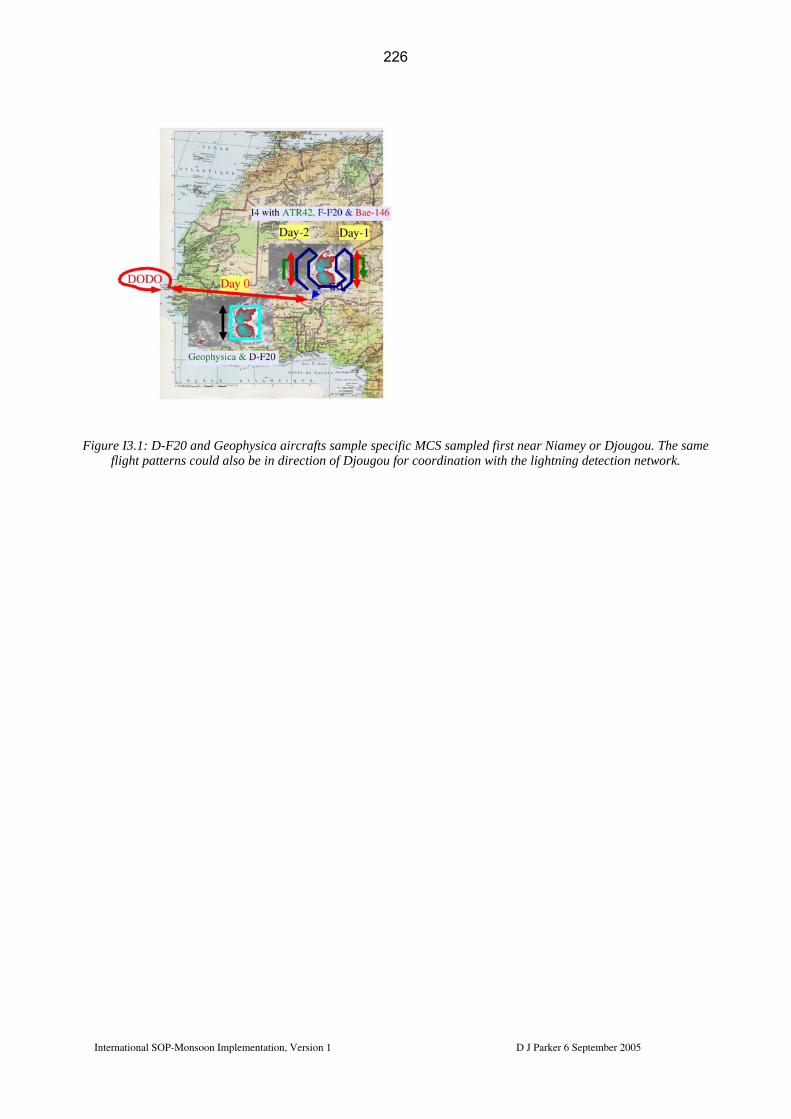
Figure I3.1: D-F20 and Geophysica aircrafts sample specific MCS sampled first near Niamey or Djougou. The same flight patterns could also be in direction of Djougou for coordination with the lightning detection network.
International SOP-Monsoon Implementation, Version 1 D J Parker 6 September 2005
226

International SOP-Monsoon Implementation, Version 1 D J Parker 6 September 2005
Link with the modelling strategy Tracking of MCSs over a 2-3 days periods will allow to document the ozone and aerosols aging at the continental scale. This experiment extends the temporal and spatial windows of the MCSs exploration proposed in I2 and will be used mainly for global modelling of WAM impacts on aerosols and chemistry. The synergy between the proposed flights and the global modelling community needs to be refined. In particular, it may be needed to have more extended latitudinal and longitudinal transects at high altitude for comparison with the global models outputs. Ground-based cooperation Flights will be coordinated with the lightning detection network over Djougou and balloon launches near Niamey. Forecasting requirements The same products than those listed for I2 have to be available at the secondary AOC in Ouagadougou. In particular, the MCSs tracking forecast is of prime importance for the I3.1 experiment. Recommandations for enhancement: Additional flight hours for the Geophysica Additional soundings along the zonal transect (N’Djamena, Niamey, Bamako, Dakar, Sal if possible) and possibly the northern stations at Agadez and Tomboucou; up to 4 per day.
Figure I3.2: Sampling of the chemical and aerosol composition in outflow regions of the MCSs in the UT, TTL and possibly stratosphere.
227
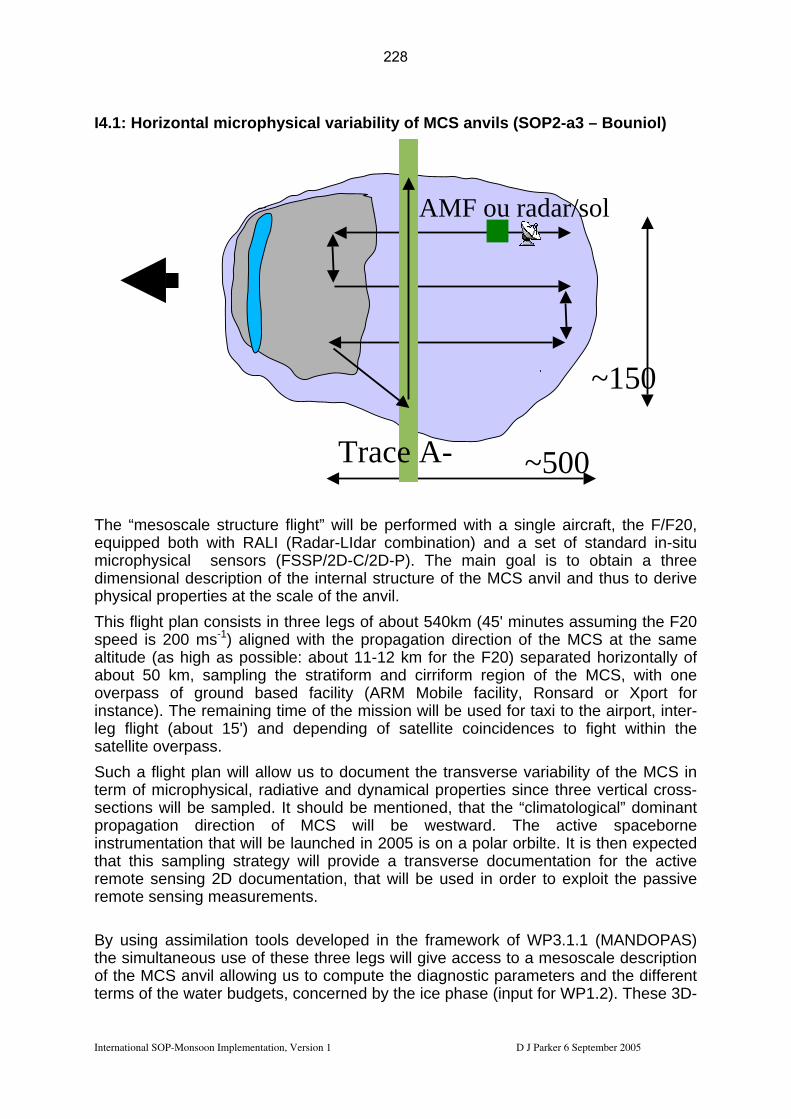
I4.1: Horizontal microphysical variability of MCS anvils (SOP2-a3 – Bouniol)
T “ osca struct l ormed with a single aircraft, the F/F20,
both ith RA I a Idar bination) and a set of standard in-situ microphysical sensors (FSSP/2D-C/2D-P). The main goal is to obtain a three
nsiona scription f t ure of the MCS anvil and thus to derive l pr rties at the s le of e anv
This flight plan consists in three legs of about 540km (45' minutes assuming the F20 speed is 200 ms-1) aligned with the propagation direction of the MCS at the same altitude (as high as possible: about 11-12 km for the F20) separated horizontally of
50 , sampling the stratiform a cirriform region of the MCS, with one overpass of ground based facility (ARM Mobile facility, Ronsard or Xport for in nce). remaining time of the miss will be used for taxi to the airport, inter-
ht ( out 15') and depending o tellite coincidences to fight within the overpass.
uc ht plan will w us to document the transverse variability of the MCS in f ic p ,
l be sample It should be m oned, that the “climatological” dominant propagation direction of MCS will be westward. The active spaceborne
on a polar orbilte. It is then expected amp stra will p vide ansverse documentation for the active
remote sensing 2D documentation, that will be used in order to exploit the passive en t
By using assimilation tools developed in framework of WP3.1.1 (MANDOPAS) simulta ou o e s give access to a mesoscale description
of the MCS anvil allowing us to compute diagnostic parameters and the different terms of the wate dgets, concer ice phase (input for WP1.2). These 3D-
P
~500
~150
Trace A-
AMF ou radar/sol
heq
e ui
mesped
le w
ureL
flig(R
htd” war-
ilL
be perfcom
ructil.
nd
ionf sa
enti
a tr
the will the the
p
dimephysica
l deope
o theca
intern th
al s
about km
staleg fligsatellite
Theab
Sts
h a oions
flig m wil
alloradd.
ermect
ro hysical iative and dynamical properties since three vertical cross-
instrumentation that will be launched in 2005 is that this s ling tegy ro
remote s
sing measuremen s.
the ne s use f thes three leg
r bu ned by
International SOP-Monsoon Implementation, Version 1 D J Parker 6 September 2005
228
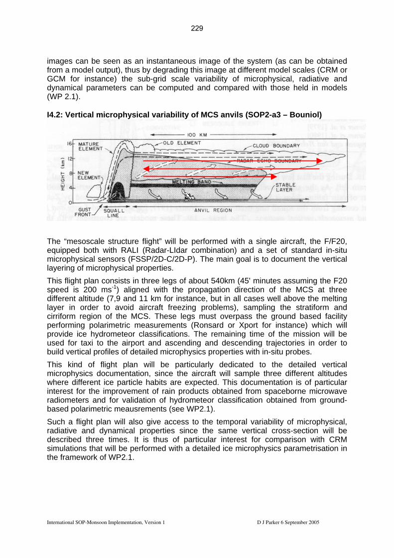
images can be seen as an instantaneous image of the system (as can be obtained from a model output), thus by degrading this image at different model scales (CRM or GCM for instance) the sub-grid scale variability of microphysical, radiative and dynamical parameters can be computed and compared with those held in models (WP 2.1). I4.2: Vertical microphysical variability of MCS anvils (SOP2-a3 – Bouniol)
The “mesoscale structure flight” will be performed with a single aircraft, the F/F20, equipped both with RALI (Radar-LIdar combination) and a set of standard in-situ microphysical sensors (FSSP/2D-C/2D-P). The main goal is to document the vertical layering of microphysical properties. This flight plan consists in three legs of about 540km (45' minutes assuming the F20 speed is 200 ms-1) aligned with the propagation direction of the MCS at three different altitude (7,9 and 11 km for instance, but in all cases well above the melting layer in order to avoid aircraft freezing problems), sampling the stratiform and cirriform region of the MCS. These legs must overpass the ground based facility performing polarimetric measurements (Ronsard or Xport for instance) which will provide ice hydrometeor classifications. used for taxi to the airport and ascending and descending trajectories in order to build vertical profiles of detailed microphysics properties with in-situ probes. This kind of flight plan will be particularly dedicated to the detailed vertical m where different ice particle habits are expected. This documentation is of particular interest for the improvement of rain products obtained from spaceborne microwave radiometers and for validation of hydrometeor classification obtained from ground-based polarimetric meausrements (see WP2.1). Such a flight plan will also give access to the temporal variability of microphysical, radiative and dynamical properties since the same vertical cross-section will be described three times. It is thus of particular interest for comparison with CRM simulations that will be performed with a detailed ice microphysics parametrisation in the framework of WP2.1.
The remaining time of the mission will be
icrophysics documentation, since the aircraft will sample three different altitudes
International SOP-Monsoon Implementation, Version 1 D J Parker 6 September 2005
229

I5: Intensive regional observations It has been proposed to make an intensive set of regional observations over a relatively short period of time during SObe used for a dense data assimilation exerweather prediction (NWP models). The impacevaluated retrospectively in ‘data denial’ testMeteorol. Soc.). Such studies could be performed as a basic with prediction of high-impacas hurricanes, or possibly of dry spells in the Sahel. Other measurements would be used to Observations which could be included in such intensive studies would be:
• Radiosondes;
P 1 and/or SOP2. These observations would cise in global and regional numerical
t of different data streams can then be s (e.g. Tompkins et al, 2005, Q. J. R.
data impact evaluation, or in association t weather (the theme of AMMA Working Group 5) such
evaluate the model performance.
• Targetted dropsondes – released in data-sparse areas or in areas identified through objective targeting techniques, such as singular vector computations;
• Driftsondes; • GPS water vapour systems; • UHF and VHF wind profilers.
International SOP-Monsoon Implementation, Version 1 D J Parker 6 September 2005
230

International SOP-Monsoon Implementation, Version 1. D J Parker 9 September 2005
IOP pattern
I1.1: ITF and Heat
I1.2: Dry
I1.3: N-S Land-Ocean- Atmosphe
I1.4: Land-
s
I1.5: Vegetation
Surv
I1.6: Urban Surys
I1.7: Aerosol Miand Hy
I2: Dynamics
Chemistryof MCSs
I3: Long Range
I4.1: MCSs
e Structure
I4.2: MCSs
calLow Surveys
SquallLine Passage
re Interactions
atmoere
ph Emission eys
ve xing
groscopicity
and
Transport Mesoscal VertiStructur
e
BAe146 NERC EU NERC NERC?
NERC EU
ATR API API API API API API F-F20 API API API API API API API D-F20 EU EU EU A
irc
Geophysica
raft
Hombori Yes le ossible Yes Possible Possible Possible
Possib Possible No Yes P
Niamey Yes Possle
Y ossibl Ye es Yes Yes Yes Possible ib es P e s Y
Oueme No No Y s ossibl Yes Possible Possible No Yes Possible e P eShips No No Possible Yes No No No Yes No ?? Radiosondes
Yes Yes Ye Yes Ye Ye es Yes Yes Yes s s s YCoo
rdin
atio
n
SCOUT No No No Possible No No No SOP2-a2 Possible No
Table 2.4a: Instru e so cale tes, nd funding sources for different IOP patterns. ments, intensiv s si ame
231

International SOP-Monsoon Implementation, Version 1. D J Parker 9 September 2005
I1.1: ITF and I1.2: Dry
Interactions
I1.4:
ere
I1.5:
Surveys
I1.6:
s
e
Hygroscopicity
I2: Dynamics and Chemistry of MCSs
I3: Long Range Transport
I4.1: MCSs Mesoscale Structure
I4.2: MCSs Vertical Structure
IOP pattern Heat Low
Surveys Squall Line
Land-Ocean- Atmosphere
Land-atmosph
Vegetation Emission
Urban Survey
Mixing and
Passage
I1.3: N-S I1.7: A rosol
1.1.1 1.1.2 1.1.3 1.3.1 1.3.2 1.3.3 2.1.1 2.1.2 2.1.3 A
MM
A-E
U
2.4.1 2.4.2 2.4.3 2.4.4 1.3 1.4 2.1 2.2 3.1 3.2 3.3 3.4 3.5 4.1 4.2 4.3 4.4
AM
MA
-UK
5.1 1.1.1 1.1.2 1.1.3 1.3.1 1.3.2 1.3.3 2.1.1 2.1.2 2.1.3 2.1.4 2.1.5 2.1.6 2.4.1 2.4.2 2.4.3
AM
MA
-Fra
nce
2.4.4
232

Table 2.4b: Scientific stakeholders for different IOP patterns
International SOP-Monsoon Implementation, Version 1. D J Parker 9 September 2005
233

.1 1.2 1.3 1.4 2.1 2. 3.4 4.1 2 4.3 4.4
Oceanic instrumented mast OS.Mat_SAG_E
Instrument Code 1 2 2.3 2.4 3.1 3.2 3.3 4.
X X X X X X
Flux station AS.Flux_ X X D X X Radiosounding Dano X AS.Rs_D X X X X X X X X Drif D _tsondes AS. rift_T1 E x x x X Constant volume balloon AS.B T2 x x X x VC_ _E X
Oceanic sou OS.RS_SAG_E x ndings x x X X
Lidar AS.TRESS_Tam_ X E X X X
Lidar ar_Mbour AS.lid X X X X Lidar CCT25K 25K eilometer AE.CT X X X X
Micropulse lidar ( X X X MPL) X Wet and dry AS.Dust.ST_flux X X X X X deposition fluxes, etc.. Aerosol characteristion X X X X X Chemical instrument X AS.DUST_Od ation X C-Band Radar Ronsard
AS.RonsaE rd_O_ X X X X X X
Micr AD o Rain Radar AE_R K_T X X X X X Bistat. Radar (Wind field)
A AS_R_O
BIST.R DA X X X X X Lightning detection network X X X X
Sodar ne AE DAR X X twork .SO _ X Microwave Radiometer AE OF_ X .PR T X X X X X
GPS humidity S_1 AS.GP X X X X X GPS humidity AS.GPS_2 X X X X X GPS humidity AS.GPS_3 X X X X X
International SOP-Monsoon Implementation, Version 1. D J Parker 9 September 2005
234

Tethered balloon X X Table 2.4c: Scientific stakeholders for different SOP ground-based instruments: AMMA-EU only
Instrument Cod 1.1 1.2 1.3 1.4 2.1 2.2 2.3 2.4 3.1 3.2 3.3 3.4 4.1 4.2 4.3 4.4 Radiosoundings Net
e work X X X X X X X X
Ozone soundings AS.RSO3_Od_ E X X
X-Band pol. Radar A X X X AS_R DX_O X X X Table stak older or diff ent EOP-SOP ound-based i trume : AM A-EU onl 2.4d: Scientific eh s f er gr ns nts M y
International SOP-Monsoon Implementation, Version 1. D J Parker 9 September 2005
235

2.5 Lis f sites, instrum Instruments mount on af s n t A i ent.
Name sonds
r tatp
t o ents
ircr
n
and relevant m
t, and ground-ba
aps
ed ied
De
a
scriptio
struments are lis
Logistics
ed in the
Drope
ppend
Noctu
ces to this d
nal? Scientist in
Charge
Ins
Ap
ocum
umenion: endi
t
xUK BAe 146
2
0 f bottom of 2 hours) ove
d (daytime), raphy
0 ut 4.5 hours,
Flyr -3u o ? Pt
Wingspan: 26Length: 31 m Height: 8.61 Weight: 44.2 Take off distaTypical opera
.34 m
t nce: 16ting spe
00 med 2 0 kts
Max Altitude: 35 00Min Altitude: 50 ft (profile) 100 ft (up tosea, 500ft over lan1000ft above topog(nighttime). Range: about 3,50km,Endurance: abo
ing crew: 21 ound Crew: 2el load: 12000nsumption: ?U: 60 kva
her:
136 Yes Reeves Appendix
r
GFCGO
kg l/h
A3
French ATR42
k
urs Flyr
Pt
?? Appendix Wingspan: 24Length: 22.67Height: 7.59 Weight: 16.9 Take off distaTypical opera
.57 m m
t nce: 10ting spe
40 med ? ts
Endurance ~ 5 ho
ing crew: 11 ound Crew: 3
Fuel load: 3500 l Consumption: ?? l/h
U: 28 kva her:
N/A NoA2 G
GO
French Falcon F-F20
.3 m
nc in k
urs Flyr
Pt
Wingspan: 16Length: 18.30Height: 5.40 Weight: 14.5 tTake off distaTypical operat
1 m
e: 14g spe
00 med ?
ing crew: 6 ound Crew: 3
Fuel load: ?? 4130 kg Consumption: ?? l/h
U: 28 kva her:
280 – 320 sReque ted ?? Appendix
ts
Endurance ~ 4.5 hoG
GO
A1
German Falcon D-F20
rs ?? Appendix N/A No.Same as F/F20 Endurance ~ 4 hou . A4 Geophysica h u
t ngra ayt na
0 uk Vr i a o (17
urs The M-55 Geopturbofan aircraf21 km and can tup to 2300Kg. Ipayload of 150altitude of 17.5 are available fooperations. Hasoperative radiuskm altitude)
ysica with anspor
has a Kg anm andnstru maxif 350
is a d ceilit a pnomid a cr 60 K
ment mal 0 km
al of load l ise A
Endurance ~ 5.5 ho N/A No ?? Appendix A5
Table 2.5.1: onsoon. The number of dropsondes is based on a cost of 0.78 k€, will depend
Basic operational details of aircraft to be deployed in SOP-Mon the negotiated dropsonde cost.
International SOP-Monsoon Implementation, Version 1. D J Parker 9 September 2005
236
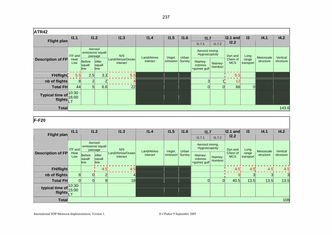
ATR42 I1.7 Flight plan
I1.1 I1.2 I1.3 I1.4 I1.5 I1.6 I1.7.1 I1.7.2
I2.1 and I2.2
I3 I4.1 I4.2
Aerosol emissions/ squall
passage
Aerosol mixing. Hygroscopicity
Description of FPITF and
Heat Low Before
squall line
After squall line
N/S Land/Atmos/Ocean
interact
Land/Atmos interact
Veget. emission
Urban Survey Niamey-
cotonou +guinee gulf
Niamey-Hombori
Dyn and Chem of
MCS
Long range
transport
Mesoscale structure
Vertical structure
FH/flight 5.5 2.5 3.3 5.5 5.5 nb of flights 8 2 2 4 3 1 12
Total FH 44 5 6.6 22 0 0 66 0
Typical time of flights
10:30 - 16:00 LT
Total 143.6
F-F20
I1.7 Flight planI1.1 I1.2 I1.3 I1.4 I1.5 I1.6
I1.7.1 I1.7.2
I2.1 and I2.2
I3 I4.1 I4.2
Aerosol emissions/ squall
passage
Aerosol mixing. Hy ity groscopic
Description of FPITF and
Heat Low Before
squall line
After squall line
N/S Land/Atmos/Ocean
interact
Land/Atmos interact
Veget. emission
Urban Survey Niamey-
cotonou +guinee gulf
Niamey-Hombori
Dyn and Chem of
MCS
Long range
transport
Mesoscale structure
Vertical structure
FH/flight 4.5 4.5 4.5 4.5 4.5 4.5nb of flights 8 0 2 4 9 3 3 3
Total FH 0 0 9 18 0 0 40.5 13.5 13.5 13.5
typical time of flights
10:30-15:00 LT
Total 108
International SOP-Monsoon Implementation, Version 1. D J Parker 9 September 2005
237
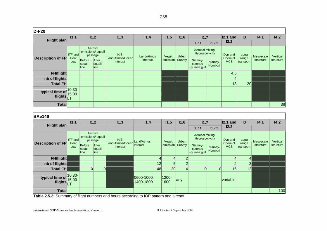
D -F20 I1.7 Flight plan
I1.1 I1.2 I1.3 I1.4 I1.5 I1.6 I1.7.1 I1.7.2
I2.1 and I2.2
I3 I4.1 I4.2
Aerosol emissions/ squall
passage
Aeroso ngl mixi . Hygro itscopic y
Description of FPITF and
Heat Low Before
squall line
After squall line
N/S Land/Atmos/Ocean
interact
Land/Atmos interact
Veget. emission
Urban Survey Niamey-
cotonou +guinee gulf
Niamey-Hombori
Dyn and Chem of
MCS
Long range
transport
Mesoscale structure
Vertical structure
FH/flight 4.5 nb of flights 4
Total FH 18 20
typical time of flights
10:30-15:00 LT
Total 38
B Ae146 I1.7 Flight plan
I1.1 I1.2 I1.3 I1.4 I1.5 I1.6 I1.7.1 I1.7.2
I2.1 and I2.2
I3 I4.1 I4.2
Aerosol emissions/ squall
passage
Aerosol mixing. Hygroscopicity
Description of FPITF and
Heat Low Before
squall line
After squall line
N/S Land/Atmos/Ocean
interact
Land/Atmos interact
Veget. emission
Urban Survey Niamey-
cotonou +guinee gulf
Niamey-Hombori
Dyn and Chem of
MCS
Long range
transport
Mesoscale structure
Vertical structure
FH/flight 4 4 2 4 4 nb of flights 12 5 2 4 3
Total FH 0 0 48 20 4 0 0 16 12
typical time of flights
10:30-15:00 LT
0600-1000, 1400-1800
1200-1600 any variable
Total 100Tabl m flight numbers and hours ac ing to IOP pat and aircrae 2.5.2: Su mary of cord tern ft.
International SOP-Monsoon Implementation, Version 1. D J Parker 9 September 2005
238

International SOP-Monsoon Implementation, Version 1. D J Parker 9 September 2005
.6.1 Determining priorities for the operational decision-making
Ps. tween the sets of funded objectives.
2.6 Observational priorities 2 A set of contingency plans will be based on operational conditions, for example:
• Dry spell measurements • Active AEWs • Active MCSs
Each of these sets of conditions leads to a set of possibilities according to science area. The decision-making protocol (section 3.1 below) outlines the way in which operational conditions will influence the deployment of resources during the SOPriorities for the IOPs must be balanced beFunding for IOPs is outlined in the IOP tables. We need to be able to respond to requests for additional ‘opportunistic’ activities (see 5c below). 2.6.2 Priorities for enhancement of the SOP activities 2.6.2.1 Radar at Niamey (Protat) The provision of radar at Niamey has been identified as a major priority for the SOP-Monsoon programme, as described in section 2.2.1.3 above. Every effort is being made to obtain and to fund a C-band radar at Niamey. 2.6.2.2 Scientific exploitation of the transit flights from Europe to Africa (Flamant) Flight patterns In the framework of the AMMA SOP, a large number of transit flights are scheduled between Europe and Africa, associated with the different deployment phases (Table 1). Because the air traffic routes cover a large part of the northern African continent, north of the AMMA domain, where data are sparce, the transit flights have been identified as potentially very valuable to enhance understanding of meteorological and radiative processes in the saharan heat low (SHL) region. Over the African continent, two major routes have been identified (Fig. 1):
1. Agadir – Niamey which will be dedicated to the study of the ‘heart’ of the SHL and the inter-tropical front (ITF),
2. Algiers – Niamey via Tamanrasset which will be dedicated to the study of dry intrusions in addition to that of the eastern part of the SHL and the IFT. Decision to follow this route will pend on the dry intrusion forecasts performed at IPSL or CNRM, and will also be constrained by the departure date alloted for the aircraft transit.
239

International SOP-Monsoon Implementation, Version 1. D J Parker 9 September 2005
OP F/F20 F/ATR UK/BAe D/F20 Geophysica S
42000 ft Creil -> Niamey
25000 ft Francazal -> Niamey
35000 ft Cranfield -> Niamey
42000 ft Oberpfaffenhofen -> Niamey/Ouaga
Oberpfaffenhofen -> Ouaga
0-a Lidar LNG Dropsondes In situ Round-trip
In situ Aerosol Round-trip
Dropsondes In situ Aerosol Chemistry Return via Dakar
N/A N/A
1-a Lidar L2 Dropsondes In situ Round-trip
In situ Aerosol Round-trip
N/A N/A N/A
2-a1 Lidar L2 Drop
In situ N/A To Niamey N/A sondes
In situ Round-trip
Lidar WIND In situ
Round-trip Round-trip 2-a2 Dropsondes
In situ Aerosol Chemistry Round-trip
In situ Aerosol Chemistry Round-trip
Dropsondes In situ Aerosol Chemistry Roun
To Ouaga In situ Aerosol Chemistry
In situ Aerosol Chemistry
d-trip Round-trip Round-trip 2-a3 Radar/Lidar
Dropsondes In situ Possible return via Dakar
N/A N/A N/A N/A
TaOu . Measurements that can only be acquired if the aircraft is flying at
ble 1: Instruments to acquire data along transit routes from Europe to Niamey or agadougou
scientific speed appear in italic.
Standard airborne in situ, dropsonde and remote sensing measurements may be acquired at both transit and scientific speed. In situ sampling of chemistry and aerosol will only be possible if the aircraft operate at scientific speed. Of great interest to the objectives persuied on each route are (1) the high resolution profiles of standard meteorological variables obtained from dropsondes and (2) the high vertical resolution atmospheric reflectivity, wind and water vapor profiles derived from lidars. Provided that aircraft fly at scientific speed, in situ chemical and aerosol sampling will be extremely valuable in the context of dry instrusions. A minimum number of 10 dropsondes should be released over the African continent during the transits by F/F20 and UK/BAe.
240

Figure 1: Transit routes for the F/F20 from Creil to Niamey, going through Agadir (western route) or Algiers (eastern route).
During SOP 0-A, two dropsonding aircraft shall transit to Niamey on the same day. In this case, coordinated exploration of the lower troposphere along the two routes will be of great interest. Similarly, during SOP 2-a2, two aircraft equipped with downward pointing lidars (F/F20 with LEANDRE 2 and D/F20 with WIND) will also travel to Africa on the same day. Coordinated exploration of the lower troposphere along the two routes will be of great interest, especially if the D/F20 releases dropsondes for the occasion. Link with the modelling strategy Measurements acquired on these transects will provide a high-quality set of observations for improving the representation the heat low dynamics and the impact of aerosol radiative forcing in numerical simulations and meteorological analyses, in a region where observations are scarce. Link with satellite observations Real-time tracking of mesoscale convective systems (MCSs) as aircraft should stay away from them. Ground-based cooperation Coordination with the Tamarasset Supersite for aircraft transiting through Algiers and Tamanrasset (eastern route).
International SOP-Monsoon Implementation, Version 1. D J Parker 9 September 2005
241

Forecasting requirements
ry intrusions
he Saharan heat low (SHL) region is key to understanding the monsoon dynamics. The Hcharacterized as a region of high surface albedo, overlain by strong synoptic sub hen heated in the Sa an aerosol layer (SAL). The presence of the dust layer combined with the high soil temunique destabilization factor for t
w over the Saharan desert is an
pressures in this zone are critical to driving the ft and Blackburn). Indeed, Parker et al. (2005)
pkins et al 2005) and shows (from satellite
udget, cloud cover) and features refore, observations of actual fluxes and
g l D to s n ation to the north of th O05°31'E). Instrumentation here includes broadband radiometers, sun photometer and t ra f vertical rofiles of the boundary layer, clouds and aerosols. However, this station is
. and radiometers in the heat low
one, perhaps at the synoptic station of Tessalit (Mali).
Position of the SHL and of the ITF DPosition and height of the african easterly jet 2.6.2.3 Surface flux measurements in the heat low region (Parker) T
S L is roughly defined as the region 20°-30°N, 15°W - 10°E. The SHL can be
sidence, where dry convection dominates. Mineral dust in the atmosphere w by shortwave solar radiation absorption presents a secondary heat sourceharan planetary boundary layer, also sometimes refered to as the Sahar
perature which is controlled by the earth’s surface heat balance, constitute a he Saharan desert mixed layer.
The thermodynamic budget of the thermal lo
portant element of the climate of the West African region. It has recently been imargued that the temperatures and
hole monsoon system (Thorncrowshow a good correlation between monsoonal winds at Niamey and the surface temperatures at 21.5N. Thus, the intensity of southerly/southwesterly monsoon flow (including the sudden surge associated with the so called “jump” or onset) is partly controlled by the intensity of the SHL. Variability in the fluxes in this region is strongly
lated to aerosol loading (e.g. Tomremeasurements) intraseasonal variability. Despite its central role, the very little is known on the dynamics of SHL including the diurnal and seasonal evolution of its main characteristics (position, horizontal extend, ubsidence aloft, thermodynamic budget, radiative bs
(SAL, inter-tropical front -ITF). Theth oerm dynamic properties of this zone are required, in order to test and develop loba and theoretical models. ue the logistical constraints of working in the heat low zone, a full EOP fluxtatio in this zone was not feasible. Within AMMA, instrumente E P surface flux networks is focussed on the Tamanrasset ‘Supersite’ (22°47'N,
he T nsportable Remote Sensing Station (TreSS) for observations opinfluenced by nearby topography and is rather north and east of the peak heat lowWe therefore wish to make efforts to deploy broad-bz
International SOP-Monsoon Implementation, Version 1. D J Parker 9 September 2005
242

2.6.2.4 Airborne soil moisture measurements (de Rosnay) Soil moisture remote sensing is a key component of AMMA project. It provides spatially integrated information on soil moisture at a scale relevant for atmospheriprocesses. METOP/ASCAT will provide soil moisture estimates for 2005-2007 from active measurements. AMSR microwave passive measurements has been providing soil moistur
c
e products since 2002. SMOS measurements for 2007-2010 period is xtremely relevant to AMMA project to enhance the quality of soil moisture products
t region where SMOS is expected have a major scientific feedback and crucial innovative applications for seasonal
y ture products and inversion algorithms at
different spatial scales along a strong climatic gradient and for several annual cycles. The aim of validation studies over AMMA is to use both ground measurements and land surface modelling approaches to compare and validate SMOS products over West Africa in the framework of AMMA project (SMOS cal-val AO ESA de Rosnay et al. 2005). The SOP (Special Observing Period) of AMMA in 2006 occurs before the SMOS launch, so that satellite based measurements of soil moisture with SMOS sensor will be not available for the SOP. However SMOS measurements during the SOP of AMMA is of great interest for both SMOS and AMMA projects. From the SMOS point of view, the main interest of possible L-band aircraft measurements during the SOP period of AMMA relies on the fact that: xii) the ground based measurements network is very important, including 24 soil
moisture stations (profiles from 0 to 3m), complete meteorological station, 12 flux stations, vegetation measurements which are critical for SMOS algorithm validation. This network allows to consider a strong N-S climatic gradient including various vegetation cover and soil moisture conditions. The density of the measurements ensure to provide a complete data base particularly suitable to develop, to test and to validate direct and inverse approaches of microwave modelling.
xiii) both the soil moisture and vegetation water content dynamics are very strong in July-August. This is critical too for the SMOS algorithms validation.
Conversely, SMOS is relevant for AMMA because soil moisture over Sahel is a key variable of the forecast systems (Koster et al 2004), soil moisture is involved in many disciplines related to WAM (plant phenology, chemical processes, convection, aerosol...). During the SOP, aircraft measurements of soil moisture with an L-band radiometer would provide information on soil moisture dynamic with a very high level of accuracy. Soil moisture is a critical boundary condition of the atmosphere. Its remote sensing estimation from L-band measurements in 2006 would allow to follow the soil moisture dynamic according to the convective systems developments and dynamic. Last, soil moisture is a critical variable in chemical processes studies which are characterised by high instrumental deployment during the SOP. Information on soil moisture from aircraft measurements is the basis of a better understanding of these processes.
eover West Africa. In turn, West Africa is a hot spotoforecast, water resources management. AMMA project is selected as a validation site for the future SMOS satellite for the period 2007-2010. AMMA is a unique opportunitfor SMOS project to validate soil mois
International SOP-Monsoon Implementation, Version 1. D J Parker 9 September 2005
243

Airborne soil moisture measurements are planed to be carried out during AMMA project in summer 2006. The flight plans will be established according to
osph c s devoted to atmo ric processes studies and accounting for ro s oistu me ureme r lidatio obje
moisture ircraft measurements are highly relevant for various SOP
: nd In Tr ical F m riatio em s lim helian ea a set period referred
I.4 : atmosp eric dynamic and aero l, duri SOPI.5 : vegetation survey
of is campaigns presen pe te s g coo a with SMOS campaign. In order to identify priorities and define soil moisture flights c n s SMOS a ca l b n Biarritz meeting in e er
atmlo S
eriund
flightoil m
a
sphents focal g
oil
re as va n ctives.
experiments: I1.1soilis p
heat oistu
low are va.
tern r
opain
ront anited in
alysis during SOP1-2. However in June Sa ar nd the post-on
h
SOP
so
ts s
ng
cific in
2
rest i
E
ach th n bein rdin ted
ale da S pte
r, amb
pecific.
ircraft mpaign meeting wil e held i
International SOP-Monsoon Implementation, Version 1. D J Parker 9 September 2005
244

3. Deployment 3.1 Decision-making protocol – Under discussion – see Table 3.
ructured according to the requirements of aircraft operations, as these are the in m ts requiring the mos rdination (with Air Traffic Control in particular). The basic schedule of planning for an aircraft-
sed IO be o atio n ay )
• Day J-2 – id of p s e based on available in ments and ove ll strat
– use of forecasts for identification or realistic IOP possibilities. ission prov al ht ans, perhaps with a ingency
option. The exact time at which these need to be submitted is yet to be resolve N
de of d t ans, to be submitted at least 2 hours e
These are summa le 3 lo 3.1.1 How do we choose IOPs? A set of prescribed IOP operation plans is described in section 2. Each IOP has a set of analysis and forecast criteria, which are being developed in consultation with the
MA Operationa OC) leour certain IOP thers.
da T take place evening, at which s Ps for m follo da e discussed. T i on will be n members of TT8 will be able to contribute. This
meeting might therefore involve 50 or more people.
of: n of re us ay recast (F ca ice / PIs)
ii. Presentation of the forecast for the coming 48 hours (Forecast Office) iii. Presentation on the longer-term forecast and outlook (Forecast Office)
. Presentation of special products relevant to IOPs (PIs)
. Review of recent / ongoing IOPs vi. Proposals for IOPs (PIs) vii. Discussion of each IOP according to prescribed criteria (TT8)
The following day, smaller groups of PIs will meet to make final decisions on the submission of provisional and detailed flight plans.
ho has a nominate activities ea r instrument
Proposal: e man roup ea pla orm ins e i nate its
PI f given e, wi av
2.
t coo
stru
cont
sible IOscussi
st Off
m and
ll nomi
The decision-making patterns for IOPs are st
stru en
ba
P will (for an
entificaegy
of a se
OTAM. velopm
-off.
rised in
l Centres and no
eeting eyond o which
will cond verific
uthority?
ageme period o
per
tion
t of
ent
Tab
(At o
will the all
sistatio
to
nt gf tim
n o d
ibl
J0
IOP
:
os s, ra
ubm• Day J-1
S ision flig pl
d.ay J0 –efore tak
• Db
etailed fligh pl
.2 be w.
AMfav
(Tab 3.1 below). For instance, a dry period will
Each the coan ope
y, a ing mee
T8 mdays (b
ting, t
in the y) wi
pohe d
ore
latfo
nt w
wing ll b
’s fo
with
or
This daili. An
y meetingalysis an the p vio d
ivv
3.1.2 W ch p
trumThor a
for ch tfown who ll h e final responsibility for the activities of
International SOP-Monsoon Implementation, Version 1. D J Parker 9 September 2005
245

that plaxim
a m or r e t ssary for a given platform to nominate a u 2 PIs w ere ther ma be onflicting interests on the use of that
latform d it lik ly t at d cisio s fo the following day’s activities may have to be ade in nce of Is w o a cu en flying. Collectively, the PIs will form a I Gro h h w l m ke d cisi ns r ga ing P lans for t e n xt 4 hou s. T e embe f his PI Group s no yet ina ed nd ill d pen on the vail ility of erson
Who has final decision regarding IOPs?
wi g the d cus ion of t e PI group, a small IOP Planning Group ill w rk etailed flight p ns he llow ng d y),
p ons, an ab rt w en ece sary
tfor inst um nt. I may be necem m of h e y cp , an is e h e n rm the abse P h re rr tly‘P up’, w ic il a e o e rd IO p h e 8 r hm rship o t i t f lis , a w e d a ab p nel. 3.1.3 Follo n is s s h w o ond la (t fo i a and will, where necessary, choose between IOP o ti d o h n s .
International SOP-Monsoon Implementation, Version 1. D J Parker 9 September 2005
246

247
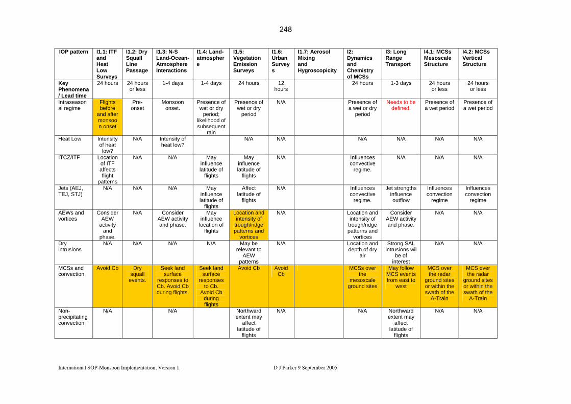
International SOP-Monsoon Implementation, Version 1. D J Parker 9 September 2005
IOP pattern I1.1: ITF and Heat Low Surveys
I1.2: Dry Squall Line Passage
I1.3: N-S Land-Ocean- Atmosphere Interactions
I1.4: Land-atmosphere
I1.5: Vegetation Emission Surveys
I1.6: Urban Surveys
Mixinand Hy
ynndh
SM aSt re
VS
I1.7: Aerosol g
groscopicity
I2DaCof
: amics
emistry MCSs
I3: Long Range Transport
I4.1: MCesoscructu
s le
I4.2: MCSs ertical tructure
Key Phenomena/ Lead time
24 hours 24 hours or less
1-4 days 1-4 days 24 hours 12 hours
2 urss or
4 hours 1-3 days 24 hoor le
s
24 hours less
Intraseasonal regime
Flights before
and after monsoon onset
Pre-onset
Monsoon onset.
Presence of wet or dry
period; likelihood of subsequent
rain
Presence of wet or dry
period
re w
P cea er a we
N/A Pa
sence ofet or dry
period
Needs to be defined.
resenwet p
of iod
Presence of t period
Heat Low Intensity of heat low?
N/A Intensity of heat low?
N/A N/A N/A N/A N/A N/A
ITCZ/ITF Location of ITF affects flight
patterns
N/A N/A May influence latitude of
flights
May influence latitude of
flights
Infco
r
N/A luencesnvective egime.
N/A N/A N/A
Jets (AEJ, TEJ, STJ)
N/A N/A N/A May influence latitude of
flights
Affect latitude of
flights
N/A Influenconve
regim e re
cesctive e.
Jet strengths influence outflow
Influences convection
regim
Influences convection
gime
AEWs and vortices
Consider AEW
activity and
phase.
N/A Consider AEW activity and phase.
May influence
location of flights
Location and intensity of
trough/ridge patterns and
vortices
N/A Locatiointensi
trough/pattern
vortic
n andty of ridge s and es
Consider AEW activity and phase.
N/A N/A
Dry intrusions
N/A N/A N/A N/A May be relevant to
AEW patterns
N/A Locatiodepth o
air
n andf dry Strong SAL
intrusions wil be of
interest
N/A N/A
MCSs and convection
Avoid Cb Dry squall
events.
Seek land surface
responses to Cb. Avoid Cb during flights.
Seek land surface
responses to Cb.
Avoid Cb during flights
Avoid Cb Avoid Cb
MCSs over the
mesoscale ground sites
May follow MCS events from east to
west
MCS over the radar
ground sites or n the withisw f the ath o
A-Train
MCS over the radar
ground sites or within the swath of the
A-Train
Non-precipitating convection
N/A N/A Northward extent may
affect latitude of
flights
N/A N/ A Northwardextent may
affect latitude of
flights
N/A N/A
248

International SOP-Monsoon Implementation, Version 1. D J Parker 9 September 2005
Land surface
Fli
andmon o
ghtsbefore
aftensonse
r ot
N/A Soil moisture will guide
flight planning
Strong E-W soil moisture
variability
N/A Rainfall ondry surface
could be attractive.
N/ Prob
A – nto b
clarif
ably eee ied
ds N/A N/A
Sp
perod
cial ucts
Sataer
prod
elliteosolucts
N/ .
A Soil moisture patterns
from satellite
Chemical trajectories.
Soil moisture patterns
from satellite
Soil moisture patterns
from satellite
Chemical trajectories
Ground ased rad
ductsb
pro ar
Gro
prod
und based radar
ucts
Tawhof IAls
Day
bleichOPo,
0
3. s.
da
1:hoOtta
0
Tauldherfro
1
bl be crm
e o taiter
the
0
f IOken
P forntoay aosc
4
ecast accoffect ale in
05 0
cruntthestr
6
ite fo du
07
riar ees
me
(toacirante
08
bh tbilid
e rypty site
09
efie of s,
neof Ian an
1
d aOP IOd
0
nd. P,fro
1
cTh orm
1
ooos thre
rdie se
cen
12
nathadett a
eddeailirc
1
wd ys ora
3
ithellf itft o
14
Aow
OC a
conserv
15
). re c
The elem this ta defi acto i ritical for cision ond that d
ia m s duct (e.g. e mings) mes b ations, will d in th ann proc .
0 02 3 0 16 18 20 21 2 23
ent thxacbe
17
s ine det tiuse
ble to c. e pl
19
ne fuct
ing
rs kin
ess
2
J-2 F stbriefing
Inter-AOC Discussio
n
TT8 meeti
oreca PI Group ng
J-1 Forecastbriefing
IOPlan
Gro
P ningup
NOTAM? PI Group Inter-AOC discussion
NOTAM? TT8 meeti
ng
J0 Range of morning take off
times
Forecastbriefing
Ra afternoo times nge of n take off
Table 3.2: 3.2 Planning A timetable for the jobs of this Task Team still needs to be developed.
need to be established. This task will be conducted by the Aircraft and Ground-based
Proposed decision-making schedule.
Personnel roles and availability during the SOP1-2 periods coordination groups, in a form similar to that shown in Table 3.3
249

International SOP-Monsoon Implementation, Version 1. D J Parker 9 September 2005
29/5 5/6 12/6 19/6 26/6 3/7 10/7 17/7 24/7 31/7 7/8 14/8 21/8 28/8 4/9 11/9 18/9 BAe146 Coe Heard Lewis McQuaid Monks Parker Reeves Stewart Taylor ATR42 F-F20 D-F20
Table 3.3: Template for the table of PIs during SOP1-3 (provisional) (Also compile for:
• SOP-Gourma • SOP-Niamey • SOP-Oueme • SOP-Dano • Other instruments ).
250

International SOP-Monsoon Implementation, Version 1. D J Parker 9 September 2005
5b). The logistics associated with aircraft will be coordinated by ST2 (which contains
ly
Niamey). We need to document: • operational requirements for each IOP pattern (Ix.y)
perational lead times for aircraft and for notification of ground tst requirements;
links with EOP logistics)
A site visit to each of the three mesoscale’ up, in clo e consult
.3.1 C munications
Apart from the communications needs for tcommunication during the SOP:
(a) Links between the AOC and the responsive of the IOPs.
an f data from radiila ri eathe
be mad a
elease of aircraft data to PIs for post-flight analysis, and planning of
3.3 Logistical considerations This TT will collect the logistical requirements of the ground-based instruments (see
several representatives of TT8).
We need to coordinate basic facilities in the centres of operational activity (notab
a. Air Traffic Control and restrictions; b. o
instrumen ; c. instrumen
• operational requirements for ground-based instruments (in particular,
• personnel requirements (city transit; accommodation etc).
sites must be coordinated by the ‘Ground-based sub-gro s ation with the AOC.
3 om
he AOC, the following are priorities for
instruments (Table 2.2b) for operation
(b) Tr smission o osondes and dropsondes to the GTS for assim tion into nume
e (Parker, Flamcal wnt) to info
r prediction (NWP) models. Particular efforts must rm NWP centres of this process and to ensure that
the dropsonde data is assimilated. ) Rapid r(c
subsequent flights.
251

4. Partnership 4.1 Field observations
toco rately-owned instruments is outlined in section 3 .
will be include operational discussions, as members of TT8.
op rger aircraft (BAe146, ATR42 …) to obtain artners to fly on IOP missions. This process requires considerable
anning and app e made ialaire Reeves or Cyrille Flamant. Information on this procedure will be sent to ST4.
ry effort the un p e PIAF in our operational ob
l co ill b to of
A decision-making proabove
l for sepa
4.2 Training program
All partners
d in the daily
Efforts will be made by erators of the lapermission for pforward pl lications should b immed tely to Doug Parker, C We will make eve to take account of funded rojects identified in th
jectives. 4.3 Collaboration The AMMA Internationaideas among members
nference in DakarTT8.
w e used exchange scientific
International SOP-Monsoon Implementation, Version 1. D J Parker 9 September 2005
252

5. Organisation of the TT
group, membership
Coordinators: oug Par
Core group: Crewell, Diedhiou, Flamant, Formenti, Hoeller, Kalthoff, Mari, Parker, Protat, Reeves, Thorncroft Representation: • All of WP4.2 (management) in the EU project • Instruments (a representative (PI) for each aircraft, and each ground instrument)
o D-F20 o F-F20 o ATR42 o BAe146 o Geophysica o Radar (Protat and Jenkins) o Aerosonde
• Science areas (selected EU work packages): o WP1.1 WAM/global climate (Fink, Law) o WP1.2 Water cycle (Roux) o WP1.3 Land-atmosphere (Parker) o WP1.4 Scaling issues (Hall) o WP2.1 Dynamics and convection (Parker) o WP2.2 Oceanic (Brandt) o WP2.3 Physical / biological processes over land (Kunstmann) o WP2.4 Aerosol/chemical processes (Mari, Formenti, Reeves) o WP3.1 Land productivity o WP3.2 Human processes o WP3.3 Water resources o WP3.4 Health (Morse) o WP4.1 Modelling (Lafore) o WP4.3 Satellite (Desbois) o WP4.4 Database (Eymard, Hoepffner) o WP5.1 Weather Prediction (Kamga, Beljaars)
• National and international groups: e.g. Benin, EU, France, Germany, Mali, Niger, UK, USA, CSAM (Diedhiou, Gaye), …
• The NASA funded N-Pol activity • AMMA-Weather • ARM / RADAGAST • International agencies: ACMAD, ASECNA, AGRHYMET, … • PIs of PIAF proposals • Representatives of linked TTs
o TT1 Radiosondes (Fink, Parker) o TT2 Fluxes (Taylor) o TT3 EOP meso Gourma o TT4 EOP meso Niamey o TT5 EOP meso Oueme
. 5.1 Leaders, core
Cyrille Flamant, D
ker
International SOP-Monsoon Implementation, Version 1. D J Parker 9 September 2005
253

o TT6 Ocean (Brand,TT7 SOP-0 (Coe)
Bourles) o o TT9 SOP-Downstream (Roux)
ns u) e
Training an ilding (Died r
usin ail and teleph e jor tional planning meeting, which has been proposed for 4-6 July 2005, to be
at the University of Le
al coordination
of the rvations will be coordinated within the existing part o . und-based
n ader aand Claire the leader of the ground-based group will be
TT to ensure that the operations of these plementary
or nd
sed by th nd d
lications will onsidered, and discussed with the ICIG where ecessary.
e also need to handle requests for new objectives with the old instruments! This ill be undertaken by the same groups.
External diffusion of the information and reporting
his TT will consist of members representing all the interest-groups relevant to SOP-onsoon. This TT will also include representatives of the ICIG, ISSC and CSAM.
ting information out of the TT.
o ST1 EOP o ST2 Operatioo ST3 Databas
Centres (Diedhio
o ST4 d capacity bu hiou, Pa ker)
We can conduct our binterna
ess by em one conf rence. We need a ma
held eds.
5.2 Intern
The implementation SOP obseEU project structure, with(part of WP4.2.2) coordi
separate Aircraft (ation groups. The le
f WP4.2s of the
1) and Groircraft group will be
Cyrille Flamant Susanne Crewell. It will be the work of this
Reeves;
groups are com .
5.3 How are requests f new instruments ha led?
These are discusFinancial imp
e whole TT8 group aalso be c
approve by the Core Group.
n Ww 5.4 TMThese individuals will be tasked with repor
International SOP-Monsoon Implementation, Version 1. D J Parker 9 September 2005
254
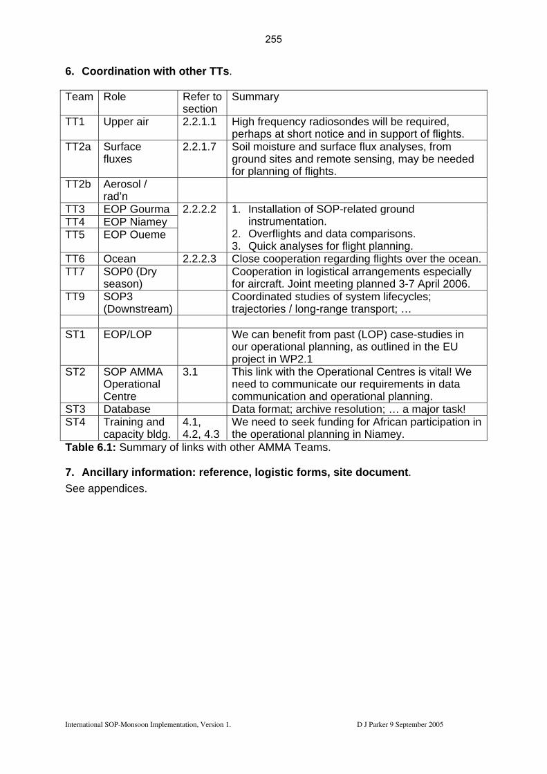
6. Coordination with other TTs. Team Role Re
sefer to Summary ction
TT1 Upper air 2.2.1.1 cy r dshor n .
High frequen adioson es will be required, perhaps at t notice a d in support of flights
TT2a Surface fluxes
2.2.1.7 Soil moisture and surfaceground sites and remote sensing, may be needed
g of fl
flux analyses, from
for plannin ights. TT2b Aerosol /
rad’n
TT3 EOP Gourma TT4 EOP Niamey TT5 EOP Oueme
2.2.2.2 1. Installation o -relmentat
s and data comparisons. lys flig
f SOP ated ground instru ion.
2. Overflight3. Quick ana es for ht planning.
TT6 Ocean 2. se cooperation regarding flights over the ocean.2.2.3 CloTT7 SOP0 (Dry
season) tion in l al a
int meeting Cooperafor
ogistic rrangements especially planned 3-7 April 2006. aircraft. Jo
TT9 SOP3 (Downstream)
tu f sy / long-range tr
Coordinated s dies o stem lifecycles; trajectories ansport; …
ST1 EOP/LOP We can benefit from past (LOP) case-studies in
tional ning, project in WP2.1 our opera plan as outlined in the EU
ST2 SOP AMMA Operational
tre
3. ith the tional Centres is vital! We mmunicate our
communication raCen
1 This link wneed to co
Opera requirements in data
and ope tional planning. ST3 Database Data format; archive resolution; … a major task! ST4 Training and
capacity bldg. 4.4.
ee g in l planning i ey.
1, We need to s2, 4.3 the operationa
k fundin for African participationn Niam
Table 6.1: Summary of lin ea 7. Ancillary information forms, site ent.
endices.
ks with other AMMA T ms.
: reference, logistic documSee app
International SOP-Monsoon Implementation, Version 1. D J Parker 9 September 2005
255

Appendix A1: F/F20 payload
Table A11 – MeasuremeBuck Research dew point
nts co s
Dew point SAFIRE @meteo.fr
mmon to all SOP
sensor M. Pontaud marc.pontaud
INS, GPS Position, winds, u,v,w SAFIRE @meteo.fr M. Pontaud marc.pontaud
5-port turbulence probe Turbulence SAFIRE M. Pontaud [email protected]
Rosemount Temperature T SAFIRE M. Pontaud [email protected]
Aerodata humidity sensor Relative Humidity SAFIRE M. Pontaud [email protected]
UV-O3 and IR-CO instrument O3 and CO in situ SAFIRE [email protected]
Stéphane Letourneur letourneu
Table A12 – Measurements re OP2-a1
ndes
quired for the SVertical profiles of dynamical variables AVAPS dropso SAFIRE M. Pontaud
Pygreometers and Pyranometers (Up/down)
ling/Downwelling, Broadband
UpwelVis/IRradiation
SAFIRE M. Pontaud [email protected] marc.ponta
Multichannel thermal infrared radiometer Brightness temperature SAFIRE [email protected]
M. Pontaud marc.po
Differential absorption lidar LEANDRE 2
2D water vapour field (vertical plane) IPSL C. Flamant
– Measurements re d for the SOP2-a2 Pygreometers and
/down)
Upwelling/Downwelling, Vis/IR Broadband radiation
SAFIRE M. Pontaud [email protected]
Table A13 quire
Pyranometers (Up
Photometer NO2 photolysis j(NO2) SAFIRE Mar Pontaud [email protected]
AVAPS dropsondes Vertical profiles of dynamical variables SAFIRE Mar Pontaud
Nitrogen oxides analyser NO, NO2 and NOy in situ LISA P. Perros [email protected]
Mircroadsorbent tubes and ground analysis with CG--MS
COV LISA P. Perros [email protected]
Oxygenated VOC sampling and ground analysis CG--MS Oxygenated COV LISA P. Perros
HCHO Formaldehyde LISA P. Perros [email protected]
H2O2 Hydrogen peroide LISA P. Perros [email protected]
HNO3 Nitric acid par MONA LISA P. Perros [email protected]
PAN Peroxyacetylnitrate LISA P. Perros [email protected]
Table A14 – Measurements required for the SOP2-a3
International SOP-Monsoon Implementation, Version 1. D J Parker 9 September 2005
256

RALI Cloud optical properties and microphisics
DT/INSU IPSL
N. Grand [email protected]
Size particle/rain drop distribution
PCSAP – 2 DC - 2 DP - FSSP SAFIRE M. Pontaud
AVAPS dropsondes Vertical profiles of dynamical variables SAFIRE Mar Pontaud
International SOP-Monsoon Implementation, Version 1. D J Parker 9 September 2005
257
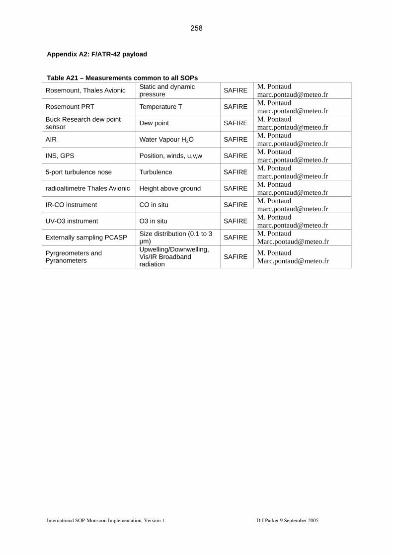
Appendix A2: F/ATR-42 payload
Table A21 – Measurements common to all SOPs
Rosemount, Thales Avionic Static and dynamic pressure SAFIRE M. Pontaud
Rosemount PRT Temperature T SAFIRE M. Pontaud [email protected]
Buck Research dew point sensor Dew point SAFIRE M. Pontaud
AIR Water Vapour H2O SAFIRE M. Pontaud [email protected]
INS, GPS Position, winds, u,v,w SAFIRE M. Pontaud [email protected]
5-port turbulence nose Turbulence SAFIRE M. Pontaud [email protected]
radioaltimetre Thales Avionic Height above ground SAFIRE M. Pontaud [email protected]
IR-CO instrument CO in situ SAFIRE M. Pontaud [email protected]
UV-O3 instrument O3 in situ SAFIRE M. Pontaud [email protected]
Externally sampling PCASP Size distribution (0.1 to 3 µm) SAFIRE M. Pontaud
[email protected] Pyrgreometers and Pyranometers
Upwelling/Downwelling, Vis/IR Broadband radiation
SAFIRE M. Pontaud [email protected]
International SOP-Monsoon Implementation, Version 1. D J Parker 9 September 2005
258

Table A22 – Measurements required for the SOP2-a1
Gerber Probe, King Probe Liquid water content SAFIRE M. Pontaud [email protected]
Chimiluminescence NOx instrument (METAIR) NO, NO2 in situ SAFIRE M. Pontaud
Photometer NO2 photolysis j(NO2) SAFIRE M. Pontaud [email protected]
Size particle / rain drop distribution FSSP SAFIRE M. Pontaud
[email protected] AVIRAD particle inlet Coarse particle inlet
(AVIRAD)° LISA/LSCE [email protected]
Optical sizer GRIMM Size distribution (0.3-20 um) LISA [email protected]
7-λ aethalometer Particle soot, black carbon LISA [email protected]
3-λ Nephelometer Spectral Scattering and backscattering coefficients
LISA [email protected]
filters for individual particle analysis
Particle shape and composition LISA [email protected]
4-stage impactors Aerosol composition and mass distribution LISA [email protected]
Particle inlet Aerosol Particle inlet ("Veine communautaire") CNRM L. Gomes
[email protected] filters for sub and supermicron particle collection
Ions, trace, BC/OC LA V. Pont [email protected]
Ultrafine CPC Particle number concentration > 3nm CNRM L. Gomes
CCN counter CCN CNRM L. Gomes [email protected]
Multi-channel CPCs Size distribution > 10nm CNRM L. Gomes [email protected]
DMPS Size distribution of Aitken and accumulation mode particles (20-1000 nm)
LaMP P. Lal [email protected]
PCASPX Size distribution 0.3-10 µm LaMP
P. Lal [email protected]
Thermodenuder Volatility analysis of particles LaMP
P. Lal [email protected]
X-Probe Aerosol and droplet size distribution (0.5-50 µm) CNRM L. Gomes
Fast FSSP Cloud droplet spectrum CNRM L. Gomes [email protected]
International SOP-Monsoon Implementation, Version 1. D J Parker 9 September 2005
259

Table A23 – Measurements required for the SOP2-a2
Gerber Probe, King Probe Liquid water content SAFIRE M. Pontaud [email protected]
Chimiluminescence NOx instrument (METAIR) NO, NO2 in situ SAFIRE M. Pontaud
Photometer NO2 photolysis j(NO2) SAFIRE M. Pontaud [email protected]
Size particle / rain drop distribution FSSP SAFIRE M. Pontaud
Spectres dimensionnels LaMP Alfons Schwarzenboeck [email protected]
Particle inlet Aerosol Particle inlet ("Veine communautaire") CNRM L. Gomes
[email protected] filters for sub and supermicron particle collection
Ions, trace, BC/OC LA V. Pont [email protected]
Ultrafine CPC Particle number concentration > 3nm CNRM L. Gomes
CCN counter CCN CNRM L. Gomes [email protected]
Multi-channel CPCs Size distribution > 10nm CNRM L. Gomes [email protected]
DMPS Size distribution of Aitken and accumulation mode particles (20-1000 nm)
LaMP P. Lal [email protected]
PCASPX Size distribution 0.3-10 µm LaMP
P. Lal [email protected]
Thermodenuder Volatility analysis of particles LaMP
P. Lal [email protected]
X-Probe Aerosol and droplet size distribution (0.5-50 µm) CNRM L. Gomes
Fast FSSP Cloud droplet spectrum CNRM L. Gomes [email protected]
Microadsorbent tubes and ground analysis with GC--MS COV LISA P. Perros
[email protected] Oxygenated VOC sampling and ground analysis with GC--MS
Oxygenated COV LISA P. Perros [email protected]
Peroxyde Fluorometer Speciated peroxides LISA P. Perros [email protected]
PAN-GC Peroxyactylnitrate LISA P. Perros [email protected]
HNO3 Nitric acid LISA P. Perros [email protected]
International SOP-Monsoon Implementation, Version 1. D J Parker 9 September 2005
260
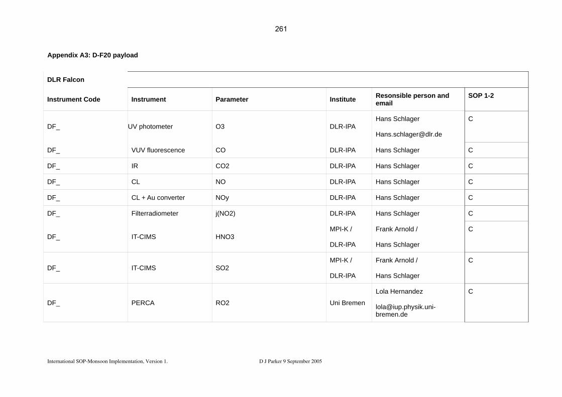
International SOP-Monsoon Implementation, Version 1. D J Parker 9 September 2005
Appendix A3: D-F20 payload
DLR Falcon
Instrument Code
DF_ UV
DF_
DF_
DF_ CL
DF_
DF_ Filterradiometer
DF_ IT
DF_ IT
DF_ PERCA
Instrument Parameter Institute Resonsible person and email
SOP 1-2
photometer O3 DLR-IPA Hans Schlager
C
VUV fluorescence CO DLR-IPA Hans Schlager C
IR CO2 DLR-IPA Hans Schlager C
NO DLR-IPA Hans Schlager C
CL + Au converter NOy DLR-IPA Hans Schlager C
j(NO2) DLR-IPA Hans Schlager C
-CIMS HNO3 MPI-K /
DLR-IPA
Frank Arnold /
Hans Schlager
C
-CIMS SO2 MPI-K /
DLR-IPA
Frank Arnold /
Hans Schlager
C
RO2 Uni Bremen
Lola Hernandez
C
261

International SOP-Monsoon Implementation, Version 1. D J Parker 9 September 2005
DF_ CPSA (Multi-channel condensation particle counter)
Nucleation mode aerosol size distribution DLR-IPA
Andreas Minikin
C
DF_ Airborne-DMA
DF_ PCASP-100X
DF_ FSSP-300,
DF_
DF_
DF_
DF_
DF_
DF_
DF_
Aitken mode aerosol size distribution DLR-IPA Andreas Minikin C
Accuumulation mode aerosol size distribution DLR-IPA Andreas Minikin C
FSSP-100 Coarse mode aerosol and cloud element size distribution DLR-IPA Andreas Minikin C
Thermodenuder + condensation particle counters
Aitken mode aerosol : volatile and non-volatile particle fractions DLR.IPA Andreas Minikin
C
PSAP absorption photometer Aerosol absorption coefficient DLR-IPA Andreas Minikin C
Impactor sampler Single particle analysis DLR-IPA Andreas Minikin C
Rosemount temp probes temperature DLR-FB Andreas Giez
B2, C
INS, GPS Position, wind DLR-FB Andreas Giez B2, C
Lyman-alpha Relative humidity DLR-FB Andreas Giez B2, C
WIND lidar Wind field DLR-IPA Oliver Reitebuch
B2
262

Appendix A4: UK-BAe146 payload
UK BAe-146
Instrument Code Instrument Parameter Institute Resonsible person and email
SOP 1-2
BAE146_RTMP • Rosemount Thermometers
Non-deiced/deiced temperatures FAAM Stephen Devereau [email protected]
C
BAE146_GEDP • General eastern Dew point FAAM Stephen Devereau [email protected]
C
BAE146_FWVS • FWVS Lyman-α fluorescence
Water vapour UKMO Jim Haywwod [email protected]
C
BAE146_INGPS • INS, GPS, wind vanes
Position, winds, u,v,w FAAM Stephen Devereau [email protected]
C
BAE146_CGPS • Cruciform GPS Position UFAM/Camb Stephen Devereau [email protected]
C
BAE146_VID • Video cameras Forward, rearward, upward, downward
FAAM Stephen Devereau [email protected]
C
BAE146_RALT • Radar altimeter Altitude FAAM Stephen Devereau [email protected]
C
BAE146_RAD • Radar Rainfall UFAM/Camb Stephen Devereau [email protected]
C
BAE146_5PTP • 5-port turbulence probe
Turbulence UFAM/Camb Stephen Devereau [email protected]
C
International SOP-Monsoon Implementation, Version 1. D J Parker 9 September 2005
263

BAE146_HIRT • Heimann IR thermometer
SST FAAM Stephen Devereau [email protected]
C
BAE146_SWS • SWS Short wave radiation UKMO Jim Haywwod
C
BAE146_DROPS AVAPS dropsondes Vertical profiles of dynamical variables
FAAM Stephen Devereau [email protected]
C
BAE146_BBR Pygreometers and Pyranometers
Broadband radiation FAAM Stephen Devereau [email protected]
C
BAE146_JNO2 Photometer NO2 photolysis j(NO2) Leicester Paul Monks [email protected]
C
BAE146_JO1D Fixed bandwidth radiometry,
O3 photolysis j(O1D) Leicester Paul Monks [email protected]
C
BAE146_O3 • UV Ozone in situ FAAM Stephen Devereau [email protected]
C
BAE146_CO VUV fluorescence Carbon monoxide CO FAAM Stephen Devereau [email protected]
C
BAE146_PTRMS PTR-MS Real-time Oxygenates UEA David Oram [email protected]
C
BAE146_WDCGC Whole air samples (WAS) and ground analysis with dual channel GC
>100 VOCs inc NMHCs, alcohols, ketones, aldehydes, ethers
York Ally Lewis [email protected]
C
BAE146_W2DGC WAS and ground analysis with 2DGC
Semivolatile VOCs York Ally Lewis [email protected]
C
BAE146_TGCTMS Microadsorbent tubes and ground analysis with GC-TOF-MS
VOCs York Ally Lewis [email protected]
C
International SOP-Monsoon Implementation, Version 1. D J Parker 9 September 2005
264

BAE146_WGCMS WAS and ground analysis with GC-MS
>40 halocarbons UEA David Oram [email protected]
C
BAE146_NOXY Gold convertor + chemiluminescence
NOY, NO, NO2, HNO3 UEA David Stewart [email protected]
C
BAE146_TECNOX TECO NOX FAAM Stephen Devereau [email protected]
C
BAE146_PAN Gas chromatography (GC)
Peroxyacetylnitrate UFAM/York Jim Hopkins [email protected]
C
BAE146_H2O2 Fluorometric Speciated peroxides (inorg/organic)
UEA Brian Bandy [email protected]
C
BAE146_HCHO Fluorometric Formaldehyde UEA Graham Mills [email protected]
C
BAE146_PERCA Chemical amplifier – PERCA
Peroxy radicals (RO2 + HO2) Leicester/UEA
Paul Monks [email protected]
C
BAE146_FAGE FAGE (laser induced fluorescence at low pressure)
OH, HO2 Leeds/UFAM Dwayne Heard [email protected]
C
BAE146_AMS Aerosol mass spectrometer AMS
Aerosol size and composition UNIMAN/
UFAM
Hugh Coe [email protected]
C
BAE146_CPC TSI condensation particle counters
Particle number concentration > 3nm
FAAM/ UNIMAN
Hugh Coe [email protected]
C
BAE146_PCASP internally and externally sampling (OPCs) PCASP
Size distribution (0.2-30 um) FAAM Stephen Devereau [email protected]
C
International SOP-Monsoon Implementation, Version 1. D J Parker 9 September 2005
265
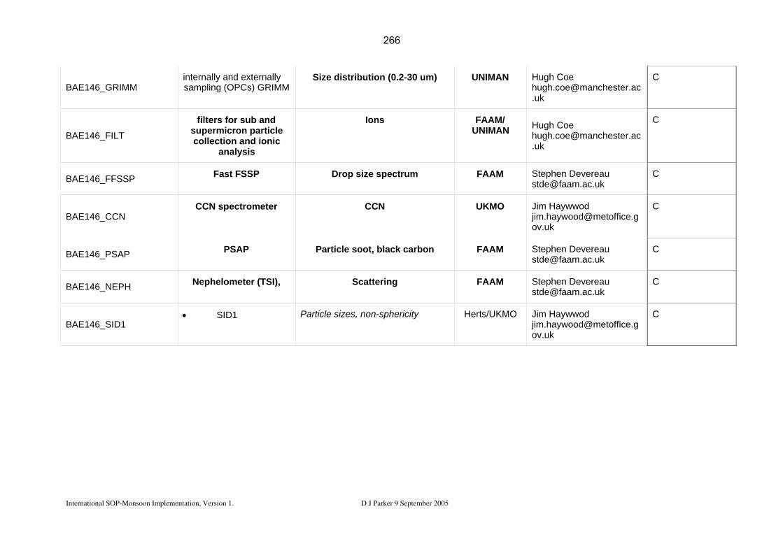
BAE146_GRIMM internally and externally sampling (OPCs) GRIMM
Size distribution (0.2-30 um) UNIMAN Hugh Coe [email protected]
C
BAE146_FILT
filters for sub and supermicron particle collection and ionic
analysis
Ions FAAM/ UNIMAN Hugh Coe
C
BAE146_FFSSP Fast FSSP Drop size spectrum FAAM Stephen Devereau [email protected]
C
BAE146_CCN CCN spectrometer CCN UKMO Jim Haywwod
C
BAE146_PSAP PSAP Particle soot, black carbon FAAM Stephen Devereau [email protected]
C
BAE146_NEPH Nephelometer (TSI), Scattering FAAM Stephen Devereau [email protected]
C
BAE146_SID1 • SID1 Particle sizes, non-sphericity Herts/UKMO Jim Haywwod
C
International SOP-Monsoon Implementation, Version 1. D J Parker 9 September 2005
266

Appendix A5: Geophysica payload
Geophysica
Instrument Code Instrument Parameter Institute Resonsible person and email
SOP 1-2
GEO_O3FOZAN FOZAN Dye chemiluminescensce + ECC
O3 CNR Fabrizio Ravegnani
C
GEO_O3FOX FOX UV absorption O3 DLR Hans Schlager
C
GEO_H2OFISH FISH Lyman-� photo-fragment flourescence
H2O
(total)
FZJ Cornelius Schiller
C
GEO_H2OFLASH FLASH Lyman-�
H2O
(gas phase)
CAO Vladimir Yushkov
C
GEO_ACH ACH mirror hygrometer with digital feedback
H2O frost-point -> H2O (gas phase) CAO Vladimir Yushkov
C
GEO_SIOUXNOY
SIOUX Chemi-luminescence,
+ Au-converter
+ Subisokinetic inlet
NO
NOy
Particle NOy
DLR Hans Schlager
C
International SOP-Monsoon Implementation, Version 1. D J Parker 9 September 2005
267

International SOP-Monsoon Implementation, Version 1. D J Parker 9 September 2005
GEO_HALOX
HALOX Chemical-conversion resonance fluorescence
+ thermal dissociation
ClO
BrO,
ClONO B2B
FZJ Fred Stroh
C
GEO_HAGAR
HAGAR GC/ECD
GC/ECD
GC/ECD
GC/ECD
GC/ECD
IR absorption
N B2BO, CFC 12, CFC11
Halon 1211
SFB6
CH B4
CO
CO B2B
Uni Frankfurt C. Michael Volk
C
GEO_TDL ALTO TDL
N B2BO,
CH B4
CO
INOA Piero Mazzinghi
C
GEO_COTDL CO-TDL INOA Piero Mazzinghi
C
GEO_COPASCN
COPAS 4 channels
2-channel CN counter,
one inlet heated
Condensation nuclei (CN-total , CN-non-volatile)
Uni Mainz Stephan Borrmann
C
268

International SOP-Monsoon Implementation, Version 1. D J Parker 9 September 2005
GEO_FSSP FSSP3000 or FSSP100
Laser-particle pectrometer
Size speciated aerosols (0.4-40µm) Uni Mainz Stephan Borrmann
C
GEO_PIMAG Particle Imager Uni Mainz Stephan Borrmann
C
GEO_MAS MAS Multi-wavelength
Scattering
Aerosol optical properties CNR Francesco Cairo
C
GEO_MAL MAL 1 &2 Microjoule-lidar
Remote Aerosol Profile (2km from aircraft altitude)
Obs. Neuchatel
Valentin Mitev
C
GEO_WASISO WAS Whole air sampler Trace gas isotopes
Water vapour isotopes
MPI-Heidelberg
Thomas Röckmann
C
GEO_RTMP TDC Rosemount probe Temperature CAO G. Shur
C
GEO_5PTP PT100, 5-hole probe horizontal wind CAO G. Shur
C
GEO_MTP MTP Microwave passive sensor
vertical profile of temperature and potential temperature
JPL MJ Mahoney
C
GEO_SMOKE SMOKE
Vertical velocity
Diffusivity
AWI Markus Rex
C
269

International SOP-Monsoon Implementation, Version 1. D J Parker 9 September 2005
Appendix GG: Ground-based instrumentation
Instrument Period Code Instit’n PI Location Deployment Period Mode Sampling Oceanic instrumented mast SOP OS.Mat_SAG_E CNRM Caniaux Atalante/EGGE M Flux station SOP AS.Flux_D FZK Kalthoff Dano 1 June - end July M 30 min Radiosounding Dano SOP AS.Rs_D FZK Kalthoff Dano 1 June - end July R 3-6 hrs Radiosoundings Network
EOP-SOP TT1 EOP R
Driftsondes SOP AS.Drift_T1_E CNES/NCAR Drobinski / Parsons N'Djamena 15 Aug.-30 Sep. R
Constant volume balloon SOP AS.BVC_T2_E CNES Drobinski Cotonou/Djo? 15 June - 15 July R Oceanic soundings SOP OS.RS_SAG_E CNRM Caniaux Atalante/EGGE R
Ozone soundings EOP-SOP AS.RSO3_Od_E LA Thouret Cotonou June-August M
Lidar SOP AS.TRESS_Tam_E IPSL Flamant Tamanrasset all SOPs M Lidar SOP AS.lidar_Mbour LOA Tanré M'Bour Lidar Ceilometer CT25K SOP AE.CT25K U Bonn Crewell Djougou Jan-Dec 2006 M 15 sec Micropulse lidar (MPL) SOP Reading Slingo Niamey Jan-Dec 2006 M Wet and dry deposition fluxes, etc.. SOP AS.Dust.ST_flux UP12 Rajot Niamey all SOPs M Aerosol characteristion SOP UP12 Desboeufs Niamey SOP 1-2 M
continuous
Chemical instrumentation SOP AS.DUST_Od UPS Pont Djougou SOP2-a1 M
X-Band pol. Radar EOP-SOP AS_RADX_O IRD Gosset Djougou EOP R
C-Band Radar Ronsard SOP AS.Ronsard_O_E CNRS Scialom Djougou 15 Jun-15 Sep R Micro Rain Radar SOP AE_RADK_T U Bonn Crewell Djougou Jan-Dez 2006 M 10 sec Bistat. Radar (Wind field) SOP
AS_BIST.RADAR_O DLR Hagen Djougou 15 Jun-15 Sep M Continuous
Lightning detection network SOP DLR Höller Djougou SOP1-2 M Continuous
270

International SOP-Monsoon Implementation, Version 1. D J Parker 9 September 2005
Sodar network SOP AE.SODAR_ U Leeds Kalthoff / Parker Niamey 1 June - 21 Aug M
Microwave Radiometer SOP AE.PROF_T U Bonn Crewell Djougou Jan-Dec 2006 M 1 min GPS humidity SOP AS.GPS_1 CNRS Bock Timbuktu May-Sept 2006 M 30 min. GPS humidity SOP AS.GPS_2 CNRS Bock Ouagadougou May-Sept 2006 M GPS humidity SOP AS.GPS_3 CNRS Bock Tamale May-Sept 2006 M
Tethered balloon SOP U Leeds Parker Niamey 15 July - 21 Aug R to be arranged
Marisonde buoys OS.Mari_SAG_E CNRM Rolland Gulf of Guinea M Seabird SBE-19 and XTBs OS.ITAF_Sn_E LEGOS Bourles Tropical Atlantic July-September Expendable probes OS.XBT_GG_E LEGOS Bourles Gulf of Guinea
ARM Mobile facility SOP Slingo Niamey Jan-Dec 2006 M
271