the international pharmacopoela -...
TRANSCRIPT

THE INTERNATIONAL PHARMACOPOELA
THIRD EDITION
VOLUME 1
GENERAL METHODS OF ANALYSIS

THE INTERNATIONAL PHARMACOPOEIA
THIRD EDITION
PHARMACOPOEA INTERNATIONALIS EDIT10 TERTIA
Volume 1
General Methods of Analysis
WORLD HEALTH ORGANIZATION
GENEVA 1979

ISBN 92 4 154150 4
0 World Health Organization 1979
Publications of the World Health Organization enjoy copyright protection in accordance with the provisions of Protocol 2 of the Universal Copyright Convention. For rights of reproduction or translation of WHO publications, in part or in toto, application should be made to the Office of Publications, World Health Organization, Geneva, Switzerland. The World Health Organization welcomes such applications.
The designations employed and the presentation of the material in this publication do not imply the expression of any opinion whatsoever on the part of the Secretariat of the World Health Organization concerning the legal status of any country, territory, city or area or of its authorities, or concerning the delimitation of its frontiers or boundaries.
The mention of specific companies or of certain manufacturers' products does not imply that they are endorsed or recommended by the World Health Organization in preference to others of a similar nature that are not mentioned. Errors and omissions excepted, the names of proprietary products are distinguished by initial capital letters.
PRINTED IN FRANCE
7813944 - 9000 - BERGER-LEVRAULT

CONTENTS Page
. . . . . . . . . . . . . . . . . . . . . . . . . . Preface . . . . . . . . . . . . . . . . . . . . . . General notices
. . . . . . . . . . . . . . . . . . . . Units of measurement
PHYSICAL METHODS
. . . . . . . . . . . . . . . . . . . . Measurement of mass Determination of melting temperature. melting range. congealing
. . . . . . . . . . . point. boiling point. and boiling range Determination of mass density and relative density . . . . . . . Determination of optical rotation and specific rotation . . . . .
. . . . . . . . . . . . . . Determination of refractive index Spectrophotometry in the visible and ultraviolet regions . . . .
. . . . . . . . . . . Spectrophotometry in the infrared region . . . . . . . . . . . . Atomic absorption spectrophotometry
. . . . . . . . . . . . . . . Fluorescence spectrophotometry
. . . . . . . . . . . . . . . Turbidimetry and nephelometry . . . . . . . . . . . . . . . . . . . . . . Colour of liquids
. . . . . . . . . . . . . . . . . . . . Radiopharmaceuticals . . . . . . . . . . . . . . . . . Powder fineness and sieves
PHYSICOCHEMICAL METHODS
. . . . . . . . . . . . . . . . . . . . . Chromatography 79 Determination of pH . . . . . . . . . . . . . . . . . . . . 95
. . . . . . . . . . . . . . . . . . . . . . Electrophoresis 98 . . . . . . . . . . . . . . . . . . . Phase solubility analysis 102
CHEMICAL METHODS
. . . . . . . . . . . . . . . . . General identification tests 111 . . . . . . . . . . . . . . . . . . . Limit test for chlorides 115
. . . . . . . . . . . . . . . . . . . . Limit test for sulfates 116 . . . . . . . . . . . . . . . . . Limit test for heavy metals 117
. . . . . . . . . . . . . . . . . . . . . Limit test for iron 120 . . . . . . . . . . . . . . . . . . . . Limit test for arsenic 121
. . . . . . . . . . . . . . . . . . . . . . . . Sulfated ash 123 . . . . . . . . . . . . . . . . . . . . Oxygen flask method 123

6 CONTENTS
Page
. . . . . . . . . . . . . . . . . Complexometric titrations 126 . . . . . . . . . . . . . . . . . . . Non-aqueous titration 129
. . . . . . . . . . . . . . . . . . . . . . Nitrite titration 133 . . . . . . . Determination of water by the Karl Fischer method 134
. . . . . . . . . . . . . . . . . Determination of methoxyl 135
. . . . . . . . . . . . . . . . . Determination of nitrogen 136 . . . . . . . . . . . . . . . . Determination of iodine value 137
. . . . . . . . . . . Determination of peroxides in fixed oils 138 . . . . . . . . . . . . . Determination of saponification value 139
. . . . . . . . . . . . Determination of unsaponifiable matter 139 . . . . . . . . . . . . . . . . . Determination of acid value 140
BIOLOGICAL METHODS
. . . . . . . . . . . . . . Microbiological assay of antibiotics 145 . . . . . . . . . . . . . . . . . Sterility testing of antibiotics 151
. . . . . . . . . . . . . . . . . . . . . . Undue toxicity 154 . . . . . . . . . . . . . . . . . . . . . Test for pyrogens 155
Test for histamine-like substances (vasodepressor substances) . . . 156
. . . . . . . . . . . Determination of ash and acid-insoluble ash 161
. . . . . . . . . . lnternational chemical reference substances 165 . . . . . Names. symbols. and relative atomic masses of elements 166 . . . . . List of reagents. test solutions. and volumetric solutions 167
. . . . . . . . . . . . . . . . . . . . . . . . . . . Index 215

PREFACE
The International Pharmacopoeia is published by the World Health Organization by virtue of resolution WHA3.10' of the Third World Health Assembly. The first edition was published in two volumes, the first in 1951 and the second in 1955, followed by a Supplement in 1959; all of these were issued in English, French and Spanish. German and Japanese translations have also been published. The second edition was published in 1967, followed by a Supplement in 1971. These were issued in English, French, Russian and Spanish.
The WHO Expert Committee on Specifications for Pharmaceutical Preparations, in its 25th and 26th reports, has reviewed the organization of work on the revision of the International Pharmacopoeia and on the production and review of quality specifications published by the World Health Qrganization. It recommended suitable procedures and estab- lished priorities with a view to the implementation of World Health Assembly resolutions WHA20.34,2 which requested the Director-General "to continue work on analytical control specifications", and WHA28.66,3 which requested the Director-General "to continue to develop activities related to the establishment and revision of international standards, requirements and guidelines for prophylactic and therapeutic substances".
Following these recommendations, work has been proceeding on the preparation of the third edition of the International Pharmacopoeia, which will be published in several volumes. Volume 1 contains the descrip- tion of general methods of analysis; it will be followed by volumes containing the monographs, i.e., quality specifications for individual drugs, primarily for those most widely used in general health care.
The selection of the methods and procedures included in volume 1 of the third edition was based on their utility for the purpose of assuring the quality of pharmaceuticals. Numerous alterations have been made in the methods retained from previous editions to bring them into line with progress in the development of new analytical tools. Full account was, however, taken of various technical and economic constraints, and in the choice of recommended procedures optimum solutions were sought that will, it is hoped, permit their use by drug quality control laboratories located in developing countries as well.
WHO Handbook of Resolutions and Decisions, vol. 1 , 1973, p. 127. WHO Handbook of Resolutions and Decisions, vol. I , 1973, p. 132. WHO Handbook of Resolutions and Decisions, vol. 11, third edition, 1979, p. 52.

8 INTERNATIONAL PHARMACOPOEIA
The revision of the general methods of analysis included in Volume 1 of the third edition was carried out with the help of the members of the WHO Expert Advisory Panel on the International Pharmacopoeia and Pharmaceutical Preparations and other specialists. The process of revision was carried out in a series of meetings held during the period 1974-1977 and by correspondence. In July 1978 the draft text of volume I of the third edition of the International Pharmacopoeia was sent for final com- ments to all WHO Member States, to members of the WHO Expert Advisory Panel on the International Pharmacopoeia and Pharmaceutical Preparations, and to other specialists.
The following specialists participated both in person and by corres- pondence in the above-mentioned discussions, and commented on the final draft: Professor E.A. Babayan, Ministry of Health, Moscow, USSR; Dr D. Banes, The United States Pharmacopoeia, Rockville, MD, USA; Dr. I. Bayer, National Institute of Pharmacy, Budapest, Hungary; Dr T. BiCan, Institute for the Control of Drugs, Zagreb, Yugoslavia; Mr J.Y. Binka, Government Chemical Laboratory, Accra, Ghana; Professor W.H. Briner, Duke University Medical Center, Durham, NC, USA; Mr J.R. Burianek, State Institute for the Control of Drugs, Prague, Czechoslovakia; Dr T. Canback, Swedish Pharmacopoeia Commission, Stockholm, Sweden; Dr J.C. Charlton, The Radio- chemical Centre, Amersham, England; Professor Y. Cohen, Atomic Energy Commission, Saclay, Gif-sur-Yvette, France; Dr D. Cook, Drug Research Laboratories, Ottawa, Ontario, Canada; Dr N. Diding, WHO Collaborating Centre for Chemical Reference Substances, Solna, Sweden; Dr L.F. Dodson, National Biological Standards Laboratory, Department of Health, Canberra, Australia; Dr K. Florey, The Squibb Institute for Medical Research, New Brunswick, NJ, USA; MS M.A. Garth, National Center for Antibiotics Analysis, Food and Drug Administration, Washing- ton, DC, USA; Dr A.R. Gennaro, The Philadelphia College of Phar- macy and Science, Philadelphia, PA, USA; Dr T. George, Ciba-Geigy Research Centre, Goregaon, Bombay, India; Mr W. Hewitt, Cheltenham, England; Mr Kang Hu, Peking Institute for the Control of Pharma- ceutical and Biological Products, Peking, People's Republic of China; Dr T. Inoue, National Institute of Hygienic Sciences, Tokyo, Japan; Miss S. Johansson, WHO Collaborating Centre for Chemical Reference Substances, Solna, Sweden; Mr C.A. Johnson, British Pharmacopoeia Commission, London, England; Mr H.G. Kristensen, The Danish Pharmacopoeia Council, Brsnshsj, Denmark; Dr K. Kristensen, The Isotope Pharmacy, Brsnshsj, Denmark; Dr C.S. Kumkumian, Bureau of Drugs, Food and Drug Administration, Rockville, MD, USA; Dr E. Lang, Ciba-Geigy SA, Basle, Switzerland; Professor J. Laszlovszky, National Institute of Pharmacy, Budapest, Hungary; Dr T. Layloff, National Center for Drug Analysis, Food and Drug Administration, St Louis,

PREFACE 9
MO, USA; Dr J.W. Lightbown, National Institute for Biological Stan- dards and Control, London, England; Dr A.J. Liston, Drugs Directorate, Ottawa, Ontario, Canada; Mr W.J. Mader, Glza Corporation, Palo Alto, CA, USA; Professor M.D. MaSkovskij, Pharmacopoeia Committee of the USSR, Moscow, USSR; Dr E. Nieminen, Laakelaboratorio, Helsinki, Finland; Dr A.N. Obojmakova, Pharmacopoeia Committee of the USSR, Moscow, USSR; Mr B. ohrner, WHO Collaborating Centre for Chemical Reference Substances, Solna, Sweden; Dr T. Olawuyi Oke, Federal Drug Quality Control Laboratory, Yaba, Lagos State, Nigeria; Professor X. Perlia, Institut de Pharmacie, Zurich, Switzerland; Dr M. Pesez, Roussel Uclaf SA, Romainville, France; Professor J. Richter, Institut fiir Arzneimittelwesen der DDR, Berlin-Weissensee, German Democratic Republic; Dr G. Schwartzman, Bureau of Drugs, Food and Drug Administration, Washington, DC, USA; Professor S.D. Sokolov, All-Union Chemico-Pharmaceutical Research Institute, Moscow, USSR; Dr I. Suzuki, National Institute of Hygienic Sciences, Tokyo, Japan; Mr Tien Sung-chiu, Peking Institute for the Control of Pharmaceutical and Biological Products, Peking, People's Republic of China; Mr Tu Kuo-shih, Peking Institute for the Control of Phamaceutical and Biolo- gical Products, Peking, People's Republic of China; Dr M.M. Tuckerman, School of Pharmacy, Temple University, Philadelphia, PA, USA; Pro- fessor H. Vanderhaeghe, Rega Pharmaceutical Institute, Leuven, Bel- gium; Dr R. Vasiliev, State Institute for Drug Control and Pharmaceutical Research, Bucharest, Romania; Dr A. VCgh, Hungarian Pharmacopoeia Commission, Budapest, Hungary; Mr W.J. Welsh, Radiation Medicine Division, Ottawa, Ontario, Canada; Dr B.A. Wills, Allen & Hanburys Ltd., Ware, England; Dr W.W. Wright, Bureau of Drugs, Food and Drug Administration, Washington, DC, USA.
Furthermore, comments were obtained from the International Atomic Energy Agency, the Austrian Pharmacopoeia Commission, the Danish Pharmacopoeia Council, the French National Pharmacopoeia Com- mission, the Pharmacopoeia Commission of the Federal Republic of Germany, the Hungarian Pharmacopoeia Commission, and the United States Pharmacopoeia; from the Ministries of Health of Bulgaria, Romania and Sweden; and also from the National Biological Standards Laboratory, Canberra, Australia, the Drug Research Laboratories, Ottawa, Ontario, Canada, and the Department of Scientific and Industrial Research, Wellington, New Zealand. In addition, some professional associations provided comments and suggestions.
The World Health Organization takes this opportunity to express its gratitude to all those persons and institutions who took part in the preparation of this volume.
Mr C.A. Johnson served as Chairman at the above-mentioned meetings of the WHO Expert Committee on Specifications for Pharmaceutical

10 INTERNATIONAL PHARMACOPOEIA
Preparations. The functions of Secretary to the Committee were assumed by Mr 0. WallCn, Chief Pharmaceutical Officer, WHO, and by Dr W. Wie- niawski, Senior Pharmaceutical Officer, assisted by Miss M. Schmid, Technical Assistant.
Volume 1 of the third edition of the International Pharmacopoeia contains the description of 42 general methods of analysis. For mast of the physical and physicochemical methods an introductory description is given followed by recommended procedures. This general description is designed to facilitate the utilization of these methods for the purpose of drug quality assurance, even outside the scope of specifications pub- lished in the International Pharmacopoeia.
In accordance with resolution WHA30.39' of the Thirtieth World Health Assembly the units of measurement used in the third edition of the International Pharmacopoeia are based on the International System of Units (SI) (see page 13).
The general notices that precede volume I of the third edition concern primarily terms and provisions applicable in connexion with the general methods of analysis and will be expanded in subsequent volumes.
In accordance with World Health Assembly resolution WHA3.10 mentioned above, the International Pharmacopoeia constitutes a col- lection of recommended methods and specifications that are not intended to have a legal status as such in any country, unless expressly introduced for that purpose by appropriate legislation, but are offered to serve as references so that national requirements can be established on a similar basis in any country. Any Member State of the World Health Organ- ization may include all or part of these provisions in its national require- ments.
All comments and suggestions concerning the contents of the Inter- national Pharmacopoeia will be examined, and suggested amendments considered for inclusion in subsequent volumes of the International Pharmacopoeia.
GENERAL NOTICES
Quantities and their precision
The quantities of substances and reagents to be used in the tests, assays, and procedures have to be measured with adequate precision. The required precision is indicated by the number of decimals given in the text. For example, 20 indicates a value not less than 19.5 and not greater
WHO Handbook of Resolutions and Decisions, vol. II, third edition, 1979, p. 99.

GENERAL NOTICES 11
than 20.5; 2.0 indicates a value not less than 1.95 and not greater than 2.05; and 0.20 a value not less than 0.195 and not greater than 0.205.
Temperature measurements and their precision
The required precision of temperature measurements is indicated in a manner similar to that given for the quantities of substance.
pH values and their precision
The required precision of pH values is indicated in a manner similar to that given for the quantities of substance.
Calculation of resuIts
The results of assays should be calculated to one decimal place more than indicated in the requirement and then rounded up or down as follows: if the last figure calculated is 5 to 9, the preceding figure is increased by 1; if it is 4 or less, the preceding figure is left unchanged. Other calculations, for example, in the standardization of volumetric solutions, are carried out similarly.
Solutions
Unless otherwise specified, all solutions indicated in the tests and assays are prepared with distilled or demineralized water.
Solubility
Statements about the solubility of a substance refer to the approximate solubility at 20 "C, unless otherwise indicated. The expression "part" has to be understood as describing the number of millilitres of the solvent, represented by the stated number of parts, in which 1 g of the solid is soluble.
Descriptive terms are sometimes used to indicate the solubility of a substance. The following table indicates the meaning of such terms:
Descriptive term
Very soluble Freely soluble Soluble Sparingly soluble Slightly soluble Very slightly soluble Practically insoluble
Number of millilitres of the solvent required for 1 g of the solid
Less than 1 From l to 10 From 10 to 30 From 30 to 100 From l00 to 1 000 From 1 000 to 10 000 More than 10 000

INTERNATIONAL PHARMACOPOEIA
Loss on drying
In determining the loss on drying, unless another amount of substance is specified, 1.0 g is dried under the conditions indicated.
Constant weight
The expression "dry to constant weight" means that the drying process should be continued until the results of two consecutive weighings do not differ by more than 0.5 mg per g of the substance taken for the determi- nation, the second weighing being made after an additional hour of drying at the prescribed conditions. The expression "ignite to constant weight" has a similar meaning, the second weighing following further ignition.
Containers
The container and its closure must not interact physically or chemically with the substance it holds so as to alter its purity or strength. The following terms describe additional requirements for the permeability of containers :
Well-closed container. It must protect the contents from extraneous matter or from loss of the substance under ordinary or customary con- ditions of handling, shipment, or storage.
Tightly closed container. It must protect the contents from extraneous matter, from loss of the substance, and from efflorescence, deliquescence, or evaporation under ordinary or customary conditions of handling, shipment, or storage, and shall be capable of tight reclosure.
Protection from light
The substance required to be kept protected from light should be maintained in a light-resistant container that shields the contents against the effects of light, either by reason of the inherent properties of the material from which the container is composed, or because a special coating has been applied to the container. Alternatively, the container may be placed inside a suitable light-resistant (opaque) covering.
Patents and trademarks
The inclusion in the International Pharmacopoeia of any product subject to actual, or potential, patent or similar rights, or the inclusion of any name that is a trademark in any part of the world, does not and shall not be deemed to imply or convey permission, authority, or licence to

UNITS OF MEASUREMENT 13
exercise any right or privilege protected by such patent or trademark, including licence to manufacture, without due permission, authority, or licence from the person or persons in whom such rights and privileges are vested.
Use of trade names
Reference to a particular trade name in the description of certain materials used in assays and tests does not imply that other, equivalent, materials are not also suitable.
Reagents, test solutions and volumetric solutions
The letters R, IR, TS and VS following the names of reagents, test solutions and volumetric solutions indicate that they are described in the list commencing on p. 167.
UNITS OF MEASUREMENT
The names and symbols for units of measurement used by the Znter- national Pharmacopoeia are those of the Systeme international d'unit ts (International System of Units) (SI), a practical system of units that has been developed through the efforts of the General Conference of Weights and Measures (CGPM) and other international organizations. The l l th General Conference (1 960) adopted the international abbreviation S1 for this system of units1.
The S1 units used in the third edition of the International Pharma- copoeia, as well as their multiples and submultiples, are in many cases identical to the units used for the respective units of measurement in the second edition. In other cases, however, the S1 has introduced differ- ently defined units; this is especially true for derived units. In such situations, to promote better understanding of the procedures and limits related to quality requirements, the third edition of the International Pharmacopoeia gives, in addition to the S1 units, the units previously used in the second edition, together with appropriate conversion of numerical values.
l Complete information on S1 units is contained in A guide to international recom- mendations on names and symbols for quantities and on units of measurement, by D.A. Lowe, Geneva, World Health Organization, 1975; a more concise account is given in The S1 for the health professions, Geneva, World Health Organization, 1977.

14 INTERNATIONAL PHARMACOPOEIA
The following multiplicative prefixes, which indicate decimal multiples and submultiples of the S1 units, are used in the International Pharma- copoeia:
giga (G) log mega (M) 106 kilo (k) 103 centi (c) 10-= milli (m) 10 micro (p) 10-6 nano (n) 10-g pico (p) 10-l2
The use of these prefixes is illustrated by the following units, multiples and submultiples, that are employed in the third edition of the Znter- national Pharmacopoeia:
Units of length metre (m) centimetre (cm) millimetre (mm) micrometre (pm) nanometre (nm)
Units of volume (capacity) litre (1) = 1 000 cm3 millilitre (ml) = 1 cm3 microlitre (pl) = 0.001 cm3
Units of temperature Kelvin (K) degree Celsius (OC)
Units of mass kilogram (kg) gram (9) milligram (mg) microgram (pg) nanogram (ng)
Units of time year (a) day (d) hour (h) minute (min) second (S) millisecond (ms) microsecond (ps)
Units ofpressure kilopascal (kPa) pascal (Pa)
The following non-S1 units of pressure are also used in some special cases:
pound-force per square inch (lbf/in2 or, incorrectly, psi) x 0.69 kPa millimetre of mercury (mmHg) x 133 Pa
Units of radioactivity l Units of electric current gigabecquerel (GBq) = 27.03 mCi ampere (A) megabecquerel (MBq) = 27.03 pCi milliampere (mA) becqmrel (Bq) = 27.03 pCi nanoampere (nA) curie (Ci) = 37 GBq Units of electric potential millicurie (mCi) = 37 MBq volt microcurie (pCi) = 37 kBq (V)
millivolt (mV)
Unit of resistance ohm (Q)
l The definition of units of radioactivity is given under "Radiopharmaceuticals" (see pages 52-55).
PHYSICAL METHODS

MEASUREMENT OF MASS
MEASUREMENT OF MASS
Tests that involve the measurement of mass require the use of balances of capacity and sensitivity corresponding to the degree of accuracy sought.
When weighing quantities of 50 mg or more that are to be "accurately weighed", an analytical balance of 100-200 g capacity and 0.1 mg sensi- tivity is required. When weighing quantities of less than 50 mg that are to be "accurately weighed", an analytical balance of 20 g capacity and 0.001 rng sensitivity, usually called an analytical microbalance, is required.
Balances of lower sensitivity are used for other tests in which a measure- ment of mass is involved.
Apparatus
Analytical balances should possess adequate capacity and sensitivity. They may be either of the equal-arm type, requiring the use of a set of calibrated weights, or of any other suitable type (for example, analytical microbalances using magnetic measurement) provided that their perfor- mance is periodically checked by means of a reference set of calibrated weights.
The analytical balance should be so constructed as to support its full capacity without developing undue stress and its sensitivity should not be altered by repeated weighings of the full-capacity load. It should preferably be equipped with a damping device (for example, a magnetic or air damper) that causes the beam to come quickly to rest (aperiodic balance).
The analytical balance may be constructed for manual placement of all weights or, preferably, be equipped with a weight-loading device for the whole or part of the balance range. In the latter case it should be equipped with loading registers clearly indicating the load applied. Fur- thermore, the analytical balance may be equipped with an optical scale projection system, usually encompassing a part of the balance range (e.g., where the displacement of the projected scale relative to the datum line gives a direct reading of weight), or a read-out device of any other type.
The type of analytical balance having constant sensitivity over the whole capacity range is the constant-load, single-pan balance. It has a set of weights suspended from a counterpoised beam; in the process of weighing, these are removed from the beam by a manually operated mechanical device until equilibrium is reached.

18 INTERNATIONAL PHARMACOPOEIA
The analytical balance should be constructed in a proper housing with suitable openings to permit the placement of weighed material. The openings should be constructed in such a way as to exclude air currents. Desiccants may be placed inside the housing (e.g., silica gel, anhydrous calcium chloride) for the maintenance of a relatively dry atmosphere.
Sets of calibrated weights used with balances that require manual placement of weights and sets of weights used to check the sensitivity of balances of another type should be kept in a case made of suitable material and properly lined.
Placement of balance
The analytical balance should be placed upon a firm foundation that is as free from mechanical vibration as possible, preferably on an antivibration table of proper design. Alternatively, it may be placed on a concrete slab resting upon piers that are either sunk into the ground or connected to the construction elements of the building; or it may be placed upon a stout table or shelf protected by shock absorbers, such as cork mats or sheet rubber.
The balance should also be protected from humidity and acid fumes, preferably by placing it in a separate room of the laboratory. It should not be near a window or radiator, in direct sunlight, or in a position where draughts may come into contact with it.
The balance should be equipped with a levelling device and an indicator of proper position. Proper adjustment of levelling should be frequently checked.
Checking of sensitivity
The sensitivity of the balance should be periodically checked by a qualified expert.
RECOMMENDED PROCEDURE
Checking the stability of the equilibrium position
Before the balance is used, its equilibrium position without load should be checked several times. After each test, the balance has to be arrested.
The equilibrium position of the balance under load should also be determined from time to time, for example, with one-tenth of the full load and with the full load. The difference between equilibrium positions found in two successive determinations made with equal loads should not exceed 0.1 mg for analytical balances and 0.001 mg for analytical microbalances.

MELTING, CONGEALING, BOILING 19
Operation of the balance
When the balance is not in use the balance beam and pan supports should be raised. The doors of the housing should always be kept closed.
To release the balance, the beam and pans should be lowered very careful1 y.
Objects to be weighed must be allowed to attain the temperature of the balance before weighing is started. The object to be weighed, as well as the weights, should always be placed on the pan as centrally as possible. During a weighing or on any occasion when objects are being added to or removed from the pans, both the beam arrests and the pan supports must be raised. Substances must be weighed in suitable containers such as beakers, weighing bottles, or crucibles. Liquids and volatile or hygroscopic solids must be weighed in tightly closed vessels, such as stoppered weighing bottles. No chemicals or objects that might injure the balance pans should be placed directly upon them.
When small quantities of a substance (for example, the sulfated ash) must be weighed in a large vessel and a fairly long period elapses between the two weighings, atmospheric pressure and temperature may alter sufficiently to affect the buoyancy and thus cause an appreciable error. In two-pan balances, this error may be eliminated by using another vessel of similar shape and weight for taring.
The pans of the balance should be periodically lightly brushed with a camel-hair or similar brush to remove any dust that may have collected.
The weights should be handled only by means of a pair of forceps, which should possess tips covered with suitable material.
DETERMINATION OF MELTING TEMPERATURE, MELTING RANGE, CONGEUING POINT, BOILING POINT,
AND BOILING RANGE
The thermodynamically true melting point of a substance (the triple point) is a physical constant that is indicative of the identity and purity of the material. It is defined as the temperature at which the solid, liquid, and gaseous phases of the substance are in equilibrium in an evacuated, closed system. Under normal atmospheric pressure the solid and liquid phases of a substance are in equilibrium at a temperature that differs somewhat from the triple point but, since pressure effects on the solid-liquid transition temperature are minimal, this difference does not, in general, exceed a few hundredths of a degree Celsius.
Methods for the determination of equilibrium melting points are laborious and require complicated equipment. The usual practice is

20 INTERNATIONAL PHARMACOPOEIA
therefore to estimate melting points by dynamic rather than equilibrium methods. The melting points thus determined usually differ significantly from the corresponding triple points. The magnitude of the deviation varies with the particular method employed, with the criterion adopted as the "melting point", and possibly with the substance under examination. Melting points determined by the capillary method of the International Pharmacopoeia are typically about one degree higher than the thermody- namically true melting points.
Determination of melting points (called subsequently melting tempera- tures) is used in pharmacopoeia1 specifications primarily for identification of the substance concerned. The validity of the identification is greatly enhanced if the so-called mixed-melting point procedure is applied. This involves an additional determination to demonstrate that the substance being examined and a mixture prepared of equal parts of this substance and an authentic specimen (reference substance) of the substance melt at the same temperature. If the two substances are not identical the mixture normally melts at a significantly lower temperature than the substance being examined, and the melting range is relatively broad.
The presence of impurities in a substance results in a more or less pronounced lowering of its melting point. Even more significant is that impurities present in the substance may cause its melting range to be extended. In most cases where melting behaviour is used as a criterion of purity the International Pharmacopoeia therefore prescribes determi- nation of the melting range rather than the melting point.
Similarly for liquids, determinations of boiling point and boiling range give information that contributes to the identification and purity esti- mation of liquid compounds. Practical considerations again dictate the use of methods that yield apparent constants that may differ from the thermodynamically true values. However, if the prescribed experimental conditions are closely adhered to, the results obtained are of sufficient reproducibility.
A. Determination of Melting Temperature and Melting Range of Pulverizable Substances
The melting range of a substance is the range between the corrected temperature at which the substance begins to collapse or form droplets on the wall of a capillary tube and the corrected temperature at which it is completely melted as shown by the disappearance of the solid phase.
The statement in a monograph "melting range a-b "C" means that the melting range determined by the method below must fall within these limits.
The melting temperature of a substance is the corrected temperature

MELTING, CONGEALING, BOILING 21
at which it is completely melted as shown by the disappearance of the solid phase.
Apparatus
A suitable apparatus for the determination consists of a glass vessel with appropriate liquid, a controlled source of heat, a thermometer, a capillary tube, and a magnifying glass.
The glass vessel should have a suitable construction, contain an appropriate liquid and be fitted with a stirring device capable of rapid mixing of the liquid (certain liquid silicones are suitable). The controlled source of heat should be capable of raising the temperature of the liquid heating medium at the required rate.
Standardized thermometers should cover the range -10 to +360 "C, the length of one degree on the scale being not less than 0.8 mm. These thermometers should preferably be of the mercury-in-glass, solid-stem type with a cylindrical bulb and made of approved thermometric glass suitable for the range covered; each thermometer should have a safety chamber.
Thermometers used for determination of melting temperatures may be calibrated for total or partial immersion. A total-immersion thermo- meter should read correctly when it is immersed at least to the end of the liquid column in the medium the temperature of which is to be measured. Apartial-immersion thermometer should read correctly when it is immersed to a prescribed depth, and when the emergent liquid column is under prescribed conditions. When total-immersion thermometers are used partially immersed, an auxiliary thermometer is required for the determi- nation of the emergent-stem correction. These two thermometers should be surrounded with a glass tube above the surface of the heating material.
The capillary tube should be made of borosilicate glass, closed at one end, and have the following dimensions: thickness of the wall, about 0.10-0.15 mm ; length, suitable for the apparatus used ; internal diameter, 0.9-1.1 mm.
A suitable magnifying-glass should be used for observation of the capillary tube.
Other apparatus or methods may be used provided they are capable of equal accuracy and have been calibrated against the method of the International Pharmacopoeia by means of the WHO Melting Point Refer- ence Substances1.
l A set of substances with melting points according to the International Pharma- copoeia in the temperature range $69 to +263 O C . The substances are available from the WHO Collaborating Centre for Chemical Reference Substances, Box 3045, S-171 03 Solna, Sweden.

INTERNATIONAL PHARMACOPOEIA
RECOMMENDED PROCEDURE
Spread a small quantity of the finely powdered substance in a thin layer and dry it in a vacuum desiccator over silica gel, desiccant, R, phosphorus pentoxide R, or other suitable desiccant for 24 hours, or at a temperature specified in the monograph.
Transfer a quantity of the dried powder to a dry capillary tube and pack the powder, for example, by tapping the tube on a hard surface, so as to form a tightly packed column about 3 mm in height. Introduce the capillary tube into the heated bath at a temperature 5 "C below the expected lower limit of the melting range, the rise of temperature being regulated beforehand to 1 "C per minute, unless either the tempera- ture of the introduction of the capillary tube into the bath or the rate of temperature rise are otherwise specified in the monograph. The capillary tube should be fitted in the bath in such a way that its closed end is at the level of the middle of the bulb of the standard thermometer.
When a thermometer calibrated for partial immersion is used, care must be taken that it is immersed exactly to its immersion mark when the readings are taken.
Unless otherwise specified in the monograph, readings are taken of the temperature at which the substance is observed to collapse or form droplets on the wall of the tube and of the temperature at which it is completely melted as indicated by the disappearance of the solid phase.
To the temperature readings add the correction for deviation of the standard thermometer. When thermometers calibrated for total immer- sion are used partially immersed, add to the readings of the standard thermometer also the emergent-stem correction, which is obtained as follows :
Before starting the determination of the melting range, an auxiliary thermometer is attached so that the bulb touches the standard thermometer at a point midway between the graduation for the expected melting point and the surface of the heating material. When the substance has melted the temperature is read on the auxiliary thermometer. The correction to be added to the temperature reading of the standard thermometer is calculated from the following formula:
where T is the temperature reading of the standard thermometer; t is the temperature reading of the auxiliary thermometer; N is the number of degrees of the scale of the standard ther-
mometer between the surface of the heating material and the level of the mercury.

MELTING, CONGEALING, BOILING 23
When needed, the emergent-stem correction for thermometers cali- brated for partial immersion may be calculated from the same formula as above, but replacing T by T,, which is the mean temperature of the emergent-stem of the thermometer at the time of calibration.
Both the above-mentioned corrections for emergent-stem and any deviation of the standard thermometer may conveniently be replaced by calibration of the apparatus by means of the WHO Melting Point Refer- ence Substances.
B. Determination of Melting Point of Fats, Waxes, etc.
The melting point of fats, waxes, etc. is the corrected temperature at which the column of substance in the capillary tube becomes transparent or moves upwards, when tested by the method described below.
Apparatus
A similar apparatus to that described under A for the determination of melting temperature and melting range of pulverizable substances should be used with the following modifications:
- water should be used in the heating vessel; - an accurately standardized thermometer should cover the range
-10 to +l00 OC; - a glass capillary tube should have the same dimensions as described
under A but be open at both ends; soft glass capillary tubes may be used.
RECOMMENDED PROCEDURE
Unless otherwise specified in the monograph, melt the substance at as low a temperature as possible, and then suck the liquid up to a height of about 10 mm in the capillary tube. Cool the charged tube at 10 'C or lower for 24 hours. If the monograph specifies that the melting tempera- ture is to be determined without previous melting of the substance, charge the capillary tube by pushing it into the unmelted substance so that a column about 10 mm long is forced in. The determination may then be carried out immediately. Attach the tube to the thermometer in the water-bath by means of a rubber band or otherwise so that the lower end of the capillary tube is at the level of the middle of the bulb of the thermometer, and the distance between the lower end of the capillary tube and the water level is about 20 mm. Heat the bath with constant

24 INTERNATIONAL PHARMACOPOEIA
stirring, the heating being regulated so that the temperature rise, at a temperature of 5 "C below the expected melting temperature, is about 1 "C per minute.
C. Determination of Congealing Point
The congealing point of a liquid or of a melted solid is the highest temperature at which it solidifies. The congealing point of the liquid is the same as the melting temperature of the solid, but since the liquid may be cooled to a temperature below its congealing point without assuming the solid form, the method described below is used to determine the congealing point of a liquid or of a melted solid.
Apparatus
A suitable apparatus consists of a test-tube of about 2 cm internal diameter and about 10 cm in length, suspended by means of a bored cork inside a larger tube, about 3 cm in diameter and 12 cm in length, a vessel with water or suitable freezing mixture, and an accurately standard- ized thermometer.
RECOMMENDED PROCEDURE
Unless otherwise specified in the monograph, place in the inner test- tube about 10 m1 of the liquid, or 10 g of the melted solid, to be tested and cool together the inner and the outer tubes in water or in a suitable freezing mixture to a temperature about 5 'C below the expected congeal- ing point of the liquid; with the thermometer gently stir the liquid until it begins to solidify. At first there is a gradual fall in temperature. Then, as the solid phase forms, the temperature remains constant for some time or rises before becoming constant. The highest temperature observed is regarded as the congealing point. If the liquid does not start to congeal within 2 "C of the expected temperature, congelation may be induced by adding a small crystal of the substance to the liquid or by rubbing the inner walls of the test-tube with the thermometer.
D. Determination of Boiling Point
The boiling point of a liquid is the corrected temperature at which the liquid boils under normal atmospheric pressure when determined by the method described below.

MELTING, CONGEALING, BOILING 25
Apparatus
A suitable apparatus for the determination consists of a vessel with appropriate liquid, a source of heat, and a thermometer, as described under A for the determination of melting temperature and melting range for pulverizable substances; also needed are a thin-walled test-tube of glass of external diameter about 4 mm and length suitable for the appar- atus used and a thin-walled capillary tube of glass of internal diameter not exceeding 1 mm, which should be closed by fusing about 2 mm from one end.
RECOMMENDED PROCEDURE
Transfer 3-4 drops of the liquid to be tested (or the equivalent quantity of a solid compound) to the test-tube. Place the capillary tube (fused end down) in the test-tube and introduce the test-tube into the heating bath in such a way that its lower end is at the level of the middle of the bulb of the thermometer. Heat the bath rapidly with constant stirring to a temperature about 10 "C below the expected boiling point, then regulate the heating so that the temperature rise is 1-2 "C per minute. During the heating bubbles begin to escape from the lower end of the capillary tube, slowly at first but then more rapidly as the temperature approaches the boiling point. Read the temperature at which bubbles are released in an even rapid stream and then decrease the heating so that the temperature of the bath falls 1-2 "C per minute. Read the temperature at which the release of bubbles ceases. The boiling point is taken as the average of the two temperatures, corrections for emergent- stem of the thermometer and for deviation from normal atmospheric pressure being applied as necessary. Obtain the emergent-stem correc- tion as described under A for the determination of melting temperature and melting range of pulverizable substances. If the determination is made at a barometric pressure that deviates from 101.3 kPa (760 mmHg), add to the temperatures the following correction:
- PI)
where p is the standard barometric pressure; p, is the barometric pressure read on a mercury barometer,
without taking into account the temperature of the air; and k is the boiling temperature increment, as indicated below.
For pressures read on a barometer calibrated in kPa, use the following data :
p = 101.3 k = 0.3 (boiling temperature increment produced by a rise of pressure
of 1 kPa), unless otherwise specified in the monograph.

26 INTERNATIONAL PHARMACOPOEIA
For pressures read on a barometer calibrated in mmHg, use the following data :
p = 760 k = 0.04 (boiling temperature increment produced by a rise of pressure
of 1 mmHg), unless otherwise specified in the monograph.
E. Determination of Boiling Range (Distillation Range)
The boiling range (distillation range) is the corrected range of tempera- ture, within which the whole or a specified portion of a liquid distils, under normal atmospheric pressure, when determined by the method described below.
Apparatus
A suitable apparatus for the determination consists of a distillation flask, a condenser, a receiver, a heat source with heat shields, and a thermometer.
The distillation flask of 50-60 m1 capacity is made of heat-resistant glass. Flasks with the following dimensions are suitable: neck 10-12 cm long and 14-16 mm in internal diameter with a side-arm, 10-12 cm long and about 5 mm in internal diameter, attached at about the midway point of the neck and forming an angle of 70-75O with the lower portion of the neck.
The condenser is either a straight glass condenser, made of heat- resistant glass, 55-60 cm in length with a water jacket about 40 cm in length, or a condenser of another design having equivalent condensing capacity. The lower end of the condenser may be bent to provide a delivery tube, or a bent adapter may be attached to it to serve as a delivery tube.
The receiver consists of a 25-50-m1 measuring cylinder graduated in subdivisions of 0.5 ml.
The heat source consists of a small gas burner, preferably of a Bunsen type, or an electric heater or mantle capable of adjustment comparable to that possible with the gas burner. If a gas burner is used, an asbestos shield is placed around the flask near its bottom. The shield is made of asbestos board, 5-7 mm thick, in the form of a square with sides of 14-16 cm and with a perforation in the centre. The diameter of the latter should be such that when the flask is set into it, the portion of the flask below the upper surface of the asbestos board has a capacity of 3-4 ml.
The thermometer should preferably be calibrated for partial immersion of 100 mm as described under A for the determination of melting tempera-

MASS DENSITY, RELATIVE DENSITY 27
ture and melting range of pulverizable substances; otherwise a total- immersion thermometer may be used with appropriate emergent-stem correction. When the thermometer is placed in position, the stem should be located in the centre of the neck of the flask, and the top of the bulb should be just below the bottom of the outlet to the side-arm.
RECOMMENDED PROCEDURE
Place in the flask 25 m1 of the liquid to be tested, taking care not to allow any of the liquid to enter the side-arm, and add 0.3-0.5 g of glass- beads or other suitable substance. Shield the burner and the flask from external air currents and apply heat so that the vapour rises only slowly into the neck of the flask and between 5-10 minutes elapse before the first drop of distillate falls from the condenser. Continue the distillation at the rate of 2-3 m1 per minute, collecting the distillate in the receiver. Read the temperature when the first drop of distillate falls from the condenser, and again when the last quantity of liquid evaporates from the bottom of the flask or when the specified percentage has distilled over.
The boiling ranges (distillation ranges) indicated in the monographs are applied at a barometric pressure of 101.3 kPa (760 mmHg). If the determination is made at some other barometric pressure, correct the observed temperature readings for any difference in the barometric pressure by allowing 0.1 "C for each 0.36 kPa (2.7 mmHg) of the difference, adding if the pressure is lower, or subtracting if the pressure is higher.
DETERMINATION OF MASS DENSITY AND RELATIVE DENSITY
The mass density (Q) of a substance is the mass of one unit volume of the substance. In terms of S1 base units, mass density is expressed in kilograms per cubic metre. However, in the International Pharmacopoeia the mass density is expressed in kilograms per litre (which is equivalent to grams per millilitre) at a temperature of 20 "C (Q,,) and it is corrected for buoyancy (i.e., reduced to vacuum conditions). For pharmaco- poeial purposes the mass density of liquids is not measured directly but calculated from their relative density.
The relative density d:: is the ratio of the mass of the substance in air at 20 "C to that of an equal volume of water at the same temperature. The term "relative density d::" is equivalent to the formerly used term "specific gravity determined at 20 "C".
28 INTERNATIONAL PHARMACOPOEIA
The relative density d iO denotes the ratio of the mass of the substance in air at 20 "C to that of an equal volume of water at 4 "C. As the relative density of water at 20 "C is 0.998234, these values are related by the following equation :
d:O = 0.998234 dig.
RECOMMENDED PROCEDURE
Determine the relative density (di:) using a hydrostatic balance (only when the precision indicated in the monograph is three decimal digits) or a pycnometer.
If the value of mass density Q,, (in kg11 or g/ml) is referred to in the monograph, carry out the measurement of relative density and from the value obtained calculate the mass density according to the formula :
= 0.99703 dig + 0.0012.
Use of a hydrostatic balance
Use an instrument of suitable construction placed on a horizontal support. The plummet (diver) should be suspended on a thin wire, made preferably of platinum. To calibrate the instrument equilibrate the plummet in the air, then immerse it in the cylinder filled with water and equilibrate again by placing suitable riders (weights) at appropriate notches along the beam. The plummet should swim freely in the liquid. Fill the cylinder with the test liquid and carry out the measurement in a similar way. Take care that the length of the immersed portion of the suspending wire is similar in all measurements. The weight that has to be added to obtain the equilibrium in the test liquid (or to be subtracted in the case of liquids of density lower than that of water) gives directly the measure of its relative density.
Use of a pycnometer
Use a pycnometer of suitable form of a capacity of not less than 5 ml. Weigh accurately the empty, dry pycnometer, and fill it with the test liquid brought previously to a temperature of about 20 OC. Hold the filled pycnometer at a temperature of 20 f 1 OC for about 30 minutes, adjust the liquid to the mark using, if necessary, a small strip of filter-paper to remove the excess and to wipe the inlet from the inside, and weigh accurately. Calculate the weight of the liquid in the pycnometer. Remove the liquid, clean and dry the pycnometer, repeat the measurement with carbon-dioxide-free water R, also at 20 1 OC, and !calculate the weight of water in the pycnometer. The ratio of the weights of the test liquid and of water gives the relative density (d::).

OPTICAL ROTATION, SPECIFIC ROTATION
DETERMINATION OF OPTICAL ROTATION AND SPECIFIC ROTATION
Many substances possess the inherent property to rotate the plane of incident polarized light; this property is called optical activity. The measurement of optical activity is used for pharmacopoeia1 purposes mainly to establish the identity of the substance. It may also be employed to test the purity of the substance (absence of optically non-active foreign substances) and as an assay procedure.
Optical rotation
The optical rotation is the angle through which the plane of polariz- ation is rotated when polarized light passes through a layer of a liquid. Substances are described as dextrorotatory or levorotatory according to whether the plane of polarization is rotated clockwise or counter- clockwise, respectively, as determined by viewing towards the light source. Dextrorotation is designated (+) and levorotation is designated (-1-
In the International Pharmacopoeia the optical rotation (a) is expressed in angular degrees. In the SI, the angle of optical rotation is expressed in radians (rad).
The optical rotation is measured on a layer of suitable thickness at the wavelength specified in the monograph. If the sodium D line is specified, the sodium light of wavelength 589.3 nm (a mean value for a doublet at 589.0 nm and 589.6 nm) should be used. The wavelength of the mercury green line at 546.1 nm is also frequently used. If the wavelength specified lies in the ultraviolet range, the use of a photo- electric polarimeter is necessary.
The measurement of optical rotation should be carried out at the temperature indicated in the monograph, usually at 20-25 "C. Some substances have large temperature coefficients and for them special care should be taken to adjust the temperature indicated.
Specific optical rotation (specific rotation)
The specific optical rotation of a liquid substance is the angle of rotation measured as specified in the monograph, calculated with reference to a layer 100 mm thick, and divided by the relative density (specific gravity) measured at the temperature at which the rotation is measured.
The specific optical rotation of a solid is the angle of rotation measured as specified in the monograph, and calculated with reference to a
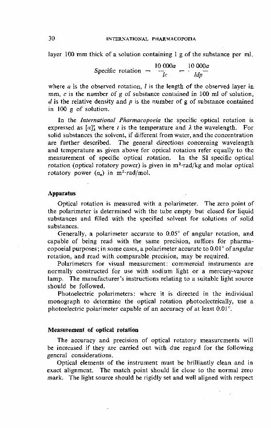
30 INTERNATIONAL PHARMACOPOEIA
layer 100 mm thick of a solution containing 1 g of the substance per ml.
10 OOOa 10 OOOa Specific rotation = ------ - -
l: I ~ P
where a is the observed rotation, l is the length of the observed layer in mm, c is the number of g of substance contained in 100 m1 of solution, d is the relative density and p is the number of g of substance contained in 100 g of solution.
In the International Pharmacopoeia the specific optical rotation is expressed as [a]: where t is the temperature and 1 the wavelength. For solid substances the solvent, if different from water, and the concentration are further described. The general directions concerning wavelength and temperature as given above for optical rotation refer equally to the measurement of specific optical rotation. In the S1 specific optical rotation (optical rotatory power) is given in m2.rad/kg and molar optical rotatory power (a,) in m2-rad/mol.
Apparatus
Optical rotation is measured with a polarimeter. The zero point of the polarimeter is determined with the tube empty but closed for liquid substances and filled with the specified solvent for solutions of solid substances.
Generally, a polarimeter accurate to 0.05" of angular rotation, and capable of being read with the same precision, suffices fdr pharma- copoeial purposes; in some cases, a polarimeter accurate to 0.01" of angular rotation, and read with comparable precision, may be required.
Polarimeters for visual measurement: commercial instruments are normally constructed for use with sodium light or a mercury-vapour lamp. The manufacturer's instructions relating to a suitable light source should be followed.
Photoelectric polarimeters: where it is directed in the individual monograph to determine the optical rotation photoelectrically, use a photoelectric polarimeter capable of an accuracy of at least 0.01 ".
Measurement of optical rotation
The accuracy and precision of optical rotatory measurements will be increased if they are carried out with due regard for the following general considerations.
Optical elements of the instrument must be brilliantly clean and in exact alignment. The match point should lie close to the normal zero mark. The light source should be rigidly set and well aligned with respect

OPTICAL ROTATION, SPECIFIC ROTATION 3 1
to the optical bench. It should be supplemented by a filtering system capable of transmitting light of a sufficiently monochromatic nature. Pre- cision polarimeters are generally designed to accommodate interchange- able discs to isolate the D line from sodium light or the 546.1 nm line efrom the mercury spectrum. With polarimeters not thus designed, cells containing suitably coloured liquids may be employed as filters.
Observations should be accurate and reproducible to the extent that differences between replicates, or between observed and true values of rotation (the latter value having been established by calibration of the polarimeter scale with suitable standards), shall not exceed one-fourth of the range given in the individual monograph for the rotation of the substance being tested.
Polarimeter tubes should be filled in such a way as to avoid creating or leaving air bubbles, which interfere with the passage of the beam of light. Interference from bubbles is minimized by the use of tubes in which the bore is expanded at one end. However, with tubes of uniform bore, such as semi-micro or micro tubes, care is required for proper filling.
In closing tubes having removable end-plates fitted with gaskets and caps, the latter should be tightened only enough to ensure a leak-proof seal between the end-plate and the body of the tube. Excessive pressure on the end-plate may set up strains that result in interference with the measurement. In determining the optical rotation of a substance of low rotatory power, it is desirable to loosen the caps and tighten them again between successive readings in the measurement of both the rotation and the zero point. In this way, differences arising from end-plate strain will generally be revealed and appropriate adjustments to eliminate the cause can be made.
The requirements for optical rotation and specific rotation apply to the dried, anhydrous, or solvent-free material in all those monographs in which standards for loss on drying, water, or solvent content are given. In calculating the result, the loss on drying, water, or solvent content determined by the method specified in the monograph should be taken into account.
RECOMMENDED PROCEDURE
If the substance is a solid, weigh a suitable portion and transfer it to a volumetric flask by means of water, or other solvent if specified in the monograph, reserving a portion of the solvent for the blank determination. Add enough solvent to bring the meniscus close to, but still below, the mark, and adjust the temperature of the flask contents by suspending the flask in a constant-temperature bath. Add solvent to the mark, and mix. Transfer the solution to the polarimeter tube, preferably within 30 minutes from the time the substance was dissolved, taking care
32 INTERNATIONAL PHARMACOPOEIA
to standardize the elapsed time in the case of substances known to undergo racemization or mutarotation. During the elapsed time interval, maintain the solution at the required temperature.
If the substance is a liquid, adjust its temperature, if necessary, and transfer it directly to the polarimeter tube.
When a polarimeter is used for visual measurement, make at least 6 readings of the observed rotation at the required temperature. Take half the readings in a clockwise and the other half in a counterclockwise direction. Substitute the reserved solvent for the solution, and make an equal number of readings on it. In the case of liquid substances, carry out blank determinations on the empty, dry tube. The zero correc- tion is the average of the blank readings, and is subtracted from the average observed rotation if the two figures are of the same sign, or added if they are opposite in sign, to give the corrected observed rotation.
When a photoelectric polarimeter is used, a smaller number of readings is required, depending on the type of instrument.
DETERMINATON OF REFRACTIVE INDEX
The refractive index (n) of a substance is the ratio of the velocity of light in a vacuum to its velocity in the substance. It varies with the wavelength of the light used in its measurement and with the temperature. It is therefore necessary to specify these conditions (n:). In practice it is usually convenient to measure the refraction with respect to air and the substance, rather than with respect to a vacuum and the substance, since, for pharmacopoeial purposes, this has no significant influence on the observed values.
The refractive index may also be defined as the ratio of the sine of the angle of incidence to the sine of the angle of refraction.
The measurement of the refractive index is employed for pharmaco- poeial purposes mainly to establish the identity of liquid substances. It may also be used to test the purity of such substances.
Refractive indices are usually stated in terms of sodium light of wavelength 589.3 nm (line D) at a temperature of 20 f 0.5 "C (nLO).
The accuracy of the measurement should be related to the requirements of the monograph. For pharmacopoeial purposes it is usually adequate to express the refractive index to three decimal places.
Apparatus
Commercial refractometers are normally constructed for use with white light but are calibrated to give the refractive index in terms of the sodium light of wavelength 589.3 nm (line D).

SPECTROPHOTOMETRY-VISIBLE AND ULTRAVIOLET REGIONS 33
The optical parts of the apparatus should be kept brilliantly clean. The working surfaces of prisms should be free from scratches.
Subject to the directions given above, the manufacturer's instructions relating to a suitable light source should be followed.
The instrument should be calibrated against a standard provided by the manufacturer; the temperature control of the liquid being examined and the cleanliness of the prism should be checked frequently by deter- mining the refractive index of distilled water, which is 1.3330 at 20 "C and 1.3325 at 25 "C.
SPECTROPHOTOMETRY IN THE VISIBLE AND ULTRAVIOLET REGIONS
Absorption spectrophotometry is the measurement of the absorption, by substances, of electromagnetic radiation of definite and narrow wave- length range, essentially monochromatic.
The spectral range used in the measurements described below extends from the short wavelengths of the ultraviolet through the visible region of the spectrum. For convenience of reference, this range may be regarded as consisting of two regions, the ultraviolet (190-380 nm) and the visible (380-780 nm).
Spectrophotometry in the visible region (formerly the term colorimetry was commonly used) is the measurement of absorption of visible light, which is usually not monochromatic but restricted by the use of pigmented or interference filters.
The ultraviolet and visible spectra of a substance generally do not have a high degree of specificity. Nevertheless, they are highly suitable for quantitative assay, and for many substances they are useful as addi- tional means of identification.
General agreement has not yet been reached on the definition of terms used in spectrophotometry. The terms in italics used in connexion with spectrophotometric tests in the International Pharmacopoeia are defined as follows:
Absorbance (A) - The logarithm, to the base 10, of the reciprocal of the transmittance (T). The term internal transmission density may be used as a synonym of absorbance; descriptive terms formerly used included optical density, absorbancy, and extinction.
Transmittance (T) - The ratio of the radiant flux transmitted by the test substance to that of the incident radiant flux. Terms formerly used include transmittancy and transmission.

34 INTERNATIONAL PHARMACOPOEIA
Absorptivity (a) - The quotient of the absorbance ( A ) divided by the product of the concentration of the substance (c), expressed in g per litre, and the absorption path length (b) expressed in cm (a = Albc). Two terms closely related to absorptivity are specific extinction and specific absorption coefficient. The term "specific extinction" ( E : as generally used in pharmacopoeias, denotes the quotient of the absorbance (A) divided by the product of the concentration of the substance (c), expressed in g per 100 ml, and the absorption path length (b) expressed in cm; therefore E: ii = lOa. The term "specific absorption coef- ficient", tentatively proposed by the Commission on Physicochemical Symbols, Terminology and Units of the International Union of Pure and Applied Chemistry (IUPAC), is defined as the quotient of absorbance (A) divided by the product of concentration (c) and the absorption path length (l); when the symbol as, is utilized for specific absorption coef- ficient, which in the S1 should be expressed in m2 per kg, as1 = 100a. The term " absorptivity " is not to be confused with absorbancy index or extinction coefficient.
Molar absorptivity ( E ) - The quotient of the absorbance ( A ) divided by the product of the concentration of the substance (c), expressed in moles per litre, and the absorption path length (b) in cm. It is also the product of the absorptivity (a) and the molecular weight of the substance. The term molar absorption coefficient (linear) recommended by the Commission on Physicochemical Symbols, Terminology and Units of IUPAC is defined as the quotient of the internal transmission density (absorbance) of the substance divided by the product of the concentration of the substance and the absorption path length, and according to the S1 should be expressed in m2 per mole. The terms formerly used for molar absorptivity include molar absorbancy index and molar extinction coefficient.
Absorption spectrum - The relationship of absorbance and wave- length or any functions of these, frequently represented in a graphic form.
The use of absorption spectrophotometry in the visible and ultraviolet regions for assay procedures is based on the fact that the absorptivity of a substance is usually a constant independent of the intensity of the incident radiation, the internal cell length, and the concentration, with the result that concentration may be determined photometrically.
Deviations from the above may be caused by either physical, chemical, or instrumental variables. Deviations due to instrumental error might be caused by slit-width effects, stray light, or by polychromatic radiation. Apparent failure may also result from a concentration change in solute molecules because of association between solute molecules or between solute and solvent molecules, or dissociation or ionization.

SPECTROPHOTOMETRY-VISIBLE AND ULTRAVIOLET REGIONS 35
Apparatus
In essence all types of spectrophotometer are designed to permit substantially monochromatic radiant energy to be passed through the test substance in a suitable form and to allow measurement of the fraction of that energy that is transmitted. The spectrophotometer comprises an energy source, a dispersing device with slits for selecting the wave- length band, a cell or holder for the test substance, a detector of radiant energy, associated amplifiers, and measuring and recording devices. Some instruments are manually operated, while others are equipped for automatic operation. Instruments are available for use in the visible region of the spectrum, usually 380 nm to about 700 nm, and in the visible and ultraviolet regions of the spectrum, usually 190 nm to about 700 nm.
Both double-beam and single-beam instruments are commercially available and either is suitable. Depending on the type of apparatus used, the results may be displayed on a scale, on a digital counter, or by a recorder or printer.
The apparatus should be maintained in proper working condition. The housing of the optical system should minimize any possibility of errors due to stray light; this is particularly relevant in the short-wave region of the spectrum.
Cells usually used in the spectral range discussed are l-cm absorption cells with glass or silica windows. Other path lengths may also be used. The cells used for the test solution and the blank should be matched, and must have the same spectral transmittance when containing only the solvent. If this is not the case, an appropriate correction must be applied.
Spectrophotometer calibration
Spectrophotometers should be regularly checked for accuracy of calibrations. Where a continuous source of radiant energy is used, both the wavelength and photometric scales should be calibrated; where a spectral line source is used, only the photometric scale need be checked.
A number of sources of radiant energy have spectral lines of suitable intensity, adequately spaced throughout the spectral range selected. The exact values for the position of characteristic lines in quartz-mercury arc are 253.7, 302.25, 313.16, 334.15, 365.48, 404.66 and 435.83 nm. The wavelength scale may also be calibrated by means of suitable glass filters that have useful absorption bands through the visible and ultra- violet regions. Standard glass containing didymium (a mixture of praseodymium and neodymium) has been widely used. Glass containing holmium is considered superior. The exact values for the position of characteristic maxima in holmium glass filters are 241.5 f 1 , 287.5 f 1,
36 INTERNATIONAL PHARMACOPOEIA
360.9 f 1 and 536.2 f 3 nm. Holmium glass filters are obtainable from some national institutions and from commercial sources. The performance of an uncertified filter should be checked against one that has been properly certified. The wavelength scale may also be calibrated using holmium perchlorate TS. The exact values for the position of characteristic maxima of this solution are as follows : 241.15 nm, 278.2 nm, 361.5 nm and 536.3 nm. It should be noted that the position of charac- teristic maxima of holmium perchlorate solutions and holmium glass filters may differ slightly.
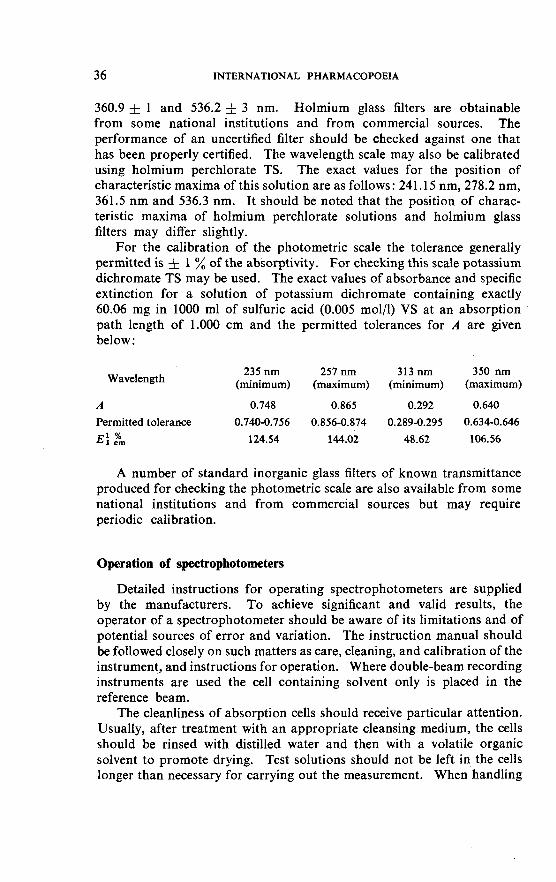
For the calibration of the photometric scale the tolerance generally permitted is f 1 % of the absorptivity. For checking this scale potassium dichromate TS may be used. The exact values of absorbance and specific extinction for a solution of potassium dichromate containing exactly 60.06 mg in 1000 m1 of sulfuric acid (0.005 mol/l) VS at an absorption path length of 1.000 cm and the permitted tolerances for A are given below :
Wavelength 235 nm 257 nm 313 nm 350 nm
(minimum) (maximum) (minimum) (maximum)
A 0.748 0.865 0.292 0.640
Permitted tolerance 0.740-0.756 0.856-0.874 0.289-0.295 0.634-0.646
E: ,%, 124.54 144.02 48.62 106.56
A number of standard inorganic glass filters of known transmittance produced for checking the photometric scale are also available from some national institutions and from commercial sources but may require periodic calibration.
Operation of spectrophotometers
Detailed instructions for operating spectrophotometers are supplied by the manufacturers. To achieve significant and valid results, the operator of a spectrophotometer should be aware of its limitations and of potential sources of error and variation. The instruction manual should be followed closely on such matters as care, cleaning, and calibration of the instrument, and instructions for operation. Where double-beam recording instruments are used the cell containing solvent only is placed in the reference beam.
The cleanliness of absorption cells should receive particular attention. Usually, after treatment with an appropriate cleansing medium, the cells should be rinsed with distilled water and then with a volatile organic solvent to promote drying. Test solutions should not be left in the cells longer than necessary for carrying out the measurement. When handling

SPECTROPHOTOMETRY-VISIBLE AND ULTRAVIOLET REGIONS 37
the cells, special care should be taken never to touch the external surfaces through which the light beam passes. When the solvent and the test solution are transferred to the cells, care is to be taken that the liquids do not contaminate the outer surfaces.
Solvents for use in the ultraviolet region
Many solvents are suitable for tests and assays using spectrophotometry in the ultraviolet region. Water, alcohols, chloroform, lower hydrocar- bons, ethers, and dilute solutions of ammonium hydroxide, sodium hydroxide, sulfuric acid and hydrochloric acid can be used for this purpose. The solvents differ as to the lower wavelength at which the decrease in transparency prevents their use. Precautions should be taken to use solvents free from contaminants absorbing in the relevant spectral region. Specially purified solvents for spectrophotometric determinations are available commercially from several sources but need only be used when the spectral characteristics of the usual analytical grade of solvent are inadequate for a particular purpose.
The absorbance of the solvent cell and its contents should not exceed 0.4 per cm of path length when measured with reference to air at the same wavelength. The solvent in the solvent cell should be of the same batch as that used to prepare the solution and must be free from fluor- escence at the wavelength of measurement. Ethanol (-750 g/l), dehy- drated ethanol, methanol, and cyclohexane used as solvents should have an absorbance, measured in a l-cm cell at 240 nm with reference to water, not exceeding 0.10.
Identification tests in the ultraviolet region
The monographs describing qualitative tests involving spectrophoto- metry in the ultraviolet region specify the concentration of the solution and the path length. In such tests it is more convenient to use a recording instrument. If the conditions stated are not appropriate for a particular instrument, the thickness of the solution should be varied and not the concentration.
Some identification tests involving spectrophotometry require the use of reference substances, generally an International Chemical Reference Substance. The reference substance is then to be prepared and simul- taneously measured under conditions identical for all practical purposes to those used for the test substance. Unless otherwise specified in the monograph, in making up the solution of the reference substance, a solution of about the desired concentration (i.e. within 10 % of the value) should be prepared. Identical conditions for the measurement include

3 8 INTERNATIONAL PHARMACOPOEIA
the following: wavelength setting, slit-width adjustment, cell placement, and correction and transmittance levels.
A useful approach for identification tests in the ultraviolet region is to quote the ratio of absorbance values at two maxima. This procedure minimizes the influence of instrumental variations on the test and obviates the need for a reference substance.
Quantitative determinations in the ultraviolet region
Spectrophotometric assays usually call for a comparison of the absorbance produced by the solution of the test substance, prepared as specified in the monograph, with the absorbance of a solution of a reference substance. In such cases the spectrophotometric measure- ments are made first with the solution prepared from the reference substance and secondly with the solution prepared from the substance to be examined. The second measurement is carried out as quickly as possible after the first, using the same experimental conditions.
Spectrophotometric assays are usually carried out at a peak of spectral absorption for the compound concerned. The monographs give the commonly accepted wavelength for peak spectral absorption of the substance in question. It is known that different spectrophotometers may show minor variations in the apparent wavelength of this peak. Good practice demands that use be made of the peak wavelength actually found in the individual instrument, rather than the specific wavelength given in the monograph, provided the two do not differ by more than 5 0.5 nm in the 240-280 nm range, by more than f 1 nm in the 280- 320 nm range, and by more than f 2 nm above 320 nm. If the difference is greater, recalibration of the instrument may be indicated.
The solution of the reference substance, generally an International Chemical Reference Substance, is to be prepared and measured in the same manner as described for "Identification tests in the ultraviolet region". The calculations should be made on the basis of the exact amount weighed and, if the reference substance used has not previously been dried, on the dried or anhydrous basis. Specific instructions in individual monographs indicate the manner in which a reference substance is to be dried or treated prior to use. These instructions are to be followed unless otherwise specified in the individual test or assay, or in the labelling.
To ensure that the conditions used are appropriate the monograph . may also specify the value of absorbance of a l-cm layer of the reference
substance. In this case the determination carried out against the reference substance is considered valid when the observed value of absorbance is within the range of values specified in the monograph.

SPECTROPHOTOMETRY-VISIBLE AND ULTRAVIOLET REGIONS 39
For quantitative work, a manually scanning instrument is frequently used. When a recording instrument is used for that purpose special attention should be paid to proper calibration of the absorbance scale at the wavelength used.
Quantitative determinations are usually carried out at wavelengths above 235 nm. If the measurements are to be made at a wavelength in the 190-210 nm range, special precautions should be observed, for example, purging the cell compartment with nitrogen, use of solvents of special spectrophotometric quality, and using cells that are transparent in this region.
When measuring the absorbance at an absorption maximum the spectral slit-width must be small compared with the half width of the absorption band, otherwise an erroneously low absorbance will be measured. Particular care is needed for certain substances and the instrumental slit-width used should always be such that further reduction does not result in an increased absorbance reading. Problems may be encountered, owing to diffraction of the light beam, at slit-widths below 0.01 mm.
When the assays are carried out with routine frequency it is permissible to omit the use of a reference substance and use instead a suitable standard curve prepared with the respective International Chemical Reference Substance. This may be done when, for the substance tested, the absorb- ance is proportional to the concentration within the range of about 75-125 % of the final concentration used in the assay. Under these circumstances, the absorbance found in the assay may be interpolated on the standard curve, and the assay result calculated therefrom. Such standard curves should be confirmed frequently, and always when a new apparatus or new lots of reagents are put into use. In the event of uncertainty or dispute, direct comparison with an International Chemical Reference Substance must be made.
Quantitative determinations in the visible region
Spectrophotometric assays in the visible region, as in the ultraviolet region, usually call for simultaneous comparison of the absorbance produced by the assay preparation with that produced by a standard preparation containing approximately an equal quantity of a reference substance.
For spectrophotometric assays in the visible region the recommen- dations given under "Quantitative determinations in the ultraviolet region", including those concerning the use of standard curves, should be followed with suitable modifications, where necessary. In this region, observed wavelengths should not differ by more than 5 nm from that specified in the monograph.

INTERNATIONAL PHARMACOPOEIA
SPECTROPHOTOMETRY IN THE INFRARED REGION
The infrared region of the electromagnetic spectrum used in pharma- ceutical analysis covers the range 4000-250 cm-' (2.5-40 pm).'
Spectrophotometric measurements in the infrared region are used mainly as an identification test. The infrared spectrum is unique for any given chemical compound with the exception of optical isomers, which have identical spectra in solution. Polymorphism and other factors, such as variations in crystal size and orientation, the grinding procedure, and the possible formation of hydrates may, however, be responsible for a difference in the infrared spectrum of a given compound in the solid state. The infrared spectrum is usually not greatly affected by the presence of small quantities of impurities (up to several percent) in the tested substance. For identification purposes the spectrum may be compared with that of a reference substance, concomitantly prepared or with a standard reference spectrum.
The terms absorption spectrum, absorbance, transmittance, absorp- tivity, and specific extinction are described in "Spectrophotometry in the visible and ultraviolet regions7' (see page 33).
Apparatus
Spectrophotometers for the infrared region are basically similar to those used for the visible and ultraviolet regions of the spectrum, but may differ as to the energy sources, optical materials, and detection devices. Furthermore, in some instruments the monochromator may be located between the test substance and the detector.
Spectrophotometers suitable for use for identification tests should operate in the range 4000-670 cm-' (2.5-15 pm). They should be checked frequently to ensure that they meet the standards of performance laid down by the manufacturer of the instrument, including the relia- bility of the wavelength scales, which should be checked by use of a poly- styrene film.
For the use of the attenuated total reflectance technique, the instrument should be equipped with a suitable attachment, which may be a single- reflection or a multi-reflection one. The attachment consists of a reflec- ting element and a suitable mounting permitting its alignment in the spectrophotometer for maximum transmission.
l The values given in brackets are wavelengths; the preceding values are wave- numbers, which are the reciprocals of the wavelengths.

SPECTROPHOTOMETRY-INFRARED REGION 41
Use of solvents
The solvent used in infrared spectrophotometry must not affect the material, usually sodium chloride, of which the cell is made.
No solvent in appreciable thickness is completely transparent through- out the infrared spectrum. Carbon tetrachloride R is practically trans- parent (up to 1 mm in thickness) from 4000 to 1700 cm-' (2.5 to 6 pm). Chloroform R, dichloromethane R, and dibromomethane R are other useful solvents. Carbon disulfide IR (up to 1 mm in thickness) is suitable as a solvent to 250 cm-' (40 pm), except in the 2400-2000 cm-' (4.2- 5.0 pm) and the 1800-1300 cm-' (5.5-7.5 pm) regions, where it has strong absorption. Its weak absorption in the 875-845 cm-' (1 1.4- 11.8 pm) region should also be noted. Other solvents have relatively narrow regions of transparency.
Preparation of the substance to be tested
To determine the infrared absorption spectrum of a substance, the latter has to be suitably prepared. Liquid substances may be tested directly or in a suitable solution. For solid substances, the usual methods of preparation include dispersing the finely ground solid specimen in mineral oil, or incorporating it in a transparent disc or pellet obtained by mixing it intimately with previously dried potassium halide and pressing the mixture in a die, or preparing a solution in a suitable solvent. Prepar- ation of the substance for the attenuated total reflectance technique is described separately.
The following procedures may be used for the preparation of the substance:
Method 1. Use a capillary film of the liquid held between two sodium chloride plates or a filled cell of suitable thickness.
Method 2. Triturate a small quantity of the substance with the mini- mum amount of a suitable mineral oil or other suitable liquid to give a smooth, creamy paste; 2-5 mg of the substance being tested is often sufficient to prepare a satisfactory mull, which should be semi-transparent to light. Compress a portion of the mull between two flat sodium chloride or other suitable plates.
Method 3. Triturate the solid substance with dry, finely powdered potassium halide (potassium bromide IR, potassium chloride IR); the proportion of substance to the halide should be about 1 to 200 -, for example, 1.5 mg in 300 mg of the halide - in the case of prism instruments, and about 1 to 300 - for example, 1.0 mg in 300 mg of the halide - in the case of grating instruments. The amount taken should be such that the weight of substance per area of the disc is about 5-15 pg per mm2, varying with the molecular weight and to some degree with the type of

42 INTERNATIONAL PHARMACOPOEIA
apparatus used. Insert a portion of the mixture in a special die and subject it under vacuum to a high pressure. Commercial dies are avail- able and the manufacturer's instructions should be followed. Mount the resultant disc in a suitable holder. Several factors, for example, inadequate or excessive grinding, moisture or other impurities in the halide carrier, may give rise to unsatisfactory discs. Unless its prepar- ation presents particular difficulties, a disc should be rejected if visual inspection shows lack of uniformity or if the transmission at about 2000 cm-l (5 pm) in the absence of a specific absorption band is less than 75 % without compensation.
Method 4. Prepare a solution of the liquid or solid substance in a suitable solvent and choose a concentration and cell thickness to give a satisfactory spectrum over a sufficiently wide wavelength range.
Identification by reference substance
Prepare the substance under examination and the reference substance by the same method, and record the spectrum of each from about 4000 to 670 cm - l (2.5 pm to 15 pm) on an infrared spectrophotometer. The concentration of the substance should be such that the strongest peak attributable to the substance reaches to between 5 % and 25 % transmit- tance.
If the positions and relative intensities of the absorbance maxima in the spectrum of the substance under examination are not concordant with those of the spectrum of the reference substance in the case of the curves obtained by methods 2 or 3, this may be due to differences in crystalline form. When such difficulties are suspected, the substance should, where possible, be examined in solution. If examination in solution is not practicable, attempts should be made to obtain, by recrystal- lization, the reference substance and the substance under examination in the same crystalline form.
If the spectrum of mineral oil used in method 2 interferes with regions of interest, an additional dispersion of the substance in a medium such as a suitable fluorinated hydrocarbon oil or hexachlorobutadiene may be prepared and the spectrum recorded in the regions where the mineral oil shows strong absorption.
Identification by reference spectrum
Prepare the substance being examined exactly as described in the note accompanying the International Reference Spectrum and record the spectrum from about 4000 to 670 cm-' (2.5 to 15 pm) using an instrument that is being checked frequently to ensure that it meets the standards of performance laid down by the manufacturer. To allow for a possible difference in wavelength calibration between the instrument

ATOMIC ABSORPTION SPECTROPHOTOMETRY 43
on which the International Reference Spectrum was obtained and that on which the spectrum of the substance is to be recorded, reference absorb- ance maxima of a polystyrene spectrum are superimposed on the Inter- national Reference Spectrum at about 2851 cm-' (3.51 pm), 1601 cm-' (6.25 pm) and 1028 cm-' (9.73 pm). Similar reference maxima should be superimposed on the spectrum of the substance. Taking these poly- styrene maxima into account, the identification is considered to be positive if the principal absorbance maxima in the spectrum of the substance being tested are concordant with the corresponding maxima in the relevant International Reference Spectrum. When comparing the two spectra, care should be taken to allow for the possibility of differences in resolving power between the instrument on which the International Reference Spectrum was prepared and the instrument being used to examine the substance. An International Reference Spectrum of polystyrene that was recorded on the same instrument as the collection of International Reference Spectra should be used for assessing these differences. It should be noted that the greatest variation due to differences in resolving power is likely to occur in the region between 4000 and 2000 cm-' (2.5 and 5 pm).
Attenuated total reflectance technique
To determine the infrared absorption spectrum of a substance by the attenuated total reflectance technique the solid substance has usually to be finely pulverized. The powder may then be either packed directly against the prism of the attachment or adhesive tape may be used to facilitate the contact. The powdered substance is spread on the adhesive side of an adhesive tape to form an almost translucent layer and the tape is pressed on the reflecting element, on the side with powder in contact. Next, either the backing plate is attached or moderate pressure is applied in a suitable clamp for 1-2 minutes. Finally, the reflecting element is placed in the holder. The tape used in the procedure should preferably contain a natural rubber adhesive. In the case of some plastic materials it may be placed directly on the reflecting element.
Proper alignment of the attachment in the apparatus should be carefully controlled.
ATOMIC ABSORPTION SPECTROPHOTOMETRY
Flame atomic absorption spectrophotometry, or flame absorption spectrophotometry, is a procedure during which atoms, ions, or ion complexes of an element, upon being atomized to the ground state in a flame, absorb light at the characteristic wavelength for that element.

44 INTERNATIONAL PHARMACOPOEIA
If the absorption process takes place in the flame under reproducible conditions, the absorbance (the reciprocal logarithm of the transmittance) is proportional to the number of absorbing atoms. On this basis, cali- bration curves may be constructed to permit evaluation of unknown absorption values in terms of concentration of the element in solution.
It may be noted that besides flame atomic absorption spectrophoto- metry, flameless techniques of atomic absorption spectrophotometry have also been evolved.
Apparatus
A flame atomic absorption spectrophotometer consists of an emission source that provides the characteristic spectral line of the element to be determined, a nebulizer-burner system for introducing the sample solution into a flame, and a detector system.
The emission source is usually a hollow-cathode discharge lamp, the cathode of which is designed to emit the desired radiation when excited. Since the radiation to be absorbed by the element in the test solution is usually of the same wavelength as that of its emission line, the element in the hollow-cathode lamp will be the same as the element to be determined. In general, a different lamp is used for each element; however, some element combinations are compatible with single lamps now available commercially.
The nebulizer-burner system introduces the test solution into a flame, which is usually provided by air-acetylene or air-hydrogen. The flame, in effect, is a heated sample chamber.
The detector system used to read the signal from the chamber is com- posed of an optical dispersing device, such as a monochromator or a filter for isolating a resonance line of the element, and a radiation detector, such as a photomultiplier and display system to indicate the absorbance.
Interfering radiation produced by the flame during combustion may be negated by the use of a chopped source lamp signal of a definite fre- quency. The detector should then be tuned to the alternating current frequency so that the direct current signal arising from the flame will be ignored. Such a detecting system, therefore, reads only the change in signal from the hollow-cathode source, which is directly proportional to the number of atoms to be determined in the substance.
Use of solvents
An ideal solvent is one that interferes to a minimal extent in the absorp- tion or emission processes and one that produces neutral atoms in the flame. If there is a significant difference between the surface tension or viscosity of the substance and those of the reference solution, the sol-

FLUORESCENCE SPECTROPHOTOMETRY 45
utions will be aspirated or atomized at different rates, causing significant differences in the signals generated. The acid concentration of the sol- utions also affects the absorption process. Therefore, the solvent used in preparing the test solution and that used for the reference solution should be either the same or as much alike as possible in these respects, and should yield solutions that are easily aspirated via the tube of the burner-aspirator. Where solids are present in solutions they may give rise to interferences and for that reason the solid content of the solutions should be below 2 % wherever possible.
RECOMMENDED PROCEDURE
Prepare not fewer than 3 reference solutions of the element to be determined covering the concentration range recommended by the manufacturers for the element and instrument used. Any reagent used in preparing the solution of the substance being examined should be added to the reference solutions in the same concentration.
For measurements on instruments calibrated for transmission, spray water into the flame and adjust the reading to full scale; no further adjustments are necessary for this type of instrument. For instruments calibrated for absorption, refer to the manufacturer's instructions. Spray each reference solution into the flame 3 times, recording the steady reading obtained and washing the apparatus through with water after each spraying. Prepare a calibration curve by plotting the mean of each group of 3 readings against the concentration.
Prepare a solution of the substance being examined as specified in the monograph but adjust the concentration of the element to be determined, if necessary, so that it falls within the concentration range recommended for the instrument used. Spray the solution into the flame 3 times, record the readings and wash the apparatus through with water after each spraying. Use the mean of the readings to determine the concen- tration of the element from the calibration curve.
FLUORESCENCE SPECTROPHOTOMETRY
Fluorescence spectrophotometry is the measurement of the fluorescence, i.e., photoluminescence, emitted by a substance while it is being exposed to ultraviolet, visible, or other electromagnetic radiation. In general, the light emitted by fluorescent solutions is of maximum intensity at a wavelength longer than that of the absorption band causing excitation, usually by some 20 or 30 nm.
46 INTERNATIONAL PHARMACOPOEIA
The intensity of the light emitted by a fluorescent solution is, in certain circumstances, a simple function of the concentration of the solute and can, therefore, be used for analysis. It is difficult, however, to measure absolute fluorescence intensity, and measurements are usually made by reference to dilutions of a properly selected reference substance. The general scheme in fluorescence spectroscopy is therefore to excite with radiation at the wavelength of maximum absorption, and to measure or compare the intensity of the fluorescent light with that of a reference solution. The fluorescent light should be carefully freed from scattered incident light.
Terms
Fluorescence intensity is an empirical expression of fluorescence activity, commonly given in terms of arbitrary units proportional to detector response.
The fluorescence emission spectrum is the relationship between the intensity of the emitted radiation and the wavelength and is frequently represented in a graphic form.
The fluorescence excitation spectrum is the relationship between the maximum intensity of radiation emitted by an activated substance and the wavelength of the incident radiation and is frequently represented in a graphic form.
Apparatus
Measurement of fluorescence intensity can be made with a simple filter fluorimeter (sometimes the term fluorometer is used). Such an instrument consists of a radiation source, a primary filter, a sample chamber, a secondary filter, and a fluorescence detection system. In most such fluorimeters, the detector is placed on an axis at 90" from that of the incident beam. This right-angle geometry permits the incident radi- ation to pass through the test solution without contaminating the output signal received by the fluorescence detector. However, the detector unavoidably receives some of the incident radiation as a result of the inherent scattering properties of the solutions themselves, or if dust or other solids are present. Filters are used to eliminate this residual scatter. The primary filter selects short wavelength radiation capable of causing excitation of the test substance, while the secondary filter is normally a sharp cut-off filter that allows the longer wavelength fluorescence to be transmitted but blocks the scattered excitated radiation.
Most fluorimeters use photomultiplier tubes as detectors; many types are available, each having special characteristics with respect to spectral region of maximum sensitivity, gain, and electrical noise. After ampli-

FLUORESCENCE SPECTROPHOTOMETRY 47
fication of the photocurrent its value is read visually on a measuring device or recorded.
A fluorescence spectrophotometer differs from a filter fluorimeter in that filters are replaced by monochromators, of either the prism or the grating type. For analytical purposes, the fluorescence spectrophotometer is superior to the filter fluorimeter in wavelength selectivity, flexibility, and convenience.
Many radiation sources are used in fluorimeters and fluorescence spectrophotometers. Mercury lamps are relatively stable and emit energy mainly at discrete wavelengths. Tungsten lamps provide an energy continuum in the visible region. The high pressure xenon arc lamp is often used in fluorescence spectrophotometers because it has an energy continuum extending from the ultraviolet into the infrared.
In fluorescence spectrophotometers the monochromators are equipped with slits. A narrow slit provides high resolution and spectral purity, while a large slit sacrifices these for high intensity. Choice of slit-width is determined by the wavelength separation between incident and emitted radiation, as well as by the degree of sensitivity needed.
The cells used in fluorescence measurements may be rectangular cells similar to those used in absorption spectrophotometers, except that they are polished on all 4 vertical sides and on the bottom, or cells in the shape of round tubes with flat polished bottoms may be used. A convenient size is 2-3 ml, but some instruments can be fitted with small cells holding 0.1-0.3 ml, or with a capillary holder requiring even less solution.
Standardization
Fluorimeters and fluorescence spectrophotometers should be stan- dardized daily with a stable fluorophore to assure proper reproducibility of response. The changes are due to instrumental variables such as differences in lamp intensity and photomultiplier sensitivity. The fluoro- phore may be a pure specimen of the fluorescent substance under test or another readily purified fluorescent substance with absorption and fluor- escence bands similar to those of the test substance. Quinine in dilute sulfuric acid is often a convenient fluorophore for blue fluorescence, sodium fluorescein for green fluorescence, and rhodamine for red fluor- escence.
Calibration of the wavelength scale
The wavelength scale of the fluorescence spectrophotometer should be periodically calibrated.

48 INTERNATIONAL PHARMACOPOEIA
Preparation of solution
The solvent used for the measurement should be properly selected. The solvent itself, its purity and its pH may markedly affect the intensity and spectral distribution of fluorescence.
Test solutions prepared for fluorescence spectrophotometry are usually 10 times to 100 times less concentrated than those used in absorp- tion spectrophotometry. In analytical applications, it is necessary that the fluorescence intensity be linearly related to the concentration in the range used for measurements; but if a solution is too concentrated, a significant part of the incident light is absorbed by the substance near the cell surface, thus resulting in a reduction of the light reaching the centre. That is, the substance itself acts as an "inner filter". Fortunately, fluorescence spectrophotometry is inherently a very sensitive technique, and concentrations of 10 - '-1 0 - moll1 are frequently used.
Owing to the usually very narrow range within which the fluorescence is proportional to the concentration of the fluorescent substance, the ratio (c-d)/(a-b), where a is the fluorescence intensity read for the reference substance, b the reading for the corresponding blank, c the fluorescence intensity read for the test substance, and d the reading for the corre- sponding blank, should be not less than 0.40 and not more than 2.50. It is then necessary to make a working curve of fluorescence intensity corrected for a solvent blank versus concentration.
Measurement technique
Fluorescence measurements are sensitive to the presence of solid particles in the test solution. Such impurities may reduce the intensity of the exciting beam or give misleadingly high readings because of multiple reflections in the cell. It is, therefore, wise to eliminate solid particles by centrifugation; filtration may also be used, but some filter-papers may contain fluorescent impurities.
Oxygen dissolved in the solvent has a strong quenching effect. The intensity of fluorescence is therefore increased by use of a degassing procedure, such as bubbling nitrogen or another inert gas through the test solution.
Temperature regulation is often important in fluorescence spectro- photometry. For some substances, fluorescence efficiency may be reduced by as much as 1-2 % per degree of temperature rise. In such cases, if maximum precision is desired, temperature-controlled sample cells are essential. For routine analysis, it may be sufficient to make measure- ments rapidly enough so that the test solution does not heat up appreci- ably from exposure to the intense light source.
Many fluorescent compounds are light-sensitive. Exposed in a

TURBIDIMETRY, NEPHELOMETRY 49
fluorescence spectrophotometer, they may be photodegraded into more or less fluorescent products. Such effects may be detected by observing the detector response in relation to time, and may be reduced by attenu- ating the light source with filters or screens.
TURBIDIMETRY AND NEPHELOMETRY
Turbidimetry is the measurement of the degree of attenuation of a radiant beam incident on particles suspended in a medium, the measure- ment being made in the directly transmitted beam. It may be measured with a standard photoelectric filter photometer or spectrophotometer with illumination at an appropriate wavelength.
Nephelometry is the measurement of the light scattered by suspended particles, the measurement usually being made perpendicularly to the incident beam.
Turbidimetry or nephelometry may be useful for the measurement of precipitates formed by the interaction of very dilute solutions of reagents, or other particulate matter, such as suspensions of bacterial cells. In order that consistent results may be achieved, all variables must be carefully controlled. Problems due to birefringence may be encountered, particularly with bacterial cells. Where proper control is possible, ex- tremely dilute suspensions may be measured.
Terms
Transmittance ( T ) - The ratio of the radiant flux transmitted by the test substance to that of the incident radiant flux. Terms formerly used include transmittancy and transmission.
Turbidance ( S ) - A measure of the light-scattering effect of suspended particles.
Turbidity (-c) - In light-scattering measurements, the turbidity is the measure of the decrease in incident beam intensity per unit length of a given suspension.
Apparatus
Turbidity may be measured with a standard photoelectric filter photo- meter or spectrophotometer, preferably with illumination in the red- orange region of the spectrum (for example, by using a blue filter).

50 INTERNATIONAL PHARMACOPOEIA
Nephelometric measurements require an instrument with a photocell placed so as to receive scattered rather than transmitted light; as this geometry applies also to fluorimeters in general, the latter can be used as nephelometers by proper selection of filters.
Instrumental measurement
For instrumental measurement it is advisable to ensure that settling of the particles being measured will be negligible. This is usually accomp- lished by including a protective colloid in the liquid suspending medium. It is important that results be interpreted by comparison of readings with those representing known concentrations of suspended matter, produced under exactly the same conditions.
Visual comparison
Carry out turbidity comparison in tubes that are matched as closely as possible in internal diameter and in all other respects. Flat-bottomed comparison tubes of transparent glass of about 70 m1 capacity and about 23 mm internal diameter are suitable. For turbidity comparison the tubes should be viewed horizontally, against a dark background, with the aid of a light source directed from the sides of the tubes.
COLOUR OF LIQUIDS
The test for colour of liquids is carried out by comparing the test solution prepared as specified in the monograph with a standard colour solution indicated in the monograph. The composition of the standard colour solution is selected depending on the hue and intensity of the colour of the test solution corresponding to the limits permitted in the specifications.
RECOMMENDED PROCEDURE
Unless otherwise specified in the monograph, carry out the comparison in flat-bottomed tubes of transparent glass that are matched as closely as possible in internal diameter and in all other respects (tubes of about 16 mm internal diameter are suitable). Use 10 m1 of the test solution and 10 m1 of the standard colour solution; the depth of liquid should be about 50 mm. The colour of the test solution is not more intense than the standard colour when viewed down the vertical axis of the tubes in diffused light against a white background.

COLOUR OF LIQUIDS
Stock Colour Standard Solutions
Yellow stock standard TS
To 9.5 ml of cobalt colour TS, add 1.9 m1 of copper colour TS, 10.7 m1 of dichromate colour TS, 4.0 m1 of iron colour TS, dilute to 100.0 m1 with sulfuric acid (-10 g/l) TS, and mix.
Red stock standard TS
To 40.5 m1 of cobalt colour TS, add 6.1 m1 of copper colour TS, 6 .3 ml of dichromate colour TS, 12.0 m1 of iron colour TS, dilute to 100.0 ml with sulfuric acid (-10 g/l) TS, and mix.
Green stock standard TS
To 3.5 ml of cobalt colour TS, add 20.1 m1 of copper colour TS, 10.4 m1 of dichromate colour TS, 4.0 m1 of iron colour TS, dilute to 100.0 m1 with sulfuric acid (-10 g/l) TS, and mix.
Brown stock standard TS
To 35.0 ml of cobalt colour TS, add 17.0 m1 of copper colour TS, 8.0 ml of dichromate colour TS, dilute to 100.0 ml with iron colour TS, and mix.
Standard Colour Solutions
The standard colour solution is prepared by suitably diluting the stock standard solutions (yellow, red, green, and brown stock standard TS) with sulfuric acid (-10 g/l) TS. The designation of the standard colour solution is composed of two letters indicating the stock standard solution (Yw for yellow, Rd for red, Gn for green, and Bn for brown) and of a number describing the dilution, as given below :
Dilutiot~ number for standard
colour solutions
Stock standard solution
(tnl)
Sulfuric acid (-10 gll) TS
f

52 INTERNATIONAL PHARMACOPOEIA
Standard colour solution numbers 4-7 may be stored in sealed glass containers, protected from sunlight but the more dilute standard colour solutions should be prepared as required.
RADIOPHARMACEUTICALS
The handling and testing of radiopharmaceuticals (radioactive pharma- ceuticals) require specialized techniques in order that correct results may be obtained and hazards to personnel minimized. All operations should be carried out or supervised by personnel who have received expert training in handling radioactive materials.
Definitions
Nuclide
A species of atom characterized by its mass number, atomic number, and nuclear energy state, provided that the mean life in that state is long enough to be observable.
Radioactivity
The property of certain nuclides of emitting radiation by the spon- taneous transformation of their nuclei into those of other nuclides.
EXPLANATORY NOTE. The term "desintegration" is widely used as an alternative to the term "transformation". Transformation is preferred as it includes, without semantic difficulties, those processes in whicH no particles are emitted from the nucleus.
Radionuclide
A nuclide that is radioactive.
Units of radioactivity
The activity of a quantity of radioactive material is expressed in terms of the number of nuclear transformations taking place in unit time. The S1 unit of activity is the becquerel (Bq), a special name for the reciprocal second (S-'). The expression of activity in terms of the becquerel there- fore indicates the number of disintegrations per second. One curie (Ci) equals 3.7 X 101° Bq.
The conversion factors between becquerel and curie and its sub- multiples are given in "Units of measurement" (see page 14).
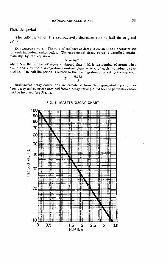
RADIOPHARMACEUTICALS 53
Half-life period
The time in which the radioactivity decreases to one-half its original value.
EXPLANATORY NOTE. The rate of radioactive decay is constant and characteristic for each individual radionuclide. The exponential decay curve is described mathe- matically by the equation
N = N0e-at where N is the number of atoms at elapsed time t, No is the number of atoms when t = 0, and h is the disintegration constant characteristic of each individual radio- nuclide. The half-life period is related to the disintegration constant by the equation
0.693 Tl = -
il Radioactive decay corrections are calculated from the exponential equation, or
from decay tables, or are obtained from a decay curve plotted for the particular radio- nuclide involved (see Fig. 1).
FIG. 1. MASTER DECAY CHART

54 INTERNATIONAL PHARMACOPOEIA
Radioactive concentration
The radioactive concentration of a solution refers to the radioactivity in a unit volume of the solution. As with all statements involving radio- activity, it is necessary to include a reference date of standardization. For radionuclides with a half-life period of less than 30 days, the time of standardization should be expressed to the nearest hour. For radio- nuclides with a half-life period of less than one day, a more precise statement of the reference time is required.
Specific radioactivity (or specific activity)
The specific activity of a preparation of a radioactive material is the radioactivity per unit mass of the element or of the compound concerned.
EXPLANATORY NOTE. It is usual to specify the radionuclide concerned and also it is necessary to express the time thus: "1 mCi of iodine-131 per mg of o-iodohippuric acid at 12.00 hours UT on 1 January 1979", or "40 MBq of selenium-75 per mg of selenomethionine on 1 January 1979".
Specific radioactivity is often not determined directly but is calculated from a knowledge of the radioactive concentration of the solution and of the chemical concen- tration of the radioactive compound. Thus, if a solution contains x mCi of 13'1 per ml, and if the 13' I is entirely in the chemical form of sodium o-iodohippurate of which the concentration is y mg per ml, then at that time the specific activity is:
x /y mCi of iodine-I31 per mg of o-iodohippuric acid.
Where necessary, the radiochemical purity of the preparation (see below) must be taken into account.
The term employed in radiochemical work is "specific activity". As the word, "activity" has other connotations in a pharmacopoeia, the term should, where necessary, be modified to "specific radioactivity" to avoid ambiguity.
Radionuclidic purity
The radionuclidic purity of a preparation is that percentage of the total radioactivity that is present in the form of the stated radionuclide.
EXPLANATORY NOTE. Some radionuclides decay into nuclides that are themselves radioactive: these are referred to as mother (or parent) and daughter radionuclides respectively. Such daughter radionuclides are often excluded when calculating the radionuclidic purity; for example, iodine-131 will always contain its daughter xenon- 131m, but this would not be considered an impurity because its presence is unavoidable.
In employing the definition, the radioactivity must be measured in appropriate units: that is, in the number of nuclear transformations that occur in unit time (in terms of curies or becquerels). If, for example, a preparation stated to be iodine- 125 is known to contain 99 mCi of iodine-125 and 1 mCi of iodine-126, and no other radionuclide, then the preparation is said to be of 99 % radionuclidic purity. It will be noted that the relative amounts of iodine-125 and iodine-126, and hence the radio- nuclidic purity, will change with time. An expression of radionuclidic purity must therefore contain a statement of the time, such as: "Not more than 1 % of the total radioactivity is due to iodine-126 at the reference date stated on the label". In the case

of radionuclides with a half-life period of less than 30 days the reference hour should also be included.
It is clear that, in order to give a statement of the radionuclidic purity of a prepara- tion, the activities (and hence the identities) of every radionuclide present must be known. There are no simple and certain means of identifying and measuring all the radionuclidic impurities that might be present in a preparation. An expression of radionuclidic purity must either depend upon the judgement of the person concerned, or it must be qualified by reference to the method employed, for example : "No radio- nuclidic impurities were detected by gamma scintillation spectrometry using a sodium iodide detector."
Radiochemical purity
The radiochemical purity of a preparation is that percentage of the stated radionuclide that is present in the stated chemical form. As radio- chemical purity may change with time, mainly because of radiation decomposition, the time at which the radiochemical purity limit is appli- cable must be specified.
EXPLANATORY NOTE. If, for example, a preparation of cyanocobalamin (57Co) is stated to be 99 % radiochemically pure, then 99 of the cobalt-57 is present in the form of cyanocobalamin. Radiochemical impurities might include such substances as cobaltous (57Co) ion or hydroxycobalarnin (57Co).
The possible presence of radionuclidic impurities is not taken into account in the definition. If the radionuclidic impurity is not isotopic with the stated radionuclide, then it cannot possibly be in the identical chemical form. If the radionuclidic impurity is isotopic with the stated radionuclide, it could be, and indeed is likely to be, in the same chemical form.
Radiochemical impurities may arise during the preparation of the material or during storage, because of ordinary chemical decomposition or, what is often more important, because of radiation decomposition (that is, because of the physical and chemical effects of the radiation).
Production and Handling of Radiopharmaceuticals
The following paragraphs concern special considerations applying to the monographs on radiopharmaceuticals. The facilities for the production, use, and storage of radiopharmaceuticals are generally subject to licensing by national authorities. They often have to comply with 2 sets of regulations, those concerned with pharmaceutical prep- arations and those concerned with radioactive materials. Each producer or user must be thoroughly cognizant of the national requirements pertaining to the articles concerned.
Carriers
The mass of radioactive material usually encountered in radioactive pharmaceuticals is often too small to be measured by ordinary chemical or physical methods. Since such small amounts may not be subject

56 INTERNATIONAL PHARMACOPEIA
to the usual methods of separation and purification, a carrier, in the form of inactive material, either isotopic with the radionuclide, or non-isotopic, but chemically similar to the radionuclide, may be added during proces- sing and dispensing to permit ready handling. Thus sodium phosphate carrier is present in "Natrii Phosphatis ("P) Injectio" and rhenium is used as a carrier in certain colloidal preparations of technetium-99m. The amount of carrier added must be sufficiently small for it not to cause undesirable physiological effects. The mass of an element formed in a nuclear reaction may be exceeded by that of the inactive isotope present in the target material or in the reagents used in the separation procedures.
Radioactive preparations in which no carrier is intentionally added during the manufacture or processing are often loosely referred to as carrier-free.
Detection and Measurement
Radioactive transformations may involve the emission of charged particles, the process of electron capture, or the process of isomeric tran- sition. The charged particles emitted from the nucleus may be alpha- particles (helium nuclei of mass number 4) or beta particles (electrons of negative or positive charge, p-- or p+ respectively, the latter known as positrons). The emission of charged particles from the nucleus may be accompanied by gamma rays, which are of the same physical nature as X-rays. Gamma rays are also emitted in the process of isomeric transition (i.t.). X-rays, which may be accompanied by gamma rays, are emitted in the process of electron capture (e.c.). Positrons are annihilated on contact with matter. Each positron annihilated is accompanied by the emission of 2 gamma rays, each with an energy of 0.51 1 MeV.
The physical characteristics of radionuclides are summarized in Table 1.
The methods employed for the detection and measurement of radio- activity are dependent upon the nature and energy of the radiation emitted. Radioactivity may be detected and/or measured by a number of different instruments based upon the action of radiation in causing the ionization of gases and solids, or the fluorescence of certain solids and liquids, or by the effect of radiation on a photographic emulsion.
In general, a counting assembly consists of a sensing unit and an electronic scaling device. The sensing unit may be a Geiger-Miiller tube, a proportional counter, a scintillation detector in which a photomultiplier tube is employed in conjunction with a scintillator, or a solid-state semi- conductor.
Geiger-Miiller counters and proportional counters are generally used for the measurement of the beta emitters. Scintillation counters

TABLE 1. PHYSICAL CHARACTERISTICS OF RADIONUCLIDES
Nuclide
Part~cle energies and transition roba abilities Electromagnetic transitions
Half- T..-- oi -ciecayb . :a!-- transitions life ,v.>-
period* energy Lrarlslllorl MeV probability photon energy MeV photons emitted internally
converted
. . . . . . . . . . . . . . . . . . . . . . . . . . . . . . . . . . . . . . . . . . . . . . . via 2.6 min '37mBa 0.662 85.1 % 9.5 %
F El
0.032-0.038 8 % (Ba K X-rays) g
Chromium-51 27.7 d ex. 100 % 0.320 9.83 % p 5
0.005-0.006 -22 % (V K X-rays) 5 '2
100 % 0.01 4 9.4 % 78.0 % 0.1 22 85.2 % 2.0 % 0.1 36 11.1 % 1.5 % 0.570 0.02 % 0.692 0.16 % others low intensity 0.006-0.007 -55 % (Fe K X-rays)
from p+ 99.4 %
0.7 % 1.675 0.5 % 0.006-0.007 -26 % (Fe K X-rays)
WS = microsecond; ms = millisecond; s = second; min = minute; h = hour; d = day: a = year. e.c. = elxtron capture: i.t. = isomeric transition.

TABLE 1. PHYSICAL CHARACTERISTICS OF RADIONUCLIDES (continued) U m
Nuclide
Particle energies and transition rob abilities Electromagnetic transitions
Half- life Type perioda of decayb
energy transition transitions MeV probability photon energy MeV photons emitted internally
converted
Cobalt-60 5.27 a P- 0.31 8 99.9 % 1 .l 73 99.86 % 1.491 0.1 % 1.333 99.98 %
others <0.01 %
Gallium-67 78.3 h e.c. 100 % 0.091 3.6 % 0.3 % 0.1 85 23.5 % 0.4 % 0.209 2.6 % 0.02 % 0.300 16.7 % 0.06 % 0.394 4.4 % 0.01 % 0.494 0.1 % 0.704 0.02 % 0.795 0.06 % 0.888 0.17 % 0.008-0.01 0 43 % (Zn K X-rays) . . . . . . . . . . . . . . . . . . . . . . . . . . . . . . . . . . . . . . . . . . . . . . . . via 9.2 ps e7"Zn 0.093 37.6 % 32.4 % 0.008-0.01 0 13 % (Zn K X-rays)
Gold-1 98 2.70 d P- 0.285 1.32 % 0.41 2 95.45 % 4.3 % 0.961 98.66 % 0.676 1.06 % 0.03 % 1.373 0.02 % 1.088 0.23 %
Gold-1 99 3.13 d P- 0.25 21 % 0.050 0.3 % 3.5 % 0.29 72 % 0.1 58 39.6 % 36.4 % 0.45 7 % 0.208 8.8 % 8.3 %
0.069-0.083 --l 8 % (Hg K X-rays)
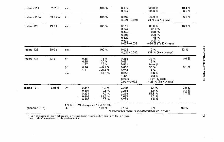
Indiurn-113117 99.5 rnin i.t. 100 % 0.392 64.9 % 35.1 % 0.024 -0.028 24 % (In K X-rays)
0.027-0.032 -86 % (Te K X-rays)
Iodine-1 25 60.0 d ex. 100 % 0.035 7 % 93 % 5; 0.027-0.032 138 % (Te K X-rays) g g
Iodine-l 26 13 d P- 0.38 3 % 0.389 32 % 0.5 % g 0.88 30 % 0.491 2 % N 1.27 15 % 0.51 1 from p+ 0.46 -0.1 % 0.666 30 % 0.1 %
5 P+
1 .l -0.4 % 0.754 4 % e.c. 51.5 % 0.880 0.8 %
B =!
1.420 0.3 % d
others t O . l % each g m 0.027-0.032 -38 % (Te K X-rays)
. . . . . . . . . . . . . . . . . . . . . . . . . . . . . . . . . . . . . . . . . . . . . . . . . . . . . . . . . . . . . . . . . . . . . . . . . . . . . . . . . . 1.3 % of '"1 decays via 12 d 131mXe
(Xenon-1 31 m) i.t. 100 % 0.1 64 2 % 98 % (percentages relate to disintegrations of 31mXe)
a VS = microsecond; ms = millisecond; s = second; min = minute; h = hour; d = day; a = year. e.c. = electron capture; Lt. = isomeric transition.
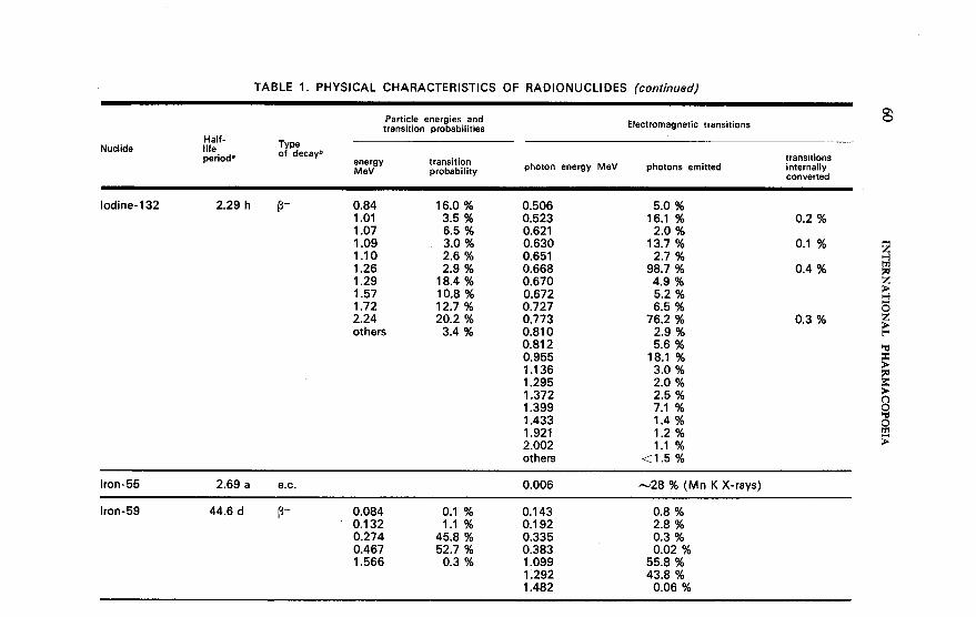
TABLE 1. PHYSICAL CHARACTERISTICS OF RADIONUCLIDES (continued)
Panicle energies and transition probabilities Electromagnetic transitions
3 Half-
Nuclide life Type period. of decayb
energy transition transitions MeV probability photon energy MeV photons emitted internally
converted
Iodine-1 32 2.29 h P- 0.84 1.01 1.07 1.09 1 .l 0 1.26 1.29 1.57 1.72 2.24 others
0.506 0.523 0.621 0.630 0.651 0.668 0.670 0.672 0.727 0.773 0.81 0 0.81 2 0.955 1 .l 36 1.295 1.372 1.399 1.433 1 .g21 2.002 others
- -- - -
Iron-55 2.69 a e.c. 0.006 -28 % (Mn K X-rays)
Iron-59 44.6 d P- 0.084 0.1 % 0.1 43 0.8 % 0.1 32 1.1 % 0.1 92 2.8 % 0.274 45.8 % 0.335 0.3 % 0.467 52.7 % 0.383 0.02 % 1.566 0.3 % 1.099 55.8 %
1.292 43.8 % 1.482 0.06 %

RADIOPHARMACEUTICALS 6 1
: sss : q9C9 . m o o . m r

TABLE 1. PHYSICAL CHARACTERISTICS OF RADIONUCLIDES (continued) m
Particle energies and h,
transition probabilities Electromagnetic transitions
Nuclide Half- life,
Tvne
---.-Am perloo- of decayb energy transition transitions M eV probability photon energy MeV photons emitted internally
converted
0.265 0.280 0.401 others 0.01 0-0.01 2 . . . . . . . . . . . . . . . . via 16.4 ms 75mAs 0.024 0.280 0.304 0.01 0-0.01 2
56.9 % 18.5 % 11.7 %
(0.05 % each -50 % (As K X-rays)
0.03 % 5.4 % 1.2 %
-2.6 % (As K X-rays)
. . . . . . . . . . . . . . . . . . . . . . . . . . . . . . . . . . . . . . . . . . . . . . . . . . . . . . . . . . . . . . . . . . . . . . . . . . . . . . . . . . Daughter 99Tc

100 % 0.255 2.1 % 0.1 % 0.024-0.028 73 % (In K X-rays)
. . . . . . . . . . . . . . . . . . . . . . . . . . . . . . . . . . . . . . . . . . . . . . . . . . . . . . . . . . . . . . . . . . . . . . . . . . . . . . . . . Daughter 1'3mln
Tritium (3H) 12.35 a P- 0.01 86 100 %
100 % 0.1 64 2 % 98 % 0.029-0.035 -52 % (Xe K X-rays)
Xenon-1 33 5.25 d P- 0.266 0.9 % 0.080 0.4 % 0.5 % 0.346 99.1 % 0.081 36.6 % 63.3 % 0
0.1 60 0.05 % ?- 0.030-0.036 -46 % (CS K X-rays) P
Xenon-1 33m 2.26 d i.t. 100 % 0.233 8 % 92 % 0.029-0.035 -59 % (Xe K X-rays) g
. . . . . . . . . . . . . . . . . . . . . . . . . . . . . . . . . . . . . . . . . . . . . . . . . . . . . . . . . . . . . . . . . . . . . . . . . . . . . . . . . . ?- Daughter 133Xe g
a fls = microsecond; ms = millisecond; s = second; min = minute; h = hour; d = day; a = year. e.c. = electron capture; i.t. = isomeric transition.

64 INTERNATIONAL PHARMACOPOEIA
employing liquid or solid phosphors may be used for the measurement of alpha, beta, and gamma emitters. Solid-state devices may also be used for alpha, beta, and gamma measurements. The electronic circuitry associated with a detector system usually consists of a high-voltage supply, an amplifier, a pulse-height selector, and a scaler, a ratemeter, or other readout device. When the electronic scaling device or the scaler in a counting assembly is replaced by an electronic integrating device, the resultant assembly is a ratemeter. Ratemeters are used for the purpose of monitoring and surveying radioactivity and are somewhat less precise as measuring instruments than the counters. Ionization chambers are often used for measuring gamma-ray activities and, provided they are thin-walled, for measuring X-rays.
Radiation from a radioactive source is emitted in all directions. Pro- cedures for the standardization and measurement of such sources by means of a count of the emissions in all directions are known as 4x- counting; those based on a count of the emissions in a solid angle of 2x steradians are known as 2x-counting; and those based on a fraction of the emissions defined by the solid angle subtended from the detector to the source are known as counting in a fixed geometry. It is customary to assay the radioactivity of a preparation by comparison with a standard- ized preparation using identical geometry conditions. The validity of such an assay is critically dependent upon the reproducibility of the spatial relationships of the source to the detector and its surroundings and upon the accuracy of the standardized preparation. In the primary standardization of radionuclides coincidence techniques are employed in preference to simple 4x-counting whenever the decay scheme of the radionuclide permits. One of the most commonly employed coincidence techniques is 4x-betalgamma coincidence counting, which is used for nuclides in which some or all of the disintegrations are followed by prompt photon emission. An additional adjacent detector, sensitive only to photons, is used to measure the efficiency in the 4x-counter of those disintegrations with which the photons are coincident. 4x-Gammalgamma coincidence counting techniques are often employed for the standard- ization of pure gamma emitters.
The construction and performance of instruments and accessory apparatus vary. The preparation of samples must be modified to obtain satisfactory results with a particular instrument. The operator must follow carefully the manufacturer's instructions for optimum instrument performance and substantiate results by careful examination of known samples. Proper instrument functioning and reliability must be monitored on a day-to-day basis through the use of secondary reference prep- arations.
Radioactivity due to materials of construction, to cosmic rays, and to spontaneous discharges in the atmosphere contributes what is known

RADIOPHARMACEUTICALS 65
as the background activity. All sample radioactivity measurements must be corrected by subtracting background activity.
In the counting of samples at high activity levels, corrections must be made also for loss of counts due to inability of the equipment to resolve pulses arriving in close succession. Such coincidence-loss corrections must be made prior to the subtraction of background correction.
The corrected count rate, R, is given by the formula
where r is the observed count rate, and t is the resolving time. A radioactivity count is a statistical value, i.e., it is a measure of
nuclear decay probabilities, and is not exactly constant over any given time interval. The magnitude of the standard deviation is approxi- mately equal to the square root of the number of counts. In general, at least 10 000 counts are necessary to obtain a standard deviation of 1 "/,.
Absorption
Ionizing radiation is absorbed in the material surrounding the source of the radiation. Such absorption occurs in air, in the sample itself (self-absorption), in sample coverings, in the window of the detection device, and in any special absorbers placed between the sample and the detector. Since alpha particles have a short range of penetration in matter, beta particles have a somewhat greater range, and gamma rays are deeply penetrating, identification of the type and energy of radiation emitted from a particular radionuclide may be determined by the use of absorbers of varying thickness. In practice, this method is little used, and then only in connexion with beta emitters. However, variations in counting rate due to variations in thickness and density of sample con- tainers can be a major problem with beta emitters and with X-ray emitters, such a iodine-125. Plastic tubes, in which variations of density and thickness are minimal, are therefore often employed.
The absorption coefficient (p), which is the reciprocal of the "thickness" expressed in mg/cm2, or the half-thickness (the thickness of absorber required to reduce the radioactivity by a factor of two), is commonly determined to characterize the beta radiation emitted by a radionuclide.
Method
The following procedure is used for the identification test in "Natrii Phosphatis (32P) Injectio" for the measurement of beta activity and for calculation of the absorption coefficient of half-thickness:

66 INTERNATIONAL PHARMACOPOEIA
Place the radioactive substance, suitably mounted for counting, under a suitable counter. Make count rate determinations individually and successively, using at least 6 different thicknesses of aluminium foil chosen from a range of 10 to 200 mg/cm2 and a single absorber with a thickness of at least 800 mg/cm2. The sample and absorbers should be as close as possible to the detector in order to minimize scattering effects. Obtain the net beta count rate at the various absorbers used by subtracting the count rate found with the thickest absorber (800 mg/cm2 or more). Plot the logarithm of the net beta count rate as a function of the total absorber thickness. The total absorber thickness is the thickness of the aluminium plus the thickness of the counter window (as stated by the manufacturer), plus the air-equivalent thickness (the distance, expressed in cm, of the sample from the counter window multiplied by 1.205), all expressed in mg/cm2. An approximately straight line results.
Choose two of the absorber thicknesses (t, and t2) that are 20 mg/cm2 or more apart and that fall on the plot, and calculate the absorption coefficient (,U) from the equation
where t, is the thinner absorber, t2 is the thicker absorber, and A,, and A,. represent the net beta count rate with t, and t2 absorbers, respectively. Alternatively the half-thickness may be read directly from the plot.
The choice of absorber thickness depends on the radionuclide. For radionuclides other than phosphorus-32, which have higher or lower beta energy, greater or lesser absorber thicknesses are necessary.
For characterization of the radionuclide, the absorption coefficient or the half-thickness should be within * 5 % of that found for a sample of the same radionuclide of known purity when determined in parallel.
The count rate at zero total absorber thickness may be determined by plotting a curve identical with the one described for determination of the absorption coefficient and extrapolating the straight line plot to zero absorber thickness, taking into consideration the thickness, expressed in mg/cm2, of sample coverings, the air, and the counter window.
Radiation spectrometry
Crystal scintillation spectrometry
When the energy of beta or gamma radiation is dissipated within materials known as scintillators, light is produced in an amount propor- tional to the energy dissipated. This quantity of light may be measured by suitable means, and is proportional to the energy absorbed in the scintillator. The light emitted under the impact of a gamma photon

RADIOPHARMACEUTICALS 67
or a beta particle is converted into an electric output pulse by a photo- multiplier. Scanning of the output pulses with a suitable pulse-height analyser results in an energy spectrum of the source.
The scintillators most commonly used for gamma spectrometry are single crystals of thallium-activated sodium iodide. Gamma-ray scin- tillation spectra show one or more sharp, characteristic photoelectric peaks, corresponding to the energies of the gamma radiation of the source. They are thus useful for identification purposes and also for the detection of gamma-emitting impurities in a preparation. These peaks are accompanied by other peaks due to secondary effects of radiation on the scintillator and its surroundings, such as backscatter, positron annihilation, coincidence summing, and fluorescent X-rays. In addition, broad bands known as the Compton continua arise from the scattering of the gamma photons in the scintillator and in surrounding materials. Calibration of the instrument is achieved with the use of known samples of radionuclides whose energy spectra have been characterized. The shape of the spectrum produced will vary with the instrument used, owing to such factors as differences in the shape and size of the crystal, in the shielding materials used, the distance between the source and the detector, and in the types of discriminator employed in the pulse-height analysers. When using the spectrum for identification of radionuclides it is therefore necessary to compare the spectrum with that of a known sample of the radionuclide obtained in the same instrument under identical conditions.
Certain radionuclides, for example, iodine-125, emit characteristic X-rays of well-defined energies that will produce photoelectric peaks in a suitable gamma spectrometer. Beta radiation also interacts with the scintillators, but the spectra are continuous and diffuse and generally of no use for identification of the radionuclide or for the detection of beta- emitting impurities in a preparation.
Semiconductor detector spectrometry
Gamma-ray and beta-particle spectra may be obtained using solid- state detectors. The peaks obtained do not suffer to the same extent the broadening shown in crystal scintillation spectrometry, and the resolution of gamma photons of similar energies is very much improved. However, the efficiencies of such detectors are much lower.
The energy required to create an electron-hole pair or to promote an electron from the valence band to the conduction band in a semi- conductor is far less than the energy required to produce a photon in a scintillation crystal. In gamma-ray spectrometry a lithium-drifted germanium detector can provide an energy resolution of 0.33 % for the 1.33 MeV photon of cobalt-60, as compared with 5.9 % with a 7.6-cm X 7.6-cm thallium-activated sodium iodide crystal.

68 INTERNATIONAL PHARMACOPOEIA
Liquid scintillation counting
For weak beta-emitters like 35S, 14C and 3H, where self-absorption of the low-energy beta particles is significant, the preferred counting method is by liquid scintillation, which can occasionally be employed also for emitters of X-rays, alpha-particles, and gamma-rays. If the sample to be counted is dissolved in, or mixed with, a solution of an appropriate scintillator material, the decay energy from the sample is converted into light photons. These are sensed by a photomultiplier, which converts them into an electric pulse, whose intensity is proportional to the energy of the initial radiation. Thus, simultaneous counting of several radionuclides differing in the energy of emitted radiation can be effected with suitable discriminators (pulse-height analysers), providing the energy separation is sufficient. Detection efficiencies approaching 95 % for 14C and 60 % for 3H are reached because self-absorption is minimized.
The scintillator solute usually consists of a polycyclic aromatic com- pound, such as p-terphenyl or 2,5-diphenyloxazole (primary solute), together with a secondary solute, such as 1,4-di[2-(4-methyl-5-phenyloxa- zo1e)lbenzene (Dimethyl-POPOP), that shifts the wavelength of the light emitted to match the highest sensitivity of the photomultiplier tube. Water-immiscible solvents, such as toluene, or water-miscible solvents, such as dioxan, can be used. To facilitate the counting of aqueous solutions, special solvents have been developed. Alternatively, samples may be counted as suspensions in scintillator gels. As a means of attaining compatibility and miscibility with aqueous specimens to be assayed, many additives, such as surfactants and solubilizing agents, are also incorporated into the scintillator. For accurate determination of sample radioactivity, care must be exercised to prepare a sample that is truly homogeneous. The presence of impurities and colour in the solution causes a decrease in the number and energy of photons reaching the photomultiplier tube; such a decrease is known as quenching. Accu- rate radioactivity measurement requires correcting for count-rate loss due to quenching. Solutions containing organic scintillators are prone to photo-excitation and samples may need to be prepared in subdued light and kept in darkness before counting.
Radiation Shielding
Adequate shielding must be used to protect laboratory personnel from ionizing radiation, and measuring instruments must be suitably shielded from background radiation.

RADIOPHARMACEUTICALS 69
Alpha and beta radiations are readily shielded because of their limited range of penetration, although the production of Bremsstrahlung by the latter must be taken into account (see below). The range of alpha and beta particles varies inherently with their kinetic energy. The alpha particles are monoenergetic and have a range of a few centimetres in air. The absorption of beta particles, owing to their continuous energy spect- rum and scattering, follows an approximately exponential function. The range of beta particles in air varies from centimetres to metres.
The secondary radiation produced by beta radiation upon absorption by shielding materials is known as Bremsstrahlung and resembles soft X-rays in its property of penetration. The higher the atomic number or density of the absorbing material, the greater the intensity of he Brems- strahlung produced. Elements of low atomic number produce low- energy Bremsstrahlung, which is readily absorbed; therefore, materials of low atomic number or of low density, such as aluminium, glass, or transparent plastic, are used to shield sources of beta radiation.
Gamma-ray radiation is deeply penetrating. Attenuation of gamma- ray radiation in matter is exponential and is given in terms of half-value layers. The half-value layer is the thickness of shielding material necessary to decrease the intensity of radiation to half its initial value. A shield of 7 half-value layers is of a thickness that will reduce the intensity of radiation to less than 1 % of its unshielded intensity of activity. Gamma- ray radiation is commonly shielded with lead.
Intensity of gamma-ray radiation is diminished according to the inverse square of the intervening distance between the source and the point of reference. Radioactive materials of multimillicurie strength can be handled safely in the laboratory by using proper shielding and/or by arranging for the maximum practicable distance between the source and the operator by means of remote-handling devices.
Determination of Radionuclidic Purity
For gamma emitters the most useful method of examination for radionuclidic purity is gamma spectrometry. It is not, however, a com- pletely certain method, because:
(a) beta-emitting impurities are, in general, not detected; (b) when sodium iodide detectors are employed, the photoelectric
peaks due to impurities may be obscured by those due to the major radionuclide, or, in other words, the degree of resolution of the instrument is insufficient; this problem can be overcome through the use of high resolution solid state semiconductor detectors, such as a lithium-drifted germanium (Ge :Li) detector;

70 INTERNATIONAL PHARMACOPOEIA
(c) unless the instrument has been calibrated with a standard source of known radionuclidic purity under identical conditions of geometry, it is difficult to determine whether additional peaks are due to impurities or whether they result from such secondary effects as backscatter, coinci- dence summation, or fluorescent X-rays.
The range of gamma spectrometry may be extended in two ways: first, by observing changes in the spectrum of a preparation with time (this is especially useful in detecting the presence of long-lived impurities in a preparation of a short-lived radionuclide); secondly, by the use of chemical separations, whereby the major radionuclide may be removed by chemical means and the residue examined for impurities, or whereby specific impurities may be separated chemically and then quantified. It is evident that chemical means will not separate an impurity that is isotopic with the major radionuclide.
Requirements for radionuclidic purity
Requirements for radionuclidic purity are specified in two ways:
1. By expression of a minimum level of radionuclidic purity. Unless otherwise stated in the individual monograph, the gamma-ray spectrum, as determined by simple gamma spectrometry employing a sodium iodide detector, should not be significantly different from that of a standardized solution of the radionuclide before the expiry date is reached. As discussed above, it is difficult to set more precise requirements for a minimum level of radionuclidic purity.
2. By expression of maximum levels of specific radionuclidic impurities in the individual monographs. In general, such impurities are those that are known to be likely to arise during the production of the material - for example, mercury-203 in a preparation of mercury-197.
It is evident that while the above requirements are necessary, they are not in themselves sufficient to ensure that the radionuclidic purity of a preparation is sufficient for human use. A duty must remain with the manufacturer to examine his products in detail, and especially to examine preparations of short-lived radionuclides for long-lived impurities after a suitable period of decay. In this way, the manufacturer may satisfy himself that the manufacturing processes employed are producing materials of appropriate purity. In particular, the radionuclidic composi- tion of certain preparations is determined by the chemical and isotopic composition of the target material, which is irradiated with neutrons, and trial preparations are advisable when new batches of target material are employed.

RADIOPHARMACEUTICALS 71
Determination of Radiochemical Purity
Radiochemical purity can be studied by a variety of techniques, but paper chromatography and thin-layer chromatography (see pp. 80- 84) are of particular importance. After completion of the separation, the distribution of radioactivity on the chromatogram is determined. The weight of substance applied to the chromatogram is often extremely small (because of the great sensitivity of detection of the radioactivity) and particular care has to be taken in interpretation with regard to the formation of artefacts. Instead of chromatography, electrophoresis may be used for separation (see pp. 98-102). As mentioned above, the addition of carriers (i.e., the corresponding non-radioactive compounds) for both the radiopharmaceutical itself and the suspected impurities is sometimes helpful. There is, however, a danger that when an inactive carrier of the radiopharmaceutical is added it may interact with the radiochemical impurity, leading to underestimation of these impurities. Another useful technique involves monitoring the biological distribution of the injected radiopharmaceutical in suitable test animals.
Determination of Chemical Purity
Chemical purity refers to the proportion of the preparation that is in the specified chemical form regardless of the presence of radioactivity; it may be determined by normal methods of analysis.
The chemical purity of a preparation is often no guide to its radio- chemical purity. Preparations, especially those resulting from exchange reactions (for example, a preparation of o-iodohippuric acid in which some of the iodine atoms are replaced by atoms of iodine-131), may be of high chemical purity but may contain impurities of high specific activity (that is, a tiny weight of an impurity may be associated with a relatively large amount of the radionuclide).
In general, chemical impurities in preparations of radiopharmaceuticals are objectionable only if they are toxic or if they modify the physiological processes that are under study.
Tests for Sterility and Pyrogens
A number of monographs for radiopharmaceuticals contain the requirement that the product be sterile and free of pyrogens. The half- life of radiopharmaceutical products is such that, as a rule only tests for

72 INTERNATIONAL PHARMACOPOEIA
pyrogens can be completed prior to release. Tests for sterility must, in general, be completed retrospectively.
Sterility tests
The manufacturer should begin the sterility test as soon as possible and read the results after release.
A particular responsibility falls upon the manufacturer of radio- pharmaceuticals to validate the sterilization process by all suitable measures, which may include careful and frequent calibration of sterilizers and the use of biological and chemical indicators of the efficiency of the sterilization process.
Pyrogen tests
The manufacturer also bears a particular responsibility to ensure that all substances used in the preparation of radiopharmaceuticals are handled in a manner that ensures their freedom from pyrogens. Pyrogen tests are specified in certain monographs where there are special dangers (see also pp. 155-156).
Addition of Bacteriostatic Agents
Injections of radiopharmaceuticals are commonly supplied in con- tainers that are sealed to permit the withdrawal of successive doses on different occasions. The International Pharmacopoeia normally requires that such injections should contain a suitable bacteriostatic agent in a suitable concentration.
Many common bacteriostatic agents (for example, benzyl alcohol) are gradually destroyed by the effect of radiation in aqueous solutions. The rate of destruction is dependent upon a number of factors, including the nature of the radionuclide and the radioactive concentration of the solution. It is therefore not always possible to prescribe an effective bacteriostatic agent for an injection of a radiopharmaceutical and for certain preparations the addition of an agent is undesirable; for this reason the inclusion of bacteriostatic agents is not mandatory. The nature of the bacteriostatic agent, if present, must be stated on the label; if no bacteriostatic agent is present, this must also be stated. Radio- pharmaceuticals whose expiry periods are greater than one day and that do not contain a bacteriostatic agent should preferably be supplied in single-dose containers.

RADIOPHARMACEUTICALS
Other Requirements
Radiopharmaceuticals administered parenterally should comply with the relevant requirements for injections in the International Pharmaco- poeia, except that they are not subject to the requirements concerning volume of injection in a single-dose container.
Expiry Date
The special nature of a radiopharmaceutical requires that it be assigned an expiry period (or an expiry date), beyond which its continued use is not recommended. The expiry period so designated begins with the date at which the radioactivity is expressed on the label, and may be stated in terms of days, weeks or months. For longer-lived radionuclides, the expiry period does not exceed 6 months. The expiry period depends on the radiochemical stability and the content of longer-lived radio- nuclidic impurity in the preparation under consideration. At the end of the expiry period, the radioactivity will have decreased to the extent where insufficient radioactivity remains to serve the intended purpose or where the dose of active ingredient must be increased so much that undesirable physiological responses occur. In addition, chemical or radiation decom- position may have reduced the radiochemical purity to an unacceptable extent. Also the radionuclidic impurity content may be such that an unacceptable radiation dose would be delivered to the patient. The use of products beyond their expiry periods is therefore inadvisable.
Labelling
In general, the following information should appear on the immediate container (for example, vial) :
(1) the name of the preparation;
(2) a statement that the product is radioactive;
(3) the name and location of the manufacturer;
(4) the total radioactivity present at a stated date and hour (whenever the half-life period is more than 30 days only the date need be stated);
(5) the expiry date or the expiry period;
(6) a number or other indication by which the history of the product may be traced (for example, batch or lot number);

74 INTERNATIONAL PHARMACOPOEIA
(7) in the case of solutions, the total volume of the solution;
(8) special storage requirements with respect to temperature and light.
NOTE : In the case of a solution, instead of a statement of the total radioactivity, a statement of the radioactive concentration (for example, in mCi or MBq per ml of the solution) may be given.
The shipment of radioactive substances is subject to special national and international regulations as regards their packaging and outer labelling.
Storage
Radiopharmaceuticals should be kept in well-closed containers and stored in an area assigned for the purpose. The storage conditions should be such that the maximum radiation dose rate to which persons may be exposed is reduced to an acceptable level. Care should be taken to comply with national regulations for protection against ionizing radiation. Glass containers may darken under the effect of radiation.
POWDER FINENESS AND SIEVES
A. Powders
The degree of coarseness or fineness of a powder is differentiated by the nominal aperture size of the mesh of the sieve through which the powder is able to pass, expressed in pm.
The following terms are used in the description of powders:
Coarse powder (2000/355). A powder of which all the particles pass through a No. 2000 sieve, and not more than 40 % through a No. 355 sieve.
Moderately coarse powder (71012.50). A powder of which all the particles pass through a No. 710 sieve, and not more than 40 % through a No. 250 sieve.
Moderately fine powder (3551180). . A powder of which all the par- ticles pass through a No. 355 sieve, and not more than 40 % through a No. 180 sieve.
Fine powder (180). A powder of which all the particles pass through a No. 180 sieve.
Very fine powder (125). A powder of which all the particles pass through a No. 125 sieve.

POWDER FINENESS, SIEVES 75
When the fineness of a powder is described by means of a number, it is intended that all the particles of the powder should pass through the sieve distinguished by that number.
B. Sieves
The wire sieves used in sifting powdered drugs are distinguished by numbers, which indicate the nominal aperture size expressed in pm.
The sieves are made of wires of uniform circular cross-section, in accordance with the specifications given in Table 2.
TABLE 2. WIRE MESH SIEVES
Number of sieve Nominal size Nominal diameter Approximate
(rrm) of aperture of wire screening area
(mm) (mm) (%)
The nominal size of aperture of wire mesh sieves has been selected principally from among those recommended in the IS0 standard 565-1972.
