the internet of things
TRANSCRIPT

THE INTERNETOF THINGS

AUERBACH PUBLICATIONS
Unlicensed Mobile Access Technology: Protocols, Architectures,Security, Standards and Applications
Wireless Quality-of-Service: Techniques, Standards and Applications
Broadband Mobile Multimedia: Techniques and Applications
The Internet of Things: From RFID to the Next-Generation PervasiveNetworked Systems
Millimeter Wave Technology in Wireless PAN, LAN, and MAN
Security in Wireless Mesh Networks
Resource, Mobility and Security Management in Wireless Networks andMobile Communications
Wireless Mesh Networking: Architectures, Protocols and Standards
Mobile WIMAX: Toward Broadband Wireless Metropolitan Area Networks
Distributed Antenna Systems: Open Architecture for FutureWireless Communications
WIRELESS NETWORKSAND MOBILE COMMUNICATIONS
New York London
THE INTERNETOF THINGS
From RFID to the Next-GenerationPervasive Networked Systems
Edited by
Lu Yan s Yan ZhangLaurence T. Yang s Huansheng Ning

Auerbach PublicationsTaylor & Francis Group6000 Broken Sound Parkway NW, Suite 300Boca Raton, FL 33487-2742
© 2008 by Taylor & Francis Group, LLC
Auerbach is an imprint of Taylor & Francis Group, an Informa business
No claim to original U.S. Government works
Printed in the United States of America on acid-free paper
10 9 8 7 6 5 4 3 2 1
International Standard Book Number-13: 978-1-4200-5281-7 (Hardcover)
This book contains information obtained from authentic and highly regarded sources Reason-
able efforts have been made to publish reliable data and information, but the author and publisher
cannot assume responsibility for the validity of all materials or the consequences of their use. The
Authors and Publishers have attempted to trace the copyright holders of all material reproduced
in this publication and apologize to copyright holders if permission to publish in this form has not
been obtained. If any copyright material has not been acknowledged please write and let us know so
we may rectify in any future reprint
Except as permitted under U.S. Copyright Law, no part of this book may be reprinted, reproduced,
transmitted, or utilized in any form by any electronic, mechanical, or other means, now known or
hereafter invented, including photocopying, microfilming, and recording, or in any information
storage or retrieval system, without written permission from the publishers.
For permission to photocopy or use material electronically from this work, please access www.
copyright.com (http://www.copyright.com/) or contact the Copyright Clearance Center, Inc. (CCC)
222 Rosewood Drive, Danvers, MA 01923, 978-750-8400. CCC is a not-for-profit organization that
provides licenses and registration for a variety of users. For organizations that have been granted a
photocopy license by the CCC, a separate system of payment has been arranged.
Trademark Notice: Product or corporate names may be trademarks or registered trademarks, and
are used only for identification and explanation without intent to infringe.
Library of Congress Cataloging-in-Publication Data
The Internet of things : from RFID to the next-generation pervasive networked systems / Lu Yan ... [et al.].
p. cm. -- (Wireless networks and mobile communications ; 8)Includes bibliographical references and index.
ISBN 978-1-4200-5281-7 (alk. paper)1. Ubiquitous computing. 2. Radio frequency identification systems. 3.
Wireless communication systems. I. Yan, Lu. II. Title. III. Series.
QA76.5915.I68 2008
384.5--dc22 2007047411
Visit the Taylor & Francis Web site at
http://www.taylorandfrancis.com
and the Auerbach Web site at
http://www.auerbach-publications.com

v
Contents
1 RFID Tags ..............................................................................................1PETER J. HAWRYLAK, M.H. MICKLE, AND J.T. CAIN
2 RFID Automatic Identification and Data Capture ..............................33XIAOYONG SU, CHICHENG CHU, B.S. PRABHU,AND RAJIT GADH
3 RFID Data Warehousing and Analysis ................................................53HECTOR GONZALEZ AND JIAWEI HAN
4 RFID Data Management: Issues, Solutions,and Directions......................................................................................81QUAN Z. SHENG, KERRY L. TAYLOR, ZAKARIA MAAMAR,
AND PAUL BREBNER
5 RFID Security: Threats and Solutions ...............................................107NICOLAS SKLAVOS AND VISHAL AGARWAL
6 RFID Specification Revisited.................................................................127PEDRO PERISLOPEZ, JULIO C. HERNANDEZCASTRO,JUAN M. ESTEVEZTAPIADOR, AND ARTURO RIBAGORDA
vi Contents
7 RFIG Geometric Context of Wirless Tags..........................................157RAMESH RASKAR, PAUL BEARDSLEY, PAUL DIETZ,AND JEROEN VAN BAAR
8 RFID Application in Animal Monitoring..........................................165VASILEIOS NTAFIS, CHARALAMPOS Z. PATRIKAKIS, EIRINI G.FRAGKIADAKI, AND EFTYCHIA M. XYLOURIFRAGKIADAKI
9 RFID Applications in Assets and Vehicles Tracking..........................185WEI LIU, ZHAO PENG, WENQUING CHENG,JIANHUA HE, AND YAN ZHANG
10 RFID Enabled logistics Services ....................................................... 207ZONGWEI LUO, EDWARD C. WONG, C.J. TAN, S.J. ZHOU,WILLIAM CHEUNG, AND JIMING LIU
11 Location Tracking in an Office Environment: The NationwideCase Study..........................................................................................233IRENE LOPEZ DE VALLEJO, STEPHEN HAILES,RUTH CONROYDALTON, AND ALAN PENN
12 Pervasive Computing Security: Bluetooth® Example .........................257GIORGOS KOSTOPOULOS, PARIS KITSOS,AND ODYSSEAS KOUFOPAVLOU
13 Internet of Things: A Context-Awareness Perspective ........................287DAVY PREUVENEERS AND YOLANDE BERBERS
Index...................................................................................... 309
vii
Preface
With more than two billion terminals in commercial operation world-wide, wire-less and mobile technologies have enabled a first wave of pervasive communication systems and applications. Still, this is only the beginning as wireless technologies such as RFID are currently contemplated with a deployment potential of tens of billions of tags and a virtually unlimited application potential. A recent ITU report depicts a scenario of “Internet of things” — a world in which billions of objects will report their location, identity, and history over wireless connections.
The realization of the “Internet of things” will probably require dramatic changes in systems, architectures and communications which should be flexible, adaptive, secure, and pervasive without being intrusive. Although the RFID tech-nology has already laid a foundation for the “Internet of things,” other research and development thrusts are also required to enable such a pervasive networking world, such as communications protocols, middleware, applications support, MAC, data processing, semantic computing and search capabilities, and even low-power technologies.
Significant R&D work has been undertaken over recent years on these systems, with pioneering work initiated in the US. In Europe, the European Union has been instrumental in supporting the many R&D facets of pervasive communications. Asia is also proactively moving into this field through various R&D initiatives on “ubiquitous communications.” Emerging industrial interest in this field indicates that prospects for commercial applications of these technologies, are promising, and it is our hypothesis that a generic and comprehensive textbook is needed, where system-level problems in the context of the “Internet of things” are indicated and tutorials on their applications are required.
While placed in the specific context of the exciting expansion period of this research direction, this book will provide readers a comprehensive technical, prac-tical, deploying, policy guidance covering fundamentals and recent advances in pervasive networked systems, from RFID towards “Internet of things.”
viii Preface
The main features of this book include:
The first book of its kinds to address the major new technological develop-ments in the field “Internet of things”Reflects current research trends as well as industry needsA good balance between theoretical issues and practical issuesCovers case studies, experience reports, and best practiceConcept and technical issues addressed in this book are timely, and being seriously considered in the technology roadmap and strategies in EU, US, and Asia
This book serves well as a useful reference for students, educators, faculties, telecom service providers, research strategists, scientists, researchers, and engineers in the field of wireless networks and mobile communications.
We would like to acknowledge the effort and time invested by all contributors for their excellent work. All of them are extremely professional and cooperative. Our thanks also go to the anonymous chapter reviewers, who have provided invalu-able comments and suggestions which help to significantly improve the whole text. Special thanks go to Richard O’Hanley, Jessica Vakili and Jay Margolis of Taylor & Francis Group for their support, patience and professionalism given in the whole publication process of this book. Last but not least, special thanks should also go to our families and friends for their constant encouragement, patience and under-standing throughout this book project.
Lu Yan, Yan Zhang, Laurence T. Yang, Huansheng Ning

ix
Contributors
Vishal AgarwalIndian Institute of TechnologyElectrical Engineering DepartmentBombay, India
Paul BeardsleyMitsubishi Electric Research LabsCambridge, MA, U.S.A.
Yolande BerbersKatholieke Universiteit LeuvenDepartement of Computer Science Leuven, Belgium
Paul BrebnerNational ICT Australia LimitedBraddon, Australia
J.T. CainUniversity of PittsburghPittsburgh, PA, U.S.A.
Wenqing ChengHuazhong University of Science
and TechnologyWuhan, China
William CheungUniversity of Hong KongE-business Technology InstituteHong Kong, China
Chi-Cheng ChuUniversity of California, Los AngelesWINMECLos Angeles, CA, U.S.A.
Ruth Conroy-DaltonUniversity College LondonThe Bartlett London, UK
Paul DietzMitsubishi Electric Research LabsCambridge, MA, U.S.A.
Juan M. Estevez-TapiadorCarlos III University of MadridComputer Science DepartmentMadrid, Spain
Eirini G. FragkiadakiAgricultural University of AthensFaculty of Animal Science
and AquacultureAthens, Greece
Rajit GadhUniversity of California, Los AngelesWINMECLos Angeles, CA, U.S.A.

x Contributors
Hector GonzalezUniversity of Illinois at
Urbana-ChampaignDepartment of Computer ScienceUrbana, IL, U.S.A.
Stephen HailesUniversity College LondonDepartment of Computer ScienceLondon, UK
Jiawei HanUniversity of Illinois at
Urbana-ChampaignDepartment of Computer ScienceUrbana, IL, U.S.A.
Peter J. HawrylakUniversity of PittsburghPittsburgh, PA, U.S.A.
Jianhua HeHuazhong University of Science
and TechnologyWuhan, China
Julio C. Hernandez-CastroCarlos III University of MadridComputer Science DepartmentMadrid, Spain
Paris KitsosHellenic Open University School of Science and Technology Patras, Greece
Giorgos KostopoulosUniversity of PatrasDepartment of Electrical and
Computer EngineeringPatras, Greece
Odysseas KoufopavlouUniversity of PatrasDepartment of Electrical and
Computer EngineeringPatras, Greece
Jiming LiuUniversity of Hong KongE-business Technology InstituteHong Kong, China
Wei LiuHuazhong University of Science
and TechnologyWuhan, China
Irene Lopez de VallejoUniversity College LondonThe Bartlett London, UK
Zongwei LuoUniversity of Hong KongE-business Technology InstituteHong Kong, China
Zakaria MaamarZayed UniversityCollege of Information TechnologyDubai, U.A.E.
M.H. MickleUniversity of PittsburghPittsburgh, PA, U.S.A.
Vasileios A. NtafisAgricultural University of AthensFaculty of Animal Science
and AquacultureAthens, Greece
Charalampos Z. PatrikakisNational Technical University
of Athens Department of Electrical Engineering
and Computer Science Athens, Greece
Zhao PengHuazhong University of Science
and TechnologyWuhan, China
Contributors xi
Alan PennUniversity College LondonThe Bartlett London, UK
Pedro Peris-LopezCarlos III University of MadridComputer Science DepartmentMadrid, Spain
B.S. PrabhuUniversity of California, Los AngelesWINMECLos Angeles, CA, U.S.A.
Davy PreuveneersKatholieke Universiteit LeuvenDepartement of Computer Science Heverlee, Belgium
Ramesh RaskarMitsubishi Electric Research LabsCambridge, MA, U.S.A.
Arturo RibagordaCarlos III University of MadridComputer Science DepartmentMadrid, Spain
Quan Z. ShengUniversity of AdelaideSchool of Computer ScienceAdelaide, Australia
Nicolas SklavosUniversity of PatrasPatras, Greece
Xiaoyong SuUniversity of California, Los AngelesWINMECLos Angeles, CA, U.S.A.
C.J. TanUniversity of Hong KongE-business Technology InstituteHong Kong, China
Kerry L. TaylorCommonwealth Scientific and
Industrial Research OrganisationInformation Engineering LaboratoryCanberra, Australia
Jeroen van BaarMitsubishi Electric Research LabsCambridge, MA, U.S.A.
Edward C. WongUniversity of Hong KongE-business Technology InstituteHong Kong, China
Eftychia M. Xylouri-FragkiadakiAgricultural University of Athens Faculty of Animal Science
and AquacultureAthens, Greece
Yan ZhangSimula Research LaboratoryLysaker, Norway
S.J. ZhouUniversity of Hong KongE-business Technology InstituteHong Kong, China


1
Chapter 1
RFID Tags
Peter J. Hawrylak, M.H. Mickle, and J.T. Cain
Contents1.1 Introduction ................................................................................................2
1.1.1 RFID Basics .....................................................................................61.1.2 Passive RFID Tag Basics...................................................................61.1.3 Active RFID Tag Basics....................................................................71.1.4 Semipassive RFID Tag Basics ...........................................................71.1.5 Semiactive RFID Tag Basics.............................................................8
1.2 Passive Tags .................................................................................................81.2.1 How Backscatter Communication Works.........................................81.2.2 Operating Frequencies: An Overview ...............................................91.2.3 Magnetic Coupling: Near-Field ......................................................111.2.4 Electromagnetic Coupling: Far-Field ..............................................121.2.5 Near-Field and Far-Field: Some Key Points.....................................121.2.6 Manufacturing Issues with Passive RFID Tags ...............................151.2.7 The EPC Gen-2 Protocol ................................................................171.2.8 Current Outstanding Issues with Passive RFID Tags .....................19
1.2.8.1 Reducing Tag Size ............................................................191.2.8.2 Lowering Tag Cost ...........................................................191.2.8.3 Increasing Read Range .....................................................191.2.8.4 Increasing Read Rate ........................................................201.2.8.5 Improving Tag Security ....................................................20
1.3 Active Tags ................................................................................................211.3.1 Active Communication Versus Backscatter Communication..........211.3.2 Active Tags Conforming ISO 18000-7 ...........................................21
2 The Internet of Things
Radio Frequency IDentification (RFID) has a long history and is part of the tech-nological revolution both current and past. RFID enables quick payment of tollsand quick identification of items. In addition, RFID provides benefits, such astracking assets, monitoring conditions for safety, and helping to prevent counter-feiting. RFID plays an integral part in the technological revolution along with theInternet and mobile devices, which are connecting the world together. This chapterfocuses on the RFID tag and provides an overview and history of the various typesof tags, their uses, and the physics behind their operation.
1.1 IntroductionRFID has a long history. RFID uses radio waves, which are one form of electro-magnetic waves. As such, the genesis of RFID must be attributed to the founders ofthe electromagnetic wave theory: Michael Faraday, James Maxwell, and HeinrichHertz. In the mid-nineteenth century, Faraday discovered that a current flowingthrough a wire created a magnetic field and conversely that, when a wire is exposedto a magnetic field, a current is present in the wire. Today this discovery is knownas Faraday’s law and along with the Ampere–Maxwell law forms the basis for amagnetic field, or near-field RFID systems. Maxwell developed the mathematicaltheory describing electromagnetism using the work of Faraday and others. Max-well’s work dealt only with the visible, infrared, and ultraviolet bands of the elec-tromagnetic spectrum because the other types of electromagnetic waves were notknown to exist [1]. Hertz was able to verify Maxwell’s work and discovered radiowaves [1], [2]. Today, the existence of numerous other electromagnetic (EM) waves,such as x-rays and gamma rays are known.
1.3.3 Sensors............................................................................................241.3.4 Security...........................................................................................251.3.5 Increasing Battery Life....................................................................261.3.6 Current Outstanding Problems with Active RFID Tags .................27
1.3.6.1 Low Power Communication .............................................271.3.6.2 Lowering Energy Consumption When Dormant .............271.3.6.3 Enhanced Security............................................................28
1.4 Semipassive RFID Tags .............................................................................281.4.1 Extending Read Range ...................................................................281.4.2 Equipping with Sensors ..................................................................291.4.3 Outstanding Issues with Semipassive Tags......................................29
1.4.3.1 Cost..................................................................................291.4.3.2 Lower Power Sensors ........................................................301.4.3.3 Passive Operation as a Fallback.........................................30
1.5 Future of RFID .........................................................................................30References ...........................................................................................................32

RFID Tags 3
From these beginnings, scientists and inventors, such as Reqinald Fessendenand Guglielmo Marconi began in the early part of the twentieth century to developmany radio-based applications we use each day. By the 1930s, crystal radio setsbecame common place in the home allowing people to listen to music from far awaycities and keep track of the local news and sporting events in real-time. FranklinD. Roosevelt was one of the first politicians to use the radio to further his politicalcareer, being elected President of the United States for four consecutive terms. Thecrystal radio with a headset instead of a free-standing speaker did not need electric-ity from the home to operate. The radio wave provided enough energy to move thediaphragm in the headset to reproduce the sound represented by the radio signal,although the listener needed to wear the headset to hear the radio broadcast. Aselectricity was not widely available outside of major cities in the 1930s, the crystalset was an important achievement. The ability of the crystal set to harvest energyfrom a radio signal is one of the key foundations of the passive RFID technologyemployed and being developed today.
The development of the radio also led to the development of Radio DetectionAnd Ranging or radar. Radar utilizes the fact that radio waves reflect off an objectenabling their range, height, and bearing to be determined. The militaries of thevarious world powers were all racing to develop radar technology in the years beforeand during World War II. Radar was employed to great effect by the British dur-ing the Battle of Britain. As World War II progressed, the British and the UnitedStates developed methods to reduce the size of the radar sets allowing them tobe mounted in airplanes. Further, the minimum size of the target that could bedetected by the radar set was reduced. Both advancements were key to findingand destroying German U-boats (submarines) to safeguard Allied shipping duringthe Battle of the Atlantic. Without radar and its advancements, the RFID systemsusing the far-field system would likely not exist today.
Another advancement in radio communications is the airplane transponder andits military counterpart, the Identify Friend or Foe (IFF) systems. These systemscommunicate with base stations, such as observation points or airplane controltowers, to provide real-time monitoring and identification of airplanes. IFF sys-tems are used by the military to distinguish between friendly and hostile forces toprevent friendly fire casualties and can be classified as active RFID systems. Today,active RFID systems are employed in similar applications and areas.
As with other electronic devices, advancements in integrated circuit (IC) fab-rication were critical to the development of RFID. The first computers, made ofvacuum tubes, encompassed entire rooms. Today with the advancement in IC fab-rication, computers many times more powerful can be fit into a small device, suchas a cell phone or a Personal Data Assistant (PDA).
The same advancements are true for RFID tags. Most RFID tags have an iden-tifier, which must be stored in nonvolatile memory to retain the identity informa-tion of the tag when the tag is not powered. This is important in passive RFID tagsas most of the time the tag is not powered. The digital component of a RFID tag

4 The Internet of Things
made from vacuum tubes would be too large to be attached to anything but thelargest assets, such as planes, trains, or cars. With the IC revolution, it was possibleto shrink the size of the digital components. Current IC technology enables digitaland analog components to be contained in the same physical chip (die). Today thedigital components and the analog circuitry of a RFID chip are contained in asquare chip no more than 1 mm on a side. The antenna is, by far, the largest part ofa RFID tag today. Without the IC revolution, applying RFID tags to pallets, cases,and items would be unlikely if not impossible.
Equally important to the reduction of size is the reduction in the energy neededfor an IC to operate. As passive RFID devices must harvest energy from the signaltransmitted by the interrogator to operate, this reduction in size is critical. In thepast 10 to 20 years, advancements in IC design and fabrication have allowed lowpower IC chips for RFID tags to be efficiently manufactured. Because the maxi-mum theoretical power that can be harvested is inversely proportional to the dis-tance between the interrogator and the tag, lowering the amount of energy requiredfor IC operation increases range. Range is one critical metric for RFID systemsespecially in the supply chain where the goal is to read all tags on a pallet. Withoutsufficient range those tags in the center of the pallet may not be read.
Tracking animals was one of the earliest applications of RFID [2]. Probably themost wide spread use of a RFID system is the electronic article surveillance (EAS)tags. EAS tags are affixed to items in a store that cause an alarm to go off if custom-ers enter or leave the store when the tags are in the active state. The EAS tags aredeactivated during checkout and are designed to prevent theft of store merchan-dise. Checkpoint and Sensormatic, two leading manufacturers of EAS tags, werecreated in the 1960s [2].
Automatic toll payment is another early application of RFID. The key advancementin automatic toll payment was the common interface of the E-Z Pass system where userscould use the same tag to pay tolls on transportation systems (roads, tunnels, and bridges)operated by different transit authorities. This compatibility was crucial, especially in themid-Atlantic area of the eastern United States where a person traveling from WashingtonD.C. to New York City may need to pay three or more tolls with each toll going to dif-ferent transit authorities. The compatibility of the E-Z Pass system can be compared tothe compatibility of credit card payment machines that allow customers to use any majorcredit card. The E-Z pass system contributed two advancements to RFID: the need forcompatible systems and the ability to read a moving E-Z Pass tag. These advancementsare critical foundations for the electronic product code (EPC) RFID protocols. Read-ing of a moving tag is critical because most distribution centers that service retailers useconveyor belt systems to move and sort items. Reading these items as they move is muchmore efficient and profitable than periodically stopping the conveyors to read the RFIDtags affixed to the items.
RFID is a method to transmit information without a direct hardware con-nection and without a line of sight between the two parties. Because of the lackof the need for a direct connection or a line of sight, RFID is often touted as a

RFID Tags 5
replacement for the barcode. The lack of a line of sight requirement means that a RFIDsystem could take an inventory of an entire pallet simply by passing the pallet through aset of RFID interrogators. A barcode system could perform the same task provided thatthe barcodes on all products in the pallet are facing outward. This solution has significantlimitations as typical item sizes are often too small to allow the barcodes on all items toface the outside of the pallet without leaving unused space in the middle of the pallet.RFID has another advantage over the barcode in that data can be written to RFID tagsonce deployed. Similar barcode technology exists in second dimensional (2D) barcodes,or data matrices, but this technology requires a barcode printer to print each additionalpiece of information. This is expensive, time consuming, and requires a very large areafor the 2D barcode if a large amount of information is going to be stored in 2D mode.With a 2D barcode, the amount of data stored in the barcode is proportional to the areaof the 2D barcode. RFID tags can contain a large amount of memory in a small physicalarea. The primary roadblock to storing huge amounts of data in a RFID tag is in harvest-ing enough energy to power the memory. Adding memory requires more energy for thetag to operate, reducing either read range or tag lifetime.
Most publications concerning RFID in the popular media are about RFID as areplacement of or an improvement over the barcode. This is the initial goal of manymajor retailers, such as Wal-Mart and Metro. While the RFID tag offers manyimprovements over the barcode, a number of major roadblocks still exist beforeRFID tags can be placed on the majority of individual items. Of primary concernis the cost of a single RFID tag and the ability to be 100-percent confident thatthe RFID tag will be read during any interrogation process. Current projects usingRFID tags to track high-value items and assets have generated a return on invest-ment (ROI), but the general case ROI is still not present [11].
Generating a return on investment (ROI) with an RFID system is critical to thewidespread deployment of RFID. The system is used in numerous hospitals to iden-tify patients for prevention of such things as giving one patient another patient’smedications. It can also track supplies for inventory management and billing pur-poses. Further, many casinos use RFID systems to identify and track playing chipsand cards [3]. In the hospital applications, RFID improves patient safety, generat-ing a priceless ROI and, in the case of casinos, adds another deterrent for cheatersand forgers who forge playing chips hoping to exchange the fake chips for cash.
One area of major advantage for RFID is the ability to write information to RFIDtags providing a key benefit in the fight against counterfeit drugs. There are numer-ous cases of patients unknowingly receiving and/or using counterfeit drugs, leadingto potentially fatal results. The Federal Drug Association (FDA) is the regulatorybody in the United States responsible for regulating the pharmaceutical industry.They have recently imposed a requirement for an e-Pedigree for all prescriptionmedications, which is a record of every point of handling in the supply chain forthat particular medication and used at the receiving end to verify the authenticityof the medication by verifying the chain of custody. The FDA mandate does notspecify that RFID must be used, but only requires an electronic record of this

6 The Internet of Things
information. RFID tags are one possible solution to the e-Pedigree mandate as theycan be written to and updated during transit through the supply chain. Each RFIDtag can contain the information about who transported the medication and whenthey took possession of the medication. This information, along with the uniqueidentification assigned to each RFID tag, can be used to verify that the medication isnot a counterfeit. In this application, RFID will help safeguard the public.
1.1.1 RFID BasicsAll RFID systems contain three basic components. The first is the RFID tag that isattached to an asset or item. The tag contains information about that asset or itemand also may incorporate sensors. The second component is the RFID interroga-tor, which communicates with (also called interrogating) the RFID tags. The thirdcomponent is the backend system, which links the RFID interrogators to a central-ized database. The centralized database contains additional information, such asprice, for each RFID tagged item.
RFID tags generally fall into one of four categories: (1) passive, (2) active,(3) semiactive, and (4) semipassive. The semiactive and semipassive categories arecurrently somewhat grey areas in that they are very similar to either the active orpassive categories, respectively, and often overlap. In this chapter, the followingdefinitions will be applied to the above four categories of RFID tags. Passive tagsare defined (in this chapter) as having no battery or onboard power source andcommunicates through backscatter. Active tags are defined as having an onboardpower source, usually a battery, and having a powered receiver and transmitter.The powered receiver and transmitter allow for reception of very weak signals andtransmission of signals over a long distance or through interference. Semiactivetags are those tags having an onboard power supply powering a microchip (intel-ligence), a transmitter, and a passive receiver. A semipassive tag is defined as hav-ing an onboard power supply powering only the microchip (intelligence), a passivereceiver, and uses backscatter to communicate.
1.1.2 Passive RFID Tag BasicsPassive tags receive the most publicity and are currently being used by large retail-ers such as Wal-Mart and Metro to track inventory, and by the U.S. Departmentof Defense (DoD) to track supplies. Passive tags do not contain an onboard powersource and derive all of the energy required for operation from the RFID interroga-tor interrogation signal. Thus, passive RFID tags have an unlimited lifetime withrespect to power, but physical damage can still render passive RFID tags useless.
Passive tags contain a unique identification number, which is similar to a Uni-versal Product Code (UPC) in concept, but provides additional information beyonda simple UPC. The UPC is a special barcode having a standardized appearance to

RFID Tags 7
allow any UPC scanner to be able to read the code. UPC found on many groceriesand retail merchandise are read at checkout by the UPC scanner, which then matchesa price to each code. UPC simply provides information about what the product is, forexample, a can of tomato soup or a pair of blue jeans. The unique identifier containedin a passive RFID tag takes this one step farther and can identify which can of tomatosoup, (e.g., tomato soup number 45362) or which pair of blue jeans (e.g., blue jeansnumber 86203) is being purchased. This is out of necessity because the current UPC-based systems work by scanning each item individually.
With RFID, a portal can be set up where a customer simply pushes a shop-ping cart through the portal and the value of the items in the cart is automaticallytotaled. Because each tag may be read multiple times during this process, it isnecessary that each tag have a unique identifier. Otherwise, the customer would becharged multiple times for the same item. There are many benefits that accompanythe unique identification of an item. For example, in the case of a recall of fooditems, health authorities can use this information to determine quickly where thebad food was sent and where it is being sold.
1.1.3 Active RFID Tag BasicsActive RFID tags also contain unique identifiers and may contain other devices, suchas sensors. Active RFID tags comprise the second largest group (after passive tags) inuse today. Active RFID tags have a powered or active transmitter and receiver thatallow them to communicate over a greater distance and through more interferencethan passive tags. One major source of interference for passive RFID tags is metaland, in environments with high amounts of metal, such as shipping containers, activeRFID tags are often used. Because active tags have an onboard power supply, theycan incorporate sensors to monitor the environment. This is useful for monitoringfood or drug shipments to verify that the contents were kept at the specified envi-ronmental conditions. Active tags produced by Savi (subsidiary of hackheed Martin)incorporate sensors to detect when a shipping container has been opened. TransCore(unit of Roper Industries) manufactures an active tag that is used to record the odo-meter readings of vehicles to allow trucking companies to easily track the odometerreadings of their trucks to determine when scheduled maintenance is required.
1.1.4 Semipassive RFID Tag BasicsSemipassive tags use an onboard power supply to power the controller or microchipand may contain additional devices, such as sensors. Semipassive tags communi-cate using backscatter, and can communicate over a longer range than passive tagsbecause they can use all the energy of the interrogator interrogation signal for com-munication. A passive tag must use part of the energy of the interrogator interroga-tion signal to power the controller or microchip. Semipassive RFID tags are useful in
8 The Internet of Things
situations where reading is not difficult (i.e., no or limited metal) and where onboardsensors are needed to monitor an asset. Semipassive tags are still in the developmentphase and deployments are limited. One possible use of semipassive tags is to trackpallets and to monitor the environment to which the pallets are exposed.
1.1.5 Semiactive RFID Tag BasicsSemiactive RFID tags can be thought of as an active RFID tag without an active(powered) receiver and as a result are often lumped into either active RFID tags orcombined with semipassive RFID tags. In this chapter semiactive tags are discussedin the Current Outstanding Problems portion of the Active RFID tags section. Semi-active RFID tags have an active (powered) transmitter enabling their transmission tobe detected at a greater distance or through more interference than a semipassive orpassive RFID tag. Semiactive RFID tags are useful for tracking items in extremely noisy environments that prevent passive or semipassive tags from communicatingwith the reader. The nanoTag and burst switch, developed by the University ofPittsburgh RFID Center of Excellence and described later in this chapter (see sectionon active RFID tags), is one example of a semiactive RFID tag.
1.2 Passive Tags1.2.1 How Backscatter Communication WorksAll objects reflect radio waves, or radio frequency (RF) energy, and these reflectedwaves are the basis for pulsed radar systems. A pulsed radar system detects objects byfirst sending out a burst of RF energy and then waiting for the reflection to return.The difference in time between the radar station emitting the RF energy and thetime the reflection was received, along with the speed of the RF wave in air is usedto determine distance. Direction can be achieved by using a directional antenna asa part of the radar system. Two basic types of antenna exist, omnidirectional anddirectional. An omnidirectional antenna emits RF energy in all directions, while adirectional antenna emits a narrow band of RF energy in a specific direction.
Because all objects, including RFID tags, reflect RF energy, backscatter takesadvantage of this. A passive RFID tag contains an antenna that is used for twopurposes: (1) the antenna is used to harvest energy from the interrogator continu-ous wave (CW) RF signal, and (2) the antenna is used by the tag to communicateto the interrogator by modifying reflections. The amount of energy that the tag canharvest depends on many factors, but the distance between the interrogator andtag, the interrogator transmitter power, and the efficiency of the tag antenna are themajor factors. The efficiency of the RFID tag antenna is determined by the qualityof the matching between the antenna and the tag circuitry.
RFID Tags 9
The quality of matching between the antenna and the tag circuitry determineshow effectively the energy can be transferred between the antenna and tag cir-cuitry. A matched system is defined as a system with an antenna having thesame resistance and opposite reactance as the tag output circuitry. Impedance is acomplex value where the real part is the resistance and the imaginary part is eithercapacitive or inductive. In an RFID tag the maximum power transfer is achievedwhen the impedance is purely resistive and the value of the antenna resistancematches the resistance of the tag chip. The second part, matching the resistance ofthe antenna to the resistance of the tag chip, or load, is critical to achieve maximumpower transfer between the antenna and the tag chip. Thus, the tag circuitry musthave an impedance that cancels out the imaginary part of the antenna impedanceto achieve maximum energy transfer. Matching the antenna and the chip on aRFID tag is a complex process. Further, the fact that the matching is affected bythe item to which the tag is attached makes matching very difficult for generalRFID use. For this reason, a number of different antennae are designed using thesame RFID chip, with each antenna design applied to a specific type of item.
When a passive RFID tag is powered by an interrogator interrogation signal, thetag can alter the matching between the antenna and the tag chip. This is normallyachieved by a switch that is controlled by the tag circuitry to switch in an additionalcapacitance in parallel with the antenna to detune the antenna. When the antennaand tag chip are matched, with the additional capacitor not in the circuit, theRFID tag reflects an amount of RF energy, A. With the capacitor in the circuit theRFID tag reflects an amount of RF energy, B. The amount of energy reflected, A,and B, are different. By switching the capacitor in and out of the circuit, the RFIDtag can modulate the RF energy it reflects back to the interrogator. A predefinedbackscatter protocol allows communication from the tag to the interrogator.
1.2.2 Operating Frequencies: An OverviewPassive RFID tags have been in use for some time. They operate in three frequencybands: (1) low frequency (LF), (2) high frequency (HF), and (3) ultra high fre-quency (UHF).
Low frequency RFID tags primarily operate at 125 kHz, but the operatingfrequency can range from 30 kHz to 300 kHz [4]. Low frequency RFID tags arecommonly used to track pets and they work rather consistently when applied tometal or in free air. These tags are normally encased in a glass cylinder and theninjected under the pet’s skin. However, the range of an LF RFID tag is relativelyshort and the maximum data transfer rate is slow.
Recall that backscatter-based communication utilizes the RF wave reflected fromthe tag to communicate with the interrogator. The interrogator emits a sine wave ofenergy where the tag modulates the reflection. The frequency of the sine wave emit-ted by the interrogator is the operating frequency of the system and this relates to the

10 The Internet of Things
maximum data rate of the system. Hence, for an interrogator and tag operating at 915MHz (UHF), the tag could modulate theoretically a maximum of millions of bits ofdata per second. A system operating at 125 kHz (LF) can modulate thousands of bitsof data per second. These numbers assume that the system can modulate and distin-guish virtually every period in the sine wave, but, in both cases, multiple periods aremodulated together to form a single bit. Therefore, the data rates of UHF, HF, andLF systems are much lower than the maximums described above.
High frequency RFID tags can operate between 3 and 30 MHz, but operate pri-marily at 13.56 MHz [4]. High frequency RFID systems are employed in numerouslibraries, including the Vatican in Rome. The Federal Communications Commission(FCC), which governs nongovernment use of the radio spectrum in the United States,has defined a range of frequencies 13.56 MHz +/- 17 kHz as one of the bands for Indus-trial Scientific and Medical (ISM) use [5]. This band can be used in the United Statesand worldwide without a license and is the main reason for HF RFID to be centeredaround 13.56 MHz. License-free frequency bands are important to reduce costs as mostfrequency bands are set aside for the public good (e.g., maritime radio frequencies) orare licensed, for a substantial fee, to private groups (e.g., radio stations).
There are a number of different International Standards Organization (ISO)and proprietary standards for HF RFID systems operating at 13.56 MHz. Thus,the frequency (13.56 MHz) is available worldwide, but the systems can speak one(or possible more) of several different languages (different ISO standards). Hence,HF RFID can be used only if all entities wishing to use the system agree on thecommunication standard to use or if the various standards used are compatible.High frequency RFID can be read at a distance greater than LF RFID, but at a dis-tance shorter than UHF RFID. Similarly the data rate of HF RFID is greater thanLF RFID, but less than UHF RFID. However, HF RFID has better resistance tointerference from things, such as metal, than UHF RFID, but is more susceptibleto interference than LF RFID.
Ultra high frequency RFID operates primarily at frequencies between 866 MHzand 960 MHz, but UHF RFID could be considered anything between 300 MHz and3 GHz [4]. The Gen-2 protocol is the primary protocol used by UHF RFID tags andoperates between 866 MHz and 960 MHz. The Gen-2 protocol is accepted in mostof the world, but no common frequency is available worldwide for UHF RFID tags.For this reason, most of the publicity in the retail sector concerning RFID usually ref-erences Gen-2 and UHF RFID systems. Thus, UHF RFID systems are distinguishedfrom HF RFID systems with respect to operating frequencies and protocol.
Ultra high frequency RFID systems have a common language (protocol), Gen-2, but do not have a common operating frequency. For example, in the UnitedStates, UHF RFID systems operate between 902 MHz and 928 MHz, while inEurope, UHF RFID systems are allocated the frequency bands 860 and 870 MHz.In Japan, Gen-2 operates at approximately 960 MHz.
Due to the higher frequency of UHF RFID systems, the data rates of thesesystems are much higher than LF and HF RFID systems. The read range of UHF

RFID Tags 11
RFID systems is also greater than both LF and HF RFID systems, but UHF RFIDsystems are greatly affected by substrate interference, especially metal. Due to thesesystems susceptibility to interference of the substrate, special care must be taken whenapplying UHF RFID tags to items and they may not function on some items.
European regulators require that RFID systems listen before transmitting (lis-ten before talk) in an attempt to reduce collisions and general interference withother wireless systems. This is similar to the requirement of 802.11 (WiFi)-enableddevices to listen for a specified time without hearing any other transmission beforesending their transmissions. The “listen before talk” requirement reduces themaximum available data rate of European UHF RFID systems, but the data rateof these systems is still faster than LF and HF RFID systems.
Read rate is very important in RFID systems used to track inventory because itdetermines the maximum speed of a conveyor belt in a warehouse or distributioncenter. The faster the conveyor belt moves, the quicker product can be processedand loaded onto trucks, reducing the cost of delivery. A similar argument is alsovalid for production facilities that employ RFID, as orders must be filled within thespecified timeframe. Passive RFID tags communicate using one of two methods(SAW-based tags and chipless RFID tags are not covered in this chapter): near-fieldand far-field. The near-field and the far-field use a different mechanism for com-munication and to power the RFID tag.
1.2.3 Magnetic Coupling: Near-FieldThe near-field RFID tags utilize magnetic coupling, which is the same principle asis used in a transformer. In an electrical transformer, there are two coils, the pri-mary and the secondary. Current passes through the primary coil and, as a resultof Faraday’s law of induction, induces a current in the secondary coil. Transformersare used by the electric utilities to reduce the voltage from the high voltage used intransmission lines to a safer low voltage for use in the home. Transformers are usedin many other applications, but the above is a very common use.
In a near-field RFID system, the interrogator has an antenna that acts as theprimary coil in the transformer described above. The near-field RFID tag acts asthe secondary coil in the transformer described above. Near-field RFID tags derivepower from the induced current due to the magnetic field generated by the inter-rogator, the primary coil.
The amount of energy delivered to the RFID tag is dependent on the strengthof the magnetic field and the number of lines of flux that pass through the RFIDtag antenna. The magnetic field generated by the interrogator (primary coil) consistsof lines of flux forming closed circles centered around the interrogator antenna (pri-mary coil). Hence, a cylindrical-shaped magnetic field exists, encasing the interroga-tor antenna consisting of a large number of lines of flux. The more of these lines offlux that pass through the RFID tag antenna, the greater the current that is inducedin the RFID tag, resulting in a greater amount of energy for the RFID tag.
12 The Internet of Things
1.2.4 Electromagnetic Coupling: Far-FieldFar-field RFID tags utilize electromagnetic coupling in what is termed the far-field.There are several different definitions of the beginning of the far-field, but the onecommonly used is
r2 (1.1)
where r is the distance (in meters) from the emitting antenna where the far-fieldbegins and is the wavelength (in meters per second) of the signal [4].
1.2.5 Near-Field and Far-Field: Some Key PointsThe near-field extends essentially out to the beginning of the far-field. The effec-tive distances for a near-field communication of a typical LF, HF, and UHF RFIDsystems calculated from Equation 1.1 are shown in Table 1.1. While the near-field ispresent in all three RFID systems, the maximum range of the near-field in an UHFRFID system is about 50 cm, while LF and HF RFID systems have a near-field ofmuch greater range.
While the distance between the interrogator and the tag, or read distance, isimportant in an RFID system, of almost equal importance in many applications ofRFID is the sensitivity to tag orientation. In applications where RFID is used on aconveyor belt system, as in a warehouse or distribution center, the location of thetag is known to be on one of the six faces of the box. This allows interrogators tobe set up in a portal fashion to cover the four principle locations: top, bottom, left,and right. Modern warehouse systems provide the ability to locate the tag on oneof those four mentioned sides. Hence, in a warehouse or distribution center, RFIDtag orientation is not the major concern because the inherent infrastructure is ableto orientate the RFID tag into one of a few set orientations.
In many other applications, the sensitivity of the system to RFID tag orientation iscritical. One example of such a system is a RFID-enabled checkout line where the shop-per saves time by just pushing the shopping cart through the RFID portal. In this exam-ple, the system works at nearly all the RFID tag orientations so as to be cost effective tothe merchant (all items are accounted for) and to be time-efficient for the customer.
Table 1.1 Maximum Range of the Near-Field of LF, HF, and UHF RFID SystemsFrequency Near-Field Range
125 kHz (LF) 381.97 m
13.56 MHz (HF) 3.52 m
915 MHz (UHF) 0.05 m

RFID Tags 13
Near-field and far-field RFID tags have different orientation sensitivities. Near-field RFID systems are less sensitive to the orientation of the RFID tag than arefar-field RFID systems. This is because of the different methods by which RFIDinterrogators in each type of system deliver energy to the RFID tag.
Recall that the near-field RFID systems employ magnetic coupling to transferenergy from the interrogator to the tag by means of a cylindrical magnetic fieldgenerated around the interrogator antenna and that the amount of energy trans-ferred to the tag depends on the number of lines of flux passing through the tagantenna. Imagine a square, spiral antenna attached to the interrogator and an RFIDtag with a square, spiral antenna. If the tag antenna is placed in a plane parallel tothe interrogator antenna, as shown in Figure 1.1a, several lines of flux pass throughthe tag antenna. Alternatively, assume that the tag antenna shown in Figure 1.1a is
(a)
(b)
Tag 90 degrees to (a)
Tag
Figure 1.1 Lines of flux passing through RFID tags at two different orientations (a and b) 90 degrees apart.

14 The Internet of Things
rotated 90 degrees to an orientation shown in Figure 1.1b. In this case, several linesof flux still pass through the tag antenna. Thus, in both cases, the tag antenna ismagnetically coupled to the interrogator antenna allowing the tag to harvest energyfrom and to communicate with the interrogator. Hence, near-field RFID systemsare not sensitive to tag orientation provided that the RFID tag antenna is withinthe magnetic field generated by the RFID interrogator antenna.
Conversely, far-field RFID systems are more sensitive to tag orientation. Recallthat far-field RFID tags communicate by reflecting RF waves back to the interroga-tor. RFID tags derive their power by absorbing RF waves emitted by the interrogator.The RF waves emitted by the interrogator antenna break into several independentwave fronts. These wave fronts can interfere with each other. For instance, two wavefronts may cancel each other out, creating what is called a null, or they can construc-tively add together, effectively doubling the incremental electric field in that region.The commonly used dipole antenna generates a series of egg-shaped regions in whicha RFID tag can be powered and read. The region where a RFID tag can be poweredand read is generated by a software tool developed at the University of PittsburghRFID Center of Excellence and is illustrated in Figure 1.2 for a dipole antenna.
There are multiple of these egg-shaped regions, each with a center line at differentangles from the normal vector to the dipole antenna. At some distance away from theinterrogator, these egg-shaped regions allow effective reading of a RFID tag in only alimited portion of the total space. The illustration of these areas, shown in Figure 1.3,illustrate this point, as a RFID tag can only be read along the wall if it falls into one ofthe egg-shaped areas. Hence, the long range of far-field RFID systems may be limited tofinding the multiple “sweet spots” where the tag is in the egg-shaped readability area.
0.4
0.3
0.2
0.1
0
–0.1
–0.2
–0.3
0.2
0.4
0
0
–0.2
0.1 0.2 0.3 0.4 0.5 0.6 0.7
–0.4
Figure 1.2 Radiation pattern.
RFID Tags 15
Within the egg-shaped areas of readability, the orientation of the RFID tag ina far-field RFID system is critical. Because far-field RFID tags reflect the RF wavesemitted by the interrogator back to the interrogator to communicate with the inter-rogator, the far-field RFID tag can be likened to a mirror and the RF wave likenedto a beam of light. Imagine the tag as a square mirror with reflective material onall six faces (top, bottom, left, right, front, and back) with a length and height thatis much greater than the width. If the mirror is placed perpendicular to the beamof light (RF wave) emitted by the interrogator, as shown in Figure 1.4a, a largeamount of the light is reflected back to the mirror. Now, image spinning the mirror90 degrees to the orientation, shown in Figure 1.4b. In this orientation, the mirrorreflects only a small fraction of the light. The principle is the same as the reflectionof RF waves, the greater the area that is shown to the RF wave, the greater thereflection determined by the radar cross section. With only a small area exposed tothe RF wave, the tag has a small radar cross section and is either not able to harvestenough energy to power itself or to reflect enough of the RF waves to generate astrong enough signal to be detected by the interrogator.
Thus, the near-field RFID systems are more robust with respect to the tag ori-entation, but have a shorter read range than a far-field RFID system.
1.2.6 Manufacturing Issues with Passive RFID TagsPassive tags are made from three major components: (1) the chip, (2) the strap,and (3) the antenna. The chip contains the digital and analog circuitry, which
Antenna
Figure 1.3 Simplified RFID reader radiation pattern.

16 The Internet of Things
control the chip and stores information, such as the tag ID. The chip contains verysmall pads (on the order of tens of microns on a side), which must be connected tothe antenna to receive and backscatter information. The strap contains two largepads to which the small pads on the chip are attached. The strap provides a largebonding area to the antenna, which allow for faster assembly of the RFID tag andprovide a better physical connection with the antenna, although an additional stepis introduced into the manufacturing process.
Reader
Tag
Command
Backscatter
Reader
Command
Backscatter
(a)
(b)
Tag 90 degrees to (a)
Figure 1.4 Backscatter communication and reflective mirror analogy.
RFID Tags 17
The quality of the attachment of the chip to the strap and of the strap to theantenna is critical in the performance of the RFID tag. Variations, notably theplacement, in either attachment process cause variations in the chip performance,most notably in the read-range of the chip. In extreme cases if the quality of one ofthe attachments is too poor, the RFID tag may not function at all.
The minimum roll diameter is another critical characteristic of a RFID tag. Theminimum roll diameter is the minimum diameter of the cylinder that a RFID tagmay be wrapped around and still function. The attachment process of the chip tothe strap and the strap to the antenna is of critical importance here because it isoften the case that these connections break when the tag is wrapped around a smallcylinder. Reducing the minimum roll diameter requires strengthening or makingthese connections more resistant to bending. This is important in the pharmaceuti-cal industry as most pill containers are cylindrical in shape and typically smallerthan the minimum roll diameter.
1.2.7 The EPC Gen-2 ProtocolThe Gen-2 protocol is often mentioned in conjunction with RFID. The Gen-2protocol was developed by EPCglobal. One of the goals of EPCglobal is to providea standardized method of communication between the interrogator and the tag toallow interoperability between interrogators and tags developed by different com-panies, and to provide a standard communication protocol for the entire world. TheGen-2 protocol is the second generation protocol and provides improvements overGen-1. Currently most users of RFID have phased out Gen-1 tags and are currentlyusing Gen-2 tags. The Gen-2 protocol was recently approved by the InternationalStandards Organization (ISO) for an ISO standard; ISO 18000-6C.
The EPC Gen-2 protocol is based on a master–slave-style architecture, withthe interrogators acting as the masters and the tags acting as the slaves. The inter-rogators initiate all communication and actually provide the power for the tags tooperate. The Gen-2 protocol is half-duplex. Three major steps are required for aninterrogator to access a tag. First, the interrogator must issue a Select commandto pick the tag population to which it wishes to communicate. This feature of theSelect command allows the interrogator to divide up a group of tags into smallersubgroups to reduce collisions, and reducing the time required to access one ormore tags. Second, the interrogator must take an inventory to determine the EPCnumbers of all tags in a given population. The Query (issued only once at the begin-ning of the inventory) and QueryRep commands are the main commands usedto obtain this information. When receiving a Query command, each tag selects arandom number for the initial slot value and beings reducing it according to thestandard specifications. If the slot value is 0, the tag will respond transmitting a 16-bitrandom number uniquely identifying a tag within statistical parameters specifiedby the protocol. The interrogator then issues an ACK (acknowledgment) withthe tag’s 16-bit random number, causing the tag to transmit its protocol control,

18 The Internet of Things
EPC number, and cyclic redunancy check (CRC) values to the interrogator. TheCRC value is used to detect errors, possibly from interference, present in a receivedmessage. The QueryRep command is a repeated query causing all tags that havenot yet responded with their 16-bit random number to decrement their slot valueby 1. If the slot value is 0, the tag will reply with its 16-bit random number and theinterrogator will ACK that tag and obtain the protocol control, EPC number, andCRC values. Third, after obtaining the protocol control, EPC number, and CRCvalues the interrogator can communicate directly with the tag to perform morecomplex operations, such as reading or writing memory, locking or unlocking thetag, or killing the tag.
The physical link from the interrogator to the tag can function at different bitrates. Bit rates from 26.7 kbps up to 640 kbps are possible. This allows interrogatorsto communicate quickly with a tag under more favorable conditions, or slower toaccommodate slower tags or in poor conditions. The variable data rate allowed inGen-2 is an improvement over many Gen-1 systems, which supported only a singledata rate preventing Gen-1 systems from adapting to the current environment [6].Variable data rates are useful in allowing for the worldwide operation of theGen-2 protocol. For example, the regulations governing RF transmission requirethat interrogators listen to ensure the channel is clear before transmitting, reduc-ing the maximum data rate between the interrogator and tag. The adjustable datarate of Gen-2 enables it to be used worldwide much easier than the single data rateGen-1 systems [6].
The signal is modulated using amplitude shift keying (ASK) in which the fullsignal amplitude indicates one symbol and the attenuated amplitude representsanother symbol. The data is encoded using pulse interval encoding where the datais represented by the lengths of distinct pulses.
The tag to interrogator communication link also has variability. The tag mustbe capable of both ASK and phase shift keying (PSK). The interrogator selects themodulation, encoding, and bit rates. Two data encodings, FM0 and Miller, arepossible. Bit rates can range from a low of 5 to 320 kbps for Miller encoding, andfrom a low of 40 to 640 kbps for FM0 encoding. The two encodings and variablebit rates allow the interrogator to optimize the communication to better suit theenvironment. Use of a Miller encoding results in a slower maximum data rate thanan FM0 encoding, but the Miller encoding is more resistant to interference fromRF noise than is an FM0 encoding [6]. In poor environments, slower bit rates maybe the better option, but in ideal environments the faster bit rates will increase thenumber of tags that can be read in one second.
Gen-2 uses sessions to enable multiple interrogators to communicate with thesame tag simultaneously. Up to four sessions are possible in Gen-2, hence, a singletag can communicate with four different interrogators simultaneously [6]. Withoutsessions the tag state could be updated by independent interrogators preventing allinterrogators from communicating with the tag. Sessions are important because inmost applications tags will be within range of multiple interrogators.

RFID Tags 19
1.2.8 Current Outstanding Issues with Passive RFID TagsResearch and development is required in several directions to advance passive RFIDtags. The five main areas today are: (1) the size of the tag, (2) the cost of the tag, (3)the read range, (4) the read rate, and (5) tag security.
1.2.8.1 Reducing Tag Size
The size of the RFID tag is important for item-level tagging because a small tagrequires less area on the product. However, even though a tag may be made smaller,the minimum roll diameter is most critical in the area of the chip/antenna connec-tion, which is unaffected by the reduced antenna size. This is important for smalleritems or for items where the available area for a RFID tag is limited. The primaryissue with reducing the size of the RFID tag is in reducing the size of the antenna.The ideal antenna length is on the order of the wavelength of the frequency at whichthe antenna is designed to operate. When reducing the size of the antenna classicaldipole to get the best performance, the half-wavelength of the antenna must be fitto the tag area. While the antenna one-half wavelength in length could be fit to agiven area, the geometry of the antenna layout may introduce additional capaci-tance or inductance throwing off the matching between the antenna and RFID tagchip. To achieve the best performance, the RFID tag chip must be rematched tothe new antenna. This is a time-consuming and labor-intensive process, although itis done only once for each tag design.
1.2.8.2 Lowering Tag Cost
The second major research area is reducing the cost of the tag. Cost is extremelyimportant in the retail setting at the item level. Current barcode and UPC technol-ogy has almost no additional cost because the barcode or UPC is simply printedsomewhere on the label. RFID tags, on the other hand, require components thatcannot currently be printed as part of the item label. Thus, RFID tags add an addi-tional cost to the product, which must either be absorbed by the producer or passedon to the customer.
1.2.8.3 Increasing Read Range
The third major research area is in increasing the read range of the RFID tag.Here, read range is defined as the maximum distance between the interrogator andthe tag such that the tag can still be read. Read range is determined primarily bythree factors: (1) the amount of energy the tag can harvest from the interrogatorCW signal, (2) the amount of energy required to operate the digital control logic,

20 The Internet of Things
and (3) the ability of the interrogator to detect a response. The third factor is alsodependent on the quality of the receiver used by the interrogator. As receiver tech-nology continues to improve, the interrogator will be able to detect tag responseshaving a much weaker signal than is possible today. This will enable the interroga-tor to receive replies from tags that are farther away because the received power isinversely proportional to the distance raised to the same power (often “distancesquared” is used).
1.2.8.4 Increasing Read Rate
The fourth major area of research is increasing the read rate available in an RFIDsystem. Here read rate is defined as the number of RFID tag replies that can besuccessfully received and decoded by the interrogator in one second. Read rate isimportant because one of the main applications of passive RFID tags is to be usedin place of or to complement barcodes. Currently conveyor belt systems are used atmanufacturing facilities and warehouses. As the item moves through the conveyorbelt system, the RFID tag attached to the item must be read before it leaves theinterrogators area of readability, which is defined as the area within which the inter-rogator can successfully read a RFID tag 100 percent of the time. Thus, a fasterread rate allows the conveyor belt system to operate at a faster speed, enabling themanufacture or processing of more products. Read rate also is important in areas ofhigh tag density where collisions must be arbitrated.
1.2.8.5 Improving Tag Security
The fifth major area of research is in the security of RFID tags. They contain aunique identifier that identifies the tagged item. Because RFID tags can be readat a distance, even through walls, it is possible for a malicious individual, whileremaining concealed, to read RFID tags on items owned by a person using a RFIDinterrogator. With the tag ID numbers, the individual can determine what itemsthe other person is carrying. This could lead to a release of private information,such as the types of medication a person takes. More sinisterly, the individual coulduse the tag ID numbers to determine which person is carrying a valuable item, suchas a diamond ring, and which person is carrying a low-priced item, such as a gallonof milk. The individual could then target the person with the diamond ring. Track-ing is also possible because of the uniqueness of the tag ID numbers. The Gen-2protocol defines a kill command that can be used to permanently disable the RFIDtag. The drawback of killing the tag is that the information it contains is lost andcannot be accessed or used at a later time.
Another security problem is a thief using an RFID interrogator to either rewritethe tag ID number or, in the case of a Gen-2 tag, to simply kill the tag. Changingthe tag ID number effectively changes the price of an item. In this case, the thief

RFID Tags 21
writes a tag ID number of a low-priced item to a high-priced item. Alternatively,a thief could simply issue the kill command to a Gen-2 RFID tag causing it notto reply to any interrogator. The kill command requires a tag password. There aremany well-known attacks that could be used to determine the password. The keyhere is to make the time required to determine the password long enough to preventa malicious individual from profiting from the password.
1.3 Active TagsActive RFID tags are tags with an onboard power supply, typically a battery, withan active (battery-powered) transmitter and receiver, termed an active transmitterand active receiver, respectively. Active tags have a lifetime that is limited by thelifetime of the onboard power source. Typical lifetimes of commercially availableactive tags from Savi and TransCore are usually several years.
1.3.1 Active Communication Versus Backscatter Communication
An active receiver is capable of detecting and decoding very weak signals. Thus,active tags can successfully receive transmissions from interrogators that are muchfarther away or through more interference than can a passive RFID tag. Similarly,active transmitters have a much greater range than backscatter communication.Active transmitters typically have a range of between 100 and 500 m. Further,because active transmitters can emit a much stronger signal than backscatter tags,an active RFID tag can communicate with an interrogator over a longer distanceor through more interference than a passive RFID tag. The RF reflections usedin communication based on backscatter can transmit with a signal strength nogreater than the strength of the signal received at the passive tag. Conversely, anactive transmitter on an active tag can transmit at a specific power level regardlessof the signal strength of the received signal (provided the onboard power supply hasenough energy remaining).
1.3.2 Active Tags Conforming ISO 18000-7The ISO 18000-7 standard specifies the communications link between an ISO18000-7 compliant interrogator and an ISO 18000-7 compliant active tag. Thissection gives a brief overview of the available functionality of ISO 18000-7.
ISO 18000-7 systems communicate in a frequency band of 433.915 to 433.925MHz and use frequency shift keying (FSK) modulation. Recall that passive Gen-2tags use either ASK or PSK modulation through backscatter communication. ASKand PSK simply alter either the amplitude or phase (respectively) of the carrier wave
22 The Internet of Things
(sine wave). Thus, it is easy for ambient RF noise or interference to introduce errorsinto the signal.
FSK uses multiple frequencies to encode different data values. ISO 18000-7employs binary FSK, or 2-FSK, and uses only two frequencies to represent the Lowand High symbols. In ISO 18000-7, the Low symbol is represented by the frequency433.925 MHz and the High symbol is represented by the frequency 433.915 MHz.The receiver looks for these two frequencies. For noise to affect the system, therewould have to be noise on both frequencies (433.925 and 433.915 MHz) and this isless likely than noise on a single frequency such as is used by ASK and PSK.
An ISO 18000-7 system is a Master–Slave-style architecture with the interroga-tors acting as the masters and the tags acting as the slaves. The interrogators initiateall communication and the tags respond only to interrogator inquiry and do notrespond to overheard tag replies. Tags can be put to sleep to conserve energy andextend lifetime, and are wakened by a tone consisting of a 30 kHz FSK modulatedpulse (centered at 433.92 MHz).
Communication between interrogator/tags and tag/interrogator consists of fourparts. The first part is the preamble, which allows the receiver to lock onto thesignal. The second part is the Sync pulse and it immediately follows the preamble.The Sync pulse informs the receiver if the message is from a tag or an interrogator.The third part immediately follows the Sync pulse and contains the data. The datais encoded using Manchester encoding, which encodes the clocking signal into thedata signal. This allows for the receiver to reconstruct portions of the messages evenwhen some of the portions arrive outside of the normal time window. In Manches-ter encoding, there is a transition in the middle of each bit time. In ISO 18000-7,a symbol High to symbol Low transition in the middle of the bit time denotes alogic 0, and a symbol Low to symbol High transition in the middle of the bit timedenotes a logic 1. A stop bit is included at the end of every byte (8 bits equal 1 byte)to further improve error detection. The fourth part of the communication consistsof the end pulse, which is a 36 sec period of continuous symbol Low denoting theend of the message. An ISO 18000-7 communication originating from an inter-rogator is shown in Figure 1.5 illustrates a communication originating from a tag;note the difference in the lengths of the Sync pulses.
There are a number of commands specified by ISO 18000-7 falling into one ofthree categories. The first category consists of inventory commands, which instructall tags to transmit their IDs to the interrogator. The commands in this first cat-egory serve the same purpose as the Query commands in the Gen-2 protocol. Thesecond category consists of control commands. These commands are used to placethe tag into the sleep state, the unsecured state, and the secured state. The thirdset of commands are the data commands allowing the tag password to be written,various parameters updated, and memory to be written and read.
As part of all tag replies, the tag includes a flag indicating if the battery is low.The interrogators can use this flag to keep a tag with a low battery asleep for longer

RFID Tags 23
36
μse
c
Sto
p
54
μse
c54
μse
c3
0 μ
sec
30
μse
c
20
Pu
lses
42
μse
c
Rea
der
to
Tag
Tag
to
Rea
der
00
10
10
10
0Bit
Figu
re 1
.5IS
O 1
8000
-7 c
omm
unic
atio
n si
gnal
; Rea
der
to T
ag c
omm
unic
atio
n us
es t
he 5
4s
sync
pul
se; a
nd T
ag t
o R
eade
r co
mm
unic
atio
n us
es t
he 4
2s
sync
pul
se.
24 The Internet of Things
periods in an attempt to extend lifetime. Also included in all commands and repliesis the Interrogator ID. The Interrogator ID can be used to identify each interrogatorand can be used as a filter by interrogators when they receive replies. Interrogatorsreceiving a reply with a different Interrogator ID than their own Interrogator IDcan simply ignore that reply.
Another and possibly better use of the Interrogator ID is to use it as an Inter-net Protocol (IP) address in a network. In this case, an interrogator that receives areply addressed to another interrogator could transmit that reply to the interrogatormatching the Interrogator ID in the reply. If the interrogator the reply is addressedto did not receive the reply for some reason, by receiving the forwarded reply fromthe other interrogator, it saves the interrogator from retransmitting the same com-mand. By retransmitting the command, the interrogator forces the tag to retrans-mit the reply; clearly the less the tag transmits the longer the battery will last. Thesystem of forwarding overheard replies can conserve tag battery life and, therefore,extend the tag lifetime. One problem with this system is that if both interrogatorsreceived the reply, then the forwarded reply is duplicated and takes up bandwidthon the network connecting the interrogators.
1.3.3 SensorsBecause of the onboard power supply, active tags can perform tasks even when aninterrogator is not interrogating the active tag. This is particularly useful if sensorsare added to an active RFID tag. As previously mentioned in the introduction,active tags with accompanying sensors can be used to monitor conditions duringshipment (i.e., temperature), can provide security to shipping containers (i.e., sendalerts when the shipping container is opened), and can streamline and scheduleperiodic maintenance (i.e., monitor mileage on vehicles). The addition of sensors toactive RFID tags opens the door to many applications that require both identifica-tion and monitoring of some condition. Many applications exist in the medicalfields where identification of a patient is required while monitoring one or moreconditions, which may be helpful in providing better care.
There are many producers of active RFID tags and many producers of sensors.With so many different families and types of active RFID tags and sensors, it iscritical that a standardized interface exists between the active RFID tag and thesensor. For example, some sensors have a voltage output that is proportional to aspecific phenomenon while others may provide a proportional current to that phe-nomenon. A standardized interface provides two key benefits: it reduces design timeand it reduces cost. The International Electrical and Electronic Engineers (IEEE)standard IEEE 1451 family of standards provides a standardized sensor interface.
These IEEE standards were originally designed to connect a controller to multi-ple sensing devices. IEEE 1451.1 defined the standardized interface for the control-ler, termed a Network Capable Application Processor (NCAP) in the IEEE 1451
RFID Tags 25
family of standards. The concept of a Transducer Electronic Data Sheet (TEDS)data sheet containing all information required for the NCAP to understand thesensor output reading and to convert that output reading into meaningful units.Transducer calibration information is also provided by the TEDS. The TEDS datasheet enables any NCAP to understand and convert the transducer (sensor) outputinto meaningful units. The interoperability provided by the NCAP and TEDSspecification enables any controller with (or complying to) an NCAP interface toconnect to any transducer implementing the TEDS and appropriate interface tothe NCAP. This allows a sensor module developed by one manufacturer to be inte-grated in an easy and straightforward fashion into an active RFID tag producedby another manufacturer. Use of the IEEE 1451 family of standards also allows thereuse methodologies utilized in the system on a chip (SoC) design process to beapplied to active RFID tags with built-in sensors.
1.3.4 SecuritySecurity is an important issue in RFID systems. As previously mentioned, thievescan read RFID tags to target persons carrying high valued items, and clandes-tine readings of RFID tags on a person can allow that person to be tracked or togain private information about him or her (i.e., what medications he or she takes)obtained through the RFID tags.
Encryption is commonly employed on the Internet to protect personal informa-tion, often in the form of credit card numbers. Encryption schemes, such as RSA(Rivest, Shamir, Adleman) and AES (advanced encryption standard) are very com-plex requiring both time and additional computing resources (software or hardware).Any encryption performed in a passive RFID tag must be done using dedicatedhardware to reduce power consumption. Complex encryption, such as RSA andAES, while providing strong protection, currently requires too much power, siliconchip area, and time to be feasible for implementation into a passive RFID tag.
The power and area constraints on an active RFID tag are not as great as on apassive RFID tag. Therefore, an active RFID tag is capable of performing complexencryption, but this is not widely used. Complex power hungry encryption schemesmust be used sparingly as the extra energy required to perform the encryption sig-nificantly reduces the lifetime of the active RFID tag. Further, encrypting a tag IDdoes not prevent tracking because a malicious user can simply track the encryptedtag ID.
The ISO 18000-7 standard provides the ability to lock the RFID tag. Whenlocked, an ISO 18000-7 active RFID tag will not respond to some commands,but the memory can still be read using the collection with data command [7]. Thegoal of the password protection is to prevent changing existing or writing newdata or operational parameters of the tag. The password is 32 bits and based on thetime required to issue the command to disengage password protection. Brute forceattempts to crack the password require about 124 days to try all possible passwords.
26 The Internet of Things
It is doubtful that a malicious individual would have access to the same tag for124 days.
Securing RFID tags against clandestine reading is a difficult problem becauseof the widespread deployment of RFID tags. Protection against tracking is a dif-ficult problem because many different legitimate entities must be able to read RFIDtags. Common solutions, such as public/private keybased encryption, break downas any interrogator wishing to read a tag would need to obtain the key set from acentral server. The latency of the key lookup could reduce read rate and provide dif-ficulty for systems that do not have a connection to the central server or Internet.Methods, such as the kill command in Gen-2 tags (passive RFID tags), provide anextreme solution to this problem, but once killed the RFID tag can no longer pro-vide any benefit to the owner. Because active RFID tags can operate without beinginterrogated, a second password could be used to prevent the active RFID tag fromresponding for a certain length of time. Because the active RFID tag is batterypowered, time can be tracked and it could reactivate after the time period expires.This protection would provide limited protection against tracking (protected dur-ing the time interval) while allowing the benefits of the RFID tag to be availablein the future (the kill command does not allow this). As the ISO 18000-7 systemalready requires management of one password, a second password can be addedwith very little difficulty.
Another approach is to safeguard the linkage between the tag ID number and theactual information about that tag ID number. A centralized database system contain-ing information, for example, product identification or cargo lists, would be able tolimit access to only legitimate users. EPCIS, under development by EPCglobal andthe autoID labs, is one instance of such a system. This system would provide the clan-destine listener with only the tag ID, or Electronic Product Code (EPC) number inthe case of Electronic Product Code Information Services (EPCIS). The clandestinelistener would then require access to the centralized database to obtain more informa-tion from the tag ID. Tracking is still possible with this system, but additional privacyprotection is added. Currently this type of system is being set up as part of the largerRFID system to allow information to be used by the interrogator (i.e., to look up theprice of an item) so it requires very little or no additional effort to deploy.
1.3.5 Increasing Battery LifeBecause the onboard power supply of the vast majority of active RFID tags is abattery, increasing the battery lifetime is a critical issue. A simple inspection of theenergy required for each of the primary tasks of an active RFID tag—processing,receiving, and transmitting—usually show transmitting as being the main energyconsumer. While it is often true that to transmit one bit requires more power thanto process or receive one bit, minimizing the transmitter energy usually does notyield much gain. This is because the receiver must always be listening for a message

RFID Tags 27
as the tag does not know when a message will arrive. Some active RFID tags canenter a low power sleep mode, but the receiver must still be active to listen for thewake-up command. Thus, over the lifetime of the active RFID tag, it is the receiverthat consumes the majority of the energy. Therefore, minimizing the energy con-sumed by the receiver will provide the greatest increase in lifetime. This is impor-tant because during transportation it may be several days, or weeks between reads(e.g., when on a shipping container onboard a ship).
One method to reduce the receiver power to nearly zero is the burst switchdeveloped at the University of Pittsburgh RFID Center of Excellence. The burstswitch is a passive receiver coupled with an ultra-low power processor capable ofdetecting the presence of certain forms of energy [8]. The ultra-low power processoris used to decode the presence of energy to check if it resembles the wake-up code.Once the wake-up code is detected, the rest of the active tag can be wakened. Theburst switch is effective in filtering out ambient RF noise and a sufficient wake-upcode can prevent the active RFID from waking up in response to noise. With theburst switch, an active RFID tag can remain asleep the majority of the time, thussaving power and extending battery lifetime. The nanoTag, developed using theburst switch by the University of Pittsburgh RFID Center of Excellence, com-pletely removes the active receiver producing a hybrid passive-active RFID tag, ora semiactive RFID tag [8].
1.3.6 Current Outstanding Problems with Active RFID TagsThe three major research areas that need to be addressed in the development ofactive RFID tags are: (1) low power communication hardware, (2) devices with lowleakage current when dormant, and (3) enhanced security.
1.3.6.1 Low Power Communication
Low power communication hardware is critical as transmission and reception arethe leading consumers of energy in an active RFID tag. Current communicationhardware can reduce energy consumption by reducing the effectiveness of thereceiver or transmitter leading to a reduction in the read range of the active RFIDtag. As advances in more energy-efficient circuit design and fabrication processesfor communication hardware is achieved, energy savings are possible. Advances ofalternative methods, such as the burst switch, are also necessary.
1.3.6.2 Lowering Energy Consumption When Dormant
Devices with low leakage current are critical to the lifetime of an active RFID tag.Because active RFID tags spend most of their time in the sleep mode, minimizingthe leakage current will minimize the energy consumed while asleep.

28 The Internet of Things
1.3.6.3 Enhanced Security
Security of the data contained in the RFID tag is critical in some applications.Further, securing the communications between the interrogator and tag is alsoimportant. Methods to protect data on the tag and to enable tags to identify andrespond to only friendly interrogators must be developed. The latter problem is dif-ficult if RFID is to be widely deployed, as each tag would need to know in advancewhich interrogators are friendly.
1.4 Semipassive RFID TagsSemipassive tags use an onboard power supply to power the controller or microchipand may contain additional devices, such as sensors and communicate using back-scatter. Semipassive tags are often used in environments that are too RF unfriendlyfor passive tags or where sensor readings must be taken periodically to monitorgoods. While active tags can be used in both cases, active tags generally cost morethan semipassive tags. Likewise, semipassive tags cost more than passive tags.
Both semipassive and active tags suffer from the problem governed by the batterylifetime. Because of their inexpensive cost relative to active tags, semipassive tags areoften used although not reused, where an active tag may be reused many times.
Cold chain is a major area where temperature must be recorded at regular inter-vals. The term cold chain refers to the supply chain of any goods that must be keptwithin specific temperature limits, usually below freezing. Most often this refersto frozen foods and medications. Cold chain goods that are not kept within therequired temperature range can be damaged. For example, food can spoil causingillness, and medications could alter their properties becoming useless or dangerous.Attaching a semipassive tag to each pallet enables the receiver of the shipment todetermine if that pallet was kept at the appropriate temperature during transport.With this information, the receiver can reject and dispose of any goods that werenot kept within the temperature limits.
1.4.1 Extending Read RangeA passive tag uses the energy contained in the interrogator signal for two purposes.First, the passive tag uses the part of that energy to power itself by absorbing theenergy. Hence, the amount of energy that can be used for backscatter communica-tion with the interrogator is reduced.
Two criteria must be met for an interrogator to communicate successfully witha passive tag. First, the passive tag must receive enough energy from the interrogatorto turn on the integrated circuit (IC) components of the tag. As mentioned above,the powering of the IC components reduces the available energy for communication.Second, there must be enough energy left over for the tag to transmit the reply tothe interrogator such that the interrogator is able to receive, detect, and decode thebackscatter reply of the tag.
RFID Tags 29
In a semipassive tag, the IC components are powered by a battery, thus allowingthe semipassive tag to backscatter all the received energy from the interrogator, result-ing in a stronger communication signal from the semipassive tag to the interrogator.The stronger communication signal from the tag to the interrogator increases the readrange of a semipassive tag. Generally, semipassive tags can be read farther away fromthe interrogator or in a more RF unfriendly environment than a passive tag.
1.4.2 Equipping with SensorsSemipassive tags can be equipped with sensors. While passive tags also can be equippedwith sensors, the sensor cannot be powered in the absence of an interrogator signal.Hence, sensor technology requiring long warm-up times, often measured in hours,are not feasible for a passive tag. Electrochemical sensors, which generate either a volt-age or current that is proportional to a specific chemical often require several hours towarmup and provide accurate readings when first powering up. Simple sensors, suchas a thermistor, which is simply a variable resistor whose resistance changes when thetemperature is known, do not require a long warm-up time. In many applications,it is infeasible to have an interrogator read the passive tag every time a measurementis required. Further, it may not be feasible or economical to place an interrogator atevery point in the chain of custody. Finally, the inability to ensure a successful tagread 100 percent of the time can result in an incomplete data log.
Semipassive tags do not need an interrogator to supply power for a measure-ment. This enables sensors with a warm-up time to remain powered and allowsreadings to be taken by both types of sensors at the desired intervals. As long as thebattery has enough energy remaining and the sensor is functional, the semipassivetag can guarantee a reading. Thus, with a durable sensor and appropriate battery,semipassive tags can guarantee a complete record of readings. Further, no provisionmust be made to provide an interrogator to accompany the goods being monitoredand an unfriendly RF environment will not prevent sensor readings.
1.4.3 Outstanding Issues with Semipassive TagsThree major areas of research are needed to improve semipassive tags. First, cost isa major issue to tagging at lower levels: case and item level. Second, lower powersensors are required to increase the lifetime of a semipassive tag. Third, develop-ment of a semipassive tag that could still function as an entirely passive tag wouldbe very useful.
1.4.3.1 Cost
Temperatures can vary significantly within a container and this introduces thepossibility of an acceptable temperature in one location, but an unacceptable
30 The Internet of Things
temperature in another nearby location. If few tags are used, such as one per pallet,if that single tag is in the acceptable temperature area, there is no guarantee thatthe majority of that pallet is within the temperature limits. Case-level tagging willreduce this uncertainly and item-level tagging will provide even greater reductionin uncertainty and increase the protection offered by semipassive tags. However,the consumer, the product manufacturer, or the retailer must absorb the cost ofthe tag, and there is a limit to the amount of money each party will absorb. Lower-ing the cost per tag enables more goods to be monitored, as the cost that must beabsorbed is within each parties limit.
1.4.3.2 Lower Power Sensors
The battery powering the sensors on a semipassive tag has a finite lifetime. Lower-ing the energy consumed by the sensors and IC components will increase the life-time of the tag. Tag lifetime is critical because, to provide a complete record, the tagmust be actively taking sensor readings during the entire time the goods that it ismonitoring are in transit. Extending the lifetime of the tag will allow for completemonitoring over longer transit times. Shorter transit times will also benefit as theperiod between sensor readings can be reduced providing more detailed informa-tion about the goods.
1.4.3.3 Passive Operation as a Fallback
A semipassive tag that would still function, even in a reduced capacity, as a purelypassive tag after the battery dies would be extremely helpful. With such a tag, thesensor readings up to the point where the battery died could still be retrieved.That information may be enough to verify a shipment was kept within the properconditions.
1.5 Future of RFIDRFID has the potential to improve numerous processes and provide added safetyto the public. RFID simply provides information that can be used to track andmonitor goods, assets, and even people. This is of great advantage in the retail andfood sectors to track goods, and in the pharmaceutical and medical sectors to trackand verify the authenticity of drugs. Equipped with sensors, RFID tags can providewarnings when goods or medications are not kept within acceptable environmentallimits. In the retail sectors, companies can use RFID to prevent the loss of goods inthe supply chain and in the stores.
However, this ability can be used maliciously as RFID tags can be read remotelyor the communication between the tag and interrogator can be observed. Usingthis information, a person could track or monitor another person and conjecture
RFID Tags 31
information about this person. For example, if drugs were tagged with RFID tags,it would be possible to determine what drugs a patient had obtained and then usethat knowledge to access that person’s medical condition. Such a release of privateinformation could be harmful or unsettling to the violated person. As a result,security measures are needed before RFID becomes widely accepted. Alternativemethods to killing the tag need to be researched to allow the tag to function, butat a reduced capacity. One example of limiting the effective read range of the tagis a viable solution [9]. More research is needed to develop methods to enable theinformation stored in the RFID tag to be used after the point of sale while reducingthe amount of risk associated with malicious reading of the tag.
RFID is gaining ground, albeit slowly, in the retail sector, but a ROI in thegeneral case has not yet been established. Without a clear ROI, few companies willadopt RFID technology. This is a similar case as with barcodes, which took severalyears to become as widespread as they are today [10]. For widespread adoption,one communications protocol must be established to allow interoperability. Thisis similar to the use of the OSI layering structures that enable the Internet accessthrough a number of devices. It is not necessary for all RFID applications to usethe same communication protocol. However, the communication protocol shouldbe consistent throughout a particular application.
As RFID consists of LF, HF, UHF, and UWB (Ultra-Wideband) tags, eachhaving different characteristics, advantages, and disadvantages, the choice of com-munications protocol will be influenced by the technology chosen and the applica-tion. What must be avoided is to have multiple systems in a single application areathat cannot communicate with each other. In this case, all parties must purchase allsystems that are used, or select a small number of different RFID products. Such anexpense inhibits adoption or limits the number of people with whom business canbe done without adding additional RFID infrastructures.
Sensor-equipped tags normally require a battery to power the sensor when thetag is not being interrogated. Battery life is critical to the usefulness of sensor-equipped tags because the tag must operate for the entire time the product is intransit. Hence, a longer battery life enables this protection to be extended to longertransit times. For goods traveling across oceans on ships, this is important, as thetransit times could be several days to a few weeks.
RFID allows users to gather the information they need and want. However,RFID can also be used for malicious purposes to track and obtain private informa-tion about people. Therefore, RFID must be used appropriately and steps must betaken to inform people about the presence of RFID and to provide safeguards andcountermeasures against illicit use of RFID. Further, as RFID encompasses manydifferent technologies, RFID education is critical to enable users to select the RFIDsystem that best meets their needs. When used appropriately, RFID offers greatpromise to the world community from reducing manufacturing and retail coststo safeguarding human lives. When employing RFID, openness and transparencyabout the use of RFID is probably the best way to proceed.

32 The Internet of Things
References [1] D. Halliday, R. Resnick, and J. Walker. Fundamentals of Physics, 5th ed. New York:
John Wiley & Sons, 1997. [2] J. Landt. “The History of RFID.” IEEE Potentials, 24, 4: 8–11, Oct.–Nov. 2005. [3] C. Swedberg. “Macau Casinos Use RFID to Authenticate Chips.” RFID Journal, Dec. 7,
2006, Internet: http://www.rfidjournal.com/article/articleview/2878/ [accessed Mar. 27,2007].
[4] K. Finkenzeller. RFID Handbook: Fundamentals and Applications in Contactless Smart Cards and Identification, Hoboken, NJ: John Wiley & Sons, 2003.
[5] U.S. Department of Commerce, National Telecommunications and InformationAdministration. Manual of Regulations and Procedures for Federal Radio Frequency Management. May 2006.
[6] Alien Technology. “EPCglobal Class 1 Gen-2 RFID Specification,” 2005. Internet:http://www.alientechnology.com/docs/AT_wp_EPCGlobal_WEB.pdf [accessed Feb.13, 2007].
[7] ISO, Information Technology Radio-Frequency Identification for Item Manage-ment, Part 7: Parameters for Active Air Interface Communications at 433 MHz,ISO/IEC FDIS 18000-7, 2004.
[8] P.J. Hawrylak, L. Mats, J.T. Cain, A.K. Jones, S. Tung, and M.H. Mickle. “UltraLow-Power Computing Systems for Wireless Devices.” International Review on Computers and Software, 1, 1: 1–10, July 2006.
[9] M.C. O’Connor. “IBM Proposes Privacy-Protecting Tag.” RFID Journal, Nov. 7,2005, Internet: http://www.rfidjournal.com/article/articleview/1972/1/1/ [accessedMar. 27, 2007].
[10] S. Baron and A. Lock. “The Challenges of Scanner Data.” The Journal of the Opera-tional Research Society, 46, 1: 50–61, Jan. 1995.
[11] M.C. O’Connor. “Gillette Fuses RFID with Product Launch.” RFID Journal, Mar.27, 2006, Internet: http://www.rfidjournal.com/article/articleview/2222/ [accessedMar. 27, 2007].

33
Chapter 2
RFID Automatic Identification and Data Capture
Xiaoyong Su, Chi-Cheng Chu, B.S. Prabhu, and Rajit Gadh
Contents2.1 Introduction ............................................................................................. 342.2 Identification Automation Technologies ....................................................35
2.2.1 Barcode Technology .......................................................................352.2.1.1 History .............................................................................352.2.1.2 Symbology........................................................................362.2.1.3 The Advantages and Disadvantages of Barcodes ...............36
2.2.2 RFID Technologies.........................................................................382.2.2.1 History .............................................................................382.2.2.2 Existing RFID Technologies.............................................382.2.2.3 A Basic RFID System .......................................................412.2.2.4 Standards..........................................................................412.2.2.5 Advantages and Disadvantages .........................................43
2.2.3 Sensor Technologies....................................................................... 442.3 AIDC Infrastructure .................................................................................45
2.3.1 Definitions and Components..........................................................452.3.2 Challenges of Creating RFID-Oriented AIDC Infrastructures ......47

34 The Internet of Things
Automatic identification data capture (AIDC) technologies are becoming increas-ingly important in the management of supply chain, manufacturing flow man-agement, mobile asset tracking, inventory management, warehousing, and anyapplication where physical items move through location on time. Tracking theseitems has historically been done by the use of bar-code technologies, which sufferfrom lack of efficiency, robustness, difficulty in automation, inability to have secureor dynamic data, etc., whereas the electronic technology of Radio Frequency IDen-tification (RFID) has the ability to overcome several of these barcode limitationsThis paper presents a comparative basis for the creation of on AIDC infrastructurevia RFID versus other technologies, such as barcode and sensor technologies.
2.1 IntroductionAs the communication and computational technologies have started to becomecommonplace within enterprise operations, the computer-aided/managed Enter-prise Information Systems (EIS), such as Enterprise Resource Planning (ERP) [1],Supply Chain Management (SCM) [2][3], Product Lifecycle Management (PLM)[4][5], Customer Relationship Management (CRM) [6][7], Manufacturing Execu-tion System (MES) [8], Warehouse Management System (WMS) [9], and Enter-prise Asset Management (EAM) [10], are significantly improving the enterpriseoperational efficiency and reducing the operational cost [11]. The EIS processesinformation, such as history, current status, location, relationships, and destinationof enterprise resources, such as materials, equipments, personnel, cash, etc.
While the EIS manages all types of resources, physical enterprise resources are theobject of interest in the current research—they include materials, equipments, person-nel, and products, and they are defined as “business objects.” Usually, business objectsare mobile and subject to constant modification within or across the enterprise bound-ary. Among other capabilities, the EIS must track, trace, locate, predict, and work onthese objects in real-time to improve efficiency and productivity of enterprise opera-tions. For example, the stock level of products at various stages within a supply chaincan significantly affect the operations of the supply chain. Optimum stock levels resultin requiring less storage space, faster processing, quicker cash flow, better customersatisfaction, and sales. The stock level can be monitored and predicted by tracking themovement of the on-shelf products, or the incoming shipments. As the real-time stocklevels are identified, decisions, such as replenish or reorder can be made timely and cor-rectly. This is called visibility and predictability in the enterprise information system.
To achieve visibility and predictability of the movement of these business objects,the information associated with the object, which is called identification data in this
2.4 Summary ...................................................................................................48References ...........................................................................................................49

RFID Automatic Identification and Data Capture 35
research, should be identified and monitored along the enterprise operation flows. Theidentification data should automatically be captured and integrated into the differ-ent enterprise process applications in real-time. Usually, the identification data cap-ture process and the integration of the identification data with enterprise applicationare performed by the AIDC technologies. The identification data associated with aparticular business object (such as raw material, products, equipments, shipments, andpersonnel) is collected by the data capture devices at each location where the businessobject is processed. The barcode is the most commonly used identification data capturetechnology in today’s enterprise operations. However, traditional barcoding approachcannot achieve the real-time visibility because of the low speed of reading, the needsof line-of-sight, and unavoidable involvement of humans. The more advanced AIDCtechnology of RFID is becoming the promising technology to achieve real-time visibil-ity of enterprise operations. It has several obvious advantages, such as nonline-of-sightreading, high-speed reading, multiple reading and writing simultaneously, minimalhuman intervention, etc., that make it close to ideal for providing real-time visibility ofenterprise operations.
2.2 Identification Automation TechnologiesBarcode, RFID, sensor, magnetic strip, IC card, optic character recognition (OCR),voice recognition, fingerprint, and optical strip [12] are identification technologiesthat are being used in the enterprise environment. Among these identification tech-nologies, barcoding is the most widely used technology. However, the RFID andsensor hold the most promise of significantly improving business operational effi-ciencies and increasing the visibility of the business objects. The other technologieshave either a lack of automation capability or a lack of ability to attach to businessobjects. Thus, we do not categorize them as the automatic identification technologyfor enterprise application. Barcode, RFID, and sensor are the three technologies addressed and discussed in this chapter.
2.2.1 Barcode Technology
2.2.1.1 History
The first barcode was developed by Bernard Silver and Norman Joseph Woodlandin the late 1940s and early 1950s [13]. It was a “bull’s eye” symbol that consisted ofa series of concentric circles. The first commercial use of barcodes was by the RCA/Kroger system installed in Cincinnati on the behest of the National Association ofFood Chains (NAFC). However, it was not widely used until the Universal ProductCode (UPC) [14] was introduced in America and adopted by the U.S. SupermarketAd Hoc Committee. Today’s barcodes have two forms: one dimensional (1D) barcodeand two dimensional (2D) barcode. The 1D barcodes use bars and gaps to encodeidentification information such as serial numbers. The 2D barcodes consist of morecomplicated patterns and may encode up to 4 kilobytes of data. Figure 2.1 shows the

36 The Internet of Things
two types of barcodes. Although 1D is the more prevalent barcode used in daily life,the 2D barcode is becoming increasingly popular because it needs significantly lowersurface area to encode the same amount of data as compared to 1D barcodes.
Barcodes can be printed from most printers. One dimensional barcodes usuallyhave coded readable ID printed along with the barcode. Barcodes can be read bybarcode scanners, which we see at a typical point of sale (POS) in retail stores.
Figure 2.2 illustrates a basic barcode system. Barcodes are read or scanned by abarcode reader and the reader is connected to a computer.The operator has to physically align or point the barcodereader with or to the barcode to read the identificationinformation. The computer software processes the identi-fication information picked up by the scanner. Program-mable logic controller (PLC) is often used to control thescanner in a more automated process, such as the pro-duction line. The primary scanning technology for barcode is LED (light-emittingdiode). More advanced scanning, such as CCD (charge-coupled device), laser, andimager are used in industry automatic processing [15].
2.2.1.2 Symbology
The coding scheme that barcodes use to encode data is called symbology [16]. Asymbology defines how to encode and decode the barcode data. Some symbologiescan encode numbers only and others can encode both numbers and alpha letters.Each symbology normally is designed for certain applications, but it could extendbeyond that. A 1D barcode usually contains only an identification number while a2D barcode may contain customized data. Table 2.1 shows commonly used sym-bologies and their applications [16].
2.2.1.3 The Advantages and Disadvantages of Barcodes
Compared to manual data entry, the barcode is fast and accurate. The barcode can beprinted from any black/white printer. Since the barcode can be directly printed on an
Figure 2.1 Two different types of barcodes.
Figure 2.2 A basic barcode system.

RFID Automatic Identification and Data Capture 37
Table 2.1 Commonly Used Barcode Symbologies
Symbology Notes Applications
1D
CODE39 Letters, digits, and a few special characters
Processing industry, logistics, library, manufacturing, military and DoD, healthcare
CODE93 Can encode all 128 ASCII characters; it’s the enhancement of CODE39
Same as CODE39
CODE128 Besides the 128 ASCII characters, it can encode four special function codes
Shipping, logistics
EAN/UCC 128
Similar to CODE128 Shipping, logistics
CODABAR It can encode characters: 0123456789-$:/.+ABCD; ABCD are start and stop characters
Library, blood bank, air parcel business, medical/clinical applications
CODE 2 of 5 Digits only, high density; includes three variants: standard, interleaved, and industrial
Automotive industry, good storage, shipping, heavy industry
UPC A and UPC E Digits only, UPC A is 12 digits and UPC E is 7 digits
Retail, consumer products
EAN13 and EAN8 Europe version of UPC Retail, consumer products
RSS Latest barcode symbology; it is used for space constrained identification; It has different variants and could be composted with other symbologies
Use only when necessary
2D
PDF417 High-density 2D barcode can store up to 2725 characters
Shipping, defense, automotive
DATA MATRIX High density can store up to 3116 characters
Defense, automotive
MAXICODE A fixed size matrix has up to 93 alphanumeric or 138 number characters; supports high-speed scan andis orientation independent
Shipping
AZTEC CODE High-density 2D barcode can encode up to 3750 characters
Retail, assets, consumer products

38 The Internet of Things
object or on paper labels, the cost for a barcode is typically less than one penny [17].Even after including the hardware cost, the barcode data collection system reducesthe operation cost, labor cost, and the revenue loss caused by data entry errors, whileimproving the business process and productivity [18]. However, several weaknessesexist. First, a barcode label is easy to damage in harsh environments, such as carelesshandling, external factors, such as rain and low temperatures. Second, to read thebarcode, the barcode scanner needs to be in the line of sight with the label. It meansthat the manual movement of the objects or scanner is necessary. Third, barcode tech-nology does not have the ability to scan an object inside a container or a case. Thus,the operator has to open the container and scan an the objects one by one, therebyinvolving intensive labor. Obviously, the barcode is incapable of fast processing.
2.2.2 RFID Technologies
2.2.2.1 History
The use of RFID can be traced back to World War II. A transmitter that can returnproper response to an interrogator was attached to allied aircraft to identify friendlyaircraft from enemy aircraft. From the 1960s to 1980s, RFID was used in fields, suchas hazardous material processing and livestock tracking [19]. Then, during the GulfWar, the RFID technology was successfully used for transporting military goods tothe battlefield. A new generation of RFID surged when the retail giant Wal-Martmandated its major suppliers to ship their goods to the Wal-Mart distribution centerswith enabled RFID tags. Similar mandates then originated from the Departmentof Defense (DoD) and other retailers, such as Target, Metro, Albertson’s, etc. RFIDtechnology is broadening to other industries, as well including healthcare, manu-facturing, life science, transportation and logistics, banking, and others. Moreover,RFID is moving trading partners toward cross enterprise collaboration.
2.2.2.2 Existing RFID Technologies
RFID technologies can be classified into three categories: passive RFID, active RFID,and semipassive RFID [20]. Based on the radio frequency used, the passive RFIDtechnologies are usually categorized into low frequency (LF) RFID, high frequency(HF) RFID, ultra high frequency (UHF) RFID, and microwave RFID. The essen-tial components of RFID hardware are:
1. RFID tag: A tiny silicon chip attached to a small antenna. 2. Reader antenna: Used to radiate energy and then capture the energy sent
back from the tag. It can be integrated with the reader or connected to thereader by cable.
3. Reader: The device that talks with tags. A reader may support one or moreantennae.

RFID Automatic Identification and Data Capture 39
The passive RFID tag powers up and exchanges commands/responses by gath-ering energy from the RF transmitted from the reader antenna by means of induc-tive coupling (LF and HF) or backscatter coupling (UHF). (Figure 2.3a illustratesthe inductive coupling and Figure 2.3b illustrates the backscatter coupling.) Theinductive coupling uses the magnetic field while the backscatter coupling uses elec-tromagnetic waves to exchange data between the reader and the tag [20]. Figure 2.4 is a list of form factors of RFID tags, antennae and readers.
Table 2.2 lists the properties of passive RFID technologies. The sense (readingand writing) range of RFID technology depends on the antenna size of both tagand reader, the power level of the radio wave, sensitivity of tag and reader, taggedobject, and environment. Frequencies and power used by UHF RFID technologiesare regulated, and are different from region to region [21]. For example, the allowedfrequency is 902 to 928 MHz in America, while the allowed frequency in Europeis 865.6 to 867.6 MHz. The power levels in each region are also different. Forexample, 2W ERP (effective radiated power) is allowed in Europe while 4W EIRP(Equivalent Isolated Radiated Power) is allowed in America.
An active RFID tag uses an onboard battery to support reader–tag communica-tion. Currently, there is a lack of standards on active RFID technology. Most activeRFID technologies are proprietary, and typical active RFID operates at 333 MHz
Figure 2.3 RFID coupling and operation.
Shirt Jacket
Clothing
ShoesOuterwear
Item Level
Type Level
Category Level
Figure 2.4 RFID hardware form factors.

40 The Internet of Things
Table 2.2 Passive RFID TechnologiesLF HF UHF Microwave
Frequency Typically125 or134.2 KHz
Typically13.56 MHz
Typically 868 MHz– 928 MHz
2.45 GHz and5.8 GHz
Reading/writing data rate
Slower Moderate Fast Faster
Ability to read/writemultipletags in field
No tag will be read if multiple tag present
Can read/write moderatedense tags
Ability to read/writehigh-densitytags
Similar to UHF
Approximate range
Up to ~1 m Up to ~1.2 m Up to ~6 m Up to ~2 m
Limitations(cannotwork on)
Metal Metal Metal, liquid Metal, liquid
Applications Animal tracking, access control vehicle immobilization
Smart card, access control, item level tagging (supply chain, asset tracking, library application, pharmacy application, personnel identification etc.)
Pallet and case tagging (supply chain); item level tagging is working in progress
Similar to UHF
or 433 MHz. Wi-Fi-based active RFID works at 2.4 GHz. Compared to passiveRFID, the active RFID usually has a longer reading and writing range (up to severalhundred meters), bigger data storage space (up to a few megabytes) and faster read-ing and writing speed. The active RFID operations are less affected by environmen-tal factors. Thus, active RFID is widely being used for tracking and locating largeobjects, such as containers and trucks. It can also be used for tracking livestock.
Like the active tag, the semipassive (semiactive) tag also contains a battery.However, the battery is usually used to assist in collecting environmental param-eters, such as temperature or humidity. The communication between the readerand tag still uses the RF energy transferred from the reader and has the same char-acteristic as passive RFID.
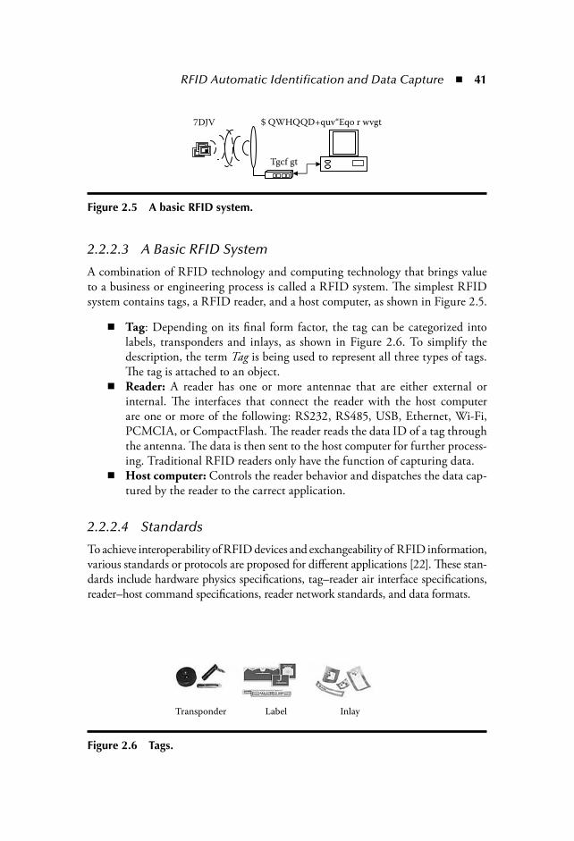
RFID Automatic Identification and Data Capture 41
2.2.2.3 A Basic RFID System
A combination of RFID technology and computing technology that brings valueto a business or engineering process is called a RFID system. The simplest RFIDsystem contains tags, a RFID reader, and a host computer, as shown in Figure 2.5.
Tag: Depending on its final form factor, the tag can be categorized intolabels, transponders and inlays, as shown in Figure 2.6. To simplify thedescription, the term Tag is being used to represent all three types of tags.The tag is attached to an object.
Reader: A reader has one or more antennae that are either external orinternal. The interfaces that connect the reader with the host computerare one or more of the following: RS232, RS485, USB, Ethernet, Wi-Fi,PCMCIA, or CompactFlash. The reader reads the data ID of a tag throughthe antenna. The data is then sent to the host computer for further process-ing. Traditional RFID readers only have the function of capturing data.
Host computer: Controls the reader behavior and dispatches the data cap-tured by the reader to the carrect application.
2.2.2.4 Standards
To achieve interoperability of RFID devices and exchangeability of RFID information,various standards or protocols are proposed for different applications [22]. These stan-dards include hardware physics specifications, tag–reader air interface specifications,reader–host command specifications, reader network standards, and data formats.
7DJV
Tgcf gt
$ QWHQQD+quv“Eqo r wvgt
Figure 2.5 A basic RFID system.
Transponder Label Inlay
Figure 2.6 Tags.

42 The Internet of Things
International Standards Organizations (ISO) 18000 series of standards defineRFID air interface operations, which include physical layer electronic characteris-tics and data link layer for data communication. ISO 18000 contains seven parts:
Part 1 defines general parameters.Part 2 specifies the parameters for frequency under 125 KHz (LF).Part 3 specifies parameters for 13.56MHz (HF).Part 3 and Part 4 work on 2.45 GHz and 5.8 GHz, respectively.Part 6 works on frequency between 860 MHz to 930 MHz (UHF).Part 7 works on 433 MHz (used for active RFID).
Besides the ISO 18000 series of standards, ISO 14443 and ISO 15693 define the airinterface and communication protocols for the proximity system and vicinity card. ISO14223 defines the air interface for identification of animals in agricultural applications.
Along with the air interface definitions, there are additional standards for rectifyingthe processes of tagging, packaging, data coding, and other special applications. Forexample, ISO 15961-15963 series define the concept, data syntax, business process, andinformation exchange for item level management; ISO 17363-17368 define the differ-ent types of packaging processes for the logistic and supply chain. ISO 11784 and ISO11785 define the code structure and application concept for animal identification. Foreach RFID technology there is a conformance test standard to guide its use and test.
The Electronic Product Code (EPC) [23] was originally developed by the AutoID Center at the Massachusetts Institute of Technology (MIT). In 2003, the AutoID Center licensed the EPC technologies to EPCglobal, a joint venture betweenEuropean Article Number (EAN) International and the Uniform Code Council,Inc. Since then, EPCglobal has taken the mission of standardizing and develop-ing hardware physics, communication protocols, the EPC network infrastructurespecifications, the supported software specifications, and data formats.
EPCglobal defines the EPC classes according to the functional characteristics.The classes are [24]:
Class 0: “Read Only” passive tags. The ID is programmed by the manufacturer.Class 1: “Write-Once, Read-Many” passive tags. The ID is programmed bythe user and locked to prevent rewrite.Class 1 Generation-2 (Gen-2): An updated version of the Generation-1. Itsupports more secure operations and contains optional user memory.Class 2: Multiple Read/Write passive tags. It contains user memory thatallows updating and encrypting.
Class 3: Multiple Read/Write semipassive tags with user memory. Class 4: Active tags. Class 5: Readers.
The information exchange of the EPC complaint application is based on the datastructure or coding scheme defined in the EPC standards. The first generation of the

RFID Automatic Identification and Data Capture 43
EPC coding scheme is quite simple. The 96 bits or 64 bits of a RFID tag number hasbeen divided into four segments, which include: Header, EPC Manager, Object Class,and Serial Number. However, this scheme cannot represent the current global tradingbusiness-related identification numbers. The latest EPC coding scheme supports morecoding that is being used in current global trading business. These coding schemesinclude: Serialized Global Trade Identification Number (SGTIN), Serial Shipping Con-tainer Code (SSCC), Serilized Global Location Number (GLN), Global ReturnableAsset Identifier (GRAI), Global Individual Asset Identifier (GIAI), and General Identi-fier (GID). The identification coding scheme for the U.S. Department of Defense (DoD)are also supported in the EPCglobal EPC tag standard document [25]. The EPC Gen-2air interface protocol for UHF communication has been proved as ISO 18000-6C [26].
2.2.2.5 Advantages and Disadvantages
Compared with other identification technologies, RFID has the followingadvantages:
1. High reading speed, multiple reading and writing simultaneously: Dependingon the technology used, the reading speed of RFID can be up to 1000 tags/sec [23]. Higher reading speed leads to higher throughput in the system. Forexample, in a high-speed sorting system, the throughput could be improvedsignificantly by improving the speed of identifying an item, which could bethe bottleneck of the system. Inventory management would be improved byusing RFID because the item-by-item manual checking can be substitutedwith an automated method.
2. The RFID technology does not need to be line-of-sight. For example,when shipping a container with RFID tags installed on products withinthe container, it is not necessary to open the container and read the taggeditems one-by-one because the readers can typically read tag data through oraround blocking materials.
3. The data carried by an RFID tag is rewritable. The memory storage rangesfrom several bytes to a few megabytes. With the user memory, the businessinformation carried by the tag can be changed during any point of theprocess dynamically. More data can be carried on the tag itself so that thetightly coupled back end database may not be required, which is not thecase in the traditional AIDC approach.
4. RFID has a longer reading/writing range compared to barcodes and mostother identification technologies. The sensing range of RFID tags variesfrom a few centimeters to hundreds of meters [20].
5. Security checks can be added into RFID tags to prevent unauthorized read-ing and writing. Fear of the disclosure of privacy slows down the practice ofmany advance technologies. The RFID is one of them. Fortunately, a moresophisticated authentication encryption algorithm is being implemented

44 The Internet of Things
in the RFID tags and readers. By adding such security check functionsinto the implementation, RFID is becoming the dependable technology toprevent ID theft and counterfeiting. On the contrary, its close counterpart—barcode—does not have such capability.
6. The combination of RFID and sensor technology could bring more value toenterprise applications. For example, during the food transportation, it is impor-tant that the temperature of the food be monitored and controlled. Normally thetemperature is set on the refrigeration device. In a large container, the temperaturemay vary at different points within the containers, especially when large numbersof items are being transported. An RFID tag combined with a temperature sen-sor could locate and precisely monitor the status of each individual item.
Therefore, RFID is more effective when faster processing, longer read range,flexible data carrying capability and more secure transactions are required. Some ofthe widely acknowledged benefits of RFID are that it could:
1. Improve warehouse and distribution productivity. 2. Improve retail and point-of-sale productivity. 3. Reduce out-of-stock and shrinkage. 4. Help prevent the insertion of counterfeit products into supply chains. [27].
However, despite these obvious advantages, there exist some disadvantages as well:
1. A major drawback of RFID is its cost. The current price for each UHF tagis still costly. The RFID industry is trying hard to reduce the manufactur-ing cost. Within a few years, the industry hopes to reduce the cost to about3 cents per tag for UHF tags. A 5 cent RFID tag is already available [28].
2. Reading and writing reliability are largely affected by the material of thetagged product and its surrounding environment. For example, it is dif-ficult to read a UHF RFID tag surrounded by liquid or metal. By studyingthe physics and doing experiments, we observed that by properly placing orencapsulating the RFID tag, the reading performance was improved [29].New methodologies are being developed to overcome the challenges facedby environmental factors. For example, new UHF tags and readers basedon Near-Field Communication (NFC) developed by Impinj demonstratesthat NFC UHF RFID tags can be read even when the tags are in liquid[30]. Various tag encapsulation methods and RF technologies are beingresearched to improve the performance of RFID. We believe that theseproblems will be solved by technological advancements in this field.
2.2.3 Sensor TechnologiesThe sensor is a device that can measure and collect environmental parameters (suchas temperature, humidity, chemicals, vibration, density, etc.) or system run-time parameters (such as position, location, speed, acceleration, etc.) [31]. Sensors have been
RFID Automatic Identification and Data Capture 45
used in a variety of applications, especially for automation and control in industries,such as aerospace, automotive, healthcare, environment, transportation, etc. As thesmallest unit of an automation system, a single sensor can be used for fulfilling cer-tain functions. But, in most cases, a sensor system consists of a large number of sen-sors that must work together to achieve awareness of the physical surroundings.
Recently, new technologies, including wireless sensors, MEMS sensors, smartsensors, bio sensors, etc., have changed the type of sensors that can be made. Sen-sors made today with advanced techniques are smaller and can measure and collectinformation that is beyond the capability of traditional sensors. New sensor systeminfrastructures, such as sensor network [32] with wireless connection capability, aregradually replacing the traditional wire-connected sensors.
In an enterprise environment, sensor technologies combined with ID tech-nologies would significantly improve the enterprise resource visibility and, thus,improve the enterprise operation efficiency. For example, along the supply chainflow, a global positioning system (GPS) sensor could help the enterprise systemtrack and monitor the location of the raw material in real-time [33]. A better deci-sion on the related enterprise operations could then be made based on informationof not only on the location of an asset, but also its condition and, then possibly,the condition of the asset could alter where it was being next sent (for example, ificecream was being shipped at high temperatures, it could be disposed of instead ofcontinuing to the final destination).
2.3 AIDC InfrastructureThe advantages of identification technologies can potentially improve the enter-prise operation efficiency and reduce the operation cost. However, simply deployingdata-capturing devices, assigning identification data to the business object, andcapturing the data from the business object cannot alone bring value to enter-prise operations. A set of software components, which assist devices management,identification data preparing, capturing, formatting, and associating with physi-cal objects, are required. The software components and devices together are calledidentification resources. Further, these identification resources are networked andcollaborate with each other to form the AIDC infrastructure.
2.3.1 Definitions and ComponentsThe AIDC infrastructure is defined as a set of networked devices and softwarecomponents, which include:
Devices: Various identification technologies, such as RFID reader, RFIDprinter, barcode scanner, sensors, Programmable Logic Controller (PLC), etc.Services: Software components that enable the data preparation, captur-ing, and processing.
46 The Internet of Things
Essential components of an AIDC infrastructure are identified [34] [35] andillustrated in Figure 2.7. It contains the following components:
Barcodes, Tags, and Sensors: The smallest units that are attached to anenterprise entity or resource to be identified.Device Controller or Edge Server: A device controller is used to manageand control identification hardware (readers, scanners, sensors and othermanageable devices), aggregate, preprocess, and cache the identificationinformation. It is difficult to manage a device in a planer space. Putting allthe functions, such as capture, process, and representation of identificationdata, into a single server could increase the burden of the server. Hierarchi-cal, layered, and distributed architecture is an effective way to balance theload and deliver the best overall performance. Using the edge servers, thedevices can be clustered and distributed. Functional roles can be separatedso that the edge servers can be dedicated to the data capture requirementswhere the core and central servers can be used for data intelligence.Identification Network: The infrastructure that connects all of the hard-ware resources and enterprise information systems together.Enterprise Information Servers: Provides enterprise activities-relateddata, which can be used along with the identification information for busi-ness operations. It provides real-time, aggregated identification data and
6HQVRU
6\VWHP
6HQVRU
6HQVRU
6HQVRU
7DJV
5HDGHU
5HDGHU
%DUFRGHV
(GJH 6HUYHU)
(QWHUSULVH
,QIRUPDWLRQ 6HUYHUV)
(QWHUSULVH
$SSOLFDWLRQ)
(QWHUSULVH
,GHQWLILFD
1HWZRUN)
,HYLFH & RQWUROOHU
(GJH 6HUYHU)
Figure 2.7 The AIDC infrastructure.

RFID Automatic Identification and Data Capture 47
events to client applications. As discussed earlier, the identification datacapture process may contain business events. The Enterprise InformationSystem provides interfaces so that the application can define, register, andlook up events. It also provides interfaces that the end application can regis-ter and look up production information, business information, and transac-tion information that is associated with a particular identification data.Enterprise Application: Functional modules that fulfill certain enterpriseactivities. For example, a Warehouse Management System uses the datacaptured by the edge server to monitor the inventory level; an Asset Man-agement System uses the data to look up a particular asset, etc.
Identification data carried by barcodes, RFID tags, and sensors is collected by adata capturing device and passed on to the edge servers or device controllers. It is pro-cessed at the edge server before being sent into the network. The components are notstandalone—they are networked with other components and can exchange informa-tion with each other. For example, the identification data captured by one edge servercan be used as the reference to generate an event by next edge server. If the numberof IDs on the same pallet has been read differently by different edge servers, an eventindicating that there is a missing product would be generated.
2.3.2 Challenges of Creating RFID-Oriented AIDC Infrastructures
As advanced AIDC technologies, such as RFID, are introduced, the challenges ofcreating AIDC infrastructures are present. The challenges are:
1. The performance of data capture and processing: High volume of data is requiredto be captured and processed at high speed. First the RFID system reads data10 to 100 times faster than traditional barcode scanning [17]. Second, theability to read at much greater distances and in larger region volumes aroundthe reader results in greater volumes of data generated due to larger numbersof tags in the read-range of a reader. For example, if a carton has 100 taggeditems, RFID reader is able to read all the items in less than one second becausethe UHF RFID reader has the ability to read up to 1000 reads/sec [23]. Thus,it is important that the AIDC infrastructure has the ability to capture suchhigh volume data and rapidly send it to the end application. Providing real-time, accurate, and consistent data is the key to a streamlined enterprise opera-tion. If the data is not accurate or is out of date, the wrong decision madebased on the data would be costly to the enterprise. For example, consider thecase of a supply chain in which the data captured during the transportation ofgoods cannot be sent to the ordering system on time. To control the inventoryat a given level, the ordering system may request another order to fulfill theinventory control and this can result in duplicate orders.
48 The Internet of Things
2. The manageability and extensibility of heterogeneous devices: Co-existence ofvarious identification devices makes them extremely difficult to manage,deploy, and configure. The diversity of RFID technologies (various stan-dards, different frequencies, and utilizing passive and active technology)increases the difficulty of managing the data capturing devices. How toeffectively manage devices and how to adopt new devices without signifi-cantly modifying the AIDC infrastructure needs to be researched.
3. Scalability and performance of the AIDC infrastructure: As high-volume data isbeing captured by the data capturing devices at high speed, how to ensure thatthe performance of the system would not degrade dramatically as the AIDCinfrastructure grows can be a problem. For example, 7 terabyte data generatedby the Wal-Mart RFID trial every day is reported in [36]. How to handle suchhigh volume data in an AIDC infrastructure is challenging.
4. Discoverability and availability of resources: In a large scale enterprise environ-ment, various services may be deployed in a logically and geometrically dis-tributed environment. The client needs to find the right resource and obtainuseful data from it. Either using the on-demand request (pull) or the real-time event (push) approach to provide the data and resource, the identifica-tion resources should be available and consumable to the client at any time.
5. The integration of various identification resources with the diverse EIS: Thetasks of an AIDC infrastructure are not just to capture identification data.It acts as a bridge which it flawlessly connects all EIS together. However, thediversity of the data formats, especially when customized data is involved,increase the complexity of the data processing for the end application. Theidentification data should be associated with the physical object or businesstransaction so that it can be used in the EIS system.
2.4 SummaryA variety of identification technologies have been used in the enterprise systems toimprove the operation efficiency and reduce the overall operation cost. Barcodes,RFID, and sensors are the most commonly used and important technologies thathave been addressed. Because of its low cost, the barcode is the major identificationtechnology used by most enterprises today. The emerging RFID technology bringssignificant new opportunities as well as challenges to the AIDC infrastructure. Thecombination of RFID and sensor technology adds additional value to the enterpriseoperations. For example, by combining the temperature sensor and RFID tag, thereader obtains the environment temperature of the tagged object. This is useful incold chain where the temperature of the transporting product has to be preciselymonitored and controlled. Although the RFID technology still has limitations,such as tag readability due to physical constraints, enterprises are increasingly usingRFID to assist their business operations because of the advantages it brings.

RFID Automatic Identification and Data Capture 49
Because of the emerging RFID technology and the diversity of identificationdevices, challenges exist in implementing an AIDC infrastructure. The challengesconsist of the performance of data capture and processing, the manageability andextensibility of heterogeneous devices, scalability and performance of the AIDCinfrastructure, discoverability and availability of resources, and the integration ofvarious identification resources with the diverse EIS. Important topics of currentAIDC research include the extensibility, scalability, resources usability and discov-erability, RFID system performance, device manageability, and system integrationability of AIDC infrastructures.
References [1] Christina Soh, Sia Siew Kien, and Joanne Tay-Yap, Enterprise resource planning:
cultural fits and misfits: Is ERP a universal solution? Communications of ACM, 43,47–51, 2000.
[2] Benita M. Beamon, Supply chain design and analysis: Models and methods, Inter-national Journal of Production Economics, 55, 281–294, 1998.
[3] D.M. Lambert and M.C. Cooper, Issues in supply chain management, Industrial Marketing Management, 29, 65–83, 2000.
[4] Valerie Thomas, Wolfgang Neckel, and Siguad Wagner, Information technologyand product lifecycle management, In Proceeding of the 1999 IEEE InternationalSymposium on Electronics and the Environment.
[5] Ioannis Komninos, “Production Life Cycle Management.” http://www.urenio.org/tools/en/Product_Life_Cycle_Management.pdf (accessed ).
[6] M. Stone, N. Woodcock, and M. Wilson, Managing the change from marketingplanning to customer relationship management, International Journal of Strategic Management: Long Range Planning, 29, 5: 675–683(9), October 1996.
[7] Russell S. Winer, “Customer Relationship Management: A Framework, ResearchDirections, and the Future.” http://groups.haas.berkeley.edu/fcsuit/PDF-papers/CRMpaper.pdf, accessed November 2006.
[8] Ronelle Russell, Manufacturing execution systems: Moving to the next level, Phar-maceutical Technology, January 2004, 38–50.
[9] Ben Worthen, “The ABCs of Supply Chain Management.” http://www.cio.com/research/scm/edit/012202_scm.html, accessed November 2006.
[10] IBM, “Enterprise Asset Management: Optimizing Business Operation with Lead-ing-Edge Enterprise Asset Management Services.” http://www935.ibm.com/ser-vices/us/index.wss/offering/bcs/a1002719, accessed November 2006.
[11] Diane M. Strong and Olga Volkoff, A roadmap for enterprise system implementa-tion, Computer, June 2004, 22–29.
[12] Cambridge Consultant, “Description of Technologies and Example of Applicationin Other Industries.” http://www.npsa.nhs.uk/site/media/documents/811_Cam-bridge ConsultantsReportSection 2.pdf, accessed November 2006.
[13] Mery Bellis, “Bar Codes.” http://inventors.about.com/library/inventors/blbar_code.htm,accessed November 2006.
50 The Internet of Things
[14] GS1 US, “The Universal Product Code.” http://www.uccouncil.org/upc_back-ground.html, accessed November 2006.
[15] “Scanning technologies” http://www.mecsw.com/reviews/scanners/scantech.html, accessed November 2006.
[16] “Bar codes” http://www.lintech.org/comp-per/06BARCD.pdf, accessed November 2006. [17] J. Abernethy, “Bar Codes & RFID, An Engineering Science 96 Report, M17,”
1995. http://www.deas.harvard.edu/courses/es96/spring1995/barcodes_rfid/aber-nethy.html, accessed November 2006.
[18] Alexander Brewer, Nancy Sloan, and Thomas L. Landers, Intelligent tracking inmanufacturing, Journal of Intelligent Manufacturing, 10, 245–250, 1999.
[19] Jerry Landt, “Shrouds of Time: The History of RFID.” http://www.aimglobal.org/technologies/rfid/resources/shrouds_of_time.pdf, accessed November 2006.
[20] K. Finkenzeller and G. Munich, Radio-frequency identification: Fundamentalsand application, RFID Handbook, John Wiley & Sons, New York, 1999.
[21] EPCglobal, “Regulatory status for using RFID in the UHF spectrum, Nov. 24,2006.” http://www.epcglobalinc.org/tech/freq_reg/RFID_at_UHF_Regulations_20061124.pdf, accessed December 2006.
[22] Craig K. Harmon, “RFID Standards.” http://www.autoid.org/2002_Documents/hottopics/Standards_20020324.ppt.
[23] EPCGlobal, “Standards.” http://www.epcglobalinc.org/standards, accessed December2006.
[24] Impinj, “RFID Standards.” http://www.impinj.com/page.cfm?ID=aboutRFIDStandards, accessed December 2006.
[25] EPCglobal, “EPC Generation 1 Tag Data Standards Version 1.1 Rev. 1.27, StandardSpecification, 10 May 2005.” http://www.epcglobalinc.org/standards, accessedDecember 2006.
[26] Mary C. O’Connor, Gen 2 EPC protocol approved as ISO 18000-6C, RFID Journal.http://www.rfidjournal.com/article/articleview/2481/1/1, accessed December 2006.
[27] Tom Pisello, The ROI of RFID in the supply chain, RFID Journal, August, 2006. http://www.rfidjournal.com/article/articleprint/2602/-1/1, accessed November 2006.
[28] Mark Roberti, A 5-cent breakthrough, RFID Journal. http://www.rfidjournal.com/article/articleview/2295, accessed November 2006.
[29] Tadej Semenic, RFID radio study, RFID System Course project report, WIN-MEC, UCLA, Fall 2005.
[30] Impinj, “Impinj GrandPrix In Action.” http://www.impinj.com/page.cfm?ID=RFIDVideos, accessed January 2007.
[31] Ljubisa Ristic, Sensor Technology and Devices, Artech House Publishers, Norwood,MA, 1994.
[32] Jason Hill, Robert Szewczyk, Alec Woo, Seth Hollar, David Culler, and KristoferPister, System architecture directions for networked sensors, in Proceedings of the9th International Conference on Architectural Support for Programming Lan-guages and Operating Systems, ACM, Cambridge, MA, Nov. 2000, 93–104.
[33] Harish Ramamurthy, Dhananjay Lal, B.S. Prabhu, and Rajit Gadh, Re,WINS: A dis-tributed multi-RF sensor control network for industrial automation, IEEE WirelessTelecommunications Symposium (WTS 2005), April 28–30, 2005, Pomona, CA,pp. 24–33.
RFID Automatic Identification and Data Capture 51
[34] B.S. Prabhu, Xiaoyong Su, Harish Ramamurthy, Chi-Cheng Chu, and Rajit Gadh,WinRFID—A middleware for the enablement of Radio Frequency Identification(RFID)-based applications, in Mobile, Wireless and Sensor Networks: Technology,Applications and Future Directions, Rajeev Shorey, Chan Mun Choon, Ooi WeiTsang, and A. Ananda (Eds.), John Wiley & Sons, New York, 2005.
[35] B.S. Prabhu, Xiaoyong Su, Charlie Qiu, Harish Ramamurthy, Peter Chu, and RajitGadh, WinRFID—Middleware for distributed RFID infrastructure, InternationalWorkshop on Radio Frequency Identification (RFID) and Wireless Sensors, IndianInstitute of Technology, Kanpur, India, November 11–13, 2005.
[36] Evan Schuman, “Will Users Get Buried Under RFID Data?” Ziff Davis Inter-net, November 9, 2004, http://www.eweek.com/article2/0,1895,1722063,00.asp,accessed January 2007.
[37] A.D. Smith and F. Offodile, Information management of automatic data capture:An overview of technical developments, Information Management & Computer Security, 10, 2–3: 109–118, 2002.
[38] Anish Shah and Hiral Patel, Tag performance with Samsys 9320, RFID SystemCourse Project, WINMEC, UCLA, Fall 2004.
[39] Seung Ryong Han and Jim Shaughhessy, Comprehensive reader and tag test(AWID), RFID System Course Project, WINMEC, UCLA, Fall 2004.
[40] Rajit Gadh and B.S. Prabhu, Radio frequency identification of Katrina hurricanevictims, IEEE Signal Processing, March 2006.


53
Chapter 3
RFID Data Warehousing and Analysis
Hector Gonzalez and Jiawei Han
Contents3.1 Introduction ..............................................................................................54
3.1.1 Redundancy Elimination................................................................553.1.2 Bulky Movement Compression.......................................................553.1.3 EPC List Compression....................................................................563.1.4 Aggregation Along Concept Hierarchies.........................................56
3.2 RFID Data ................................................................................................573.3 Architecture of the RFID Warehouse ........................................................58
3.3.1 Key Ideas of RFID Data Compression............................................593.3.1.1 Taking Advantage of Bulky Object Movements .............. 603.3.1.2 Taking Advantage of Data Generalization....................... 603.3.1.3 Taking Advantage of the Merge or Collapse
of Path Segments ............................................................. 603.3.2 RFID-CUBOID ............................................................................61
3.3.2.1 Information Table.............................................................613.3.2.2 Stay Table .........................................................................623.3.2.3 Map Table ........................................................................63
3.3.3 Lattice of RFID-Cuboids .............................................................. 64

54 The Internet of Things
3.1 IntroductionRadio Frequency IDentification (RFID) is a technology that allows a sensor (RFIDreader) to read, from a distance and without line of sight, a unique identifier thatis provided (via a radio signal) by an “inexpensive” tag attached to an item. RFIDoffers a possible alternative to barcode identification systems and it facilitates appli-cations like item tracking and inventory management in the supply chain. Thetechnology holds the promise to streamline supply chain management, facilitaterouting and distribution of products, and reduce costs by improving efficiency.
Large retailers like Wal-Mart, Target, and Albertsons have already begunimplementing RFID systems in their warehouses and distribution centers, and arerequiring their suppliers to tag products at the pallet and case levels. Individualtag prices have been steadily falling, and, in the near future, it is expecting to seeitem-level tagging for many products. The main challenge then becomes how cancompanies handle and interpret the enormous volume of data that a RFID applica-tion generates. Venture Development Corporation [20], a research firm, predictsthat when tags are used at the item level, Wal-Mart will generate nearly 7 terabytesof data every day. Database vendors like Oracle, IBM, Teradata, and some startups
3.4 Construction of an RFID Warehouse........................................................653.4.1 Construction of Higher Level RFID-CUBOIDs from Lower
Level Ones..................................................................................... 663.5 Query Processing .......................................................................................68
3.5.1 OLAP.............................................................................................683.5.1.1 Rollup...............................................................................683.5.1.2 Drill Down.......................................................................693.5.1.3 Slice and Dice...................................................................69
3.5.2 Path Query Processing....................................................................693.6 Performance Study.....................................................................................71
3.6.1 Data Synthesis ................................................................................723.6.2 RFID-Cuboid Compression ...........................................................723.6.3 Query Processing............................................................................74
3.7 Discussion..................................................................................................763.7.1 Related Work................................................................................. 773.7.2 Open Issues ................................................................................... 77
3.7.2.1 Incremental Update ..........................................................783.7.2.2 Construction of a Fading RFID Warehouse Model ..........783.7.2.3 Data Mining in the RFID Warehouse..............................783.7.2.4 Warehousing Scattered Movement Data...........................79
3.8 Conclusions ...............................................................................................79References ...........................................................................................................79
RFID Data Warehousing and Analysis 55
are beginning to provide solutions to integrate RFID information into their enter-prise data warehouses.
Example: Suppose a retailer with 3,000 stores sells 10,000 items a day per store.Assume that we record each item movement with a tuple of the form (EPC location time), where the electronic product code (EPC) uniquely identifies each item.* Ifeach item leaves only 10 traces before leaving the store by going through differentlocations, this application will generate at least 300 million tuples per day. A man-ager may make queries on the duration of paths, like (Q1): “List the average shelf lifeof dairy products in 2003 by manufacturer,” or on the structure of the paths, like(Q2): “What is the average time that it took coffeemakers to move from the ware-house to the shelf and finally to the checkout counter in January of 2004?” Newdata structures and algorithms need to be developed that will provide fast responsesto such queries even in the presence of terabyte-sized data.
Such enormous amounts of low-level data and flexible high-level queries posegreat challenges to traditional relational and data warehouse technologies becausethe processing may involve retrieval and reasoning over a large number of inter-related tuples through different stages of object movements. No matter how theobjects are sorted and clustered, it is difficult to support various kinds of high-levelqueries in a uniform and efficient way. A nontrivial number of queries may evenrequire a full scan of the entire RFID database.
In order to conduct efficient analysis over large RFID data sets it is important toeliminate data redundancy, perform lossless data compression by aggregating bulkyobject movements, and perform lossy data compression by registering data at highlevels of abstraction.
3.1.1 Redundancy EliminationIt is important to eliminate the redundancy present in RFID data. Each reader pro-vides tuples of the form (EPC location time) at fixed time intervals. When an itemstays at the same location for a period of time, multiple tuples will be generated.These tuples can be grouped into a single one of the form (EPC, location, time_in, time_out). For example, if a supermarket has readers on each shelf that scan theitems every minute, and items stay on the shelf on average for one day, we get a1,440 to 1 reduction in size without loss of information.
3.1.2 Bulky Movement CompressionItems tend to move and stay together through different locations. For example, apallet with 500 cases of compact discs (CDs) may arrive at the warehouse; from
* We will use the terms EPC and RFID tag interchangeably throughout the chapter.

56 The Internet of Things
there, cases of 50 CDs may move to the shelf; and from there, packs of 5 CDs maymove to the checkout counter. A single stay tuple of the form (EPC_list, location, time_in, time_out) can be used to register the CDs that arrive in the same palletand stay together in the warehouse, and, thus, generate a 80 percent space saving.
An alternative compression mechanism is to store a single transition record for the50 CDs that move together from the warehouse to the shelf, i.e., to group transitionsand not stays. The problem with transition compression is that it makes it difficult toanswer queries about items at a given location or going through a series of locations.For example, in order to answer the query: What is the average time that CDs stay at the shelf? you can directly get the information from the stay records with location shelf,but if only transition records are available, you need to find all the transition recordswith origin shelf and the ones with destination shelf join them on the EPC andcompute departure time–arrival time. Another method of compression would be tolook at the sequence of locations that an item goes through as a string, and use a Trie[6] to store the strings. The Trie data structure is a tree where each node is associatedwith a string prefix, and all descendant of the node share the prefix. The problem withthis approach is that you lose compression power. In the CDs example, if the 50 itemsall stay at the warehouse together, but they come from different locations, a trie wouldhave to create distinct nodes for each, thus gaining no compression.
3.1.3 EPC List CompressionFurther compression can be gained by reducing the size of the EPC lists in the stayrecords by grouping items that move to the same location. For example, if you havea stay record for the 50 CDs that stayed together at the warehouse, and later theseCDs moved in two groups to the shelf and truck locations, it is possible to replacethe list of 50 EPCs in the stay record for just two generalized identifiers (gids),which in turn point to the concrete EPCs. In this example, we will store a total of50 EPCs, plus two gids, instead of 100 EPCs (50 in the warehouse, 25 on shelf,25 in truck). In addition to the compression benefits, query processing speedup isgained by assigning path-dependent names to the gids. In the CDs example, youcould name the gid for the warehouse 1, and the gid for the shelf 1.1, and for thetruck 1.2. If you get a query asking for the average time to go from the warehouseto the shelf for CDs, instead of intersecting the EPC lists for the stay records ateach location, you can directly look at the gid name and determine if the EPCs arelinked. The path-dependent naming scheme provides the benefits of a tree structurerepresentation of a trie without taking a significant compression penalty.
3.1.4 Aggregation Along Concept HierarchiesMost queries are likely to be at a high level of abstraction, and will only be inter-ested in the low-level individual items if they are associated with some interesting
RFID Data Warehousing and Analysis 57
patterns discovered at a high level. For example, query (Q1) asks about dairy prod-ucts by a manufacturer. It is possible after seeing the results, the user may makesubsequent queries and drill down to individual items. Significant compression canbe achieved by creating the stay records not at the raw level, but at a minimal levelof abstraction shared by most applications while keeping pointers to the RFID tags.This allows the system to operate on a much smaller dataset, fetching the originaldata only when absolutely necessary.
3.2 RFID DataData generated from a RFID application can be seen as a stream of RFID read-ings of the form (EPC, location, time), where EPC is the unique identifier read bya RFID reader, location is the place where the RFID reader scanned the item, andtime is when the reading took place. Tuples are usually stored according to a timesequence. A single EPC may have multiple readings at the same location, eachreading is generated by the RFID reader scanning for tags at fixed time intervals.Table 3.1 is an example of a raw RFID database where a symbol starting with rrepresents a RFID tag, l a location, and t a time. The total number of records inthis example is 188.
In order to reduce the large amount of redundancy in the raw data, data clean-ing should be performed. The output after data cleaning is a set of clean stay recordsof the form (EPC, location, time_in, time_out) where time_in is the time whenthe object enters the location and time_out is the time when the object leaves thelocation.
Data cleaning of stay records can be accomplished by sorting the raw data onEPC and time, and generating time_in and time_out for each location by merg-ing consecutive records for the same object staying at the same location. Table 3.2presents the RFID database of Table 3.1 after cleaning. It has been reduced from188 records to just 17.
Table 3.1 Raw RFID RecordsRaw Stay Records
(r1, l1, t1) (r2, l1, t1) (r3, l1, t1) (r4, l1, t1) (r5, l1, t1) (r6, l1, t1)
(r7, l1, t1) (r1, l1, t9) (r2, l1, t9) (r3, l1, t9) (r4, l1, t9) (r1, l1, t10)
(r2, l1, t10) (r3, l1, t10) (r4, l1, t10) (r7, l4, t10) (r7, l4, t19)
(r1, l3, t21) (r2, l3, t21) (r4, l3, t21) (r5, l3, t21) (r6, l6, t35)
(r2, l5, t40) (r3, l5, t40) (r6, l6, t40) (r2, l5, t60) (r3, l5, t60)

58 The Internet of Things
3.3 Architecture of the RFID WarehouseSuppose that the cleansed RFID data is viewed as a fact table with dimensions(EPC, location,time_in,time_out:measure). A traditional data cube will compute allpossible groupings (group-bys) on this fact table by aggregating records that sharethe same values (or any *) at all possible combinations of dimension. If you usecount as measure, you can get, for example, the number of items that stayed at agiven location for a given month. The problem with this form of aggregation is thatit does not consider links between the records. For example, if you want to get thenumber of items of “dairy product” that traveled from the distribution center inChicago to stores in Urbana, the information is lost. You have the count of “dairyproducts” for each location, but you do not know how many of these items wentfrom the first location to the second. A more powerful cubing model capable ofaggregating data while preserving its path-like structure is needed.
A new model of RFID warehouse architecture should contain a fact table,stay, composed of cleansed RFID records; an information table, info, that storespath-independent information for each item, i.e., SKU information that is con-stant regardless of the location of the item such as manufacturer, lot number, color,etc.; and a map table that links together different records in the fact table thatform a path. Figure 3.1 shows a logical view into the RFID warehouse schema.The stay, info, and map tables aggregated at a given abstraction level are called aRFID-Cuboid.
The main difference between the RFID warehouse and a traditional warehouseis the presence of the map table linking records from the fact table (stay) in order topreserve the original structure of the data.
The computation of RFID-Cuboids is more complex than that of regularcuboids as data aggregation has to preserve the structure of the paths traversedby EPCs at different abstraction levels. From the data storage and query process-ing point of view, the RFID warehouse can be viewed as a multilevel database,organized as in Figure 3.2. The raw RFID repository resides at the lowest level;
Table 3.2 A Cleansed RFID DatabaseEPC Stay (EPC, location, time_in, time_out)
r1 (r1, l1, t1, t10) (r1, l3, t20, t30)
r2 (r2, l1, t1, t10) (r2, l3, t20, t30) (r2, l5, t40, t60)
r3 (r3, l1, t1, t10) (r3, l3, t20, t30) (r3, l5, t40, t60)
r4 (r4, 1, t1, t10)
r5 (r5, l2, t1, t8) (r5, l3, t20, t30) (r5, l5, t40, t60)
r6 (r6, l2, t1, t8) (r6, l3, t20, t30) (r6, l6, t35, t50)
r7 (r7, l2, t1, t8) (r7, l4, t10, t20)

RFID Data Warehousing and Analysis 59
on its top are the cleansed RFID database, the minimum abstraction level RFID-Cuboids, and a sparse subset of the full cuboid lattice composed of frequently que-ried (popular) RFID-Cuboids.
3.3.1 Key Ideas of RFID Data CompressionEven with the removal of data redundancy from RFID raw data, the cleansed RFIDdatabase usually is still enormous. In this section, we will elaborate on the concepts
Product MAP
InfoLocation
Time
Stay
category
lot number
EPC list
product
manufacturer
color
price
reader_loc
locale
building
city
second
minute
hour
day
month
gids
location
time_in
time_out
measure
gid
gids
Figure 3.1 RFID Warehouse—Logical Schema.
Materialized RFID-Cuboids
Minimum Abstraction RFID-Cuboid
Cleansed RFID Data
Raw RFID Data
Figure 3.2 The architecture of a RFID warehouse.

60 The Internet of Things
of compression presented in the introduction, as these are essential to understandthe RFID-Cuboid structure.
3.3.1.1 Taking Advantage of Bulky Object Movements
Since a large number of items travel and stay together through several stages, it isimportant to represent such a collective movement by a single record no matter howmany items were originally collected. As an example, if 1,000 boxes of milk stayedin location locA between time t1 (time_in) and t2 (time_out), it would be advanta-geous if only one record is registered in the database rather than 1,000 individualRFID records. The record would have the form: (gid, prod, locA, t1, t2, 1000), where1,000 is the count, prod is the product id, and gid is a generalized id, which willnot point to the 1,000 original EPCs, but instead point to the set of new gids thatthe current set of objects move to. For example, if this current set of objects weresplit into 10 partitions, each moving to one distinct location, gid will point to 10distinct new gids, each representing a record. The process iterates until the end ofthe object movement where the concrete EPCs will be registered. By doing so, noinformation is lost, but the number of records to store such information is substan-tially reduced.
3.3.1.2 Taking Advantage of Data Generalization
Since many users are only interested in data at a relatively high abstraction level,data compression can be explored to group, merge, and compress data records. Forexample, if the minimal granularity of time is hours, then objects moving withinthe same hour can be seen as moving together and be merged into one movement.Similarly, if the granularity of the location is shelf, objects moving to the differentlayers of a shelf can be seen as moving to the same shelf and be merged into one.Similar generalizations can be performed for products (e.g., merging different sizedmilk packages) and other data as well.
3.3.1.3 Taking Advantage of the Merge or Collapseof Path Segments
In many analysis tasks, certain path segments can be ignored or merged for sim-plicity of analysis. For example, some nonessential object movements (e.g., fromone shelf to another in a store) can be completely ignored in certain data analysis.Some path segments can be merged without affecting the analysis results. For storemanagers, merging all the movements before the object reaches the store could bedesirable. Such merging and collapsing of path segments may substantially reducethe total size of the data and speed up the analysis process. Figure 3.3 presents twodifferent path collapsing schemes. The path in the top is the view of a store manager

RFID Data Warehousing and Analysis 61
that is only concerned with detailed movements inside the store. The path at thebottom is the view of a transportation manager, only interested in detailed move-ments related to transportation locations.
3.3.2 RFID-CUBOIDWith the data compression principles in mind, the RFID-Cuboid can be defined.It is a data structure for storing aggregated data in the RFID warehouse. Its designensures that the data is disk-resident, summarizing the contents of a cleansed RFIDdatabase in a compact yet complete manner while allowing efficient execution ofboth online analytical processing (OLAP) and tag-specific queries.
The RFID-Cuboid consists of three tables: (1) Info, which stores product infor-mation for each RFID tag; (2) Stay, which stores information on items that staytogether at a location; and (3) Map, which stores path information necessary to linkmultiple stay records.
3.3.2.1 Information Table
In addition to the data provided by the RFID readers, it is important to store addi-tional information related to each item, such as product, manufacturer, description,and production batch. This information can be an important part of the warehous-ing application as users may want to aggregate data on the paths traveled by itemsfrom a particular manufacturer and produced at a given manufacturing plant (thismay be useful in determining the source of a defective product). The data containedin the information table is path independent, i.e., it remains constant regardless ofthe location of the item. Each dimension of the information table can itself have an
Store View:
Transportation View:
dist. center truck shelf checkout
transportation shelf checkout
dist. center truck store
backroom
backroom
Figure 3.3 Path collapsing.

62 The Internet of Things
associated concept hierarchy. Figure 3.4 presents an example concept hierarchy forthe product dimension.
The information table (info) contains a set of attributes that provide a path-independent extended description of RFID tags. Each entry in Info is a record ofthe form: (EPC_list), (d1, ,dm): (m1, , mi) , where the code list contains a set ofitems (i.e., rfids) that share the same values for dimensions d1, ,dm, and m1, , mi
are measures of the given items (e.g., price).
3.3.2.2 Stay Table
As mentioned in the introduction, items tend to move and stay together throughdifferent locations. Compressing multiple items that stay together at a single loca-tion is vital in order to reduce the enormous size of the cleansed RFID database. Inreal applications, items tend to move in large groups. At a distribution center theremay be tens of pallets staying together, and then they are broken into individualpallets at the warehouse level. Even if products finally move at the individual itemlevel from a shelf to the checkout counter, the stay compression will save space forall previous steps taken by the item.
The stay table (stay) contains an entry for each group of items that stay togetherat a certain location. Each entry in stay is a record of the form: (gids, location, time_in, time_out): (m1, , mk) , where gids is a set of generalized record ids, eachpointing to a list of RFID tags or lower level gids;location is the location where theitems stayed together; time_in is the time when the items entered the location; andtime_out, the time when they leave. If the items did not leave the location, time_outis NULL. m1, , mn are the measures recorded for the stay (e.g., count, average timeat location, and the maximal time at location).
Stay records may contain items that belong to different categories of products,for example, if milk and cheese stay together at the warehouse and share the samemeasure, they will have only one stay record for the warehouse location. Items thatstay together, share the same path, and belong to the same info record have theirmeasures aggregated into a single stay record, for example, if you have ten boxes ofmilk and two cans of cheese traveling together through the supply chain, and the
Shirt Jacket
Clothing
ShoesOuterwear
Item Level
Type Level
Category Level
Figure 3.4 Product hierarchy.
RFID Data Warehousing and Analysis 63
information table is aggregated at the product category level, in this case dairy, youcan aggregate the measure of the ten boxes of milk and two cans of cheese at eachstage and record a single stay record. But if the information table is aggregated atthe product level and the aggregate measure of the milk and cheese were different,you would need two stay records per stage.
3.3.2.3 Map Table
The map table is an efficient structure that allows query processing to link togetherstages that belong to the same path in order to perform structure-aware analysis,which could not be answered by a traditional data warehouse. There are two mainreasons for using a map table instead of recording the complete EPC lists at eachstage: data compression and query processing efficiency.
First, it is very expensive to record each RFID tag on the EPC list for everystay record it participated in. For example, if we assume that 10,000 items move inthe system in groups of 10,000, 1,000, 100, and 10 through four stages, instead ofusing 40,000 units of storage for the EPCs in the stay records, the map table usesonly 1,111 units* (1,000 for the last stage, 100, 10, and 1 for the ones before).
The second and the most important reason for having such a map table is theefficiency in query processing. Suppose each map entry were given a path-depen-dent label. To compute, for example, the average duration for milk to move fromthe distribution center (D), to the store backroom (B), and finally to the shelf (S),you need to locate the stay records for milk at each stage. To get three sets of recordsD, B, and S, one has to intersect the EPC lists of the records in D with those in Band S to get the paths. By using the map, the EPC lists can be orders of magnitudeshorter and, thus, reduce input/output (I/O) costs. Additionally, if path-dependentnaming of the map entries is used, you can compute list intersections much faster.
The map table contains mappings from higher level gids to lower level ones orEPCs. Each entry in map is a record of the form: gid, (gid1, , gidn) , meaningthat gid is composed of all the EPCs pointed to by gid1, , gidn. The lowest levelgids will point directly to individual items.
In order to facilitate query processing, the naming scheme assigns path-depen-dent labels to high level gids. The label contains one identifier per location traveledby the items in the gid. Figure 3.5 presents the gid map for the cleansed data inTable 3.2. It can be seen that the group of items with gid 0.0 arrive at l1, and thensubdivide into 0.0.0, and s0.0; the items in s0.0 stay in location l1 while the itemsin 0.0.0 travel to l3, and subdivide further into 0.0.0.0 and s0.0.0; the items ins0.0.0 stay at location l3, while the ones in 0.0.0.0 move to location l5.
* This figure does not include the size of the map itself, which should use 12,221 units of stor-age, still much smaller than the full EPC lists.
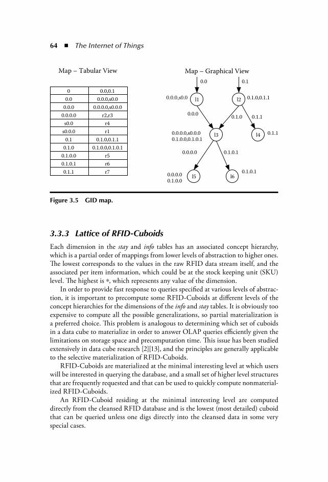
64 The Internet of Things
3.3.3 Lattice of RFID-CuboidsEach dimension in the stay and info tables has an associated concept hierarchy,which is a partial order of mappings from lower levels of abstraction to higher ones.The lowest corresponds to the values in the raw RFID data stream itself, and theassociated per item information, which could be at the stock keeping unit (SKU)level. The highest is , which represents any value of the dimension.
In order to provide fast response to queries specified at various levels of abstrac-tion, it is important to precompute some RFID-Cuboids at different levels of theconcept hierarchies for the dimensions of the info and stay tables. It is obviously tooexpensive to compute all the possible generalizations, so partial materialization isa preferred choice. This problem is analogous to determining which set of cuboidsin a data cube to materialize in order to answer OLAP queries efficiently given thelimitations on storage space and precomputation time. This issue has been studiedextensively in data cube research [2][13], and the principles are generally applicableto the selective materialization of RFID-Cuboids.
RFID-Cuboids are materialized at the minimal interesting level at which userswill be interested in querying the database, and a small set of higher level structuresthat are frequently requested and that can be used to quickly compute nonmaterial-ized RFID-Cuboids.
An RFID-Cuboid residing at the minimal interesting level are computeddirectly from the cleansed RFID database and is the lowest (most detailed) cuboidthat can be queried unless one digs directly into the cleansed data in some veryspecial cases.
l1
0.0
l2
l3
0.0.0
0.1
0.1.0
l4
0.1.1
l5 l6
0.1.0,0.1.1
0.0.0.0
0.0.0.00.1.0.0
0.1.0.1
0.0.0.0,s0.0.00.1.0.0,0.1.0.1
0.1.1
0.1.0.1
Map – Tabular View Map – Graphical View
0 0.0,0.1
0.0 0.0.0,s0.0
0.0.0 0.0.0.0,s0.0.0
0.0.0.0 r2,r3
s0.0 r4
s0.0.0 r1
0.1 0.1.0,0.1.1
0.1.0 0.1.0.0,0.1.0.1
0.1.0.0 r5
0.1.0.1 r6
0.1.1 r7
Figure 3.5 GID map.
RFID Data Warehousing and Analysis 65
3.4 Construction of an RFID WarehouseIn order to construct the RFID-Cuboid, as described in the chapter, one needs a com-pact data structure that does the following efficiently: (1) assign path-dependent labelsto the gids, (2) minimize the number of output stay records while computing aggregatesthat preserve the path-like nature of the data, and (3) identify path segments that canbe collapsed. Such structure is a tree representation of the path database, where eachnode in the tree represents a path stage; and all common path prefixes in the databaseshare the same branch in the tree. The tree is traversed in breath-first order, that is, wevisit nodes level by level to assign path-dependent labels to the nodes. The minimumnumber of output stay records can be quickly determined by aggregating the measuresof all the items that share the same branch in the tree. And path segments can be col-lapsed by simply merging parent/child nodes that correspond to the same location, orby merging uninteresting locations. Additionally, the tree can be constructed by doinga single scan of the cleansed RFID database, and it can be discarded after one hasmaterialized the output info, stay, and map tables.
The most common implementation of the group-by operator, which would sortthe input records on location, time_in, and time_out, and generate a list of RFIDtags that share the same values on these dimensions, would fail in generating theRFID-Cuboid in an efficient manner. The problem with this approach is that oneloses the ability to determine which of the items that share the same location, time_in, and time_out values can actually have their measures aggregated into a singlevalue. The reason is that one cannot quickly determine which subset of all the itemsfollowed the same path throughout the system without doing an unmanageablenumber of item list intersections. For this same reason, one cannot easily constructthe map table, assign path-dependent labels to the gids, or determine if two differ-ent records can be collapsed into one.
Algorithm 1 summarizes the method for constructing an RFID-Cuboid fromthe cleansed RFID database. It takes as input the clean stay records S, the inforecords I describing each item, and the level of abstraction for each dimension L.The output of the algorithm is an RFID-Cuboid represented by the stay, info, andmap tables aggregated at the desired abstraction level.
First, the information table is aggregated to the level of abstraction specifiedby L. This is done by using a regular cubing algorithm. Second, the BuildPathTreeprocedure is called (Algorithm 2), which constructs a tree for the paths traveledby items in the cleansed database. The paths that have the same branch in the treeshare the same path prefix. Each node in the tree is of the form (location, time_in, time_out, measure_list, children_list) where time_in is the time at which the itemsentered location, time_out the time at which they left, measure_list contains thestay measures (from the parent’s location to this node’s location) for every item thatstayed at the node, and children_list is a list of nodes where the items in the nodemoved next. All processing from this point on in the algorithm will be done usingthe tree, which is called path_tree.

66 The Internet of Things
Third, the algorithm merges consecutive nodes in the tree that correspond tothe same location. This is done because it is possible for two distinct locations tobe aggregated to the same higher level location. This step achieves compression bycollapsing paths to the given abstraction level. Fourth, gids are generated for thenodes in the tree. This is done in the breath-first order, and each node receives aunique id that is appended to the gid of its parent node. This naming scheme isused to speed up the computation of linked stay records for query processing. Fifth,the measure_list at each node is compacted to one aggregate measure for each groupof RFID tags that share the same leaf (descendant from the node) and info record.Further compression is done when several leaves share the same measure.
Finally, the algorithm traverses the tree, generating the new stay table: Eachnode generates as many records as the number of distinct measures it contains. It ispossible for multiple nodes to share the same stay record if they share all the attri-butes and measures. For example, if there are two nodes in the path_tree that havethe same location, time_in, time_out, and measures, we generate a single stay recordthat has two gids, one for each node.
Table 3.3 presents the stay table that would be generated by running Algorithm1 on the cleansed data from Table 3.2. We have now gone from 188 records in theraw data, to 17 in the cleansed data, and then to 7 in the compressed data.
3.4.1 Construction of Higher Level RFID-CUBOIDs from Lower Level Ones
Once the minimum abstraction level RFID-Cuboid has been constructed, it ispossible to gain efficiency by constructing higher level RFID-Cuboids startingfrom the existing RFID-Cuboid instead of directly from the cleansed RFID data.This can be accomplished by running Algorithm 1 with the stay and info tablesof the lower level RFID-Cuboid as input, and using the map table of the inputRFID-Cuboid to expand each gid to the EPCs it points to. The benefit of such anapproach is that the input stay and info tables can be significantly smaller than thecleansed tables, thus, greatly gaining in space and time efficiency.
Table 3.3 Output Stay Recordsgid loc t1 t2 count measure
0.0 l1 t1 t10 4 9
0.1 l2 t1 t8 3 7
0.0.0 l3 t20 t30 3 9
0.1.0 l3 t20 t30 2 19
0.1.1 l4 t10 t20 1 19
0.0.0.0,0.1.0.0 l5 t40 t60 3 19
0.1.0.1 l6 t35 t50 1 14

RFID Data Warehousing and Analysis 67
Algorithm 1: BuildCuboid
5inInput: Stay records S, Information records I, aggregation level LOutput: RFID-CuboidMethod:
1: I’ aggregate I to L2: path_tree BuildPathTree (S, L)3: Merge consecutive nodes with the same location in the path_tree4: Traverse path_tree in the breath-first order and assign gid to each node
(gid parent.gid ‘.’ unique id) where the parent/children gid relation in the path_tree defines the output MAP
5: Compute aggregate measures for each node, one per group of items with the same information record and in the same leaf
6: Create S’ by traversing path_tree in the breath-first order and generating stay records for each node (multiple nodes can contribute to the same stay record)
7: Output MAP, S’, and I’
Observation: Given a cleansed stay and info input tables, the RFID-Cuboidstructure has the following properties:
1. Construction cost: The RFID-Cuboid can be constructed by doing a singlesequential scan on the cleansed stay table.
2. Completeness: The RFID-Cuboid contains sufficient information to recon-struct the original RFID database aggregated at abstraction level L.
3. Compactness: The number of records in the output stay and info tables is nolarger than the number of records in the input stay and info tables, respectively.
Rationale: The first property has been shown in the RFID-Cuboid construc-tion algorithm. The completeness property can be proved by using the map tableto expand the gids for each stay record to get the original data. The compactnessproperty is proved noticing that Algorithm 1 emits, at most, one output record perdistinct measure per node, and the number of distinct measures in a node is limitedby the number of input stay records. The size of the output info table, by definitionof the group-by operation, is bound by the size of the input info table.
Table 3.4 Data Set Parameters(s1, ,sk) Path Bulkiness
k Average path lengthP Number of productsN Number of cleansed RFID records

68 The Internet of Things
Algorithm 2: BuildPathTree
Input: Stay S, aggregation level LOutput: path_treeMethod:
1: root new node2: for each record s in S do3: s’ aggregate s to level L4: parent lookup node for s’.rfid5: if parent NULL then6: parent root7: end if8: node lookup s’.rfid in parent’s children9: if node NULL then
10: node new node11: node.loc s.loc12: node.t1 s.t113: node.t2 s.t214: add node to parent’s children15: end if16: node.measure_list s’.gid,s’.measure17: end for18: return root
3.5 Query ProcessingA very important aspect of the RFID warehouse is the efficient handling of tradi-tional OLAP operations, i.e., drill-down, roll-up, slice, and dice. These operationsallow a data analyst to navigate the lattice of RFID-Cuboids. The warehouse alsoneeds to support a new type of operation, path selection, which is unique to RFIDdata sets and is necessary to compute path dependent aggregates.
3.5.1 OLAPTraditionally a data cube is navigated by the usage of four operations:
3.5.1.1 Rollup
The rollup operation performs aggregation on a data cube, either by climbing up aconcept hierarchy for a dimension or by dimension reduction. For example, assumethat the location has the concept hierarchy location locale location category,time has the hierarchy second hour day, and product has the hierarchy EPC
RFID Data Warehousing and Analysis 69
SKU. Now, assume that one is looking at the stay table at the level of locale, hourand at the info table at the level of EPC, i.e., for each EPC, one aggregates stay withthe same time_in, and time_out at the hour level, and the same location at the localelevel. One can rollup to a higher abstraction level, such as, location, category, dayand SKU where each stay and info perform coarser aggregation.
The rollup operation is implemented in the RFID warehouse by retrieving therelevant RFID-Cuboid, or if the cuboid has not been materialized by computing iton the fly from the closest materialized RFID-Cuboid that is at a lower abstractionlevel than the needed one.
3.5.1.2 Drill Down
This operation is the inverse of rollup, during drill down one moves to more detaileddata by climbing down a concept hierarchy or by adding new dimensions. Using theabove example, we may drill down from locale, day, , SKU to locale, second , EPC.
The drill-down operation is implemented in the RFID warehouse in the samemanner as the rollup one. We just retrieve the relevant RFID-Cuboid or material-ize it on the fly from the available ones. One important aspect that needs to bementioned, is that when the minimum abstraction level RFID-Cuboid has beenreached through drill-down operations, if users want to go to even more detaileddata, they can retrieve the paths for the EPCs for which more detail is needed. Forexample, even though the lowest level RFID-Cuboid is aggregated at the SKUlevel, a store manager may want to retrieve the concrete EPCs for those perishableitems that have stayed for more than three weeks in the refrigerator.
3.5.1.3 Slice and Dice
These operations perform selection on one or more dimensions of the RFID-Cuboid. For example, after retrieving a certain RFID-Cuboid, one may want tolook only at those stay records that correspond to electronic goods, for the North-east region.
The slice and dice operations can be implemented quite efficiently by usingrelational query execution and optimization techniques. An example of the diceoperation could be: “Give me the average time that milk stays at the shelf in storeS1 in Illinois.” This can be answered by the relational expression:
stay.location shelf ’,info.product milk’ (stay gid info).
3.5.2 Path Query ProcessingPath queries, which ask about information related to the structure of object traversalpaths, are unique to the RFID warehouse because the concept of object movements
70 The Internet of Things
is not modeled in traditional data warehouses. It is essential to allow users to inquireabout an aggregate measure computed based on a predefined sequence of locations(path). One such example could be: “What is the average time for milk to travelfrom farms to stores in Illinois?”
Queries on the paths traveled by items are fundamental to many RFID applica-tions and will be the building block on top of which more complex data-miningoperators can be implemented. We will illustrate this point with two real examples.First, the United States government is currently in the process of requiring thecontainers arriving into the country by ship to carry an RFID tag. The informa-tion can be used to determine if the path traveled by a given container has deviatedfrom its historic path. This application may need to first execute a path-selectionquery across different time periods, and then use outlier detection and cluster-ing to analyze the relevant paths. Second, plane manufacturers are planning totag airplane parts to better record maintenance operations on each part. Again,using path selection queries one could easily associate a commonly defective partwith a path that includes a certain set of suppliers who provide raw material for itsconstruction and are likely the sources of the defect. This task may need frequentitem set counting and association mining on the relevant paths. These examplesshow that path selection can be crucial to successful RFID data analysis and min-ing, and it is important to design good data structures and algorithms for efficientimplementation.
More formally, a path selection query is of the form:
q cinfo, ( c1stagei, , ck
stagek)
where cinfo means the selection on the info table based on condition c, and cistagei
means the selection based on condition ci on the stay table stagei. The result of a pathselection query is a set of paths whose stages match the stage conditions in the cor-rect order (possibly with gaps), and whose items match the condition c. The queryexpression for the example path query presented above is c product “milk” ,c1 location “ farm” , and c2 location “store” . We can compute aggregatemeasures on the results of a path selection query, e.g., for the example query, theaggregate measure would be average time.
Algorithm 3 illustrates the process of selecting the gids matching a given query.It first selects the gids for the stay records that match the conditions for the initialand final stages of the query expression. For example, gstart may look like 1.2, 8.3.1,3.4 , and gend may look like 1.2.4.3, 4.3, 3.4.3 . Then it computes the pairs of gidsfrom gstart that are a prefix of a gid in gend. Continuing with the example, one getsthe pairs (1.2, 1.2.4.3), (3.4, 3.4.3) . For each pair the algorithm then retrieves allthe stay records. The pair (1.2, 1.2.4.3) would require the retrieval of all stay recordsthat include gids 1.2, 1.2.4, and 1.2.4.3. Finally, a verification phase is conductedwhere we check that each retrieved record matches the selection conditions for eachstagei and for info, and add those paths to the answer set.

RFID Data Warehousing and Analysis 71
If statistics on query selectivity are available, it may be possible to find a betteroptimized query execution plan than that presented in Algorithm 3. If one has asequence of stages (stagei, , stagek), one could retrieve the records for the mostselective stages, in addition to retrieving the stay records for stagei and stagek, inorder to further prune the search space.
Algorithm 3: PathSelection
Input: q cinfo, ( c1stagei, , ck
stagek) , RFID warehouseOutput: the paths that match query conditions, qMethod:
1: gstart select gids of stay records matching the condition at stage1
2: gend select gids of stay records matching the condition at stagek and that for info
3: for every pair of gids (s, e) in gstart, gend such that s is a prefix of e do4: path retrieve stay records for all gids from s to e5: if the stay records in path match conditions for info and for the remaining
stages then6: answer answer path7: end if8: end for9: return answer
Analysis: Algorithm 3 can be executed efficiently if the following indices areavailable. A one-dimensional index for each dimension of the stay table, a one-dimensional index on the gid dimension of the map table, and a one-dimensionalindex on the EPC dimension of the info table. The computation of gstart and gend
can be done by retrieving the records that match each condition at stagei and stagek,and intersecting the results. Verification of the condition cinfo is done by usingthe map table to retrieve the base gids for each gid in stagek that has as prefix a gidin stagei. The info record for each base_gid can be retrieve efficiently by using theEPC index on the info table. When no indices are available, algorithm 3 can still beexecuted efficiently by performing a single scan of the stay and info tables.
3.6 Performance StudyIn this section, a thorough performance analysis of the RFID warehouse is con-ducted. All experiments were implemented using C and were conducted on anIntel Xeon 2.5 GHz (512 kb L2 cache) system with 3 Gb of RAM. The system ranRed Hat Linux with the 2.4.21 kernel and gcc 3.2.3.

72 The Internet of Things
3.6.1 Data SynthesisThe RFID databases in the experiments were generated using a tree model forobject movements. Each node in the tree represents a set of items in a location,and an edge represents a movement of objects between locations. Items at locationsnear the root of the tree move in larger groups, while items near the leaves move insmaller groups. The size of the groups at each level of the tree define the bulkiness,
(si, s2, , sk), where si is the number of objects that stay and move together atlevel i of the tree. By making si sj for i j, we create the effect of items moving inlarger groups near the factory and distribution centers, and smaller groups at thestore level. The datasets for the experiments were generated by randomly construct-ing a set of trees with a given level of bulkiness, and generating the cleansed RFIDrecords corresponding to the item movements indicated by the edges in the tree.
As a notational convenience, we use the following symbols to denote certaindataset parameters.
3.6.2 RFID-Cuboid CompressionThe RFID-Cuboids form the basis for future query processing and analysis. Asmentioned previously, the advantage of these data structures is that they aggregateand collapse many records in the cleansed RFID database. Here, we examine theeffects of this compression on different data sets. We compare two different com-pression strategies, both use the stay and info tables, but one uses the map table asdescribed in section 3.3.2.3, whereas the other uses a tag list to record the tags ateach stay record (nomap).
Figure 3.6 illustrates the size of the cleansed RFID database (raw) comparedwith the map and nomap RFID-Cuboids. The datasets contain 1,000 distinct prod-ucts, traveling in groups of 500, 150, 40, 8, and 1 through 5 path stages, and500,000 to 10 million cleansed RFID records. The RFID-Cuboid is computed atthe same level of abstraction of the cleansed RFID data and, thus, the compression
0
50
100
150
200
250
300
350
10510.50.1Input Stay Records (millions)
Siz
e (
Mb
yte
s)
clean
nomap
map
Figure 3.6 Compression versus cleansed data size: 1000, (500, 150, 40, 8, 1), 5.
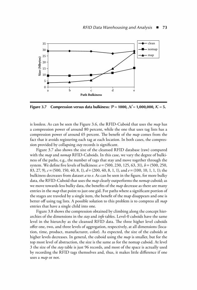
RFID Data Warehousing and Analysis 73
is lossless. As can be seen the Figure 3.6, the RFID-Cuboid that uses the map hasa compression power of around 80 percent, while the one that uses tag lists has acompression power of around 65 percent. The benefit of the map comes from thefact that it avoids registering each tag at each location. In both cases, the compres-sion provided by collapsing stay records is significant.
Figure 3.7 also shows the size of the cleansed RFID database (raw) comparedwith the map and nomap RFID-Cuboids. In this case, we vary the degree of bulki-ness of the paths, e.g., the number of tags that stay and move together through thesystem. We define five levels of bulkiness: a (500, 230, 125, 63, 31), b (500, 250,83, 27, 9), c (500, 150, 40, 8, 1), d (200, 40, 8, 1, 1), and e (100, 10, 1, 1, 1); thebulkiness decreases from dataset a to e. As can be seen in the figure, for more bulkydata, the RFID-Cuboid that uses the map clearly outperforms the nomap cuboid; aswe move towards less bulky data, the benefits of the map decrease as there are manyentries in the map that point to just one gid. For paths where a significant portion ofthe stages are traveled by a single item, the benefit of the map disappears and one is better off using tag lists. A possible solution to this problem is to compress all mapentries that have a single child into one.
Figure 3.8 shows the compression obtained by climbing along the concept hier-archies of the dimensions in the stay and info tables. Level-0 cuboids have the samelevel in the hierarchy as the cleansed RFID data. The three higher level cuboidsoffer one, two, and three levels of aggregation, respectively, at all dimensions (loca-tion, time, product, manufacturer, color). As expected, the size of the cuboids athigher levels decreases. In general, the cuboid using the map is smaller, but for thetop most level of abstraction, the size is the same as for the nomap cuboid. At level3 the size of the stay table is just 96 records, and most of the space is actually usedby recording the RFID tags themselves and, thus, it makes little difference if oneuses a map or not.
0
5
10
15
20
25
30
35
edcba
Path Bulkiness
Siz
e (
Mb
yte
s)clean
nomap
map
Figure 3.7 Compression versus data bulkiness: 1000, 1,000,000, 5.
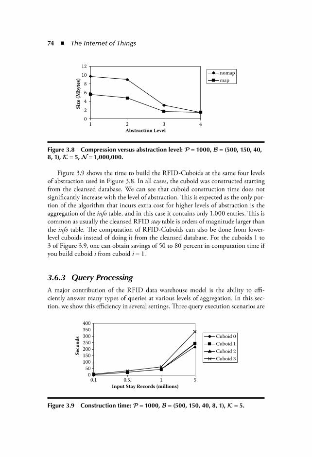
74 The Internet of Things
Figure 3.9 shows the time to build the RFID-Cuboids at the same four levelsof abstraction used in Figure 3.8. In all cases, the cuboid was constructed startingfrom the cleansed database. We can see that cuboid construction time does notsignificantly increase with the level of abstraction. This is expected as the only por-tion of the algorithm that incurs extra cost for higher levels of abstraction is theaggregation of the info table, and in this case it contains only 1,000 entries. This iscommon as usually the cleansed RFID stay table is orders of magnitude larger thanthe info table. The computation of RFID-Cuboids can also be done from lower-level cuboids instead of doing it from the cleansed database. For the cuboids 1 to3 of Figure 3.9, one can obtain savings of 50 to 80 percent in computation time ifyou build cuboid i from cuboid i 1.
3.6.3 Query ProcessingA major contribution of the RFID data warehouse model is the ability to effi-ciently answer many types of queries at various levels of aggregation. In this sec-tion, we show this efficiency in several settings. Three query execution scenarios are
nomap
map
0
2
4
6
8
10
12
Siz
e (
Mb
yte
s)
4321
Abstraction Level
Figure 3.8 Compression versus abstraction level: 1000, (500, 150, 40, 8, 1), 5, 1,000,000.
Input Stay Records (millions)
Se
con
ds
510.5.0.10
50
100
150
200
250
300
350
400
Cuboid 0
Cuboid 1
Cuboid 2
Cuboid 3
Figure 3.9 Construction time: 1000, (500, 150, 40, 8, 1), 5.
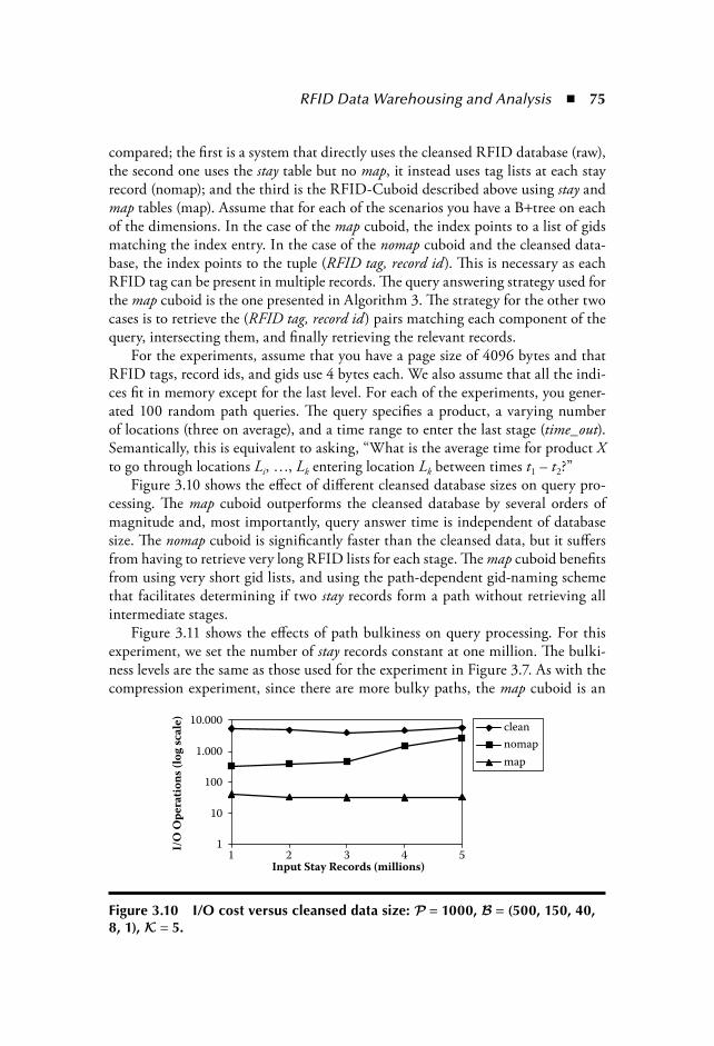
RFID Data Warehousing and Analysis 75
compared; the first is a system that directly uses the cleansed RFID database (raw),the second one uses the stay table but no map, it instead uses tag lists at each stayrecord (nomap); and the third is the RFID-Cuboid described above using stay andmap tables (map). Assume that for each of the scenarios you have a B tree on eachof the dimensions. In the case of the map cuboid, the index points to a list of gidsmatching the index entry. In the case of the nomap cuboid and the cleansed data-base, the index points to the tuple (RFID tag, record id). This is necessary as eachRFID tag can be present in multiple records. The query answering strategy used forthe map cuboid is the one presented in Algorithm 3. The strategy for the other twocases is to retrieve the (RFID tag, record id) pairs matching each component of thequery, intersecting them, and finally retrieving the relevant records.
For the experiments, assume that you have a page size of 4096 bytes and thatRFID tags, record ids, and gids use 4 bytes each. We also assume that all the indi-ces fit in memory except for the last level. For each of the experiments, you gener-ated 100 random path queries. The query specifies a product, a varying numberof locations (three on average), and a time range to enter the last stage (time_out).Semantically, this is equivalent to asking, “What is the average time for product Xto go through locations Li, , Lk entering location Lk between times t1 – t2?”
Figure 3.10 shows the effect of different cleansed database sizes on query pro-cessing. The map cuboid outperforms the cleansed database by several orders ofmagnitude and, most importantly, query answer time is independent of databasesize. The nomap cuboid is significantly faster than the cleansed data, but it suffersfrom having to retrieve very long RFID lists for each stage. The map cuboid benefitsfrom using very short gid lists, and using the path-dependent gid-naming schemethat facilitates determining if two stay records form a path without retrieving allintermediate stages.
Figure 3.11 shows the effects of path bulkiness on query processing. For thisexperiment, we set the number of stay records constant at one million. The bulki-ness levels are the same as those used for the experiment in Figure 3.7. As with thecompression experiment, since there are more bulky paths, the map cuboid is an
Input Stay Records (millions)
I/O
Op
era
tio
ns
(lo
g s
cale
)
1
10
100
1.000
10.000clean
nomap
map
54321
Figure 3.10 I/O cost versus cleansed data size: 1000, (500, 150, 40, 8, 1), 5.
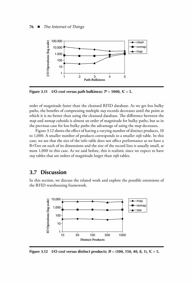
76 The Internet of Things
order of magnitude faster than the cleansed RFID database. As we get less bulkypaths, the benefits of compressing multiple stay records decreases until the point atwhich it is no better than using the cleansed database. The difference between themap and nomap cuboids is almost an order of magnitude for bulky paths, but as inthe previous case for less bulky paths the advantage of using the map decreases.
Figure 3.12 shows the effect of having a varying number of distinct products, 10to 1,000. A smaller number of products corresponds to a smaller info table. In thiscase, we see that the size of the info table does not affect performance as we have aB Tree on each of its dimensions and the size of the record lists is usually small, atmost 1,000 in this case. As we said before, this is realistic since we expect to havestay tables that are orders of magnitude larger than info tables.
3.7 DiscussionIn this section, we discuss the related work and explore the possible extensions ofthe RFID warehousing framework.
1
10
100
1.000
10.000
100.000
54321Path Bulkiness
I/O
Op
era
tio
ns
(lo
g s
cale
)
cleannomapmap
Figure 3.11 I/O cost versus path bulkiness: 1000, 5.
Distinct Products
100010 50 100 5001
10
100
1,000
10,000
IO O
per
ati
on
s (l
og
sca
le)
mapnomapraw
Figure 3.12 I/O cost versus distinct products: (500, 150, 40, 8, 1), 5.

RFID Data Warehousing and Analysis 77
3.7.1 Related WorkRFID technology has been extensively studied from mostly two distinct areas: theelectronics and radio communication technologies required to construct readersand tags [4], and the software architecture required to securely collect and manageonline information related to tags [17][18].
More recently a third line of research dealing with mining of RFID data hasemerged. Chawathe et al. [3] introduced the idea of creating a warehouse for RFID data,but do not go into the data structure or algorithmic details. Gonzalez et al. (2006c) [10]present a concrete RFID warehouse design and most of the contents of this chapter arebased on their design. Gonzalez et al. (2006a) [8] present the idea of the FlowCube,which is a warehouse similar to the one introduced in [10], but where each cell stores aFlowGraph [9], which is a probabilistic workflow model that captures the major move-ment trends and significant deviations for items aggregated in the cell.
Cleaning of RFID data sets is another problem related to warehouse construction,as one relies on clean data to build a high-quality model. There have been extensivestudies in the design of communication protocols, at the hardware level, which arerobust to interference and collisions [7][14]. At the software level, the use of smooth-ing windows has been proposed as a method to reduce false negatives. Floerkemeierand Lampe [5] proposed the fixed-window smoothing. Jeffrey et al. (2006a) [15]proposed a variable-window smoothing that adapts window size dynamically accord-ing to tag detection rates, by using a binomial model of tag readings. Jeffrey et al.(2006b) [16] present a framework to clean RFID data streams by applying a seriesof filters, but do not go into the details of filter design. Gonzalez et al. (2007) [11]define a cost-conscious cleaning framework that is designed to handle the efficientand accurate cleaning of large RFID datasets; the idea of the framework is to con-struct a cleaning plan that applies inexpensive cleaning methods whenever possible,and more expensive cleaning techniques only when absolutely necessary.
An RFID data warehouse shares many common principles with the traditionaldata cube [1][2][12]. They both aggregate data at different levels of abstraction inmultidimensional space. Since each dimension has an associated concept hierarchy,both can be (at least partially) modeled by a Star schema. The problem of decidingwhich RFID-Cuboids to construct in order to provide efficient answers to a vari-ety of queries specified at different abstraction levels is analogous to the problemof partial data cube materialization studied in [13][19]. However, RFID-Cuboiddiffers from a traditional data cube in that it also models object transitions in mul-tidimensional space, which is crucial to answering queries related to object move-ments/transitions as demonstrated in this analysis.
3.7.2 Open IssuesBelow is a discussion of methods for incremental update in the RFID warehouse,construction of fading RFID model, and its linkage with mining RFID data.

78 The Internet of Things
3.7.2.1 Incremental Update
Incremental update is crucial to RFID applications. A warehouse will receive con-stant updates as new tags enter the system and objects move to new locations.Algorithm 1 can be applied only to the new data to generate new stay and map tables(users need to initialize the gid naming as to not generate duplicates with the exist-ing map). The updated cuboid will be the union of the old stay and map tables withthe new ones. The main reason that we can just run the algorithm in the new datawithout worrying about the old data is that the updates are only for item move-ments with higher timestamps than we already have, so they will form new nodesin the path tree.
3.7.2.2 Construction of a Fading RFID Warehouse Model
In most situations, the more remote in time or distance the data is, the less inter-est a user would have to study it in detail. For example, one may not be interestedin the detailed tag movements among shelves if the data is years old, or thousandsof miles away, or not in the same sector (e.g., manufacturer versus store manager).This will relieve the burden of storing the enormous size of historical or remote orunrelated RFID databases.
The RFID warehouse can be easily adapted to a fading model where remote his-torical or distantly located data can be stored with low resolution (i.e., not retain-ing such data at a low abstraction level). This can be done incrementally by furthersummarizing data being faded at an abstraction level higher than the recent andclose-by data or by simply tossing some low-level cuboid and raising the level of thecorresponding minimum abstraction level RFID-Cuboid for such data.
For example, one could use the following fading strategy: Summarize data forthe last 30 days at the hour level, for the last 12 months at the day level, and for evenolder data at the week level. The architecture of the RFID warehouse is very wellsuited for such summarization schemes.
3.7.2.3 Data Mining in the RFID Warehouse
The RFID warehouse model facilitates efficient data mining since the data in themodel is well structured, aggregated, and organized. Take the frequent itemset min-ing as an example. One can easily mine frequent itemsets at high abstraction levelssince such data is already aggregated with count and other measures computed. TheApriori pruning can be used to prune the search along the infrequent high-levelitemsets. Efficient methods, such as progressive deepening, can be further exploredto reduce the search space. For example, if dairy products and meat are not soldtogether frequently, there is no need to drill down to see whether milk and beef willbe sold together frequently. The RFID warehouse model naturally facilitates level-wise pruning based on its multilevel structure and levelwise precomputation.

RFID Data Warehousing and Analysis 79
3.7.2.4 Warehousing Scattered Movement Data
Notice that the data model presented in this chapter and the methods for ware-house construction and query analysis are based on the assumption that RFID datatends to move together in bulky mode, especially at the early stage. This fits a goodnumber of RFID applications, such as supply chain management. However, thereare also other applications where RFID data may not have such characteristics. Forexample, tracking of cars on a road network or people in a building may exhibitindividual movements that cannot be compressed through the use of generalizedidentifiers. We believe that further research is needed to construct efficient modelsfor such applications.
3.8 ConclusionsThis chapter has introduced a novel model for warehousing RFID data. The designallows high-level analysis to be performed efficiently and flexibly in multidimen-sional space. The model is composed of a hierarchy of highly compact summaries(RFID-Cuboids) of the RFID data aggregated at different abstraction levels wheredata analysis can take place. Each cuboid records tag movements in the stay, info,and map tables that take advantage of the fact that individual tags tend to move andstay together (especially at higher abstraction levels) to collapse multiple movementsinto a single record without loss of information. The performance study shows thatthe size of RFID-Cuboids at interesting abstraction levels can be orders of magni-tude smaller than the original RFID databases and can be constructed efficiently.Moreover, the empirical evaluation highlights the power of the data structures andalgorithms in efficient answering of a wide range of RFID queries, especially thoserelated to object transitions.
The model in this chapter focuses on efficient data warehousing and OLAP-styled analysis of RFID data. Efficient methods for a multitude of other data miningproblems for the RFID data (e.g., trend analysis, outlier detection, path clustering)remain open and should be a promising line of future research.
References [1] S. Agarwal,R. Agrawal,P.M.Deshpande,A. Gupta,J.F.Naughton,R. Ramakrishnan,
and S. Sarawagi. On the computation of multidimensional aggregates. In Proc. 1996 Int. Conf. Very Large Data Bases (VLDB’96), Bombay, India, 1996.
[2] S. Chaudhuri and U. Dayal. An overview of data warehousing and OLAP technol-ogy. SIGMOD Record, 26: 65–74, Toronto, Canada, 1994.
[3] S. Chawathe, V. Krishnamurthy, S. Ramachandran, and S. Sarma. ManagingRFID data. In Proc. Intl. Conf. on Very Large Databases (VLDB’04).
[4] K. Finkenzeller. RFID Handbook: Fundamentals and Applications in Contactless Smart Cards and Identification. John Wiley & Sons, 2003.

80 The Internet of Things
[5] C. Floerkemeier and M. Lampe. Issues with RFID usage in ubiquitous computingapplications. In Pervasive Computing (PERVASIVE) Lecture Notes in Computer Science, 3001: 188–193, 2004.
[6] E. Fredkin. Trie memory. In Communications of the ACM, Vol. 3, Issue 9, 490–499,September 1960.
[7] “EPCglobal Inc, EPC radio-frequency identity protocols class-1 generation-2 UHFRFID procol for communications at 860 MHz to 960 MHz.” http://www.epcglobalinc.org/standards_technology/EPCglobal2UHFRFIDProtocolV109122005.pdf (2003).
[8] H. Gonzalez, J. Han, and X. Li. Flowcube: Constructuing RFID flowcubes formultidimensional analysis of commodity flows. In Proc. 2006 Int. Conf. Very Large Data Bases (VLDB’06), Seoul, Korea, September 2006a.
[9] H. Gonzalez, J. Han, and X. Li. Mining compressed commodity workflowsfrom massive RFID data sets. In Proc. 2006 Conf. on Information and Knowledge Management (CIKM’06), Arlington, VA, November 2006b.
[10] H. Gonzalez, J. Han, X. Li, and D. Klabjan. Warehousing and analysis of massiveRFID data sets. In Proc. 2006 Int. Conf. Data Engineering (ICDE’06), Atlanta,GA, April 2006c.
[11] H. Gonzalez, J. Han, and X. Shen. Cost-conscious cleaning of massive RFID datasets.In Proc. 2007 Int. Conf. Data Engineering (ICDE’07), Istanbul, Turkey, April 2007.
[12] J. Gray, S. Chaudhuri, A. Bosworth, A. Layman, D. Reichart, M. Venkatrao, F.Pellow, and H. Pirahesh. Data cube: A relational aggregation operator general-izing group-by, cross-tab and sub-totals. Data Mining and Knowledge Discovery,1: 29–54, 1997.
[13] V. Harinarayan, A. Rajaraman, and J.D. Ullman. Implementing data cubes effi-ciently. In Proc. 1996 ACM-SIGMOD Int. Conf. Management of Data (SIGMOD’96),Montreal, Canada, 1996.
[14] “MIT Auto-ID Center, 13.56 MHz ism band class 1 radio frequency identifica-tion tag interface specification. Technical report. http://www.epcglobalinc.org/standards_technology/Secure/v1.0/VHF-class0.pdf (2003).
[15] S.R. Jeffrey, M. Garofalakis, and M.J. Franklin. Adaptive cleaning for RFID datastreams. In Proc. 2006 Int. Conf. Very Large Data Bases (VLDB’06), Seoul, Korea,September 2006a.
[16] S.R. Jeffrey, G. Alonso, M. Franklin, W. Hong, and J. Widom. A pipelined frame-work for online cleaning of sensor data streams. In Proc. 2006 Int. Conf. Data Engineering (ICDE’06), Atlanta, GA, April 2006b.
[17] S. Sarma, D.L. Brock, and K. Ashton. The networked physical world. White paper,MIT Auto-ID Center, http://archive.epcglobalinc.org/publishedresearch/MIT-AUTOID-WH-001.pdf (2000).
[18] S.E. Sarma, S.A. Weis, and D.W. Engels. RFID systems, security & privacy impli-cations. White paper, MIT Auto-ID Center, http://archive.epcglobalinc.org/publishedresearch/MIT-AUTOID-WH-014.pdf (2002).
[19] A. Shukla, P. Deshpande, and J.F. Naughton. Materialized view selection for mul-tidimensional datasets. In Proc. 1998 Int. Conf. Very Large Data Bases (VLDB’98),New York, 1998.

81
Chapter 4
RFID Data Management: Issues, Solutions, and Directions
Quan Z. Sheng, Kerry L. Taylor, Zakaria Maamar, and Paul Brebner
Contents4.1 Introduction ..............................................................................................824.2 Overview of RFID Frameworks................................................................ 84
4.2.1 Architecture of an RFID System.................................................... 844.2.2 Dimensions for RFID Data Processing...........................................854.2.3 Dimensions for RFID Data Integration..........................................86
4.3 State-of-the-Art Technologies for RFID Data Management ......................884.3.1 Siemens RFID Middleware ............................................................884.3.2 ESP.................................................................................................894.3.3 Oracle’s EPC Bitmap ..................................................................... 904.3.4 RFID Warehouse........................................................................... 904.3.5 Evaluations and Open Issues...........................................................91
4.4 RFID Integration Platforms.......................................................................934.4.1 UCLA WinRFID ...........................................................................934.4.2 Siemens RFID Middleware ............................................................944.4.3 SAP Auto-ID Infrastructure ...........................................................944.4.4 Sun Java System RFID Software.....................................................95

82 The Internet of Things
Radio Frequency IDentification (RFID) technology has existed for the past50 years. However, only in recent years, has RFID technology moved from obscu-rity into mainstream applications for automatic identification. The driving forcebehind this major shift is the increasing affordability of RFID tags, the convergenceof industrial standards, the added value offered to applications, and the efforts thatEPCglobal and industry giants like Wal-Mart have put into the use of RFID tech-nology. While RFID technology provides promising benefits, such as inventory vis-ibility and business process automation, several significant challenges, such as dataprocessing and management, integration architecture design, security, and privacyneed to be seriously addressed before these benefits can be fully realized. In thischapter, we survey the main techniques for RFID data processing and integration,a central concern in applying RFID in real-world applications, and propose a setof criteria for assessing the existing RFID techniques and products. Open researchissues for RFID data processing and integration are also discussed.
4.1 IntroductionUniquely identifying individual objects is a powerful capability, which is essentialto many aspects of modern life, such as manufacturing, distribution logistics, accesscontrol, and fighting terrorism. Today’s identification systems consist of identifyingmarkings (e.g., barcodes, photos, signatures) and ways to read them (e.g., scan-ners, photo detectors, humans). RFID is a wireless communication technology thatis useful in identifying objects accurately [19,40,68]. RFID uses radio-frequencywaves to transfer data between tagged objects and readers without line of sight,providing an excellent support for automatic identification.
Although RFID has been around for more than a half century [37], it is onlyin recent years that this technology has been gaining significant momentum due tothe convergence of lower cost and increased capabilities of RFID tags. Currently,RFID is emerging as an important technology for revolutionizing a wide range ofapplications, including supply chain management, retail, aircraft maintenance, anti-counterfeiting, baggage handling, and healthcare [7,40,55,69]. It also heralds theemergence of inexpensive and highly effective pervasive computers that will havedramatic impacts on individuals, organizations, and societies [59]. Many organi-zations are planning or have already exploited RFID in their main operations totake advantage of the potential of more automation, efficient business processes, and
4.4.5 EPCglobal Network........................................................................954.4.6 Other Platforms..............................................................................964.4.7 Evaluations and Open Issues...........................................................97
4.5 Conclusion...............................................................................................101Reference ..........................................................................................................101
RFID Data Management: Issues, Solutions, and Directions 83
inventory visibility. For example, a recent news shows that Wal-Mart has reducedout-of-stocks by 30 percent on average after launching its RFID program [33]. Manypredictions agree that RFID will be worth billions of dollars in new investments [3].According to IDTechEx, a leading market research and advisory firm, the RFIDmarket will rocket from $2.71 billion in 2006 to $26.23 billion in 2016 [13].
While RFID provides promising benefits in many applications, some significantchallenges need to be overcome before these benefits can be realized. An importantchallenge in RFID applications is data management. This has been a central con-cern because RFID data possess significant characteristics—such as streaming andlarge volume, noisy, spatial and temporal, implicit semantics—that require specialattention [9,65]. The deployment of large-scale RFID applications also offers uniquechallenges in terms of scalability, heterogeneity, manageability, and legacy systems.Last but not least, given the ability of inexpensively tagging and, thus, monitoring alarge number of items (e.g., people), RFID raises some serious security and privacyconcerns that are critical issues in adapting RFID technology [24,43].
Many researchers are currently engaged in developing solutions for these chal-lenges. In this chapter, we present a survey on the main issues and solutions thathinder and boost the exploitation of RFID technology, respectively. The aim of thiswork is to provide a better understanding of the current research issues and activitiesin this field. However, it is worth mentioning that we do not cover, every possibleaspect of RFID technology. For example, hardware research (tags design, readerinterference study) is important for RFID, but is out of the scope of this chapterbecause the focus is on the techniques for using RFID in advanced business applica-tions, such as real-time product tracking and tracing. Although some surveys aboutRFID have been conducted recently (e.g., [2,12,21,34,48,51,69]), they are mostlyfragmented and lack a holistic view of the problem. In particular, the work coveredin those surveys did not specifically focus on RFID data processing and integra-tion. In this chapter, we propose a framework to compare techniques for developingRFID applications. The framework identifies three layers of RFID systems: RFIDhardware, RFID data processing, and RFID data integration. It also proposes a setof dimensions, which are used as a benchmark, to study these RFID solutions.
To the best of our knowledge, this is the first effort that studies the state-of-the-art techniques on RFID data management and application development. Thus,the chapter is valuable to readers looking for a general overview of the topic. It isalso useful to professional RFID users seeking for guidance in the development ofRFID applications.
The remainder of the chapter is organized as follows. In section 4.2, we firstdefine the different layers in generic RFID systems and identify a set of dimensionsfor comparing RFID solutions across these layers. In section 4.3 and section 4.4,we provide a detailed investigation of current proposals for RFID data processingand integration. These approaches and platforms are then evaluated against a set ofdimensions. We also highlight some likely future directions for research and devel-opment. Finally, in section 4.5, is the conclusion.

84 The Internet of Things
4.2 Overview of RFID FrameworksRFID is emerging as a promising technology for a wide range of applications, suchas access control, supply chain management, and healthcare. However, most exist-ing RFID applications are still in their early stages and have been designed in afairly ad-hoc manner. There is no standard for RFID application development asof yet and there is a lack of definitions of requirements that RFID systems mustsatisfy. In this section, we first present a typical architecture of an RFID systemand identify the different layers that make up such a system. We then identify a setof dimensions, which will be used as a benchmark, to study RFID data processingand integration issues in the development of RFID applications.
4.2.1 Architecture of an RFID SystemRFID-enabled applications refer to the use of RFID technology and computerizedsystems (e.g., networking services, databases, Web servers) for achieving advancedbusiness goals like real-time products tracking, automatic warehouse management,just to cite a few [40]. It is of interest to note that deploying an RFID applica-tion by directly hooking RFID readers to backend systems is considered as disas-trous as watering a lawn by hooking a garden hose directly to a fire hydrant [45].An appropriate architecture is the key to the success of RFID applications. Thebuilding blocks in RFID applications are provided through an RFID framework(Figure 4.1). Typically, the purpose of an RFID framework is to enable data tobe: (1) transmitted by a portable device (i.e., an RFID tag), which is read by anRFID reader; (2) processed; and (3) adapted according to the needs of a particularapplication.
Figure 4.1 depicts the main components of a generic RFID system. Interac-tions in such a system occur in three layers: devices, data processing, and dataintegration. The RFID devices layer consists of RFID tags and readers as well asRFID protocols (e.g., ISO 14443, electronic product code (EPC) Class 0 and 1) forreading and writing RFID data. The RFID data processing layer consists of a num-ber of software components for communicating with RFID readers, filtering andcleaning RFID data, and adapting RFID data for high-level applications, includingsemantic filtering and automatic data transformation and aggregation. RFID datacan be formatted using, for example, the Physical Markup Language (PML) [20]and sent to different targets as messages, streams, or other formats via Web services:JMS, HTTP response, or TCP/IP data packets.
The RFID data integration layer is concerned with the applications that exploit RFIDdata, such as supply chain management. RFID data could be both local RFID data andthe one from its business partners, which is typically the case when applications involvemultiple business entities. This requires that the applications understand the semanticsof RFID data that is possibly disparately represented. The objective of interactions at thislayer is to achieve a seamless weaving of RFID data and business processes.

RFID Data Management: Issues, Solutions, and Directions 85
This chapter focuses on the part of the system that lies above the RFID deviceslayer. (Readers are referred to [10,15,19,21,55,67] for more details on physicalaspects related to RFID devices and relevant research problems.)
4.2.2 Dimensions for RFID Data ProcessingRFID data possesses significant characteristics [9,65], that have to be fully consid-ered by RFID data processing approaches. Therefore, the characteristics of RFIDdata are taken as the dimensions for evaluating RFID data processing approaches(i.e., whether or not an approach handles a particular characteristic of RFIDdata).
Despite the diversity of RFID applications, RFID data shares some commonfundamental characteristics:
Inaccurate: While the accuracy of current RFID readers is improving,there are still erroneous readings in RFID systems, such as duplicate reads,missed reads, and ghost reads [14], due to interference, temporary or per-manent malfunction of some components. Therefore, RFID data tends tobe noisy and unreliable.
WarehouseManagement
System
SupplyChainSystem
EnterpriseResourcePlanning
Trading Partner RFID DataIntegration
Network
Reader Reader Reader
Tag Tag Tag Tag TagTag
RFIDDevices
RFID DataProcessing
RFIDDatabase
Enterprise Application Integration
Reader Adapter Reader Adapter
RFID Data Filter
RFID Data Aggregator
RFID Data Adapter
Figure 4.1 Architecture of an RFID system.
86 The Internet of Things
Streaming and large volume: RFID data is quickly and automatically gener-ated. The data volume generated can be enormous. For example, VentureDevelopment Corporation [64] predicts that, when tags are used at theitem level, Wal-Mart will generate around 7 terabytes of data every day.Dynamic and temporal: The RFID data is dynamically generated and asso-ciated with timestamps when the readings are made. All RFID-relatedtransactions are, in fact, associated with time. Temporal information isimportant for tracking and monitoring RFID objects. For example, withtimestamps, it is possible to get the information on how long it takes for anaircraft part to move from the warehouse to the maintenance venue.Location-based: Tagged objects are typically mobile by going through differ-ent locations during their life cycles. For example, in supply chain systems,a product travels among different physical sites, such as manufacturer, dis-tribution center, retailer, and finally customer.Implicit inferences: RFID data always carrys implicit information, such aschanges in states and business processes, and further derived information likeaggregations (e.g., containment relationship among RFID objects). In orderto be applied, RFID data always requires the context of other information,such as business applications, environmental situations, etc. For example, ifa case of cameras and a pallet are captured together in a packing station, adesirable inference could be that the case has been packed in the pallet.Limited active life span: RFID data normally has a limited active life period,during which the data is actively updated, tracked, and monitored. For exam-ple, in a supply chain system, this period starts when the products are deliveredfrom the manufacturer and ends when the products are sold to customers.Life-cycle management of RFID data is of paramount importance to the per-formance of RFID-enabled applications due to a large volume of RFID data.
4.2.3 Dimensions for RFID Data IntegrationIntegration of RFID data into business processes presents many challenges [6]. Thedevelopment of RFID applications has to consider the usage scenarios, businessrequirements, and even the parties involved. There are specific tradeoffs with regard tothe requirements of RFID applications. Thus, it is important to determine the relevantrequirements and understand the related tradeoffs when evaluating RFID systems. Thefollowing dimensions as considered for evaluating RFID integration infrastructures:
Scalability: Scalability refers to the ability of a system to grow in one or moredimensions, such as the volume of RFID data and the number of transac-tions, without affecting the system’s performance. With the adoption ofRFID technology, companies are required to handle RFID data from thou-sands of readers distributed across various sites. More importantly, changes
RFID Data Management: Issues, Solutions, and Directions 87
in the business climate are forcing companies to ally with other businesspartners in order to be competitive in the global market. Thus, scalability isan important criterion to consider when evaluating integration solutions inRFID systems.Heterogeneity: The deployment of an RFID solution may be distributedacross sites, companies, or even countries, where different RFID hardwares,data structures, and standards may be used. This naturally requires thatRFID systems support the distribution of message preprocessing functional-ity (e.g., filtering and aggregation), as well as business logic across multiplenodes to better map to existing company and cross-company structures [6].Manageability: This dimension refers to the degree of the visibility andmanageability of RFID systems. For the successful deployment of an RFIDsolution in large-scale, distributed applications, good administration andtesting support are prerequisites. RFID systems must facilitate the supervi-sion, testing, and control of their individual components as well as end-to-end processing of RFID data.Security: Vast amounts of potentially sensitive data involved makes security acritical issue in RFID systems [23,51,69]. For instance, an organization thatuses RFID in its supply chain does not want competitors to track its ship-ments and inventory. Furthermore, standard security mechanisms, for exam-ple, SSL (secure socket layer), are resource consumption intensive and are notsuitable for RFID systems where other CPU-intensive work (e.g., filtering) isinvolved. In Rieback et al. (2006a) [50], a self-replicating RFID virus was dis-cussed. It uses RFID tags as a vector to compromise backend RFID systemsvia an Structured Query Language (SQL) injection attack. In J. Westhues[71], cloning an RFID tag is demonstrated. Before RFID technology reachesits real potential, sophisticated security measures must be in place to boostRFID participants confidence that their applications are safely protected.Flexibility: This dimension refers to the degree of adaptability of a system.RFID systems need to be adaptable to different business scenarios and theirchanges. Changes may be introduced to adapt RFID applications to actualbusiness climate (e.g., economic, policy, or organizational changes), or totake advantage of new business opportunities. In addition, RFID systemsmust provide flexible means to rapidly respond to abnormal situations (e.g.,missing of expected goods).Openness: Openness refers to the interoperability of RFID systems. Forinstance, a well-designed reader adapter at the edge makes RFID integra-tion reader-agnostic. In addition to being hardware-agnostic, RFID systemsshould be based on existing communication protocols (e.g., TCP/IP, HTTP),as well as syntax and semantics standards (e.g., XML, PML [20], EPC [16]).An open RFID architecture will allow the use of RFID devices from a widearray of hardware providers and, more importantly, will support the deploy-ment of RFID solutions across institutional or country boundaries.

88 The Internet of Things
4.3 State-of-the-Art Technologies for RFID Data Management
Due to the distinguished features of RFID data (Section 4.2.2), it is useless for applica-tions to directly use raw RFID data. Data must be appropriately processed before it canbe used in an application. Fortunately, the database research community is developinga strong interest in RFID data management [6,9,25,26,28,30,31,49,65,66]. In this sec-tion, we overview a set of representative research work on RFID data management.
4.3.1 Siemens RFID MiddlewareSiemens RFID Middleware [65,66] is an integrated RFID data management sys-tem that: (1) enables semantic RFID data filtering and automatic data transforma-tion, (2) provides powerful query support of RFID object monitoring and tracking,and (3) is easy to integrate into other applications. An expressive temporal-baseddata model called DRER (Dynamic Relationship ER Model) is proposed for RFIDdata. DRER abstracts a set of entities, namely Object, Reader, Location, and Trans-action (Figure 4.2). The interactions between entities are modeled as relationships.Two types of relationships are identified in DRER: (1) state-based relationship thatgenerates state history, and (2) event-based relationship that generates events. Forthe state-based relationship, two attributes (tstart and tend) are associatedwith a relationship to represent the lifespan of the relationship (e.g., the period thata product stays in the warehouse). For the event-based relationship, an attributetimestamp is associated with a relationship to indicate the time of the event
Figure 4.2 Dynamic Relationship ER (DRER) Model.
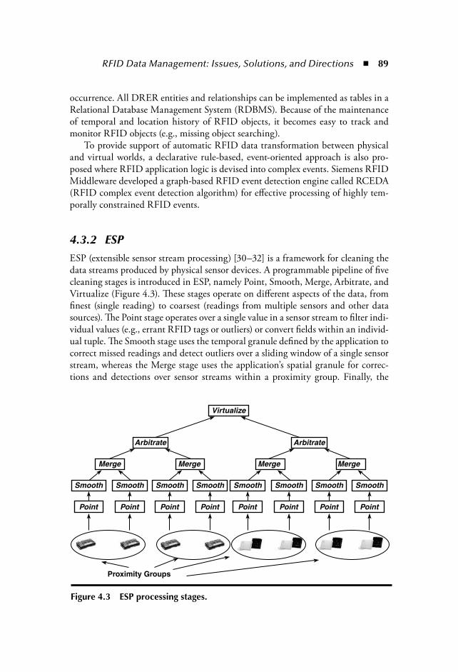
RFID Data Management: Issues, Solutions, and Directions 89
occurrence. All DRER entities and relationships can be implemented as tables in aRelational Database Management System (RDBMS). Because of the maintenanceof temporal and location history of RFID objects, it becomes easy to track andmonitor RFID objects (e.g., missing object searching).
To provide support of automatic RFID data transformation between physicaland virtual worlds, a declarative rule-based, event-oriented approach is also pro-posed where RFID application logic is devised into complex events. Siemens RFIDMiddleware developed a graph-based RFID event detection engine called RCEDA(RFID complex event detection algorithm) for effective processing of highly tem-porally constrained RFID events.
4.3.2 ESPESP (extensible sensor stream processing) [30–32] is a framework for cleaning thedata streams produced by physical sensor devices. A programmable pipeline of fivecleaning stages is introduced in ESP, namely Point, Smooth, Merge, Arbitrate, andVirtualize (Figure 4.3). These stages operate on different aspects of the data, fromfinest (single reading) to coarsest (readings from multiple sensors and other datasources). The Point stage operates over a single value in a sensor stream to filter indi-vidual values (e.g., errant RFID tags or outliers) or convert fields within an individ-ual tuple. The Smooth stage uses the temporal granule defined by the application tocorrect missed readings and detect outliers over a sliding window of a single sensorstream, whereas the Merge stage uses the application’s spatial granule for correc-tions and detections over sensor streams within a proximity group. Finally, the
Virtualize
Arbitrate Arbitrate
Merge
Smooth
Point Point
Proximity Groups
Point Point Point Point Point Point
Smooth Smooth Smooth Smooth Smooth Smooth Smooth
Merge Merge Merge
Figure 4.3 ESP processing stages.
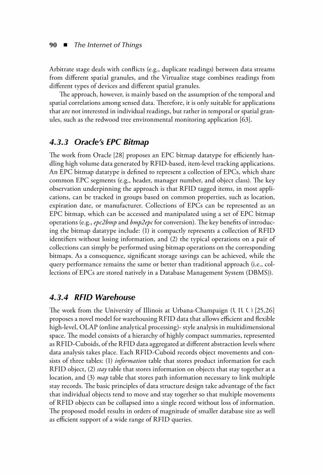
90 The Internet of Things
Arbitrate stage deals with conflicts (e.g., duplicate readings) between data streamsfrom different spatial granules, and the Virtualize stage combines readings fromdifferent types of devices and different spatial granules.
The approach, however, is mainly based on the assumption of the temporal andspatial correlations among sensed data. Therefore, it is only suitable for applicationsthat are not interested in individual readings, but rather in temporal or spatial gran-ules, such as the redwood tree environmental monitoring application [63].
4.3.3 Oracle’s EPC BitmapThe work from Oracle [28] proposes an EPC bitmap datatype for efficiently han-dling high volume data generated by RFID-based, item-level tracking applications.An EPC bitmap datatype is defined to represent a collection of EPCs, which sharecommon EPC segments (e.g., header, manager number, and object class). The keyobservation underpinning the approach is that RFID tagged items, in most appli-cations, can be tracked in groups based on common properties, such as location,expiration date, or manufacturer. Collections of EPCs can be represented as anEPC bitmap, which can be accessed and manipulated using a set of EPC bitmapoperations (e.g., epc2bmp and bmp2epc for conversion). The key benefits of introduc-ing the bitmap datatype include: (1) it compactly represents a collection of RFIDidentifiers without losing information, and (2) the typical operations on a pair ofcollections can simply be performed using bitmap operations on the correspondingbitmaps. As a consequence, significant storage savings can be achieved, while thequery performance remains the same or better than traditional approach (i.e., col-lections of EPCs are stored natively in a Database Management System (DBMS)).
4.3.4 RFID WarehouseThe work from the University of Illinois at Urbana-Champaign (UIUC) [25,26]proposes a novel model for warehousing RFID data that allows efficient and flexiblehigh-level, OLAP (online analytical processing)- style analysis in multidimensionalspace. The model consists of a hierarchy of highly compact summaries, representedas RFID-Cuboids, of the RFID data aggregated at different abstraction levels wheredata analysis takes place. Each RFID-Cuboid records object movements and con-sists of three tables: (1) information table that stores product information for eachRFID object, (2) stay table that stores information on objects that stay together at alocation, and (3) map table that stores path information necessary to link multiplestay records. The basic principles of data structure design take advantage of the factthat individual objects tend to move and stay together so that multiple movementsof RFID objects can be collapsed into a single record without loss of information.The proposed model results in orders of magnitude of smaller database size as wellas efficient support of a wide range of RFID queries.

RFID Data Management: Issues, Solutions, and Directions 91
4.3.5 Evaluations and Open IssuesThe aforementioned research projects are compared using the RFID data process-ing dimensions presented in section 4.2.2. Table 4.1 summarizes the results. Forexample, Siemens RFID Middleware partially addresses the inaccuracy issues ofRFID data by supporting the filtering of duplicated readings. The work from Ora-cle addresses explosion of RFID data using EPC bitmap datatype.
From the table, we can see that most of the projects support the modeling oftemporal and spatial characteristics of RFID data. It is also obvious that handlinglarge volumes of RFID data is a popular trend. However, it is worth mentioningthat inaccuracy, implicit references, and active lifespan are neglected by most proj-ects. Only Siemens RFID Middleware provides very limited support.
Although a number of efforts and results have been made and obtained in thisarea, RFID data processing technology is still far from mature and requires signifi-cant efforts to address some open research challenges:
Accurate and reliable RFID data provisioning: The unreliability of RFIDdata has been widely considered as a principle challenge in RFID applica-tions [9,31]. The accuracy of RFID data is extremely important for RFID-enabled applications in the sense that RFID data is mainly used to automatebusiness processes and applications. The imperfection of RFID informationmay misguide users using RFID applications. For example, a ghost read ata checkout point might trigger a charge to the customer although she is notpurchasing the corresponding goods. We believe that extensive research isneeded for highly reliable provisioning of RFID data.General approach for efficient RFID data management: RFID systems maygenerate large volume of data [9,64]. Accumulation of RFID data can easilylead to poor performance (e.g., slower queries and updates). Therefore, effi-cient management of large amount of RFID data is a critical issue that mustbe dealt with in RFID applications. Current solutions on efficient RFIDdata management focus on data mining-based approaches [26,28] thatassume RFID data shares some common properties (e.g., move together inbulky mode, with the same expired date) and can be grouped based on suchproperties, thereby fitting well to only a limited number of RFID applica-tions (e.g., supply chain management). A more general approach, therefore,is needed for handling massive RFID data. Given the limited active lifes-pan of RFID data, we believe that novel mechanisms (e.g., partitioning ofRFID data) will become increasingly important.Flexible and intelligent RFID data transformation and aggregation: RawRFID data presents little value without transforming into more meaning-ful form that is suitable for application-level interactions. Moreover, RFIDdata carries implicit meanings and associated relationships (e.g., contain-ment) with other RFID data, where appropriate inferences have to be
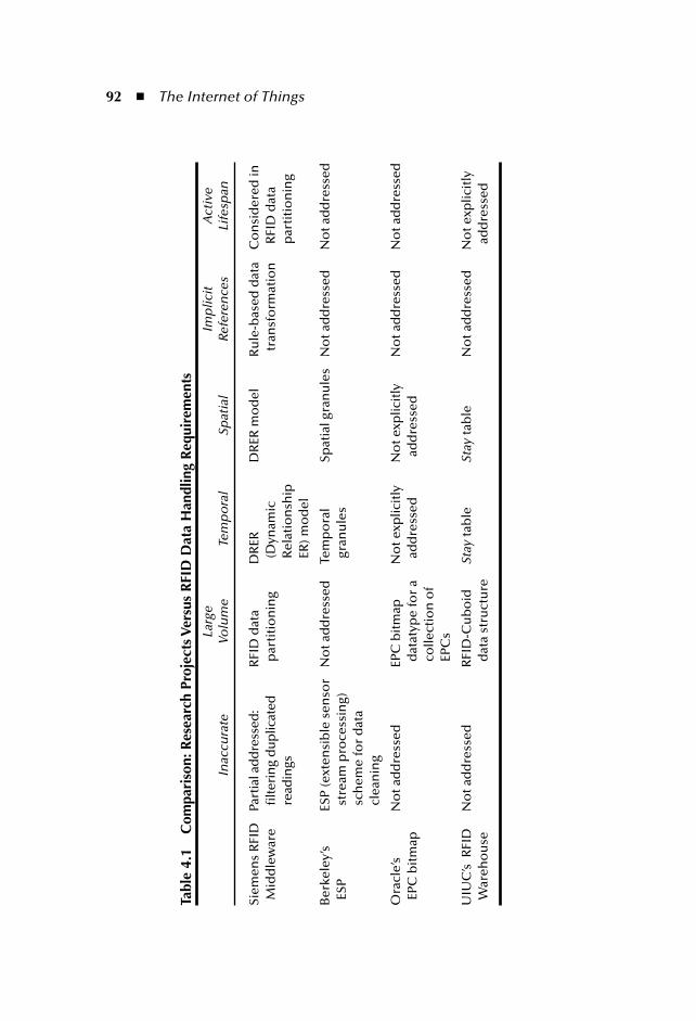
92 The Internet of Things
Tabl
e 4.
1C
ompa
riso
n: R
esea
rch
Proj
ects
Ver
sus
RFI
D D
ata
Han
dlin
g R
equi
rem
ents
Inac
cura
teLa
rge
Volu
me
Tem
po
ral
Spat
ial
Imp
licit
Refe
ren
ces
Act
ive
Life
span
Siem
ens
RFI
D
Mid
dle
war
ePa
rtia
l add
ress
ed:
filte
rin
g d
up
licat
ed
read
ings
RFI
D d
ata
par
titi
on
ing
DR
ER(D
ynam
icR
elat
ion
ship
ER) m
od
el
DR
ER m
od
elR
ule
-bas
ed d
ata
tran
sfo
rmat
ion
Co
nsi
der
ed in
R
FID
dat
a p
arti
tio
nin
g
Ber
kele
y’s
ESP
ESP
(ext
ensi
ble
sen
sor
stre
am p
roce
ssin
g)
sch
eme
for
dat
a cl
ean
ing
No
t ad
dre
ssed
Tem
po
ral
gran
ule
sSp
atia
l gra
nu
les
No
t ad
dre
ssed
No
t ad
dre
ssed
Ora
cle’
s EP
C b
itm
apN
ot a
dd
ress
edEP
C b
itm
ap
dat
atyp
e fo
r a
colle
ctio
n o
f EP
Cs
No
t exp
licit
ly
add
ress
edN
ot e
xplic
itly
ad
dre
ssed
No
t ad
dre
ssed
N
ot a
dd
ress
ed
UIU
C’s
RFI
D
War
eho
use
No
t ad
dre
ssed
RFI
D-C
ub
oid
d
ata
stru
ctu
reSt
ayta
ble
Stay
tab
leN
ot a
dd
ress
edN
ot e
xplic
itly
ad
dre
ssed
RFID Data Management: Issues, Solutions, and Directions 93
made [9]. For example, in Figure 4.4, two observations of the items anda case happening in a certain time interval may imply that the items arepacked into the case. This normally requires the formation of relationshipsamong RFID objects and the devising of business logics of RFID appli-cations, which has been identified as a difficult issue for RFID applica-tions [44]. The extension of event modeling techniques is a natural step inthis direction. Indeed, a few research efforts for event-driven RFID datamanagement are emerging [22,66].
4.4 RFID Integration PlatformsMajor software vendors like Sun Microsystems, SAP, BEA Systems, and IBM, andresearch organizations, such as WINMEC at UCLA, Auto-ID labs, and SiemensResearch are currently working on implementing RFID integration platforms.Due to the large number of products, both existing and emerging, we will notcover all of them in this chapter. Instead, we focus on the major players in thisarena and overview the main features of a set of representative platforms. It shouldbe noted that for commercial products, our judgment is based on user manualsand white papers because there are few or no technical publications detailing theseproducts.
4.4.1 UCLA WinRFIDWinRFID [47] is a multilayered middleware system developed using Microsoft.NET [39] framework, that enables rapid RFID application development. It consists
Reader A
Item e1: Items observed
t_begin(e1) t_begin(e2)t_end(e1) t_end(e2)
distance(e1, e2)
time
e3:Items packed into casee2: Case
observed
Reader B
Figure 4.4 Complex events for RFID data aggregation.

94 The Internet of Things
of five main layers: physical, protocol, data processing, XML framework, and datapresentation. The physical layer deals with the hardware, including readers, tags,and other sensors. The protocol layer abstracts the reader-tag protocols. The dataprocessing layer processes the data streams generated by the RFID reader network.Finally, XML framework and data presentation layers deal with data representationand presentation, respectively. Middleware modules are deployed as independentcomponents that run in dispersed machines. Currently, a Web service-based dis-tributed architecture is under development.
To support the extendibility of its platform, WinRFID exploits the runtimeplug-in feature of .NET. New readers, new protocols, and new data transformationrules can be added to corresponding modules with minimum disruption of theexisting infrastructure. Data filtering, aggregation, and adaptation are handled bya rule-based engine that is tightly coupled in the architecture of WinRFID.
4.4.2 Siemens RFID MiddlewareThe Siemens RFID Middleware [65,66] is a RFID data management system,which provides an integrated solution for RFID applications. It offers the followingfunctionalities: automatic data acquisition, filtering, and transformation; expressivedata modeling and effective query support; and adaptation to different applicationswith minimum configurations.
The Siemens RFID Middleware consists of three main components: RFID read-ers, Event managers, and RFID data server. Event managers dynamically receive datafrom readers, preliminarily filter the data, and forward the data (formatted in PML)to the RFID data server. The RFID data server includes: (1) RFID data manager,for RFID data processing (i.e., semantic data filtering and data aggregation), RFIDobject tracking and monitoring, and decision-making support; (2) RFID data store forRFID data maintenance (i.e., storing, partitioning, and retrieval of RFID data); and(3) application integration interface for integrating system with other applications.
4.4.3 SAP Auto-ID InfrastructureSAP Auto-ID Infrastructure (SAP AII) [6,53] is a middleware that adds a layer ofintelligence between automated communication and sensing devices (e.g., RFIDreaders, Bluetooth devices, and barcode devices) and enterprise applications. SAPAII is built on SAP’s Web Application Server, which is part of the company’sNetWeaver [54] integration and application platform. It converts RFID and sensordata into business process information by associating the data with specified map-ping rules (e.g., forwarding observation data directly to backend systems, executingpredefined business logic) and metadata.
The architecture of SAP AII consists of four system layers: device layer, deviceoperation layer, business process bridging layer, and enterprise application layer. The

RFID Data Management: Issues, Solutions, and Directions 95
device layer supports different types of sensor devices via a hardware-independent,low-level interface. The device operation layer contains one or more device control-lers, coordinating multiple devices. The business process bridging layer associatesobservation messages with existing business processes, realized by a componentcalled Auto-ID node. There can be multiple Auto-ID nodes in SAP AII. Finally,the enterprise application layer supports business processes of enterprise applica-tions, such as supply chain management, customer relationship management, run-ning on either SAP or non-SAP backend systems.
To allow the testing of an Auto-ID deployment without the installation ofphysical devices, SAP AII also provides tools for simulating RFID readers andmessages. To support the flexibility of the infrastructure, SAP AII exploits a cus-tomizable rule-based approach in specifying and executing business logic at theAuto-ID nodes.
4.4.4 Sun Java System RFID SoftwareJava System RFID Software [61] is one of the first RFID integration platformsfocusing on large-scale deployments. It is designed on a service-oriented architec-ture, providing network services to applications through a number of standard pro-tocols and interfaces. The bottom of the RFID software architecture are tag readersor sensors that are responsible for reading tagged items. The data is sent to Java Sys-tem RFID Software for processing. The topmost layer of the architecture is enter-prise information systems to be integrated, such as enterprise resource planning.
Java System RFID Software consists of two major components: the Java SystemRFID event manager and the Java System RFID information server. The Java Sys-tem RFID event manager is designed to process (filter and aggregate) RFID data.It implements a federated service architecture, which essentially provides distrib-uted, self-organizing, and network-centric capabilities. This architecture makes theRFID event manager not only scalable, but also adaptable to unforeseen changeson the network. The Java System RFID information server provides access to thebusiness events generated by the RFID event manager as well as serves as an inte-gration layer that offers options for integrating with enterprise applications.
The Java System RFID Software architecture is built with Java Enterprise Sys-tem [60], which delivers a set of shared technology components and services forenhanced integration and simplified maintenance. Network identity and securityservices from the Java Enterprise System, for instance, help secure the Java SystemRFID Software.
4.4.5 EPCglobal NetworkThe EPCglobal Network is an architecture that is often referred to in literatureas the “Internet of things” [56]. It has been designed by the Auto-ID Center and

96 The Internet of Things
developed further by the EPCglobal. The basic idea behind the framework is torealize a so-called data-on-network system, where RFID tags contain an unam-biguous ID, namely Electronic Product Code (EPC), and other data pertaining tothe objects is stored and accessed over the Internet.
The major components of the EPCglobal Network include the Object Nam-ing Service (ONS) and the EPC Information Service (EPCIS). The ONS providesreference to the saved object information through EPC, thus helping the discov-ery of RFID objects over the network. EPCIS offers an interface for accessingthe stored RFID data. To exchange RFID data between EPCglobal network andexternal applications, an XML-based markup language, PML, is proposed. Theadvantages of EPCglobal network include the possibility of using low-cost RFIDtags and a more scalable architecture. It is worth mentioning that in order to trackRFID objects in the EPCglobal network, the movement of these objects has to becontinuously published to a centralized discovery service, which unfortunately,prevents the network from realizing a full-fledged distributed architecture [1].
4.4.6 Other PlatformsBEA WegLogic RFID. BEA WebLogic RFID products [5] consists of BEA Web-Logic RFID Edge Server, BEA WebLogic RFID Enterprise Server, and BEA Web-Logic RFID Compliance Express. RFID Edge Server is a lightweight softwarethat can be deployed at various sites. It provides a comprehensive software infra-structure for filtering, integrating, disseminating RFID data, and monitoring andconfiguring RFID readers. RFID Enterprise Server provides the standards-basedinfrastructure for centrally managing RFID data collected from RFID Edge Serv-ers. Finally, RFID Compliance Express is designed to meet current compliancechallenges while establishing a foundation for future expansion.
IBM WebSphere RFID. The IBM RFID solution [29] is made up of threecomponents: devices, WebSphere RFID Premises Server, and a WebSphereintegration server. RFID devices (e.g., readers, scanners, printers) have to beembedded with the WebSphere RFID Device Infrastructure, which is a soft-ware that supports functions for RFID data collection and delivery. WebSphereRFID Premises Server is a middleware that aggregates, monitors, interprets,and escalates RFID data, and provides interface for the integration (via an inte-gration server, such as WebSphere Business Integration Server) with enterpriseapplications.
Sybase RFID Solutions. The core part of the Sybase RFID solutions [62] is a lay-ered RFID architecture, which consists of six major components: the physical devicelayer, the RFID network layer, the process layer, the persistence layer, the integra-tion layer, and the presentation layer. The RFID network layer is implementedthrough Sybase RFID Anywhere, a middleware platform that supports the

RFID Data Management: Issues, Solutions, and Directions 97
reading, writing, filtering, grouping, and routing of RFID data generated by readersand related peripherals. The architecture also provides tools for data analysis andmobilization (e.g., delivering RFID data to mobile devices).
4.4.7 Evaluations and Open IssuesIn Table 4.2, major RFID integration platforms are compared using the RFID dataintegration dimensions (section 4.2.3). For example, scalability of WinRFID is sup-ported by deploying RFID middleware components as self-contained, distributedmodules. Heterogeneity is partially addressed through the abstraction of publishedprotocols and the usage of XML framework for data representation. Openness isprovided by exploiting a standard-based framework, such as EPC, Web services,and XML. Flexibility is supported by a rule-based engine and a plug-ins frame-work based on .Net platform. Manageability is provided by WinRFID manage-ment console. Finally, security is partially addressed through authentication andaccess restriction support of RFID data.
From the table, one can see that most RFID integration platforms pay par-ticular attentions to the issues like scalability, heterogeneity, and openness in theirdesign. However, they either totally neglect or provide very limited support to theissues like flexibility, security, and privacy. Although the current solutions providethe foundation for building RFID applications, several research issues still need tobe addressed. In particular, we identify the following directions for future research,namely support of large scale applications, seamless integration of legacy systemsand environmental sensors, security, and privacy.
Support of large scale applications: In spite of many small RFID pilot appli-cations (e.g., warehouse monitoring), there present significant challengesfor developing and deploying large-scale and distributed applications (e.g.,supply chain management across companies). First, the nature of RFIDapplications as well as scalability requirements call for a completely distrib-uted system architecture. Although some of the current existing platformssupport the distribution of some functionalities (e.g., RFID edge process-ing), a full-fledged distributed architecture is needed where functionalitiescan be distributed and replicated, and data can be shared and synchronizedacross multiple nodes. Second, the deployment of a large distributed systemrequires the ability to continuously monitor the state of the system andadaptively adjust its behavior. Given the large number and highly distrib-uted nature of RFID devices, the administration tools for visualizing, con-figuring, testing, and monitoring RFID devices and system componentswill become increasingly important.
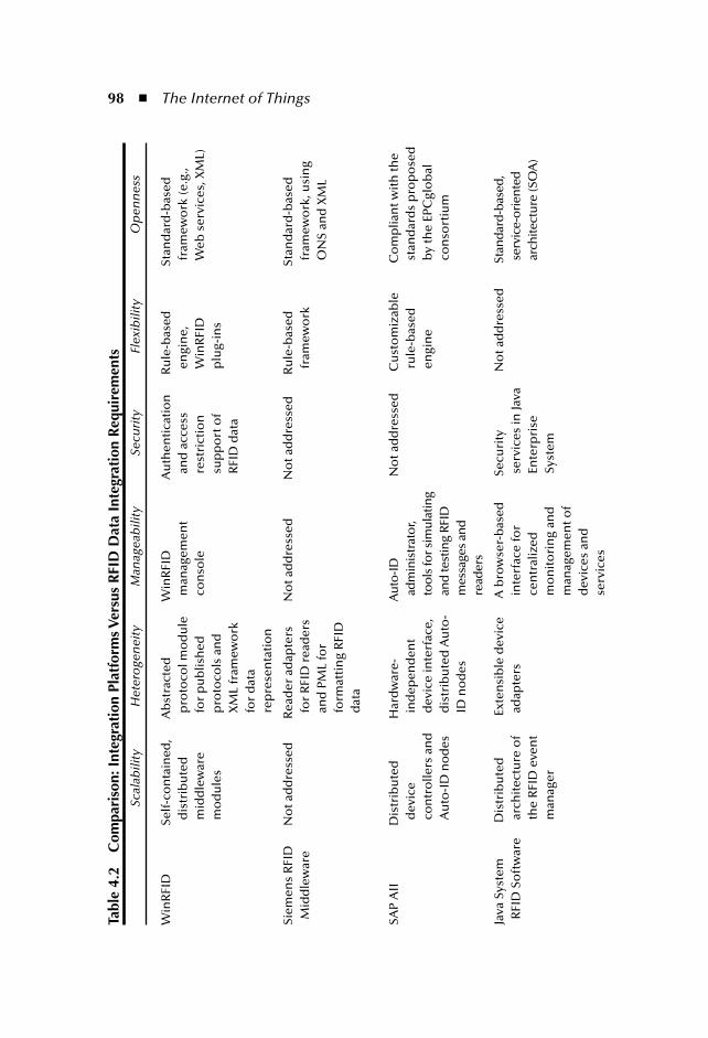
98 The Internet of ThingsTa
ble
4.2
Com
pari
son:
Int
egra
tion
Pla
tfor
ms V
ersu
s R
FID
Dat
a In
tegr
atio
n R
equi
rem
ents
Scal
abili
tyH
eter
oge
nei
tyM
anag
eab
ility
Secu
rity
Flex
ibili
tyO
pen
nes
s
Win
RFI
DSe
lf-c
on
tain
ed,
dis
trib
ute
dm
idd
lew
are
mo
du
les
Ab
stra
cted
pro
toco
l mo
du
le
for
pu
blis
hed
p
roto
cols
an
d
XM
L fr
amew
ork
fo
r d
ata
rep
rese
nta
tio
n
Win
RFI
Dm
anag
emen
t co
nso
le
Au
then
tica
tio
n
and
acc
ess
rest
rict
ion
sup
po
rt o
f R
FID
dat
a
Ru
le-b
ased
engi
ne,
Win
RFI
Dp
lug-
ins
Stan
dar
d-b
ased
fram
ewo
rk (e
.g.,
Web
ser
vice
s, X
ML)
Siem
ens
RFI
D
Mid
dle
war
eN
ot a
dd
ress
edR
ead
er a
dap
ters
fo
r R
FID
rea
der
s an
d P
ML
for
form
atti
ng
RFI
D
dat
a
No
t ad
dre
ssed
No
t ad
dre
ssed
Ru
le-b
ased
fr
amew
ork
Stan
dar
d-b
ased
fram
ewo
rk, u
sin
g O
NS
and
XM
L
SAP
AII
Dis
trib
ute
d
dev
ice
con
tro
llers
an
d
Au
to-I
D n
od
es
Har
dw
are-
ind
epen
den
td
evic
e in
terf
ace,
d
istr
ibu
ted
Au
to-
ID n
od
es
Aut
o-ID
ad
min
istr
ator
, to
ols
for s
imul
atin
g an
d te
stin
g RF
ID
mes
sage
s an
d
read
ers
No
t ad
dre
ssed
C
ust
om
izab
le
rule
-bas
eden
gin
e
Co
mp
lian
t wit
h th
e st
and
ard
s p
rop
ose
d
by
the
EPC
glo
bal
co
nso
rtiu
m
Java
Sys
tem
R
FID
So
ftw
are
Dis
trib
ute
d
arch
itec
ture
of
the
RFI
D e
ven
t m
anag
er
Ext
ensi
ble
dev
ice
adap
ters
A b
row
ser-
bas
ed
inte
rfac
e fo
r ce
ntr
aliz
ed
mo
nit
ori
ng
and
m
anag
emen
t of
dev
ices
an
d
serv
ices
Sec
uri
ty
serv
ices
in Ja
va
Ente
rpri
seSy
stem
No
t ad
dre
ssed
S
tan
dar
d-b
ased
, se
rvic
e-o
rien
ted
ar
chite
ctu
re (S
OA
)
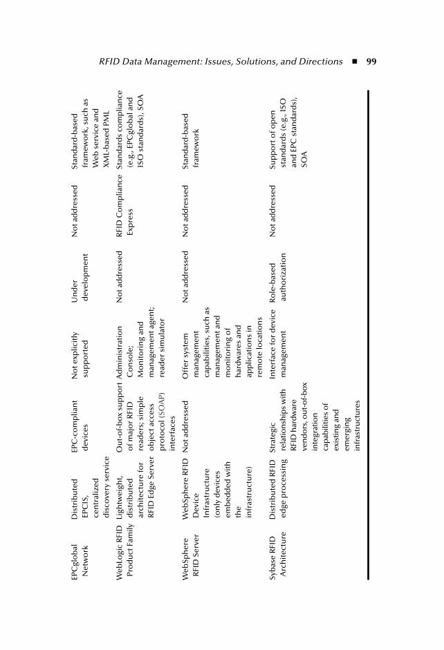
RFID Data Management: Issues, Solutions, and Directions 99EP
Cgl
ob
alN
etw
ork
D
istr
ibu
ted
EP
CIS
,ce
ntr
aliz
ed
dis
cove
ry s
ervi
ce E
PC-c
om
plia
nt
dev
ices
No
t exp
licit
ly
sup
po
rted
U
nd
er
dev
elo
pm
ent
No
t ad
dre
ssed
S
tan
dar
d-b
ased
fr
amew
ork
, su
ch a
s W
eb s
ervi
ce a
nd
X
ML-
bas
ed P
ML
Web
Logi
c R
FID
Pr
od
uct
Fam
ily L
igh
twei
ght,
dis
trib
ute
dar
chit
ectu
re fo
r R
FID
Ed
ge S
erve
r
Ou
t-o
f-b
ox
sup
po
rt
of m
ajo
r R
FID
re
ader
s; s
imp
le
ob
ject
acc
ess
pro
toco
l (SO
AP)
inte
rfac
es
Ad
min
istr
atio
n
Co
nso
le;
Mo
nit
ori
ng
and
m
anag
emen
t age
nt;
read
er s
imu
lato
r
No
t ad
dre
ssed
R
FID
Co
mp
lian
ce
Exp
ress
Sta
nd
ard
s co
mp
lian
ce
(e.g
., EP
Cgl
ob
al a
nd
IS
O s
tan
dar
ds)
, SO
A
Web
Sph
ere
RFI
D S
erve
r W
ebSp
her
e R
FID
D
evic
eIn
fras
tru
ctu
re(o
nly
dev
ices
em
bed
ded
wit
h
the
infr
astr
uct
ure
)
No
t ad
dre
ssed
O
ffer
sys
tem
m
anag
emen
t ca
pab
iliti
es, s
uch
as
man
agem
ent a
nd
m
on
ito
rin
g o
f h
ard
war
es a
nd
ap
plic
atio
ns
in
rem
ote
loca
tio
ns
No
t ad
dre
ssed
N
ot a
dd
ress
ed
Sta
nd
ard
-bas
ed
fram
ewo
rk
Syb
ase
RFI
D
Arc
hit
ectu
re D
istr
ibu
ted
RFI
D
edge
pro
cess
ing
Str
ateg
ic
rela
tion
ship
s w
ith
RFI
D h
ard
war
e ve
nd
ors
, ou
t-o
f-b
ox
inte
grat
ion
ca
pab
ilitie
s o
f ex
istin
g an
d
emer
gin
g in
fras
tru
ctu
res
Inte
rfac
e fo
r d
evic
e m
anag
emen
t R
ole
-bas
ed
auth
ori
zati
on
No
t ad
dre
ssed
S
up
po
rt o
f op
en
stan
dar
ds
(e.g
., IS
O
and
EPC
sta
nd
ard
s),
SOA
100 The Internet of Things
Seamless integration of legacy systems and environmental sensors: Support ofintegration of existing systems is of paramount importance for RFID inte-gration platforms. These legacy software systems are normally matured,heavily used, and constitute massive corporate assets [57]. It is costly, orimpossible, to scrap the legacy systems and replace them with new ones.Many businesses seek ways to maximize their existing investment andpreserve valuable business knowledge while adapting to rapidly evolvingtechnologies. Currently, vendors and researchers are developing RFIDmiddlewares (e.g., SAP AII [53], Sybase RFID [62], and WinRFID [47])that will link new RFID systems into existing infrastructures. We expectmore research effort in this direction. Moreover, many researchers believethat integration of sensors and RFID tags will make it ideal for obtaininginformation about the physical world [40,7]. An RFID tag could returnenvironmental data along with an object’s identity. For example, a sensor-enabled RFID tag attached to an airplane part could record the stress andshock experienced during a flight, which could be used by a maintenanceofficer to make the preventive maintenance schedule for this particularpart. Unfortunately, RFID readers are discrete event sources, whereas envi-ronmental sensors provide a stream of periodic events. This mismatch hasto be represented and resolved in order to seamlessly integrate RFID andenvironmental sensors [6,58].Security: RFID systems are increasingly being used in high security appli-cations, such as access control [27], electronic passports [72,4], and sys-tems for making payments [17,8,18] or issuing tickets [38]. Security is acritical issue for RFID technologies to be adopted and must be enforcedto give businesses the confidence that their data is safely handled. A fewsolutions have proposed authenticating and encrypting mechanismsbetween RFID tags and readers [34,51]. However, data encryption andauthentication increase the resource consumption and the latency of readcycles [23,46]. Intensive work is needed for developing comprehensivesolutions that not only protect RFID information, but maintain desirablesystem performance.Privacy: Privacy is another fundamental concern with RFID systems. Itis generally (mis)perceived as an issue whose natural solution consists ofgood security mechanisms. Although security and privacy are two tightlyinterrelated issues, securing RFID applications does not necessarily ensureprivacy. There are two notable privacy issues: (1) leaking information per-taining to personal property, and (2) tracking the consumer’s spending his-tory and patterns and physical whereabouts [43,24]. Examples of RFIDprivacy threads include terrorists scanning digital passports to target specificnationalities, and police abusing a convenient new means of cradle-to-gravesurveillance. To address privacy threads of RFID users, not only techni-cal solutions (e.g., Blocker Tag [35], Hash-Lock Scheme [70], Internal
RFID Data Management: Issues, Solutions, and Directions 101
re-encryption scheme [36]), but also social and legal countermeasures (e.g.,RFID policies [11,52], RFID bills [42,41]) need to be implemented toensure consumers that their data will not be misappropriated [43,23].
4.5 ConclusionThe ability of RFID technology to precisely identify objects at low cost and withoutline of sight creates many new and exciting application areas. In the future, thiswide range of applications will make RFID an integral part of our daily lives. How-ever, despite the obvious potential, there are a number of fundamental researchand development issues that persist. Development of RFID applications needs notonly to deal with the unique characteristics of RFID data, but to consider specificdata integration requirements of system architectures. As we have indicated, onlywhen robust, scalable, secure solutions have been found will the promise of RFIDapplications be fully realized.
In recent years, the field of RFID is becoming a vibrant and rapidly expand-ing area of research and development. Many researchers and vendors are currentlyengaged in proposing data management solutions needed for the development ofRFID applications. Along with the current research efforts, we encourage moreinsight into the problems of this nascent technology, and more development insolutions to the open research issues as described in this chapter.
Reference [1] R. Agrawal, A. Cheung, K. Kailing, and S. Schonauer. Towards Traceability
Across Sovereign, Distributed RFID Databases. In Proc. of the 10th International Database Engineering and Applications Symposium (IDEAS’06), Delhi, India,December 2006.
[2] R. Angeles. RFID technologies: Supply-chain applications and implementationissues. Information Systems Management, 22(1):51–65, 2005.
[3] Z. Asif and M. Mandviwalla. Integrating the supply chain with RFID: A technical andbusiness analysis. Communications of the Association for Information Systems, 15, March2005.
[4] Australian Government Department of Foreign Affairs and Trade. The AustralianePassport. http://www.dfat.gov.au/dept/passports/, visited on 20/05/2006.
[5] BEA Systems. “BEA WebLogic RFID Product Family.” http://www.bea.com/framework.jsp?CNT=index.htm&FP=/content/products/weblogic/rfid/, visited on07/06/2006.
[6] C. Bornhövd, T. Lin, S. Haller, and J. Schaper. Integrating Automatic Data Acqui-sition with Business Processes Experiences with SAP’s Auto-ID Infrastructure. InProc. of the 30th International Conference on Very Large Data Bases (VLDB’04),Toronto, Canada, September 2004.
[7] G. Borriello. RFID: Tagging the world. Communications of the ACM, 48(9):34–37,September 2005.
[8] J. Boyd. Here comes the wallet phone. IEEE Spectrum, 42(11):12–14, 2005.

102 The Internet of Things
[9] S.S. Chawathe, V. Krishnamurthy, S. Ramachandran, and S. Sarma. ManagingRFID Data. In Proc. of the 30th International Conference on Very Large Data Bases (VLDB’04), Toronto, Canada, September 2004.
[10] P.H. Cole. “Fundamentals in Radio Frequency Identification.” http://autoidlabs.eleceng.adelaide.edu.au/Tutorial/SeattlePaper.doc, visited on 22/05/2006.
[11] J. Collins. “European Commission Works on RFID Policy.” http://www.rfid-journal.com/article/articleview/2197/1/1/, March 2006.
[12] J. Curtin, R.J. Kauffman, and F.J. Riggins. Making the most out of RFID technol-ogy: A research agenda for the study of the adoption, usage and impact of RFID.Information Technology and Management Journal, 7(3-4):251–270, 2006.
[13] R. Das and P. Harrop. “RFID Forecasts, Players & Opportunities 2006–2016.”http://www.idtechex.com/products/en/view.asp?productcategoryid=93, visited on03/08/2006.
[14] D.W. Engels. On Ghost Reads in RFID Systems. Technical report, Auto-ID Cen-ter, January 2005.
[15] D.W. Engles and S.E. Sarma. The Reader Collision Problem. In Proc. of the IEEE International Conference on Systems, Man and Cybernetics (SMC’02), Hammamet,Tunisia, October 2002.
[16] EPCglobal. “EPC Tag Data Standards Version 1.1.” http://www.epcglobalinc.org/standards_technology/EPCTagDataSpecification11rev124.pdf, April 2004.
[17] ExxonMobile. “Speedpass System.” https://www.speedpass.com/, visited on 11/05/2006. [18] Fastrak. “Fastrak-Keeping the Bay Area Moving.” http://www.bayareafastrak.org/,
visited on 22/05/2006. [19] K. Finkenzeller. RFID Handbook: Fundamentals and Applications in Contactless
Smart Cards and Identification. John Wiley & Sons, New York, 2003. [20] C. Floerkemeier, D. Anarkat, T. Osinski, and M. Harrison. PML Core Specifica-
tion 1.0. Technical report, Auto-ID Center, September 2003. [21] C. Floerkemeier and M. Lampe. Issues with RFID Usage in Ubiquitous Comput-
ing Applications. In Proc. of the 2nd International Conference on Pervasive Comput-ing (Pervasive’04), Linz/Vienna, Austria, April 2004.
[22] M.J. Franklin, S.R. Jeffery, S. Krishnamurthy, F. Reiss, S. Rizvi, E. Wu, O. Coo-per, A. Edakkunni, and W. Hong. Design Considerations for High Fan-in Sys-tems: The HiFi Approach. In Proc. of the Second Biennial Conference on Innovative Data Systems Research (CIDR’05), Asilomar, CA, January 2005.
[23] S. Garfinkel and B. Rosenberg. RFID: Applications, Security, and Privacy. Addison-Wesley Professional, Reading, MA, 2005.
[24] S.L. Garfinkel, A. Juels, and R. Pappu. RFID privacy: An overview of problemsand proposed solutions. IEEE Security & Privacy, 3(3):34–43, May/June 2005.
[25] H. Gonzalez, J. Han, and X. Li. FlowCube: Constructing RFID FlowCubes forMulti-dimensional Analysis of Commodity Flows. In Proc. of the 32nd International Conference on Very Large Data Bases (VLDB’06), Seoul, Korea, September 2006.
[26] H. Gonzalez, J. Han, X. Li, and D. Klabjan. Warehousing and Analyzing MassiveRFID Data Sets. In Proc. of the 22nd International Conference on Data Engineering (ICDE’06), Atlanta, GA, April 2006, visited on 11/08/2006.
[27] HID Web Site. http://www.hidcorp.com/technologies.php, visited on 11/08/2006.

RFID Data Management: Issues, Solutions, and Directions 103
[28] Y. Hu, S. Sundara, T. Chorma, and J. Srinivasan. Supporting RFID-Based ItemTracking Applications in Oracle DBMS Using a Bitmap Datatype. In Proc. of the 31st International Conference on Very Large Data Bases (VLDB’05), Trondheim,Norway, September 2005.
[29] IBM. “WebSphere RFID Premises Server.” http://www-306.ibm.com/software/pervasive/ws_rfid_ premises_server/, visited on 01/07/2006.
[30] S. Jeffery, M. Garofalakis, and M. Franklin. Adaptive Cleaning for RFID DataStreams. In Proc. of the 32nd International Conference on Very Large Data Bases (VLDB’06), Seoul, Korea, September 2006.
[31] S.R. Jeffery, G. Alonso, M.J. Franklin, W. Hong, and J. Widom. A PipelinedFramework for Online Cleaning of Sensor Data Streams. In Proc. of the 22nd Inter-national Conference on Data Engineering (ICDE’06), Atlanta, GA, April 2006.
[32] S.R. Jeffery, G. Alonso, M.J. Franklin, W. Hong, and J. Widom. Declarative Sup-port for Sensor Data Cleaning. In Proc. of the 4th International Conference on Per-vasive Computing (Pervasive’06), Dublin, Ireland, May 2006.
[33] J.R. Johnson. “Wal-Mart: RFID Reduces Out-Of-Stocks by Up to 62 Percent.”http://www.dcvelocity.com/articles/rfidww/rfidww20060517/walmart_rfid.cfm,visited on 14/07/2006.
[34] A. Juels. RFID security and privacy: A research survey. IEEE Journal on Selected Areas in Communication, 24(2), 2006.
[35] A. Juels, R.L. Rivest, and M. Szydlo. The Blocker Tag: Selective Blocking of RFIDTags for Consumer Privacy. In Proc. of the 10th ACM Conference on Computer and Communications Security (CCS’03), Washington, D.C., October 2003.
[36] S. Kinoshita, M. Ohkubo, F. Hoshino, G. Morohashi, O. Shionoiri, and A. Ka-nai. Privacy Enhanced Active RFID Tag. In Proc. of 1st International Workshop on Exploiting Context Histories in Smart Environments (ECHISE’05), Munich, Ger-many, 2005.
[37] J. Landt. The history of RFID. IEEE Potentials, 24(4):8–11, October/November 2005. [38] J. Libbenga. “World Cup Tickets Will Contain RFID Chips.” http://www.thereg-
ister.co.uk/2005/04/04/world_cup_rfid/ visited on 20/05/2006. [39] Microsoft. “.NET.” http://www.microsoft.com/net/default.mspx, 2006. [40] B. Nath, F. Reynolds, and R. Want. RFID technology and applications. IEEE Per-
vasive Computing, 7(1):22–24, January/March 2006. [41] M.C. O’Connor. “California Senate Approves RFID Bill.” http://www.rfidjournal.
com/article/articleview/1602/1/130/, May 2005. [42] M.C. O’Connor. “U.S. Bill Includes RFID Provision for Pets.” http://www.rfid-
journal.com/article/articleview/1976/1/1/, November 2005. [43] M. Ohkubo, K. Suzuki, and S. Kinoshita. RFID privacy issues and technical chal-
lenges. Communications of the ACM, 48(9):66–71, September 2005. [44] T. Palamides. “RFID 2004 Forum Report.” http://www.wireless.ucla.edu/techre-
ports2/RFID-2004-Forum.pdf, visited on 12/04/2006. [45] M. Palmer. “Build an Effective RFID Architecture.” http://www.rfidjournal.com/
article/articleview/781/1/82/, visited on 16/06/2006. [46] T. Phillips, T. Karygiannis, and R. Kuhn. Security standards for the RFID mar-
ket. IEEE Security & Privacy, 3(5):85–89, November/December 2005.

104 The Internet of Things
[47] B.S. Prabhu, X. Su, H. Ramamurthy, C.-C. Chu, and R. Gadh. WinRFID—Amiddleware for the enablement of radio frequency identification (RFID)-basedapplications. In Mobile, Wireless and Sensor Networks: Technology, Applications and Future Directions, 313–336. Wiley–IEEE Press, New York, March 2006.
[48] S. Pradhan, G. Lyon, I. Robertson, L. Erickson, L. Repellin, C. Brignone, M. Mes-arina, B. Serra, V. Deolalikar, T. Connors, M. Jam, J. Recker, C. Gouguenheim,I. Robinson, C. Sayers, and G. Gualdi. RFID and Sensing in the Supply Chain:Challenges and Opportunities. Technical Report HPL-2005-16, HP Labs, PaloAlto, CA, February 2005.
[49] J. Rao, S. Doraiswamy, H. Thakkar, and L. Colby. A Deferred Cleansing Approachfor RFID Data Analytics. In Proc. of the 32nd International Conference on Very Large Data Bases (VLDB’06), Seoul, Korea, September 2006.
[50] M.R. Rieback, B. Crispo, and A.S. Tanenbaum. Is Your Cat Infected with a Com-puter Virus? In Proc. of 4th IEEE International Conference on Pervasive Computing and Communications (PerCom’06), Pisa, Italy, March 2006a.
[51] M.R. Rieback, B. Crispo, and A.S. Tanenbaum. The evolution of RFID security.IEEE Pervasive Computing, 7(1):62–69, January/March 2006b.
[52] M. Roberti. “DOD Releases Final RFID Policy.” http://www.rfidjournal.com/arti-cle/articleview/1080/1/14/, August 2004.
[53] SAP. “SAP Auto-ID Infrastructure.” http://www.sap.com/solutions/netweaver/autoidinfrastructure.epx, visited on 04/07/2006.
[54] SAP. “SAP NetWeaver.” http://www.sap.com/solutions/netweaver/index.epx. [55] S. Sarma. Integrating RFID. ACM Queue, 2(7):50–57, October 2004. [56] E.W. Schuster, S.J. Allen, and D.L. Brock. Global RFID: The Value of the EPCglobal
Network for Supply Chain Management. Springer, Heidelberg, Germany, 2007. [57] R.C. Seacord, D. Plakosh, and G.A. Lewis. Modernizing Legacy Systems: Software
Technologies, Engineering Processes, and Business Practices. Addison-Wesley, Reading,MA, 2003.
[58] J.R. Smith, K.P. Fishkin, B. Jiang, A. Mamishev, M. Philipose, A.D. Rea, S. Roy,and K. Sundara-Rajan. RFID-based techniques for human-activity detection.Communications of the ACM, 48(9):39–44, 2005.
[59] V. Stanford. Pervasive computing goes the last hundred feet with RFID systems.IEEE Pervasive Computing, 2(2):9–14, April/May 2003.
[60] Sun Microsystems. “Sun Java Enterprise System.” http://www.sun.com/software/javaenterprisesystem/, visited on 10/09/2006.
[61] Sun Microsystems. “Sun Java System RFID Software.” http://www.sun.com/software/ products/rfid/, visited on 10/09/2006.
[62] Sybase. “Sybase RFID Solutions.” http://www.sybase.com/rfid, visited on 10/09/2006. [63] G. Tolle, J. Polastre, R. Szewczyk, D. Culler, N. Turner, K. Tu, S. Burgess,
T. Dawson, P. Buonadonna, D. Gay, and W. Hong. A Macroscope in the Red-woods. In Proc. of the 3rd ACM Conference on Embedded Networked Sensor Systems (SenSys’05), San Diego, CA, November 2005.
[64] Venture Development Corporation (VDC). http://www.vdc-corp.com/, visited on05/06/2006.
RFID Data Management: Issues, Solutions, and Directions 105
[65] F. Wang and P. Liu. Temporal Management of RFID Data. In Proc. of the 31st International Conference on Very Large Data Bases (VLDB’05), Trondheim, Norway,September 2005.
[66] F. Wang, S. Liu, P. Liu, and Y. Bai. Bridging Physical and Virtual Worlds: CompexEvent Processing for RFID Data Streams. In Proc. of the 10th International Confer-ence on Extending Database Technology (EDBT’2006), Munich, Germany, March2006.
[67] R. Want. An introduction to RFID technology. IEEE Pervasive Computing,7(1):25–33, January/March 2006.
[68] R. Want, K.P. Fishkin, A. Gujar, and B.L. Harrison. Bridging Physical and VirtualWorlds with Electronic Tags. In Proc. of the SIGCHI Conference on Human Factors in Computing Systems (CHI’99), Pittsburgh, PA, May 1999.
[69] R. Weinstein. RFID: A technical overview and its application to the enterprise.IEEE IT Professional, 7(3):27–33, 2005.
[70] S.A. Weis, S.E. Sarma, R.L. Rivest, and D.W. Engels. Security and Privacy Aspectsof Low-Cost Radio Frequency Identification Systems. In Proc. of International Con-ference on Security in Pervasive Computing (SPC’03), Boppard, Germany, March2003.
[71] J. Westhues. “Demo: Cloning a Verichip.” http://cq.cx/verichip.pl, visited on 17/07/2006. [72] R. Yu. “Electronic Passports Set to Thwart Forgers.” USA Today, http://www.usa
today.com/tech/news/2005-08-08-electronic-passports_x.htm, August 2005.


107
Chapter 5
RFID Security: Threats and Solutions
Nicolas Sklavos and Vishal Agarwal
Contents5.1 Introduction ............................................................................................108
5.1.1 RFID Tag (or Transponder) ........................................................ 1105.1.2 RFID Tag Reader (or Transceiver) .............................................. 1115.1.3 Backend Database ....................................................................... 111
5.2 RFID Applications .................................................................................. 1115.3 Introduction to Security Risks and Threats..............................................112
5.3.1 Spoofing Identity (or Cloning) ....................................................1135.3.2 Physical Attacks ..........................................................................1135.3.3 Data Tempering .......................................................................... 1145.3.4 Deactivation................................................................................ 1145.3.5 Detaching the Tag....................................................................... 1145.3.6 Eavesdropping............................................................................. 1145.3.7 Denial of Service (DoS) .............................................................. 1145.3.8 Falsification of Identity ............................................................... 1145.3.9 Falsification of Contents.............................................................. 115
5.4 Security Measures .................................................................................... 1155.4.1 Tag Killing Command or Permanent Deactivation..................... 1165.4.2 A Faraday Cage or Jamming Approach ....................................... 1165.4.3 Use of Blocker Tags..................................................................... 116

108 The Internet of Things
Low-cost Radio Frequency Identification (RFID) is a method of remotely storingand receiving data using devices called RFID tags. As the potential use of RFIDhas grown from tagging simple objects to more sophisticated uses, the RFID man-agers rely more on the reliability and integrity of the system. And thus they arecontinuously faced with the onslaught of new threats and vulnerabilities that putscritical assets, business operations, organization reputations, and personal securityat risk. So the need for security has emerged as a key issue. In this chapter, we firstprovide a brief overview of RFID, the most recent standards related to this technol-ogy. Then we address both the risks and threats associated with the RFID securityand finally we analyze the solutions proposed to date and their effectiveness.
5.1 IntroductionAs its name implies, the term RFID is generally used to describe any technology thatuses radio signals to identify specific objects. In practice, this means any technol-ogy that transmits specific identifying numbers using radio frequency. RFID tech-nology is quickly evolving with improved efficiency in the supply chain, logistics,and inventory control. It enhances visibility of the movement of supplies providing
5.4.4 Encryption .................................................................................. 1165.4.5 Rewriting .................................................................................... 1165.4.6 Minimalist Cryptography or Pseudonymization ......................... 1175.4.7 Re-encryption ............................................................................. 1175.4.8 Solutions Based on Hash Functions ............................................ 117
5.4.8.1 Hash Lock..................................................................... 1175.4.8.2 Randomized Hash Lock................................................ 1185.4.8.3 Hash Chain Scheme ...................................................... 1195.4.8.4 Tree-Based Algorithm ................................................... 119
5.4.9 Scheme by Henrici and Muller.................................................... 1195.4.10 RFID Bill of Rights ....................................................................1205.4.11 RFID Guardian or Firewall ........................................................1205.4.12 Digital Signature-Based Scheme..................................................1205.4.13 Layered RFID Security Solution .................................................1205.4.14 Detection Units and Screaming Tags ..........................................1215.4.15 Some other New Approaches.......................................................1215.4.16 Tag/Reader Deactivation Using Induced Fields...........................1215.4.17 Direction Sensitive Tag Entry .....................................................121
5.5 Challenges ...............................................................................................1225.6 Conclusions and Outlook ........................................................................123References .........................................................................................................123Further Reading................................................................................................124

RFID Security: Threats and Solutions 109
opportunities for increased efficiency and also improves timeliness of informationabout goods. RFID tags can uniquely encode the individual identity of a particularproduct. Because many tags can be read at a distance (often measured in feet) byreaders at known locations, they also provide information on location at time ofread, and this information can be used to track tagged items. Consumer productmanufacturers, suppliers, and retailers stand to benefit from RFID by knowingwhere goods are within and between businesses in the supply chain. The long-termgoal of these organizations is to integrate RFID on the consumer level; However,without proper care, use of RFID could lead to many security concerns. EPCglobalInc. [1] is a global standards organization commercializing the Electronic ProductCode (EPC) and RFID worldwide. The main form of a barcode-type RFID deviceis known as an EPC tag. EPCglobal is walking with Universal Product Code (UPC)and European Article Number (EAN), the standards that regulate barcode use inthe United States and the rest of the world, respectively. The vision of EPCglobalis a standardized system running on different platforms with a standardized pro-tocol. It builds on existing technologies, such as servers, clients, databases, wirelesscommunication, and Internet protocols, all with their own potential vulnerabilities(out of scope for the following discussion). While barcodes have historically beenthe primary means of tracking products, RFID systems are rapidly becoming thepreferred technology for keeping tabs on people, pets, products, and even vehicles.One reason for this is because the read/write capability of an active RFID systemenables the use of interactive applications. Also, the tags can be read from a dis-tance and through a variety of substances, such as snow, fog, ice, or paint, wherebarcodes have proven useless (Figure 5.1).
RFID system is no contact, nonline-of-sight, and invisible identification, whichis different from ubiquitous barcode identification system. Hence, it is difficultto completely stop the signals from being emitted from the tags. Tags are placedon pallets, cases, and individual items and can be scanned inches to meters away,
Figure 5.1 RFID tag with printed barcode.

110 The Internet of Things
revealing the EPC number. The EPC number is the key to a database entry thatcontains information about the product and its owner. This has the potential toreduce purchase anonymity, and security advocates are worried about disclosingsuch information. RFID systems are composed of three key components: RFIDtag (transponder), RFID tag reader (transceiver), and backend database. Figure 5.2provides the basic layout of a RFID system.
5.1.1 RFID Tag (or Transponder)Every object to be identified in a RFID system is physically labeled with a tag. Tagsare typically composed of a microchip for storage and computation, and a couplingelement, such as an antenna coil for communication.
RFID tags can be divided into two main categories:
1. Passive tags, which have no onboard power source. These tags receive theiroperational power from RFID reader devices. The tags antenna capturesthe radio frequency energy from the reader, stores it in a capacitor, andthen uses it to power the tags logic circuits. After completing the requestedcommands, the tag uses the capacitors remaining energy to reflect a signalto the reader on a different frequency.
2. Active tags have onboard power sources, such as batteries. Active tags cansupport more sophisticated electronics with increased data storage, sensorinterfaces, and specialized functions. In addition, they use batteries to trans-mit signals back to the RFID reader. This application is used in trackingcargo and collecting tolls electronically. They have read ranges of 100 m ormore.
RF-module
write/read unit (reader)transponder
transponder chip transponder antenna reader antenna power supply
controls and data processing
control moduleinterfacesRS 232RS 422RS 485
controlmodule
Figure 5.2 Layout and basic functions of a RFID system.

RFID Security: Threats and Solutions 111
5.1.2 RFID Tag Reader (or Transceiver)Tag readers interrogate tags for their data through an radio frequency (RF) inter-face. To provide additional functionality, readers may contain internal storage,processing power, or connections to backend databases. Computations, such ascryptographic calculations, may be carried out by the reader on behalf of a tag. IfRFID tags become ubiquitous in consumer items, tag reading may become a desir-able feature on consumer electronics.
5.1.3 Backend DatabaseReaders may use tag contents as a lookup key into a backend database, which canassociate product information, tracking logs, key management information witha particular tag. Independent databases may be built by anyone with access to tagcontents. This allows users along the supply chain to build their own applications.In many ways, tags are only useful if corroborated with a database in some way.
5.2 RFID ApplicationsRFID is here to stay. In the tracking inventory in a warehouse or maintaining afleet of vehicles, there is a clear need for a fully automated data capture and analysissystem that will help one keep track of his valuable assets and equipment. RFIDprovides unique solutions to difficult logistical tracking of inventory or equipment.It is particularly useful in applications where optically based systems fail and whenread/write capabilities are required. The technology is stable and evolving, withopen architectures becoming increasingly available.
The advantages of RFID over Barcode are:
No line-of-sight requirement Long read range The tag can stand a harsh environment Multiple tags read/write Portable database Tracking people, items, and equipment in real-time
RFID finds a lot of application in various public and private sector fields. Onesuch sector that is the focus of extensive RFID research is healthcare. In this field,RFID devices can be used to track equipment and people within a medical facility.Using RFID in different ways includes exploring how RFID can enhance the qual-ity of elder care. By tagging key objects in a senior citizen home, such as prescrip-tion drug bottles, food items, and appliances, and embedding small RFID readersin gloves that can be worn by individuals, patients’ daily habits can be monitoredremotely by a caregiver.

112 The Internet of Things
RFID technology is a typical cross-section technology whose potential applica-tion can be found in practically all areas of daily life and business. Theoretically, theapplication areas of RFID systems are unlimited. From a cross-industry viewpoint,the following areas of applications can be applicable:
Identification of objects Authentication of documents Theft protection Maintenance and repair Routing control Access authorization Environmental monitoring Supply chain management Automated payment Smart homes and offices
Much of the available market data on the use of RFID systems are limited toindividual economic sectors and fail to give a comprehensive market overview. Inthe basic data used by various consulting firms, the survey methods and marketclassifications are very different from one another, not always understandable, andcannot be compared with one another. As a result, the status of diffusion, sales, andmarket shares of RFID systems remain unclear. The answer to the question as towhether RFID systems will be used in the future as mass technology depends onsuch factors as the success of the pilot projects running now.
With RFID, you can gain virtual real-time tracking capabilities of people, produc-tion, and manufacturing assets, such as monitor physical security of employees, manageaccess to secure, potentially hazardous work environments; and know where employ-ees, contractors, and visitors are so you can expedite aid in emergency situations.
RFID tags are useful for a large variety of applications. For example, RFID tagsare implanted in all kinds of personal and consumer goods, such as passports, par-tially assembled cars, frozen dinners, ski-lift passes, clothing, and public transporta-tion tickets. Implantable RFID tags for animals also allow concerned owners to labeltheir pets and livestock. Verichip Corp. has created a slightly adapted implantableRFID chip, the size of a grain of rice, for use in humans as well. Since its introduc-tion, the Verichip was approved by the U.S. Food and Drug Administration. Thistiny chip is currently deployed in both commercial and medical systems.
5.3 Introduction to Security Risks and ThreatsWhile corporate giants tout the merits of RFID technology, civil liberties advocatespoint out that the ability to track people, products, vehicles, and even currencywould create an Orwellian world: A place where law enforcement officials and nosy

RFID Security: Threats and Solutions 113
retailers could read the contents of a handbag perhaps without a person’s knowledgesimply by installing RFID readers nearby. Such a fear is not unfounded. As peoplestart to rely on RFID technology, it will become easy to infer information abouttheir behavior and personal tastes by observing their use of the products with thistechnology.
To make matters worse, RFID transponders also are too computationally lim-ited to support traditional security enhancing technologies. This lack of informa-tion regulation between RFID tags and RFID readers may lead to undesirablesituations. One such situation is unauthorized data collection, where attackersgather illicit information by either actively issuing queries to tags or passively eaves-dropping on existing tag-reader communications. Even the RFID industry itself isaware of the threat to security posed by the development and installation of tags incommonplace items. Ignorance regarding the actual capabilities of RFID and thepotential risk to consumer privacy and security will lead to unfounded fears andresistance from consumers and security advocates. Thus, this will slow the adoptionand further development of an effective and secure technology.
The growing RFID security concern is one of the most pressing concerns fortoday’s RFID executives. A RFID executive knows the stakes are high and thethreats that inhabit RFID infrastructure will decelerate his business.
A problem very much related to privacy is tracking or violations of privacy. Thisactually is possible because many times tags provide the same identifier, which willallow a third person to establish a connection between a tag and its owner. Apartfrom the problems mentioned above, there are other important threats to RFIDsecurity as well.
5.3.1 Spoofing Identity (or Cloning)Spoofing occurs when an attacker successfully impersonates a legitimate tag as,for example, in a man-in-the-middle attack. In spoofing, someone with a suitablyprogrammed portable reader might covertly read and record a data transmissionfrom a tag that could contain the tag ID (TID). When this data transmission isretransmitted, it appears to be a valid tag. Many people consider that “cloning.”
However, the significant difference here is the form factor. A portable reader ina backpack or briefcase is obviously not the same as a tag or card. So, again, whatyou have is a copy of the tag’s transmission, not a clone of the tag.
5.3.2 Physical AttacksIn order to mount these attacks, it is necessary to manipulate tags physically, gen-erally in a laboratory. Some examples of physical attacks are probe attacks, mate-rial removal through shaped charges, circuit disruption and radiation imprinting.RFID tags offer very little resilience against these attacks.

114 The Internet of Things
5.3.3 Data TemperingData tempering occurs when an attacker modifies, adds, deletes, or reorders data.Rouge/clone tags, rouge/unauthorized readers, and side-channel attacks (intercep-tion of reader data by an unauthorized device) all threaten data security.
5.3.4 DeactivationThis type of attack renders the transponder useless through the unauthorized appli-cation of delete commands or kill commands, or through physical destruction.Depending on the type of deactivation, the reader no longer can detect the identityof the tag, or it cannot even detect the presence of the tag in the reading range.
5.3.5 Detaching the TagA transponder is separated physically from the tagged item and may subsequentlybe associated with a different item, in the same way that price tags are “switched.”RFID systems are completely dependent on the unambiguous identication of thetagged items by the transponders. Thus, this type of attack poses a fundamentalsecurity problem, even though it may appear trivial at the first sight.
5.3.6 EavesdroppingIn these types of attacks, unintended recipients are able to intercept and read mes-sages. The communication between reader and transponder via the air interface ismonitored by intercepting and decoding the radio signals. This is one of the mostspecific threats to RFID systems.
5.3.7 Denial of Service (DoS)Denial-of-service denies service to valid users. Denial-of-service attacks are easy toaccomplish and difficult to guard against. A common example of this type of attackin RFID systems is the signal jamming of RF channels.
5.3.8 Falsification of IdentityIn a secure RFID system, the reader must prove its authorization to the tag. If anattacker wants to read the data with his own reader, it must fake the identity of anauthorized reader. Depending on the security measures in place, such an attack canbe “very easy” to “practically impossible” to carry out. The reader might need accessto the backend in order, for example, to retrieve keys that are stored there.

RFID Security: Threats and Solutions 115
The attacker obtains the ID and any security information of a tag and usesthese to deceive a reader into accepting the identity of this particular tag. Thismethod of attack can be carried out using a device that is capable of emulatingany kind of tag or by producing a new tag as a duplicate of the old one (cloning).This kind of attack results in several transponders with the same identity being incirculation.
5.3.9 Falsification of ContentsData can be falsified by unauthorized write access to the tag. This type of attackis suitable for targeted deception, if the ID (serial number) and any other securityinformation that might exist (e.g., keys) remains unchanged when the attack iscarried out. This way the reader continues to recognize the identity of the tran-sponders correctly. This kind of attack is possible only in the case of RFID systemsthat, in addition to ID and security information, store other information on thetag. (Figure 5.3)
5.4 Security MeasuresFortunately, as threats become faster and more aggressive, so does the response.In this section, we enumerate the various proposed effective approaches to theRFID security threat and risks. Also some new methods to the problem arehighlighted.
data including IDfalsify contents
falsify identity
falsify identity
deactivate
detach
tagged item
air interface
eavesdropping
blocking jamming
transponder reader
Figure 5.3 Basic types of attack in RFID systems.

116 The Internet of Things
5.4.1 Tag Killing Command or Permanent DeactivationA kill command enables the anonymous nature of transponders by making theread-out of tags permanently impossible. This protects persons carrying taggeditems from being surreptitiously identified and, thus, from being tracked.
To prevent wanton deactivation of tags, this kill command is pin protected.To kill a tag, a reader must also transmit a tag-specific PIN (32 bits long in theEPC Class-1 Gen-2 standard). Killing or discarding tags effectively enforces con-sumer privacy, but it eliminates all of the post-purchase benefits of RFID for thecustomer.
5.4.2 A Faraday Cage or Jamming ApproachIn this approach, the RFID-labeled objects can be made secure by isolating themfrom any kind of electromagnetic waves. Faraday Cage is a metal or foil-lined con-tainer that is impenetrable to radio frequency waves. A RFID tag in a Faraday cageis effectively unreadable. It is also possible to jam the reading of RFID tags withdevices that broadcast powerful, disruptive radio signals. Such jamming devices,however, in most cases, will violate government regulations on radio emissions.
5.4.3 Use of Blocker TagsThis is a privacy-protecting scheme proposed by Juels, Rivest, and Szydlo [2]. Theirscheme depends on the incorporation into tags of a modifiable bit called a privacybit. A 0 privacy bit marks a tag as subject to unrestricted public scanning and a 1 bitmarks a tag as private. They refer to the space of identifiers with leading 1 bits as aprivacy zone. A blocker tag is a special RFID tag that prevents unwanted scanningof tags mapped into the privacy zone. A blocker tag can be manufactured almostas cheaply as an ordinary tag. Blocking, moreover, may be adapted for use withALOHA singulation protocol (the more common type).
5.4.4 EncryptionEven if the identifier emitted by a tag has no intrinsic meaning, it can still enable track-ing; therefore, merely encrypting a tag identifier does not solve the problem. Thus, mea-sures are headed that force tag identifiers to get suppressed or to change over time.
5.4.5 RewritingOhkubo et al. [3] proposed an anonymous ID scheme. The fundamental idea oftheir proposal is to store anonymous ID, E (ID) of each tag, so that an adversary

RFID Security: Threats and Solutions 117
cannot know the real ID of the tag. E may represent a public or asymmetric keyencryption algorithm, or a random value linked to the tag ID. In order to solvethe tracking problem, the anonymous ID stored in the tag must be renewed by re-encryption as frequently as possible.
5.4.6 Minimalist Cryptography or PseudonymizationWhile high-powered devices like readers can relabel tags for privacy, tags canalternatively relabel themselves. Juels [4] proposes a minimalist system in whichevery tag contains a small collection of pseudonyms; it rotates these pseudonyms,releasing a different one on each reader query. An authorized reader can store thefull pseudonym set for a tag in advance, and therefore, identify the tag consistently.An unauthorized reader, one without knowledge of the full pseudonym set for atag, is unable, therefore, to correlate different appearances of the same tag. Pseud-onymization can hide the identity of the tag so that only authorized reader can findout its true identity.
5.4.7 Re-encryptionRFID labels will scroll out their EPC when requested. This unique identity carriedby the RFID labels poses a security threat and a privacy threat. Thus, it is importantto control access to a label’s EPC, or not to allow a RFID label to respond with anonidentifying response. Re-encryption offers a novel perspective on achieving thesegoals. Instead of storing the EPC in a write once format, it is possible, for instance, fora retailer in the supply chain to store an encrypted version of that EPC concatenatedwith a random number on the tag. This encryption may be performed using a secretkey that is known solely to the retailer. Thus, when a label is requested to scroll outits EPC, it will scroll out an encrypted version, which to a third party will appear as astream of random bits. In case of universal re-encryption the novelty in Golle et al.’s[5] proposal is that re-encryption neither requires nor yields knowledge of the cor-responding public key under which a cipher text was computed.
5.4.8 Solutions Based on Hash FunctionsActive querying attacks may be addressed by limiting who is permitted to read tag datathrough access control. Eavesdroppers may be dealt with by ensuring that tag contentsare not broadcast in the clear over the forward channel. In the following section, weexamine some of the security solutions proposed so far, based on Hash functions.
5.4.8.1 Hash Lock
The following scheme is proposed by Weis et al. [6] based on one-way hash func-tions. Each tag has a portion of memory reserved to store a temporary Meta ID

118 The Internet of Things
and operates in either a locked or an unlocked state. The reader hashes a key k foreach tag, and each tag holds a Meta ID (Meta ID hash (k)). While locked, a taganswers all queries with its Meta ID and offers no other functionality. To unlock atag, the owner queries the backend database with the Meta ID from the tag, looksup the appropriate key, and sends the key to the tag. The tag hashes the key andcompares it to the stored Meta ID. (Figure 5.4)
5.4.8.2 Randomized Hash Lock
This procedure, proposed by Weis et al. [6], is based on the dynamic generation ofa new Meta ID every time a read-out event occurs. Thus, the problem faced by aprevious scheme that allows tracking is now avoided. To unlock a tag, the ownerqueries the backend database with the Meta ID from the tag, looks up the appropri-ate key, and sends the key to the tag. The tag hashes the key and compares it to thestored Meta ID (Figure 5.5).
Database Reader Tag
metalDmetalD
(key,ID)
ID
Query
key
Figure 5.4 A reader unlocks a hash-locked tag.
Database Reader TagIDk
R,h(IDk ||R)
IDl ,ID2 ,...,IDll
Get all IDs
Query
Figure 5.5 A reader unlocks a tag with randomized hash-lock scheme ID.
RFID Security: Threats and Solutions 119
5.4.8.3 Hash Chain Scheme
Ohkubo et al. [3] suggest the chained hash procedure as a cryptographically robustalternative. At each activation, the tag calculates a new Meta ID, using two dif-ferent hash functions. First, the current Meta ID is hashed in order to generate anew Meta ID, which is then hashed again with the aid of the second function. Itis this second Meta ID that is transmitted to the reader. For the purpose of decod-ing, the reader must hash until a match with the Meta ID transmitted from thetag has been found. The advantage of this procedure is that it is not sensitive torepeated attempts to spy out the Meta ID during transmission via the air interface.An attacker would not be able to back calculate the Meta IDs that have been spiedout. And, thus, it results that the anonymity of all preceding database entries (logentries) of the tag in question are preserved.
5.4.8.4 Tree-Based Algorithm
One of the main drawbacks of the hash schemes already proposed is that the loadof the server (for identifying tags) is proportional to the number of tags. Molnarand Wagner [7] proposed a scheme in which a tag contains not one symmetric key,but multiple keys. This new protocol reduces the load to O(log n). This schemeresults in striking improvement in efficiency, but there is a price to be paid for thisefficiency gain. The tree structure creates an overlap among the sets of keys in tags.Compromise of the secrets in one tag, therefore, results in compromise of secrets inother tags. Compromise of a fraction of the tags in the system can lead to substan-tive privacy infringements. An offline delegation has been proposed by Molnar,Soppera, and Wagner [8].
Another approach to avoiding brute-force key search is for a reader to maintaina synchronized state with tags. Ohkubo et al. [3] and Juels [9] proposed some inter-esting approaches based on synchronization. Another interesting proposal is thework of Avoine and Oechslin [10], where a time-space trade-off is proposed.
5.4.9 Scheme by Henrici and MullerHenrici and Muller [11] propose a procedure that makes possible the mutualauthentication of tag and reader, as well as encryption of communication. Thisprocedure also ensures the protection of “location privacy.” In addition, no keys orother usable data are stored for any length of time on a tag, thus making physicalattacks on the chip hardware uninteresting. The procedure gets by with a mini-mum exchange of information and is also resistant to interference on the transmis-sion channel (air interface).

120 The Internet of Things
5.4.10 RFID Bill of RightsIt may prove valuable also to address RFID privacy and security issues throughpolicy and regulation. In general, policy-based solutions are hard to implement andchange, but have the advantage of being based on behavior and intent. Garfinkel[12] has proposed a RFID Bill of Rights that adapts the principles of fair informa-tion practices to RFID systems deployment.
5.4.11 RFID Guardian or FirewallRieback et al. [13] proposed a technique called RFID Guardian. The RFID Guard-ian is a mobile battery-powered device that offers personal RFID security and pri-vacy management for people. The RFID Guardian monitors and regulates RFIDusage, on the behalf of consumers. A Guardian (to use the first term) acts as a kindof personal RFID firewall. It intermediates reader requests to tags; viewed anotherway, the Guardian selectively simulates tags under its control.
5.4.12 Digital Signature-Based SchemeCerticom Security for RFID Product Authentication [14] uses standards-basedand proven cryptographic protocols for its RFID appliance, including a standard-ized public-key cryptography scheme from IEEE. This efficient ECC-based digitalsignature scheme enables a high level of security to be added to a RFID tag orreader without requiring a lot of computing power and storage. In fact, a 160-bitElliptic Curve Cryptography (ECC) key provides the same level of protection as a1024-bit RSA [9] key, but its digital signature is approximately one fourth the size.Also, when it is used to provide security for ECP, ECC saves two thirds the spacecompared to RSA at comparable strength. An ECC-based RFID solution is farmore efficient than the methods developed so far using similar techniques. Thesesolutions reduce bit storage, power consumption, and RAM required, thereby sig-nificantly improving operation speeds and overall performance.
5.4.13 Layered RFID Security SolutionVandia [15] proposed and pioneered the layered RFID security model, whichrequires extending layers of security beyond the traditional IT network concept toencompass both physical and logical RFID infrastructure. The four layers approachis the first in its class to adequately ensure that the RFID infrastructure and itsstakeholders are protected from all known threats and interconnect all the fourlayers with strong security links.
RFID Security: Threats and Solutions 121
5.4.14 Detection Units and Screaming TagsA RFID-enabled environment may be equipped with devices that can detect unau-thorized reads or anomalous transmissions on tag operating frequencies. Detectionunits can be extended to detect when tags are disabled. Sarma [16] proposed thedesign of the tags that “scream” when killed. The schemes presented aid in detect-ing denial-of-service attacks.
5.4.15 Some other New ApproachesTag readers have an asymmetric nature in its forward and backward channel whenit comes to transmission of keys. Now if a tag reader needs to transmit some signalx to the tag via the forward channel, then that tag can generate a random signal yand transmit to the reader via the backward channel. Then the reader now sendsthe net signal, i.e., x y instead of only x due to the asymmetric nature. And, thus,eavesdroppers would not obtain any information about the original signal x.
Another way by which forward channel eavesdropping can be prevented is tobroadcast ‘chaff’ commands from the reader, intended to confuse or dilute infor-mation collected by eavesdroppers. By negotiating a shared secret, these commandscan be filtered, or ‘winnowed’ by tags using a simple media access control (MAC).
To enable end users to access the functionality of tags affixed to items they havepurchased, a master key can be printed within a product’s packaging as a barcodeor decimal number.
5.4.16 Tag/Reader Deactivation Using Induced FieldsRFID tags or readers can be deactivated using strong electromagnetic fields withthe help of some specific burnout points or canceling the signal transfer using elec-tromagnetic radiation. Not much work is being done in this direction so far.
5.4.17 Direction Sensitive Tag EntryRFID tags read the same 32 bit tag entry, irrespective of the direction the tag isread. Now, if a RFID system is designed in such a way that a tag’s actual valuewould get read only if it is inclined at some specific angle, say theta, then the tag’sdata information would be prevented from any unauthorized reader. To read thetag, that reader would have to orient itself in such a way so as to get the angle, theta.Thus, the chances of theft to security is minimized. In Figure 5.6, a different thetarefers to a different tag value.
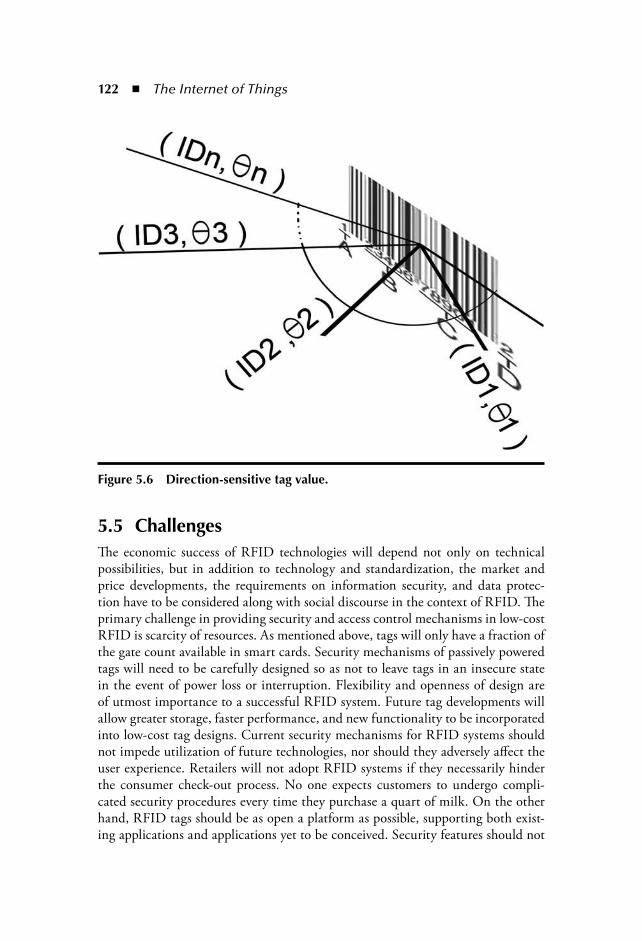
122 The Internet of Things
5.5 ChallengesThe economic success of RFID technologies will depend not only on technicalpossibilities, but in addition to technology and standardization, the market andprice developments, the requirements on information security, and data protec-tion have to be considered along with social discourse in the context of RFID. Theprimary challenge in providing security and access control mechanisms in low-costRFID is scarcity of resources. As mentioned above, tags will only have a fraction ofthe gate count available in smart cards. Security mechanisms of passively poweredtags will need to be carefully designed so as not to leave tags in an insecure statein the event of power loss or interruption. Flexibility and openness of design areof utmost importance to a successful RFID system. Future tag developments willallow greater storage, faster performance, and new functionality to be incorporatedinto low-cost tag designs. Current security mechanisms for RFID systems shouldnot impede utilization of future technologies, nor should they adversely affect theuser experience. Retailers will not adopt RFID systems if they necessarily hinderthe consumer check-out process. No one expects customers to undergo compli-cated security procedures every time they purchase a quart of milk. On the otherhand, RFID tags should be as open a platform as possible, supporting both exist-ing applications and applications yet to be conceived. Security features should not
Figure 5.6 Direction-sensitive tag value.

RFID Security: Threats and Solutions 123
interfere with the development of new applications by third parties. Many usefulconsumer applications could emerge from grass-roots development and should notbe impaired by proprietary or closed security mechanisms.
5.6 Conclusions and OutlookAs the RFID market expands, users will see the continued proliferation of RFIDtags built for highly specialized vertical markets, which means greater variety andthe consequent need to ensure interoperability. A great deal of research and devel-opment is currently under way in the RFID security field to mitigate both knownand postulated risks. Manufacturers, business managers, and RFID systems engi-neers continue to weigh the trade-offs between chip size, cost, functionality, secu-rity, and privacy with the bottom-line impact on business processes. In the comingmonths, security features supporting data confidentiality, tag-to-reader authentica-tion, optimized RF protocols, high-assurance readers, and secure system engineer-ing principles should become available. Security and privacy in RFID tags are notjust technical issues, important policy questions arise as RFID tags join to createlarge sensor networks and bring us closer to ubiquitous computing. With publicattention focused on the RFID landscape, security and privacy have moved to theforefront in RFID standards work and the results will be worth watching.
References [1] EPCTM Radio-Frequency Identity Protocols Class-1 Generation-2 UHF RFID Pro-
tocol for Communications at 860 MHz – 960 MHz, ver. 1.0.9. EPCglobal Inc., Jan.31, 2005. Available: http://www.epcglobalinc.org/.
[2] A. Juels, R.L. Rivest, and M. Szydlo. The blocker tag: Selective blocking of RFID tags for consumer privacy. In V. Atluri, ed. 8th ACM Conference on Computer and Communi-cations Security (Philadelphia, PA, November, 2001) pp. 103–111. ACM Press, 2003.
[3] M. Ohkubo, K. Suzuki, and S. Kinoshita. Efficient hash-chain based RFID privacy protection scheme. In International Conference on Ubiquitous Computing–Ubi-comp, Workshop Privacy: Current Status and Future Directions, 2004.
[4] A. Juels. Minimalist Cryptography for RFID Tags. 4th Conference on Securityin Comm. Networks (SCN), C. Blundo and S. Cimato, eds., Springer-Verlag,Heidelberg, Germany, 2004, 149–164.
[5] P. Golle, M. Jakobsson, A. Juels, and P. Syverson. Universal re-encryption for mixnets. In T. Okamoto, ed., RSA Conference Cryptographers Track (CT-RSA),vol. 2964 of Lecture Notes in Computer Science, pp. 163–178, 2004.
[6] S. Weis, S. Sarma, R. Rivest, and D. Engels. Security and privacy aspects of low-cost radio frequency identification systems. In D. Hutter, G. Muller, W. Stephan, andM. Ullmann, eds. International Conference on Security in Pervasive ComputingSPC 2003, vol. 2802 of Lecture Notes in Computer Science, pp. 454–469. Springer-Verlag, Heidelberg, Germany, 2003.

124 The Internet of Things
[7] D. Molnar and D. Wagner. Privacy and security in library RFID: Issues, practices, and architectures. In B. Pflitzmann and P. McDaniel, eds., ACM Conference onCommunications and Computer Security , pp. 210–219. ACM Press, 2004.
[8] D. Molnar, A. Soppera, and D. Wagner. A scalable, delegatable pseudonym protocol enabling ownership transfer of RFID tags. In B. Preneel and S. Tavares, eds. SelectedAreas in Cryptography, SAC 2005, Lecture Notes in Computer Science. Springer-Verlag, Heidelberg, Germany, 2005.
[9] A. Juels. Minimalist cryptography for low-cost RFID tags. In C. Blundo and S.Cimato, eds. The Fourth International Conference on Security in Communi-cation Networks SCN 2004, vol. 3352 of Lecture Notes in Computer Science,pp. 149–164. Springer-Verlag, Heidelberg, Germany, 2004.
[10] G. Avoine and P. Oechslin. A scalable and provably secure hash-based RFID protocol.In F. Stajano and R. Thomas, eds. The 2nd IEEE International Workshop on Per-vasive Computing and Communication Security Parsec 2005, pp. 110–114. IEEEComputer Society Press, Washington, D.C., 2005.
[11] D. Henrici and P. Muller. Tackling Security and Privacy Issues in Radio Frequency Identification Devices. In Ferscha A., Mattern F.: Pervasive Computing (Proceed-ings of PERVASIVE 2004, 2nd International Conference on Pervasive Computing)pp. 219–224. Springer-Verlag, Heidelberg, Germany, 2004.
[12] S. Garfinkel. An RFID Bill of Rights. Technology Review, p. 35, October 2002. [13] M. Rieback, B. Crispo, and A. Tanenbaum. RFID Guardian: A battery-powered
mobile device for RFID privacy management. In C. Boyd and J.M. Gonzalez Nieto,eds. Australian Conference on Information Security and Privacy – ACISP 2005,vol. 3574 of Lecture Notes in Computer Science, pp. 184–194. Springer-Verlag,Heidelberg, Germany, 2005.
[14] Certicom Security for RFID Product Authentication. http://www.certicom.com/index.php?action sol,rfid.
[15] Vandia Security Solutions. http://www.vandia.com/, referenced 2007. [16] S.E. Sarma. Personal correspondence, 2002.
Further Reading [1] R.J. Anderson and M.G. Kuhn. Low cost attacks on tamper resistant devices. In B.
Christianson, B. Crispo, T.M.A. Lomas, and M. Roe, Eds., Security ProtocolsWorkshop, vol. 1361 of Lecture Notes in Computer Science, 125–136. Springer-Verlag, Heidelberg, Germany, 1997.
[2] G. Avoine, E. Dysli, and P. Oechslin. Reducing time complexity in RFID systems. [3] S. Bono, M. Green, A. Stubblefield, A. Juels, A. Rubin, and M. Szydlo. Security
analysis of a cryptographically-enabled RFID device. In Proc. USENIX Security Sym-posium, July–August 2005.
[4] T. Dimitriou. A lightweight RFID protocol to protect against traceability and cloning attacks. In Proc. of SecureComm’05, Athens, Greece, August–September, 2005.
[5] K. Finkenzeller. RFID Handbook. John Wiley & Sons, New York, 1999.

RFID Security: Threats and Solutions 125
[6] K. Fishkin and J. Lundell. RFID in healthcare. In S. Garfinkel and B. Rosenberg,eds. RFID: Applications Security, and Privacy, pp. 211–228. Addison-Wesley,Reading, MA, 2005.
[7] S. Garfinkel and B. Rosenberg, eds. RFID Applications, Security, and Privacy.Addison-Wesley, Reading, MA, 2005.
[8] A. Juels. Strengthing EPC tags against cloning. In ACM Workshop on Wireless Secu-rity (WiSe). ACM Press, 2005.
[9] Ari Juels. RSA Security—RFID Security and Privacy: A Research Survey.[10] P. Peris-Lopez, J.C. Hernandez-Castro, J.M. Estevez-Tapiador, and A. Ribagorda.
An Efficient Mutual-Authentication Protocol for Low-cost RFID Tags. [11] RFID Journal. Online publication. Referenced 2005. [12] Texas Instruments gen-2 inlay data sheet, 2005. Referenced 2005 at: http://www.
ti.com/rfid/docs/manuals/.[13] I. Vajda and L. Buttyian. Lightweight authentication protocols for low-cost RFID tags.
In Proc. of UbiComp’03, Seattle, WA, 2003. [14] S.A. Weis. Radio-frequency identification security and privacy. Masters thesis, M.I.T.,
June 2003.


127
Chapter 6
RFID Specification Revisited
Pedro Peris-Lopez, Julio C. Hernandez-Castro, Juan M. Estevez-Tapiador, and Arturo Ribagorda
Contents6.1 Introduction ............................................................................................1286.2 Generation-2 Versus Generation-1 ...........................................................131
6.2.1 Read and Write Speed...................................................................1316.2.2 Robust Tag Counting ...................................................................1316.2.3 Dense Reader Operation...............................................................1326.2.4 Parallel Counting..........................................................................132
6.3 EPC Class-1 Generation-2 Specification ..................................................1326.3.1 Physical Layer ...............................................................................1336.3.2 Tag Identification Layer................................................................1336.3.3 Tag Memory .................................................................................1336.3.4 Tag States and Slot Counter..........................................................1356.3.5 Managing Tag Populations ...........................................................137
6.4 Risks and Threats.....................................................................................1376.5 Cryptographic Primitives.........................................................................138
6.5.1 Hash Functions ............................................................................1386.5.2 Ciphers .........................................................................................1396.5.3 Pseudorandom Number Generators ..............................................139
6.6 Security Analysis and Open Issues...........................................................1406.6.1 Inventory Procedure .....................................................................1406.6.2 Access Procedures .........................................................................142

128 The Internet of Things
RFID (Radio Frequency Identification) is the name given to all technologies thatuse radio waves to automatically identify and account transactions on people, ani-mals, or objects [1] by means of electromagnetic proximity [2]. RFID technologyis not new, as one of its first usages dates from 1940 where a RFID-based Iden-tification Friend or Foe (IFF) system was used [3]. There are multiple standardsrelated to RFID technology. In this chapter, the Electronic Product Code (EPC)Class-1 Generation-2 is examined. This standard can be considered as the “univer-sal” standard for Class-1 RFID tags. Class-1 RFID tags are very limited both intheir computational and storage capabilities. Because of these severe restrictions,the usage of standard cryptographic primitives is not possible. However, RFIDtags are susceptible to attacks also found in other technologies, such as wireless,bluetooth, smart-cards, etc. Therefore, once the EPC Class-1 Generation-2 speci-fication is explained, a security analysis will reveal its weak points. Furthermore,current proposals to enhance its security level are presented and analyzed. Finally,the chapter is concluded identifying some open research issues to increment thesecurity of low-cost RFID tags.
6.1 IntroductionRFID systems are already used for a large number of applications related to objectidentification: retail stock management, access control, animal tracking, theft pre-vention, sports timing, medical applications, etc. In fact, RFID applications areonly limited by human imagination. However, a number of security questions arestill open. As it has been shown by a recent European Union (EU)-funded public
6.6.2.1 Write, Kill, and Access Commands ................................1426.6.2.2 Read Command .............................................................1446.6.2.3 Lock Command .............................................................1446.6.2.4 BlockWrite and BlockErase Commands .........................146
6.7 EPC Class-1 Generation-2+......................................................................1476.7.1 Strengthening EPC Tags...............................................................147
6.7.1.1 Basic TagAuth Protocol ..................................................1486.7.1.2 Enhanced TagAuth Protocol ..........................................148
6.7.2 Shoehorning Security into the EPC Standard...............................1496.7.3 Enhancing Security of EPC-C1G2 ...............................................1496.7.4 Mutual Authentication Protocol ................................................... 151
6.7.4.1 Initialization Phase ......................................................... 1516.7.4.2 The (n+1) Authentication Phase ...................................... 151
6.8 Conclusions ............................................................................................. 152References ......................................................................................................... 153
RFID Specification Revisited 129
consultation [4], most of the participants are seriously concerned about privacyimplications and tracking, or the violation of location privacy, which was the mostimportant issue.
RFID is a relatively heterogeneous radio technology with a significant numberof associated standards. As in Peris-Lopez et al. [5], standards can be classifiedaccording to five main categories: contactless integrated circuit cards, RFID inanimals, item management, near field communication (NFC), and EPC. Figure 6.1summarizes the most important of those.
The benefits of standards are clear and assumed by almost everyone. The growthof any new technology is in many cases due in part to the establishment of openstandards. In 2003, there was a clear lack of harmonization and major RFID ven-dors offered mainly proprietary systems. Fortunately, things are quickly changing.Today, EPCglobal [6] and ISO [7] join forces to publicize and harmonize the useof RFID technology.
The EPCglobal is a joint venture between EAN International and the UniformCode Council (UCC). EPCglobal fulfills the industry’s need for an effective RFIDnetwork standard with its EPC (Electronic Product Code) Network. Within EPC-global, the Hardware Action Group (HAG) develops specifications for hardwarecomponents of the EPC Network, including tags and readers. The EPC systemdefines four RFID tag classes:
1. Class-1: Identity Tags. Passive backscatter tags with the following mini-mum features:
An Electronic Product Code (EPC) identifier A tag identifier (TID) A kill function that permanently disables the tag Optional password-protected access control and optional user memory
2. Class-2: Higher functionality tags. Passive tags with all the aforemen-tioned features and also including the following:
An extended TID Extended memory Authenticated access control Additional features (TBD), as will be defined in the Class-2specification
3. Class-3: Semipassive tags with all the aforementioned features and alsoincluding the following:
An integral power source An integrated sensing circuitry
4. Class-4: Active tags with all the aforementioned features and also includ-ing the following:
Tag-to-tag communications Active communications Ad hoc and networking capabilities
−−−−
−−−−
−−
−−−

130 The Internet of ThingsA
NS
I
FCC
ER
OE
CC
ETSI
ISO
EPC
Co
nta
ctle
ssIn
teg
rate
dC
ircu
itC
ard
s
An
imal
Iden
tifi
cati
on
Item
Man
agem
ent
EP
C
NF
CE
TS
ITS
10
2.1
90
ISO
18
09
2E
CM
A34
0N
FC
IP-1
NF
CIP
-2
EP
C G
en-1
Tag
Dat
a S
tan
dar
ds
Ver
s. 1
.3E
PC
RF
ID P
roto
cols
Cla
ss -
1 G
en-2
Ver
s. 1
.09
EP
C R
eact
or
Pro
toco
l S
tan
dar
d V
ers.
1.0
EP
C M
idd
lew
are
AL
E S
pe
cifi
cati
on
Ver
s.1
.0E
PC
ON
S S
pe
cifi
cati
on
Ver
s. 1
.0
ISO
18
00
0
ISO
11
784
ISO
11
78
5IS
O14
22
3
ISO
10
53
6IS
O1444
3IS
O1
56
93
ISO
634
6IS
O 7
81
6IS
O 14
81
6IS
O 1
56
91
ISO
15
69
2IS
O 1
73
58
ISO
17
36
3IS
O 1
73
64
ISO
17
36
5IS
O 1
63
66
ISO
17
36
7IS
O 1
03
74
.2
Figu
re6.
1R
FID
sta
ndar
ds.

RFID Specification Revisited 131
6.2 Generation-2 Versus Generation-1One of the most important standards proposed by EPCglobal is the EPCglobalClass-1 Gen-2 RFID specification [8]. This standard was adopted by EPCglobalin 2004 and was sent to ISO. Eighteen months later (March to April 2006), it wasratified by ISO and published as an amendment to its 18000-6 standard.
These specifications provide a great advance in consolidating the adoption ofRFID technology [9]. Where previously there were several specifications, such asEPC Class-1 and EPC Class-0, a single ultra high frequency (UHF) specificationis now established. In order to provide a worldwide deployment, emerging UHFregulations in different regions have been taken into account. Additionally, the bestfeatures of the preceding specifications have been improved, and a range of futureapplications including higher function sensor tags have been foreseen.
6.2.1 Read and Write SpeedGeneration-1 provides a single communication speed, providing satisfactory speedand adequate robustness for most applications. On the other hand, four differentcommunication speeds are available in Gen-2 to provide more flexibility for dif-ferent operational environments. Gen-2 tags have a maximum theoretical readingspeed of around 1,000 tags per second (when insulated from RF noise), but in verynoisy environments that speed is reduced to around 100 tags/sec. The read speed ofGen-2 is then about twice as fast as in Gen-1 in real conditions with average readrates of around 500 tags per second.
Furthermore, Gen-2 specifies the speed at which tags can be programmed. Thespecification dictates that tags should be writable at a minimum rate of about 5 persecond, setting 30 tag/sec as the objective value in optimum conditions.
6.2.2 Robust Tag CountingTags compliant with Gen-1 specification are singulated by means of binary treewalking protocols with persistent sleep/wake states. The Gen-2 specification arebased on the principle that tags experiencing brief moments of power can be read.Thusly, the Q protocol, which is based on simple query/acknowledgment exchangesbetween reader and tags, is employed. Q is a parameter that a reader uses to regulatethe probability of tag response. Briefly, a reader sends a query to a tag and the tagloads a Q-bit random number (or pseudo-random number) into its slot counter.Tag responds with a random number when the value in its slot counter is fixed tozero. The reader then sends an acknowledgement that includes the tag’s randomnumber, which then sends back its ID (i.e., EPC). The process continues until alltags in the reader’s field have been counted.
132 The Internet of Things
In Gen-1, tags are switched to sleep mode after they have been read, easing thereading of tags that have not yet been counted. To begin a new count, a wake-upmessage is sent to tags in order for them to be ready for reading. Multiple wake-up, count, and sleep cycles are necessary to ensure that all tags in a reader fieldhave been read. Gen-2 refines this process by introducing a dual state, avoidingthe necessity of a wake-up command. Under this approximation, tags change theirstate each time they are read. As the reader counts tags in “A” state, these changeautomatically to “B” state, and vice versa. Gen-2 repeats counts of A and B untilall tags have been identified. Therefore, these two mechanisms allow both to incre-ment the reading speed and to make sure all tags have been counted.
6.2.3 Dense Reader OperationIf there are many readers operating and querying in close proximity at the sametime, this can drown out the weak responses of tags. In the United States, fre-quency hopping is used, as there are no severe bandwidth requirements in the UHFband. In Europe, the band available to RFID is relatively narrow, so this approachis not possible. Readers are required to “listen before talking.” First they determinethat the channel is not already in use; only then can they start communication.
Gen-2 tries to improve its features under dense reader operation in several ways.First, the available RF bandwidth is used as efficiently as possible, only minimal datais exchanged between readers and tags. Second, Gen-2 provides new radio signal-ing techniques, which easily allows isolatation of tag response, even in noisy condi-tions. Therefore, “Miller subcarrier” or “FM0” are employed. Third, three modes ofoperation are available: single reader, multireader and dense reader. Finally, Gen-2verifies data as in Gen-1 specification to ensure accurate reads in noisy environ-ments and adds a feature that confirms when tags have been correctly written.
6.2.4 Parallel CountingIt is possible that several readers can simultaneously communicate with the sametag. Under this situation, a tag might change its state in the middle of anotherreader’s query, causing the loss of the tag by the second reader. To solve this prob-lem, tag support “sessions” allowing a single tag to communicate with two or morereaders. Four logical sessions are available to be assigned to readers.
6.3 EPC Class-1 Generation-2 SpecificationThe EPC Class-1 Generation-2 specification [8], in the following EPC-C1G2,defines the physical and logical requirements for RFID systems operating in the860 to 960 MHz frequency range. These systems are made up of two main compo-nents: interrogators, also known as readers; and tags, also known as labels.
RFID Specification Revisited 133
Modulating a RF signal (860 to 960 MHz), a reader transmits information toa tag. As tags are passive, all of their operating energy is received from the reader’sRF waveform. Indeed, both information and operating energy are extracted fromthe signal sent by the reader.
Furthermore, as tags do not have a power source, tags can only answer after amessage is sent by the reader. These kind of systems are known as Interrogator TalkFirst (ITF). A reader receives information from a tag by transmitting a continuoswave RF signal to the tag. The tag backscatters a signal to the reader by means ofthe modulation of the reflection coefficient of its antenna. Communications arehalf-duplex, so the reader talks and the tag listens, or vice versa.
6.3.1 Physical LayerA reader sends information to one or more tags by modulating a RF carrier using dou-ble-sideband amplitude shift keying (DSB-ASK), single-sideband amplitude shift key-ing (SSB-ASK), or phase reversal amplitude shift keying (PS-ASK) using pulse intervalencoding (PIE) format. Tags receive their operating power from this RF signal.
In order to receive information from a tag, readers transmit an unmodulatedRF carrier and listen for a backscattered replay. Tags send information by back-scatter, modulating the amplitude/phase of the RF carrier. The encoding format iseither a FM0 or Miller-modulated subcarrier.
6.3.2 Tag Identification LayerA reader interacts with tags using three basic operations:
1. Select: The operation of choosing a subset of the tag population for inven-tory and access. Working with databases, this operation is similar to select-ing records.
2. Inventory: The operation of identifying tags. Concretely, after the exchangeof several messages (inventory round), the tag sends to the reader the proto-col control (PC), EPC, and a cyclic redundancy check (CRC)-16 value. Aninventory round operates in one and only one session at a time.
3. Access: The operation of communicating (reading from and/or writing to)with a tag, which is comprised of multiples commands. Tags have to beunequivocally identified before access.
6.3.3 Tag MemoryTag memory is separated logically into four banks, as illustrated in Figure 6.2.
1. Reserved memory (Bank 00): This area of memory shall contain the killand access passwords. Unless this memory locations have nonzero values,
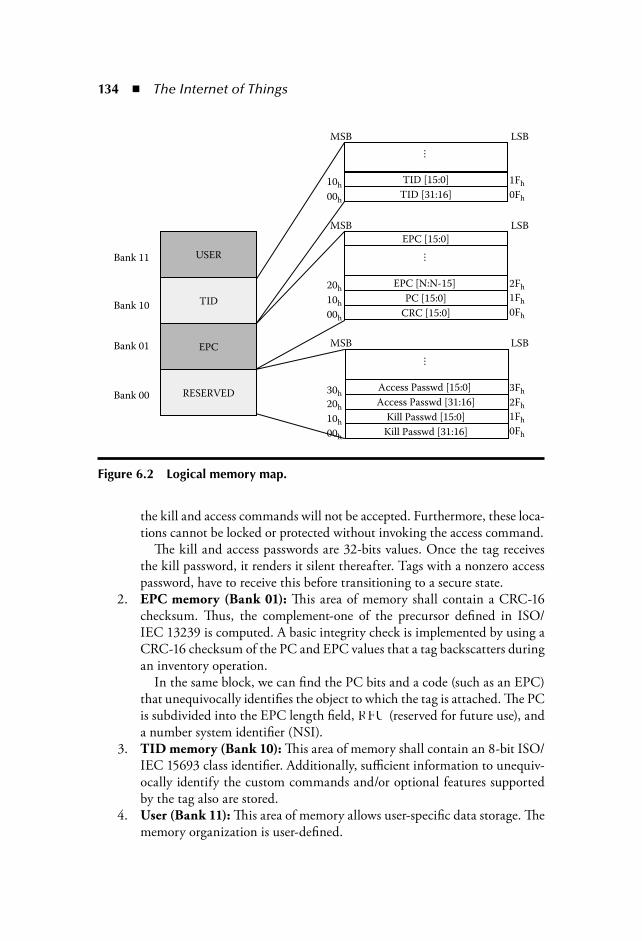
134 The Internet of Things
the kill and access commands will not be accepted. Furthermore, these loca-tions cannot be locked or protected without invoking the access command.
The kill and access passwords are 32-bits values. Once the tag receivesthe kill password, it renders it silent thereafter. Tags with a nonzero accesspassword, have to receive this before transitioning to a secure state.
2. EPC memory (Bank 01): This area of memory shall contain a CRC-16checksum. Thus, the complement-one of the precursor defined in ISO/IEC 13239 is computed. A basic integrity check is implemented by using aCRC-16 checksum of the PC and EPC values that a tag backscatters duringan inventory operation.
In the same block, we can find the PC bits and a code (such as an EPC)that unequivocally identifies the object to which the tag is attached. The PCis subdivided into the EPC length field, RFU (reserved for future use), anda number system identifier (NSI).
3. TID memory (Bank 10): This area of memory shall contain an 8-bit ISO/IEC 15693 class identifier. Additionally, sufficient information to unequiv-ocally identify the custom commands and/or optional features supportedby the tag also are stored.
4. User (Bank 11): This area of memory allows user-specific data storage. Thememory organization is user-defined.
USER
RESERVED
EPC
TID
Bank 11
Bank 10
Bank 01
Bank 00
MSB
10h1Fh
0Fh
1Fh
2Fh
0Fh
1Fh
2Fh
3Fh
0Fh
00h
20h
10h
00h
20h
30h
10h
00h
LSB
LSB
LSB
MSB
MSB
…
CRC [15:0]
PC [15:0]
EPC [N:N-15]
EPC [15:0]
TID [31:16]
TID [15:0]
Kill Passwd [15:0]
Access Passwd [31:16]
Access Passwd [15:0]
Kill Passwd [31:16]
……
Figure 6.2 Logical memory map.
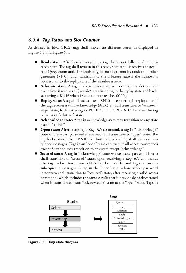
RFID Specification Revisited 135
6.3.4 Tag States and Slot CounterAs defined in EPC-C1G2, tags shall implement different states, as displayed inFigure 6.3 and Figure 6.4.
Ready state: After being energized, a tag that is not killed shall enter aready state. The tag shall remain in this ready state until it receives an accu-rate Query command. Tag loads a Q-bit number from its random numbergenerator (RNG), and transitions to the arbitrate state if the number isnonzero, or to the replay state if the number is zero.Arbitrate state: A tag in an arbitrate state will decrease its slot counterevery time it receives a QueryRep, transitioning to the replay state and back-scattering a RN16 when its slot counter reaches 0000h.Replay state: A tag shall backscatter a RN16 once entering in replay state. Ifthe tag receives a valid acknowledge (ACK), it shall transition to “acknowl-edge” state, backscattering its PC, EPC, and CRC-16. Otherwise, the tagremains in “arbitrate” state.Acknowledge state: A tag in acknowledge state may transition to any stateexcept “killed.”Open state: After receiving a Req_RN command, a tag in “acknowledge”state whose access password is nonzero shall transition to “open” state. Thetag backscatters a new RN16 that both reader and tag shall use in subse-quence messages. Tags in an “open” state can execute all access commandsexcept Lock and may transition to any state except “acknowledge”.Secured state: A tag in “acknowledge” state whose access password is zeroshall transition to “secured” state, upon receiving a Req_RN command.The tag backscatters a new RN16 that both reader and tag shall use insubsequence messages. A tag in the “open” state whose access passwordis nonzero shall transition to “secured” state, after receiving a valid accesscommand, which includes the same handle that it previously backscatteredwhen it transitioned from “acknowledge” state to the “open” state. Tags in
Select
Inventory
Access
Reader
Tags
Ready
Arbitrate
Reply
Acknowledged
Open
Secured
Killed
State
Figure 6.3 Tags state diagram.
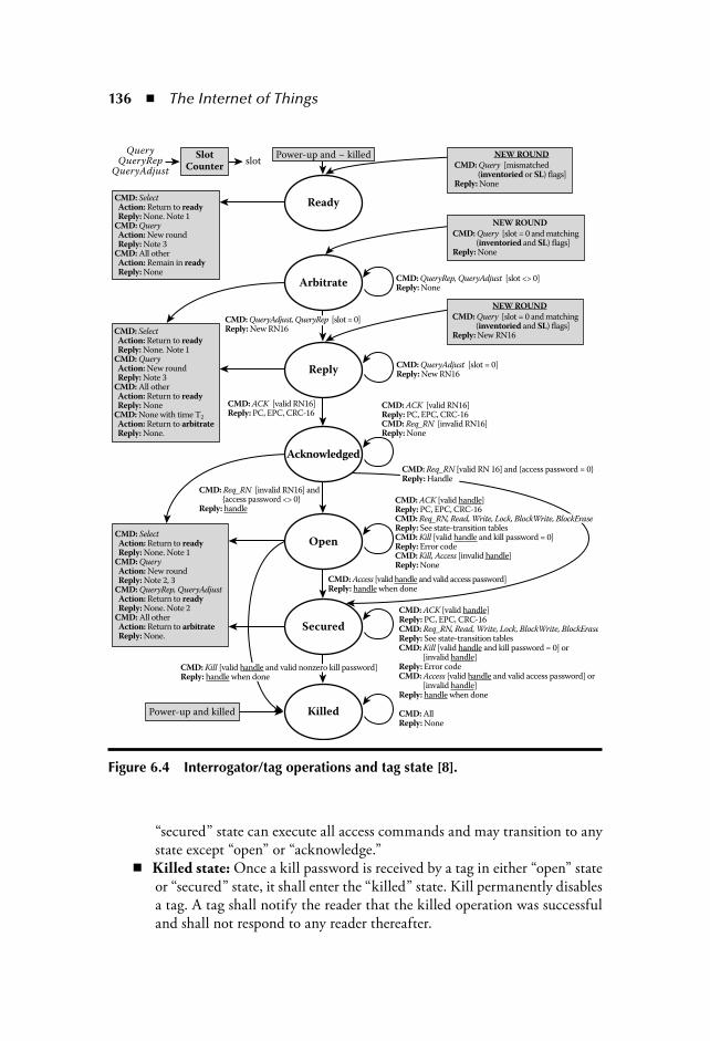
136 The Internet of Things
“secured” state can execute all access commands and may transition to anystate except “open” or “acknowledge.”Killed state: Once a kill password is received by a tag in either “open” stateor “secured” state, it shall enter the “killed” state. Kill permanently disablesa tag. A tag shall notify the reader that the killed operation was successfuland shall not respond to any reader thereafter.
Ready
Reply
Acknowledged
Open
Secured
Killed
Arbitrate
Power-up and ~ killed
Power-up and killed
SlotCounter
CMD: Select Action: Return to ready Reply: None. Note 1CMD: Query Action: New round Reply: Note 3CMD: All other Action: Remain in ready Reply: None
CMD: Select Action: Return to ready Reply: None. Note 1CMD: Query Action: New round Reply: Note 3CMD: All other Action: Return to ready Reply: NoneCMD: None with time T2
Action: Return to arbitrate Reply: None.
CMD: Select Action: Return to ready Reply: None. Note 1CMD: Query Action: New round Reply: Note 2, 3CMD: QueryRep, QueryAdjust Action: Return to ready Reply: None. Note 2CMD: All other Action: Return to arbitrate Reply: None.
CMD: ACK [valid handle]Reply: PC, EPC, CRC-16CMD: Req_RN, Read, Write, Lock, BlockWrite, BlockEraseReply: See state-transition tablesCMD: Kill [valid handle and kill password = 0] or [invalid handle]Reply: Error codeCMD: Access [valid handle and valid access password] or [invalid handle]Reply: handle when done
CMD: AllReply: None
CMD: ACK [valid handle]Reply: PC, EPC, CRC-16CMD: Req_RN, Read, Write, Lock, BlockWrite, BlockEraseReply: See state-transition tablesCMD: Kill [valid handle and kill password = 0]Reply: Error codeCMD: Kill, Access [invalid handle]Reply: None
NEW ROUND
CMD: Query [slot = 0 and matching (inventoried and SL) flags]Reply: New RN16
CMD: QueryRep, QueryAdjust [slot <> 0]Reply: None
CMD: QueryAdjust [slot = 0]Reply: New RN16
CMD: ACK [valid RN16]Reply: PC, EPC, CRC-16CMD: Req_RN [invalid RN16]Reply: None
CMD: Req_RN [invalid RN16] and {access password <> 0}Reply: handle
CMD: ACK [valid RN16]Reply: PC, EPC, CRC-16
CMD: QueryAdjust, QueryRep [slot = 0]Reply: New RN16
NEW ROUND
CMD: Query [mismatched (inventoried or SL) flags]Reply: None
NEW ROUND
CMD: Query [slot = 0 and matching (inventoried and SL) flags]Reply: None
CMD: Kill [valid handle and valid nonzero kill password]Reply: handle when done
slotQuery
QueryRepQueryAdjust
CMD: Access [valid handle and valid access password]Reply: handle when done
CMD: Req_RN [valid RN 16] and {access password = 0}Reply: Handle
Figure 6.4 Interrogator/tag operations and tag state [8].

RFID Specification Revisited 137
Tags shall implement a 15-bit slot counter. Once a Query or QueryAdjust commandis received, a tag shall load into its slot counter a value between 0 and 2Q 1 obtainedfrom a tag’s pseudorandom number generator (PRNG). Q is a integer in the range (0,15). A Query specifies Q, and a QueryAdjust may modify Q from the prior Query.
6.3.5 Managing Tag PopulationsAs shown in Figure 6.3, tag populations are managed using three basic opera-tions. Each of these operations comprise one or more commands. The operationsare defined as follows:
1. Select: The process that allows a reader to select a subset of the tag populationfor inventory and access. The select command is Select. A reader may use oneor more Select commands to select a particular tag previous to inventory.
2. Inventory: The process that allows a reader to identify a tag. The inventoryoperation is started by transmitting a Query command in one of the foursessions that the tag can handle. One or more tags may replay. The readerisolates a single tag response and requests the PC, EPC, CRC-16 from thetag. An inventory round can only operate one session at a time. The inven-tory command set is comprised of the following commands: Query, Query-Adjust, QueryRep, ACK, NACK. All of these commands are mandatory.
3. Access: The process that allows a reader to interact (read from or writeto) with individual tags. Tags have to be unequivocally identified priorto access. There are multiple access commands, some of which employ aone-time, pad-based cover coding in the R T link. The set of accesscommands is composed of the following mandatory commands: Req_RN,Read, Write, and Lock. Additionally, there are other optional commandsdescribed in the specification: Access, Blockwrite, and BlockErase.
6.4 Risks and ThreatsOne of the main problems that ubiquitous computing has to solve before it is widelydeveloped is privacy [10]. Products labeled with insecure tags could reveal sensitiveinformation when queried by readers. Readers frequently are not authenticated andtags usually answer in a complete transparent way. Moreover, even if we assumethat tag’s contents are secure, tracking (violation of location privacy) protection isnot guaranteed. Tags usually answer with the same identifier. These predictable taganswers allow a third party to establish an association between tags and their own-ers. Even if tags only contain product codes, rather than a unique serial number,tracking can still be possible by using an assembly of tags (constellation) [11].
Although the two problems mentioned above are the most important securityquestions that arise in RFID technology, there are some others worth mentioning:
Physical attacks: In order to mount these attacks, it is necessary to manip-ulate tags physically, generally in a laboratory. Some examples of physical

138 The Internet of Things
attacks are probe attacks, material removal through shaped charges orwater etching, radiation imprinting, circuit disruption, and clock glitch-ing, among others.Denial of Service (DOS): A common example of this type of attack inRFID systems is the signal jamming of RF channels.Counterfeiting: Attacks that consist in modifying the identity of an itemby means of tag manipulation.Spoofing: An attacker is able to successfully impersonate another, forexample, in a man-in-the-middle attack.Eavesdropping: Attacks when unintended recipients are capable of inter-cepting and reading messages.Traffic analysis: The process of intercepting and examining messages inorder to extract information from patterns in communication. It can beperformed even when the messages are encrypted and cannot be decrypted.In general, the greater the number of messages observed, the more informa-tion that can be inferred from the traffic.
6.5 Cryptographic PrimitivesTraditional cryptographic primitives exceed the capabilities of low-cost RFID tags,such as those compliant with EPC-C1G2. The required hardware complexity ofthese devices may be weighted up by its circuit area or the number of equivalentlogic gates. At most, around 4 K gates are assumed to be devoted to security-relatedtasks [12].
6.5.1 Hash FunctionsThe best implementation of SHA-256 requires around 11 K gates and 1,120 clockcycles to perform a hash calculation on a 512-bit data block [13]. As the number ofneeded resources are quite higher than those of a low-cost RFID tag, it may seemnatural to propose the use of smaller hash functions. However, functions, such asSHA-1 (8.1 K gates, 1,228 clock cycles) or MD5 (8.4 K gates, 612 clock cycles),cannot be fitted in a low-cost tag [13]. Recently, some authors suggested the usageof a new “universal hash function” [14]. Although this solution only needs around1.7 K gates, a deeper security analysis is needed and has not yet been accomplished.Furthermore, this function has only a 64-bit output, which does not guarantee anappropriate security level because finding collisions is a relatively easy task due tothe birthday paradox* (around 232 operations).
* The birthday paradox states that if there are 23 people in a room, then there is a slightly morethan 50:50 chance that at least two of them will have the same birthday.

RFID Specification Revisited 139
6.5.2 CiphersAs traditional ciphers (DES, AES, etc.) exceed by large the computational andstorage capabilities of constrained devices [15,16], some authors are focusing onefficient implementations of these ciphers. We can point out the interesting work ofFeldhofer et al. who have proposed an efficient AES implementation (3,400 gates,12 kbps) [16,17].
Another interesting work is the eSTREAM Project, which tries to identifynew secure stream ciphers. The profile 2 is focused on stream ciphers for hardwareapplications with restricted resources, such as limited storage, gate count, or powerconsumption. Two of the candidates that have been selected for the Phase 3 (profile 3)are Grain and Trivium. Grain (2,133 gates, 100 kbps) and Trivium (3,000 gates,100 kbps) are synchronous stream ciphers proposed by Hell et al. [18,19] and DeCanniere et al. [18,20]. Despite the fact that these ciphers may fit in a low-costRFID tag, the security of these ciphers is still an open question, as shown by theattacks [21,22] and the publication of amendments and different versions (Grain,Grain 1.0, Grain-128) [23].
6.5.3 Pseudorandom Number GeneratorsThe need for random and pseudorandom numbers arises in many cryptographicapplications. In fact, the usage of PRNGs in RFIDs has been proposed since theirvery beginning. In 2003, Weis et al. [11] proposed the randomized hash-lockingscheme, based on a hash function and a random number generator, in order to pre-vent tracking, but limiting its applicability to small tag populations [24]. Molnarand Wagner [25] proposed a simple protocol for enhancing passwords in RFIDtags. There are other papers where the use of a PRNG has been proposed [26–30].Nowadays, the used of a PRNG has been ratified by EPCglobal (EPC-C1G2) andISO (ISO/IEC 18006-C). On the contrary, tags compliant with EPC-C1G2 donot support onboard conventional encryption, hash functions, or any other kind ofcryptographic primitive.
According to the EPC-C1G2, tags shall generate 16-bit random or pseudoran-dom numbers (RN16), and shall have the ability to extract Q-bit subsets from aRN16 to preload into its slot counter. Additionally, tags should be able to temporar-ily store at least two RN16s while powered, e.g., a handle and a 16-bit cover-codeduring password transactions. The generator (RN16) should meet the followingrandomness criteria:
Probability of a single RN16: The probability that any RN16 drawn fromthe RNG has value RN16 = j, for any j shall be bounded by 0.8/216 < P(RN16= j) < 1.25/216.Probability of simultaneously identical sequences: For a tag popula-tion of up to 10,000 tags, the probability that any of two or more tags
140 The Internet of Things
simultaneously generating the same sequence of RN16s shall be less than0.1 percent, regardless of when the tags are energized.Probability of predicting an RN16: An RN16 drawn from a tag’s RNG10 ms after the end of Tr, shall not be predictable with a probability greaterthan 0.025 percent if the outcomes of prior draws from RNG, performedunder identical conditions are known.
6.6 Security Analysis and Open IssuesIn this section, we see in detail the messages interchanged in the different opera-tions between tags and readers. Once the procedures has been understood, thesecurity faults can be easily identified.
6.6.1 Inventory ProcedureA Query initiates an inventory round and decides which tags participate in theround. After receiving the Query, tags shall pick up a random value in the range (0,2Q 1), and load this value into their slot counter. Tags that pick up a nonzero valueshall transition to the arbitrate state and await a QueryAdjust or QueryResp com-mand. Assuming that a single tag answers (slot_counter = 0), the query responsealgorithm proceeds as follows:
T R: The tag backscatters an RN16 and enters in replay state.R T: The reader acknowledges the tag with an ACK containing the sameRN16.T R: The acknowledged tag transitions to the acknowledged state, andbackscatters its PC, EPC, and CRC-16.R T: The reader sends a QueryAdjust or QueryRep, so the identified taginverts its inventory flag (i.e., A B or B A) and transitions to the readystate.
The security of this procedure is nonexistent. Imagine a scenario where a pas-sive eavesdropper is listening to the channel. Under these conditions, the followingsecurity drawbacks are:
Tags do not transmit the EPC in a secure way. Instead, the EPC is transmit-ted in plain-text. So, one of the most important concerns about the use ofRFID technology is not accomplished. In other words, the privacy infor-mation of the tag is easily jeopardized.

RFID Specification Revisited 141
Every time a tag is interrogated, it always transmits the same EPC. Dueto the fact that the EPC transmitted by a tag is fixed, a tag may be associ-ated with its holder allowing its tracking. Suppose that your watch hasa tag compliant with the EPC-C1G2. An attacker may place readers inyour favorite entertainment places: cinemas, pubs, shops, etc. During twomonths, the attacker’s readers store the day and hours when you stay atthese places. Then, the attacker collects all this information, obtaining aconsumer profile of you, which is very valuable information to a great num-ber of companies. It is only an example of how privacy location may becompromised. Therefore, another of the citizen concerns about the implan-tation of RFID technology is again questioned.
The above scenario shows how privacy and location privacy is not guaranteedeven under a weak attack scenario where there is a passive eavesdropper. To avoidthese two connected problems, researchers propose the use of pseudonyms. In gen-eral terms, a pseudonym is a fictitious name. In RFID context, a pseudonym isinterpreted as an anonymized static identifier. However, under these conditionsonly privacy is guaranteed, as private information is passed on the channel. Anadditional requirement is needed to prevent an attacker from being able to tracka holder’s tag. Thusly, every time the tag is interrogated, the tag has to transmit anew, fresh pseudonym.
The most commonly found solution in the literature consists of repeatedlyapplying a hash function to the static identifier (i.e., pseudonymn = hashn(EPC)).Since the work of Sarma [31] in 2002, there has been a huge number of solutionsbased on this idea [32–36]. Other authors have proposed using both hash functionsand pseudorandom numbers generators [27,29].
The use of pseudonyms may be a good and interesting solution. However, hashfunctions have not been ratified by the EPC-C1G2 specification. As we have shownabove, standard hash functions exceed by far the capabilities of low-cost RFID-tags. Therefore, an interesting issue may be to design efficient and lightweight hashfunctions for RFID environments.
In another different direction, other authors propose the use of lightweightcryptography. Juels [37] proposal is based on using memory: Tags store a short listof random identifiers or pseudonyms (known by authorized verifiers to be equiva-lent). Each time the tag is queried, it emits the next pseudonym in the list. Onthe other hand, Vajda and Buttyán et al. [38–40] proposals are based on usingefficient operators (bitwise or, and, xor and sum mod 2m) to design new ultra-light-weight cryptographic primitives. Although these proposals present some securityproblems, they stand for a great advance in the research area of securing low-costRFID tags. In fact, some interesting ideas may be extracted for the incoming Gen-3specification.

142 The Internet of Things
6.6.2 Access ProceduresAfter acknowledging a tag, a reader may want to access the tag. The access com-mand set comprises Req_RN, Read, Write, Kill, Lock, Access, Blockwrite, and Bloc-kerase. The above commands can be computed under the following conditions:
Command State
Req_RN Acknowledged, open or secured Read Secured Write Secured BlockWrite Secured BlockErase Secured Acess Open or secured Kill Open or secured Lock Secured
Note that Read, Write, Blockwrite, and BlockErase commands also may beexecuted from the open state when allowed by the lock status of the memorylocation.
A reader starts an access to a tag in the acknowledged state as set out below:
R T: The reader sends a Req_RN to the acknowledged tag.T R: The tag generates and stores a new RN16 (denoted handle). Then,the tag backscatters the handle, and transitions to open state if its accesspassword is nonzero, or to the secured state if its access password is zero.R: Now or sometime later, the reader may start further access commands.
All access commands sent to a tag (in open or secured state) include the handleas a parameter. The tag shall verify the handle every time an access command isreceived. Access commands with an incorrect handle are ignored. Tag’s answersshould include the handle, whose value is fixed for the entire duration of an accesssequence.
Tags and readers can communicate indefinitely in the open and secured states.If the reader wants to finish communication, one of the followings messages wouldhave to be sent: Query, QueryAdjust, QueryRep, or NAK.
6.6.2.1 Write, Kill, and Access Commands
Everytime a Write, Kill, or Access command is sent to a tag, a 16-bit word (eitherdata or half-password) is transmitted over the channel. As confidential informationis sent, the reader “obscures” it by means of a cover code. In general terms, to covercode data or a password, the reader first requests a random number from the tag.

RFID Specification Revisited 143
The reader computes a bitwise xor of the word with this random number, and trans-mits the cover code string to the tag. Finally, the tag uncovers the received wordby performing a bitwise xor with the original random number. As described in thespecification, the following sequence of messages are exchanged:
R T: The reader sends a Req_RN to the acknowledged tag.T R: The tag generates a new RN16 and backscatters it to the reader.R T: The reader computes a 16-bit cipher-text, which is composed of thebitwise xor of the 16-bit word to be transmitted with the new RN16. Thereader sends a command to the reader, which includes as a parameterthe cipher-text and the handle.T R: The tag decrypts the received cipher-text performing a bitwise xorof it with the original RN16.
Kill and access passwords are 32-bits length. Therefore, to kill or access a tag, areader shall follow a multistep procedure: The first containing the 16 most signifi-cant bits (MSB) of the kill or access password xored with a RN16, and the secondcontaining the 16 least significant bits (LSB) of the kill or access password xoredwith a different RN16.
The security margin of a protocol using a 16-bit PRNG is usually bounded by1/216. Furthermore, the access and kill password are 32-bit values. The use of 32-bitsrandom numbers would avoid the multistep procedure for using the access, kill, andwrite command. We recommend the use of 32-bits PRNG, which increases its secu-rity level and provides greater flexibility. Therefore, the design of lightweight 32-bitsPRNG can be considered as an interesting open issue in RFID security. This PRNGhas to obey the randomness criteria specified in the EPC-G1G2 standard [8] and thesevere computational and storing requirements for low-cost RFID tags.
The RFID channel asymmetry does not prevent the listening of the backwardchannel (tag-to-reader channel) by an attacker. Indeed, the security of the abovemechanisms can be easily jeopardized even by a passive eavesdropper. Under thisscenario, the attacker can obtain the random number (RN16) sent by the tag(answer to Req_RN message). Once obtained, the attacker can decrypt the messagesent by the reader using a simple xor. Therefore, the access password, kill password,or send data can be easily acquired by means of listening to the channel and per-forming a bitwise xor. Summarizing, the cover coding does not provide any kind ofsecurity protection to data or passwords.
A naivé solution to protect data and passwords would be the use of conventionalencryption. However, standard cryptographic ciphers lie beyond the capabilitiesof low-cost RFID tags. So, an open issue is the designing of new secure ciphersconforming to the severe restrictions of these environments. Another possible solu-tion may consist on more sophisticated challenge-response protocols, such as theultra-lightweight mutual authentication protocols proposed by Peris-Lopez et al.in [39,40].

144 The Internet of Things
6.6.2.2 Read Command
Read allows a reader to read part or all of the tag’s reserved, EPC, TID, or usermemory. A read command has the following fields:
MemoryBank: Specifies whether the reader accesses reserved, EPC, TID,or user access memory.WordPtr: Specifies the starting word address for the memory read, wherewords are 16-bit in length.WordCount: Specifies the number of 16-bit words to be read.
The Read command also includes the tag’s handle and a CRC-16. Before receiv-ing a Read command, the tag first verifies that all memory words exist and none areread-locked. Second, the tag backscatters a header (a 0-bit), the requested memorywords, and its handle.
The information exchanged between readers and tags is transmitted in plain-text. So, if the tag requests access to private information, it could be obtained byan attacker listening to the channel. In the case of the access password being equalto zero, the Reading command can be accomplished from the open state. This willimply that an adversary may gain access to the tag’s data without prior authentica-tion. Once the tag is in open state, an attacker may send messages to the tag tryingto obtain all its stored information. To avoid this kind of attack, we recommendlocking the memory when the access password is fixed to zero in order to discardRead commands.
6.6.2.3 Lock Command
Only tags in the secured state shall execute a Lock command. Using the Lock com-mand the reader is able to:
Lock individual passwords, thereby preventing or allowing subsequent readsand/or writes of that password.Lock individual memory banks, therefore preventing or allowing subse-quent writes to that bank.Permalock (make permanently unchangeable): The lock status for a pass-word or memory bank. Permalock bits, once asserted, cannot be deasserted.If a tag receives a Lock whose payload attempts to deassert a previouslyasserted permalock bit, the tag will ignore the command and backscatteran error code.
As displayed in Figure 6.5, Locks contains a 20-bit payload defined as follows:
The first 10 payload bits are Mask bits, which are interpreted by tags asfollows:
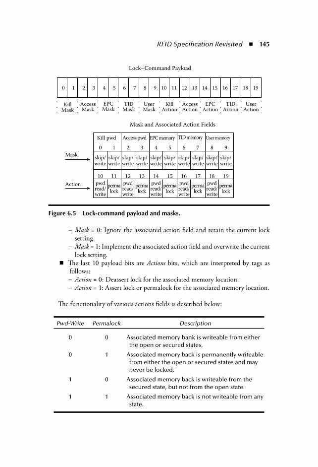
RFID Specification Revisited 145
Mask = 0: Ignore the associated action field and retain the current locksetting.Mask = 1: Implement the associated action field and overwrite the currentlock setting.
The last 10 payload bits are Actions bits, which are interpreted by tags asfollows:
Action = 0: Deassert lock for the associated memory location.Action = 1: Assert lock or permalock for the associated memory location.
The functionality of various actions fields is described below:
Pwd-Write Permalock Description
0 0 Associated memory bank is writeable from either the open or secured states.
0 1 Associated memory back is permanently writeable from either the open or secured states and may never be locked.
1 0 Associated memory back is writeable from the secured state, but not from the open state.
1 1 Associated memory back is not writeable from any state.
−
−
−−
Lock–Command Payload
Mask and Associated Action Fields
Mask
Action
0 1 2 3 4 5 6 7 8 9 10 11 12 13 14 15 16 17 18 19
KillMask
AccessMask
EPCMask
TIDMask
UserMask
KillAction
AccessAction
EPCAction
TIDAction
UserAction
.
.
.
.
.
.
.
.
.
.
.
.
.
.
.
.
.
.
.
.
.
.
.
.
.
.
.
.
.
.
.
.
.
Kill pwd Access pwd EPC memory TID memory User memory
0 1 2 3 4 5 6 7 8 9
10 11 12 13 14 15 16 17 18 19
skip/write
pwdread/write
permalock
pwdread/write
permalock
pwdread/write
permalock
pwdread/write
permalock
pwdread/write
permalock
skip/write
skip/write
skip/write
skip/write
skip/write
skip/write
skip/write
skip/write
skip/write
Figure 6.5 Lock-command payload and masks.
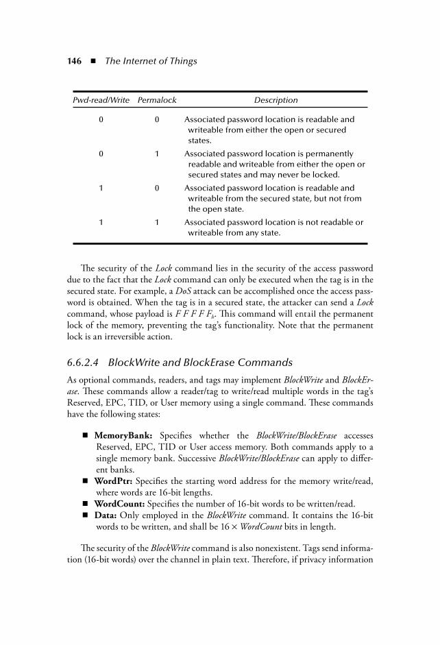
146 The Internet of Things
Pwd-read/Write Permalock Description
0 0 Associated password location is readable and writeable from either the open or secured states.
0 1 Associated password location is permanently readable and writeable from either the open or secured states and may never be locked.
1 0 Associated password location is readable and writeable from the secured state, but not from the open state.
1 1 Associated password location is not readable or writeable from any state.
The security of the Lock command lies in the security of the access passworddue to the fact that the Lock command can only be executed when the tag is in thesecured state. For example, a DoS attack can be accomplished once the access pass-word is obtained. When the tag is in a secured state, the attacker can send a Lockcommand, whose payload is F F F F Fh. This command will entail the permanentlock of the memory, preventing the tag’s functionality. Note that the permanentlock is an irreversible action.
6.6.2.4 BlockWrite and BlockErase Commands
As optional commands, readers, and tags may implement BlockWrite and BlockEr-ase. These commands allow a reader/tag to write/read multiple words in the tag’sReserved, EPC, TID, or User memory using a single command. These commandshave the following states:
MemoryBank: Specifies whether the BlockWrite/BlockErase accessesReserved, EPC, TID or User access memory. Both commands apply to asingle memory bank. Successive BlockWrite/BlockErase can apply to differ-ent banks.WordPtr: Specifies the starting word address for the memory write/read,where words are 16-bit lengths.WordCount: Specifies the number of 16-bit words to be written/read.Data: Only employed in the BlockWrite command. It contains the 16-bitwords to be written, and shall be 16 WordCount bits in length.
The security of the BlockWrite command is also nonexistent. Tags send informa-tion (16-bit words) over the channel in plain text. Therefore, if privacy information
RFID Specification Revisited 147
passes on the channel, it may be captured by a passive attacker listening to thechannel. Similarly, an active attacker can easily modify messages.
The BlockErase command is not encrypted upon transmission over the channel.As the information is transmitted in clear, an attacker may be able to easily modifythe messages. For example, an attacker can send the following message: 0xc8 -01- EPC - 0x00h - 0x8 - handle. Once the tag receives the previous message, the EPCmemory will be erased, leaving a nonoperative tag.
If the access password is equal to zero, the BlockWrite and BlockErase commandcan be accomplished from open state. So, under this situation, an adversary mayacquire or erase a tag’s data without a previous authentication. It is recommendedthat these two commands are deactivated when access password is fixed to zero.In fact, a more secure option would be to limit the usage of these two commands,independently of whether a tag is in a secured or open state, only when nonsensitiveinformation is in gear.
6.7 EPC Class-1 Generation-2+
The vast majority of work on the designing of security protocols for RFID eitherdo not conform to the EPC-C1G2 specification or suffer from serious securityflaws. In this section, some recent works are presented that try to raise the secu-rity level of low-cost RFID tags and ones that were developed “conforming” toEPC-C1G2.
6.7.1 Strengthening EPC TagsJuels [41] claims that EPC tags that do not have any explicit authentication func-tionality are vulnerable to cloning attacks. Tags emit their EPC in a promiscuousmode and readers accept the validity of the EPC at face value. The result is thattags compliant with EPC-C1G2 are vulnerable to elementary cloning attacks. Juelsintroduces the concept of skimming, which is the process of scanning a tag byobtaining its EPC for the purpose of cloning.
Several algorithms are proposed, distinguishing between two types of tags. Abasic tag is one that carries only the mandatory features of the EPC-C1G2 speci-fication. An enhanced EPC tag additionally includes the optional access-controlfunction.
Following is a description of the BasicTagAuth and the EnhancedTagAuth proto-cols. In a system with N tags, the integer i (with 1 i N) denotes the unique indexof an EPC tag. Ti and Ki denote the EPC identifier and the valid kill PIN of tag i,respectively. PIN-test(K) denotes an EPC tag command that causes a tag to outputa bit-response b: 0 if the kill PIN is correct, but outputs 1 otherwise.
148 The Internet of Things
6.7.1.1 Basic TagAuth Protocol
T: T TiT R: TR: if T = Tx for some 1 ≤ x ≤ N the i x else output “unknown tag” and halt
R: (j, {Pi(1), Pi(2), ,Pi(q)}) GeneratePINSet(i)[q] M valid for n = 1 to q doR T: PIN-test(Pi(n))T R: b if b = = 1 and n ≠ j then M invalid if b = = 0 and n = j then M invalidR: output M;
The key idea of this protocol is the presentation of spurious PINs as a meansof testing their authenticity. The q value is a security parameter that specifies thenumber of spurious PINs to be generated.
An attacker that performs skimming attacks can only create a cloned devicethat attempts to guess the correct PIN-trial j uniformly at random. The prob-ability of a successful attack (the cloned tag appearing to be valid) is clearly just1/q. However, the protocol is very inefficient (time-consuming) as large numberof messages (q) are exchanged between tags and readers to provide an accuratesecurity level.
6.7.1.2 Enhanced TagAuth Protocol
T: T TiT R: TR: if T = Tx for some 1 ≤ x ≤ N the i x, A Ai else output “unknown tag” and halt
R T: AT: if A = Ai then K Ki else K
T R: KT: if K = Ki then output “valid” else output “invalid”
Enhanced EPC tags have both access and kill PINs. Juels proposes a mutualauthentication protocol in which the access PIN (Ai) serves to authenticate thereader and the kill PIN (Ki) in turn serves to authenticate the tag.
Both of Juels’ proposals prevent a cloned tag from impersonating legitimate EPC-C1G2 tags. Although this problem constitutes a very interesting issue, the presentedproposals are only resistant to skimming attacks, being vulnerable to nearly all oth-ers: eavesdropping, active attacks, physical attacks, etc. Furthermore, we believe that

RFID Specification Revisited 149
focusing only on cloning and forgetting other important problems, such as privacy,tracking, denial of service, etc., should not be the correct approach.
6.7.2 Shoehorning Security into the EPC StandardJuels and Bailey [42] examine various ways that RFID tags might perform cryp-tographic functionality while remaining compliant with the EPC-C1G2 standard.Their key idea resides in taking an expansive view of EPC tag memory. Instead ofconsidering this memory merely as a form of storage, they use it as an input/outputmedium for interfacing with a cryptographic module within the tag. Therefore,read/write commands may carry out cryptographic values associated, such as mes-sages in a challenge-response protocol.
Juels and Bailey claim that EPC-C1G2 is a very limited protocol for entityauthentication. However, tags are not authenticated in the specification, whichfacilites counterfeiting. As an example, this simple challenge-response protocol issuggested:
R T: CR
T R: EPC, RT
RT = H(KTS,CR), and H() is a cryptographic primitive like a block-cipher,KTS is some secret key known only to the tag and the reader, and CR is a uniquechallenge.
To implement the previous protocol, commands designed for other purposeswill have to be reused or one should define custom or new commands. The task ofdefining the use of one protocol to carry the data units of another is often designedas protocol convergence. Concisely, the ISO 7816 command set to accomplishentity authentication of the tag is proposed.
Juels and Bailey’s work signals the need for mutual authentication between tagsand readers. However, the proposal is based on the assumption that EPC-C1G2tags might support onboard cryptographic modules. This is probably not realistic,at least at the present time. Moreover, this proposal is focused on tag authentication(counterfeiting). However, there are a great number of other security concerns thatshould be considered before proposing a protocol convergence. Otherwise, Juels’and Bailey’s proposal can be a good starting point.
6.7.3 Enhancing Security of EPC-C1G2Duc et al. [43] propose a tag-to-backend server authentication protocol. Duringmanufacturing, EPC and a tag’s access PIN are assigned. Then, it chooses a randomseed and store K1 = f(seed) in the tag’s memory and the corresponding backend
150 The Internet of Things
server’s database entry. The authentication protocols is described as follows, wheref() denotes a PRNG function.
R T: Query request
T: Compute M1 = CRC(EPC||r) Ki and C = CRC(M1r), where r is a nonce.
T R S: M1, C and r
S: From each tuple (EPC,Ki) in its database, theserver verifies whether the equation M1 Ki =CRC(EPC||r) and C = CRC(M1 r) hold. If a matchis found, then the tag is successfullyidentified and authenticated, and the serverwill forward a tag’s information to the readerand proceed to the next step; otherwise theprocess is stopped.
S R T M2
If R desires to perform read/write operation toa tag’s memory, it requests an authenticationtoken to M2 from S where M2= CRC(EPC||PIN||r)Ki. Then, R sends M2 to T. The tag receives M2and computes its M2, using its local values (PIN,r, EPC, Ki), and verifies whether the received M2equals the local one. If so, the tag will acceptthe end session command in the next step.
S R T: EndSession command
Upon receiving this command, both server and tagupdate their shared keys as Ki+1 = f(Ki).
The security of Duc et al.’s protocol greatly depends on key synchronizationbetween tags and backend server. The last message of the protocol is comprised ofan EndSession command, which is sent to both tags and readers. An interceptionof one of these messages will cause a synchronization loss between the tag and theserver. Therefore, the tag and the server cannot authenticate each other any more.Additionally, this fault may be exploited as follows: The EndSession message toserver may be intercepted avoiding its key updating and then a counterfeiting tagcan replay old data (M1, r, C) leading to its correct authentication.
Furthermore, the forward secrecy is not guaranteed. Forward secrecy is theproperty that guarantees that the security of the messages sent today will be validtomorrow. If the tag is compromised, obtaining (EPC, PIN, Ki), an attacker canverify whether past communications came from the same tag. This attack is basedin the symmetry of messages M1 and M2. Imagine that an attacker has stored old (M1,M2, r) messages. Now, he computes M1 M2 = CRC(EPC r) CRC(EPC||PIN||r),and using the compromised values (EPC, PIN, Ki) and the eavesdropped r, he couldverify that these messages came from the same tag.

RFID Specification Revisited 151
6.7.4 Mutual Authentication ProtocolChien and Chen [44] proposed a mutual authentication protocol in order to solvethe security weakness of Duc et al.’s proposal. The scheme consists of two phases:initialization and authentication.
6.7.4.1 Initialization Phase
For each tag denoted as Ti, the server randomly selects an initial authentication keyKi0
and an initial access key Px0. These two values joined with the EPC (EPCi), are
stored in the tag. The authentication key and the access key will be updated aftereach successful authentication. For each tag, the server maintains a record of sixvalues in its database: (1) EPCi; (2) the old authentication key for this tag (Kold), andis initially set to Ki0
; (3) Pold denotes the old access key for this tag, and is initially setto Pi0
; (4) Knew denotes the new authentication key, and is initially set to Ki0; (5) Pnew
denotes the new authentication key, and is initially set to Pi0; and (6) Data denotes
all the information about the tagged object.
6.7.4.2 The (n+1) Authentication Phase
R Ti: N1
The reader sends a random nonce N1 as a challengeto the tag.
Ti R S: M1, N1, N2
The tag generates a random number N2, computes M1= CRC(EPCi||N1||N2) Kin, and sends the valueback to the reader, which will forward thesevalues to the server.
The server interactively picks up an entry (EPCi,Kold, Knew, Pold, Pnew, Data) from its database,computes Iold = M1 Kold and Inew = M1 Knew; andchecks whether any of two equations Iold =CRC(EPCi||N1||N2)and Inew = CRC(EPCi||N1||N2) hold.The process is repeated until a match is found,meaning a successfully authentication of the tag.If a match is not found, a failure message issent to the reader and the process is stopped.
S R: M2, Data
After a successful authentication, the servercomputes M2 = CRC(EPCi||N2) Pold, or M2 =CRC(EPCi||N2) Pnew, depending on which value(Kold, Knew) satisfies the verification equation inthe previous step. It also updates Kold, = Knew,Pold, = Pnew, Knew = PRNG(Knew), and Pnew = PRNG(Pnew).The server sends M2, Data to the reader.
152 The Internet of Things
R Ti: M2
Upon receiving M2, the tag verifies whether theequation M2 Pin = CRC(EPCi||N2) holds. If so, itupdates its keys as Kin+1 = PRNG(Kin) and Pin+1 =PRNG(Pin).
Chien and Chen claim that the two sets of authentication keys and access keysprovide a defense against DoS attacks that may cause desynchronization between thetag and the reader. However, a malicious reader can easily accomplish an attack caus-ing loss of synchronization. The attacker sends a nonce N1 to the objective tag. The tagbackscatters M1 and N2. Now, the attacker has to generate M2. According to EPC-C1G2 specification, tags support onboard a 16-bit CRC, so the message M2 is a 16-bitlength. Although the attacker does not know any tag’s secret information, an exhaustivesearch can be carried out. A tag compliant with EPC-C1G2 standard has to providenearly 500 answers/sec (real conditions where noise may exist). Under these conditions,an exhaustive search of M2 takes approximately two minutes. So the attacker only hasto send all these messages to the tag, and one of those will lead to the update of the tag’skey. At this moment, the tag and the database can no longer be authenticated. There-fore, Chien and Chen’s protocol is not immune to denial-of-service attacks, either.
Moreover, Peris-Lopez et al. [45] have recently presented a deeper security anal-ysis of Chien and Chen’s protocol. From this analysis, it can be concluded thatnone of the authentication protocol objectives are met. Unequivocal identificationof tagged items is not guaranteed due to birthday attacks. Furthermore, an attackercan impersonate not only legitimate tags, but also the backend database. Locationprivacy is easily jeopardized by a straightforward tracking attack. Additionally, asuccessful auto-desynchronization (DOS attack) can be accomplished in the back-end database despite the security measures taken against it. Many of these resultsare a direct consequence of the linearity of cyclic redundancy codes (CRCs). Thedisaster of wired equivalent privacy (WEP) [46] and Secure SHell (SSH) [47,48]protocols are well-known examples of similar mistakes.
6.8 ConclusionsThis chapter has presented, in some detail, the EPCglobal Class-1 Generation-2specification. This specification may be considered as a “universal standard” forlow-cost RFID tags after its ratification by both EPCglobal and ISO.
First, the main concepts of the standard have been explained in order to introducethe reader to the subject. Second, a security analysis of all its commands (manda-tory and optional) has been accomplished. From this examination, we can concludethat the security level of EPC-C1G2 specification is very weak. Protection againstsecurity problems, such as privacy and tracking, is not guaranteed. Although tagspossess an onboard PRNG, it is mainly used to establish an identifier session, not

RFID Specification Revisited 153
for security reasons. In order to increase the security level and avoid the multistepprocedures, we recommend that tags support an onboard 32-bit PRNG.
Finally, some recent works that try to raise the security level of low-cost RFIDtags “conforming” to the EPC-C1G2 have been presented. However, these proto-cols have important security pitfalls, as it has been shown. Some of the proposalsask the CRC checksums for properties only found on standard hash-functions,something which is not realistic and generates the possibility of many attacks. Italso leaves open the issue of designing efficient, lightweight hash functions. Anotherrelated open issue is the designing of ciphers suitable to these constrained environ-ments. These protocols are based on several keys shared between the tag and readers(database). Improvements to key management are another thought-provoking issuethat should be considered by researchers.
To conclude, we expect that in the future EPC Generation-3 standard, a highersecurity level will be guaranteed. In this work, we have provided many ideas andinsights to help in solving the security pitfalls of its predecessor.
References [1] “Frequently asked questions”. http://www.rfidjournal.com, 2006. [2] C.M. Roberts. Radio frequency identification (RFID). Computers and Security,
25(1):18–26, 2006. [3] M. Rieback, B. Crispo, and A. Tanenbaum. The evolution of rfid security. IEEE
Pervasive Computing, 5(1):62–69, 2006. [4] RFID Consultation Website. http://www.rfidconsultation.eu/. May 15, 2006. [5] P. Peris-Lopez, J. Cesar Hernandez-Castro, J. Estevez-Tapiador, and A. Ribagorda.
RFID systems: A survey on security threats and proposed solutions. In Proc. of PWC06, vol. 4217 of Lecture Notes in Computer Science, Springer-Verlag,Heildeberg, Germany, pp. 159–170, 2006.
[6] EPCglobal. http://www.epcglobalinc.org/. February 5, 2006. [7] ISO — International Organization for Standardization. http://www.iso.org/. Feb-
ruary 15, 2006. [8] Class-1 Generation-2 UHF air interface protocol standard, version 1.0.9: “Gen-2.”
http://www.epcglobalinc.org/, January 2005. [9] EPCglobal Class-1 Gen-2 RFID Specification. Alien Technology, Morgan Hill,
CA, whitepaper, 2006. [10] M. Weiser. The computer for the 21st century. Scientific American, 265(3):94–104,
September 1991. [11] S. Weis, S. Sarma, R. Rivest, and D. Engels. Security and privacy aspects of low-cost
radio frequency identification systems. In Proc. of SPC’03, vol. 2802 of Lecture Notesin Computer Science, Springer-Verlag, Heildeberg, Germany, pp. 454–469, 2003.
[12] D. Ranasinghe, D. Engels, and P. Cole. Low-cost RFID systems: Confrontingsecurity and privacy. In Auto-ID Labs Research Workshop, Zurich, Switzerland,September, 2004.
[13] M. Feldhofer and C. Rechberger. A case against currently used hash functions inRFID protocols. In Proc. of RFIDSec’06, Graz, Austria, July 2006.

154 The Internet of Things
[14] K. Yksel, J.P. Kaps, and B. Sunar. Universal hash functions for emerging ultra-low-power networks. In Proc. of CNDS’04, San Diego, CA, January 2004.
[15] Amphion: CS5265/75 AES Simplex encryption/decryption. http://www.amphion.com, March 10, 2005.
[16] M. Feldhofer, K. Lemke, E. Oswald, F. Standaert, T. Wollinger, and J. Wolker-storfer. State of the art in hardware architectures. In Technical Report, ECRYPT Network of Excellence in Cryptology, 2005.
[17] M. Feldhofer, J. Wolkerstorfer, and V. Rijmen. AES implementation on a grain ofsand. In Proc. of IEEE on Information Security, IEEE Computer Society, vol. 152,pp. 13–20, 2005.
[18] T. Good, W. Chelton, and M. Benaissa. “Review of stream cipher candidates froma low resource hardware perspective.” http://www.ecrypt.eu.org/stream/hw.html,March 2006.
[19] M. Hell, T. Johansson, and W. Meier. “Grain: A stream cipher for constrainedenvironments and Grain-128.” http://www.ecrypt.eu.org/stream/, September 10,2006.
[20] C. de Canniere and B. Preneel. “Trivium specifications.” http://www.ecrypt.eu.org/ stream/, October 10, 2006.
[21] O. Kucuk. “Slide resynchronization attack on the initialization of Grain 1.0.”http://www.ecrypt.eu.org/ stream/, October 15, 2006.
[22] H. Gilbert, C. Berbain, and A. Maximov. “Cryptanalysis of grain.” http://www.ecrypt.eu.org/ stream/, September 20, 2006.
[23] M. Hell, T. Johansson, and W. Meier. Grain—a stream cipher for constrainedenviroments. In Proc. of RFIDSec’05, 2005, Graz, Austria, July, 2005.
[24] S.A. Weis, S.E. Sarma, R.L. Rivest, and D.W. Engels. Security and privacy aspectsof low-cost radio frequency identification systems. In Proc. of Security in Perva-sive Comp., vol. 2802 of Lecture Notes in Computer Science, Springer-Verlag,Heildeberg, Germany, pp. 201–212, 2004.
[25] D. Molnar and D. Wagner. Privacy and security in library RFID: issues, practices,and architectures. In Proc. of ACM CCS’04, pp. 210–219. ACM, ACM Press, NewYork, October 2004.
[26] C. Chatmon, T. Van Le, and M. Burmester. Secure anonymous RFID authentica-tion protocols. In Technical Report TR-060112, 2006.
[27] T. Dimitriou. A lightweight RFID protocol to protect against traceability andcloning attacks. In Proc. of PerCom’06, Pisa, Italy, 2006.
[28] S. Lee, T. Asano, and K. Kim. RFID mutual authentication scheme based on syn-chronized secret information. In Proc of Symposium on Applied Cryptography and Information Security, Glasgow, Scotland 2006.
[29] K. Rhee, J. Kwak, S. Kim, and D. Won. Challenge-response based RFID authenti-cation protocol for distributed database environment. In Proc. of SPC’05, vol. 3450of Lecture Notes in Computer Science, Springer-Verlag, Heildeberg, Germany,pp. 70–84, 2005.

RFID Specification Revisited 155
[30] G. Tsudik. YA-TRAP: Yet another trivial RFID authentication protocol. In Proc. of PerCom’06, Pisa, Italy, 2006.
[31] S.E. Sarma, S.A. Weis, and D.W. Engels. RFID systems and security and privacyimplications. In Proc. of CHES’02, vol. 2523 of Lecture Notes in Computer Sci-ence, Springer-Verlag, Heildeberg, Germany, pp. 454–470, 2002.
[32] E.Y. Choi, S.M. Lee, and D.H. Lee. Efficient RFID authentication protocol for ubiq-uitous computing environment. In Proc. of SECUBIQ’05, vol. 3823 of Lecture Notesin Computer Science, Springer-Verlag, Heildeberg, Germany, pp. 945–954, 2005.
[33] D. Henrici and P. Müller. Hash-based enhancement of location privacy for radio-frequency identification devices using varying identifiers. In Proc. of PERSEC’04,pp. 149–153. IEEE Computer Society, Washington, D.C., 2004.
[34] S.M. Lee, Y.J. Hwang, D.H. Lee, and J.I.L. Lim. Efficient authentication for low-cost RFID systems. In Proc. of ICCSA’05, vol. 3480 of Lecture Notes in ComputerScience, Springer-Verlag, Heildeberg, Germany, pp. 619–627, 2005.
[35] M. Ohkubo, K. Suzuki, and S. Kinoshita. Cryptographic approach to “privacy-friendly” tags. In Proc. of RFID Privacy Workshop, 2003.
[36] J. Yang, J. Park, H. Lee, K. Ren, and K. Kim. Mutual authentication protocol forlow-cost RFID. In Proc RFIDSec’05, 2005.
[37] A. Juels. Minimalist cryptography for low-cost RFID tags. In Proc. of SCN’04,vol. 3352 of Lecture Notes in Computer Science, Springer-Verlag, Heildeberg, Ger-many, pp. 149–164, 2004.
[38] I. Vajda and L. Buttyán. Lightweight authentication protocols for low-cost RFIDtags. In Proc. of UBICOMP’03, Atlanta, GA. 2003.
[39] P. Peris-Lopez, J.C. Hernandez-Castro, J. Estevez-Tapiador, and A. Ribagorda.M2AP: A minimalist mutual-authentication protocol for low-cost RFID tags. InProc. of UIC’06, vol. 4159 of Lecture Notes in Computer Science, Springer-Verlag,Heildeberg, Germany, pp. 912–923, 2006.
[40] P. Peris-Lopez, J.C. Hernandez-Castro, Juan M. Estevez-Tapiador, and A. Ribago-rda. EMAP: An efficient mutual authentication protocol for low-cost RFID tags.In Proc. of IS’06, vol. 4277 of Lecture Notes in Computer Science, Springer-Verlag,Heildeberg, Germany, pp. 352–361, 2006.
[41] A. Juels. Strengthening EPC tags against cloning. March 2005. [42] A. Juels and D. Bailey. Shoehorning security into the EPC standard In Proc. of
SCN’06, vol. 4116 of Lecture Notes in Computer Science, Springer-Verlag,Heildeberg, Germany, pp. 303–320, 2006.
[43] D.N. Duc, J. Park, H. Lee, and K. Kim. Enhancing security of EPCglobal Gen-2RFID tag against traceability and cloning. In Proc. of Symposium on Cryptography and Information Security, January, 2006.
[44] H.Y Chien and C.H Chen. Mutual authentication protocol for RFID conform-ing to EPC Class-1 Generation-2 standards. Computer Standards and Interfaces,29(2):254–259, 2007.
[45] P. Peris-Lopez, J.C. Hernandez-Castro, J. Estevez-Tapiador, and A. Ribagorda.Cryptanalysis of a novel authentication protocol conforming to EPC-C1G2 stan-dards. In Proc. of RFIDSec’07, Malaga; Spain, July 2007.

156 The Internet of Things
[46] N. Borisov, I. Goldberg, and D. Wagner. Intercepting mobile communications:the insecurity of 802.11. In Proc. of MobiCom’01, ACM, ACM Press, New York,pp. 180–189, 2001.
[47] A. Futoransky, and E. Kargieman. An attack on CRC-32 integrity checks ofencrypted channels using CBC and CFB modes. http://www.coresecurity.com/files/attachments/CRC32.pdf, 1999.
[48] N. Provos, and P. Honeyman. ScanSSH—Scanning the Internet for SSH servers.In Proc. of USENIX’01, San Diego, CA, December 2001.
157
Chapter 7
RFIG: Geometric Context of Wireless Tags
Ramesh Raskar, Paul Beardsley, Paul Dietz, and Jeroen van Baar
Radio frequency tags allow objects to become self-describing, communicating their identity to a close–at-hand radio frequency (RF) reader. Our goal is to build a Radio Frequency Identification and Geometry (RFIG) transponder. In addition to identity, a RFIG tag can record and respond its own geometric context, such as absolute and relative location with respect to adjacent RFIG tags.
7.1 Geometric Context of Wireless TagsThe geometry-rich functionality is achieved by augmenting each tag (Figure 7.1) with a photosensor (Figure 7.2). Optical communication with this composite RF-photosensing tag is achieved using modulated light. In this chapter, the
Contents7.1 Geometric Context of Wireless Tags........................................................157
7.1.1 How It Works ............................................................................... 1597.1.2 Applications..................................................................................159
Discussion.........................................................................................................163References .........................................................................................................164

158 The Internet of Things
operations are shown using a projector that is paired with the tag RF reader. The projector performs the dual operation of sending optical data to the tag (similar to a television’s infrared (IR) remote control unit) and also giving visual feedback by projecting instructions onto objects. Current tag readers operate in broadcast mode with no concept of a directional communication; however, the RFIG tags allow the locating of tags within a few millimeters, support selection of individual tags, and create a two dimensional (2D) or three dimensional (3D) coordinate frame for the tags. The system of projector and photosensing tags offer a set of rich, geometric operations. It presents a new medium for many of the results from the area of com-puter vision, with projector and tags replacing camera and image interest points (Raskar, Beardsley et al., 2004; Raskar, Nii et al., 2007).
The experimental work in this chapter is based on active, battery-powered RF tags. However, our goal has been to develop methods that can be used with pas-sive, nonpowered Radio Frequency IDentification (RFID) tags. The key issue in evolving this active tag system to passive tags would be “power.” In our work, we only allowed computation and sensing consistent with the size and power levels we felt were achievable on a passive RFID system. For example: (1) tags are not photosensing or computing until woken by the RF reader and (2) there isn’t a light-emitting diode (LED) on the tag as a visual beacon to a human or camera-based system because it would be power-hungry.
Conventional PFID
RF Data
Computer
READER
MicroController
Memory
Figure 7.1 Conventional Radio Frequency Identifaction (RFID) transponder communicates with RF reader and responds with the id number stored in the tag’s memory.
PhotosensorLight
RF Data
ProjectorComputer
READER
MicroController
Memory
Figure 7.2 The RFIG tag: Radio frequency identity and geometry (RFIG) tran-sponder communicates with RF reader as well as spatiotemporal light modulator, such as a modulated infrared (IR) light. For example, with a full-fledged data projector, one can find the stored id as well as the (x,y) projector pixel location that illuminates the tag.

RFIG: Geometric Context of Wireless Tags 159
Location tracking using RF-received signal strength or time of arrival is popu-lar, but requires multiple readers, and the accuracy may be insufficient for complex geometric procedures (Hightower and Borriello, 2001). Previous systems also have married RF tags with optical or ultrasound sensors to improve accuracy. Some systems use active RF tags that respond to laser pointers. The FindIT Flashlight project uses a one-way interaction and an indicator light on the tag to signal that the desired object has been found (Ma and Paradiso, 2002). Other systems use a two-way interaction where the tag responds back to the personal digital assis-tant (PDA) using a power-hungry protocol, such as the 802.11 or X10 (Patel and Abowd, 2003; Ringwald 2002). Cooltown (Hewlett Packard®) (The Cooltown Project, 2001) uses beacons that actively transmit device references, but without the ability to point and without visual feedback. The Cricket project (Teller et al., 2003) recovers PoseAware of a handheld device using installed RF and ultrasound beacons as well as doing recovers position and orientation of a handheld device.
7.1.1 How It WorksConventional tag communication works by broadcast from a RF reader, with response from all in-range tags. Limiting the communication to a required tag is traditionally achieved using a short-range tag reader and close physical placement with respect to the tag. In contrast, we can select tags for interaction from a longer-range using projected light, while ignoring unwanted in-range tags. The handheld device first transmits a RF broadcast. Each in-range tag is woken by the signal, and its photosensor takes a reading of ambient light, which is to be used as a zero for subsequent illumination measurements. The projector illumination is turned on. Each tag that detects an increase in illumination sends a response to indicate that it is in the beam of the projector and is ready for interaction.
The handheld device is aimed casually in the direction of a tagged surface, and then sends a RF signal to synchronize the tags, followed by illumination with a sequence of binary patterns, i.e., binary structured light. Each projector pixel emits a unique temporal Gray code and, thus, encodes its position. The tag records the Gray code that is incident on its photosensor, and then makes a RF transmission of its identity, plus the recorded Gray code back to the RF reader. The projector uses the identity plus the recorded (x,y) location to project instructions, text, or images on the tagged object. It is then straightforward to create correctly positioned aug-mentation on the tagged surface.
7.1.2 ApplicationsSeveral aspects of RFIG have been described in our previous work (Raskar et al., 2004). The work was motivated in terms of the commercially important application
160 The Internet of Things
of inventory control. But, we believe that photosensing tags may have many inno-vative uses, and, in this chapter, our goal is to present the new ideas in the context of a few promising examples. Below is outlined a broad mode of deployment for geometric analysis. Note that these are speculative uses, not actual work done.
1. Location Feedback, e.g., warehouse management (Figure 7.3): Consider the task of locating boxes containing perishable items about to expire. Even with traditional RF tagging with expiry date information recorded in the indexed database, the employee would have to serially inspect boxes and mark the about-to-expire product boxes. Using RFIG tags, the handheld or fixed pro-jector first locates the queried tags and then illuminates them with symbols, such as X and OK, so that the employee has a visual feedback. Note that a second user can perform similar operations without RF collision with the first reader or the tags because the two projector beams do not overlap.
2. Obstruction Detection, e.g., object obstructing a railroad track (Figure 7.4): A common computer vision task with a camera includes detecting abnormal con-ditions by performing image processing. One example is detecting obstruction on railway tracks; for example, raising an alarm if a person or some suspicious material is on subway tracks. Processing images of videos from camera-based systems to detect such events is difficult because the ambient lighting conditions can change and several other activities can result in false positives. But, one can
Figure 7.3 Application 1, Warehouse Scenario: Employee locates items about to expire and gets visual feedback. A second user performs similar operations, with-out conflict in the interaction because the projector beams do not overlap.
RFIG: Geometric Context of Wireless Tags 161
Figure 7.4 Application 2, Detecting obstruction on railway tracks, such as per-son on tracks near a platform, disabled vehicle at a railroad intersection, or sus-picious material on tracks. Finding obstruction with a camera-based system is difficult. The idea is to sprinkle RFIG tags along the track and illuminate them with a fixed or steered beam of temporally modulated light (not necessarily a projector). Tags respond with status of reception of the modulated light. Lack of reception indicates an obstruction, which can be relayed to a central monitoring facility where a human observer can carefully observe the scene, possibly with a pan/tilt/zoom surveillance camera.
solve this vision problem by sprinkling RFIG tags along the track. These tags can be illuminated with a fixed or steered beam of temporally modulated light (not necessarily a projector), such as a 40 kHz infrared beam from a sparse array of light emitters. Then, the operation is similar to the “beam break” technique commonly used to detect intruders. But, a wireless tag-based system is ideally suited for applications, where running wires to both ends is impractical. Using retro-reflective markers and detecting a return beam is another common strat-egy to avoid wires, but sprinkling a large number of markers creates an author-ing nightmare. In the case of RFIG, the tags identification and location can be easily reported along with the status of reception of the modulated light. Lack of reception indicates obstruction, which can be relayed to a central monitoring facility where a human observer can carefully observe the scene possibly with a pan/tilt/zoom surveillance camera.
3. Ordered Placement and Orientation, e.g., books in a library (Figure 7.5): A common task in libraries, pharmacies, or for facility managers is maintaining a large number of objects in a predetermined order. For example, in a library, if books are RF tagged, it is easy to obtain a book list within the RF range. However, without location information, it is difficult to find out which books
162 The Internet of Things
are out of alphabetical order. In addition, without book orientation informa-tion, it is difficult to detect books that are placed with spines upside down. With RFIG and a handheld projector, the system lists the book title as well as location. Then, the system sorts books by title as well as by their 2D geometric location. A mismatch in the two sorted lists indicates that the corresponding book is placed in a wrong position. The system knows the current location for the books as well their ideal position. The projector display gives immediate visual feedback and instructions (shown in Figure 7.5 as arrows from current positions to intended positions). A single book also can be tagged with two RFIG transponders, one at the top of the book spine and one at the bottom. Then, comparing the coordinates of these two tags allows one to find out if the book has been placed upside down.
4. 3D Path Planning/Guiding, e.g., guiding a robot on an assembly line for arbitrarily oriented objects (Figure 7.6): RFIG tags can be used in factories for robot guidance. The idea is similar to other “laser-guided” operations. Suppose a robot is instructed to grab a certain object from a pile moving on a conveyor belt. RFID can simplify the object recognition problem in the machine’s vision, but precisely locating the object would be difficult. The idea is to use a fixed projector to first locate the RFIG-tagged object and then illuminate the object with a steady, easily identifiable temporal pat-tern. A camera attached to the robot arm locks onto this pattern by doing pattern matching and allows the robot to home in on the object.
Figure 7.5 Application 3, Books in a library. If books are RF tagged, it is easy to obtain a list of books within the RF range. However, without location information, it is difficult to find out which books are out of alphabetical order. In addition, without book orientation information, it is difficult to detect books whose spines are placed upside down. With RFIG and a handheld projector, the system finds a book title as well as location. Based on the mismatch in title sort with respect to the location sort, the system gives immediate visual feedback and instructions, shown as arrows for original positions.

RFIG: Geometric Context of Wireless Tags 163
Notice that in a majority of the applications described above, the projector behaves similar to devices that we are all familiar with, e.g., remote controls and laser pointers, but with some spatial or temporal modulation of light. The projector is a glorified remote control communicating with a photosensor in the location-sensing phase and a glorified laser pointer in the image projection phase.
DiscussionSeveral problems can influence optical communication between the projector and a tag. It can be affected by ambient light; however, wavelength division multiplexed communication is commonly used to solve this problem (e.g., TV remote and IR photosensor). The optical communication also gets noisier as projector–tag distance increases, and if the photosensor gets dirty. However, within these limitations, the RFIG method can support very intricate and multipurpose geometric operations with the ambient intelligence provided by wireless tags. The work indicates some of the possibilities for blurring the boundaries between the physical and digital worlds
Figure 7.6 Application 4, Laser-guided robots: To guide a robot to pick a certain object from a pile moving on a conveyor belt, the projector locates the RFIG-tagged object and illuminates it with an easily identifiable temporal pattern. A camera attached to the robot arm locks onto this pattern and allows the robot to home in on the object.
164 The Internet of Things
by making the everyday environment into a self-describing wireless data source, a display surface, and a medium for interaction.
ReferencesCooltown Project, The. 2001. http://www.cooltown.com/research/.Hightower, J. and Borriello, G. Location systems for ubiquitous computing. Computer,
34(8): 57–66, August 2001.Ma, H. and PARADISO, J. A. 2002. The FindIT flashlight: Responsive tagging based on
optically triggered microprocessor wakeup. Ubicomp 2002 International Conference,Goteborg, Sweden, Springer-Verlag, Heidelberg, Germany, pp 160–167.
Patel, S.N. and Abowd, G. D. 2003. A 2-way laser-assisted selection scheme for handhelds in a physical environment. Ubicomp International Conference 2003, Seattle, WA, October 2003, Springer-Verlag, Heidelberg, Germany, pp. 200–207.
Raskar, R., Beardsley, P.,Van Baar, J., Wang, Y., Dietz, P., Lee, J., Leigh, D. and Willwa-cher, T. 2004. RFIG lamps: Interacting with a self-describing world via photosensing wireless tags and projectors. ACM Trans. Graph. (SIGGRAPH) 22, 3: 809–818.
Raskar, R., Nii, H., deDecker, B., Hashimoto, Y., Summet, J., Moore, D., Zhao, Y., Westhues, J., Dietz, P., Barnwell, J., Nayar, S., Inami, M., Bekaert, P., Noland, M., Branzoi, V., and Bruns, E. 2007. Prakash: lighting aware motion capture using photosensing markers and multiplexed illuminators. ACM Trans. Graph. 26, 3 (Jul. 2007), 36. DOI=http://doi.acm.org/10.1145/1276377.1276422.
Ringwald, M. 2002. Spontaneousinteraction with everyday devices using a PDA workshop on supporting spontaneous interaction in ubiquitous computing settings. UbiComp 2002 International Conference, Goteborg, Sweden, Springer-Verlag, Heidelberg, Germany.
Teller, S., Chen, J., and Balakrishnan, H. 2003. Pervasive poseaware applications and infra-structure. IEEE Computer Graphics and Applications, July/August 2003, Canmore, Alberta, Canada.

165
Chapter 8
RFID Application in Animal Monitoring
Vasileios Ntafis, Charalampos Z. Patrikakis, Eirini G. Fragkiadaki, and Eftychia M. Xylouri-Fragkiadaki
Contents8.1 Introduction ............................................................................................166
8.1.1 Systems of Identification and Traceability.....................................1678.2 Specific Requirements for Use of RFID Technologies in Animals ...........168
8.2.1 Means of Identification.................................................................1688.2.2 Standards Regarding the Use of RFIDs: ISO 11784
and ISO 11785 and the Role of ICAR ...........................................1688.2.3 Evaluation of Current Electronic Means of Identification
with Emphasis on RFID................................................................1708.2.3.1 Ruminal Bolus................................................................1718.2.3.2 Electronic Ear Tags.........................................................1728.2.3.3 Injectable Capsules .........................................................1728.2.3.4 Tag Attachment..............................................................173
8.2.4 Comparison of the Electronic Means of Identification..................1738.3 Legislation............................................................................................... 1748.4 Systems Using Electronic Identification Devices and Electronic
Data Transfer...........................................................................................176

166 The Internet of Things
8.1 IntroductionUse of Radio Frequency IDentification (RFID) technology in animal tracking hasbeen a practise for the past number of years in countries around the world. RFIDtechnology is used to track domestic, wild, and farm animals, during which therehave been efforts to standardize the methods and the specific RFID tag technologyused. As examples of the above, a U.S. Department of Agriculture (USDA) projectis in effect for tracking captive deer and elk in the United States based on the useof RFID tags in order to determine how deer and elk contract chronic wastingdisease, a fatal neurological disorder. In the standardization field, the U.S. AnimalHealth Association has already adopted a draft U.S. Animal Identification Plandeveloped by a group of representatives from the cattle industry and state and fed-eral agencies overseeing the food supply. At the same time, AIM Global has devel-oped a draft standard for RFID in food animals to address growing concerns aboutthe threat of terrorist attacks and the recent outbreaks of both bovine spongiformencephalopathy (BSE: mad cow disease) and hoof-and-mouth disease in differentparts of the world.
As the use of RFID technology gets less expensive, more countries are adoptingthe use of animal tagging. As an example, the USDA has announced plans for theuniversal tagging of livestock in the United States with RFID by the year 2009.
Providing a brief but comprehensive coverage of the use of RFID technologiesin animal identification, tagging, and monitoring, this chapter presents the use ofRFID technology for supporting all animal-related RFID activities. A reference tothe current standardization and coverage of the use of RFID technology, as definedthrough global organizations and associations, will be provided as an introduc-tory section to these issues. Following this approach, the chapter will provide acomprehensive coverage of the use of RFID in relation to domestic, farm, and
8.4.1 Databases: Opening Up a New Prospect.......................................1778.4.1.1 Holding Animals Identification Parameters....................1788.4.1.2 Animal Movement Parameters........................................1788.4.1.3 Productive and Reproductive Data .................................1798.4.1.4 Animal Health Parameters Per Individual ......................179
8.5 Recorded Parameters in Domestic and Wildlife Animals ........................1808.5.1 Domestic Animals ........................................................................180
8.5.1.1 Farm Animals.................................................................1808.5.1.2 Companion Animals ......................................................181
8.5.2 Nondomestic Animals ..................................................................1818.5.2.1 Wild Animals .................................................................1818.5.2.2 Animals in Captivity ......................................................181
8.6 Open Issues .............................................................................................182References .........................................................................................................183

RFID Application in Animal Monitoring 167
wild animals, the particularities that this use has in each case, while, on the otherhand, providing example prototype uses for each case. Legislation issues, that areaddressed globally, will also be tackled, giving an overview of the existing legislativeframework for the use of RFID as regards to animals. Note that emphasis is placedonly on RFID technology as it is used for monitoring animal activities. Therefore,basic knowledge of the use and operation of RFID systems is required, even thoughthe chapter does not address technical issues of RFID.
8.1.1 Systems of Identification and TraceabilityThe necessity of systems of identification and traceability becomes more obviousday by day. The demands of quality control in agricultural animals, as well as tech-nology’s evolution, comprise these two factors that promote the ceaseless improve-ment of the identification systems. Only few countries worldwide have managedto establish such systems. National laws and regulations come constantly intoforce, laying new guidelines for these systems so as to improve their credibility.At the same time, technology has reached a point where the use of electronicmeans of identification (RFID) is possible, resulting in the increasing use of theapplication.
The outbreak of BSE, commonly known as mad cow disease, revealed thenecessity of systems of identification and traceability. During the last two decades,concerns about the safety and quality of food have increased at both governmen-tal and consumer levels. The importance of traceability of animals and animalproducts has grown as food production and marketing have been removed fromdirect consumer control. Worldwide trading increases the possibilities of a diseaseoutbreak, when at the same time it makes food traceability more difficult. Despitethese, only little progress has been achieved in the field of the systems mentionedabove (McKean, 2001; Saa et al., 2005).
In the European community, there are regulations for agricultural animal’straceability and movements. Thus, detection of animals during outbreaks is possi-ble. Moreover, in many cases, countries give subsidies depending on the number ofanimals in a herd and other requirements, to farms with cattle, sheep, and goats. Asthe determination of the number is difficult, there is always the possibility of fraud.Good identification systems can help minimize this fraud (Wismans, 1999).
Therefore, with the application of identification systems, animal diseases (some-times foreign for a country) can be controlled, surveyed, and prevented. Officialidentification of animals in national, intracommunity, and international commercealready takes place, while at the same time, identification of livestock that are vacci-nated or tested under official disease control or eradication is also possible. Last, butnot least, blood and tissue specimens can be accurately identified, and the healthstatus of herds, regions, and countries can be certified (National Center for AnimalHealth Programs, USDA Web site).
168 The Internet of Things
8.2 Specific Requirements for Use of RFID Technologies in Animals
8.2.1 Means of IdentificationThe identification of agricultural animals in the United States was taking place forthe first time at the end of the 19th and the beginning of the 20th century. Brand-ing with a hotiron was used by cattle ranchers to indicate possession and to hope-fully prevent cattle rustling. For keeping records, swine owners were employing earnotches. These two methods, however, stopped being popular due to their negativeeffects on production as well as for welfare reasons. Thus, the use of ear tags andtattoos appeared in the beginning of the 1960s (National Center for Animal healthPrograms, USDA Web site).
Dairy farmers have been keeping records for over 100 years. Each animal wasidentified and, in these records, was information mainly concerning reproduction per-formance. In 1950, there were several countries establishing identification systems aspart of hygiene programs that were being mandated. This led actually to the establish-ing of two different identification systems with many disadvantages for the farmers, asthis was less friendly, more expensive, and of lower quality (Wismans, 1999).
As it is obvious, many different means of identification have been used, suchas ear tags, ear notches, tattoos, branding, paint marks, and leg bands. Electronicmeans of identification, which is comprised of barcodes and RFID transmitters(ruminal boluses, injectable transponders, and electronic ear tags) seem to havebecome more popular now for the traceability of animals (agricultural, domestic,and wildlife). In the European community, cattle are identified by ear tags. In thefuture, ear tags and RFID tags will comprise the most important means used in theidentification and registration systems of agricultural animals.
8.2.2 Standards Regarding the Use of RFIDs: ISO 11784 and ISO 11785 and the Role of ICAR
As regards standardization concerning the use of RFID technology in animals,there are two international standards that apply: ISO (International Organizationof Standards)11784 and ISO 11785. ISO 11784 refers to the Code Structure, whileISO 11785 refers to the Technical Concept.
According to the ISO standard, the carrier frequency for animal identifica-tion is 134.2 kHz, while there are three protocols in use to communicate betweentag and reader. In regard to the bit stream used for communication between thetransponder (RFID tag) and the transceiver (Reader), this includes an identifica-tion code, together with a code to ensure correct reception of the bit stream. Thisidentification code is described in ISO 11784. On the other hand, use and handlingof the transmitted information (activation of transponder, information transfer,protocols used) are described in ISO 11785. Therefore, the combination of the two
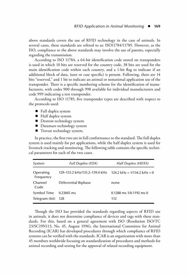
RFID Application in Animal Monitoring 169
above standards covers the use of RFID technology in the case of animals. Inseveral cases, these standards are refered to as: ISO11784/11785. However, as theISO, compliance to the above standards may involve the use of patents, especiallyregarding the transmission.
According to ISO 11784, a 64-bit identification code stored on transpondersis used in which 10 bits are reserved for the country code, 38 bits are used for themain identification code within each country, and a 1-bit flag to indicate if anadditional block of data, (user or case specific) is present. Following, there are 14bits “reserved,” and 1 bit to indicate an animal or nonanimal application use of thetransponder. There is a specific numbering scheme for the identification of manu-facturers, with codes 900 through 998 available for individual manufacturers andcode 999 indicating a test transponder.
According to ISO 11785, five transponder types are described with respect tothe protocols used:
Full duplex systemHalf duplex systemDestron technology systemDatamars technology systemTrovan technology system.
In practice, the first two are in full conformance to the standard. The full duplexsystem is used mainly for pet applications, while the half duplex system is used forlivestock tracking and monitoring. The following table contains the specific techni-cal parameters for each of the two cases.
Though the ISO has provided the standards regarding aspects of RFID usein animals, it does not determine compliance of devices and tags with these stan-dards. For this, based on a general agreement with ISO (Resolution ISO/TC23/SC19N113, No. 45, August 1996), the International Committee for AnimalRecording (ICAR) has developed procedures through which compliance of RFIDsystems can be verified with the standards. ICAR is an organization with more than45 members worldwide focusing on standardization of procedures and methods foranimal recording and testing for the approval of related recording equipment.
System Full Duplex (FDX) Half Duplex (HDXS)
OperatingFrequency
129–133.2 kHz/135.2–139.4 kHz 124.2 kHz 1/134.2 kHz 0
ChannelCode
Differential Biphase none
Symbol Time 0.23845 ms 0.1288 ms 1/0.1192 ms 0
Telegram (bit) 128 112

170 The Internet of Things
According to the ICAR-defined procedure for testing the compliance of RFIDtransponders with ISO standards, four types of ISO-compliant transponders foranimal use are covered:
Electronic ruminal bolus transponder Electronic ear tag transponders Injectable transponders Tag attachment
According to the test procedure, a manufacturer can apply for a full, limited, orlisting upgrade test when requesting ICAR certification.
8.2.3 Evaluation of Current Electronic Means of Identification with Emphasis on RFID
It is widely accepted that identification and registration systems are necessaryfor animal traceability. National financial aid for systems for cattle, sheep, andgoats demands reliable management, which depends on life-long identification ofindividual animals. Current methods are vastly in need of improvement, as theysuffer from certain drawbacks, such as tag loss, breakage or alteration, slow datarecording, and high error rates due to manual data transcription.
Passive electronic identification transponders consist of an electric resonance cir-cuit, acting as a receiving/transmitting antenna, connected to an electronic micro-chip. When such a transponder is placed in an electromagnetic field of sufficientfield strength, the induced voltage in the resonance circuit powers the microchip,which will turn on and start sending back its stored identification number via theresonance circuit. The reader, which generates the electromagnetic field, receivesthe transmitted code and displays it on a screen (Jansen and Eradus, 1999).
An electronic identifier device should remains on the animal for life and berecoverable after slaughter. In addition, it should be resistant to the hard farm con-ditions and provide information whenever needed. Finally, its cost should be lowenough to permit its application to all agricultural animals.
A four-year program of the European Commission’s Joint Research Center (Ispra,Italy) was implemented to encompass one million animals (cattle, sheep, and goats)and aimed at the evaluation of electronic means of identification. This IDEA program(Identification Electronic des Animaux) took place between 1998 and 2001 in sixcountries of the European community and revealed that improvement of identifica-tion and registration systems can be achieved via electronic means of identification.
In this program, three kinds of electronic means of identification were evalu-ated: electronic ear tags, ruminal boluses, and subcutaneous ear injectable capsules.Each of them contained an RFID transponder capable of transmitting the animal’sidentification code to a portable or static reader device.

RFID Application in Animal Monitoring 171
The final report verifies that electronic means of identification can improve iden-tification and registration systems. In addition, it points out that electronic ear tagscan be applied in cattle, sheep, and goats of all ages, though ruminal boluses can beapplied at a live weight of 25 kg for sheep and goats, and in cattle less than 20 daysold. Finally, electronic ear tags and ruminal boluses present the lowest mean percent-ages of losses or damages ( 0.5 percent) and, on average, their retention rates ( 99.5percent) are substantially higher than commonly observed retention rates for plasticear tags (Institute for the Protection and Security of the Citizen Web site).
8.2.3.1 Ruminal Bolus
The ruminal bolus is a ceramic capsule retained in the reticulum or the secondstomach of ruminants. It incorporates a radio frequency transponder capable ofautomatically communicating information to a reader. Ruminal boluses can beused as electronic means of ruminant identification.
There are different kinds of ruminal boluses available, for example, the ceramic,the monolithic, and the steel-weighted boluses. The ceramic boluses are cylindricalto enable oral administration in young animals. The ceramic material enclosingthe electronic transponder is nontoxic. Small steel metallic objects near the cap-sule appear not to affect the reading distance of these transponders (Hasker andBassingthwaite, 1996). The steel-weighted bolus was developed in The Netherlandsby Nedap Agri and consists of the transmitter enclosed in glass, which is thenenclosed in plastic. The steel-weight is positioned eccentrically.
Electronic passive devices incorporated in ruminal boluses have proven to bea safe choice for permanent ruminant identification (Caja et al., 1999). In the pastfew years, different kinds of boluses have been used in cattle, sheep, and goats with-out any negative effects on animals being reported. In spite of the size of the bolus,there doesn’t seem to be any negative effects on the food intake, the digestion, orthe morphology of the ruminal wall. However, there isn’t a unanimous agreementon this among the scientific community. Some scientists imply that the transpondermay alter, via mechanical action, the reticuloruminal mucosa and rumination pat-terns. Furthermore, the transponder may increase, via its electromagnetic action,the growth rate and metabolic activity of ruminal bacteria (Antonini et al., 2006).
At this point, it is appropriate to mention that foreign bodies can be introducedin the rumen without any negative effects on the ruminant’s physiology. Magnetsfor metal foreign body entrapment and trace element, and antibiotic and growthpromoter boluses are some examples.
In addition, in lactating ruminants, the development of their young animals’forestomachs can be helped by the existence of particles, as the forestomachs havenot been fully developed in the first months. The development is particularly stim-ulated by providing solid food progressively, along with milk (Beharka et al., 1998).Foreign bodies in the forestomachs, as well as solid food for lactating animals,stimulate their motility and the rumination.
172 The Internet of Things
In recent studies, it is reported that the recommended live weight for ruminalbolus administration (66 20 mm, 65 g) in cattle, sheep, and goats is 30 kg, 25 kgand 20 kg, respectively. The retention rates for the boluses were 99.7, 100, and98.8 percent, respectively. Caja et al. (1999) suggested that the use of the ceramicbolus is recommended as a safe and tamper-proof method for electronic identifica-tion of ruminants once the animals have reached a weight where successful admin-istration is possible.
Other researchers suggest that boluses can be administrated in sheep longbefore they reach 25 kg. Twenty kilogram boluses can be administered to lambsafter weaning at the fifth week, with weight of more than 12 kg. These kinds ofboluses do not affect the age at the end of fattening or the mortality rate, and theretention rate is 100 percent (Garin et al., 2003).
8.2.3.2 Electronic Ear Tags
Electronic RFID transponders are embedded in ear tags, and they work as remotelyactivated receiver–transmitters, which use a short-range radio frequency. The eartags are plastic-covered transponders capable of being fixed to the ear of an animalusing a locking mechanism or to be attached in such a manner that it cannot beremoved from the tag without damaging it.
The electronic transponders mounted in ear tags are an official, but not man-datory, option for identification of dairy cattle in North America and all cattle inthe European Union, although visual tags must support the electronic identifi-cation in the European Union and in Canada. Externally mounted transpondersare easily located and removed upon slaughter of the animal and are unlikely toenter the food chain. However, as any external tag is vulnerable to loss, removal,or damage, efforts to develop permanent electronic identification are focusing oninternal forms, such as injected transponders (Stanford et al., 2001).
8.2.3.3 Injectable Capsules
The injectable capsules are also electronic means of identification, with electronicRFID transponders being implanted in several places in the animal’s body. Thetransponders are covered by a capsule of biomedical glass, which is nontoxic forthe animal. The preferable locations are the forehead, the external ear lobule, theposterior auricular base, and in the intraperitoneal cavity. In cattle, the optimumsite of implantation is controversial. It has been proposed that the best site wasin the base of the ear tissue, under the scutiform triangular cartilage (Fallon andRogers, 1992; Fallon and Rogers, 1999). However, in a study on swine, the factorsof skin damage and migration were analyzed, as well as the reading efficiency, andit was found that the best implant area for an injectable implant was the posteriorear base (Silva and Naas, 2006). The results of a study in adult sheep suggested that

RFID Application in Animal Monitoring 173
first the armpit, and second the ear base, as suitable subcutaneous injection sites forelectronic identification (Caja et al., 1999).
The recovery of these electronic implants in abattoirs (slaughterhouses) is veryimportant for two reasons. First of all, the recovery can prevent more than one useof the injectable capsule. Second, the recovery prevents the capsules from remain-ing in the food products with the risk of being consumed (Sheridan, 1991).
Injectable transponders meet the requirements of an identification system thatis permanent, unique, tamper-proof, and does not produce apparent disturbancesto the animals at application, especially for newborn piglets. The transponders canbe applied shortly and easily after birth. The use of 23- to 34-mm transponders inthe intraperitoneal position seems to be preferable (Caja et al., 2005).
8.2.3.4 Tag Attachment
These are transponder components covered by a primary protection layer and meantfor producing one or more of the three transponder types mentioned above or othertypes of animal electronic transponders.
8.2.4 Comparison of the Electronic Means of IdentificationComparison of electronic and a simple means of identification has taken place inswine, suggesting that neither has any negative effect on animal health and per-formance. Farm losses averaged 1.6 percent for ear tags (visual, 0.8; half duplex,1.9; full duplex, 2.7 percent; P 0.05) and 1.8 percent for intraperitoneal-injectedtransponders (half duplex, 1.7; full duplex, 1.9 percent; P 0.05). Moreover,1.4 percent electronic failures occurred in the electronic ear tags (half duplex, 2.2;full duplex, 0.6 percent; P 0.05), but not in the intraperitoneal-injected tran-sponders. Visual ear tags and intraperitoneal-injected transponders were efficientlyretained under conditions of commercial pig farms, which agrees with the mini-mum values recommended by the International Committee for Animal Recording( 98 percent), but when readability and reading ease were also included as decisioncriteria, injectable transponders were preferred (Babot et al., 2006). In addition,among the electronic ear tags and injectable transponders, another experiment sug-gests the second, (intraperitoneal implanted) as the best identification system forpigs (Caja et al., 2005).
The major advantage of passive injectable transponders is their small size,allowing an early application in young and small animals. One of the major dis-advantages of the injectable capsules is the difficulty of recovery at slaughter; espe-cially when the site is in the base of the ear tissue under the scutiform triangularcartilage, the recovery can be unpredictable. Due to the risk of entering in thefood chain, there are researchers who consider the implantable transponders tobe impractical (Fallon et al., Web site). On the contrary, the ruminal boluses can

174 The Internet of Things
be easily recovered at slaughter by palpation of the reticulum, thus, possible con-tamination of food products with foreign bodies is avoided. However, the easiestelectronic means of identification to be recovered at slaughter remains the elec-tronic ear tag.
The Department of Environment, Food and Rural Affairs (DEFRA) publisheda preliminary study in 2003 on the cost of the implementation of the EuropeanRegulation No 21/2004 in the United Kingdom. This study concluded that theelectronic means of identification was less costly than the conventional means.However, there is some disagreement in this field, particularly in Spain. Accord-ing to Saa et al. (2005), the use of a mixed strategy combining conventional eartags (for animals intended for slaughter) and electronic boluses (for breeding stock)seemed to be the most affordable strategy.
One of the major advantages of the ruminal boluses compared to the electronicear tags and even to the injectable transponders is that they are more tamper proof.Their position makes it impossible for the bolus to be removed or replaced, whereasfor the other two, replacement is feasible. In addition, the retention rates for bolusesare higher than that of the electronic ear tags (Fallon et al., Web site).
8.3 LegislationWith the establishment of a single market in the European community, as wellas the existence of both intracommunity and international trade, there arose newneeds and demands for the improvement of the identification and registration sys-tems. As a result, the first European regulation for national systems came into forcein Directive 92/102/EEC, which made recording of animals and their movementsobligatory. Before 1992, identification and registration systems regulations con-cerned only purebred animals (Wismans, 1999). Many regulations and directiveshave been enforced since then, with legislation for European countries nowadaysbeing formed, as described below.
Regulation (EC) No 1760/2000 recently came into effect, which estab-lishes a system for the identification and registration of bovine animals aswell as the labeling of beef and beef products. The most important pointsof this regulation, which repealed Council Regulation (EC) No 820/97 are:The system for the identification and registration shall comprise the fol-lowing elements: ear tags, computerized databases, animal passports, andindividual registers kept on each holding. All animals on a holding born after 31 December 1997 or intended forintracommunity trade shall be identified by an ear tag approved by a com-petent authority, applied to each ear. Both ear tags shall bear the sameunique identification code, which makes it possible to identify each animalindividually together with the holding on which it was born.

RFID Application in Animal Monitoring 175
After 31 December 1999, ear tags shall be applied within a period not lon-ger than 20 days from the animal’s birth. No animal may be moved from aholding unless it is identified. Any animal imported from a third (nonEU) country shall be identified onthe holding of destination by an ear tag within a period not exceeding 20days, and in any event before leaving the holding. The competent authority of the Member States shall set up a computer data-base, which shall become fully operational no later than 31 December 1999. From 1 January 1998, the competent authority shall issue a passport foreach animal, within 14 days of the notification of its birth. Each keeper of animals shall maintain an up-to-date register; shall reportwithin a period of seven days all animal movements, births, and deaths;and shall complete the animal’s passports. The register shall be available atall times to the competent authority upon request. The Commission is examining, on the basis of work performed by the JointResearch Centre, the feasibility of using electronic means for the identifica-tion of animals.
Finally, in April of 2005, Commission Regulation (EC) No 644/2005 came intoforce, authorizing a special identification system for bovine animals kept for cul-tural and historical purposes on approved premises. According to this regulation:
When the animals are moved to the premises, the approved ear tags may beremoved from the animals without permission of the competent authority,but under his control. The animals shall be identified by one of the following means to be decided bythe competent authority: two plastic or metallic ear tags, one plastic or metal-lic ear tag together with a brand marking, a tattoo, or an electronic identifiercontained in a ruminal bolus or in the form of an injectable transponder.
Concerning ovine and caprine animals, Council Regulation No 21/2004came into force in December of 2003, establishing a system for the identificationand registration.
In 1998, the Commission launched a large-scale project on the electronic iden-tification of animals (IDEA) and its final report was completed on 30 April 2002.That project demonstrated that a substantial improvement in ovine and caprine ani-mal identification systems could be achieved by using electronic identifiers for theseanimals, provided that certain conditions concerning the accompanying measureswere fulfilled. The technology for the electronic identification of ovine and caprineanimals has been developed to the stage where it can be applied. Pending develop-ment of the implementing measures required for the proper introduction of thesystem of electronic identification communitywide, an efficient identification andregistration system, enabling future developments in the field of implementation of

176 The Internet of Things
electronic identification on a communitywide scale, should permit the individualidentification of animals and their holding of birth.
In accordance with the provisions of this regulation, each Member Stateshall establish a system for the identification and registration of ovine andcaprine animals. The system shall comprise the following elements: meansof identification to identify each animal, up-to-date registers kept on eachholding, movement documents, and a central register or a computer data-base. The Commission and the competent authority of the Member Stateshall have access to all information covered by this regulation. All animals on a holding born after 9 July 2005 shall be identified within aperiod to be determined by the Member State as from the birth of the animaland in any case before the animal leaves the holding on which it was born.The period shall not be longer than six months. For animals kept in extensiveor free-range farming sites, this may be extended to nine months. Animals shall be identified by a first means of identification: an ear tag. Theyshall be identified also by a second means of identification approved by the com-petent authority. The second means may consist in an ear tag, a tattoo (exceptfor animals involved in intracommunity trade), a mark on the pastern (part ofthe hoof) (solely in the case of caprine animals), or an electronic transponder. Each keeper of animals shall maintain an up-to-date register. From 1 January2008, and for each animal born after that date, the register must contain atleast the following information: (1) the identification code of the animal, (2)the year of birth and date of identification, (3) the month and the year of deathof the animal on the holding, and (4) the race and, if known, the genotype. From 9 July 2005, whenever an animal is moved within the national ter-ritory between two separate holdings, it shall be accompanied by a move-ment document. From 1 January 2008, electronic identification shall be obligatory for allanimals. However, Member States in which the total number of ovine andcaprine animals is 600,000 or less may make such electronic identificationoptional for animals not involved in intracommunity trade. From 9 July 2005, the competent authority of each Member State shall setup a computer database. From 1 January 2008, the database, with informa-tion for each separate movement of animals, shall be obligatory.
8.4 Systems Using Electronic Identification Devices and Electronic Data Transfer
During the past few years, different systems using electronic identification devicesand electronic data transfer have been evaluated around the world. Nationalauthorities in many countries have commissioned pilot trials to evaluate the

RFID Application in Animal Monitoring 177
technology surrounding electronic means of identification and its systems, andwhere they can be applied.
The USDA has commissioned pilot projects and field trials concerning theNational Animal Identification System (NAIS). These projects have very signifi-cant results with regards to NAIS implementation, since the projects supportthe findings that the electronic systems of identification and traceability can beimplemented in real life. During 2004, 16 pilot projects took place in differentStates where low-frequency (LF) RFID technology was used. In one of these proj-ects, the Florida Pilot Project specifically, (LF) RFID tags were used as a meansof identification in 17,000 calves, 6,500 cull cows (adult cows with one or morecalves and which are sold for slaughter), more than 12,000 calves and cows of theSeminole Tribe of Florida, and 200 horses. In this project, thousands of cattlewere individually identified and the value of the electronic means of identifica-tion was demonstrated (USDA, May 2007).
In the United Kingdom, the Department of Environment, Food, and RuralAffairs (DEFRA) commissioned a pilot trial to evaluate the use of electronic meansof identification and data transfer under English sheep farming conditions. Sixty-nine farms were used for the trial and over 122,000 electronic devices (HDX, FDX-B,tags, and boluses) were used. Electronic data could be transferred from a farm tothe Project database via the Internet. From the conclusion, it is obvious that thereshould be improvement in the technology before instituting the application of theEuropean Regulation (Final Report English Trial of Electronic Identification/Elec-tronic Data Transfer in Sheep, 2005).
In these pilot trials, thousands of animals were identified by unique numbersand, thus, traceability was possible. At the same time, tag practical application,retention, and implementation were evaluated. Furthermore, the cost of RFIDshould be equated according to the species. Finally, further development in thesesystems is required to meet the farmer’s needs (NAIS 2004 Initial pilot projects FinalReport, USDA, May 2007; Final Report English Trial of Electronic Identification/Electronic Data Transfer in Sheep, 2005).
8.4.1 Databases: Opening Up a New ProspectThe electronic means of identification has been used in many different projectsas part of traceability systems. One major advantage is that they can be used fororganizing valuable databases on each farm; collecting data concerning identifica-tion, animal performances, and animal health. Such data can cover all aspects ofan animal’s life, performance, and health status, as can be seen from the prototypedatabase example that is provided below. The database description is followed by a“per case” definition of methods for data collection.

178 The Internet of Things
8.4.1.1 Holding Animals Identification Parameters
A holding identification code is one of the basic elements that should be registeredin every holding record. Identification parameters also include the holding addressand the geographic coordinates or the equivalent geographic index of the holding.Animal species farmed and animal products gained from the farming activity alsoshould be registered, together with the name and address of the holding owner. Thelast inventory record of animal stock and date of final removal of the herd should beregistered. Total animal population per herd is dynamic information that should beregistered once per year, while the three last successive inventory records should bekept in a list. Each animal should be identified and registered by its identificationcode consisting of two or three letters, corresponding to European Union (EU)country of origin (based on ISO 3166, Directive 21/2004 of EU Commission),and followed by its individual code. Individual codes consist of a maximum of 13digits that form a unique number per individual animal of the particular countryof origin. An individual code, combined with a country’s code, form a uniqueidentification code for each animal in the total EU animal stock. Date of birth anddate of death occurring in the farm also are encoded as well as the date of taggingor insertion of identification device on the animal. The above information is neces-sary and, especially, in the case of sheep and goat farming where there are strictlydefined time intervals wherein animals should be tagged and identified, otherwisepenalties are imposed (Directive 21/2004 EU Commission).
Information concerning destruction, loss, subsequent replacement, or number ofreplacements of identification devices should always be registered. In all cases, ananimal identification code remains the same, except for the case when the responsibleauthority permits the alteration of the code as long as traceability is not affected.
Dates of inspection and name of the official from the inspection authorityshould also be registered in the holding’s records as well as all above listed data forthe previous three years of the farming activity.
8.4.1.2 Animal Movement Parameters
Animal movement parameters are divided into two categories: input and outputactivity. Input relates to all new animals entering the farm. These animals arerecorded based on their farm of origin’s special code (which is unique per farmand obligatory) and supplemented by data related to the date of arrival, the num-ber of incoming animals, and their identification codes. If animals are importedfrom a foreign country, they are given a new identification code, while, in the farmrecords, the primary identification code from the country of import is preservedand correlated to the new code.
Output activity notes all animals leaving the farm for the slaughterhouse. Inthis case, the following data is collected and registered: name of the contractor ormerchant, number of the transport vehicles, identification code of the animals or

RFID Application in Animal Monitoring 179
name and address of the holding, code number or name and address of the slaugh-terhouse, and date of departure from the holding.
The above data is retained for at least three years.
8.4.1.3 Productive and Reproductive Data
In this field, the number of matings and artificial inseminations per conception isrecorded. That is, a number is recorded in a list where n recordings, according to theanimal species, are available. For example, numbers of the last four mating or artificialinsemination attempts shall be kept in the list (2, 1, 1, 2), whereas every new numberwill delete the oldest recording. In addition, the number of gestations of every animal isrecorded in the form of a serial number (1, 2, 3 …). Moreover, the number of abortionsis also recorded as a serial number as well as the kind and the number of pathologicalconditions of the genitals. The pathological conditions can be encoded in three to fourletters and kept in a list of v recordings where every new one replaces the oldest (e.g.,dystocia: DYS, metritis: ETR, etc.).
Concerning the reproductive performance, the number of neonatal and ani-mals at weaning per sire is recorded in a list.
Also, data concerning milk production is recorded, including the duration ofthe lactic period and the quantity of milk from each animal during this period.This data can be listed in n recordings. The duration of the lactic period can berecorded as a number, which signifies days (e.g., 90, 145). Recording of the quantityof milk (per liter) can follow the same format.
Finally, animals’ weight is recorded as a factor signifying growth and develop-ment. The weight is recorded in a list of numbers. The data kept per animal varies,depending on the species.
8.4.1.4 Animal Health Parameters Per Individual
Animal vaccination is a primary factor to be recorded. The commercial name of thevaccine (together with the name of the vaccine’s manufacturer and distributor) andthe administration date given as day–month–year should be registered. Further-more, the past three year’s vaccination programs should be recorded as well.
At the same time, all therapeutic and hormonal treatments are recorded by thecommercial name of the product, the manufacturer and distributor company name,and the date of beginning and end of the treatment, encoded as day–month–year.Treatment background of the previous six months should be registered in a list,including the above information.
Finally, per individual animal, it is important to keep certain health data underthe form of remarks or symptoms. It can be recorded (per animal) as: 1. Disease or symptoms, encoded by three to four letters, e.g., lameness: LAM,
mastitis: MAST, etc. 2. Date of disease or symptom’s occurrence and the date of recovery, given as
day–month–year.

180 The Internet of Things
8.5 Recorded Parameters in Domestic and Wildlife Animals
Animals can be categorized according to their living conditions and surveillanceneeds. The purpose of this classification is to locate the parameters for recording ofeach animal in a specific category (Figure 8.1).
Following is a description of the parameters that need to be recorded and tracedfor each category.
8.5.1 Domestic Animals
8.5.1.1 Farm Animals
Identity—Identity characterizes each individual animal and is synonymous withunique codes consisting of certain letters and digits. Each animal’s identity isunique and recognizable during its life and it is the primary element for the con-struction of animal identification and registration systems.
Heredity—This parameter determines the efficiency of all animal breeding sys-tems. By the use of animal identification systems, desired performance traits areregistered and observed through an animal’s lifecycle. In this way, reliable databasesare created and valuable information is available, especially for quantitative traitsof high heredity co-efficiency, which helps the establishment of animal breedingprograms at both the farm and national level.
Animal Tracking and Movement—Animal traceability is mainly secured withthe establishment of identification systems. Farm or country origin is available atall times with a simple scanner reading and animal trade is better inspected atnational, European, or international levels.
Animals
Domestic Non–domestic
Wild–free Wild captivityPets Farms
Figure 8.1 Animal classification for surveillance purposes.

RFID Application in Animal Monitoring 181
Animal and Public Health—Based on animal identification systems, vaccinationprograms, infectious disease eradication programs, and, in general, herd hygienemanagement are easier to follow. On the other hand, animal traceability is furtherlinked to animal products traceability, which ensures better inspection all the wayfrom the farm to the supermarket shelf. In this way, products of animal origin thatdo not follow the hygiene standards and are potentially harmful to the public’shealth, are immediately detected and withdrawn from human consumption.
8.5.1.2 Companion Animals
Identity—(See Farm Animals above).
Animal Tracking and Movement—Animal traceability is of major importance incompanion animals as well, as it ensures the recovery of lost or kidnapped animals.
Animal and Public Health—Based on identification systems, vaccination pro-grams for companion animals (especially for zooanthroponoses like rabies), infec-tious disease eradication programs, and quarantine measures are easier to follow.
8.5.2 Nondomestic Animals
8.5.2.1 Wild Animals
Surveillance and Study of Behavior—By using electronic tagging systems orsimilar updated identification systems, gathering information and studying thebehavior of wild animals, birds, fish, or even insects living in nature is becomingvery safe and efficient. Information concerning wild animals’ mobility and migra-tion, nutritional behavior, and location of reproduction activity become significantespecially for rare or endangered species whose survival most likely lies in humanhands (Block et al., 2003; Streit et al., 2003).
Animal Tracking and Movement—Traceability helps prevent the illegal tradeactivity of wild animals and ensures endangered species defense as well as publichealth protection, by blocking the entry of zooanthroponotic exotic diseases (e.g.,influenza, rabies, etc.) to disease-free countries.
Rehabilitation Back to Nature—Finally, rehabilitation of captured or injuredanimals back to their natural environment is better surveyed by using identificationsystems. These systems give not only the opportunity to record and study animals’behavior when inserted back into the wild, but also help the experts to drasticallyinterfere in case of an accident or when rehabilitation programs fail.
8.5.2.2 Animals in Captivity
Identity—In captured animals, identity (animal passport) has the same signifi-cance as in domestic animals, by adding the extra benefit to control in zoo andanimal parks for the legal possession of these animals (e.g., CITES—Conventionon International Trade in Endangered Species of Wild Fauna and Flora program).

182 The Internet of Things
Animal Tracking and Movement—Traceability is also important especially whenpark-to-park movements take place and animal trade is made between circuses,zoos, and animal parks. In all cases, fast and efficient inspection of all capturedanimals’ movements is successful when animals are electronically tagged.
Interactive Guide Systems—Electronic tagging also can be applied in guide sys-tems for animal parks and zoo visitors. Specifically, these systems rely on RFIDtransponders that are placed in the vicinity of the corresponding animal and visi-tors, through which a visitor’s scanner device can access information about eachspecies (Hlavacs et al., 2005).
8.6 Open IssuesThough the use of RFID technology in animal identification, tracking, and moni-toring has been a practice for a long period of time, there are still issues that haveto be resolved. One very important aspect is that of a global standard for informa-tion recording regarding all categories of animals. ICAR has released a document(ICAR, 2001) regarding the parameters that should be traced in beef. However, aglobal standard covering all types of animals and establishing a common groundon which information regarding animal traceability can be collected does not exist.Such a standard should take into consideration:
The ability to track information globally and across borders Compatibility with all types of RFID tag technologies, according to theanimal case Certification and security issues (antitampering, replication of information, etc.) Links and interfaces with the food-tracing systems for cases where animalsor their products are used for the production of food (e.g., meat, milk).
Such standards should go beyond the basic framework defined by the ISO onone hand, and expand the limited case studies presented by ICAR on the other.
Another important aspect is that of security. In the past few years, concerns aboutthe use of RFID and the possible risks that may be hiding behind its use, as regardselectronic attacks, even up to the case of RFID-based viruses (Rieback et al., 2006)have been expressed. In one of the real-world scenarios described in the RFID virusesand worms Web site (www.rfidvirus.org/), the case of a prankster that launches aRFID virus attack using commercially available equipment is described. Accordingto the scenario, the attacker introduces a virus in the RFID tag containing the ID ofhis pet cat and then goes to a veterinarian (or the ASPCA), claiming that it is a straycat and asks for a cat scan. Through this scan, the database containing the data ofanimals is infected, and, subsequently, when new tags for animals are produced, theseare also infected and can also infect all databases in systems where they are scanned in
RFID Application in Animal Monitoring 183
the future. This creates a new form of virus that is transferred from animals to com-puter systems and vice versa, unlike traditional animal or even computer (if the termtraditional can be used here) viruses. Such a scenario unveils a horrifying case wherean attack to a government or widely used system may be launched resulting in the lossof millions of dollars. For this, scientists and technicians who are working in the fieldof RFIDs, warn that it is now, with such systems still in their infancy, that we shouldact fast and secure them with the necessary mechanisms as well as methodologies forthe design and implementations that incorporate security (both in the technologyused and the supporting software platforms).
Finally, an issue that offers a great field of research is that of the part of the ani-mal body where the injectable capsule should be implanted. As mentioned above,different opinions have been expressed and the experience and research results sofar indicate that there is no definite or unique answer here. Instead, the type ofanimal and also the framework in which the RFID chip is going to be used, shouldbe taken under consideration for determining the place of injection. Therefore, aguideline following research results for the best placement of RFID chips, togetherwith guidelines for selection of the best format of RFID chips, is needed, and offersan opportunity for new research work in the field of animal RFID tagging.
ReferencesAntonini, C., Trabalza-Marinucci, M., Franceschini, R., Mughetti, L., Acuti, G., Faba, A.,
Asdrubali, G., and Boiti, C. (2006) In vivo mechanical and in vitro electromagneticside-effects of a ruminal transponder in cattle, J. Anim. Sci., 84: 3133–3142.
Babot, D., Hernandez-Jover, M., Caja, G., Santamarina, C., and Ghirardi, J.J. (2006)Comparison of visual and electronic identification devices in pigs: On-farm perfor-mances, J. Anim Sci., 84: 2575–2581.
Beharka, A.A., Nagaraja, T.G., Morrill, J.L., Kennedy, G.A., and Klemm, R.D. (1998)Effects of form of the diet on anatomical, microbial, and fermentative developmentof the rumen of neonatal calves, J. Diary Sci., 81: 1946–1955.
Block, B.A., Costa, D.P., Boehlert, G.W., and Kochevar, R.E. (2003) Revealing pelagichabitat use: The tagging of Pacific pelagic program, Oceanological Acta 25: 255–266.
Caja, G., Ribo, O., and Nehring, R. (1998) Evaluation of migratory distance of passivetransponders injected in different body sites of adult sheep for electronic identifica-tion, Livestock Prod. Sci., 55: 279–289.
Caja, G., Conill, C., Nehring, R., and Ribo, O. (1999) Development of a ceramic bolus forthe permanent electronic identification of sheep, goat and cattle, Comp. Elec. Agric.,24(1): 45–63(19).
Caja, G., Hernandez-Jover, M., Conill, C., Garin, D., Alabern, X., Farriol, B., Ghirardi, J.(2005) Use of ear tags and injectable transponders for the identification and traceabilityof pigs from birth to the end of the slaughter line, J. Anim. Sci., 83: 2215–2224.
DEFRA Final Report English Trial of Electronic Identification/Electronic Data Transferin Sheep, 2005, http://www.defra.gov.uk/animalh/id-move/sheep-goats/eid/pdf/ept-final.pdf, accessed May 2007.

184 The Internet of Things
Fallon, R.J., and Rogers, P.A.M. (1992) Use and recovery of different implantable elec-tronic transponders in beef cattle and calves. Irish J. Agri. Food Res., 31: 100–101.
Fallon, R.J., and Rogers, P.A.M. (1999) Evaluation of implantable electronic identificationsystems for cattle, Irish J. Agri. Food Res., 38: 189–199.
Fallon, R.J., Rogers, P.A.M., and Earley, B., “Electronic Animal Identification, ARMISNo.4623, Irish Agriculture and Food Development Authority.” http://www.teagasc.ie/research/reports/beef/4623/eopr-4623.htm, accessed May 2007.
Garin, D., Caja, G., and Bocquier, F. (2003) Effect of small ruminal boluses used for elec-tronic identification for lambs on the growth and the development of the reticuloru-men, J. Anim. Sci., 81: 879–884.
Hasker, P.J.S., and Bassingthwaite, J. (1996) Evaluation of electronic identification tran-sponders implanted in the rumen of cattle, Aust. J. Exper. Agri., 36(1): 19–22.
Hlavacs, H., Gelies, F., Blossey, D., and Klein, B. (2005) A ubiquitous and interactive zooguide system, INTETAIN, LNAI 3814: 235–239.
ICAR (July 2001) Beef Recording Guidelines: a synthesis of an ICAR survey. ISSN: 1563–2504. ICAR Technical Series 6, accessed May 2007.
Institute for the Protection and Security of the Citizen. http://ipsc.jrc.cec.eu.int, accessedMay 2007.
Jansen, M.B. and Eradus, W. (1999) Future developments on devices for animal radio fre-quency identification, Comp. Elec. Agri., 24: 109–117.
McKean, J.D. (2001) The importance of traceability for public health and consumer pro-tection, Rev. Sci. Tech. Off. Epiz., 20(2): 363–371.
Rieback, M.R., Crispo, B., and Tanenbaum, A.S. (March 2006) Is your cat infected witha computer virus,? Fourth IEEE International Conference on Pervasive Computing and Communications (PerCom’06 ), Pisa, Italy, pp. 169–179.
Saa, C., Milan, M.J., Caja, G., and Ghirardi, J.J. (2005) Cost evaluation of the use of con-ventional and electronic identification and registration systems for the national sheepand goat populations in Spain, J. Anim. Sci., 83: 1215–1225.
Sheridan, M.K. (1991) Electronic identification systems: governmental considerations. InAutomatic Electronic Identification Systems for Farm Animals. Proceedings of a seminarheld in Brussels, Belgium, E. Lambooij (Ed.), 13198: 109–113.
Silva, K.O. and Naas, I. (2006) Evaluating the use of electronic identification in swine,Eng. Agríc., 26(1): 11–19.
Stanford, K., Stitt, J., Kellar, J.A., and McAllister, T.A. (2001) Traceability in cattle andsmall ruminants in Canada, Rev. Sci. Tech. Off. Int. Epiz., 20: 510–522.
Streit, S., Bock, F., Pirk, C.W.W., and Tautz, J. (2003) Automatic life-long monitoring ofindividual insect behavior now possible, Zoology, 106: 169–171.
USDA, “National Center for Animal Health Programs,.” http://www.aphis.usda.gov/vs/nahps/animal_id/, accessed May 2007.
USDA (May 2007) NAIS 2004 “Initial Pilot Projects Final Report.” http://www.aphis.usda.gov/newsroom/content/2007/05/content/printable/PilotProjectReportFI-NAL05-01-2007.pdf, accessed May 2007.
Wismans, W.M.G. (1999) Identification and registration of animals in the EuropeanUnion. Comp. Elec. Agri., 24: 99–108.
185
Chapter 9
RFID Applications in Assets and Vehicles Tracking
Wei Liu, Zhao Peng, Wenqing Cheng, Jianhua He, and Yan Zhang
Contents9.1 Introduction ............................................................................................1869.2 Problems ..................................................................................................187
9.2.1 The Model for RFID-Based Tracking...........................................1879.2.2 Technical Challenges ....................................................................189
9.2.2.1 How to Achieve Mobility and PortabilityRequirements for RFID Applications .............................189
9.2.2.2 How to Seamlessly Integrate an Enterprise System .........1909.3 Technical Solution ...................................................................................190
9.3.1 Wireless Intelligent Terminal........................................................1909.3.1.1 System Framework of WIT .......................................... 1919.3.1.2 Hardware Design of WIT ............................................ 1919.3.1.3 Software Design of WIT.............................................. 192
9.3.2 Smart RFID Middleware Systems ................................................1939.3.2.1 System Architecture of Smart RFID Middleware ...........1949.3.2.2 Event Filtering ................................................................194
9.4 Application Cases ....................................................................................197

186 The Internet of Things
9.1 IntroductionRFID (Radio Frequency IDentification) is a contactless interrogation method ofautomatic wireless identification and data acquisition. A RFID system essentiallyconsists of three components: RFID tag, RFID reader, and backend informationsystem. The RFID tag has a readable and writable memory chip together with anantenna, which can be attached or incorporated into a product, animal, and so on.The RFID reader device can communicate with multiple RFID tags simultaneouslyvia radio frequency waves. The backend information system can provide the corre-sponding information of products attached by RFID tags. In the proposal of EPC-global, RFID information can be shared via EPCglobal network globally [1][2].
Compared to barcodes, there are some evident advantages of RFID: (1) con-tactless and remote interrogation, (2) no line of sight required, (3) multiple paral-lel reads possible, and (4) individual items instead of a specific class of items canbe identified [3]. As a result, there could be a dramatic improvement in processand operation by using RFID in object identification. Every object can be trackedand the detail information for individual objects can be provided with minimaloperation delay. In fact, the usage of RFID is not just limited in the data collectionprocess, it will bring great benefit when integrated to existing information sys-tems. A number of companies provide RFID technology solutions for applicationintegration, such as SAP , Oracle , IBM , Microsoft and Sun . These solutionsmake RFID more feasible and practical to be widely deployed. Large retailers suchas Wal-Mart, Target, and Albertsons have begun to deploy RFID systems in theirwarehouses and distribution centers, and they require their suppliers to add RFIDtags on product pallets [4].
Since the technical challenges are different in different RFID scenarios, herewe take a certain steel manufacture enterprise in China as the case and discuss thetechnical issues in its asset and vehicle-tracking application. This steel manufac-turer consists of a number of factories located nearby. Raw and processed materialsare transported among warehouses and plants via vehicles. Each year, there aremillions of Chinese yuan lost due to the incorrect delivery or stolen during intra-transportation. It is difficult to track the logistic flow in such a big enterprise withtraditional methods. Then RFID technologies are introduced to track the assetsand vehicles involved in this enterprise. RFID tags are installed on thousands oftransport vehicles and attached to the key industry materials. RFID readers are setup at the main gates and at the warehouses. When transport vehicles pass throughthe gates, the RFID tags’ ID of vehicles and goods are acquired by the RFIDreader. The data is uploaded to the Information Monitoring Center and checked,
9.4.1 Warehouse Management...........................................................1989.4.2 Automatic Vehicle Identification...................................................202
9.5 Conclusion .........................................................................................204References ...................................................................................................204

RFID Applications in Assets and Vehicles Tracking 187
and then the verification information is fed back to the safeguard at the main gates.Since the enterprise is spread over such a relatively large area, it is required that theRFID tags be read and checked at temporary checkpoints. Also, the transportationinformation of current goods in the enterprise resource planning (ERP) system isalso needed to check the vehicles.
In this RFID application, the mature RFID solution in ultrahigh frequency (900to 915 MHz) for nonstop vehicle management was adopted. According to the aboveapplication requirements, simply deploying RFID tags and readers is not enough.At first, asset query function is expected in any place at any time, which calls forthe integration between RFID and wireless communication. This will enhance themobility and portability in actual enterprise RFID application, and ensure the real-time tracking on vehicles and asserts [5][6]. Second, seamless integration with exist-ing information systems is also expected. As a result, RFID middleware is needed,which cannot only support different kinds of RFID readers hardware [7][8], but alsosupport integration to existing enterprise systems, such as ERP, supply chain manage-ment and SCM (supply chain management). This will also increase the reliability andscalability of RFID applications. As a result, Wireless Intelligent Terminal and SmartRFID Middleware systems have been developed and adopted.
The organization of this chapter is as follows. Section 9.2 introduces the appli-cation scenario and problems for RFID-based tracking, and briefly describes themain technical challenges and developing tasks. Section 9.3 states the design andimplementation issues of the Smart RFID Middleware system and the WirelessIntelligent Terminal. Section 9.4 describes the RFID application in two major sys-tems: warehouse management and vehicle management systems. Finally section 9.5summarizes the chapter and provides some discussion on open issues.
9.2 Problems9.2.1 The Model for RFID-Based TrackingTracking application is very common in an asset security and logistics system. Withthe help of tracking, enterprise can instantly handle the asset location, operationstatus, and goods circulation information, so as to realize strict control of inventoryand the avoidance of low turnover ratio. For the convenience of this discussion, weuse a logistics delivery process to discuss a tracking model.
As shown in Figure 9.1, most logistics systems can be simplified into a three-party model, which involves the role of seller, transporter, and buyer. We can alsoextend it to a general asset delivery case just by replacing the seller and buyer withsender and receiver. In the actual process, the buyer first sends orders to the seller;after receiving the orders, the seller sends the goods and submits a goods list to thetransporter; when the buyer finally receives the goods, it returns acknowledgementinformation to the seller. Figure 9.1 shows the detailed five-step information flowinteraction between the three parties.

188 The Internet of Things
In traditional tracking cases, the goods can be identified by barcode. How-ever, it is well known that barcoding has some shortages, such as the sight iden-tification, single-item reading, and manual operation, which significantly reducesthe efficiency of the tracking process. Compared to barcode, RFID can reducethe circulation time and manual errors, with the characteristics of contactless andremote interrogation, multiple-parallel readings. Then RFID technique can realizeautomatic information acquisition, which can reduce the time delay among theinformation flow interactions.
Figure 9.2 shows the benefit of RFID deployment in the tracking process. TheRFID readers are installed at the gateway position, e.g., the door of the warehouse.When the goods reach each party, a RFID device will read the goods, and RFIDmiddleware can find out the corresponding information of the goods, such asquantity, characteristics, etc. Then the notice of deliveries or remittee informationcan be automatically delivered by the software triggers in the RFID middleware.What’s more, RFID middleware can report the RFID events to a monitoring cen-ter, and then the goods location and operation status can be tracked in real time.
1 orders
Seller Transporter Buyer
Logistic flow
Information flow
3 goods lists
5 remittance
2 notice of deliveries
4 notice of deliveries
Figure 9.1 Tracking model without RFID.
1 orders
3 goods lists
5 remittance
2 notice of deliveries
4 notice of deliveries
Seller
RFIDReader
RFIDReader
RFIDReader
Transporter Buyer
Logistic flow
Information flow
RFID trigger
Figure 9.2 Tracking model with RFID.

RFID Applications in Assets and Vehicles Tracking 189
Thus, the logistics and information flow in this model can achieve ideal synchroni-zation resulting in increased efficiency of whole logistics delivery process.
If we extend this three-party model into an actual asset and vehicle tracking sce-nario, two issues should be emphasized. First, the three parties can be extended to anunknown number of parties in the tracking chain, including some temporary parties,e.g., a temporary monitoring station along the road for vehicle tracking. In that case,wireless networking technologies are needed to enable ubiquitous access to RFID infor-mation on the Internet or Intranet. Second, a large number of RFID events should befiltered in time and trigger proper actions. Then, RFID middleware is needed to handlethis RFID data and to integrate it to existing enterprise backend information systems.In the following section, we will discuss in detail these two technical challenges.
9.2.2 Technical Challenges
9.2.2.1 How to Achieve Mobility and PortabilityRequirements for RFID Applications
In an asset and vehicle tracking application, it is required to support the deploymentof dynamic tracking. Since the fixed RFID reader can no longer meet movable andportable requirements, a handheld style of RFID reader is then needed. On theother hand, in order to access the RFID information on the Internet or Intranet,this handheld reader should support not only wireless networking, but also havethe ability to process, e.g., providing GUI (graphical user interface) for RFID dataquery and verification. In a word, this handheld equipment should support RFIDdata acquisition, RFID information process, and wireless network access. In thischapter, it is called wireless intelligent terminal (WIT).
In the temporary monitoring station, the guarders can use WIT to acquire RFIDtag data from vehicles and goods, and then query monitoring centers via wirelessaccess technology to obtain the vehicle information and logistics information. Theycan also use WIT to input or update the transportation status information attachedto RFID tags. The ability of wireless network access brings great convenience todynamic asset and vehicle tracking. In some cases, the monitoring center in thebackend system can even send operation or scheduling orders to terminal holders.
In our development, we extended an existing embedded information processterminal to support wireless network access and the RFID reader. However, thereare two technical challenges:
Hardware integration of wireless communication supporting multiple wire-less access modes, such as dial-up wireless access via general packet radioservice (GPRS) and code division multiple access (CDMA), IEEE 802.11wireless local network, etc. Software driver to configure and control the wireless network interface andplug-in RFID reader modules.

190 The Internet of Things
9.2.2.2 How to Seamlessly Integrate an Enterprise System
In real deployments, there will be a number of RFID readers or devices at differentplaces. How to manage and configure these devices is one key problem that needs con-sideration. Another issue is how to transfer large amounts of raw RFID tag data betweenRFID devices and backend systems. RFID middleware is the immediate software totackle these two problems. Furthermore, some extension functions, such as event filter-ing, are also important to reduce the data rate to backend information systems.
For instance, in an inventory management scenario, people usually configureall the RFID readers or devices in the initial phase. Configuration includes thereading range, the type of tag, and the event filtering rules. All that work can bedone by RFID middleware. When goods with RFID tags enter into the readingrange of a RFID reader, the RFID reader only reads the tags’ raw data. RFIDmiddleware can query tags’ information from the basic RFID service. Then it cancall the pre-defined procedures (such as inbound and outbound) in the backendsystem, or control some physical devices (such as green/red alert light). These kindof software functions are called RFID triggers in this chapter.
There are three major technical challenges in RFID middleware development:
Device management: To configure or control connected RFID readers ordevices.Event filtering function: To set various event rules, such as inbound, out-bound, pass, etc. and filter the useful data. Interface management: To manage various software interfaces between RFIDmiddleware and the backend system, such as Web Service, CORBA, SOAP,etc. Application integration: to integrate RFID middleware with the backendsystem via various software interfaces, such as JMS, SOAP, etc.
9.3 Technical Solution9.3.1 Wireless Intelligent TerminalNowdays, RFID terminals with wireless communication can make goods identifi-cation much more convenient. A user can use a handheld RFID terminal to obtainthe tag data and then use a kind of wireless communication to get the additionaluser-trackable information of the objects [9].
It is quite common that the companies provide their proprietary roaming proto-cols to work on distribution systems with WLAN (Wireless Local Area Network).The natures of WLAN are easy to build, flexible, using open industrial, scientifical,and medical (ISM) frequency, and able to support mobile station communication[10]. It has the irreplaceable advantage of being able to maintain a high-speed mobilecommunication under constraints, such as lack of communication resources andwiring problems related to the physical environment.

RFID Applications in Assets and Vehicles Tracking 191
In addition, the WWAN (Wireless Wide Area Network) technology, such asGPRS and CDMA, can also be applied in RFID terminael because it providesdial-up wireless network access that the wireless terminal can use when there isno WLAN. With the WWAN, the terminal outside can access the Internet[11] andcommunicate with a lower speed than WLAN.
The RFID technology should co-exist with wireless technologies to transmit thereal-time data[12]. The WIT is special terminal equipment based on the embeddedinformation process device. It combines data acquisition, data processing, and mobiledata communication functions together. The WIT can fulfill the frequent RFID or bar-code data acquisition task, and, meanwhile, it also can provide real-time communicationto the data/or WLAN module center using the CDMA/GPRS wireless LAN module.
9.3.1.1 System Framework of WIT
The WIT is mainly composed by terminal equipment and external modules. The termi-nal equipment provides a general computing platform with an embedded TFT screenand input module, and it can embed different kinds of wireless communication mod-ules according to the users’ requirements. WIT supports voice communications, mobilecomputing, and wireless accessing at one time. It also provides a variety of standardinterfaces for different kinds of special logistics equipments, including barcode scannersand RFID reader modules. The components of WIT are shown in Figure 9.3.
9.3.1.2 Hardware Design of WIT
The hardware design work of WIT includes the choice of a microprocessor or plat-form. A proper embedded microprocessor is chosen depended on the requirementsof the real application. Then a broad platform is chosen to achieve smaller sizeand more integrated function of the hardware system. In order to support externalhardware, such as plug-in RFID readers and wireless communication modules, this
Warehousing Service
BarcodeScanningModule
ReaderModule
IrDA WirelessCommunication
Module
IC cardReaderModule
Print Module
Wireless Intelligent Terminal
DataAcquisition
Module
GSM/GPRS/CDMACommunication
Module
RAM and ROMModule
DisplayModule
Interfaces
Transporting Service Customer Service
…
Figure 9.3 System framework of WIT.

192 The Internet of Things
platform should provide different kinds of standard interfaces with a united powersupply. The hardware architecture of WIT is shown in Figure 9.4.
As shown in Figure 9.4, this hardware system consists of microprocessor mod-ule, memorizer module, wireless communication module, display module, I/Omodule, etc. Among these modules is a specially designed wireless communicationmodule. The communication modes of wireless WAN are dial-up wireless accessof GPRS or CDMA in China. GPRS has low data rate while been widely used;CDMA has higher data rate, but smaller network coverage than GPRS in China.Here, we supports both modes. At present, WIT mainly uses the infrared and wire-less LAN card to implement wireless communication. The infrared interface usesthe interface of a central processing unit (CPU), and the wireless LAN card uses aPCMCIA card, which is very easy to use in the embedded system.
9.3.1.3 Software Design of WIT
The embedded software design work of WIT includes information process mod-ules, embedded RFID middleware modules, and wireless network managementmodules. Information process modules provide GUI interface for the user to inputand read information. Embedded RFID middleware provides drivers for the RFID
Figure 9.4 Hardware architecture of WIT.

RFID Applications in Assets and Vehicles Tracking 193
reader module and deals with the RFID tag data. Wireless network managementmodules provide drivers to wireless communication modules, manages the wirelessnetwork connection, and supports SMS (Short Message Service) functions.
As we know, SMS service is very popular in China and has been widely usedas a kind of information delivery method. As a part of enterprise requirements, theacquired RFID tag data could be reported to a specific user by a SMS message service.This kind of communication method can be a candidate communication method torealize information exchange between machines or between human and machineswhen there is no Internet connection. So, the wireless network managementmodule provides API (application programming interface) to send and receive SMSmessages. On the other hand, because the length of a SMS message is limited, embed-ded RFID middleware is required to assemble original RFID data into multiplereadable SMS messages. It should be noted that, SMS service is not a reliable com-munication method, which means the SMS message could be lost when a wirelessbase station is busy. As a result, the SMS interaction is not recommended to exchangeinformation between machines, but can be applied in the monomial informationtransmitting (noticing the status information) from machine to humans.
9.3.2 Smart RFID Middleware SystemsRFID middleware is a kind of software that lies between the frontend of RFIDreader module and the backend of the enterprise database or software applicationsystem (such as ERP, CRM (customer relationship management), and WMS (ware-house management system)). We can also regard it as the platform to manage androute the RFID data from the RFID reader device to the enterprises applicationsystem. The deployment of RFID middleware is shown as Figure 9.5.
ERP, CRM, WMS
RFID Basic Service
RFIDMiddleware
RFID Reader
Figure 9.5 Deployment of RFID middleware.
194 The Internet of Things
RFID middleware simplifies and clarifies the interface of the RFID data sourceto the application system of the enterprises by monitoring precisely the bottom-layer devices, real-time collection of the original data as well as data filtering andencapsulating typical application logic. Additional functions include the sustainingof readers, device management, application integration, flowing management, etc.In order to realize the seamless data connection and application integration fromthe readers and the application system of the enterprises, the RFID middlewareneeds to interact with the application system and the RFID basic service system,such as ONS (object naming service) and EPC-IS (EPC information service)servers in EPCglobal architecture.
9.3.2.1 System Architecture of Smart RFID Middleware
The configuration of the RFID middleware system that supports the multicommu-nication platform is shown in Figure 9.6. It consists mainly of five functional mod-ules: RFID device management, event management, data management, networkcommunication management, and interface integrating management.
The functions of the five modules are as follows:
RFID device management module is in charge of connection and controlRFID readers from different manufacturers. It provides the unified man-agement interface to various RFID reader devices with common controlcommands set. Event management module uses event filters to obtain effective RFIDevents from original raw RFID events, and transmit them into the datamanagement module. Data management module deals with the effective events generated by theevent manager. It extracts useful information and stores it in a local data-base in the RFID middleware. Network communication management module manages the protocols ofnetwork communication and maintains the data transmitting queue. Themiddleware would shield the distinction of the approaches of the bottom-layer communication, and it would provide a unified mutual channel ofinformation for a lot of RFID readers and enterprise applications. Integrate interface management module provides different application inte-gration or data exchange method connecting backend system, as well as thepublic RFID basic service, such as EPCIS.
9.3.2.2 Event Filtering
Event filtering is an essential function of RFID middleware. Because the originalRFID events obtained by the reader only describe the fact that the tag is in the sensingarea, they are far from the event level defined by the backend information system.

RFID Applications in Assets and Vehicles Tracking 195
RF
ID E
qu
ipm
ent
Man
agem
ent
RF
ID M
idd
lew
are
RF
ID B
asic
Ser
vice
RF
ID R
ead
er
ER
P, C
RM
, WM
S
Eve
nt
Man
agem
ent
Tas
k M
anag
emen
t
Dat
a M
anag
emen
t
En
cod
e M
anag
emen
t
Lo
cate
Dat
abas
e
Co
llab
ora
tive
Ru
leM
anag
emen
t
Co
nfi
gu
reM
anag
emen
tQ
ueu
eM
anag
emen
t
Inte
rnet
GP
RS
CD
MA
Fil
trat
e R
ule
Man
agem
ent
Eve
nt
Han
dli
ng
Dat
a H
and
lin
g
Inte
gra
te I
nte
rfac
e M
anag
emen
t
Net
wo
rk C
om
mu
nic
atio
n M
anag
emen
t
Eq
uip
men
tD
rive
r
Ap
plic
atio
nIn
terf
ace
Dat
aIn
terf
ace
Ser
vice
Inte
rfac
e
SO
AP
JDB
CP
ML
RM
IX
ML
Co
nfi
gure
Man
agem
ent
T1
Alie
n
Figu
re 9
.6Sy
stem
arc
hite
ctur
e of
sm
art
RFI
D m
iddl
ewar
e.

196 The Internet of Things
Filtering management needs to set several filtering rules. Smart RFID middlewarerealizes filters on five levels, including an effective event filter, a Manchester codesfilter, an identifying filter, a rules filter, and a formula filter. All these filters arecooperated one by one. The original raw RFID events from the RFID readerswill be filtered into effective RFID events, which can be accepted by backendenterprise system. A local event storage database is used to store temporary RFIDrequired by the filters. The process is shown in Figure 9.7.
The tag event that the RFID reader identifies is the main data sourceof the RFID filter. There are two ways to describe a RFID event—one is toreport the condition of the tag to the upper layer application with a settledperiod of time, and the other is to report the changing course of the eventto the management layer. The latter one is similar to the Manchester codingin the circuit design, which largely decreases the information redundancy inthe event queue by describing the existing status of the label. So, adoptingthe Manchester coding on the RFID event is an essential precondition forthe speediness of filtering and the effectiveness of identification of the RFIDevent. Meanwhile, filtering the RFID event queue can eliminate the inf luencebrought by the unsteadiness while reading the signal. After the events aremade into sequences, we can define the mode according to different initialstate and transition processes, and the filter will attach the timing informationto each single unit of the mode sequence.
In most circumstances, a RFID reader needs to deploy several filters in order tomeet different application needs. For example, in the future, a shelf reader deployed
Local Event Storage
Tag InformationService
Events Filter Upper Application
Manchester CodesFilter
RFID IdentifyingFilter
RFID Rules Filter
RFID Mode Filter
Figure 9.7 Filter management of Smart RFID middleware.

RFID Applications in Assets and Vehicles Tracking 197
in a supermarket may face the identification of several event modes at the sametime: (1) adding mode, i.e., complementing the goods to be sold on the shelf;(2) departing mode, i.e., the consumer taking goods away from the shelf; (3) rest-ing mode, i.e., the consumer might be picking up the goods and his/her shoppingcart may have rested next to the shelf for some time; and (4) passing mode, i.e., theconsumer passing the shelf with his/her shopping cart.
All four fundamental identification modes of RFID events need to be sup-ported simultaneously, thus, a process that merges the description scripts of severalfilters is necessary. A Smart RFID middleware system implements the mergingof several filters by applying multiway trees. According to the merged combina-tion of filters, a complete identification mode tree can be generated in the internalmemory. Through the filtering of the identification tree, all the event queues wouldstay in a stable transition state, then, the steady latency of the system would endthe identification by force. Thus, the final coding status is gained. If we code thepath that the final state has passed through in each layer of the tree, the eventualstate of coding is corresponding to the digital coding of the filter. Since our RFIDmiddleware can support many data filter modes and their extension modes, we callit “Smart” RFID middleware.
9.4 Application CasesIn this section, we discuss the application case of a certain Chinese enterprise.The enterprise needs real-time information to make the decision of logistics man-agement, and the area of factory is too large to manage, so there are big securityloopholes in the area of artificial inspection. Furthermore, the lack of accurate andtimely vehicle information often leads to theft resulting in unnecessary economiclosses. So, it is necessary to track and record the information of vehicles.
As the introduction mentioned, using a wireless intelligent terminal and SmartRFID middleware system could achieve excellent vehicle and asset tracking appli-cations. According to the different objects to be identified (such as goods or trans-portation), it can use different frequency RFID tags. In this enterprise, we attachthe high frequency (13.56 MHz) or ultra-high frequency (900 to 915 MHz) tags tothe goods according to its composition and cost, and fix the ultra-high frequencytags on the vehicles to support nonstop checking. Then RFID readers are placed onthe doors, conveyer belts, the storage shelves, and pick-up areas in the warehouse tocollect the information of the high frequency tags on the goods. Also the ultra-highfrequency RFID readers are placed on gates and important roads.
For the requirements of mobile and dynamic asset tracking, we develop a kindof wireless intelligent terminal to read RFID tags and obtain related informationfrom monitoring centers via wireless communication. The wireless module can be
198 The Internet of Things
wireless LAN, if it exists, or sent by CDMA dial-up connection. Smart RFID mid-dleware is also deployed to provide scalable analysis and detection of the real-timeRFID information. The middleware is also integrated to the backend informationsystem with various software integration interfaces.
RFID-based logistics management systems increase transparency of logisticsmanagement and automatization of inventory management, so that goods andtransport vehicles can be tracked real-time to get their clear position, number, andidentity. In the RFID-based warehouse management application, goods reportmanagement can be completed simultaneously in the progress of inbound or out-bound. In the RFID-based vehicle tracking application, the attached RFID tag canreport the logistical information of the vehicles. Two main application scenarioswill be introduced in detail below.
9.4.1 Warehouse ManagementTypical warehouse management application provides the functions of inventorymanagement, inventory change, material requisition/returning record, etc. It isimportant to provide various inventory status reports instantly to managers. Ware-house management systems involve system management, storage/retrieval opera-tion management, order form management, plan for delivering of goods, reportmanagement, inquiry management, sales return management, data maintenance, etc.Deployment of RFID in the warehouse management system will change the inter-nal data flow. RFID interface systems are integrated with various software mod-ules, as shown in Figure 9.8.
RFID-based storage/retrieval examination modules provide functions ofinbound or outbound checking and location tracking management. In the tradi-tional barcode-based method, the handset terminals scan the barcodes attached togoods and report the collected data to the backend server. Due to lower scanningefficiency and less flexibility of barcodes, there are some strict limitations with themachine-to-machine automatic information exchange. The process of a RFID-based solution is shown in Figure 9.9. RFID readers automatically collect all goodsinformation while they are passing through the gate of a warehouse, and then com-plete counting management and report the goods information to the database ofwarehouse management system.
After goods have been inbound, the RFID-based tracking management systemwill handle the delivery process of goods, as shown in Figure 9.10. Fixed RFIDreaders automatically count and check the goods, then the inventory information isupdated. In the process of picking, circulating, and processing and packing, goodscan be tracked by the RFID readers distributed throughout the warehouse.
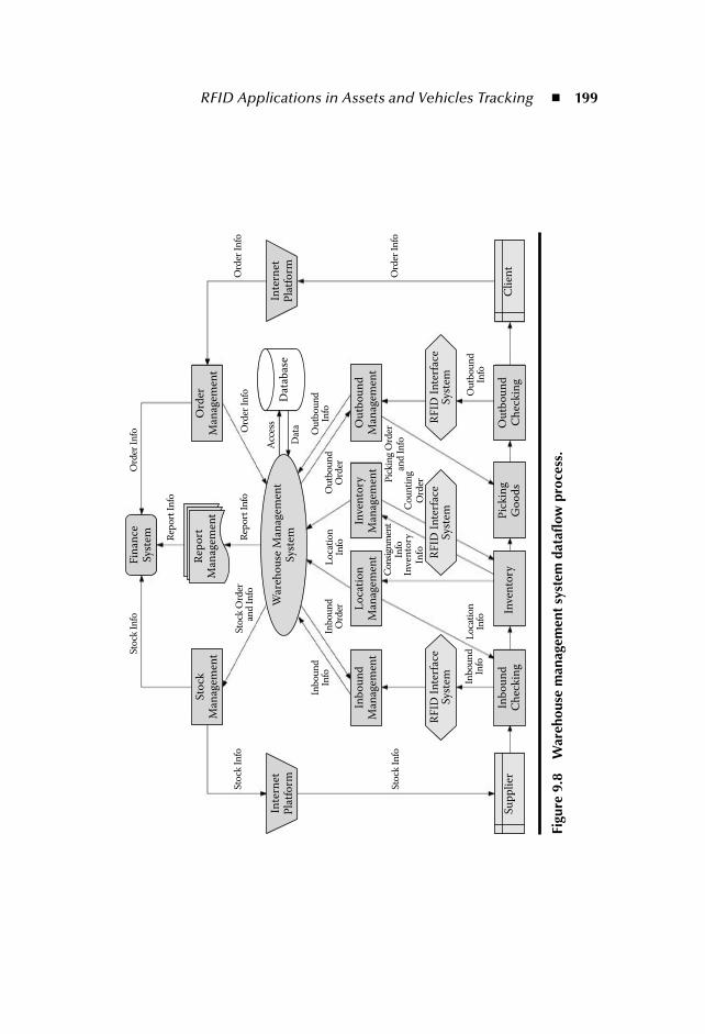
RFID Applications in Assets and Vehicles Tracking 199
Fin
ance
Sys
tem
RF
ID I
nte
rfac
eS
yste
m
Su
pp
lier
Inve
nto
ryIn
bo
un
dC
hec
kin
gO
utb
ou
nd
Ch
eck
ing
Pic
kin
gG
oo
ds
RF
ID I
nte
rfac
eS
yste
mR
FID
In
terf
ace
Sys
tem
Rep
ort
Man
agem
ent
Sto
ckM
anag
emen
tO
rder
Man
agem
ent
Inb
ou
nd
Man
agem
ent
Lo
cati
on
Man
agem
ent
Inve
nto
ryM
anag
emen
tO
utb
ou
nd
Man
agem
ent
Inte
rnet
Pla
tfo
rmIn
tern
etP
latf
orm
Dat
abas
e
Cli
ent
War
eho
use
Man
agem
ent
Sys
temRep
ort
In
fo
Rep
ort
In
foS
tock
In
fo
Sto
ck I
nfo
Sto
ck I
nfo
Ord
er I
nfo
Ord
er I
nfo
Ord
er I
nfo
Ou
tbo
un
dIn
foL
oca
tio
nIn
fo
Lo
cati
on
Info
Pic
kin
g O
rder
and
In
foIn
ven
tory
Info
Ou
tbo
un
dIn
fo
Co
un
tin
gO
rder
Con
sign
men
tIn
fo
Inb
ou
nd
Info
Inb
ou
nd
Info
Ou
tbo
un
dO
rder
Inb
ou
nd
Ord
er
Dat
a
Acc
ess
Sto
ck O
rder
a
nd
In
fo
Ord
er I
nfo
Figu
re 9
.8W
areh
ouse
man
agem
ent
syst
em d
atafl
ow p
roce
ss.
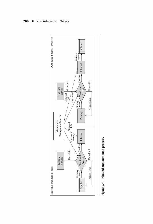
200 The Internet of Things
Inb
ou
nd
Bu
sin
ess
Pro
cess
Ou
tbo
un
d B
usi
nes
s P
roce
ss
Tag
In
foS
ervi
ceT
ag I
nfo
Ser
vice
War
eho
use
Man
agem
ent
Sys
tem
Inb
ou
nd
Inb
ou
nd
Pic
kin
gC
hec
k a
nd
Acc
ept
Ch
eck
an
dA
ccep
tS
up
pli
erC
lien
t
Del
iver
yN
ote
sD
eliv
ery
No
tes
Ret
urn
No
tes
Pu
rch
ase
Ord
erC
lien
t O
rder
Pic
kin
gN
ote
sQ
ual
ified
Qu
alifi
ed
Go
od
s In
foG
oo
ds
Info
Ou
tbo
un
dIn
foIn
bo
un
dIn
fo
Un
qu
alifi
edU
nq
ual
ified
Pic
kin
g A
gain
Figu
re 9
.9In
boun
d an
d ou
tbou
nd p
roce
ss.
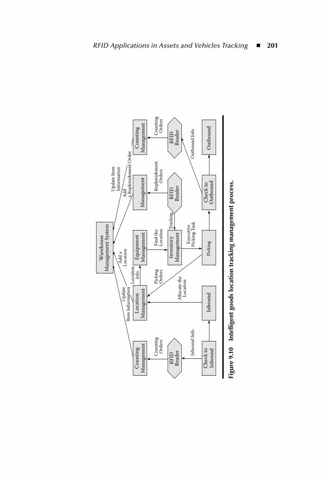
RFID Applications in Assets and Vehicles Tracking 201
War
eho
use
Man
agem
ent
Sys
tem
Ad
d a
Lo
cati
on
Lo
cati
on
Info
All
oca
te t
he
Lo
cati
onPic
kin
gO
rder
sF
ind
th
eL
oca
tio
n Tra
ckin
g
Exe
cuti
veP
ick
ing
Tas
k
Pic
kin
g
Rep
len
ish
men
tO
rder
sC
ou
nti
ng
Ord
ers
Co
un
tin
gO
rder
s
Ou
tbo
un
d I
nfo
Ch
eck
to
Ou
tbo
un
dO
utb
ou
nd
Inb
ou
nd
In
fo
Ad
da
Rep
len
ish
men
t O
rder
Up
dat
eIt
em I
nfo
rmat
ion
Up
dat
e It
emIn
form
atio
n
Co
un
tin
gM
anag
emen
t
RF
IDR
ead
erR
FID
Rea
der
RF
IDR
ead
er
Ch
eck
to
Inb
ou
nd
Inb
ou
nd
Lo
cati
on
Man
agem
ent
Eq
uip
men
tM
anag
emen
t
Inve
nto
ryM
anag
emen
t
Co
un
tin
gM
anag
emen
tM
anag
emen
t
Figu
re 9
.10
Inte
llige
nt g
oods
loca
tion
tra
ckin
g m
anag
emen
t pr
oces
s.
202 The Internet of Things
In reference to the outbound process, the backend warehouse management sys-tem will arrange the outbound task and ensure that the goods are sent to the out-bound area. In the outbound area, the goods are tracked by RFID readers and sentto the packing area to complete the packing task with the permission of the ware-house management system. By the means of monitors throughout the warehouseand the RFID readers fixed on the shelves, it is easy to find the exact location andmaturity of goods to complete the automatic replenishment functions.
9.4.2 Automatic Vehicle IdentificationAn automatic vehicle identification system is more suitable for large-scale manu-facturers, with thousands of vehicles entering and leaving each day. Although anoriginal vehicle monitor system can register the vehicles, it cannot locate the vehi-cles or check the transported goods. RFID-based solutions can integrate vehiclemanagement, logistics management, and tracking and security management forthose large-scale manufacturers.
RFID-based vehicle electronic licenses can be used to take the initiative toefficiently manage vehicles. With the deployment of RFID readers at main gates,both the information of the trucks and their goods can be checked according to thelogistical task in the backend information system. With the deployment of RFIDreaders at the main cross roads, even the location and speed of a vehicle can beobtained, which makes the cost much lower than deployment of the satellite globalpositioning system (GPS) technology on each vehicle. The entire system architec-ture is shown in Figure 9.11.
A RFID electronic license is delivered to each vehicle that is authorized to enterthe enterprise. The license embeds unique and untearable RFID chips, so it can-not be replaced with a false license. Moving vehicles can also be interrogated andexamined. Enterprise security departments can collect vehicle information at dif-ferent gates or places, and check this information with the logistic informationmanagement system. The unmanned sentries at gates connect with alarm systemsto intercept suspicious vehicles, if necessary. With the help of wireless terminalequipment, safeguards can also be set up at temporary checkpoints. Any vehiclepassing the collection areas in an enterprise will be recorded. According to recordsin the information center, any suspicious vehicles can be checked and reported tothe police.
The data and information of the RFID-based vehicle tracking system are col-lected automatically, without manual intervention, thus it can reduce the work-load of safeguards. And, on the other hand, it can effectively avoid the possibilityof collusion. As extension applications, tracking transport vehicles can also beused for tracking goods and getting the current location of possible stolen goods,which is extremely important in preventing the further spread of fake and shoddyproducts.

RFID Applications in Assets and Vehicles Tracking 203
Wir
eles
s tr
ansm
itti
ng
Wir
eles
s tr
ansm
itti
ng
Wir
eles
s tr
ansm
itti
ng
Inb
ou
nd
Ou
tbo
un
d
Ou
tbo
un
d
Mo
nit
or
Info
Mo
nit
or
Info
Mo
nit
or
Info
RF
ID M
on
ito
r
RF
ID M
onit
or
RF
ID M
onit
or
Ser
ver
Ser
ver
Web
Ser
ver
E-L
icen
seT
ag
E-L
icen
seT
ag
E-L
icen
seT
ag
Inte
rnet
Con
sole
Co
nso
le
Da
tab
ase
Inb
ou
nd
Su
pp
ly C
hai
n M
on
ito
r
Figu
re 9
.11
Aut
omat
ic v
ehic
le id
enti
fica
tion
sys
tem
.

204 The Internet of Things
9.5 ConclusionThe application of RFID systems to assets and vehicle tracking in the enterpriseabove is significant to logistics management. Compared with traditional barcodeidentification technology, RFID possesses characteristics, such as reading multi-ple tags once, reading/writing many times, and so on. In logistics management,information accuracy and timeliness are the key concern, which is an advantage ofRFID-based applications. RFID technology enhances the degree of automation ingoods sorting and reduces error ratio, causing the entire enterprise management tobe open and effective. RFID technology reduces theft in the enterprise and givesreasonable reference to the scheduling of vehicles.
In the future we need to perfect the system to handle the challenges listedbelow:
1. It is necessary to prevent unauthorized insertion into the private informa-tion on the RFID tags. In the wireless channel between tags and readersand that of intelligent terminals and management system, there is a lack of asecurity solution to avoid remote eavesdroping on RFID tag information.
2. In the vehicle tracking system, it is credible to manage the vehicles with theRFID license tag. However, the vehicles with false license tags are invisibleto the system since they don’t have RFID data. As a result, it is importantto make the license tag visible to the naked eye or develop more advancedscientific methods to solve this problem.
With the depth and extent of development of RFID technology, it is expectedthat RFID equipment will be multifunctional, small, with rapid transmission ofinformation, etc. Meanwhile, the Internet of things, that support global RFIDinformation exchange will enlarge the scope of RFID-based asset tracking.
References [1] RFID Journal. http://www.rfidjournal.com/, accessed on 10/01/2007.
[2] EPCglobal. http://www.epcglobalinc.org/, accessed on 10/01/2007.[3] Gary M. Gaukler, RFID in Supply Chain Management. Ph.D thesis, Standford
University, 2005. [4] Lai Fujun, Hutchinson Joe, and Zhang Guixian, Radio frequency identification
(RFID) in China: opportunities and challenges, International Journal of Retail and Distribution Management, 33, 2005:905–916(12).
[5] Magnus Holmqvist and Gunnar Stefanssone, Mobile RFID—A case from volvo oninnovation in SCM, Proceedings of the 39th Annual Hawaii International Conference on System Sciences 2006 (HICSS ’06), Kauai, Nawaii vol. 6, January 2006.
[6] Zhang Ting, Xiong Zhang, and Ouyang yuanxin, A framework of networkedRFID system supporting location tracking, 2nd IEEE/IFIP International Conference in Central Asia on the Internet, 2006, Tashkent, Uzbekistan, pp. 1–4.
RFID Applications in Assets and Vehicles Tracking 205
[7] R. Angles. RFID technologies: supply-chain applications and implementationissues, Information Systems Management, 22 1:51–65, 2005.
[8] Nova Ahmed, Rajnish Kumar, Robert Steven French, and UmakishoreRamachandran, RFID: A reliable middleware framework for RFID deployment,Proceeding of IEEE International Parallel & Distributed Processing Symposium(IPDPS 2007), Long Beach, CA, March 2007.
[9] Young-Jun Seo, Deuk Kyoung Oum, and Peom Park, Bridging the real world withthe RFID phone—Focus on development of innovative man machine interfaceand abundant wireless Internet service, Proceedings of the 6th IEEE International Conference on Computer and Information Technology, Seoul, Korea, September 2006.
[10] Yi Tianchen, Ai Minyu, Raymod Lai N, and Dou Xuechen, Application of WLANin JTAV, Proceeding of IEEE International Symposium on Microwave, Antenna, Prop-agation and EMC Technologies for Wireless Communications, Beijing, China, August2005.
[11] R. Kalden, I. Meirick, and M. Meyer, Wireless internet access based on GPRS,IEEE personal communications, April 2000.
[12] Raj Bridgelall, Enabling mobile commerce through pervasive communicationswith ubiquitous RF tags, Proceeding of IEEE Wireless Comunication and Networking Conference 2003 (WCNC 2003) New Orleans, LA, March 2003, 3:2041–2046.
[13] B.S. Prabhu, Xiaoyong Su, Charlie Qiu, et al., WinRFID: A middleware for theenablement of radio frequency identification (RFID)-based applications, Wireless and Sensor Networks: Technology, Applications and Future Directions. John Wiley &Sons, 2005.
[14] Evan Welbourne, Magdalena Balazinska, et al., Challenges for pervasive RFID-based infrastructures, Fifth Annual IEEE International Conference Pervasive Com-puting and Communications Workshops (PerCom Workshop 2007), White Plains,NY, 388–394, March, 2007.

207
Chapter 10
RFID Enabled Logistics Services
Zongwei Luo, Edward C. Wong, C.J. Tan, S.J. Zhou, William Cheung, and Jiming Liu
Contents10.1 Introduction ......................................................................................20810.2 Pervasive Services Trend .........................................................................21010.3 Open Issues and Opportunities .............................................................. 211
10.3.1 Trustworthiness Research .......................................................... 21110.3.2 Issues and Opportunities............................................................213
10.4 Trustworthy SOA ...................................................................................21310.4.1 Trustworthy Service Framework ................................................21410.4.2 Design Rationale........................................................................21410.4.3 Pervasive Logistics Services Enabling Capabilities...................... 215
10.5 Case Study: RFID-Enabled Logistics Services........................................21610.5.1 Resource Constraint...................................................................21610.5.2 Implementation Hardship..........................................................21710.5.3 Privacy Concerns .......................................................................21710.5.4 Data Collision............................................................................21710.5.5 Our Demonstration ...................................................................218

208 The Internet of Things
In this chapter, we introduce the concept of trustworthy pervasive services for enablingnext generation E-logistics, the key enabler for improving and streamlining logisticsoperations. In pervasive services-enabled E-logistics, trustworthiness establishment isusually under resource constraints, presenting challenges for mutual trust establish-ment as well as data dependability. Thus, we will focus on security for mutual trust anddata dependability aspects of pervasive service trustworthiness. We will present mutualauthentication protocols for mutual trust establishment and a collaborative model fordata dependability resolving data collision problems in pervasive service environments.
10.1 IntroductionAs the world is becoming increasingly interconnected and interdependent, logistics riseup as the fundamental enabler for increasingly global economy connecting worldwideparticipates involving suppliers, factories, warehouses, distribution centers, retailers,and service and solution providers. As the Pearl River Delta (PRD) continues to growas a manufacturing center for the world, Hong Kong has the opportunity to remainand grow as a logistics and enterprise headquarters hub. At the same time, HongKong is faced with mounting pressure to effectively manage and control disparate,international, and increasingly complex logistics networks and processes.
As a result of this increasing globalization of trade and manufacturing, systemintegration for logistics and supply chain management have garnered the interestof both researchers and practitioners. To enable global trading and manufactur-ing, there has been a renewed interest in devising and putting into practice inte-grated systems to consolidate all the isolated logistics systems. Thus, an integratedand developed environment is foreseen for enabling such a worldwide logistics andsupply chain network development.
10.6 Mutual Authentication for Mutual Trust................................................21810.6.1 Lightweight Mutual Authentication Protocol[24] .......................219
10.6.1.1 Initialization ...............................................................21910.6.1.2 Protocol Procedures ................................................... 220
10.6.2 Related Work ............................................................................ 22010.6.3 Further Discussion.....................................................................221
10.7 Data Collision and Dependability ......................................................... 22210.7.1 Dense RFID Reader Environment ............................................ 22210.7.2 Data Collision Problem............................................................. 22210.7.3 Proposed Anticollision Schemes .................................................22310.7.4 Establishing the Collision Model ...............................................22510.7.5 Modeling the Collision States ................................................... 22610.7.6 The Anticollision Solution..........................................................227
10.8 Conclusion ........................................................................................228References ...................................................................................................228

RFID Enabled Logistics Services 209
Logistics industry has been and continues to look for information technology(IT) systems and solutions to bridge three flows (physical goods, cash, and infor-mation), streamlining the supply chains by integrating transportation, distributioncenters, retailers and manufacturers. Built upon the networked logistics systems,modern logistics demand more and more professional logistics services in orderto improve profitability and competitiveness. These logistics services diversify andpenetrate into all domains of logistics management in order to enhance resourceutilization and reducing operational cost [1]. As evidence of this trend, IDC researchreported that a third of logistics services segments are keeping involved and beingrefined [1]. We predict, in the future, that current networked logistics will no doubtbe involved in the next generation of E-logistics dominated by pervasive logisticsservices.
This new pervasive logistics services paradigm promises more flexible andadaptable logistics; available anywhere, anytime, and in any means, these perva-sive logistics services ride upon networked logistics systems, making it possible fororganizations to better align IT resources with business priorities. This, in turn,demands seamless and/or dynamically created trustworthy communication andinterconnections among logistics participants. In this chapter, we will illustratethis pervasive logistics service vision and present a trustworthy pervasive serviceframework for logistics.
To accomplish this, an architecture supporting the evolution of system develop-ment and easy integration of new and legacy systems is needed. Thus, we proposethe adoption of Service-Oriented Architecture (SOA), utilizing technologies, suchas Web service-based infrastructure, repository, and application development, todevelop a trustworthy environment. This will enable the design, implementation,and control of logistics information essential to the delivery of logistics systems.
MR2MR3Information Panel Information
Panel PMR MR1
Visiting NodeVehicular Area
NetworkVisiting Network(a Passenger’s PAN)
Figure 10.1 Interconnected networks for pervasive services.

210 The Internet of Things
The chapter sections are as follows:
10.2: Pervasive Services Trend 10.3: Open Issues and Opportunities 10.4: Trustworthy SOA 10.5: Case Study—RFID-Enabled Logistics Services 10.6: Mutual Authentication for Mutual Trust 10.7: Data Collision and Dependability 10.8: Conclusion
10.2 Pervasive Services TrendPervasive services are emerging as the next paradigm for distributed and mobilecomputing, which are seamlessly available anywhere, anytime, and in any format.Logistics enterprises are also evolving towards the SOA trend, to offer logisticsservices over logistics networks. There is a need for mechanisms to connect thelogistics networks and applications, and to enable logistics services over the logis-tics networks and allow access to services provided by these networks. The perva-sive logistics services mechanisms will eventually allow dynamic and cost-effectivecreation of interconnections of disparate logistics network systems and processesresulting in improved efficiency in networks and applications development anddeployment.
Logistics industry is pressing for such solutions, e.g., for realizing multivendor,multiplatform interoperability. Challenges are to reduce the time, risk, and costof interoperability between disparate applications and devices from multiple ven-dors on multiple platforms. In light of these challenges, Fujitsu [2], for example,has been developing a SOA-based pervasive retailing framework for enabling retailstore operations.
The pervasive logistics services vision has received strong support from theindustry. Radio Frequency IDentification (RFID) technology, the pervasive infra-structure enabler for global supply chain visibility, is predicted to revolutionize themodern supply chain and logistics operations. With the introduction of ElectronicProduct Code (EPC) and as the global RFID standards mature, more and morecompanies are preparing to leverage RFID to integrate it into their supply chains fora competitive edge. RFID/EPC, the technology for the next generation of “Internetof Things,” provides opportunities for new applications, services, and solutions overthe next generation Internet. We see the trend of convergence of computing andcommunication, requiring for advanced service enabling technologies with mobil-ity support, and service differentiation and secure communications.
Moving toward this pervasive vision, research and development activities arevisible and yield substantial results in pervasive computing. Early work includesproviding capabilities for dynamic networking of devices. IBM has offered aframework to allow a diverse set of devices to connect via open network standards

RFID Enabled Logistics Services 211
to enterprise data and applications anytime and anywhere [3]. Microsoft alsoplanned to form a platform that promises to deliver convergence among disparatecommunications technologies [4]. Recently, Cisco and IBM planned to promoteindustry adoption of unified communications and collaboration, an important steptoward enabling pervasive services [5].
10.3 Open Issues and OpportunitiesIn the pervasive services environment, it is predicted that users tend to be mobileand typically access resources and services using various tools and devices. Key chal-lenges include the managing of security and of access control. As the logistics servicebecomes pervasive, trustworthiness of these services is becoming increasingly impor-tant as trust exists pervasively in the dynamic interactions and collaborations amonglogistics participants. Thus, in the following, we will identify research issues in devel-oping trustworthy pervasive logistics services via reviewing related works.
10.3.1 Trustworthiness ResearchSubstantial research activities are reported in the domain of trust ranging fromdirect experiences and recommendations approaches to other dimensions, such
Visiting Network(PAN)
Vehicular AreaNetwork (VAN)
MR2
MR1
PMR3
Visiting Node
Local Node
PMR2
PMR1
Figure 10.2 Pervasive service access.

212 The Internet of Things
as security. Recommendations for managing context-dependent and subjectivetrust is described in [6]. Distributed trust based on direct monitoring is also pro-posed in combination with utility and importance of the situation [7]. In [8], theauthors provide a rating process for trust. Distributed trust models for managingtrust with quantitative a scheme using distributed recommendations was reportedin [7]. In [9], the authors described a formal model for trust formation, evolution,and propagation. Game theory and distributed algorithmic mechanism design isreported in [10] to calculate trustworthiness based on reputation. Decision mod-ules were also designed and integrated for assessment [11–13].
Research activities on security trust aspects are also reported. Frameworks resis-tant to attack for building up trust systems can be seen in [14–16]. Proposals forintrusion detection system (IDS) by extending it to an ad hoc wireless environmentcan be found in [17]. Distributed authentication mechanisms [18] are needed fordevices, which cannot be trusted unless there is first-hand evidence.
Industry development on trust in pervasive services has been centered on Webservices security and trust management. In 2002, VeriSign unveiled a trust servicesframework to enable trusted Web services [5,7] with support from major playersincluding BEA , HP , IBM, Microsoft , Oracle , Sun Microsystems and web-Methods . Web Services Trust Language (WS-Trust) [19] provides extensions toWS-Security to secure a communication between two parties for trust relation-ships. It represents the industrywide efforts in Web Services trust. In WS-Trust,
CN
VAN
Home NetworkPMR
Home NetworkMR2
MR2
Node
PMR
HA_PMR
HA_MR2
PAN
(1)
(2)
(3)
(4)
(5)
Figure 10.3 Secure channels for data access.
RFID Enabled Logistics Services 213
the two parties must exchange security credentials; however, each party still has todetermine if they can trust the asserted credentials of the other party.
10.3.2 Issues and OpportunitiesIn summary, while many proposals exist for building trust pervasive services, thereare various issues related to those proposals, such as:
Many trust models, as well as frameworks, lack adaptability, the key tosupporting pervasive services trustworthiness. As pointed out by manyresearchers, they were often designed for specific scenarios. This makesthese proposals difficult to be deployed in different environments.They lack methods on how the trust models and frameworks can be appliedin various scenarios. Solutions are needed to build trust relationships thatcan be used in evaluating trust for various applications.Many trust models and frameworks cover comprehensive elements, whichare quite useful in trust evaluation. However, these elements are scattered inmany different dimensions, lacking interconnections and interdependencyanalysis between them. There needs to be a demonstration on how a trust-worthy pervasive service can be built out of the interdependent elements inthe trust models.
Essentially, while we need a holistic view of integrating various trust elementsand form a trustworthy environment, we have to bridge the gaps between thevarious trust models proposed, realization of various trust elements, and system-atic deployment of trustworthy solutions for a trustworthy environment. We willaddress the issues by developing a service framework to allow transparent trustwor-thy pervasive services development. Further, to illustrate the framework feasibility,we will, using sensing networks services as an example, focus on the realization ofsecurity and dependability of aspects of pervasive service trustworthiness.
10.4 Trustworthy SOAPervasive logistics services are often based on SOA, an architecture supporting theevolution of system development and easy integration of new and legacy systems.SOA methodologies help enable more flexible and responsive IT environments tosupport the demands of pervasive logistics services.
In critical and ubiquitous infrastructure-enabled logistics and supply chainmanagement-related processes and services, resource constraint has been a key concernin developing secure pervasive services. We will present a realization for a lightweightsecurity protocol for mutual trust among pervasive services. To further enhance the

214 The Internet of Things
mutual authentication protocols, a concept is presented for a collaborative model fordata dependability resolving data collision problems in pervasive service environments.
10.4.1 Trustworthy Service FrameworkWe develop Trustworthy Service-Oriented Architecture (SOA-Trust) for the nextgeneration logistics network infrastructure to streamline the pervasive logistics ser-vices development and delivery, technology deployment, localization, and adoption.A SOA-Trust framework includes three layers of abstractions: (1) the trustworthyservice models, (2) the trustworthy interactions, and (3) service realization proxies.SOA-Trust extends the work in [20], including a metamiddleware service frame-work for autonomous service provisioning, which provides secure communicationfor mutual trust and data dependability.
SOA-Trust provides brokerage functions necessary in finding and using servicesprovided by the middleware framework. To meet the challenges, such as hetero-geneity and usability for pervasive service brokering, we use service descriptiontechnologies and annotation languages, like Web Service Description Language(WSDL), to provide an information abstraction layer for the pervasive services bro-kerage. It describes and correlates pervasive services provided through the WSDLand annotation, faciliating assurance of the functional consistency of the pervasiveservices provided by different system developers.
The SOA-Trust brokers make the decisions involving service resources over multiplepervasive services. The core module is the brokering engine driving the orchestrationengine to execute the brokering plans with brokering logics (algorithms) and context.Depending on the different nature of the middleware service request, the service brokerin turn invokes one of the specific brokers to help fulfill the service request.
The SOA-Trust will provide services for secure event processing to supportstreaming capabilities. It abstracts the event processing functions into messaging,logics, and context. These functions are concerned with more than data reductionoperations, such as filtering, aggregation, and counting. Functions, such as mutualauthentications and data dependability, are provided for mutual trust amongpervasive services. Each of these functions will be the features supported by themiddleware as well as functional components published in the SOA-Trust serviceframework.
The processing messaging mainly concerns the message streaming protocol. Theprocess logics contain algorithms to handle the message streams for filtering, aggre-gation, counting, etc. The process context establishes the trustworthy relationshipsfor the streaming patterns among the event processing modules.
10.4.2 Design RationaleSOA-Trust intends to provide flexibilities to open up opportunities for effectivelyreconfiguring and orchestrating pervasive services at a metalevel for supporting more
RFID Enabled Logistics Services 215
agile and scalable development of distributed systems. The SOA-Trust frameworkthat is building up the pervasive logistics service infrastructure is characterized as:
SOA-Trust is built upon a foundation of global standards, best practices, andmethodologies of service-oriented computing. Leveraging SOA, it providesevolutionary architecture for building the pervasive logistics services infra-structure. SOA-Trust offers a provision framework for new components, tech-nologies, and services, and facilitates the solution and system deployment. SOA-Trust ensures the consistency in finding and using information andservices in the logistics networks. In SOA-Trust, resources are made avail-able to other participants in the network as independent services that areaccessed in a standardized way. This provides for more flexible loose cou-pling of pervasive service resources.
SOA-Trust intends to help build logistics services to address the followingchallenges:
Challenges in adopting present and upcoming standards (e.g., RFID, EPC),which are still evolving. Not prepared for adaptation with new components, technologies, and ser-vices, and is limited in its ability to reuse existing components and services. Challenges in its consistency to find and use information and services. Challenges in legacy application and data integration to preserve the orga-nizations’ IT investment when they migrate to pervasive infrastructure. Not scalable and not prepared for large-scale pervasive technologydeployments.
SOA-Trust offers service framework to turn an organization’s existing and newapplications and data sources into a pervasive logistics services infrastructure. Itaids technology in localizing and adapting to create a more modular and flexibleset of interfaces for the ongoing conversion to pervasive services. SOA-Trust enablesevolution of pervasive solutions over time. It provides important benefits for scal-able pervasive service implementations and system deployment. SOA-Trust enablesend-to-end solutions that can help achieve improved business efficiencies by apply-ing pervasive services to logistics business processes in the related business logics.
10.4.3 Pervasive Logistics Services Enabling CapabilitiesSOA-Trust promises an effective and trustworthy approach to seamless integrationand orchestration of distributed resources for dynamic business processes along thesupply chains. The integration and adaptation needs of next generation E-logisticsare addressed by a middleware integration framework [20,21] in SOA-Trust. Thisservice-oriented intelligent middleware service framework fulfills the needs of how

216 The Internet of Things
to embed the autonomy-oriented computing paradigm in the framework to enableautonomous service brokering and composition for highly dynamic integrationamong heterogeneous middleware systems [20,21].
10.5 Case Study: RFID-Enabled Logistics ServicesRecently renewed interests in RFID has turned logistics industry’s attention topotential benefits from real-time logistics information visibility. The up-to-the-second or -minute information status of available inventory and goods deliverysupports better logistics services and planning. Also, delivery vehicles installedwith global positioning system (GPS) sensors allow their locations to be accuratelytracked for more effective fleet management. While the involved sensor technolo-gies have been becoming more mature in recent years, integrating them togetherfor building E-logistics infrastructures and networks demands middleware frame-works that enable different parties to communicate and collaborate in an efficientand effective manner. SOA-Trust helps to provide the following functions in orderto take full advantage of what RFID can promise:
Reactivity: RFID and EPC technologies have promised real-time globalinformation visibility for E-logistics participants. To benefit from such vis-ibility, the E-logistics participants will be able to identify the interestedsituations and react to each situation when it happens. The event will bereported and notification will be sent to interested E-logistics participants. Integration: System integration and maintenance burdens increase with thenumber of choices of the RFID middleware systems available to interfacewith the E-logistics systems. The challenges posed by such middleware pro-liferation and heterogeneity as well as how dynamic logistics environmentimpose certain architectural and functional requirements are addressed inSOA-Trust [20]. Adaptability: SOA-Trust enables evolution of pervasive solutions overtime. It adopts the autonomic service provisioning capabilities to furtherenhance its adaptability for scalable pervasive service implementations andsystem deployment [20,21].
However, there are still other challenges that need to be addressed in the pro-cess to fully develop trustworthy RFID-enabled logistics systems and solutions.
10.5.1 Resource ConstraintThe low cost demanded for RFID tags, the power restrictions, and being nonresis-tant to physical tampering are common limits in the RFID system. Therefore, mosttraditional security schemes widely used in Internet or existing applications are
RFID Enabled Logistics Services 217
not feasible in RFID environments. Some lightweight and resource-saving securitymechanisms must be imposed on the RFID tags and readers to address the authen-tication and privacy problems.
10.5.2 Implementation HardshipThe low cost demanded for RFID tags causes them to be very resource-limited. Thepower restrictions and the nonresistance to physical tampering also make RFID systemsvulnerable to passive and active attacks. Moreover, tags being short of cryptographicfunctions makes the traditional security schemes that is widely used in Internet or exist-ing applications unfeasible in RFID environments as well. According to [20,23], typicaltags that can only store hundreds of bits of data, roughly have between 5,000 and 10,000logic gates. Within this gate counting, only between 250 and 3,000 gates can be devotedto security functions, including random number generation, encryption or decryption,hash operation, etc. This limited resource results in popular cryptographic algorithms,including Data Encryption Standard (DES), Advanced Encryption Standard (AES),public cryptographic algorithms (e.g., RSA and ECC), and cannot be easily implementedin low-cost tags. For example, it was reported that for a standard implementation of theAES between 20,000 and 30,000 gates are needed [20,23].
10.5.3 Privacy ConcernsPowerful track and trace capabilities promised by RFID tags create new threatsto user privacy. The bogus identity also increases risks for RFID applications. As aresult, some light weight and resource-saving security mechanisms must be imposedon the RFID tags to address the authentication and privacy problems in RFIDand in [22,23], authors proposed a few privacy solutions. In [24,25], the authorsprovided detailed discussions on a XOR-based, lightweight mutual authenticationRFID protocol. The primary advantage of the protocol proposed in [24,25] is that itonly needs simple Hash operation, XOR, and random number generation for bothtag and reader (or backend system). This simple function can be implemented easilyin passive tags with little incremental cost. Another strong point of the protocol isthat the read/write access is integrated into the protocol. This makes it very suitableto the applications in which each tag has many restricted access memory blocks. Itsresource-saving feature, scalability, and high performance meet the requirements inmetering and payment of E-commerce applications.
10.5.4 Data CollisionMany readers in a RFID application form a reader network through which readerscan send the data to a backend system. However, reader collision problems cannot be
218 The Internet of Things
avoided in such multireader RFID environments. Unlike the tag collision problem,which has been widely discussed in existing research, the impact of reader collisionis not regarded as important as tag collision because it seldom required multireadersin the past few years. For improving read rate and correctness, several readers areput together to form a dense RFID reader environment. In a dense reader environ-ment, reader collision is also becoming a key issue for the application of RFID.The current RFID reader network is a centralized model in which any message isstreamed to a single, central backend system.
10.5.5 Our DemonstrationIn the following sections, realizations for the trust elements, such as mutualauthentication for mutual trust and data dependability, are provided to supporttrustworthy RFID-enabled logistics system and application development. Thesetrust elements will be orchestrated and invoked by the brokerage systems in theSOA-Trust to form end-to-end supply chain solutions.
The scenario of the demonstration is as follows:
In RFID-enabled pervasive logistics services, RFID readers will communi-cate with tags and other readers. In this RFID network, trust relationships have to exist between the RFIDreaders and tags. Before the communication begins, pervasive logistics services participants(i.e., readers and tags) have to authenticate with each other to establish cor-responding trusted relationships. However, there are risks in the trusted relationship established only throughthe very first “say hello” authentication. For example, a Denial of Service(DoS) attack resulting from data collision would pose a threat to datadependability in the communication. Thus, trust mechanisms are neededfor data reliability to maintain the trusted relationship. The authentication protocol and data dependability solution are trust ser-vices developed in the SOA-Trust framework.
10.6 Mutual Authentication for Mutual TrustAlthough there are many authentication protocols already proposed, their imple-mentation is not satisfactory when deploying on a real RFID system. The simpleauthentication protocol in RFID is based on a tag’s physical feature. Tags them-selves have no access control function, thus, any reader can freely obtain informa-tion from them. As a result, an authentication (as well as authorization) schememust be established between the reader and the tag so as to achieve the privacy

RFID Enabled Logistics Services 219
issue of a RFID system. Since the communication between a tag and a reader isby radio, anyone can access the tag and obtain its output, i.e., attackers can eaves-drop on the communication channel between tags and readers, which is a cause ofconsumer apprehension. So, the authentication scheme employed in RFID mustbe able to protect the data passing between the tag and the reader, i.e., the schemeitself should have some kind of encryption capability.
RFID readers may only read tags from within the short tag operating range(e.g., 3m), the reader-to-tag (or forward channel) is assumed to be broadcast witha signal strong enough to monitor from long range, perhaps 100. The tag-to-reader(or backward channel) is relatively weaker and may only be monitored by eaves-droppers within the tag’s shorter operating range. Generally, it will be assumed thateavesdroppers may only monitor the forward channel without detection.
10.6.1 Lightweight Mutual Authentication Protocol[24]Before presenting the overall protocol, we make the following assumptions. First, itis assumed that each tag has k readable and writable blocks. Second, each tag storesthe following information:
Tag identification is used to identify a tag. Transaction counter c with initial value of 1 will be increased by 1 aftereach successful transaction. R is the randomly generated number. W is the workable area. The secret is shared with the backend database or system with the initialvalue.
We also assume that each tag shares two public hash functions, H and G, andwith the backend system.
In the following, the lightweight challenge-response protocol [24,25] adaptedto the limited resource criteria of a passive tag is illustrated as below.
10.6.1.1 Initialization
Assume a passive tag contains three workable regions (e.g., W1, W2, and W3)opened for both reading/writing. At the very beginning, beside the EPC code,each tag comes with an initial secret information, s0, and a transaction counter, c(usually a 8 to 20 byte number depending on the output length of the hash functionG), which will be used by the backend for tag verification. On the other hand, thebackend stores lists of information on each tag that it can work with. That pieceof information basically contains a tag’s initial secret information s0 and workableregion(s) Wk, where k belongs to 1, the number of workable regions.

220 The Internet of Things
10.6.1.2 Protocol Procedures
For Ith transaction, the backend sends a read/write request to the tag. The tag responds with both the transaction counter value ci and the hashedoutput G{si ci} back to the backend. From the received transaction counter ci, the backend first does hashing s0for ci times in order to get sbi and then calculates the hash output G{sbiXOR ci} by iterating each tag stored. Then, it compares the value betweenG{sbi XOR ci} and G{si XOR ci} and the equality holds if and only if sbisi, which means that the remote tag is authenticated by the backend. Once finding the matching tag, the backend generates a random sessionnumber, R, and makes the output containing three elements, R XORG{sbi}, G{sbi XOR R XOR Wk} and Wk, and sends them back to the tag. The tag can get back Rt from element R XOR G{sbi} by doing XOR with itsinternal hashed si. Then, it calculates the hash output G{si XOR Rt XOR Wk}to see whether the value is equal to G{sbi XOR R XOR Wk} or not. Again,the equality holds if and only if si sbi and Rt R, which means that thebackend is also authenticated by the tag. At this point, the mutual authenti-cation procedure is completed and a common random session number, R, isbeing agreed and setup between the tag and the backend for data encryption.It should be noticed that the authorization is also achieved since Wk defineswhat regions are opened for reading/writing within this transaction. Since mutual authentication is established, it is ready to begin data transferbetween the tag and the backend. To protect the data passing inbetween, therandom session number, R, is employed as a key for doing the encryption forthat purpose. For each data to be transferred, the sending party (the tag forread query case and the backend for write query case) produces two elements,G{R} XOR data and G{data}. On the other hand, once receiving these ele-ments, the received party (the backend for read query case and the tag forwrite query case) can retrieve back the data by doing XOR with G{R} XORdata and then verify its value by hashing it and comparing it with G{data}. Finally, the tag will increment the transaction counter, ci, by 1 and updatethe secret information from si to si 1 by hashing it using H function aftercurrent data transfer phase is completed.
10.6.2 Related WorkA unique serial number is a popular means for developing authentication protocols.In this scheme, each tag must hold a PIN or PIN list. The PIN-based authentica-tion is similar to kill and sleep [26] in which each tag stores a unique PIN in itslocal memory. While authenticating with the reader, the tag will send its PIN tothe reader for authentication. Unlike the PIN-based scheme, in the PIN list-based

RFID Enabled Logistics Services 221
authentication, which is also similar to minimalist cryptograph method addressedin [27], every tag stores a list of PINs and each time it will randomly select a PINfrom the list to authenticate with the reader. However, both the replay attack andthe physical tampering can easily breach the authentication. Moreover, no mutualauthentication is provided in unique serial number-based authentication protocol.
Hash-based authentication protocol is similar with our scheme. Differentapproaches include hash-lock [28,29], semirandomized hash-lock [30], random-ized hash-lock [31], and hash-chain [32]. Other hash-based solutions are also dis-cussed in [33–36]. All of these protocols rely on synchronized secrets residing onthe tag and backend server and require a one-way hash function from the tag. Theseapproaches show how guaranteeing the untraceability by updating tag identifierwould increase the workload of backend servers. Compared with our hash-basedprotocol, these existing authentication protocols do not integrate reading and writ-ing requirements with authentication.
The challenge–response-based authentication protocols are also similar with ourscheme. Many different transformation techniques were used to provide securityduring the challenge or response process. The transformations include asymmetriccryptography, XOR [22,37], hash function [38–40], and physical unclonable func-tions [41]. Like existing hash-based schemes, current challenge–response-basedauthentication protocols do not provide the integration properties of reading andwriting with authentication.
Some other authentication protocol in RFID include HB (Hopper and Blum)and HB-enhanced [42,43], a list of licit readers approach, noisy approach [44],silent tree walking and backward channel key negotiation [28,29], and active infor-mation exchanging [45]. However, these existing solutions are only feasible in somegiven RFID applications and not general to any RFID application. The securityof these protocols is not yet proved theoretically. For the detail of these existingprotocols, readers can refer to [46].
10.6.3 Further DiscussionTo summarize, most of the above methods are not likely to be a fully satisfactorysolution. Thus, it seems imperative to explore alternatives to get a workable scheme.While the lightweight mutual authentication proposed in [24,25] has the strengthof a resource-saving feature, scalability, and high performance, it is possible thatattackers can capture and log the authentication messages by sniffing the commu-nication between tags and readers. Then, attackers, in personating the identity ofthe legal tag, can replay the message of the authentication protocol to the backendsystem. Although this type of attack could be easily mitigated due to the randomlygenerated information to protect the exchanged messages, it could lead to potentialDoS attacks. That is, attackers can sniff the communication and resend the messageto the party. In this way, it is possible to put the system out of service. Attackers can

222 The Internet of Things
also destroy the synchronization of the security protocol, pose which can a DoS riskto the RFID systems.
DoS attacks seem hard to mitigate. Only if there are strict access controls inwhich sniffing, message replay, or jamming is not possible, a DoS attack risk canbe minimized. A mechanism for checking the message received and message filter-ing, i.e., data filtering and anticollision, are also methods to reduce this risk. Thus,in the following section, we will discuss techniques to avoid data collision to helpmitigate the DoS attack.
10.7 Data Collision and DependabilityIn this section, we will focus on reader collision problems by enhancing the datadependability. It relies on a collaborative peer-to-peer network for solving readercollision problems in dense RFID reader environments [47]. It is a fully distrib-uted and self-organized overlay network. The model can be used in a dense readerenvironment to exchange information directly among readers without any centralcontrol or intermediation. In RFID systems, the interference refers to the collisionof different radio signals with the same frequency, which will lead to distortedsignals. Occasionally, if tags or a reader broadcast the same frequency radio signal,collisions will happen. The RFID internal interference, (RFID collision problem)contains tag-to-tag, tag-reader, and reader-to-reader collision.
10.7.1 Dense RFID Reader EnvironmentDense RFID reader environment refers to the RFID application scenes in whichmultiple readers are deployed in a predetermined place to provide highly reli-able and correct reading of tags. In regular RFID environments, one reader isenough to scan and read multiple tags. However, a single reader sometimes cannotprovide high read rate while keeping the correctness of reading if multiple tagsstream into the reader’s reading zone; for example, misreadings and crashed read-ing results are common in such a RFID application. For the purpose of improvingthe read rate and correctness, several readers are put together to form a denserreader environment.
10.7.2 Data Collision ProblemReader collision problems are rooted in the limited frequencies available to RFIDreaders and tags. Unlike other wireless communication techniques, although RFIDoperates at different frequencies and the choice of frequency depends on the appli-cation, it is not a free choice as radio frequencies are strictly regulated. Regulations
RFID Enabled Logistics Services 223
are, of course, needed in order to avoid interference between the different radio sys-tems. In order to provide interoperability worldwide, a variety of specific frequenciesfor RFID have been declared. These are known as ISM frequencies (Industrial–Sci-entific–Medical) [48]. The reason for this is that they were gratis in most countriesand represented a selection of low, intermediate, and high frequencies, allowing forRFID systems with different purposes. Therefore, the limited available frequenciesprevent separating each reader to operate under different frequencies. At the sametime, low-cost tags are also short of selective frequencies, which also leads to readercollision.
Other than the above factors, we also believe the lack of information exchangesamong RFID readers inevitably sharpens the circumstance of reader collision.While there is no direct information exchange among readers, the reader’s currentstatus is not fully utilized by other readers. First, readers can collaborate with eachother to reduce the misreading and enhance their reading performance. Second,readers can work together to reduce or eliminate reader collision in dense readerenvironments. Finally, readers can exchange the reading list, a list of tags beingread, with other readers to reduce redundant reading. All together, if an infrastruc-ture is available for readers to exchange information directly, it is likely to reduceor eliminate reader collision.
10.7.3 Proposed Anticollision SchemesTo the best of our knowledge, the pioneering work about multireaders and theirrelated reader collision problem can be found in [49,50], and a short survey ofRFID collision, especially tag collision, was given in [51]. In [49,50], the authorsfor the first time addressed the RFID interference and reader collision problem.In theory, the reader collision problem is equivalent to the co-channel frequencyassignment problem, which, in turn, is equivalent to the simple graph coloring prob-lem. Because the graph coloring problem is a well-known NP problem, the authoraddressed two approximate methods: centralized approximate algorithms and localapproximate algorithms. In [52], the authors addressed two enhanced graph color-ing based schemes to schedule the various RFID readers in the network.
The anticollision methods mentioned in [49,50] and their enhancing versionsare useful in small scale and static RFID environments. One disadvantage of thecentralized approximate methods is the need of predistribution of the allocation.Hence, they cannot be generally used in RFID applications. The distributed greedyalgorithm is the one which is most similar to our dynamic anticollision scheme.However, they do not address how to exchange the frequency each reader uses. Tothe contrary, we not only build an interconnected reader network to distribute thereader’s information, but also construct a dynamic anticollision scheme. In general,both the high computation and the inadaptability limit coloring approaches inRFID applications.

224 The Internet of Things
Waldrop et al. [53,54] are also the first works (Colorwave) to address reader col-lision problem. In particularly, it is a time division multiple access-based (TDMA)anti collision algorithm. In Colorwave, first a reader collision network must beconstructed. Then the reader collision problem is reduced to a classic coloring prob-lem in graph theory, which is the same used in [49,50]. PULSE [55,56] is anotherTDMA-based anticollision scheme. In PULSE protocol, it assumes that there aretwo separate communication channels: data and control.
Listen Before Talk (LBT) is a Carrier Sense Multiple Access-based (CSMA)anticollision protocol defined in ETSI EN 302 208 [57], which is an evolvingstandard being developed for RFID readers. Like normal CSMA, in LBT, beforequerying the tag, the reader first listens on the data channel for any ongoing com-munication for a specified minimum time. The theoretical analysis for reader col-lision and LBT method appears in [58]. The CSMA-based anticollision approachis addressed in [59].
The Class I Generation 2 UHF standard [53] addressed by EPCGlobal [60,61]uses spectral schemes, i.e., it is based on FDMA (Frequency Division MultipleAccess). It separates the reader transmissions and the tag transmissions spectrallysuch that tags collide with tags, but not with readers and readers collide with readersbut not with tags. However, most of the low-cost tags do not have frequency selec-tivity. Hence, when two readers using separate frequency communicate with thetag simultaneously, this leads to collision at the tags. Thus, multiple readers-to-taginterferences still exist in this standard.
Q-Learning [62] is a hierarchical, online learning algorithm that finds dynamicsolutions to the reader collision problem by learning the collision patterns of thereaders and by effectively assigning frequencies over time to the readers. This pro-tocol maintains a hierarchical structure, which will require extra managementoverhead. Q-Learning assumes collision detection for readers. However, in ourdynamic antischeme, we addressed how to detect collision in dense reader envi-ronments. The complicated structure also makes it unsuitable for general RFIDapplications.
Naive sending mentioned in [59] is similar to the random backoff addressedin [49,50]. In naive sending, each reader transmits a reader-tag inventory requestif only if it needs to send. If either reader-to-reader collisions or reader-to-tag col-lisions occur, the conflicted readers must resend the query again at freely or atconstant intervals. Naive sending is quite prone to both reader–tag collision andreader–reader collisions. Ransom sending [59] is an improved version of naivesending. In this method, randomization in sending and resending is used to reducethe chance of collision. Thus, if the readers choose to back off for a random intervalbefore sending a read command, the probability of collision may be lower. Since thedifferent readers choose to send data after random intervals, the sending from tworeaders would probably not be concurrent, given that they independently choosetheir resending interval.
RFID Enabled Logistics Services 225
10.7.4 Establishing the Collision ModelIn order to eliminate or reduce reader collision, current reader networks can bemodeled as a collaborative network for a reader to directly exchange informationwith other readers. Other than the reader collision, some other problems occurringin current dense reader environments can also easily be resolved if such an informa-tion exchanging infrastructure is available. Peer-to-peer computing (P2P) technol-ogy is a preferred distributed scheme for the collaborative network. P2P is alsoregarded as a distributed model for information exchange. Therefore, in this sec-tion we present a collaborative peer-to-peer network for the reader collision prob-lem in dense RFID reader environments. This novel model is constructed on theRFID reader collision model such that it is a fully distributed and self-organizedoverlay network. Our new model can be used in dense reader environments toexchange information directly between readers without any central control orintermediation.
Although a simple reader collision network cannot resolve the problem ofreader collision, we can make use of it to build a high efficient anticollision net-work. If two readers potentially interfere with each other, either reader-to-readercollision or reader-to-tag collision, we connect these two readers by an undirectededge. After building the reader collision network, a central server can periodicallyremove or disable some readers to avoid a reader collision problem, which can eas-ily use the methods in [49,50]. However, a simple static schedule will result in amisreading problem in multitag and dense reader RFID applications. Moreover,reader’s individual anticollision capacity cannot efficiently resolve the problem ofreader collision in dense reader environments. If we can build an interconnectedcollaborative network, it would be beneficial to also design a high efficient anticol-lision scheme.
After the construction of a reader collision network (RCN), the interconnectedRFID reader collision model (IRCM) can be built on RCN [47]. For the sake ofstationary RFID reader networks, each reader can periodically update its collisionneighbor and routing neighbor by the above algorithm. Therefore, it is unnecessaryfor additional update and maintenance protocol for IRCM. For a dynamic RFIDreader network in which some readers may intentionally or unintentionally crashdown, a separate update and maintenance protocol is helpful. We will take that itinto account farther in our future research works.
Because of collision, including tag collision and reader collision, not all readers’queries will receive an anticipated response. For example, if a reader–tag collisionoccurs during a readers’ reading period, no response will be sent to the readersbecause the interrogated tag does not know which reader is interrogating it. Simi-larly, during read-reader collision, tags are unaware of how to reply.
Some research programs have worked out a number of solutions for tag collision.Therefore, the tag collision can either be avoided or its impact on correct read could
226 The Internet of Things
be precomputed before the deployment of a RFID system. In both cases, the impactcannot be changed. Although the impact of other environmental factors varies withdifferent RFID applications, its effect will become more and more insignificant withthe improvement of the quality of manufacture and the rationality of deployment.
10.7.5 Modeling the Collision StatesThe correct read rate of a reader during a given period is defined as Query-HitRatio, denoted as QT. Reader’s Normal Query-Hit Ratio (NQT), denoted asQTn, is defined as the proximate value of QT while the reader operates withoutreader collision. By our definition, the value of NQT is always equal or less than1(QTn 1). In practice, ordinary NQT is always less than 1 because we cannot getrid of all the artificial impacts. The actual value of QTn varies with diverse readers.We also suppose that QTn for a given reader can be computed in experimentalRFID environments. Generally, in practical RFID environments, we can safelyassume that no reader occurs while QT belongs to the range of (QTn, 1). We alsoassume that if reader collision happens, the QT drops down as well. The lower thevalue of QT the more collisions that the reader encounters. Therefore, each readercan compare its current QT value with the normal QT value (QTn) to estimate ifit will come up against a collision problem or not. If QT is less or equal to QTn,it speculates that some collisions will occur. By carefully computing the differencevalue between QT and NQT, a reader can also be capable of determining thedeterioration of collision.
We also determined the extent of collision and semicollision. Reader’s semicol-lision threshold (QTt) is defined as the lowest value of QT while the reader operateswith semireader collision. For semicollision, we define a semicollision threshold asQTt. While the QT follows into the range of (QTn, QTt], the reader is in a semi-collision state. If collision happens so frequently that misreading and other per-formances are greatly reduced, we can conjecture that reader collision occurs withhigh probability. Therefore, the reader changes to a disabled state, in which it stopsinterrogating tags and frees its whole reading cycle or frequencies for other read-ers. The threshold of disabled state is QTf. If QT is less or equal to QTf, a readerchanges to a disabled state automatically. Therefore, a reader’s disabled threshold(QTf) is defined as the lowest value of QT while the reader stops interrogating anytag. To sum up, each reader has the following states:
Initialization state: Before the running of a RFID system, all readers remainin this special situation. Only when the RFID system starts running, willthe reader change its state to a normal state. Normal state: When switched on, readers will go into the normal state inwhich they will query and read tags as if there is no collision. As long as QTis greater than QTn, a reader keeps itself in a normal state.
RFID Enabled Logistics Services 227
Seminormal state: State in which some collisions do occur, but it is not soserious that it will result in numerous misreading. When QT drops belowQTn but is not larger than QTt, a reader changes its state from normal tosemicollision. While the collisionis mitigated and QT is larger than QTn,the reader will change back to a normal state. Collision State: State in which a serious collision has happened and resultsin slight misreading errors. Only when QT drops below QTt will the readerchange its state from semicollision to collision. However, depending on thevariety of QT, a reader will change its state to a disabled or semicollisionstate. If QT continuously drops below QTf, a reader stops its reading andchanges to a disabled state. Contrarily, if QT goes up greater than QTt, thereader restores back to its semicollision state. Disable state: State in which the reader stops querying and reading tags. Areader keeps itself in this state for some time. If timeout occurs, it automati-cally resumes to collision state. End state (or stop state): If we power off the reader, it comes into a stop stateand all tasks are ended as well.
10.7.6 The Anticollision SolutionIn the process of developing dynamic anticollision schemes, we assume that eachreader has a controllable reading speed, denoted as V, the number of reads per sec-ond. The reading speed decides how fast a reader can query and read tags within itsvicinity. The difference between reading speed and query hit rate is that the latterrefers to how successful the reading is. Actually, reader speed is tightly related toreader collision. In dense reader environments, high reading speed may result inhighreader collision. For example, when two readers encounter a collision prob-lem, if one reader reduces its reading speed, the probability of a collision will alsodecrease. Further, if one reader stops reading, the collision will disappear.
Accordingly, we can shift the reader into different states to force it to read withdifferent speeds. This way, the collision can be reduced or avoided. Apparently, if anyreader independently changes its state according to the above transition diagram, ithas the same effect as naive send or random sending anticollision schemes [59].
Clearly three controllable and adjustable parameters (QTn, QTt, and QTf)could be used to control the transition. By adjusting these values, a reader willchange to a different state. For improving the performance of anticollision, it isbetter for each reader to decide how to change its state by combining local andglobal states. For that reason, in our dynamic anticollision scheme, each readerperiodically announces its local state to other readers though the interconnectedRFID reader collision model (IRCD) constructed above. After receiving otherreaders’ information states, a reader can adjust the value of the three controllableparameters synthetically to change its state and, thus, change its reading speed toavoid collision or reduce the probability of a collision.

228 The Internet of Things
10.8 ConclusionIn this chapter, a trustworthy pervasive service framework for E-logistics infrastructureand network integration and development has been introduced. It is designed to enablemore responsive supply chains and better planning and management of complex inter-related systems. The proposed adoption of SOA can support the evolution of logisticsinformation system development and easy integration of new and legacy systems.
We take a holistic view of integrating various trust elements to develop theSOA-Trust framework to bridge the gaps among the various trust model proposed,realization of various trust elements, and systematic deployment for a trustworthyenvironment. SOA-Trust supports the evolution of system development and easyintegration of new and legacy systems. SOA methodologies help enable more flex-ible and responsive IT environments to support the demands of pervasive logisticsservices.
In a critical and ubiquitous infrastructure enabled logistics and supply chainmanagement-related processes and services, resource constraint has been a key con-cern in developing secure pervasive services. We realize that there is a need for alightweight security protocol for mutual trust among pervasive services. To furtherenhance the mutual authentication protocols, SOA-Trust addresses the data colli-sion and dependability problem, yet another major concern. Also presented in thischapter is the desire for a collaborative model for data dependability resolving datacollision problems in pervasive service environments.
References [1] http://www.idc.com/getdoc.jsp?containerId CN383107N [2] http://www.fujitsu.com/us/news/pr/ftxs_20060116-1.html [3] http://www-128.ibm.com/developerworks/web/library/wa-pvc/ [4] http://www.engadget.com/2006/06/26/microsoft-unveils-unified-communica-
tions-platform/ [5] http://www.eetasia.com/ART_8800455871_499495_2ba350a0200703.HTM [6] A. Abdul-Rahman and S. Hailes. Using recommendations for managing trust in
distributed systems. In Proceedings of IEEE Malaysia International Conference onCommunication, Kuala Lumpur, Malaysia, November 1997.
[7] A. Pirzada and C. McDonald, Establishing trust in pure ad-hoc networks. In Pro-ceedings of the 27th Conference on Australasian Computer Science, vol. 26, pp. 47–54,Dunedin, New Zealand, 2004.
[8] S. Buchegger and J.-Y.L. Boudec. A robust reputation system for p2p and mobilead-hoc networks. In Proceedings of the 2nd Workshop on the Economics of Peer-to-Peer Systems, Cambridge, MA, June 2004.
[9] M. Carbone, M. Nielsen, and V. Sassone. A formal model for trust in dynamicnetworks. In Proceedings of the 1st IEEE International Conference on Software Engi-neering and Formal Methods, pp. 54–63, Brisbane, Australia, September 2003.

RFID Enabled Logistics Services 229
[10] H. Sun and J. Song, Strategy-proof trust management in wireless ad hoc net-work. In Proceedings of the IEEE Canadian Conference on Computer and ElectricalEngineering, Niagara Falls, ON, 2004.
[11] N. Dimmock. How much is “enough?” Risk in trust-based access control. In Pro-ceedings of the 12th IEEE International Workshop on Enabling Technologies, p. 281,Washington, D.C., June 2003.
[12] D. Quercia, and S. Hailes. MATE: Mobility and adaptation with trust and expected-utility. International Journal of Internet Technology and Secured Transactions, vol. 1,pp. 43–53, 2007.
[13] D. Quercia and S. Hailes. Risk aware decision framework for trusted mobile inter-actions. In Proceedings of the 1st IEEE/CreateNet International Workshop on theValue of Security through Collaboration, Athens, Greece, September 2005.
[14] J.R. Douceur. The Sybil attack. In Proceedings of the 1st International Workshop onPeer-to-Peer Systems, pp. 251–260, Cambridge, MA, March 2002. Springer-Verlag,Heildelberg, Germany.
[15] J. Liu and V. Issarny. Enhanced reputation mechanism for mobile ad hoc networks.In Proceedings of the 2nd International Conference on Trust Management, vol. 2995,pp. 4862, Oxford, U.K., March. 2004. LNCS.
[16] J.-M. Seigneur and C.D. Jensen. Trading privacy for trust. In Proceedings of the2nd International Conference on Trust Management, vol. 2995, pp. 93–107, 2004.Springer-Verlag, Heidelberg, Germany.
[17] P. Kannadiga, M. Zulkernine, and S. Ahamed, Towards an intrusion detection system forpervasive computing environments. In Proceedings of the International Conference on Infor-mation Technology (ITCC), pp. 277–282, IEEE CS Press, Las Vegas, NV, April 2005.
[18] H. Luo, P. Zerfos, J. Kong, S. Lu, and L. Zhang, Selfsecuring ad hoc wireless net-works. In Proceedings of the Seventh IEEE International Symposium on Computersand Communications (ISCC’02), Taormina Giardini Naxos, Italy, pp. 567, 2002.
[19] http://specs.xmlsoap.org/ws/2005/02/trust/WS-Trust.pdf [20] Z. Luo, J. Li, C.J. Tan, F. Tong, A. Kwok, E. Wong, and H. Wang. Intelligent
service middleware framework. In Proceedings of the 2006 IEEE Conference on Ser-vice Operation, Logistics and Informatics, June 21–23, pp. 1113–1118. Los Alamitos:IEEE Computer Society Press.
[21] Z. Luo, M. Wang, W.K. Cheung, J. Liu, F. Tong, and C.J. Tan, An agent-mediatedmiddleware service framework for e-logistics. Book Chapter in Advance Series inE-business (ASEB), 2007 (in print).
[22] P. Peris-Lopez, J.C. Hernandez-Castro, J. Estevez-Tapiador, and A. Ribagorda. RFIDsystems: A survey on security threats and proposed solutions. International Conferenceon Personal Wireless Communications (PWC’06), Albacete, Spain, September 2006.
[23] P. Peris-Lopez, J.C. Hernandez-Castro, J.M. Estevez-Tapiador, and A. Ribagorda.LMAP: A real lightweight mutual authentication protocol for low-cost RFID tags,Workshop on RFID Security, Graz, Austria, 2006.
[24] Z. Luo, T. Chan, and J. Li, A lightweight mutual authentication protocol for RFIDnetworks. Proceedings of ICEBE 2005, Beijing, China, 2005.
[25] Z. Luo, T. Chan, J.S. Li, E. Wong, W. Cheung, V. Ng, and W. Fok, Experimentalanalysis of an RFID security protocol. The 2006 IEEE International Conference one-Business Engineering (ICEBE 2006), Shanghai, China, 2006.

230 The Internet of Things
[26] A. Juels. Strengthening EPC Tags Against Cloning. In M. Jakobsson and R.Poovendran, eds., ACM Workshop on Wireless Security (WiSe), pp. 67–76, 2005.
[27] A. Juels, Minimalist cryptography for low-cost RFID tags. In Proc. 4th Int. Conf.Security Commun. Netw., C. Blundo and S. Cimato, Eds. New York: Springer-Verlag, 2004, vol. 3352, Lecture Notes in Computer Science, pp. 149–164.
[28] Weis, “Security and Privacy in Radio-Frequency Identification Devices,” Master’sthesis, MIT, Cambridge, MA, 2003.
[29] S. Weis, S. Sarma, R. Rivest, and D. Engels, Security and privacy aspects of low-cost radio frequency identification systems, International Conference on Security inPervasive Computing, March 2003, Fort Worths TX, pp. 454–469.
[30] S.M. Lee, Y.J. Hwang, D.H. Lee, and J.I. Lim, Efficient authentication for low-costRFID systems. International Conference on Computational Science and its Applica-tions (ICCSA 2005), Singapore, 2005, pp. 619–627.
[31] M. Ohkubo, K. Suzuki, and S. Kinoshita. Cryptographic approach to privacy-friendly tags. In RFID Privacy Workshop, MIT, MA, 2003.
[32] M. Ohkubo, K. Suzuki, and S. Kinoshita, Efficient hash-chain based RFID privacyprotection scheme, in Proc. Int. Conf. Ubiquitous Computing, Nottingham, U.K., 2004.
[33] G. Avoine and P. Oechslin, A scalable and provably secure hash based RFIDprotocol. The International Workshop on Pervasive Computing and CommunicationSecurity, Kauai Island, Hawaii, 2005, pp. 110–114.
[34] E.Y. Choi, S.M. Lee, and D.H. Lee, Efficient RFID authentication protocol forubiquitous computing environment. The International Workshop on Security inUbiquitous Computing Systems, Nagasaki, Japan, 2005. Proceedings Lecture Notesin Computer Science 3823, Springer, 2005.
[35] S. Lee, T. Asano, and K. Kim, RFID mutual authentication scheme based on syn-chronized secret information. In Symposium on Cryptography and Information Secu-rity, Hiroshima, Japan, 2006.
[36] M. Ohkubo, K. Suzuki, and S. Kinoshita, Cryptographic approach to privacyfriendly tags. In RFID Privacy Workshop, MIT, Cambridge, MA, 2003.
[37] I. Vajda, and L. Buttyn, Lightweight authentication protocols for low-cost RFIDtags. Workshop on Security in Ubiquitous Computing, 2003.
[38] T. Dimitriou, A lightweight RFID protocol to protect against traceability andcloning attacks. The Conference on Security and Privacy for Emerging Areas in Com-munication Networks, Athens, Greece, 2005.
[39] D.N. Duc, J. Park, H. Lee, and K. Kim, Enhancing Security of EPCglobal Gen-2RFID tag against traceability and cloning. The 2006 Symposium on Cryptographyand Information Security, Hiroshima, Japan, 2006.
[40] D. Henrici and P. Miller, Hash-based enhancement of location privacy for radiofrequency identification devices using varying identifiers. International Work-shop on Pervasive Computing and Communication Security, Orlando, FL, 2004,pp. 149–153.
[41] D. Ranasinghe, D. Engels, and P. Cole, Security and privacy: Modest proposals forlow-cost RFID systems. In Auto-ID Labs Research Workshop, Zurich, Switzerland,2004.
[42] J. Katz and J.S. Shin, Parallel and concurrent security of the HB and HB proto-cols. Advances in Cryptology—EUROCRYPT’06, Saint Petersburg, Russia, 2006.

RFID Enabled Logistics Services 231
[43] S. Piramuthu, HB and related lightweight authentication protocols for secureRFID tag/reader authentication. In Collaborative Electronic Commerce Technologyand Research, Basel, Switzerland, 2006.
[44] C. Castelluccia and G. Avoine. Noisy tags: A pretty good key exchange protocol forrfid tags. The 7th IFIP Conference in Smart Card Research and Advanced Application,Terragona, Spain, April 2006.
[45] V. Natarajan, A. Balasubramanian, S. Mishra, and R. Sridhar, Security for energyconstrained RFID system. The Fourth IEEE Workshop on Automatic IdentificationAdvanced Technologies (AutoID’05), Buffalo, NY, 2005, pp. 181–186.
[46] M. Lehtonen, T. Staake, F. Michahelles, and E. Fleisch. From identification toauthentication—A review of RFID product authentication techniques. Workshopon RFID Security, 2006.
[47] S. Zhou, Z. Luo, E. Wong, and C.J. Tan, Interconnected RFID reader collisionmodel and its application in reader anti-collision, IEEE RFID Conference, Dallas,Texas, March 2007.
[48] K. Finkenzeller. RFID Handbook 2nd ed. John Wiley & Sons, 195–219, 2003. [49] D.W. Engels. The reader collision problem, AUTO-ID Center White paper, http://
autoid.mit.edu/whitepapers/MIT-AUTOID-WH-007.PDF, 2002. [50] D.W. Engels, and S.E. Sarma, The reader collision problem. IEEE International
Conference on Systems, Man and Cybernetics, Hammamet, Tunisia, October. 2002. [51] Y. Yuan, Z. Yang, Z. He, and J. He, Taxonomy and survey of RFID anti-collision
protocols, Computer Communications, 29 (2006), 2150–2166.[ 52] V. Deolalikar, M. Mesarina, J. Recker, D. Das, and S. Pradhan, Perturbative time
and frequency allocations for RFID reader networks. in HP Lab Technical Report,Palo Alto, CA, 2005.
[53] J. Waldrop, D.W. Engels, and S.E. Sarma, Colorwave: An anticollision algorithmfor the reader collision problem. In IEEE International Conference on Communica-tions (ICC’03), Ottawa, Canada, 2003, pp. 1206–1210.
[54] J. Waldrop, D.W. Engels, and S.E. Sanna. Colorwave: A MAC for RFID readernetworks. In IEEE Wireless Communications and Networking Conference (WCNC),New Orleans, LA, 2003. pp. 1701–1704.
[55] S.M. Birari and S. Iyer. PULSE: A MAC protocol for RFID Networks. First Inter-national Workshop on RFID and Ubiquitous Sensor Networks (USN), Nagasaki,Japan, December 2005.
[56] S.M. Birari and S. Iyer. Mitigating the reader collision problem in RFID networkswith mobile readers. In 13th IEEE International Conference on Networks, KualaLumpur, Malaysia, 2005, pp. 463–468.
[57] ETSI EN 302 208-1 v1.1.1, September 2004. CTAN:http://www.etsi.org [58] K.S. Leong, M.L. Ng, and P.H. Cole. The reader collision problem in RFID sys-
tems, IEEE International Symposium on Microwave, Antenna, Propagation and EMCTechnologies for Wireless Communications (MAPE 2005), pp. 658–661, Beijing,China, August 2005.
[59] S. Jain and S.R. Das. Collision avoidance in a dense RFID network. In Proceedingsof the 1st International Workshop on Wireless Network Testbeds, Experimental Evalu-ation and Characterization. Los Angeles, CA, 2006, pp. 49–56.
232 The Internet of Things
[60] EPC Generation 1 Tag Data Standards v. 1.1 Rev.1.27, EPC Global, Tech. Rep., May2005.
[61] EPC Radio-Frequency Identity Protocols Class-1 Generation-2 UHF RFID Proto-col for Communications at 860 MHz–960 MHz V 1.0.9, EPC Global, Tech. Rep.,January 2005.
[62] H. Junius, D.W. Engels and S.E. Sarma, HiQ: A hierarchical Q-learning algorithmto solve the reader collision problem, In Proceedings of the International Symposiumon Applications and the Internet Workshop, January 2006, pp. 88–91, Phoenix, AZ,2006.
[63] G. Tsudik, YA-TRAP: Yet another trivial RFID authentication protocol. Interna-tional Conference on Pervasive Comput. and Comm., Pisa, Italy, 2006.
[64] D. Gupta J. LeBrun, P. Mohapatra, and C.-N. Chuah. Reader collision avoid-ance mechanism in ubiquitous sensor and RFID networks. In Proceedings of the 1stInternational Workshop on Wireless Network Testbeds, Experimental Evaluation andCharacterization, International Conference on Mobile Computing and Networking,Los Angeles, CA, 2006, pp. 101–102.
[65] S.-R. Lee, S.-D. Joo and C.-W. Lee, An enhanced dynamic framed slotted ALOHAalgorithm for RFID tag identification. The Second Annual International Conferenceon Mobile and Ubiquitous Systems: Networking and Services (MobiQuitous 2005).San Diego, CA, 2005, pp. 166–174.
[66] D.R. Hush and C. Wood, Analysis of tree algorithms for RFID arbitration. InProceedings of the IEEE International Symposium on Information Theory, Cambridge,MA, 1998, p. 107.
[67] B. Carbunar, M.K. Ramanathan, M. Koyuturk, C. Hoffmann, and A. Grama,Redundant reader elimination in RFID systems. In Proceedings of Sensor and AdHoc Communications and Networks (IEEE SECON 2005), Santa Clara, CA 2005,pp. 176–184.
[68] F. Wang and P. Liu. Temporal management of RFID data. In Proceedings of the31st International Conference on Very Large Databases, Trondheim, Norway 2005,pp. 1128–1139.
[69] S. Chawathe, V. Krishnamurthyy, S. Ramachandrany, and S. Sarma. ManagingRFID data. In Proceedings of 30th VLDB Conference, Toronto, Canada, 2004,pp. 1189–1195.
[70] J.D. Porter, R.E. Billo, and M.H. Mickle, Effect of active interference on the per-formance of radio frequency identification systems, Int. J. Radio Frequency Identi-fication Technology and Applications, 1, 1: 4–23, 2006.
[71] J. Rao, S. Doraiswamy, H. Thakkar, and L.S. Colby. A deferred cleansing methodfor RFID data analytics. In the Proceedings of the 32nd International Conference onVery Large Data Bases, Seoul, Korea, 2006, pp. 175–186.

233
Chapter 11
Location Trackingin an Office Environment: The Nationwide Case Study
Irene Lopez de Vallejo, Stephen Hailes, Ruth Conroy-Dalton, and Alan Penn
Contents11.1 Introduction ......................................................................................... 23411.2 The Case Study: Nationwide Headquarters, Swindon.............................235
11.2.1 Nationwide House and the Office Environment ........................23611.2.2 The Technology..........................................................................23811.2.3 Communication Strategy ...........................................................241
11.3 Studying the Pilot...................................................................................24311.3.1 Objectives ..................................................................................24311.3.2 Methods.....................................................................................243
11.4 Results of the Technology Pilot ..............................................................24511.5 Results of the Study ................................................................................247
11.5.1 Understanding and Communication..........................................24711.5.2 The Temporary Nature of the Deployment ................................24811.5.3 Privacy and Intrusion.................................................................24811.5.4 Attitudes and Organizational Culture........................................249

234 The Internet of Things
This chapter focuses on studying organizational, social, spatial, temporal, andtechnical issues related to the deployment of location tracking systems in an officeenvironment.
We have investigated and present findings on how workers perceive the experi-ence of the surveillance and understand the scope of the deployment, the reality ofwearing a tag, the pervasive nature of the organizational culture, and its influencein the attitudes observed.
We have explored these issues using an ethnographic approach and qualitativemethods, participant observation, and interviews. The fieldwork has been carriedout in a real office setting and has taken the form of a case study.
11.1 Introduction Included in this chapter are the findings of a detailed case study conducted at theheadquarters of Nationwide, in Swindon, United Kingdom. Participant observa-tion, in-depth interviews, and examination of location tracking data were usedto build a detailed, mainly qualitative, picture of how attitudes and behaviors areaffected by the deployment of a pervasive technology. Attitudes of the workers par-ticipating in the study are explored to provide a context in which to analyze theimpact of a location tracking system in the relationship between workers and thesocial dynamics they build through and around their physical environment.
The main findings are grouped around a number of issues:
1. Social, spatial, and temporal issues affecting the performance of the loca-tion tracking system
2. Privacy, transparency, and control: what do we fear, what can we see, andwho do we think is in charge
3. The pervasiveness of the organizational culture and its mark on the accep-tance of the deployment
4. Attitudes toward the technology project
The conclusions focus around recommendations for the development anddeployment of indoor location-tracking systems, implications for workplace design,
11.6 Conclusions ............................................................................................25011.6.1 Conclusions Regarding the Pilot ................................................25011.6.2 Conclusions Regarding the Study of the Pilot ............................25111.6.3 Conclusions Regarding the Approach to the Study of the Pilot..253
11.7 Open Issues ............................................................................................253Acknowledgments.............................................................................................254Bibliography......................................................................................................254

Location Tracking in an Office Environment 235
and the case for the development of a multidisciplinary theoretical framework. Wealso discuss methodological and practical limitations of the study and close thechapter highlighting possible paths of research that have come out of the currentreflection.
11.2 The Case Study: Nationwide Headquarters, Swindon
Nationwide is one of the biggest financial institutions in the United Kingdom.As with many others, Nationwide is today faced with a changing and competi-tive market in which technology can provide an advantage; thus, technologicalawareness is a priority for Nationwide and other such businesses. Their motivationmay range from the need to update old fashioned systems, increase performance ordecrease cost, or both, to the simple desire to position themselves at the forefrontof technology adopters in their area. These factors are leading organizations, suchas Nationwide, to acquire and deploy highly sophisticated technologies inside theirbuildings; technologies exciting current interest include VoIP, Wireless, Sensor net-works, and RFID (Radio Frequency*). One of the capabilities that such technolo-gies can provide is accurate real-time information on the location of objects andindividuals.
Today, facilities managers working for efficiently run organizations in big, com-plex buildings regularly conduct space occupation and space use studies in order tounderstand numbers of people in different areas of the building to be able to man-age the use of space and, ultimately, to make informed decisions on investment inproperty. In addition, these studies contribute to planning health and safety anddisaster discovery procedures.
The methods used today are manual, it being common use to employ observerswho count people and note observations in templates or building plans. In publicareas of buildings, the studies focus on headcounts (number of people) distributedby location (entrance, exit, hall, restaurant, ATM, etc.) and time slots. In officeenvironments, the studies usually center on space utilization (occupation and usageof space), counting the number of people in a particular space (desk, meeting room,cafeteria area) over time.
Current approaches to acquire location data are unable to capture sufficientlyrich information to give organizations the accurate picture of individuals’ locationsand movements across space needed to build an understanding of overall spaceutilization. They are also time consuming, obtrusive, and resource intensive. Orga-nizations also want to understand spatial relationships inside the building, not only
* It should be acknowledged that, while this chapter adopts a primarily resource-based view ofthe organization, individuals and groups within organizations may have motivations at vari-ance to the imperatives of the wider organization.

236 The Internet of Things
in terms of simple location and movement, but of relations between them and withthe working environment.
Accurate real-time location and tracking technologies, therefore, are of particu-lar interest to large organizations, such as Nationwide. Knowing, in real-time, thelocation of their workers gives companies “the option of measuring, understanding,monitoring and managing their buildings better, and the chance to investigate therelationships of the building to the day to day experience of each employee overtime”* From a corporate perspective, ideally such a system would be able to locateand track individuals in space with such a precision that it is possible to get livecoverage of their movements and interactions. It would record these events andallow postprocessing and analysis. Clearly the capabilities of these technologies tomonitor the behavior of individual staff raises certain ethical issues.
In order to address these issues, Nationwide set up a highly ambitious and noveltechnology pilot project in 2005 that continued in 2006, The Smart Building Project.The project had three operational phases:
Phase I: Install and test a passive RFID security system to monitor num-bers of staff moving in and out the pilot area.Phase II: Test and apply “tags’’ to assets and link the individual tags tocross reference of ownership.Phase III: Install and test a location tracking system using active tags andultrawide band (UWB) radio signals to monitor the position and move-ment of staff within the pilot area.
This case study focuses on the deployment carried out in Phase III, in whichthe spatial and social arrangements surrounding the introduction and deploymentfor six weeks of an UWB system was studied. This ultrawideband system wasdeveloped and provided by the technology supplier Ubisense, and will be referredto as the “Ubisense system.”
11.2.1 Nationwide House and the Office EnvironmentThe Ubisense system was installed in Nationwide’s headquarters building, Nation-wide House, a purpose built structure on the outskirts of Swindon. The buildinghas lower ground, ground, first, and second floors. It is open 24 hours a day, 7 daysa week. Its main feature as a building is a street-like layout incorporating a third ofthe ground floor area. This is the main public space of the building in which theshared facilities are concentrated. An Internet cafe, restaurant, convenience shop,and coffee vending machines are located along the main street area.
The pilot was conducted on one wing of the second floor, Block A (see Figure 11.1and Figure 11.2). This space is shared by three different departments: Property
* Quotation from a Nationwide internal document.
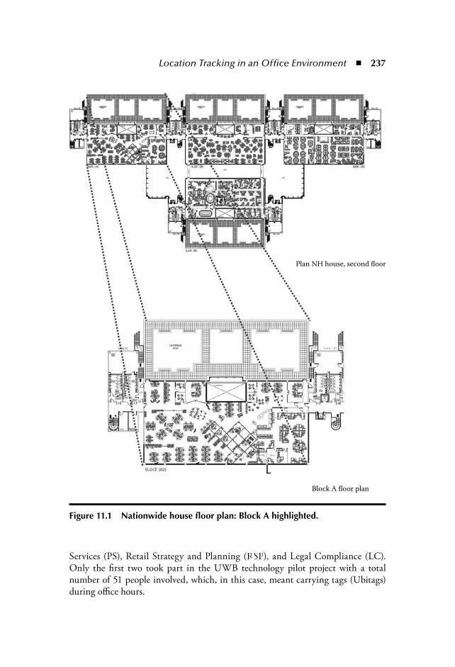
Location Tracking in an Office Environment 237
Services (PS), Retail Strategy and Planning (RSP), and Legal Compliance (LC).Only the first two took part in the UWB technology pilot project with a totalnumber of 51 people involved, which, in this case, meant carrying tags (Ubitags)during office hours.
Plan NH house, second floor
Block A floor plan
Figure 11.1 Nationwide house floor plan: Block A highlighted.
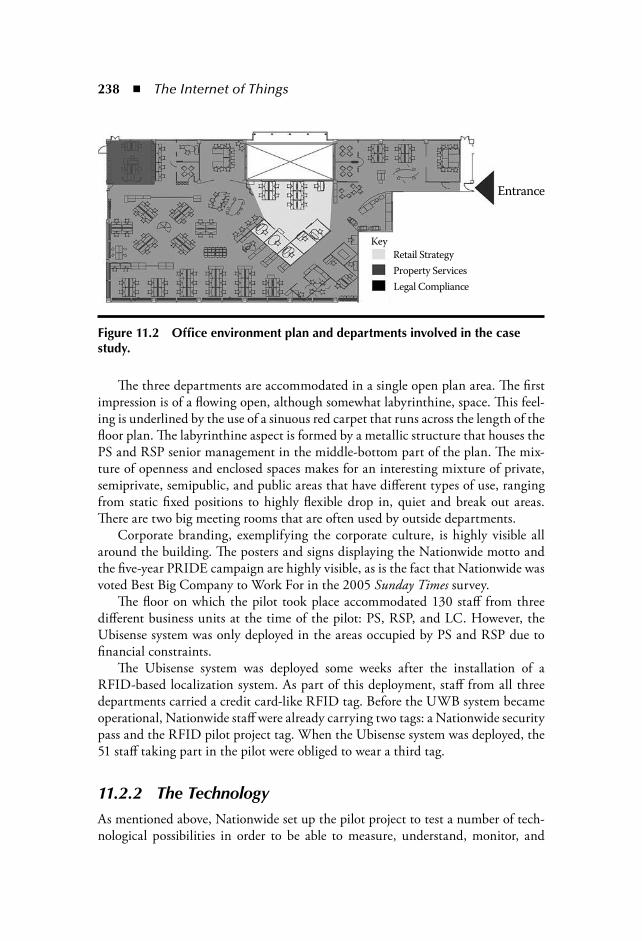
238 The Internet of Things
The three departments are accommodated in a single open plan area. The firstimpression is of a flowing open, although somewhat labyrinthine, space. This feel-ing is underlined by the use of a sinuous red carpet that runs across the length of thefloor plan. The labyrinthine aspect is formed by a metallic structure that houses thePS and RSP senior management in the middle-bottom part of the plan. The mix-ture of openness and enclosed spaces makes for an interesting mixture of private,semiprivate, semipublic, and public areas that have different types of use, rangingfrom static fixed positions to highly flexible drop in, quiet and break out areas.There are two big meeting rooms that are often used by outside departments.
Corporate branding, exemplifying the corporate culture, is highly visible allaround the building. The posters and signs displaying the Nationwide motto andthe five-year PRIDE campaign are highly visible, as is the fact that Nationwide wasvoted Best Big Company to Work For in the 2005 Sunday Times survey.
The floor on which the pilot took place accommodated 130 staff from threedifferent business units at the time of the pilot: PS, RSP, and LC. However, theUbisense system was only deployed in the areas occupied by PS and RSP due tofinancial constraints.
The Ubisense system was deployed some weeks after the installation of aRFID-based localization system. As part of this deployment, staff from all threedepartments carried a credit card-like RFID tag. Before the UWB system becameoperational, Nationwide staff were already carrying two tags: a Nationwide securitypass and the RFID pilot project tag. When the Ubisense system was deployed, the51 staff taking part in the pilot were obliged to wear a third tag.
11.2.2 The TechnologyAs mentioned above, Nationwide set up the pilot project to test a number of tech-nological possibilities in order to be able to measure, understand, monitor, and
Entrance
Key
Retail Strategy
Property Services
Legal Compliance
Figure 11.2 Office environment plan and departments involved in the case study.
Location Tracking in an Office Environment 239
manage their buildings, how they operate, and their relationship to the day-to-dayexperience of each employee over time. The Ubisense system was deployed for atotal period of six weeks as a temporary technology pilot. Nationwide was inter-ested in the potential for the system to be mobile and easily deployed in differentfloors and buildings.
The system uses ultrawideband radio to determine locations of people and/orassets in indoor environments. Radio pulses are transmitted from tags worn byemployees as they move about the office environment. The pulses are received bysensors mounted around the periphery of the building or rooms within the build-ing and these calculate the position of the tags in real-time. The location data canbe used in this raw form or it can be used to determine location events, i.e., whendid a person enter the 1 m 1 m zone in front of a desk, or how long was a personin a corridor zone. In the trial, all the data gathered was stored in a conventionalSQL (structured query language) database.
The reliability of the locations and events recorded is critical. Determininglocation in indoor environments is well known to be very difficult to accomplish.Among the main reasons for this are:
Radio reflections in indoor environments cause errors (multipath).Metal obstructions that block the direct path of the radio signal(shadowing).
The main reason for using UWB for indoor location tracking is to overcome themultipath problem.
In addition to supplying the sensor and tagging hardware, Ubisense also sup-plied a software application to measure space utilization. This application takesthe raw XYZ data and translates it into information on the frequency of use inpredefined zones in the building. The rationale for this is that such an applicationcould provide far more reliable and useful information than can be gathered by othermeans (e.g., manual surveys) in a form that was useful to the end-users of the system.Ubisense predicted that it would be able to calculate the position of staff within thepilot area to an accuracy of 15 cm with a 90-percent degree of certainty.
The technology provider agreed with the organization to the followingobjectives:
Install hardware and software to cover the study area and track up to 51tags.Track and record the locations of employees.
Provide services to install, monitor, and configure the system.Provide tailored output of the space utilization of predefined zones in theform of Excel spreadsheets, essentially a set of analyses from the database.
In addition, a screen was installed in the pilot area showing the location andmovement of the tags within the pilot area in real-time (Figure 11.3).

240 The Internet of Things
The setup, configuration, and initial testing to get the system into an opera-tional state was expected to take two to three days. It was seen as highly desirablethat this setup period should be as short as possible and have minimum disruptionto normal working activities. In practice, this schedule proved highly optimistic.Moreover, the equipment installed proved more intrusive than anticipated. Figure 11.4shows a sensor fixed to the ceiling. In addition, a buffer can be seen. These bufferswere retrofitted to control problems with signal interference from other sensors. Aproblem that had not originally been anticipated.
The floor plan in Figure 11.5 shows the setup area and the sensor positions.A total of six sensors in Area 1 were used and (ultimately) seven sensors in Area 2,
significantly more than the original estimate of ten sensors to cover the area.The timescales for the trial were roughly to start the installation, setup, and
configuration on June 6, lasting two to three days, followed by approximately four
ORACLEDATABASE
=
Smart Space Application,Ubisense location tracking system
Figure 11.3 Ubisense system: Smart space application.

Location Tracking in an Office Environment 241
weeks of data gathering, ending approximately July 1. The trial lasted six full weeksin the end.
11.2.3 Communication StrategyA key aspect of the pilot was the extensive, well-planned effort made toward com-munication with the staff. Four communication channels were used: e-mail, face-to-face, visual display, and visual examples. The project champion and seniorexecutives acted as examples of how the tag should be correctly worn. As will beseen later, wearing the tag correctly had an important impact on the performanceof the system.
The strategy was intended to explain each step of the process, what was expectedfrom staff in terms of collaboration, the importance of the project to the company,and to diffuse concerns about data protection issues.
The project champion, the head of Research and Development, gave a presenta-tion to all staff involved in the pilot prior to its start. This presentation described
Figure 11.4 Picture of the deployment: Sensor and buffer, June 2005, Nationwide House.
Cell 1Cell 2
Figure 11.5 Sensor network coverage areas and sensor position.
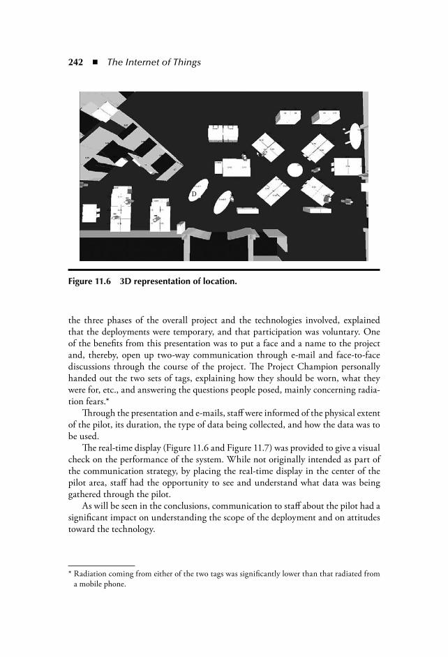
242 The Internet of Things
the three phases of the overall project and the technologies involved, explainedthat the deployments were temporary, and that participation was voluntary. Oneof the benefits from this presentation was to put a face and a name to the projectand, thereby, open up two-way communication through e-mail and face-to-facediscussions through the course of the project. The Project Champion personallyhanded out the two sets of tags, explaining how they should be worn, what theywere for, etc., and answering the questions people posed, mainly concerning radia-tion fears.*
Through the presentation and e-mails, staff were informed of the physical extentof the pilot, its duration, the type of data being collected, and how the data was tobe used.
The real-time display (Figure 11.6 and Figure 11.7) was provided to give a visualcheck on the performance of the system. While not originally intended as part ofthe communication strategy, by placing the real-time display in the center of thepilot area, staff had the opportunity to see and understand what data was beinggathered through the pilot.
As will be seen in the conclusions, communication to staff about the pilot had asignificant impact on understanding the scope of the deployment and on attitudestoward the technology.
* Radiation coming from either of the two tags was significantly lower than that radiated froma mobile phone.
D
Figure 11.6 3D representation of location.
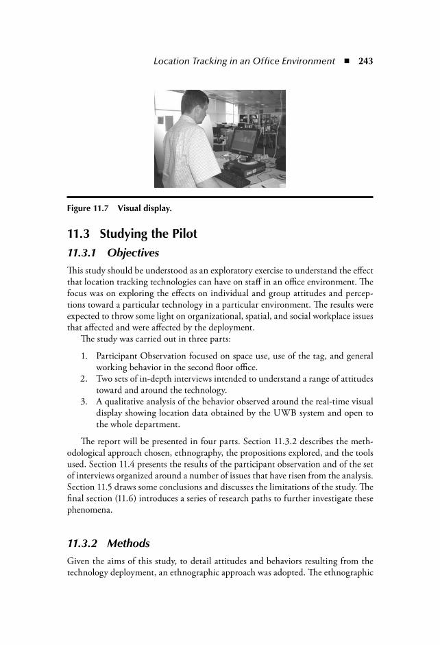
Location Tracking in an Office Environment 243
11.3 Studying the Pilot11.3.1 ObjectivesThis study should be understood as an exploratory exercise to understand the effectthat location tracking technologies can have on staff in an office environment. Thefocus was on exploring the effects on individual and group attitudes and percep-tions toward a particular technology in a particular environment. The results wereexpected to throw some light on organizational, spatial, and social workplace issuesthat affected and were affected by the deployment.
The study was carried out in three parts:
1. Participant Observation focused on space use, use of the tag, and generalworking behavior in the second floor office.
2. Two sets of in-depth interviews intended to understand a range of attitudestoward and around the technology.
3. A qualitative analysis of the behavior observed around the real-time visualdisplay showing location data obtained by the UWB system and open tothe whole department.
The report will be presented in four parts. Section 11.3.2 describes the meth-odological approach chosen, ethnography, the propositions explored, and the toolsused. Section 11.4 presents the results of the participant observation and of the setof interviews organized around a number of issues that have risen from the analysis.Section 11.5 draws some conclusions and discusses the limitations of the study. Thefinal section (11.6) introduces a series of research paths to further investigate thesephenomena.
11.3.2 MethodsGiven the aims of this study, to detail attitudes and behaviors resulting from thetechnology deployment, an ethnographic approach was adopted. The ethnographic
Figure 11.7 Visual display.
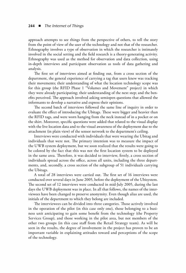
244 The Internet of Things
approach attempts to see things from the perspective of others, to tell the storyfrom the point of view of the user of the technology and not that of the researcher.Ethnography involves a type of observation in which the researcher is intimatelyinvolved in the social setting and the field research is a theory-generating activity.Ethnography was used as the method for observation and data collection, usingin-depth interviews and participant observation as tools of data gathering andanalysis.
The first set of interviews aimed at finding out, from a cross section of thedepartment, the general experience of carrying a tag that users knew was trackingtheir movements; their understanding of what the location technology scope was for this group (the RFID Phase 1 “Volumes and Movement” project) in whichthey were already participating; their understanding of the next step; and the ben-efits perceived. The approach involved asking semiopen questions that allowed theinformants to develop a narrative and express their opinions.
The second batch of interviews followed the same line of inquiry in order toevaluate the effect of introducing the Ubitags. These were bigger and heavier thanthe RFID tags, and were worn hanging from the neck instead of in a pocket or onthe shirt. Moreover, specific questions were added that related to the visual displaywith the live location data and to the visual awareness of the deployment due to theattachment (in plain view) of the sensor network to the department’s ceiling.
Interviews were conducted with individuals that were wearing the Ubitag andindividuals that were not. The primary intention was to measure the impact ofthe UWB system deployment, but we soon realized that the results were going tobe colored by the fact that this was not the first location system to be deployedin the same area. Therefore, it was decided to interview, firstly, a cross section ofindividuals spread across the office, across all units, including the three depart-ments, and, secondly, a cross section of the subgroup of 51 individuals carryingthe Ubitags.
A total of 28 interviews were carried out. The first set of 16 interviews wereconducted over several days in June 2005, before the deployment of the Ubisystem.The second set of 12 interviews were conducted in mid-July 2005, during the lastdays the UWB deployment was in place. In all that follows, the names of the inter-viewees have been changed to preserve anonymity. Even though alias are used, theinitials of the department to which they belong are included.
The interviewees can be divided into three categories. Those actively involvedin the operation of the pilot (in this case only one), those belonging to a busi-ness unit anticipating to gain some benefit from the technology (the PropertyServices Group), and those working in the pilot area, but not members of theother two groups (in this case staff from the Retail Strategy team). As will beseen in the results, the degree of involvement in the project has proven to be animportant variable in explaining attitudes toward and perceptions of the scopeof the technology.
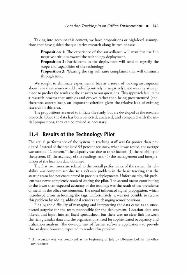
Location Tracking in an Office Environment 245
Taking into account this context, we have propositions or high-level assump-tions that have guided the qualitative research along its two phases:
Proposition 1: The experience of the surveillance will manifest itself innegative attitudes toward the technology deployment.Proposition 2: Participants in the deployment will tend to mystify thescope and capabilities of the technology.Proposition 3: Wearing the tag will raise complaints that will diminishthrough time.
We sought to eliminate experimental bias as a result of making assumptionsabout how these issues would evolve (positively or negatively), nor was any attemptmade to predict the results or the answers to our questions. This approach facilitatesa research process that unfolds and evolves rather than being prestructured (and,therefore, constrained), an important criterion given the relative lack of existingresearch in this area.
The propositions are used to initiate the study, but are developed as the researchproceeds. Once the data has been collected, analyzed, and compared with the ini-tial propositions, they can be revised as necessary.
11.4 Results of the Technology PilotThe actual performance of the system in tracking staff was far poorer than pre-dicted. Instead of the predicted 95 percent accuracy, when it was tested, the averagewas around 42 percent.* The disparity was due to three factors: (1) the reliability ofthe system, (2) the accuracy of the readings, and (3) the management and interpre-tation of the location data obtained.
The first two issues are related to the overall performance of the system. Its reli-ability was compromised due to a software problem in the basic tracking that thestartup team had not encountered in previous deployments. Unfortunately, this prob-lem was never completely resolved during the pilot. The second factor contributingto the lower than expected accuracy of the readings was the result of the prevalenceof metal in the office environment. The metal influenced signal propagation, whichintroduced errors in locating the tags. Unfortunately, it was not possible to resolvethis problem by adding additional sensors and changing sensor positions.
Finally, the difficulty of managing and interpreting the data came as an unex-pected surprise for the team responsible for the deployment. Location data wasfiltered and input into an Excel spreadsheet, but there was no clear link betweenthe rich granular data and the organization’s need for sophisticated occupancy andutilization analysis. The development of further software applications to providethis analysis, however, expected to resolve this problem.
* An accuracy test was conducted at the beginning of July by Ubisense Ltd. in the officeenvironment.
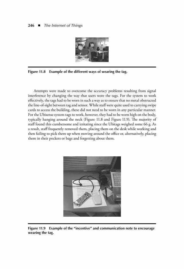
246 The Internet of Things
Attempts were made to overcome the accuracy problems resulting from signalinterference by changing the way that users wore the tags. For the system to workeffectively, the tags had to be worn in such a way as to ensure that no metal obstructedthe line-of-sight between tag and sensor. While staff were quite used to carrying swipecards to access the building, these did not need to be worn in any particular manner.For the Ubisense system tags to work, however, they had to be worn high on the body,typically hanging around the neck (Figure 11.8 and Figure 11.9). The majority ofstaff found this cumbersome and irritating since the Ubitags weighed some 66 g. Asa result, staff frequently removed them, placing them on the desk while working andthen failing to pick them up when moving around the office or, alternatively, placingthem in their pockets or bags and forgetting about them.
Figure 11.8 Example of the different ways of wearing the tag.
Figure 11.9 Example of the “incentive” and communication note to encourage wearing the tag.

Location Tracking in an Office Environment 247
One of the interviewees summarized user attitudes to the tags stating, “Themechanics of actually wearing it was inconvenient. Especially on top of the factthat we’ve also got another extra tag at the moment anyway. So we’re wander-ing around with three things around our necks where normally there’d be one.”(Mark PS).
Other staff commented that “I was pretty good about wearing it” (Anna RS), sug-gesting that wearing the tags never become “normal” and was viewed as an irritation.Clearly, the temporary nature of the deployment contributed to the willingness ofstaff to accept the inconvenience.
Despite this, after two weeks, scarcely anyone was wearing the tags as intended:hanging from the neck and in open view, facing the ceiling and clear of any obsta-cles. This, combined with the fact that the desks’ partitions were made out of metal,resulted in few as well as inaccurate readings.
To obtain better readings, attempts were made to change staff behavior in thethird week of the deployment. This proved difficult. The project champion wasable to make his staff wear the tags correctly for a few days, but, in the end, theywent back to wearing it in the way that best suited their habits. When it became anuisance, they simply dropped it. There were very few readings in the last days ofthe pilot as a result of this.
11.5 Results of the Study11.5.1 Understanding and CommunicationUser understanding of the pilot was largely a result of the communication strategy.Users held conflicting perceptions on the success of this strategy. A slight majorityof the staff believed that the communication strategy had been successful. “I actu-ally thought the communication was quite good and that it was communicatedclearly” (Gwen PS). On the other hand, a significant minority were critical, com-plaining about a lack of communication.
The informants’ understanding of the deployment in terms of objectives provedfairly good and there was a common agreement on the terms used to describeit: movement, space utilization, granular, granularity, workspace utilization, better working environment. This is a reflection of the internal communication campaignaccompanying the project that has helped to develop a shared understanding of thepilot aims. Understanding was not, however, uniform. “It is difficult to know whatyou are trying to get out of the project” (Anna RS).
Despite the efforts put into communication, staff failed to understand the proj-ect scope and physical extent of the pilot. None of the respondents, apart fromindividuals working very closely on the deployment, could explain the scope of thetracking: in which areas it was happening and in which it was not. When askedabout boundaries, a typical response was: “I have got no idea. I don’t know what

248 The Internet of Things
area is actually being measured” (Shaun PS). And this despite the fact the sen-sor network was hanging from the ceiling in open view with the sensor boxespointing inwards.
Users generally did not understand the purpose of the data and they did notunderstand how the raw data was being used to analyze space utilization. Althoughthe communication process was used to diffuse concerns about data protection,this aspect of the pilot was not covered in the communication plan. As we observein section 11.5.3 on privacy, misconceptions about the way data was being used didlead to concerns among staff.
11.5.2 The Temporary Nature of the DeploymentAcceptance of the deployment was significantly eased by the fact that the deploy-ment was just a trial and was temporary in nature. “I had no real problem with it.I understand this was just a trial, wasn’t it?” (Carol RS). The fact that the deploy-ment was temporary meant that it was not perceived as genuine. “So, you know, ifyou did it for real”(Robert PS). This fact hugely influences concerns about privacyand other attitudes toward the technology.
11.5.3 Privacy and IntrusionThe real-time display in the center of the pilot area provided an element of opennessregarding the data being collected by the system, allowing the staff to see exactlywhat data was being gathered. Staff did, however, have some concerns about pri-vacy, despite the communication plan and the real-time display.
Participants reacted to the display in two ways, one set of respondents lookedat it, found it interesting and looked for themselves, but could not make out wherethey were and if they were moving, and, therefore, lost interest. This group alsofound it open, a feature that showed there was “nothing to hide” (Gwen PS). Theother set did not look at it, lacked interest in it, and had a general feeling that it was“a PR exercise” (Matthew RS).
Staff concerns about privacy appear to be strongly influenced by their perceptions ofthe system’s capabilities and operation. Despite the efforts put into communication, themajority of the beliefs of staff regarding the system were at variance with the reality.
With regard to privacy, there is a difference between location data being gath-ered by a system and the system providing the capability to extract informationabout individual’s behavior. The Ubisense system did not provide this secondcapability, but staff did have concerns about their privacy being invaded by beingobserved all of the time at work.
There was a high degree of uniformity among participants in their misunder-standing of this aspect of the pilot. None of the respondents, apart from thoseworking very closely on the deployment, could even explain the scope of the track-ing, in which areas it was happening, and in which it was not.

Location Tracking in an Office Environment 249
The uniformity of staff perceptions regarding how they were being trackedcould be understood using the concept of “collective imaginaries”* built by theinformants around the technology deployment. As a result of the experience of thedeployment, informants developed a thought structure that combined rumor andreason that resulted in the mystification of the spatial and technical scope of thetechnology and the manipulation of the location data obtained.
These collective imaginaries are constructed within social groups exposed to thesame experience and information and takes the form of a shared belief. Discussionsand conversations between group members may serve only to strengthen and entrenchthis shared impression. With regard to the staff at Nationwide, a majority thoughtthat they were being tracked around the whole building, into the toilets, and that“someone” was able to know exactly what they were doing at all times and with whom.It is plausible that the collective imaginaries that developed were influenced by thenational context, with considerable media attention devoted to debates on identitycards, CCTV, and, perhaps in part, by reality TV shows, such as Big Brother. Theshared organizational context and culture also is likely to have had an influence.
Again, it should be observed that not all staff shared the collective belief regard-ing the extent to which the system was being used to monitor individual behavior.However, it may be pertinent to note that the only staff member explicitly to rejectthis concern (stating, “It’s not being used to track you around the building” (LauraPS), worked in the Property Services group with a responsibility for security.
11.5.4 Attitudes and Organizational CultureAs noted earlier, Nationwide places considerable emphasis on the creation of acommon organizational culture. This is reflected in the strong branding aroundthe building. Large numbers of images and messages are displayed proclaiming theorganizations values, the degree to which they care about their staff, advertising theexhibits they organize every week, the superb canteen, the Starbucks coffee, etc.
The interview responses support the fact that there is a strong organizational cul-ture and suggest that it had a positive impact on staff attitudes to the deployment.
Key aspects of the influence of the culture relate to trust and to pride in theorganization. The general perception that Nationwide is a fair and open organizationappears to have been transferred into attitudes to the deployment. Staff explicitly
* The concept of collective imaginary refers to the body of symbolic landmarks through whichany collectivity inserts itself in time and space. This process involves the establishment of fourrelationships:
A relationship to space, resulting in a territoriality. A relationship to Self and to Others, giving shape to an identity. A relationship to the past, which is expressed in a collective memory.
A relationship to the future, which is expressed in utopias: http://www.uqac.ca/_bouchard/chaire_desc_e.html.

250 The Internet of Things
cited their trust in the organization to explain their lack of concern of the potentialfor the technology to be used to monitor them. Responses to questions about theuse of the data from the pilot, such as “No, I think Nationwide is a fair organiza-tion” (Andrew PS), were typical.
Responses also suggest pride in being part of an advanced, forward-thinkingcompany. The deployment of an advanced technology could be seen to fit withstaff perceptions about their organization and in itself become a focus for pridein the company. “There doesn’t seem to be anybody else sort of doing this work…this kind of smart work environment that we’ve got here because we’re kind ofthe first department to have this environment” (Shaun PS), and “Nationwide setsthemselves as a, you know, benchmark for other people, to come in and have a lookat what we’re doing. So we’re at the forefront, which is good” (Albert PS).
While a strong organizational culture exists in Nationwide, it would be wrongto depict it as all pervading or perhaps totalitarian. The organizational culture isfor most, if not all staff, only one of a number of cultures within which they areimmersed. Their response and commitment to the organizational culture is medi-ated by the influence of national, local, religious, and, potentially, class cultures.
Underneath the widespread acceptance of the organizational values and ethos,however, a current of cynicism was apparent, suggesting that the overt organiza-tional culture, while powerful, is not ubiquitous. Surreptitious reluctance and evenbitterness for making participation in the project ostensibly voluntary while mak-ing it clear that those who did not take part were acting against the organizationalmodus operandi, ran strongly in some interviews.
Dissention from the accepted ethos was, however, rarely explicitly stated, ratherbeing conveyed through tone of voice, expression, and body language. Clearly noorganization such as Nationwide can ever maintain nor, in all likelihood, wouldit seek to maintain, an all pervading influence on the views and perceptions ofindividual staff.
11.6 Conclusions11.6.1 Conclusions Regarding the PilotThe results of the pilot were mixed. Installation was more time consuming andintrusive than anticipated and the system never delivered the promised degree ofaccuracy.
These problems were caused by two related issues.
1. The pervasive presence of metal in the environment interfered with thetransmission of the signals.
2. Users’ preferences on how tags were actually worn and carried conflictedwith the operational requirements of the system.
Location Tracking in an Office Environment 251
Metal partitioning is extremely common in office environments and its presenceshould have been foreseen. Developing technologies away from the real world con-text in which they will be deployed is likely to result in these kinds of problems.
Users’ habits and ingrained behaviors are extremely hard to change. Technolo-gies that require these changes are unlikely to succeed, in the absence of a strongsense of perceived benefit. However, the data gathered by the system can provideclear insights into how buildings are actually used through time and offers realpotential for improving our understanding of human behavior in office environ-ments. If these potential benefits are to be realized, more sophisticated applicationswill be required to translate the raw XYZ data into useful information.
Studying the deployment of a location system in an office environment hasbrought to light the “perfect system versus degraded environment dilemma”. Thereis a fundamental difference, and different results too, between setting up a tech-nology experiment in a controlled environment and taking it into real life. As wehave observed, real environments are complex and unstable for a combination ofspatial and social reasons, among others. The majority of computer scientists tendto think about “perfect systems” that work very well in a “perfect environment”in which those two variables are controlled. When faced with a real environment,this is perceived as degraded because it does not provide the same controlled andperfect space. In this case, the technology provider had made assumptions, giventhe performance of the system in controlled environments they knew well, such astheir own office in Cambridge, that do not apply to all buildings or organizations.Consequently, expectation mismatches and disappointment can follow the deploy-ment of technology.
It is our contention, as a result of the experiments conducted at Nationwide,that this approach is naive. Real deployments, and, in particular, the engagementof real stakeholders, should become requirements of the test environment in whichthe claims made for such systems are validated.
11.6.2 Conclusions Regarding the Study of the PilotGiven the efforts put into communicating to staff, it is perhaps surprising to dis-cover how poorly the staff understood the pilot. This lack of understanding wasnot, however, uniform. Unsurprisingly, perhaps, those most closely involved hadthe most accurate understanding. Perhaps more significantly, staff from PropertyServices, who had direct involvement in the pilot, generally had a better under-standing of its objectives, scope, and extent. This may be due to closer informalcontact with staff who were directly involved and, hence, had a better under-standing. It also may be due, in part, to the fact that it was widely understoodthat this pilot would benefit their group, even if the nature of the benefit waspoorly understood.
252 The Internet of Things
The relative failure of the communication strategy can be explained by a numberof factors. While presentations were given to staff and information was transmittedthrough e-mails and other means, these communications were competing for thelimited attention busy staff have with other communications directly relating totheir jobs and roles. In the face of this competition, staff with no attachment tothe pilot simply do not appear to have taken the time to read and understand thecommunications sent to them.
A recommendation would be to have more face-to-face communication, infor-mal talks, and information sessions, in small groups with a proactive approach, inorder to obtain the engagement of the participants. In the case reported here, only1 out of 15 interviewees was present at the presentation given at the beginning ofthe project.
Lack of attachment or sense of involvement can largely be explained by the factthat the system provided no tangible benefits to staff outside the Property Servicesgroup. The ability of these systems to offer tangible benefits to all users is likelyto be an important factor in staff’s understanding and ultimately acceptance ofthe location tracking systems. A successful invasive office technology must providetangible and immediate benefits to the workers involved. That holds for all types ofsystems, whether collaborative or not, synchronous or asynchronous.
Thus, the deployment of a location tracking system in an office environmentshould provide a set of benefits and such benefits are usually perceived throughfunctionalities of a system and their direct impact on the personal working experi-ence of an individual. In this pilot only one such direct functionality existed—thestand alone computer acting as a 3D visual display of the real-time tracking move-ments. Nobody saw this as a benefit.
Belonging is an influential variable on the perception of benefits. Moreover,given the personal sensitivities involved, good communication is key to under-standing the data obtained and allowing for its effective interpretation andmanipulation.
Recommendations for the design of a deployment should take into accountthese findings and adopt a multilevel deployment strategy involving at a minimumthe social, spatial, technological, and temporal issues discussed within this chapter.Issues of privacy, transparency, and control are influenced by collective imaginariesthat mystify the technology and increase fears of privacy invasion, lack of transpar-ency over the data, and losing control over the manipulation and post processingof the data. The influence diminishes, and, therefore, objective understanding ofthe deployment improves if one is involved in the project and trust in the organiza-tion is solid. It would be a mistake, however, to assume that, outside the protectiveenvironment afforded by the company, one would see the same reactions to privacy-invading measures of the individuals involved.

Location Tracking in an Office Environment 253
11.6.3 Conclusions Regarding the Approach to the Study of the Pilot
The choice of an exploratory research approach and of ethnography as our fieldworkapproach can be criticized. Critics point out the nongeneralizable nature of thisapproach, the fact that is not “representative, and therefore we cannot conclude thatcharacteristics of the sample will be found in the larger population”. We argue thatany findings generated by this kind of research should be regarded as a steppingstone to future studies, exactly as we intended.
The third issue is linked to the choice of ethnography as a fieldwork approach.Critiques highlight its journalistic, unscientific, descriptive, nonanalytical, andsubjective nature. We say that it is a style of research that is committed to studyingpeople’s understandings, meanings, and practices, and that fits very well with ourresearch propositions. Our primary intent was to give voice to people’s reactionsand understanding of the technology.
For this particular case, an exploratory approach was necessary because of thelack of similar previous research in the field. It proved to be a choice that, coupledwith an ethnographic approach, provided a fruitful approach to the study of perva-sive technologies in the office environment.
11.7 Open IssuesThe richness of the raw data is barely harnessed by the applications in the currentsystem. There is a challenge for software developers in partnership with workplacedesigners, facilities management specialists, and social scientists to create furtherapplications that can exploit the richness of this data.
These applications could include applications for social/spatial data miningwith improved visualizations of these relationships.
A further research challenge is for social scientists and technologists to takeexisting theories on how technology deployment is influenced by social issues anddevelop them to include the spatial dimension.
The information derived from these location tracking technologies has con-siderable potential to inform workplace design. This presents a challenge to work-place design professionals to develop evidence-based approaches to workplacedesign.
The ultimate challenge would be for technology developers to use the insightsfrom social scientists regarding the user responses to the deployment within theirapproach to technology development. The suggestion is that a more user-centereddevelopment approach, combined with early pilots in real environments, could leadto technologies more likely to gain user acceptance.

254 The Internet of Things
AcknowledgmentsThe authors would like to acknowledge the financial support provided by the EC-funded RUNES project, and to express our sincere appreciation to the Nationwidebuilding society and, in particular, Fred J. Child, for allowing us to conduct thisstudy. Child, Pete Steggles, and David Theriault, from Ubisense Ltd., have read thischapter and provided comments. We would further like to thank Paul Wheeler fromLand Securities Trillium for constructive discussions over the course of the study.
BibliographyAipperspach, R. et al., Maps of our lives: Sensing people and objects together in the home,
Electrical Engineering and Computer Sciences University of California at Berkeley,Technical report No. UCB/EECS-2005-22, November 30, 2005.
Anderson, B., Imagined Communities. Verso, London, 1991.Appadurai, A., Modernity at Large. University of Minnesota Press, Minneapolis, 1996.Babbie, E., The Practice of Social Research, 10th ed. Thomson Wadsworth, Belmont, CA, 2004.Barney, J.B., Fuerst, B., and Mata, F., Information technology and sustained competitive
advantage: A resource-based analysis, MIS Quarterly, 19, 1996, pp. 487–505.Barney, J.B., The resource-based theory of the firm, Organization Science, 7, 5, 1996, pp. 469.Castoriadis, C., The Imaginary Institution of Society. MIT University Press, Cambridge,
MA 1987.Child, F.J., Capacity Management Pilot Project for “Proof of Concept:” Business Require-
ments, Nationwide Internal document, February 2005.Child, F.J., RFID Pilot Project Update to A2 teams, Nationwide Internal document, May
2005.Harrison, A. and Steggles, P., Evaluation of an AmI workplace, in the Proceedings of
e-Challenge 2004 International Conference, Vienna, Austria, October 2004.Hatch, M.J., Organization Theory: Modern Symbolic and Postmodern Perspectives, Oxford
University Press, Oxford, U.K., 1997.Hillier, B. and Hanson, J., The Social Logic of Space, Cambridge University Press, London,
1989.Hillier, B., Space Is the Machine, Cambridge University Press, London 1996.Lopez de Vallejo, I. et al., Ambient intelligence in manufacturing: organizational impli-
cations. Workshop on Ubiquitous Computing and Effects on Social Issues’ CHI05,Portland, OR, April 2005.
Lopez de Vallejo, I., Ambient intelligence vision: Exploring the social risks of its con-struction. In The Proceedings of e-Challenges 2004 International Conference, Vienna,Austria. October 2004.
Lopez de Vallejo, I., Soft factors in the new ICT-powered workspace. In The Proceedings of e-Challenges 2003 International Conference, Bologna, Italy, October 2003.
Mannings, R., Whereness: Ubiquitous positioning, Journal of the Communication Network,4, I, January–March 2005.
Mills, C.W., The Sociological Imagination, Oxford University Press, New York, 1959.Norman, D.A., The Invisible Computing, MIT Press, Cambridge, MA, 1998.
Location Tracking in an Office Environment 255
Orlikowski, W., The duality of technology: Rethinking the concept of technology inorganizations, Organization Science, 3, 3, Focused Issue: Management of Technology,August 1992, p. 405.
Parliamentary Office of Science and Technology, POST note 263, Pervasive Computing,London, May 2006.
Penn, A., Space for innovation: effects of spatial configuration on social and knowledgegeneration. In Proceedings of the First Workshop for Cooperation between Japan and the United Kingdom on SOFT Science and Technology, 126-8 and 172-6, November 1994,STA, Osaka, Japan.
Penn, A., Desyllas, J., and Vaughan, L., The space of innovation: Interaction and com-munication in the work environment, Environment and Planning B: Planning and Design, 1999, vol. 26, 193–218, Pion Publishing, London.
Seale, C., Social Research Methods: A Reader, Routledge, New York, 2003.Spiliopoulou, G., and Penn, A., Organisations as multi-layer networks: face to face, email and
telephone interaction in the workplace. In the Proceedings of the Second International Space Syntax Symposium, March 1999, Brasilia, Bartlett, UCL, London, 1999, vol. 1, p. 13.
Spradley, J., and McCurdy, D., The Cultural Experience, Waveland Press, Prospect Heights,IL, 1972.
Spradley, James P., ed. Participant Observation, Holt, Rinehart and Winston, New York,1979.
Spradley, James P., ed. The Ethnographic Interview, Holt, Rinehart and Winston, New York,1980.
Steggles, P. and Cadman, J., A Comparison of RF Tag Location Products for Real WorldApplications: A Ubisense White Paper, Ubisense, Cambridge, U.K., March 2004.
Taylor, C., Modern Social Imaginaries. Duke University Press, Durham, VC, 2004.Ubisense Web site: http://www.ubisense.netUbisense, Ltd., Summary Report on Evaluation Trial at Nationwide, June 2005, prepared for
Nationwide Ltd., Nationwide Internal document, 27 July 2005. (www.ubisense.com).Ward, A., Webster, P., and Batty, P., Local Positioning Systems: Technology Overview and
Applications, Ubisense, Cambridge, U.K., September 2003.Ward, A. and Cadman, J., Deploying commercial location aware systems, UbiComp 2003,
Seattle, WA, October 2003.Weiser, M ,The computer of the 21st century, Scientific American, September 1991.Weiser, M., Some computer science issues in ubiquitous computing, Communications of the
ACM, July 1993.Weiser, M. and Seely Brown, J., The technologist’s responsibilities and social change,
Computer Mediated Communication Magazine, 2, 4, April 1995.Weiser, M. and Seely Brown, J., The coming age of calm technology, PowerGrid Journal,
v. 1.01, http://powergrid.electricit.com/1.01 (July 1996).

257
Chapter 12
Pervasive Computing Security: BluetoothExample
Giorgos Kostopoulos, Paris Kitsos, and Odysseas Koufopavlou
Contents12.1 Introduction ...........................................................................................25812.2 Bluetooth Security Layer Specification Description...............................260
12.2.1 Key Management .......................................................................26112.2.2 Authentication ...........................................................................26212.2.3 Encryption .................................................................................263
12.3 Bluetooth Security Layer Architectures and Implementations ...............26412.4 Hardware Implementation of the Bluetooth Security
Specifications .....................................................................................26412.4.1 SAFER Block Cipher Hardware Architecture ..........................26512.4.2 The Link Key Generation Function E2.......................................26712.4.3 The E1/E3 Function Architecture.............................................26812.4.4 The E0 Unit Architecture.........................................................268

258 The Internet of Things
12.1 IntroductionThe proliferation of wireless handheld devices and advances in network technolo-gies, and the desire to stay connected anytime and anywhere, has ushered in thedomain of mobile and pervasive computing. Wireless mobile phones that also serveas personal digital assistants (PDAs) will become the norm in everyday life. Peoplecarrying these devices will be surrounded by intelligent and networked devices andembedded computing appliances, e.g., at home and work, in our cars, in publicspaces, etc. The fact that we can use them everywhere drastically changes the waywe use computers and imposes new requirements on computing and communica-tions as well in applications, in general.
Mobile computing targets the mobility of users, data and systems, informationorganizations, and access methods for data services and management in mobile sys-tems. Pervasive computing builds on mobile computing techniques and concernsthe creation of environments populated with human beings, wireless networkingdevices, and physical objects that satisfy the properties of physical integration andinstantaneous interoperation. In pervasive computing, the actual terminals can behidden from the user or can be disguised as something else (like a coffee cup). Perva-sive seems to imply also some kind of distribution of computation (i.e., “chip rich”environments) among different devices. Bluetooth [1] is a technology and stan-dard that is designed as a wireless cable replacement, which connects a wide rangeof devices. In contrast to wireless LANs, (local area networks) such as 802.11b, it
12.5 Bluetooth Enhanced Security Layer (ESL) Hardware Implementation....27012.5.1 Enhanced Security Layer (ESL) .................................................27112.5.2 Enhanced Security Design .........................................................27212.5.3 ESL Entities ...............................................................................27412.5.4 Prototype Architecture...............................................................27512.5.5 Security Processing Hardware....................................................27612.5.6 Communication.........................................................................27812.5.7 Software Interfaces.....................................................................279
12.6 Bluetooth Security Implementation Based on Software-OrientedHardware–Software Partition .............................................................28012.6.1 Constructing Block Ciphering Functions in Software...............28012.6.2 Timing Analysis of Block Ciphering Functions..........................28112.6.3 Timing Constraint of Block Ciphering Functions......................28112.6.4 Timing Measurement of Block Ciphering Functions
in Embedded MCU....................................................................28212.6.5 Constructing and Analysis of Stream Ciphering Function.........28212.6.6 Implementation Results .............................................................283
12.7 Conclusion ........................................................................................284References .........................................................................................................285
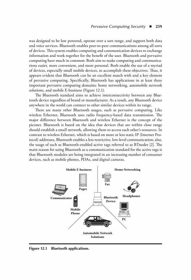
Pervasive Computing Security 259
was designed to be low powered, operate over a sort range, and support both dataand voice services. Bluetooth enables peer-to-peer communications among all sortsof devices. This system enables computing and communication devices to exchangeinformation and work together for the benefit of the user. Bluetooth and pervasivecomputing have much in common: Both aim to make computing and communica-tions easier, more convenient, and more personal. Both enable the use of a myriadof devices, especially small mobile devices, to accomplish these objectives. Thus, itappears evident that Bluetooth can be an excellent match with and a key elementof pervasive computing. Specifically, Bluetooth has applications in at least threeimportant pervasive computing domains: home networking, automobile networksolutions, and mobile E-business (Figure 12.1).
The Bluetooth standard aims to achieve interconnectivity between any Blue-tooth device regardless of brand or manufacturer. As a result, any Bluetooth deviceanywhere in the world can connect to other similar devices within its range.
There are many other Bluetooth usages, such as pervasive computing. Likewireless Ethernet, Bluetooth uses radio frequency-based data transmission. Themajor difference between Bluetooth and wireless Ethernet is the concept of thepiconet. Bluetooth is based on the idea that devices that are within close rangeshould establish a small network, allowing them to access each other’s resources. Incontrast to wireless Ethernet, which is based on more or less static IP (Internet Pro-tocol) addresses, Bluetooth enables a less restrictive, low-level communication; also,the usage of such as Bluetooth-enabled active tags referred to as BTnodes [2]. Themain reason for using Bluetooth as a communication standard for the active tags isthat Bluetooth modules are being integrated in an increasing number of consumerdevices, such as mobile phones, PDAs, and digital cameras.
Mobile E–business
Pager
Communicator
Mobile
Phone
Automobile Network
Solutions
Bluetooth
Device
PC
Headphones
Fax
Home Networking
Figure 12.1 Bluetooth applications.
260 The Internet of Things
This system enables computing and communications devices to exchange infor-mation and to work together for the benefit of the user. Bluetooth operates in the2.45 GHz ISM (Industrial, Scientific, Medical) band and can be used all over theworld. The communications between Bluetooth devices will hop between 1,600different frequencies per second across a total of 79 frequencies, moving in a quasi-random fashion. Air interface traffic will also be encrypted using a key between 8and 128 bits. Applications using Bluetooth can provide their own encryption layer.This multilayered approach considerably reduces the possibility of undetected andundesirable intrusion [3].
The operating system designers and the computers’ administrators had to thinkof ways to restrict users from reading confidential data, destroying data that didnot belong to them, and doing countless other acts, which could compromise thesecurity of the system. Networking created new problems: eavesdropping on trans-mitted data and malicious computers on the networks. As corporations began touse the networks, more and more financially important data was being transferred.Portable handheld and embedded devices have severely limited processing power,memory capacities, software support, and bandwidth characteristics. Also, hard-ware and software environments are becoming increasingly heterogeneous, a trendthat will continue in the foreseeable future. Finally, security information in differ-ent domains is subject to inconsistent interpretations in such an open, distributedenvironment.
12.2 Bluetooth Security Layer Specification Description
Bluetooth includes security features at the link level. It supports authentication,encryption, and key management. These features are based on a secret link key thatis shared by a pair of devices. To generate this key, a pairing procedure is used whenthe two devices communicate for the first time.
The link level functions are defined in the Bluetooth Baseband and the LinkManager Protocol (LMP) Specifications. The generic access profile specifies threesecurity modes for a device. In security mode 1, the nonsecure mode, a device willnot initiate any security procedure. In security mode 2, the service level-enforcedsecurity mode, a device does not initiate security procedures before channel estab-lishment at the L2CAP level. This mode allows flexible access policies for applica-tions, especially when applications with different security requirements are run inparallel. In security mode 3, the link level-enforced security mode, a device initiatessecurity procedures before the link setup at the LMP level is completed. Accordingto the Bluetooth security level for the device, security level 1 uses untrusted devicesand level 2 uses trusted devices only. As the Bluetooth security level for service,security level 1 requires authorization and authentication, security level 2 requiresauthentication only, and level 3 opens all devices [1].

Pervasive Computing Security 261
Bluetooth layer security uses four key elements: a Bluetooth device address, twoseparate key types (authentication and encryption), and a random number. Theauthentication key generates the encryption key during the authentication phase. Arandom or pseudo-random process is used in order to produce the random number.The security layer includes key management, generating key mechanisms, user anddevice authentication, and data encryption. The Bluetooth security architecturecan secure all the upper layers by enforcing the Bluetooth security policy, or it canbe flexible enough to let those layers use their own security policies.
12.2.1 Key ManagementWhen a connection starts, the parties need to enter their personal identificationnumbers (PINs) (Figure 12.2). By using this PIN, the link key generation function(E2) generates the appropriate link key. This key is used by the authentication func-tion (E1) in order to authenticate the identity of the connection parties. In case thatdata encryption is required, the encryption key generation function (E3) producesthe encryption key by using the same link key. The encryption key is used by theE0 encryption function in order to encrypt or decrypt the sending or the receivingdata.
During a connection several different types of 128-bit link keys are produced.These keys handle all security transactions between two or more parties. Dependingon the type of application, the link keys can be initialization or unit, or combinationor master keys. The lifetime of a link key depends on whether it is a semipermanent
PIN
Link key
generation (E2)
Encryption keygeneration (E3)
link key
EncryptionKey
PIN
Link key
generation (E2)
Encryption keygeneration (E3)
link key
EncryptionKey
Authentication
E1
Encryption
E0
Figure 12.2 Key generation process.

262 The Internet of Things
or a temporary key. In a point-to-multipoint connection, where the same informa-tion is transmitted to several recipients, a master (temporary) key is used. All theother types of link keys are semipermanent. In addition to the link keys, there is theencryption key. The encryption key generation process uses the current link key inorder to produce the encryption key.
In the initialization connection phase between two parties, each party producesits own initialization key K INIT. This key is generated by the key generation func-tion (E22). The input parameters of the E22 are the PIN code, the Bluetooth deviceaddress, and a 128-bit random number. The initialization key KINIT is used in orderto produce the next link keys.
The two parties decide which link key (combination or unit key) will produce.In case a device has limited memory, it chooses to produce a unit key. In this case,the device does not need to remember different keys for different links. The keygeneration function (E21) generates the unit key. The input parameters of the E21
are the KINIT, the Bluetooth device address, and a 128-bit random number. The twoparties may also decide to use the combination key. In this case, in both devices,the key generation function E21 generates temporary keys. These keys are exchangedbetween the two devices and are used in order to produce the combination keys.
When a master device broadcasts data to several slave devices, it uses the masterkey. The master device generates the master key in the key generation function E22
by using two 128-bit random numbers. Then, the master device sends to all theslave devices a random number. In all the devices (master and slaves), the genera-tion function (E22) uses this random number and the current link key in order toproduce the overlay (OVL) number. Then, the master device sends to all the slavesthe master key bitwise XORed with the overlay. So, each slave can calculate themaster key.
12.2.2 AuthenticationThe Bluetooth authentication uses a challenge-response scheme where it is used tocheck whether the other party knows the link key. Authentication is accomplishedby using the current link key. The process is symmetric, so a successful authentica-tion is based on the fact that both parties share the same key.
First, the verifier (master) sends to the claimant (slave) a random number A(Figure 12.3). Then, both parties use the authentication function (E1), with inputof the random number A, the claimants’ address (Bluetooth device address B), andthe current link key in order to produce the signed response (SRES). Number Ldenotes the length of the actual current link key. After this, the claimant sends theSRES to the verifier. Finally, the verifier checks the matching of the two SRESs.
The verifier may not necessarily be the master. Some of the applications requireonly one-way authentication. In both parties, E1 computes and stores the authenti-cated ciphering offset (ACO), which is used for the encryption key generation.

Pervasive Computing Security 263
12.2.3 EncryptionWhen the Link Manager activates the encryption, the encryption key is generated.The key generation function (E3) generates the encryption key Kc, from the currentlink key, a 96-bit ciphering offset number (COF) and a 128-bit random number.TheCOF is based on the ACO, which is generated during the authentication pro-cess. The encryption key size varies from 8 to 128 bit. In a Bluetooth system, onlythe payload of the packet is encrypted. This is achieved by using the stream cipherfunction (E0). The input of the E0 are the encryption key Kc, the Bluetooth deviceaddress A, and some data of the master real-time clock (Figure 12.4). E0 consists ofthe payload key generator, the key stream generator, and the encryption/decryptionpart [1].
The payload key generator combines the E0 input bits in an appropriate orderand leads them to the four linear feedback shift registers (LSFR) of the key streamgenerator [4]. Different encryption modes are used depending on the party link keytype. The broadcast traffic is not encrypted in the case that a combination or unit
Master Slave
RandomNumber A
Data
master clockdata
master clockdata
Bluetooth deviceaddress A
Bluetooth deviceaddress A
encryption key Kc encryption key Kc
Kstream Kstream
Data A––>B
Data B– –>A
Data A––>B
Data B– –>A
E0 E0
Figure 12.4 Encryption process.
Master Slave
SRES
randomnumber A
randomnumber A
Bluetooth deviceaddress B
link key
L
randomnumber A
Bluetooth deviceaddress B
link key
L
ACO ACO?SRES' = SRES SRES
E1 E1
Figure 12.3 Authentication process.
264 The Internet of Things
key is used. If a master key is used, there are three possible encryption modes. Inencryption mode 1, nothing is encrypted. In encryption mode 2, broadcast trafficis not encrypted, but the individually addressed traffic is encrypted with the masterkey. Finally, in encryption mode 3, all traffic is encrypted with the master key.
12.3 Bluetooth Security Layer Architectures and Implementations
Until now there are many designing approaches for Bluetooth depending on thekind of the application. For example, some companies (e.g., Philips, Ericsson,Zeevo) have been integrating the basic Bluetooth baseband functions in hardware.Other companies, like Oki Semiconductor and Intel, provide an HCI (host con-trol interface) that can be controlled, for example, across a USB (Universal SerialBus) interface. In [5], an analytical description of the hardware architecture andimplementation of the Bluetooth security is analyzed, dictated by the official speci-fications. Also, in [6] an implementation of a new enhanced security layer (ESL)is presented. The security level is increased by replacing the encryption with AES(Advanced Encryption Standard) and adding integrity protection. The securityprocessing is implemented in hardware for high performance. Finally, in [7] a par-titioning hardware and software implementation is introduced. Also, the resource-sharing scheme is adopted. The partitioning and resource-sharing reduce hardwareresources though the timing requirement is fulfilled.
12.4 Hardware Implementation of the Bluetooth Security Specifications
The proposed system architecture for the Bluetooth security hardware implementa-tion is depicted in Figure 12.5. It consists of six units: (1) E2 link key generationfunction, (2) E1/E3 function, (3) RAM/ROM memories, (4) E0 stream cipher func-tion, (5) control, and (6) I/O (input/output) Interface.
The E2 link key generation function unit produces the appropriate link keys. Byusing these link keys, the E1/E3 function unit performs the authentication and pro-duces the encryption key. For data encryption, the E0 stream cipher function unitis used. All the interunit data movements are being transferred through the 64-bitdata bus. RAM memory has also been integrated in order to store the appropriatefunction keys. All the function constants are stored in the ROM memory. Thecontrol unit synchronizes the operation of the system. The system communicateswith the external environment through the I/O interface. The basic component ofall the key generation functions (E2, E3) and authentication function (E1) is theSAFER block cipher [1].

Pervasive Computing Security 265
12.4.1 SAFER Block Cipher Hardware ArchitectureThe hardware implementation of the SAFER block cipher is illustrated inFigure 12.6. It consists of two main units: the encryption data path and the key-scheduling unit. The key-scheduling unit allows an on-the-fly computation of theround keys. In order to reduce the covered area, eight loops of a key scheduling,single round implementation is used. The bias vectors are implemented by using17 16-byte ROM blocks.
Round keys are applied in parallel in the encryption data path. For the fullSAFER algorithm execution, eight loops of the single round are needed. The sin-gle round hardware implementation solution was chosen because, with this mini-mum resource covered area, the required throughput can be achieved.
The first component of the encryption data path is an Input register, whichconcatenates the Plaintext and the Feedback data produced in the previous round.The input register feeds the SAFER single round. After the SAFER single roundin the encryption data path is a mixed addition/XOR component, which combinesthe feedback data with round subkey K17. The final stage of the encryption datapath is the Output register.
The four subunits of a SAFER single round (Figure 12.7) are:
1. The mixed XOR/addition subunit, which combines data with appropriateround subkey K2r 1.
E2 Link key generation
function unit
E0 Stream cipher
function unit
RAM
ROM
E1/E3 Function
unit
Control
unit
I/O
interface
Da
ta B
us
Figure 12.5 Bluetooth security system architecture.
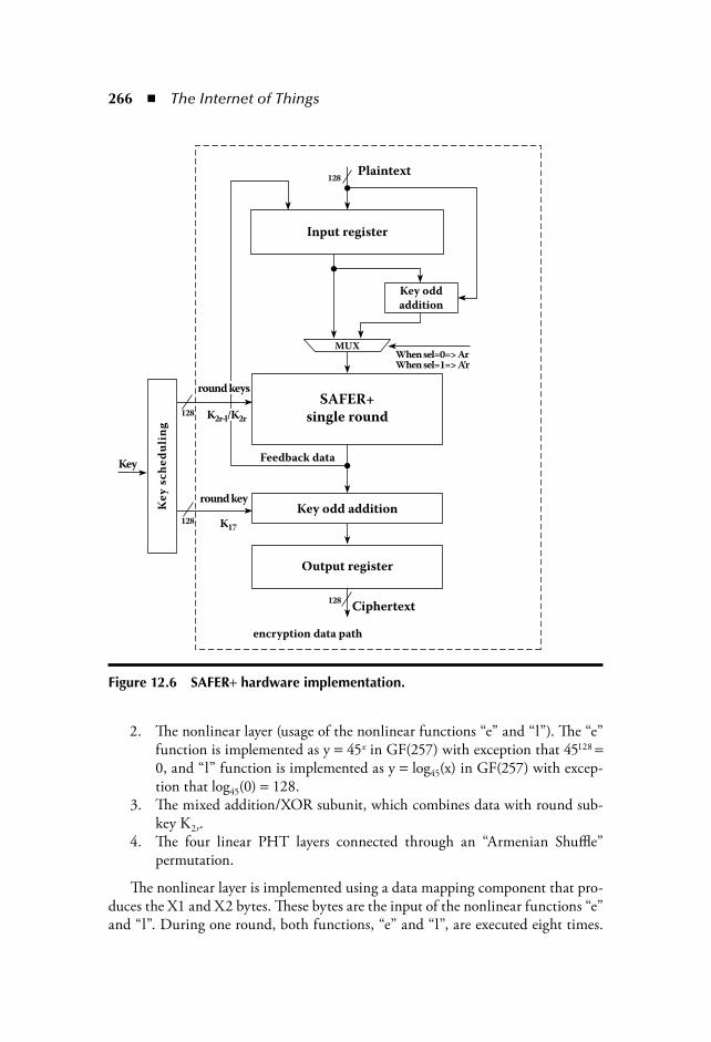
266 The Internet of Things
2. The nonlinear layer (usage of the nonlinear functions “e” and “l”). The “e”function is implemented as y 45x in GF(257) with exception that 45128
0, and “l” function is implemented as y log45(x) in GF(257) with excep-tion that log45(0) 128.
3. The mixed addition/XOR subunit, which combines data with round sub-key K2r.
4. The four linear PHT layers connected through an “Armenian Shuffle”permutation.
The nonlinear layer is implemented using a data mapping component that pro-duces the X1 and X2 bytes. These bytes are the input of the nonlinear functions “e”and “l”. During one round, both functions, “e” and “l”, are executed eight times.
Feedback data
round keys
round key
Ke
y s
ch
ed
uli
ng
encryption data path
Ciphertext
Output register
Key odd addition
Key odd
addition
When sel=0=> ArWhen sel=1=> A'r
Input register
Plaintext
MUX
Key
K2r–l/K2r
K17
SAFER+single round128
128
128
128
Figure 12.6 SAFER hardware implementation.
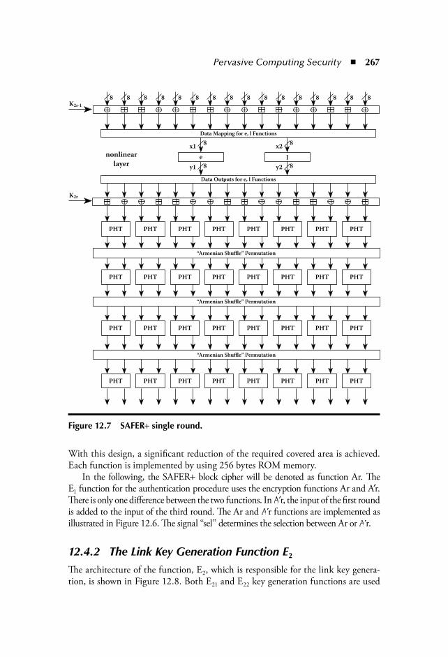
Pervasive Computing Security 267
With this design, a significant reduction of the required covered area is achieved.Each function is implemented by using 256 bytes ROM memory.
In the following, the SAFER block cipher will be denoted as function Ar. TheE1 function for the authentication procedure uses the encryption functions Ar and Ar.There is only one difference between the two functions. In Ar, the input of the first roundis added to the input of the third round. The Ar and Ar functions are implemented asillustrated in Figure 12.6. The signal “sel” determines the selection between Ar or Ar.
12.4.2 The Link Key Generation Function E2
The architecture of the function, E2, which is responsible for the link key genera-tion, is shown in Figure 12.8. Both E21 and E22 key generation functions are used
Figure 12.7 SAFER single round.

268 The Internet of Things
for the creation of the four authentication keys. These functions are implemented byusing mainly the SAFER algorithm. The four keys are grouped in pairs. The unitkey is paired with the combination key, and the initialization key is paired with themaster key. The keys after generation are stored in a 5 128-bit RAM memory.
12.4.3 The E1/E3 Function ArchitectureThe architecture of the E1 and E3 functions are similar, so these architectures wereimplemented in a reconfigurable unit. The only difference is in their expansionsubunit. The expansion subunit expands either the Bluetooth device address or theCOF parameter into a 128-bit vector. The offset module produces the key for theAr function. The Ar function needs 16 cycles in order for a new set of SRES andACO parameters to be produced. If encryption is needed, the Link Manager setsthe encryption mode signal, so the unit operates as E3 function. After 16 cycles, theE3 function creates the encryption key Kc. A detailed diagram of the E1/E3 archi-tecture is illustrated in Figure 12.9.
12.4.4 The E0 Unit ArchitectureTwo components are needed for the implementation of the E0 stream cipher func-tion unit (Figure 12.10). The first is the payload key generator component, which
random number
random number
random number
random number
random number
KCurrent
KMaster
KMaster
KINIT
OVL from
Verifier
OVL
To Claimant
KUnit
KAB
Sel
Sel
L
L
DE–MUX
MUX
Bluetooth deviceaddress A
Bluetooth deviceaddress B
To other
unit
From other
unit
E21
E21
E22
E22
Figure 12.8 E2 function architecture: unit-, combination-, initialization-, and master key production.
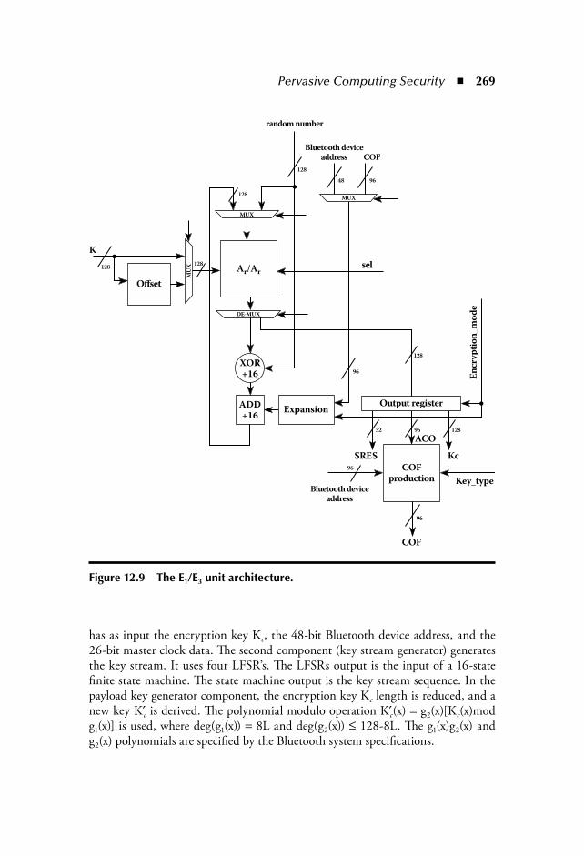
Pervasive Computing Security 269
has as input the encryption key Kc, the 48-bit Bluetooth device address, and the26-bit master clock data. The second component (key stream generator) generatesthe key stream. It uses four LFSR’s. The LFSRs output is the input of a 16-statefinite state machine. The state machine output is the key stream sequence. In thepayload key generator component, the encryption key Kc length is reduced, and anew key K c is derived. The polynomial modulo operation K c(x) g2(x)[Kc(x)modg1(x)] is used, where deg(g1(x)) 8L and deg(g2(x)) 128-8L. The g1(x)g2(x) andg2(x) polynomials are specified by the Bluetooth system specifications.
96
96
96
96
9648
32 128
128
128128
128
128
Figure 12.9 The E1/E3 unit architecture.

270 The Internet of Things
12.5 Bluetooth Enhanced Security Layer (ESL) Hardware Implementation
This section presents a new ESL for improving the security of Bluetooth technol-ogy. The security level is increased by replacing the original Bluetooth encryptionwith a design based on advanced encryption algorithm (AES) [8]. ESL adds MACs(media access controls) to the transmitted data for cryptographic integrity protec-tion. The proposed layer is added on the top of the standard Bluetooth controllerinterface, which allows integrating it as an additional module into any standardBluetooth chip or as a software layer into a host.
This section also presents a prototype implementation of ESL. For high perfor-mance and low energy, the security processing of ESL is implemented in hardware.The design supports the new Counter mode with Cipher block-chaining Messageauthentication code (CCM) encryption mode [9], which is adopted into severalwireless IEEE standards, e.g., 802.11i. Thus, the same hardware design can be uti-lized in other standard implementations. In addition to the enhanced security, the
Payload keygenerator
Key streamgenerator
encryption key Kc
Bluetooth device address
master clock data
Payload key plain text / cipher text
cipher text / plain text
LFSR 1
LFSR 2
LFSR 3XOR
XOR
Init
ial
Val
ue
/2++
LFSR 4
Summation Combiner Logic
Encryption Stream Zt
Blend
z–1
z–1
T2
T1
Figure 12.10 E0 function architecture.
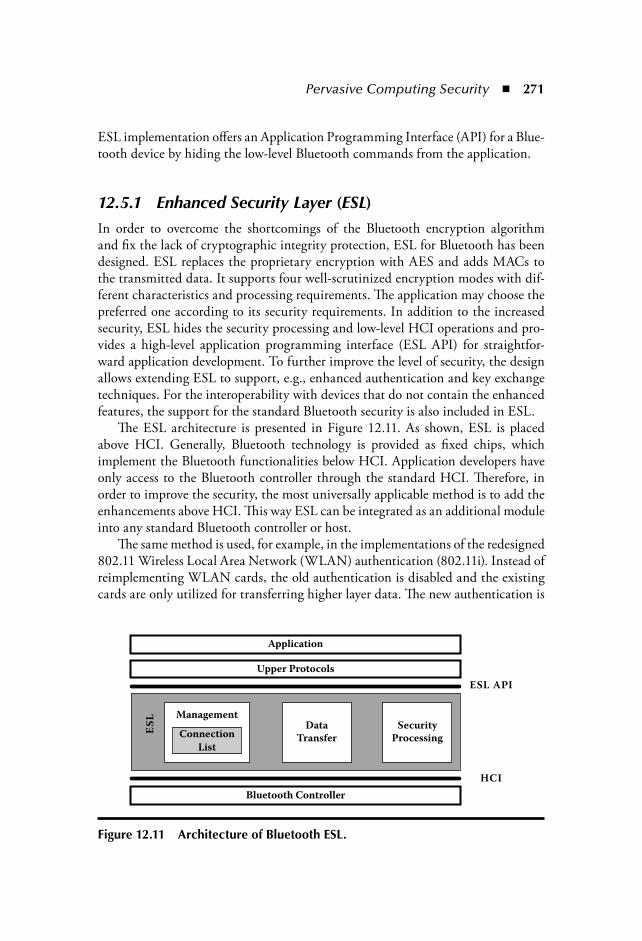
Pervasive Computing Security 271
ESL implementation offers an Application Programming Interface (API) for a Blue-tooth device by hiding the low-level Bluetooth commands from the application.
12.5.1 Enhanced Security Layer (ESL)In order to overcome the shortcomings of the Bluetooth encryption algorithmand fix the lack of cryptographic integrity protection, ESL for Bluetooth has beendesigned. ESL replaces the proprietary encryption with AES and adds MACs tothe transmitted data. It supports four well-scrutinized encryption modes with dif-ferent characteristics and processing requirements. The application may choose thepreferred one according to its security requirements. In addition to the increasedsecurity, ESL hides the security processing and low-level HCI operations and pro-vides a high-level application programming interface (ESL API) for straightfor-ward application development. To further improve the level of security, the designallows extending ESL to support, e.g., enhanced authentication and key exchangetechniques. For the interoperability with devices that do not contain the enhancedfeatures, the support for the standard Bluetooth security is also included in ESL.
The ESL architecture is presented in Figure 12.11. As shown, ESL is placedabove HCI. Generally, Bluetooth technology is provided as fixed chips, whichimplement the Bluetooth functionalities below HCI. Application developers haveonly access to the Bluetooth controller through the standard HCI. Therefore, inorder to improve the security, the most universally applicable method is to add theenhancements above HCI. This way ESL can be integrated as an additional moduleinto any standard Bluetooth controller or host.
The same method is used, for example, in the implementations of the redesigned802.11 Wireless Local Area Network (WLAN) authentication (802.11i). Instead ofreimplementing WLAN cards, the old authentication is disabled and the existingcards are only utilized for transferring higher layer data. The new authentication is
Application
ESL API
HCI
ES
L
Upper Protocols
Bluetooth Controller
Connection
List
ManagementData
TransferSecurity
Processing
Figure 12.11 Architecture of Bluetooth ESL.
272 The Internet of Things
performed above the old WLAN link layer. This requires only reimplementing thesoftware in the host computers.
Another advantage of placing ESL on the top of HCI and not into the basebandis that the method results in lower packet overhead. Added protocol fields are trans-mitted in the HCI data packets instead of every Bluetooth network packet.
12.5.2 Enhanced Security DesignThe AES algorithm [8] utilized in ESL is a symmetric cipher that encrypts datain 128-bit blocks. It supports key sizes of 128, 192, and 256 bits. As several otherblock ciphers, AES consists of successive, similar iteration rounds. Depending on thechosen key size, the number of the rounds is 10, 12, or 14. Each round mixes the datawith a round key, which is generated from the encryption key. Currently, the 128-bitkey version is generally considered to provide adequate security and it is also utilizedin this work. Decryption requires inverting the iterations resulting in at least partlyseparate data paths. However, the encryption modes of ESL only use the forwardcipher.
Applying an encryption algorithm alone without a proper encryption mode isnot secure. The counter mode (CTR) [10] is generally regarded as a good choiceand it is also utilized in ESL. CTR has a proven security bound [14] and it pro-vides most performance trade-offs for implementations. In CTR a block cipherproduces a key stream from a secret key and a counter. The key stream is generateda block at a time by encrypting counter values until the stream length matches thedata length. After each algorithm pass, the counter is incremented. The stream isexclusive-ored (XOR) with the plaintext to get the ciphertext and vice versa. If thedata length is not a multiple of the block length, only the required bits of the lastkey stream block are used. It is important that the same counter value is used onlyonce during the lifetime of a key. Another security requirement is that at maximum264 encryptions are to be performed per key.
The CTR mode requires that the encrypted data is accompanied with MAC.Otherwise, the bit manipulation attacks of section II-A still apply. In this work,MAC is computed using the cipher block chaining MAC (CBC-MAC) method.This allows utilizing the same algorithm for both encryption and data authentica-tion. CBC is a feedback encryption mode in which the previous ciphertext blockis XORed with the plaintext block before encryption. CBC-MAC operates in thesame way, except that only the result of the last encryption is output as MAC.CBC-MAC is security proof [11].
ESL supports plain CBC-MAC (MAC mode) and two combinations of theCTR encryption and CBC-MAC computation. In the combined modes, MACmay be computed over the plaintext (MAC-then-encrypt mode) or over the cipher-text (encrypt-then-MAC mode). The phases utilize separate keys. In the MAC-then-encrypt mode, MAC is encrypted. The MAC mode is suited for applicationsin which privacy is not required. The combined modes provide both privacy and
Pervasive Computing Security 273
authenticity. In [12], it has been shown that the encrypt-then-MAC mode is gen-erally secure. However, for example, in [13], it is suggested that it should be theplaintext that is authenticated. Adding the other mode to a design that implementsone of the modes requires only little additional resources. Thus, both the modes aresupported in ESL.
In addition, ESL supports a special MAC-then-encrypt mode, CCM [9]. Origi-nally CCM was proposed to the IEEE 802.11i working group for improving thesecurity of the IEEE 802.11 WLAN. It was also adopted. Later it had been sentfor evaluation as a standard block encryption mode. The described components ofthe mode, CTR and CBC-MAC, have been well known for decades, but CCM is anew definition for their combined usage. The security of the CCM mode has beenproven in [14].
Whereas the CTR encryption can process arbitrary length data, CBC-MACrequires that the input is padded to match a block boundary. In ESL, the last inputdata block is padded with zeroes if required in all the modes. The padding doesnot affect CTR. Instead, the en/decrypted output is truncated back to the originallength. The MAC size can be chosen to be 64 or 128 bits, which allows trade-offsbetween the protection level and communication overhead. If the 64-bit MACis chosen, the 64 least significant bits of the MAC output are discarded. MAC isappended to the HCI payload data.
In order to prevent repeated counter values, the CTR counter is composed ofconcatenated nonce and block counter values in all the combined modes. The nonceis a constant value for a transmission and the block counter is incremented for eachdata block within the transmission. The nonce is provided by the application. Forexample, [9] presents recommendations for choosing the nonce in CCM. Goodpractice is to include at least the sender’s Bluetooth address and the transmissionssequence number in the nonce. In the presented work, the nonce size was chosento be 96 bits to allow including sufficient amount of information in it. Thus, theblock counter size is 32 bits. In addition to the nonce, in CCM there are fixed flagsin the CTR input. In the presented approach, the flags are regarded as a part of thenonce.
Since ESL is located above the standard HCI, only the data placed in the HCIdata packet payloads can be encrypted. However, the application can protect theknown Bluetooth packet header fields (e.g., Bluetooth addresses) with MAC. Inaddition, the application must ensure that the nonce can be generated at the receiv-ing device. The generation data can be predefined or transmitted in the HCI datapackets. It does not have to be kept secret, as long as it is protected with MAC.
The format of an ESL packet, placed in the HCI data payload, is presented inFigure 12.12. The maximum size of the application data per ESL packet dependson the chosen MAC size. It is assumed that the complete nonce is transmitted in anESL packet. If a combined mode is chosen, the ESL payload field is encrypted. TheHCI payload is transmitted in a Bluetooth ACL network packet. If the HCI pay-load does not fit into a single network packet, the Bluetooth controller automatically
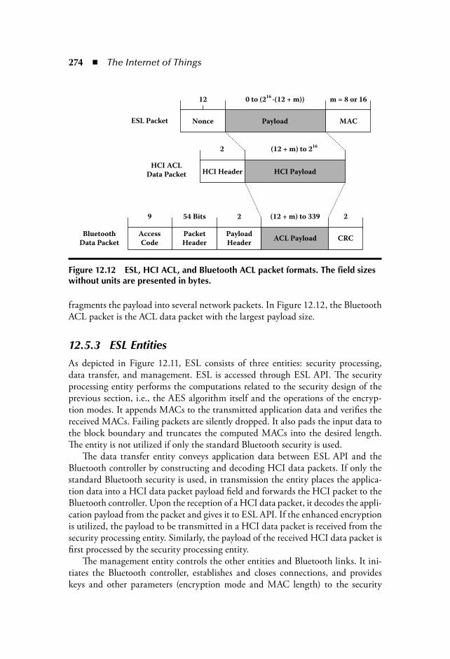
274 The Internet of Things
fragments the payload into several network packets. In Figure 12.12, the BluetoothACL packet is the ACL data packet with the largest payload size.
12.5.3 ESL EntitiesAs depicted in Figure 12.11, ESL consists of three entities: security processing,data transfer, and management. ESL is accessed through ESL API. The securityprocessing entity performs the computations related to the security design of theprevious section, i.e., the AES algorithm itself and the operations of the encryp-tion modes. It appends MACs to the transmitted application data and verifies thereceived MACs. Failing packets are silently dropped. It also pads the input data tothe block boundary and truncates the computed MACs into the desired length.The entity is not utilized if only the standard Bluetooth security is used.
The data transfer entity conveys application data between ESL API and theBluetooth controller by constructing and decoding HCI data packets. If only thestandard Bluetooth security is used, in transmission the entity places the applica-tion data into a HCI data packet payload field and forwards the HCI packet to theBluetooth controller. Upon the reception of a HCI data packet, it decodes the appli-cation payload from the packet and gives it to ESL API. If the enhanced encryptionis utilized, the payload to be transmitted in a HCI data packet is received from thesecurity processing entity. Similarly, the payload of the received HCI data packet isfirst processed by the security processing entity.
The management entity controls the other entities and Bluetooth links. It ini-tiates the Bluetooth controller, establishes and closes connections, and provideskeys and other parameters (encryption mode and MAC length) to the security
ACL Payload
HCI Header HCI Payload
Payload MAC
CRCPayload
Header
Packet
Header
Bluetooth
Data Packet
HCI ACLData Packet
ESL Packet Nonce
9 54 Bits 2 2(12 + m) to 339
2 (12 + m) to 216
12 0 to (216
–(12 + m))
Access
Code
m = 8 or 16
Figure 12.12 ESL, HCI ACL, and Bluetooth ACL packet formats. The field sizes without units are presented in bytes.

Pervasive Computing Security 275
processing entity. The management entity constructs HCI commands and receivesinformation from the Bluetooth controller in HCI events. The controller initiationconsists of preparing the device to function as a slave or a master and, if the stan-dard security is applied, providing the controller with the security parameters.
Another major responsibility of the management entity is to maintain a con-nection list, which contains handles to the established Bluetooth links and theirESL parameters, i.e., the encryption and MAC keys and chosen MAC length. Ifthe enhanced security is not utilized for a link, the management entity sets ESL tobypass the enhanced security processing. Otherwise the entity advises the securityprocessing entity to en/decrypt the HCI data payload and, if valid, give it to thedata transfer entity for further processing.
The ESL processing and HCI are hidden behind the high-level ESL API. Itprovides procedures for device initiation, connection establishment, sending andreceiving application data, and disconnecting. After the initialization, the securityprocessing is transparent to the application. The interface is only requested to trans-mit or receive application data and provide nonces.
12.5.4 Prototype ArchitectureThe architecture of the ESL prototype is presented in Figure 12.13. The compo-nents implemented in the hardware (PLD) were Direct Memory Access (DMA),
Application
ARM9 Processor
ESL API
HAL
AHB Bridge
AHB
Slave
SecurityProcessing
UART UART
BluetoothController
SDRAM
HCI
LowerLayers
Programmable Logic Device
Control DMA
Interrupts AHB Bridge
Figure 12.13 ESL prototype architecture.
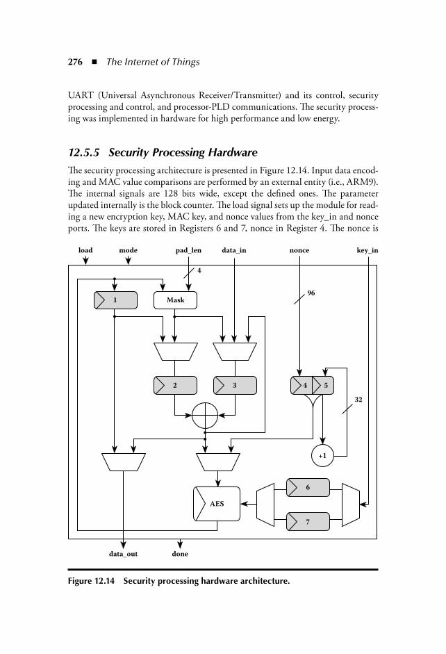
276 The Internet of Things
UART (Universal Asynchronous Receiver/Transmitter) and its control, securityprocessing and control, and processor-PLD communications. The security process-ing was implemented in hardware for high performance and low energy.
12.5.5 Security Processing HardwareThe security processing architecture is presented in Figure 12.14. Input data encod-ing and MAC value comparisons are performed by an external entity (i.e., ARM9).The internal signals are 128 bits wide, except the defined ones. The parameterupdated internally is the block counter. The load signal sets up the module for read-ing a new encryption key, MAC key, and nonce values from the key_in and nonceports. The keys are stored in Registers 6 and 7, nonce in Register 4. The nonce is
load
1
2 3 4 5
32
+1
6
7
AES
96
4
Mask
mode pad_len data_in
data_out done
key_innonce
Figure 12.14 Security processing hardware architecture.

Pervasive Computing Security 277
concatenated with the block counter in Register 5. The load port also allows main-taining the old key values and updating only the nonce. The block counter is resetby updating the encryption key or nonce.
Feeding a new data block is done through the data_in port. The block is storedin Register 3. The signal mode defines whether the module operates in the MAC,MAC-then-encrypt, encrypt-then-MAC, or CCM mode and sets the module toencrypt or decrypt. The pad_len signal is used for informing the number of pad-ding bytes in the last input block. This information is required in the combinedmodes. The data_out port is used for outputting the en/decrypted data blocks aswell as the MAC values.
In the MAC mode, MAC is computed using the MAC key. The chaining valuein Register 1, obtained after processing the previous data block, is transferred toRegister 2. Initially, the value is zero. After XORing the chaining value with the datablock in Register 3, the result is processed by the AES core and the output is writtenback to Register 1. After the last data block, the contents of Register 1 are output andthe register is reset. The MAC verifications are carried out in the same way.
In the MAC-then-encrypt mode, first, the design performs the MAC computationfor a block with the MAC key as described. Then, the operation is switched to the CTRencryption with the encryption key. In CTR, the nonce and the block counter are fedto the AES core. Initially, the block counter is set to zero. The result is written throughthe mask block to Register 2 and XORed with the data block maintained in Register3. Finally, the result is output and the block counter is incremented. After the last datablock, the nonce and the block counter are processed once more and the result is writtento Register 3 (through the mask entity). The contents of Register 1 are transferred toRegister 2 and XORed with Register 3. The result is output as the encrypted MAC.
In the encrypt-then-MAC mode, the processing order of MAC-then-encrypt isinverted. The only difference is that after encrypting a data block, the output is alsowritten back to Register 3 for the MAC computation.
In the MAC-then-encrypt decryption, the processing is mainly the same asin the encrypt-then-MAC encryption. After the last data block, the received,encrypted MAC is input through data_in to Register 3. The nonce and the blockcounter are input to the AES core. XORing the AES output with Register 3 yieldsthe decrypted MAC, which is output for comparison with the earlier output, com-puted MAC. The encrypt-then-MAC decryption processing is the same as theMAC-then-encrypt encryption processing. The received MAC is not input since itis already in the plaintext form.
The CCM mode operation is similar to the MAC-then-encrypt mode. Theencryption and MAC keys are set to the same value. The difference is that inthe CCM mode the block counter starts initially from 1 and the MAC value isencrypted/decrypted with the block counter value zero.
If the data length is not a multiple of 16 bytes, the last output en/decrypted datablock has to be truncated to the original length. This implies the need for the maskentity in the encrypt-then-MAC encryption, MAC-then-encrypt decryption, and
278 The Internet of Things
CCM decryption. Before XORing the last key stream block with the data block,the bytes of the key stream block corresponding to the extra bytes (zeroes) of thedata block have to be masked to zero. This way the XOR result of the input blockand the last key stream block, which is used as the input in the MAC computation,has the correct padding (zeroes). The mask logic is implemented with a ROM, con-taining 16 masking entries of size 16 bytes, and an AND gate.
12.5.6 CommunicationAs shown in Figure 12.13, the external Synchronous Dynamic Random AccessMemory (SDRAM) is used for data transfers between the Advanced RISC Machine(ARM9) and the Programmable Logic Device (PLD) in the implementation. Theexternal memory is larger than the fixed-size Dual Port Random Access Memory(DPRAM) and it can be switched, which makes the ESL implementation scalablefor processing larger amounts of data. By sharing SDRAM, the processor does nothave to transfer the data from the data memory in SDRAM to DPRAM for thePLD usage. Instead, the PLD can access SDRAM directly, which is faster and letsthe ARM9 perform other tasks concurrently. The DMA entity was implementedfor the purpose in the PLD. It accesses the memory via an Advanced High Per-formance Bus (AHB) bridge. An UART entity was implemented in the PLD fortransferring data between the development board and the Bluetooth controller.
The data transferred through SDRAM consists of HCI commands and data to theBluetooth controller, HCI events and data from the controller, and the data to/fromthe security processing entity. The nonce, encryption and MAC keys, and the UARTinitialization data are also conveyed through the memory. The nonce and keys are onlytransmitted to the security processing entity when the values are initialized or changed.
After writing a HCI command or data to SDRAM, the ARM9 utilizes theother AHB bridge for initiating operations in the PLD. The control entity receivesthe processor requests through the AHB slave in Figure 12.13. The slave containslogic for interfacing the AHB bus as well as control and memory address registers towhich the ARM9 requests are written from the bus. Depending on the request, thecontrol entity begins an UART transmission of a HCI command or the en/decryp-tion of data. ARM9 is interrupted after an operation is finished. The processorreads the reason for the interrupt from the AHB slave.
When a HCI data packet is received from the Bluetooth controller, it is writ-ten to SDRAM by DMA and the ARM9 is interrupted. If the packet payload isnot encrypted, the processor decodes the packet and gives the ESL payload to theapplication. Otherwise, it provides the security processing entity with the keys andnonce for decrypting the payload. When the payload is decrypted, the ARM9 isagain interrupted. If a MAC scheme is used, the processor verifies that the receivedand computed MAC values match and conveys the data to the application.
Each HCI command has a corresponding event (acknowledgment) with whichthe Bluetooth controller replies to the command. In addition, the network operations

Pervasive Computing Security 279
trigger events. For simplicity and removing unnecessary memory accesses, the PLDcontrol entity filters out the events uninteresting to the processor.
The communications between Bluetooth devices utilize the access control list(ACL) link. The used ACL packet types can be defined with a HCI command.
12.5.7 Software InterfacesIn Figure 12.13, hardware abstraction layer (HAL) implements the ESL function-alities on the ARM9 side. It constructs HCI commands and data and reads HCIevents from SDRAM as well as decodes payload data from the HCI data packets. Italso handles the interrupts initiated by the PLD. HAL controls the security process-ing entity and UART by modifying the memory mapped control and address reg-isters in the AHB slave. HAL allows utilizing the Bluetooth’s own security featuresas well as choosing among the enhanced security implementations. If an enhancedsecurity mode is utilized, upon the reception of a HCI data packet, HAL comparesthe MAC values. It also pads the input data and truncates MACs.
The ESL API implementation provides procedures for initiation, connectionmanagement, and sending and receiving application data. A pseudo-code exampleof the API usage is presented in Figure 12.15.
In the example, first, the Bluetooth device is initialized. It is defined that thestandard security features are not used. The InitBd procedure returns the uniqueBluetooth address of the controller and the maximum size of the payload for asingle transmission. After the initialization, the device is able to operate in the slave
void main() {. . .//initialize Bluetooth device://authentication disabled, no link key type defined, no PIN inputInitBd(FALSE, NULL, NULL, OwnBdAddress, payloadMaxSize);
//set device into master and scan devices nearbyPrepareMaster (numberOfResponses, deviceArray);
//set values for Bluetooth’s own link key and for the keys of the end enhanced//encryption and data authentication, choose encrypt–then–MACSetEncMode (NULL, encKey, macKey, ENC_THEN_MAC);
//create connection to the first found device with the security parameters aboveConnectToBd (deviceArray[0], connectionHandle);
//send data to the connected deviceTransmitData (connectionHandle, payloadSize, payload, nonce);
//close connectionDisconnect (connectionHandle);}
Figure 12.15 A pseudo-code example of using the ESL API implementation. Values for the parameters in italics are returned by the procedure calls.

280 The Internet of Things
mode. Next, the role of the device is switched to the master mode. The Prepare-Master procedure also scans for devices in the range and returns a list of founddevice addresses. Before connecting to a device, the parameters for the enhancedsecurity features are set. Successful connection creation returns the handle of thecreated link. Application data can be sent over the link with a single procedure call.The data size must respect the maximum payload size defined in the initialization.Finally, the connection is closed.
Even though not utilized in the example, each procedure also returns a Booleanvalue that informs whether the performed operation was successful or not. Forexample, if the transmit buffer of the Bluetooth controller is full, the Transmit-Data procedure fails. Changing the security parameters requires closing the linkand calling the InitBd and/or SetEncMode procedures again. The application mustimplement a separate callback procedure for receiving data. Upon the reception of adata packet, the procedure is automatically called by the ESL API implementation.Similarly to the standard Bluetooth, the implemented software enables up to sevensimultaneously active Bluetooth connections.
12.6 Bluetooth Security Implementation Based on Software-Oriented Hardware–Software Partition
In this section, a hybrid implementation in software and hardware of the Blue-tooth security algorithm is presented. Software-oriented and hardware–softwarepartitioning methods are applied to this design and resource-sharing scheme is alsoadopted. The partitioning and resource sharing reduce hardware resources, thoughthe timing requirement is fulfilled.
12.6.1 Constructing Block Ciphering Functions in SoftwareIn the present approach, the block ciphering functions have been implemented insoftware. E1, E21, E22, and E3 functions are analyzed and broken down to subfunc-tions. Ar and A r functions are computed from the same function with differentmode values 0 and 1, respectively. They are basic functions for constructing thehash function. Figure 12.16 shows the relation of above functions.
Ex functions (x 1, 21, 22, and 3) can be made with these basic subfunctions, Ar,Ar, and hash functions. E1 and E3 functions are hash functions themselves with Lvalues, 6 and 12, respectively. Namely, E1 (RAND, K, address) equals hash (RAND,K, address, 6), and E3 (K, RAND, address, ACO) equals hash (K, RAND, COF,12). E21 and E22 functions use Ar function whose input parameters are modifiedfrom original input parameters. Therefore, E21(PIN, address) equals Ar(X(RAND),Y(address)), and E22(PIN, RAND) equals Ar(X (PIN), Y (RAND)).

Pervasive Computing Security 281
12.6.2 Timing Analysis of Block Ciphering FunctionsRegarding the system level analysis, the subfunctions were simulated on MS-Windows -based Pentium PC and measured each relative running time. The cal-culation time of key_gen function or t_key is 16.13 msec, and the calculation timeof encrypt function or t_enc is 7.31 msec. Ar or Ar function needs t_Ar or 23.72msec in its calculation, and the hash function needs t_hash or 47.44 msec. Because(t_key t_enc) is about 98.82/100 of t_Ar and the double of t_Ar is 99.54/100 oft_hash, t_key and t_enc are critical calculation times in Ar and hash functions.
12.6.3 Timing Constraint of Block Ciphering FunctionsGeneration of each key and authentication are accomplished by link manager pro-tocol (LMP) between Bluetooth devices. For example, if devices have a link keyand want to authenticate each other, the verifier sends a random value with LMP_au_rand command in link manager level, and claimant returns SRES value, whichis calculated with received random value using LMP_sres command. The verifierchecks correspondence of its SRES and received SRES from claimant. LMP_sresis a response command of a LMP_au_rand command. The Bluetooth specifies theallowable response time of link manager command as 30 sec. Because within 1slot time or 0.625 usec, the link manager command can be translated to the linkcontrol command and the link control command can operate the baseband block;the time constraint of each Ex function can be 29 sec to satisfy the Bluetooth speci-fication. Even though the specification allows 30 sec to receive response command
Figure 12.16 Constructing subfunctions. Ar, A’r, and hash functions.

282 The Internet of Things
in link manager level, we set time constraint of each Ex function to 30 msec, 1,000times smaller than what is given in the specification, in our design for fast key gen-eration and authentication.
12.6.4 Timing Measurement of Block Ciphering Functions in Embedded MCU
In this Bluetooth design, it has used a Multipoint Control Unit (MCU) based onthe SE3208 core, which is one of 32-bit extendable instruction set computer (EISC)processors made by Advanced Digital Chips, Inc., Korea [15,16]. EISC possessesadvantages over existing Complex Instruction Set Computer (CISC) and ReducedInstruction Set Computer (RISC) architectures. EISC can represent any length ofan operand without variable length instruction eliminating inefficiencies caused bydifficulties in processing variable instruction decoding. EISC’s fixed length instruc-tion set maximizes cost/performance efficiency and at the same time offers flexibilityand power through the extendable register and extension flag, which increase thecode density while allowing a simple 16-bit-based instruction set. To measure thetiming of the block ciphering functions in a 32-bit EISC processor, it uses Jupiter,which includes the same 32-bit EISC processor that it was intended to use [17]. Theoperating clock of Jupiter is set to 20 MHz, which is the same system clock of ourBluetooth design. The operating times of E1, E21, E22, and E3 functions are 22.462msec, 11.842 msec, 11.516 msec, and 22.584 msec, respectively. Because these valuessatisfy the defined timing constraint of 30 msec, the block ciphering functions can beoperated in EISC MCU without any replacement to hardware block.
12.6.5 Constructing and Analysis of Stream Ciphering Function
Bluetooth uses stream ciphering function, E0 to encrypt or decrypt the payload of thepackets. The E0 function includes the payload key generation function to generate keystream. It means the E0 function consists of the payload key generation function and keystream generation function. At the system level analysis, payload key generation func-tion and the key stream generation function take 17.82 msec and 93.74 msec, respec-tively. In this analysis, because one operation of the key stream generation functionmakes 128 bits, each bit takes about 1/128 of 93.74 msec or 0.732 msec to generate.
Bluetooth specification requires that a payload key should be generated for eachpayload. If Bluetooth operates with DM1 packet type, it can transmit maximally17 bytes or 136 bits in one slot timing, 0.625 msec. It needs one calculation ofpayload key generation and 136 bits generation of key stream. The payload keygeneration function needs 89.10 msec and the 128-bit key generation functiontakes 107.70 msec on an EISC processor with 20 MHz clock. Because neither thepayload key generation nor key stream generation can be run within one slot time,0.625 msec, all of them should be designed as hardware modules.
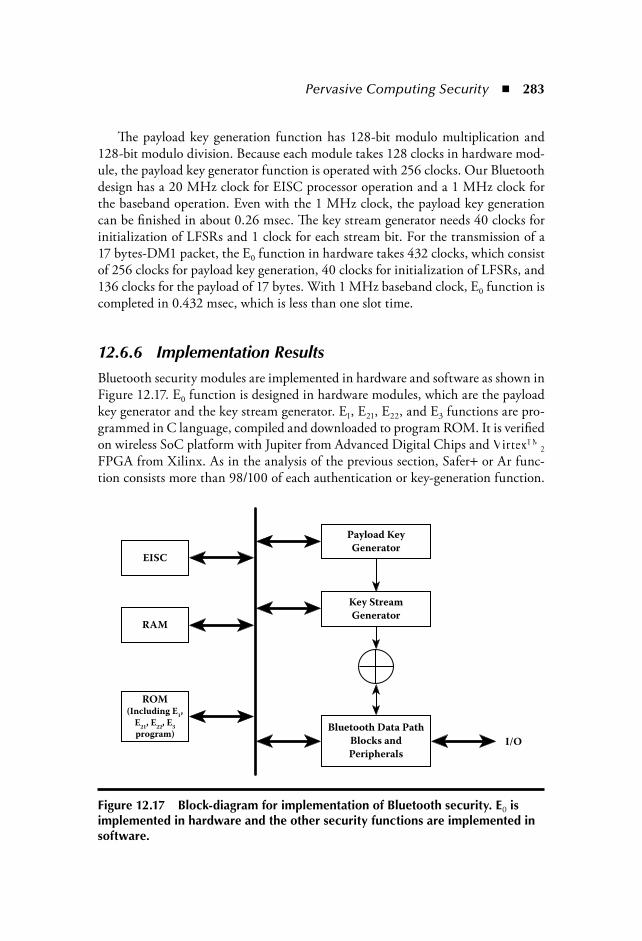
Pervasive Computing Security 283
The payload key generation function has 128-bit modulo multiplication and128-bit modulo division. Because each module takes 128 clocks in hardware mod-ule, the payload key generator function is operated with 256 clocks. Our Bluetoothdesign has a 20 MHz clock for EISC processor operation and a 1 MHz clock forthe baseband operation. Even with the 1 MHz clock, the payload key generationcan be finished in about 0.26 msec. The key stream generator needs 40 clocks forinitialization of LFSRs and 1 clock for each stream bit. For the transmission of a17 bytes-DM1 packet, the E0 function in hardware takes 432 clocks, which consistof 256 clocks for payload key generation, 40 clocks for initialization of LFSRs, and136 clocks for the payload of 17 bytes. With 1 MHz baseband clock, E0 function iscompleted in 0.432 msec, which is less than one slot time.
12.6.6 Implementation ResultsBluetooth security modules are implemented in hardware and software as shown inFigure 12.17. E0 function is designed in hardware modules, which are the payloadkey generator and the key stream generator. E1, E21, E22, and E3 functions are pro-grammed in C language, compiled and downloaded to program ROM. It is verifiedon wireless SoC platform with Jupiter from Advanced Digital Chips and VirtexTM
2
FPGA from Xilinx. As in the analysis of the previous section, Safer or Ar func-tion consists more than 98/100 of each authentication or key-generation function.
Bluetooth Data Path
Blocks and
PeripheralsI/O
Key Stream
Generator
Payload Key
GeneratorEISC
RAM
ROM(Including E
1,
E21
, E22
, E3
program)
Figure 12.17 Block-diagram for implementation of Bluetooth security. E0 is implemented in hardware and the other security functions are implemented in software.
284 The Internet of Things
By replacing only Safer function in hardware, operating time can be reduced con-siderably. With verilog code of Safer provided by Cylink Corporation, as shownin Figure 12.17, it has been constructed in hardware module with 1 MHz clock,which is the same as other Bluetooth baseband modules. C Program for BluetoothSecurity is just changed from calling Safer subroutine or Ar in software to call-ing it in hardware. It executes E1, E21, E22, and E23 functions in 0.887 msec, 0.337msec, 0.287, and 0.851 msec, respectively.
12.7 ConclusionIn this chapter, an analytical description of the hardware architecture and imple-mentation of the Bluetooth security, dictated by the official specifications waspresented. Also, an implementation of a new enhanced security layer (ESL) is pre-sented. The security level is increased by replacing the encryption with AES andadding integrity protection. The security processing is implemented in hardware forhigh performance. Finally, a partitioning hardware and software implementationwas introduced.
ESL significantly improves the Bluetooth security by replacing the proprietaryencryption with an AES-based design and adding cryptographic message integ-rity verification. In addition to the security enhancements, an easy-to-use API wasdesigned. The API implementation offers an application developer-simple accessto the wireless link and transparent security processing. The throughput of theimplemented security processing hardware is 214 Mb/s with the modes offeringthe highest security level. This implies only a negligible processing latency, which isalso lower than that of the standard security design.
Comparing the hardware implementation with the hybrid one (software andhardware), we notice that the proposed hardware modulo multiplier takes 256clocks, whereas that in hybrid design takes 128 clocks. Even though overall hard-ware resources for E0 function are similar, the number of slices and slice flip-flopsin hybrid design are less than in the strict hardware implementation results, but thenumber of function generators in hybrid is larger than in hardware. The hardwareresources of hybrid design are about 1/20 times than that of strict hardware. Thenumber of slices, slice flip-flops, and function generators of hybrid and strict hard-ware are 770, 1,219, and 1,100 and 19,905, 2,600, and 42,764, respectively.
Security in pervasive computing is a complex issue and is getting a lot of nega-tive reactions through poor implementations being brought to market (i.e., IEEE802.11b). Many of the lower-level protocols are not secure and the use of the mostsecure higher-level protocols is limited. Bluetooth has the potential to enhance andextend the pervasive applications because it is well suited to pervasive devices andmobile applications.
Over the past three decades, we have labored under the constraint that securecryptosystems required too much computation to be performed easily. These

Pervasive Computing Security 285
constraints are disappearing. Moore’s Law is producing general-purpose proces-sors that can handle the necessary crypto functions in a negligible fraction of theircapacity. Tiny special-purpose chips can also be produced inexpensively for fulfill-ing the crypto demands of special applications. Thus, we are about to be freed fromthe constraints of the past. This is even true for public key schemes. These algo-rithms, crucial for digital signatures and key management, do not require the com-municating parties to possess a shared key that only they have. The computationalrequirements of these methods are still considerably higher than for symmetricones, but progress in electronics is overcoming even this barrier.
Most of the single chip Bluetooth baseband implementations, which include alow performance general-purpose processor, implement only the data encryption inhardware. But, in time-critical applications where a fast connection solution is nec-essary and in devices with very high processing tasks, the hardware implementationof the key generation mechanism and the authentication is also preferable.
References [1] Bluetooth Special Interest Group, Specification of the Bluetooth System, vol. 1.1,
February 22, 2001. Available: http://grouper.ieee.org/groups/802/15/Bluetooth/ [2] J. Beutel, O. Kasten, A Minimal Bluetooth-Based Computing and Communica-
tion Platform, Technical Note, May 2001. [3] R. Barber, Security in a Mobile World—is Bluetooth the Answer? Computers and
Security, 20, 5, Elsevier Advanced Technology, 2001, pp. 371–379. [4] J.L. Massey and R. Rueppel, Linear ciphers and random sequence generators with
multiple clocks, Advances in Cryptology: Proceedings of EUROCRYPT 84, vol. 209of Lecture Notes in Computer Science, pp. 74–87, Springer-Verlag, Heidelberg,Germany, April 1984.
[5] P. Kitsos, N. Sklavos, K. Papadomanolakis, and O. Koufopavlou, Hardware imple-mentation of the Bluetooth security, IEEE Pervasive Computing, Mobile and Ubiq-uitous Systems, 2, 1, Jan.–Mar. 2003, pp. 21–29.
[6] P. Hamalainen, N. Liu, R. Sterling, M. Hannikainen, T.D. Hamalainen, Designand implementation of an enhanced security layer for Bluetooth, The 8th Inter-national Conference on Telecommunications, ConTEL 2005, Zagreb, Croatia, June15–17, 2005.
[7] G. Lee and S.-Chong Park, Bluetooth security implementation based on softwareoriented hardware–software partition, 2005 IEEE International Conference on Communications, (ICC 2005), Seoul, Korea, May 2005.
[8] Advanced Encryption Standard (AES), Federal Information Processing StandardsStd. FIPS-197, 2001.
[9] D. Whiting, R. Housley, and N. Ferguson (January 2003) Counter with CBC-MAC (CCM)—AES mode of operation. Available: http://csrc.nist.gov/CryptoToolkit/modes/proposedmodes/ccm/ccm.pdf.
[10] H. Lipmaa, P. Rogaway, and D. Wagner (October 2000) CTR-mode encryption.
286 The Internet of Things
[11] M. Bellare, J. Killian, and P. Rogaway, The security of the cipher block chain-ing message authentication code, Journal of Computer and System Sciences, 61, 3:362–399, 2000.
[12] H. Krawczyk, The order of encryption and authentication for protecting communi-cations (or: How secure is SSL?). In Proc. 21st Annu. Int. Cryptology Conf. on Advances in Cryptology (CRYPTO 2001), Santa Barbara, CA, August 2001, pp. 310–331.
[13] N. Ferguson and B. Schneier, Practical Cryptography. John Wiley & Sons, NewYork, 2003.
[14] J. Jonsson, On the security of CTR CBC-MAC. In Proc. 9th Annu. Int. Workshop on Selected Areas in Cryptography (SAC 2002), St. John’s, Newfoundland, Canada,August 2002, pp. 76–93.
[15] Adchips Inc., “EISC Architecture Smaller, Faster, Cheaper, all at Low Power,” athttp://www.adc.co.kr.
[16] H.-G. Kim, D.-Y. Jung, H.-S. Jung, Y.-M. Chio, J.-S. Han, B.-G. Min, andH.-C. Oh, AE32000B: A fully synthesizable 32-bit embedded microprocessor core,ETRI Journal, 25, 5, 337–344, October 2003.
[17] Adchips Inc., Jupiter Data Book, v 1.1, September 2002, at http://www.adc.co.kr.

287
Chapter 13
Internet of Things: A Context-Awareness Perspective
Davy Preuveneers and Yolande Berbers
Contents13.1 Introduction ......................................................................................288
13.1.1 Software Architecture and the Internet of Things .....................28813.1.2 Context Awareness and the Internet of Things ...........................28913.1.3 Convergence as a Key Enabler for the Internet of Things ...........290
13.2 State-of-the-Art on Context-Aware Computingfor Nonintrusive Behavior.......................................................................29013.2.1 A Definition of Context .............................................................29113.2.2 Using RFID to Sense Context....................................................29113.2.3 Requirements for Representing and Exchanging Context ..........292
13.3 Trends in Context-Aware Computing within Service Orientation ..........29613.3.1 Context-Enabled Service Oriented Architecture
and the Semantic Web................................................................29613.3.2 Context-Enabled Service Delivery Platforms..............................297
13.4 Service Provision in a Context-Aware, Converged ServiceArchitecture............................................................................................29913.4.1 Context Management as an Enabling Service ...........................30013.4.2 Conveying Context and Distributed Storage..............................301

288 The Internet of Things
13.1 IntroductionThe next wave in the era of computing will be outside the realm of the traditionaldesktop. In the Internet of Things* paradigm (IoT) [22], everything of value willbe on the network in one form or another. Radio frequency IDentification (RFID)and sensor network technologies will give rise to this new standard, in which infor-mation and communication are invisibly embedded in the environment aroundus. Everyday objects, such as cars, coffee cups, refrigerators, bathtubs, and moreadvanced, loosely coupled, computational and information services will be in eachothers interaction range and will communicate with one another. Large amounts ofdata will circulate in order to create smart and proactive environments that will sig-nificantly enhance both the work and leisure experiences of people. Smart interact-ing objects that adapt to the current situation without any human involvement willbecome the next logical step to people already connected anytime and anywhere.With the growing presence of WiFi and 3G wireless Internet access, the evolutiontoward ubiquitous information and communication networks is already evidentnowadays. However, for the Internet of Things vision to successfully emerge, thecomputing criterion will need to go beyond traditional mobile computing scenariosthat use smartphones and portables, and evolve into connecting everyday existingobjects and embedding intelligence into our environment. For technology to dis-appear from the consciousness of the user, the Internet of Things demands: (1) ashared understanding of the situation of its users and their appliances, (2) softwarearchitectures and pervasive communication networks to process and convey thecontextual information to where it is relevant, and (3) the computational artifactsin the Internet of Things that aim for autonomous and smart behavior. With thesethree fundamental grounds in place, smart connectivity and context-aware compu-tation via anything, anywhere, and anytime can be accomplished.
13.1.1 Software Architecture and the Internet of ThingsAny software architecture, designed to be deployed within the setting of the Inter-net of Things, will need to foresee the increasing heterogeneity of devices andnetworks, and will have to provide for varying user and application requirementswithin diverse contexts of service provision. It will be essential for new architectures
* Internet of Things refers to a ubiquitous network society in which a lot of objects are“connected.”
13.5 Context Awareness from RFID to the End-Userin the Internet of Things.........................................................................303
13.6 Conclusions.......................................................................................30413.7 Open Issues ............................................................................................305References .........................................................................................................305

Internet of Things: A Context-Awareness Perspective 289
to integrate the latest technologies in the areas of software and hardware in order toassimilate as much as possible data and services available in the environment of theuser. As service integration-related tasks will remain inevitable, it is no surprise thatthe industry is aiming for software solutions that make this integration a more trac-table activity. The evolution toward integrated service orientation is already emerg-ing in the ongoing convergence of Web services and telecommunication services [21].Service-Oriented Architecture (SOA) [27] is an architectural style that enables thecomposition of applications by using loosely coupled and interoperable services.These often transaction-based services are described and exposed using open stan-dards—in the case of Web services using WSDL, SOAP, and BPEL [40]—that areindependent of the underlying programming language and platform. The telecom-munications world has embraced the Service Delivery Platform (SDP) architecturalapproach to enable more flexible communication and collaboration services by evolv-ing to all-IP (Internet Protocol) networks for the delivery of multimedia-enabled andlocation- or presence-aware services. Due to its event-driven communication para-digm, an SDP differs from the previous architectural style in that a SOA typicallydoes not need to meet any real-time demands for its data-driven communication.Both SOA and SDP software architectures commonly provision service orchestra-tion capabilities by exposing their services using open standards, and often sharebuilding blocks to handle noncore functionalities, such as authentication, identitymanagement, and billing. As a result, converged services bring us the flexible interac-tions from the Web service paradigm, nicely integrated with the communication andcollaboration services from the telecommunications world. Key to the success of theInternet of Things will be the ability to connect everyday objects, including RFIDtags and other existing resources, to such service-oriented architectures so that it willlead to an overall flexible architecture that aims to create a pleasant user experienceat the workplace, in public areas as well as in the home environment.
13.1.2 Context Awareness and the Internet of ThingsContext awareness plays an important role in the aforementioned software archi-tectures to enable services customization according to the current situation withminimal human intervention. Acquiring, analyzing, and interpreting relevant con-text information [11] regarding the user will be a key ingredient to create a wholenew range of smart entertainment and business applications that are more support-ive to the user. Although context-aware systems have been in the research epicenterfor more than a decade [32,33], the ability to convey and select the most appropri-ate information to achieve nonintrusive behavior on multiuser-converged serviceplatforms in mobile and heterogeneous environments remains a significant man-agement challenge. Interoperability at the scale of the Internet of Things should gobeyond syntactical interfaces and requires the sharing of common semantics acrossall software architectures. It also demands a seamless integration of existing com-putational artifacts (hardware and software) and communication infrastructures.

290 The Internet of Things
Only then can context information be successfully shared between highly adaptiveservices across heterogeneous devices on large-scale networks that consider thisinformation relevant for their purposes.
13.1.3 Convergence as a Key Enabler for the Internet of Things
In summary, the Internet of Things is all about convergence, from connected com-puting using RFID and sensor technology to digital content and context-awareservices, an observation that was also made in the digital lifestyle chapter of thedigital.life ITU Internet Report 2006 [23]. The success of the Internet of Things willnot so much depend on the development of new technologies, but more so on con-necting and integrating existing resources, ranging from small-scale objects, suchas RFID tags, up to large-scale software systems that serve thousands of clients at atime. The goal is to create a software architecture that enables objects to exchangeinformation through the Internet to achieve nonintrusive behavior and custom-ized services. Part of the architecture’s responsibility is to make sure that relevantinformation arrives at the right place in a way that the recipient understands whatit receives. Here, we investigate how such an architecture can be designed by inte-grating innovative scientific results from related research domains with industrialtechnologies and practices with a proven track record.
In section 13.2, we describe the current state-of-the-art in context-awarecomputing and discuss the goals, motivation, and requirements that define theactual need for context awareness in order to achieve a better understanding ofthe concepts involved. We review the trends for its use in converging service-oriented architectures in section 13.3. To illustrate the benefits of introducingcontext awareness as one of the underpinning fundamentals of the Internet ofThings, we also elaborate on our recent research activities at the architectural levelin section 13.4. It illustrates how to integrate existing technologies and computa-tional artifacts supporting context awareness as an enabling service amongst otherbuilding blocks in an overall service-oriented architecture for use in home appli-ances and online consumer services. By not reinventing the wheel, but insteadleveraging on solid foundations from the software and knowledge engineeringdomains, nothing stands in the way for applications targeting the Internet ofThings model to become a success.
13.2 State-of-the-Art on Context-Aware Computing for Nonintrusive Behavior
The notion of context is widely understood in the pervasive and ubiquitous com-puting domain as relevant information referring to the situation and circumstancesin which a computational artifact is embedded. As such, context awareness is the

Internet of Things: A Context-Awareness Perspective 291
ability to detect and respond to contextual changes. The goal of context-aware com-puting is to gather and utilize information to positively affect the provisioning ofservices that are considered appropriate for a particular person or device. There-fore, context information can only be considered useful if it can be interpreted. Ascontext is a rather vague concept, we first mention how context has been definedby leading experts in the field before continuing to describe how context can bemodeled, acquired, and used to achieve autonomous and nonintrusive behavior ina service-oriented architecture.
13.2.1 A Definition of ContextMany authors initially defined context information by enumerating types of infor-mation related to the user or application environment that seemed relevant. Theterm context was first used by Schilit and Theimer [32] to refer to “location, identi-ties of nearby people and objects, and changes to these objects.” Brown, Bovey, andChen [6] have defined context as “location, identities of the people around the user,the time of day, season, temperature, etc.” Ryan, Pascoe, and Morse [31] referredto context as “the user’s location, environment, identity, and time.” Dey [10] listed“the user’s emotional state, focus of attention, location and orientation, date andtime, objects and people in the user’s environment” as elements being part of thedefinition of context. As the use of enumerations to describe context was too lim-ited to analyze whether certain information could be classified as context, Deyet al. [1] provided the following more general and widely accepted definition thatencompasses the previous ones:
Context is any information that can be used to characterize the situ-ation of entities (i.e., whether a person, place or object) that are con-sidered relevant to the interaction between a user and an application,including the user and the application themselves. Context is typicallythe location, identity and state of people, groups and computationaland physical objects.
Therefore, context involves relevant information on real world entities. Thisinformation needs to be described in a structured and easily extensible model tofacilitate the sharing of collected information. Therefore, it is impossible to limitcontext information to a fixed set of attributes or properties.
13.2.2 Using RFID to Sense ContextRFID is an emerging technology for embedding sensing capabilities in every-day objects [39] and is gaining momentum as a popular means for automatic
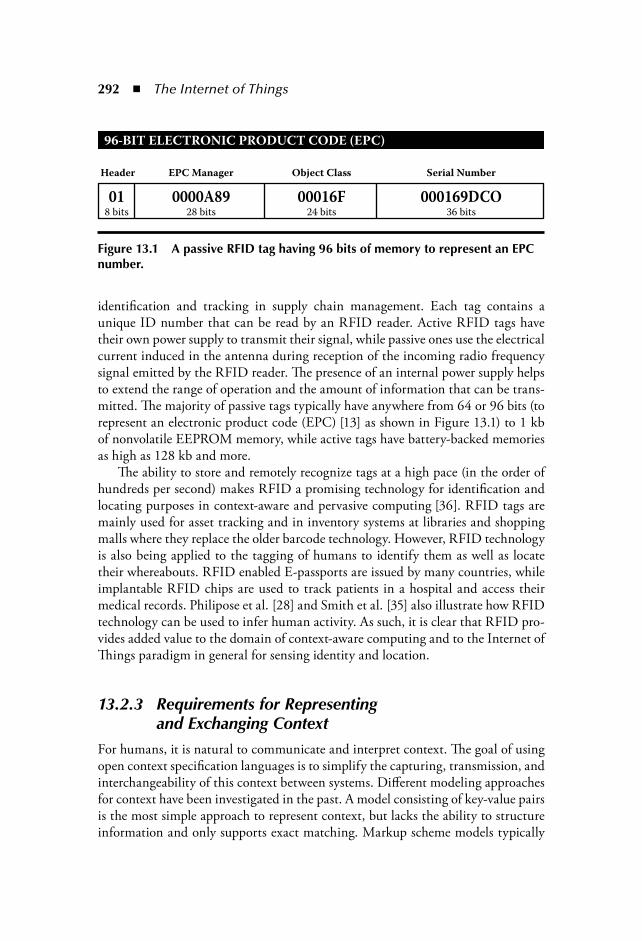
292 The Internet of Things
identification and tracking in supply chain management. Each tag contains aunique ID number that can be read by an RFID reader. Active RFID tags havetheir own power supply to transmit their signal, while passive ones use the electricalcurrent induced in the antenna during reception of the incoming radio frequencysignal emitted by the RFID reader. The presence of an internal power supply helpsto extend the range of operation and the amount of information that can be trans-mitted. The majority of passive tags typically have anywhere from 64 or 96 bits (torepresent an electronic product code (EPC) [13] as shown in Figure 13.1) to 1 kbof nonvolatile EEPROM memory, while active tags have battery-backed memoriesas high as 128 kb and more.
The ability to store and remotely recognize tags at a high pace (in the order ofhundreds per second) makes RFID a promising technology for identification andlocating purposes in context-aware and pervasive computing [36]. RFID tags aremainly used for asset tracking and in inventory systems at libraries and shoppingmalls where they replace the older barcode technology. However, RFID technologyis also being applied to the tagging of humans to identify them as well as locatetheir whereabouts. RFID enabled E-passports are issued by many countries, whileimplantable RFID chips are used to track patients in a hospital and access theirmedical records. Philipose et al. [28] and Smith et al. [35] also illustrate how RFIDtechnology can be used to infer human activity. As such, it is clear that RFID pro-vides added value to the domain of context-aware computing and to the Internet ofThings paradigm in general for sensing identity and location.
13.2.3 Requirements for Representing and Exchanging Context
For humans, it is natural to communicate and interpret context. The goal of usingopen context specification languages is to simplify the capturing, transmission, andinterchangeability of this context between systems. Different modeling approachesfor context have been investigated in the past. A model consisting of key-value pairsis the most simple approach to represent context, but lacks the ability to structureinformation and only supports exact matching. Markup scheme models typically
96–BIT ELECTRONIC PRODUCT CODE (EPC)
Header
8 bits
0128 bits
0000A8924 bits
00016F36 bits
000169DCO
EPC Manager Object Class Serial Number
Figure 13.1 A passive RFID tag having 96 bits of memory to represent an EPC number.

Internet of Things: A Context-Awareness Perspective 293
introduce a fixed structure and allow to express more complex relations, such asassociations. These types of models are frequently used to capture user profiles(e.g., Friend of a Friend (FOAF) [5]) and device profiles (e.g., Composite Capabli-ties/Preferences Profile (CC/PP) [24] and User Agent Profile (UAProf) [16]). Sofar, ontologies, providing a specification of a conceptualization [17], seem to bethe most promising way to go when modeling context [37,7,18,38]. Ontologiesare well known in the knowledge representation community to model conceptsand the relationships that hold among them and their semantic interpretationis universally accepted. Figure 13.2 illustrates a graphical representation of the
Activity Role
Profile
Mood
User
HardwareSoftware
Platform
Environment
Resource
I/O
Environmental ConditionTimeLocation
has Time
has Location
has Environment
requires Platform
provides Software
provides Service
uses Service
provides Hardware
is a
uses IO Devicehas Task
has Activity has Role has Mood
has Profile
has Profile has Profile
association
has Environmental Condition
Class
Service
Task
ONTOLOGY–BASED MODELING OF CONTEXT–AWARENESS
Figure 13.2 The CoDAMoS context ontology that models the user, platform, service, and environment concepts and interrelationships with other relevant classes.
294 The Internet of Things
Context-Driven Adaptation of Mobile Services (CoDAMoS) context ontology [30].Many dedicated and XML-based languages exist to model ontologies, but the bestknown language is the Web Ontology Language (OWL) [20], a markup language forpublishing and sharing data using ontologies on the World Wide Web. Following is areview of some of the main requirements for an open context specification to be usedfor exchange between computational artifacts in the Internet of Things:
Comprehensive domain coverage and terminology: An open context spec-ification language should make available a terminology that provides appro-priate coverage and a comprehensive representation of a domain in order tomodel most of the concepts and terms needed for describing entities in aparticular domain. Concepts may be modeled with multiple synonymousrepresentations and may have hierarchical relationships to other concepts. Semantic nonambiguity and expressiveness: Information semanticsinvolve the uniform interpretation of a concept. This requires a strict sup-port for nonambiguity in the specification language to ensure that eachconcept in the terminology has only one meaning. Semantic expressivenessis the ability to easily enhance the knowledge domain using the semanticprimitives of the specification language. More advanced semantic specifi-cation languages for context provide support to model specialization andinheritance relationships, aggregation, dependencies and constraints, etc. Processing complexity: Some languages require quite complex processingsteps for both the data acquisition and processing (e.g., reasoning and infer-ence) parts. For example, context models using Resource Description Frame-work (RDF) [4] or OWL [20] may refer to other remotely available contextmodels to detail the semantics and relationships of concepts being reused.This, of course, is a good thing as it improves knowledge sharing, interoper-ability, and universal interpretation. However, it also increases the complexityto process context models. As the Internet of Things targets computationalartifacts of different shapes and sizes, an appropriate balance should be foundbetween processing complexity and language expressiveness. Specification language interoperability: There is no one single specifi-cation that will solve all issues with respect to context provisioning in anopen fashion. For some purposes, the use of a particular domain-specificlanguage may already be so pervasive that this in itself would be one ofthe reasons not to reimplement the same concepts in another more genericspecification language. Therefore, the ease of reusing and integrating differ-ent dedicated specification languages is also an important concern.
For information to be processed automatically, it goes without saying that themarkup needs to conform to a standard format that is accepted by as many partiesas possible. Open standards are a hot topic at present for exchanging documentsin a format that can be read and modified by different parties. A lot of attention ispaid to XML formats as the Holy Grail for interchangeability. However, for context
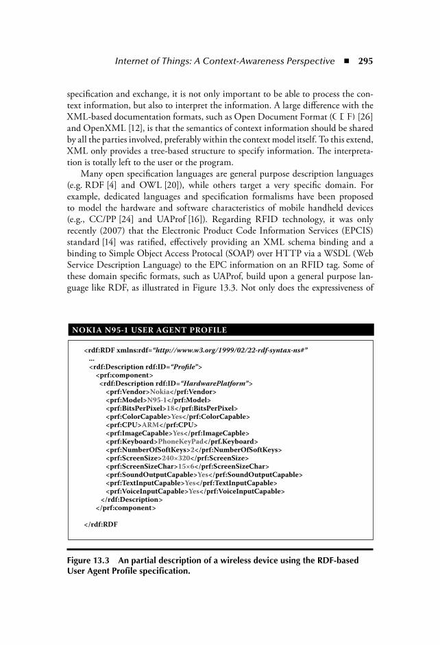
Internet of Things: A Context-Awareness Perspective 295
specification and exchange, it is not only important to be able to process the con-text information, but also to interpret the information. A large difference with theXML-based documentation formats, such as Open Document Format (ODF) [26]and OpenXML [12], is that the semantics of context information should be sharedby all the parties involved, preferably within the context model itself. To this extend,XML only provides a tree-based structure to specify information. The interpreta-tion is totally left to the user or the program.
Many open specification languages are general purpose description languages(e.g. RDF [4] and OWL [20]), while others target a very specific domain. Forexample, dedicated languages and specification formalisms have been proposedto model the hardware and software characteristics of mobile handheld devices(e.g., CC/PP [24] and UAProf [16]). Regarding RFID technology, it was onlyrecently (2007) that the Electronic Product Code Information Services (EPCIS)standard [14] was ratified, effectively providing an XML schema binding and abinding to Simple Object Access Protocal (SOAP) over HTTP via a WSDL (WebService Description Language) to the EPC information on an RFID tag. Some ofthese domain specific formats, such as UAProf, build upon a general purpose lan-guage like RDF, as illustrated in Figure 13.3. Not only does the expressiveness of
NOKIA N95–1 USER AGENT PROFILE
<rdf:RDF xmlns:rdf=“http://www.w3.org/1999/02/22–rdf–syntax–ns#” ... <rdf:Description rdf:ID=“Profile”> <prf:component> <rdf:Description rdf:ID=“HardwarePlatform”> <prf:Vendor>Nokia</prf:Vendor> <prf:Model>N95–1</prf:Model> <prf:BitsPerPixel>18</prf:BitsPerPixel> <prf:ColorCapable>Yes</prf:ColorCapable> <prf:CPU>ARM</prf:CPU> <prf:ImageCapable>Yes</prf:ImageCapble> <prf:Keyboard>PhoneKeyPad</prf.Keyboard> <prf:NumberOfSoftKeys>2</prf:NumberOfSoftKeys> <prf:ScreenSize>240×320</prf:ScreenSize> <prf:ScreenSizeChar>15×6</prf:ScreenSizeChar> <prf:SoundOutputCapable>Yes</prf:SoundOutputCapable> <prf:TextInputCapable>Yes</prf:TextInputCapable> <prf:VoiceInputCapable>Yes</prf:VoiceInputCapable> </rdf:Description> </prf:component>
</rdf:RDF
Figure 13.3 An partial description of a wireless device using the RDF-based User Agent Profile specification.
296 The Internet of Things
these languages differ, they also distinguish themselves in managing or processingcomplexity. As such, there is no single one-fits-all context specification language.
13.3 Trends in Context-Aware Computing within Service Orientation
Though efforts in context awareness research only seem to reach the public at a slowpace, we notice that the need for knowledge engineering methodologies becomes agrowing concern in the design of software architectures when building user-awareservices. These evolutions become apparent in both the SOA world of IT services, aswell as for the SDPs of the telecommunications domain. Any software architecturefor the Internet of Things will face the same concerns, but at a much larger scaleas the number of information-sharing entities will, in the end, outnumber humancommunication.
13.3.1 Context-Enabled Service Oriented Architecture and the Semantic Web
Service Oriented Architecture (SOA) represents the current state-of-the-art in soft-ware architecture for the rapid deployment of new services. It enables the creationof new services or applications by connecting together existing services and pro-poses functions to manage the service life cycle. The main motivation behind SOAfor a company is to create a business-aligned architecture to better react to chang-ing customers’ needs. If the market changes, new services can be created by reusingexisting services and by developing new services where needed. A SOA also enablesa company to leverage previous infrastructure investments, by exposing legacy ser-vices as traditional services in the architecture: A SOA increases code reuse andmodularity.
A service-oriented architecture targeting the growing proliferation of RFID-equipped devices within the Internet of Things, where each computational artifactmay access multiple services within diverse contexts, will become a daunting taskwithout proper identity management. The use of context awareness helps to pro-vide more fine-grained access control to information and services. One illustrationof this trend is presented in the work of Ardagna et al. [3] where position, move-ment, and interaction predicates are introduced in authorization policies relying onGroupe Spécial Mobile (GSM)/third-generation (3G) technologies to achieve loca-tion-constrained access. With the introduction of the E-passport, fitting in RFIDinformation into policy enforcement rules is just a small step. For managing theinformation flow in the Internet of Things, context awareness is becoming a muchlarger concern in SOA than it is at the moment.

Internet of Things: A Context-Awareness Perspective 297
Another emerging trend is coming from the Semantic Web community.Although the WSDL [8] has been very successful as a syntactic specification lan-guage to interact with Web services using different backend environments, it doesnot provide any support for a consistent interpretation of the Web service content.The use of ontologies has already gained much attention for the semantic modelingof context, as illustrated in Figure 13.4. The application of ontologies is also find-ing its way in new Web service specifications, including OWL-S [25], METEOR-S [34], WSDL-S [2], WSMO [9,15], and others, to augment service descriptions inorder to automate their discovery, composition, and invocation in pervasive com-puting environments. The services, that were previously only described by theirpublic invocation interfaces, are now enriched with machine-interpretable seman-tics by referring to and reasoning on established ontologies that encapsulate themeaning of the service. Also, for the Internet of Things, the use of ontologies withinthe architecture may help to make sense of it all, for both the context informationas well as the services being offered.
13.3.2 Context-Enabled Service Delivery PlatformsDuring the last decade, the telecommunications world has transformed radicallydue to the shift toward Internet-style infrastructures for the delivery of multimedia-enabled communication services. Today’s very popular, IP-based VoIP (Voice overInternet Protocol) systems are the result of the evolution from monolithic and iso-lated infrastructures to service delivery platforms that adopt the IP network as their
Reasoning
Interference
Equivalence
Location Time
SUMO WSMO
CC/PPFOAF
PIDF RPID
EPC
Figure 13.4 Aligning context awareness and standardized specifications for the Internet of Things along the Semantic Web “layer cake” (Courtesy of T. Berners-Lee).

298 The Internet of Things
communication network and base their operations on open standards and proto-cols. These service delivery platforms enable a richer communication experience byproviding services that go beyond leaving a voice message when your friend doesnot answer his cell phone. With conventional communication, you have no ideawhen your friend will get your message, perhaps leaving you no choice but to callback several times. If you only knew where your friend was at that moment .
Presence and availability are just two of the main features that these SDPs offer,together with the adoption of another popular Internet application: Instant Messaging.A presence service enables a selective group of users, the “buddy list,” to be notified ofyour availability and your preferred way of communication (mail, telephone, instantmessaging, etc.). This information is passed on using the Session Initiation Protocol(SIP). Similar to HTTP and SOAP for Web services, the SIP [19] is the most impor-tant protocol for Internet telephony, supporting user, session, and service mobility, anda major building block for multimedia and voice services on IP Multimedia Systems(IMS). SIP is under continuous expansion to support new types of communication andinformation that were beyond its scope when it was initially defined. Many of theseadd-on SIP standards are used to sketch the context of the users and their appliances, orto notify remote subscribers of a change in this context:
SIP Specific Event Notification: This is an extension that allows SIPnodes to request information from remote nodes. Being a generic package,it can be used to notify and convey any contextual change to whom it mayconcern when such an event has occurred. Presence Information Data Format (PIDF): This is an XML documentthat provides presence information about a presentity, including statusinformation and optionally contact addresses, timestamps, and textualnotes. An example is given in Figure 13.5.
PRESENCE INFORMATION DATA FORMAT
<?xml version=“1.0” encoding=“UTF–8”?><presence xmlns=“urn:ietf:params:xml:nspidf”
entity=“pres:[email protected]”> <tuple id=“123456”> <status> <basic>open</basic> </status> <contact priority=“0.75”>tel:+32987654321</contact> <timestamp>2007–03–15T17:26:21Z</timestamp> <note>I am busy right now ...</note> </tuple></presence>
Figure 13.5 Specifying presence within SIP using the basic PIDF format.
Internet of Things: A Context-Awareness Perspective 299
Rich Presence Information Data Format (RPID): This format buildsupon PIDF and adds elements that provide additional information aboutthe presentity* (location, mood, activity, etc.) and its contacts.Other related SIP standards: Common Profile for Preference, CommonProfile for Instant Messaging, Contact Information in Presence Informa-tion Data Format, Timed Presence Extensions to the PIDF, etc.
We can observe that, given the list of SIP specifications and draft recommenda-tions, presence is an important concern in telecommunications. In supply chainmanagement, where RFID technology typically has a strong foothold, presenceand availability play an important role as well. Although products will not directlycommunicate their presence to all interested parties by themselves, it is clear thatthe flexibility of the SIP signaling protocol makes it an excellent candidate to deliverreal-time and up-to-date context information to all subscribers.
13.4 Service Provision in a Context-Aware, Converged Service Architecture
Interoperability between Web service-and telecommunication-oriented architec-tures is a complex issue. A service in SOA is essentially transaction-based and relieson an architecture that often builds upon the functionality of an enterprise servicebus (ESB) to provide message brokering, routing, data translation, and transforma-tion. A service within a SDP needs to deal with a multitude of point-to-point con-nections and short-lived events that must be generated, propagated, and processedwith a low latency to guarantee a minimal quality of service level. The proposedarchitecture for the Internet of Things, therefore, integrates both kinds of servicesat the session level because that is where the interaction between two services startsand where it can benefit the most from context information. As Web services andtelecommunication services use similar though competing standards for informa-tion exchange; an enterprise service bus is used inside the architecture to managethe message conversion and routing during a session. A high-level conceptual over-view of the architecture is given in Figure 13.6.
The goal of introducing context awareness in a converged service-orientedarchitecture is to simplify the discovery of information about an entity when thisinformation cannot be easily searched, is not made explicit in the required format,or needs aggregation with other information sources before it can be used. Ourcontext management system [29] represents itself as an enabling service in the con-verged service-oriented architecture, in a similar way as billing and policy enforce-ment do. Neither of these services provide any functionality directly to the client,but do so to other enabling and end-user services. Similar to billing and policy
* Presentity presentity (presence entity) provides presence information to a presence service(RFC2778).
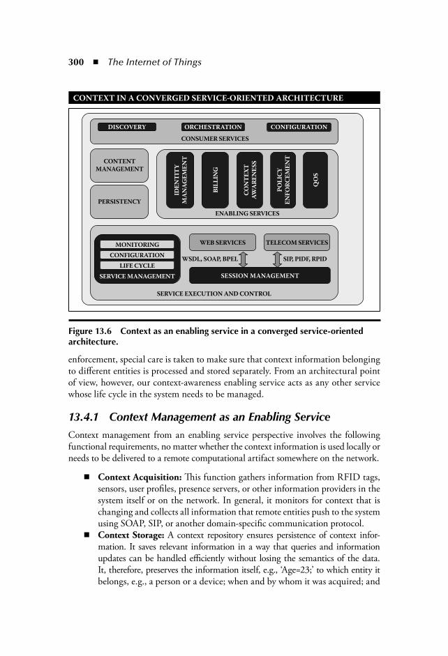
300 The Internet of Things
enforcement, special care is taken to make sure that context information belongingto different entities is processed and stored separately. From an architectural pointof view, however, our context-awareness enabling service acts as any other servicewhose life cycle in the system needs to be managed.
13.4.1 Context Management as an Enabling ServiceContext management from an enabling service perspective involves the followingfunctional requirements, no matter whether the context information is used locally orneeds to be delivered to a remote computational artifact somewhere on the network.
Context Acquisition: This function gathers information from RFID tags,sensors, user profiles, presence servers, or other information providers in thesystem itself or on the network. In general, it monitors for context that ischanging and collects all information that remote entities push to the systemusing SOAP, SIP, or another domain-specific communication protocol. Context Storage: A context repository ensures persistence of context infor-mation. It saves relevant information in a way that queries and informationupdates can be handled efficiently without losing the semantics of the data.It, therefore, preserves the information itself, e.g., ‘Age=23;’ to which entity itbelongs, e.g., a person or a device; when and by whom it was acquired; and
CONTEXT IN A CONVERGED SERVICE–ORIENTED ARCHITECTURE
CONTENT
MANAGEMENT
CONSUMER SERVICES
ENABLING SERVICES
SERVICE EXECUTION AND CONTROL
WEB SERVICES TELECOM SERVICES
WSDL, SOAP, BPEL SIP, PIDF, RPID
ORCHESTRATIONDISCOVERY
IDE
NT
ITY
MA
NA
GE
ME
NT
CO
NT
EX
TA
WA
RE
NE
SS
PO
LIC
YE
NF
OR
CE
ME
NT
QO
S
BIL
LIN
G
CONFIGURATION
PERSISTENCY
MONITORING
CONFIGURATION
LIFE CYCLE
SERVICE MANAGEMENT SESSION MANAGEMENT
Figure 13.6 Context as an enabling service in a converged service-oriented architecture.

Internet of Things: A Context-Awareness Perspective 301
how the information relates to other instantiated context concepts by referringto the right ontology in the semantic knowledge base, also stored in the contextrepository. Context Manipulation: This part aggregates and reasons on context infor-mation to provide information in a suitable format when needed. Besides areasoning engine that exploits semantic relationships within ontologies, theenabling service also provides adapters that transform context informationto change the way information is represented. For example, a temperatureexpressed in C can be translated into F using straightforward conversionrules. Classification sacrifices accuracy of low-level information for the sakeof obtaining more meaningful information. For example, a geographicallocation of longitude and latitude coordinates can be converted into a cityrepresentation. As many application domains propose similar though com-peting standards, part of the manipulation is also to bridge the standardsinteroperability gap where possible.
A high-level overview of the building blocks of the context-awareness enablingservice is given Figure 13.7.
13.4.2 Conveying Context and Distributed StorageAfter having consolidated context information from various acquisition systems(sensors, people, devices, etc.) and remote input channels (services, databases, etc.),the collected information may be selected for distribution to remote subscribers(people, services, devices). When information is gathered from or needs to be
CONTEXT AWARENESS ENABLING SERVICE
USER PROFILE
CONTEXTACQUISTION
CONTEXTSTORAGE
BILLINGPOLICY
ENFORCEMENTPRESENCE
SERVERDATABASE
SENSORSRFID
CONTEXTMANIPULATION
SERVICE CUSTOMIZATION
CONTEXT AWARENESS ENABLING SERVICE
ONLINE MUSICSTORE
INSTANTMESSAGING
Figure 13.7 Building blocks of the context awareness-enabling service.

302 The Internet of Things
delivered to a remote entity, choices need to be made on where context will bestored. The obvious choice would be close to the area where it is considered relevant,and perhaps be duplicated if necessary. If context is stored locally on the devicethat sensed the information, it is readily available and round trips on the networkto retrieve the information are avoided. However, if the information is also usefulfor other parties, then it makes sense to store the information remotely on a reposi-tory that is more easily accessible. The following concerns are taken into accountwhether information should be stored locally or remotely:
Scope of relevance: Certain information can be relevant only for compu-tational artifacts that interact in particular with local services. An obviousexample is the intelligent home environment where the information thatphotovoltaic light sensors in the house provide, is not of interest outside thehome environment. Information sensitivity: Tracking information retrieved from RFID tagscould be of interest to multiple parties on the network and be made avail-able on a remote server for further analysis. Personal information, on theother hand, is kept private on purpose and only shared with authorizedentities. Although privacy issues are an important concern in context-awarecomputing, we will not go into detail here as privacy is already covered to alarge extent in other chapters and in the specialized literature. Information currentness and period of relevance: Static and profiledinformation is likely to remain valid for longer periods. For example, theposition of fixed beacons is information that is highly suited for distribu-tion, as synchronization does not need to occur often. Volatile informationon the other hand, such as the current system load, may no longer be accu-rate or relevant when it is finally remotely stored in a repository.Caching for information reachability: If some sensor information can beobtained quite easily, then storing the information may not be worthwhile.However, as some appliances might have no direct connection to contextsensors that provide useful information, a repository with standard SOAPor SIP interfaces can collect and make the information accessible to allinterested parties. Exploiting information history: In some cases, an appliance might wantto exploit the historic values of a certain context attribute in order to derivenew information. For example, by tracking the current position, the traveleddistance can be derived and used to reimburse traveling expenses. Althoughthe information is no longer accurate, it is still considered useful.
It is clear that the software architecture itself cannot always decide if context infor-mation should be distributed or not. The reason for this is that context is all aboutrelevant and useful information and the software architecture must be informed byits clients about what information they consider relevant for their purposes.
Internet of Things: A Context-Awareness Perspective 303
13.5 Context Awareness from RFID to the End-User in the Internet of Things
The digital lifestyle chapter of the digital.life ITU Internet Report 2006 [23]describes several futuristic scenarios toward context-aware services. We will brieflysummarize them and then discuss how our converged service-oriented architecturewould accomplish the tasks in these scenarios if the architecture would be fullyimplemented and deployed on a large scale.
1. You are walking around in the city and your favorite shop calls you on yourmobile phone. It has detected that you are in the neighborhood and wantsto promote some goods you might be interested in.
2. You find the shirt of your dreams, but it is not available anymore in yoursize. You scan the RFID tag to look for branches that have the shirt in stockand request driving directions to the nearest branch.
3. After your shopping expedition, you head back to your car and while goinghome you run low on fuel. The GPS navigation system in your car informsyou about nearby gas stations.
4. The next morning, your umbrella notifies you as you leave for work, thatthe weather forecast appears to predict rain for this evening. So, you betterbe prepared and take along that umbrella.
5. At work, your telephone handset detects a high body temperature. It seemsyou are a bit feverish. The display shows a warning, along with healthcareinformation and contact information of a nearby doctor.
Most of the above scenarios rely on location awareness of the user. This locationcould be obtained using RFID or Bluetooth technology installed in the cell phoneof the client, or from a GPS navigation system in the car. The types of locationinformation is different (identifier, MAC address, latitude, and longitude) and willlikely need to be converted first by the context-awareness-enabling service beforeit can be used by one of the end-user services. Presence awareness comes into playin scenario 1 and 5. The context-awareness-enabling service verifies first using theSIP protocol if the person in question is available and what kind of communicationhe currently prefers, and then sends a message to the corresponding address. Userprofiles are used by the shop owner to link an identity with previously purchasedgoods, and at client side to store the home and work address, the size of your shirt,SIP contact information, etc. Some context information conversion is needed toconvert the current location to a four-letter METAR weather station identifier to getthe local weather report at home and at work. Sensor technology is used to checkthe amount of fuel, to check the body temperature, to detect movements at thefront door of the house, etc. The second scenario could be an orchestration of Webservices that are semantically described using OWL-S. After using SOAP to send

304 The Internet of Things
the EPC of the shirt and the size you need to the Web service, you obtain a list ofaddresses. For each of these addresses, another online route planning service is usedto compute the distance to the nearest branch.
The above scenarios provide a mixture of Web service and telecommunicationservice orchestrations, context awareness, RFID and sensor technology, local andremote services, SIP and SOAP communication, and so on. Although a real-lifedeployment of the architecture has not been done to test the feasibility, we areconfident that our current architecture can accomplish each of these tasks. All therequirements have been covered in the previous sections and interoperability sup-port is built into the architecture to make these scenarios work.
13.6 ConclusionsThe Internet of Things is all about convergence and integration of the latest advance-ments in the research areas of software and hardware with industrial technologiesinvented many decades ago. Indeed, although RFID is one of the cornerstones ofthis new computer paradigm and becoming more widespread nowadays due to itslow production costs, its invention stems from the World War II period when it wasdeveloped for military purposes. In this chapter, we have highlighted two concernsof great importance for the Internet of Things. One comes from the software engi-neering domain, namely the use of a good software architecture style for the designof any software system, and another one is related to the knowledge engineeringdomain and deals with context awareness, also one of the goals of the Internetof Things. Research carried out in the context-aware computing domain aims tocreate a pleasant user experience at the workplace, in public areas as well as in thehome environment by simplifying human interactions with everyday services andmaking them less intrusive. We have discussed how RFID technology can contrib-ute to context awareness as a way to identify and locate everyday objects as well ashumans, for that matter.
We have argued why service orientation is a good architectural style for theInternet of Things because it leverages existing applications by exposing them astraditional services in the architecture. It increases reuse and modularity, speed-ing up the integration effort. We have proposed a service architecture that aimsto bridge context awareness with the worlds of Web services and telecommunica-tion services. Both application domains have contributed in their own way to thedevelopment of context-aware services by standardizing description formats andprotocols to convey relevant information to whom it may concern. Standardizationis good, only if not for the fact that many of them are similar and competing withone another. For this reason, we have introduced context awareness as an enablingservice in the architecture, leveraging information from both areas at a centralplace. The context-awareness-enabling services is responsible for the acquisition,
Internet of Things: A Context-Awareness Perspective 305
persistency, and manipulation of information to make sure that the right informa-tion can be delivered at the right place at the right time.
13.7 Open IssuesDespite the great potential of context awareness for the Internet of Things, thereare still some hurdles to cross that may slow down the adoption of RFID and otheremerging technologies. One of the repercussions of context-aware computing is theinvasion of one’s privacy. While the aim is to increase convenience by reducing theamount of interactions between users and devices, it is of utmost importance to notlose sight of providing a level of user control in order to set the minds at ease. Onlywhen people are part of the Internet of Things and feel in control will this new wayof computing have a chance of being widely adopted.
References [1] G.D. Abowd, A.K. Dey, P.J. Brown, N. Davies, M. Smith, and P. Steggles. Towards
a better understanding of context and context-awareness. In HUC ’99: Proceed-ings of the 1st International Symposium on Handheld and Ubiquitous Computing,304–307, London, 1999. Springer-Verlag, Heidelberg, Germany.
[2] R. Akkiraju, J. Farrell, J. Miller, M. Nagarajan, M.T. Schmidt, A. Sheth, andK. Verma. Web Service Semantics—WSDL-S, v. 1.0, November 2005.
[3] C.A. Ardagna, M. Cremonini, E. Damiani, S. De Capitani di Vimercati, andP. Samarati. Supporting location-based conditions in access control policies. InASIACCS ’06: Proceedings of the 2006 ACM Symposium on Information, Computer and Communications Security, pp. 212–222, New York, 2006. ACM Press.
[4] D. Beckett. RDF/XML Syntax Specification (Revised), February 2004.[5] D. Brickley and L. Miller. FOAF Vocabulary Specification, 2005.[6] P.J. Brown, J.D. Bovey, and Xian Chen. Context-aware applications: From the
laboratory to the marketplace. Pers. Comm., IEEE (see also IEEE Wireless Comm.),4(5): 58–64, 1997.
[7] H. Chen, T. Finin, and A. Joshi. An ontology for context-aware pervasive computingenvironments. Knowl. Eng. Rev., 18(3): 197–207, September 2003.
[8] E. Christensen, F. Curbera, G. Meredith, and S. Weerawarana. Web ServicesDescription Language (WSDL) v. 1.1, March 2001.
[9] J. de Bruijn, C. Bussler, J. Domingue, D. Fensel, M. Hepp, U. Keller, M. Kifer,B. König-Ries, J. Kopecky, R. Lara, H. Lausen, E. Oren, A. Polleres, D. Roman,J. Scicluna, and M. Stollberg. Web Service Modeling Ontology (WSMO), June 2005.
[10] A.K. Dey. Context-aware computing: The CyberDesk project. In Proceedings of AAAI ’98 Spring Symposium, Technical Report SS-98-02, pp. 51–54, Menlo Park,CA, March 1998.
[11] A.K. Dey. Understanding and Using Context. Personal Ubiquitous Comput., 5(1):4–7, February 2001.
[12] Ecma. Standard ECMA-376, Office Open XML File Formats, December 2006.

306 The Internet of Things
[13] EPCglobal. EPCTM Tag Data Standards v. 1.1, Rev.1.24 Standard Specification01, April 2004.
[14] EPCglobal. EPC Information Services (EPCIS) v. 1.0 Specification, April 2007.[15] D. Fensel, H. Lausen, J. de Bruijn, M. Stollberg, D. Roman, and A. Polleres.
Enabling Semantic Web Services: The Web Service Modeling Ontology. Springer-Verlag, Heidelberg, Germany, 2006.
[16] WAP FORUM. UAProf User Agent Profiling Specification, 1999, amended 2001.[17] T.R. Gruber. A translation approach to portable ontology specifications. Knowl.
Acquis., 5(2): 199–220, 1993. [18] T. Gu, X. Wang, H. Pung, and D. Zhang. An ontology-based context model in
intelligent environments. In Proceedings of Communication Networks and Distributed Systems Modeling and Simulation Conference, San Diego, CA, January 2004.
[19] M. Handley, H. Schulzrinne, E. Schooler, and J. Rosenberg. SIP: Session Initia-tion Protocol, March 1999.
[20] I. Horrocks, P.P. Schneider, and F. van Harmelen. From SHIQ and RDF to OWL:The making of a web ontology language. J. Web Semantics, 1(1): 7–26, 2003.
[21] R. Hull. Converged Services: A Hidden Challenge for the Web Services Paradigm.In E. Bertino et al., eds. EDBT, vol. 2992 of Lecture Notes in Computer Science, pp.1–2. Springer-Verlag, Heidelberg, Germany, 2004.
[22] International Telecommunication Union. ITU Internet Reports 2005: The Internet of Things 2005, 7th ed., Geneva, Switzerland, November 2005.
[23] International Telecommunication Union. ITU Internet Reports 2006: digital.life,Geneva, Switzerland, December 2006.
[24] G. Klyne, F. Reynolds, C. Woodrow, H. Ohto, J. Hjelm, M.H. Butler, and L.Tran. Composite Capability/Preference Profiles (CC/PP): Structure and Vocabu-laries 1.0, 2003.
[25] D. Martin, M. Burstein, J. Hobbs, O. Lassila, D. McDermott, S. McIlraith, S.Narayanan, M. Paolucci, B. Parsia, T. Payne, E. Sirin, N. Srinivasan, and K. Sycara.OWL-S: Semantic Markup for Web Services, Release 1.1, November 2004.
[26] OASIS. Open Document Format For Office Applications (OpenDocument) v. 1.0,May 2005.
[27] OASIS. Reference Model for Service-Oriented Architecture, August 2006.[28] M. Philipose, K.P. Fishkin, M. Perkowitz, D.J. Patterson, D. Fox, H. Kautz, and D.
Hahnel. Inferring activities from interactions with objects. IEEE Perv. Comp. 3(4):50–57, 2004.
[29] D. Preuveneers and Y. Berbers. Adaptive context management using a component-based approach. In Nancy Alonistioti and Lea Kutvonen, eds., Proceedings of 5th IFIP International Conference on Distributed Applications and Interoperable Sys-tems (DAIS2005), Lecture Notes in Computer Science (LNCS). Springer-Verlag,Heidelberg, Germany, June 2005.
[30] D. Preuveneers, J. Van den Bergh, D. Wagelaar, A. Georges, P. Rigole, T. Clerckx,Y. Berbers, K. Coninx, V. Jonckers, and K. De Bosschere. Towards an extensiblecontext ontology for Ambient Intelligence. In P. Markopoulos, et al. eds., Second European Symposium on Ambient Intelligence, vol. 3295 of LNCS, pp. 148–159,Eindhoven, The Netherlands, November 2004. Springer-Verlag, Heidelberg,Germany.

Internet of Things: A Context-Awareness Perspective 307
[31] N.S. Ryan, J. Pascoe, and D.R. Morse. Enhanced reality fieldwork: The context-aware archaeological assistant. In V. Gaffney, M. van Leusen, and S. Exxon, eds.,Computer Applications in Archaeology 1997, British Archaeological Reports, TempusReparatum, Oxford, October 1998.
[32] B.N. Schilit and M.M. Theimer. Disseminating active map information to mobilehosts. Network, IEEE, 8(5): 22–32, 1994.
[33] B.N. Schilit, N.I. Adams, and R. Want. Context-aware computing applications.In Proceedings of the Workshop on Mobile Computing Systems and Applications, pp.85–90, Santa Cruz, CA, December 1994. IEEE Computer Society, Washington,D.C.
[34] K. Sivashanmugam, K. Verma, A. Sheth, and J. Miller. Adding semantics to Webservices standards. In Proceedings of the 1st International Conference on Web Services (ICWS’03), pp. 395–401, Erfurt, Germany, June 2003.
[35] J.R. Smith, K.P. Fishkin, B. Jiang, A. Mamishev, M. Philipose, A.D. Rea, S. Roy,and K. Sundara-Rajan. RFID-based techniques for human-activity detection.Commun. ACM, 48(9): 39–44, 2005.
[36] V. Stanford. Pervasive computing goes the last 100 feet with RFID systems. IEEE Perv. Comp., 2(2): 9–14, 2003.
[37] T. Strang, Claudia L. Popien, and Korbinian Frank. CoOL: A context ontologylanguage to enable contextual interoperability. In J.B. Stefani, I. Dameure, and D.Hagimont, eds., LNCS 2893: Proceedings of 4th IFIP WG 6.1 International Confer-ence on Distributed Applications and Interoperable Systems (DAIS2003), vol. 2893 ofLecture Notes in Computer Science (LNCS), pp. 236–247, Paris, November 2003.Springer-Verlag, Heidelberg, Germany.
[38] X.H. Wang, D.Q. Zhang, T. Gu, and H.K. Pung. Ontology-based context model-ing and reasoning using OWL PERCOMW, p. 18, Second IEEE Annual Confer-ence on Pervasive Computing and Communications Workshops, 2004.
[39] R. Want. Enabling ubiquitous sensing with RFID. Computer, 37(4): 84–86,2004.
[40] S. Weerawarana, F. Curbera, F. Leymann, T. Storey, and D.F. Ferguson. Web Ser-vices Platform Architecture: SOAP, WSDL, WS-Policy, WS-Addressing, WS-BPEL, WS-Reliable Messaging, and More. Prentice Hall, New York, March 2005.


309
A
Access password, 133–134, 142ACK, 17–18, 135Acknowledge state, 135Active RFID tags, 6, 7, 21–28, 38, 39–40,
110, 292class, 129geometric context sensitive system, 157–164power conservation and battery life, 22, 24,
26–27range, 21, 28security issues, 25–26, 28, See also Security
protection; Security risks and threatssemiactive tags, 6, 8, See also Semipassive RFID
tagssensors, 24–25standards, 21–24, 39–40
Advanced encryption standard, See AESAdvanced high performance bus (AHB) bridge,
278Advanced RISC machine (ARM9), 278AES, 25, 139, 217, 264, 270, 271Aircraft transponders, 3All-IP networks, 289Amplitude shift keying (ASK) modulation,
18, 21, 133Animal identification and monitoring
applications, 9, 112, 165–183captive animal recorded parameters, 181–182companion animal recorded parameters, 181comparison of methods, 173–174databases, 177–179domestic animal recorded parameters, 180–181ear tags, 168, 172, 174–175, 176electronic ID and data transfer devices,
176–178health parameters, 179
historical and current methods, 168, 170holding identification parameters, 178identification and traceability requirements,
167injectable transponders, 172–173, 183movement parameters, 178–179productive and reproductive data, 179regulations, 174–176ruminal bolus transponder, 171–172, 174security issues, 182–183standards, 168–170, 182tag attachment, 173wild animal recorded parameters, 181
Anonymous ID scheme, 116–117, 141Antenna, 8–9, 14, 16, 19, 38, 110Arbitrate state, 135, 140Asset and vehicle tracking, 186–204
achieving mobility and portability requirements, 189
application cases, 197–204automatic vehicle identification, 202model, 187–189seamless integration, 190security issues, 204Smart RFID Middleware systems, 187, 190,
193–197SOA-Trust, 216technical challenges, 189–190warehouse management, 198–202Wireless Intelligent Terminal, 187, 189,
190–193Asset management system (AMS), 47Authenticated ciphering offset (ASO), 262Authentication, 100
Bluetooth security layer description, 262cipher block-chaining message authentication
code, 270distributed mechanisms, 212
Index

310 The Internet of Things
encryption algorithm, 43–44HB and HB-enhanced protocols, 221lightweight MAP, 219–220MAP, 148, 151–152, 217–222PIN- and PIN list-based, 220–221
Automatic identification data capture (AIDC), 33–35
data capture and processing performance, 47infrastructure, 45–48managing heterogeneous devices, 48SAP Auto-ID infrastructure, 94–95scalability and performance, 48
Automatic vehicle identification, 202
B
Backend system, 6, 111, 186EPC Gen-2 tag security improvement,
149–150Backscatter communication, 8–9, 21, 39, 133Barcode systems, 5, 34, 109
basic technology, 35–36coding scheme, 36–37cost issues, 19limitations of, 34, 35, 36, 38RFID advantages vs., 111, 186, 188UPC, 6–7, 35, 109
Battery life, 22, 24, 26–27, 30, 31BEA WebLogic RFID, 96Birthday attacks, 152Birthday paradox, 138Block ciphering, Bluetooth security specifications,
264–267, 280–282Blocker tags, 116BlockWrite and BlockErase commands, 146–147Bluetooth security, 260–285
architectures and implementations, 264block ciphering specifications, 264–267,
280–282communication, 278–279Enhanced Security Layer (ESL) hardware
implementation, 270–280, 284ESL entities, 274–275ESL prototype architecture, 275–276hardware implementation, 264–267implementation results, 283–284link level functions, 260software interfaces, 279software-oriented hardware-software partition,
280–284specification description, 260–264
Bluetooth technology, 257–260context-aware services and, 303
Bovine spongiform encephalopathy (BSE), 166, 167
BTnodes, 259Bulky movement data compression, 55–56, 60, 79Burst switch, 8, 27
C
Capacitor, 9Captive animals, 181–182Carrier sense multiple access-based (CSMA) anti-
collision protocol, 224CDMA, 192Chaff commands, 121Chained hash scheme, 119Cipher block-chaining MAC (CBC-MAC), 270,
272–273Ciphers, 139CISC architecture, 282Class-1 RFID tags, 128, 129, See also EPC Class-1
Generation-2 standard; Passive RFID tagsClass-2 RFID tags, 129Class-3 RFID tags, 129, See also Semipassive
RFID tagsClass-4 RFID tags, 129, See also Active RFID tagsCold chain, 28Collective imaginaries, 249Colorwave, 224Complex instruction set computer (CISC), 282Composite capabilities/preferences profile
(CC/PP), 293Computer vision, 158Context acquisition function, 300Context-aware computing and services, 287,
289–305converged service architecture, 299–300conveying context and distributed storage,
301–302definition, 291enabling service, 300–301Internet of things and, 290ontologies, 293–294, 297potential future applications, 303–304privacy issues, 305representing and exchanging context, 292–296RFID applications, 291–292service-telecommunications interoperability,
299SOA and the semantic Web, 296–297
Context-enabled service delivery platforms, 297–299
Context storage, 300–302Cooltown, 159

Index 311
Counter mode (CTR), 272–273Cricket project, 159Customer relationship management (CRM),
34Cyclic redundancy check (CRC), 18, 133, 152
D
Data cleaning, 57, 77extensible sensor stream processing,
89–90Data collision, See RFID data collisionData compression, See RFID data warehousing;
RFID-CuboidsData cube model, 58, 77, See also RFID-CuboidsData Encryption Standard (DES), 217Data management, See RFID data managementData management module, 194Data mining, 77, 78, 91Data-on-network system, 96Data tempering, 114Data transfer entity, 274Data warehousing and analysis, See RFID data
warehousingDeactivation attacks, 114Deactivation using induced fields, 121Denial of service (DoS) attacks, 114, 138, 146,
152, 221–222DES, 217Detection units, 121Device controllers, 46Digital.life ITU Internet Report, 290, 303Digital signature-based scheme, 120Directional antenna, 8Direction-sensitive tag entry, 121Distributed greedy algorithm, 223Distributed trust models, 212Double-sideband amplitude shift keying
(DSB-ASK), 133DRER, 88Drill down, 69Dual port RAM (DPRAM), 278Dynamic Relationship ER Model (DRER),
88
E
Ear tags, 168, 172, 174–175, 176Eavesdropping, 26, 114, 138
tag reader protection, 121, 219Edge servers, 46Electrochemical sensors, 29Electromagnetic coupling, 12–15
Electronic Product Code (EPC), 42–43, 55, 109–110, 210, 292
EPCglobal Network, 96Generation-2 standard, See EPC Class-1
Generation-2 standardElliptic Curve Cryptography (ECC) key, 120E-logistics, 208Employee tracking system, See Location tracking,
office environment pilot studyEncryption, 25, 100, 116, 143, See also Hash
functionsactive RFID tags and, 25Bluetooth enhanced security design, 272–273Bluetooth security layer description, 263–264re-encryption, 117RFID-enabled logistics services and, 217
Encryption key generation, 262–263Enhanced EPC tags, 147–149Enhanced Security Layer (ESL), 270–280, See also
Bluetooth securityentities, 274–275hardware implementation, 270–280, 284
Enterprise asset management (EAM), 34Enterprise information servers, 46–47Enterprise information systems (EIS), 34
integrating with identification resources, 48Enterprise resource planning (ERP), 34, 187Enterprise service bus (ESB), 299E-passports, 292, 296EPC bitmap datatype, 90EPC Class-1 Generation-2 standard, 10, 17–18,
43, 128, 132–137data collision solution, 224dense reader operation, 132Gen-1 vs. Gen-2, 131–132parallel tag counting, 132physical layer, 133random or pseudorandom number generation,
139–140read/write speed, 131security analysis, 128, 140–147security improvement, 147–152, See also
Security protectionslot counter, 135, 137tag counting, 131–132tag identification layer, 133tag memory, 133–134tag states, 135–136
EPC coding scheme, 42–43, 109EPC Gen-1 specification, 131–132EPCglobal, 17, 26, 42, 109EPCglobal Network, 95–96, 129EPC Information Service (EPCIS), 26, 96, 194
312 The Internet of Things
EPC list compression, 56, 63EPC tags, See RFID tagsESP, 89–90eSTREAM Project, 139Ethernet, 259Ethnographic approach, 234, 243–245, 253European Article Number (EAN), 109Event filtering, 190, 194–197Event management module, 194Extendable instruction set computer (EISC), 282Extensible sensor stream processing (ESP), 89–90
F
Fading RFID warehouse model, 78Faraday cage, 116Far-field electromagnetic coupling, 12–15FindIT Flashlight, 159FlowCube, 77FlowGraph, 77FM0 encoding, 18, 132, 133Frequency division multiple access (FDMA) anti-
collision protocol, 224Frequency hopping, 132Frequency ranges, 9–11, 31, 38, 223Frequency shift keying (FSK) modulation, 21–22Friend of a friend (FOAF), 293
G
Gen-2 standard, See EPC Class-1 Generation-2 standard
General Identifier (GID), 43Generalized identifiers (gids), 56, 60, 62Geometric context sensitive RFID, 157–164,
See also Radio frequency identification and geometry (RFIG) tag
Global Individual Asset Identifier (GIAI), 43Global positioning system (GPS), 45, 202,
216, 303Global Returnable Asset Identifier (GRAI), 43GPRS, 192Graph coloring problem, 223Graphical user interface (GUI), 189Gray code, 159GSM, 296
H
Handles, 135, 142, 275Hardware Action Group (HAG), 129Hash functions, 117, 138, 141, 217
Bluetooth block ciphering specifications, 280hash chain scheme, 119, 221hash lock, 117–118, 221lightweight MAP, 220randomized hash lock, 118, 139, 221tree-based algorithm, 119universal hash function, 138
HB and HB-enhanced authentication protocol, 221
Health monitoring, 179High frequency (HF) RFID, 10Hoof-and-mouth disease, 166Human location tracking, See Location tracking,
office environment pilot study
I
IBM open network framework, 210–211IBM WebSphere RFID, 96IDEA program, 170, 175Identification automation technologies, 35,
See also specific technologiesIdentify Friend of Foe (IFF) systems, 3, 128IEEE 1451, 24–25IEEE 802.11b, 284Impedance, 9Implantable chips, 112Incremental updating methods, 77–78Industrial, scientific, and medical (ISM) use
frequencies, 10, 190, 223Information table, 61–62Infrared interface, 192Initialization key, 262Injectable transponders, 172–173, 183Instant Messaging, 298Interconnected RFID reader collision model
(IRCM), 225, 227International Committee for Animal Recording
(ICAR) standards, 169–170, 182Internet of things, 210, 288
context awareness and, 287, 289, 303–304, See also Context-aware computing and services
convergence as key enabler, 290EPCglobal Network, 95–96ontologies, 297service-telecommunications interoperability, 299software architecture and, 288–289
Internet telephony, 298Interrogator, See RFID readersInterrogator Talk First (ITF) specification, 133Intrusion detection system (IDS), 212IP Multimedia Systems (IMS), 298

Index 313
ISO 11784, 42, 168–169ISO 11785, 42, 168–169ISO 14223, 42ISO 14443, 42ISO 15693, 42ISO 15961-15963, 42ISO 17363-17368, 42ISO 18000, 42ISO 18000-6C, 17, 43, 131, See also EPC CLass-1
Generation-2 standardISO 18000-7, 21–24, 25ISO standards, 10
J
Jamming, 116, 138, 222Java System RFID software, 95
K
Key management, 261–262Key stream generation function, 282–283Kill command, 20, 26, 31, 116, 142Killed state, 136Kill password, 133–134, 142, 148
L
Layered RFID security solution, 120Library applications, 10, 161–162Lightweight mutual authentication protocol,
219–220Link key generation function, 261–262, 264,
267–268Link level functions, 260Link manager protocol, 281Listen before talk, 11, 132, 224Livestock tracking applications, See Animal
identification and monitoring applicationsLocation tracking, office environment pilot study,
233–254, See also Animal identification and monitoring applications
attitudes and organizational culture, 249–250metallic environment and, 239, 245, 250–251Nationwide office case study, 234–238pilot objectives and methods, 243–245pilot operational phases, 236real-time display, 242, 248sensors, 240space utilization approaches, 235, 239staff communication, 241–242, 247–248, 252staff response, 245–250
study methodology, 243–245, 253study results, 251–252technology, 238–241technology performance, 245–247, 250–251
Location tracking applications, 112, 292Lock command, 144–146Low frequency (LF) RFID, 9–10, 38Low power communication hardware, 27
M
Mad cow disease, 166, 167Magnetic coupling, 11–15Management entity, 274–275Management execution system (MES), 34Manchester encoding, 22, 196Man-in-the-middle attack, 113, 138Map table, 63Master key, 262, 264Master-slave architecture, 17, 22, 262MD5, 138Media access controls (MACs), 270, 277Memory storage, 43
EPC Class-1 Generation-2 standard, 133–134security enhancement, 149
Meta ID, 118, 119Metallic environments, location tracking system
performance and, 239, 245, 250–251METEOR-S, 297Middleware, 88–89, 91, 93–96, 100, 190,
193–197Milk production, 179Miller encoding, 18, 132, 133Minimalist cryptography, 117, 141Moore’s Law, 285Multipoint control unit (MCU), 282Mutual authentication protocol (MAP), 148,
151–152, 217, 218–222
N
Naive sending, 224NanoTag, 8, 27National Animal Identification System (NAIS),
177Nationwide office location tracking system, See
Location tracking, office environment pilot study
Near field communication (NFC) UHF RFID tags, 44
Near-field magnetic coupling, 11–15Network Capable Application Processor (NCAP),
24–25
314 The Internet of Things
Network communication management module, 194
Normal Query-Hit Ratio, 226
O
Object Naming Service (ONS), 96, 194Obstruction detection application, 160–161Odometer readings, 7Office environment, personnel location tracking,
See Location tracking, office environment pilot study
OLAP operations, 68–69, 90Omnidirectional antenna, 8Online analytical processing (OLAP) operations,
68–69, 90Ontologies, 293–294, 297Open architecture, 87Open network framework, 210–211Open state, 135Optical sensing tag applications, 157–164Organizational culture, 249–250OWL, 294OWL-S, 297
P
Parallel tag counting, 132Passive RFID tags, 6, 8–21, 38–40, 110, 292,
See also specific applications, technologiesbackscatter communication, 8–9, 39, 133class, 128, 129far-field electromagnetic coupling, 12–15Gen-2 protocol, See EPC Class-1 Generation-2
standardlowering cost, 19manufacturing issues, 12–15master-slave architecture, 17near-field magnetic coupling, 11–15operating frequencies, 9–11, 31, 38read range, 19–20, 39read rate improvement, 20security improvement, 20–21, See also Security
protectionsemipassive tags, 6, 7, 28–30size reduction, 19tag orientation issues, 12–14
Password protection, 25Path planning and guiding application,
162–163Path query processing, 69–70Payload key generation, 263, 282–283Peer-to-peer (P2P) computing, 225
Pervasive computing, 82, 258, See also specific applications and problems of Bluetoothtechnology, 259, See also Bluetooth security
Pervasive logistics services paradigm, 208–211, See also RFID-enabled logistics services
Pet tracking systems, See Animal identification and monitoring applications
Phase reversal amplitude shift keying (PS-ASK), 133Phase shift keying (PSK), 18Photosensing tag applications, 157–164Physical attacks, 113Physical layer, EPC Gen-2 specification, 133Physical Markup Language (PML), 84Piconet, 259PIN list-based authentication, 220–221PoseAware, 159Power conservation, 22, 24, 26–27, 30Presence awareness, 303Presence information data format (PIDF),
298Privacy, 100, 217, See also Security protection;
Security risks and threatscontext-aware services and, 305EPC Gen-2 standard and, 129, 140–141RFID Bill of Rights, 120staff location tracking study issues, 248
Privacy bit, 116Product lifecycle management (PLM), 34Programmable logic controller (PLC), 36Programmable logic device (PLD), 278Pseudonymization, 117, 139–140, 141Pseudorandom number generators (PRNGs),
139–140, 141, 143Public-key cryptography, 120, 217, 285PULSE, 224Pulsed radar system, 8Pulse interval encoding (PE), 133
Q
Q-Learning, 224Q protocol, 131, 148Query command, 17Query-Hit Ratio, 226Query processing, 68–71, 74–76, 140QueryRep command, 17–18
R
Radar, 8Radio frequency identification and geometry
(RFIG) tag, 157–164applications, 159–163photosensor system, 157–159

Index 315
Radio frequency identification tags, See RFID tags
Radio frequency identification technology, See RFID applications; RFID technology
Railroad track obstruction detection, 160–161Randomized hash lock, 118, 139, 221Random or pseudorandom number generation,
139–140, 143Random sending, 224Read command, 144Readers, See RFID readersRead range, active RFID tags, 21, 28Ready state, 135Reduced instruction set computer (RISC),
282Re-encryption, 117Relational database management system
(RDBMS), 89Replay attack, 221, 222Replay state, 135Resource description framework (RDF), 294Return on investment (ROI), 5, 31Reuse methodologies, 25RFID applications, 111–112, 128, See also specific
RFID applications or technologies animal identification and monitoring, See Animal identification and monitoring applications
asset tracking, See Asset and vehicle trackingcontext-aware services, See Context-aware
computing and servicesemployee location, See Location tracking,
office environment pilot studyRFID automatic identification data capture, See
Automatic identification data captureRFID Bill of Rights, 120RFID-Cuboids, 58–59, 61–63
constructing, 65–67FlowCube, 77information table, 61–62lattice and materialization, 64map table, 63OLAP operations, 68–69, 90related work, 77stay table, 62–63warehouse performance study, 72–74
RFID data, 57accuracy and reliability, 85, 91active life span, 86implicit information, 86large volume, 86streaming, 86
RFID data collision, 217–218, 222–227anticollision schemes, 223–224
anticollision solution, 227collision model, 225–226collision states, 226–227semicollision threshold, 226
RFID data falsification, 115RFID data integration layer, 84RFID data management, 81–101, See also RFID
data warehousingconveying context and distributed storage,
301–302data cleaning, 57data integration dimensions, 86–87data mining, 77, 78, 91data processing dimensions, 85–86EPC bitmap datatype, 90evaluation and open issues, 91–93extensible sensor stream processing, 89–90integration platforms, 93–101, See also RFID
integration platformslife-cycle management, 86middleware, See Middlewareopen issues, 91–93security issues, 100, See also Security protectionstate-of-the-art technologies, 88–93
RFID data processing layer, 84RFID data warehousing, 53, See also RFID data
management; RFID-Cuboidsaggregation along concept hierarchies, 56–57amount of data, 54–55bulky movement compression, 55–56, 60, 79data cleaning, 77data generalization, 60EPC list compression, 56, 63fading warehouse model, 78incremental updating methods, 77–78path collapsing schemes, 60–61path-dependent naming scheme, 56performance study, 71–76query processing, 68–71, 74–76redundancy elimination, 55related work, 77structure-aware analysis, 63warehouse architecture model, 58–61
RFID device management module, 194RFID-enabled logistics services, 207–208
case study, 216–218data collision problem, See RFID data collisionmutual authentication, 217, 218–222pervasive logistics services paradigm, 208–211security issues, 216–217, 221–222service-oriented architecture, 209, 213–216trustworthiness research, 211–213
RFID firewall, 120
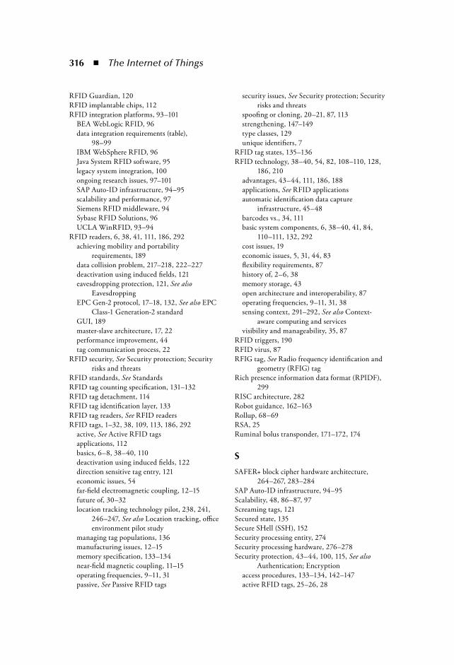
316 The Internet of Things
RFID Guardian, 120RFID implantable chips, 112RFID integration platforms, 93–101
BEA WebLogic RFID, 96data integration requirements (table),
98–99IBM WebSphere RFID, 96Java System RFID software, 95legacy system integration, 100ongoing research issues, 97–101SAP Auto-ID infrastructure, 94–95scalability and performance, 97Siemens RFID middleware, 94Sybase RFID Solutions, 96UCLA WinRFID, 93–94
RFID readers, 6, 38, 41, 111, 186, 292achieving mobility and portability
requirements, 189data collision problem, 217–218, 222–227deactivation using induced fields, 121eavesdropping protection, 121, See also
EavesdroppingEPC Gen-2 protocol, 17–18, 132, See also EPC
Class-1 Generation-2 standardGUI, 189master-slave architecture, 17, 22performance improvement, 44tag communication process, 22
RFID security, See Security protection; Security risks and threats
RFID standards, See StandardsRFID tag counting specification, 131–132RFID tag detachment, 114RFID tag identification layer, 133RFID tag readers, See RFID readersRFID tags, 1–32, 38, 109, 113, 186, 292
active, See Active RFID tagsapplications, 112basics, 6–8, 38–40, 110deactivation using induced fields, 122direction sensitive tag entry, 121economic issues, 54far-field electromagnetic coupling, 12–15future of, 30–32location tracking technology pilot, 238, 241,
246–247, See also Location tracking, office environment pilot study
managing tag populations, 136manufacturing issues, 12–15memory specification, 133–134near-field magnetic coupling, 11–15operating frequencies, 9–11, 31passive, See Passive RFID tags
security issues, See Security protection; Security risks and threats
spoofing or cloning, 20–21, 87, 113strengthening, 147–149type classes, 129unique identifiers, 7
RFID tag states, 135–136RFID technology, 38–40, 54, 82, 108–110, 128,
186, 210advantages, 43–44, 111, 186, 188applications, See RFID applicationsautomatic identification data capture
infrastructure, 45–48barcodes vs., 34, 111basic system components, 6, 38–40, 41, 84,
110–111, 132, 292cost issues, 19economic issues, 5, 31, 44, 83flexibility requirements, 87history of, 2–6, 38memory storage, 43open architecture and interoperability, 87operating frequencies, 9–11, 31, 38sensing context, 291–292, See also Context-
aware computing and servicesvisibility and manageability, 35, 87
RFID triggers, 190RFID virus, 87RFIG tag, See Radio frequency identification and
geometry (RFIG) tagRich presence information data format (RPIDF),
299RISC architecture, 282Robot guidance, 162–163Rollup, 68–69RSA, 25Ruminal bolus transponder, 171–172, 174
S
SAFER+ block cipher hardware architecture, 264–267, 283–284
SAP Auto-ID infrastructure, 94–95Scalability, 48, 86–87, 97Screaming tags, 121Secured state, 135Secure SHell (SSH), 152Security processing entity, 274Security processing hardware, 276–278Security protection, 43–44, 100, 115, See also
Authentication; Encryptionaccess procedures, 133–134, 142–147active RFID tags, 25–26, 28
Index 317
anonymous ID scheme, 116–117, 141asset and vehicle tracking RFID issues, 204blocker tags, 116Bluetooth example, 257–285, See also
Bluetooth securitychallenges, 122–123ciphers, 139cryptographic primitives, 138, See also specific
measuresdeactivation using induced fields, 121detection units, 121digital signature-based scheme, 120direction sensitive tag entry, 121EPC Gen-2 standard, analysis, 140–147EPC Gen-2 standard, improving, 147–152Faraday cage or jamming, 116hash function-based solutions, 117–119, 138,
141, See also Hash functionsHenrici and Muller’s scheme, 119inventory procedure, 140–141key management, 261–262kill command, 20, 26, 31, 116, 142layered RFID solution, 120lock command, 144–146passwords, 25policy and regulation, 120pseudonymization or minimalist cryptography,
117, 141pseudorandom number generation, 139–140,
141, 143read command, 144re-encryption, 117rewriting, 116RFID Bill of Rights, 120RFID-enabled logistics services and, 216–217RFID Guardian or firewall, 120screaming tags, 121tag locking, 25tag memory and cryptographic functionality,
149tag-to-backend server authentication, 149–150
Security risks and threats, 20–21, 87, 112–115, 217
animal RFID applications and, 182–183content falsification, 115data tempering, 114deactivation attacks, 114denial of service, 114, 138, 146, 152, 221–222eavesdropping, See EavesdroppingEPC Gen-2 standard and, 128, 140–147identity falsification, 114–115physical attacks, 113RFID viruses, 87
skimming, 147, 148tag detachment, 114tag spoofing or cloning, 20–21, 87, 113, 138,
147traffic analysis, 138viruses and worms, 182
Security trustworthiness research, 211–213Semantic Web, 297Semiactive RFID tags, 6, 8, See also Semipassive
RFID tagsSemicollision threshold, 226Semipassive RFID tags, 6, 7, 28–30, 38, 40, 129Semirandomized hash lock, 221Sensors, 24–25, 29, 44–45
battery life, 30, 31extensible sensor stream processing, 89–90GPS, 45human location tracking system, 240photosensor-based geometric context sensitive
system, 157–159RFID integration platforms and, 100system integration issues, 100
Serialized Global Location Number (GLN), 43
Serialized Global Trade Identification Number (SGTIN), 43
Serial Shipping Container Code (SSCC), 43Service delivery platform (SDP), 289Service-oriented architecture (SOA), 209,
289, 296SOA-Trust, 213–216
Session initiation protocol (SIP), 298–299, 303SHA-1, 138SHA-256, 138Short message service (SMS), 193Siemens RFID middleware, 88–89, 91, 94Single-sideband amplitude shift keying (SSB-
ASK), 133SIP, 298–299, 303Size reduction, 19Skimming attacks, 147, 148Sleep mode, 22, 27, 131–132Slice and dice, 69Slot counter, 135, 137Smart Building project, 236Smart RFID Middleware systems, 187, 193–197SOA-Trust, 216Software architecture, Internet of things and,
288–289Space utilization analysis, 235, 239Spoofing identity, 20–21, 113, 138SSH, 152SSL, 87

318 The Internet of Things
Staff tracking, See Location tracking, office environment pilot study
Standards, 10, 41–43, 128–130, See also EPC Class-1 Generation-2 standard; specific standards
active RFID tags, 21–24, 25, 39–40animal identification and monitoring,
168–170, 182Star schema, 77Stay table, 62–63Stock keeping unit (SKU), 64Stream cipher function, 263, 268–269, 282–283Structured Query Language (SQL), 87Supply chain management (SCM), 34Sybase RFID Solutions, 96Synchronous dynamic random access memory
(SDRAM), 278System on a chip (SoC) design, 25
T
Temperature monitoring, 28, 44temperature heterogeneity problem, 29–30
Thermistors, 29Time division multiple access-based (TDMA)
anti-collision algorithm, 224Timestamps, 86–87Transducer Electronic Data Sheet (TEDS), 25Transponder technology, 3, See also RFID
technologyTrie, 56Trustworthy pervasive services, 208, 211–213,
See also RFID-enabled logistics servicestrustworthy SOA, 213–216
U
Ubisense system, 236–241, See also Location tracking, office environment pilot study
Ubitags, 244, 246UCLA WinRFID, 93–94Ultra high frequency (UHF) RFID, 10–11
EPC Gen-2 standard, 131Ultrawideband radiofrequency identification
system, 239Unit key, 262Universal hash function, 138Universal Product Code (UPC), 6–7, 19,
35, 109
U.S. Department of Agriculture (USDA), 166, 177
U.S. Department of Defense (DoD), 43User agent profile (UAP), 293
V
Vehicle tracking, See Asset and vehicle trackingVerichip, 112VeriSign, 212Viruses, 87, 182Voice over IP (VoIP), 297
W
Wal-Mart, 54, 82, 83Warehouse management application, asset
tracking system, 198–202Warehouse management system (WMS), 34, 47Wavelength division multiplexed communication,
163WebLogic RFID, 96Web Ontology Language (OWL), 294Web Service Description Language (WSDL),
214, 297Web Services Trust Language (WS-Trust),
212–213WebSphere RFID, 96Wi-Fi-based active RFID, 40Wild animals, 181WinRFID, 97Wired equivalent privacy (WEP), 152Wireless Ethernet, 259Wireless Intelligent Terminal (WIT), 187, 189,
190–193Wireless LAN, 271Wireless local area network (WLAN), 190Wireless wide area network (WWAN), 191Worms, 182WSDL, 214WSDL-S, 297
X
XML, 97, 294–295
Z
Zoo animals, 181
