the isle of man code of safe working practice · pdf filecode of safe working practice for the...
TRANSCRIPT

THE ISLE OF MAN CODE OF SAFE WORKING PRACTICE
FOR THE CONSTRUCTION AND USE OF 15 METRE (LOA) TO LESS THAN
24 METRE (L) FISHING VESSELS
ISLE OF MAN MARINE ADMINISTRATION PEREGRINE HOUSE
PEEL ROAD DOUGLAS
ISLE OF MAN IM1 5EH
Telephone: 01624 688500 Facsimile: 01624 688501
Effective from 1ST APRIL 2006
1

INDEX CHAPTER 1 Sections 1. - 8 Foreword 9. Definitions 10. Application and Interpretation 11. Compliance with Code Requirements 12. Surveys, Inspections and Certification 13. Initial Surveys, Surveys for Renewal of Certificates and Surveys During Repairs 14. Inspections of Fishing Vessels 15. Issue and Form of Isle of Man Fishing Vessel Certificates 16. Duration of Certificates 17. Extension of Certificates 18. Cancellation of Certificates 19. Change of Ownership 20. Detention and Penalties 21. Certifying Authorities 22. Appeal Procedures 23. Standards for Vessels “Flagging-in” to IOM Registration 24. Transitional Arrangements on Entry into Force of the Code 25. Survey and Certification Fees 26. Updating the Code CHAPTER 2 CONSTRUCTION AND STRUCTURAL STRENGHT 27. General Requirements for Structural Strength 28. Construction Materials 29. New Vessels 30. Existing Vessels 31. Decks – Freeboard Deck 32. Decks – Weather Deck 33. Watertight Bulkhead 34. Watertight Doors WATERTIGHT AND WEATHERTIGHT INTEGRITY 35. Openings and Closing Arrangements 36. Hatchway Covers 37. Weathertight Doors 38. Heights of Hatchways Coamings and Sills to Weathertight Doors 39. Sidescuttles (Portholes) and Windows 40. Scuppers, Inlets and Discharges 41. Ventilators 42. Air Pipes WATERFREEING ARRANGEMENTS 43. General 44. Freeing Ports
2
CHAPTER 3 STABILITY AND FREEBOARD 45. General 46. Stability Criteria 47. Lightship Particulars 48. Vessel Modifications Affecting Stability 49. Lifting Operations FREEBOARD 50. Freeboard 51. Draught Marks CHAPTER 4 MACHINERY 52. General 53. Machinery Installations 54. Means for Going Ahead and Astern 55. Engine Starting 56. Air Pressure Systems 57. Propeller Shafts 58. Gearboxes 59. Propeller and Stern Gear 60. Controllable Pitch Propellers 61. Exhaust Systems 62. Cooling Water and Other Seawater Systems 63. Fuel, Lubricating and Hydraulic Systems (fire hazards) 64. Oil Fuel Installations 65. Ventilation 66. Refrigerating Plant 67. Spare Gear ELECTRICAL ARRANGEMENTS 68. General 69. Systems 70. Distribution Systems 71. Lighting 72. Hazardous Spaces 73. Reference Standards 74. Electrical Precautions 75. Equipment and Installation Requirements 76. Accumulator (Storage) Batteries 77. Emergency Power Source BILGE PUMPING 78. General 79. Bilge and Fish Processing Space Pumping Arrangements 80. Bilge Alarms
3

STEERING GEAR, RUDDERS, ANCHORS AND CHAIN CABLES 81. Steering Gear 82. Vessels Fitted with Steering Devices other than Rudders 83. Electrical and Electro-hydraulic Steering Gear 84. Anchors and Cables CHAPTER 5 FIRE PROTECTION, DETECTION AND EXTINCTION FIRE 85. General 86. Structural Fire Protection for Vessels with Hulls Constructed of Steel or other Equivalent
Material 87. Structural Fire Protection for Vessels with Hulls Constructed of Combustible Materials 88 Ventilation Systems 89. Fire Detection 90. Fire Extinction 91. Fire Extinguishing Equipment 92. Means of Escape and Emergency Exits 93. Means for Stopping Machinery MISCELLANOUS 94. Space Heaters 95. Galley Area 96. Oil Fuelled Installations (cooking ranges and heating appliances) 97. Liquefied Petroleum Gas Installations (cooking ranges and heating appliances) 98. Portable Plant 99. Storage of Flammable Liquids, Toxic Liquids, Toxic Gases and Compressed Gases 100. Cleanliness of Machinery Spaces CHAPTER 6 101. General 102. Risk Assessment 103. Precautions against falls including Bulwarks, Guard Rails and Hand Rails 104. Harnesses 105. Surface of Working Decks 106. Winches, Tackles and Hoisting Gear 107. Ventilation of Enclosed Workplaces 108. Temperature of Working Areas 109. Natural and Artificial Lighting of Workplaces 110. Workplace Soundproofing, Insulation and Cleanliness 111. Doors 112 Securing of Heavy Equipment. 113. Medical Stores
4
CHAPTER 7 LIFE SAVING APPLIANCES 114. General 115. Vessel Requirements 116. Availability, Stowage and Maintenance of Survival Craft and Life Saving Appliances 117. Embarkation into Liferafts CHAPTER 8 EMERGENCY PROCEDURES 118. Inspections 119. Drills CHAPTER 9 COMMUNCIATIONS AND NAVIGATION 120. Radio Equipment 121. Navigation Lights, Shapes and Sound Signals 122. Visibility from the Wheelhouse NAVIGATIONAL EQUIPMENT 123. Compass 124. Other Navigational Equipment 125. Nautical Publications 126. Signalling Lamp/Light for use During Search and Recovery 127. Miscellaneous Equipment. CHAPTER 10 CREW ACCOMMODATION 128. Vessel Requirements 129. Additional Requirements 130. Signs CHAPTER 11 131. Clean Seas Annex 1 – Fishing Vessel Certificate Annex 2 – Information as to Stability of Fishing Vessels
5

CHAPTER 1 (GENERAL) FOREWORD 1. This Code applies to all fishing vessels, registered in the Isle of Man of 15 metres length
overall (LOA) to less than 24 metres registered length (L) in accordance with the United Kingdoms Fishing Vessels (Safety of 15 – 24 Metre Vessels) Regulations 2002 as applied to the Isle of Man by SD73/06 The Fishing Vessel (Safety Legislation)) (Application) Order 2006 and will enter into force on 1st April 2006.
2. The Code was developed by the UK’s Maritime and Coastguard Agency who have kindly
permitted and assisted the Marine Administration in adopting and applying the Code for the Isle of Man.
3. This document is the UK Code modified to take account of local circumstances and is called
the “Isle of Man Code of Safe Working Practice for the Construction and use of 15 Metre (LOA) to less than 24 Metre (L) Fishing Vessels”. Any references to the “Code” in this document are references to the Isle of Man Code.
4. The Isle of Man Marine Administration would like to thank the MCA, Seafish, Manx Fish
Producers Organisation and those fishermen and persons from the Industry who have greatly contributed to the process of adopting the Code for the Isle of Man.
5. The provisions of the Code replace the application of the following regulations in relation to
vessels to which this Code apply:
• The Fishing Vessel (Safety Provisions) Rules 19751 as amended; (except where this Code permits vessels constructed before 1 April 2006 to continue to comply with the provisions of these Rules);
• The Fishing Vessel (Life Saving Appliances) Regulations 1988 (GC187/88) as amended;
• The Merchant Shipping (Crew Accommodation) (Fishing Vessels) Regulations 19752 as
amended; and
• The Merchant Shipping (Radio) (Fishing Vessels) Rules 19743 as amended.
1 S.I.1975 No. 330 as applied to the Isle of Man by GC75/77 2 S.I. 1975 No. 2220 as applied to the Isle of Man by GC163/81 3 S.I. 1974 No. 1919 as applied to the Isle of Man by GC75/77
6

6. The following legislation is also relevant to fishing vessels that are covered by this Code:
• SI 1972 No. 919 The Merchant Shipping (Crew Agreements, Lists of Crew and Discharge of Seamen) (Fishing Vessels) Regulations4;
• SI 1972 No. 1701 The Merchant Shipping (Seamen’s Wages and Accounts) (Fishing
Vessels) Regulations 19755;
• SI 1981 No. 570 The Merchant Shipping (Official Log Books) (Fishing Vessels) Regulations6;
• SI 1984 No. 1115 The Fishing Vessels (Certification of Deck Officers and Engineer
Officers) Regulations7;
• SD392/91 Merchant Shipping (Registration of Fishing Vessels) Regulations 1991;
• SD389/96 Merchant Shipping (Distress Signals and Prevention of Collisions) Regulations 1996;
• SD500/96 Fishing Vessels (Medical Stores) Regulations 1996;
• SD513/98 Merchant Shipping (Tonnage) Regulations 1998;
• SD865/02 Merchant Shipping (Safety of Navigation – SOLAS Chapter V) Regulations
2004;
• SD239/05 Merchant Shipping (Prevention of Air Pollution from Ships) Regulations 2005; and
• SD72/06 The Fishing Vessel (Radio) Regulations 2006.
7. In some sections within this Code, a reminder is given of the requirements of existing
regulations. In those cases the purpose of this Code is not to impose any separate regulatory requirement, but only to provide a reference to the requirements that are contained within those other regulations.
8. Where in some sections of the code there is reference to any action or standard that is
recommended, in those cases the purposes of this Code is not to impose any separate regulatory requirement.
4 As applied to the Isle of Man by GC163/81 and amended. 5 As applied to the Isle of Man by GC163/81. 6 As applied to the Isle of Man by GC163/81. 7 As applied to the Isle of Man by GC18/85 and amended.
7
DEFINITIONS 9. In this Code, except where the context indicates otherwise - “A” class divisions means those divisions formed by bulkheads and decks that are: (a) constructed of steel or other equivalent material;
(b) suitably stiffened; (c) so constructed as to be capable of preventing the passage of smoke and flame to the end
of the 60 minute fire test; and (d) so insulated where necessary with suitable non-combustible materials such that if the
division is exposed to a standard fire test, the average temperature of the unexposed side of the division will rise not more than 139 degrees centigrade above the initial temperature nor will the temperature at any one point, including any joint, rise more than 180 degrees centigrade above the initial temperature within the time listed below:
A-60 standard 60 minutes A-30 standard 3. minutes A-0 standard 0 minutes
“Accommodation spaces” means corridors and lobbies, stairways, lavatories, cabins, offices, crew spaces, pantries not containing cooking appliances and spaces similar to any of the foregoing and trunks to such spaces; “Amidships” is the mid-length of Length between Perpendiculars (LBP); “Approved” means: a) in relation to hull and machinery construction and arrangements:
approved by the Marine Administration or one of the following organisations: American Bureau of Shipping Bureau Veritas Det Norske Veritas Germanischer Lloyd Lloyd’s Register of Shipping Rigistro Italiano Navale Sea Fish Industry Authority
b) in relation to life saving appliances: approved by Marine Administration or a signatory Administration to SOLAS 1974
as amended, or, in relation to any equipment or arrangement by a Classification society;
c) in relation to stability:
approved by Marine Administration
8
“B’ class divisions” means those divisions formed by bulkheads, decks, ceilings or linings that;
a) are so constructed as to be capable of preventing the passage of flame to the end of the first 30 minutes of the standard fire test:
b) have an insulation value such that during the standard fire test the average temperature of the unexposed side will not rise more than 140 degrees centigrade above its initial temperature, nor will its temperature at any one point, including any joint, rise more than 225 degrees centigrade above its initial temperature within the time listed below:
B-15 standard 15 minutes
B-0 standard 0 minutes
“Breadth (B)” is the maximum breadth of the vessel, measured to the moulded line of the frame in a vessel with a metal shell and to the outer surface of the hull in a vessel with a shell constructed of any other material; “Code” means this Code, unless otherwise specified; “Control stations” are those spaces in which the ships radio or main navigation equipment or the emergency source of power is located, or where the fire recording or fire control equipment is centralised; “Crew” means any person carrying out an occupation on board a vessel, including trainees and apprentices but excluding shore personnel carrying out work on board a vessel at the quayside and port pilots; “Crew space” means crew accommodation and includes sleeping rooms, mess rooms, sanitary accommodation, hospital accommodation, recreation accommodation, store rooms and catering accommodation provided for the use of seamen but does not include any accommodation which is also used by or provided for the use of passengers; “Deadship condition” is the condition under which the main and auxiliary machinery are not in operation due to the absence of starting power; “Decked vessel” means a vessel with a continuous watertight freeboard deck that extends from stem to stern and has positive freeboard throughout, in any condition of loading of the vessel; “Deckhouse” or “Superstructure” means a permanent enclosed structure fitted on the freeboard or superstructure deck;
“Depth” means the moulded depth;
“Draught” means the vertical distance from the moulded base line amid-ships to the operating water line of a vessel;
9
“Enclosed superstructure” means a superstructure with:
a) enclosing bulkheads of efficient construction; b) access openings, if any, in those bulkheads fitted with permanently attached weathertight
doors of a strength equivalent to the unpierced structure that can be operated from either side; and
c) other openings in sides or ends of the superstructure fitted with efficient weathertight means of closing;
“Equivalent material” used in the expression “steel or other equivalent material” means any non-combustible material which, by itself or due to insulation provided, has structural and integrity properties equivalent to steel at the end of the applicable exposure to the standard fire test (e.g. aluminium alloy with appropriate insulation); “Existing vessel” means a fishing vessel the keel of which was laid or the construction commenced before 1st April 2006; “F” class divisions means those divisions formed by bulkheads, decks, ceilings or linings that:
a) are so constructed as to be capable of preventing the passage of flame to the end of the first 30 minutes of the standard fire test; and
b) have an insulation value such that during the standard fire test the average temperature of the unexposed side will not rise more than 139 degrees centigrade above its initial temperature, nor will the temperature at any one point, including any joint, rise more than 225 degrees centigrade above the original temperature, up to the end of the first 30 minutes of the standard fire test;
The Marine Administration may require a test of a prototype division, in accordance with the procedures detailed in the Fire Test Procedures Code, to ensure that it meets the above requirements for integrity and temperature rise; “Fire Test Procedures Code” means the IMO Code for Application of Fire Test Procedures; “Fishing vessel” has the meaning given to it by section 78 of the Merchant Shipping Registration Act 1991; (c.21) “Float-free” in relation to life saving appliances means that method whereby the appliance is automatically released from a sinking vessel and is ready for use; “Freeboard” means the distance measured vertically downwards from the upper edge of the freeboard deck to the waterline; “Freeboard deck” means the lowest complete deck above the deepest operating waterline from which fishing is undertaken. In vessels fitted with two or more complete decks, the Certifying Authority may accept a lower deck as the freeboard deck provided that the deck is situated above the deepest operating waterline; “IMO” means the International Maritime Organization;
10

“Independent” in relation to a pump, means a pump operated by power source other than from the vessel’s main engines, when electrically operated, these should work independently through a different power supply; “Isle of Man (IOM) Fishing Vessel Certificate” means a certificate issued in respect of a fishing vessel under this Code; “Length overall (LOA)”means the overall length from the foreside of the foremost fixed permanent structure to the aftside of the aftermost fixed permanent structure of the vessel; and “fixed permanent structure” –
a) includes any portion of the hull which is capable of being detached, but which is fixed in place during the normal operation of the vessel,
b) does not include functional arrangements such as safety rails, bowsprits, pulpits, stemhead fittings, rudders, steering gear, outdrives, outboard motors, propulsion machinery, diving platforms, rubbing strips and fenders, other than where such functional arrangements are designed to replace any part of the hull that has been removed;
“Length (L)”in relation to a vessel, means the registered length which –
a) is recorded as the registered length in the vessel’s certificate of registry issued under the Merchant Shipping (Registration of Fishing Vessels) Regulations 19918;
b) is recorded as the registered length in any equivalent certificate issued in the case of a vessel registered outside of the Isle of Man, or
c) would be the registered length if the vessel were a Isle of Man fishing vessel, in the case of an unregistered vessel;
“Length between perpendiculars” (LBP) is the ITC ’69 definition which means 96% of the total length on a waterline of a vessel at 85% of the least moulded depth measured from the top of the keel, or the length from the fore-side of the stem to the axis of the rudder stock on that waterline, if that be greater. In vessels designed with a rake of keel the waterline on which this is measured should be parallel to the designed waterline. The forward perpendicular and the after perpendicular are positioned at the forward and after ends of LBP respectively; “Lifebuoy” means a lifebuoy complying with the requirements of SOLAS 1974 as amended; “Lifejacket” means a lifejacket complying with the requirements of SOLAS 1974 as amended or as approved by the Marine Administration; “Liferaft” means a liferaft complying with the requirements of SOLAS 1974 as amended; “Line throwing appliance” means an appliance complying with the requirements of SOLAS 1974 as amended; “Low flame spread” means that the surface thus described will adequately restrict the spread of flame, this being determined in accordance with the IMO Fire Test Procedures Code;
8 GC392/91
11

“Machinery space” means the main engine room; “Marine Administration” means the Isle of Man Marine Administration a division of the Isle of Man Department of Trade and Industry; “MCA” means The Maritime and Coastguard Agency, an executive agency of the Department for Transport; “Moulded depth” means the vertical distance measured at the mid point of LBP from the top of the keel to the top of the freeboard deck beam at side. In wood and composite vessels the distance is measured from the lower edge of the keel rabbet. Where the form at the lower part of the midship section is of a hollow character, or where thick garboards are fitted, the distance is measured from the point where the line of the flat of the bottom continued inwards cuts the side of the keel. In vessels:
a) having rounded gunwales the moulded depth should be measured to the point of intersection of the moulded lines of the deck and side shell plating, the lines extending as though the gunwale were of angular design; and
b) where the freeboard deck is stepped and the raised part of the deck extends over the point at which the moulded depth is to be determined, the moulded depth should be measured to a line of reference extending from the lower part of the deck along a line parallel with the raised part;
“Navigable speed” means the minimum ahead speed at which the vessel can be effectively steered; “New vessel” means a fishing vessel, the keel of which was laid or the construction commenced on or after 1st April 2006; “Non-combustible material” means material that neither burns nor gives off flammable vapours in sufficient quantity for self-ignition when heated to a temperature of 750 degrees Centigrade, this being determined in accordance with the IMO Fire Test Procedures Code; “Owner” means the registered owner of a vessel, unless that vessel has been chartered by demise or is managed, either wholly or in part, by a natural or legal person other than the registered owner under the terms of a management agreement; in that case, the owner shall be construed as the demise charterer or natural or legal person managing the vessel as appropriate; “Power unit” means:
a) in the case of electric steering gear, the electric motor and its associated electrical equipment; or
b) in the case of electro-hydraulic steering gear, the electric motor, its associated electrical equipment and connected pump;
“Rocket parachute flare” means a pyrotechnic signal complying with the requirements of SOLAS 1974 as amended;
12

“Sea” in the context of ‘at sea’ means all waters outside a safe haven and “safe haven” means a harbour or shelter of any kind which affords entry, subject to prudence in the weather conditions prevailing, and protection from the forces of weather; “Self-activating smoke signal” means a signal complying with the requirements of SOLAS 1974 as amended; “Self-igniting light” means a light complying with the requirements of SOLAS 1974 as amended; “Service spaces” include galleys containing cooking appliances, lockers and store rooms, paint rooms, workshops (other than those forming part of machinery spaces) and similar spaces; “Skipper” means the crew member who commands the vessel or has responsibility for it; “SOLAS 1974 as amended” means the International Convention for the Safety of Life at Sea, 1974, as amended; “Standard fire test” is a test in which a specimen of the relevant bulkhead or deck is exposed in a test furnace to temperatures corresponding approximately to a standard time temperature curve in accordance with the IMO Fire Test Procedures Code; “Standards” such as BS (British Standard), EN (European Standard accepted by the European Committee for Standardisation, CEN), IEC (International Electrotechnical Commission) and ISO (International Organisation for Standardisation) identified in the Code for reference purposes, should include any standards that amend or replace them; “Superstructure” or “Deckhouse” means a permanent enclosed structure fitted on the freeboard or superstructure deck; “Superstructure deck” means that complete or partial deck or the top of a superstructure, deckhouse or other erection situated at a height of more than 1.8 metres above the freeboard deck; “Survival craft” means a craft capable of sustaining the lives of persons in distress from the time of abandoning the vessel; “Vessel” means a new or existing fishing vessel; “Watertight” in relation to a structure means capable of preventing the passage of water through the structure in any direction under a head of water for which the surrounding structure is designed; “Weather deck” means the main deck that is exposed to the elements; “Weathertight” means that in any sea conditions water will not penetrate into the vessel.
13

APPLICATION AND INTERPRETATION 10 Application 10.1 The Code applies to all fishing vessels, registered in the Isle of Man under Part III of the
Merchant Shipping Registration Act 1991 c.15 , of 15 metres in length overall to less than 24 metres registered length and will enter into force on 1st April 2006.
10.2 It is recognised that in a number of areas it would be impractical for existing vessels to comply fully with the new provisions for construction and permanently fitted equipment. Alternative arrangements or provisions for existing vessels are identified individually for each section or paragraph affected. E
10.3 With reference to section 10.2, owners of existing vessels may, and are recommended to, comply with the Code as it applies to new vessels, instead of complying with the alternative arrangements or provisions identified in the Code for existing vessels. E
10.4 Exemptions previously granted to vessels under the provisions of the Fishing Vessels (Safety Provisions) Rules 1975, as amended, will continue to apply and be recorded on the certificate unless otherwise required in the Code. The conditions associated with those exemptions are individual vessel provisions and need to be met for compliance with the Code. E
10.5 The application of the Code to new and existing vessels is indicated within the body of the text by means of the following convention:
a) Normal text: section is applicable to new and existing vessels;
b) Text in italics, N at right margin: section is applicable to new vessels only;
c) Text in bold format, E at right margin: section is applicable to existing vessels only
10.6 Where any provision of the Code is expressed in the conditional (i.e. “should”) then this provision shall be a requirement.
10.7 Where a provision in this Code requires equipment, machinery, an arrangement or any other thing to be “to the satisfaction of the Marine Administration”, this means that the Marine Administration is to determine whether the equipment or machinery etc is suitable for its purpose and satisfies the requirements of this Code.
14

11. Compliance with Code Requirements To comply with the Code the vessel owner is responsible for ensuring that the vessel:
a) is built, equipped, surveyed, certified and maintained and operated in accordance with the relevant provisions of the Code;
b) continues to comply with the requirements of the Code in service;
c) is operated by appropriately qualified and certificated crew who have completed mandatory training courses; and
d) is not operated as a fishing vessel without a valid IOM fishing vessel certificate being in force.
12. Surveys, Inspections and Certification 12.1 Every vessel should be surveyed and inspected in accordance with the requirements of this
Section:
a) an initial survey during and on completion of construction, or on transfer to the IOM register prior to the issue of a IOM Fishing Vessel Certificate;
b) certificate renewal surveys at intervals not exceeding 5 years;
c) an intermediate inspection in accordance with section 14 below;
d) surveys during major repairs or modifications;
12.2 Applications for survey or inspection should be made by or on behalf of the owner of the
vessel to the Marine Administration giving reasonable notice, for the survey or inspection to be carried out, at the port agreed with the Marine Administration.
12.3 A vessel may be examined by the Marine Administration at any time to verify compliance
with Code requirements. 13. Initial Surveys, Surveys for Renewal of Certificates and Surveys during Repairs 13.1 A surveyor appointed by the Marine Administration should survey the vessel in order to
verify that the vessel complies with the requirements of the Code and such regulations as may apply to it. The surveyor may require the vessel and any of its machinery, fittings, equipment or arrangements to be submitted to such tests and examinations as are considered necessary to demonstrate compliance with the requirements of the Code and applicable legislation.
13.2 On completion of the survey, the surveyor should provide a declaration of survey and a
record of particulars. 13.3 Two copies of the record of particulars should be sent to the owner of the vessel on
completion of survey, one copy of which should be placed on board for inspection at subsequent surveys.
15

13.4 Modifications or alterations to the vessel’s structure and/or the removal or repositioning of any equipment as detailed in the Record of Particulars and Equipments, changes in the vessel’s mode of fishing and/or its gear to other than those habitually employed, and the fitting of additional equipment should be investigated prior to making any changes, to ensure that the vessel will continue to comply with the required stability criteria. In addition, such modifications or alterations should only be carried out after the skipper or owner has notified the Marine Administration in writing and obtained their approval. No charge shall be made by the Marine Administration for undertaking any work in relation to this or for providing any approval in accordance with this section.
13.5 When extensive repairs, modifications or alterations are carried out on an existing
vessel, then any such work should comply with the requirements of this Code as are applicable to a new vessel, and be to the satisfaction of the Marine Administration. E
13.6 Modifications or alterations made to a vessel without informing and obtaining approval from
the Marine Administration shall have the effect of making the vessel non-Code compliant. A vessel shall then be subject to a full survey by the Marine Administration to determine whether or not the vessel remains Code compliant and in a safe condition to go to sea.
13.7 Where an inspection is required by the Marine Administration as a result of unauthorised
modifications fees may be charged to the owner in accordance with the Marine Administration’s fee regulations applicable at the time.
14. Inspections of Fishing Vessels 14.1 Every vessel having a valid IOM Fishing Vessel Certificate should be inspected not less
than 27 months and not more than 33 months from the recorded date of the vessel’s initial or previous renewal survey, by a surveyor of the Marine Administration. The inspection should verify that the vessel continues to comply with the requirements of the Code.
14.2 When a satisfactory inspection has been carried out, the surveyor should endorse the Fishing
Vessel Certificate accordingly. CERTIFICATION 15. Issue and form of Isle of Man Fishing Vessel Certificates
If the Marine Administration is satisfied that a vessel has been duly surveyed in accordance with the provisions of this Code and is found to comply with the requirements of the Code and other relevant regulations, an Isle of Man Fishing Vessel Certificate in the format set out in Annex 1 or other such format as may be specified by the Marine Administration will be issued by the Marine Administration to the owner of the vessel.
16. Duration of certificates
An Isle of Man Fishing Vessel Certificate may remain in force for 5 years from the date of its issue or such shorter period as may be specified by the Marine Administration, unless extended or cancelled under sections 17 or 18 respectively.
16

17. Extension of certificates 17.1 The Marine Administration may, in exceptional circumstances, extend the validity of an
IOM Fishing Vessel Certificate for a period not exceeding two months. 17.2 Subsequent Fishing Vessel Certificates should be dated to correspond with the original
Fishing Vessel Certificate before such an extension. 18. Cancellation of certificates The Marine Administration may cancel an IOM Fishing Vessel Certificate if satisfied that:
a) any declaration of survey on which the certificate was founded has been in any particular made fraudulently or erroneously;
b) the certificate has been issued based upon false or erroneous information;
c) since the issue of the certificate, the hull, equipment or machinery have sustained any damage or are otherwise inadequate for their intended service;
d) the vessel has been modified or altered to the extent described in section 13.4 without due notification or approval as required by that section;
e) the certificate has not been endorsed in the manner set out in section 14;
f) another Fishing Vessel Certificate has been issued in respect of the vessel;
g) the vessel has ceased to be registered as a fishing vessel in the Isle of Man;
h) or a vessel classed with a Classification Society is not maintained in Class.
19. Change of Ownership
Risk assessments of the vessel are particular to each owner. When a vessel is sold, the new owner must complete, or arrange for the completion of, a new risk assessment.
20. Detention and Penalties
A vessel that is found, in the course of inspection, or survey, not to have been equipped, maintained, assessed in accordance with the Code will be liable to detention under The Fishing Vessels (Safety of 15 – 24 Metre Vessels) Regulations 2001 as applied to the Isle of Man by SD73/06 The Fishing Vessel (Safety Legislation ) (Application) Order 2006. An owner who operates a vessel that does not comply with the Code, or who makes a false declaration, may be liable to prosecution. A skipper who fails to operate the vessel in accordance with the requirements of the Code may be liable to prosecution.
17

21. Certifying Authorities
The Marine Administration is the Certifying Authority. However, other organisations that are so authorised by Marine Administration may appoint persons for the purpose of surveying vessels for ascertaining compliance with Code provisions for hull construction, machinery installations, watertight integrity, openings, pipework, bilge pumping, anchors, radio equipment, cables and electrical installations.
22. Appeal Procedures 22.1 If an owner is dissatisfied with the results of a survey or inspection, or the issue of a
certificate has been refused, or for any other reason and agreement cannot be reached with the attending surveyor, the owner may refer the matter to the Principal Marine Surveyor (Fishing Vessels) at the Marine Administration.
22.2 Should the above procedure fail to resolve the dispute, the owner may refer the matter to the
Director of the Marine Administration. 22.3 If an owner is still not content with the way in which the dispute has been handled, the
owner may serve notice, within twenty-one days of the completion of the procedure given in section 22.2, on the Marine Administration that their dispute be referred to a single arbitrator appointed by agreement between Marine Administration and the owner.
22.4 A person should not be qualified for appointment as an arbitrator unless that person is:
a) a person holding a certificate of competency as a deck officer, marine engineer or equivalent;
b) a naval architect;
c) a person with special experience of the fishing industry;
d) a member of the Chartered Institute of Arbitrators; or
e) a person holding a Certificate of Competency (Fishing Vessels) Class 1.
22.5 The final allocation of costs will depend on the arbitrator’s decision. If the decision is in the
favour of the owner, the arbitrator may award the owner such compensation as the arbitrator thinks fit in addition to allocating costs.
18

23. Standards for Vessels “Flagging-in” to IOM Registration 23.1 New vessels should comply with the provisions of the Code wherever the place of
construction or origin. N 23.2 Before applying to register an existing vessel in the IOM, owners are advised to
consider the consequences of compliance with the Code. Owners are recommended to seek early advice from their technical consultants and the Marine Administration prior to making any commitment for registering a vessel that has not been constructed under the survey of a Classification Society or other organisation with delegated powers granted by a Marine Administration. E
24 Transitional Arrangements on Entry into Force of the Code 24.1 The Code will come into effect 1st April 2006. After the 1st April 2006 all Fishing
Vessel Certificates issued against the Fishing Vessel (Safety Provisions) Rules 19759 shall cease to be valid. However, exemption certificates issued against the Fishing Vessel (Safety Provisions) Rules 1975 10 shall remain valid. E
24.2 It is the responsibility of the owner of any fishing vessel to which this Code applies to
contact the Marine Administration in good time before the 1st April 2006 to arrange for an inspection to be undertaken. The inspection shall verify that any additional equipment required by the Code has been provided and the vessel is in good working order. Following completion of a satisfactory inspection the Administration shall issue a Code Certificate which shall be valid until the expiry date of the vessels existing Fishing Vessel Certificate plus 1 year. This will bring the vessel into line with the Code’s 5 yearly survey and certification regime. E
24.3 The Fishing Vessel (Radio) Regulations 2006 (SD73/06) also come into effect 1st April
2006 and replace the Merchant Shipping (Fishing Vessel) (Radio) Rules 197411. Vessels must comply with the requirements of the Fishing Vessel (Radio) Regulations 2006 and be surveyed by an organisation acceptable to the Administration before a Code Certificate can be issued. E
25. Survey and Certification Fees 25.1 In order to facilitate the transition from the Fishing Vessel (Safety Provisions) Rules
1975 to the new Code the Marine Administration will undertake the first inspection and issue of certificates for existing vessels against this Code without charge. E
25.2 The Marine Administration will also meet the cost of the first Radio Survey for
existing vessels undertaken against the new Fishing Vessel (Radio) Regulations 2006. There is no separate certificate issued for compliance with the requirements of the Radio Regulations as this is included in the main Code Certificate. E
9 S.I. 1975 No. 330 as applied to the Isle of Man by GC75/77 10 S.I. 1975 No. 330 as applied to the Isle of Man by GC75/77 11 S.I. 1974 No. 1919 as applied to the Isle of Man by GC75/77
19

25.3 Where the first survey of an existing vessel finds that a vessel is not Code compliant any follow up work or subsequent surveys required shall be undertaken at the expense of the owner of the vessel in accordance with the current Fees Regulations. E
26. Updating the Code 26.1 In cases where a question of interpretation of part of the Code arises, or guidance is required
on the standards to be applied for compliance, advice may be obtained on written application to the Marine Administration or by calling 01624 688500.
26.2 The Code provisions will be reviewed and reconsidered not later than five years following
its entry into force to take into account experience gained from its application. The Marine Administration will consult and consider recommendations from the Fishing Industry.
26.3 The Marine Administration will also consider and consult with the Manx Fishing Industry
on any subsequent changes made to the original UK Code upon which this is based made by the UK’s Maritime and Coastguard Agency.
20

CHAPTER 2 CONSTRUCTION AND STRUCTURAL STRENGTH 27. General Requirements for Structural Strength 27.1 The structural strength and construction of every fishing vessel and the disposition of
bulkheads should be adequate for all foreseeable operating conditions in service. The scantlings, arrangements and construction for the hull, bulkheads, superstructures, deckhouses, machinery casings, companionways and other structures should be sufficient to withstand all operational loads arising during the vessel’s service and should be to the satisfaction of the Marine Administration.
27.2 The owners are to inform the Marine Administration if the vessel is to be operated in areas
subject to sea ice conditions. Hull construction and stability requirements will be specially considered for vessels operating in such areas.
28. Construction Materials 28.1 A vessel may be constructed of wood, fibre reinforced plastic (FRP), aluminium alloy or
steel or appropriate combinations of such materials. N
28.2 Proposals to use any other construction material should be submitted to the Marine
Administration for consideration and approval. N 29. New Vessels 29.1 Hull construction and arrangement drawings should be reviewed and approved by the
Marine Administration. N 29.2 The hull should be surveyed during construction by the Marine Administration to verify
compliance with the approved drawings. An appropriate certificate of construction should be issued on completion of build. N
30. Existing Vessels An existing vessel will be considered to be of acceptable structural strength if it is an Isle of Man registered fishing vessel and the Certifying Authority has determined that it is in a good state of repair for the purposes of this Code. E 31. Decks - Freeboard deck 31.1 The freeboard deck should be of watertight construction and should extend from stem to
stern with positive freeboard throughout in any condition of loading of the vessel. 31.2 The freeboard deck may be stepped, recessed or raised provided the stepped, recessed or
raised portion is of watertight construction. 31.3 Minimum requirements for freeboard are given in section 50. N
21
32. Decks – Weather Deck
The weather deck may be the freeboard deck or other watertight deck above that is exposed to the weather.
33. Watertight Bulkheads 33.1 Vessels should be provided with a watertight collision bulkhead in the fore part of the vessel
positioned to the satisfaction of the Certifying Authority. N 33.2 The bulkhead arrangement of an existing vessel is acceptable provided that such
arrangement continues to remain efficient in service. E 33.3 The main and auxiliary machinery essential for the propulsion and safety of the vessel
should be situated in a watertight machinery compartment with watertight bulkheads provided at the fore and aft positions of that space. N
33.4 Such bulkheads should extend up to the freeboard deck and the number of openings fitted
therein should be the minimum compatible with the safe operational requirements of the vessel. N
33.5 The strength of the bulkheads should be adequate to withstand a head of water to the
satisfaction of the Marine Administration. N 33.6 In vessels constructed of wood, a collision bulkhead and bulkheads at the fore and aft ends
of the machinery space, should be provided. The after bulkhead of the machinery space may terminate on a horizontal, flat that extends aft to the stern, above the line of shafting. The bulkheads and flat referred to in this section should be of adequate strength and gasketted and/or caulked to prevent significant leaks or flooding. N
33.7 When it is necessary for pipes, cables, etc. to penetrate watertight bulkheads, arrangements
should be made to maintain the watertight integrity of the bulkhead in way of such penetrations. The collision bulkhead should have valves fitted to all pipe penetrations and these should be capable of operation from a readily accessible position. N
33.8 A door fitted in a watertight bulkhead should be of watertight construction and be kept
closed at sea. N 33.9 Doors are not permitted in the collision bulkhead unless fitted in a bulkhead extension
above the freeboard deck, such doors may be of weathertight construction and should be kept closed at sea. N
34. Watertight Doors 34.1 The number of doors fitted in any watertight bulkhead should be the minimum compatible
with the normal operation of the ship. Every such door should be efficiently constructed and be watertight when closed.
22

34.2 Doors of hinged or sliding type may be used except that doors of the hinged type will only be allowed when there is no operational requirement for the door to be kept open at sea, such doors should be operable from both sides. Sliding type doors should be operable from an accessible position above the freeboard deck.
34.3 All doors should be capable of being efficiently operated when the vessel is listed up to 15
degrees either way. WATERTIGHT AND WEATHERTIGHT INTEGRITY 35. Openings and Closing Arrangements 35.1 The number of openings in the watertight structure of the vessel should be the minimum
consistent with its safe and practical operation and, when fitted such openings should be provided with effective closing arrangements in accordance the requirements of this Code.
35.2 Hatches and doorways which may be open at sea, should normally be arranged as near as
practicable to the vessel’s centreline. Due consideration should be given to the risk of down flooding. N
35.3 Particular attention should be paid to ensure that accesses and openings to machinery spaces
are protected by strong and efficient structures which should contain weathertight or watertight means of closure, dependent on the position of the opening.
35.4 Vessels with a wheelhouse fitted directly on the freeboard deck should be provided with a
suitable means of closure to any freeboard deck opening within the wheelhouse space. Additionally the means of drainage of the wheelhouse space should preferably be directly overboard. N
35.6 Openings in the freeboard or exposed weather decks should be properly framed and
efficiently enclosed by either superstructures, casings of adequate strength or hatch covers meeting the requirements of section 36.
35.7 Coaming heights appropriate to the position of the openings should be provided as in section
38. 35.8 Openings in weathertight boundaries for warps or wires used in fishing operations should
be kept as small as practicable and should not be submerged with a vessel heel of up to 40 degrees. N
23

36. Hatchway Covers 36.1 A hatchway that gives access to spaces below the freeboard deck should be of efficient
construction and be provided with effective means of weathertight closure. 36.2 A coaming height appropriate to the position of the hatch opening should be provided as in
section 38. 36.3 A cover to a hatchway may be of hinged, rolling or sliding type and should be permanently
secured to the structure of the vessel. Every such cover should be fitted with gaskets and clamping devices, or other equally effective means that are both sufficient to retain the cover in position and ensure weathertight integrity when closed. Discharge hatches that are not open at sea may be of the “lift-off” type, provided they are weathertight when closed. N
36.4 For new vessels the covers should be of steel or equivalent material and of sufficient
strength to accommodate the expected service loading. N 36.5 The covers provided on an existing vessel will be acceptable provided they continue to
remain efficient in service. E 36.6 Weathertight hatches on exposed freeboard and superstructure decks should be kept closed
at sea, when not in use. 37. Weathertight Doors 37.1 All access openings in the external bulkheads of enclosed superstructures and other outer
structures protecting openings in the freeboard deck should be fitted with doors of steel or other equivalent material. These doors should be permanently and strongly attached to the bulkhead and so framed, stiffened and fitted that the whole structure of which they are part, is of equivalent strength to the unpierced bulkhead and weathertight when closed. The means for securing these doors weathertight should consist of gaskets and clamping devices or other equivalent means, permanently attached to the bulkhead or to the doors themselves and arranged so that they may be operated easily and rapidly from each side of the bulkhead.
37.2 A coaming height appropriate to the position of the door should be provided as in section
38. 37.3 Weathertight doors on the freeboard deck should normally be kept closed at sea.
24

38. Heights of Hatchway Coamings and Sills to Weathertight Doors 38.1 Subject to section 38.2, every hatchway and door sill on the exposed freeboard deck should
have a coaming of substantial construction and the height of the coaming above the deck should not be less than 460 millimetres. On exposed first tier superstructure decks the height of the coamings should not be less than 100 millimetres. N
38.2 The height of the hatch coamings specified in section 38.1 may be reduced, or the coamings
omitted, provided the safety of the vessel is not thereby impaired and provided that watertight covers are fitted. Such covers should be kept as small as reasonably practicable, be permanently attached by hinges or equivalent means and capable of being rapidly closed watertight. N
38.3 Coamings may also be reduced or omitted for hatches that are provided on freeboard decks
when the hatchway is positioned within a shelter, superstructure or deckhouse provided that such spaces are maintained weathertight whilst at sea and providing that flooding hazards will not arise due to activities within those spaces. N
38.4 The heights of sills to doors provided in exposed companionways, superstructures, deckhouses and machinery casings that give access to spaces leading below the freeboard deck should not be less than those specified for hatchway coamings in section 38.1 for a similar position. For other spaces the heights of door sills may be reduced provided:
a) there is no access to spaces leading below the freeboard deck; and
b) the spaces are small; and
c) provided the safety of the vessel is not thereby impaired. N 38.5 The heights of coamings or sills may be required to be increased when a freeboard of less
than that required by section 50 has been accepted. N 38.6 Flush type deck scuttles, hatches or manholes may be fitted to exposed freeboard or
superstructure decks provided they are of watertight construction, are closed at sea and are permanently attached to the hull. N
38.7 The coaming heights for doors and hatches on existing vessels should be maintained in
accordance with the requirements of The Fishing Vessels (Safety Provisions) Rules 197512. E
12 S.I. 1975 No. 330 as applied to the Isle of Man by GC75/77
25

39 Sidescuttles (Portholes) and Windows 39.1 Side scuttles to spaces below the freeboard deck and to enclosed superstructures,
deckhouses or companionways on the freeboard deck should be fitted with hinged deadlights capable of being closed watertight. E
39.2 Every side scuttle should be fitted in a position such that its sill is above a line drawn
parallel to the freeboard deck at side having its lowest point 1 metre above the highest load waterline.
39.3 Side scuttles liable to damage from fishing gear or equipment should be suitably protected. 39.4 Side scuttles, glasses and deadlights should meet the requirements of ISO 1095, ISO 1751
and ISO 5780, type B (medium duty grade), in respect of nominal size and toughened safety glass thickness, or an equivalent standard.
39.5 Side scuttles fitted in exposed areas and in the forward bulkheads of freeboard deck
erections should be of the non-opening type. 39.6 Windows should not be fitted below the freeboard deck. 39.7 If windows are fitted in the forward or after bulkheads of exposed freeboard deck erections,
they should be provided with efficient means of protection. 39.8 Windows and their frames should meet the requirements of ISO 3903, ISO 3254 and ISO
5779, type E (heavy duty grade), in respect of nominal size and toughened safety glass thickness, or an equivalent standard. Existing arrangements for window frames will continue to be acceptable.
39.9 Wheelhouse windows should not be fabricated using polarised or tinted glass, although
portable tinted screens may be employed if desired. Wheel house windows should be made of clear toughened safety glass. Tinted glass should not be used. Tinted screens or hinged visors may be used provided they are hinged or removable.
40. Scuppers, Inlets and Discharges 40.1 The number of inlets and discharges should be kept to the operational minimum. N 40.2 Each scupper or discharge leading through the hull from spaces below the freeboard deck
or from within an enclosed superstructure or deckhouse on the freeboard deck should have an automatic non-return valve fitted at the hull with a positive means of closure from an accessible position. N
40.3 Each sea inlet valve should be fitted with a positive means of closure from an accessible
position. N 40.4 In machinery spaces, controls for main and auxiliary sea inlets essential for the operation of
machinery may be controlled locally. The controls should be readily accessible, above the floor plates, and be provided with indicators showing whether the valves are open or closed. N
26

40.5 If valves are not fitted above the floor plates, rapid and practical means should be
provided to allow for the valve to be operated from floor plate level. E 40.6 Soil and other waste water drainage should be so arranged and fitted with such water seals,
air vents and storm valves as are necessary to prevent siphoning, blowback or ingress of water. The hull closing arrangements should be as detailed in section 40.2. N
40.7 If scuppers from open decks penetrate the hull below the freeboard deck they should be
made from piping of substantial thickness. 40.8 Refer also to sections 62 (Seawater Systems), 79.10 and 79.11 (Bilge Systems) and 131
(Pollution). 40.9 Existing vessel arrangements will continue to be acceptable provided that valves fitted
at hull penetrations remain both accessible and efficient in service. E 41 Ventilators 41.1 The minimum height above deck of ventilators, other than machinery space ventilators,
should be 760 millimetres on an exposed freeboard deck, and 450 millimetres on an exposed first tier superstructure deck.
41.2 Machinery space ventilators should be led as high as is reasonable and practicable and
preferably be fitted well inboard, the angle of initial downflooding to the machinery spaces should not be less than 40 degrees. N
41.3 All ventilators should be of substantial construction and be provided with permanently
attached means of weathertight closure except that weathertight closing appliances need not be fitted to ventilators with coamings extending more than 4.5 metres above the freeboard deck or more than 2.3 metres above the superstructure deck. Fireflaps should be fitted in such coamings in accordance with section 88 (Ventilation Systems).
41.4 Refer also to sections 65 (Ventilation), 88 (Ventilation Systems), 93 (Means for Stopping
Machinery), 97.8 (Mechanical Ventilation), 99.2 (Ventilation of Hazardous Compartments), 107 (Ventilation of Enclosed Workplaces), 128.2, 128.4 and 128.7 (Ventilation of Crew Accommodation).
42. Air Pipes 42.1 The lowest point at which water might gain access through an air pipe should be not less
than 760 millimetres above the exposed freeboard deck nor less than 450 millimetres above the exposed superstructure deck. The exposed portions of the air pipes should be of substantial construction.
42.2 A reduced height may be accepted if it can be shown that the rule air pipe height would
interfere with essential vessel operations and provided that an adequate height above the deck is maintained. Alternatively consideration may be given to relocating the air pipe inboard.
27

42.3 Air pipes should be provided with an efficient means of weathertight closure and provision should be made to prevent overpressure or vacuum occurring when the tanks are being filled or emptied.
42.4 Refer also to sections 64.3, 64.5, 64.7 - 9 and 96.2 & 96. 3 (Air Pipes to Fuel Tanks). WATER FREEING ARRANGEMENTS 43 General 43.1 When freeboard or first tier superstructure decks are fitted with bulwarks, deck houses,
erections or other arrangements such that wells are formed and shipped water may be retained onboard, then ample provision should be made for rapidly freeing the decks of this water and for draining them.
43.2 The means by which this water is freed may be by freeing ports, open rails, scuppers or
other suitable arrangement. 43.3 In a vessel in which freeing ports cannot be fitted, other efficient means of clearing trapped
water from the vessel should be provided to the satisfaction of the Marine Administration. 44. Freeing Ports 44.1 Where bulwarks on weather parts of the working deck form wells, the minimum freeing port
area (A) in square metres, on each side of the vessel for each well on the working deck should be determined in relation to the length (l) and height of bulwark in the well as follows:
a) A= K x l (l need not be taken as greater than 0.7 L). Where K = 0.07 for vessels of 24 metres in length K = 0.035 for vessels of 12 metres in length L = registered length of vessel
The value of K should be obtained by linear interpolation from between the two values of lengths given above.
b) Where the bulwark is more than 1200 millimetres in average height the required
area should be increased by 0.004 square metres per metre of length of well for each 100 millimetres difference in height.
(c) Where the bulwark is less than 900 millimetres in average height, the required area
may be decreased by 0.004 square metres per metre of length of well for each 100 millimetres difference in height. N
44.2 The freeing port area calculated according to section 44.1 should be increased where the
Marine Administration considers that the vessel’s sheer is not sufficient to ensure that the deck is rapidly and effectively freed of water. N
28
44.3 Subject to the approval of the Marine Administration the minimum freeing port area for
each well on the superstructure deck should be not less than one-half the area (A) given in section 44.1. N
44.4 Freeing ports should be so arranged along the length of bulwarks as to ensure that the deck
is freed of water most rapidly and effectively. Lower edges of freeing ports should be as near the deck as practicable.
44.5 Poundboards and means for stowage of the fishing gear should be arranged so that the
effectiveness of freeing ports will not be impaired. Poundboards should be so constructed that they can be locked in position when in use and should not hamper the discharge of shipped water.
44.6 Freeing ports over 300 millimetres in depth and length greater than 450 millimetres should
be fitted with bars spaced not more than 230 millimetres nor less than 150 millimetres apart or provided with other suitable protective arrangements. Freeing port covers, if fitted, should be of suitable construction. If devices are considered necessary for locking freeing port covers during fishing operations they should be arranged to the satisfaction of the Marine Administration and easily operable from a readily accessible position. N
44.7 In vessels intended to operate in areas subject to icing, covers and protective arrangements
for freeing ports should be capable of being easily removed to restrict ice accretion. The size of openings and means provided for removal of these protective arrangements should be to the satisfaction of the Certifying Authority.
44.8 If deck erections within a well limit the volume of water that may be retained onboard then
the freeing port area may be reduced proportionally provided that such erections do not in themselves contribute to water retention. N
44.9 On existing vessels the areas of freeing ports and their arrangements will continue to
be accepted provided that such arrangements continue to remain efficient in service. E
29

CHAPTER 3 (STABILITY AND FREEBOARD) STABILITY 45. General 45.1 All vessels should be provided with approved stability information to the satisfaction of the
Marine Administration for the conditions of service for which the vessel is intended. 45.2 The approved stability information should contain the information and particulars that are
detailed in Annex 2. 45.3 Existing vessels, for which satisfactory stability characteristics have been
demonstrated by means of roll testing, should carry the results of the most recent roll test onboard in lieu of the approved stability information that is required by section 45.1. + 45.2 E
45.4 All vessels should be sufficiently stable when intact in the conditions of service for which
they are intended. 45.5 The skipper should take the precautionary measures necessary to maintain adequate stability
of the vessel. In particular, the skipper should ensure that all catch is efficiently stowed at all stages of loading to prevent the possibility of cargo shift due to vessel motions.
45.6 Information on the vessel’s stability should be available on board and accessible to those on
watch. 45.7 Instructions supplied concerning the vessel’s stability should be strictly observed by those
on watch. 46. Stability Criteria 46.1 Vessels should, for the operating conditions and circumstances set out in Annex 2 including
icing allowances when applicable, and in all foreseeable operating conditions, satisfy the following stability criteria after due correction for the free surface effects of liquids in tanks:
a) the area under the curve of righting levers (GZ curve) should not be less than:
i.0.055 metre-radians up to an angle of 30 degrees;
ii.0.090 metre-radians up to an angle of 40 degrees or such lesser angle of heel at which the lower edges of any openings in the hull, superstructures, deckhouses or companionways, being openings that cannot be closed weathertight, are immersed;
iii.0.030 metre-radians between the angles of heel of 30 degrees and 40 degrees or such lesser angle as defined in (ii) above;
b) the righting lever (GZ) should be at least 200 millimetres at an angle of heel equal to or greater than 30 degrees;
c) the maximum righting lever (GZ) should occur at an angle of heel not less than 25 degrees;
30

d) in the upright position the transverse metacentric height (GM) should not be less than 350 millimetres;
46.2 For vessels engaged on single or twin boom fishing the values of dynamic stability, righting
lever and metacentric height given in sections 46.1(a), (c) and (d) respectively should be increased by 20%.
47. Lightship Particulars 47.1 The vessel’s lightship particulars should be determined by inclining on completion of
building to the satisfaction of the Certifying Authority. N 47.2 The vessels lightship details should be verified at certificate renewal to the satisfaction of
the Marine Administration. 47.3 The carriage of unnecessary spare gear, stores and parts, the accumulation of debris and the
cumulative effects of minor modifications over time can adversely affect the vessel’s lightship weight and centre of gravity. Attention should be made to limiting these effects if lightship growth and the possibility of adverse effects on the vessel’s stability are to be avoided.
48. Vessel Modifications Affecting Stability 48.1 Modifications or alterations to the vessel’s structure and/or the removal or repositioning of
any equipment as detailed in the Record of Particulars and Equipments, changes in the vessel’s mode of fishing and/or its gear to other than those habitually employed, and the fitting of additional equipment should be investigated prior to making any changes, to ensure that the vessel will continue to comply with the required stability criteria. In addition such modifications or alterations should only be carried out after the skipper or owner has notified the Marine Administration in writing and obtained their approval. No charge shall be made by the Marine Administration for undertaking any work in relation to this or for providing any approval in accordance with this section.
49. Lifting Operations 49.1 Particular care should be taken to ensure that the vessel retains adequate stability at all times
during the course of any lifting operation. 49.2 For vessels with lifting equipment, a sketch of the rig (arrangement, length of derricks and
weight of gear) that is provided onboard should be appended to the vessel’s Trim and Stability Manual. N
49.3 The Trim and Stability Manual should also include a calculation that indicates the
maximum theoretical heel angle that will be produced when the fishing gear, excluding catch, is statically deployed on one side of the vessel, with both derricks at their maximum outreach. This is intended to provide a reference throughout the vessel’s working life. The calculation should be carried out for the vessel in the ‘arrive fishing grounds’ condition. N
31

FREEBOARD 50.1 Every vessel should be so designed, constructed and operated as to ensure that in all
foreseeable operating conditions the freeboard will be adequate to provide:
a) compliance with the stability criteria set out in this section;
b) appropriate safety for the crew working on deck;
c) appropriate safety to the vessel from the entry of water into enclosed spaces having regard to the closing appliances fitted.
502 The minimum freeboard at any point along the freeboard deck (Hmin) should be not less
than: Hmin = LBP/40 (where LBP is length between perpendiculars) N 50.3 The minimum freeboard criteria should be checked at the time of initial build, flag in or
after substantial modifications have been made to the vessel. At renewal survey the minimum freeboard should be not less than that required to comply with the stability criteria or 300 millimetres, whichever is greater. N
50.4 Where a vessel is fitted with bulwarks of at least 1 metre high, extending at least 0.15L abaft
the forward perpendicular, the minimum bow height of the freeboard deck above the deepest operational waterline at the forward perpendicular (Hfmin) should be not less than:
Hfmin = 0.75 + 6.6LBP/240 N 50.5 Where the bulwark height is less than 1 metre, the minimum bow height should be increased
accordingly. N 50.6 Hfmin may, in cases where a weathertight forecastle is fitted that extends at least 0.07LBP
abaft the forward perpendicular, be measured to the top of the forecastle deck plating. N 50.7 The minimum freeboard aft (measured at the after perpendicular) (Hamin) should not be less
than: Hamin = 0.24 + LBP/37.5 N 50.8 For vessels with shelters, that do not meet the minimum freeboard requirement, then such
shelters should be of weathertight construction up to the next deck level (i.e. with weathertight doors and hatches, no permanent openings or freeing ports but with suitable drainage being provided). N
50.9 Additionally for vessels with particular modes of operation, in which the application of the
above minimum freeboard criteria are considered to be unrealistic, then the arrangements may be specially considered and accepted by the Marine Administration provided that equivalent safety is maintained. N
32

50.10 In such circumstances the coaming heights of doors, hatches, ventilators and air pipes would need to be raised above the rule minimum by an amount equivalent to the freeboard deficiency. N
50.11 The freeboards on existing vessels will continue to be accepted providing they are
maintained in accordance with The Fishing Vessels (Safety Provisions) Rules 197513. E 51. Draught Marks 51.1 Every vessel should have scales of draughts permanently and clearly marked in metric units
on the sides of the vessel at the bow and where they can be easily read at the stern. 51.2 The datum and longitudinal positioning of the draught marks should be indicated where
appropriate by means of sketches in the vessels trim and stability manual, similarly the position of the datum for the vessel’s hydrostatics data should be correlated to the position of the draught marks datum. The positioning of the draught marks should be verified by the Marine Administration. Reference should also be made to the vessel’s Stability book where appropriate for the vessel.
13 S.I.1975 No. 330 as applied to the Isle of Man by GC75/77
33
CHAPTER 4 (MECHANICAL & ELECTRICAL INSTALLATIONS) MACHINERY 52. General Requirements
Machinery installations should comply with the general requirements given below and to the requirements of the Marine Administration. Other installations proposed may be specially considered, provided that full information is presented to and approved by the Certifying Authority. Attention is drawn to Chapter 11, Clean Seas, regarding prevention of pollution.
53 Machinery Installations 53.1 Machinery and pressure vessels should be of a design and construction adequate for the
service for which they are intended (fit for purpose) and be efficiently installed (taking into account the manufacturer’s guidance) and protected so as to minimise any danger to persons on board. Due regard should be given to moving parts, hot surfaces and other hazards.
53.2 Machinery spaces should be designed to provide safe and free access to all parts of the
machinery that may require servicing at sea. 53.3 Main and auxiliary machinery essential for the propulsion and safety of the vessel should be
provided with effective means of control. The machinery should be capable of being brought into operation from the “deadship” condition. For the purposes of this section “deadship condition” is the condition under which the main and auxiliary machinery are not in operation due to the absence of starting power. A secondary battery or bank of batteries would be acceptable for starting the main engines in an emergency from the deadship condition. This secondary battery or bank of batteries should be located outside the main engine room where practicable and fitted with the necessary electrical connections for starting the main engines. Any other secondary means of starting the main and or/auxiliary engines would be acceptable.
53.4 Where risk from over-speeding of machinery exists, provisions should be made to ensure
that the safe speed is not exceeded. 53.5 Machinery spaces that will be periodically unattended at sea should be provided with proper
alarm, detection and machinery control systems. 53.6 Means should be provided to prevent overpressure in any part of the machinery and pressure
vessels (refer to section 56). 53.7 Main engines controlled from the engine room, should also be controlled from a separate
area, soundproofed and insulated from the engine room and accessible without entering the engine room.
53.8 The wheelhouse is considered to be an area that meets the requirements of section 53.7. 53.9 To ensure safety of personnel, it should be possible to start and stop the main engine(s) from
the engine room, in addition to any wheelhouse control.
34

54. Means for Going Ahead and Astern 54.1 Every vessel should have adequate power for going ahead and astern to maintain proper
control of the vessel in all foreseeable service conditions. 54.2 The main propulsion machinery and all auxiliary machinery essential to the propulsion and
the safety of the vessel should be designed to operate when the vessel is upright and when inclined at any angle of heel and trim up to and including 22.5 degrees and 7.5 degrees respectively, either way under dynamic conditions. N
55 Engine Starting 55.1 Main or auxiliary engines should be capable of being started from the deadship condition
without external aid. Such means should be either hydraulic, air, hand or electric starting or other means acceptable to the Marine Administration.
55.2 Main engine starting arrangements should be adequate to start the main engine or engines
not less than six times successively. 55.3 When the sole means of starting is by battery, provision should be made, via a change over
switch, to make available an alternative battery as a safeguard for starting. Charging facilities should be available for the batteries in accordance with the requirements of section 76.
55.4 Every vessel in which machinery essential for the propulsion and safety of the vessel is
required to be started, operated or controlled solely by compressed air, should be provided with an efficient air system, including an adequate number of air compressors and air storage receivers and should be so arranged as to ensure that an adequate supply of compressed air is available under all foreseeable service conditions.
56 Air Pressure Systems 56.1 Air pressure systems should be designed, constructed and pressure tested to the satisfaction
of the Marine Administration. 56.2 Means should be provided to prevent excess pressure in any part of compressed air systems
and wherever water-jackets or casings of air compressors and coolers might be subjected to dangerous excess pressure due to leakage into them from air pressure parts. Suitable pressure-relief arrangements should be provided.
56.3 The main starting air arrangements for main propulsion internal combustion engines should
be adequately protected against the effects of backfiring and internal explosion in the starting air pipes.
56.4 All discharge pipes from starting air compressors should lead directly to the starting air
receivers and all starting pipes from the air receivers to main or auxiliary engines should be entirely separate from the compressor discharge pipe system.
56.5 Provision should be made to reduce to a minimum the entry of oil into the air pressure
systems and to drain these systems.
35

56.6 Compressed air systems should be well maintained, examined at regular intervals and
appropriately certified. 57. Propeller Shafts
Every propeller shaft should be designed and constructed to the satisfaction of the Marine Administration, to withstand the maximum working stresses to which it may be subjected, with a factor of safety that is adequate having regard to:
a) the material of which it is constructed;
b) the service for which it is intended;
c) the type and size of prime mover or motor by which it is driven or of which it forms a part.
58. Gearboxes
Where fitted, gearboxes should be suitable for the intended purpose and installed and maintained in an efficient manner, to the satisfaction of the Marine Administration.
59. Propeller and Stern Gear
As appropriate to the vessel, the propeller materials and design in total (including shaft brackets, propeller securing, bearings, stern-tube and thrust block) and supporting structures should correspond to the operating conditions for the vessel. Design, construction and fitting standards should be to the satisfaction of the Marine Administration.
60. Controllable Pitch Propellers Where any vessel is equipped with a controllable pitch propeller, the propeller and its
control gear should be adequate having regard to the intended service of the vessel and be to the satisfaction of the Marine Administration.
61. Exhaust Systems
Exhaust pipes and silencers of every internal combustion engine should be adequately cooled or lagged to protect persons on board the vessel. Oil and fuel pipes should be kept as clear as practicable from exhaust pipes and turbochargers.
62. Cooling Water and Other Seawater Systems 62.1 All new or replacement installations of sea water piping and fittings for cooling water
systems should be of aluminium bronze, cupro-nickel or similar corrosion resistant material. 62.2 ‘Heavy wall’ mild steel pipe for ‘cross vessel’ inlet mains may be used, provided that the
internal diameter is 100 millimetres or greater and the pipe is galvanised internally after all fabrication work is complete.
36
62.3 Care should be taken to ensure that galvanic corrosion effects from dissimilar metals are prevented, by such means as isolation packing, washers and sleeves between the flanges and fasteners joining pipes.
62.4 For vessels already in service, it should be noted that it is not always possible to detect
piping that is near to “fatigue” or corrosion type of failure. The owners should therefore give consideration, in instances where pipe elements are subject to vibration, or have been in service for some time to:
a) the annealing or replacement of this piping;
b) the provision of additional supports;
c) the installation of suitable flexible piping elements where vibration or pipe movement is noted. E
62.5 Copper piping is known to fracture without indication, care should be taken where
these pipes are fitted. Failures due to corrosion are typified initially by minor leakages, any pipe found to be leaking should be replaced. E
62.6 The Marine Administration strongly recommends that copper piping is replaced as
soon as is possible. E 62.7 Sea water pipes, wherever practicable, should be connected by means of bolted flanges,
visible and readily accessible for maintenance and inspection purposes as done in section 63.4.
62.8 Existing vessels should be fitted with such arrangements whenever seawater pipework
is renewed. E 62.9 Where cooling water services are essential for the cooling of the propelling machinery,
alternative means of circulating water should be provided in the event of failure of the primary source. Such alternative means should be demonstrated to the satisfaction of the Marine Administration.
62.10 Seawater suctions of cooling systems essential for internal combustion machinery should be
provided with strainers suitably arranged so that they may be cleaned without interrupting the supply.
62.11 New vessels should be fitted with at least two main seawater cooling inlets, with one inlet
fitted on each side of the vessel (except when fitted with ‘keel cooling’ arrangements). N 62.12 Refer also to section 40 (Scuppers, Inlets and Discharges)
37

63. Fuel, Lubricating and Hydraulic Systems (fire hazards) 63.1 Pipes used to convey lubricating oil, cooling oil or hydraulic oil should be made of seamless
steel or other suitable material and should be properly installed. Pipes, joints and fittings, other than those fitted in hydraulic control systems, should, before being put into service for the first time, be subjected to a test by hydraulic pressure to twice their maximum working pressure and at any time thereafter should be capable of withstanding such a test.
63.2 Main engine lubricating oil filters, capable of being readily dismantled for cleaning or
replacement, should be provided. Sufficient spare filter elements should be carried on board. 63.3 Adequate means should be provided for indicating failure of the main engine lubricating oil
system. 63.4 The length of any flexible pipework in the engine room should be as short as possible
according to the service conditions. 63.4 In new vessels it is recommended that such lengths should not exceed 1500 millimetres. N 63.5 Where flexible hydraulic pipes are fitted to new vessels within a high fire risk area, such
pipes should be fire proof and capable of withstanding a fire test to 800 degrees centigrade for 30 minutes. One of the following standards may be used to verify such a test: N
BS ISO 15540:1999 – Fire resistance of hose assemblies – Test methods; and BS ISO 15541:1999 – Fire resistance of hose assemblies – Requirements for the test bench.
63.6 The construction requirements of flexible hoses fitted within high fire risk area should
comply with one of the following British Standards (BS): N
BS EN 853:1997 Rubber covered wire braided reinforced hydraulic type. BS EN 856:1997. Rubber covered spiral wire reinforced hydraulic type. 63.7 Equivalent or higher standards may be accepted by the Certifying Authority. 63.8 Where the failure of a flexible pipe or connection could result in oil being sprayed onto a
source of ignition, then spray/splash guards should be fitted. 63.9 Existing vessels should comply with sections 63.5, 63.6 and 63.7 whenever systems are
renewed or fitted. E 63.10 All hydraulic pumps should be fitted with a remote stop facility. 63.11 Where tubular gauge glasses are fitted to lubricating oil or hydraulic oil tanks they should be
of substantial construction, adequately protected and, where the capacity of the tank exceeds 40 litres, they should be fitted with self closing arrangements on the tank.
63.12 Hydraulic oil tanks with a capacity greater than 65 litres should comply with section 64.11
38

63.13 Hydraulic oil storage tanks directly supplying pumps may, in place of section 64.11, be accepted with automatic non-return valves (which may be integral with the pump), provided that the pumps can be stopped remotely. Any flexible pipes/hoses fitted should comply with sections 63.5 and 63.6 (above) and if fitted between the pump and the storage tank, they should be located and protected such that in the event of hose failure, hydraulic oil will not come into contact with an ignition source.
63.14 Hydraulic oil storage tanks, with a capacity greater than 65 litres, should be fitted with an
alarm to detect leakage from the system. N 64. Oil Fuel Installations 64.1 Oil fuel used in machinery should have a flash point of not less than 60 degrees centigrade
(Closed Cup Test). 64.2 Oil fuel tanks should be properly constructed and provided with save-alls or gutters in way
of valves and fittings. Such tanks should not be situated directly above engines, heated surfaces, stairways, ladders or electrical equipment other than unbroken runs of cable. Prior to installation, tanks should be subjected to a suitable pressure test to the satisfaction of the Marine Administration
64.3 Means should be provided for measuring the contents of oil fuel tanks and means provided
to prevent overpressure in such tanks. The sounding arrangements or oil level indicating gear fitted to settling tanks or daily service tanks should not permit the escape of oil if these tanks are overfilled. Oil level indicators should not allow oil to escape in the event of their being damaged.
64.4 Oil fuel, lubricating oil and other flammable oils should not be carried in fore peak shell
tanks. 64.5 Fuel filling and venting pipes should be constructed of steel, adequately supported and of
sufficient dimensions to prevent spillage during filling. A venting pipe should be led to the open atmosphere terminating in a position level with or higher than the fuel filling mouth and where there is no danger of fire or explosion resulting from the emergence of oil vapour from the pipe (refer also to section 40). The open end of the pipe should be protected against:
a) water ingress - by ball float or equivalent means; b) flame ingress - by a corrosion resistant gauze mesh (that can be detached for cleaning).
64.6 Existing vessels may be accepted with other suitable means of protection, if arranged
to the satisfaction of the Marine Administration E 64.7 Where pipes also serve as overflow pipes, provision should be made to prevent pollution of
the sea. 64.8 The overflow should not run into or near a machinery space, galley or other space where
ignition may occur.
39

64.9 Air pipes from oil fuel tanks and levelling pipes attached to tanks should have a net cross-sectional area not less than 1.25 times that of the filling pipes.
64.10 Self-closing type drains should be provided for the removal of water from oil fuel in storage
tanks or settling tanks or in oily water separators. 64.11 Means should be provided to isolate a source of fuel (either fuel or oil, capacity greater than
65 litres) that may feed a fire in an engine space. A valve or cock, capable of being closed from a position outside the engine space, should be fitted in the fuel feed pipe as close as possible to the tank and in an accessible position. Tanks to be considered for such an arrangement are those fitted with an outlet valve which may be left open during normal operation of the vessel. Inlet and re-circulation valves should be of the non return type.
64.12 Electric driven fuel and oil pumps should be fitted with a remote stop at a suitable position
outside the machinery space. N
It is recommended that existing vessels are fitted with such an arrangement, as far as is practicable. E
64.13 Save-all(s) or equivalent means of containment of spillage should be provided below fuel
pump(s), auxiliary engines, oil pumps and filter(s). N Existing vessels should be fitted with such arrangements, as far as practicable. E 64.14 Fuel supply lines to main propulsion and essential auxiliary machinery should be provided
with duplicate filters, so constructed that either filter may be dismantled for cleaning without disrupting the fuel supply through the filter in use.
64.15 Oil fuel filling points should be so arranged that oil fuel will not readily be spilled,
overflow, drain or lodge in any space. 64.16 Pipes used to convey fuel oil should, wherever possible, be made of seamless steel or other
suitable material and should be properly installed, taking into consideration vibration and chafing. Pipes, joints and fittings should, before being put into service for the first time, be subjected to a test by hydraulic pressure to twice their maximum working pressure, and at any time thereafter should be capable of withstanding such a test. Where fitted, flexible pipes should comply with section 63.5 and shall be to the satisfaction of the Marine Administration.
64.17 Where tubular gauge glasses are fitted to oil fuel tanks they should be of substantial
construction, adequately protected and fitted with self-closing arrangements on the tank. 65. Ventilation
Adequate means of efficiently ventilating the engine room under all operating conditions, with doors and hatches closed, should be provided.
40
66. Refrigerating Plant 66.1 Refrigerating plants should be of a design and construction adequate for the service for
which they are intended and should be so installed and protected as to reduce to a minimum any danger to persons on board. Refrigerant detection sensors, compatible with the refrigerant being used, are recommended to be fitted (where practicable).
66.2 Ammonia, methyl chloride or chlorofluorocarbons (CFCs, with ozone depleting potential
higher than 5% of CFC-11) should not be used as refrigerants. 66.3 Where refrigerating plants are installed they should be maintained in an efficient working
condition and examined at regular intervals. 67. Spare Gear
Adequate spares should be provided for normal operation of the main machinery, auxiliary machinery and electrical equipment, having regard to the intended service of the vessel. Such spares should include fuel filters, oil filters, temporary means of repairing pipework, seawater pump spares, bilge pump spares, tool-kit, fuses and light bulbs.
ELECTRICAL ARRANGEMENTS 68. General 68.1 The electrical arrangements should be such as to minimise the risk of fire and electric shock
and satisfy the requirements of the Marine Administration. The installation should also be designed and constructed so as to ensure the proper functioning of all equipment necessary to maintain the vessel in normal operational and living conditions without recourse to an emergency power supply.
68.2 Tanks, machinery or other metallic objects that do not have good electrical continuity with
the water surrounding the vessel should have special earthing arrangements to reduce potential risk.
68.3 For general guidance, a number of the most common standards that are appropriate to a
small vessel are listed in section 73. Other standards that are considered more appropriate and safe for a particular application may also be used for guidance N
69. Systems 69.1 DC Systems should be of the two wire insulated type, with double pole switches used. N Other DC systems on existing vessels are acceptable. E 69.2 It is recommended that AC systems are of the insulated neutral type. N 69.3 Hull return systems for earth monitoring and impressed current systems are acceptable.
41
69.4 For vessels with systems of 50 volts or less, the insulation resistance should be at least 0.3 megohm. For vessels with systems greater than 50 volts, the insulation resistance should be at least 1.0 megohm. A low voltage instrument should be used for testing to avoid the possibility of damage.
69.5 Insulated neutral distribution systems should be continuously monitored by suitable means
N 69.6 All circuits except the main supply from the battery to the starter motor and electrically
driven steering motors, should be provided with electrical protection against overload and short circuit, (i.e. circuit breakers should be installed). Short circuit protection should be for not less than twice the total rated current load in the circuit protected.
70. Distribution Systems 70.1 Main and emergency switchboards should be suitably guarded and arranged to provide easy
access without danger to any person. Adequate non-conducting mats or gratings should be provided. Exposed parts that may have a voltage between conductors or to earth exceeding 55 volts should not be installed on the face of any switchboard or control panel.
70.2 Where two or more generating sets may be in operation at the same time for providing the
auxiliary services essential for the propulsion and safety of the vessel each generator should be arranged to supply such essential services and means should be provided to trip automatically sufficient non-essential load when the total current exceeds the connected generator capacity. It should be possible to connect such generators in parallel whilst maintaining continuity of electrical supply.
70.3 Cable systems and electrical equipment should be so installed as to reduce interference with
radio reception to a minimum. 71. Lighting 71.1 Lighting circuits should be distributed through the spaces so that a total blackout cannot
occur due to the failure of a single protective device. 71.2 Where general lighting is provided by a single centralised source, an alternative source of
lighting should also be provided sufficient to enable persons to make their way to the open deck or to permit work on essential machinery.
71.3 Emergency lighting should be provided to illuminate the wheelhouse, the machinery space,
all means of escape, the survival craft launching and embarkation areas and man-overboard rescue equipment and rescue areas. N
4.2.4. Reference should also be made to paragraph 77.1
42

72. Hazardous Spaces
Electrical equipment, other than lighting, should not normally be installed in a space where petroleum vapour or other hydrocarbon gas may accumulate. When electrical equipment is unavoidably installed in such a space, it must comply with a recognised standard for prevention of ignition of the flammable atmosphere and wherever possible, switches should be fitted outside that space.
73. Reference Standards 73.1 The Institution of Electrical Engineers Regulations for the Electrical and Electronic
Equipment of Ships with Recommended Practice for their Implementation, 6th Edition 1990 and subsequent supplements. N
73.2 BS 6883(1999), Specification for elastomer insulated cables for fixed wiring in vessels.
(Suitable for lighting, power, control, instrumentation and propulsion circuits) N 73.3 IEC 600 92-350, Low-voltage shipboard power cables. (General construction and test
requirements for shipboard cables with copper conductors intended for low-voltage power systems at voltages up to and including 0.6/1kV.) N
73.4 ISO 10133, Small Craft - Electrical systems - Extra-low voltage D.C. installations. N 73.5 ISO 13297, Small Craft - Electrical systems - Alternating current installations. N 73.6 BS EN 28846, Small Craft - Electrical devices - Protection against ignition of surrounding
flammable gases. N 74. Electrical Precautions 74.1 Electrical equipment should be so constructed and installed so there will be no danger to any
person handling it in a proper manner.
a) Subject to section b), where electrical equipment is to be operated at a voltage in excess of 55 volts the exposed metal parts of such equipment that are not intended to have a voltage above that of earth, but which may have such a voltage under fault conditions, should be earthed;
b) Exposed metal parts of portable electrical lamps, tools and similar apparatus, to be operated at a voltage in excess of 55 volts should be earthed through a conductor in the supply cable unless, by the use of double insulation or a suitable isolating transformer, protection at least as effective as earthing through a conductor is provided.
74.2 Fixed electrical cable should be of a flame retarding type. All metal sheaths and armour of
any electric cable should be electrically continuous and should be earthed. Electric cable that is neither metal sheathed nor armoured should, if installed where its failure might cause a fire or explosion, be effectively protected.
74.3 Wiring should be supported in such a manner as to avoid chafing or other damage (refer to
section 73 above).
43

74.4 Joints in all electrical conductors except those in low voltage communications circuits should be made only in junction or outlet boxes or by a suitable method such that it retains the original mechanical, flame retarding and electrical properties of the cable. Junction or outlet boxes should be so constructed as to confine the spread of fire.
74.5 Lighting fittings should be so arranged that the rise in temperature will not damage the
associated wiring or cause a fire risk in the surrounding materials, especially where fitted at the head of bunk beds.
74.6 Every lighting circuit terminating in a fish hold or similar space should be provided with an
isolating switch positioned outside that space. 75. Equipment and Installation Requirements 75.1 Where electrical power is the only means for maintaining auxiliary services essential for
propulsion or safety of the vessel, a main source of electrical power should be provided comprising of at least two independent generators, one of which may be driven by the main engine. Such services should be capable of being provided when any one of the sources of electrical power is out of operation. N
Existing arrangements for existing vessels will continue to be accepted. E 75.2 The power rating of each of the generators required in section 75.1 should be sufficient to
simultaneously supply the essential services required for propulsion, navigation and safety of the vessel. Such services include lighting, communications, bilge pumps, steering gear, fire pumps and navigation lights.
75.3 The output of any generator or alternator driven by a variable speed engine should be based
on the lowest operational speed of the engine. Throughout the entire operating engine speed range, the generator or alternator should operate within its safe speed range.
75.4 Sources of electrical power should be so arranged to operate efficiently in the conditions
detailed in section 54.2. N Existing arrangements for existing vessels will continue to be accepted. E 75.5 Where transformers form an essential part of the supply system, they should be arranged to
ensure continuity of supply. 75.6 Main and emergency lighting systems should be such that a fire or other incident in the
spaces containing either source of supply will not render the other system inoperable. N
44
76. Accumulator (Storage) Batteries
Accumulator (storage) batteries should be housed in boxes, trays or compartments that are constructed to provide protection of the batteries from damage and ventilated to outside atmosphere to reduce the accumulation of explosive gas to a minimum. Where fans are fitted in exhaust ducts from compartments assigned principally to the storage of batteries they should be of a flameproof type. Electrical arrangements liable to arc should not be installed in any compartment used principally for the storage of accumulator batteries. Lead acid and nickel alkaline batteries should not be housed in the same space.
77. Emergency Power Source 77.1 An emergency electrical power source should be located outside the engine room and
should, in all cases, be so arranged as to ensure that in the event of fire or other failure of the auxiliary installation, the emergency electrical power source will provide the simultaneous functioning for at least three hours of the following services:
a) the internal communication system, fire detectors and emergency signals;
b) the navigation lights;
c) the emergency lights (in stairways, exits, machinery spaces, wheelhouse and liferaft launching stations);
d) the radio installation (reference should be made to SD73/06 The Fishing Vessel (Radio) Regulations 2006.)
Existing vessels constructed before 1st April 2006, may continue to locate the emergency electrical power source inside the engine room, where structural characteristics do not permit relocation. E
77.2 The emergency source of electrical power may be an independently driven generator,
provided with an independent fuel supply and means of starting, or accumulator batteries. 77.3 If the emergency electrical power source is an accumulator battery and the main electrical
power source fails, the accumulator battery should be automatically connected to the emergency electrical switchboard and supply power for an uninterrupted period of three hours to the systems referred to in section 77.1 above.
77.4 The generating sets (required in section 75.1) should each be capable of charging such
accumulator batteries. 77.5 Adequate means should be provided to enable regular testing of the emergency source of
electrical power. N
45

BILGE PUMPING 78. General 78.1 A vessel should be provided with efficient means for removal of water entering any
compartment below the weather deck (other than a tank permanently used for carriage of liquids that is provided with efficient means of pumping or drainage).
78.2 Chapter 11 contains requirements for prevention of pollution of the sea. 79. Bilge and Fish Processing Space Pumping Arrangements 79.1 Every vessel should be provided with:
a) Efficient means of draining any compartment, other than a compartment appropriated for the storage of oil or fresh water, when the vessel is upright or is listed not more than five degrees either way. Suction(s) should be provided in the engine room and in the fish hold to the lowest drainage level of the compartment.
b) The bilge suctions and means of drainage should be so arranged that water entering any main watertight compartment can be pumped out through at least two independent bilge systems and suctions. N
Existing arrangements for existing vessels will continue to be accepted. E c) Where wet fish processing takes place within a weathertight compartment that does not have
sufficient freeboard to permit direct overboard discharge via scuppers or other arrangements (see paragraph 40.2), that space should be provided with independent pumping arrangements. Weathertight compartments into which processing or wash water is introduced, are required to be provided with an independent pumping capability, regardless of whether scupper valves or similar are fitted should have a capacity of at least 1.5 times the wash water supply. Where pumping arrangements are intended to cater for solid waste, discharge should be arranged via local sumps with pumps suitable for pumping fish waste products.
79.2 All vessels should have:
a) Not less than two separate bilge pumps, each having a minimum capacity (Q) calculated as follows:
Q = (0.00575) Dm2 (metres3 per hour)
where Dm= bilge main diameter (millimetres) and
Dm= 30 + 1.68√L(B+D) or 50 millimetres (whichever is the greater)
L= length of vessel (metres)
B= breadth of vessel (metres)
D= depth of vessel (metres)
46

b) On new vessels, both pumps should be power driven, with at least one pump driven by independent means. N
c) On existing vessels, at least one pump should be power driven and the second may take the form of either:
i. a power driven pump, powered by separate means to the first pump); or
ii. a portable salvage pump; or
iii. a submersible pump, powered by separate means to the first pump; or
iv. a hand operated bilge pumping system. E Note: The capacity of systems (i) to (iv) above should satisfy the minimum capacity (Q). If not, a
portable salvage pump, satisfying the minimum capacity (Q) should be provided. A portable salvage pump may also be used as an emergency fire pump and it is recommended that existing vessels (particularly those vessels fitted with non- watertight bulkheads or singular bilge systems) carry such a pump in addition to the minimum requirements.
79.3 A general service pump, of minimum capacity (Q), may be used as a power driven bilge
pump. 79.4 Bilge ejectors do not meet the requirements of a power driven bilge pump. 79.5 Bilge pumps should be self-priming. Pumps, whether operated by hand or power, should be
capable of drawing water from any space as required by section 78.1. 79.6 Distribution boxes, valves and cocks fitted in bilge pumping systems should be in accessible
positions. 79.7 In every vessel
a) pipes from the pumps for draining hold spaces or any part of the machinery space should be independent of pipes that may be used for filling or emptying spaces in which water or oil is carried;
b) bilge pipes should be of steel or other suitable material having flanged joints wherever practicable. Flexible piping, if accessible for inspection and jointed with suitable clamps, may be installed where necessary.
79.8 Bilge main pipe diameters should be in accordance with section 79.2.
Existing vessels may continue to comply with the requirements of The Fishing Vessels (Safety Provisions) Rules 197514. E
14 S.I.1975 No. 330 as applied to the Isle of Man by GC75/77
47
79.9 Bilge branch suction pipes diameters should be not less than: Db = 30 + 2.15√C(B+D) Where Db = internal bilge branch line diameter or 40 millimetres, whichever the greater C = length of compartment (metres) B = breadth of vessel (metres) D= depth of vessel (metres)
Existing vessels may continue to comply with the requirements of The Fishing Vessels (Safety Provisions) Rules 197515. E
79.10 Bilge pumping systems should be so arranged as to prevent water passing from the sea or
from water ballast spaces into holds or into machinery spaces or from one watertight compartment to another. The bilge connection to any pump that draws from the sea or from water ballast spaces should be fitted with either a non-return valve or a cock which cannot be opened simultaneously either to the bilges and to the sea or to the bilges and water ballast spaces.
79.11 Valves in bilge distribution boxes should be of a screw down non-return type. Non-return
valves should be fitted in the discharge lines of hand operated bilge pumps unless the pumps are of suitable design and discharge directly onto the deck.
79.12 All bilge suctions should be fitted with readily accessible strainers. The total area of the
perforation in the strainer should be not less than twice the cross sectional area of the bilge pipe.
80. Bilge Alarms 80.1 A bilge alarm sensor should be fitted in the propulsion machinery space and fish hold(s) of
the vessel. These alarms should be accessible for regular testing. Existing vessels should be fitted with a fish hold sensor by 1 April 2006. E 80.2 To prevent pollution, bilge sensors in compartments containing pollutants should not
automatically start bilge pumps. Other than in an emergency, bilge water should not be pumped overboard.
80.3 Any auto-start bilge pump serving a clean compartment should be fitted with an audible and
visual alarm at the control position(s) so that the reason for pumping may be investigated. Such pumps should also be fitted with a “manual override” to start the pump.
80.4 Each dry compartment provided with a bilge suction capability (built-in or portable) should
be fitted with a bilge level alarm if the level of bilge water can not be readily checked visually without entering the compartment. Alternatively, spring loaded drain valves may be fitted outside the compartment as a means of checking the bilge level.
15 S.I. 1975 No. 330 as applied by GC75/77
48

80.5 A bilge alarm should provide an audible and visual warning at the control position(s). 80.6 Each engine room bilge alarm system should be provided with:
a) a secondary, independent bilge alarm sensor; or
b) a “fail safe “ warning should the bilge alarm circuit become faulty.
Existing vessels should be fitted with (a) or (b) above, by the first intermediate survey under this Code. E
80.7 An efficient bilge alarm can be critical in providing early warning of flooding. 80.8 The Marine Administration would recommend that owners and skippers consider using
additional or alternative equipment, such as salvage pumps, propeller shaft-mounted pumps and secondary bilge alarms, to reduce the risk of catastrophic flooding.
STEERING GEAR, RUDDERS, ANCHORS AND CHAIN CABLES 81. Steering Gear 81.1 Every vessel should be provided with a main steering gear and an auxiliary means of
actuating the rudder to the satisfaction of the Marine Administration. 81.2 The main steering gear and the auxiliary means of actuating the rudder should be arranged
so that as far as is reasonable and practicable a single failure in one of them will not render the other one inoperative. If electrical power is lost in the wheelhouse, the auxiliary steering should remain operable.
81.3 In every vessel:
a) the main steering gear including any rudder, stock, tiller and associated fitting should be of adequate strength and capable of steering the vessel at the maximum ahead service speed and should be so designed that they are not damaged at maximum astern speed or in any other operating condition;
b) the auxiliary means of steering should be capable of being brought rapidly into action and should enable the vessel to be steered at a navigable speed.
81.4 The main steering gear should be capable of turning the rudder from 35 degrees on one side
to 35 degrees on the other in 30 seconds when the vessel is at navigable speed and from 20 degrees on one side to 20 degrees on the other in 30 seconds when the vessel is at maximum ahead service speed, with the rudder totally submerged. N
81.5 Every vessel should have a rudder position indicator in the wheelhouse. 82. Vessels Fitted with Steering Devices other than Rudders
If a vessel is fitted with a steering device other than a rudder, the construction and operation of such a device should be adequate and suitable for its intended purpose.
49
83. Electrical and Electro-hydraulic Steering Gear 83.1 Where electrical or electro-hydraulic steering gear is fitted, indicators should be provided
which will show when the power units of such steering gear are in operation. These indicators should be situated in the machinery control room or other suitable position and in the wheelhouse.
83.2 Where electrical power is the only source of power for steering, in the event of electrical
systems failure, either of the following provisions should be available for emergency steering:
a) a portable tiller arm that can mount on the top if the rudder stock and be operated by a
block and tackle system; or
b) a hand pump powered by a hydraulic system with direct connection via a hydraulic ram to the tiller arm (this may be a helm-mounted pump within the steering system).
83.3 An efficient form of communication between the main control position and the emergency
steering position should be provided. 83.4 Each circuit should be adequate for the most severe load condition; short circuit protection
only should be provided.
50
84 Anchors and Cables 84.1 Every vessel should be equipped with anchors and chain cables sufficient in weight and
strength, having regard to the vessel’s size and intended service. Wire rope of suitable strength (e.g. trawl warps) may be substituted for chain cable provided that a length of chain cable is attached between the wire rope and the anchor. The size of this chain should be appropriate to the anchor weight and length of the chain cable should not be less than the LOA of the vessel.
84.2 The anchor(s) with the associated cable should be stowed to enable rapid deployment and be
provided with means of retrieval. 84.3 Anchor weights and lengths of cables should comply with the table 1 on the following page
(subject to 84.4, 84.5 and 84.6 below) where:
Equipment numeral = D2/3 + 1.6BH + A/10 Where:
A= area (in metres2) in profile view of the hull, superstructures and houses above the deepest operating waterline, having a breadth greater than B/4
B = breadth of vessel (in metres)
H = freeboard midships (in metres) from the deepest operating waterline to the freeboard deck, plus the sum of the heights, in metres, of each tier of superstructures and houses at the centreline, each tier having a breadth greater than B/4
D= displacement, in tonnes, to the deepest operating waterline. N 84.4 Where stud link cable is used, the diameter may be 1.5 millimetres less than the tabular
diameter. N 84.5 * Where it is proposed to use high holding power anchors, a reduction in anchor weight of
up to 20% will be considered. N 84.6 ** U2 Grade refers to special quality steel (wrought/cast with a tensile strength in the range
490 - 690 N/millimetres2).
Chain cables constructed of mild steel (U1) (tensile strength in the range 300 – 490 N/millimetres2) should be increased by 14% in diameter. N
84.7 The anchor and cable arrangements on existing vessels will be accepted provided those
arrangements continue to remain efficient in service. E
51
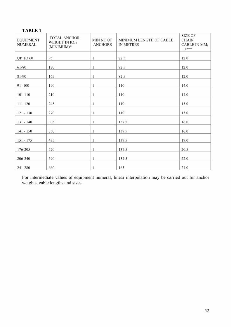
TABLE 1
EQUIPMENT NUMERAL
TOTAL ANCHOR WEIGHT IN KGs (MINIMUM)*
MIN NO OF ANCHORS
MINIMUM LENGTH OF CABLE IN METRES
SIZE OF CHAIN CABLE IN MM; U2**
UP TO 60
95
1
82.5
12.0
61-80
130
1
82.5
12.0
81-90
165
1
82.5
12.0
91 -100
190
1
110
14.0
101-110
210
1
110
14.0
111-120
245
1
110
15.0
121 - 130
270
1
110
15.0
131 - 140
305
1
137.5
16.0
141 - 150
350
1
137.5
16.0
151 - 175
435
1
137.5
19.0
176-205
520
1
137.5
20.5
206-240
590
1
137.5
22.0
241-280
660
1
165
24.0
For intermediate values of equipment numeral, linear interpolation may be carried out for anchor weights, cable lengths and sizes.
52
CHAPTER 5 (FIRE PROTECTION, DETECTION & EXTINCTION) FIRE 85. General 85.1 Every vessel should be so constructed and equipped such that there is no substantial fire risk
to the vessel or to persons on board the vessel. 85.2 Consideration should be given to reducing the use of combustible construction materials
when non-combustible equivalents are readily available. 85.3 The insulating materials used in accommodation spaces, service spaces, control stations and
machinery spaces should be non-combustible. The surface of any insulation fitted on the internal boundaries of machinery spaces should be impervious to oil or oil vapours.
85.4 Within refrigerating compartments, any combustible insulation should be protected by close
fitting linings. 85.5 Exposed surfaces within accommodation spaces, service spaces, control stations, corridor
and stairway enclosures and the concealed surfaces behind bulkheads, suspended ceilings, panelling and linings fitted within those spaces should have low flame spread characteristics.
85.6 Support structure (grounds) to linings and ceilings etc. should be constructed of non-
combustible material. Where it is not practicable to use non-combustible material, the material used should be treated with a suitable fire retarding treatment. N
85.7 Air spaces enclosed behind suspended ceilings, panelling or linings in accommodation
spaces, service spaces and control stations should be divided by close fitting draught stops spaced not more than 7 metres apart.
85.8 Paints, varnishes and other finishes used on exposed interior surfaces should not constitute a
fire hazard and should not, in a fire, produce excessive quantities of smoke, toxic gases or vapour to the satisfaction of the Marine Administration.
In new vessels this should be determined in accordance with the Fire Test Procedures Code. N 85.9 Primary deck coverings within accommodation and service spaces and control stations,
should be of materials which will not readily ignite or give rise to toxic or explosive hazards at elevated temperatures to the satisfaction of the Marine Administration
In new vessels this should be determined in accordance with the Fire Test Procedures Code. N 85.10 Curtains, floor coverings and furnishings should be resistant to flame and ignition to the
satisfaction of the Marine Administration.
53

In new vessels: a) curtains should be resistant to flame propagation in accordance with the Fire Test
Procedures Code; b) all surface floor coverings should have low flame spread; and c) the upholstered parts of furniture should be resistant to ignition and flame propagation, in
accordance with the Fire Test Procedures Code. N 85.11 Pipes conveying oil, combustible liquids or flammable gases should be constructed from
steel or other suitable material. Jointing materials should not be rendered ineffective by heat. 85.12 Plastic piping may be used for services other than those specified in 85.11 provided that
appropriate fire testing, in accordance with the requirements of the Fire Test Procedures Code, has been carried out to the satisfaction of the Marine Administration. The integrity of watertight or fire divisions when penetrated by such pipes should be maintained to the satisfaction of the Marine Administration
85.13 Flammable liquids should always be carried in suitably sealed containers and stowed in a
safe position. 85.14 Fire fighting equipment should always be kept in its proper location, maintained in good
working order, and be available for immediate use. 85.15 The crew should be familiar with the locations of fire fighting equipment, the way it works
and how it should be used. 85.16 The presence of extinguishers and other portable fire fighting equipment should always be
checked before the vessel gets under way. 85.17 Manually operated fire fighting equipment should be readily accessible, simple to use and
should be indicated by signs of durable construction and appropriately positioned. 85.18 Fire detection and alarm systems should be regularly tested and well maintained. 85.19 Fire fighting drills should be carried out at regular intervals (see section 118.) 85.20 The fire protection, detection and extinguishing arrangements on existing vessels will
continue to be accepted providing they are maintained in accordance with previous requirements under the Fishing Vessels (Safety Provisions) Rules 197516, and continue to remain efficient in service. E
16 S.I. 1975 No. 330 as applied to the Isle of Man by GC75/77
54

86. Structural Fire Protection for Vessels with Hulls Constructed of Steel or other Equivalent Material
86.1 In every vessel the superstructure, structural bulkheads, decks and deckhouses should be
constructed of steel or other equivalent material, having due regard to the risk of fire. N 86.2 Subject to sections 86.4 and 86.8, bulkheads and decks bounding main machinery spaces
should be constructed to “A-0” standard. N 86.3 Bulkheads and decks, which separate galleys (or combined galley/mess rooms) from
accommodation spaces, service spaces or control stations should be constructed to “A-30” standard. Alternatively, and subject to section 86.8, where an appropriate fixed fire extinguishing system is fitted such bulkheads and decks may be constructed to “A-0” standard. N
86.4 Where fishrooms are fitted with combustible insulation, bulkheads and decks separating
such spaces from main machinery spaces or galleys (or combined galley/mess rooms) should be constructed to “A-30” standard N
86.5 Bulkheads of corridors serving accommodation spaces, service spaces and control stations,
other than bulkheads required to meet the provisions of sections 86.2 and 86.3 should extend from deck to deck and should be formed of steel, “B-15” class divisions or equivalent. N
86.6 Interior stairways serving accommodation spaces, service spaces or control stations should
be constructed of steel. The enclosures to such stairways should be of steel “B-15” class or equivalent and be fitted with a “B-15” class closing arrangement at one end of each stairway. N
86.7 The number of openings in the bulkheads and decks referred to in sections 86.2 and 86.3
should be the minimum practicable. Such openings should be fitted with closing arrangements that provide fire protection equivalent to the surrounding structure. Any access doors provided in the casing of the main machinery space or galley (or combined galley/mess) should be of “A-30” standard and be self-closing except when such a door is required to be of weathertight construction. N
86.8 Where, due to constraints of design or layout, a life-raft or EPIRB is required to be stowed
over the galley or machinery space, such stowage areas and associated access routes should be insulated to “A-30” standard. N
86.9 Where combustible material is fitted to boundary bulkheads and decks of spaces adjoining
galleys (or combined galley/mess rooms) and main machinery spaces, it should be protected from the effects of heat that may result from a fire in those spaces. N
86.10 Where bulkheads or decks, that are required to be of “A” or “B” class divisions, are
penetrated by pipes, cables, trunks, ducts etc., arrangements should be made to ensure that the fire integrity of the division is not impaired. N
86.11 Where an existing boundary is affected in its entirety during modification or refit to
the vessel, that boundary should, in general, comply with Code requirements. E
55

87. Structural Fire Protection for Vessels with Hulls Constructed of Combustible
Materials 87.1 For vessels primarily constructed of wood and where the superstructure, structural
bulkheads and decks over machinery spaces are constructed of steel or other equivalent material, fire protection arrangements should be fitted as for steel vessels in sections 86.1 to 86.10 above. N
87.2 Subject to section 87.1 in every vessel, the hull of which is constructed of combustible
materials, the decks and bulkheads of machinery spaces and galleys (or a combined galley/mess), should be constructed to meet “F” or “B-15” class standard or equivalent. In addition, such boundaries should as far as practicable prevent the passage of smoke. N
87.3 Decks and bulkheads separating control stations from accommodation spaces, service
spaces or main machinery spaces should be constructed to meet “F” class standard or equivalent. N
87.4 Bulkheads of corridors serving accommodation spaces, service spaces and control stations
should extend from deck to deck and be formed of “F” or “B-15” class divisions or equivalent. N
87.5 Interior stairways serving accommodation spaces, service spaces or control stations should
be constructed of steel. The enclosures to such stairways should be of “F” class divisions or equivalent and be fitted with an appropriate “F” or “B-15” class closing arrangement at one end of each stairway. N
87.6 The number of openings in the bulkheads and decks referred to in sections 87.2 and 87.3
should be the minimum practicable. Such openings should be fitted with closing arrangements that provide fire protection equivalent to the surrounding structure. Any access doors provided in the casing of the main propelling machinery space should be of “F” or “B-15” class and be self-closing except when such a door is required to be of weathertight construction. N
87.7 Where bulkheads or decks, that are required to be of “F” or “B” class divisions, are
penetrated by pipes, cables, trunks, ducts etc., arrangements should be made to ensure that the fire integrity of the division is not impaired. N
87.8 All exposed surfaces of glass reinforced plastic construction within accommodation and
service spaces, control stations, main machinery spaces and other machinery spaces of similar fire risk should have the final lay-up layer of resin having inherent fire retarding properties or be coated with a suitable fire retardant paint or be protected by non-combustible materials. N
87.9 Where an existing boundary is affected in its entirety during modification or refit to
the vessel, that boundary should, in general, comply with Code requirements. E
56

88. Ventilation Systems 88.1 Means should be provided to stop fans and close all main openings to ventilation systems
from outside the spaces served. Means should also be provided for closing funnel ventilation openings. N
88.2 Ventilation openings may be provided in and under the doors in corridor bulkheads but
excluding any doors to stairway enclosures or the machinery space. The net area of any such opening should not exceed 0.05 square metres. N
88.3 Ventilation ducts for main machinery spaces or galleys should not in general pass through
accommodation spaces, service spaces or control stations however they may pass through fish processing or similar spaces having a low fire risk. Similarly ventilation ducts for accommodation spaces, service spaces or control stations should not pass through main machinery spaces or galleys. Where the Certifying Authority permits such arrangements, the ducts should be constructed of steel or a similar material and be arranged to preserve the integrity of the divisions concerned. N
88.4 Ventilation systems serving machinery spaces should be independent of systems serving
other spaces. N 88.5 Ventilation systems to spaces containing appreciable quantities of highly flammable
products should be separate from other ventilation systems. Ventilation should be provided at high and low levels within the space and the external inlets and outlets of such vents should be positioned in safe areas on open deck away from any source of ignition. Vent motors and equipment provided within the system should beintrinsically safe. N
88.6 When trunks or ducts cross a fire rated division then manual fire dampers should be fitted to
prevent the passage of smoke and flame across the division, the dampers should be capable of operation from both sides of the bulkhead or deck, when the cross sectional area of any trunk or duct exceeds 0.02 square metres then the damper should additionally be of the automatic self closing type. N
88.7 Fire dampers may be omitted if the ducting is of substantial construction and equivalent
arrangements have been provided to the satisfaction of the Certifying Authority. N 88.8 Refer also to section 41 (Ventilators). 89. Fire Detection 89.1 All vessels should be fitted with automatic fire detection and alarm systems covering the
machinery spaces, galley and accommodation spaces. Existing vessels not currently fitted with such systems should comply with this requirement by the first intermediate survey conducted under the new Code. E
57

89.2 The fire detection system should be fit for its intended service and be capable of automatically indicating, in the wheelhouse, the presence of fire.
In new vessels the location of the fire should also be indicated. N 89.3 The indicating system for the detection system should comprise of both an audible and
visual alarm within the wheelhouse. 89.4 The system should be supplied from both the main and emergency sources of electric power. 90. Fire Extinction 90.1 Vessels should be provided with:
a) a fixed fire extinguishing system for the main machinery space;
b) a fixed fire extinguishing system for the galley (or combined galley/mess) subject to section 86.3;
c) a power operated fire pump, delivering a minimum of 15 metres3/h at a pressure of not less than 2kg/metres2, supplying a hose or hoses such that a jet of water can reach any part of the vessel accessible to the crew. This pump may be either a general service pump or a bilge pump;
d) at least three portable fire extinguishers situated for use in the accommodation and service spaces with an extinguishing medium suitable to the fire risk involved;
e) at least two portable fire extinguishers suitable for extinguishing oil fires should be provided within the machinery space;
f) a fire blanket for the Galley N
Existing vessels may continue to comply with the requirements of the Fishing Vessels (Safety Provisions) Rules 1975 17 E
91. Fire Extinguishing Equipment 91.1 A fixed fire extinguishing system for the machinery space should be either:
a) a fire smothering gas installation; or
b) a high expansion foam installation; or
c) a stored pressure water spraying installation; or
d) any other fixed fire extinguishing system acceptable to the Marine Administration. N
91.2 The equipment, capacities, controls and alarms for such a system should be arranged and
installed to the satisfaction of the Marine Administration . N
17 S.I. 1975 No. 330 as applied to the Isle of Man by GC75/77
58

91.3 Where air pressure systems and storage bottles in machinery spaces are not vented externally to the machinery space, an appropriate allowance should be made when calculating the required volume of the extinguishing medium required for such spaces.
91.4 Operation of such equipment should be from a position of safety and preferably on the open
deck. N 91.5 Piping systems and fittings for fire services should be of materials that are not rendered
ineffective by heat. Pipes made of steel should be galvanized and suitable drainage provided in deck lines to guard against the possibility of frost damage. A valve or cock should be provided at each delivery position. N
91.6 Portable fire extinguishers should be to BS EN 3 (1996) standard with the following
capacities:
a) water, of at least 9 litres capacity; b) foam, of at least 9 litres capacity; c) CO2, of at least 3 kg capacity; d) Dry powder, of at least 4.5 kg capacity; e) Multi purpose with a capacity at least equivalent to a 9 litre fluid fire extinguisher.
Note: Extinguishers and equipment carrying the Marine Equipment Directive Stamp
(“wheelmark”) are acceptable. N 91.7 Where vessel refit, alteration or modifications are carried out, existing installations
and arrangements may require reconsideration. E 92. Means of Escape and Emergency Exits 92.1 Stairways, ladders and passageways should be arranged to provide ready means of escape
from accommodation spaces and spaces in which the crew is normally employed, to the open deck where the life saving appliances will be available for use.
92.2 At least two means of escape, which may include the normal means of access, should be
provided from accommodation, service or working spaces or groups of such spaces, situated on any one deck level within either watertight or fire resistant boundaries, except that:
a) only one means of escape may be provided where this is considered to be adequate by the
Marine Administration having due regard to the nature and location of the space and the number of persons who might be accommodated or employed there;
b) exceptionally, a suitably sized window may be accepted as a second means of escape for spaces above the weather deck. A grab rail should be fitted above the window and a suitable hammer positioned in a convenient local position. This “designated window” should be marked as an escape and provide access onto a decked area, from which the Life-Saving Appliances may be easily and safely accessed.
92.3 Hatches and doors forming part of an escape route should be readily operable from both
sides by any person or by rescue teams.
59

92.4 All escape routes should be kept clear of obstructions and the clear access and dimensions of such routes should allow for rapid and safe evacuation.
92.5 At least two suitably located means of escape should be provided from the main machinery
space except that where the size of the machinery space renders this impracticable a single means of escape may be accepted. Where ladders are provided for escape, they should be of steel construction.
92.6 Emergency lighting should be arranged to cover all escape routes. 92.7 Emergency routes and exits should be clearly indicated by signs. 92.8 All means of escape should be arranged to the satisfaction of the Marine Administration . 93. Means for Stopping Machinery 93.1 Machinery space ventilation fans, oil fuel transfer pumps, and other similar fuel pumps
should be fitted with remote controls located outside the spaces in which they are situated. These controls should be capable of stopping the machinery or pumps in the event of fire.
93.2 Remote electric stops for ventilation fans serving accommodation spaces should be operable from outside the space.
Miscellaneous Fire Precautions 94. Space heaters
Electric space heaters, where provided, should be constructed and fitted to reduce the fire risk to a minimum and where such heaters are situated on decks or bulkheads the structure of such decks or bulkheads should be protected by non-combustible material. Heaters with exposed elements and open flame fuel heaters should not be provided. N
95 Galley area 95.1 Materials that are in the vicinity of any cooking appliance should be non-combustible,
except that combustible materials may be employed when these are faced with stainless steel or a similar non combustible material. N
95.2 Wherever practicable, electrically powered cooking equipment should be provided in
preference to open flame types. N 95.3 Curtains, towel rails, hooks and similar arrangements should be kept well clear of the
cooking area. N 95.4 Electric stoves and other cooking appliances should be fitted with an isolation switch
outside the galley space. N
60

96. Oil fuel installations (cooking ranges and heating appliances) 96.1 Where cooking ranges or heating appliances within crew spaces are supplied with fuel from
an oil tank, the tank should be situated outside the space containing the cooking range or heating appliance and the supply of oil to the burners should be capable of being controlled from outside that space. Ranges or burners using oil fuel having a flash point of less than 60 degrees centigrade (Closed Cup Test) should not be fitted. Means should be provided to shut off the fuel supply automatically at the cooking range or heating appliance in the event of fire or if the combustion air supply fails. Such means should require manual resetting in order to restore the fuel supply.
96.2 Oil tanks supplying the cooking range or heating appliance should be provided with an air pipe leading to the open air, and in such a position that there will be no danger of fire or explosion resulting from the emergence of oil vapour from the open end of the pipe. The open end should be fitted with a detachable wire gauze diaphragm. (refer also to section 42, Air Pipes)
96.3 Adequate means should be provided for filling every such tank and for preventing
overpressure. 96.4 Closed flame diesel heaters consist of a closed combustion chamber, used to heat air
supplied by an (integral) electric fan. Combustion air inlet and exhaust lines are fitted in isolation to the heating air.
96.5 Closed Flame diesel heaters must comply with the following requirements:
a) The fuel tank is to be fitted outside the space containing the heating appliances;
b) The supply of oil shall be capable of being controlled outside that space (i.e. a remote operated valve shall be fitted);
c) The fuel is to have a flash point of at least 600. The use of petrol is not permitted;
d) Automatic means of fuel shut off must be fitted when the combustion air supply fails. Manual resetting of the device is then necessary to restore the fuel supply;
e) The fuel tank must be fitted with an air pipe, including anti-flash gauze; and
f) Adequate means shall be provided for filling the tank and preventing overpressure.
96.6 In addition to the requirements at section 96.5 the following provisions are strongly
recommended:
a) Fuel supply lines should be made of steel;
b) Combustion air intakes and exhaust should lead to outside the vessel and positioned a sufficient distance apart; and
c) The exhaust should be suitably lagged.
d) In all instances, the manufacturer’s installation instructions must be followed.
61

97. Liquefied Petroleum Gas installations (cooking ranges and heating appliances) 97.1 Installations using liquefied petroleum gas should be properly and safely fitted and fit for
their intended service (guidance may be found in BS EN (ISO) 10239). All valves, pressure regulators and pipes leading from the cylinders should be protected against damage.
97.2 All liquefied petroleum gas heating appliances used in accommodation spaces, including sleeping quarters, should be fitted with a flue to the exterior of the vessel via a clear unblocked exhaust.
97.3 Spaces where appliances consuming liquefied petroleum gas are used should be adequately
ventilated. 97.4 Mechanical ventilation systems fitted to any space in which such gas containers or
appliances are situated should be of such design and construction as will eliminate the hazards due to sparking. The ventilation systems serving spaces containing such gas storage containers or gas consuming appliances should be separate from any other ventilation system.
97.5 Containers holding liquefied petroleum gas should be clearly marked and securely stowed
on deck or in a well ventilated compartment situated on the deck. Where drainage is provided from compartments containing such gas containers, drains should lead directly overboard.
97.6 Spaces containing cooking ranges or heating appliances that use liquefied petroleum gas
should not be fitted with openings leading directly below to accommodation spaces or their passageways, except that where this is not reasonably practicable and such openings are fitted, mechanical exhaust ventilation trunked to within 300 millimetres of the deck adjacent to the appliance, together with adequate supply ventilation, and a gas detector (standard EN50194 ) should be fitted with an alarm in the space below.
97.7 A device should be fitted in the supply pipe from the gas container to the consuming
appliance that will shut off the gas automatically in the event of loss of pressure or low pressure in the supply line. The device should be of a type that requires deliberate manual operation to restore the gas supply. An automatic shut-off device that operates in the event of flame failure should be fitted on all appliances consuming liquefied petroleum gas.
97.8 Open flame gas heating appliances should not be fitted except where used as cooking stoves.
Adequate ventilation should be provided to spaces containing cooking stoves. Pipes supplying gas from the container to the cooking stove should be constructed of suitable material. Arrangements should be provided to ensure automatic cut-off to the supply of gas when there is a loss of pressure or flame failure.
97.9 Heating stoves and other similar appliances should be secured in position and their exhaust,
together with the surrounding structure, provided with adequate fire protection. The exhausts of stoves should be provided with ready means of cleaning. The dampers fitted in exhausts for controlling draught should provide an adequate flow of air when in the closed position. The air supply to these appliances should not be fitted with means of closing.
62

97.10 Every space containing a gas-consuming appliance should be provided with gas detection and audible alarm equipment. The gas detection device should be securely fixed in the lower part of the space in the vicinity of the gas-consuming appliance. The alarm unit and indicating panel should be situated outside the spaces containing the appliance.
97.11 Where gas consuming appliances are used in sleeping quarters or in adjacent spaces, an audible alarm should be fitted in the sleeping quarters in addition to the alarm required by section 97.10
97.12 Atmospheric monitoring devices (i.e. carbon monoxide sensors) should be fitted in all
compartments where liquefied petroleum gas heating appliances are fitted. 97.13 A suitable notice should be displayed prominently in the vessel that details the action to be
taken when a gas alarm activates or a gas leak is suspected. 97.14 As far as is practicable, existing vessels should comply with the requirements of 97
However, a shut down device operated by the alarm stated in section 97.10, may be used in lieu of a flame failure device required in section 97.7. E
98 Portable Plant 98.1 When portable plant is powered by an engine, the unit should be stored on the weather deck.
If such storage is within a deck locker or similar enclosure, then the enclosure should have gas tight boundaries to adjacent spaces. The locker or enclosure should be adequately ventilated and drained.
98.2 Consideration should be given to the exhaust gases produced by portable plant and suitable
ventilation or exhaust trunking provided where necessary to prevent carbon monoxide poisoning.
98.3 Fuel tanks should be arranged to the satisfaction of the Marine Administration. 98.4 Portable containers for the carriage of fuel should be:
a) kept to a minimum;
b) suitable for the carriage of fuel;
c) stowed on the weather deck where they can readily be jettisoned and where any spillage will drain directly overboard; and
d) be clearly marked with their contents.
99 Storage of flammable liquids, toxic liquids, toxic gases and compressed gases 99.1 Cylinders containing flammable, toxic or other dangerous gases, and expended cylinders
should be clearly marked as to their contents and properly stowed and secured on open decks. All valves, pressure regulators and pipes leading from such cylinders should be protected against damage. Such cylinders may be stowed in compartments that meet the requirements set out in section 99.2.
63

99.2 Cylinders and bottles containing flammable, toxic liquids, toxic gases and liquefied gases, other than liquefied petroleum gas should be stored in compartments having direct access from open decks. Such compartments should have boundary bulkheads constructed from non-combustible materials. Pressure adjusting devices and relief valves, if any, should exhaust within the compartment. Where boundary bulkheads of such compartments adjoin other enclosed spaces they should be gas-tight and be provided with ventilation arrangements that are separate from other ventilation systems. Ventilation should be arranged at high and low levels and the inlets and outlets of ventilators should be positioned in safe areas and fitted with spark arresters.
99.3 Electrical wiring and fittings should not be installed within compartments containing highly
flammable liquids or liquefied gases except where necessary for service within the space. Where such electrical fittings are installed they should be suitable for use in a flammable atmosphere.
99.4 Compartments containing compressed gas cylinders should not be used for stowage of other
combustible products or for tools or objects not belonging to the gas distribution system. 99.5 Gas welding and cutting equipment, if carried, should be stowed in a secure manner on the
open deck at a safe distance from any potential source of fire and should have the capability of being readily jettisoned overboard if necessary.
99.6 Any compartment that contains a gas consuming appliance or any compartment into which
flammable gas may leak or accumulate, should be provided with a hydrocarbon gas detector and alarm. N
100. Cleanliness of machinery spaces 100.1 Machinery spaces should be kept clean, free of rubbish and combustible waste. Bilge levels
should be checked regularly and oily waste and sludge should be collected and properly disposed of ashore (see also Chapter 11, section 131.1.).
100.2 Any oil leakage from machinery, fuel or lubricating oil systems should be promptly
identified and rectified.
64

CHAPTER 6 (PROTECTION OF THE CREW) PROTECTION OF PERSONNEL 101 General 101.1 Owners should ensure that their vessels are operated without endangering the safety and
health of the crew. 100.2 The crew should be given training and instructions on health and safety matters on board
fishing vessels, and in particular, on accident prevention. 102. Risk Assessment 102.1 All members of the crew or their representatives should be informed of all measures to be
taken regarding health and safety on board the vessel. Such information should be easily understood by the persons concerned.
102.2 A health and safety risk assessment should be used to satisfy the obligation of providing
information to crew members of the measures taken for their own protection. 102.3 A risk assessment is intended to be a careful examination of what, in the nature of
operations could cause harm, so that decisions can be made as to whether enough precautions have been taken or whether more should be done.
102.4 The assessment should first identify the hazards that are present and then establish whether a
hazard is significant and whether it is already covered by the satisfactory precautions to control the risk, including consideration of the likelihood of the failure of those precautions that are in place.
102.5 It is not a requirement that a risk assessment be written, nevertheless the Marine
Administration strongly recommends that such assessments be written. An example of a suitable standard of written risk assessment is included in the Fishing Vessel Safety Folder developed by Seafish and available from the Marine Administration, which also provides pro-forma guidance on fishing vessel risk assessment, both generally and in relation to particular modes of fishing.
102.6 Where risks to the safety and health of the crew cannot be prevented or sufficiently limited
by collective or technical means of protection, they should be provided with personal protective equipment.
102.7 Personal protective equipment in the form of clothing or over clothing, should be in bright
colours, contrasting with the marine environment and clearly visible. Reference should be made to Part IV of the Merchant Shipping (Safety Officials, General Duties, and Protective Equipment) Regulations 2001 (SD 816/01).
65

103. Precautions against falls including Bulwarks, Guard Rails and Hand Rails 103.1 To ensure the safety of persons against falls, including falling overboard, and when the
proper working of the vessel is not impeded, the perimeters of an exposed deck and the tops of any deckhouse should be provided with a combination of bulwarks, guardrails or taut wires of sufficient strength and at a height of at least 1000 millimetres. These bulwarks, rails or wires should be supported efficiently by stays or stanchions. The openings between the courses of any rails or wires should not exceed 230 millimetres for the lowest course and 380 millimetres for any other course. When application of such measures would impede the proper working of the vessel, equivalent safety measures may be considered.
103.2 On vessels constructed before 1st April 2006 the height of the bulwarks, rails or wires
referred to in sections 103.1 and 103.5 should be at least 915 millimetres. When the application of such measures would impede the proper working of the vessel, equivalent safety measures may be considered. E
103.3 If there is a risk that any member of the crew may fall through openings in the deck, or from
one deck to another, then so far as is reasonably practicable adequate protection should be provided.
103.4 Accesses to installations above the deck for operations or maintenance purposes should be
provided with guard rails or similar protective devices to prevent falls and to ensure the crew’s safety. Where guard rails provide such protection, they should be of appropriate height.
103.5 The minimum height above deck of any fixed bulwarks should be 600 millimetres. All
bulwark heights should be increased as necessary to not less than 1000 millimetres (but see section 103.2) by adequate stanchions or guard wires.
103.6 Access stairways, ladderways and passageways should be provided with hand rails as
necessary and storm rails should be fitted on the outside of all deck houses and casings. 103.7 Adequate guard rails, lifelines, gangways or passages should be provided for the protection
of persons on board the vessel when passing between their quarters, machinery spaces and working spaces.
103.8 On stern trawlers with ramps, the upper part of the ramp should be fitted with a gate or
similar protective guard, of the same height as the bulwarks or adjacent structure, to protect the crew from the risks of falling into the ramp. This gate or other device should be capable of being readily opened and closed, preferably by remote means and should be open only for shooting or hauling the nets. Safety harnesses and lines should be worn when the gate is open. See also section 104.2 below.
103.9 Stairways and ladders should be provided of size and strength adequate for the safe working
of the vessel at sea and in port. Stairways and ladders should be provided with non-slip treads and hand rails.
103.10 Working areas should be kept clear and, so far as is reasonably practicable, be protected
from the sea and provide adequate protection for the crew against falling on the vessel or falling overboard.
66
103.11 Handling areas should be sufficiently spacious, in terms of both height and surface area. 103.12 A gangway or other suitable means, providing an appropriate and safe means of boarding
the vessel should be available. 104. Harnesses 104.1 A vessel should be provided with at least 2 safety harnesses and additional safety harnesses
as necessary for all persons who may be required to work on deck. 104.2 Efficient and permanent means for securing the lifelines of safety harnesses should be
provided on exposed decks. 105. Surface of Working Decks 105.1 The surface of working decks and spaces accessible to the crew should be non-slip or anti-
slip or be provided with devices to prevent falls and kept free of obstacles as far as possible. 105.2 Acceptable surfaces are: chequered plate; unpainted wood; a non-skid pattern moulded into
fibre reinforced plastic (FRP); non-slip deck paint; or an efficient non-slip covering. 106. Winches, Tackles and Hoisting Gear 106.1 Every vessel that is provided with winches, tackles and hoisting gear should have such gear
properly installed having regard to the intended service of the vessel. 106.3 All equipment used in hoisting should be tested and examined at regular intervals. 106.4 All parts of hauling gear, hoisting gear and related equipment should be maintained in good
repair and working order. 106.5 The controls for the hauling gear should be installed in an area sufficiently large to enable
operators to work unhindered. 106.6 The hauling gear should also have appropriate safety devices for emergencies, including
emergency stop facilities. 106.7 The hauling gear operator should have a clear view of the hauling gear and any crew
member working it. 106.8 If the hauling gear is controlled from the wheelhouse, the operator should also have a clear
view of the crew working it, either directly or via any other suitable medium. 106.9 A reliable communications system should be used between the wheelhouse and the working
deck and the crew should be trained in the use of hand signals. 106.10 A sharp look out should always be maintained and the crew warned of the imminent danger
of heavy oncoming seas during fishing operations or when other work is being undertaken on deck.
67

106.11 Contact with bare ropes and warps and with moving parts of the equipment should be
minimized by installing protective devices. 106.12 The following controls should be installed for moving masses (on vessels with trawl doors
or codends): a) devices to immobilize the trawl doors; b) devices to control the swinging motion of the cod end.
106.13 The crew should be trained in the use of fishing gear and hauling equipment. 107. Ventilation of Enclosed Workplaces 107.1 Steps should be taken to ensure there is sufficient fresh air in enclosed workplaces, having
regard to the work methods used and the physical demands that are placed on the crew. 107.2 If a mechanical ventilation system is used, it should be maintained in good condition. 107.3 Effective means of ventilation should be provided to all enclosed spaces that may be entered
by persons on board. 108. Temperature of Working Areas 108.1 The temperature in enclosed working areas should be adequate for the human body during
the hours of working, having regard to the work methods used, the physical demands placed on the crew and the actual or potential weather conditions in the area in which the vessel operates.
108.2 The temperature in living quarters, sanitary facilities and mess rooms should, where these
areas exist, be appropriate to the particular purpose of such areas. 109. Natural and Artificial Lighting of Workplaces. 109.1 Workplaces should as far as possible receive sufficient natural light and be equipped with
artificial lighting suitable for the operations in hand, without placing the crews safety and health in danger or jeopardising the navigation of other vessels.
109.2 Lighting installations in working areas, stairs, ladders and passageways should be placed in
such a way that the type of lighting envisaged poses no risk of accident to the crew and no hindrance to the navigation of the vessel.
109.3 Workplaces in which the crew are especially exposed to risks in the event of failure of
artificial lighting should be provided with emergency lighting of adequate intensity. 109.4 Emergency lighting should be maintained in an efficient operating condition and be tested at
regular intervals. 109.5 The stroboscopic effect of fluorescent lighting should be avoided near machinery. N
68

110. Workplace Soundproofing, Insulation and Cleanliness 110.1 The owner should take appropriate measures to ensure that the vessel and all its fittings and
equipment are cleaned regularly in order to maintain an appropriate standard of hygiene. 110.2 Workstations should be, as far as practicable, adequately soundproofed and insulated,
bearing in mind the type of tasks involved and the physical activity of the crew. 110.3 The surfaces of decks, bulkheads and deckheads in working areas should be such that they
can be cleaned and maintained. 111. Doors 111.1 Means should be provided so that doors can at all times be operated from the inside without
special equipment. 111.2 Doors should be operable from either side when workplaces are in use. 111.3 Doors, and in particular, sliding doors, where such have to be used, should function as safely
as possible for the crew, especially in adverse weather and sea conditions. 112. Securing of Heavy Equipment 112.1 Heavy items of equipment such as spare fishing gear, batteries, cooking appliances etc.,
should be securely fastened in place to prevent movement due to severe motions of the vessel.
112.2 Stowage lockers containing heavy items should have lids or doors with secure fastening.
69

113. MEDICAL STORES A vessel should carry first aid equipment and medical stores in accordance with SD500/96 The Fishing Vessel (Medical Stores) Regulations 1996. For ease of reference the Medical Store Requirements for Category C Fishing Vessels – i.e. those not operating more than 30 nautical miles from land is set out below. MEDICINE / EQUIPMENT REQUIREMENTS QUANTITY Glyceryl Trinitrate spray 400 micrograms metered 200 dose aerosol or transdermal patches 5mgm x 2
1 unit
Codeine phosphate 30 mg tablet. 20 Paracetamol 500mg tablet 50 Hyoscine hydrobromide 0.3mg tablet 60 Antiseptic solution 100ml bottle or 10 antiseptic solution wipes containing 0.015% w/v Chlorhexidine and 0.015% w/v Cetrimide
1
Cetrimide cream, BP 50g tube 1 Laerdal Pocket Mask 1 Bandage - Crepe BP 7.5cm x 4.5m when stretched
2
Elastic adhesive, BP, 2.5 x 4m 1 Triangular of calico, BP, with 2 sides of about 90cm and a base of about 127cm
4
Paraffin gauze dressing BP, size 10cm x 10cm 10 No. 8 Standard BPC Dressings 6 No. 9 Standard BPC Dressings 2 No.15 Standard BPC Dressings 2 No 16 (Eye Pad) 1 Gauze - packet containing one piece of sterile absorbent cotton gauze BP, size 30 x 90cm.
1
Adhesive dressings, assorted, Sterile 20 Zinc Oxide Plaster BP Spool of tape size 2.5cm x 5m 1 Plastic Burn Bags 46 x 31cm 1 Scissors (rustless) of stainless steel throughout (1) Size about 18cm, one blade sharp- pointed and the other round-ended; conforming to British Standards Institution Standard BS 3646 published on 19.7.63. (2) Size 12.5cms both blades sharp pointed
1 1
Scissors disposable sterile 1 Safety pins rustless medium 20 Disposable polythene gloves large 5
70
CHAPTER 7 (LIFE-SAVING APPLIANCES) LIFE SAVING APPLIANCES General 114.1 Life saving appliances that are required to be of approved type should be approved to
SOLAS 1974 convention requirements, as amended, by a signatory Administration to that convention, or by a recognised classification society
114.2 Life saving appliances that are not required by this chapter to be of approved type should be
to the satisfaction of the Marine Administration. 114.3 Adequate instructions for use should be provided with each life saving appliance and also
adjacent to its stowage position when appropriate. 114.4 Life saving appliances intended for use in the sea should be fitted with retro reflective
markings to the satisfaction of the Marine Administration 115. Vessel Requirements 115.1 The following life saving appliances should be provided:
a) at least two liferafts of approved type, each able to accommodate all persons onboard. One of the liferafts should be capable of being launched from either side of the vessel. Vessels which operate in sea area A1*, that are not engaged in trawling with beams may, as an alternative to complying with this requirement, be fitted with just one liferaft, provided it is of sufficient capacity to accommodate all persons on board and capable of being launched from either side of the vessel;
*sea area A1 meaning an area within the Radiotelephone coverage of at least one VHF coast station in which continuous DSC alerting is available, and specified as such an area in Volume 5 of the Admiralty list of Radio Signals.
b) a lifejacket of approved type for every person on board plus an additional two lifejackets; c) at least two lifebuoys, one of which should be provided with a self igniting light and self
activating smoke signal and the other provided with a buoyant line of at least 18 metres in length, all of approved type;
d) means of recovering a person from the water; e) a line throwing appliance of approved type, with minimum two shot capability; f) 6 rocket parachute flares, of approved type; and g) 2 buoyant smoke signals, of approved type; and h) 4 red hand flares, of approved type
After the 1st April 2006 existing arrangements for pyrotechnics which comply with the provisions of the 1975 rules will continue to be acceptable until their expiry date. Any replacement of pyrotechnics after the 1st April 2006 shall be in accordance with the requirements of paragraph f.
i) one hand held VHF radio, of an approved type; j) one float free satellite EPIRB, of an approved type.
71

116. Availability, Stowage and Maintenance of Survival Craft and Life Saving Appliances 116.1 All items of life-saving and survival equipment required by this Code should:
a) be serviced annually or in accordance with the manufacturers instructions;
b) be mounted or stowed correctly in their assigned locations;
c) be maintained in good working order and be ready for use;
d) be checked before the vessel leaves port and whilst at sea; and
e) be inspected at regular intervals.
116.2. Liferafts should:
a) be readily available for safe and rapid use in an emergency, taking into account any adjacent fire risk;
b) be capable of being launched under unfavourable conditions of trim and with the vessel heeled 15degrees either way;
c) be stowed in such a manner as to permit them to float free from their stowage, inflate and break free from the vessel in the event of its sinking;
d) be stowed clear of any overhanging projections, gear or rigging that could impede the liferafts float free operation;
e) be provided with SOLAS B pack equipment or equivalent.
Note: Lashings if used, should be fitted with an automatic (hydrostatic) release system of an
approved type. The liferaft and any hydrostatic securing and release system should be installed strictly in accordance with the manufacturer’s instructions. Liferafts and serviceable hydrostatic release units should be serviced annually by an authorised agency. Non-serviceable hydrostatic release units should be replaced by their expiry date.
116.3 Every EPIRB should:
a) be fitted with a float free arrangement, whose operation will cause it to activate;
b) be stowed in such a position that it is protected from possible damage and is easily removable from its mounting for placing in any survival craft;
c) have the float-free arrangement routinely replaced or serviced in accordance with the manufacturers instructions;
d) have the power source replaced whenever necessary and at least before its expiry date;
e) be registered,
f) comply with IMO Resolution A810 (19)/ETS 300 062 (second edition) when renewed.
72
116.4 Lifejackets should:
a) be stowed either in a deckhouse or other dry and readily accessible position;
b) have stowage positions clearly and permanently marked;
c) be provided with a light complying with SOLAS 1974 as amended;
d) be serviced in accordance with the manufacturer’s instructions.
116.5 Lifebuoys should:
a) be stowed near the bridge or on an exposed working deck;
b) not be permanently secured;
c) be marked with the vessel name and port of registry or fishing vessel number.
116.6 Line throwing appliances and pyrotechnic signals should:
a) be stowed on or near the bridge in a dry and readily accessible location, clearly marked;
b) be packed in suitable containers.
117. Embarkation into liferafts 117.1 Arrangements should be made for warning the crew when the vessel is about to be
abandoned. 117.2 For vessels with embarkation areas, positioned more than 3 metres above the waterline,
ladders or other suitable means should be provided to allow for safe embarkation into the liferafts.
117.3 Liferaft launching and embarkation positions (including the water into which the liferaft is
launched) should be illuminated by means of both main and emergency sources of power.
73
CHAPTER 8 (EMERGENCY PROCEDURES) EMERGENCY PROCEDURES 118. Inspections
Inspections of the life-saving equipment and fire appliances should be made at intervals of not more than one month.
119. Drills 119.1 The skipper should ensure that the crew are trained in the use of all lifesaving and fire
appliances and equipment with which the vessel is provided and should ensure that all members of the crew know where the equipment is stowed. Such training should be carried out in drills, held in port or at sea, at intervals of not more than one month.
119.2 The drills referred to in section 119.1 should ensure that the crew thoroughly understand and
are exercised in the duties which they have to perform with respect to the handling and operation of all life-saving, fire fighting and survival equipment. Flooding drills should also be incorporated.
119.3 If a vessel carries 5 or more crew, a muster list should be provided with clear instructions for
each member of the crew, which should be followed in case of emergency. 119.4 The times, dates and particulars of inspections and drills should be recorded in a diary or
similar and available for future inspection.
74

CHAPTER 9 (COMMUNICATIONS & NAVIGATION) 120. RADIO EQUIPMENT 120.1 Every vessel should be capable of maintaining an effective radio watch, including
communication, transmission and reception of distress signals in the Global Maritime Distress Signal System (GMDSS) appropriate to the area in which it operates.
120.2 The vessel’s crew should be familiar in the operation of the hand held VHF and the EPIRB
and be trained in the setting up and operation of the portable radio equipment. 120.3 Reference should be made to SD72/06 The Fishing Vessel (Radio) Regulations 2006. 121. NAVIGATION LIGHTS, SHAPES AND SOUND SIGNALS 121.1 Vessels should be equipped to enable display of the navigation lights, shapes and sound
signals appropriate to all foreseeable modes of operation, in daylight, darkness and in restricted visibility, in accordance with international requirements.
121.2 Reference should be made to the Merchant Shipping (Distress Signals and Prevention of
Collisions) Regulations 1996 (SD 389/96). 122. VISIBILITY FROM THE WHEELHOUSE 122.1 Every vessel should be so constructed that the person steering has a clear view to the sea
surface, 90 metres ahead, when at the principal steering position from within the wheelhouse. N
122.2 When the ship’s bridge is totally enclosed, the officer in charge of the navigational watch
should be able to hear sound signals and determine their direction. N
NAVIGATIONAL EQUIPMENT 123. Compass 123.1 Vessels should be fitted with a properly adjusted standard magnetic compass, or other means
independent of any power supply to determine the vessel’s heading and display (with electric light) the reading at the main steering position. Vessels fitted with a standard magnetic compass should have a valid deviation card. The owner and skipper are responsible for compass maintenance, and should monitor compass performance frequently. Adjustments and repairs should only be carried out by a certified compass adjuster.
123.2. A pelorus or compass bearing device, or other means, independent of any power supply, to
take bearings over an arc of the horizon of 360o , shall be carried on board.
75

124. Other Navigational Equipment 124.1 Vessels should be provided with efficient means acceptable to the Marine Administration
for:
a) locating position;
b) measuring speed and distance; and
c) measuring the depth of water.
124.2 Electronic aids to navigation should be tested frequently and well maintained. 125. Nautical Publications 125.1 Nautical charts and nautical publications to plan and display the ships route for the intended
voyage and to plot and monitor positions throughout the voyage should be carried. Subject to paragraph 125.4 an electronic chart display and information system (ECDIS) may be accepted as meeting the chart carriage requirements of this subparagraph.
125.2 The charts to be carried should be those
a) that are of such a scale and which contain sufficient detail as clearly to show: i. all navigation marks that may be used by a vessel when navigating the waters that are
comprised in the chart; ii. all known hazards affecting those waters; and
iii. any information concerning traffic separation schemes, two-way routes, recommended tracks, inshore traffic zones and deep water routes applicable to those waters, as well as areas that are to be avoided;
b) that are either published by the Hydrographer of the Navy or any authority in any country
other than the United Kingdom duly exercising functions similar to those of the Hydrographer, and are of a similar scale and contain equivalent detail; and
c) which, in all cases, are of the latest available edition and have been adequately corrected. 125.3 An equivalent electronic chart display and information system (ECDIS) may be accepted as
meeting the chart obligations of section 125.2. 125.4 Reference should be made to the Merchant Shipping (Safety of Navigation – SOLAS
Chapter V) Regulations 2004 (SD 269/04) which requires back-up arrangements to meet the functional requirements of paragraph 125.1 if this function is partly or fully fulfilled by electronic means. An appropriate folio of paper nautical charts may be used as a back-up arrangement for ECDIS. The back-up should display in graphical (chart) form the relevant information of the hydrographic and geographic environment which are necessary to get back to a safe haven.
76

126. Signalling Lamp/Light for Use During Search and Recovery 126.1 Vessels should be provided with either:
a) a portable waterproof electric torch suitable for morse signalling and a searchlight; or
b) an efficient portable daylight signalling lamp with searchlight capability.
126.2 Portable equipment should be provided with batteries of sufficient capacity for not less than
two hours continuous operation and spare bulbs. 127. Miscellaneous Equipment Vessels should be provided with a radar reflector.
77

CHAPTER 10 (CREW ACCOMMODATION) ACCOMMODATION 128. Vessel Requirements 128.1 The crew’s living quarters, where they exist, should be such as to minimize noise, vibration,
the effects of motion and acceleration and unpleasant odours from other parts of the vessel. 128.2 On vessels with crew accommodation, toilets, wash basins and if possible a shower should
be installed and the respective areas should be properly ventilated. 128.3 Adequate stowage facilities for clothing and personal effects should be provided for each
person on board. 128.4 The galley and mess room, where these exist, should be of adequate size, well lit and
ventilated and easy to clean. 128.5 A refrigerator or other low temperature food storage should be provided. 128.6 As far as is practicable, technical measures should be taken to reduce noise levels in
working and accommodation spaces. 128.7 An electric lighting system should be installed that is capable of supplying adequate light to
all enclosed accommodation and working spaces. 128.8 An adequate supply of fresh drinking water should be provided. 129. Additional Requirements 129.1 The location, structure, soundproofing, means of insulation and layout of the crew
accommodation and means of access should be such as to provide adequate protection against weather and sea, vibration, noise and unpleasant odours from other parts of the vessel likely to disturb the crew during their period of rest.
129.2 Where the design, dimensions or purpose of the vessel allow, the crew accommodation
should be located so as to minimise the effects of motion and acceleration. 129.3 Appropriate measures should be taken as far as possible to protect non-smokers from
discomfort caused by tobacco smoke. 129.4 Appropriate lighting should be provided within the living quarters such that:
a) adequate general lighting is provided;
b) reduced lighting is provided in way of crew sleeping spaces;
c) local lighting is provided for each berth.
129.5 On vessels with crew accommodation, shower facilities with hot and cold running water
should be provided.
78

129.6 Hot water supply systems (if fitted) should be suitably designed, installed and fit for
purpose. 129.7 Crew accommodation spaces should be properly ventilated to ensure a constant supply of
fresh air and to prevent condensation. 129.3 Recommendations for Existing Vessels of less than 18m in length LBP that are at sea for
more than 24 hours: When a vessel is intended to be at sea for more than 24 hours an adequate standard of
accommodation should be provided on board. In considering such accommodation, the primary concern should be directed towards providing facilities that contribute to the health and welfare aspects of those on board i.e. the sleeping accommodation, the ventilation, the sanitary facilities, the lighting and the fresh water and galley services. Whenever possible, consideration should be given to providing the facilities that are detailed in section 128. E
130 SIGNS
All vessels should display a “SOLAS No.2 table” on the bridge and the following signs should be displayed where appropriate;
a) “Emergency escape” (Luminescent, Green/White) to indicate escape routes;
b) “Keep closed at sea” (Blue/White) on both sides of those doors which require to be closed at sea to satisfy stability requirements;
c) “First Aid” (Green/White) at the first aid locker;
d) “Fire-fighting equipment”, (Red/White) for fire extinguishers, CO2 release stations, fire hydrants and hose stowage and push button alarms;
e) “Oil discharge prohibited at sea” (Blue/White) at overboard discharges that are capable of discharging oily bilge water;
f) Other signs, when identified through risk assessment.
79

CHAPTER 11 (CLEAN SEAS) 131. CLEAN SEAS 131.1 All vessels should comply with international, national, regional and local requirements for
the prevention of marine pollution that are applicable to the area in which the vessel is operating. Responsibility for the vessel to be properly equipped and maintained and to ensure that the skipper receives up-to-date and adequate information, rests mainly with the owner.
131.2 Oily residues and garbage or refuse should be landed ashore at proper disposal facilities and
not discharged or dumped into the sea. 131.3 Owners should be aware of the following in relation to the prevention of pollution of the
sea: Sewage - When the direct overboard discharge of sewage is prohibited by
administrations/authorities in an area of operation, the provision of “holding tanks” of sufficient capacity to store waste for discharge to shore facilities may be needed for a vessel to comply.
Garbage - The disposal of garbage into the sea is regulated by Merchant Shipping
(Prevention of Pollution by Garbage) Regulations 1999 (SD 79/99). Arrangements for the retention of garbage on board and for discharge to shore reception facilities should be provided. Arrangements should be varied as necessary to comply with special requirements that may be applied by Administrations/authorities in the area in which a vessel operates.
Oil - The prevention of oil pollution requirements are contained within the Merchant
Shipping (Prevention of Oil Pollution) Regulations 1986 (GC 214/86) and any subsequent amendments of these regulations. Section 14 (4) stipulates the requirements for vessels less than 400 GT (retention/oil filtering equipment).
Air Pollution - Vessels under 400 GRT are not required to have an International Air
Pollution Prevention Certificate however they are required to have an Engine International Air Pollution Prevention Certificate (EIAPPC) for any diesel engine fitted on board if any of the following apply:
• A Diesel Engine with a power output greater than 130 kW installed on a ship whose keel
was laid on or after 1st January 2000. This means that if an engine is replaced for a new one then it must be supplied with an EIAPPC; or
• A Diesel Engine with a power output greater than 130 kW installed on any ship regardless of age which undergoes a major conversion, on or after the 1st January 2000.
A major conversion is not a ‘like-for-like’ exchange of components. A major conversion is
defined in the NOx technical code and generally applies when any of the components affecting the combustion process such as: fuel pumps; fuel injectors; exhaust; and air inlet components, are modified from the original design or where an existing engine’s maximum continuous power output rating is increased by more than 10%.
80

As the Isle of Man Marine Administration does not issue EIAPPC's, you are advised that these certificates will have to be obtained directly from the manufacturers for new or replacement engines and in the case of a major conversion the engines will have to be re-tested and a certificate obtained from the company carrying out the modifications.
81

Annex 1 Government of the Isle of Man Form FV1 Version**** 200* In duplicate Ref. No.
IS
FV No
T
his is 1. th
C(L
2. thap
3. th4. th
reapac
5. than
6. th This certific****** of therecorded da Issued at The underscertificate Survey Com Signed Name Department o
LE OF MAN FISHING VESSEL CERTIFICATE Issued under the provisions of the Merchant Shipping Act 1985
Name of Vessel Port of Registry
Gross Reg. Length . Tonnage Length Overall Reg. Power Date Keel Laid
to certify: e vessel has been surveyed in accordance with section ***** of the provisions of the ode of Practice for the Construction and Use of 15 metres (LOA) to less than 24 metres ) Fishing Vessels; e vessel has been found to comply with the requirements of the Code that are plicable to the vessel; e life saving appliances are sufficient for a total of persons; e vessel is fitted with the lights, shapes and sound signals to comply with the quirements of the International Regulations for the Prevention of Collisions at Sea as plicable and is fitted with navigational equipment and carries nautical publications in cordance with Code; e fishing vessel complies with the Radio Regulations that are applicable to the vessel d is equipped for operation in sea area(s) only; and e fishing vessel has been assigned the operating limits (if applicable).
ate is valid until subject to a satisfactory inspection in accordance with section Code being completed not less than 27 months and not more than 33 months from the te of the renewal survey.
on the igned declares that he is duly authorised by the said Government to issue this
pletion date
Official Stamp f Trade and Industry
82
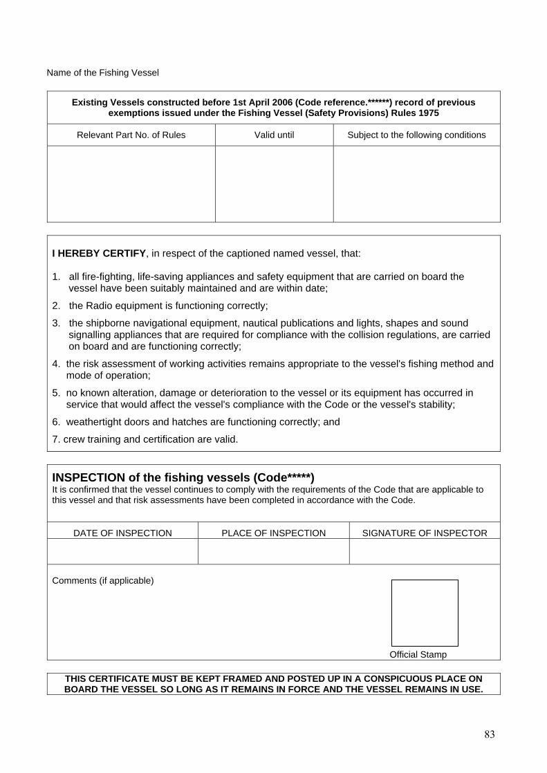
Name of the Fishing Vessel
Existing Vessels constructed before 1st April 2006 (Code reference.******) record of previous exemptions issued under the Fishing Vessel (Safety Provisions) Rules 1975
Relevant Part No. of Rules Valid until Subject to the following conditions
I HEREBY CERTIFY, in respect of the captioned named vessel, that: 1. all fire-fighting, life-saving appliances and safety equipment that are carried on board the
vessel have been suitably maintained and are within date; 2
. the Radio equipment is functioning correctly;
3. the shipborne navigational equipment, nautical publications and lights, shapes and sound signalling appliances that are required for compliance with the collision regulations, are carried on board and are functioning correctly;
4. the risk assessment of working activities remains appropriate to the vessel's fishing method and mode of operation;
5. no known alteration, damage or deterioration to the vessel or its equipment has occurred in service that would affect the vessel's compliance with the Code or the vessel's stability;
6
. weathertight doors and hatches are functioning correctly; and
7
. crew training and certification are valid.
INSPECTION of the fishing vessels (Code*****) It is confirmed that the vessel continues to comply with the requirements of the Code that are applicable to this vessel and that risk assessments have been completed in accordance with the Code.
DATE OF INSPECTION PLACE OF INSPECTION SIGNATURE OF INSPECTOR
Comments (if applicable)
Official Stamp
THIS CERTIFICATE MUST BE KEPT FRAMED AND POSTED UP IN A CONSPICUOUS PLACE ON BOARD THE VESSEL SO LONG AS IT REMAINS IN FORCE AND THE VESSEL REMAINS IN USE.
83
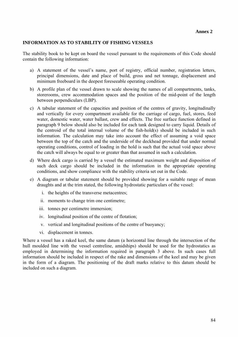
Annex 2
INFORMATION AS TO STABILITY OF FISHING VESSELS The stability book to be kept on board the vessel pursuant to the requirements of this Code should contain the following information:
a) A statement of the vessel’s name, port of registry, official number, registration letters, principal dimensions, date and place of build, gross and net tonnage, displacement and minimum freeboard in the deepest foreseeable operating condition.
b) A profile plan of the vessel drawn to scale showing the names of all compartments, tanks, storerooms, crew accommodation spaces and the position of the mid-point of the length between perpendiculars (LBP).
c) A tabular statement of the capacities and position of the centres of gravity, longitudinally and vertically for every compartment available for the carriage of cargo, fuel, stores, feed water, domestic water, water ballast, crew and effects. The free surface function defined in paragraph 9 below should also be included for each tank designed to carry liquid. Details of the centroid of the total internal volume of the fish-hold(s) should be included in such information. The calculation may take into account the effect of assuming a void space between the top of the catch and the underside of the deckhead provided that under normal operating conditions, control of loading in the hold is such that the actual void space above the catch will always be equal to or greater than that assumed in such a calculation.
d) Where deck cargo is carried by a vessel the estimated maximum weight and disposition of such deck cargo should be included in the information in the appropriate operating conditions, and show compliance with the stability criteria set out in the Code.
e) A diagram or tabular statement should be provided showing for a suitable range of mean draughts and at the trim stated, the following hydrostatic particulars of the vessel:
i. the heights of the transverse metacentres;
ii. moments to change trim one centimetre;
iii. tonnes per centimetre immersion;
iv. longitudinal position of the centre of flotation;
v. vertical and longitudinal positions of the centre of buoyancy;
vi. displacement in tonnes.
Where a vessel has a raked keel, the same datum (a horizontal line through the intersection of the hull moulded line with the vessel centreline, amidships) should be used for the hydrostatics as employed in determining the information required in paragraph 3 above. In such cases full information should be included in respect of the rake and dimensions of the keel and may be given in the form of a diagram. The positioning of the draft marks relative to this datum should be included on such a diagram.
84

f) A diagram or table should be provided showing cross curves of stability indicating the assumed position of the axis from which the righting levers are measured and the trim which has been assumed. Where a vessel has a raked keel a horizontal datum through the intersection of the hull moulded line with the vessel centreline, amidships, should be used. On existing vessels, any datum other than a horizontal line through the intersection of the hull moulded line with the vessel centreline, amidships, should be clearly defined. E
g) The information provided under paragraphs 5 and 6 above should be at such a nominal trim that represents accurately the vessel in all normal operating trims. Where calculations show that there are significant numerical variations in these operating trims the information provided under paragraphs 5 and 6 above should be repeated over such a range of trims to allow an accurate interpolation of such information at any normal operating trim.
h) Superstructure deckhouses, companionways located on the freeboard deck, including hatchway structures may be taken into account in deriving such cross-curves of stability provided that their location, integrity and means of closure will effectively contribute to the buoyancy.
An example should be included in such information to show the corrections applied to the transverse metacentric height and righting levers (GZ) for the effects of the free surfaces of liquids in tanks and should be calculated and taken into account as follows:
the metacentric height in metres should be reduced by an amount equal to the total of the free surface functions for each tank divided by the vessel’s displacement in tonnes. For each tank the free surface function is given by:
1.025 x pi where p = specific gravity of the liquid;
i = transverse moment of inertia of the surface
(i = LB3 where L=length and B=breadth of the free surface in metres)
12
i.e. correction = Sum of pi
Displacement
the righting lever (GZ) curves should be corrected by either:
1) adding the free surface correction calculated under (i) above to the value in metres of the calculated height of centre of gravity of the vessel above datum; or
2) making direct calculations of the heeling moment due to the liquid surface being inclined at the selected angle of heel where such calculations take proper account of the position of liquid surface in relation to the geometric configuration of the tank. The correction to the righting lever (GZ) at any selected angle of heel should then be the summation of the individual heeling moments of the tanks considered, divided by the vessels displacement.
85

i) A stability statement and diagram should be provided for the usual condition of the vessel:
a. in the lightship condition: the vessel should be assumed to be empty except for liquids in machinery and in piping systems including header tanks. The weight and position of the centre of gravity of any permanent ballast or fishing gear should be indicated;
b. in each of the following circumstances so far as they may be applicable to the vessel in its foreseeable operating conditions:
i. on departure from port: the vessel should be assumed to be loaded with the necessary equipment, materials and supplies including ice, fuel, stores and water;
ii. on arrival at fishing grounds: as sub-paragraph (a) above but account taken of the consumption of fuel and stores;
iii. on arrival at fishing grounds: as sub-paragraph (b) above but the appropriate icing-up allowance as set out in paragraph 14 below should be taken into account;
iv. on departure from fishing grounds: the vessel should be assumed to be loaded with its maximum catch but account taken of the consumption of fuel and stores;
v. on departure from fishing grounds: as sub-paragraph (d) above but the appropriate icing-up allowance as set out in paragraph 14 below should be taken into account;
vi. on departure from fishing grounds: the vessel should be assumed to be loaded with 20% of its maximum catch but account taken of the consumption of fuel and stores;
vii. on departure from fishing grounds: as sub-paragraph (f) above but the appropriate icing-up allowance as set out in paragraph 14 below should be taken into account;
viii. on arrival at port with maximum catch: account should be taken of the consumption of fuel and stores;
ix. on arrival at port with 20% maximum catch: account should be taken of the consumption of fuel and stores;
x. if any part of the catch normally remains on deck, further statements and diagrams appertaining to that condition in all the appropriate circumstances set out in subparagraphs (d) to (i) inclusive should be provided;
The total free surface correction for the effect of liquid in tanks should be applied to each loading condition set out in the foregoing provisions of this paragraph. The free surface correction should take into account the amounts of fuel, lubricating oil, feed and fresh water in the vessel in each such loading condition.
86
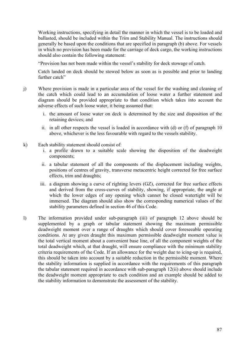
Working instructions, specifying in detail the manner in which the vessel is to be loaded and ballasted, should be included within the Trim and Stability Manual. The instructions should generally be based upon the conditions that are specified in paragraph (b) above. For vessels in which no provision has been made for the carriage of deck cargo, the working instructions should also contain the following statement:
“Provision has not been made within the vessel’s stability for deck stowage of catch.
Catch landed on deck should be stowed below as soon as is possible and prior to landing further catch”
j) Where provision is made in a particular area of the vessel for the washing and cleaning of the catch which could lead to an accumulation of loose water a further statement and diagram should be provided appropriate to that condition which takes into account the adverse effects of such loose water, it being assumed that:
i. the amount of loose water on deck is determined by the size and disposition of the retaining devices; and
ii. in all other respects the vessel is loaded in accordance with (d) or (f) of paragraph 10 above, whichever is the less favourable with regard to the vessels stability.
k) Each stability statement should consist of:
i. a profile drawn to a suitable scale showing the disposition of the deadweight components;
ii. a tabular statement of all the components of the displacement including weights, positions of centres of gravity, transverse metacentric height corrected for free surface effects, trim and draughts;
iii. a diagram showing a curve of righting levers (GZ), corrected for free surface effects and derived from the cross-curves of stability, showing, if appropriate, the angle at which the lower edges of any opening which cannot be closed watertight will be immersed. The diagram should also show the corresponding numerical values of the stability parameters defined in section 46 of this Code.
l) The information provided under sub-paragraph (iii) of paragraph 12 above should be
supplemented by a graph or tabular statement showing the maximum permissible deadweight moment over a range of draughts which should cover foreseeable operating conditions. At any given draught this maximum permissible deadweight moment value is the total vertical moment about a convenient base line, of all the component weights of the total deadweight which, at that draught, will ensure compliance with the minimum stability criteria requirements of the Code. If an allowance for the weight due to icing-up is required, this should be taken into account by a suitable reduction in the permissible moment. Where the stability information is supplied in accordance with the requirements of this paragraph the tabular statement required in accordance with sub-paragraph 12(ii) above should include the deadweight moment appropriate to each condition and an example should be added to the stability information to demonstrate the assessment of the stability.
87

m) The icing-up allowance which represents the added weight due to ice accretion on the exposed surfaces of the hull, superstructure, deck, deckhouses and companionways should be calculated as follows:
i. full icing allowance: all exposed horizontal surfaces (decks, house tops, etc.) should be assumed to carry an ice weight of 30 kilogrammes per square metre. The projected lateral area of the vessel above the waterline (a silhouette) should be assumed to carry an ice weight of 15 kilogrammes per square metre. The height of the centre of gravity should be calculated according to the heights of the respective areas and in the case of the projected lateral area the effect of sundry booms, rails, wires, etc., which will not have been included in the area calculated should be taken into account by increasing by 5% the weight due to the lateral area and the moment of this weight by 10%. This allowance should apply in winter (1st November to 30th April inclusive in the northern hemisphere) to vessels which operate in the following areas:
a. the area north of latitude 66º30’N. between longitude 10ºW. and the Norwegian Coast;
b. the area north of latitude 63ºN. between longitude 28ºW. and 10ºW.;
c. the area north of latitude 45ºN. between the North American continent and longitude 28ºW.;
d. all sea areas north of the European, Asian and North American continents east and west of the areas defined in (a), (b) and (c) above;
e. Bering and Okhotsk seas and Tatar Strait;
f. South of latitude 60ºS.
ii. Half of the full icing allowance:
this should be taken as one half of that calculated under sub-paragraph (i) of this paragraph and should apply in winter to vessels which operate in all areas north of latitude 61ºN. between longitude 28ºW. and the Norwegian Coast and south of the areas defined as the lower limit for the full icing allowance between longitude 28ºW. and the Norwegian Coast.
88

n) Information should be provided in respect of the assumptions made in calculating the condition of the vessel in each of the circumstances set out in paragraph 10 above for the following:
i. duration of the voyage in terms of days spent in reaching the fishing grounds, on the grounds and returning to port;
ii. the weight and disposition of the ice in the hold at departure from port including the heights of stowage;
iii. consumption rates during the voyage for fuel, water, stores and other consumables;
iv. ratio by weight of the ice packed with the catch in the fish hold;
v. melting rates for each part of the voyage of the ice packed with the catch and the ice remaining unused in the hold.
o) A copy of a report of an inclining test of the vessel and the derivation there from of the lightship particulars should be provided.
p) A statement should be given by or on behalf of the owner of the vessel that the statements and diagrams supplied with respect to the operating conditions set out in paragraph 10 above are based on the worst foreseeable service conditions in respect of the weights and disposition of fish carried in the hold or on deck, ice in the hold, fuel, water and other consumables.
89