the jea large-scale cfb combustion demonstration project
TRANSCRIPT

TOPICAL REPORT NUMBER 22 March 2003
The JEA Large-Scale CFB Combustion Demonstration Project

topical report number 22 March 2003
A report on a project conducted jointly under a Cooperative Agreement between: The U.S. Department of Energy and JEA
The JEA Large-Scale CFB Combustion Demonstration Project

Cover Picture:
Three views of JEA Northside Station,Jacksonville, Florida

The JEA Large-Scale CFB Combustion Demonstration Project
Executive Summary ..........................................................................1
Background .......................................................................................2
Project Description............................................................................3
Process Description...........................................................................5
Environmental Considerations..........................................................7
Project Cost.......................................................................................9
Project History ................................................................................11
Project Objectives ...........................................................................16
Project Scope ..................................................................................17
Fluidized Bed Combustion Systems ...............................................19
Demonstration Test Program ..........................................................23
Operating Results............................................................................23
Awards ............................................................................................24
Commercial Applications................................................................24
Conclusions.....................................................................................24
Bibliography ...................................................................................25
List of Acronyms and Abbreviations ..............................................26
Contacts for CCT Projects and U.S. DOE CCT Program...............28


1
Executive Summary
The Clean Coal Technology (CCT) Dem-onstration Program is a government and industry co-funded ef fort to demonstrate a new generation of innovative coal utilization processes in a series of facilities built across the country. These projects are carried out on a commercial scale to prove technical feasi-bility and provide the information required for future applica tions.
The goal of the CCT Program is to furnish the marketplace with a number of advanced, more effi cient coal-based technologies that meet strict envir onmental standards. Use of these tech nologies is intended to minimize the econ omic and en viron mental barriers that limit the full utilization of coal.
To achieve this goal, beginning in 1985, a multi-phased effort consisting of fi ve separate solic itations was admini stered by the U.S. De partment of Energy’s (DOE) National Energy Technol ogy Laboratory (NETL). Pro jects se lected through these solicita tions have demonstrated technology options with the poten tial to meet the needs of en ergy markets while satis fying relevant envir onment al requirements.
Part of this Program is the demonstra-tion of advanced electric power generation technologies, including circulating fl uidized bed combustion (CFB). This report discusses the JEA Large-Scale CFB Combustion Dem-onstration Project which is testing the CFB concept using inexpensive feedstocks such as high sulfur coal and coal fuel blends.
The project is being conducted at the Northside Generating Station of JEA (for-merly Jacksonville Electric Authority) in Jacksonville, Florida, and JEA is the project Participant. Foster Wheeler Energy Corpora-tion, the technology supplier, is an additional team member.
To date, the JEA Project has operated CFBs to generate electricity at a scale larger than previously demonstrated. The boilers at the Northside Station are the largest CFBs in the world. Power production on coal feed meets the target goal of 297.5 MWe gross (265 MWe net). Emissions of atmospheric pollutants are below the stringent limits set for this project. A two-year demonstration test program is planned to evaluate the op-erational and environmental performance of the CFB system.
JEA plant with CFB boilers in center and fuel storage domes in background

2 3
The JEA Large-Scale CFB Combustion Demonstration Project
BackgroundThe Clean Coal Technology (CCT) Dem-
onstration Program, sponsored by the U.S. De-partment of Energy (DOE) and administered by the National Energy Technology Laboratory (NETL), has been conducted since 1985 to develop innovative, environmentally friendly coal utilization processes for the world energy marketplace.
The CCT Program, which is co-funded by industry and government, involves a series of demonstration projects that provide data for design, construction, operation, and technical/economic evaluation of full-scale applications. The goal of the CCT Program is to enhance the utilization of coal as a major energy source.
Fluidized Bed CombustionAmong the technologies being demon-
strated in the CCT Program is fluidized bed combustion (FBC). FBC is an advanced electric power generation process that minimizes the formation of gaseous pollutants by controlling coal combustion parameters and by injecting a sorbent (such as crushed limestone) into the combustion chamber along with the fuel. In the
JEA project described in this report, the fuel is coal or a blend of coal and petroleum coke. Crushed fuel mixed with the sorbent is fluid-ized on jets of air in the combustion chamber. Sulfur released from the fuel as sulfur dioxide (SO2) is captured by the sorbent in the bed to form a solid compound that is removed with the ash. The resultant by-product is a dry, benign solid that can be disposed of eas-ily or used in agricultural and construction applications. More than 90% of the sulfur in the fuel is captured in this process.
An additional environmental benefit of FBC power plants results from their rela-tively low operating temperature, which significantly reduces formation of nitrogen oxides (NOx).
Five FBC demonstration projects are in-cluded in the CCT Program under Advanced Electric Power Generation: (1) the JEA Large-Scale CFB Combustion Demonstration Proj-ect, (2) the Nucla CFB Demonstration Project, (3) the Tidd PFBC Demonstration Project, (4) the McIntosh Unit 4A PCFB Demonstration Project, and (5) the McIntosh Unit 4B Topped PCFB Demonstration Project. This Topical Report describes the JEA project.

2 3
Project DescriptionThe JEA Large-Scale CFB Combustion
Demonstration Project consists of installing a new 300-MWe (297.5-MWe nameplate) at-mospheric circulating fl uidized bed (ACFB) boiler in conjunction with an existing turbine generator at JEA’s Northside Generating Sta-tion (Unit 2) in Jacksonville, Florida. In par-allel with this project, JEA replaced the Unit 1 oil/gas fi red boiler with an identical ACFB unit. Unit 1 continues to use its existing tur-bine generator.
These boilers are designed to burn fuel blends consisting of coal and petroleum coke,
thereby greatly reducing plant fuel costs and maintaining fuel fl exibility while meeting stringent emissions limits. These units are the world’s largest ACFB boilers.
In this project, the existing Unit 2 turbine generator was upgraded, and other existing balance-of-plant (BOP) equipment and sys-tems were either upgraded or replaced. The existing turbine building and some piping systems were re-utilized.
Steam from the combustor is used in an existing General Electric 297.5-MWe (name-plate) turbine to produce electric power. With para sitic power consuming 32.5 MWe, net power output is 265 MWe.
Panoramic view of JEA site

4 5
JacksonvilleA half century after Ponce de Leon claimed Florida for Spain, Frenchman Jean Ribault sailed into the St. Johns River
to establish Fort Caroline for French Huguenot settlers. Within several years, Spanish forces from the military garrison at St. Augustine would destroy this small settlement.
In 1821, Spain ceded Florida to the United States, and one year later Isaiah D. Hart surveyed the village. He named it Jacksonville for General Andrew Jackson, the territory’s first military governor.
Today, located at the crossroads of two transcontinental highways, Jacksonville is one of the Nation’s largest cities in land area (841 square miles), a major port, site of Navy bases, and home of the NFL Jacksonville Jaguars, a Mayo Clinic medical center, and the Jacksonville Zoological Gardens. The area boasts beautiful beaches and numerous waterways for over 700,000 residents.
JEA Large-Scale CFB Combustion
Demonstration Project
Project Participants and Respon-sibilities
JEA
• Overall project and construction management
• Funding ($234 million)
• Environmental permitting
U.S. DOE
• Funding ($75 million)
• Technology support/dissemination
Foster Wheeler Energy Corporation (Clinton, NJ)
• Design and supply of CFBs
• Engineering/procurement/construction for the extended boiler island, including CFBs, scrubbers, fabric filters, stack, and fuel and limestone preparation facilities
Black & Veatch (Kansas City, MO)
• Design of BOP and materials han-dling systems
Zachry Construction Corporation (San Antonio, TX)
• Procurement and construction of BOP system upgrades and re-placements, including condensate, feedwater, and circulating water systems; water and wastewater treatment systems; distributed control system; station electric distribution system; and substation equipment
Fluor Global Services (Irvine, CA)
• Upgrade/uprate of turbine/generators
• Procurement and construction of materials handling systems, including continuous ship un-loader (purchased by JEA), pier, conveyors, fuel storage domes, and fuel and limestone reclaim equipment
Project ParticipantThe Participant is JEA, who provided the
host site. An additional team member is Foster Wheeler Energy Corporation (FWEC), who supplied the ACFB technology.
Fuel SupplyCoal feed is an Eastern bituminous coal
having a sulfur content of 3.39 wt%. Petro-leum coke having a sulfur content as high as 8% also serves as feed, either alone or in combination with coal.
Project ScaleThe JEA project represents a scale-up of
previous ACFB installations. The Nucla proj-ect, completed in 1992, had a capacity of 100 MWe (net) and the Tidd project, completed in 1995, had a capacity of 70 MWe (net). The McIntosh Unit 4A project (currently on hold) is designed for a capacity of 137 MWe (net), and the McIntosh Unit 4B project (also on hold) has a design capacity of an additional 103 MWe (net). At a nominal design capacity of 300 MWe gross (265 MWe net), the JEA project is the largest scale demonstration of FBC technology to date.

4 5
Process Descrip tionCoal fuel blends, along with primary air
and a solid sorbent such as limestone, are in-troduced into the lower part of the combustor, where initial combustion occurs. As the fuel particles decrease in size due to combustion, they are carried higher in the combustor where secondary air is introduced. As the particles continue to be reduced in size the fuel, along with some of the sorbent, is carried out of the combustor, collected in a cyclone separator, and recycled to the lower portion of the combus-tor. Primary removal of sulfur is achieved by reaction with the sorbent in the bed. Additional SO2 removal is achieved through the use of a downstream polishing scrubber using a spray dryer absorber (SDA). Fabric fi lters are used for particulate control.
Furnace temperature is maintained in the range of 1500 to 1700°F by effi cient heat transfer between the fl uid bed and the water walls in the boiler. This relatively low operating temperature inherently results in appreciably lower NOx emissions compared with PC-fi red power plants. However, the project also includes a new selec-tive non-catalytic reduction (SNCR) system, using reaction with ammonia to further reduce NOx emissions to very low levels as required by the stringent environmental regulations for the JEA project.
Steam is generated in tubes placed along the walls of the combustor and superheated in tube bundles placed downstream of the particulate separator to protect against ero-sion. The system produces approximately 2 million lb/hr of main steam at 2,500 psig and 1,000°F, and 1.73 million lb/hr of reheat steam at 548 psig and 1,000°F. The steam fl ows to the turbine/generator, where electric power is produced. The design heat rate is 9,950 Btu/kWh (34% overall thermal effi cien cy, higher heating value basis).
The JEA CCT project incorporates several advanced features including a patented inte-grated recycle heat exchanger (INTREX™) in the furnace.
Two 400-foot diameter by 140-foot high aluminum geodesic domes for fuel storage
Limestone conveyors

6 7
Details of the JEA Project Systems
Limestone Preparation SystemThe limestone preparation system grinds and dries raw
limestone and pneumatically transports it to the limestone storage silo for each Unit. The limestone grinding system consists of three rod mills with accessories. The mills are sized for grinding limestone at a maximum feed size of 1 inch to a product size of -2000 microns (approximately 1/16 inch), meeting the CFB desired product distribution curve, with a residual moisture content of 1% maximum.
Three pneumatic transfer systems are provided to con-vey the prepared limestone from the preparation building to the unit’s silo. Each silo has a bin vent filter to control dust emissions. Each system is sized for 50 tons per hour (tph) capacity and is capable of transferring limestone to either Unit 1 or 2.
The control system for the limestone preparation sys-tem uses a programmable logic controller (PLC) with a cathode ray tube (CRT)-based operator interface located in the material handling control room. A digital communica-tion interface is furnished to tie this local control system into the plant’s distributed control system (DCS).
Air Quality Control SystemTo optimize overall plant performance, a polishing SO2
scrubber was included in the design. The polishing scrub-ber is an SDA/baghouse combination. The SDA utilizes a dual fluid nozzle atomized with air, and the baghouse is a pulse-jet design. A key feature of the polishing scrubber is a recycle system which adds fly ash to the reagent feed, thus utilizing the unreacted lime in the fly ash from the CFB boiler and reducing the amount of fresh lime required.
The polishing scrubber for each unit, provided by Wheelabrator Air Pollution Control, consists of:• A two-fluid nozzle SDA
• A medium-pressure pulse jet fabric filter (FF)
• A feed slurry preparation system
• A common sorbent preparation system, consisting of a lime storage silo, redundant vertical ball mill slaking sys-tems, and redundant transfer/storage tanks and pumps
• A common air compressor system to provide atomizing air for the SDA, dried pulse air for the FF, and instrument air. The compressors are provided with a closed loop
cooling system. Waste heat from the compressor is used to preheat the reuse water feed to the SDA feed slurry system.
Turbine Generator and Balance of Plant SystemsThe Units 1 and 2 turbine generators were upgraded to
maximize output and improve turbine heat rate as much as practical. The high pressure/intermediate pressure ro-tor, diaphragms, and inner casing were replaced with a GE Dense Pack design, which added four stages to the tur-bine and increased turbine efficiency. The normal operat-ing throttle pressure was also increased from 2400 psig to 2500 psig. In addition, the original mechanical linkage type turbine control system was replaced with a state-of-the-art Mark VI electrohydraulic control system to allow better response to load changes and for complete integrated control, protection, and monitoring of the turbine generator and accessories. A new brushless excitation system was also installed on each generator, and a new turbine lube-oil conditioner was installed (Unit 2 only).
Unit 2 was originally designed to provide power to the JEA grid at 138 kV. However, to better interface with pres-ent and future grid capabilities, the output from Unit 2 was increased to 230 kV. This required replacement of the generator step-up transformer and associated substation upgrades.
The once-through circulating water system was up-graded by replacing the original 90% copper/10% nickel heat-transfer surfaces in the condenser damaged by erosion/corrosion with modular bundles consisting of ti-tanium tubes welded to solid titanium tubesheets. The existing circulating water pumps were replaced with larger capacity pumps. The traveling screens were replaced with those that have man-made basket material to increase their life. Debris filters were added to minimize condenser tube pluggage and possible damage. A sodium hypochlo-rite shock-treatment system was installed to prevent sea life from adhering to the titanium components of the con-denser.
Upgrades to the condensate system in Units 1 and 2 in-cluded upgrading the condensate pumps and condensate booster pumps, replacement of the steam packing ex-hausters, replacement of the LP feedwater heaters, includ-ing replacement of the tube bundle in the lowest pressure heater (located in the condenser neck), replacement of the deaerator and storage tank, installation of a new con-
continued on page 8

6 7
Environmental Considerations
The JEA project site is located in North Jacksonville, an environmentally sensitive area surrounded by wetlands. A major goal of the project is to minimize emissions of solid, liquid and gaseous wastes. JEA is committed to making Jacksonville “the premier city in the Southeast in which to live and do business.” Through consultation with community and environmental groups including the Sierra Club Northeast Florida Group, JEA agreed to emissions limits that are signifi cantly lower than those specifi ed by current EPA regulations.
Sierra Club AgreementAs part of the agreement with the Sierra Club,
baseline stack emission rates at JEA for Units 1, 2, and 3 in 1994-1995, in tons/yr of certain sub-stances, were identifi ed. Target annual emissions rates representing a 10% reduction in each of these components were calculated, and a penalty of $1000/ton was established for any emissions exceeding these rates regardless of whether such emissions are allowable under any permit or authorization. Payments are to be made to the Jacksonville Environmental Protection Board, earmarked for public environmental education. The stack emissions involved in this agreement are NOx, SO2, particulate matter, CO, and vola-tile organic compounds (VOCs). In addition, the utility negotiated limits for trace metals.
JEA also agreed to reduce groundwater consumption by at least 10%, and a penalty of $1000/million gallons was established for any groundwater usage at JEA exceeding the agreed upon rate of 208.4 million gallons/yr, regardless of whether such usage is allowable under any permit or authorization.
These reductions in stack emissions and groundwater consumption are especially sig-nifi cant in light of the fact that total power production at JEA after repowering is about 2.7 times as great as the baseline level.
Timucuan Ecological and Historic Preserve
Designated February 16, 1988
The 46,000 acre Timucuan Eco-logical and Historic Preserve was established in 1988 to protect one of the last unspoiled coastal wet-lands on the Atlantic Coast and to preserve historic and prehistoric sites within the area. The estuarine
ecosystem includes salt marsh, coastal dunes, and hardwood ham-mock as well as salt, fresh, and brackish waters. All of these are rich in native vegetation and animal life.
The Preserve was inhabited by the native Timucuan people for over 4,000 years before the arrival of the fi rst Europeans. The Timucuan Pre-serve has within its boundaries fed-eral, state, and city park lands and over 300 private landowners.
Wetlands adjoining the JEA Plant site

8 9
densate polisher (Unit 2 only), and installation of new chemical feed systems (Unit 2 only). The new feedwater heaters included Type 304 N stainless steel tubes (weld-ed to tubesheets), instead of the aluminum brass tubes rolled into the tubesheets of the original heaters.
Upgrades to the feedwater system in Unit 2 included replacement of the HP feedwater heaters, upgrading of boiler feed pumps and fluid drives, and replacement of the boiler feed pump drive motor. Again, the new feed-water heaters included Type 304 N stainless steel tubes (welded to tubesheets), instead of the aluminum brass tubes rolled into the tubesheets of the original heaters.
The capability of existing piping systems and com-ponents was reviewed to confirm adequacy for the new operating and design conditions, and where necessary they were upgraded or replaced. Existing 2-inch and larger valves in Unit 2 were either refurbished or re-placed. Nearly all 2-inch and smaller piping and valves in Unit 2 were replaced. Essentially all instrumentation in Unit 2 was replaced.
The original control systems in Units 1 and 2 were re-placed with a new DCS provided by ABB Inc, to provide control, monitoring, and protection of the boiler, turbine interfaces, and BOP systems. Foster Wheeler provided the logic design for the CFB boiler, and Black & Veatch provided the logic design for the BOP systems, including provisions for turbine water induction prevention. ABB provided the programming to implement the logic design for the boiler and BOP systems.
The Units 1 and 2 auxiliary electric systems (switch-gear and motor control centers) were replaced because of equipment obsolescence. All power and control wiring was replaced due to the age of the wiring and because the existing control wiring was not segregated from the power wiring, thus not meeting the requirements of the new DCS.
Other miscellaneous modifications included the installation of additional air dryers and screw-type air compressors as well as the installation of titanium plate-type heat exchangers for the Unit 2 closed cooling water system, similar to those previously installed in Unit 1.
Fuel Handling SystemThe function of the fuel handling system is to receive
petroleum coke, coal, and limestone and convey it to stock-out and storage areas. The materials are re-claimed and conveyed to the in-plant fuel silos and to
the limestone preparation system for limestone sorbent.
Receiving SystemSolid fuels and limestone are received at the North-
side river terminal. A new 800-ft dock and over 2 miles of new belt conveyors were installed as part of the proj-ect. Fuels are delivered in 60,000-ton capacity ships and limestone in 40,000-ton ships. The fuel ships are unloaded by a state-of-the-art continuous bucket type unloader rated at 1,666 tph for coal and 1,500 tph for petroleum coke. The unloader is guided by a sophisti-cated electronic control system. Limestone is unloaded at a rate of 2,800 tph.
Solid fuels are stored in two 400-ft diameter by 140-ft high geodesic domes, made of aluminum, having a capacity of 60,000 tons. These domes serve to keep the fuel dry and to reduce fugitive dust emissions as well as storm water runoff. They are built with only outside sup-port structures to eliminate pyramiding of coal dust in the interior.
Reclaim SystemsThe reclaim systems used for moving feed materials
from storage to the boilers are redundant. Each stor-age facility can provide sufficient reclaim rate for the two operating units. With two storage domes and two stacker/reclaimers, the coal and petroleum coke can be blended. Each reclaim system can deliver coal or petro-leum coke at a rate of up to 600 tph.
Common EquipmentDust suppression systems are provided at all mate-
rial transfer points. The systems are of the foam type and directly control dust emissions at all transfer areas except the crusher building and the area adjacent to and above the in-plant storage silos, which have dust col-lectors. Reuse water is used for the foam type dust sup-pression system.
Dust collection systems collect and return the dust to the surge bins, or downstream of the collection points in the case of the collection points in the crusher building. The dust collected in the in-plant storage silo area is re-turned to one of two in-plant fuel storage silos.
A PLC based control system controls the fuel han-dling system and is provided with remote control for belt conveyors and associated equipment and necessary interlock control for the conveyors and machines (ship unloader and stacker/reclaimers). continued on page 10

8 9
Emissions TargetsDesign emission rate for NOx is 0.09 lb/
million Btu, which is achieved by the use of relatively low operating temperatures in the CFB coupled with post-combustion reduction of NOx via SNCR.
For SO2, the design emission rate is 0.15 lb/million Btu, which is achieved through the use of a sorbent for sulfur capture in the combustor, coupled with scrubbing of the fl ue gas.
For particulate matter having a diameter of 10 microns (µm) or less (PM10), the design emission rate is 0.011 lb/million Btu. Fabric fi lters are used to achieve this low level of particulate emissions.
Fugitive emissions are controlled by mini-mizing the number of bulk material transfer points, enclosing conveyors and drop points, enclosing the fuel storage area, and using wet suppression for particulates.
The reduction in groundwater consump-tion is achieved by using treated wastewater from a nearby municipal facility for certain plant applications.
Project CostThe estimated cost of the JEA Large-Scale
CFB Combustion Demonstration Project is $309 million, of which the Participant pro-vided $234 million (76%) and DOE provided $75 million (24%). The repowering of Unit 1, which is not cost shared by DOE, is not included in this cost fi gure.
Stack Emission Rates in Sierra Club Agreement
ParameterExisting Facility Units 1 and 3,
tons/yr
Reductions from 1994/1995 Base-line, tons/yr (10%
reduction)
Proposed Facility Units 1, 2, and 3,
tons/yr
NOx 4,000 400 3,600SO2 13,649 1,365 12,284
Particulate Matter 979 98 881CO -- -- 3,066
VOC (computed as 4% of CO) -- -- 123
SO2 Emissions
Annual Energy Output
NOx Emissions
PM Emissions
13,6496.3
12,284
2.3
4,000
979
3,600
881
Before Repowering After Repowering
Ene
rgy
Out
put -
Mill
ion
MW
h/yr
Em
issi
ons
- Ton
s/yr
8.0
7.0
6.0
5.0
4.0
3.0
2.0
1.0
0.0
16,000
14,000
12,000
10,000
8,000
6,000
4,000
2,000
0
Comparison of anticipated annual energy output and emissions before and after repowering
Fuel storage dome under construction

10 11
Ash Handling SystemThe ash handling system transports bed ash from the
outlets of the stripper coolers to the bed ash silos, and fl y ash from the economizer, air heater hoppers, and baghouse hoppers to the fl y ash silos. Two sets of ash handling systems and associated equipment are provided, one for Unit 1 and the other for Unit 2. The bed ash me-chanical conveying system and fl y ash vacuum conveying system in turn consist of two fully independent parallel lines. Normally any one line is in operation and the other is an installed spare; however, in an emergency upset condi-tion, both lines can be operated simultaneously.
The bed ash and fl y ash from the ash silos is slurried using reclaimed water, mixed together, and pumped as a dense slurry to the by-product storage area.
Reuse Water SystemReuse water is domestic wastewater that has been
treated and disinfected to a high degree and reused for benefi cial purposes. The reuse water used at Northside
Generating Station is obtained from the District II Water Reclamation Facility, transported via an eight-mile pipe-line. The wastewater is treated through primary, second-ary and advanced treatment. During primary treatment, large solids are removed. Secondary treatment uses mi-croorganisms to remove the remaining solids and organic material.
After secondary treatment, the wastewater travels through cloth membrane fi lters, with a pore size of ap-proximately 10 microns, to remove virtually all remaining solids. During advanced or fi nal treatment, the wastewa-ter is disinfected using chlorine or ultraviolet light to de-stroy bacteria, viruses and other pathogens.
Consumption of reuse water is expected to be more than 1 million gallons/day when all three units are op-erating. The reuse water is used for circulating water pump seals, boiler/precipitation area drains, polishing scrubbers, ash slurry preparation, and fuel handling dust suppression and wash down. Future uses may include irrigation.
Limestone preparation system

10 11
Project HistoryDOE selected the Large-Scale CFB Com-
bustion Demonstration Project in June 1989 as part of Round I of the CCT Program. After a number of host sites were considered, the project was resited in August 1997 to Jack-sonville, Florida. The Cooperative Agreement was signed in September 1997.
The Environmental Impact Statement for the Jacksonville site, as required by the National Environmental Policy Act, was completed in December 2001.
JEA BackgroundJEA is the largest municipal power
company in Florida and the eighth largest municipal utility in the United States. JEA currently serves nearly 350,000 customers and is experiencing a load growth rate of more than 3% per year. Most municipal utilities in the United States do not generate their own power. Those that do so are relatively small, generating 25 MWe or less. Many of these small utilities use diesel engines for power generation. JEA is one of very few municipal utilities having an installed capacity of greater than 300 MWe.
Prior to the Large-Scale CFB Demonstra-tion Project, JEA’s Northside Station consisted of three oil/gas fi red steam electric generating units. Units 1 and 2 were each nominally rated at 275 MWe and Unit 3 at 518 MWe. Units 1 & 3 had been in service since 1966 and 1977 respectively. Unit 2 was completed in 1972, but had been inoperable since about 1983 due to major boiler problems.
As part of its Integrated Resource Planning Study in 1996, JEA concluded that additional base load capacity was needed to support Jacksonville’s growing need for energy. With demand growing, JEA executives saw that the utility’s ability to generate all of the electricity required by its customers—some-thing JEA had done for 100 years—would be compromised early in the 21st century unless it soon began planning new facilities.
The optimum source for that additional capacity was determined to be repowering Unit 2 with a state-of-the-art ACFB boiler fueled by coal fuel blends. To provide the project with an overall environmental benefi t, increase the economies of scale, and further diversify JEA’s fuel mix, a decision was made to repower Unit 1 with an identical ACFB boiler as well. The DOE cost sharing does not cover the Unit 1 repowering.
The environmental benefi ts include a reduction in emissions of NOx, SO2, and particulate matter by at least 10% compared to 1994/1995 levels. As a result of increased generating capacity and improved capacity factor, total power production was planned to increase from about 2.3 million MWh/yr to about 6.3 million MWh/yr, an increase of about 170%. An additional economic benefi t results from the fact that, prior to the repow-ering project, Units 1 and 3 fi red relatively high cost fuels, resulting in limited dispatch of these units. As a result of the repowering, both Unit 1 and Unit 2 are now capable of fi ring relatively low cost solid fuels. The use of these fuels, which can be delivered by ship, takes full advantage of JEA’s existing strategic assets including access to the St. Johns River.
continued on page 14
12 13
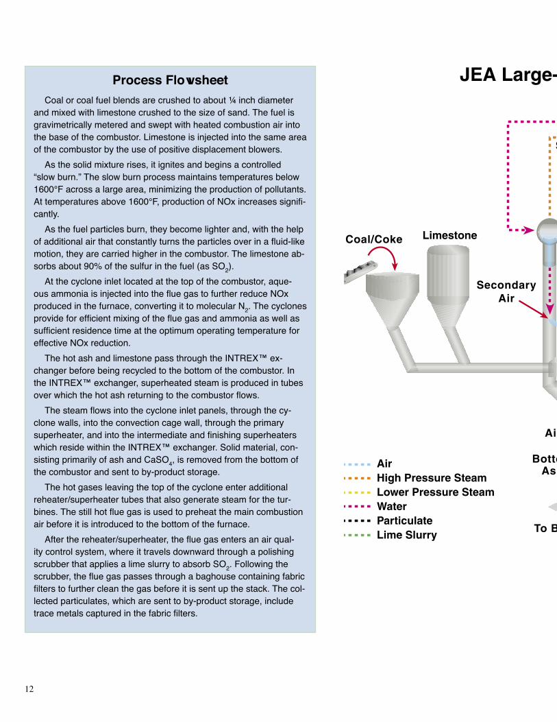
Process FlowsheetCoal or coal fuel blends are crushed to about 1⁄4 inch diameter
and mixed with limestone crushed to the size of sand. The fuel is gravimetrically metered and swept with heated combustion air into the base of the combustor. Limestone is injected into the same area of the combustor by the use of positive displacement blowers.
As the solid mixture rises, it ignites and begins a controlled “slow burn.” The slow burn process maintains temperatures below 1600°F across a large area, minimizing the production of pollutants. At temperatures above 1600°F, production of NOx increases signifi-cantly.
As the fuel particles burn, they become lighter and, with the help of additional air that constantly turns the particles over in a fluid-like motion, they are carried higher in the combustor. The limestone ab-sorbs about 90% of the sulfur in the fuel (as SO2).
At the cyclone inlet located at the top of the combustor, aque-ous ammonia is injected into the flue gas to further reduce NOx produced in the furnace, converting it to molecular N2. The cyclones provide for efficient mixing of the flue gas and ammonia as well as sufficient residence time at the optimum operating temperature for effective NOx reduction.
The hot ash and limestone pass through the INTREX™ ex-changer before being recycled to the bottom of the combustor. In the INTREX™ exchanger, superheated steam is produced in tubes over which the hot ash returning to the combustor flows.
The steam flows into the cyclone inlet panels, through the cy-clone walls, into the convection cage wall, through the primary superheater, and into the intermediate and finishing superheaters which reside within the INTREX™ exchanger. Solid material, con-sisting primarily of ash and CaSO4, is removed from the bottom of the combustor and sent to by-product storage.
The hot gases leaving the top of the cyclone enter additional reheater/superheater tubes that also generate steam for the tur-bines. The still hot flue gas is used to preheat the main combustion air before it is introduced to the bottom of the furnace.
After the reheater/superheater, the flue gas enters an air qual-ity control system, where it travels downward through a polishing scrubber that applies a lime slurry to absorb SO2. Following the scrubber, the flue gas passes through a baghouse containing fabric filters to further clean the gas before it is sent up the stack. The col-lected particulates, which are sent to by-product storage, include trace metals captured in the fabric filters.
Steam TurbineGenerator
PolishingScrubber
Steam
Steam
Coal/Coke
Intrex
LimeSlurry
HeatedAir toBoiler
AirHigh Pressure SteamLower Pressure SteamWaterParticulateLime Slurry
To Byproduct Storage
SecondaryAir
ParticulateControlDevice
Stack
To Byproduct StorageCondenser
CirculatingFluidized-Bed Boiler
Limestone
Cyclone
ReheatExchanger
Economizer
Air Preheater
AirAir
BottomAsh
Feed Water
Air
JEA Large-Scale CFB Combustion Demonstration Project
AmmoniaInjection

12 13
Steam TurbineGenerator
PolishingScrubber
Steam
Steam
Coal/Coke
Intrex
LimeSlurry
HeatedAir toBoiler
AirHigh Pressure SteamLower Pressure SteamWaterParticulateLime Slurry
To Byproduct Storage
SecondaryAir
ParticulateControlDevice
Stack
To Byproduct StorageCondenser
CirculatingFluidized-Bed Boiler
Limestone
Cyclone
ReheatExchanger
Economizer
Air Preheater
AirAir
BottomAsh
Feed Water
Air
JEA Large-Scale CFB Combustion Demonstration Project
AmmoniaInjection
14 15
Natural gas was rejected as an option because northeastern Florida was served by only one pipeline at that time. Orimulsion was not considered seriously because it was not held in high regard by regulatory authorities and it did not offer a cost advantage.
In early 1997, detailed condition assess-ments of Unit 1 and Unit 2 BOP equipment and systems were conducted by JEA and Black & Veatch. The results of that study indicated that both Unit 1 and Unit 2 were good candidates for repowering and were capable of operating for many more years, provided various equipment and system upgrades were made.
In April 1997, JEA approved the project and authorized staff to begin working with Foster Wheeler (FW) on contract negotiations and environmental permitting.
Project OrganizationJEA contracted with Foster Wheeler
Energy Corporation (FWEC) to provide the design and supply of the ACFB boilers. Foster Wheeler USA (FWUSA) provided engineering, procurement, and construction management services for installation of the boilers and for furnishing and erecting the air pollution control systems, stack, limestone preparation system, and ash handling system. Foster Wheeler Environmental Corporation, a subsidiary of FWUSA, was also contracted to provide environmental permitting services.
The remaining portions of the project were implemented by JEA staff, supplemented by Black & Veatch through a pre-existing alli-ance with JEA for engineering services. Pro-curement, construction and related services were provided through other pre-existing
Fluidized Bed CombustionFluidized bed combustion (FBC) is one of the major technologies being de-
veloped under Advanced Electric Power Generation in DOE’s CCT Program. FBC reduces emissions of SO2 and NOx by controlling combustion param-eters and by injecting a sorbent, such as crushed limestone, into the combus-tion chamber along with the coal.
Pulverized coal mixed with the limestone is fluidized on jets of air in the combustion chamber. Sulfur released from the coal as SO2 is captured by the sorbent in the bed to form a solid calcium compound that is removed with the ash. The resultant by-product is a dry, benign solid that can be disposed of easily or used in agricultural and construction applications. More than 90% of the SO2 can be captured in this manner.
At combustion temperatures of 1,400 to 1600°F, the fluidized mixing of the fuel and sorbent enhances both combustion and sulfur capture. The operat-ing temperature range is much lower than that of a conventional pulverized-coal boiler and below the temperature at which thermal NOx is formed. In fact, NOx emissions from FBC units are about 70 to 80% lower than those for conventional boilers. Thus, FBC units substantially reduce both SO2 and NOx emissions. Also, FBC has the capability of using high-ash coal, whereas con-ventional pulverized-coal units must limit ash content in the coal to relatively low levels.
Two parallel paths have been pursued in FBC development—bubbling and circulating beds. Bubbling FBCs use a dense fluid bed and low fluidization velocity to effect good heat transfer and mitigate erosion of an in-bed heat exchanger. Circulating FBCs use a relatively high fluidization velocity that en-trains the bed material, in conjunction with hot cyclones, to separate and recir-culate the bed material from the flue gas before it passes to a heat exchanger. Hybrid systems have evolved from these two basic approaches.
Fluidized bed combustion can be either atmospheric (AFBC) or pressurized (PFBC). As implied by the name, AFBC operates at atmospheric pressure. PFBCs, which operate at pressures 6 to 16 times higher, offer higher effi-ciency by expanding the hot combustion products through a gas turbine and utilizing the steam generated within the combustor to operate a steam turbine. Consequently, operating costs and waste are reduced relative to AFBC, as well as boiler size per unit of power output.
Second-generation PFBC integrates the combustor with a pyrolyzer (coal gasifier) to fuel a gas turbine (topping cycle), and the waste heat is used to generate steam for a steam turbine (bottoming cycle). The inherent efficiency of the gas turbine and waste heat recovery in this combined-cycle mode sig-nificantly increases overall efficiency. Such advanced PFBC systems have the potential for overall thermal efficiencies approaching 50%.
Since PFBCs have not yet been demonstrated on a commercial scale, AFBCs were chosen for the JEA project.

14 15
alliances between JEA and Zachry Con-struction Corporation, Fluor Global Services, W.W. Gay Mechanical Contractor, Inc., and Williams Industrial Services Inc. This work included upgrades of the existing turbine is-land equipment, construction of the receiving and handling facilities for the fuel and reagent required for solid fuel fi ring, upgrading of the electrical switchyard facilities, and construc-tion of an ash management system.
Project StatusEnvironmental permitting work was initi-
ated by FW in the latter part of 1997. This work and associated preliminary engineer-ing proceeded through 1998 and into early 1999. FW began detailed engineering for the boiler island, including the air quality control system, stack, and limestone prepa-ration system, in December 1998. Black & Veatch began detailed engineering for BOP systems, including the fuel handling system, in February 1999. Permits necessary to begin construction were issued in July 1999, with site clearing and construction beginning in August 1999.
Initial synchronization was achieved for Unit 2 on February 19, 2002, and for Unit 1 on May 29, 2002. The JEA project will include two years of demonstration test runs, during which a variety of coal fuel blends will be fi red.
Design Parameters
Fuel Specifi cations Coal Petroleum Coke
Heating Value, Btu/lb >11,600 >13,000
Sulfur, % 0.5-4.5 3.0-8.0
Ash, % 7-15 <3
Volatile Matter, % 30-60 >7
Steam Flow and Conditions Reheat Main
Flow, 1000 lb/hr 1994 1773
Pressure, psi 2,500 548
Temperature, °F 1,000 1,000
JEA plant view from by-product storage area

16 17
Project ObjectivesThe JEA project objectives are (1) to
demonstrate ACFB technology at 297.5 MWe gross (265 MWe net), representing a scale-up from previously constructed facilities; (2) to verify expectations of the technology’s economic, environmental, and technical performance to provide potential users with the data necessary for evaluating large-scale ACFBs as a commercial alterna-tive; (3) to accomplish greater than 90% SO2removal; and (4) to reduce NOx emissions by 60% compared with conventional pulver-ized-coal (PC) fi red boilers not equipped with post-combustion NOx removal.
Initial Performance Results
Emissions Guarantee Value 100% Coal Test 100% Coke Test
SO2, lb/106 Btu <0.15 0.00-0.04 0.03-0.13NOx, lb/106 Btu <0.09 0.04-0.06 0.02CO, lb/106 Btu <0.22 0.044-0.054 0.013-0.015
Particulates, lb/106 Btu <0.011 0.004 0.007PM10, lb/106 Btu <0.011 0.006 0.0044
SO3, lb/hr 1.1 0.43 0.00
Fluoride, lb/hr 0.43 0.29 0.261Lead, lb/hr 0.070 0.015 0.016
Mercury, lb/hr 0.03 0.0027 0.0008VOC, lb/hr 14.0 <0.1 <0.1Opacity, % <10 0.36-1.12 0.21-2.64
Ammonia Slip, ppm 40 0.9 n/a
Boiler ParametersSteam Flow, 1000 lb/hr >1794 1950 1937
Main Steam Temperature, °F >980 996 992Reheat Steam Temperature, °F >980 1001 993
Main Steam - Reheat Steam Temperature, °F <30 6 5
Boiler Effi ciency, % 81.8 88.2 92.0

16 17
Project ScopeThe JEA project involves the construc-
tion and operation of a new 300-MWe ACFB boiler fi red with coal fuel blends to repower an existing steam turbine. ACFB boilers are capable of removing about 90% of the SO2generated, using limestone at a design Ca/S ratio of < 2/1. Greater percentage removal can be achieved by increasing the Ca/S ratio, but the added cost for limestone sorbent becomes prohibitive. To optimize the overall econom-ics and to meet environmental requirements, a polishing scrubber was included in the JEA project. This added feature is required when fi ring higher sulfur fuels, including petroleum coke containing up to 8.0% sulfur.
A key feature of the polishing scrubber is a recycle system which adds fl y ash to the lime sorbent, thereby taking advantage of the unreacted lime in the fl y ash to reduce the amount of fresh lime required. The resulting savings in sorbent and ash disposal costs off-set the added capital and operating costs for the scrubber. In addition, the scrubber offers reductions in emissions of trace elements. The JEA installation represents the fi rst use of a polishing scrubber in conjunction with a CFB in the United States.
As indicated previously, the project includes an SNCR system to reduce NOx emissions to the very low levels required. A new baghouse was installed to achieve over 99.8% reduction in particulate emissions.
In addition to the ACFB combustor itself and the air pollution control systems, new equipment for the project includes an approxi-mately 500-ft high stack as well as handling systems for fuel, limestone, and ash. This includes facilities for delivery of solid fuel to the site by ship. The project also required overhaul and/or modifi cations of existing sys-tems such as the steam turbines, condensate and feedwater systems, circulating water sys-tems, water treatment systems, plant electrical distribution systems, the switchyard, and the plant control systems.
A signifi cant aspect of the JEA project de-sign is that many of the boiler components are at the leading edge of technology, but have been applied successfully in commercial service at least once before. Integrating all these compo-nents while signifi cantly scaling up boiler size is a major project accomplishment.
Wherever possible, existing facilities and infrastructure were used. These include the intake and discharge system for cooling wa-ter, the wastewater treatment system, and the electric transmission lines and towers.
Project activities include engineering and design, permitting, procurement, con-struction, startup, and a twenty-four month demonstration of the commercial feasibility of the technology. During the demonstra-tion test program, Unit 2 will be operated on several different types of coal fuel blends to enhance the viability of the technology. Upon completion of the demonstration test program, Unit 2 will continue in commercial operation. As long as petroleum coke is less expensive than coal, it will continue to be the preferred fuel for the JEA plant.
JEA plant with ship unloading dock in foreground
Fuel unloader at dock

18 19
Advantages of CFB Boilers
Combustion efficiency is improved in circulating fluidized bed (CFB) boilers compared to bubbling bed boilers. This is primarily because the elutriated particles are sepa-rated from the flue gas in cyclone collectors (hot cyclones with vortex finders) and returned to the furnace for further exposure to combustion
temperature and high turbulence. This fact results in an increase of up to 4% in overall combustion ef-ficiency. The particles captured in the cyclone collectors make up the circulating bed material within the “hot loop.” The hot loop is a term given for the circulating path of bed material inside the boiler.
Other advantages of CFB boilers over conventional PC-fired boilers are:• Lower capital cost
• Ability to burn a wide range of low- to high-grade fuels
• Increased sulfur capture with less limestone consumption and low SO2 emissions
• Lower operating temperatures compared with other types of boil-ers, thereby reducing slag forma-tion and excess stack emissions
• Improved heat transfer with the increase in residence time for fuel and limestone
• Lower NOx emissions because of low operating temperatures
Lower operating temperatures mean fewer pollutants and less equipment needed to clean up the combustion process while burning a variety of fuels. The ratios between operating gas velocity and minimum solids entrainment velocity allow turndown ratios as high as four to one. Operation over a wide range of boiler loads is possible without start-ing and stopping burners and auxil-iary equipment.
Schematic diagram of CFB boiler at JEA

18 19
in the fuel. Incomplete combustion results in the formation of carbon monoxide (CO) plus unburned carbon in the solid particles leaving the furnace. In a typical bubbling bed fl uidized boiler, combustion effi ciency can be as high as 92%. This is a good fi gure, but is lower than that achieved by pulverized coal or cyclone-fi red boilers. In addition, some fuels that are very low in volatile matter cannot be completely burned within the available resi-dence time in bubbling bed-type boilers.
Circulating Fluidized Bed BoilersThe need to improve combustion effi -
ciency (which also increases overall boiler effi ciency and reduces operating costs) and the desire to burn a much wider range of fuels has led to the development and application of the CFB boiler. Through the years, boiler suppliers have been increasing the size of these high-effi ciency steam generators. FW has designed (but not built) CFB boilers that are capable of producing 400 MWe of power.
Fluidized Bed Combustion Systems
The ACFB boiler technology selected for the JEA project is an advanced method for utilizing coal and other solid fuels in an environmentally acceptable manner. The low combustion temperature allows SO2 capture via limestone injection while minimizing NOx emissions. The technology provides the capability to burn a wide range of coal fuel blends. Presently, there are two types of fl uidized bed boilers in commercial operation: bubbling bed and circulating bed.
Bubbling Bed BoilersIn the bubbling bed type boiler, a layer of
solid particles (mostly limestone, sand, ash and calcium sulfate) is contained on a grid near the bottom of the boiler. This layer is maintained in a turbulent state as low veloc-ity air is forced into the bed from a plenum chamber beneath the grid. Fuel is added to this bed and combustion takes place. Normally, raw fuel in the bed does not exceed 2% of the total bed inventory. Velocity of the combus-tion air is kept at a minimum, yet high enough to maintain turbulence in the bed. Velocity is not high enough to carry signifi cant quantities of solid particles out of the furnace.
This turbulent mixing of air and fuel results in a residence time of up to fi ve seconds. The combination of turbulent mixing and residence time permits bubbling bed boilers to operate at a furnace temperature below 1650°F. At this temperature, the presence of limestone mixed with fuel in the furnace achieves greater than 90% sulfur removal.
Boiler effi ciency is the percentage of total energy in the fuel that is used to produce steam. Combustion effi ciency is the per-centage of complete combustion of carbon
CFB boiler under construction
continued on page 21

20 21
The Clean Coal Technology ProgramThe Clean Coal Technology
(CCT) Program is a unique partner-ship between the federal govern-ment and industry that has as its primary goal the successful intro-duction of new clean coal utilization technologies into the energy market-place. With its roots in the acid rain debate of the 1980s, the program has met its early objective of broad-ening the range of technological solutions available to eliminate en-vironmental concerns associ-ated with the use of coal for electric power production. As the program has evolved, it has expanded to ad-dress the need for new, high-efficiency power generating technologies that will allow coal to continue to be a fuel option well into the 21st century.
Begun in 1985 and expanded in 1987 consistent with the recommen-dations of the U.S. and Canadian Special Envoys on Acid Rain, the program has been implemented through a series of five nationwide competitive solicitations, or rounds. Each solicitation was associated with specific government funding and program objectives. After five rounds, the CCT Program comprises a total of 38 projects located in 18 states with a total investment value of over $5.2 billion. DOE’s share of the total project costs is about $1.8 billion, or approximately 34% of the total. The projects’ industrial participants (i.e., the non-DOE par-ticipants) are providing the remain-der—about $3.5 billion.
Processes being demonstrated un-der the CCT Program have established a technology base that will enable the nation to meet more stringent energy and environmental goals. Also ready is a new generation of technologies that can produce electricity and other com-modities, such as steam and synthesis gas, at high efficiencies consistent with concerns about global climate change.
Most of the CCT demonstrations are being conducted at commercial scale, in actual user environments, and under circumstances typical of commercial operations. These features allow the potential of the technologies to be evaluated in their intended commercial applications.
Each application addresses one of the following four market sectors:• Advanced electric power generation
• Environmental control devices
• Coal processing for clean fuels
• Industrial applications
Given its programmatic success, the CCT Program serves as a model for other cooperative government/industry
programs aimed at introducing new technologies into the commercial marketplace.
Two follow-on programs have been developed that build on the successes of the CCT Program. The Power Plant Improvement Initiative (PPII) is a cost shared program, pat-terned after the CCT Program, di-rected toward improved reliability and
environmental performance of the nation’s coal-burning power
plants. Authorized by the U.S. Congress
in 2001, the PPII involves eight projects hav-ing a total cost of $95 million. Private sector sponsors are
expected to contribute nearly
$61 million, exceed-ing the 50% private sec-
tor cost sharing mandated by Congress. Most of the PPII projects focus on technologies enabling coal-fired power plants to meet in-creasingly stringent environmental regulations at the lowest possible cost.
The second program is the Clean Coal Power Initiative (CCPI), also patterned on the CCT Program, authorized in early 2002. Valued at $330 million for the initial stage, this initiative will accelerate the commercial deployment of tech-nology advancements that result in efficiency, environmental and economic improvement compared with available state-of-the-art al-ternatives. Proposals submitted under the CCPI are currently being evaluated.

20 21
CFBs offer a number of advantages:
Fuel Flexibility – The relatively low fur-nace temperatures are below the ash softening temperature for nearly all fuels. As a result, furnace design is independent of ash char-acteristics, thus allowing a given furnace to handle a wide range of fuels.
Low SO2 Emissions – Limestone is an effective sulfur sorbent in the temperature range of 1500 to 1700°F. SO2 removal ef-fi ciency of 90% has been demonstrated with good sorbent utilization.
Low NOx Emissions – The combination of low furnace temperatures and staging of air feed to the furnace produces very low NOx emissions.
High Combustion Effi ciency – The long solids residence time in the furnace resulting from the collection/recirculation of solids via the cyclone, plus the vigorous solids/gas con-tact in the furnace caused by the fl uidization air fl ow, results in high combustion effi ciency, even with diffi cult-to-burn fuels.
Characteristics of CFB BoilersIn the furnace of a circulating fl uidized bed
boiler, gas velocity is increased to more than that in a bubbling bed boiler. This increase in velocity causes the dense mixture of solids (fuel, limestone and ash) to be carried up through the furnace. There is a minimum gas entrainment velocity required for the particles to lift and separate (elutriate) and fl ow up, through and out of the furnace.
Reaching this entrainment velocity marks the change from a bubbling bed boiler to a cir-culating bed boiler. At approximately 500°F bed temperature, air fl ows are above minimum and the entrainment velocity is reached.
Solids move up through the furnace at lower velocities than the air and gas mixture. This fact, coupled with the elongated furnace in a CFB boiler and recirculating bed material, allows particle residence times of up to sev-eral minutes in the furnace. During this long residence period, the crushed fuel particles New 500-foot stack in foreground, with inset showing the stack interior
are consumed in the combustion process.
The fuel is reduced in size during the com-bustion process and thoroughly mixed with limestone and the balance of the bed material. This action produces the “fi nes” (small particles of bed material) necessary to have circulating bed material in the “hot loop.” Long residence time, coupled with small particle size and high turbulence, results in a better sulfur removal rate with less limestone than in a bubbling fl uidized bed boiler. In addition, higher gas velocity produces heat transfer rates that are greater than in the bubbling bed.
In normal operation there is no defi ned fi xed bed depth in a CFB boiler. There are different densities of circulating bed material depending on the weight of the particles. Heavy particles stay in the lower region of the furnace. As the height within the furnace increases, the smaller bed particles (less dense) enter the circulation path of the hot loop. When the particles break down enough, they are carried out of the hot loop (circulating path) with the fl ue gas as fl y ash.

22 23
Sulfur Removal in CFB BoilersMost of the sulfur in the fuel combines
chemically with oxygen during the combus-tion process to form SO2 and, to a limited extent, sulfur trioxide (SO3). These sulfur oxides must be removed from the fl ue gas to comply with environmental regulations.
The mechanism for removing SO2 with limestone is as follows:
Calcination of limestone:
CaCO3 + Heat CaO + CO2
Reaction with sulfur oxides (sulfation):
CaO + O2 + SO2 CaSO4
The product, CaSO4, is an inert substance known as gypsum. Limestone continuously reacts with the fuel at normal operating tem-peratures. The sulfation reaction requires that there always be an excess of limestone. The amount of excess limestone required depends on several factors, such as the amount of sulfur in the fuel, the temperature of the bed material in the furnace, and the physical and chemical characteristics of the limestone (reactivity).
The ideal reaction temperature range is 1500 to 1700°F.
There is little limestone reaction when the bed temperature is below 1500°F or above 1700°F. Within the optimum temperature range, about 90% of the SO2 can be re-moved at an acceptable Ca/S ratio. Outside this temperature range, signifi cant increases in limestone feed rate are required to maintain emission levels within regulated limits.
The CFB bed material typically contains limestone products as the predominant com-ponent, with smaller amounts of fuel, ash and impurities (for example, rocks or tramp iron). Calcium oxide content rises with decreasing fuel sulfur content and high removal rates. The ash content increases with higher ash fuels and those that are less friable, i.e., brittle.
Fresh limestone enters the furnace and, at the normal operating temperature, calcines by liberating CO2. It then absorbs SO2 from the burning fuel that sulfates the limestone, converting limestone to gypsum. In the calcin-ing stage, limestone is physically weak and is easily decrepitated (crumbled) into dust and carried out of the bed (elutriated) by the furnace draft.
With a sulfur content in the fuel of 2.5% or more, enough SO2 is produced during com-bustion that the limestone can readily sulfate (combine with the SO2). This strengthens the limestone and reduces loss of limestone from decrepitation and elutriation. A low sulfur content can lead to loss of limestone through attrition. This loss must be compensated for by increasing limestone feed to maintain bed inventory and SO2 capture. Gypsum and some excess limestone are carried out of the CFB furnace and trapped by the downstream fl ue gas cleanup equipment.

22 23
Demonstration Test Program
The demonstration test program will be conducted in accordance with the plan developed in coordination with DOE. The test program consists of the following major components.
Operational Testing will be performed to:
• Demonstrate unit functionality
• Establish initial operating, maintenance and inspection criteria
• Establish constraints related to dispatch of the unit
• Demonstrate continuous full- and part-load capability and performance
Operational testing includes a series of op-erability, reliability, and performance tests.
Operability involves tests of cold startups, warm startups, hot restarts, dispatch, mini-mum stable load, and operation at maximum continuous rating.
Reliability testing includes availability, capacity factor, and forced outage rate.
Performance testing will be conducted in conjunction with fuel fl exibility testing, which involves burning four different fuels and fuel blends. The specifi c fuels to be tested are as follows:
• 100% Pittsburgh No. 8 high-sulfur coal
• 90% petroleum coke and 10% Pittsburgh No. 8 high-sulfur coal
• 50% petroleum coke and 50% Pittsburgh No. 8 high-sulfur coal
• 100% Illinois No. 6 high-sulfur coal
Fuel Flexibility Testing includes boiler capacity and controllability, load follow-ing capability, bed/cyclone agglomeration potential, and air quality control system performance.
Long Term Durability Testing consists of reviewing signifi cant maintenance issues experienced with major equipment through-out the demonstration period.
Operating ResultsThe JEA Unit 2 CFB boiler has operated at
full load, achieving rated output in May 2002. The unit can maintain operation on both coal and coal fuel blends. However, satisfactory operation on 100% petroleum coke has not yet been demonstrated. One major problem when operating on 100% petroleum coke has been plugging in the hot gas path, specifi -cally in the cyclone and the INTREX™ heat exchanger. Steps are being taken to remedy this situation.
Initial results indicate that the JEA plant is capable of meeting emissions guarantees when operating on both coal and coal fuel blends.
Interior of fuel storage dome

24 25
AwardsThe JEA project received the 2002 Pow-
erplant Award from Power magazine. This award recognizes outstanding achievement in “the development of a successful repowering strategy for converting existing oil/gas-fi red steam plants to solid fuels to increase effi -ciency while reducing both emissions and the cost of electricity.”
Bob Dyr, JEA’s Boiler Island Project Man-ager, was presented the Engineer of the Year award by the Florida Engineers Society in 2002 for outstanding technical achievement, on behalf of the project team.
Commercial Applica tions
ACFB technology has potential applica-tion in both the industrial and utility sectors, for use in repowering existing plants a well as in new facilities. ACFB is attractive for both baseload and dispatchable power applications because it can be effi ciently turned down to as low as 25% of full load. While the effi ciency of ACFB is on a par with conventional PC-fi red plants, the advantage of ACFB is that coal of any sulfur or ash content can be used, and any type or size unit can be repowered.
In repowering applications, an existing plant area is used, and coal- and waste-handling equipment as well as steam turbine equip-ment are retained, thereby extending the life of the plant.
In its commercial confi guration, ACFB technology offers several potential benefi ts compared with conventional PC-fi red sys-tems:
• Lower capital costs
• Reduced SO2 and NOx emissions at lower cost
• Higher combustion effi ciency
• A high degree of fuel fl exibility, including use of renewable fuels
• Dry, granular solid by-product material that is easily disposed of or sold.
Recently, two other commercial scale ACFB projects in the U.S. have been an-nounced, one at Reliant Energy's Seward Station in Pennsylvania and the other at Tractabel's Red Hills Station in Missis-sippi.
ConclusionsThe JEA Large-Scale CFB Combustion
Demonstration Project is demonstrating the commercial ap plication of this advanced technology for generating electricity. The two boilers at the Northside Station are the largest CFBs in the world burning coal fuel blends. Despite the large furnace size, solids distribution is good, lending confi dence to the CFB design.
Power production from each boiler on coal feed meets the target goal of 297.5 MWe gross (265 MWe net). Emissions of atmospheric pol-lutants are below the stringent requirements set for the project.
JEA receives the Power magazine 2002 Powerplant award. On hand for the award ceremony were (left to right): Mike High-tower, JEA's Board Chairman; Joey Dun-can, JEA's Project Manager; the Honorable Corrine Brown, U.S. House of Representa-tives; Rita Bajura, Director of U.S. DOE's National Energy Technology Laboratory; and Bob Schwieger, Power magazine con-sulting editor

24 25
BibliographyP.T. Nielsen, J.L. Hebb, R. Aquino, and S.L. Darling, “Large-Scale CFB Combus-tion Demonstration Project,” Sixth Clean Coal Technology Con ference (Reno NV), May 1998.
U.S. Department of Energy, Clean Coal Tech-nology Demonstration Program -- Program Update 2000, July 2002.
R. Dyr and G. Graham, “The Northside 1 and 2 Repowering Project: An Overview,” 7th Foster Wheeler Fluidized Bed Customer Conference, San Diego CA, August 14-16, 2002.
R. Schwieger, “Northside’s CFB Repower-ing Halves Power Cost, Reduces Emissions,” Power, September 2002, p. 20.
R.A. Dyr and A.L. Compaan, “JEA Northside Repowering: 2002 Powerplant of the Year,” presented at FMEA 2002 Energy Connections Workshop and Trade Show, St. Petersburg FL, October 15-17, 2002.
JEA, “Public Design Report for the JEA Large-Scale CFB Combustion Demonstra-tion Project,” March 2003.

26 27
List of Acronyms and AbbreviationsACFB ........................... atmospheric circulating fl uidized bed
AFBC ........................... atmospheric fl uidized bed combustor
AQCS ........................... air quality control system
BOP.............................. balance of plant
Btu ................................ British thermal unit
CaCO3 .......................... calcium carbonate
CaO .............................. calcium oxide
Ca(OH)2........................ calcium hydroxide
CaSO4........................... calcium sulfate
CAAA........................... Clean Air Act Amendments of 1990
CCPI............................. Clean Coal Power Initiative
CCT.............................. Clean Coal Technology
CFB .............................. circulating fl uidized bed
CO2............................... carbon dioxide
CRT .............................. cathode ray tube
DCS.............................. distributed control system
DOE ............................. U.S. Department of Energy
EPA............................... U.S. Environmental Protection Agency
FBC .............................. fl uidized bed combustion
FF ................................. fabric fi lters
Stack shortly after 9/11/2001

26 27
kWh.............................. kilowatt hour
micron .......................... one millionth of a meter
MCR............................. maximum continuous rating
MgCO3 ......................... magnesium carbonate
Mg(OH)2 ...................... magnesium hydroxide
MWe............................. megawatts of electric power
MWh ............................ megawatt hours of electric power
NETL............................ National Energy Technology Laboratory
NOx.............................. nitrogen oxides
PC................................. pulverized coal
PFBC............................ pressurized fl uidized bed combustor
PLC .............................. programmable logic controller
PM................................ particulate matter
PM10 ............................. particulate matter having a diameter of 10 microns (µm) or less
PPII............................... Power Plant Improvement Initiative
psig ............................... pressure, pounds per square inch (gauge)
SDA.............................. spray dryer absorber
SO2 ............................... sulfur dioxide
SO3 ............................... sulfur trioxide
tph................................. tons/hr
VOC ............................. volatile organic compound
wt % ............................. percent by weight
Sunset at JEA

28
Contacts for CCT Projects and U.S. DOE CCT ProgramParticipant ContactJoey V. Duncan
JEA Project General Manager(904) [email protected]
U.S. Department of Energy ContactsGeorge Lynch
U.S. Department of Energy, FE-24Germantown MD 20874-1290(301) 903-9434(301) 903-2713 fax
Jerry L. Hebb, P.E.
Project ManagerNational Energy Technology LaboratoryP.O. Box 10940Pittsburgh PA 15236-0940(412) 386-6079(412) 386-4775 [email protected]
This report is available on the Internet at www.netl.doe.gov. Select Links, then Clean Coal Technology Compendium
NETL web page on FBC:www.netl.doe.gov/coalpower/combustion
JEA website:www.jea.com
To Receive Additional Information
To be placed on the Department of Energy’s distribution list for future information on the Clean Coal Tech-nology Program, the demonstra-tion projects it is financing, or other Fossil Energy Programs, please contact:
Robert C. PorterDirector, Office of CommunicationU.S. Department of Energy, FE-51000 Independence Ave SWWashington DC 20585(202) 586-6503(202) 586-5146 [email protected]
Otis MillsPublic Information OfficeU.S. Department of EnergyNational Energy
Technology LaboratoryP.O. Box 10940Pittsburgh PA 15236-0940(412) 386-5890(412) 386-6195 [email protected]
