the leonardo building - · pdf filethe leonardo building ... • bs 12056-3:2000 gravity...
TRANSCRIPT
The Leonardo Building
Project No. 14-12
Drainage Specification
DMW-1412-DRS-P01 August 2014
Produced for Bowmer & Kirkland
Contents
R12 DRAINAGE BELOW GROUND 3
GENERAL PROJECT INFORMATION ..................................................................................................... 3
GENERAL DRAINAGE SPECIFICATION INFORMATION ....................................................................... 4
SYSTEM PERFORMANCE ....................................................................................................................... 5
PRODUCTS............................................................................................................................................... 6
EXECUTION ............................................................................................................................................ 10
COMPLETION ......................................................................................................................................... 15
APPENDIX A 17
REVISION HISTORY
Rev Date Purpose/Status Document Ref. Comments
P01 01/09/2014 Info DMW-1412-DRS-P01
QUALITY CONTROL:
Prepared by: Approved by:
Malcolm Archer Associate
Gareth Davies Director
R12 DRAINAGE BELOW GROUND
GENERAL PROJECT INFORMATION
Project Name: The Leonardo Building
Employer Name: Bowmer & Kirkland Address: 1210 Arlington Business Park, Reading RG7 4TY Tel. no: 0118 965 7677 E-mail: [email protected] Contact name: Nick Harding
Engineer Name: Davies Maguire + Whitby Address: 20 Flaxman Terrace, London, WC1H 9AT Tel. no: 020 7388 9406 E-mail: [email protected] Contact name: Malcolm Archer
Contract administrator (CA) Name: Bowmer & Kirkland Address: 1210 Arlington Business Park, Reading RG7 4TY Tel. no: 0118 965 7677 E-mail: [email protected] Contact name: Nick Harding Other named Parties to the Contract: Architect: tpbennett M&E: Derry
Description of the Project Works The proposed development is a four storey steel framed building with RC metal deck composite floors from first floor and above. The ground floor is reinforced concrete flat slabs spanning between reinforced strip footings, There is no basement, but sumps and lift pits do project below the ground floor slab.
To be read with Preliminaries/General conditions. Ensure that the local Authority and Building Control are fully aware for the proposed installation
that they have all the necessary documentation and that approval has been gained before commencement of works on site. Design: Complete the design of the below ground drainage system in accordance with:
• Building Regulations (Current Edition) – Approved Document Part H;
• BS EN 752:2008 Drain and sewer systems outside buildings;
• BS 12056-3:2000 Gravity drainage systems inside buildings. Roof drainage, layout and calculation;
• BS EN 1610:1998 Construction and testing of drains and sewers.
GENERAL DRAINAGE SPECIFICATION INFORMATION 100 EXISTING DRAINS: - Before starting work, check invert levels and positions of existing discharge inspection
chambers/manholes and existing watercourses against information shown on drawings and CCTV report and advise any discrepancies to the Engineer. Re CCTV-survey drainage systems following site demolition where systems are to be retained and re-used (for confirmation of condition and suitability for retention).
- Note – significant existing drainage is to be retained and re-used - Adequately protect existing drains and maintain clear and normal operation during construction.
102 WORKMANSHIP:
- Comply with BS 8000: Part 14. 104 APPROVALS
- Ensure that the Local Authority (Thames Water & Environment Agency) and Building Control are fully aware of the proposed installation, that they have all the necessary documentation, and that approval has been gained before commencement of works on site. Ensure Section 106 Discharge Consent is applied for and in place prior to practical completion and use of the building/development.
106 IN-SITU CONCRETE:
- Unless specified otherwise, in-situ concrete for use in drainage below ground to be to BS 5328 as shown in the table below or an equivalent or higher grade mix subject to approval:
Application Concrete mix
Trench backfill C10, ST2 or GEN1 Structural protection to pipelines Surrounds to chambers, separators and tanks Concrete bagwork Bed and surround to drainage channels
C20, ST4 or GEN3
Plain concrete in structures (eg manhole bases) C20, ST4 or GEN3 with Class 3 SR cement
Reinforced concrete (eg. chamber cover slabs) RC30
- Different mixes may be used for different parts of the drainage work. - Wearing screeds (previously known as “high strength toppings” or “granolithic finish”) for benching
to be to BS 4483-2, class AR3/Ws or AR3/DF or better. -
107 AS BUILT RECORDS - Keep marked up copies of drawings showing As Built information. - Maintain records of inspection and test.
108 REDUNDANT DRAINS The following methods should be used as appropriate:
- The drain run should be removed in its entirety and sealed at the manhole/branch connection.
- The drain run should be filled with a weak mix concrete or cement grout to prevent collapse (this may not be necessary if the drain is under the building as it will be encased in concrete).
- The drain can be sealed at either end by the use of concrete plugs. - Extend the drain to above ground level and seal with proprietary blank caps.
It will not be necessary to extend the drain above flood level of fittings if the redundant drain is
effectively sealed and made watertight, this is also essential to prevent foul smells from entering the building.
110 BELOW GROUND DRAINAGE SYSTEMS - Surface water and rainwater drainage sources: Hard-standing and collection systems from
building roof areas. - Foul drainage sources: Commercial Building(s). - Pipes, bends and junctions: at change of flow direction Accessories: Where required by the drainage systems, as per Manufacturers recommendation and the Drainage Specification. - Manholes, inspection chambers and traps: at change of flow direction, branches connections and
where an access is required for maintenance and cleaning. Accessories: Where required by manufacturers recommendation and the Drainage Specification, as per manufacturers recommendations. - Discharge: Thames Water Public Utility Sewerage systems.
SYSTEM PERFORMANCE 211 DESIGN - BELOW GROUND DRAINAGE SYSTEMS - Design: Complete the design of the below ground drainage system in accordance with BS EN
752, BS EN 1295-1 and BS EN 1610. - Proposals: Submit drawings, technical information, calculations and manufacturers’ literature.
PRODUCTS 311 CONNECTORS - Material and standard: Plastics to BS 4660 and Kitemark certified. - Manufacturer and reference: Hepworth or similar approved. 313 INTERNAL TRAPPED GULLIES (Equipment/Refuse Stores) - Material: Cast Iron to BS EN 1561 - Manufacturer and reference: Wade G604 or Similar approved. - Cover: Nickel Bronze Grading. Wade L2104 to be approved by Architect. - Outlet sizes: 100mm. 614W YARD GULLY CLAY (Open Refuse Stores & Service Areas)
- Manufacturer and reference: Hepworth RGP6 (with removable grate) with silt bucket IBP3 or equal approved
- Install in accordance with manufacturer’s recommendations - Bed and surround with minimum 15mm concrete to R12/106W
314R INTERNAL SHOWER DRAINS
- Material: To architects Specification & details - Manufacturer and reference: To Architect’s specification. - Cover: To Architect’s Specification. - Outlet sizes: 100mm trapped with high-invert cast iron 87.5◦ drainage trap.
315W DRAINAGE CHANNEL (for External Car Parking & Hard-standing areas):
- Manufacturer and reference(s): Aco Q-Max 900 integral attenuation and storm water collection system or similar approved (refer to drainage layouts drawings for location)
- Grate: Ductile Iron slotted channel – Facta D400 Loading - Bed and surround with min 150mm of concrete to clause R12/106W - Connect to drain using proprietary roddable sump unit with silt bucket - Install in accordance with manufacturer’s recommendations
622W ROAD GULLY:
- Precast concrete gully pot to BS 5911-230, kitemark certified, trapped with stopper in rodding eye, 450 dia by 900 deep
- Bed on 150mm of concrete and surround with 100mm of concrete - Set grating frame on 300mm depth of gully cover slabs to BS 5911-230, kitemark certified, or
225mm wide engineering brickwork - Bed and haunch grating frame on 1:3 cement:sand mortar. Set top of grating 5mm below
adjacent surface level. - Grating to BS EN 124, kitemark certified, class D400 with a minimum waterway area of 950 cm²,
as St Gobain Waterway 1000. 329 PIPES, BENDS AND JUNCTIONS - SUPPLY - Pipes and fittings: From same manufacturer for each pipeline. 332 PIPES, BENDS AND JUNCTIONS - CAST IRON (DRAINS WITHIN/UNDER THE BUILDING) - Standard: To BS EN 598 & BS EN 877, with flexible joints, Kitemark certified. - Manufacturer and reference: St Gobain Timesaver or similar approved. - Sizes: DN100 & DN150. - Additional corrosion protection: None. - Jointing type: Flexible Bolted Mechanical Joints. 336 PIPES, BENDS AND JUNCTIONS - CLAY - FLEXIBLE JOINTS (EXTERNAL DRAINS ONLY –
NOT WITHIN/UNDER THE BUILDING) - Pipes, bends and junctions: Vitrified clay to BS EN 295-1, with flexible joints, Kitemark certified. - Manufacturer and reference: Hepworth or similar approved - Bedding class: Class Z under building slab, in car parking and access roads where cover is less
than 750mm. Class S in vehicle access areas where cover is between 0.75m and 1.2m, and in pedestrian/paving areas where cover is less than 0.45m. Otherwise, use Class B.
- Assumed type of subsoil: as per geotechnical report. - Warning marker tape: Not required
357 CONNECTORS – SADDLE (TBC with TW for connection to public sewer)
- WRc approved flexible saddle as Flex-Seal or equivalent - Main pipe to be diamond drilled - Install in accordance with the manufacturer’s instructions - Rigid saddles are not acceptable.
359 FLEXIBLE COUPLINGS
- Standard: To BS EN 295-4 or WIS 04-41-01 and Kitemark certified, or Agrément - Manufacturer and reference(s): Flex-Seal SC180, SC275 (TBC with M&E engineer) - Ensure that the ends of pipes to be joined are cleanly cut and square. - Ensure that outer surfaces of pipes to be joined are clean and smooth. Where necessary, e.g. on
concrete or iron pipes, smooth out mould lines and/or apply a cement grout over the sealing area. 365 PUDDLE FLANGES - Manufacturer and reference: To specialist subcontractor’s details. Note – Alternative proprietary hydrophilic seals may be utilised – refer to drainage details for
position/location requirements. 369 RESIN CEMENT MORTAR FOR JOINTING RIGID CLAY PIPELINES
- Manufacturer and reference: to manufacturer’s requirements. 379 WARNING MARKER TAPES – To Building Services Engineers specifications 401 INSPECTION CHAMBERS - PLASTICS - Plastics inspection chambers: To BS 7158, Kitemark certified, from same manufacturer as pipes - Manufacturer and reference: Hepworth Polypropylene Inspection Chamber (PPIC) ref. SPIC1/1 or
SPIC2/1 for DN100 and SPIC1/2 for DN100 + DN150 or similar approved; - Bedding: as connecting drains; - Surround: Below slabs: Minimum 150 mm concrete, mix as specified by the Structural Engineers;
externally: same material as connected drains, well compacted, with 225 mm deep x 150 mm wide concrete cover support collar, mix as specified under Generally.
- Backfilling: as connecting drains; - Access covers and seating: refer to manhole schedule, orientation and setting-out of access
covers to be detailed/confirmed by the Architect. Accessories: Proprietary access hatch/panel within floor finish to match flooring arrangements
required over sealed manhole cover to Architect specification and details. 402 MANHOLES AND INSPECTION CHAMBERS - CONCRETE UP TO 6 METRES DEEP. - In situ concrete bases: 225 mm thick plain concrete. - Standards: - To BS 5911-3 and BS EN 1917 and Kitemark certified; or - To BS 5911-4 and BS EN 1917. - Manufacturer: FP McCann or similar approved; - Shape: Circular; - Sizes: Sizes DN1050 & DN1200 - Cement type and content: as specified under Generally; - Chamber sections: - Product reference: refer to FP McCann specification; - Jointing type: mortar, proprietary bitumen or resin mastic sealant - Cover slabs: - Product reference: refer to FP McCann specification - Thickness: Vary (refer to manufacturer’s specifications) - Loading grades to BS EN 124: Heavy duty - Openings: To suit access covers. - Steps: Double, Class 1, to BS EN 13101. Bed in joints to all chambers over 900 mm deep at 300
mm vertical centres staggered 300 mm horizontally, with lowest step not more than 300 mm above benching and top step not more than 450 mm below top of cover.
- In situ concrete surround: 150 mm minimum thickness, mix as specified under Generally.
- Channels, branches and benching: Vitrified clay half round channel with ¾ section bends with high strength concrete benching with 20mm wearing screed trowelled smooth or formed in concrete.
- Access covers and seating: refer to manhole schedule, orientation to be confirmed by the Architect.
410 LIGHT LIQUID SEPARATOR: (LLP 01)
- Manufacturer and reference: Conder Class 1 By-Pass Separator - Model ref: CNSB20s/21 - Capacity: 2000 Litres (silt) - Design flow to separator: 160.0 litres/second - Area drained: - Inlet pipe: 375mm - Outlet pipe: 375mm - Vent pipes: 75mm - Concrete surround: To Engineers Details - Ancillaries: Separator to be provided with integral oil level probe and remote mains power fed
audible/visual high-level warning oil alarm monitoring arrangements - Cover: Steelway ref: X6333E - 750x750mm Bripave Infill Cover -
430 ATTENUATION RESERVOIR/TANK (SURFACE WATER) - Manufacturer – Environmental Sustainable Solutions or similar approved - Product – Versa void or similar approved - Unit Size – Refer to drainage drawings - Independent Compressive Strength = 475 KN/m2 Underground tanks in accordance with CIRIA C697 and C680 design requirements.
- Installation drawing reference: Refer to drainage drawing/details and manufacturer’s installation requirements and guidelines.
- In-situ concrete cover and base: 150 mm thick plain concrete, mix as specified under generally, cover slab reinforced to Engineers requirements.
- Air Vent and maintenance access to be in accordance with manufacturer’s recommendations. - Installation of Tuflex or similar approved Waterproofing membrane and Geotextile or similar
approved protection fleece to be in accordance with manufacturer’s recommendation. 435W FLOW CONTROL DEVICE:
- Located within manhole ref: SWMH6 (outfall manhole) and positioned down-stream of attenuation tank.
- Wall-Mounted orifice plate Flow Control Device positioned on purpose-made guide rails with lifting chain and fixing eye. Manufacturer: purpose-made for application Size: 85mm diameter smooth round orifice Material: Grade 304 Stainless Steel Discharge RATE: 76.0 l/s Installed in outfall manhole to manage attenuation storm water flows off site
439 MANHOLE STEPS - Standard: To BS EN 13101. - Type: Double Class 1 - Material: Cast Iron
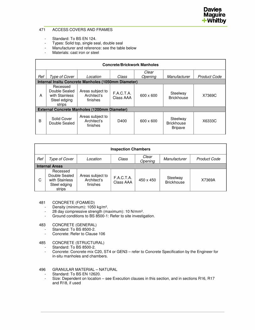
471 ACCESS COVERS AND FRAMES - Standard: To BS EN 124. - Types: Solid top, single seal, double seal
- Manufacturer and reference: see the table below - Materials: cast iron or steel
Concrete/Brickwork Manholes
Ref Type of Cover Location Class Clear
Opening Manufacturer Product Code
Internal Insitu Concrete Manholes (1050mm Diameter)
A
Recessed Double Sealed with Stainless Steel edging
strips
Areas subject to Architect’s
finishes
F.A.C.T.A. Class AAA
600 x 600 Steelway
Brickhouse X7369C
External Concrete Manholes (1200mm Diameter)
B
Solid Cover Double Sealed
Areas subject to Architect’s
finishes
D400
600 x 600
Steelway
Brickhouse Bripave
X6333C
Inspection Chambers
Ref Type of Cover Location Class Clear
Opening Manufacturer Product Code
Internal Areas
C
Recessed Double Sealed with Stainless Steel edging
strips
Areas subject to Architect’s
finishes
F.A.C.T.A. Class AAA
450 x 450 Steelway
Brickhouse X7369A
481 CONCRETE (FOAMED) - Density (minimum): 1050 kg/m². - 28 day compressive strength (maximum): 10 N/mm². - Ground conditions to BS 8500-1: Refer to site investigation. 483 CONCRETE (GENERAL) - Standard: To BS 8500-2. - Concrete: Refer to Clause 106 485 CONCRETE (STRUCTURAL) - Standard: To BS 8500-2. - Concrete: Concrete mix C20, ST4 or GEN3 – refer to Concrete Specification by the Engineer for
in-situ manholes and chambers. 496 GRANULAR MATERIAL – NATURAL - Standard: To BS EN 12620. - Size: Dependent on location – see Execution clauses in this section, and in sections R16, R17
and R18, if used
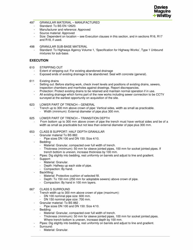
497 GRANULAR MATERIAL – MANUFACTURED - Standard: To BS EN 12620.
- Manufacturer and reference: Approved - Source material: Approved - Size: Dependent on location – see Execution clauses in this section, and in sections R16, R17
and R18, if used. 498 GRANULAR SUB-BASE MATERIAL - Standard: To Highways Agency Volume 1, ‘Specification for Highway Works’, Type 1 Unbound
mixtures for sub-base.
EXECUTION 610 STRIPPING OUT - Extent of stripping out: For existing abandoned drainage - Exposed ends of existing drainage to be abandoned: Seal with concrete (general). 611 Existing drains - Setting out: Before starting work, check invert levels and positions of existing drains, sewers,
inspection chambers and manholes against drawings. Report discrepancies. - Protection: Protect existing drains to be retained and maintain normal operation if in use. - All existing drainage which forms part of the new works including sewer connection to be CCTV
surveyed at the earliest opportunity on acquisition of the site. 623 LOWER PART OF TRENCH – GENERAL - Trench up to 300 mm above crown of pipe: Vertical sides, width as small as practicable. - Width (minimum): External diameter of pipe plus 300 mm. 625 LOWER PART OF TRENCH – TRANSITION DEPTH
- From bottom up to 300 mm above crown of pipe the trench must have vertical sides and be of a width as small as practicable but not less than external diameter of pipe plus 300 mm.
653 CLASS B SUPPORT: HALF DEPTH GRANULAR - Granular material To BS 882. - Pipe sizes DN 100 and DN 150: Size 4/10. - Bedding: - Material: Granular, compacted over full width of trench. - Thickness (minimum): 50 mm for sleeve jointed pipes, 100 mm for socket jointed pipes. If
trench bottom is uneven, increase thickness by 100 mm. - Pipes: Dig slightly into bedding, rest uniformly on barrels and adjust to line and gradient. - Support: - Material: Granular. - Depth: Halfway up each side of pipe. - Compaction: By hand. - Backfilling: - Material: Protective cushion of selected fill. - Depth: To 150 mm (250 mm for adoptable sewers) above crown of pipe. - Compaction: By hand in 100 mm layers. 667 CLASS S SURROUND - Trench width up to 300 mm above crown of pipe (maximum): - DN 100 nominal pipe size: 600 mm. - DN 150 nominal pipe size: 700 mm. - Granular material: To BS 882 . - Pipe sizes DN 100 and DN 150: Size 4/10. - Bedding: - Material: Granular, compacted over full width of trench. - Thickness (minimum): 50 mm for sleeve jointed pipes, 100 mm for socket jointed pipes.
Where trench bottom is uneven, increase depth by 100 mm. - Pipes: Dig slightly into bedding, rest uniformly on barrels and adjust to line and gradient. - Surround: - Material: Granular.
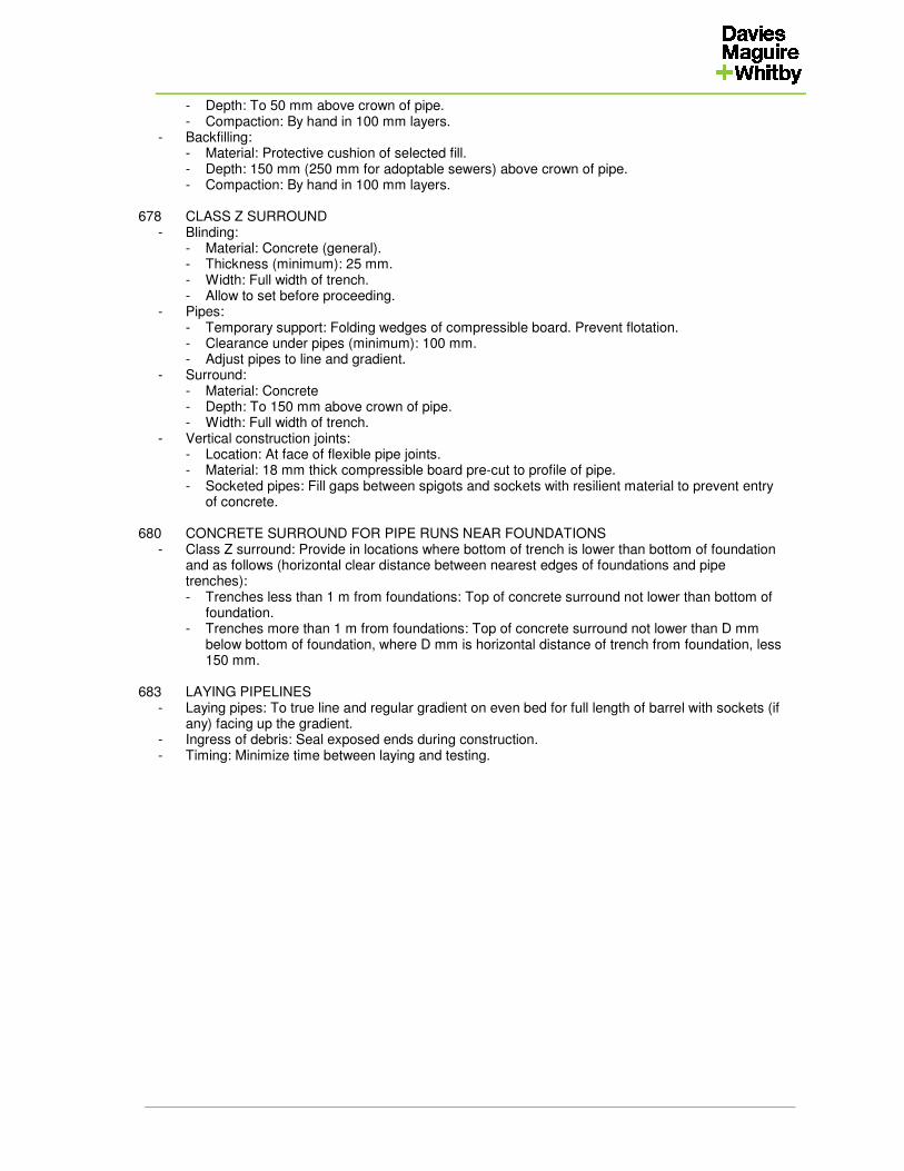
- Depth: To 50 mm above crown of pipe. - Compaction: By hand in 100 mm layers. - Backfilling: - Material: Protective cushion of selected fill. - Depth: 150 mm (250 mm for adoptable sewers) above crown of pipe. - Compaction: By hand in 100 mm layers. 678 CLASS Z SURROUND - Blinding: - Material: Concrete (general). - Thickness (minimum): 25 mm. - Width: Full width of trench. - Allow to set before proceeding. - Pipes: - Temporary support: Folding wedges of compressible board. Prevent flotation. - Clearance under pipes (minimum): 100 mm. - Adjust pipes to line and gradient. - Surround: - Material: Concrete - Depth: To 150 mm above crown of pipe. - Width: Full width of trench. - Vertical construction joints: - Location: At face of flexible pipe joints. - Material: 18 mm thick compressible board pre-cut to profile of pipe. - Socketed pipes: Fill gaps between spigots and sockets with resilient material to prevent entry
of concrete. 680 CONCRETE SURROUND FOR PIPE RUNS NEAR FOUNDATIONS - Class Z surround: Provide in locations where bottom of trench is lower than bottom of foundation
and as follows (horizontal clear distance between nearest edges of foundations and pipe trenches):
- Trenches less than 1 m from foundations: Top of concrete surround not lower than bottom of foundation.
- Trenches more than 1 m from foundations: Top of concrete surround not lower than D mm below bottom of foundation, where D mm is horizontal distance of trench from foundation, less 150 mm.
683 LAYING PIPELINES - Laying pipes: To true line and regular gradient on even bed for full length of barrel with sockets (if
any) facing up the gradient. - Ingress of debris: Seal exposed ends during construction. - Timing: Minimize time between laying and testing.

685 JOINTING PIPELINES - Connections: Durable, effective and free from leakage. - Junctions, including to differing pipework systems: With adaptors intended for the purpose. - Cut ends of pipes: Clean and square. Remove burrs and swarf. Chamfer pipe ends before
inserting into ring seal sockets. - Jointing or mating surfaces: Clean and, where necessary, lubricate immediately before assembly. - Allowance for movement: Provide and maintain appropriate clearance at ends of spigots as fixing
and jointing proceeds. - Jointing material: Do not allow to project into bore of pipes and fittings. 687 CONCRETE SURROUND FOR CROSSOVERS - Class Z surround: Provide where two pipelines (other than plastics pipes) cross with less than 300
mm separation. - Extent, on both pipes: 1 m centred on the crossing point, and beyond as necessary to come
within 150 mm of nearest flexible joints. 689 PIPELINES PASSING THROUGH STRUCTURES - Pipelines that must be cast in or fixed to structures (including manholes, catch-pits and inspection
chambers): Provide 600 mm long rocker pipes adjacent to the external face of the structure (or both faces where appropriate, e.g. walls to footings), with flexible joints at both ends.
- Distance to rocker pipe from structure (maximum):150 mm. - Provision for movement for pipelines that need not be cast in or fixed to structures (e.g. walls to
footings): - Rocker pipes as specified above; or - Openings in the structures to give 50 mm minimum clearance around the pipeline. Closely fit a
rigid sheet to each side of opening to prevent ingress of fill or vermin. 695 BACKDROP PIPES OUTSIDE MANHOLE WALLS
- Encase with not less than 150 mm of concrete as specified under Generally. All excavation beneath the backdrop pipe and its surround must be replaced with concrete.
697 INSTALLING FLEXIBLE COUPLINGS - Ends of pipes to be joined: Cut cleanly and square. - Outer surfaces of pipes to be joined: Clean and smooth. Where necessary, e.g. on concrete or
iron pipes, smooth out mould lines and/ or apply a cement grout over the sealing area. - Clamping bands: Tighten carefully to make gastight and watertight seals. 699 CONNECTIONS TO SEWERS - General: Connect new pipework to existing adopted sewers to the requirements of the adopting
authority or its agent. 705 INITIAL TESTING OF PIPELINES - Before testing: - Cement mortar jointing: Leave 24 h. - Solvent welded pipelines: Leave 1 h. - Method: Block open ends of pipelines to be tested and pressurise. Air test short lengths to BS EN
1610. 711 TRENCH SUPPORTS - Removal of trench supports: Sufficient to permit compacted filling of all spaces. 715 BACKFILLING TO PIPELINES - Backfilling above top of surround or protective cushion: Material excavated from trench,
compacted in layers 300 mm (maximum) thick. - Heavy compactors: Do not use before there is 600 mm (total) of material over pipes. 718 BACKFILLING OVER CONCRETE - Minimum times from placing concrete: - Backfilling generally: 24 h. - Heavy compactors and traffic loads: 72 h. 720 BACKFILLING UNDER ROADS AND PAVINGS
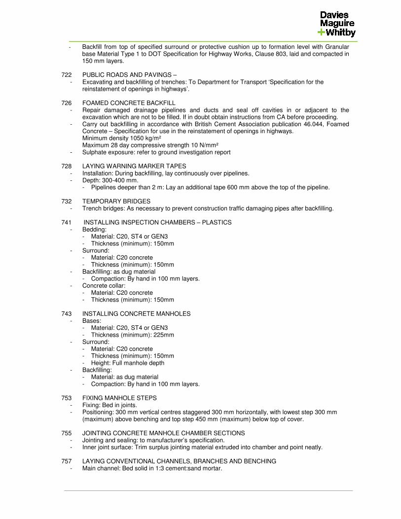
- Backfill from top of specified surround or protective cushion up to formation level with Granular base Material Type 1 to DOT Specification for Highway Works, Clause 803, laid and compacted in 150 mm layers.
722 PUBLIC ROADS AND PAVINGS – - Excavating and backfilling of trenches: To Department for Transport ‘Specification for the
reinstatement of openings in highways’. 726 FOAMED CONCRETE BACKFILL - Repair damaged drainage pipelines and ducts and seal off cavities in or adjacent to the
excavation which are not to be filled. If in doubt obtain instructions from CA before proceeding. - Carry out backfilling in accordance with British Cement Association publication 46.044, Foamed
Concrete – Specification for use in the reinstatement of openings in highways. Minimum density 1050 kg/m² Maximum 28 day compressive strength 10 N/mm² - Sulphate exposure: refer to ground investigation report 728 LAYING WARNING MARKER TAPES - Installation: During backfilling, lay continuously over pipelines. - Depth: 300-400 mm. - Pipelines deeper than 2 m: Lay an additional tape 600 mm above the top of the pipeline. 732 TEMPORARY BRIDGES - Trench bridges: As necessary to prevent construction traffic damaging pipes after backfilling. 741 INSTALLING INSPECTION CHAMBERS – PLASTICS - Bedding: - Material: C20, ST4 or GEN3 - Thickness (minimum): 150mm - Surround: - Material: C20 concrete - Thickness (minimum): 150mm - Backfilling: as dug material - Compaction: By hand in 100 mm layers. - Concrete collar: - Material: C20 concrete - Thickness (minimum): 150mm 743 INSTALLING CONCRETE MANHOLES - Bases: - Material: C20, ST4 or GEN3 - Thickness (minimum): 225mm - Surround: - Material: C20 concrete - Thickness (minimum): 150mm - Height: Full manhole depth - Backfilling: - Material: as dug material - Compaction: By hand in 100 mm layers. 753 FIXING MANHOLE STEPS - Fixing: Bed in joints. - Positioning: 300 mm vertical centres staggered 300 mm horizontally, with lowest step 300 mm
(maximum) above benching and top step 450 mm (maximum) below top of cover. 755 JOINTING CONCRETE MANHOLE CHAMBER SECTIONS - Jointing and sealing: to manufacturer’s specification. - Inner joint surface: Trim surplus jointing material extruded into chamber and point neatly. 757 LAYING CONVENTIONAL CHANNELS, BRANCHES AND BENCHING - Main channel: Bed solid in 1:3 cement:sand mortar.
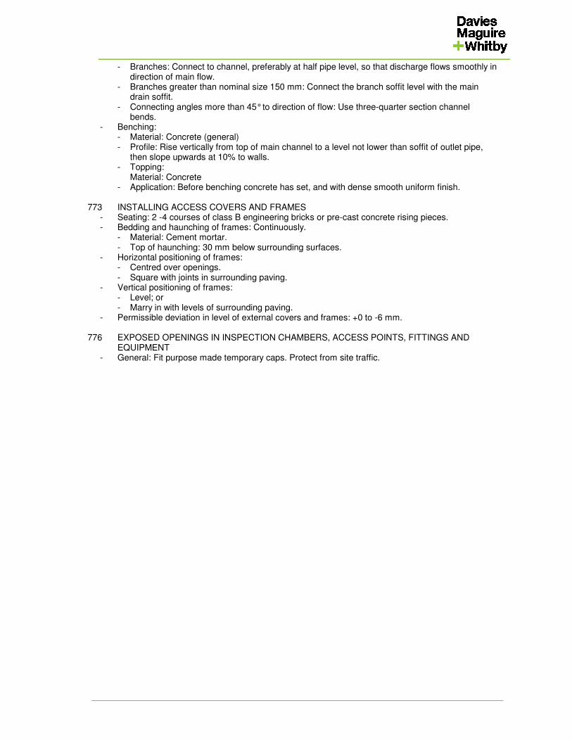
- Branches: Connect to channel, preferably at half pipe level, so that discharge flows smoothly in direction of main flow.
- Branches greater than nominal size 150 mm: Connect the branch soffit level with the main drain soffit.
- Connecting angles more than 45° to direction of flow: Use three-quarter section channel bends.
- Benching: - Material: Concrete (general) - Profile: Rise vertically from top of main channel to a level not lower than soffit of outlet pipe,
then slope upwards at 10% to walls. - Topping: Material: Concrete - Application: Before benching concrete has set, and with dense smooth uniform finish. 773 INSTALLING ACCESS COVERS AND FRAMES - Seating: 2 -4 courses of class B engineering bricks or pre-cast concrete rising pieces. - Bedding and haunching of frames: Continuously. - Material: Cement mortar. - Top of haunching: 30 mm below surrounding surfaces. - Horizontal positioning of frames: - Centred over openings. - Square with joints in surrounding paving. - Vertical positioning of frames: - Level; or - Marry in with levels of surrounding paving. - Permissible deviation in level of external covers and frames: +0 to -6 mm. 776 EXPOSED OPENINGS IN INSPECTION CHAMBERS, ACCESS POINTS, FITTINGS AND
EQUIPMENT - General: Fit purpose made temporary caps. Protect from site traffic.
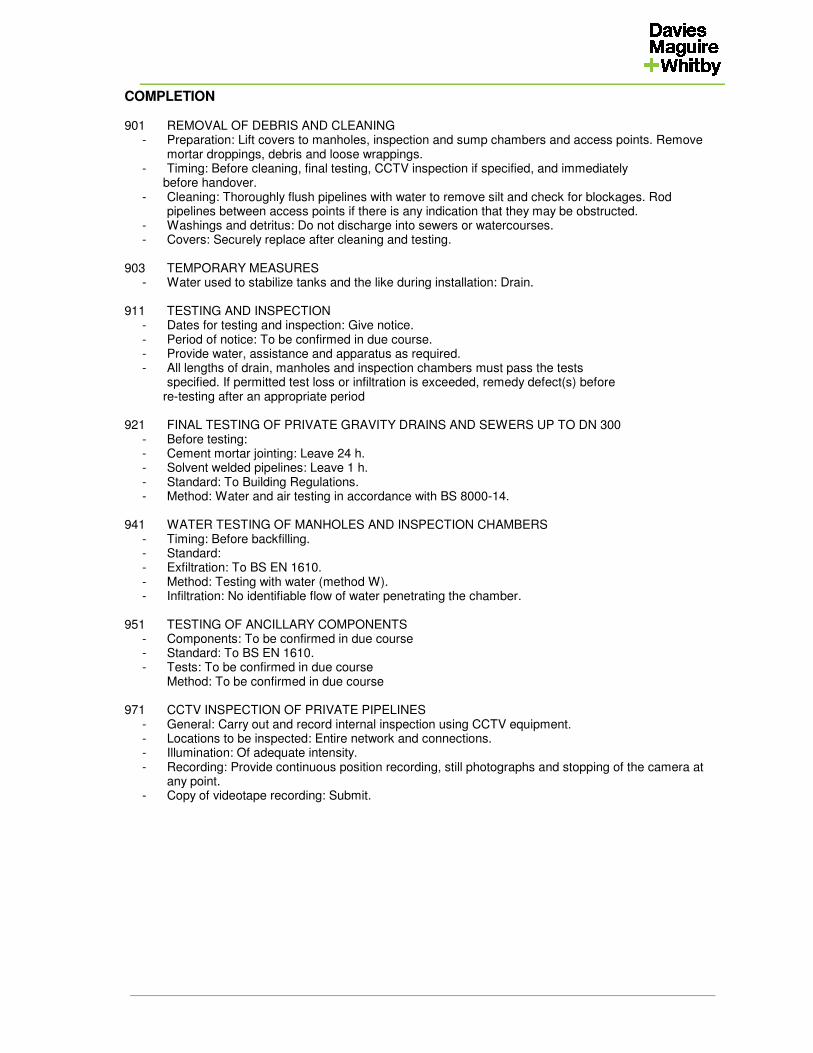
COMPLETION 901 REMOVAL OF DEBRIS AND CLEANING - Preparation: Lift covers to manholes, inspection and sump chambers and access points. Remove
mortar droppings, debris and loose wrappings. - Timing: Before cleaning, final testing, CCTV inspection if specified, and immediately before handover. - Cleaning: Thoroughly flush pipelines with water to remove silt and check for blockages. Rod
pipelines between access points if there is any indication that they may be obstructed. - Washings and detritus: Do not discharge into sewers or watercourses. - Covers: Securely replace after cleaning and testing. 903 TEMPORARY MEASURES - Water used to stabilize tanks and the like during installation: Drain. 911 TESTING AND INSPECTION - Dates for testing and inspection: Give notice. - Period of notice: To be confirmed in due course. - Provide water, assistance and apparatus as required. - All lengths of drain, manholes and inspection chambers must pass the tests specified. If permitted test loss or infiltration is exceeded, remedy defect(s) before re-testing after an appropriate period 921 FINAL TESTING OF PRIVATE GRAVITY DRAINS AND SEWERS UP TO DN 300 - Before testing: - Cement mortar jointing: Leave 24 h. - Solvent welded pipelines: Leave 1 h. - Standard: To Building Regulations. - Method: Water and air testing in accordance with BS 8000-14. 941 WATER TESTING OF MANHOLES AND INSPECTION CHAMBERS - Timing: Before backfilling. - Standard: - Exfiltration: To BS EN 1610. - Method: Testing with water (method W). - Infiltration: No identifiable flow of water penetrating the chamber. 951 TESTING OF ANCILLARY COMPONENTS - Components: To be confirmed in due course - Standard: To BS EN 1610. - Tests: To be confirmed in due course Method: To be confirmed in due course 971 CCTV INSPECTION OF PRIVATE PIPELINES - General: Carry out and record internal inspection using CCTV equipment. - Locations to be inspected: Entire network and connections. - Illumination: Of adequate intensity. - Recording: Provide continuous position recording, still photographs and stopping of the camera at
any point. - Copy of videotape recording: Submit.

978 LIFTING KEYS - Lifting keys: Supply suitable keys for each type of access cover. - Timing: At completion. 980 INSTRUCTIONS - Manufacturer’s user instructions: Refer to manufacture’s specifications and requirements

APPENDIX A
TEST RECORD SHEETS
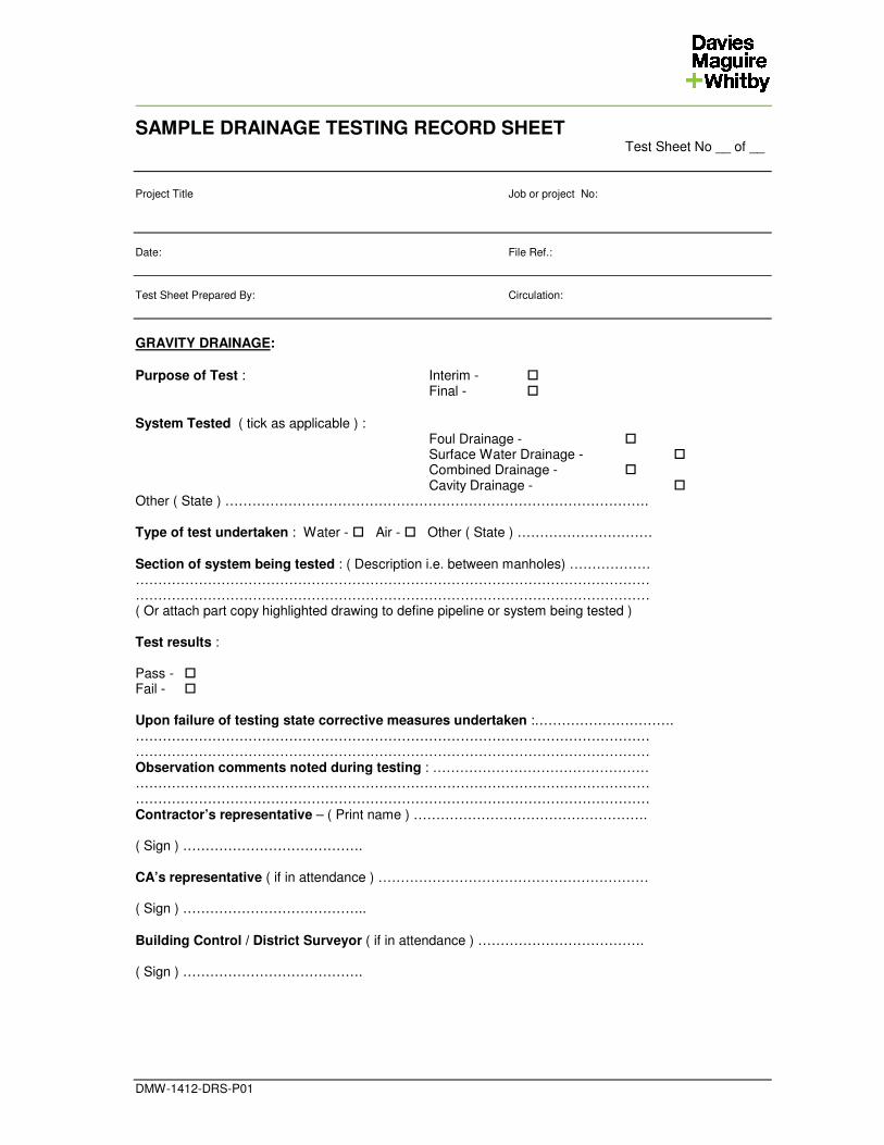
SAMPLE DRAINAGE TESTING RECORD SHEET Test Sheet No __ of __
Project Title Job or project No: Date: File Ref.: Test Sheet Prepared By: Circulation:
DMW-1412-DRS-P01
GRAVITY DRAINAGE: Purpose of Test : Interim - � Final - � System Tested ( tick as applicable ) :
Foul Drainage - � Surface Water Drainage - � Combined Drainage - � Cavity Drainage - �
Other ( State ) …………………………………………………………………………………. Type of test undertaken : Water - � Air - � Other ( State ) ………………………… Section of system being tested : ( Description i.e. between manholes) ……………… …………………………………………………………………………………………………… …………………………………………………………………………………………………… ( Or attach part copy highlighted drawing to define pipeline or system being tested ) Test results : Pass - � Fail - � Upon failure of testing state corrective measures undertaken :…………………………. …………………………………………………………………………………………………… …………………………………………………………………………………………………… Observation comments noted during testing : ………………………………………… …………………………………………………………………………………………………… …………………………………………………………………………………………………… Contractor’s representative – ( Print name ) ……………………………………………. ( Sign ) …………………………………. CA’s representative ( if in attendance ) …………………………………………………… ( Sign ) ………………………………….. Building Control / District Surveyor ( if in attendance ) ………………………………. ( Sign ) ………………………………….
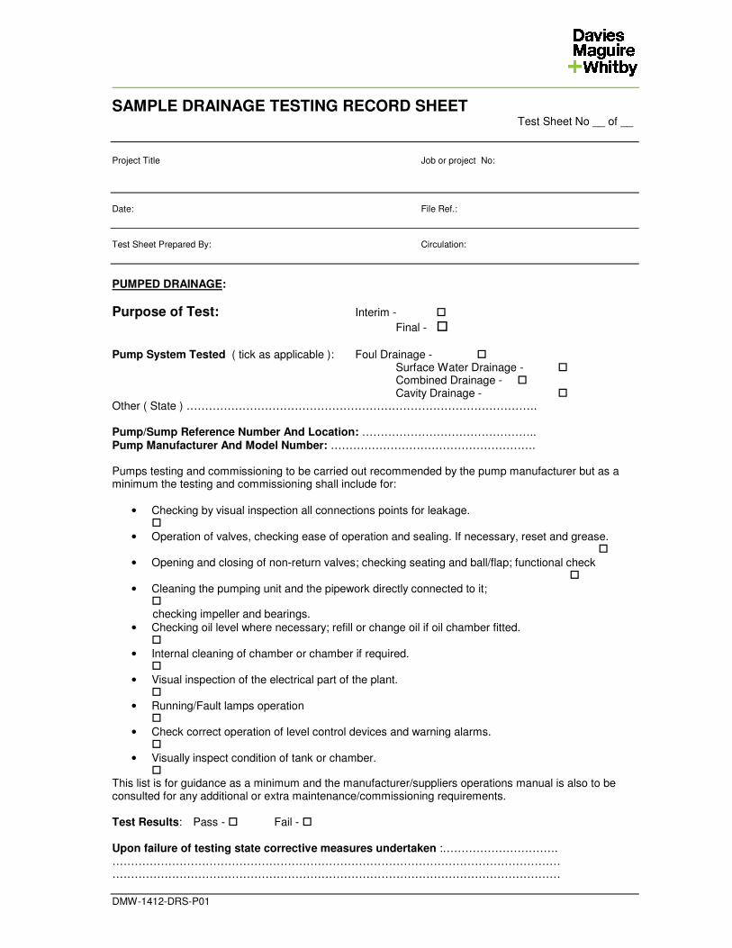
SAMPLE DRAINAGE TESTING RECORD SHEET Test Sheet No __ of __
Project Title Job or project No: Date: File Ref.: Test Sheet Prepared By: Circulation:
DMW-1412-DRS-P01
PUMPED DRAINAGE:
Purpose of Test: Interim - �
Final - � Pump System Tested ( tick as applicable ): Foul Drainage - �
Surface Water Drainage - � Combined Drainage - � Cavity Drainage - �
Other ( State ) …………………………………………………………………………………. Pump/Sump Reference Number And Location: ……………………………………….. Pump Manufacturer And Model Number: ………………………………………………. Pumps testing and commissioning to be carried out recommended by the pump manufacturer but as a minimum the testing and commissioning shall include for:
• Checking by visual inspection all connections points for leakage. �
• Operation of valves, checking ease of operation and sealing. If necessary, reset and grease. �
• Opening and closing of non-return valves; checking seating and ball/flap; functional check �
• Cleaning the pumping unit and the pipework directly connected to it; �
checking impeller and bearings.
• Checking oil level where necessary; refill or change oil if oil chamber fitted. �
• Internal cleaning of chamber or chamber if required. �
• Visual inspection of the electrical part of the plant. �
• Running/Fault lamps operation �
• Check correct operation of level control devices and warning alarms. �
• Visually inspect condition of tank or chamber. �
This list is for guidance as a minimum and the manufacturer/suppliers operations manual is also to be consulted for any additional or extra maintenance/commissioning requirements. Test Results: Pass - � Fail - � Upon failure of testing state corrective measures undertaken :…………………………. ………………………………………………………………………………………………………… …………………………………………………………………………………………………………
SAMPLE DRAINAGE TESTING RECORD SHEET Test Sheet No __ of __
Project Title Job or project No: Date: File Ref.: Test Sheet Prepared By: Circulation:
DMW-1412-DRS-P01
Observation comments noted during testing: ………………………………………………. ………………………………………………………………………………………………………… ………………………………………………………………………………………………………… Contractor’s Representative – ( Print name ) ……………………………( Sign )…………. CA’s Representative ( if in attendance ) …………………………………...( Sign ) ………...