the lil’ beaver operating manual - engrave-a-creteengraveacrete.com/media/docs/2013-beaver.pdf ·...
TRANSCRIPT

www.Engrave-A-Crete.com • Phone: 417-924-2300Order Hotline: 800-884-2114
Operating ManualThe Lil’ Beaver

2 1-417-924-2300
Copyright© Lil’ Beaver 2009/2010
byEngrave-A-Crete®, Inc.403 North Oak Mans� eld, MO 65704Phone: 1- 800-884-2114 or 1-417-924-2300Fax: 1-417-924-2500
This entire system is copyright © 2010. All rights reserved. No part of this manual or system shall be repro-duced, stored in a retrieval system, or transmitted by any means, electronic, mechanical, photocopying, record-ing, or by any information storage and retrieval system, or transmitted by email or otherwise, in any form or by any means without permission in writing from the author or from the publisher.
Although every precaution has been taken and all attempts have been made to verify information provided in this publication, neither the publisher nor the author assume responsibility for errors, inaccuracies, omissions or contrary interpretation of the subject matter herein. Neither is liability assumed for damages resulting from the use of the information contained herein.
This publication is not intended for use as a source of legal or accounting advice. The publisher wants to stress that the information contained herein may be subject to varying state and/or local laws or regulations. All users are advised to retain competent counsel to determine what state and/or local laws or regulations may apply to the user’s particular business.The purchaser or reader of this publication assumes responsibility for the use of these materials and information. Adherence to all applicable laws and regulations, both federal and state and local, governing professional licensing, business practices, advertising and all other aspects of doing business in the US, Canada or any other jurisdiction is the sole responsibility of the purchaser or reader. Neither the author nor the publisher assume any responsibility or liability whatsoever on the behalf of any purchaser or reader of these materials.
Engrave-A-Crete is a trademark registered in the U.S. Patent and Trademark Of� ce.
Machines and methods are patented under one or more of the following Patents #5,176,426 and #5,445,437 Other patents pending. Foreign registrations pending.
©2011 Engrave-A-Crete® / Lil’ Beaver™ 3
Table of ContentsGeneral Safety & Warnings ..........................................................................................................5
Operate Without Water ...............................................................................................................5Ground Fault Circuit Interrupter ...............................................................................................8
Lil’ Beaver Machine Parts .............................................................................................................9
Changing Wheels .........................................................................................................................11
Setting Depth Of Cut ...................................................................................................................12
Adjusting Pointers .......................................................................................................................14
Track Free Cutting .......................................................................................................................15Snapping Chalk Lines Single Handed ......................................................................................16Cutting Track Free Lines .........................................................................................................17Layout for Diagonal Tile ..........................................................................................................19Free Form Curves ...................................................................................................................20
Cutting Circles and Arcs .............................................................................................................21Setting Center Pivot in Place ...................................................................................................22
Circular Brick Patterns ...............................................................................................................24Tools Needed ............................................................................................................................25Terminology .............................................................................................................................26Setting the Center Pivot ...........................................................................................................27Attaching Circular Tracking ....................................................................................................28Cutting Long Lines ...................................................................................................................29
Adding Standard Connecting Bar Sections ...................................................................30Soldier Course Cutting .................................................................................................31
Cutting Short / Radial Cuts ......................................................................................................32Setting The Stroke Length For A 12” Soldier Course ...................................................32Rigid Pointer System .....................................................................................................33Cutting Soldier Course Bricks ......................................................................................34Setting the Stroke Length For Standard Brick Cuts .....................................................37
Overview of Standard Short / Radial Cuts .............................................................................39Circular Brick Cutting .............................................................................................................40
First Row Brick .............................................................................................................40Second Row Bricks ........................................................................................................43

4 1-417-924-2300
Table of Contents -ContinuedThird Row Bricks ..........................................................................................................44All Other Rows ..............................................................................................................45
Linear Brick .................................................................................................................................46Tools Needed ............................................................................................................................47Layout of Linear Brick Patterns ..............................................................................................48Cutting Long Lines ...................................................................................................................49Cutting Radial/Short Cuts ........................................................................................................51
First Brick Course .........................................................................................................52Second Brick Course .....................................................................................................52Third Brick Course ........................................................................................................53All Other Courses .........................................................................................................53
2nd Rail Mount Location ........................................................................................................54Last Rail Mount Location ........................................................................................................55
Touch Ups .....................................................................................................................................56Touching Up Under Cuts .........................................................................................................56Miscuts .....................................................................................................................................57
Blade Change ................................................................................................................................58
Tips, Tricks, & Troubleshooting .................................................................................................61

©2011 Engrave-A-Crete® / Lil’ Beaver™ 5
Operate Without Water
The diamond blades used with all Engrave-A-Crete Engravers are made to run dry.
All blades supplied by Engrave-A-Crete have segments that are laser welded to the core.
Some off brand blades may have soldered on segments and are very dangerous to use when cutting dry.
Cutting dry has many advantages and has little effect on blade life. Operate with a 5 to 6 1/2 hp shop vacuum as a dust collector.
General Safety & Warnings
Never use water with or near this or any other electrically powered
equipment.
Tip: Make operations easier by adding on extra sections of vacuum hose. 12 to 20 feet or more is really nice. Also, install a Gortex® Clean Stream � lter on the vacuum for better operation.
6 1-417-924-2300
1. Do not operate power tools in explosive atmo-spheres, such as in the presence of � ammable liquids, gases, or dust. Power tools create sparks which may ignite the dust or fumes.
2. Keep bystanders, children, and visitors away while operating a power tool. Distractions can cause you to lose control.
Electrical Safety3. Double insulated tools are equipped with a po-
larized plug (one blade is wider than the other.) This plug will � t in a polarized outlet only one way. If the plug does not � t fully in the outlet, reverse the plug. If it still does not � t, contact a quali� ed electrician to install a polarized outlet. Do not change the plug in any way. Double insulation eliminates the need for the three wire grounded power cord and grounded power sup-ply.
4. Avoid body contact with grounded surfaces such as pipes, radiators, ranges and refrigera-tors. There is an increased risk of electric shock if your body is grounded.
5. Do not expose power tools to rain or wet conditions. Water entering a power tool will increase the risk of electrical shock.
6. Do not abuse the cord. Never use the cord to carry the tools or pull the plug from an out let. Keep cord away from heat, oil, sharp edges or moving parts. Replace damaged cords immediately. Damaged cords increase the risk of electrical shock.
7. When operating a power tool outside, use an outdoor extension cord marked “W-A” or “W”. These cords are rated for outdoor use and re-duce the risk of electrical shock.
Personal Safety8. Stay alert, watch what you are doing and use
common sense when operating a power tool. Do not use tool while tired or under the in� u-ence of drugs, alcohol, or medication. A mo-ment of inattention while operating power tools may result in serious personal injury.
9. Dress properly. Do not wear loose clothing or jewelry. Contain long hair. Keep your hair, clothing, and gloves away from moving parts. Loose clothes, jewelry, or long hair can be caught in moving parts.
10. Avoid accidental starting. Be sure switch is off before plugging in. Carrying tools with your � nger on the switch or plugging in tools that have the switch on invites accidents.
11.Remove adjusting keys or wrenches before turning the tool on. A wrench or a key that is left attached to a rotating part of the tool may result in personal injury.
12.Do not overreach. Keep proper footing and balance at all times. Proper footing and balance enables better control of the tool in unexpected situations.
13.Use safety equipment. Always wear eye pro-tection. Dust mask, non-skid safety shoes, hard hat, and hearing protection must be used for appropriate conditions. Ordinary eye or sun glasses are NOT eye protection.
14.Do not force tool. Use the correct tool for your application. The correct tool will do the job bet-ter and safer at the rate for which it is designed.
General Safety Rules Warning: Read & Understand All Instructions.
©2011 Engrave-A-Crete® / Lil’ Beaver™ 7
15.Disconnect the plug from the power source before making any adjustments, changing ac-cessories, or storing the tool. Such preventive safety measures reduce the risk of starting the tool accidentally.
16.Store idle tools out of reach of children and other untrained persons. Tools are dangerous in the hands of untrained users.
17.Check for misalignment or binding of moving parts, breakage of parts, and any other con-dition that may affect the tools operation. If damaged, have the tool serviced before using. Many accidents are caused by poorly main-tained tools.
18.Use only accessories that are recommended by the manufacturer for your model. Accessories that may be suitable for one tool, may become hazardous when used on another tool.
19.Tool service must be performed only by quali-� ed repair personnel. Service maintenance per-formed by unquali� ed personnel could result in a risk of injury.
20.When servicing a tool, use only identical re-placement parts. Use of unauthorized parts or failure to follow maintenance instructions may createa risk of electric shock or injury.
Speci� c Safety Rules
1. DANGER! Keep hands away from cutting area and blade. Keep your second hand on auxil-iary handle, or motor housing. If both hands are holding the saw, they cannot be cut by the blade.
2. Always use blades with correct size and shape arbor holes. Blades that do not match the mounting hardware of the saw will run eccen-trically, causing loss of control.
3. Never use damaged or incorrect blade wash-ers or bolts. The blade washers and bolt were specially designed for your saw, for optimu per-formance and safety of operation.
4. Maintain a � rm grip with both hands on the saw and position your body and arm to allow you to resist KICKBACK forces.
5. When operating the saw, keep the cord away from the cutting area and position it so that it will not be caught on the work-piece during the cutting operation. The tool is provided with a front grip and rear handle for two hand opera-tion. Operate with proper hand support and supply cord routing away from the work area.
WARNING: Blade coasts to stop after switch is released. Contact with a coasting blade can cause serious injury.
6. Some material contains chemicals which may be toxic. Take caution to prevent working dust inhalation and skin contact. Follow material supplier safety data.
SAVE THESE INSTRUCTIONS
WARNING: MISUSE or failure to follow the safety rules stated in this instruction manual may cause
serious personal injury.
8 1-417-924-2300
WARNING
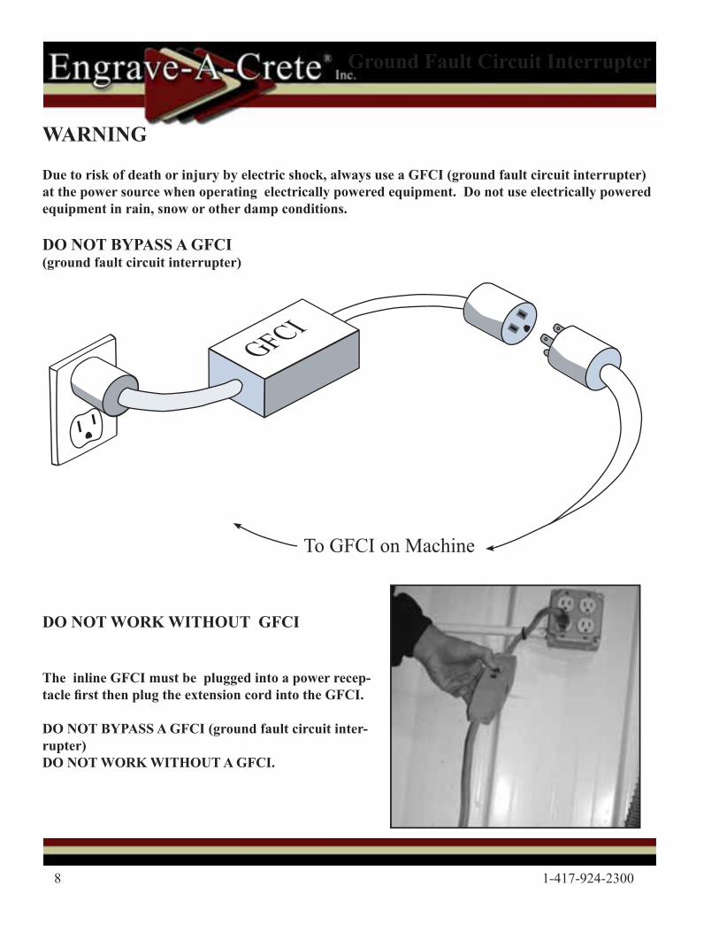
Due to risk of death or injury by electric shock, always use a GFCI (ground fault circuit interrupter) at the power source when operating electrically powered equipment. Do not use electrically powered equipment in rain, snow or other damp conditions.
DO NOT BYPASS A GFCI (ground fault circuit interrupter)
Ground Fault Circuit Interrupter
DO NOT WORK WITHOUT GFCI
The inline GFCI must be plugged into a power recep-tacle � rst then plug the extension cord into the GFCI.
DO NOT BYPASS A GFCI (ground fault circuit inter-rupter) DO NOT WORK WITHOUT A GFCI.
GFCI
To GFCI on Machine
©2011 Engrave-A-Crete® / Lil’ Beaver™ 9
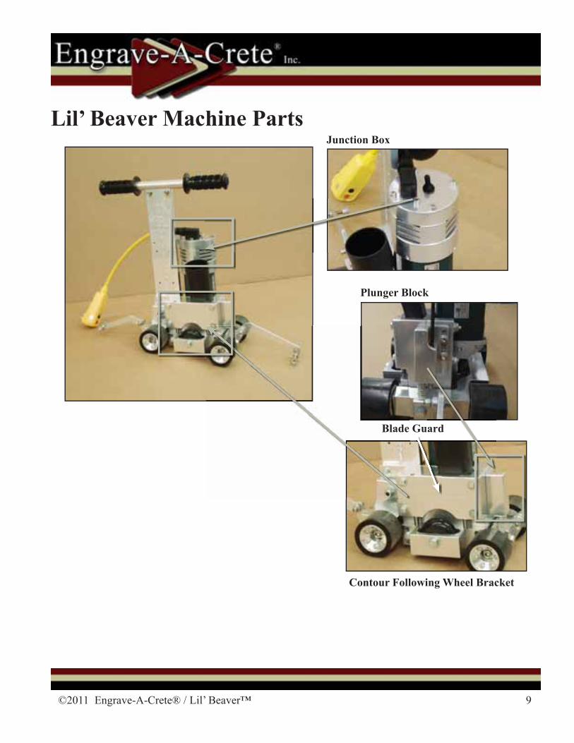
Lil’ Beaver Machine Parts
Blade Guard
Contour Following Wheel Bracket
Blade
Plunger Block
Junction Box
ard
10 1-417-924-2300
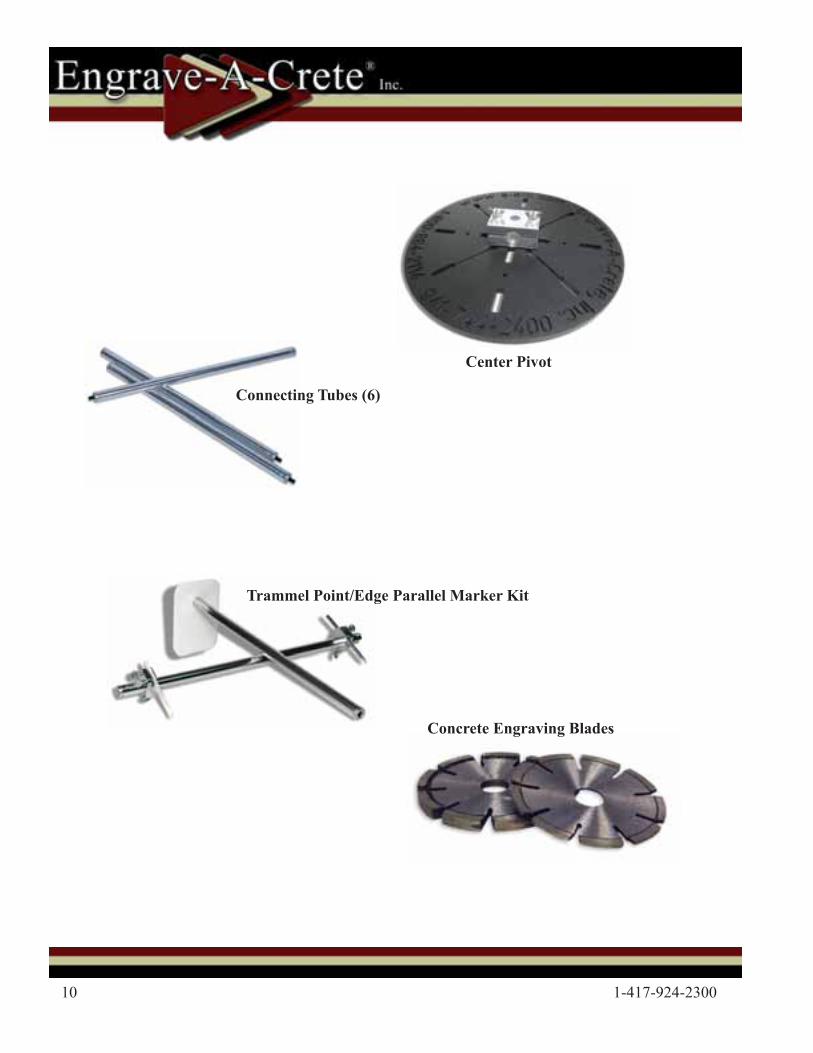
Center Pivot
Connecting Tubes (6)
Trammel Point/Edge Parallel Marker Kit
Concrete Engraving Blades
©2011 Engrave-A-Crete® / Lil’ Beaver™ 11
Track free cutting done prior to other engraving will insure smoother Free-Of-The-Track operations.
(The wheels won’t be bouncing over or side tracked by other grooves.)
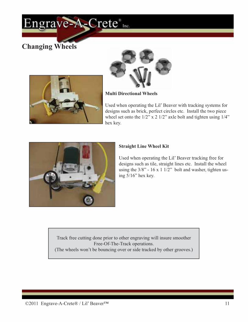
Multi Directional Wheels
Used when operating the Lil’ Beaver with tracking systems for designs such as brick, perfect circles etc. Install the two piece wheel set onto the 1/2” x 2 1/2” axle bolt and tighten using 1/4” hex key.
Straight Line Wheel Kit
Used when operating the Lil’ Beaver tracking free for designs such as tile, straight lines etc. Install the wheel using the 3/8” - 16 x 1 1/2” bolt and washer, tighten us-ing 5/16” hex key.
Changing Wheels
12 1-417-924-2300
Note: Check/adjust the depth of cut when the engraver � rst arrives, as the blade wears, and when a new blade is installed.
Setting Depth Of Cut
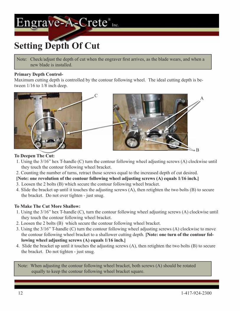
Primary Depth Control-Maximum cutting depth is controlled by the contour following wheel. The ideal cutting depth is be-tween 1/16 to 1/8 inch deep.
To Deepen The Cut:1. Using the 3/16” hex T-handle (C) turn the contour following wheel adjusting screws (A) clockwise until
they touch the contour following wheel bracket. 2. Counting the number of turns, retract those screws equal to the increased depth of cut desired. [Note: one revolution of the contour following wheel adjusting screws (A) equals 1/16 inch.]3. Loosen the 2 bolts (B) which secure the contour following wheel bracket.4. Slide the bracket up until it touches the adjusting screws (A), then retighten the two bolts (B) to secure
the bracket. Do not over tighten - just snug.
To Make The Cut More Shallow:1. Using the 3/16” hex T-handle (C), turn the contour following wheel adjusting screws (A) clockwise until
they touch the contour following wheel bracket. 2. Loosen the 2 bolts (B) which secure the contour following wheel bracket.3. Using the 3/16” T-handle (C) turn the contour following wheel adjusting screws (A) clockwise to move
the contour following wheel bracket to a shallower cutting depth. [Note: one turn of the contour fol-lowing wheel adjusting screws (A) equals 1/16 inch.]
4. Slide the bracket up until it touches the adjusting screws (A), then retighten the two bolts (B) to secure the bracket. Do not tighten - just snug.
Note: When adjusting the contour following wheel bracket, both screws (A) should be rotated equally to keep the contour following wheel bracket square.
A
B
C
©2011 Engrave-A-Crete® / Lil’ Beaver™ 13
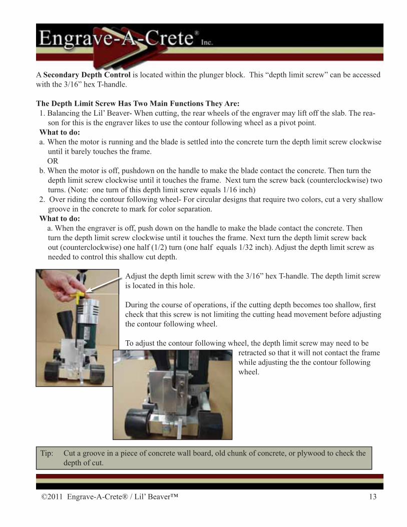
A Secondary Depth Control is located within the plunger block. This “depth limit screw” can be accessed with the 3/16” hex T-handle.
The Depth Limit Screw Has Two Main Functions They Are:1. Balancing the Lil’ Beaver- When cutting, the rear wheels of the engraver may lift off the slab. The rea-
son for this is the engraver likes to use the contour following wheel as a pivot point.What to do:a. When the motor is running and the blade is settled into the concrete turn the depth limit screw clockwise
until it barely touches the frame. ORb. When the motor is off, pushdown on the handle to make the blade contact the concrete. Then turn the
depth limit screw clockwise until it touches the frame. Next turn the screw back (counterclockwise) two turns. (Note: one turn of this depth limit screw equals 1/16 inch)
2. Over riding the contour following wheel- For circular designs that require two colors, cut a very shallow groove in the concrete to mark for color separation.
What to do: a. When the engraver is off, push down on the handle to make the blade contact the concrete. Then
turn the depth limit screw clockwise until it touches the frame. Next turn the depth limit screw back out (counterclockwise) one half (1/2) turn (one half equals 1/32 inch). Adjust the depth limit screw as needed to control this shallow cut depth.
Adjust the depth limit screw with the 3/16” hex T-handle. The depth limit screw is located in this hole.
During the course of operations, if the cutting depth becomes too shallow, � rst check that this screw is not limiting the cutting head movement before adjusting the contour following wheel.
To adjust the contour following wheel, the depth limit screw may need to be retracted so that it will not contact the frame while adjusting the the contour following wheel.
Tip: Cut a groove in a piece of concrete wall board, old chunk of concrete, or plywood to check the depth of cut.
14 1-417-924-2300
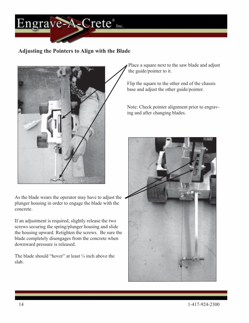
Adjusting the Pointers to Align with the Blade
Place a square next to the saw blade and adjust the guide/pointer to it.
Flip the square to the other end of the chassis base and adjust the other guide/pointer.
Note: Check pointer alignment prior to engrav-ing and after changing blades.
As the blade wears the operator may have to adjust the plunger housing in order to engage the blade with the concrete.
If an adjustment is required, slightly release the two screws securing the spring/plunger housing and slide the housing upward. Retighten the screws. Be sure the blade completely disengages from the concrete when downward pressure is released.
The blade should “hover” at least ¼ inch above the slab.
©2011 Engrave-A-Crete® / Lil’ Beaver™ 15
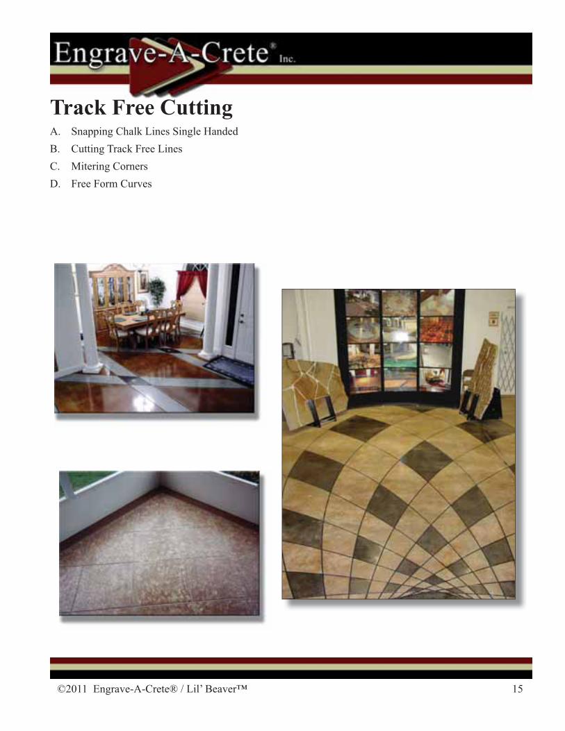
Track Free CuttingA. Snapping Chalk Lines Single HandedB. Cutting Track Free LinesC. Mitering CornersD. Free Form Curves
16 1-417-924-2300
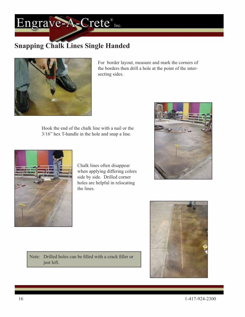
Note: Drilled holes can be � lled with a crack � ller or just left.
Snapping Chalk Lines Single Handed
For border layout, measure and mark the corners of the borders then drill a hole at the point of the inter-secting sides.
Hook the end of the chalk line with a nail or the 3/16” hex T-handle in the hole and snap a line.
Chalk lines often disappear when applying differing colors side by side. Drilled corner holes are helpful in relocating the lines.
©2011 Engrave-A-Crete® / Lil’ Beaver™ 17
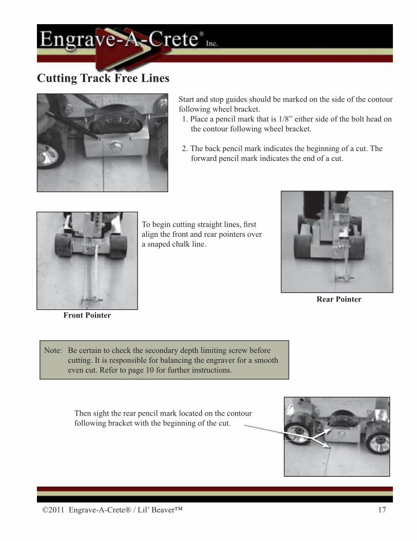
Note: Be certain to check the secondary depth limiting screw before cutting. It is responsible for balancing the engraver for a smooth even cut. Refer to page 10 for further instructions.
Start and stop guides should be marked on the side of the contour following wheel bracket.1. Place a pencil mark that is 1/8” either side of the bolt head on
the contour following wheel bracket.
2. The back pencil mark indicates the beginning of a cut. The forward pencil mark indicates the end of a cut.
Then sight the rear pencil mark located on the contour following bracket with the beginning of the cut.
Cutting Track Free Lines
To begin cutting straight lines, � rst align the front and rear pointers over a snaped chalk line.
Front Pointer Rear Pointer
Rear Pointer
18 1-417-924-2300
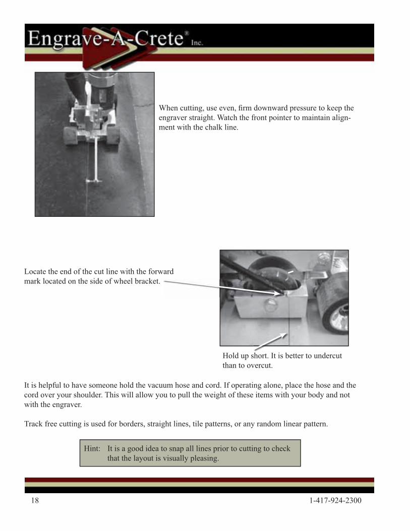
When cutting, use even, � rm downward pressure to keep the engraver straight. Watch the front pointer to maintain align-ment with the chalk line.
Locate the end of the cut line with the forward mark located on the side of wheel bracket.
It is helpful to have someone hold the vacuum hose and cord. If operating alone, place the hose and the cord over your shoulder. This will allow you to pull the weight of these items with your body and not with the engraver.
Track free cutting is used for borders, straight lines, tile patterns, or any random linear pattern.
Hint: It is a good idea to snap all lines prior to cutting to check that the layout is visually pleasing.
Hold up short. It is better to undercut than to overcut.
©2011 Engrave-A-Crete® / Lil’ Beaver™ 19
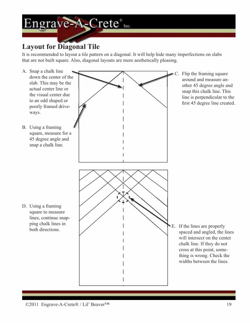
Layout for Diagonal TileIt is recommended to layout a tile pattern on a diagonal. It will help hide many imperfections on slabs that are not built square. Also, diagonal layouts are more aesthetically pleasing.
A. Snap a chalk line down the center of the slab. This may be the actual center line or the visual center due to an odd shaped or poorly framed drive-ways.
B. Using a framing square, measure for a 45 degree angle and snap a chalk line.
C. Flip the framing square around and measure an-other 45 degree angle and snap this chalk line. This line is perpendicular to the � rst 45 degree line created.
D. Using a framing square to measure lines, continue snap-ping chalk lines in both directions.
E. If the lines are properly spaced and angled, the lines will intersect on the center chalk line. If they do not cross at this point, some-thing is wrong. Check the widths between the lines.
20 1-417-924-2300
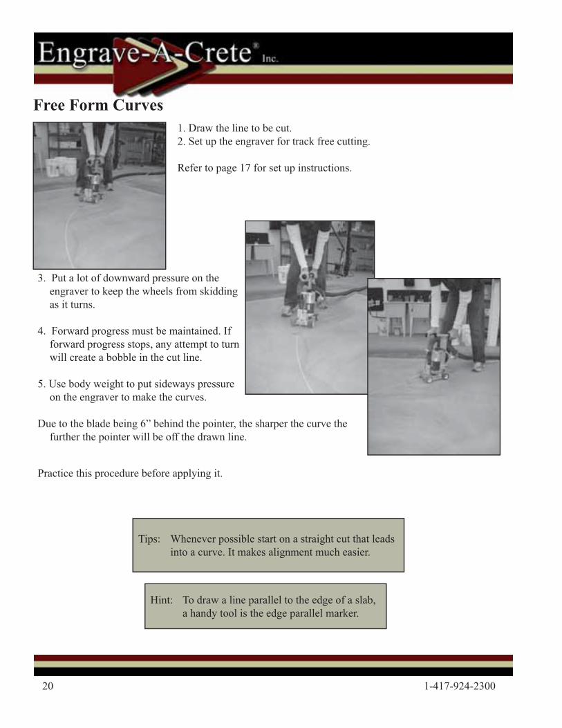
Free Form Curves 1. Draw the line to be cut.2. Set up the engraver for track free cutting.
Refer to page 17 for set up instructions.
Hint: To draw a line parallel to the edge of a slab, a handy tool is the edge parallel marker.
3. Put a lot of downward pressure on the engraver to keep the wheels from skidding as it turns.
4. Forward progress must be maintained. If forward progress stops, any attempt to turn will create a bobble in the cut line.
5. Use body weight to put sideways pressure on the engraver to make the curves.
Due to the blade being 6” behind the pointer, the sharper the curve the further the pointer will be off the drawn line.
Tips: Whenever possible start on a straight cut that leads into a curve. It makes alignment much easier.
Practice this procedure before applying it.
©2011 Engrave-A-Crete® / Lil’ Beaver™ 21
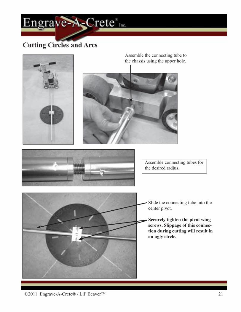
Assemble the connecting tube to the chassis using the upper hole.
Slide the connecting tube into the center pivot.
Securely tighten the pivot wing screws. Slippage of this connec-tion during cutting will result in an ugly circle.
Cutting Circles and Arcs
Assemble connecting tubes for the desired radius.
22 1-417-924-2300
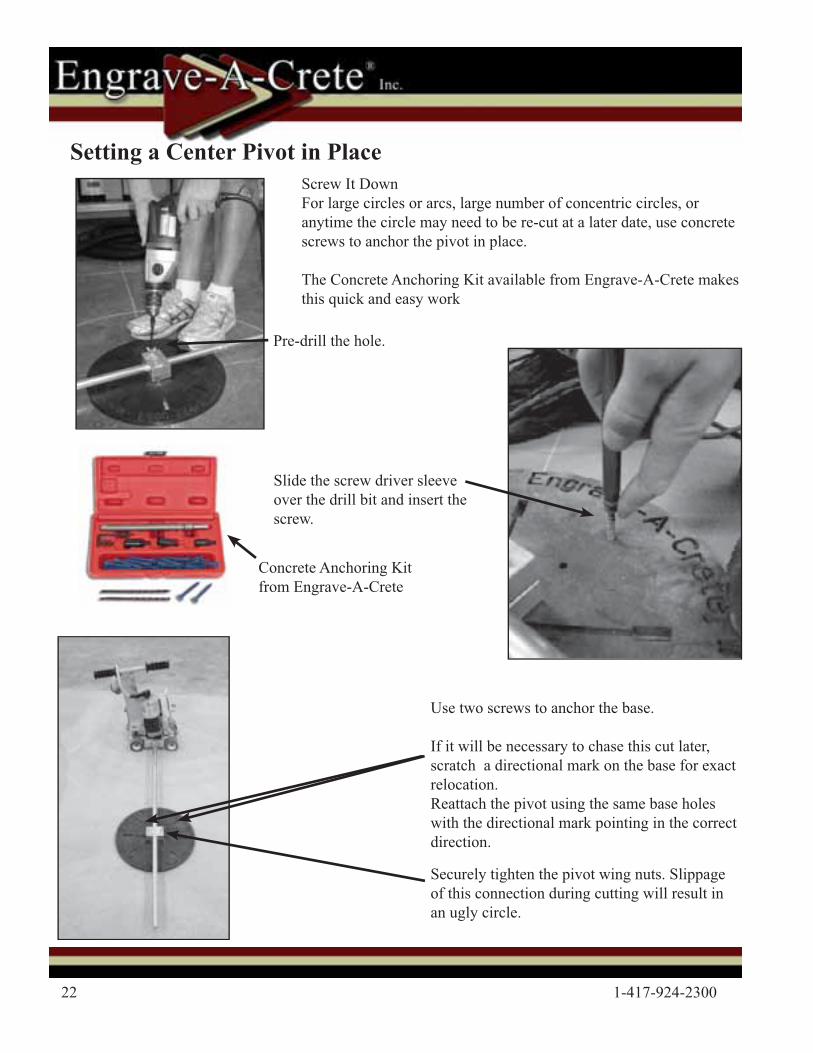
Screw It DownFor large circles or arcs, large number of concentric circles, or anytime the circle may need to be re-cut at a later date, use concrete screws to anchor the pivot in place.
The Concrete Anchoring Kit available from Engrave-A-Crete makes this quick and easy work
Pre-drill the hole.
Slide the screw driver sleeve over the drill bit and insert the screw.
Use two screws to anchor the base.
If it will be necessary to chase this cut later, scratch a directional mark on the base for exact relocation. Reattach the pivot using the same base holes with the directional mark pointing in the correct direction.
Securely tighten the pivot wing nuts. Slippage of this connection during cutting will result in an ugly circle.
Concrete Anchoring Kit from Engrave-A-Crete
Setting a Center Pivot in Place
©2011 Engrave-A-Crete® / Lil’ Beaver™ 23
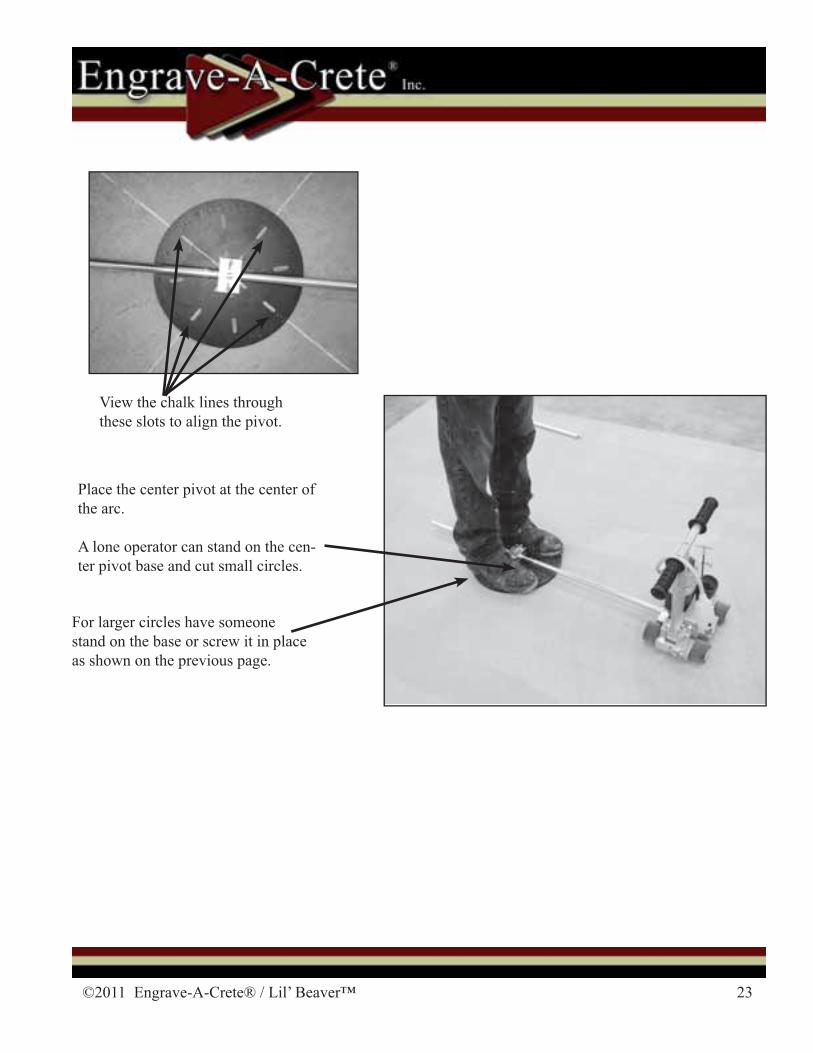
Place the center pivot at the center of the arc.
A lone operator can stand on the cen-ter pivot base and cut small circles.
For larger circles have someone stand on the base or screw it in place as shown on the previous page.
View the chalk lines through these slots to align the pivot.
24 1-417-924-2300
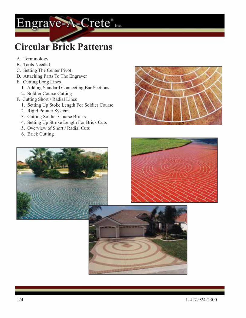
Circular Brick PatternsA. TerminologyB. Tools NeededC. Setting The Center PivotD. Attaching Parts To The EngraverE. Cutting Long Lines 1. Adding Standard Connecting Bar Sections 2. Soldier Course CuttingF. Cutting Short / Radial Lines 1. Setting Up Stoke Length For Soldier Course 2. Rigid Pointer System 3. Cutting Soldier Course Bricks 4. Setting Up Stroke Length For Brick Cuts 5. Overview of Short / Radial Cuts 6. Brick Cutting

©2011 Engrave-A-Crete® / Lil’ Beaver™ 25
Tools Needed- additional purchace requiredTools needed to begin circular pattern
Hammer Drill
Lil’ Beaver
Center Pivot
Connecting BarConnecting Bar Stabilizer
Primary Connecting Bar
Concrete Anchoring Kit
26 1-417-924-2300
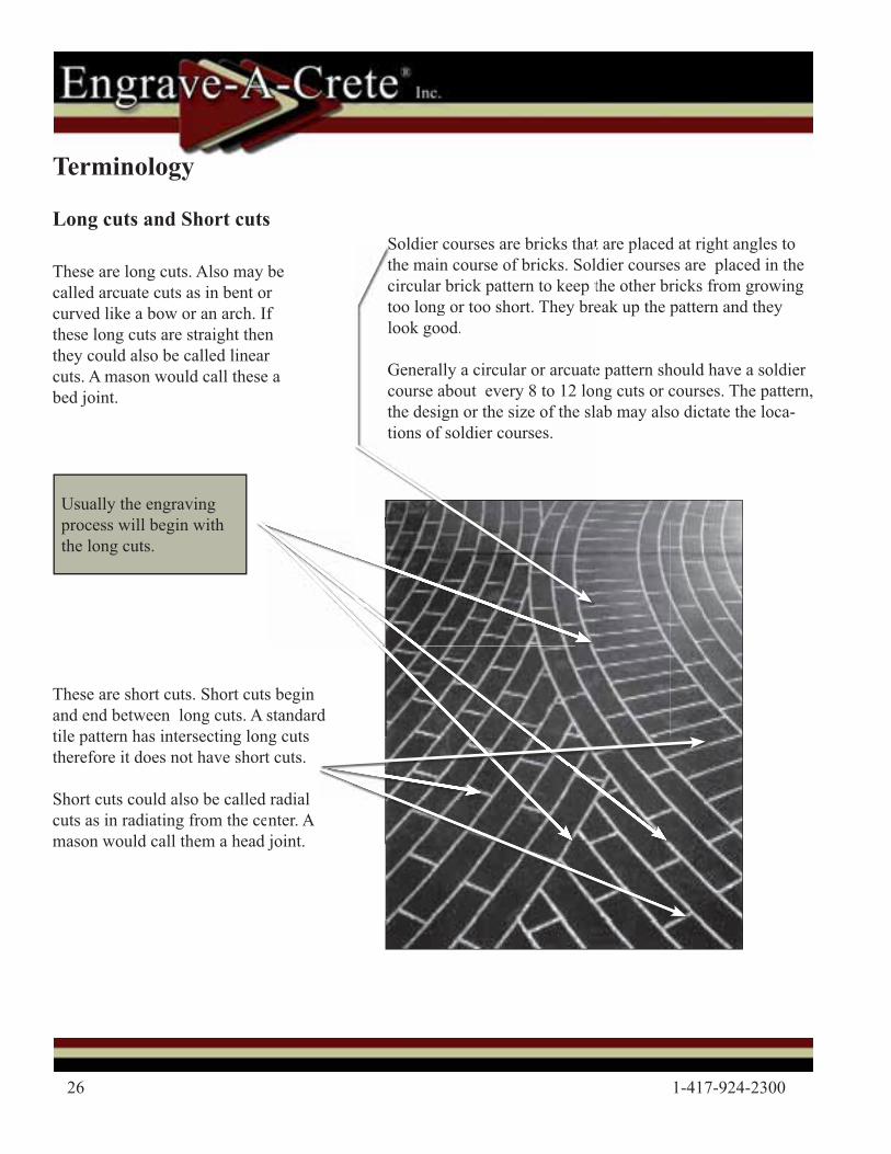
Usually the engraving process will begin with the long cuts.
These are short cuts. Short cuts begin and end between long cuts. A standard tile pattern has intersecting long cuts therefore it does not have short cuts.
Short cuts could also be called radial cuts as in radiating from the center. A mason would call them a head joint.
utsA sonort
d ced joint
s beginstandard
ng cutst cuts.
radial enter. A
joint
Terminology
Long cuts and Short cutsSoldier courses are bricks that are placed at right angles to the main course of bricks. Soldier courses are placed in the circular brick pattern to keep the other bricks from growing too long or too short. They break up the pattern and they look good.
Generally a circular or arcuate pattern should have a soldier course about every 8 to 12 long cuts or courses. The pattern, the design or the size of the slab may also dictate the loca-tions of soldier courses.
Soldier courses are bricks thatthe main course of bricks. Solcircular brick pattern to keep ttoo long or too short. They brelook good.
Generally a circular or arcuatecourse about every 8 to 12 lonthe design or the size of the sltions of soldier courses.
These are long cuts. Also may be called arcuate cuts as in bent or curved like a bow or an arch. If these long cuts are straight then they could also be called linear cuts. A mason would call these a bed joint.
©2011 Engrave-A-Crete® / Lil’ Beaver™ 27
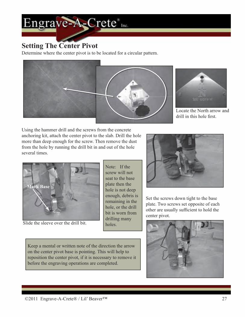
Setting The Center PivotDetermine where the center pivot is to be located for a circular pattern.
Using the hammer drill and the screws from the concrete anchoring kit, attach the center pivot to the slab. Drill the hole more than deep enough for the screw. Then remove the dust from the hole by running the drill bit in and out of the hole several times.
Locate the North arrow and drill in this hole � rst.
Set the screws down tight to the base plate. Two screws set opposite of each other are usually suf� cient to hold the center pivot.
Slide the sleeve over the drill bit.
Mark Base
Keep a mental or written note of the direction the arrow on the center pivot base is pointing. This will help to reposition the center pivot, if it is necessary to remove it before the engraving operations are completed.
Note: If the screw will not seat to the base plate then the hole is not deep enough, debris is remaining in the hole, or the drill bit is worn from drilling many holes.
28 1-417-924-2300
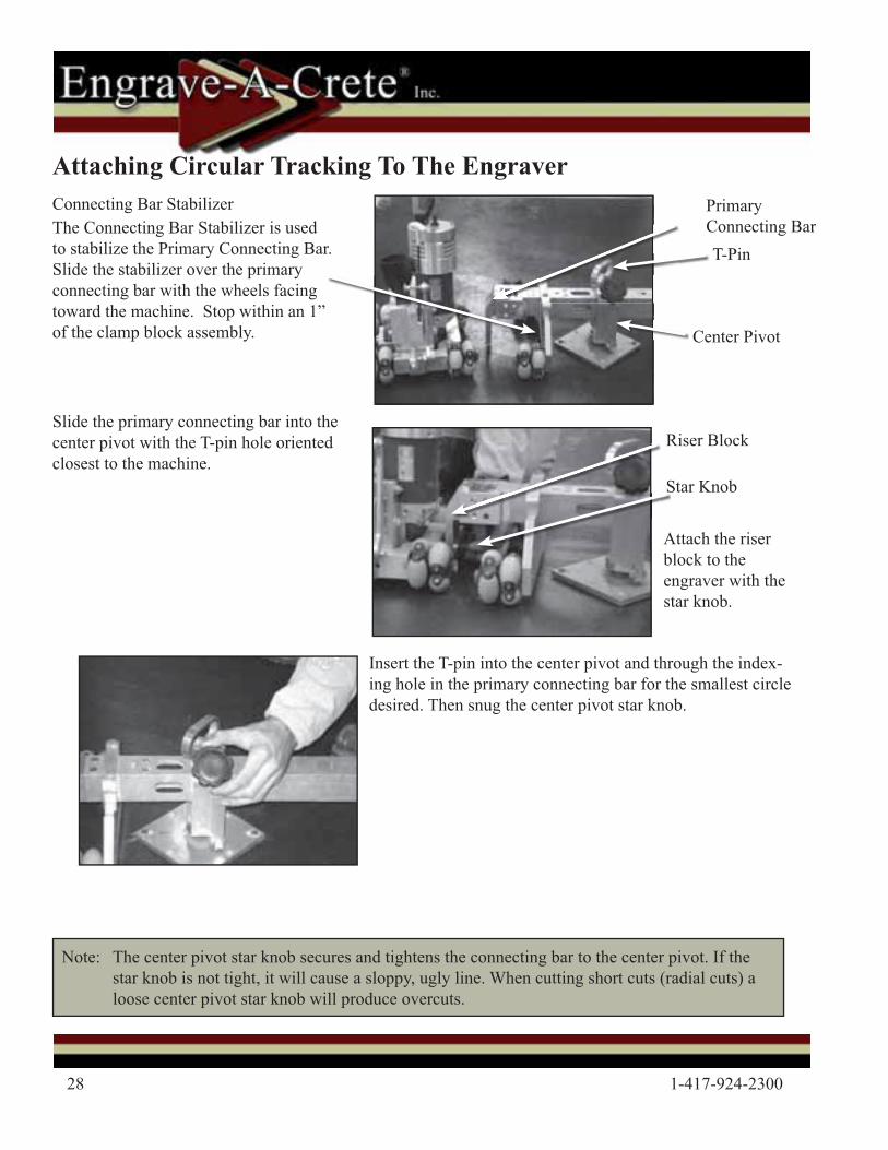
Primary Connecting Bar
Connecting Bar Stabilizer
Star Knob
Riser Block
Center Pivot
Slide the primary connecting bar into the center pivot with the T-pin hole oriented closest to the machine.
Attach the riser block to the engraver with the star knob.
Insert the T-pin into the center pivot and through the index-ing hole in the primary connecting bar for the smallest circle desired. Then snug the center pivot star knob.
Note: The center pivot star knob secures and tightens the connecting bar to the center pivot. If the star knob is not tight, it will cause a sloppy, ugly line. When cutting short cuts (radial cuts) a loose center pivot star knob will produce overcuts.
T-Pin
Attaching Circular Tracking To The Engraver
The Connecting Bar Stabilizer is used to stabilize the Primary Connecting Bar. Slide the stabilizer over the primary connecting bar with the wheels facing toward the machine. Stop within an 1” of the clamp block assembly.
©2011 Engrave-A-Crete® / Lil’ Beaver™ 29
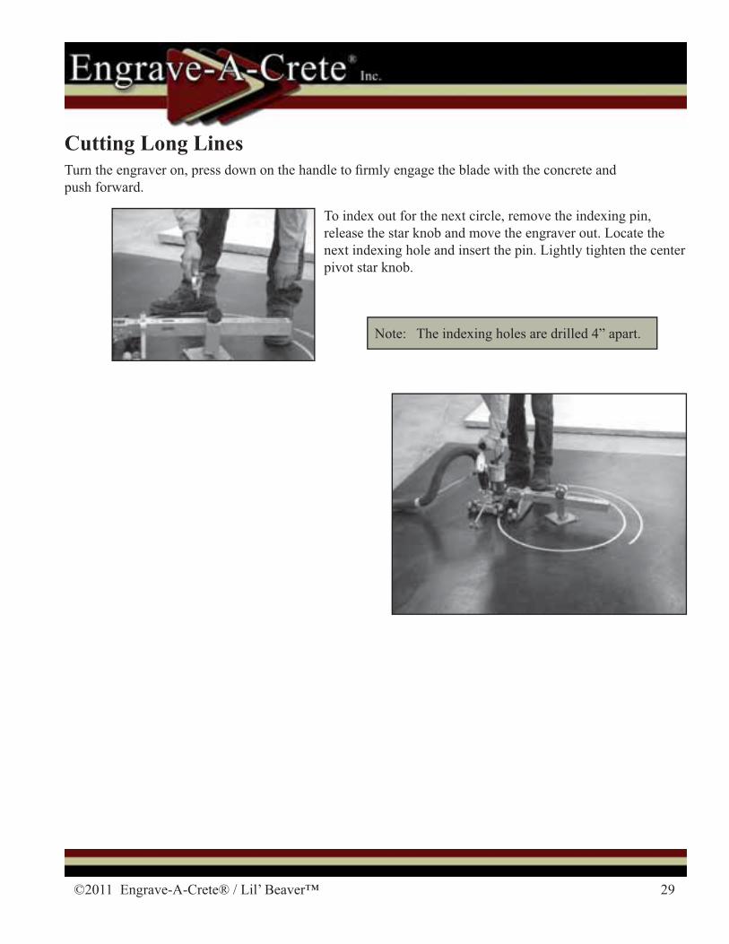
To index out for the next circle, remove the indexing pin, release the star knob and move the engraver out. Locate the next indexing hole and insert the pin. Lightly tighten the center pivot star knob.
Cutting Long LinesTurn the engraver on, press down on the handle to � rmly engage the blade with the concrete and push forward.
Note: The indexing holes are drilled 4” apart.
30 1-417-924-2300
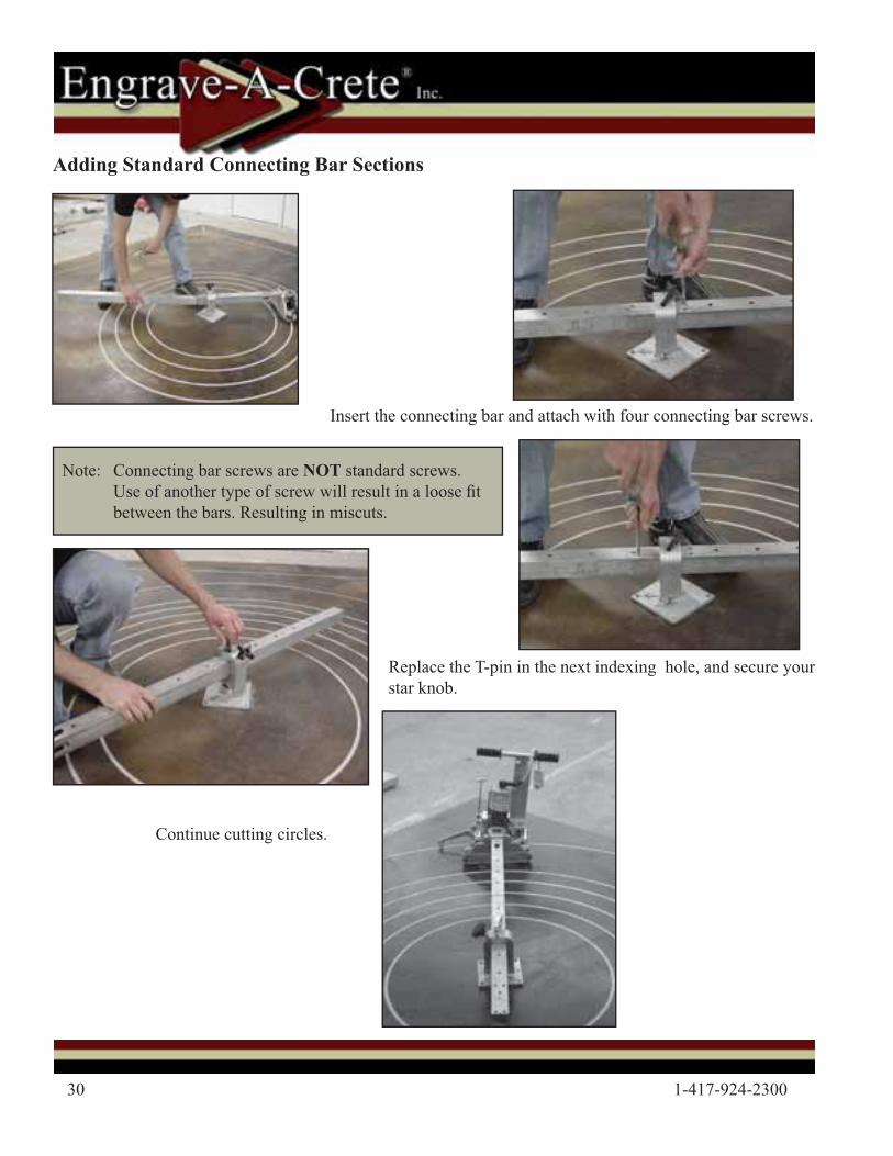
Note: Connecting bar screws are NOT standard screws. Use of another type of screw will result in a loose � t between the bars. Resulting in miscuts.
Insert the connecting bar and attach with four connecting bar screws.
Replace the T-pin in the next indexing hole, and secure your star knob.
Continue cutting circles.
Adding Standard Connecting Bar Sections

©2011 Engrave-A-Crete® / Lil’ Beaver™ 31
Soldier Course Cutting
For a 12” long brick, index out 3 holes.
Insert the T-pin and tighten the star knob.
Visually check that the engraver is correctly located for the next cut. Then cut the circle.
Soldier Courses are used in circular brick patterns to control the over all maximum brick length.
Typically when you are close to the center pivot you will put in a soldier course after six (6) to eight (8) rows. As you get fur-ther away from the center pivot a soldier course can be added after every eight (8) to twelve (12) brick rows.
32 1-417-924-2300
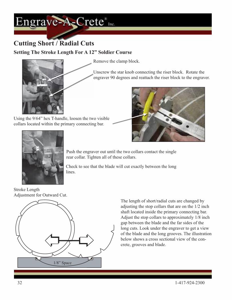
Remove the clamp block.
Unscrew the star knob connecting the riser block. Rotate the engraver 90 degrees and reattach the riser block to the engraver.
Cutting Short / Radial Cuts
Check to see that the blade will cut exactly between the long lines.
Push the engraver out until the two collars contact the single rear collar. Tighten all of these collars.
Using the 9/64” hex T-handle, loosen the two visible collars located within the primary connecting bar.
The length of short/radial cuts are changed by adjusting the stop collars that are on the 1/2 inch shaft located inside the primary connecting bar. Adjust the stop collars to approximately 1/8 inch gap between the blade and the far sides of the long cuts. Look under the engraver to get a view of the blade and the long grooves. The illustration below shows a cross sectional view of the con-crete, grooves and blade.
Stroke Length Adjustment for Outward Cut.
Setting The Stroke Length For A 12” Soldier Course
1/8” Space
©2011 Engrave-A-Crete® / Lil’ Beaver™ 33
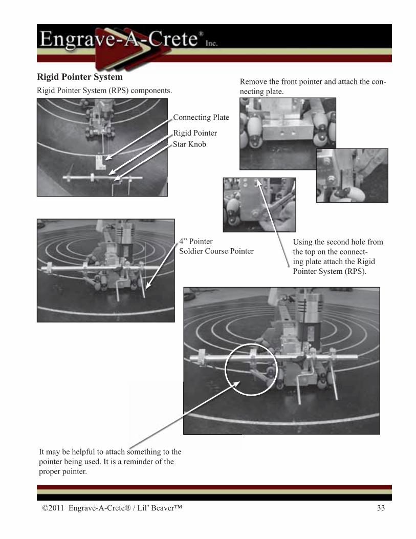
Rigid Pointer System (RPS) components.
Using the second hole from the top on the connect-ing plate attach the Rigid Pointer System (RPS).
It may be helpful to attach something to the pointer being used. It is a reminder of the proper pointer.
Remove the front pointer and attach the con-necting plate.
Rigid Pointer System
Rigid PointerStar KnobRS
4” PointerSoldier Course Pointer
thi t th
Connecting Plate
34 1-417-924-2300
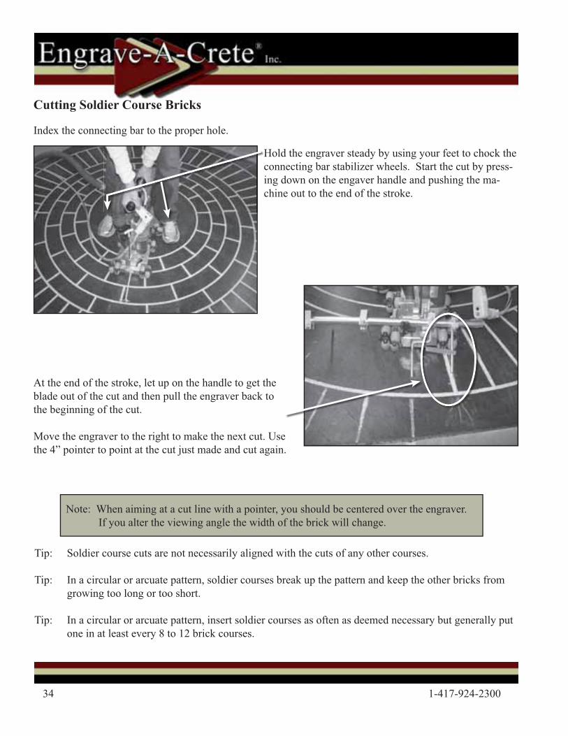
Hold the engraver steady by using your feet to chock the connecting bar stabilizer wheels. Start the cut by press-ing down on the engaver handle and pushing the ma-chine out to the end of the stroke.
At the end of the stroke, let up on the handle to get the blade out of the cut and then pull the engraver back to the beginning of the cut.
Move the engraver to the right to make the next cut. Use the 4” pointer to point at the cut just made and cut again.
Index the connecting bar to the proper hole.
Note: When aiming at a cut line with a pointer, you should be centered over the engraver. If you alter the viewing angle the width of the brick will change.
Cutting Soldier Course Bricks
Tip: Soldier course cuts are not necessarily aligned with the cuts of any other courses.
Tip: In a circular or arcuate pattern, soldier courses break up the pattern and keep the other bricks from growing too long or too short.
Tip: In a circular or arcuate pattern, insert soldier courses as often as deemed necessary but generally put one in at least every 8 to 12 brick courses.

©2011 Engrave-A-Crete® / Lil’ Beaver™ 35
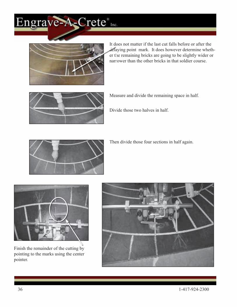
To be sure there is not a small sliver of a brick remaining with the last cut, determine a delaying point to make it appear that the bricks perfectly � t into place.
1. Make a minimum of nine cuts (total of eight bricks when counted).
2. Measure the length across the TOP of the eight (8) bricks.
3. Transfer that delaying point measurement to the left side of those bricks and mark that point with soapstone.
4. It is a good idea to leave something in the cutting path (like a tape measure) as a reminder of the delay cutting point.
a
Note:We use the distance of 8 bricks as a delaying point to sim-plify the calculation of the remaining bricks. The number eight (8) is divisible to 1 by dividing it in half three times.
5. Continue cutting around the soldier course. Stop the engraving process at the cut nearest the delaying point marker.
3t
12345678
36 1-417-924-2300
Finish the remainder of the cutting by pointing to the marks using the center pointer.
Measure and divide the remaining space in half.
Divide those two halves in half.
Then divide those four sections in half again.
It does not matter if the last cut falls before or after the delaying point mark. It does however determine wheth-er the remaining bricks are going to be slightly wider or narrower than the other bricks in that soldier course.
delaer thnarr
©2011 Engrave-A-Crete® / Lil’ Beaver™ 37
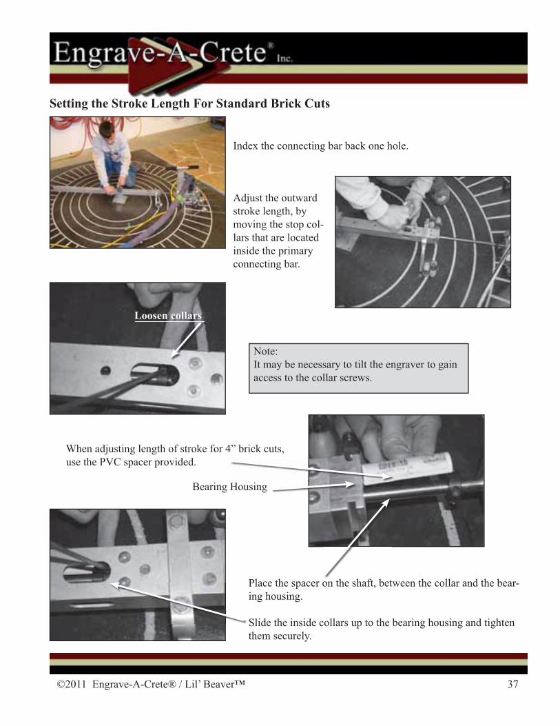
Setting the Stroke Length For Standard Brick Cuts
Index the connecting bar back one hole.
Adjust the outward stroke length, by moving the stop col-lars that are located inside the primary connecting bar.
When adjusting length of stroke for 4” brick cuts, use the PVC spacer provided.
Note:It may be necessary to tilt the engraver to gain access to the collar screws.
Loosen collars
Place the spacer on the shaft, between the collar and the bear-ing housing.
Slide the inside collars up to the bearing housing and tighten them securely.
Bearing Housing
38 1-417-924-2300
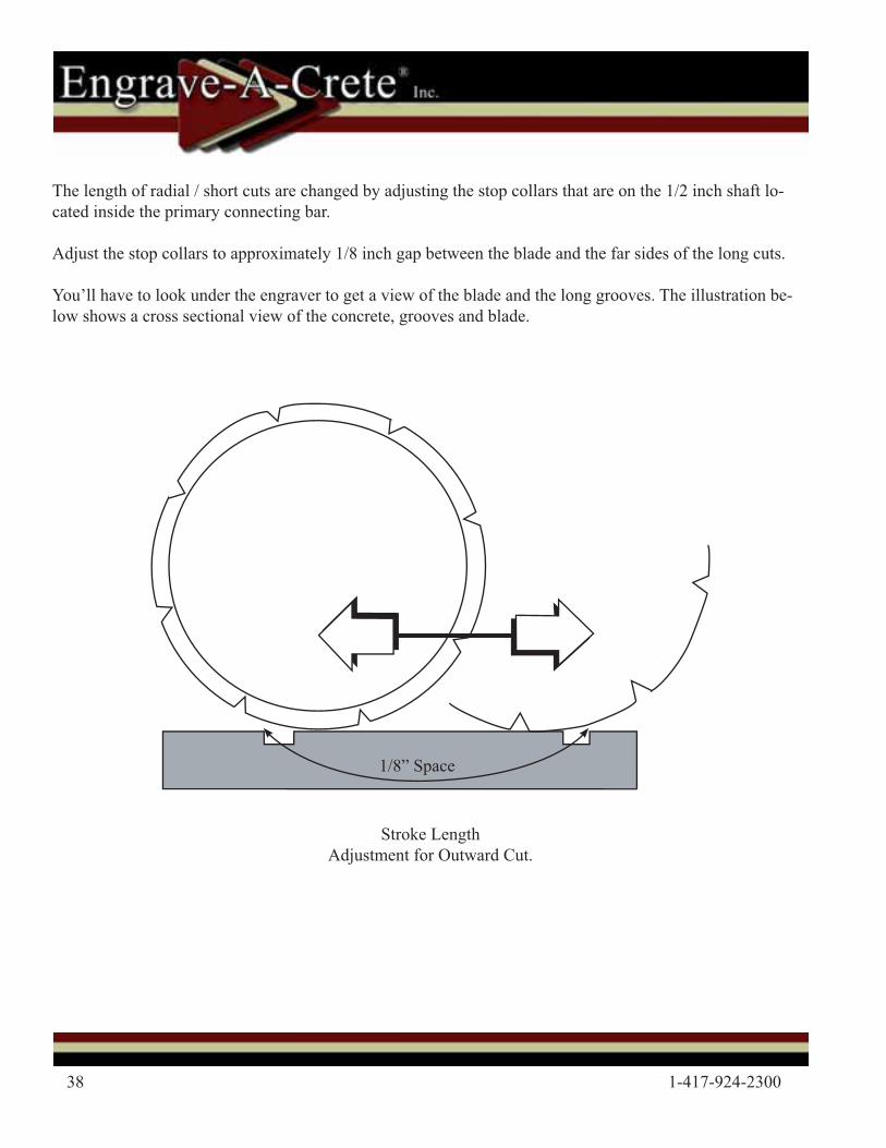
The length of radial / short cuts are changed by adjusting the stop collars that are on the 1/2 inch shaft lo-cated inside the primary connecting bar.
Adjust the stop collars to approximately 1/8 inch gap between the blade and the far sides of the long cuts.
You’ll have to look under the engraver to get a view of the blade and the long grooves. The illustration be-low shows a cross sectional view of the concrete, grooves and blade.
Stroke Length Adjustment for Outward Cut.
1/8” Space
©2011 Engrave-A-Crete® / Lil’ Beaver™ 39
Center PointerCenter Pointer
Center (3rd) Pointer 3rd Row
2nd Pointer 2nd Row
1st Pointer 1st Row
Center Pointer
Center Pointer
Center PointerCenter PointerCenter PointerCenter PointerCenter Pointer3rd R
ow C
enter Pointer
1st Row
1st Pointer
2nd Row
2nd Pointer
Center Pointer
Pencil MarksStart cutting on this row
12’
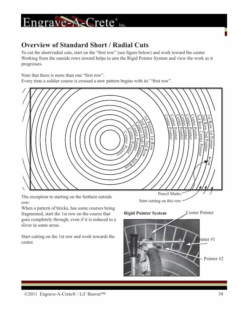
To cut the short/radial cuts, start on the “� rst row” (see � gure below) and work toward the center. Working from the outside rows inward helps to aim the Rigid Pointer System and view the work as it progresses.
Note that there is more than one “� rst row”. Every time a soldier course is crossed a new pattern begins with its’ “� rst row”.
Overview of Standard Short / Radial Cuts
The exception to starting on the furthest outside row:When a pattern of bricks, has some courses being fragmented, start the 1st row on the course that goes completely through; even if it is reduced to a sliver in some areas.
Start cutting on the 1st row and work towards the center.
Rigid Pointer SystemSystem
Pointer #2
Center Pointer
Pointer #1
CenterPointerCenter Pointer
Center ((3rd))Pointer3rdRow
2ndPointer2nd
Row
1st Pointer 1stRow
Center PointerCenter PointerCenter PointerCenter PointerCenter PointerCenter Pointer3rd
Row
CenterPointer
1st Row
1st Pointer
2ndR
ow2nd
Pointer
CenterPointer12’
40 1-417-924-2300
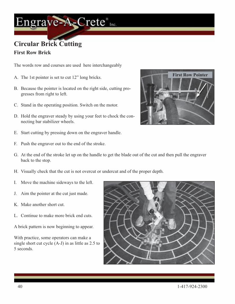
A. The 1st pointer is set to cut 12” long bricks.
B. Because the pointer is located on the right side, cutting pro-gresses from right to left.
C. Stand in the operating position. Switch on the motor.
D. Hold the engraver steady by using your feet to chock the con-necting bar stabilizer wheels.
E. Start cutting by pressing down on the engraver handle.
F. Push the engraver out to the end of the stroke.
G. At the end of the stroke let up on the handle to get the blade out of the cut and then pull the engraver back to the stop.
H. Visually check that the cut is not overcut or undercut and of the proper depth.
I. Move the machine sideways to the left.
J. Aim the pointer at the cut just made.
K. Make another short cut.
L. Continue to make more brick end cuts.
A brick pattern is now beginning to appear.
With practice, some operators can make a single short cut cycle (A-J) in as little as 2.5 to 5 seconds.
First Row Brick
The words row and courses are used here interchangeably
First Row Pointer
Circular Brick Cutting
©2011 Engrave-A-Crete® / Lil’ Beaver™ 41
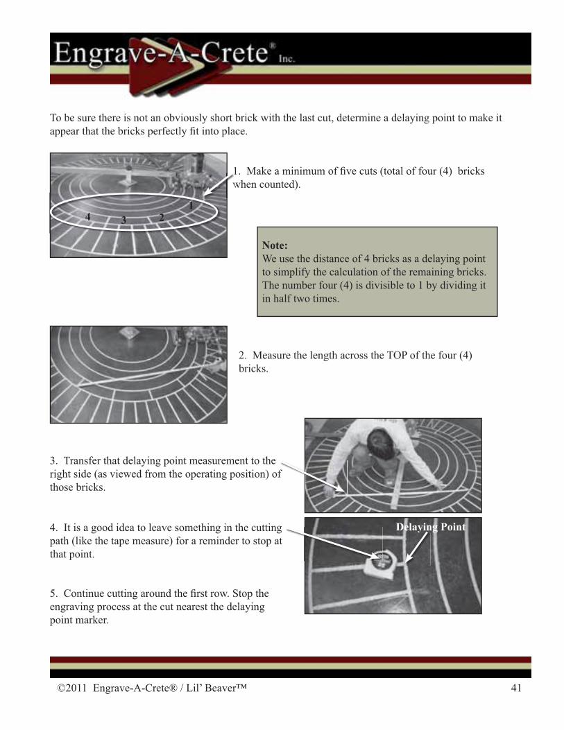
4. It is a good idea to leave something in the cutting path (like the tape measure) for a reminder to stop at that point.
To be sure there is not an obviously short brick with the last cut, determine a delaying point to make it appear that the bricks perfectly � t into place.
1. Make a minimum of � ve cuts (total of four (4) bricks when counted).
2. Measure the length across the TOP of the four (4) bricks.
3. Transfer that delaying point measurement to the right side (as viewed from the operating position) of those bricks.
Note:We use the distance of 4 bricks as a delaying point to simplify the calculation of the remaining bricks. The number four (4) is divisible to 1 by dividing it in half two times.
1w
Delaying Pointy
5. Continue cutting around the � rst row. Stop the engraving process at the cut nearest the delaying point marker.
f
1234
42 1-417-924-2300
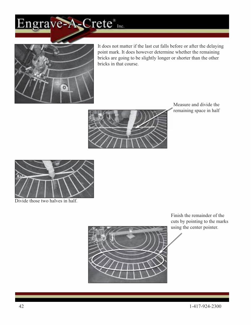
Finish the remainder of the cuts by pointing to the marks using the center pointer.
Measure and divide the remaining space in half
Divide those two halves in half.
It does not matter if the last cut falls before or after the delaying point mark. It does however determine whether the remaining bricks are going to be slightly longer or shorter than the other bricks in that course.
©2011 Engrave-A-Crete® / Lil’ Beaver™ 43
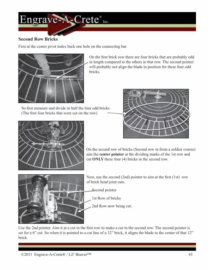
Second Row Bricks
Second pointerS
1st Row of bricks
2nd Row now being cut.
First at the center pivot index back one hole on the connecting bar.
Now, use the second (2nd) pointer to aim at the � rst (1st) row of brick head joint cuts.
On the � rst brick row there are four bricks that are probably odd in length compared to the others in that row. The second pointer will probably not align the blade in position for these four odd bricks.
On the second row of bricks (Second row in from a soldier course) aim the center pointer at the dividing marks of the 1st row and cut ONLY these four (4) bricks in the second row.
Use the 2nd pointer. Aim it at a cut in the � rst row to make a cut in the second row. The second pointer is set for a 6” cut. So when it is pointed to a cut line of a 12” brick, it aligns the blade to the center of that 12” brick.
123
4 123
4So � rst measure and divide in half the four odd bricks. (The � rst four bricks that were cut on the row)
44 1-417-924-2300
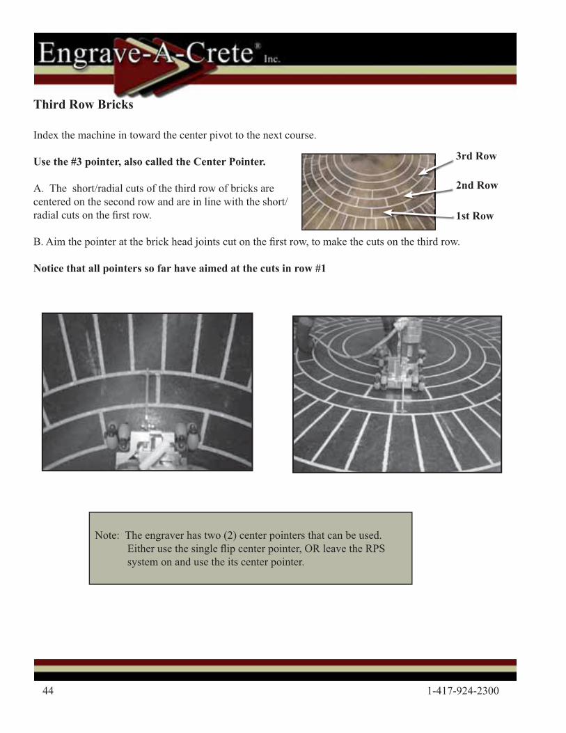
Third Row Bricks
Index the machine in toward the center pivot to the next course.
Use the #3 pointer, also called the Center Pointer.
A. The short/radial cuts of the third row of bricks are centered on the second row and are in line with the short/radial cuts on the � rst row.
B. Aim the pointer at the brick head joints cut on the � rst row, to make the cuts on the third row.
Notice that all pointers so far have aimed at the cuts in row #1
1st Row
2nd Row
3rd Row
Note: The engraver has two (2) center pointers that can be used. Either use the single � ip center pointer, OR leave the RPS system on and use the its center pointer.
©2011 Engrave-A-Crete® / Lil’ Beaver™ 45
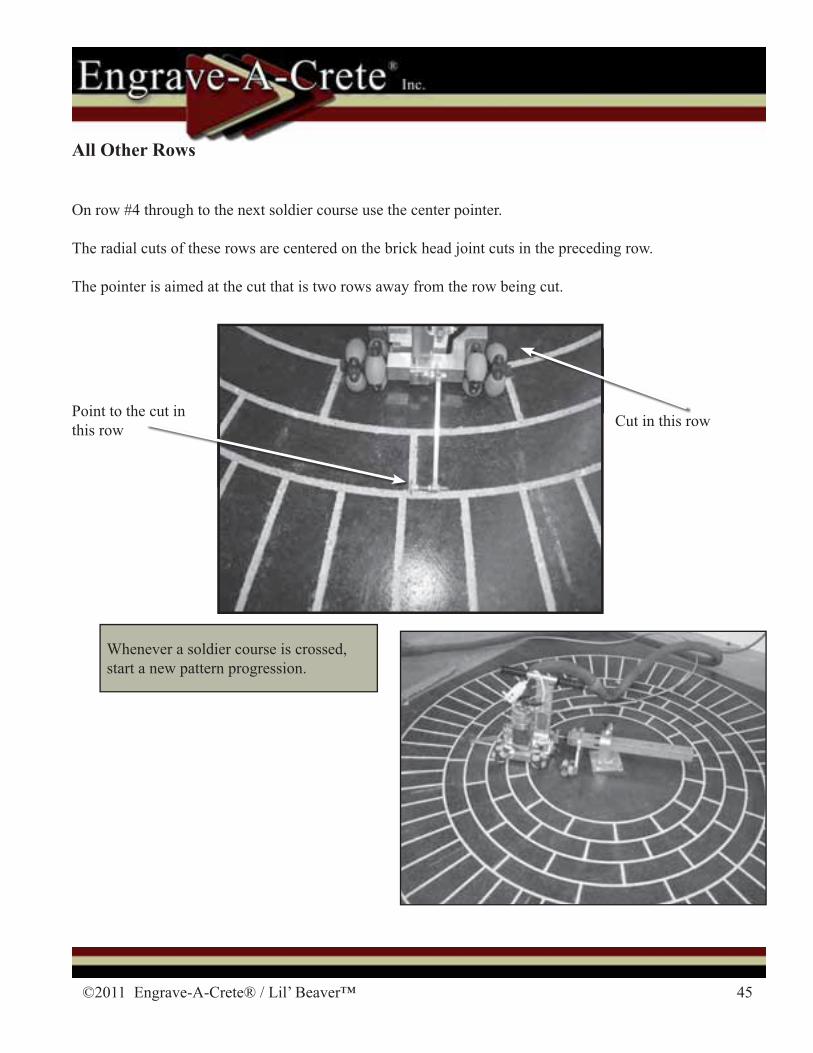
All Other Rows
On row #4 through to the next soldier course use the center pointer.
The radial cuts of these rows are centered on the brick head joint cuts in the preceding row.
The pointer is aimed at the cut that is two rows away from the row being cut.
Cut in this rowPoint to the cut in this row
Whenever a soldier course is crossed, start a new pattern progression.
46 1-417-924-2300
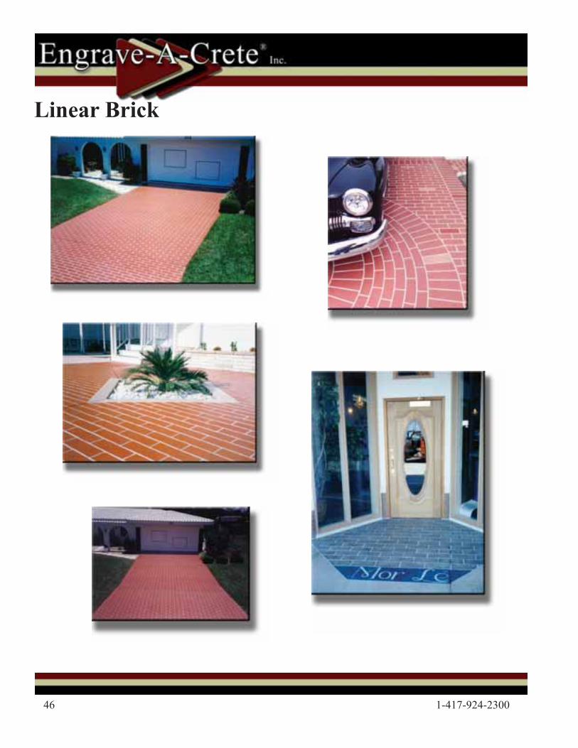
Linear Brick

©2011 Engrave-A-Crete® / Lil’ Beaver™ 47
Tools Needed
Hammer Drill
Concrete Anchoring Kit
Connecting Bar
Connecting Bar Stabilizer Linear Carriage
4’ or 8’ Linear Tracking
Primary Connecting Bar
Lil’ Beaver
48 1-417-924-2300
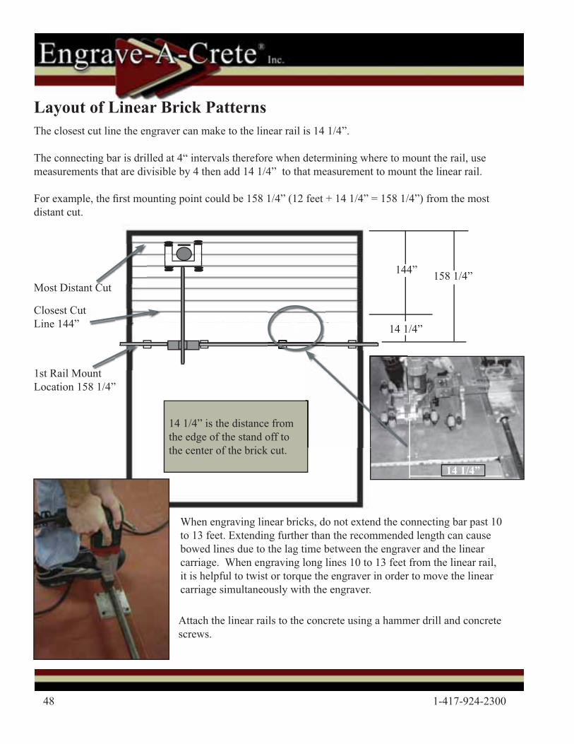
Layout of Linear Brick Patterns
Attach the linear rails to the concrete using a hammer drill and concrete screws.
14 1/4” is the distance from the edge of the stand off to the center of the brick cut.
The closest cut line the engraver can make to the linear rail is 14 1/4”.
The connecting bar is drilled at 4“ intervals therefore when determining where to mount the rail, use measurements that are divisible by 4 then add 14 1/4” to that measurement to mount the linear rail.
For example, the � rst mounting point could be 158 1/4” (12 feet + 14 1/4” = 158 1/4”) from the most distant cut.
When engraving linear bricks, do not extend the connecting bar past 10 to 13 feet. Extending further than the recommended length can cause bowed lines due to the lag time between the engraver and the linear carriage. When engraving long lines 10 to 13 feet from the linear rail, it is helpful to twist or torque the engraver in order to move the linear carriage simultaneously with the engraver.
Most Distant Cut
Closest Cut Line 144”
1st Rail Mount Location 158 1/4”
144”
14 1/4”
158 1/4”
14 1/4”
©2011 Engrave-A-Crete® / Lil’ Beaver™ 49
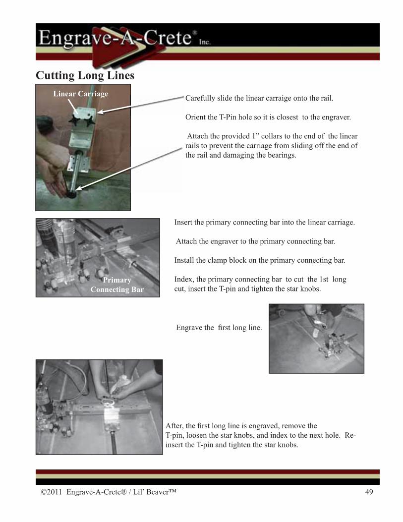
Carefully slide the linear carraige onto the rail.
Orient the T-Pin hole so it is closest to the engraver.
Attach the provided 1” collars to the end of the linear rails to prevent the carriage from sliding off the end of the rail and damaging the bearings.
Insert the primary connecting bar into the linear carriage.
Attach the engraver to the primary connecting bar.
Install the clamp block on the primary connecting bar.
Index, the primary connecting bar to cut the 1st long cut, insert the T-pin and tighten the star knobs.
Linear Carriage
PrimaryConnecting Bar
Engrave the � rst long line.
After, the � rst long line is engraved, remove the T-pin, loosen the star knobs, and index to the next hole. Re-insert the T-pin and tighten the star knobs.
Cutting Long Linesiage
50 1-417-924-2300
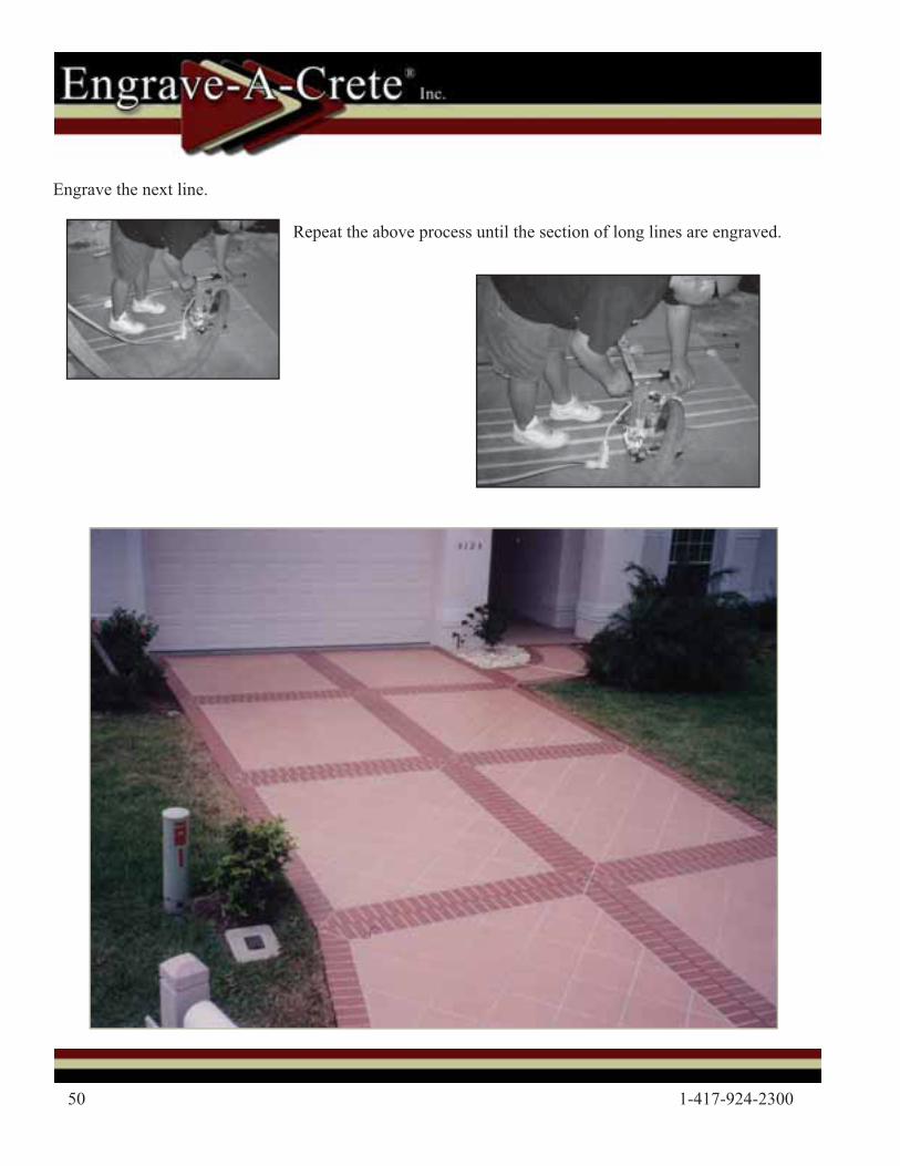
Engrave the next line.
Repeat the above process until the section of long lines are engraved.
©2011 Engrave-A-Crete® / Lil’ Beaver™ 51
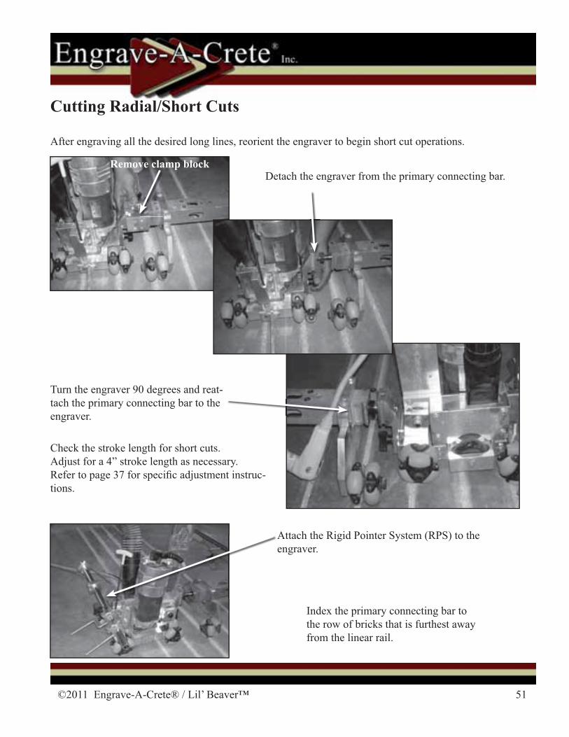
Index the primary connecting bar to the row of bricks that is furthest away from the linear rail.
Cutting Radial/Short Cuts
After engraving all the desired long lines, reorient the engraver to begin short cut operations.
Remove clamp block
Turn the engraver 90 degrees and reat-tach the primary connecting bar to the engraver.
Check the stroke length for short cuts.Adjust for a 4” stroke length as necessary. Refer to page 37 for speci� c adjustment instruc-tions.
Detach the engraver from the primary connecting bar.
Attach the Rigid Pointer System (RPS) to the engraver.
52 1-417-924-2300
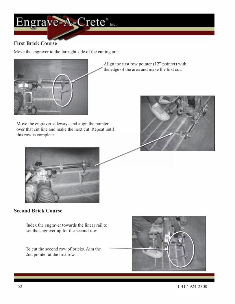
Move the engraver to the far right side of the cutting area.
Move the engraver sideways and align the pointer over that cut line and make the next cut. Repeat until this row is complete.
First Brick Course
Align the � rst row pointer (12” pointer) with the edge of the area and make the � rst cut.
Index the engraver towards the linear rail to set the engraver up for the second row.
To cut the second row of bricks. Aim the 2nd pointer at the � rst row.
Second Brick Course
©2011 Engrave-A-Crete® / Lil’ Beaver™ 53
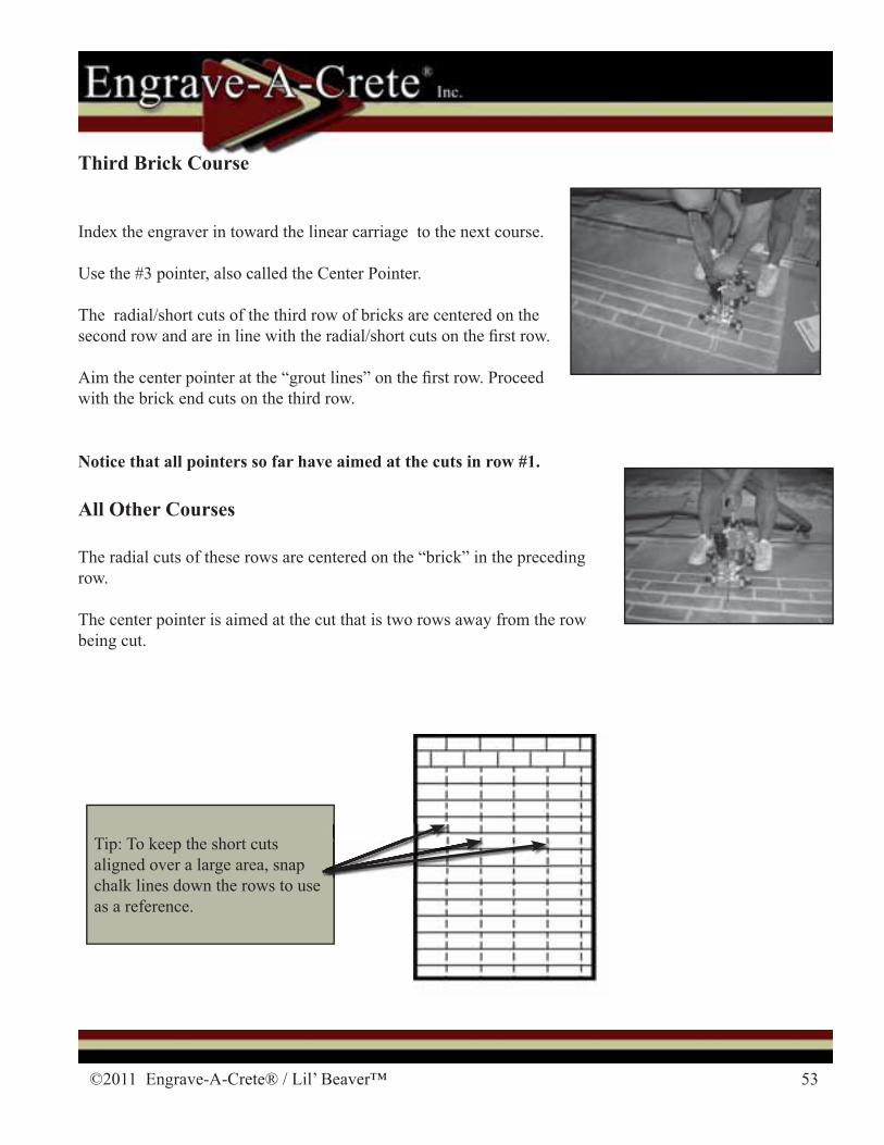
Third Brick Course
Index the engraver in toward the linear carriage to the next course.
Use the #3 pointer, also called the Center Pointer.
The radial/short cuts of the third row of bricks are centered on the second row and are in line with the radial/short cuts on the � rst row.
Aim the center pointer at the “grout lines” on the � rst row. Proceed with the brick end cuts on the third row.
All Other Courses
The radial cuts of these rows are centered on the “brick” in the preceding row.
The center pointer is aimed at the cut that is two rows away from the row being cut.
Notice that all pointers so far have aimed at the cuts in row #1.
Tip: To keep the short cuts aligned over a large area, snap chalk lines down the rows to use as a reference.
54 1-417-924-2300
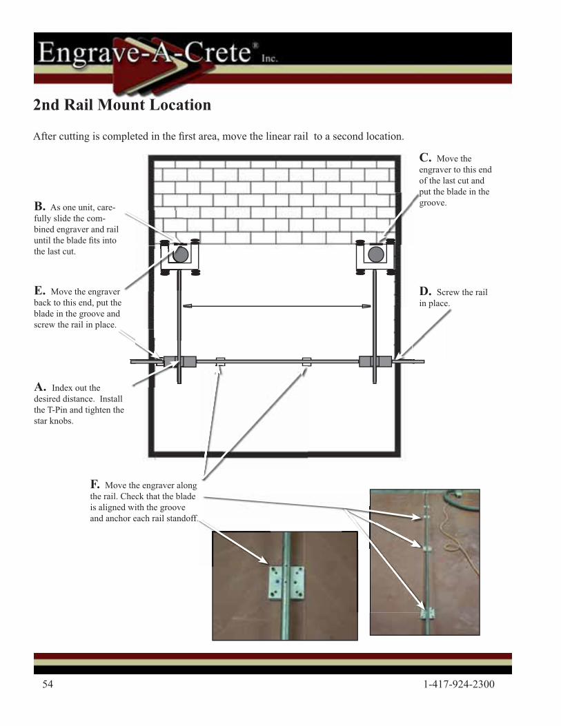
2nd Rail Mount Location
After cutting is completed in the � rst area, move the linear rail to a second location.
A. Index out the desired distance. Install the T-Pin and tighten the star knobs.
C. Move the engraver to this end of the last cut and put the blade in the groove.B. As one unit, care-
fully slide the com-bined engraver and rail until the blade � ts into the last cut.
pg
D. Screw the rail in place.
E. Move the engraver back to this end, put the blade in the groove and screw the rail in place.
F. Move the engraver along the rail. Check that the blade is aligned with the groove and anchor each rail standoff.
p
©2011 Engrave-A-Crete® / Lil’ Beaver™ 55
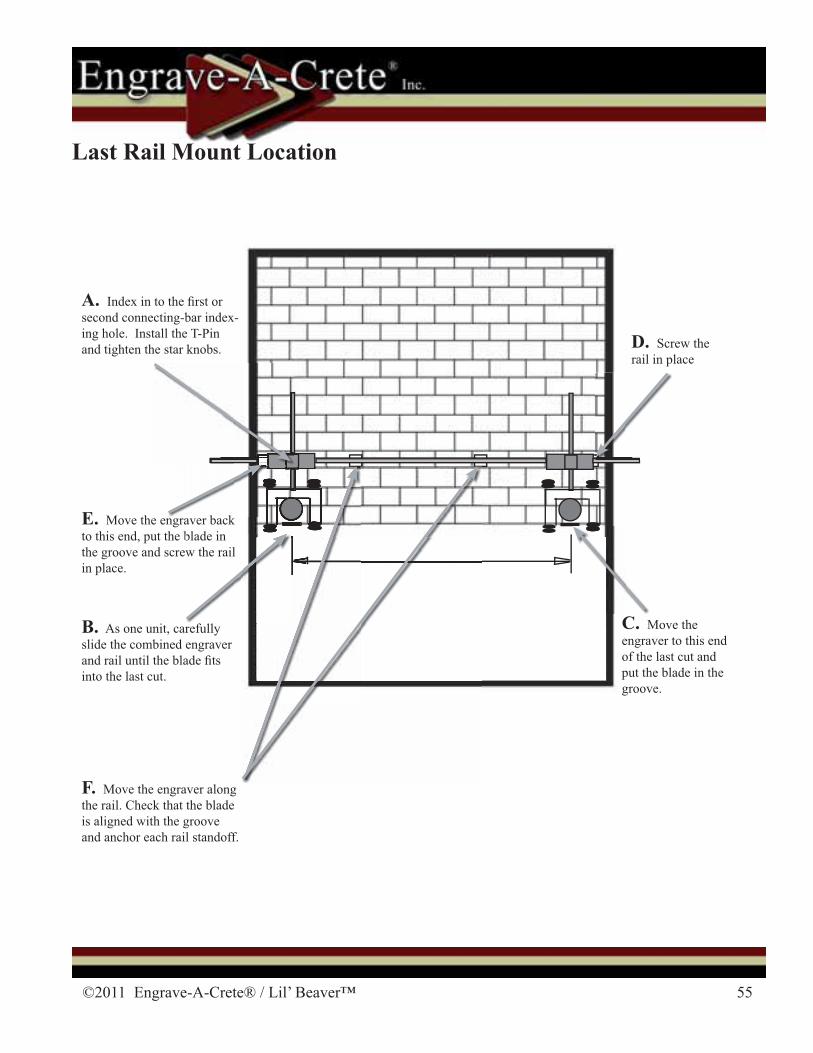
A. Index in to the � rst or second connecting-bar index-ing hole. Install the T-Pin and tighten the star knobs.
B. As one unit, carefully slide the combined engraver and rail until the blade � ts into the last cut.
E. Move the engraver back to this end, put the blade in the groove and screw the rail in place.
F. Move the engraver along the rail. Check that the blade is aligned with the groove and anchor each rail standoff.
C. Move the engraver to this end of the last cut and put the blade in the groove.
D. Screw the rail in place
blade inw the raill
b kk
Last Rail Mount Location
56 1-417-924-2300
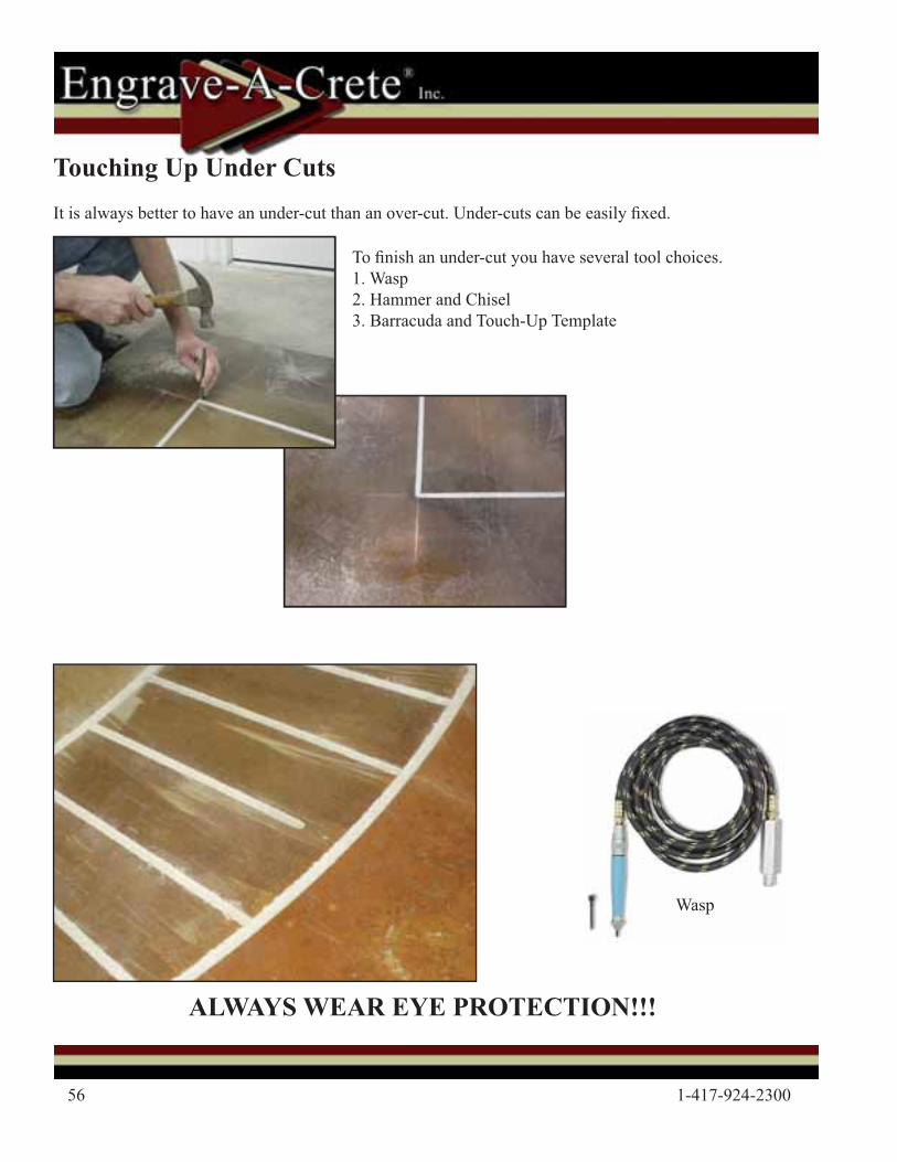
Touching Up Under CutsIt is always better to have an under-cut than an over-cut. Under-cuts can be easily � xed.
To � nish an under-cut you have several tool choices. 1. Wasp2. Hammer and Chisel3. Barracuda and Touch-Up Template
ALWAYS WEAR EYE PROTECTION!!!
Wasp
©2011 Engrave-A-Crete® / Lil’ Beaver™ 57
Miscuts
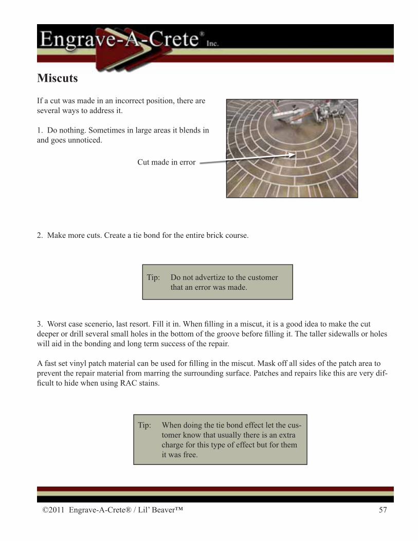
If a cut was made in an incorrect position, there are several ways to address it.
1. Do nothing. Sometimes in large areas it blends in and goes unnoticed.
Cut made in error
Tip: Do not advertize to the customer that an error was made.
3. Worst case scenerio, last resort. Fill it in. When � lling in a miscut, it is a good idea to make the cut deeper or drill several small holes in the bottom of the groove before � lling it. The taller sidewalls or holes will aid in the bonding and long term success of the repair.
A fast set vinyl patch material can be used for � lling in the miscut. Mask off all sides of the patch area to prevent the repair material from marring the surrounding surface. Patches and repairs like this are very dif-� cult to hide when using RAC stains.
2. Make more cuts. Create a tie bond for the entire brick course.
Tip: When doing the tie bond effect let the cus-tomer know that usually there is an extra charge for this type of effect but for them it was free.
58 1-417-924-2300
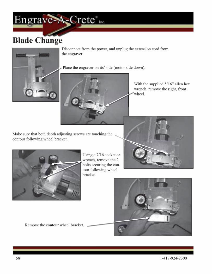
Blade Change
Place the engraver on its’ side (motor side down).
With the supplied 5/16” allen hex wrench, remove the right, front wheel.
Make sure that both depth adjusting screws are touching the contour following wheel bracket.
Using a 7/16 socket or wrench, remove the 2 bolts securing the con-tour following wheel bracket.
Remove the contour wheel bracket.
Disconnect from the power, and unplug the extension cord from the engraver.
©2011 Engrave-A-Crete® / Lil’ Beaver™ 59
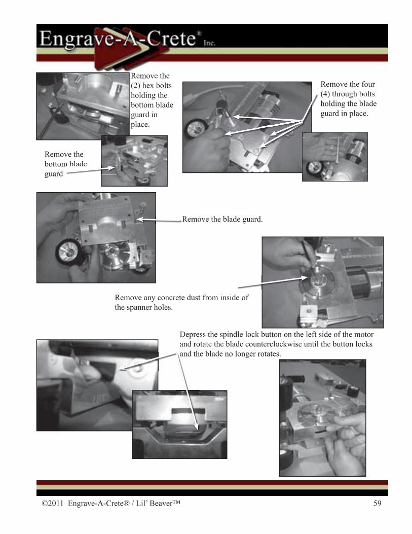
Remove the four (4) through bolts holding the blade guard in place.
Remove the blade guard.
Remove any concrete dust from inside of the spanner holes.
Depress the spindle lock button on the left side of the motor and rotate the blade counterclockwise until the button locks and the blade no longer rotates.and the
Remove the (2) hex bolts holding the bottom blade guard in place.
Remove the bottom blade guard
m blade
60 1-417-924-2300
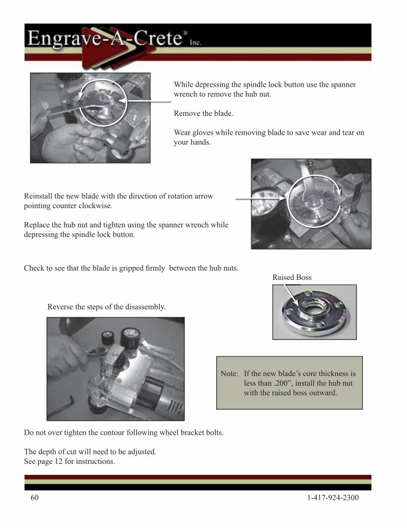
Reinstall the new blade with the direction of rotation arrow pointing counter clockwise.
Replace the hub nut and tighten using the spanner wrench while depressing the spindle lock button.
While depressing the spindle lock button use the spanner wrench to remove the hub nut.
Remove the blade.
Wear gloves while removing blade to save wear and tear on your hands.
Do not over tighten the contour following wheel bracket bolts.
The depth of cut will need to be adjusted. See page 12 for instructions.
Reverse the steps of the disassembly.
Note: If the new blade’s core thickness is less than .200”, install the hub nut with the raised boss outward.
Check to see that the blade is gripped � rmly between the hub nuts.Raised Boss
©2011 Engrave-A-Crete® / Lil’ Beaver™ 61
Tip: Use a 10/3 extension cord to get the most power to your equipment. Motors will run cooler, last lon-ger, be more powerful, circuit breakers will not be overloaded as easily and you’ll get the job done faster.
Tip: It’s best to use little or no lubrication. If needed, use WD-40 or light weight motor oil on the shafts, bearing, jack screws, and other places that need lubrication.
Tip: Make operations easier by adding on exta sections of vacuum hose. 12 to 20 feet or more is really nice. Also, install a Gortex® Clean Stream � lter on the vacuum for better operation.
Tip: Track free cutting done prior to other engraving will insure smoother Free-Of-The-Track operations. (The wheels won’t be bouncing over or side tracked by other grooves.)
Tip: The front pointer should be checked if... 1. It’s the � rst cut of the day. 2. A retaining collar comes loose. 3. It was accidentally kicked or bumped.
Tip: Be certain to check the secondary depth limiting screw before cutting. It is responsible for balancing the engraver for a smooth even cut.
Tip: Drilled anchor holes in the concrete can be � lled with a crack � ller or just left.
Tip: It is a good idea to snap all lines prior to cutting. This allows you to check that the layout is visually pleasing.
Tip: When doing free form curves start on a straight cut that leads into a curve. It makes alignment much easier.
Tip: To draw a line parallel to the edge of a slab, a handy tool is the edge parallel marker.
Tip: Usually the engraving process will begin with the long cuts.
Tip: When mounting a center pivot or linear track, if a screw will not seat to the base plate then the hole is not deep enough, debris is remaining in the hole, or the drill bit is worn from drilling many holes.
Tips, Tricks, & Troubleshooting
62 1-417-924-2300
Tip: Keep a mental or written note of the direction the center pivot base arrow is pointing. This will allow you to exactly reposition the center pivot if it is necessary to remove it before the engraving opera-tions are completed.
Tip: The center pivot star knob secures and tightens the connecting bar to the center pivot. If the star knob is not tight, it will cause a sloppy, ugly line. When cutting short cuts (radial cuts) a loose center pivot star knob will produce overcuts.
Tip: Connecting bar screws are NOT standard screws. Use of another type of screw will result in a loose � t between the bars. Resulting in miscuts.
Tip: The indexing holes are drilled 4” apart.
Tip: When aiming at a cut line with a pointer, you should be centered over the engraver. If you alter the viewing angle the width/length of the brick will change.
Tip: Soldier course cuts are not necessarily aligned with the cuts of any other courses.
Tip: In a circular or arcuate pattern, soldier courses break up the pattern and keep the other bricks from growing too long or too short.
Tip: In a circular or arcuate pattern, insert soldier courses as often as you like but generally there should put one at least every 8 to 12 brick courses.
Tip: On circular brick soldier courses, use the distance of 8 bricks as the delaying point to simplify the calculation of the remaining bricks. The number eight (8) is divisible to 1 by dividing it in half three times.
Tip: On the � rst row of a circular brick standard course, use the distance of 4 bricks as the delaying point to simplify the calculation of the remaining bricks. The number four (4) is divisible to 1 by dividing it in half three times.
Tip: It may be necessary to tilt the engraver to gain access to the collar screws.
Tip: The engraver has two (2) center pointers that can be used. Either use the single � ip center pointer, OR leave the RPS system on and use it’s center pointer.