the meaning of uml models - open research: open … · the meaning of uml models ... many helpful...
TRANSCRIPT
The Meaning of UML Models
Greg O’Keefe
A thesis submitted for the degree ofDoctor of Philosophy at
The Australian National University
September 2008revised February 2010


This thesis is my own original work.
Gregory C. O’Keefe
iii


Acknowledgements
Thanks to my supervisor Raj Gore for pushing me to do my own thing, and toclearly justify its research value. He had faith in me even when I did not. Thanksalso to Shayne Flint, Clive Boughton, Lynette Johns-Boast and Stephen Mellor formany helpful exchanges on engineering and model-driven software development.I talked modelling with innumerable people at the ECMDA-FA and MoDELS con-ferences in 2006, and I want to thank them all even though theyare too many toname. Thanks to Jean-Marc Jezequel and his team for welcoming me to their labbetween these conferences. The ANU has provided me with financial support andan exciting intellectual environment to work in. For this, Iam very grateful.
v

Abstract
The Unified Modelling Language (UML) is intended to express complex ideasin an intuitive and easily understood way. It is important because it is widelyused in software engineering and other disciplines. Although an official definitiondocument exists, there is much debate over the precise meaning of UML models.
In response, the academic community have put forward many different pro-posals for formalising UML, but it is not at all obvious how todecide betweenthem. Indeed, given that UML practitioners are inclined to reject formalisms asnon-intuitive, it is not even obvious that the definition should be “formal” at all.Rather than searching for yet another formalisation of UML,our main aim is todetermine what would constitute a good definition of UML.
The first chapter sets the UML definition problem in a broad context, relatingit to work in logic and the philosophy of science. More specific conclusions aboutthe nature of model driven development are reached in the beginning of Chapter 2.We then develop criteria for a definition of UML. Applying these criteria to theexisting definition, we find that it is lacking in clarity. We then set out to test theprecision of the definition. The test is to take an apparentlyinconsistent model, anddetermine whether it really is inconsistent according to the definition.
Many people have proposed that UML models are graphs, but fewhave justi-fied this choice using the official definition of UML. We begin Chapter 3 by argu-ing from the official definition that UML models are graphs andthat instantiationis a graph homomorphism into an interpretation functor. Theofficial definition ofUML defines the semantics against its abstract syntax, whichis in turn defined bya UML model. Chapters 3 and 4 prepare for our test by resolvingthis apparentcircularity. The result is a semantics for the metamodel fragment of the language.
In Chapter 5, we find, contrary to popular belief, that the official definition doesprovide sufficient semantics to classify the example model as inconsistent. More-over, the sustained study of the semantics in Chapters 3 to 5 confirms our initialargument that the semantic domain is graphs. The Actions arethe building blocksof UML’s prescriptive dynamics. We see that they can be naturally defined as graphtransformation rules. Sequence diagrams are the main example of descriptive dy-namics, but we find that their official semantics are broken. The “recorded history”approach should be replaced, we suggest, by a graph-oriented dynamic logic.
Chapter 6 presents our early work on dynamic logic for UML sequence dia-grams and further explores the proposed semantic repairs. In Chapter 7, guidedby the criteria developed in Chapter 2, we critically surveythe UML formalisationliterature and conclude that an existing body of graph transformation based workknown as “dynamic metamodelling” is very close to what is required.
The final chapter draws together our conclusions. It proposes a category the-oretic construction to merge models of the syntax and semantic domain, yieldinga type graph for the graph transformation system which defines the dynamic se-mantics of the language. Finally, it outlines the further work required to realise asatisfactory definition of UML.
vii


Intended Audience
The dissertation is deliberately written for workers in model driven developmentwho do not necessarily have a strong mathematical background. Where mathe-matics is used, the ideas are mostly explained in plain English as well. Some ofthe mathematical ideas are not fully developed, but merely indicate what existingresearch may be relevant.
ix
Contents
1 Logic and Modelling 11.1 Logic . . . . . . . . . . . . . . . . . . . . . . . . . . . . . . . . 21.2 Conceptual Modelling . . . . . . . . . . . . . . . . . . . . . . . 31.3 Models and Statements . . . . . . . . . . . . . . . . . . . . . . . 41.4 TheUML Model . . . . . . . . . . . . . . . . . . . . . . . . . . 8
2 The Purpose of UML and Criteria for a Definition 112.1 What is a Model? . . . . . . . . . . . . . . . . . . . . . . . . . . 122.2 Working with Ideas . . . . . . . . . . . . . . . . . . . . . . . . . 192.3 Diagrams and Languages . . . . . . . . . . . . . . . . . . . . . . 202.4 Semantics . . . . . . . . . . . . . . . . . . . . . . . . . . . . . . 242.5 Metamodelling and Reflection . . . . . . . . . . . . . . . . . . . 272.6 Semantic Variation Points . . . . . . . . . . . . . . . . . . . . . . 292.7 The UML Definition Evaluated . . . . . . . . . . . . . . . . . . . 302.8 Conclusion . . . . . . . . . . . . . . . . . . . . . . . . . . . . . 32
3 Semantic Preliminaries 343.1 The Semantic Domain . . . . . . . . . . . . . . . . . . . . . . . 353.2 Object Diagrams and System States . . . . . . . . . . . . . . . . 383.3 Class Diagrams and Models . . . . . . . . . . . . . . . . . . . . 413.4 The Metamodel . . . . . . . . . . . . . . . . . . . . . . . . . . . 503.5 Reflection . . . . . . . . . . . . . . . . . . . . . . . . . . . . . . 543.6 Reconciliation of the Two Views . . . . . . . . . . . . . . . . . . 593.7 Conclusion . . . . . . . . . . . . . . . . . . . . . . . . . . . . . 64
4 Breaking the Symmetry of Association Ends 664.1 Naive Symmetry . . . . . . . . . . . . . . . . . . . . . . . . . . 674.2 Derived Property Values . . . . . . . . . . . . . . . . . . . . . . 734.3 Conclusion . . . . . . . . . . . . . . . . . . . . . . . . . . . . . 77
5 Testing the Definition 795.1 An Apparently Inconsistent Model . . . . . . . . . . . . . . . . . 805.2 The Definition of UML and our Class Model . . . . . . . . . . . 815.3 UML Dynamics . . . . . . . . . . . . . . . . . . . . . . . . . . . 87
x
5.4 Emergent Behavior . . . . . . . . . . . . . . . . . . . . . . . . . 925.5 Causation and Behavior . . . . . . . . . . . . . . . . . . . . . . . 985.6 Graph Transformation and Action . . . . . . . . . . . . . . . . . 1055.7 Consistency . . . . . . . . . . . . . . . . . . . . . . . . . . . . . 109
6 Dynamic Logic for UML Consistency 1156.1 Dynamic Logic . . . . . . . . . . . . . . . . . . . . . . . . . . . 1166.2 The Model as Dynamic Logic Formulae . . . . . . . . . . . . . . 1196.3 Weaving and Consistency . . . . . . . . . . . . . . . . . . . . . . 1246.4 Interactions as Dynamic Formulae . . . . . . . . . . . . . . . . . 128
7 The UML Formalisation Literature 1307.1 Relational and Entity-Relationship Models . . . . . . . . . .. . . 1317.2 Graph Transformation . . . . . . . . . . . . . . . . . . . . . . . . 1367.3 Logics . . . . . . . . . . . . . . . . . . . . . . . . . . . . . . . . 1487.4 Other Techniques . . . . . . . . . . . . . . . . . . . . . . . . . . 1547.5 Comparison and Conclusion . . . . . . . . . . . . . . . . . . . . 163
8 How UML Should be Defined 1658.1 What a UML Model Means . . . . . . . . . . . . . . . . . . . . . 1668.2 Towards a Well Defined and Understood UML . . . . . . . . . . . 1718.3 Findings . . . . . . . . . . . . . . . . . . . . . . . . . . . . . . . 1758.4 Conclusion . . . . . . . . . . . . . . . . . . . . . . . . . . . . . 178
xi

Chapter 1
Logic and Modelling
The Unified Modelling Language (UML) is widely used in software engineeringand other disciplines to express complex ideas in a way that can be easily under-stood. However, practical problems arise because the meaning of UML models isnot well defined.
A UML model ought to be the tangible form of a shared understanding of somesubject area. Discussion and negotiation are required to achieve such a sharedunderstanding, and we should expect that models would be part of this dialog.Imagine three people working together to model some subject. Alan proposes afragment of a model to represent certain phenomena, Betty points out an examplethat does not seem to be covered, Colin suggests a modification to the model thatresolves the difficulty. This process can only work if the meaning of the modelsis clear. In current practice, arguments and confusion about the meaning of themodels consume much of the available time. Apparent agreements can collapseafter much has been invested in them, because the same model is understood indifferent ways by different people.
The aim of the present work is to find and justify a clear and precise definitionof UML, which will facilitate understanding and agreement.We call this “thedefinition problem”. The justification part of this task is important. A myriad ofproposals exist in the literature but it is not obvious what would make one a betterchoice than another.
Absolute precision of meaning has been achieved by formal logic. The limita-tion is that formal logic can only talk about abstract structures. If we wish to talkabout the real world, we must assume that it resembles an abstract structure. Thelanguages of formal logic are occasionally used in practical applications, usuallywhen the certainty of formal deduction or semantic analysisis required. Theselanguages are not used very widely though, because few people can understandthem.
We aim to combine the precision of formal logic with the comprehensibilityof UML, to achieve a language more useful than UML is in its current state. Thischapter provides the background needed to understand the problem that we aim
1

to solve. In the first two sections, we introduce logic and thekind of modellingexemplified by UML. The third subsection relates the two fields by looking at thenotion of “model” in logic, and the use of models and logic in engineering and thephilosophy of science. The final section makes use of this background to explainour project from another perspective.
1.1 Logic
Although logic has a very long history going back to Aristotle around 350BC,its modern mathematical form emerged around the beginning of the 20th centurywith the work of Frege, Hilbert, Russell and Whitehead, and Tarski. The mainmotivation for this development was the foundations of mathematics. In orderto eliminate questionable appeals to intuition, mathematical reasoning was to bereduced to a purely mechanical process, at least in principle. This thinking was akey influence on the development of the computer [Dav01].
Logic is the study of good reasoning. It seeks techniques fordetermining thevalidity of arguments. An argument consists of zero or more statements calledpremises, and a statement called the conclusion. An argument is valid if the con-clusion is true in every situation where all the premises aretrue. Reasoning is anattempt to show that an argument is valid.
In formal logic, the statements of English or other natural languages are repre-sented by strings of symbols called formulae. A formal language is a set of stringsof a given set of symbols. Like programming languages, the languages of formallogic are usually defined by a generative grammar. Such grammars have base rules,such as “P is a formula” and recursive rules such as “ifA andB are formulae, thenA&B is a formula”. When a system is defined in this way, it is possible to provethings about it using mathematical induction.
Reasoning is represented in formal logic by a purely syntactic deduction calcu-lus, which defines a notion of proof. Each step in a formal proof is an applicationof one of the deductive rules of the calculus. Atheory is defined to be a set offormulae which contains every formula that can be deduced from it. We can defineparticular theories by giving a set of axioms, just as we do informally in mathemat-ics and science. Precisely defining a notion of proof allows us to step outside thedeductive system, and prove ideas from a higher “level”. Proving properties abouttheories is called metamathematics. Proving properties about deductive systems asa whole is called metatheory.
The formal languages of logics are usually very simple, withas few symbolsand formation rules as possible. This makes it simpler to do these metatheoreticproofs about the systems, but it does not make the formulae easier to read. Math-ematics usually seeks deep consequences of simple ideas, and these simple ideascan often be expressed quite concisely using formulae of a symbolic logic. Prac-tical problems on the other hand more often involve very complex ideas, but donot need to reason very deeply about them. Verification of computer chips is an
2
example of this phenomenon.Among the most important properties a deductive system can have are sound-
ness, completeness and decidability. A deductive system issaid to be sound if everyprovable argument is valid, and complete if every valid argument is provable. Alogic is decidable if there is an algorithm which can determine the validity of eachargument. These definitions rest on the notion of validity, which in turn relies onthe notion of a formula being true in a situation.
The “situations” are also formalised in mathematical logicas a structure, orinterpretation. This is a collection of individuals and tells us which individual eachconstant represents, and what relation over the individuals each relation-symbolstands for. Given this definition, it is possible to actuallydefinewhat it means for aformula to be true in a given structure. It is this mathematical definition of truth (seeeg. [Hod97,§2.1]) which justifies our claim that the meaning of logical languagesis absolutely precise. When a structure makes all the formulae in a theory true, wecall that structure amodelof the theory.
Section 6.1 will briefly introduce propositional, predicate and dynamic logics.
1.2 Conceptual Modelling
Large software projects are notoriously prone to failure, and to exceeding theirbudgets and timetables. Indeed “...the majority of industrial software projects arenever completed but are cancelled either due to cost overruns or failure to deliverthe promised functionality” [Sel01]. Despite the high costof development, theevolution or maintenance of computer systems is often 3 or 4 times their initialdevelopment cost [Som01,§1.1.7]. The main reason for these problems is thecomplexity of the required systems, and this complexity continues to grow. Muchof the research in software languages is intended to help manage this complexity.
The underlying concepts of programming languages have gonefrom pure ma-chine notions of assembly languages to useful abstract mathematical ideas likefunctions and lists to more natural real world ideas like objects and messages.Techniques of abstraction and localisation have been introduced such as generalisa-tion, encapsulation, modules and aspects. Object orientedprogramming languagesbecame dominant during the 1980’s, but their origins go backanother 20 years[DN66].
Research in databases has also aimed to manage complexity. In particular, thecomplexity of information structure. The relational model[Cod70] proved to be auseful abstraction, providing a simple but expressive half-way point between appli-cation level thinking and implementation details. Peter Chen’s 1976 paper [Che76]introduced the entity-relationship model, a natural way ofdescribing the informa-tion of the application domain in terms of the entities that can exist and the rela-tionships that can hold between them. Translations were defined from this model tothe major implemented database models, including the relational model. Chen alsoprovided a diagrammatic notation for this model, the entity-relationship diagram.
3
We examine the relational and entity-relationship models in Section 7.1. This workbecame the paradigm for a new research field called conceptual modelling, whichalso drew inspiration from work on “knowledge representation” in artificial intelli-gence. Conceptual modelling researchers are often housed in information systemsdepartments in commerce faculties, whereas model driven development is moreoften sponsored by computer science and engineering departments. There wouldbe benefits for all in increased collaboration between thesecamps.
Software engineers were also beginning to use diagrams and conceptual ab-stractions to capture and understand system requirements in the 1970’s. The Struc-tured Analysis and Design Technique (SADT) was presented asa “language forcommunicating ideas” [Ros77]. It was widely used, and influenced the later de-facto standard “data flow diagrams” [DeM78].
Object oriented visual modelling was underway by 1980 in thework of JohnMylopoulos and his collaborators [Myl80]. This paper also introduces many of theideas now found in UML: metaclasses, views, aggregation, constraints, reflection,executable models, code generation and the reification of procedure executions.
This style of modelling was popularised in the late 1980’s [SM88] and early1990’s by software “methodologists”. Among these were the “three amigos” GradyBooch, Jim Rumbaugh and Ivar Jacobson [Boo94, RBP+91, J+92]. These method-ologists created UML in 1994 and 1995 by merging their different but similarvisual object oriented modelling languages. Control of thelanguage definitionpassed from the Rational corporation (now part of IBM) to theindustry consor-tium the Object Management Group (OMG). The current versionof UML, 2.1, isintended to support model driven software development. TheOMG intends thatmodelling should replace programming as the primary activity of software devel-opment [MM03]. Model transformations will generate code from models just ascompilers generate machine code from high level language programs.
UML has a concrete syntax consisting of 13 types of diagram and a textualconstraint language. Its abstract syntax is defined using a “metamodel”, whichis itself a UML model1. The metamodel is very large, consisting of over 200classes and 9 levels of generalisation. The metamodel is organised into packageswhich form 4 “compliance levels” using different package combination concepts.Although at first sight the diagrams seem quite intuitive, all this complexity makesit very difficult to achieve a clear understanding of the concepts underlying thelanguage, and hence the meaning of its diagrams [FGDTS06, BG04].
1.3 Models and Statements
The astute reader may have noticed that we have already used the word “model”in at least three different ways. Analysing such ambiguities can easily result ina boring waste of ink. However, there are two main benefits we hope to gain by
1In fact, the UML metamodel is a MOF [Obj06a] model. MOF is a subset of the static part ofUML, specialised for metamodelling.
4
Model Description Modelspecifies // Target SystemModel //resemblesoo
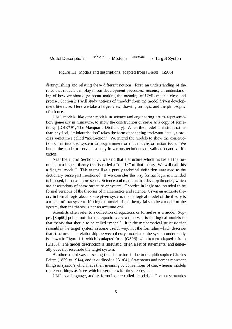
Figure 1.1: Models and descriptions, adapted from [Gie88] [GS06]
distinguishing and relating these different notions. First, an understanding of theroles that models can play in our development processes. Second, an understand-ing of how we should go about making the meaning of UML models clear andprecise. Section 2.1 will study notions of “model” from the model driven develop-ment literature. Here we take a larger view, drawing on logicand the philosophyof science.
UML models, like other models in science and engineering are“a representa-tion, generally in miniature, to show the construction or serve as a copy of some-thing” [DBB+91, The Macquarie Dictionary]. When the model is abstract ratherthan physical, “miniaturisation” takes the form of shedding irrelevant detail, a pro-cess sometimes called “abstraction”. We intend the models to show the construc-tion of an intended system to programmers or model transformation tools. Weintend the model to serve as a copy in various techniques of validation and verifi-cation.
Near the end of Section 1.1, we said that a structure which makes all the for-mulae in a logical theory true is called a “model” of that theory. We will call thisa “logical model”. This seems like a purely technical definition unrelated to thedictionary sense just mentioned. If we consider the way formal logic is intendedto be used, it makes more sense. Science and mathematics develop theories, whichare descriptions of some structure or system. Theories in logic are intended to beformal versions of the theories of mathematics and science.Given an accurate the-ory in formal logic about some given system, then a logical model of the theory isa model of that system. If a logical model of the theory fails to be a model of thesystem, then the theory is not an accurate one.
Scientists often refer to a collection of equations or formulae as a model. Sup-pes [Sup60] points out that the equations are a theory, it is the logical models ofthat theory that should to be called “model”. It is the mathematical structure thatresembles the target system in some useful way, not the formulae which describethat structure. The relationship between theory, model andthe system under studyis shown in Figure 1.1, which is adapted from [GS06], who in turn adapted it from[Gie88]. The model description is linguistic, often a set ofstatements, and gener-ally does not resemble the target system.
Another useful way of seeing the distinction is due to the philosopher CharlesPeirce (1839 to 1914), and is outlined in [Als64]. Statements and names representthings assymbolswhich have their meaning by conventions of use, whereas modelsrepresent things asiconswhich resemble what they represent.
UML is a language, and its formulae are called “models”. Given a semantics
5
of the language, a UML “model” specifies a model which resembles the targetsystem. That is, in the terminology of Figure 1.1, a UML “model” is actually amodel description.
This would appear to be the kind of error that Suppes warns against: confusinga model description with a model. I will argue that UML is an exceptional languagewhose formulae can justifiably be thought of as models.
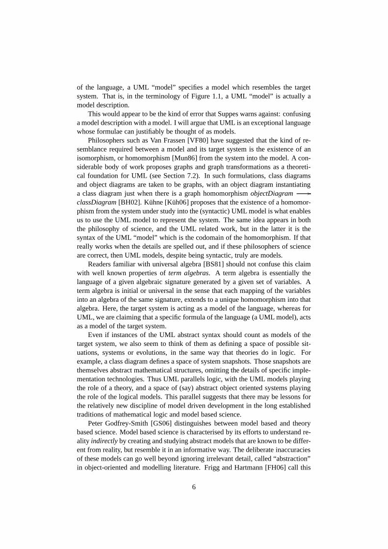
Philosophers such as Van Frassen [VF80] have suggested thatthe kind of re-semblance required between a model and its target system is the existence of anisomorphism, or homomorphism [Mun86] from the system into the model. A con-siderable body of work proposes graphs and graph transformations as a theoreti-cal foundation for UML (see Section 7.2). In such formulations, class diagramsand object diagrams are taken to be graphs, with an object diagram instantiatinga class diagram just when there is a graph homomorphismobjectDiagram //
classDiagram[BH02]. Kuhne [Kuh06] proposes that the existence of a homomor-phism from the system under study into the (syntactic) UML model is what enablesus to use the UML model to represent the system. The same idea appears in boththe philosophy of science, and the UML related work, but in the latter it is thesyntax of the UML “model” which is the codomain of the homomorphism. If thatreally works when the details are spelled out, and if these philosophers of scienceare correct, then UML models, despite being syntactic, truly are models.
Readers familiar with universal algebra [BS81] should not confuse this claimwith well known properties ofterm algebras. A term algebra is essentially thelanguage of a given algebraic signature generated by a givenset of variables. Aterm algebra is initial or universal in the sense that each mapping of the variablesinto an algebra of the same signature, extends to a unique homomorphism into thatalgebra. Here, the target system is acting as a model of the language, whereas forUML, we are claiming that a specific formula of the language (aUML model), actsas a model of the target system.
Even if instances of the UML abstract syntax should count as models of thetarget system, we also seem to think of them as defining a spaceof possible sit-uations, systems or evolutions, in the same way that theories do in logic. Forexample, a class diagram defines a space of system snapshots.Those snapshots arethemselves abstract mathematical structures, omitting the details of specific imple-mentation technologies. Thus UML parallels logic, with theUML models playingthe role of a theory, and a space of (say) abstract object oriented systems playingthe role of the logical models. This parallel suggests that there may be lessons forthe relatively new discipline of model driven development in the long establishedtraditions of mathematical logic and model based science.
Peter Godfrey-Smith [GS06] distinguishes between model based and theorybased science. Model based science is characterised by its efforts to understand re-ality indirectlyby creating and studying abstract models that are known to bediffer-ent from reality, but resemble it in an informative way. The deliberate inaccuraciesof these models can go well beyond ignoring irrelevant detail, called “abstraction”in object-oriented and modelling literature. Frigg and Hartmann [FH06] call this
6
“Aristotelian idealisation”, and distinguish it from “Galilean idealisation” wheredeliberately false simplifying assumptions are made. Examples include friction-less planes, omniscient agents and discrete generations ofpopulation. A furtherkind of simplification is “approximation”, in which the description is simplifiedrather than the model itself. The motivating example of thisis using just the firstfew terms of a polynomial expansion of a function. This kind of approximation willbe seen in Section 7.3, where we discuss applications of logical model-checkingto UML verification problems. Model checking uses languagesof limited expres-siveness so that the checking problem will be decidable and tractable. Since UMLis much more expressive than these languages, it really is only an approximationof the UML model that is verified by such techniques.
The production of code in model driven development does not seem to bestrongly model-based in this way. The models used for code generation employAristotelian idealisation by ignoring implementation details, but Galilean ideali-sation and approximation do not seem to be used. The reason isthat these areprescriptive rather than descriptive. The systems modelled in science are alreadythere, but in engineering, we make models of things that are not there, but whichwe would like to have. A descriptive model can describe an existing system in aninaccurate but useful way. A prescriptive model can not be inaccurate, it simplydescribes the wrong system, a system which will probably notsatisfy its require-ments.
There is also a role for descriptive models in computer system work. Very sim-plified models including some false assumptions, are used for performance predic-tion, capacity planning and software metrics. In each case,the model resemblesthe target system in a specific and useful way. These exercises do not usually useUML or other model driven development languages, but they could. Model drivenreverse engineering, and business process re-engineeringbegin by developing adescriptive model, then switch to using it prescriptively.MDD also makes use ofdescriptive models, for example in testing.
Although any kind of statement can be used in either way, a prescriptive state-ment is not very useful if we do not have control over the phenomena the statementtalks about. Pamela Zave and Michael Jackson [ZJ97, GGJZ00]suggest that thevocabulary used in a system development project should be classified accordingto who controls the phenomenon it describes: the environment or the system. Inaddition, they record whether or not the phenomenon is visible to the party thatdoes not control it. Requirements should be written using vocabulary visible toboth system and environment, that is, in the system boundary. Specifications arewritten using vocabulary that is controlled by the system, because that is what wehave power to implement. Models should only be used prescriptively when we arein control of what is modelled.
In Section 5.3 we will apply this prescriptive/descriptivedistinction withinUML, claiming that whilst state machines and activities canbe used prescriptively,sequence diagrams ought only to be used descriptively. The actions defined in aUML activity determine what objects of the given class do, that is, they are inher-
7
ently prescriptive. On the other hand, the objects in an executing UML system arenot controlled by sequence diagrams. This distinction willguide us when choos-ing appropriate ways of precisely defining the meanings of the different parts of aUML model.
We see another lesson which model-based science can offer model driven de-velopment. Model-based science is as interested in the properties of the models asit is in reality itself, “for example, evolutionary biologyhas been very concernedwith questions about which model systems can include the evolution of variouskinds of altruism, cooperation, and reproductive restraint” [GS06]. A simple char-acterisation of the models which give rise to one of these properties may yieldinsights into how it arose in nature. It is possible that troubling phenomena incomputer based systems could be mastered by a similar approach.
Mathematical logic also studies the models which satisfy each given theory.This branch of logic is known as “model theory” which “is about the classificationof mathematical structures, maps and sets by means of logical formulas” [Hod97,Page vii]. One could imagine an analogous study of the classification of abstractobject oriented systems by means of UML models. Insights from such a studycould lead to improvements in modelling practice, and in themodelling languagesthemselves. The biggest obstacle to such a study is that it iscurrently not at allclear what these abstract object oriented systems actuallyare.
1.4 The UML Model
We discussed the usual dictionary usage of the word “model” in Section 1.3. Withsome qualification, we have seen that UML models are models inthis sense. How-ever, this sense seems different to the way it is used in the titles of two importantpapers discussed in Section 1.2: “The Relational Model for Large Shared DataBanks” [Cod70] and “The Entity-Relationship Model: Towarda Unified View ofData” [Che76]. The models here are general schemes for organising data, or equiv-alently, a set of “ontological assumptions” [Myl98] for viewing the world. The re-lational model assumes that the world consists of relations, the entity-relationshipmodel assumes that the world is entities, characterised by attributes and connectedby various relationships. Each artificial language takes some particular view ofthe world, or a notion of the kind of things or phenomena it candescribe. Thisincludes programming languages, formal logics and modelling languages such asUML. Thus, we may talk abouttheUML model as the same kind of thing as therelational model or the entity-relationship model, and as something quite differentto any specific UML model. We will use the term “conceptual model” for thingslike the relational model, the entity-relationship model and theUML model.
The conceptual model of first order logic is Alfred Tarski’s notion of astruc-ture (see eg. [Hod97,§1.1]). Its power is in its clarity, simplicity and generality.Similarly, Codd’s relational model is simple and defined in terms of elementarymathematics. On the other hand, from a modellers perspective, these conceptual
8

models are rather impoverished. It is hard work to squeeze every-day ideas intothese restricted systems of metaconcepts.
Mylopolous [Myl98] surveys and assesses the major conceptual models. Heidentifies a range of “abstraction mechanisms” such as classification, parametrisa-tion etc. used in these models. The more of these mechanisms aconceptual modelincorporates, the better he rates it. Thus UML rates highly.This method seemsflawed in several ways. First, it ignores the value of simplicity for deep under-standing of the models. Second, it ignores the value of simplicity for modellingpractice. The more mechanisms a language supports, the moredifficult decisionsmust be made about how to model each feature of the problem space. Simplicity ofthe conceptual model also eases the task of writing model transformations, a keycomponent of model driven development. However, the most serious oversight thatMylopolous makes is assuming that a conceptual model does what it says it does.
UML involves a great many ideas or abstraction mechanisms. Each of theseseems to make sense in isolation, but the interaction between them can becomecomplicated and difficult to understand. Take for example type systems in thepresence of generalisation [Bru02]. Many years of researchwere required beforethe requirements for type safety in such systems were understood, and it turnedout to involve difficult concepts such as contravariant change in types. Another ex-ample is quantified modal logic [Fit99]. Both quantificationand modality are wellunderstood in isolation, but several difficult choices arise when they are combined.These difficulties are discussed briefly in Section 8.2. The number of potentiallytroublesome interactions in UML is huge. Our confidence is not increased by themetamodel errors (over 300 of them!) reported in [BGG04]. Itseems quite possiblethat the proposed combination of abstraction mechanisms issimply incoherent.
A definition which turns out to be inconsistent actually defines nothing. Thisneed not prevent apparently useful work from proceeding, aswas the case in math-ematics between Leibniz’ and Newton’s inconsistent formulation of the calculus interms of infinitesimals, and Weierstrass’ clarification using limits, almost 200 yearslater2. We should therefore not accept arguments along the lines that the definitionmust be OK because it is in widespread use.
The situation is even worse than we have painted so far. If allthe abstractionmechanisms of UML were clearly defined, we would be ready to begin investigat-ing whether they can be used coherently together in the way the language proposes.Unfortunately, this is not the case. As we shall see in Chapters 2 through 5, the of-ficial language definition [Obj07c] is confusing and very unclear.
In this Chapter, we have introduced formal logic and conceptual modelling.Models and statements have been distinguished and related,and we concludedthat UML models are both statement and model. We have reviewed some workon the use of models in science, and compared this with model driven develop-ment. Aristotelian and Galilean idealisation and approximation are different kinds
2However, some authors see Newton’s and Leibniz’s work as vindicated by the rigorous accountof infinitesimals in Robinson’s non-standard analysis [Rob96]. The point is debatable.
9
of abstraction identified in the philosophical literature,and we saw distinct uses forthese in different development tasks. We noted the distinction between descriptionand prescription, and pointed out that prescription only makes sense if we are incontrol of what we want to prescribe. Finally, we noted that all artificial languages,UML included, are based on some conceptual model. Interactions between theconcepts can be surprisingly complicated, which casts doubt on the coherence oflarge conceptual models such as that of UML.
Our aim is to solve the UML definition problem. Seen from the point of viewof mathematical logic, our task is to find formal semantics for UML. Seen from thepoint of view of conceptual modelling, it is to findtheUML model - the conceptualmodel underlying this modelling language. Of course the committees that designedand evolved UML have already developed a conceptual model, but as we shall seein the following chapters, it lacks the unity that the “U” in “UML” suggests. Wehope that as a lone PhD student with some knowledge of logic, we can do what nocommittee could hope to achieve: to unify the Unified Modelling Language. Thisis the required first step toward a theoretical foundation for UML based modeldriven development. More importantly, we need this to free developers from theunproductive confusion that using UML currently entails.
10
Chapter 2
The Purpose of UML andCriteria for a Definition
Chapter 1 introduced our task, to solve the UML “definition problem”. UsingUML does not facilitate understanding and agreement, because its definition isvague and unclear. In this Chapter, we analyse the problem and determine criteriafor choosing between proposed solutions to the definition problem. We examinethe purpose of UML, and the purpose of thedefinitionof UML. The criteria weestablish here will guide our work throughout the thesis, but will be especiallyuseful when we come to evaluate the UML formalisation literature in Chapter 7.
The purpose of UML is modelling, but what is a model? In the first sectionwe examine this fundamental question of model driven development, building onour brief discussion in Section 1.3. We then argue that the primary purpose ofUML is “working with ideas” and draw conclusions from this about what is re-quired in a definition of the language. The following sectioncompares UML toother languages to clarify where traditional techniques are applicable and whereinnovation may be required. Section 2.4 explores the reasons why we need seman-tics for UML, but first it is necessary to clarify the various different uses of theword “semantics”. The following two sections examine peculiarities of UML as alanguage, which make special demands on a semantic definition. We find that ob-jects should be able to access the classifiers they instantiate, a property sometimescalled “reflection”. We also note that the language caters for adaptation in variousways, and the definition must therefore be a flexible one. At that stage the criteriafor a definition of UML are complete, and we take the opportunity to apply themto the existing official definition. Finally, a brief conclusion. The remainder of thisintroduction clarifies the “definition problem” we seek to solve and concludes withan overarching criterion of faithfulness to UML as it is.
The task is not to invent a new language, but to improve the definition of anexisting one. The building industry has analogous situations. Sometimes a buildingof cultural significance is found to be structurally lacking. The builders will oftensuggest bulldozing it, and starting afresh, or making insensitive modifications like
11
replacing a timber floor with concrete.“Underpinning” is often a more appropriate solution. Wikipedia1 offers the
following definition:
In construction, underpinning is the process of strengthening andstabilizing the foundation of an existing building. Underpinning maybe necessary for a variety of reasons:
• The original foundation is simply not strong or stable enough . . .
• The usage of the structure has changed.
[Wik06]
Too much of the UML formalisation literature takes the ham-fisted builder’sapproach to the problem, largely ignoring the existing definition, omitting largeparts of the language or suggesting significant changes to it. We propose insteada minimal and sensitive adaptation of the existing definition to make it strong andstable enough, and more suitable to its new usage in model driven development.Like a good restoration architect, we should carefully consider the option of leavingthings as they are.
The first overarching criterion then, is that we do not fix whatis not broken.
Criterion 0. An improved definition of UML should not change the language orthe definition any more than is needed to enable UML to fulfil its role.
2.1 What is a Model?
Section 1.3 distinguished the notions of logical model and conceptual model, andrelated them to one another via the more general notion of model in the philosophyof science. This section focusses on the idea of model in model driven devel-opment, but again we find much needed clarification in the philosophical litera-ture. Surveying definitions from the MDD literature, we find that the purpose ofa model is to yield information about the system it models. The purpose of a par-ticular model should correspond to the questions it is able to answer. For modeldriven development, the model should provide the information needed to build themodelled system, and to demonstrate that it will fulfil its requirements. One pro-posed definition is unsatisfactory, and we turn to Thomas Nagel’s philosophy ofscience to reveal the confusion. Illuminating parallels emerge between Nagel’sanalysis of a scientific theory and the artifacts of model driven development. Westudy a mathematical account of models due to Thomas Kuhne,which although ithas some problems, allows us to relate model driven development to mathematicalmodel theory and universal algebra. Results in these disciplines begin to explain
1This source is unrefereed, indeed the present author corrected a grammatical mistake beforequoting it, and could have modified it as he pleased. Since we are only making an analogy, we feelthe lack of authority is not a problem.
12

how one system can yield information about another, and suggest the developmentof a strong theoretical foundation for model driven development.
Authors writing on model driven development mostly agree about what a modelis. Here are two typical definitions, from Thomas Kuhne and Bran Selic.
A model is an abstraction of a (real or language-based) system allow-ing predictions or inferences to be made. [Kuh06]
The central idea [of modelling] is to produce a scaled-down versionof the desired system to determine and evaluate its salient properties.[Sel01]
What are the systems salient properties? What predictions and inferences does themodel allow? Bezivin and Gerbe offer a similar definition,and suggest an answerto these questions.
A model is a simplification of a system built with an intended goal inmind. The model should be able to answer questions in place oftheactual system. The answers provided by the model should be the sameas those given by the system itself, on the condition that questions arewithin the domain defined by the general goal of the system. [BG01]
There are two distinct goals or purposes at work here, the purpose of the systemand the purpose of the model. In order to allow the model to be simpler thanthe system itself, it must have its own goal. This will usually be to resemble thesystem with respect to some aspect of the systems goals. For example, one modelmight aim to reflect some of the systems functional goals, another its performanceand reliability, and software metrics might provide a modelthat answers questionsabout its maintainability. In our view, the authors just quoted should instead havewritten “The answers provided by the model should be the sameas those given bythe system itself, on the condition that questions are within the domain defined bythe general goal of themodel.”
The passage clarifies how the role of a model is to be understood. For themodel to answer questionsin place of the actual systemmeans that some relevantstatements about the system can be reinterpret as statements about the model. Thetruth-value of these statements should be constant when we switch from the modelinterpretation to the system interpretation. We will pursue this idea below, but firstlet us consider a divergent opinion about what a model is.
A model is a set of statements about some system under study. .. . weconsider the model correct if all its statements are true forthe [systemunder study]. [Sei03]
It seems that Seidewitz has made the error we discussed in Section 1.3, of confusinga model with a description. He goes on to say that the meaning of a “model” is
13

two-fold: what can be derived from it and how it relates to thesystem under study.In logical terms, this is the distinction between deductionand semantics. Onecould extend Seidewitz ideas by asking whether the derivation of one “model”from another is correct. In logic this is called soundness, and in formal approachesto software development, such a derivation is called a refinement.
What Seidewitz calls a “model” then, is what logicians usually called a “the-ory”. He is writing about models in general, but the main interest is in UML andsimilar modelling languages. Recall that in Section 1.3, weargued that UML isan exceptional language in that its “models” truly are models, despite also beingstatements. We are therefore in agreement with a slightly modified version of Sei-dewitz characterisation: “AUML model is a set of statements about some systemunder study.”
Thomas Nagel’s work on the philosophy of science identifies 3parts to a sci-entific theory [Nag61]. These parts have illuminating analogies with model drivensoftware development, and clarify the dual role of UML models as both model anddescription. Nagel emphasises that scientists do not explicitly present or developtheir work in this way.
For the purpose of analysis, it will be useful to distinguishthree com-ponents in a theory:
1. an abstract calculus that is the logical skeleton of the explana-tory system, and that “implicitly defines” the basic notionsof thesystem
2. a set of rules that in effect assign an empirical content totheabstract calculus by relating it to the concrete materials of obser-vation and experiment, and
3. an interpretation or model for the abstract calculus, which sup-plies some flesh for the skeletal structure in terms of more orless familiar conceptual or visualizable materials. [Nag61, Chap-ter 5]
Nagel is using the word “theory” in a broader sense than the logicians sense, ofa set of statements closed under deduction. Indeed this is the first of his three com-ponents, the “abstract calculus”. The basic notions of the system will be functionand relation symbols in the formal language. The theory, along with the formalsemantics of the language, will restrict what functions andrelations these symbolscan denote, thus partially implicitly defining them. This definition is merely an ab-stract mathematical one though, the second component of thetheory connects thisformal abstract structure to the observable real world. As an example of this kindof rule of interpretation, Nagel discusses Bohr’s theory that electrons have “dis-crete sets of permissible orbits”. The orbit of an electron is not directly observable,but the radiation that results when an electron jumps from one to another is. Eachpossible orbit jump is associated with a particular frequency of emitted radiation,
14
so that the unobservable theoretical notion is linked to an observable experimentalone.
The third component of a theory is a model. In science, a modelis primarily anaid to intuition, suggesting an analogy between the abstract notions of the formaltheory, and more familiar ideas.
The various atomistic theories of matter illustrate the exploitation ofthis type of analogy. The fundamental assumptions of the kinetic the-ory of gases, for example, are patterned on the known laws of the mo-tion of macroscopic elastic spheres, such as billiard balls. Similarly,part of electron theory is constructed in analogy to established laws ofthe behavior of electrically charged bodies. In this type ofanalogy, thesystem employed as a model is frequently a set of visualizable macro-scopic objects. Indeed, when physicists speak of a model fora theory,they almost always have in mind a system of things differing chieflyin size from things that are at least approximately realizable in famil-iar experience, also that in consequence a model in this sense can berepresented pictorially or in imagination. [Nag61, Chapter 6]
Nagel also warns that such a model will suggest things that are not strictly impliedby the formal part of the theory. Let us now consider how thesethree componentsrelate to model driven engineering.
One purpose of a scientific theory is to explain experimentallaws. An exper-imental law is a statement of some observed regularity, suchas that ice floats onwater, or that hydrogen has certain spectral lines. A theorycan employ notions thatare not directly observable, like entropy, or electron orbits, but experimental lawsare restricted to what can be observed. A scientific theory can explain an experi-mental law by deducing it. If the deduction is not a trivial one, then the proof tellsus why the law is true.
There is a parallel between experimental law and scientific theory on the onehand, and user requirements and system specifications on theother. Gunter, Gunter,Jackson and Zave give a “reference model for requirements and Specifications”[GGJZ00]. User requirements state what should be observable in the system en-vironment after the system is in place, but should not describe the internals ofthe system. The specification on the other hand, describes the system to be built,giving details that will not be directly seen by the user. Furthermore, the specifi-cation should entail satisfaction of the requirements. In aformal development, therequirements may be proved, using the specifications and background knowledgeas premises. Thus, a theories explanation of experimental laws is parallel to anexplanation of how the system specifications will satisfy the user requirements.
When creating a UML model, it is important to give textual descriptions of theintended meaning of the main model elements. For example, a class “Employee”should be accompanied by text stating, amongst other things, whether contract staffare represented by this element. Such text is “a set of rules that in effect assign[s]an empirical content” to the model.
15
It is not immediately clear how the third of Nagel’s scientific theory compo-nents, the model, is to be reconciled with model driven development. Differentscientific theories have different models, different sets of intuitive ideas that illus-trate the bare formal calculus. All UML models share a commonmodel, in thissense, which istheUML model we discussed in Section 1.4: abstract distributedobject oriented systems. Object oriented programming has been successful at leastpartly because it is natural to think of objects with attributes and states, interactingby passing messages. Because of its specialised semantic domain, it is not alwaysnecessary to search for further intuitive analogies to explain the system that a UMLmodel describes. On the other hand, higher level analogies can illuminate softwaredesigns. Consider for example the names of typical design patterns [GHJV95]such as adapter, bridge, observer and visitor. We conclude that a scientific modelin Nagel’s sense is analogous to a conceptual model in the sense we described inSection 1.3. A specific UML model plays the role of Nagel’s “formal calculus”.
Although Seidewitz is wrong about models in general, UML models certainlyare descriptions, or “statements”, and play the role of Nagel’s “abstract calculus”.They are like a logical theory of the domain of interest, or rather how it will beafter the proposed system has been introduced. Certain parts of this theory shouldbe related to concrete observable things in the domain. UML Actors [Obj07c,§16.3.1] are an obvious example. Finally, the model (as a theory) should be usedto explainhow the user requirements will be satisfied. The value of the model isthat this can be done before the system is built.
We will return shortly to the question of how and when a model can give thesame answers as the system it represents. This will require amore explicit formu-lation of what the model and the system are, and what the relationship betweenthem is. The first quote in this section is due to Thomas Kuhne, who develops asophisticated account of what a model is [Kuh06], which we shall use as a startingpoint. The “abstraction” of the system is given by a functionα so thatM = α(S),whereM is the model andS is the system as a mathematical structure. One mightobject that the world is not a mathematical structure, and that assuming it is avoidsthe difficult and interesting part of the problem. We counterthat, once the world isviewed according to a fixed set of clear concepts, it does takethe form of a math-ematical structure. Kuhne decomposes the abstraction function into a projectionπ, other abstractionα′ and translationτ , so thatα = τ ◦ α′ ◦ π. The discussionthen turns to the projection and its image, the “reduced” version of the systemπ(S) = Sr .
With projectionπ we associate any filtering of elements both reducingtheir number and individual information content. Projection π is aninjective homomorphism. [Kuh06]
Kuhne, like philosophers of science such as Mundy [Mun86],insists that themapping between model and target system be a homomorphism, because homo-morphisms “preserve structure”. However, this is not sufficient to ensure that the
16
map preserves or reflects truth. We will study this problem oftruth preservationmore carefully, but first a technical point on Kuhne’s suggestion.
Projections are not usually injective, for example(1, 0) 6= (1, 1) butπ1(1, 0) =π1(1, 1) = 1. However, objects in an object oriented system have an identityindependent of the values of their attributes. If the objects are considered to betuples to which a projection can be applied, this identity would take the form of anartificial “key” field. Consider a projectionπA, whereA is a subset of the attributenames for some class. This would be injective wheneverkey∈ A. Perhaps this iswhat Kuhne intends. But this means thatπ can not reduce the number of elements.He later says that “π . . . creates a one-to-one relationship between target and (asubset of the) source”. This suggests that Kuhne’sπ is apartial function, that is, afunction that is only defined on part of its domain.
Since the reduced systemSr was defined to be the image of this partial injectivehomomorphism, it has an inverse which is a total injective homomorphisme :Sr
// S from the reduced system into the system. Such a function is called anembedding[BS81,§2].
What can we now say about the extent to which “the answers provided bythe model [are] the same as those given by the system itself”?Universal algebra[BS81] and model theory [Hod97] shed some light on this question. The rela-tionship between the model and system is a homomorphism, andhomomorphismspreserve equations. That is, any equation true in the input algebra will be true inthe image of the homomorphism [BS81, Lemma 11.3, Page 79]. This does notmean that the “answer” given by the system is the same as that given by the model,because the image of the homomorphism will usually only be a small part of thesystem, a substructure. If the homomorphism is an embedding, this part of thesystem will be isomorphic to the model, that is, a copy of it.
Hodges defines preservation of truth as follows2.
Let f : A // B be a homomorphism ofL-structures andφ(x) aformula ofL∞ω. We say thatf preservesφ if for every sequencea ofelements ofA,
A |= φ(a)⇒ B |= φ(f a)
First order logic formulas are preserved by homomorphisms,so long as theyhave no universal quantifiers and no negations [Hod97, Theorem 2.4.3]. If the ho-momorphism is an embedding, then formulae with some negatedatoms will alsobe preserved [Hod97, Theorem 2.4.1]. An embedding which preserves all firstorder formulae is called anelementaryembedding. The image of an elementaryembedding is an elementary substructure, that is, a part of the system which pro-vides answers that are the same as those provided by completesystem. The maintheorem concerning elementary substructures is the Tarski-Vaught criterion, which
2Readers not familiar with formal logic need not despair, thepoint is just that certain kinds offunction preserve truth for certain restricted parts of thelanguage.
17
Hodges warns “isn’t very useful for detecting elementary substructures in nature”[Hod97,§2.5].
We reversed the direction of Kuhne’s homomorphism in orderto apply somemathematics to the problem of truth preservation, but it maynot have been such agood idea. A function from the model to the system can notclassifythe elementsof the system as a function from the system to the model can. Weexpect objectsin an object oriented system to be mapped to their classes in aclass model. So wewant to take answers from the image of the homomorphism and transfer them tothe system which was input to that homomorphism.
Mundy [Mun86] offers a formulation of the kind of truth transfer property thatwe seek. His work is a philosophical study of representation, and the account thatMundy supports is known as the “structural” one3. This problem is very close toour problem of when we can transfer truth from a model to a system. As Mundyputs it “the true purpose of representation is the application of thetheoryof therepresenting system to the represented system.”
The setting is a language with only relation symbols (no function symbols orconstants). A homomorphismh maps one structureS of this type to another oneM. (We use different symbols to Mundy to make our point in this context). Thenhis defined to befaithful if it satisfies the following property for every non-negativeintegern and every relation symbolRof arity n in the vocabulary.
M |= R(h(a1), . . . ,h(an))⇒ S |= R(a1, . . . ,an)
This property is dual to preservation, in that the homomorphism has jumpedfrom the left to the right hand side. The property is also sometimes calledreflection,but we will avoid that term because we use it in Section 2.5 fora different idea fromobject oriented programming. So each elementa in the target system is representedby some elementh(a) in the model, and whenever a simple statement is true of therepresentatives in the model, it will also be true of the things they represent in thereal system. Note that this homomorphism would not normallybe injective, manysystem elements would be represented by the same model element, as is the casewith classes in UML.
The condition only demands faithfulness with respect to atomic statements.The situation would be complicated by the presence of logical operators, as wesaw in our discussion of model theory. Also, the arrow only goes from left to right,so, if we find that some statement is false of the model, we learn nothing about thesystem. The more expressive a language, the more difficult itwill be to determinewhether this kind of truth transfer holds. However, this is the kind of conditionwhich allows “predictions or inferences” to be made using a model. This is thekind of question we were thinking of at the end of Section 1.3 when we proposeda model theory of UML models.
3This is a strong sense of “representation”, as used in mathematical “representation theorems”.It should not be confused with another brand of “representation theory”, which is concerned withevaluating conceptual models by comparing them with philosophical ontologies [RRGI06, EW01].
18
Our analysis also clarifies the question of whether or not a model is adequateto its purpose. We could call the statements for whichh is faithful thescopeofthe model. If this scope includes all the statements that arerelevant to the modelpurpose, then the model is a good one.
To conclude this section, a model of a system is another system which, forstatements relevant to the models purpose, are true of the model if and only if theyare true of the system. The practical interest is that we can have information fromthe model that would otherwise be expensive or unavailable.We have investigatedbriefly how truth preservation from model to system might work. The theoreticalfoundations of model driven development would be very much firmer if we had afull account of how our models model.
2.2 Working with Ideas
Bran Selic has wisely observed that “software development consists primarily ofexpressing ideas” [Sel03]. This is not a recent insight, theearly visual languageof the Structured Analysis and Design Technique (SADT) was presented as “alanguage for communicating ideas” [Ros77]. Development involves describing thesystem environment and how we want it to be modified as a resultof the systembeing introduced. These ideas must be expressed, absorbed,discussed, analysed,tested, revised and agreed on. The system itself must also bedescribed, both at ahigh level, in terms of the ideas at the system environment boundary, and at the lowlevel, using ideas about specific technologies. The high andlow levels must agree,and all the ideas must be clear and free from confusion and contradiction. Indeed,the part of software development that is not about expressing ideas is mostly aboutgenerating, negotiating and translating them.
High level languages have contributed enormously to development productivity[Bro87], but ideas expressed in Fortran or Java are still farfrom the requirementslevel ideas of the human beings for whom a system is built. It is well known thatrequirements are not fully known, understood or agreed on atthe beginning of aproject, and that they will change before project completion. Hence effective soft-ware development requires the most direct possible coupling between the thoughtsof the stakeholders and their expression in implementationlanguages.
When a skilled programmer writes code for her own purposes, this couplingis perfect. The jewels of computer programming are usually formed in this way.Consider Knuth’s TeX typesetting system, Stallman’s editor Emacs, and Tanen-baum’s Minix operating system. Extreme programming [Bec99], and other agileprocesses seek to couple high and low level ideas by constantface-to-face commu-nication between stakeholders and programmers, and frequent delivery of usefulcode to stimulate feedback. These forms of idea coupling depend heavily on in-dividuals. For large projects and organisations, it is desirable for the coupling ofideas to be systemic. This can be achieved by establishing model transformationand code generation chains.
19
The implementation platform also changes throughout the lifetime of a system.A first prototype of a proposed system is likely to employ a completely differentplatform to the delivered product. The delivery platform may not be known ini-tially. The project could be tasked with deciding the platform, in which case it isdesirable to conduct tests, implementing partial systems on several candidate plat-forms. Any successful software system will outlive the platform which implementsit.
It is therefore desirable to record decisions about requirements and high-leveldesign in a precise yet platform independent way. This provides a lasting record ofthe understanding achieved by the analysis of the problem. If people can read andunderstand the record, it enables knowledge to persist through turnover of person-nel. If the record is expressed in a suitably defined language, implementations canbe automatically generated from it. The record becomes a tangible and manageableform of the organisation’s “know how.”
Criterion 1. Understandability: UML and friends (OCL, QVT, MOF) should en-able people to reach agreement on, and to directly express ideas about:
problem domains telecommunications, finance, logistics, . . .
implementation platforms Linux cluster, enterprise Java, . . .
translation between these representations
The definition should enable tools to agree with people aboutwhat these expres-sions mean.
We agree with Steve Cook that “. . . for a language to be usable to drive an au-tomated development process, it is essential for the meaning of the language tobe precise” [HS05]. Without an agreed precise meaning, an automatic translatorsinterpretation of a model might differ from that of the stakeholders. Then the de-livered system might be unsatisfactory, even dangerous. The definition of UMLshould therefore provide a reference for those who build model translators.
In order for the language to enable people to understand and agree about theirsubject matter, the language must be clear and understandable. In Section 7.4 weobserve that uniformity and elegance are key factors in achieving this.
2.3 Diagrams and Languages
UML is a language of diagrams. Diagrams do not need to conformto some definedlanguage in order to help us communicate. People find it quitenatural to expresstheir ideas by drawing pictures, as any survey of publications, presentation slides orwhite-boards will verify. Most of these diagrams do not conform to any specifieddiagram type. If they are part of a language, it is anatural language, like English.
Natural languages are not defined, rather, linguists attempt to describe them. Adescription of a natural language is judged by how well it matches and predicts the
20
actual use of the language. A perfect description is usuallynot possible, becausedifferent users will use the language differently.
For artificial languages, such as programming languages and languages ofsymbolic logic, the situation is reversed. The descriptionof the language is defini-tive, and users who do not conform to the definition are using the language incor-rectly. The distinction is analogous to the one we discussedin Section 1.3, natu-ral languages are described whilst artificial ones are prescribed. UML, althoughmostly diagrammatic, is an artificial language, whose correct usage is prescribedby its definition.
Sometimes the primary purpose of creating diagrams is not tocommunicateideas, but rather to generate or organise them. The “mind maps” technique [Buz95]is one example. UML can be used in this way too. Building a UML model can drivethe collection of information about a problem domain, and provide a convenientstructure for organising that information. This role does not, however, conflictwith its status as a defined language.
The mind-map book provides guidelines for creating and reading these mind-maps, which we might, very charitably, regard as a language definition. It is cer-tainly not a precise definition, nor is it intended to be, because precision simply isnot required.
Scott W. Ambler sees the role of UML in this way.
In my opinion, generative MDD is a lost cause for the current gen-eration of developers. . . . I believe that modeling is a way tothinkissues through before you code because it lets you think at a higherabstraction level. . . . I typically use very simple tools, such as white-boards and paper . . . [UA03]
In a commentary attached to the amusing article “Death by UMLFever” [Bel04],Philippe Kruchten implies that UML does not need to be precisely defined.
UML is a notation that should be used in most cases simply toillustrate your design and to serve as a general road-map forthe corre-sponding implementation.
UML can be used as documentation of code, but it is also intended as a means ofspecifyinga system. Model Driven Architecture (MDA) [MM03] calls for com-plete systems to be generated automatically from UML models. If the languageis not precisely defined, the generated system may not be whatthe model creatorsintended. Despite being diagrammatic, UML is, or ought to be, a precisely definedartificial language.
Some diagrammatic languages are more effective than othersas instruments ofcommunication. There is research on what makes a language effective and howto measure its effectiveness [Gur99, PC05]. Could UML be made more effectiveby applying some of this research? We suspect that it could, but this question liesoutside the scope we have set in Criterion 0.
21
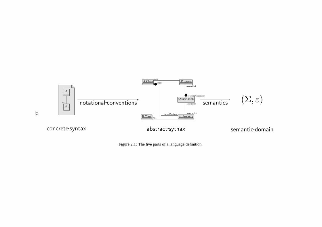
UML is a language of diagrams for describing systems. The diagrams are thesyntax, and the systems are the semantic domain. The concrete syntax of textualartificial languages are often parsed into tree structures which are much easier toprocess than the linear text. These structures are called the abstract syntax. Simi-larly, UML has an abstract syntax which is used to transform models and generatecode. UML’s subtle twist is that the class of structures usedas its abstract syntaxis defined using a collection of UML diagrams4.
Figure 2.1 shows these aspects of the language, and their relationships. Onthe left we have the concrete syntax, which in the case of UML are its diagrams.
An example class diagram is shown inside a UMLnote , which we use as akind of diagrammatic quotation to indicate that we literally mean the diagram, notwhat it represents or denotes. The notational conventions determine what abstractsyntax isrepresentedby a given collection of diagrams. We call an expression ofUML’s abstract syntax amodel. The wordrepresentswill be used exclusively forthis relationship between concrete and abstract syntax, and should not be confusedwith semanticdenotation. So the object diagram in the centre should be read as theconfiguration of objects represented by the quoted class diagram on the left. Theright hand side shows the semantic domain, the things or situations or in this case,systems which the language talks about. When precise semantics are required,we describe this semantic domain mathematically. As we haveindicated, systemswhich evolve over time, are often described as a set of statesΣ and a binary evolu-tion relationε over these states.
The relation in UML between concrete diagrammatic syntax and the abstractsyntax it represents, is complicated enough to be a potential source of error. Pre-cisely defining this relationship could simplify the creation of graphical model ed-itors, and facilitate animations [EHHS00,§6] and reverse engineering. The defini-tion should clearly delineate concrete syntax, abstract syntax and semantics, and itshould also specify the relationships between these parts.We therefore require that
Criterion 2. A UML definition should unambiguously define
concrete syntax the diagrams and other notation
abstract syntax the UML models
notational conventions a unique model for each diagram collection
semantic domain the abstract systems which models “talk about”
semantics whether a given model is true of a given system
4The class diagrams of the “Abstract Syntax” sections of the definition are actually MOF dia-grams, and should be interpreted according to its definition. However, the relevant part of the MOFdefinition is the UML Infrastructure [Obj07a], which also defines these diagrams in UML. The sit-uation is changed considerably with UML 2.2 (issued after the thesis was written), since it gives“normative” status to an electronic version of the UML metamodel.
22
(Σ, ε)
A
B
A:Class :Property
:Association
ex:PropertyB:Class
concrete syntax abstract sytnax semantic domain
notational conventions semantics
ownedEnd
owningAssociation
type
class
ownedAttribute
type
memberEnd
associationex
Figure 2.1: The five parts of a language definition
23

To summarise this section: we have found that diagrams need not be part ofa defined artificial language, but UML diagrams are. Artificial languages do notalways need to be precisely defined. However, UML should be precisely defined.Definitions of artificial languages come in two parts: syntaxand semantics, but forUML the usually straight-forward notion of abstract syntaxneeds separate carefultreatment.
2.4 Semantics
The part of the UML definition which has attracted the most research attentionis its semantics, because it is very unclear. Even the word “semantics” seems tobe understood differently by different people. In this section, we investigate thenotion of semantics in general, and the task of defining semantics for UML inparticular. We begin by comparing semantic definition with the better understoodtask of syntax definition.
The syntax of textual languages can be defined using a Chomskygrammar, andin the case of computer languages, this is almost always doneusing Backus-NaurForm (BNF). Graphical language syntaxes can be specified in asimilar way, usinggraph grammars [BH02]. A separate grammar for the concrete syntax might not bethe best way for UML though. Alternatives have been suggested which integratethe concrete syntax into the metamodel [FB05].
Grammars give a completely precise definition of a language’s syntax, leav-ing no doubt as to whether a given construction is part of the language or not.This precision also facilitates the construction of syntactic tools such as the parsergenerator YACC. Comparable techniques and tools exist for the specification ofprogramming language semantics [Sch96], but no clear winning technique akinto BNF has emerged. English text is by far the most common formof semanticdefinition used. UML, although executable, is different to typical programminglanguages because its models should admit a wide range of possible implementa-tion systems rather than a single specific system. That is, a UML model typicallyunderspecifies the required system.
We must avoid the mistake pointed out in [HR04], of thinking that preciselydefined language can only make highly specific statements. Although the languagedefinition leaves no doubt about whether a semantic entity satisfies a given speci-fication, the specification can never the less admit a wide range of possibilities. Aspecification such as “a truck with at least 6 wheels” can precisely define a verybroad range of vehicles. Using a precisely defined language does not necessarilycommit you to over-specification.
Many would argue that UML has no semantics [HR04, HS05], despite the nu-merous subheadings with that title in the documents which define the language[Obj06a, Obj07a, Obj07c, Obj06b]. Bran Selic [Sel04] counters these claims bycollecting and summarising the scattered material on semantics from the main offi-cial document of the time [Obj05] (which was in draft form when Selic used it). He
24

also encourages theoreticians to study ways of making the semantics more precise.The only real disagreement here is over the usage of the word “semantics.”
This is the topic of Harel and Rumpe’s excellent article [HR04], and their positionis that “semantics” is a mathematical term:
Regardless of the exposition’s degree of formality, the semanticmappingM : L // S must be a rigorously defined function fromthe language’s syntaxL to its semantic domainS. Needless to say, anadequate semantic mapping for the full UML does not exist.
It is interesting to note these authors implicit distinction between formality andrigour. Ordinary mathematics for example is rigorous, without being formal inthe logicians sense. UML is clearly informal, but Harel and Rumpe imply thatthis does not excuse it from rigour in defining its semantic mapping. They are notprepared to contemplate an approximate semantics, which they would probablysee as analogous to being a bit pregnant. Selic on the other hand recognises theneed for greater precision, but sees the existing definitionas at least good enoughto qualify as providing a “semantics”.
There are at least two more ways in which the word “semantics”is used. “De-velopers tend to use the word ‘semantics’ when they talk about the behaviour of asystem they develop” [KER99]. The connection between a UML model elementand the real world things it represents is also sometimes called semantics [EW01].Both of these usages refer to a direct connection between syntax and the real world.As we discussed in Section 2.1, this representation should be seen in two steps: themodel element denotes some mathematical entity in the semantic domain, and thisin turn represents something in the real world. The first stepis accomplished bythe language definition, the second by the model authors description of her modelelement.
Selic is not talking about either of these things. He means basically the samething as Harel and Rumpe when he talks about “semantics”, butlike the UMLdefinition itself, does not see the need for mathematical rigour.
It is important to note that the current description is not a com-pletely formal specification of the language because to do sowouldhave added significant complexity without clear benefit.
The structure of the language is nevertheless given a precise spec-ification, which is required for tool interoperability. Thedetailed se-mantics are described using natural language, although in apreciseway so they can easily be understood. Currently, the semantics are notconsidered essential for the development of tools; however, this willprobably change in the future. [Obj07a,§8]
This quote sets the scene for our investigation. It notes that some degree ofprecision is required to fulfil UML’s mission. It claims, with a little hesitation, that
25

this has been achieved without the use of rigorous mathematics. We will argue thatthere is a need for improvements, which we will identify.
Avoiding possible disagreements about whether or not a given system satisfiesa model is enough to motivate the semantic parts of Criterion2. Model driven de-velopment raises other questions whose answer depends on well defined semantics.
Since the abstract syntax of UML is defined by a UML metamodel,we actuallyrequire a subset of the semantics to even know whether an alleged model actuallyis a well-formed model. In Chapter 3 we look to the definition document to deter-mine the semantics of this fragment of the language so that wecan begin to workprecisely with UML’s abstract syntax.
We need it to be clear whether or not a given model is consistent. That is,can some system satisfy this model? When we have separately modelled distinctaspects of an envisaged system, we need a system which satisfies all of the aspectmodels. Model consistency includes: preservation of association multiplicities andother invariants; satisfaction of pre-post-condition contracts by object behaviours;satisfaction of use-case contracts by a model; safety properties (bad things can nothappen) and liveness properties (system does not get stuck). Chapter 5 will test theability of the current definition to decide model consistency, by examining a small,apparently inconsistent model.
If a model is made more concrete as a project progresses, we may wish to de-termine whether the more concrete model is a refinement of themore abstract one.Indeed, we may wish to establish once and for all that a certain model transforma-tion always produces a refinement of its input model. We tentatively call such amodel transformationsound. Refinement and soundness have various mathemati-cal definitions, but this is not the place to make these choices. Note however that itis not enough to say that one model is a refinement when it adds some detail, be-cause we probably want to consider model transformations like the famous class todatabase schema example [BRST05] to be a kind of refinement. This transforma-tion fundamentally restructures the input model rather than simply adding detailsto it.
The idea of transformation soundness might be of greater practical importancein model driven development than in traditional programming. High level lan-guage compilers, especially those used for production systems, are usually verymature, widely used and thoroughly tested. With model driven development, thesituation is different however, partly because the execution semantics of the mod-elling language can be highly nondeterministic. In an MDD process, translationfrom model to code might be achieved by a long chain of model transformations[MM03]. Some of these might be widely used and trusted, but others might be“one-offs,” created especially for the project at hand. Automatic verification ofsuch transformations could provide more confidence more cheaply than testing thetransformations.
The ability to establish the soundness of model transformations would enablerapid development and modification of trusted systems. If the model compiler hasalready been shown sound, and a proof of the required properties exists for the input
26
model, re-certifying a modified system would only require modifying the existingproof for the changes made to the model. Just as a model is easier to modify than alow level implementation, the proof about the model would beeasier to adapt thana proof about the implementation code.
We not only want these semantic questions to have definite answers, but wewould also appreciate any tool support in finding these answers.
Criterion 3. A UML definition should settle the following questions:
model consistencyis there a system which satisfies all these models?
model refinement is this model a refinement of that one?
transformation soundnessdoes output model always refine input?
The definition should also support maximally automatic tools to help determine theanswers to these questions.
It is important to note that, although the definition of UML ought to settle thequestion of whether a given model transformation is sound, not all useful transfor-mations are sound in this sense. For example, models can be used to generate tests,which are certainly not a refinement of the model from which they are derived.Soundness is primarily required for the chain of transformations which producesan implementation from the system model(s).
2.5 Metamodelling and Reflection
UML 2.1 is not defined in the way artificial language experts normally do business.How then is it defined? In this section and the next, we will take a brief look atthe official definition of UML [Obj07c], which we will sometimes refer to asthedefinition.
The long and complicated story that is UML’s definition begins with anotherdocument, called the “Infrastructure Specification” [Obj07a]. This gives a UMLmodel called the “Infrastructure Library,” which “contains all the metaclasses re-quired to define itself” [Obj07a,§7.2.8]. The Meta Object Facility (MOF) [Obj06a]builds on the infrastructure library to create a metamodelling language used to de-fine UML in [Obj07c]. This definition of UML proper begins by including theinfrastructure library.
The technique, of using a modelling language to define a modelling languageis calledmetamodelling.
Metamodelling need not be circular. One can give an independent definitionof the syntax and semantics of a modelling language, which wecall the metamod-elling language. Call the syntactic entities of this language “metamodels.” Themetamodelling language semantics specify a set of instances for each metamodel.One then nominates a metamodel as the definition of the abstract syntax of a newlanguage, which means that the abstract models of the new modelling language
27
are the instances of the nominated metamodel. To complete the definition of themodelling language, as we saw in Section 2.3, we would then need to specify thenotational conventions by which concrete diagrams (or whatever) are interpretedinto the abstract syntax, and we must provide a definition of its semantic domainand a semantic mapping from the abstract syntax into that domain.
The UML definition describes its usage of metamodelling as metacircular [Obj07a,§8.1], because it uses a UML subset to define UML. Without an independent defini-tion of the metamodelling language though, the “meta” seemslike an unwarrantedeuphemism. In the present work, we follow a bootstrapping process which avoidsthe circularity. We will begin in Chapter 3 by proposing a semantic domain, andthen very directly interpreting object diagrams in this domain in Section 3.2. Theobject diagrams will then be used to discuss pieces of abstract syntax and theirsemantic mappings. Finally, in Section 3.6, a second interpretation of object dia-grams will be made, in which we first find the abstract syntax represented by thediagram, and then define its semantic mapping. We justify theprocess by showingthat this second view of object diagrams is compatible with the first.
There are no dynamic elements in the fragment of UML that is used in thedefinition of UML, so we do not need to consider the evolution relation over systemstates at this stage. It is enough to clearly define when a given system state is aninstance of one of these static models.
A distinction is sometimes drawn between “runtime semantics” and “repositorysemantics” [Obj07c,§6.3]. The distinction seems to be stronger than the runtimebeing an extension of the repository version. This strikes us as a bad idea. InSection 2.2 we noted that uniformity is a significant aid to understanding. Themain advantage of using a fragment of UML to define UML is that there is less tolearn that way, but if the semantics are different at different levels, this advantageis lost. Indeed, it is more confusing than having a completely distinct language ateach level. Tool and transformation reuse between metamodel and model levelsalso depends on this uniformity. Therefore, despite there being support in parts ofthe definition for distinct semantics, we shall aim for a run-time semantics whichextends and includes the repository semantics.
As a result of this, the abstract syntax of the language is in its semantic domain.That is, each model is also a system state.
Having the syntax inside the semantic domain is also required in order to makesense of one of UML’s notions of instantiation. Consider a model with a classCand an instance specification: C. Although it would be redundant in this situation,we add an≪instanceOf ≫ arrow to the model, joining the instance specificationto the class. Assume for now that semantic mappings take instance specificationsto objects, and the classes to a sets of objects. The situation then can be depictedas shown in Figure 2.2.
Ignoring theinstanceOfTypearrow for a moment, we have a neat separationbetween syntax on the top line, and semantics on the bottom. So we see that the≪instanceOf ≫ notation in a UML diagram corresponds to “element of” (∈) inthe system state.
28

c C∈
//
:C
c
i
��
:C C≪instanceOf ≫ // C
C
i
��c
C
instanceOfTypellllllllll
66llllllllll
Figure 2.2: Semantics of Instantiation
The operationinstanceOfType, defined in MOF for the metaclass Element, “re-turns true if this element is an instance of the specified Class. . . ” [Obj06a,§13.3].The arrow in Figure 2.2 marked with this name, indicates an Element, Class pairwhere the operation returns true. The objectc is an instance of the classC. Theparameters of this operation include a model element and an element from the“current” system state instantiating that model. Thus the context in which this op-eration is called includes not only the run-time objects of the system state, but themodel as well. Another example of this kind is the OCL operation oclIsTypeOf[Obj06b,§7.5.9].
Systems in which objects can provide meta-data to describe themselves aresometimes called “reflective” [EN07, Chapter 1]. We have argued that UML shouldbe reflective in this sense. However, many different usages of “reflective” are inuse in the computing literature [DM95], often to do with a program’s ability tomodify itself. We only use “reflective” to mean “self-describing”, or requiringself-description.
In order to define the semantics of reflective notions such asinstanceOfTypeand oclIsTypeOf, we not only require the syntax to be in the semantic domain,we actually need each syntactic model to be present in every system state whichsatisfies it. In Section 5.3 we will see how this works for the dynamic parts ofUML.
We summarise our findings in the following criterion.
Criterion 4. The definition of UML should satisfy
unity runtime semantics extends repository semantics
reflection model contained in each of its instances
2.6 Semantic Variation Points
The UML definition contains a great number of “semantic variation points.” Theseare places where the semantics are explicitly undefined, or where a range of pos-sibilities are allowed. Chapter 18 of [Obj07c] describes the profiles mechanism ofUML, which allows subsets and extensions of UML to be defined.Model drivendevelopment may also call for domain specific languages which can interoperatewith UML models. Finally, UML 2.1.2 is only the latest of manyrevisions of
29
the language, and will not be the last. For all these reasons,we require semanticswhich areflexible.
We need the ability to switch between the options allowed by the semanticvariation points. The syntactic extensions defined in a profile will require a cor-responding semantic definition, compatible with the semantics of the UML subsetbeing extended. We will want to interpret the domain specificlanguages as makingstatements about the same class of systems that UML talks about. Let us assume,optimistically, that UML 3.0 will be published with mathematically precise yetreadily understandable semantics. When UML 3.1 and UML 4.0 are introduced,we will want to know what to do to obtain models in the new language which areequivalent to our expensively produced UML 3.0 models. We may also wish toupdate, perhaps automatically, formal proofs associated with these models. If thesemantics of the later versions are expressed in the same broad scheme, this willbe much more feasible.
Criterion 5. The definition of UML must enable the language to be adapted andextended. In particular, it requires a “semantic envelope”[Sel04] which enablesprecise treatment of:
semantic variation points
profiles
domain specific languagesinteroperable with UML
later versions of UML
2.7 The UML Definition Evaluated
Having established the properties that a definition of UML ought to have, we turnnow to the existing definition and ask, is it any good? In Chapter 5 we will lookclosely at the semantic aspects of this definition, and thus evaluate it with respectto Criterion 3. For now we take a broad, “external” view, evaluating the criteriathat do not depend on the specific details.
We begin with a perfect score on Criterion 0, since no definition can be morefaithful to the current definition than the current definition.
UML does not fulfil Criterion 1 so well as we could hope, because users arenot currently able to easily reach agreement about the meaning of a model.
. . . many people are confused about what these [UML] concepts. . . really mean and how to understand and use them [HR04]
Developers can waste considerable time resolving disputesoverusage and interpretation of notation. [BF98]
30
We have had similar experiences when attempting to extract the precise meaningof a diagram from groups of experienced UML practitioners: diverse interpreta-tions each received vigorous support. Debate continues at the OMG over funda-mental matters such as the semantics of associations and their ends [Obj, Issue#5977][Mil06]. It seems fair to conclude that there is not widespread agreementabout the meaning of UML models.
In order to enable agreement, as required by Criterion 1, a language ought tobe easy to understand. Implicit in many discussions of UML isthe argument thatthe language is visual, therefore it is easy to understand. This is an empirical claimthat should be verified experimentally. Nor does it follow that because UML hasemerged as a consensus incorporating the most useful features from many alterna-tives, that it is therefore maximally understandable. Thisalso requires empiricaltesting, and in fact there is some evidence against it [RBD05].
Criterion 2 can be summarised by saying that any proposed “definition” ofUML should actually define it. Debates on whether or not a given diagram is a cor-rect UML diagram, whether a system satisfies a given model andso on, should beeasily resolved by referring to the definition. Indeed, if the definition was clear andunderstandable, these debates would seldom occur. That is to say, satisfying Crite-rion 1 on enabling agreement, is probably our best indication of whether Criterion2 has been met. We must therefore conclude that the definitionis also lacking inthis respect.
It is not valid to infer from this that the definition lacks precision, because thelack of agreement could be the result of the definition being difficult to understand.This would be unfortunate, since it explicitly strives for understandability, even atthe cost of some precision [Obj07a,§8] (quoted on Page 25). To us, it seems moreplausible that the definition is neither precise nor understandable.
Turning to Criterion 3, one could hardly hope to settle questions of model con-sistency, refinement and transformation soundness withouttrue definitions of therelevant concepts. It should not surprise us then that Stephen Mellor finds a lack ofsupport for model consistency testing in the current definition [HS05]. He claimsthat the definition fails to detect the apparent inconsistency of his small examplemodel. In Chapter 5 we check Mellor’s claim, and find that, given a list of char-itable assumptions, the definition does in fact classify themodel as inconsistent.However, this effort cost us a great deal of time and trouble,and Mellor could beforgiven for giving up earlier than we did. It is not enough todefine consistency,the definition must also be usable.
Criterion 4, on reflection, is really a detail of Criterion 0,since it records whatis entailed by the definition. It is hard to say whether UML’s notions of reflectionreally work without trying to express them in a rigorous system. Although com-putational reflection is a huge area of study involving many subtleties [DM95], therequirements we have given in Criterion 4 do not seem so demanding.
Criterion 5 on flexibility, is only challenging for a rigorous definition. “Se-mantic variation points” offer perfect flexibility. Interpretation of the metamodeldiagrams by object-oriented folk-law is sufficient for current tools, which only ma-
31
nipulate the syntax. Without adequate support for the othercriteria though, thesebenefits are of little use.
The current definition of UML therefore does not rate very highly against ourcriteria. The remainder of the present work will aim to extract the essence of thelanguage and reformulate it clearly and precisely.
2.8 Conclusion
We have found six criteria for evaluating proposed definitions of UML. Brieflysummarised, they are as follows.
0. faithful to existing UML definition
1. understandableand implementable (supports agreement and tools)
2. definesconcrete syntax // abstract syntax // semantic domain
3. clarifies ideas: model consistency, model refinement, transformation sound-ness
4. reflective - objects can access their classes
5. flexible to support profiles and variations
The quote from the UML definition on Page 25 argues that a mathematical ap-proach involves too much work, and is not necessary to get thejob done. Whetheror not Greek letters and other fancy symbols are employed, precise definitionsof abstract ideasare mathematical. If we choose to ignore the accumulated wis-dom of the mathematical discipline, and define things our ownway, we committhe same error as “hackers” who refuse to follow establishedsoftware engineeringpractice. Like the hackers, we are likely to get ourselves into the kind of troublethat the experts know how to avoid. One simply does not find disagreements aboutthe meaning of definitions in mathematics, but after more than 10 years even thebasics of UML are still in dispute.
Are mathematical descriptions necessarily more precise than those in English?It is possible to make precise definitions in English, after all, mathematical con-cepts are defined in terms of other mathematical concepts which ultimately aredefined using English. Precision in English is difficult however: students askedto translate English statements into formal logic often findmany distinct plausibleinterpretations.
To avoid these situations, mathematical definitions are almost always built us-ing other mathematical definitions: so that the “foundation” can be as small aspossible, thus reducing the risk of ambiguity. As is well known, almost all ofmathematics can be defined within set theory, which uses onlythe logical concepts“and”, “not”, “all”, and “equals”, and the extra-logical notion of set membership:“is in”.
32

We have found that UML is a tool for working with ideas, and that the definitionof UML needs to be precise and understandable. To achieve this, we must discoverbasic notions that can be reused and built on throughout the language. We believethat such notions are there to be found, even if they are not explicitly known by thelanguage designers. In the following chapter, we uncover a powerful mathematicalconcept hidden in the UML metamodel. This will form the basisof a proposedsolution to the UML definition problem.
33
Chapter 3
Semantic Preliminaries
The UML definition problem was introduced in Chapter 1, and weanalysed it inChapter 2. Having made it clear what we are trying to do, it is time to get on withit. This chapter begins our study of the Unified Modelling Language itself, throughits current definition [Obj07c]. The aim is to establish enough of the semanticsto work with the abstract syntax. In other words, we want to find the “repositorysemantics”.
In Chapter 5, we will study in detail the syntax and semanticsof a tiny exam-ple UML model. We will begin with the concrete syntax: a collection of UMLdiagrams. This concrete syntax must be parsed into abstractsyntax, because thedefinition describes semantics for this abstract form of model rather than giving se-mantics directly in terms of the diagrams. The abstract syntax that we will obtainis an instance of the UML metamodel, which is in turn given by UML class andpackage diagrams. Therefore, before we can obtain the abstract syntax which theexample diagrams represent, we first require semantics for the fragment of UMLused to write the metamodel. This repository semantics should be a subset of thefull semantic definition of the language, as we determined inChapter 2 Criterion 4.
Needing the semantics of a language before we can define its syntax mightseem nonsensical, disconcerting or at least amusing to readers familiar with tradi-tional formal languages. As we shall see in Chapter 7, many attempts to formaliseUML ignore the metamodelling approach of the existing definition, and begin in-stead with a grammar to define the syntax. We consider this to be an undesirableand unnecessary deviation from the existing definition. Metamodelling has theadvantage of allowing the reuse of tools, techniques and understanding for bothmodelling and language design. After all, these two tasks are essentially the same,but at different levels of generality.
This chapter therefore develops a rigorous but faithful account of most of themetamodelling required to define UML. A few items are deferred to Chapter 4. Themetamodel makes heavy use of association end annotations such as{union} and{subsetsx}. Chapter 4 treats the difficulties of these annotations, andalso developsa proper account of generalisation and the evaluation of attributes and association
34
ends.The first section of the current chapter extracts an outline of UML’s semantic
domain from the current definition. We examine the core of theUML metamodeland consider its intuitive interpretation. We find deep parallels with a particularmathematical approach to graphs, and argue that UML’s metamodel, models andsystem states are all graphs. We then study object diagrams,which offer an idealstarting point for our semantic investigations because they show quite directly whatthey are intended to denote. The following section introduces class diagrams andmodels. We see that a system snapshot’s instantiation of a model takes the formof a graph homomorphism. This idea is well known in the literature, but we solvesome difficulties and add flexibility by introducing interpretation functors. Section3.4 applies our findings to a tiny, core fragment of the metamodel, showing thatit is self-instantiating in a non-trivial way. Reflection iscalled for by Chapter 2’sCriterion 4, and this is addressed in Section 3.5. Here, the metamodel is includedin the model, the model in the system state, and instantiation is made explicit usingspecially labelled graph edges. Finally, the naive view of object diagrams takeninitially is replaced by a treatment consistent with the other diagrams: they areseen as representing elements of a model rather than directly denoting a systemstate. This change is justified by showing that the later viewis a generalisation ofthe first.
3.1 The Semantic Domain
What are the general properties of the systems that UML models talk about? Anoverview is given in the definition [Obj07c,§6.3], from which we have extractedthe following points. A system is a set of objects, connectedby links. The objectshave named values attached to them, which are calledattributes. Objects can actand interact and evolve over time. All the action in the system is carried out byobjects, and the system evolves in discrete steps. Objects can act in parallel, andthere can be several possible ways for the system to evolve. That is, systems de-scribed by UML can benondeterministic. Objects can be created and destroyed, ascan the links that join them. Objects have an identity, so we can trace an individualobject’s progress in the evolution of a system containing many objects. Two ob-jects are distinguishable even if all their attribute values are equal. Together withLeibniz law, this implies that each object has (or is) a unique object identifier.
To summarise, at any given instant, the system consists of a bunch of linkedobjects, which we will call asystem state. A systemtherefore is a set of thesesystem states, with a binaryevolutionrelation, which tells us for each state, whatcan happen next.
A system state consists of objects which have named connections to one an-other and to other values. This kind of structure is studied in mathematics underthe name “graph”. In fact a bewildering array of slightly different structures arecalled “graph”, so we should specify that we mean edge-labelled directed multi-
35

Figure 3.1: Diagrammatic definition of agraph from [LS86]
Propertyname: String
Classifierclassifier
1type
1
Figure 3.2: A suggestive fragment of the UML 2 metamodel
graphs. Each edge joins two nodes in a particular direction,and has a label. Insome kinds of graph, it is not possible for two different edges to connect the samepair of nodes, which is why we call our variety a “multi-graph”. Although it is notmade explicit, UML’s definition strongly suggests that system states are graphs.
Graphs are sometimes defined using a diagram, such as the one shown in Figure3.1 taken from [LS86]. Technically, this diagram shows a small category, and agraph is defined to be afunctor from this category into the category of sets. So theballoons become sets and the arrows become functions. Compare this diagram withthe core of the UML metamodel, shown in Figure 3.2. The similarity between thesetwo diagrams is the key to the following argument that UML system states, modelsand the metamodel are all graphs. Although it uses some technical definitions thatare introduced later, it seems important to make a case for graphs before proceedingtoo far with them.
By adding aLabelsobject to the diagram of 3.1, and an arrow into it fromArrows, we have a category theoretic definition of edge-labelled multi-graphs. Theresulting diagram can be seen as a category with 3 objects, oras a graph with 3nodes. We will refer to them both asG, sometimes allowing the context to deter-mine whether it is the graph or the category we are talking about. The metamodelfragment of Figure 3.2 is clearly isomorphic toG.
Although we claim that different people have different understandings of UML,the meaning of the small simple fragment used in the model of Figure 3.2 is fairly
36
clear. An instance of this model consists of a set of Properties and a set of Classi-fiers. Each Property has anamewhich is a string, and is associated with 2 Classi-fiers (possibly the same) one called itsclassifierthe other itstype. Since the mul-tiplicities are 1 on the attribute and named association ends, these things are func-tionsname: Property // String, andclassifier, type : Property // Classifier.
But this is exactly the way the category diagram of Figure 3.1is interpretedby a functor to yield a graph. That is, an instance of the metamodel fragment inFigure 3.2 is a functor from the diagram as a category, into the category of setsand functions. Thus, the same diagram, interpreted in the same way gives us bothgraphs and models. Therefore models are graphs.
However, on this view, the metamodel is a category. This is not satisfactory,because the metamodel is a model, and therefore should also be a graph. Further-more, the models themselves should have instances. We therefore invoke a littletheory to turn the metamodel as a category into another graph, and replace thefunctors with graph homomorphisms, which are defined in Section 3.3, Definition3 (on Page 45). In that Section we shall see that an object diagram’s instantiationof its class diagram is just like a graph homomorphism.
A terminal object in a category is one which has a unique arrow into it fromevery object. There is a terminal graph, and for any graph we can find the uniquehomomorphism into it by a kind of inversion of its functor.
Proposition 1. The category of graphs has a terminal object.
Proof. Let g be a graph. Define!g by taking each node ofg to the formal symbolnode, each edge ofg to the formal symboledgeand each label ofg to the formalsymbol label. Let {node}, {edge} and {label} be the nodes, edges and labelsrespectively of a new graph⊤, whose source and target functions both takeedgetonodeand whose label function takesedgeto label. Any homomorphismg // ⊤is equal to!g.
Like all graphs, the terminal graph⊤ is a functor fromG into Set. Its pecu-liarity is that it takes all three ofG’s objects to singletons. This does not convertthe categoryG into the graphG, because the resulting graph has only one nodeinstead of 3. But the graphG is strange in that two of its nodes “represent” an edgeand a label respectively. Each of the edges “represents” an element of thesource,targetor label functions. Indeed, any graph could be converted into another graphin this way. The edges and labels become nodes, and thesource, target and labelfunctions become sets of edges. We call this encoding of graphs to graphsα (for“algebraisation”), and its inverseγ.
Note that this inverse relationship betweenα andγ only works in one direction.If we attempt to useγ to “decode” a graph that has not been “encoded” byα, thenit will probably have edge labels other thansource, targetandlabel, which are theonly ones thatγ “understands”. That isγ(α(g)) = g, but in general,α(γ(g)) 6= g.However, sinceG = α(⊤), we have
α(γ(G)) = α(γ(α(⊤))) = α(⊤) = G
37
.These two graph manipulations play a vital role in our understanding instanti-
ation in UML. We defineγ more carefully in the pages to come, and Proposition 2(on Page 47) shows thatγ is a functor. We expect thatα is also a functor. Indeed,the pair may be adjoint [Mac98,§IV], but we have not investigated this.
We have shown that there is a unique homomorphism!g : g // ⊤ = γ(G)for each graphg. We initially showed that the instances of the metamodel weregraphs: functors from the metamodel into Set. This was unacceptable because themetamodel should be a graph, and its instances should also have instances. Butgis a graph if and only if there is a homomorphismg // γ(G).
We can therefore preserve our intuitive interpretation of the metamodel, havethe metamodel be a model, and extend instantiation to systemstates by defininginstantiation in the following way:s instantiatesm whenever a homomorphisms // γ(m) exists. We will see in Section 3.3 that this notion of instantiationworks for system states instantiating models, and in Section 3.4, that the meta-model instantiates itself in this way. These considerations strongly support theidea that UML system states, models and the metamodel are allgraphs, and thatinstantiations are homomorphisms into our decoding functor γ.
We must remain cautious about our hypothesis that system states are graphshowever. Firstly, the diagram of 3.2 is notquitea fragment of the UML metamodel.The typeof a Property is actually a Type rather than a Classifier. However Type isan abstract class, and Classifier is its only subclass, so there are no values belongingto a Type but not to a Classifier. The other association in our diagram,classifierdoes not actually appear in the text of [Obj07c,§7.3.44], but it does appear inFigure 7.9 [Obj07c, Page 29], and is referred to in Figure 7.12 [Obj07c, Page 32].An OMG UML “issue” [Obj, #10001] suggests that it be added, noting that “anumber of the OCL expressions [in [Obj07c]] are currently written (incorrectly)with this assumption.” The second reason for caution about the graph hypothesisis that there is a lot more to the metamodel than this tiny fragment. We mustgive an account of all of it, not just some little bit that reminds us of some sexymathematics. Despite these reasons for caution, we think the graph approach willwork, and we will keep it as a working hypothesis.
3.2 Object Diagrams and System States
UML has a kind of diagram for showing objects and links, called an object dia-gram. An example object diagram is shown in Figure 3.3. This section introduces asomewhat naive interpretation of object diagrams that we will ultimately replace inSection 3.6. Here, we ignore the fact that object diagrams, like all UML diagrams,actually represent pieces of abstract syntax which make up amodel. Instead, wesee them as a notation for graphs.
In the previous section, we considered graphs as functors from a certain di-agram into the category of Sets. This facilitated our argument for the parallels
38

a:Apple
grams = 150b:Basket
contains in
Figure 3.3: An object diagram
between UML and graphs, but it is an unnecessarily abstract way to define them.
Definition 1. A directed multi-graphis a pair of sets called thenodesand theedges, and two functions: source, target : edges // nodes. Anedge-labelleddi-rected multi-graph has an additional set, thelabels, and function label: edges //
labels.
Since the only graphs we are interested in are directed multi-graphs, we willsometimes refer to these structures simply as graphs. When the context makes itclear, even edge-labelled directed multi-graphs will sometimes be called graphs orlabelled graphs.
Nodes are sometimes called vertices or objects, and the edges sometimes calledarrows. We will avoid the word “object” for nodes, as we already have two distinctuses for it in object oriented programming and category theory. However, someof our graph nodes will indeed be (object oriented) objects.We consider objectidentifiers and values to be nodes, and these nodes are connected by directed edgeslabelled by names. So, an objecta with an attributegrams = 150 will be thefollowing graph fragment.
agrams // 150
Object diagrams are easy to understand, because they very directly show thestate of a collection of objects and links: each object is shown as an icon containingthe object’s attributes as name value pairs, and each link isshown as a line joininga pair of object icons. The ends of links can show pieces of text. By convention,these association end “names” are verb phrases which allow us to make sentencesabout the objects at either end. For example in Figure 3.3, weread that the appleis in the basket, and the basketcontainsthe apple. In fact, links can have morethan 2 ends, but we do not yet need to consider such links because the metamodelcontains only binary associations.
What is the graph that our object diagram denotes? It will have four nodes, onefor each of the objects, one for the link and one for the value 150. There will be anedge labelledgramsfrom objecta to 150. An arrow intoa will be labelledcontainsand one intob will be labelledin. The sources of these two arrows is somethingwe must investigate.
Association is a specialisation of Classifier in the UML metamodel, and linksare instances of Associations. Each Association has 2 or more ends, where it con-nects to a Class. Each end is described in the model by a Property. For binary
39

150 oo gramsa oo contains
ℓin // b
Figure 3.4: If both association ends are owned by the association (AA), then this isthe system state denoted by the object diagram in Figure 3.3
a150gramsoo ba
contains
ii ℓ b%%
Figure 3.5: If in:Property is owned by the Association, butcontains:Property isowned by Basket (AC), then this is the system state denoted bythe object diagramin Figure 3.3
associations, each Property can belong to the Class or to theAssociation, givingus 3 kinds of case: both ends owned by the Classes, both ends owned by the As-sociation, and the mixed case. For Associations with 3 or more ends, all the endProperties must be owned by the Association. Each of these possible cases are ex-plained by the general principle we have already used for Classes and Attributes:each Property describes a set of edges, each of which comes from an instance ofthe Propertiesclassifier, and goes to an instance of the Propertiestype.
However, we are considering the object diagram in isolation, without regard toany particular class model. Our only option then is to consider any links shown inthe diagram to be ambiguous, and look separately at each possible case. In Figure3.4, both ends are owned by the association, in Figure 3.5 oneend is owned by anend Class and one by the Association, and in Figure 3.6 both Properties are ownedby the end Classes. There is of course a fourth case dual to themixed case ofFigure 3.5. We will use the abbreviations CC AC and AA for these interpretations,being acronyms for Class Class, Association Class and Association Associationrespectively.
The mixed cases, like in Figure 3.5 can only be legitimate interpretations ofclass diagrams in which explicit end ownership notations occur [Obj07c,§7.3.3].This small dot at the end of the association line is an innovation of UML 2.1. Whereit does not occur, either of the uniform (non-mixed) interpretations is acceptable.
This formulation of system state naturally caters for a strange possibility al-lowed by the UML definition. It is possible for an object to have two differently
a150gramsoo ba
contains
ii ℓℓa b
in
))
Figure 3.6: If each association end is owned by its Class (CC), then this is thesystem state denoted by the object diagram in Figure 3.3
40

:Order
quantity = 1quantity = ‘‘two’’
Figure 3.7: A surprising but legal object
typed values under the same name [Obj07c,§7.3.34], such as the example shownin Figure 3.7. Many formalisations of UML, including ours inChapter 6, treatProperties as typed functions from objects to values. To do this in such formali-sations, some trick would be required, like defining a union type. Other authors[RCA01] create a union typeValueof all possible values, and must explicitly for-malise the type restrictions on the attribute functions. Inour proposal, and manygraph transformation approaches, typing is achieved usinga type graph. In thegraph formulation, each of the two Properties would become an edge from theClass to the Property type in the dealgebraised type-graph.As a result, only prop-erly typed values for that attribute name would map homomorphically into it. Wesee no need for any additional typing system.
We have not yet accounted for the class names in Figure 3.3, that is Apple andBasket. Intuitively, the class names are telling us that these objects areinstancesof these classes. We have decided that the model should be present in the systemstate, so the graphs shown in Figures 3.4, 3.5 and 3.6 are not complete systemstates, because the model is missing. In the next section we will find the modelrepresented by a class diagram, which our object diagram “instantiates”. We willadd that model to the system state, and connect objectsa andb to their classes withspecial instantiation edges. There are intuitive restrictions about what can be aninstance of what, and we will capture these using the idea of agraph homomor-phism. In the following section we will continue up the metamodelling hierarchy,adding a self-instantiating metamodel.
We now have a tentative definition of system state, and a preliminary, tem-porary semantic mapping for object diagrams. Next we begin to take seriouslythe idea that diagrams representmodels, and thus study the notational conventions(Figure 2.1 on Page 23) for parsing class diagrams. Since models are system statesare graphs, and object diagrams are now established as a notation for graphs, wecan use object diagrams to display our models.
3.3 Class Diagrams and Models
Now we are ready to consider the most basic kind of class diagrams, and we beginto use the notion of amodel. We have already mentioned some (meta)classes fromthe metamodel: Association, Property and Class. The model will be a system statein which the (meta)objects belong to (meta)classes such as these. We will use
41
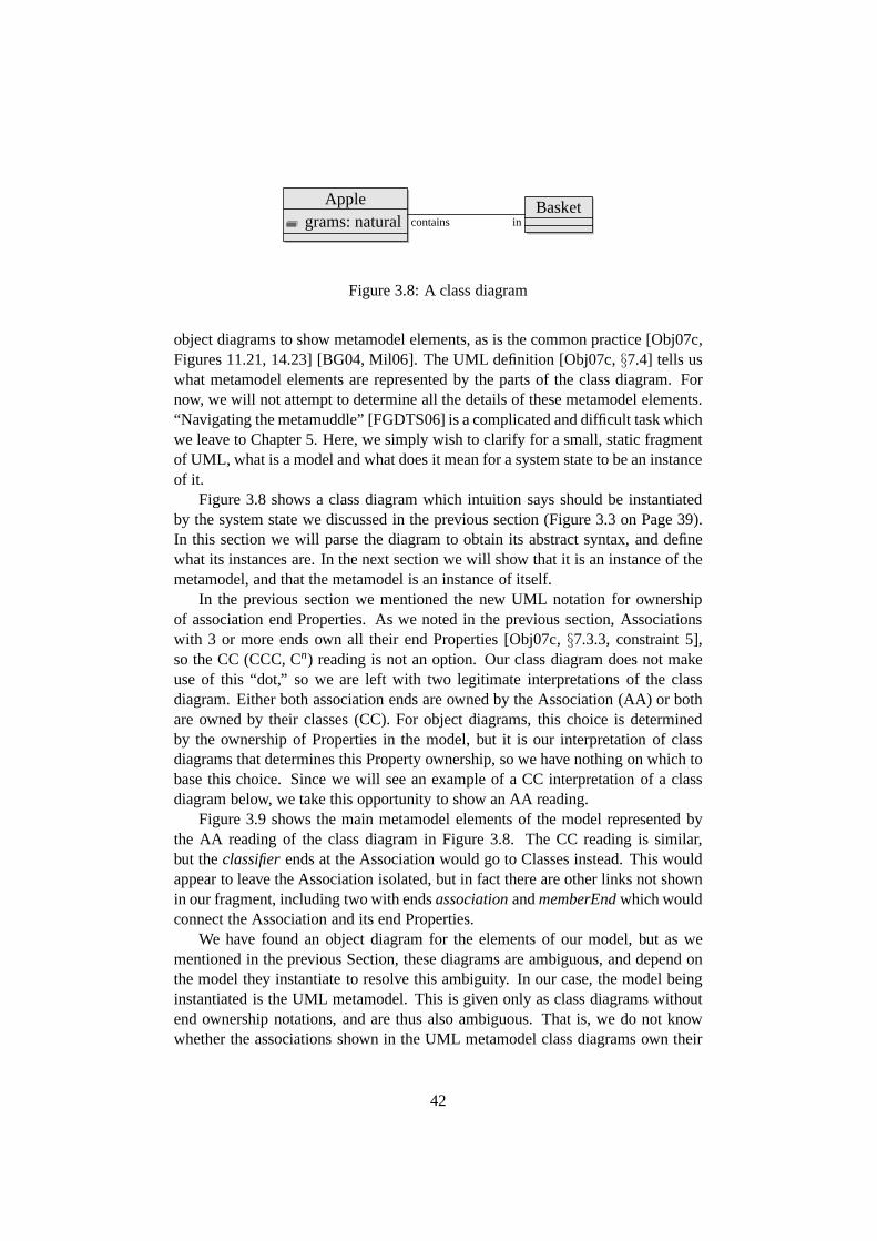
Applegrams: natural
Basketcontains in
Figure 3.8: A class diagram
object diagrams to show metamodel elements, as is the commonpractice [Obj07c,Figures 11.21, 14.23] [BG04, Mil06]. The UML definition [Obj07c,§7.4] tells uswhat metamodel elements are represented by the parts of the class diagram. Fornow, we will not attempt to determine all the details of thesemetamodel elements.“Navigating the metamuddle” [FGDTS06] is a complicated anddifficult task whichwe leave to Chapter 5. Here, we simply wish to clarify for a small, static fragmentof UML, what is a model and what does it mean for a system state to be an instanceof it.
Figure 3.8 shows a class diagram which intuition says shouldbe instantiatedby the system state we discussed in the previous section (Figure 3.3 on Page 39).In this section we will parse the diagram to obtain its abstract syntax, and definewhat its instances are. In the next section we will show that it is an instance of themetamodel, and that the metamodel is an instance of itself.
In the previous section we mentioned the new UML notation forownershipof association end Properties. As we noted in the previous section, Associationswith 3 or more ends own all their end Properties [Obj07c,§7.3.3, constraint 5],so the CC (CCC, Cn) reading is not an option. Our class diagram does not makeuse of this “dot,” so we are left with two legitimate interpretations of the classdiagram. Either both association ends are owned by the Association (AA) or bothare owned by their classes (CC). For object diagrams, this choice is determinedby the ownership of Properties in the model, but it is our interpretation of classdiagrams that determines this Property ownership, so we have nothing on which tobase this choice. Since we will see an example of a CC interpretation of a classdiagram below, we take this opportunity to show an AA reading.
Figure 3.9 shows the main metamodel elements of the model represented bythe AA reading of the class diagram in Figure 3.8. The CC reading is similar,but theclassifierends at the Association would go to Classes instead. This wouldappear to leave the Association isolated, but in fact there are other links not shownin our fragment, including two with endsassociationandmemberEndwhich wouldconnect the Association and its end Properties.
We have found an object diagram for the elements of our model,but as wementioned in the previous Section, these diagrams are ambiguous, and depend onthe model they instantiate to resolve this ambiguity. In ourcase, the model beinginstantiated is the UML metamodel. This is given only as class diagrams withoutend ownership notations, and are thus also ambiguous. That is, we do not knowwhether the associations shown in the UML metamodel class diagrams own their
42

in:Property
name = ‘‘in’’R1:Associationcontains:Property
name = ‘‘contains’’
Apple:Class Basket:Class
grams:Property
name = ‘‘grams’’
natural:DataType
classifierclassifier
type type
classifier
type
Figure 3.9: Metamodel elements of the class diagram (AA interpretation)
end Properties, or whether these Properties are owned by theend Classes. There isan electronic form of the metamodel, issued by the OMG in the proprietary formatof IBM’s Rational Rose tool. This would give an answer to the question, but notan authoritative one, since it lacks “normative” status1
The choice then seems to be ours to make, which is good, because the accountof instantiation as graph homomorphism that we wish to develop works much moresimply if we take a CC reading of the metamodel. This means we can very directlysee the the object diagram of Figure 3.9 as a labelled directed graph. The linknodes will be isolated, and each link shown in the object diagram will denote a pairof edges between the object nodes at its ends, in opposite directions. One of eachpair will have an arbitrary label, determined by our interpretation of the metamodeldiagrams. We will adopt the convention that the partner of anedge labelledx willbe labelledxInv, so for example the link betweengramsandnatural in Figure 3.9
will denote a pair of edgesgramstype // natural andnatural
typeInv // grams.An important difference between this model and the system state that we feel
should instantiate it, is that the Properties are nodes in the model, but edges in thesystem state. The definition seems to support this. “Property represents a declaredstate of one or more instances in terms of anamed relationship to a value or values”[Obj07c,§7.3.44, Description] (emphasis added). Graph treatments of UML-stylemodelling languages usually define instantiation as graph homomorphism, which
1Updated versions of these files, in the standard .xmi format became normative with UML 2.2[Obj09] in February 2009. These files confirm that the metamodel classes own their association ends,ie the CC reading is applied to the metamodel diagrams.
43

natural oo gramsApple oo contains R in // Basket
Figure 3.10: The object diagram of Figure 3.3 can be seen as analgebraic graphstructure, drawn in traditional form here. That is, this graph isγ′(s) (Definition 9),wheres is the system state denoted by the object diagram of Figure 3.3.
seems to capture the intuition well (eg [BH02], graph homomorphism is definedbelow). This means that the labelled edges that represent anobjects properties mustmap to similarly labelled edges in the type graph. Can we reconcile Properties asnodes with Properties as edges?
Another way of seeing Figure 3.9 is as the “algebraic” form ofa new graph.Recall that a graph is a set of a set of edges with source and target functions into aset of nodes, and a label function into a set of labels. The Properties in the graphof Figure 3.9 each have unique outgoing edges labelledtype, classifierandname.Thus the nodes that these arrows originate from become the edges of our newgraph. The nodes of the new graph are the destination nodes ofthe classifier andtype edges, and the labels the destination nodes of the name nodes. The resultinggraph is shown in the traditional graphical way in Figure 3.10.
The similarity between the graphs of Figures 3.4 (Page 40) and 3.10 is ob-vious. Indeed, there is an obvious label preserving graph homomorphism whichsends each object to the class that it should instantiate. Wetherefore propose to“interpret” the class model using “dealgebraisation”, to obtain a type graph whichdetermines the models instances.
Dealgebraisation turns out to be afunctor, an idea from category theory. Wediscuss the connections with category theory a little more after defining the graph-part of the interpretation functor in Definition 2. We then show it is a functor inProposition 2. The functor will be replaced in Definition 9 bya minor technicalvariant which we will callγ. The interim version we are about to introduce istherefore calledγ′. A couple of notational conventions will allow us to be moreconcise. When the context makes it clear which graph is beingdiscussed, we will
write e : x ℓ // y to abbreviatesource(e) = x & label(e) = ℓ & target(e) = y,
andx ℓ // y for (∃ e∈ edges)e : x ℓ // y.
Definition 2. Let g = (nodes,edges, labels, source, target, label) be a labelledgraph. Let edges′ be the nodes n∈ nodes where n has exactly one outgoingedge labelled “classifier”, exactly one labelled “type”, and exactly one labelled“name”b. Let
source′ = {(e′,n′) | e′ ∈ edges′ ∧ e′classifier // n′}
target′ = {(e′,n′) | e′ ∈ edges′ ∧ e′type // n′}
label′ = {(e′, ℓ′) | e′ ∈ edges′ ∧ e′ name // ℓ′}.
44
We complete the definition of a new labelled graph
γ′(g) = (nodes′,edges′, labels′, source′, target′, label′)
by setting
nodes′ = Range(source′) ∪ Range(target′) and
labels′ = Range(label′)
We have informally used the idea of graph homomorphism, which is a structurepreserving map from one graph into another. The idea is defined as follows.
Definition 3. Letg = (nodes,edges, source, target)
andg′ = (nodes′,edges′, source′, target′)
be graphs. Agraph homomorphismg // g′ consists of a pair of functions n:nodes // nodes′, e : edges // edges′ such that
n(source(x)) = source′(e(x))
n(target(x)) = target′(e(x))
for every x∈ edges.
As usual, if both components of a graph homomorphism are bijective (one toone onto) we call it a graphisomorphism. In this case, its inverse is also a graphhomomorphism.
Category theory is used heavily in the literature on graphs and graph trans-formations [EEPT06]. The work presented in this dissertation does not go deepenough to need this kind of machinery, but we relate it to the category theoreticsetting where we can, in the hope that it will facilitate future work. Readers unfa-miliar with category theory will not miss anything substantial. The standard workon category theory is [Mac98], and a gentle introduction forcomputer science is[Pie91].
A category is like an (unlabelled directed) graph, except that the edges (calledarrows) can be composed to form new arrows. Each node (calledan object) hasa special identity arrow, which when composed with another arrow, yields thatarrow unchanged. One example of a category has graphs as objects and graphhomomorphisms as arrows. Category, as a kind of mathematical structure, hasits own notion of homomorphism: a homomorphism between categories is calleda functor. There is also a notion ofnatural transformationbetween two parallelfunctors, that is, functors between the same pair of categories.
Graphs themselves may be defined as functors from the category • // // • tothe category of sets. When graphs are seen this way, graph homomorphisms arenatural transformations[Mac98,§I.4] between them.
45
Definition 3 does not mention graph labels. The following definition extends itto include a mapping of labels. Our apple in a basket example of homomorphismas instantiation motivates a stronger notion of labelled graph homomorphism. Inthat example, edges only map to edges with the same label.
Definition 4. Let
g = (nodes,edges, labels, source, target, label)
andg′ = (nodes′,edges′, labels′, source′, target′, label′)
be labelled graphs. Alabelled graph homomorphismis three functions n: nodes //
nodes′, e : edges // edges′ and l : labels // labels′ such that(n,e) is a graphhomomorphism, and
l(label(x)) = label′(e(x))
If l = idlabels, (and therefore labels⊆ labels′) we say(n,e, l) is label-preserving.
The inverse of a label preserving graph isomorphism is also alabel preservinggraph isomorphism.
We can now name some categories of graphs. The composite of two (labelpreserving) homomorphisms is also a (label preserving) homomorphism, and theidentify function over a labelled graph is a (label preserving) homomorphism. Wetherefore have two categories whose objects are labelled graphs. The one with allhomomorphisms will be calledGr, the subcategory whose arrows are label pre-serving graph homomorphisms we callLPG.
Definition 2 gives us a function from graphs to graphs. This will serve as theobject part of a functor, but a functorF must also take each arrowf : g // hto an arrowF(f ) : F(g) // F(h), and it must preserve the categories structure:its composition and identity arrows [Mac98,§I.3][Pie91, §2.1]. Since the edgesand nodes ofγ′(g) are all nodes ofg, we can obtain suitable arrow and node com-ponents forγ′(f ) by restricting the node component ofg. We write f↾A
for thefunction f restricted to the setA.
This will only work if the nodes ing that represent edges are mapped byf tonodes inh that also represent edges. The labelstype, classifierandnameplay aspecial role when we use a graph to represent another graph inalgebraic form. Theedges of the original graph become nodes with exactly one outgoing edge for eachof these labels, and this is howγ′ (Definition 2) recognises them. Any node whichhas these edges can only be mapped by a label preserving homomorphism to a nodethat also has them. However, there is no guarantee that this latter node has onlyone outgoing edge with each of these three labels. It might for example have twooutgoing edges labelledtype, and thus not be turned into an edge byγ′. Rather thanrestricting the homomorphisms to account for this, it seemsmore natural to restrictthe graphs to those that seem to make sense as algebraic representations of other
46

graphs. Some nodes will need to havetypeedges but noclassifierfor example, butwe want to exclude nodes that have all three, but have more than one edge with thesame label.
Definition 5. A graph node is tcn if it has exactly one outgoing node with each ofthe labels type, classifier and name. A graph is tcn if each node with outgoing type,classifier and name edges is tcn. We writeGrtcn andLPGtcn for the subcategoriesof Gr andLPG whose objects are tcn graphs.
Proposition 2. The functionγ′ : Graph // Graph of Definition 2 is the objectcomponent of a functorLPGtcn
// Grtcn.
Proof. Let g andh be tcn graphs andf : g // h a label preserving homomor-phism. Define the three components ofγ′(f ) as follows.
edges(γ′(f )) = nodes(f )↾edges(γ′ (g))
nodes(γ′(f )) = nodes(f )↾nodes(γ′ (g))
labels(γ′(f )) = nodes(f )↾labels(γ′ (g))
If e is an edgee : t n // c in γ′(g) then it is a node ing with outgoing edges
etype // t, e
classifier // c ande name // n. These are the only outgoing edges from
e with these labels. The three edges are mapped byf to edgesf (e)type // f (t),
f (e)classifier // f (c) andf (e) name // f (n) in h. Sinceh is tcn, these are the only
edges with these labels out off (e). That is,f mapstcnnodes totcnnodes.
Thereforef (e) is an edge inγ′(h). More specifically,f (e) : f (t)f (n) // f (c).
But f (e) = γ′(f )(e), so we have shown that the edge component ofγ′(f ) takesedges to edges. Each node inγ′(g) is analogous to the nodest andc, being at thefar end of atypeor classifieredge out of atcnnode. Sincef preservestcn, f (t) andf (c) will be nodes inγ′(h). But γ′(f )(x) = f (x) for γ′(g) nodesx, so,γ′(f ) takesnodes to nodes. Similarly, the labels ofγ′(g) map to labels ofγ′(h), because thetcn property and the labelnamepreserved byf . We have now shown thatγ′ takeslabel preserving homomorphisms to homomorphisms. It remains to show that itrespects composition and identity.
Let k also be atcn graph, andj : k // g a label preserving homomorphism.We now show thatγ′(f ◦ j) = γ′(f ) ◦ γ′(j). We have
edges(γ′(f ◦ j)) = nodes(f ◦ j)↾edges(γ′(k))
= nodes(f↾edges(γ′ (g))◦ j↾edges(γ′(k))
)
= nodes(f↾edges(γ′ (g))) ◦ nodes(j↾edges(γ′ (k))
)
47
since the node component ofj takesγ′(k) edges toγ′(g) edges. Similar reasoningapplies to the node and label components ofγ′(f ◦ j).
Finally, each component ofγ′(idg) is a subset of the node component ofidg,and thus the identity function over the nodes, edges and labels ofγ′(g) respectively.We therefore haveγ′(idg) = idγ′(g).
In what follows, we will find uses for graph interpretation functions other thanour dealgebraisation functionγ′, and so we make the following definition genericin this respect.
Definition 6. We say that a labelled graph s isanf -instance ofa labelled graph miff there is a label preserving graph homomorphism h: s // f (m).
This is a parametric semantics for graphs. Given an interpretation functionf ,we have a set of instances for each graph. The expressions // f (m) is a ratherdegenerate example of a style of diagram from category theory, called a commutingdiagram. Different parts of UML models are interpreted in different ways. Laterin this chapter, and more fully in Chapter 8, we will achieve this by using severalinterpretation functions in a commuting diagram. This kindof modular flexibilityis a good thing, because we aim to cater for UML’s “semantic variation points”.
We noted before that there is a label preserving homomorphism between ourexample system state and the interpreted model. With our definitions, this justifiesthe following statement of instantiation.
Proposition 3. The graph of Figure 3.4 (Page 40) is aγ′-instance of the graph ofFigure 3.10.
Thus as we would hope, the denotation of the object diagram inFigure 3.3(Page 39) is an instance of the denotation of the class diagram in Figure 3.8 (Page39).
The reader might wonder what is the point encoding a graph in algebraic form,as another graph. Why not just store the model in its dealgebraised form, andcall graph homomorphisms instantiations? This would be sufficient to define thesemantics of models by determining what its instances are. However, the modelsyntax must exist in a form that can be navigated by modellingand code generationtools. We see the nodes of our graphs as data values, and the edges as the meansof navigation through these values. For tools to process models, all the modelelements must be accessible. This includes the Properties which dealgebraisationturns into edges. Access must be via edge labels that are known in advance, whichin the algebraic form, are the association end names given inthe metamodel.
The direct, instantiation-as-homomorphism view would also fail to accountfor metamodels which are self-instantiating. Under that view, every model wouldbe self-instantiating, since the identity function over a graph is certainly a labelpreserving graph homomorphism. We will see in the next Section that the definitionwe have given does provide a non-trivial account of self-instantiation.
48
There would probably be uses for a weaker notion of instantiation, using la-belled graph homomorphism rather than label preserving ones. This would allowfor synonyms that may arise, for example as a result of different “viewpoints” beingmodelled by separate teams.
We come now to a point about UML that many find surprising. Objects caninstantiate more than one class. The first way this can happenis through general-isation. “Where a generalization relates a specific classifier to a general classifier,each instance of the specific classifier is also an instance ofthe general classifier.”[Obj07c,§7.3.20].
UML also allows an object to instantiate several different classes simulta-neously, regardless of their relationship in the specialisation hierarchy. The de-scription of InstanceSpecification and the reclassifyObjectAction makes this clear[Obj07c,§7.3.22,§11.3.39]. The definition’s explanation of GeneralizationSet alsodescribes cases of objects instantiating two or more classes. Several Generaliza-tions can be grouped using a GeneralizationSet [Obj07c,§7.3.21], which can bemarked{overlapping}. This mark in the diagram indicates that the Generaliza-tionSet attributeisDisjoint has the valuefalse, which is actually the default. Thedefinition gives an example. “Person could have two Generalization relationshipsinvolving two specific (and non-covering) Classifiers: Sales Person and Manager.This GeneralizationSet would not be disjoint because thereare instances of Personthat can be a Sales Person and a Manager” [Obj07c,§7.3.21]. This example makesit clear that one object can be an instance of two different classes, neither of whichspecialises the other.
The account of instantiation we have developed so far only allows an objectto instantiate a single Classifier. What we need is a type graph whose nodes areactually sets of nodes. Thus we define a power-graph construction that takes agraphg and yields a new graphP(g) (or 2g) which has sets ofg nodes as its nodes.For the edges, we put an edge from one set of nodes to another ifit goes from a
member of one to a member of the other in the input graph. That is, if a ℓ // b is
in g anda ∈ A andb ∈ B, thenA ℓ // B is inP(g). The definition below achievesthis by defining for each arrowx, two sets of sets of nodes,sources(x) which is allthe sets of nodes that containx’s source, and similarly fortargets(x).
Definition 7. Given a graph g we define thepower-graphP(g) of g. Set nodes(P(g)) =P(nodes(g)). For x∈ edges(g), let
sources(x) = {{source(x)} ∪ S | S⊆ nodes(g) − {source(x)}}
targets(x) = {{target(x)} ∪ S | S⊆ nodes(g) − {target(x)}}and
edges(P(g)) =⋃
x∈edges(g)
sources(x) × {x} × targets(x) .
Then we set source((s, x, t)) = s and target((s, x, t)) = t and label((s, x, t)) =label(x) for each(s, x, t) in edges(P(g)).
49

Now, if s is a(P ◦γ′)-instance ofmwe have a label preserving homomorphismh whose node component takes each node ofs to a set of nodes ofm. This allowsobjects to have properties from several different classes.In the Section 3.5, systemstates will contain their models, and instantiation will begiven explicitly by specialedges. We will use power-graphs to check that these explicitinstantiations arecorrect, in the sense that they can be extended with an edge component to yield ahomomorphism. If we take the power-graph of a model, and map each object in asystem state to a set of nodes in the model, then this map is extendible to a labelpreserving homomorphism iff all the edges match an edge between some pair ofnodes that the ends of the edge get mapped to.
This is however, a very weak notion of instantiation. For exampleP(g) con-tains a node which is the set of all nodes fromg, and has a copy of every edge ofgas a reflexive edge. Thus any graph whose edge labels are amongthe edge labelsof g can be mapped homomorphically intoP(g) by sending all the nodes to thisnode. This is effectively saying that every object and valueis an instance of everyClassifier.
To deal with generalisation, we require that “each instanceof the specific clas-sifier is also an instance of the general classifier.” [Obj07c, §7.3.20]. That is, wedo not want anything mapped to a set of nodes that contains some special class, butdoes not contain the class it specialises. The Generalizations in a model partiallyorder its classes. Correct semantics for generalisation can be obtained by takingthe subgraph ofP(g) whose nodes are closed upwards under this partial order.
Models, instantiation and the semantic mapping for very simple class modelsnow seem to be explained by our provisional formalisation. Although there are fourlevels to the UML modelling hierarchy, we will be content to extend our accountto a third level, where this third, top level is self-instantiating.
3.4 The Metamodel
In this section, we make the tiny core metamodel fragment of Figure 3.2 (on Page36) explicit as a graph, which we shall callmm. We find some ways of simplifyingit even further, show that it is non-trivially self-instantiating and that the modelfrom the previous section is an instance of it.
To find the model represented by the metamodel class diagram fragment of Fig-ure 3.2, we will follow the same procedure as in the previous Section, except thistime we assume that the association end Properties are ownedby their classes (theCC reading). The resulting object diagram showing the elements of the metamodelis shown in Figure 3.11.
Because our fragment omits all but two associations from thereal metamodel,and because we have chosen the CC reading, the two Association metaobjects arenot linked to anything. This means that the instances of thismodel will have iso-lated links, as we discussed before. These isolated links are of no use in determin-ing the semantics of the models, sinceγ′ does not look at them. Neither are they
50
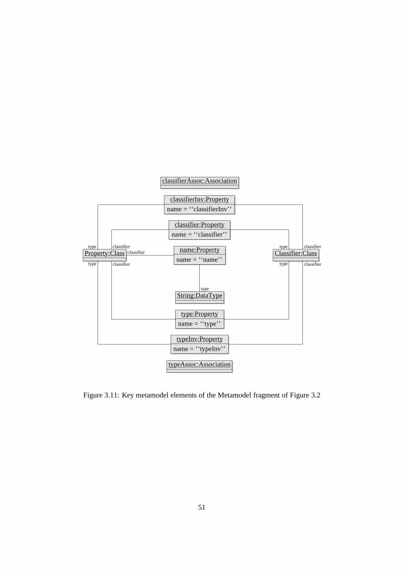
classifierAssoc:Association
classifierInv:Property
name = ‘‘classifierInv’’
classifier:Property
name = ‘‘classifier’’
type:Property
name = ‘‘type’’
name:Property
name = ‘‘name’’
String:DataType
typeInv:Property
name = ‘‘typeInv’’
typeAssoc:Association
Property:Class Classifier:Classtype
type
type
type
classifier
classifier
classifier
classifier
classifier
type
Figure 3.11: Key metamodel elements of the Metamodel fragment of Figure 3.2
51

useful for tool navigation of the models. ThexInv Properties will result in corre-sponding edges inγ′(mm) and thus allow inverse edges in the models. Althoughnavigation using these edges would be useful in modelling tools, they are not illu-minating for our present purposes since they are just backwards copies of the edgeswe are interested in.
We therefore introduce an economised version of the CC reading of class andobject diagrams. The CClite reading of a class diagram will be the object diagramgiven by the CC reading, except without the Associations andwithout Propertiesfor anonymous association ends, and obviously without the outgoingclassifierandtype links of these Properties. The CClite reading of an object diagram will bethe graph given by the CC reading, except without link nodes,and without edgesfor anonymous link ends. Therefore, the CClite reading of anobject diagramODwill instantiate the CClite reading of a class diagramCD iff the CC reading ofODinstantiates the CC reading ofCD. When we draw the graph obtained in this wayfrom an object diagram, the graph will appear as a minor notational variation ofthe object diagram. Thus we can work with less cluttered graphs, whilst retainingequivalent instantiation semantics, as we shall see below.
Note that this is only a temporary convenience, applicable here because of thelimited static semantics that we are interested in. In a legitimate UML systemstate, each link belonging to ann-ary Association is one node andn edges. Whenwe extend our definitions to cater for system dynamics, this will be stated formallybecause semantics for Actions and navigation expressions will depend on it.
The CClite reading of the metamodel fragment will be the “inner” part of Fig-ure 3.11, it will exclude the two Associations and the classifierInv and typeInvProperties. We obtain the model denoted by this object diagram using the CCliteinterpretation. This is not because it is the metamodel, butbecause it is an instanceof the metamodel, which we have decided has association end Properties owned byits Classes.
As a further economy, the Property nodes are identified with their String names.The resulting metamodel is shown as a graph in Figure 3.12. Its γ′ interpretationis shown in Figure 3.13. This is the same as the interpretation of the larger ver-sion with distinct Properties and Strings, so it has the sameγ′-instances or staticsemantics.
If we were to defineedge-labelledgraphs as functors, in the way Lambek andScott did with the diagram we reproduced in Figure 3.1, then Figure 3.13 is whatwe would use as the source category, except with different names. It also has acomforting resemblance to the class diagram from which it originated, in Figure3.2 on Page 36.
To make sense of the dual roles of the Property/String nodes,we will employthe power-graph treatment of multiple instantiation, introduced in the previous sec-tion. There are many label preserving homomorphismsmm // P(γ′(mm)), butwe show the image of the one which captures our intended object instantiation inFigure 3.14. Since it is a homomorphic image, it is a subgraphof P(γ′(mm)).
Now let us consider the apple-in-a-basket model again. Its metamodel elements
52

classifier name
Property
classifier
Classifier
type
type
classifiertype
name name
classifier
name
String
type
Figure 3.12: The metamodel fragment as a graph
Property Classifier
classifier
''Property Stringname //Property Classifier
type
77
Figure 3.13:γ′-interpretation of the metamodel fragment.
{Property,String} {Classifier}
classifier
''{Property,String}{Property,String}
name
VV{Property,String} {Classifier}
type
77
Figure 3.14: Subgraph of the metamodel power-graph given bythe self-instantiation homomorphism.
53
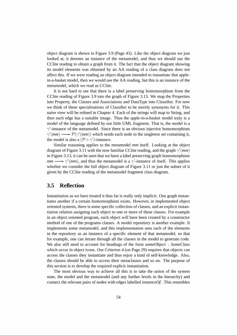
object diagram is shown in Figure 3.9 (Page 43). Like the object diagram we justlooked at, it denotes an instance of the metamodel, and thus we should use theCClite reading to obtain a graph from it. The fact that the object diagram showingits model elements was obtained by an AA reading of a class diagram does notaffect this. If we were reading an object diagram intended toinstantiate that apple-in-a-basket model, then we would use the AA reading, but thisis an instance of themetamodel, which we read as CClite.
It is not hard to see that there is a label preserving homomorphism from theCClite reading of Figure 3.9 into the graph of Figure 3.13. Wemap the Propertiesinto Property, the Classes and Associations and DataType into Classifier. For nowwe think of these specialisations of Classifier to be merely synonyms for it. Thisnaive view will be refined in Chapter 4. Each of the strings will map to String, andthen each edge has a suitable image. Thus the apple-in-a-basket model truly is amodel of the language defined by our little UML fragment. Thatis, the model is aγ′-instance of the metamodel. Since there is an obvious injective homomorphismγ′(mm) // P(γ′(mm)) which sends each node to the singleton set containing it,the model is also a(P ◦ γ′)-instance.
Similar reasoning applies to the metamodelmm itself. Looking at the objectdiagram of Figure 3.11 with the now familiar CClite reading,and the graphγ′(mm)in Figure 3.13, it can be seen that we have a label preserving graph homomorphismmm // γ′(mm), and thus the metamodel is aγ′-instance of itself. This applieswhether we consider the full object diagram of Figure 3.11 orjust the subset of itgiven by the CClite reading of the metamodel fragment class diagram.
3.5 Reflection
Instantiation as we have treated it thus far is really only implicit. One graph instan-tiates another if a certain homomorphism exists. However, in implemented objectoriented systems, there is some specific collection of classes, and an explicit instan-tiation relation assigning each object to one or more of these classes. For examplein an object oriented program, each object will have been created by a constructormethod of one of the programs classes. A model repository is another example. Itimplements some metamodel, and this implementation sees each of the elementsin the repository as an instance of a specific element of that metamodel, so thatfor example, one can iterate through all the classes in the model to generate code.We also still need to account for headings of the formsomeObject: SomeClasswhich occur in object icons. Our Criterion 4 (on Page 29) requires that objects canaccess the classes they instantiate and thus enjoy a kind of self-knowledge. Also,the classes should be able to access their metaclasses and soon. The purpose ofthis section is to develop the required explicit instantiation.
The most obvious way to achieve all this is to take the union ofthe systemstate, the model and the metamodel (and any further levels inthe hierarchy) andconnect the relevant pairs of nodes with edges labelledinstanceOf. This resembles
54

the approach of [GFB05].
Definition 8. If every node of a graph g has an outgoing instanceOf edge, we saythat g isinstantiated.
When theinstanceOfedges of a graphg determine a node map which can beextended to a homomorphism into some interpretationf (g), we have a rather spe-cial kind of system state. Such a system state contains and instantiates its model,which in turn contains and instantiates its self-instantiating metamodel. Impor-tantly, an object can navigate itsinstanceOfarrow(s) to find out what Class(es) itbelongs to. It can then followclassifierInvedges to find out what Properties itsClass has, and generally view the models description of itself and its world. Thisself-knowledge capability is sometimes calledreflection.
The explicit instantiation edges also give us an opportunity to refine our inter-pretation functionγ′. When we definedγ′, we derived the edges and nodes of thenew graph from the sources and targets of theclassifierandtypeedges of the oldgraph. A graph which contains the metamodel, and which has instantiation edgesexplicitly tells us what the nodes and edges of the dealgebraised graph should be.We define the edges of our dealgebraised graph to be the nodes with instanceOfedges into Property, and the nodes of this new graph to be nodes with instanceOfedges into Classifier.
For ill-formed models, it is possible that theclassifierandtypeedges will notdefine total functionssourceandtarget on the edges of the new graph. Definition9 takes care to exclude these models.
Another modification is needed from ourγ′ interpretation function. The graphsour function will apply to will containinstanceOfedges, and these will need suit-able images in the interpreted graph. It is Classifiers that are allowed to have in-
stances. That is,x i // C is OK in a graphg iff C i // Classifier there. (We
abbreviateinstanceOf // to just i //.) Also, note that Classifier is a Classifier, so we
will want Classifier i // Classifierin the metamodel, and hence in every systemstate. Now, the nodes of the interpreted graph will be exactly the instances of Clas-
sifier fromg, sox i // C is OK in g iff C is a node inγ(g). Also, theinstanceOfedges define a node map for which we need to find a compatible edge component.
Thus the arrowx i // C must map to an arrowC i // Classifier in γ(g), and
the arrowC i // Classifierin g must map to an arrowClassifier i // Classifierin γ(g). We see therefore that the desired behaviour is obtained by adding aninstanceOfedge into Classifier from every node inγ(g). Consider a (bad) graph
where something instantiates a non-Classifier. That isx i // y but there is no edge
y i // Classifier. In this case, there is nothing for the edgex i // y to map to.Indeed, there will be no nodey in γ(g), and so the proposed node component is notinto the right codomain, therefore it can not be extended to ahomomorphism2.
2An alternative to arbitrarily adding all theseinstanceOfedges is to add three Properties to the
55
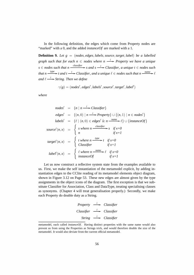
In the following definition, the edges which come from Property nodes are“marked” with a 0, and the addedinstanceOfare marked with a 1.
Definition 9. Let g = (nodes,edges, labels, source, target, label) be a labelled
graph such that for each n∈ nodes where n i // Property we have a unique
s∈ nodes such that nclassifier // s and s i // Classifier, a unique t∈ nodes such
that ntype // t and t i // Classifier, and a uniqueℓ ∈ nodes such that n name // ℓ
andℓ i // String. Then we define
γ(g) = (nodes′,edges′, labels′, source′, target′, label′)
where
nodes′ = {n | n i // Classifier}
edges′ = {(n, 0) | n i // Property} ∪ {(n, 1) | n ∈ nodes′}labels′ = {ℓ | (n, 0) ∈ edges′ & n name // ℓ} ∪ {instanceOf}
source′(n, x) =
{
s where nclassifier // s if x=0
n if x=1
target′(n, x) =
{
t where ntype // t if x=0
Classifier if x=1
label′(n, x) =
{
ℓ where n name // ℓ if x=0instanceOf if x=1
Let us now construct a reflective system state from the examples available tous. First, we make the self instantiation of the metamodel explicit, by adding in-stantiation edges to the CClite reading of its metamodel elements object diagram,shown in Figure 3.12 on Page 53. These new edges are almost given by the typeassignments in the object icons of the diagram. The first exception is that we sub-stitute Classifier for Association, Class and DataType, treating specialising classesas synonyms. (Chapter 4 will treat generalisation properly.) Secondly, we makeeach Property do double duty as a String.
Property i // Classifier
Classifier i // Classifier
String i // Classifier
metamodel, each calledinstanceOf. Having distinct properties with the same name would alsoprevent us from using the Properties as Strings trick, and would therefore double the size of themetamodel. It would also deviate from the current official metamodel.
56
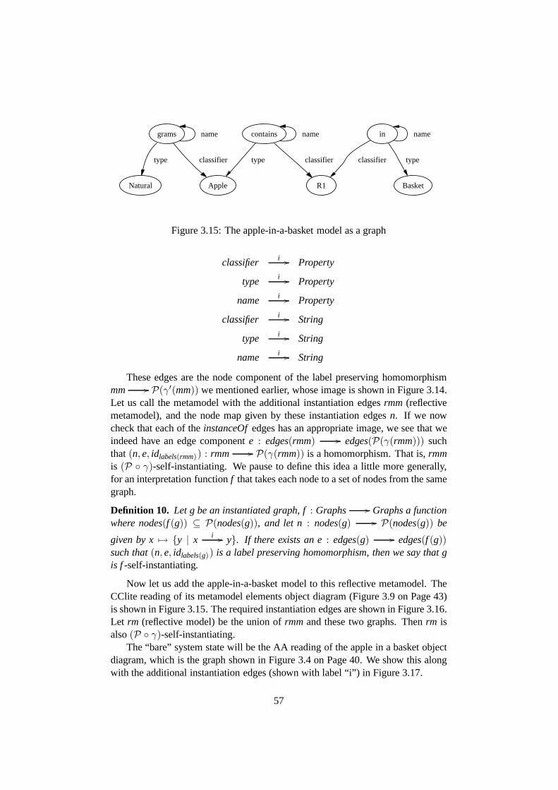
grams name
Apple
classifier
Natural
type
in name
R1
classifier
Basket
type
contains
type classifier
name
Figure 3.15: The apple-in-a-basket model as a graph
classifier i // Property
type i // Property
name i // Property
classifier i // String
type i // String
name i // String
These edges are the node component of the label preserving homomorphismmm // P(γ′(mm)) we mentioned earlier, whose image is shown in Figure 3.14.Let us call the metamodel with the additional instantiationedgesrmm (reflectivemetamodel), and the node map given by these instantiation edgesn. If we nowcheck that each of theinstanceOfedges has an appropriate image, we see that weindeed have an edge componente : edges(rmm) // edges(P(γ(rmm))) suchthat(n,e, idlabels(rmm)) : rmm // P(γ(rmm)) is a homomorphism. That is,rmmis (P ◦ γ)-self-instantiating. We pause to define this idea a little more generally,for an interpretation functionf that takes each node to a set of nodes from the samegraph.
Definition 10. Let g be an instantiated graph, f: Graphs // Graphs a functionwhere nodes(f (g)) ⊆ P(nodes(g)), and let n : nodes(g) // P(nodes(g)) be
given by x 7→ {y | x i // y}. If there exists an e: edges(g) // edges(f (g))such that(n,e, idlabels(g)) is a label preserving homomorphism, then we say that gis f-self-instantiating.
Now let us add the apple-in-a-basket model to this reflectivemetamodel. TheCClite reading of its metamodel elements object diagram (Figure 3.9 on Page 43)is shown in Figure 3.15. The required instantiation edges are shown in Figure 3.16.Let rm (reflective model) be the union ofrmmand these two graphs. Thenrm isalso(P ◦ γ)-self-instantiating.
The “bare” system state will be the AA reading of the apple in abasket objectdiagram, which is the graph shown in Figure 3.4 on Page 40. We show this alongwith the additional instantiation edges (shown with label “i”) in Figure 3.17.
57

Apple
Classifier
i
Natural
i
grams
Property
i
String
i
Basket
i
R1
i
in
ii
contains
ii
Figure 3.16: The instantiation edges of the apple-in-a-basket model
a
Apple
i
150
grams
Natural
i
b
Basket
i
l
contains in
R1
i
Figure 3.17: The apple-in-a-basket system-state, with itsinstantiation edges
58

The union of this graph andrm will be calledrss (reflective system state), andis also(P ◦ γ)-self-instantiating.
What we now have is a definition of a static modelling language, includingits semantics. The framework assumes that both the models (syntax) and snap-shots (semantics) of this language are graphs, and that the graphs which are partof this language are those that both contain the metamodel, and self-instantiate un-der some interpretation function. For the specific languagewe have developed, themetamodel ismmand the interpretation function isP ◦ γ.
This graph modelling language is both mathematically precise, and a nearenough approximation of the MOF subset of UML to allow us to study UML’ssyntax in Chapter 5. Before doing that though, it is necessary to revise our view ofobject diagrams to conform with the official UML definition [Obj07c].
3.6 Reconciliation of the Two Views
Seeing object diagrams as a variant of the traditional notation for graphs is a usefulaid to understanding, and has helped us introduce systems and models. Now wemust adjust our view to see them like class diagrams and otherUML diagrams, asrepresenting part of a model.
Each object icon in an object diagram represents an InstanceSpecification,which is “a model element that represents an instance” [Obj07c, §7.3.22]. TheInstanceSpecification has a linkclassifier to the Classifier that it represents aninstance of. A Slot [Obj07c,§7.3.48] represents a named value attached to aninstance. It has linksowningInstanceto its InstanceSpecification,valueto its Val-ueSpecification(s), and a linkdefiningFeatureto its Property. In an object diagram,thename= valueentries in the object icons, and the link ends all represent Slots.
When a Slot represents a link end, thevalue is an InstanceValue [Obj07c,§7.3.23], and must be linked to an InstanceSpecification. We see no reason why theInstanceSpecification should need this ValueSpecifications intermediary. A minorsimplification of the metamodel is therefore proposed. We will consider Instance-Specifications and ValueSpecifications to be specialisations of Specification, a newmetaclass of our own invention. We thus see another occurrence of the functordefinition of a graph. Figure 3.18 shows our new metamodel fragment in graph-form. (This is the decoded, post-dealgebraisation form, rather than the algebraiccoded form that exists within reflective system states.) Theoriginal metamodelfragment can be seen on the bottom line, and the new copy of thegraph defininggraph is on the top line. We will see shortly that, for well defined models, thetwo vertical arrows form a graph homomorphism. Another way of saying this isthat two squares within the diagram commute: one withowningInstanceand (thehorizontal)classifier, the other withvalueandtype.
The metamodel elements represented by the object diagram ofFigure 3.3 onPage 39 are shown in Figure 3.19. Applying a dealgebraisation analogous to theγ we employed on the class diagram metamodel elements, we obtain the graph
59
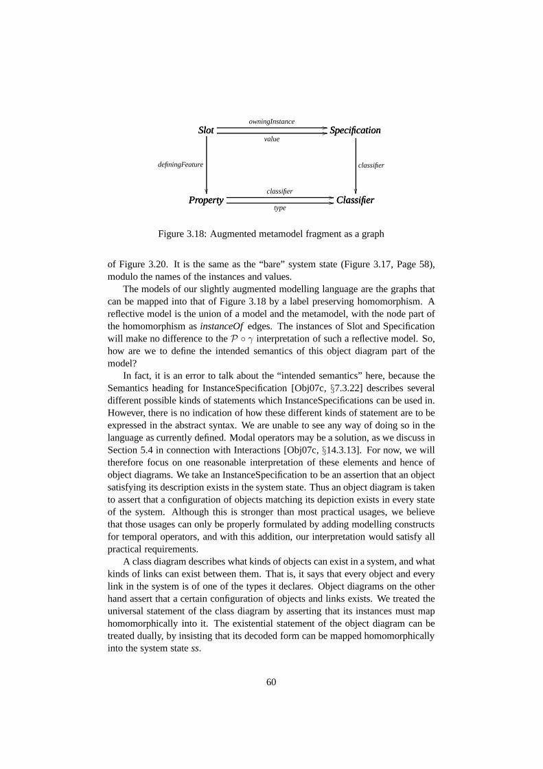
Slot SpecificationowningInstance //Slot Specification
value//Slot
Property
definingFeature
��
Specification
Classifier
classifier
��Property Classifier
classifier //Property Classifiertype
//
Figure 3.18: Augmented metamodel fragment as a graph
of Figure 3.20. It is the same as the “bare” system state (Figure 3.17, Page 58),modulo the names of the instances and values.
The models of our slightly augmented modelling language arethe graphs thatcan be mapped into that of Figure 3.18 by a label preserving homomorphism. Areflective model is the union of a model and the metamodel, with the node part ofthe homomorphism asinstanceOfedges. The instances of Slot and Specificationwill make no difference to theP ◦ γ interpretation of such a reflective model. So,how are we to define the intended semantics of this object diagram part of themodel?
In fact, it is an error to talk about the “intended semantics”here, because theSemantics heading for InstanceSpecification [Obj07c,§7.3.22] describes severaldifferent possible kinds of statements which InstanceSpecifications can be used in.However, there is no indication of how these different kindsof statement are to beexpressed in the abstract syntax. We are unable to see any wayof doing so in thelanguage as currently defined. Modal operators may be a solution, as we discuss inSection 5.4 in connection with Interactions [Obj07c,§14.3.13]. For now, we willtherefore focus on one reasonable interpretation of these elements and hence ofobject diagrams. We take an InstanceSpecification to be an assertion that an objectsatisfying its description exists in the system state. Thusan object diagram is takento assert that a configuration of objects matching its depiction exists in every stateof the system. Although this is stronger than most practicalusages, we believethat those usages can only be properly formulated by adding modelling constructsfor temporal operators, and with this addition, our interpretation would satisfy allpractical requirements.
A class diagram describes what kinds of objects can exist in asystem, and whatkinds of links can exist between them. That is, it says that every object and everylink in the system is of one of the types it declares. Object diagrams on the otherhand assert that a certain configuration of objects and linksexists. We treated theuniversal statement of the class diagram by asserting that its instances must maphomomorphically into it. The existential statement of the object diagram can betreated dually, by insisting that its decoded form can be mapped homomorphicallyinto the system statess.
60

Apple:Class Basket:ClassR1:Association
grams:Property
in:PropertyNatural:DataType
aSpec:Specification bSpec:SpecificationlSpec:Specification
spec150:LiteralInteger
value = 150
agrams:Slot
contains:Property
lcontains:Slot lin:Slot
classifier
definingFeature
classifier
owningInstance
value
classifier
definingFeature definingFeature
classifier
owningInstance owningInstance
value value
Figure 3.19: Metamodel elements of the apple-in-a-basket object diagram (Figure 3.3 on Page 39).
61

aSpec
Apple
i
spec150
grams
bSpec
Basket
i
lSpec
contains in
R1
i
Natural
i
Figure 3.20: Dealgebraisation of the object diagram metamodel elements
The node part of the homomorphismss // (P ◦ γ)(ss) is determined by in-stantiation edges. There is a similar restriction on the homomorphismsf (ss) //
ssthat will witness satisfaction of the object diagram: the Classifiers must map tothemselves. That is, although the object names do not matter, if a : Appleoccursin an object diagram, the node that represents this in the model must map to aninstance of Apple.
In the previous Section we identified a class of reflective system states, whichcontained the metamodel fragment and self-instantiated under our interpretation.Now, with an extended metamodel and a second interpretationfunction to expressthe existential semantics of object diagrams, these reflective system states can becharacterised by the following formula.
f (ss)idClassifiers // ss i // (P ◦ γ)(ss)
Heref is the object diagram elements interpretation function, and the arrows indi-cate homomorphic extensions of their named (partial) functions. When these twohomomorphisms exist, their composite is that given by the two vertical arrows ofFigure 3.18. In other words, the valid system states are exactly the factorisations(under function composition) of that graph homomorphism.
Our aim was to reconcile the direct interpretation of objectdiagrams, with theview that they represent metamodel elements. But in fact we have now produceda weaker interpretation than the direct one. The model obtained from the objectdiagram can be satisfied by a huge range of system states, but the direct read-ing gives a system state that is unique, up to label preserving isomorphism. Thehomomorphism view allows several object icons to denote thesame object, and
62
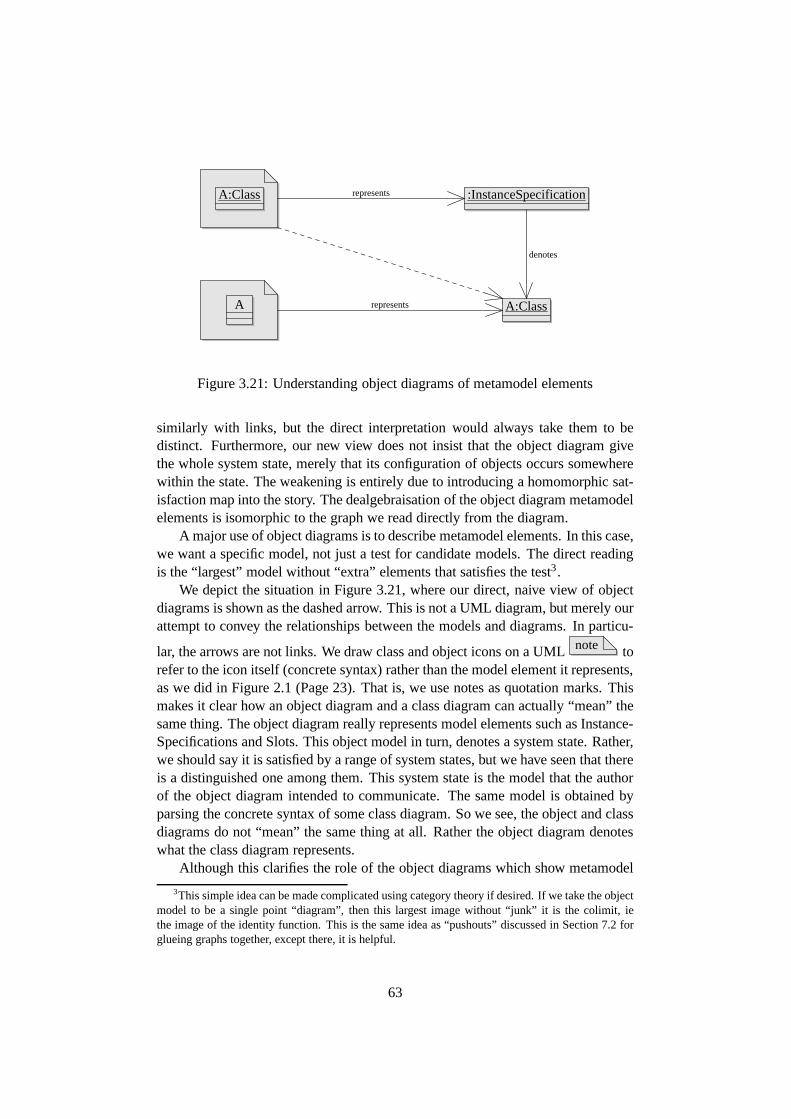
A
A:Class :InstanceSpecification
A:Class
represents
denotes
represents
Figure 3.21: Understanding object diagrams of metamodel elements
similarly with links, but the direct interpretation would always take them to bedistinct. Furthermore, our new view does not insist that theobject diagram givethe whole system state, merely that its configuration of objects occurs somewherewithin the state. The weakening is entirely due to introducing a homomorphic sat-isfaction map into the story. The dealgebraisation of the object diagram metamodelelements is isomorphic to the graph we read directly from thediagram.
A major use of object diagrams is to describe metamodel elements. In this case,we want a specific model, not just a test for candidate models.The direct readingis the “largest” model without “extra” elements that satisfies the test3.
We depict the situation in Figure 3.21, where our direct, naive view of objectdiagrams is shown as the dashed arrow. This is not a UML diagram, but merely ourattempt to convey the relationships between the models and diagrams. In particu-
lar, the arrows are not links. We draw class and object icons on a UML note torefer to the icon itself (concrete syntax) rather than the model element it represents,as we did in Figure 2.1 (Page 23). That is, we use notes as quotation marks. Thismakes it clear how an object diagram and a class diagram can actually “mean” thesame thing. The object diagram really represents model elements such as Instance-Specifications and Slots. This object model in turn, denotesa system state. Rather,we should say it is satisfied by a range of system states, but wehave seen that thereis a distinguished one among them. This system state is the model that the authorof the object diagram intended to communicate. The same model is obtained byparsing the concrete syntax of some class diagram. So we see,the object and classdiagrams do not “mean” the same thing at all. Rather the object diagram denoteswhat the class diagram represents.
Although this clarifies the role of the object diagrams whichshow metamodel
3This simple idea can be made complicated using category theory if desired. If we take the objectmodel to be a single point “diagram”, then this largest imagewithout “junk” it is the colimit, iethe image of the identity function. This is the same idea as “pushouts” discussed in Section 7.2 forglueing graphs together, except there, it is helpful.
63
elements, it is probably not the best way of thinking about them as they appear inChapter 5. Rather, this analysis justifies simply taking thediagrams at face value.
3.7 Conclusion
We now have a semantics for very basic UML class and object diagrams suffi-cient for us to study the the UML metamodel, and the syntax of particular models.Importantly, the semantics are derived from a careful studyof the official defini-tion, guided by the criteria we developed in Chapter 2. The semantic domain islabelled directed multi-graphs, and so is the abstract syntax. Each system-statecontains its model and each model contains its metamodel. Instantiation is madeexplicit by specially named edges. The class model is interpreted by a “dealgebrai-sation” function and power graph construction. The system state satisfies it whenthe instantiation edges are the node component of a graph homomorphism into thisinterpretation. Dually, the object model is dealgebraised, and is satisfied when aclass-preserving homomorphism exists into the system state.
We are not the first to propose that UML should be formally defined in termsof graphs. Our primary contribution is to argue for this based on a careful studyof the official, informal definition. Our use of interpretation functions is origi-nal, so far as we know. Instantiation is often formalised as graph homomorphism[BH02, EHHS00, ZHG05], but our introduction of interpretation functions has sev-eral advantages. It allows different parts of the model to beinterpreted in differentways, reflecting the different diagrams types used to specify those parts. With aninterpretation function, two or more levels of instantiation are possible. Withoutan interpretation function, every model is trivially self-instantiating, whereas wehave shown that a fragment of the UML metamodel is self-instantiating under ourdefinition, whilst models in general are not.
Another approach which can exhibit non-trivial self-instantiation is presentedin [GFB05]. There, Gogolla, Favre and Buttner “squeeze” the traditional four mod-elling levels “into a single object diagram”, in order to give precise definitions ofterms such as “strictness” and “potency”, which are common in the metamodellingliterature. In addition to explicit instantiation of nodesby nodes, second orderedges connect edges to the edges they instantiate. Thus the structure they workwith is not a traditional graph, but rather what they call a “layered graph”. Aftersome discussion, they arrive at the notion of a “strongly well-typed” layered graph,which amounts to saying that the typing edges form graph homomorpisms. Thisproposal does not match UML’s notion of instantiation. WithUML, edges at alower level instantiate nodes at the next higher level. For example, links instantiateAssociations, which are a kind of Classifier. The authors arenot alone in acceptingat face value the idea that object diagrams instantiate class diagrams, forgetting thatin UML, the class diagram is an abstraction of the actual model, which is more ac-curately rendered as another object diagram. Our approach makes this abstractionexplicit in the “dealgebraisation” interpretation function.
64
Graphs are a very expressive medium, but expressiveness canonly be gained atthe cost of analysability. The difficulty of analysing graphs is demonstrated by theproblem of finding embeddings of one graph in another. This problem is knownto be NP-complete, yet it will probably be involved in determining model instan-tiation and system state transition. It therefore seems likely that analysis of UMLmodels as graphs will be computationally intractable. However, this is not a reasonfor abandoning graphs in favour of some other formalism. Anything else suffi-ciently expressive would face the same problem. It seems likely that UML itselfis too expressive for automated analysis, and that any such analysis would requirefurther abstraction. The formalised definition that we seekfor UML would standas a reference to better understand the results of analysingmore abstract represen-tations. In Section 7.3, we discuss to what extent the analysis of an abstraction canyield understanding of the original.
In Chapter 5 we will carefully study the syntax and semanticsof a simple dy-namic UML model. But first, in the next Chapter, we examine some of the moresophisticated and troublesome aspects of the class diagramnotation used in theUML metamodel.
65
Chapter 4
Breaking the Symmetry ofAssociation Ends
This chapter continues our study of UML’s “repository semantics” which we beganin Chapter 3. The UML metamodel makes heavy use of the annotations {union}and{subsetsx} in its association ends. There is no agreed precise semantics forassociations, and many interpretations are possible. It has been noted [Obj, Issue#5977] that under some very plausible interpretations, theannotation{unique}is symmetrical. Symmetrical in the sense that if one association end is marked{unique} then the other end also has the property it signifies. It is undesirable forthese annotations to be symmetrical. If they were intended to apply to all endsof an association, they would be attached to the associationitself rather than to aparticular end.
At the time of writing, discussion on the{unique} annotation in the OMGforum on UML just cited seems to have reached the conclusion that a proposedinterpretation by Dragan Milicev [Mil06, Mil07] is a good solution to the problem.The naive view takes the annotation to be a constraint on whatlinks in the systemstate can belong to the association. Milicev instead sees itas a parameter of theassociation navigation action ReadLinkAction [Obj07c,§11.3.33].
Milicev does not address the{union} and{subsetsx} annotations, which wewill show also possess undesirable symmetry properties, even under reasonableinterpretations compatible with his proposal. Adopting the principles at work inMilicev’s proposal, and applying them more uniformly, we achieve an interpreta-tion which breaks the symmetry of these annotations as well.
Rather than focussing on ReadLinkAction and ReadStructuralFeatureAction,we frame the discussion in terms of the value of a models Properties, when theyoccur in a reflective system state. We find support in the official definition forviewing a Property as a function from the instances of its classifier to collectionsof values. Because of this, we must first develop a proper account of instantiationin the presence of generalisation, a task we deferred in the previous chapter. Theactions are then defined in terms of the Property values, which can also be used
66
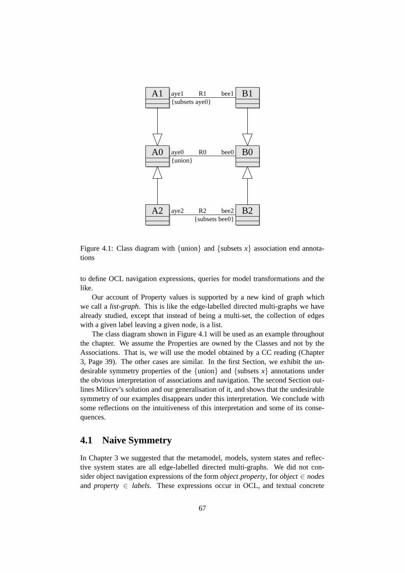
A0
A1
A2
B0
B1
B2
aye0{union}
bee0R0
aye1{subsets aye0}
bee1R1
aye2 bee2R2{subsets bee0}
Figure 4.1: Class diagram with{union} and{subsetsx} association end annota-tions
to define OCL navigation expressions, queries for model transformations and thelike.
Our account of Property values is supported by a new kind of graph whichwe call alist-graph. This is like the edge-labelled directed multi-graphs we havealready studied, except that instead of being a multi-set, the collection of edgeswith a given label leaving a given node, is a list.
The class diagram shown in Figure 4.1 will be used as an example throughoutthe chapter. We assume the Properties are owned by the Classes and not by theAssociations. That is, we will use the model obtained by a CC reading (Chapter3, Page 39). The other cases are similar. In the first Section,we exhibit the un-desirable symmetry properties of the{union} and{subsetsx} annotations underthe obvious interpretation of associations and navigation. The second Section out-lines Milicev’s solution and our generalisation of it, and shows that the undesirablesymmetry of our examples disappears under this interpretation. We conclude withsome reflections on the intuitiveness of this interpretation and some of its conse-quences.
4.1 Naive Symmetry
In Chapter 3 we suggested that the metamodel, models, systemstates and reflec-tive system states are all edge-labelled directed multi-graphs. We did not con-sider object navigation expressions of the formobject.property, for object∈ nodesand property ∈ labels. These expressions occur in OCL, and textual concrete
67
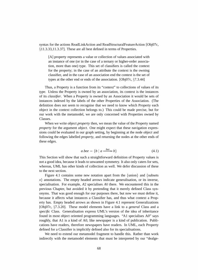
syntax for the actions ReadLinkAction and ReadStructuralFeatureAction [Obj07c,§11.3.33,11.3.37]. These are all best defined in terms of Properties.
[A] property represents a value or collection of values associated withan instance of one (or in the case of a ternary or higher-orderassocia-tion, more than one) type. This set of classifiers is called the contextfor the property; in the case of an attribute the context is the owningclassifier, and in the case of an association end the context is the set oftypes at the other end or ends of the association. [Obj07c,§7.3.44]
Thus, a Property is a function from its “context” to collections of values of itstype. Unless the Property is owned by an association, its contextis the instancesof its classifier. When a Property is owned by an Association it would be sets ofinstances indexed by the labels of the other Properties of the Association. (Thedefinition does not seem to recognise that we need to know which Property eachobject in the context collection belongs to.) This could be made precise, but forour work with the metamodel, we are only concerned with Properties owned byClasses.
When we writeobject.propertythen, we mean the value of the Property namedproperty for the argumentobject. One might expect that these navigation expres-sions could be evaluated in our graph setting, by beginning at the nodeobjectandfollowing the edges labelledproperty, and returning the nodes at the other ends ofthese edges.
a.bee= {b | a bee // b} (4.1)
This Section will show that such a straightforward definition of Property values isnot a good idea, because it leads to unwanted symmetry. It also only caters for sets,whereas, UML has other kinds of collection as well. We defer discussion of theseto the next section.
Figure 4.1 contains some new notation apart from the{union} and{subsetsx} annotations. The empty headed arrows indicate generalisation, or its inverse,specialisation. For example,A2 specialisesA0 there. We encountered this in theprevious Chapter, but avoided it by pretending that it merely defined Class syn-onyms. That was good enough for our purposes there, but now wemust define it,because it affects what instances a Classifier has, and thus what context a Prop-erty has. Empty headed arrows as shown in Figure 4.1 represent Generalizations[Obj07c, §7.3.20]. These model elements have a link to ageneralClass and aspecificClass. Generalisation express UML’s version of the idea of inheritancefound in most object oriented programming languages. “A1 specialises A0” saysroughly, that A1 is a kind of A0, like newspaper is a kind of publication. Publi-cations have readers, therefore newspapers have readers. In UML, each Propertydefined for a Classifier is implicitly defined also for its specialisations.
We need to extend our metamodel fragment to handle this. Rather than workindirectly with the metamodel elements that must be interpreted by our “dealge-
68
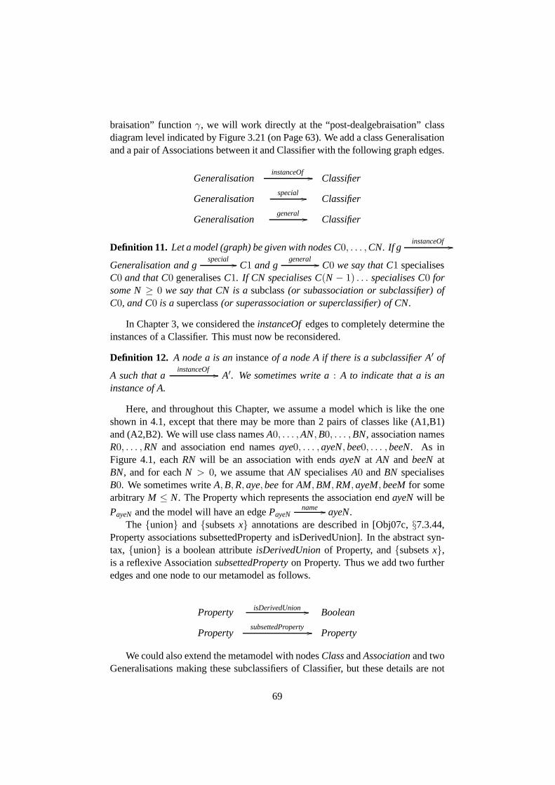
braisation” functionγ, we will work directly at the “post-dealgebraisation” classdiagram level indicated by Figure 3.21 (on Page 63). We add a class Generalisationand a pair of Associations between it and Classifier with the following graph edges.
GeneralisationinstanceOf // Classifier
Generalisationspecial // Classifier
Generalisationgeneral // Classifier
Definition 11. Let a model (graph) be given with nodes C0, . . . ,CN. If ginstanceOf //
Generalisation and gspecial // C1 and g
general // C0 we say that C1 specialisesC0 and that C0 generalisesC1. If CN specialises C(N − 1) . . . specialises C0 forsome N≥ 0 we say that CN is asubclass(or subassociation or subclassifier) ofC0, and C0 is asuperclass(or superassociation or superclassifier) of CN.
In Chapter 3, we considered theinstanceOfedges to completely determine theinstances of a Classifier. This must now be reconsidered.
Definition 12. A node a is aninstanceof a node A if there is a subclassifier A′ of
A such that ainstanceOf // A′. We sometimes write a: A to indicate that a is an
instance of A.
Here, and throughout this Chapter, we assume a model which islike the oneshown in 4.1, except that there may be more than 2 pairs of classes like (A1,B1)and (A2,B2). We will use class namesA0, . . . ,AN,B0, . . . ,BN, association namesR0, . . . ,RN and association end namesaye0, . . . ,ayeN,bee0, . . . ,beeN. As inFigure 4.1, eachRN will be an association with endsayeN at AN and beeNatBN, and for eachN > 0, we assume thatAN specialisesA0 andBN specialisesB0. We sometimes writeA,B,R,aye,beefor AM,BM,RM,ayeM,beeMfor somearbitraryM ≤ N. The Property which represents the association endayeNwill be
PayeN and the model will have an edgePayeNname // ayeN.
The {union} and{subsetsx} annotations are described in [Obj07c,§7.3.44,Property associations subsettedProperty and isDerivedUnion]. In the abstract syn-tax, {union} is a boolean attributeisDerivedUnionof Property, and{subsetsx},is a reflexive AssociationsubsettedPropertyon Property. Thus we add two furtheredges and one node to our metamodel as follows.
Property isDerivedUnion // Boolean
PropertysubsettedProperty // Property
We could also extend the metamodel with nodesClassandAssociationand twoGeneralisations making these subclassifiers of Classifier,but these details are not
69

relevant for the property annotations we are considering. We will continue to seeClass and Association as synonyms for Classifier.
The definition [Obj07c,§7.3.44, Property Semantics] says that a Propertyycan be marked{subsetsx} when “every element in the context of the subsettingproperty conforms to the corresponding element in the context of the subsettedproperty.” It is not clear what correspondence between elements this refers to. Inevery example we have seen in the metamodel, the subsetting Property is ownedby a Classifier that specialises the owner of the subsetted Property. In these cases,the corresponding element could be the same element. There is some confusionin the UML definition about whether an object of a special class is an instanceof its general classes [Obj07c,§7.3.20] or merely has acorresponding instancethere, as the present citation suggests. Some readers consider that each Class hasinstances, and an object consists of one instance from each Class in a branch ofthe specialisation forest. We prefer to avoid needlessly multiplying our entities.Another part of the definition offers some clarification on what it means for oneelement to “conform to” another. “A Classifier conforms to itself and to all itsancestors in the generalisation hierarchy” [Obj07c,§7.3.8]. We assume it meansthe instances of the Classifiers rather than the Classifiers themselves. Thus one casewhere subsetting is fairly clearly permitted is in CC interpretations of “squares”like our A0,B0,AN,BN whereayeNcan subsetaye0 andbeeNcan subsetbee0.Fortunately, all the occurrences we have seen in the metamodel are of this form.
When a Propertyy is marked{subsetsx}, that isysubsettedProperty // x in the
model, then “the collection associated with an instance of the subsetting propertymust be included in (or the same as) the collection associated with the correspond-ing instance of the subsetted property” [Obj07c,§7.3.44, Semantics]. Here we mustassume that the authors mean the instances of the owner of theProperty rather thaninstances of the Property. Definition 13 makes explicit whatwe take this passage tomean, where we temporarily take Equation 4.1 (on Page 68) to define the dot nota-tion. ThesubsettedPropertylink between the Properties is taken to be a constrainton the valid system states, so the definition says which system states “satisfy” thelink.
Definition 13. Let a graph be given where
e : PbeesubsettedProperty // Pbee0
Pbeeclassifier // A
Pbeename // bee
Pbee0name // bee0.
We say that e issatisfiedin that graph iff(∀ a : A) a.bee⊆ a.bee0.
Now let us see an example of the unwanted symmetry that arisesunder thisplausible view of Associations.
70
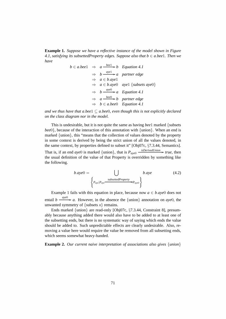
Example 1. Suppose we have a reflective instance of the model shown in Figure4.1, satisfying its subsettedProperty edges. Suppose alsothat b∈ a.bee1. Then wehave
b ∈ a.bee1 ⇒ a bee1 // b Equation 4.1
⇒ baye1 // a partner edge
⇒ a ∈ b.aye1⇒ a ∈ b.aye0 aye1 {subsets aye0}⇒ b
aye0 // a Equation 4.1
⇒ a bee0 // b partner edge⇒ b ∈ a.bee0 Equation 4.1
and we thus have that a.bee1 ⊆ a.bee0, even though this is not explicitly declaredon the class diagram nor in the model.
This is undesirable, but it is not quite the same as havingbee1 marked{subsetsbee0}, because of the interaction of this annotation with{union}. When an end ismarked{union}, this “means that the collection of values denoted by the propertyin some context is derived by being the strict union of all thevalues denoted, inthe same context, by properties defined to subset it” [Obj07c, §7.3.44, Semantics].
That is, if an endaye0 is marked{union}, that isPaye0isDerivedUnion // true, then
the usual definition of the value of that Property is overridden by something likethe following.
b.aye0 =⋃
8
<
:
Paye|Paye
subsettedProperty //Paye0
9
=
;
b.aye (4.2)
Example 1 fails with this equation in place, because nowa ∈ b.aye0 does not
entail baye0 // a. However, in the absence the{union} annotation onaye0, the
unwanted symmetry of{subsetsx} remains.Ends marked{union} are read-only [Obj07c,§7.3.44, Constraint 8], presum-
ably because anything added there would also have to be addedto at least one ofthe subsetting ends, but there is no systematic way of sayingwhich ends the valueshould be added to. Such unpredictable effects are clearly undesirable. Also, re-moving a value here would require the value be removed from all subsetting ends,which seems somewhat heavy-handed.
Example 2. Our current naive interpretation of associations also gives {union}
71
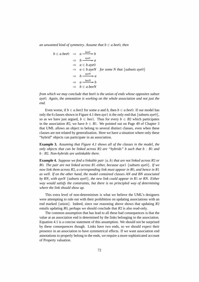
an unwanted kind of symmetry. Assume that b∈ a.bee0, then
b ∈ a.bee0 ⇒ a bee0 // b
⇒ baye0 // a
⇒ a ∈ b.aye0⇒ a ∈ b.ayeN for some N that{subsets aye0}⇒ b
ayeN // a
⇒ a beeN // b⇒ b ∈ a.beeN
from which we may conclude that bee0 is the union of ends whose opposites subsetaye0. Again, the annotation is working on the whole association and not just theend.
Even worse, ifb ∈ a.bee2 for somea andb, thenb ∈ a.bee0. If our model hasonly the 6 classes shown in Figure 4.1 thenaye1 is the only end that{subsetsaye0},so as we have just argued,b ∈ bee1. Thus for everyb ∈ B2 which participatesin the associationR2, we haveb ∈ B1. We pointed out on Page 49 of Chapter 3that UML allows an object to belong to several distinct classes, even when theseclasses are not related by generalisation. Here we have a situation where only these“hybrid” objects can participate in an association.
Example 3. Assuming that Figure 4.1 shows all of the classes in the model, theonly objects that can be linked across R2 are “hybrids” b such that b: B1 andb : B2. Non-hybrids are unlinkable there.
Example 4. Suppose we find a linkable pair(a,b) that are not linked across R2 orR0. The pair are not linked across R1 either, because aye1 {subsets aye0}. If wenow link them across R2, a corresponding link must appear in R0, and hence in R1as well. If on the other hand, the model contained classes AN and BN associatedby RN, with ayeN{subsets aye0}, the new link could appear in R1 or RN. Eitherway would satisfy the constraints, but there is no principled way of determiningwhere the link should show up.
This extra level of non-determinism is what we believe the UML’s designerswere attempting to rule out with their prohibition on updating associations with anend marked{union}. Indeed, since our reasoning above shows that updatingR2entails updatingR0, perhaps we should conclude thatR2 is also read-only.
The common assumption that has lead to all these bad consequences is that thevalue at an association end is determined by the links belonging to the association.Equation 4.1 is a concise statement of this assumption. We should not be surprisedby these consequences though. Links have two ends, so we should expect theirpresence in an association to have symmetrical effects. If we want association endannotations to properly belong to the ends, we require a moresophisticated accountof Property valuation.
72
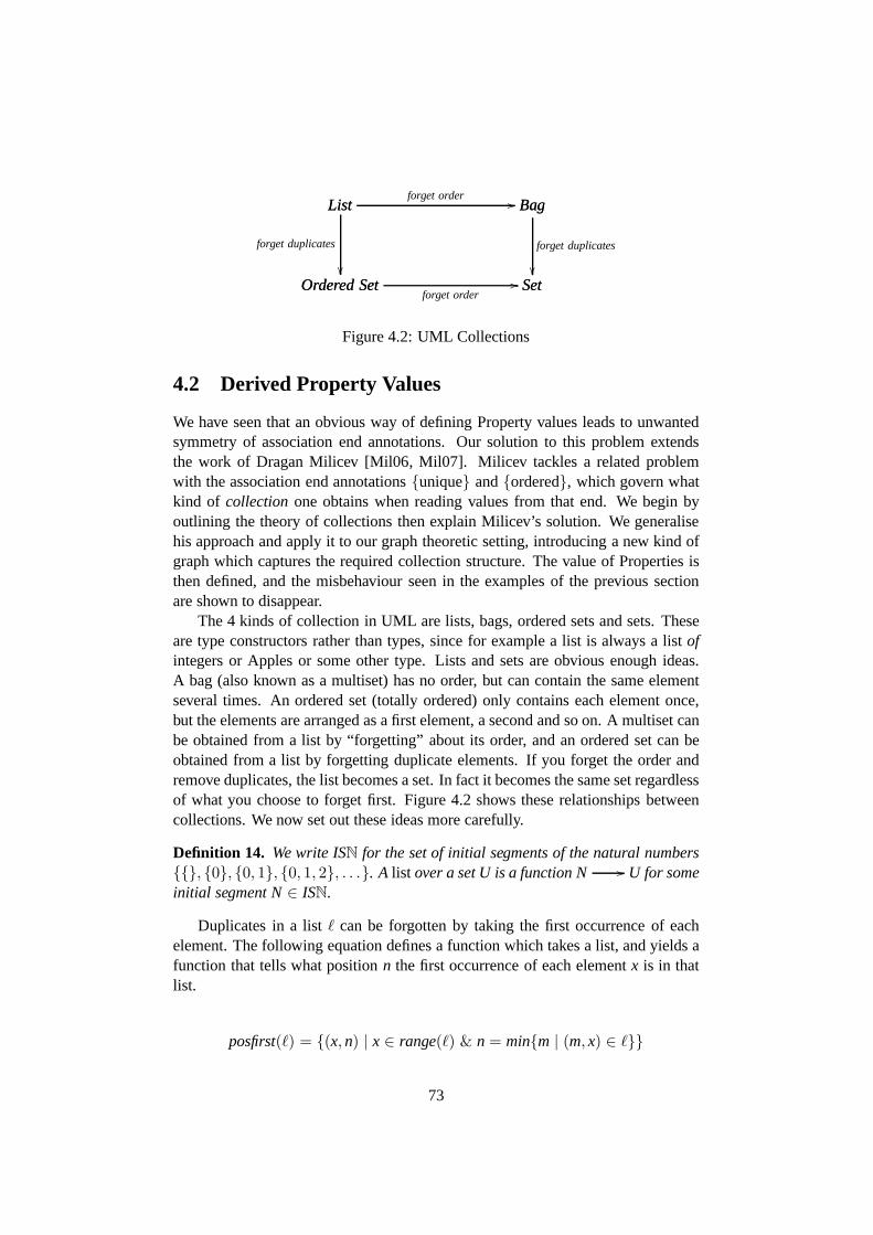
Ordered Set Setforget order
//
List
Ordered Set
forget duplicates
��
List Bagforget order // Bag
Set
forget duplicates
��
Figure 4.2: UML Collections
4.2 Derived Property Values
We have seen that an obvious way of defining Property values leads to unwantedsymmetry of association end annotations. Our solution to this problem extendsthe work of Dragan Milicev [Mil06, Mil07]. Milicev tackles arelated problemwith the association end annotations{unique} and{ordered}, which govern whatkind of collection one obtains when reading values from that end. We begin byoutlining the theory of collections then explain Milicev’ssolution. We generalisehis approach and apply it to our graph theoretic setting, introducing a new kind ofgraph which captures the required collection structure. The value of Properties isthen defined, and the misbehaviour seen in the examples of theprevious sectionare shown to disappear.
The 4 kinds of collection in UML are lists, bags, ordered setsand sets. Theseare type constructors rather than types, since for example alist is always a listofintegers or Apples or some other type. Lists and sets are obvious enough ideas.A bag (also known as a multiset) has no order, but can contain the same elementseveral times. An ordered set (totally ordered) only contains each element once,but the elements are arranged as a first element, a second and so on. A multiset canbe obtained from a list by “forgetting” about its order, and an ordered set can beobtained from a list by forgetting duplicate elements. If you forget the order andremove duplicates, the list becomes a set. In fact it becomesthe same set regardlessof what you choose to forget first. Figure 4.2 shows these relationships betweencollections. We now set out these ideas more carefully.
Definition 14. We write ISN for the set of initial segments of the natural numbers{{}, {0}, {0, 1}, {0, 1, 2}, . . .}. A list over a set U is a function N // U for someinitial segment N∈ ISN.
Duplicates in a listℓ can be forgotten by taking the first occurrence of eachelement. The following equation defines a function which takes a list, and yields afunction that tells what positionn the first occurrence of each elementx is in thatlist.
posfirst(ℓ) = {(x,n) | x ∈ range(ℓ) & n = min{m | (m, x) ∈ ℓ}}
73

From this we obtain an ordered set by lettingx≤ y iff posfirst(ℓ)(x) ≤ posfirst(ℓ)(y).The order ofℓ can also be forgotten to obtain a bag or multiset. A multiset is a
functionc : U // N, where the numberc(x) indicates how many occurrences ofx it contains.
c = {(x,n) | n = size{m | (m, x) ∈ ℓ}}Forgetting the duplicates of this multiset yields{x | c(x) ≥ 1} = range(ℓ).
We call a bag which actually contains duplicate elements a proper bag. Underthe naive interpretation of associations discussed in the previous section,a.beeisa proper bag iff the associationbeeis a proper bag iffb.aye is a proper bag. That
is, for somea there is someb for which we have more than one edgea bee // b.Since these edges always come in opposing pairs, there is also more than one edge
baye // a. If one end is marked{unique}, values at both ends are always sets.The essence of Milicev’s solution to this unwanted symmetryproblem is to de-
couple the contents of the association from the values obtained by reading its ends.An association for Milicev, is always a bag of links. If Property attributeisUniqueis true, then duplicate values in the collection are forgotten before the collectionis returned. He also solves a related problem with ends marked {ordered} by at-taching ordering annotations to the object references in the links. The specifiedcapabilities of the link actions CreateLinkAction and DestroyLinkAction [Obj07c,§11.3.14,11.3.17] for associations with an ordered end can not be achieved whenthe association is a list of ordinary links.
We would like a graph-like structure that can naturally handle UML’s orderedProperties. It seems unfortunate to have an ad-hoc semantics just for those as-sociations with the{ordered} annotation at one of their ends. We would like tosee uniform semantics, with the end annotations merely indicating which forgetfulfunctor should be applied. Recall that uniformity is an aid to understanding, andunderstandability is lacking in the current definition of UML. Ordering thelinks isnot a solution, because that also entails symmetry of the ordering at the associationends. However, we can achieve the desired uniformity by ordering the outgoingedgesin our graphs.
Definition 1 (on Page 39) defines a directed multi-graph as a set of edges, a setof nodes and a pair of parallel functions,sourceandtarget : edges // nodes. Letus consider alternative graph structures and ways of defining them. Ordinary (non-multi) directed graphs can be defined as a relation over a set of nodes,G⊆ nodes×nodes, or equivalently as a function which takes each node to the set of nodes at theother ends of its outgoing edges,g : nodes // 2nodes. Labels can be introducedby makingg a label-indexed family of functions
(
gℓ : nodes // 2nodes)
ℓ∈labels.Directedmulti-graphscan be similarly defined by replacing the node sets withmultisets. A pattern is emerging, suggesting that the nodes can be mapped to anycollectionof nodes. In the following definition, we take this pattern toits conclu-sion, where each label maps each node to alist of nodes.
74

Definition 15. A labelled directed list-graphg is a label-indexed family of functionsfrom the nodes to lists of nodes
(
gℓ : nodes //⋃
N∈ISN
nodesN)
ℓ∈labels
It is desirable to define these kinds of graphs as functors, aswe saw in Section3.1, so that the general theory of graph transformation systems [EEPT06] and othercategory theoretic machinery can be applied. We have not yetfound a way of doingthis. Also our power-graph construction of Definition 7 (on Page 49) does not applydirectly to list-graphs. The order forgetting functor mustbe applied to each nodevalue first to obtain a multi-graph.
We let reflective system states be list graphs, and are now ready to define thevalue of a PropertyP for a memberx of its context, in a system states. For a systemstates and edge labelname, the functionsname takes each node to a list of nodes.We will use this notation in what follows. The Property valuefunction and an aux-iliary function for the subsetted values are defined by mutual recursion. This re-places Equation 4.2 of the previous section, which only handled sets. The recursive
definition depends on there being no cycles or infinite chainsofsubsettedProperty //
edges.
Definition 16. Given a reflective system state s, a node P where Pi // Property
and Pclassifier // X for some X i // Classifier, and a node x: X, we define
subsettedVals(P, x) =⊕
P′∈subsettedPropertyInv(P)
FP′(value(P′, x))
where, FP′ is the forgetful functor from the collection type of P′ to the collectiontype of P, and⊕ is either list concatenation, multi-set union, concatenation fol-lowed by removal of duplicates, or set union, depending on the collection type ofP, and
value(P, x) =
{
subsettedVals(P, x) if P isUnionsubsettedVals(P, x) ⊕ FP(sname(P)(x)) otherwise
where FP is the forgetful functor from lists to the collection type ofP.
This only works if each subsetting property is at least as structured as the sub-setted property. Otherwise the required structure must be “invented” before thesubsetted property value can be given. For example, the subsetting property mightbe set-valued, but the subsetted property list valued. So, in what order do the ele-ments of the set appear? Constraint [5] in the definition of Property concerns thestrength of types in subsetting relationships, but this does not account for collec-tions, only the type of values in the collections.
75

:ReadStructurualFeatureAction bee:Property
denotes_a:InputPin
:OutputPin
object
result
structuralFeature
Figure 4.3: Model fragment represented by the textual expressiona.bee
Notice also that we rely on the subsettedProperties of a given Property to have aspecific order, which we use to correctly assemble the resulting list. There is actu-ally no indication in the definition of Property [Obj07c,§7.3.44] or the metamodeldiagram [Obj07c, Figure 7.12] that either end of the association subsettedPropertyis ordered. The opposite end should be, because without this, it is undeterminedwhich order the lists should be concatenated to yield the value of the subsettedProperty.
The actions ReadStructuralFeatureAction and ReadLinkAction can now be de-fined in terms of this property valuation function. Action execution will be con-sidered carefully in Section 5.6, here we just outline how itwill work. Considera system state in which a ReadStructuralFeatureAction [Obj07c, §11.3.37] is en-abled (ready to execute). A model fragment corresponding tothe expressiona.beeis shown in Figure 4.3. The ReadStructuralFeatureAction has a link object toa Pin ([Obj07c,§11.3.28], again see Section 5.6) containing the valuea and alink structuralFeatureto the Propertybee. Execution of the action will result invalue(bee,a) being placed on the OutputPin.
Now let us reconsider our examples from the previous sectionin the light of ournew definition of Property values. Example 1 fails becausea ∈ b.aye0 no longer
entails thatbaye0 // a. The value is inb.aye0 because of a link inR1, not one in
R0. Equation 4.2 already made this so in the presence of the{union} annotation,but Definition 16 does the job even without it.
The very first step fails in Example 2, becausebee2 {subsetsbee0}, and couldthus be the source of theb in a.bee0. This possibility is enough to justify the{union} belonging to an end rather than the association, but the situation herewarrants further investigation.
Let us consider a model represented by only the top square in Figure 4.1. Then
a bee0 // b doesfollow from b ∈ a.bee0. We noted before that CreateLinkActionsand DestroyLinkActions are not allowed for associations with a{union} end, likeour R0. We should not conclude from this thatR0 must be empty however. What-
76

everR0 contained in the initial system state, it will contain forever. Computer pro-grammers concerned with the initialisation of their systems are sometimes lead tothe fallacy that the initial state of a system is always empty. In fact, since all actionin UML systems is carried out by objects [Obj07c,§6.3.1,The Basic Premises],an empty system state can never evolve into a non-empty one. We should alsoremember that UML is moving beyond its software developmentorigins, and be-coming a general purpose language for describing systems ofdistributed objectswhich evolve in discrete steps.
We therefore allow the possibility thata bee0 // b. Because evaluation ofb.aye0 is now defined by Definition 16 and not Equation 4.1, it does notfollowthata ∈ b.aye0. That is, the{union} annotation actuallyhidestheR0 links fromthe annotated endaye0. Thus “preexisting” links inR0 are a second source ofasymmetry for this{union} annotated association.
Examples 3 and 4 depend on reasoning in Example 2, which we have shownno longer works under our new definition of association end navigation. Any pair(a,b) with a ∈ A2 andb ∈ B2 can be linked acrossR2 without any impact onthe contents ofR0 or R1. Similarly, changes to the contents ofR1 need not haveunpredictable consequences elsewhere.
4.3 Conclusion
Some UML users might be surprised to find that we can havea ∈ b.ayeyet b 6∈a.bee. Without this possibility though,{union} and{subsetsx} annotations can notproperly belong to association ends, but instead affect allends of the association.
We suspect that many UML features have consequences which clash with theintuitions of some UML users. The current definition of UML makes it difficultor impossible to determine what these consequences are. Ourattempts to clarifythe consequences of a couple of minor language features has cost us a great dealof effort, mostly trying to find a precise formulation which agrees with as muchas possible of the official definition. A precise official definition of the languagesemantics would enable theoretical workers to expose theseconsequences muchmore easily.
We believe that using UML to model a preexisting or required system canimprove stakeholder understanding and agreement, and thusimprove project out-comes. The quality of the understanding and agreement achieved is limited by theunderstanding of the language itself. Because of its visualnotation and familiarconcepts, UML is often seen as “easy to understand” comparedwith typical for-mal languages. However, the extent to which itcanbe understood is limited by theprecision of its definition.
In any case, we now have a precise enough definition of the semantics of thesubset of UML used to define UML’s abstract syntax. List graphs are the funda-mental structure used as system states, models and metamodels, and the valuesrepresented by Properties in reflective system states is nowdefined in a way that
77

makes good sense of the association end annotations. In the next chapter we studya small model which uses some of UML’s language of system dynamics. The se-mantics we have developed here will serve to make the syntax precise, and also asa foundation for the dynamic semantics of that model.
78
Chapter 5
Testing the Definition
The purpose of this chapter is to test the adequacy of the official definition ofUML [Obj07c]. The test we perform is to take a small example model, and seewhether we can infer its meaning by referring to the definition. In particular, theexample model appears to be inconsistent, so we wish to determine whether thisinconsistency is realised in the meaning that the definitiongives us. The examplemodel is presented in Section 5.1. It is inspired by an example of Stephen Mellor[HS05]. This test leads us to a thorough investigation of keyparts of the UMLdefinition. As a result, we develop an understanding of the dynamic aspects ofUML, and identify several conceptual flaws.
From Section 5.2, we begin parsing the model’s concrete diagrams into UML’sabstract syntax. This gives us the model as metamodel elements whose meaningcan be looked up in the definition. As a result of our work in Chapter 3, we canshow this abstract syntax using UML object diagrams withoutloss of precision.Section 5.2 discusses the UML definition document [Obj07c] and outlines the taskof parsing the diagrams and finding the meaning of the model elements. The classdiagram from the example model is parsed, finding many details of the abstractsyntax omitted in our preliminary work in Chapter 3. Section5.3 begins our studyof UML’s dynamics, introducing the notions of behaviour andevent. This first ap-proach to UML’s dynamics confronts many conceptual difficulties and distinctions.In Section 5.4 we parse and interpret the example sequence diagram, whose mean-ing is defined in terms of event occurrences. The section uncovers an apparentUML bug. Object behaviour and how it is caused is the subject of Section 5.5, andthe state machine diagram serves as our example of this. The penultimate Section5.6 looks at UML activities and actions, and in particular the entry action of oneof the state machine states. This Section also introduces graph transformation andoutlines how the prescriptive parts of the dynamic semantics could be precisely de-fined using this technique. The concluding Section 5.7 drawstogether the findingsof the Chapter to see whether the consistency of the model canbe determined fromthe UML definition.
79
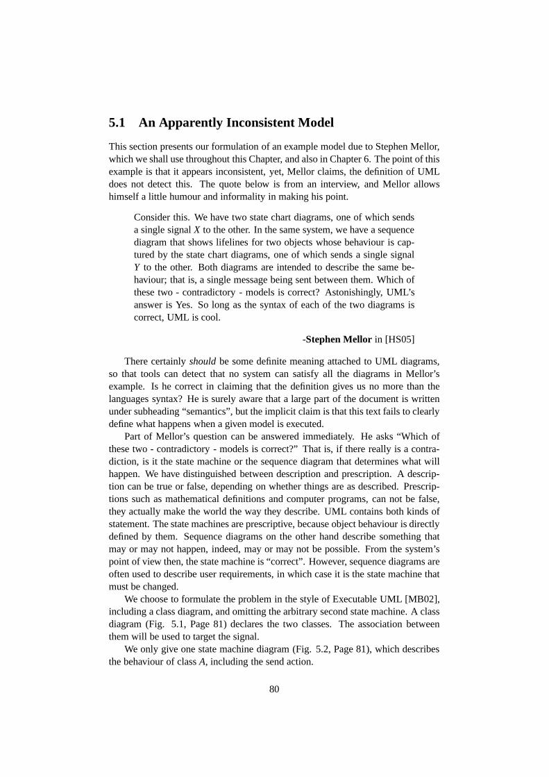
5.1 An Apparently Inconsistent Model
This section presents our formulation of an example model due to Stephen Mellor,which we shall use throughout this Chapter, and also in Chapter 6. The point of thisexample is that it appears inconsistent, yet, Mellor claims, the definition of UMLdoes not detect this. The quote below is from an interview, and Mellor allowshimself a little humour and informality in making his point.
Consider this. We have two state chart diagrams, one of whichsendsa single signalX to the other. In the same system, we have a sequencediagram that shows lifelines for two objects whose behaviour is cap-tured by the state chart diagrams, one of which sends a singlesignalY to the other. Both diagrams are intended to describe the samebe-haviour; that is, a single message being sent between them. Which ofthese two - contradictory - models is correct? Astonishingly, UML’sanswer is Yes. So long as the syntax of each of the two diagramsiscorrect, UML is cool.
-Stephen Mellor in [HS05]
There certainlyshouldbe some definite meaning attached to UML diagrams,so that tools can detect that no system can satisfy all the diagrams in Mellor’sexample. Is he correct in claiming that the definition gives us no more than thelanguages syntax? He is surely aware that a large part of the document is writtenunder subheading “semantics”, but the implicit claim is that this text fails to clearlydefine what happens when a given model is executed.
Part of Mellor’s question can be answered immediately. He asks “Which ofthese two - contradictory - models is correct?” That is, if there really is a contra-diction, is it the state machine or the sequence diagram thatdetermines what willhappen. We have distinguished between description and prescription. A descrip-tion can be true or false, depending on whether things are as described. Prescrip-tions such as mathematical definitions and computer programs, can not be false,they actually make the world the way they describe. UML contains both kinds ofstatement. The state machines are prescriptive, because object behaviour is directlydefined by them. Sequence diagrams on the other hand describesomething thatmay or may not happen, indeed, may or may not be possible. Fromthe system’spoint of view then, the state machine is “correct”. However,sequence diagrams areoften used to describe user requirements, in which case it isthe state machine thatmust be changed.
We choose to formulate the problem in the style of ExecutableUML [MB02],including a class diagram, and omitting the arbitrary second state machine. A classdiagram (Fig. 5.1, Page 81) declares the two classes. The association betweenthem will be used to target the signal.
We only give one state machine diagram (Fig. 5.2, Page 81), which describesthe behaviour of classA, including the send action.
80
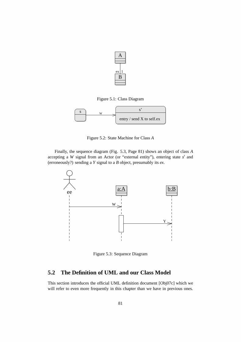
A
B1ex
Figure 5.1: Class Diagram
s
entry / send X to self.ex
s’W
Figure 5.2: State Machine for ClassA
Finally, the sequence diagram (Fig. 5.3, Page 81) shows an object of classAaccepting aW signal from an Actor (or “external entity”), entering states′ and(erroneously?) sending aY signal to aB object, presumably itsex.
ee a:A b:B
W
Y
Figure 5.3: Sequence Diagram
5.2 The Definition of UML and our Class Model
This section introduces the official UML definition document[Obj07c] which wewill refer to even more frequently in this chapter than we have in previous ones.
81
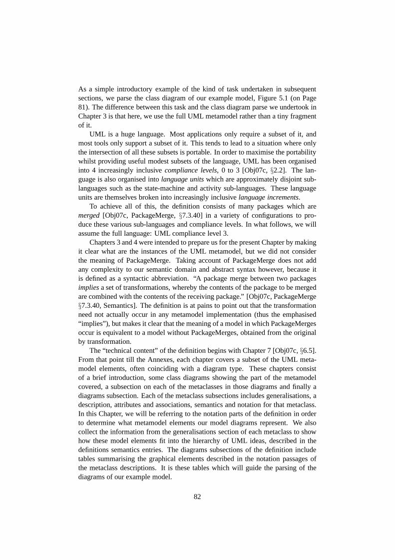
As a simple introductory example of the kind of task undertaken in subsequentsections, we parse the class diagram of our example model, Figure 5.1 (on Page81). The difference between this task and the class diagram parse we undertook inChapter 3 is that here, we use the full UML metamodel rather than a tiny fragmentof it.
UML is a huge language. Most applications only require a subset of it, andmost tools only support a subset of it. This tends to lead to a situation where onlythe intersection of all these subsets is portable. In order to maximise the portabilitywhilst providing useful modest subsets of the language, UMLhas been organisedinto 4 increasingly inclusivecompliance levels, 0 to 3 [Obj07c,§2.2]. The lan-guage is also organised intolanguage unitswhich are approximately disjoint sub-languages such as the state-machine and activity sub-languages. These languageunits are themselves broken into increasingly inclusivelanguage increments.
To achieve all of this, the definition consists of many packages which aremerged[Obj07c, PackageMerge,§7.3.40] in a variety of configurations to pro-duce these various sub-languages and compliance levels. Inwhat follows, we willassume the full language: UML compliance level 3.
Chapters 3 and 4 were intended to prepare us for the present Chapter by makingit clear what are the instances of the UML metamodel, but we did not considerthe meaning of PackageMerge. Taking account of PackageMerge does not addany complexity to our semantic domain and abstract syntax however, because itis defined as a syntactic abbreviation. “A package merge between two packagesimpliesa set of transformations, whereby the contents of the package to be mergedare combined with the contents of the receiving package.” [Obj07c, PackageMerge§7.3.40, Semantics]. The definition is at pains to point out that the transformationneed not actually occur in any metamodel implementation (thus the emphasised“implies”), but makes it clear that the meaning of a model in which PackageMergesoccur is equivalent to a model without PackageMerges, obtained from the originalby transformation.
The “technical content” of the definition begins with Chapter 7 [Obj07c,§6.5].From that point till the Annexes, each chapter covers a subset of the UML meta-model elements, often coinciding with a diagram type. Thesechapters consistof a brief introduction, some class diagrams showing the part of the metamodelcovered, a subsection on each of the metaclasses in those diagrams and finally adiagrams subsection. Each of the metaclass subsections includes generalisations, adescription, attributes and associations, semantics and notation for that metaclass.In this Chapter, we will be referring to the notation parts ofthe definition in orderto determine what metamodel elements our model diagrams represent. We alsocollect the information from the generalisations section of each metaclass to showhow these model elements fit into the hierarchy of UML ideas, described in thedefinitions semantics entries. The diagrams subsections ofthe definition includetables summarising the graphical elements described in thenotation passages ofthe metaclass descriptions. It is these tables which will guide the parsing of thediagrams of our example model.
82

We parsed an extremely simple class diagram, like that of ourcurrent exam-ple model, back in Chapter 3. We obtained the configuration ofobjects shownin Figure 3.9 (on Page 43) which included Classes, Associations and Properties.By consulting the table of graphic nodes in structure diagrams [Obj07c, Table 7.2,§7.4] we see that the class icons represent Classes. No surprises there. Similarlythe graphic paths table [Obj07c, Table 7.3,§7.4] tells us that the line between theclasses represents an Association. Although we have found no explicit statementthat attributes and association ends in the diagram represent Properties, this is clearfrom the relevant definition sections. So, the model elements represented by ourclass diagram will belong to the same metaclasses as we saw inChapter 3.
At that stage, we were working with a tiny fragment of the UML metamodel,so the resulting model was simple, with very few attributes and links. Now we arefaced with the full metamodel, what attributes and links will the Class, Associationand Property objects have? To determine this for the Classes, we must locate allthe different versions of Class in different packages in thedefinition. Each sectiondefining one of these versions lists the attributes and associations and describesthe semantics. But each of these versions of Class are also specialisations of othermetaclasses, and so they incorporate the attributes associations and semantics ofthese more general metaclasses. The generalisation hierarchies of two of the fourversions of Class are shown in Figures 5.4 (on Page 84) and 5.5(on Page 84). Thesefour different versions of Class are “merged” [Obj07c, PackageMerge,§7.3.40] toform the metaclass Class which our classes will instantiate.
Syntactically, the generalisations and the package mergesjust accumulate at-tributes and associations. It is complicated, but clear enough. It is not so clear howa coherent meaning is to be extracted from the generalisation and merge structureof the dozen or so short texts describing the semantics of these elements.
Association is defined only once in the definition, and most ofits generalisationhierarchy is above Classifier, which is already shown in Figure 5.4. The remainderof the generalisation hierarchy is shown in 5.6 (on Page 85).Each Associationis linked to at least two Properties called itsmemberEnds. The types of theseassociation ends are the Classes that the Association associates.
The metaclass Property is defined four times in the definition. The generalisa-tion hierarchy for the main one of these is shown in 5.7 (on Page 85).
Gathering associations and attributes from these hierarchies, we find that theclass diagram of our example model represents the model elements shown in Figure5.8 (on Page 86). Not all attributes are shown, because thereare too many. Forexample, Property has over 20 attributes. Many of the association ends in themetamodel are marked{subsets...}, where... is some other association end we callthesubsettingproperty. We discussed this annotation at length in Chapter4, wherewe decided that it is an indication to the navigation expression evaluator to includethe values of this property when evaluating the subsetting property. Definition16 (on Page 75) states this formally. We indicate subsettingby placing severalend names at the ends of the link paths in the diagram. Although our purposein Chapter 4 was to make it possible for these{subsets...} annotations to properly
83
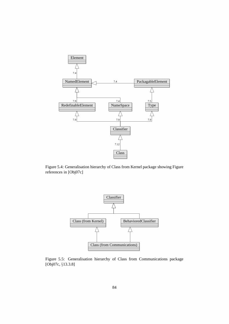
Class
Classifier
RedefinableElement NameSpace Type
NamedElement PackagableElement
Element
7.12
7.9 7.9 7.9
7.9
7.4
7.4 7.5
7.4
Figure 5.4: Generalisation hierarchy of Class from Kernel package showing Figurereferences in [Obj07c]
BehavioredClassifier
Classifier
Class (from Kernel)
Class (from Communications)
Figure 5.5: Generalisation hierarchy of Class from Communications package[Obj07c,§13.3.8]
84
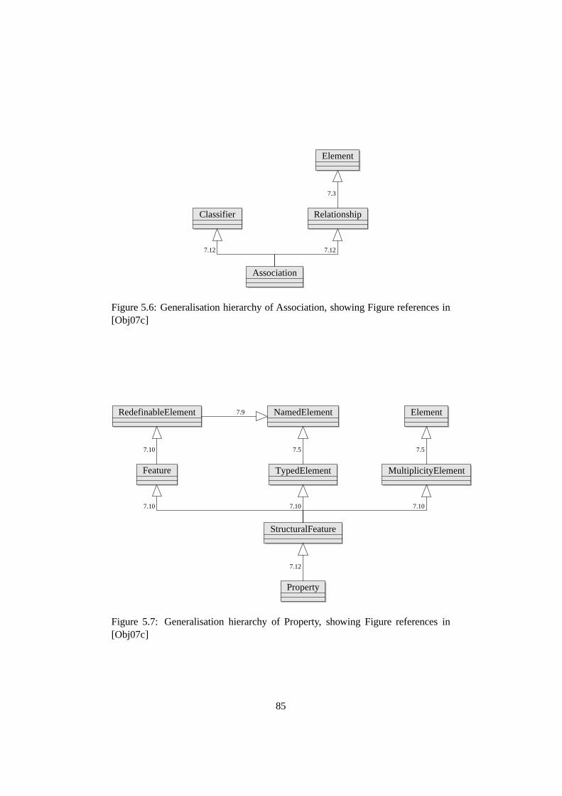
Association
Classifier Relationship
Element
7.12 7.12
7.3
Figure 5.6: Generalisation hierarchy of Association, showing Figure references in[Obj07c]
RedefinableElement ElementNamedElement
Feature MultiplicityElementTypedElement
StructuralFeature
Property
7.12
7.107.10 7.10
7.10 7.57.5
7.9
Figure 5.7: Generalisation hierarchy of Property, showingFigure references in[Obj07c]
85

A:Class
name = ‘‘A’’/qualifiedName = ‘‘A’’visibility = publicisLeaf = falseisAbstract = falseisActive = true
:Property
isLeaf = falseisStatic = falseisOrdered = falseisUnique = trueisReadOnly = falseaggregation = noneisComposite = falseisDerived = falseisDerivedUnion = false
:Association
isDerived = falsevisibility = publicisLeaf = falseisAbstract = falseisDerived = false
ex:Property
name = ‘‘ex’’isLeaf = falseisStatic = falseisOrdered = falseisUnique = true/lower = 1/upper = 1isReadOnly = falseaggregation = noneisComposite = falseisDerived = falseisDerivedUnion = false
:LiteralUnlimitedNatural
value = 1
:LiteralInteger
value = 1 B:Class
memberEnd
association
ownedElement
owner
member
-
ownedMember
namespace
feature
featuringClassifier
attribute
classifier
ownedAttribute
class
type
owner
-namespace
ownedElementmember
ownedMember
featuringClassifierclassifierclass
featureattribute
ownedAttribute
type
upperValue
lowerValue
memberEnd
association
Figure 5.8: Metamodel elements of the class diagram
apply to one end rather than being symmetric, they are often used in the metamodelin pairs, one on either end of an association. We have indicated these pairings byputting each name in the same position as its partner at the other end. Where nopartner name exists, we indicate this by putting a ‘-’ in its place. We have shown thevalues of some derived attributes, using the usual /-prefix notation. The associationend Properties are owned by the end classes rather than the Association. As wediscussed in Chapter 3, when no ownership dots [Obj07c,§7.3.3, notation] areshown in a diagram, any uniform reading is permissible.
The complex packaging and generalisation structure of the definition makes ita very time-consuming and error-prone task to determine exactly what any givenmodel element consists of, and what the resulting element means. Our parse of theexample model was executed initially without any tool support, just by reading thedefinition. We later checked the model by entering it in the open source UML 2.1implementation of the Eclipse Modelling Framework [Ecl07]. None of this waseasy, and we can not be completely confident that this parse is“correct”. This task
86

has been referred to as “navigating the metamuddle” [FGDTS06]. That paper andour discussions with other researchers confirm that our experience is a commonone.
5.3 UML Dynamics
In Chapter 3, we developed a tentative semantics for the static fragment of UMLused in the UML metamodel. This has enabled an unambiguous account of theabstract syntax. The example model we are studying in this chapter includes staticelements such as Classes and Associations, but also employsdynamic parts of thelanguage, such as Events, Behaviors and States. This section develops an overviewof the dynamic aspects of UML in preparation for the detailedwork of the next fewsections.
The main ideas of UML’s dynamics are best introduced by some key quotesfrom the definition. “A model contains three major categories of elements: Clas-sifiers, events, and behaviors.” [Obj07c,§6.4.1]. A classifier “describes a setof instances that have features in common” [Obj07c,§7.3.8]. “An event is thespecification of some occurrence that may potentially trigger effects by an object.”[Obj07c,§13.3.13]. “Behavior is a specification of how [the instancesof] its con-text classifier change[s] state over time.” [Obj07c,§13.3.2]1. Classifiers are themajor element for describing the statics of the system, whilst events and behaviorsdescribe the dynamics.
The words “behavior” and “event”, and much of the description in the defini-tion leads us to think that behavior is aboutprescriptivedynamics, whereas eventsaredescriptive. This distinction between description and prescription was intro-duced in Section 1.3. StateMachines and Activities are kinds of Behavior, andthese are a kind of programming, instructing the objects howto behave. Perhapssurprisingly, Behaviors are also a kind of Classifier. Whenever a behavior is exe-cuting, it actually exists in the system state as an instanceof the Behavior, oftencalled abehavior execution. We will examine behavior executions more carefullyin Section 5.4.
In our example model, Events are used in the sequence, and also as the transi-tion trigger in the state machine. Figure 5.9 (on Page 88) shows the generalisationhierarchies of the kinds of Event represented by the examplesequence diagram.In both kinds of usage, Events play the role of a condition of the form “such-and-such happens”. In the state machine, it is “when such-and-such happens, make thisstate transition”. In the sequence, the events are combinedin a temporal order todescribe a more complex happening. Reggio and co-authors suggest that temporallogic is needed for a formal treatment of sequence diagrams [RCA01]. We pursuethis suggestion in Chapter 6 (published as [O’K06a]). However this view of Events
1Even the authors of the definition occasionally fail to distinguish between a classifier and itsinstances. The square brackets [] show what is clearly intended.
87

PackagableElement
Event
ExecutionEvent
MessageEvent
SendSignalEvent ReceiveSignalEvent
Figure 5.9: Generalisation hierarchies of some required kinds of Event
and sequence diagrams as temporal conditions isnot supported by a more carefulreading of the definition.
Sequence diagrams represent Interactions [Obj07c,§14.3.13]. These are notas we might expect, a kind of compound Event, but a Behavior. The generalisa-tion hierarchy of Interaction can be seen in Figure 5.10 (on Page 89), along withthose of the required OccurrenceSpecifications, which we will discuss shortly. AnInteraction is not a behavior of any particular kind of object, but an “emergent” be-havior in which several objects may participate. Behavior is a Classifier, so like thebehavior of a particular object, the instances of an Interaction exist at run-time. Forthe prescriptive dynamics of an object, this is fine. The Behavior instance is like anexecuting process in an operating system, it has a clear identity that can be tracedthrough time. It exists while the process is executing, and ceases to exist when theprocess terminates. An Interaction can not be like this. Theexecution of a UMLsystem is non-deterministic. The beginning of an Interaction can happen, but wejust have to wait and see whether or not the rest of it will happen as described. Ifthe behavior exists exactly when what it represents is happening, then whether itexists at a time when part of it has happened depends on what will happen in thefuture. That is clearly nonsense2. If we can make any sense of Interactions as akind of Behavior, then it is a very different kind of behaviorto the behavior of aclassifier. The behavior instance can only come into existence after the describedbehavior has happened.
Reclassifying Interactions as a kind of Event would still not allow us to treat
2The situation may be compared to that of Schrodingers cat, which is meant to be both alive anddead.
88

NamedElement
InteractionFragment MessageEnd
OccurrenceSpecification
ExecutionSpecification
ExecutionOccurrenceSpecification
MessageOccurrenceSpecification
Behavior
Interaction
Figure 5.10: Generalisation hierarchies of Interaction and the OccurrenceSpecifications
89
them as temporal logic formulae. This is because events, like behaviors, are alsoindividuals that exist in the run-time system state.
The “Overview” Section of Chapter 13 of the definition describes the dynamicaspects of UML’s run-time semantics. To do so it employs a series of “domainmodels”, which it is careful to point out “are not metamodelsbut show objectsin the semantic domain and relationships between these objects” [Obj07c,§13.1].That is, these run-time domain models are models at the same level as ordinaryUML models, but they are universal, in the sense that they model every possi-ble UML run-time system state. The domain models are “informal”, that is, non-normative, but as we show in Section 8.1 and Figure 8.4 (on Page 169), they couldeasily play an important role in making the run-time semantics precise. In Chapter3, we developed an account of system state instantiation of aclass model as graphhomomorphism. The domain models could be incorporated by demanding that amodelled system state be homomorphically mapped into a combination of the usermodel and the semantic domain model.
In any case, the run-time domain model shows us what kinds of things we canfind in a run-time system-state. An instance of an Event is called an occurrence[Obj07c,§6.4], and Figure 13.2 in the definition shows a class EventOccurrence aspart of a domain model. It is clear that these occurrences arenot merely derivativeof the difference between a system state and its predecessor, but are actual persis-tent entities in their own right: “When an event occurrence is recognized by anobject, it may have an immediate effect or the event may be saved in an event pooland have a later effect when it is matched by a trigger specified for a behavior.”[Obj07c,§13.1] There is further talk of occurrences being saved in “event pools”,“consumed” and so on, in [Obj07c, BehavioredClassifier,§13.3.4; AcceptEven-tAction, §11.3.2].
Events and their occurrences must be distinguished from therelated ideas Sig-nal [Obj07c,§13.3.24] and Message [Obj07c,§14.3.20]. Signal is a kind of Clas-sifier, and the instances of a Signal are units of asynchronous communication be-tween objects. The generalisation hierarchy of Signal can be seen in Figure 5.11(on Page 91). It would be more natural to call these things “messages”, howeverMessage is reserved for another related concept. “A Messagedefines a particu-lar communication between Lifelines of an Interaction.” [Obj07c,§14.3.20]. Thegeneralisation hierarchies of Message, and another important sequence diagrammetaclass Lifeline, are shown in Figure 5.12 (on Page 91). The kinds of communi-cation that the Message can represent include a Signal instance, a (synchronous orasynchronous) operation call, and creating or destroying an instance. On the faceof it, Signal instances and operation calls are entirely different kinds of things. Sig-nal is a classifier, so its instances are like objects, but an operation call is an action.However, the definition of that action makes it clear that, again a persistent entity isinvolved “CallOperationAction is an action that transmitsan operation call requestto the target object” [Obj07c,§11.3.10]. The “domain model” shown in [Obj07c,Figure 13.3] has a class Request. “Several kinds of requestsexist between in-stances, for example, sending a signal or invoking an operation.” [Obj07c,§13.1].
90

Classifier
Signal
Figure 5.11: Generalisation hierarchy of Signal
NamedElement
Lifeline Message
Figure 5.12: Generalisation hierarchies of Lifeline and Message
Thus Message is like an instance specification for Requests.The domain modelshows that each Request has a sending and receiving object, as well as sending andreceiving event occurrences.
Let us now summarise what we know about Events, Signals and Messages.Signals are like Classes. We use them to model the kinds of asynchronous mes-sages that can be sent between objects in the target system. Their instances, likeobjects, have name-value pairs which constitute the content of the message. Wecan define kinds of signal by adding Signal elements to our model. Although it isnot shown in the metamodel, Signal is “generalised” by Request, which also clas-sifies the persistent entities which realise operation calls. Request instances canbe specified by a Message. Events on the other hand are part of UML’s run-timemachinery. We can not define new kinds of event, the availablekinds are specifiedby the UML metamodel3.
This “run-time machinery” defines the behavior of the systems which UMLmodels describe. It must take responsibility for creating the event occurrences.That is, whenever something happens which an event occurrence can represent,the appropriate event occurrences must be added to the system state. This seemsunproblematic for events representing sending or receipt of signals or operationcalls, creation and destruction of objects, or the beginning or end of a behaviorexecution. The rules which define these system state changesmust also specify thecreation of the corresponding event occurrences.
3New event types could be defined using a profile [Obj07c,§18], but this amounts to defining anew language based on UML
91
It is not so obvious how TimeEvent and ChangeEvent [Obj07c,§13.3.27,§13.3.7]occurrences should be created. These events are different in two ways from thosejust discussed. Firstly, they are not directed toward any particular object. If ob-ject a calls an operation of objectb, then the InvocationOccurrence hasa as itssender, and the ReceiveOccurrence hasb as its receiver [Obj07c, Figure 13.3]. AChangeEvent has a boolean expression, and the event “occurs” when the value ofthe expression goes from false to true (it does not occur whenthe value goes fromtrue to false). The occurrence is not related to any particular object. Similarly, aTimeEvent has a time expression, and the event “occurs” at that time. Creation-Event and DestructionEvent [Obj07c,§14.3.6,14.3.7] occurrences are also presum-ably not directed toward any particular object, or at least in the case of Destruction-Event, not for very long! We shall return to this point shortly in Section 5.4. Thesecond way in which TimeEvent and ChangeEvent occurrences differ from the ob-ject specific ones is that there will be infinitely many of them, even when there areonly finitely many objects in the system state. There are obviously infinitely manypoints in time, and infinitely many boolean expressions change from false to truewith every change in system-state.
This is the way UML is defined, but there is an equivalent formulation thathas the advantages of being finite and more uniform. For theseobject-independentevents, it seems more natural for the run-time machinery to be “aware” of the Eventelements in the model, and to create the occurrences only when they are relevant.Where such occurrences are relevant, they are relevant onlyto certain objects, so,they can be “directed” toward them (by some appropriately labelled edge), thusachieving a uniform treatment of occurrences. This relevance principle could beextended to the other events. Although probably not helpfulfor our theory, thiswould be a useful optimisation for an implementation of the UML run-time.
We have seen that UML’s dynamics adds a lot of new kinds of entity to thesystem states. Things that we would have expected to be transient, like eventsand operation calls are actually first-class inhabitants ofthe system state. We havealso seen some difficulties with the formulation of UML’s dynamics. Emergent be-haviour should not be represented by persistent entities, because its not clear whenthey exist. Parts of the definition assume that all event occurrences are directedat particular objects, but this fails to account for time andchange and destructionevents. Despite these problems, the overall picture seems reasonably clear. We arenow ready to study the diagrams and model elements concernedwith dynamics.
5.4 Emergent Behavior
The sequence diagram of our example model, shown in in Figure5.3 (on Page 81),represents an Interaction [Obj07c,§14.3.13]. This is a kind of emergent Behavior.Although we found difficulties with this UML notion in the previous section, wewill persist with it here to see to what extent we can make sense of it, and whatmight be done to improve it. Since the event occurrences referred to by the se-
92
quence diagram are actually there in the system state, we do not need the semanticapparatus of temporal logic to understand them. In fact, we can treat them in muchthe same way as an object diagram: as a graph which must map homomorphicallyinto the system state.
Figures 5.13 (on Page 94) and 5.14 (on Page 95) show most of themodelelements represented by the example sequence diagram of Figure 5.3 (on Page 81).We have not shown the GeneralOrderings, which say in what order the occurrencesmust happen [Obj07c,§14.3.12]. The main units of meaning of such an Interactionare the OccurrenceSpecifications. These are qualified by an Event and a Lifeline.The MessageOccurrenceSpecifications are also qualified by aMessage, and theExecutionOccurrenceSpecifications by a BehaviorExecutionSpecification.
The Event represents a collection of related occurrences. SendSignalEventsand ReceiveSignalEvents each refer to a signal, and are thusfairly specific aboutthe occurrences they represent. ExecutionEvents [Obj07c,§14.3.8] on the otherhand have no means to specify whether it is the beginning or the end of a behaviorexecution that they represent, nor what behavior the execution instantiates. Thatis, every ExecutionEvent represents the beginning and end occurrences of everybehavior execution.
Our Interaction uses the ExecutionEvents and ExecutionOccurrenceSpecifi-cations in the context of a BehaviorExecutionSpecification, which links tostartand finish ExecutionOccurrenceSpecifications. Message similarly distinguishesbetweensendEventandreceiveEvent, but there are also distinct Event metaclassesfor send and receive events. One could construct an Interaction in which the sendE-vent of a given Message actually specifies a receipt occurrence. The resulting In-teraction would presumably be unsatisfiable.
Let us now consider what this interaction should look like asa graph. Similarlyto class and object diagrams (Chapter 3), we hope to treat theInteraction by apply-ing an interpretation function to the system state which will pick out the relevantmodel elements and produce a graph which is satisfied if it maps homomorphicallyinto that system state. What follows is an investigation into what this interactioninterpretation function ought to do, and what the historical parts of the system stategraph ought to look like.
Events classify occurrences in much the same way classes classify objects.There may be occurrences which are classified by no Event, forexample, a modelmight not have any Events in it, but there will still be occurrences in its systemstates. We have already established that an object can instantiate more than oneclass. Since the ReclassifyObjectAction [Obj07c,§11.3.39] associationnewClas-sifier has lower bound 0, it is also possible for an object to instantiate no class.It therefore seems appropriate to use instantiation edges in the graph form of thesystem state to show which occurrences are represented by which Events.
If Events are analogous to Classes, then OccurrenceSpecifications are analo-gous to InstanceSpecifications. They represent a single event occurrence whichinstantiates its associated Event. We can achieve this in a system state graph byturning theeventlinks in the model elements object diagrams of Figures 5.13 and
93

ee:Lifeline
w_send:MessageOccurrenceSpecification
wm:Messagew_send_event:SendSignalEvent
a:Lifeline
w_rec:MessageOccurrenceSpecification
w_rec_event:ReceiveSignalEvent
w:Signal
y_send:MessageOccurrenceSpecification
ym:Messagey_send_event:SendSignalEvent
y_rec:MessageOccurrenceSpecification
y_rec_event:ReceiveSignalEvent
y:Signal
b:Lifeline
covered
event
signal
sendEvent
receiveEvent
event
signal
covered covered
event
signal
sendEvent
receiveEvent
covered
event
signal
Figure 5.13: Lifelines and messages of the sequence diagram(an Interaction owns most of these elements, but is not shown)
94

s’:BehaviorExecutionSpecification :ExecutionEvent
s’_start:ExecutionOccurrenceSpecification
s’_finish:ExecutionOccurrenceSpecification
a:Lifelinecovered
covered
start
event
finish
event
Figure 5.14: ExecutionSpecification and friends of sequence diagram
5.14 into instantiation edges. “A lifeline represents an individual participant in theInteraction” [Obj07c,§14.3.19], where participants are objects or other Classifierinstances. The Message has two ends, which are both OccurrenceSpecifications,the sendEvent and the receiveEvent. When the OccurrenceSpecification is at thesendEvent end of the Message, its Lifeline represents the sender of the Message,and thus thesenderof the invocationOccurrence, as shown in [Obj07c, Figure 13.3,Communication Domain Model]. Thus thecoveredlink in the model of Figure 5.13becomes asenderedge in the graph. The Message will represent a Request whichis either a Signal or an operation Call. The labelsendEventon this link in the modelis retained in the corresponding graph edge, because it matches the correspondinglabel on the system-state domain model.
The GeneralOrdering elements of the Interaction (not shownin our diagrams)are analogous to Properties, in that they will become edges under the interpreta-tion function. The event occurrences in the system state will need to be partiallyordered, chronologically. Since the system state is a graph, the natural way torepresent this partial ordering is to have it generated by specially labelled edgesbetween the occurrence nodes. The edges obtained from the GeneralOrderingswill map to these partial ordering edges, or their composites. In this way, we ob-tain a graph which will map homomorphically into the system state if and only ifthe story described by the sequence diagram has happened in the specified order.We will ignore the GeneralOrderings, and sequencing edges,because they wouldadd clutter and do not affect the satisfiability of our example sequence diagram.
The definition talks about Interactions representing “traces”, by which it meanstuples of occurrences [Obj07c,§14.3.13]. These tuples are the total orderings com-patible with the partial ordering given by the GeneralOrderings in the Interaction.The occurrences in the system state need not be totally ordered, since it is possiblefor two things to happen simultaneously. Furthermore, simultaneous occurrencescould be part of the same Interaction instance. Consideringthe total orderingsof this inherently partial ordering just adds unnecessary complexity. Indeed, themeaning of an Interaction is given in terms of a pair of sets, aset of valid traces
95

and a set of invalid ones. This is to cater for a negation-likeoperator [Obj07c,§14.3.3 and 16]. Harel and Maoz argue that this semantics is “inadequate, andprevents the new operators from being used effectively” [HM07].
Figure 5.15 (on Page 97) gives an indication of the graph the interpretationfunction will obtain from the Interaction and its associated elements. This can beseen as the story of the sequence diagram, as it will appear inthe recorded systemhistory in the system state.
Interactions can be combined using CombinedFragment [Obj07c, §14.3.3],which provides operations such as alternation, sequencingand repetition. The sim-ple graph homomorphism approach outlined here would not be adequate to definethe semantics of these operations. Instead, given for example, an alternation ofInteractions, we should say that the combined Interaction was satisfied if graphgmaps homomorphically into the system state, or graphg′ one does, whereg andg′ are the graphs obtained from the two alternatives. These operations are alreadypresent in dynamic logic, giving us yet another reason to consider it as a means todefine their semantics.
We conclude this Section by returning to an issue mentioned in Section 5.3,which on more careful examination seems to be a bug in UML.
The definition does not specify how long event occurrences persist. Do theycease to exist when removed from the event pool of an object? Even when removedfrom the last pool, the event occurrences are needed to satisfy Interactions. Sinceany Interaction can be extended with another OccurrenceSpecification, there is nolimit to how long a given event occurrence might be needed. Again, some theory of“relevant” occurrences could be developed to support an equivalent but more effi-ciently implementable run-time. Perhaps we can cull the occurrences once they canno longer participate in an unsatisfied emergent behavior. This seems unlikely toadmit a sufficiently simple and precise characterisation for inclusion in a semanticdefinition. We therefore assume that event occurrences persist forever.
This still leaves a serious problem. These immortal occurrences will sufferfrom a kind of “event-rot” as the objects they refer to are destroyed. This willinevitably lead to violations of the multiplicities of the run-time domain model[Obj07c,§13.1], but this is only a minor issue. The real problem is mostimmedi-ate in Interactions like the one shown in Figure 5.16 (on Page98), which includesa Lifeline with some MessageOccurrenceSpecifications thatends with an Occur-renceSpecification of a DestructionEvent. If that destruction occurrence is not thelast one specified in the Interaction, we have trouble. When the described hap-penings are complete, the send and receive event occurrences for the object repre-sented by that lifeline must be connected to that object to show that it has playedthe specified role. But the destruction event ensures that the object is not there.Contradiction. The Interaction can never be satisfied.
This is not a bizarre special case, but a common usage for sequence diagrams.Indeed, a sequence diagram containing this pattern is givenas an example in theofficial definition [Obj07c, Figure 14.11]. A minor consolation is that it does notaffect the language fragment required for our example model. The problem seems
96
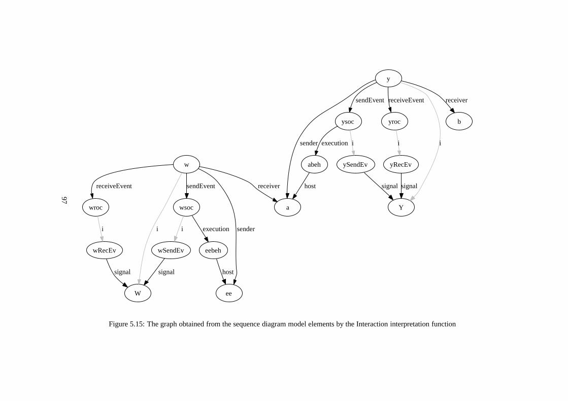
w
W
i
wsoc
sendEvent
wroc
receiveEvent
ee
sender
a
receiver
y
Y
i
ysoc
sendEvent
yroc
receiveEvent
sender
b
receiver
wSendEv
i
eebeh
execution
signal host
wRecEv
i
signal
ySendEv
i
abeh
execution
signalhost
yRecEv
i
signal
Figure 5.15: The graph obtained from the sequence diagram model elements by the Interaction interpretation function
97
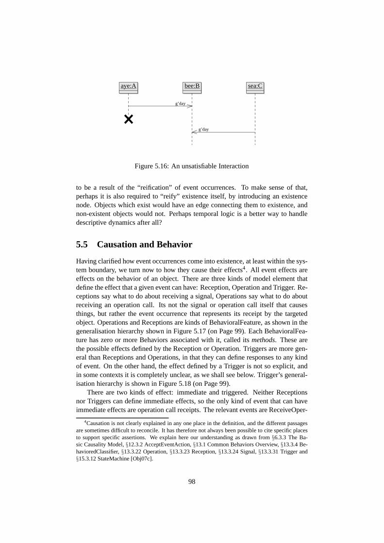
aye:A bee:B sea:C
g’day
g’day
Figure 5.16: An unsatisfiable Interaction
to be a result of the “reification” of event occurrences. To make sense of that,perhaps it is also required to “reify” existence itself, by introducing an existencenode. Objects which exist would have an edge connecting themto existence, andnon-existent objects would not. Perhaps temporal logic is abetter way to handledescriptive dynamics after all?
5.5 Causation and Behavior
Having clarified how event occurrences come into existence,at least within the sys-tem boundary, we turn now to how they cause their effects4. All event effects areeffects on the behavior of an object. There are three kinds ofmodel element thatdefine the effect that a given event can have: Reception, Operation and Trigger. Re-ceptions say what to do about receiving a signal, Operationssay what to do aboutreceiving an operation call. Its not the signal or operationcall itself that causesthings, but rather the event occurrence that represents itsreceipt by the targetedobject. Operations and Receptions are kinds of BehavioralFeature, as shown in thegeneralisation hierarchy shown in Figure 5.17 (on Page 99).Each BehavioralFea-ture has zero or more Behaviors associated with it, called its methods. These arethe possible effects defined by the Reception or Operation. Triggers are more gen-eral than Receptions and Operations, in that they can define responses to any kindof event. On the other hand, the effect defined by a Trigger is not so explicit, andin some contexts it is completely unclear, as we shall see below. Trigger’s general-isation hierarchy is shown in Figure 5.18 (on Page 99).
There are two kinds of effect: immediate and triggered. Neither Receptionsnor Triggers can define immediate effects, so the only kind ofevent that can haveimmediate effects are operation call receipts. The relevant events are ReceiveOper-
4Causation is not clearly explained in any one place in the definition, and the different passagesare sometimes difficult to reconcile. It has therefore not always been possible to cite specific placesto support specific assertions. We explain here our understanding as drawn from§6.3.3 The Ba-sic Causality Model,§12.3.2 AcceptEventAction,§13.1 Common Behaviors Overview,§13.3.4 Be-havioredClassifier,§13.3.22 Operation,§13.3.23 Reception,§13.3.24 Signal,§13.3.31 Trigger and§15.3.12 StateMachine [Obj07c].
98

Operation Reception
BehavioralFeature (from BasicBehaviors)
BehavioralFeature (from Kernel)
Feature Namespace
Figure 5.17: Generalisation hierarchies of Operation and Reception
NamedElement
Trigger
Figure 5.18: Generalisation hierarchy of Trigger
99

ationEvent and CallEvent [Obj07c,§14.3.27,§13.3.6]. These two Event types seemto be equivalent to one another, and also to the classes CallBehaviorOccurrence andCallOccurrence of the “domain model” [Obj07c, Figures 13.2, 13.4]. The effectof an operation call can only be immediate if the object has noTrigger for the rel-evant event occurrence [Obj07c,§13.3.22]. The effect is always invocation of aBehavior. An Operation is a BehavioralFeature of a Classifier. It can be associatedwith Behaviors (only in the§13.3.4 version, not the§7.3.5 one). How a behavioris chosen when the operation is called is a “semantic variation point”, to allow fordifferent kinds of late binding.
When an event occurrence arrives at an object and there is no immediate ef-fect, it is placed in the object’s “event pool”. As we discussed above, TimeEventsand ChangeEvents are not directed toward any specific object, yet have triggeredeffects. Its not clear whether these are placed in the pool ofall existing objects, orwhether the run-time mechanism is supposed to deliver them only where they arerelevant or exactly what is supposed to happen.
We are told that “operations specify immediate or triggeredeffects” [Obj07c,§13.3.22], but there is no way of specifying that a given operation has a triggeredeffect. Perhaps it means that operationshaveimmediate or triggered effects? Theoperation could decline to respond to the event immediately, allowing it to go intothe object’s event pool, and later handle it as a triggered effect. This conflicts withthe assertion that “a triggered effect is manifested by the storage of the occurrencein the input event pool of the object and the later consumption of the occurrence bythe execution of anongoingbehavior” [Obj07c,§13.3.4] (emphasis ours). Anotherpart of the definition describes the situation differently,making triggered operationinvocation a possibility: “[the event occurrence] is takenfrom the input pool andeither directly causes the occurrence of a behavior or [it is] delivered to the clas-sifier behavior of the receiving object for processing” [Obj07c, §13.3.31]. Someclarification of the definition is needed: can a behaviour be invoked as a triggeredeffect, or not?
Where Operations handle calls, Receptions handle Signals.Like Operations,Receptions are also a kind of BehavioralFeature. They can only produce “trig-gered” effects, since the notion of immediate effect is reserved for operations. Sig-nals are always asynchronous, but the triggered/immediatedistinction is indepen-dent of the synchronous/asynchronous one [Obj07c,§11.3.1]. There seems to beno principled reason why receipt of an asynchronous signal should not have an“immediate” effect, but that is how the language is defined.
So, Triggers and Receptions can only specify triggered effects. When one ofthese things handles an event occurrence, it is removed fromthe object’s eventpool, but as we discussed before, it continues to exist. If the object has no wayof handling the event occurrence, what happens to it is a semantic variation point[Obj07c,§13.3.4].
A Trigger can be part of a BehavioredClassifier, a Transitionor an AcceptEven-tAction. Trigger only has NamedElement as a superclass, as shown in Figure 5.18(on Page 99). Each Trigger is associated with one Event, which specifies the kind
100
of event occurrence it is looking for. “A trigger specifies anevent that may causethe execution of an associated behavior” [Obj07c,§13.3.31]. That is, a Behaviorassociated with the BehavioredClassifier or Transition which owns the Trigger. ABehavioredClassifier can own many Behaviors, so its not clear how the appropriatebehavior is selected. Although the definition does not say so, we presume it is a se-mantic variation point as we just discussed regarding the methods of an Operationor Reception. An AcceptEventAction is already within an Activity, which mustbe executing for it to accept an occurrence. They can be useful when the Activityneeds to receive a Request (signal or operation call) while it is running, and makeits contents available to the executing process.
A brief aside: there seems to be an anomaly with this action. AcceptEventAc-tion “cannot be used with synchronous calls” [Obj07c,§11.3.2, Semantics], andits specialisation AcceptCallAction [Obj07c,§11.3.1] cannot be used with asyn-chronous calls. But the only way of specifying what event occurrences they acceptis the Event linked to its Trigger, and none of the kinds of Event for specifying oper-ation call event occurrences have any way of distinguishingbetween synchronousand asynchronous calls. Perhaps the definition is suggesting that the run time ma-chinery will navigate from an event occurrence to the CallAction [Obj07c,§11.3.8]which originated it, and determine whether or not the call issynchronous, beforeaccepting or ignoring the call?
That is how causation works in UML. As we said earlier, every effect is aneffect on an object’s behavior, either initiating a behavior execution, or altering thecourse of an already executing behavior. In Section 5.3, we mentioned that Interac-tions are a kind of behavior, anemergentbehavior. The kinds of Behavior that canbe executed by an active object are Activities [Obj07c, Chapter 12] and StateMa-chines [Obj07c, Chapter 15]. Our small example actually hasboth of these: classA has a StateMachine, and the entry action of its states′ is an Activity. We discussthe state machine in the remainder of this section, and in thenext, we will examinethe entry action Activity.
In our example, the state machine diagram shown in Figure 5.2(on Page 81)is intended to define the behavior of classA in the class diagram of Figure 5.1(on Page 81). Class is a kind of BehavioredClassifier which has an associationclassifierBehaviorto its Behavior. The metamodel elements of the state machineinFigure 5.21 (on Page 104) shows this link betweenA and its state machine. Whilstthe ownedBehaviorsof a classifier are there to be invoked in various situations,executing its classifierBehavior is part of what makes an object an instance of itsclass. “When an instance of a behaviored classifier is created, its classifier behavioris invoked” [Obj07c, 13.2.4].
Figures 5.19 (on Page 103) and 5.20 (on Page 103) show the generalisationhierarchies of StateMachines and their main components. States and Transitionsare familiar concepts, similar to their origins in finite state automata, especiallywhen there are no “compound” states. One state is active, andwhen the Event onan outgoing Transition of the active state matches an event occurrence taken fromthe object’s pool, the state at the other end becomes the active one. There can be
101
entry and exit actions on the states, and actions on the transitions.Regions allow state machines, and their states to be dividedinto concurrently
executed parts. Our state machine has no concurrency, as it has only one region,and neither state contains a region. Generally, the “active” states of a state machineare a set conforming to the following rules: the state machine itself is active, eachregion immediately contained by an active state or state machine is active, andup to one of the states contained by an active region is active. The state machineitself can be seen as a tree with states and regions as nodes, alternating as we godeeper down the tree. The possible sets of active states of the state machine are thesubtrees that are “full” at the state nodes, and have no more than one child at eachregion node. Such a subtree is uniquely determined by its leaves, so this would bethe way to represent it in a graph:activeedges from the behavior execution nodeto the active leaf nodes of the state machine. In our example,eithersor s′ is active,or that neither state is active.
State machine regions can contain an initial “pseudo-state” with a single outgo-ing transition that has no trigger [Obj07c,§15.3.8]. Thus the real initial state of theregion is the target state of that transition. Our example has no initial pseudo-state,and we have not been able to find a statement in the definition about what willhappen when an execution of such a state machine begins. Perhaps it will haveno active state, and thus never do anything. Also, it is a mistake to assume thatevery item in the system state is there as a result of a UML defined creation pro-cess. Although object oriented software systems work this way, UML also modelsthe context of such a system. So for example an Actor may have astate machinedescribing its behavior, but we have no right to make any assumptions about whatstate we might find it in. Since UML is now applied beyond software, the sameargument applies to all model elements, as we saw in Section 4.2.
Returning to the model elements of our state machine in Figure 5.21 (on Page104), the Trigger of the Transition is connected to the same ReceiveSignalEventwhich forms part of the Interaction (sequence diagram), which is in turn, connectedto the Signalw. It is essential that we reuse this Signal rather than creating a newone, because signal instances will generally instantiate only one Signal, the oneassociated with the SendSignalAction that created it. Evenif we had two Signalsnamed “w”, they would generally have different instances. (As we discussed be-fore, it is possible for run-time entities to instantiate none or many model elements,for example when a ReclassifyObjectAction is applied.)
It seems unclear whether or not the Reception shown in Figure5.22 (on Page105) is needed. Reception’s semantics [Obj07c,§13.3.23] say that “the receiptof a signal instance by the instance of the classifier owning amatching receptionwill cause the asynchronousinvocationof the behavior specified as the method ofthe reception” (emphasis ours). We do not want to invoke the behavior, we wantthe occurrence to be processed by the behavior execution that is already running.However, the description of StateMachine [Obj07c,§15.3.12] says that “The be-haviored classifier context owning a state machine defines which signal and calltriggers are defined for the state machine, . . . . signal triggers and call triggers for
102

StateMachine
Behavior
Class
Region
Namespace RedefinableElement
Figure 5.19: Generalisation hierarchy of StateMachine andRegion
State
Namespace Vertex RedefinableElement
NamedElement
Transition
NamedElement
Figure 5.20: Generalisation hierarchies of State and Transition
the state machine are defined according to the receptions andoperations of thisclassifier.” The semantics of BehavioredClassifier [Obj07c, §13.3.4] does not givethe impression that anything extra is needed for behavior executions to find theoccurrences in the pool of their object, nor does the semantics of Trigger [Obj07c,§13.3.1], which says that “an event is dispatched when it is taken from the inputpool and either directly causes the occurrence of a behavioror are delivered to theclassifier behavior of the receiving object for processing”.
The meaning that the definition gives to our state machine is now as clear aswe can make it, except for the entry action of states′. This will be the subject ofour next section. We have found a few more problems with the existing definition.It is unclear whether or not operation invocation can be a triggered effect, nor isit clear whether or not a Reception is needed to transfer event occurrences to aStateMachines Trigger. Different parts of the definition take different points ofview.
103

s:State
name = ‘‘s’’isLeaf = false/isComposite = false/isOrthogonal = false/isSimple = true/isSubmachineState = false
s’:State
name = ‘‘s’’’isLeaf = false/isComposite = false/isOrthogonal = false/isSimple = true/isSubmachineState = false
s_W_s’:Transition
kind = internalisLeaf = false
:Trigger w_rec_event:ReceiveSignalEvent w:Signal
smAreg:Region
isLeaf = false
sm_A:StateMachine
visibility = publicisLeaf = falseisAbstract = falseisReentrant = true
A:Class
event signal
trigger
ownedElementtransition
ownercontainer
source outgoing
subvertexownedMember
containernamespace
targetincoming
subvertexownedMember
containernamespace
regionownedMember
stateMachinenamespace
classifierBehaviorownedBehaviorownedMember
memberownedElement
contextredefinitionContext
Figure 5.21: Metamodel elements of the state machine diagram
104
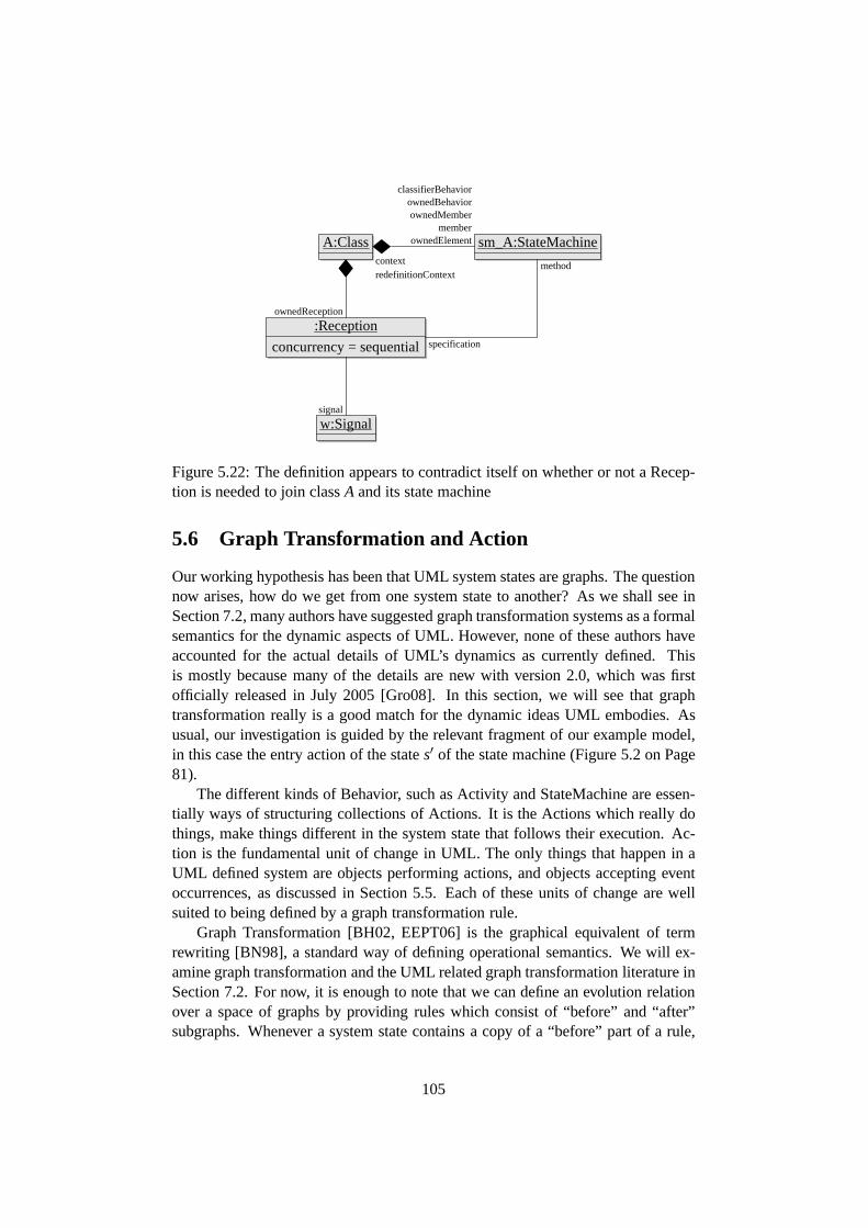
A:Class
:Reception
concurrency = sequential
sm_A:StateMachine
w:Signal
ownedReception
signal
classifierBehaviorownedBehaviorownedMember
memberownedElement
contextredefinitionContext
method
specification
Figure 5.22: The definition appears to contradict itself on whether or not a Recep-tion is needed to join classA and its state machine
5.6 Graph Transformation and Action
Our working hypothesis has been that UML system states are graphs. The questionnow arises, how do we get from one system state to another? As we shall see inSection 7.2, many authors have suggested graph transformation systems as a formalsemantics for the dynamic aspects of UML. However, none of these authors haveaccounted for the actual details of UML’s dynamics as currently defined. Thisis mostly because many of the details are new with version 2.0, which was firstofficially released in July 2005 [Gro08]. In this section, wewill see that graphtransformation really is a good match for the dynamic ideas UML embodies. Asusual, our investigation is guided by the relevant fragmentof our example model,in this case the entry action of the states′ of the state machine (Figure 5.2 on Page81).
The different kinds of Behavior, such as Activity and StateMachine are essen-tially ways of structuring collections of Actions. It is theActions which really dothings, make things different in the system state that follows their execution. Ac-tion is the fundamental unit of change in UML. The only thingsthat happen in aUML defined system are objects performing actions, and objects accepting eventoccurrences, as discussed in Section 5.5. Each of these units of change are wellsuited to being defined by a graph transformation rule.
Graph Transformation [BH02, EEPT06] is the graphical equivalent of termrewriting [BN98], a standard way of defining operational semantics. We will ex-amine graph transformation and the UML related graph transformation literature inSection 7.2. For now, it is enough to note that we can define an evolution relationover a space of graphs by providing rules which consist of “before” and “after”subgraphs. Whenever a system state contains a copy of a “before” part of a rule,
105

Behavior
Activity
Figure 5.23: Generalisation hierarchy of Activity
we can replace it with the “after” part, and obtain a valid successor state. As weexamine the metamodel elements of our example action, we will consider whatkind of graph transformation rules will be required to realise it.
We turn now to the specific example before us, and the meaning of the modelelements it comprises. The generalisation hierarchy of Activity is shown in Figure5.23 (on Page 106). The metamodel elements of the entry action of states′ of ourexample are shown in Figure 5.24 (on Page 107).
A behavior execution in the system state will need to record its progress inmuch the way the instruction pointer register of a CPU does, or the program counterof a virtual address space. The control structures are described in [Obj07c, Chapter12], and are defined in terms of “tokens” being passed from oneActivityNode toanother. Actions also have data requirements. When the control and data require-ments for an action are satisfied it is “enabled” and may be executed. The obviousway to do these things in a system state graph is to have one or more speciallynamed edges from the execution to the next Action or Actions to perform. Thegraph transformation rules which perform the actions will also be responsible forupdating these “enabled” edges.
The flow of data between the Actions in a Behavior is mediated by Pins [Obj07c,§11.3.28,§12.3.44]. Pins are temporary storage areas where one actioncan leavesome values for another action to use. They have a type, and a multiplicity, as thespecialisation hierarchy shows in Figure 5.25 (on Page 108). Actions wait until therequired number of values are available on their input Pins.This required numberis given by the lower bound. Since all the upper and lower bounds of pins in ourexample are 1, we have not shown the upper and lower bound objects in Figure5.24 (on Page 107) as we did in the class diagram model elements diagram 5.8 (onPage 86).
Recall the discussion in Chapter 3 of the core metamodel fragment shown inFigure 3.2 (on Page 36). This fragment has classes Property and Classifier and twoassociations between them, classifier and type. We noted that this fragment resem-bles the category theoretic diagram which defines graphs. Wehave an analogoussituation here with Pins and Behaviors. Because Pin is a kindof TypedElement,each Pin has atypewhich is a Classifier. Each Pin also belongs, perhaps transi-tively, to an Activity, which is a kind of Behavior and hence aClassifier. In Chapter
106
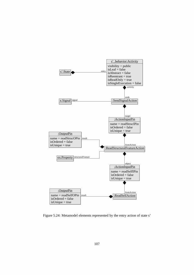
s’:State
s’_behavior:Activity
visibility = publicisLeaf = falseisAbstract = falseisReentrant = trueisReadOnly = trueisSingleExecution = false
:SendSignalActionx:Signal
:ActionInputPin
name = readStrucIPinisOrdered = falseisUnique = true
:OutputPin
name = readStrucOPinisOrdered = falseisUnique = true
:ReadStructuralFeatureAction
ex:Property
:ActionInputPin
name = readSelfIPinisOrdered = falseisUnique = true
:OutputPin
name = readSelfOPinisOrdered = falseisUnique = true
:ReadSelfAction
entry
node
activity
signal
target
fromAction
result
structuralFeature
object
fromActionresult
Figure 5.24: Metamodel elements represented by the entry action of state s’
107

Pin
TypedElement MultiplicityElement
Figure 5.25: Generalisation hierarchy of Pin
3, we converted the model graph with properties as nodes intoa type graph withproperties as edges. The equivalent move here is to turn the Pins into labellededges, so that valid run-time states will have edges from behavior executions totheir pin-values, labelled by the pins name. We shall adopt this as a working hy-pothesis of run-time pin values.
A difficulty with this proposal is that, as a Classifier, Behaviors can have Prop-erties, and a Property might have the same name as one of the Behaviors Pins. Ifa behavior execution has an outgoing edgep to some valuev, there will be no wayof knowing whetherv is on the pinp or the propertyp. This is not much worsethan a difficulty already present in the graph treatment. A classifier can have twoor more Properties with the same name. An outgoing edge labelled with this namemight belong to either of them. A ReadStructuralFeatureAction associated withone of these Properties would return values that are meant tobelong to the other.One option would be to label the edges with the Property or Pinitself, ie the valuewhich is the node in the model graph?
Let us consider the Actions that make up the example Activity. Recall that itcan be expressed textually assend X to self.ex . The “innermost” part ofthis command, the part that must be evaluated first, isself , which is representedin the Activity as a ReadSelfAction [Obj07c,§11.3.36]. Assuming that all pininstances are empty when a behavior execution begins (the definition does not say),this is the only Action which can be executed immediately, asit is the only onewith no input pin. “When the behavior executes, it does so in the context of somespecific host instance of that classifier. This action [ReadSelfAction] produces thishost instance, if any, on its output pin” [Obj07c,§11.3.36].
An ActionInputPin takes the values on the output pin of an action and providesthem as input to another action. If we realise values being onpins by edges labelledwith the pin name, then an ActionInputPin should cause theseedges to be createdin pairs. Whenever a value is added to the output pin of the fromAction of anActionInputPin, it should also be added to the ActionInputPin. In our example,when the context objecta is put on the output pin of the ReadSelfAction by addinga “readSelfOPin” labelled edge from the behavior execution toa, a “readSelfIPin”labelled edge should also be added there.
Once this has happened, the ReadStructuralFeatureAction will be enabled. The
108

other parameter of this action is the Property “ex”, which we saw before in themodel elements from the class diagram, in Figure 5.8 (on Page86). We discussedand defined ReadStructuralFeatureAction in Chapter 4. There, we determined thateach Property in a reflective system state denotes a functionfrom the instances ofits classifier to a collection of values of its type. The ReadStructuralFeatureActionevaluates this function for its Property and the instance onits input pin, and placesthe resulting value on its output pin. The multiplicities ofthe propertyex and ofpin are both 1, so in this example there is no problem about thenumber of valueson the pin. But what happens if the number of results is more than the upper boundof the output pin? “An action may not put more values in an output pin in a singleexecution than the upper multiplicity of the pin” [Obj07c,§11.3.27]. Perhaps anarbitrary selection is made, or it is considered to be a run-time error?
The input parameters to the SendSignalAction then are the (one and only)exofthe object executing this action, which it will find on the pin, and the Signalx. ThisSignal does not occur in the Interaction model elements in Figure 5.13 (on Page94). Execution of the SendSignalAction will result in a new instance of Signalxbeing created. According to our interpretation of the run-time “domain model” of[Obj07c, Figure 13.3], it will have an outgoing edge labelled “sender” to the objecta, and one labelled “receiver” to the objectb. A separate rule will add the receiveevent occurrence and its edges,messageto thex signal instance, and apool edgeinto it from b. This creates the possibility of a delay between sending andreceiptof a signal, as required by the UML run-time definition.
We now have a fairly clear idea of the system states that our example modelwill have during its possible executions. Graph transformation rules seem a goodcandidate for a way of defining this precisely. Another example of the graph-defining graph has emerged with Behaviors and their Pins. We now turn to the taskof this Chapter, to determine whether or not the model is consistent.
5.7 Consistency
The previous sections of this chapter have studied the individual model elementsof our example model. Now it is time to put what we have learnedtogether, andask whether the model is consistent. We shall first establishjust what that means,and uncover some more difficulties overlooked in the officialdefinition.
In Section 5.4 we determined that an Interaction (sequence diagram) is satis-fied by a system state in much the same way as an object diagram is. Because thesystem state contains its own history, we do not need to consider a sequence of sys-tem states, just one state from after when the described happenings are complete,but before any of the participants have been deleted. As we observed, this is notpossible for some sequence diagrams containing DestructionEvents.
The graph in Figure 5.15 (on Page 97), which we obtained from the Interactionand the elements linked to it, is a picture of the history we expect to find in the sys-tem state. In Section 3.6 when considering the semantics of InstanceSpecifications
109

and Slots (object diagrams), we determined that the homomorphism that maps thegraph obtained from these elements into the system state must map any Classifiersto themselves. Otherwise, the InstanceSpecifications might refer to objects of thewrong Class. The same constraint must apply to the interaction graph.
The “initial” state of a system could contain objects, linksand behavior execu-tions, but should not contain event occurrences. Allowing this would be equivalentto the implausible situation described by Bertrand Russellin response to creationistclaims that God created the earth complete with buried dinosaur skeletons: “Thereis no logical impossibility in the hypothesis that the worldsprang into being fiveminutes ago, exactly as it then was, with a population that “remembered” a whollyunreal past” [Rus21]. In the case of our example model, allowing “pre-existing”event occurrences would make its consistency trivial, we would only need to con-struct a system state that contains the graph shown in Figure5.15. Whether or notthe described events can actually happen would be beside thepoint. We thereforefurther restrict the valid UML system states to those that either contain no eventoccurrences, or are derived from such a state by valid systemevolution. That is,we prohibit the system state from having an unreal past.
What we are attempting to find then, is an initial state, and a sequence ofsystem-state transitions which will result in a system state containing the inter-action graph of Figure 5.15 as a subgraph, perhaps with some renaming.
The required initial state will have objectsee, a andb. Lifeline does not specifythe Classifier(s) of the objects they represent, so they may or may not instantiateClassifiersEE, A andB respectively as we intend. In Section 3.5 we determinedthat the model must be present in each system state, so these Classifiers will bepresent, along with the send and receive signal event elements from the Interaction.
We have discussed the creation of event occurrences, but only where they orig-inate from inside the system. But not all events are generated by objects withinthe system. “Events are often generated as a result of some action either withinthe system or in the environment surrounding the system.” [Obj07c, §13.3.31].Unfortunately, this passage does not go on to give details. The Actor in our ex-ample sequence diagram is intended to represent someone or something outsidethe system boundary. Although she is outside the system boundary, we distinguishher from the remainder of the system environment. If we were content to treat thesystem context as an undifferentiated whole, we would dispense with the Actor.The signal could just appear as a “found message” [Obj07c,§14.3.20] which is re-ceived, but never sent5! This would be compatible with Mellor’s original example,since he does not specify what caused the first object to emit its signal. We preferto try to make sense of our formulation however, since Actorsare a part of UML,and intended to be used in this way.
Actor is a kind of BehavioredClassifier, so it can have state-machines and ac-tivities. Indeed, it appears that our Actor must have a behavior, because it is in-tended to send a message. The send message event occurrence would instantiate
5This would violate the multiplicities of the system-state domain model [Obj07c, Figure 13.3]
110

InvocationOccurrence in the definitions system-state domain model [Obj07c, Fig-ure 13.3], and Each of these is linked to exactly one behaviorexecution. How dowe reconcile prescribing the behavior of an element with thefact that that elementrepresents an entity that is not controlled by the system? One solution is to givethe Actor an OpaqueBehavior. The semantics of OpaqueBehavior is “determinedby the implementation” [Obj07c,§13.3.20], which is to say, it could do anything.
This would seem to make the model’s consistency a trivial question. If thebehavior can do anything, then anything can happen, so the story told by the se-quence diagram can happen, so the model is consistent. What we want is to de-scribe a range of possible behaviors for the Actor. Because of the parallel, non-deterministic execution model of UML’s Activities, this may be possible. It isnot obvious how to define the range of possible recipients of SendSignalActionsthough. We could solve that problem for our example by assuming that a link ex-ists in the initial state between the Actoreeand the objecta. This leaves the generalproblem of specifying a limited range of possible actions for Actors.
We assume that in the initial state, the external entityee is already executingan opaque behavioreebeh. This behavior adds the Signal instancew to the systemstate, along with its send event occurrencewsoc. If this non-deterministic behaviorcan be properly defined in UML, then the graph transformationrules will follow,but if it needs to be an OpaqueBehavior, then some kind of wild-card rule will berequired. The outgoing instantiation, sender, receiver, sendEvent edges will alsobe added at this point.
A separate rule will add the receive event occurrencewroc and its edges. Thiscreates the possibility of a delay between sending and receipt of a signal, as re-quired by the UML run-time definition. An edge labelledpool will connecta tothis occurrence, indicating that it is ina’s event pool.
The presence of this occurrence ina’s event pool will enable a match withthe left-hand-side of an event acceptance rule, which must also match many otheraspects of the system state. There will need to be three versions of this rule, one foreach of the possible effect defining elements: Reception, Operation and Trigger.Recall that there is some doubt about the meaning of Reception, and it remainsunclear whether classA should have a Reception for SignalW. The Trigger formof the rule may need its own variants to deal with the different roles a Trigger canplay. So, a Transition Trigger form of the accept event occurrence rule will matchthe objecta and the event occurrencewroc and thepool edge between them. Theactivelink from a to the origin stateSof this Trigger will also occur in the left handside of this rule. The Trigger is connected to the Signal, andthe event occurrenceis also, via its instantiation ofwRecEv, the receive signal Event. The right handside of the rule will omit thepool link, will have theactive link moved from thesource to the target state of the Transition. This rule will also need to create anynew behavior executions for the exit action of the source state, the effect of theTransition, and the entry action of the target state. Indeedfor nested states, thebehavior invocation story is even more involved [Obj07c,§15.3.11, State].
After this rule has been applied, there will be a new execution of the Activity
111

which is the entry action of states′. It will be hosted byb, and each of its actionswill be processed by a graph transformation rule dedicated to that Action, main-taining pin value edges as described earlier. When it reaches the SendSignalAction,the resulting signal node will instantiate SignalX, not Y, becauseX is thesignallinked to that action.
In the early phases of development, UML models are not intended to describeevery detail of their target system. Thus valid interpretations should be allowed tocontain items not described by the model. If such an object received aw messagefrom eeand sent aY message tob, then it can play the role ofa in the interaction,and it is thus satisfied. For that to happen, the object would have to instantiate aclassifier with a behavior which would make it send the message. We tentativelydefined the valid states of a given model to be those that contain the model, andhave certain homomorphisms to and from various interpretations. This allows themodel in the system state to be a superset of the one specified.
Although this relaxed view has its uses, perhaps in later stages of development,and in particular when checking sequence diagrams, we should be stricter aboutwhat is permitted in the system state. We could exclude non-model classes byinsisting that(P ◦ γ)(ss) = (P ◦ γ)(m), wherem is the model,ssthe system stateand(P ◦ γ) is the class model interpretation function from Chapter 3. Let’s addthis constraint to the admissible system states.
Now, because the map from the interaction graph to the systemstate graph
must preserve classifiers, the edgey i // Y will have nothing to map to. Therecan not have been anyY instances in the initial state, because each request musthave a send and receive event occurrence [Obj07c, Figure 13.3], but we requiredthat the initial state had no event occurrences. There is no classifier in the modelthat has a behavior which can produce aY signal.
We conclude then that, contrary to Stephen Mellor’s claim, the model is incon-sistent, provided that the model is seen as complete, ie thatthe system containsno other classifiers. We have encountered much that is unclear and difficult in theUML definition, and our conclusion depends on some kind of resolution to theseissues. We summarise them here for completeness.
1. There are many problems regarding “emergent behavior” such as Interac-tions:
• Valid system states should only have real history recorded in them.
• Many intuitively sensible interactions are unsatisfiable because of the“event rot” problem.
• The definitions “trace” semantics for Interactions is an unnecessarycomplication. Our graph homomorphism approach is equivalent andmuch simpler. (However, the whole “recorded-history” approach todescriptive dynamics is flawed and probably should be replaced by atemporal logic approach.)
112

• Emergent behaviors are really quite different to other Behaviors. Itshould not be a kind of classifier, because the status of partially com-pleted executions is ambiguous.
2. Is a triggered effect always accomplished by an ongoing process consumingthe event occurrence, or can operation invocation be a triggered effect?
3. Is a Reception needed for a classifier’s behaviors to handle its signals?
4. The partial and complete views of the model’s specification of the systemshould be addressed in the definition. This is a global semantic variation.
5. Event occurrences such as TimeEvents, which are not directed toward spe-cific objects, need to have their effect’s process defined. Does every UMLsystem state contain infinitely many such event occurrences?
6. The selection of a method for Receptions and Triggers owned by classifiersneeds to be defined, or explicitly made a semantic variation point.
7. ExecutionEvents are extremely general. This could lead to unintended satis-faction of Interactions and Triggers.
8. There should be some observable distinction between synchronous and asyn-chronous call requests.
9. What happens when an action produces too many results for its output pin?
10. When a behavior is invoked, all the pins of the new behavior executionshould be empty.
11. We require a way of defining a wide, but not unlimited rangeof possiblebehavior for Actors.
Although we have concluded that there really is a useful meaning to UMLmodels, it is certainly not easy to determine this from the definition. There wouldbe scope for other readers to disagree with the meaning we have extracted. Ourgraph hypothesis has been helpful to clarify things, and we do not believe that ithas added meaning where there really is none.
In Chapter 1, we set ourselves the task of solving the UML “definition prob-lem”. Perhaps the most important conclusion to draw from thepresent Chapter isthat this task makes sense: there really is something to define, and it really is notvery well defined at the moment.
Since the graph hypothesis has helped us to explain all we have encountered inUML, we propose that a definition be written directly in termsof graphs. Workingsoftware developers are notoriously averse to anything that looks mathematical.However, the required background is easily within reach of undergraduate discretemathematics courses. It is no more difficult than the relational material covered
113

in any worthwhile university database course. We compare the state of databasetheory with that of UML in Section 7.1, and find that the relational model is anexample UML should aspire to. The proposed definition document would need afew pages of introduction to graphs and graph transformations. The cost of eachattempt to extract meaning from the current definition is quite unreasonable. Webelieve that the investment asked of a reader in reading the introduction to graphswould be returned many-fold each time she attempted to determine the meaning ofa given modelling construct.
114
Chapter 6
Dynamic Logic for UMLConsistency
In Chapter 5 we concluded that the current UML definition [Obj07c] does defineits semantics sufficiently to declare the tiny example modelof Section 5.1 incon-sistent. There were many provisos to this conclusion, and many ways in which theclarity of the definition needed improving. We also found several serious difficul-ties with a rather fundamental aspect of UML, its descriptive dynamics.
Each UML system state records its history as event occurrences which arelinked to one another and the things they happened to. Interactions (sequence dia-grams) describe these configurations of recorded history. In fact, they are definedas an “emergent behavior” and actually specialise Behaviorand thus Classifier, andshould therefore have instances. The best sense we could make of that is that therecorded history subgraph is the “instance”, which only exists after the describedoccurrences have happened. The most serious flaw in this scheme is that if some ofthe participants cease to exist, the recorded history can not match the descriptiongiven by the Interaction. Therefore, Interactions that describe destruction eventsfollowed by something else are unsatisfiable. We called thisthe “event rot” bug.
We proposed that descriptive dynamics would be better handled by a temporallogic1. Although the task of this study is to define the existing language better, thisChapter explicitly exceeds that scope to consider modifications to UML itself.
The main part of this chapter is work we completed about212 years ago, before
we recognised the deep parallels between UML and graph transformation. Its goalwas to make UML precise by translating its diagrams into dynamic logic [HKT00].It does not consider the official UML definition, rather it treats the fragment usedin the Executable UML technique [MB02], and follows its conventions. The workwas published as [O’K06a]. Although classical dynamic logic for UML semanticsno longer seems like a good idea, there is value we believe in its approach todescriptive dynamics. We present the work in close to its original form, then in
1By this we mean any modal logic whose modalities represent the passage of time, not only thoselogics with binary “until” operators.
115

a concluding postscript section, consider whether descriptive dynamics would bebetter defined using this approach, and how it might fit in withthe remainder of thelanguage.
The first section briefly introduces dynamic logic. In the following section wesystematically translate each diagram of the example modelfrom Section 5.1 intodynamic logic formulae. A system specification is then formed using these diagramformulae as subterms. We then search for a trace which satisfies this specificationand establish that none exists.
6.1 Dynamic Logic
In this section we briefly introduce logic, beginning with simple propositionallogic. Then we consider two different extensions: modal logics and first orderlogic. Finally, we combine these extensions and obtain the form of dynamic logicwe need to complete our formalisation.
A logic consists of syntax, semantics and a deductive calculus. The syntaxdefines a set of formulae, which we call the language of the logic. The formulae arejust symbolised statements. The semantics defines a range ofpossible situations,each of which assigns eithertrue or false to each formula of the language. If asituationw makes a formulaϕ true, we writew |= ϕ, and, confusingly for UMLpeople, say thatw modelsϕ. We say thatϕ is a semantic consequence of a set offormulaeΓ, if ϕ is true in every situation that makes all the formulae inΓ true. Wealso writeΓ |= ϕ whenϕ is a semantic consequence ofΓ. A deductive calculusdefines proofs, each of which derives a formula from some set of formulae. If aproof exists derivingϕ from Γ we writeΓ ⊢ ϕ. We wantΓ |= ϕ wheneverΓ ⊢ ϕ,so that deduction can be used to establish semantic consequence. We will not saymuch more about deduction.
Propositional logic has atomic formulaeP,Q,R, . . . and ifϕ andψ are formu-lae, then so are¬ ϕ, ϕ ∨ ψ, ϕ ∧ ψ andϕ // ψ. These symbols stand for not, or,and, and if . . . then . . . respectively. The possible situations of propositional seman-tics are functions from the atomic formulae to the truth values{true, false}. Wewill call these functions propositional interpretations.These are extended to thewhole language by assigning each of the connectives¬ ,∨,∧, // the obvioustruth function. We write⊤ as a formula that is always true, and⊥ for one which isalways false.
Propositional modal logics add some one-place connectives. Typically we addto the above syntactic rules that ifϕ is a formula, then so are�ϕ and3ϕ . Someintuitive interpretations of these connectives are: necessarily and possibly, alwaysand sometimes, obligatory and permissible. We are interested in temporal interpre-tations, where�ϕ means thatϕ is true at all possible future situations, and3ϕ istrue in some possible future situation. Semantics for a propositional modal logicare given by introducing a binary relationR between the propositional interpreta-tions. Then�ϕ is true atw if ϕ is true at every situationR-related tow, and3ϕ
116

is true atw if ϕ is true at some situationR-related tow. So for example, we mightthink of the relation as representing time, so thatw1Rw2 if our system can evolvefrom situationw1 to situationw2. Using the relation, the semantics are extendedto formulae with� and3 as follows: w1 |= 3ϕ iff w2 |= ϕ for somew2 wherew1Rw2, andw2 |= �ϕ iff w2 |= ϕ for everyw2 wherew1Rw2.
This is already a useful formal language, because ifR captures the possibleevolution of a system, and we have formulaeInit and Bad which represent theacceptable initial states of the system, and undesirable situations respectively, thenthe formulaInit // ¬ 3Bad is true if and only if it is impossible for the systemto evolve from an acceptable initial state into an undesirable situation.
Propositional dynamic logicPDL has a pair of modal operators for each pro-gram in a simple programming language. There are atomic programs,α, β, γ, . . .and if ρ andσ are programs then so areρ; σ, ρ ∪ σ andρ∗. These are the regularexpressions over the atomic programs. Also, ifϕ is a formula, thenϕ? is a pro-gram. Each atomic program denotes a relation over the situations,ρ∪σ denotes theunion of the two relations (non-deterministic choice) andρ∗ denotes the reflexivetransitive closure of the relation denoted byρ (non-deterministic repetition). Theprogramϕ? denotes the relation{(w,w) | w |= ϕ} which relates a situation toitself whenϕ is true there. This can be used to place guards on programs, and towrite conditionals, such as(ϕ?; α) ∪ (¬ ϕ?; β) for if ϕ then α else β.In propositional modal logic, the semantics for the modal operators� and3 weregiven using a binary relation. In propositional dynamic logic, each programρ cor-responds to a binary relation, and the semantics of the modaloperators[ρ] and〈ρ〉depend on this relation. Note the use of the angle and square brackets to resemblethe diamond and square operators.
We can write for example〈α〉⊤, to mean that the programα runs successfully(terminates), or〈α〉⊤ // ϕ to mean thatα only runs successfully in situationssatisfyingϕ.
Although we work with full first order dynamic logicDL in this paper, it islikely that models could be usefully approximated byPDL. This could be enableautomated tools, asPDL is decidable [HKT00, Chapter 6], whereasDL, since itproperly extends first order logic, is not.
First order logic also extends propositional logic. Where the basic formulae ofpropositional logic are unanalysed propositionsP,Q etc, first order logic formulaeassert properties of individuals or assert relationships between individuals. Forexample, a two place relation symbolL might be interpreted as “. . . loves . . . ” thenamea might mean “Aaron” andb “Belinda” thenLab would be read as “Aaronloves Belinda.” The logic includes equality, so we may writea = b meaning“Aaron is Belinda.” Names are one kind ofterm, that is expressions which referto an individual. Variablesx, y, z, . . . are another kind of term, and terms can beformed by applyingn-place function symbols,f ,g, . . . to n terms, forn = 1, 2, . . ..For example if the 1-place function symbolf is read as “the father of . . . ,” thenLxf(b) should be read as “x loves Belinda’s father.” First order logic also hasquantifiers∀ and∃ so that(∀ x)Lxf(b) means everybody loves Belinda’s father,
117
and(∃ x)Lxf(b) that somebody does.The semantic situations for first order logic (which logicians call “models”)
consist of a set of individuals, called the semanticdomain, and aninterpretationwhich takes each name to an individual and eachn-place relation/function symbolto an-place relation/function. To evaluate variables and quantifiers, we also needa valuation. This takes each variable to an individual in the semantic domain.The formal definition of truth of a formula in an interpretation just says that, inthe interpretation, things are as the formula says they are.The frightening notationrequired to state this precisely is unhelpful in the currentcontext (horror enthusiastsare referred to [Hod97,§2.1]).
The semantics of quantified formulae are defined using the idea of variantsofthe valuation. Anx variant ofw is a valuation that is the same asw for all inputsexcept forx. This is worth explaining, because we will use these ideas again soon.We introduce some notation for a function the same asw, except that it takesx toq. Definew⊕ x 7→ q by
(w⊕ x 7→ q)(y) =
{
q if x = yw(y) otherwise
ThenM,w |= (∃ x)ϕ(x) iff M, (w⊕x 7→ q) |= ϕ(x) for someq, and similarly for∀ formulae. Then∃ x, ϕ(x) is satisfied by the model and valuationM,w iff ϕ(x) issatisfied byM, (w⊕ x 7→ q) for someq. And similarly for∀ formulae.
The language of dynamic logic includes that of first order logic plus modaloperators similar to those ofPDL. The atomic programs ofDL are assignments ofthe formx := t for some variablex and some termt. Programs are formed fromatomic programs, using∪, ;, and∗, and from formulae using?, just like in PDL,and the meanings of these connectives are also the same here.Thus to completethe semantics ofDL we need to define the relation denoted by each assignmentstatement. The situations that make our formulae true or false are model, valuationpairsM,w. Intuitively, assigning a new value to a variable changes the valuation,but does not change the interpretation. So, for each interpretationM, the atomicprogramx := t relates each valuationw to w ⊕ x 7→ tM,w, wheretM,w is thevalue of the termt under the interpretationM and valuationw. For example, theformulaa = 5 // 〈x := a〉x = 5, says that ifa = 5 then after you setx to a, yougetx = 5. This is always true, because ifa = 5 inM,w, that isaM,w = 5, thenx = 5 inM, (w⊕ x 7→ aM,w).
Our objective is to reason about object oriented systems, where objects retaintheir identity over time, but have attributes whose values may change. So far,we have only seen how to make variables change over time. We could make thevariables denote records, but this leads to object aliasingproblems [CIO00]. Ifx andy denote the same object, then changes tox should result in changes toy,but without special tricks (eg [Bec01]), logics do not do this. A better way is tohave object identifiers as individuals, and object attributes as functions, so that thefamiliar o.a notation becomes short-hand fora(o). Then what we want is the abilityto update these functions. An extension of dynamic logic studied in [HKT00]
118
allows such updateable functions, called array variables.Indeed, a similar systemhas been used to formalise parts of UML 1.1 in [WB97] (Discussed in Section 7.3).Weiringa’s logic has ordered sorts too, to cater for specialisation
The syntax ofDL is extended byn-place array variables for eachn = 1, 2, . . ..These can occur wherever ann-place function symbol can occur, but also on the lefthand side of an assignment statement. We are mostly interested in 1-place arrayvariables. We will use the attribute access dot notation when the array variablerepresents an attribute, so an assignment has the formt.h := s or h(t) := s fortermst, s and 1-place array variable h. The semantics are adapted so that now thevaluations also assign ann-place function to eachn-place array variable. For afixed modelM, this assignment denotes a relation that relates each valuation w tow⊕ h 7→ (hw ⊕ tM,w 7→ sM,w). That is,w is related to an updated form ofw,which maps the array variableh to the same functionw maps it to, except updatedso that it sends the value oft to the value ofs.
This is the form of dynamic logic that we use to precisely express our interpre-tations of the UML diagrams and actions.
6.2 The Model as Dynamic Logic Formulae
How can we represent this model using formulae of dynamic logic? We begin thissection with some general considerations about the relationship between dynamiclogic and the small UML subset used for this model. In each of the followingsubsections, we will discuss one of the diagrams, and give its meaning as a dynamiclogic formula. These meanings are influenced by the use made of the diagrams inthe Executable UML [MB02] method. In the next section we willcombine theclass diagram, state machine diagram and action formulae tospecify the system,and then show that this specification is inconsistent with the sequence diagramformula.
We give rather weak interpretations of each diagram, for example, assumingthat there might be objects in the system that do not belong toany class on theclass diagram. These interpretations are debatable, indeed it is possible that theweak interpretations are more appropriate in an analysis phase, whilst strongerones might serve the design phase better. Indeed, we may wantto keep severalinterpretations available to cater for UML’s numerous “semantic variation points.”The particular interpretations are not the main point though. Rather we aim todemonstrate that dynamic logic provides a simple and usefulway of giving themeanings of the diagrams. The reader should not overlook another important virtueof the weak interpretations: they are shorter!
System Snapshots and Evolution
In Section 6.1 we said that the possible situations of the semantics of dynamiclogic consist of an interpretation and a valuation. The interpretation gives meaning
119

to the fixed vocabulary such as names, relation symbols and function symbols.In the UML context, the functions and relations will mostly come from the OCLlibrary, or perhaps an action language library. These can beconsidered to be fixedonce and for all (though who knows what future versions of UMLwill bring?)If the interpretation was fixed throughout our work, that would be good, becausewe could essentially forget about it and only think about thevaluations. For thisreason, we will consider all model specific vocabulary to be variables, evaluatedby the valuation, while the interpretation takes care of theglobal UML vocabularysuch as OCL library functions. The valuation tells us about aparticular systemat a particular point in time. Hence, a system snapshot is a valuation, and theinterpretation can be largely ignored, because it is fixed.
EachDL program relates pairs of these snapshots, but not everyDL programcorresponds to a legal evolution of the system. What we need is a formal definitionof legal evolution. So, what can happen in a system defined by our subset of UML?Only two things really: objects can send messages, and they can accept them.There are conditions though, an object can only send a message if that action isat the head of its todo list2, although an external entity can send whatever it wantswhenever it wants. An object can only accept a message if it has a message toaccept, and it is not currently activated. The non-deterministic DL programεwhichdescribes how these systems can evolve is defined as follows.
ε ≡ ((sendCond(x,M, y)?; x.send M to y) ∪ (acceptCond(x)?; x.accept))∗
wheresendCond(x,M, y) is a formula, defined below, stating the conditions underwhich it is OK for x to send anM message toy, send M to y is aDL program,also defined below, which does what the send action is meant todo, and similarlyfor acceptCondandaccept .
sendCond(x,M, y) ≡ class(x) = EE∨ (head(todo(x)) = send M to y)
acceptCond(x) ≡ todo(x) = () ∧ size(intray(x)) > 0
whereheadandsizeare library functions with the obvious meaning, andtodoandintray are array variables used to represent an object’s outstanding actions andmessages respectively. The special class nameEE is introduced so that externalentities can be treated as objects having this class.
Note thattodo takes objects to programs, which on the face of it is a categoryerror, because programs are part of the syntax, not individuals in the semanticdomain. By adding function symbols corresponding to∗, :=,∪ and; , we can copythe program language into the semantic domain. Whenever yousee a program onthe right hand side of an equals sign, it is shorthand for a term formed using thisvocabulary.
2We make some assumptions about action scheduling and event pool ordering, as suggested bythe terms “todo list” and “intray”
120
Now we define the actionssend and accept . When an objectx sends amessageM to the objecty, the message is placed iny’s intray, and thesend actionis removed fromx’s todo list.
x.send M to y ≡intray(y) := append(intray(y),M);todo(x) := tail(todo(x))
whereappendandtail are library functions.When an object accepts a message, it makes the state transition specified in its
state machine, loads the entry procedure of the new state, and removes the messagefrom its intray.
x.accept ≡state(x) := nextState(state(x), head(intray(x)));todo(x) := entryProc(state(x));intray(x) := tail(intray(x))
Wherestate is an array variable used to record an object’s state. This definitiondepends on the functionsnextStateandentryProc, which in turn depend on the statemachine diagrams of the model. The definitions of these functions will turn out tobe a consequence of the formulae we extract from the state machine diagram. Wewill consider them to be array variables in order to keep the interpretation general,but any attempt to assign them values that do not agree with the state machinediagram(s) would result in an inconsistency.
This programε allows us to say things about model dynamics. Adapting theexample in Section 6.1, we can say that nothing bad will happen so long as themodel starts within acceptable initial conditions:Init // ¬ 〈ε〉Bad. Noteε is a∗program, so the program under the∗ can run 0 times. This means that for[ε]ϕ to betrue in some situationw, ϕ has to be true there and in every situation reachable bylegal model evolution. Therefore, if we want to say that in our model,ϕ is alwaystrue (an invariant), we can assert[ε]ϕ.
This sets the general framework for systems defined by modelsof our tinyUML subset. Now we are ready to look at the diagrams that defineMellor’s exam-ple model.
Class Diagram
This class diagram (Fig. 5.1, Page 81) does not tell us a lot. It tells us that there aretwo classes,A andB, but this should not be taken as an assertion that every objecthas one of these classes. There may be other class diagrams that help define thismodel, or an elaborative3 model transformation may have introduced new classes.In each of these cases we still wish to consider snapshots of the larger model to besnapshots of this one.
3anelaborationonly adds details to a model
121
These two classes don’t even have any attributes. If there was an attribute,we would read it as an assertion that if an object claims to belong to the class(class(x) = A), and has a value for the attribute, then the type of that value matchesthe type of the attribute in the class diagram. We would not insist that the objecthave a value for that attribute, because it may not have been set yet [MB02,§12.1.2,Page 200]. Neither would we insist that itonlyhas values for attributes listed in theclass, because again, elaborative model transformation may have added attributesto the class, or another diagram might provide part of the class specification. Theassociation however, does tell us something. It says that each object of classA, hasexactly oneex which is an object of classB. Since this is all the information wecan obtain from the class diagram, we will name the formulaCD.
CD≡ [ε]((∀ x)class(x) = A //
size(x.ex) = 1 ∧ ((∀ y) y ∈ x.ex // class(y) = B))
Notice that we have taken some vocabulary from the class diagram. The classnamesA andB are variables,exandclassare array variables.
State Machine Diagram
State machine diagrams describe behaviour. The diagram itself does not specifywhat the description applies to. This is what we do when we attach a state machineto a class, we say that objects which belong to this class exhibit the behaviourdescribed in this state machine. As a result, the formulae weobtain from the statemachine have a free variable, representing an arbitrary entity. Here, we take theview of Executable UML, assuming that the state machine is attached to a class,not collaborations, or methods [JRB05, Page 604]. We also assume a simplifiedform of Executable UML’s rules about message delivery and acceptance [MB02,§11.2]. The state machine diagram (Fig. 5.2, Page 81) does notspecify whichobjects it applies to, so the state machine diagram formulaecontain a free variable.In Section 6.3 we will use this variable to connect the state machine diagram to theclassA.
First, a simple property. For an object to conform to this state machine, it mustbe in one of the diagrams’ states.
SMs(x) ≡ [ε](state(x) = s ∨ state(x) = s′)
A weaker interpretation is perhaps possible. A state machine diagram, like aclass diagram, might be seen as only apartial specification, omitting some detailin order to provide a view for a specific purpose. This seems less plausible thanthe corresponding example for class diagrams though, so we choose the strongerinterpretation.
Now we turn to the transition. The transition in the state machine says that ifan objectx is in states and it has aW message at the top of itsintray, then after it
122

does anaccept , it will be in states′.
SMt(x) ≡ [ε](state(x) = s ∧ head(intray(x)) = W// [x.accept] state(x) = s′)
We will not combine the state and transition formulae yet, but will combinethem with the entry procedure for states′ and the classA in Section 6.3.
Sequence Diagram
The sequence diagram (Fig. 5.3, Page 81) partly specifies an initial model state,and lists some occurrences in the order that they are meant tohappen. It is satisfiedby model execution traces that begin in a state that satisfiesthe diagrams initialconditions, and in which all the occurrences happen legally, in the given order.
Note that other things are allowed to happen in between the occurrences givenin the diagram. Read, write, link and unlink actions are not shown in sequencediagrams. An object or external entity not shown in the diagram might send oneof the participants a message. Indeed, we might allow participants of the sequenceto exchange messages not shown on the diagram. If the diagramis intended as ahigh-level summary, we might choose to omit some of these details.
The rectangles on the object lifelines are calledexecution specifications[Obj07c,§14.4, Table 14.1], and they indicate anobject activation, which is when an objectis doing something. In the Executable UML method, it is conventional to indicatethe object state in these rectangles, as we have done in Figure 5.3 on Page 81. Allobject activations in Executable UML correspond to a state transition. It wouldbe useful in the context of Executable UML to read this as an assertion that theobject makes the transition into the indicated state, and perhaps also that it remainsin that state until the next transition indicated on the diagram. We will not do thathere. We probably should interpret the execution specifications as assertions thatthe object has a non-emptytodo list over the indicated interval. For the sake ofsimplicity, we will not do that either.
The following formula captures our interpretation of the sequence diagram. Itsays thateeis an external entity,a has classA, b has classB, and that it is possiblefor some stuff to happen, and then foree to legally send a W to a, and then forsome more stuff to happen followed bya legally doing anaccept (activation)after which some stuff can happen and thena can legallysend aY message tob.
SEQ ≡ class(ee) = EE ∧ class(a) = A ∧ class(b) = B ∧〈ε〉( sendCond(ee,W,a) ∧ 〈ee.send W to a〉〈ε〉( acceptCond(a) ∧ 〈a.accept 〉〈ε〉( sendCond(a,Y,b) ∧ 〈a.send Y to b〉 ⊤)))
As usual, we use variables for all the model specific vocabulary.It is necessary to insert the action precondition formulae (defined on Page
120) in the appropriate places, because these actions can execute in any situation,
123
whereas we want to ensure that they only execute when model execution rulespermit it.
We do not intendSEQ to be valid, nor even a consequence ofCD and SM.(The state machine diagram formulaSM is defined below, in Section 6.3.) We onlyrequire thatCD, SM andSEQare co-satisfiable. That is, we do not require that inevery model snapshot, there is ana of classA and ab of classB, and that all thisstuff can happen. We only require this to be the case ofsomemodel snapshot.
6.3 Weaving and Consistency
Having specified the meaning of each of the parts of the model,we now turn tothe task of connecting these parts to specify the required system. Because we haveinterpreted the diagrams using logical formulae, we can join them using logicalconnectives.
We want to make the send action the entry action of states′. That is, if anobject is in states′, then immediately after it does an accept, we want itstodo listto contain only this action.
SMp(x) ≡ [ε][x.accept](state(x) = s′ // todo(x) = send X to x.ex)
Puttingx.ex rather thanself.ex saves us the trouble of evaluatingself .Recall that in Section 6.2 we defined two formulae from the state machine
diagram,SMs(x) for the states andSMt(x) for the transitions. Now, we attach thestate machine diagram augmented by the entry procedures, tothe classA.
SM≡ [ε]((∀ x) class(x) = A // SMs(x) ∧ SMt(x) ∧ SMp(x))
We are now in a position to ask whether our model is consistent. In otherwords, is there an execution trace which can satisfyCD, SMandSEQ?
Semantic tableaux deductive calculi [DGHP99] do a systematic search for aninterpretation which satisfies their input formulae. Theirpurpose is to determinewhether or not an argument is valid, that is, that it is impossible for the premisesof the argument to all be true in the same situation where the conclusion is false.To test this, the conclusion is negated, and together with the premises, input to thesearch procedure. If a situation that satisfies these inputsis found, it is a counter-example to the argument, because it makes the premises and the negated conclusionall true, hence it makes the premises true and the conclusionfalse. It is impor-tant that the search procedure is exhaustive, because then if no counter-exampleis found, we may conclude that the argument is valid. Some logics, such as firstorder logic andDL are undecidable, so for some inputs, the procedure will not ter-minate4. However, when it does terminate without finding a counter-example, westill know that the argument is valid.
4Alwen Tiu pointed out that a decision procedure forDL would be a solution for the haltingproblem, because for any programρ, the formula〈ρ〉⊤ is valid iff ρ halts.
124
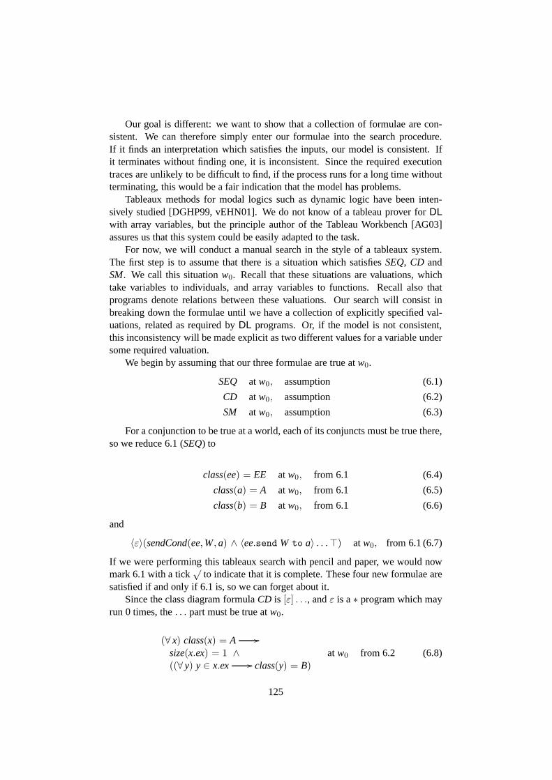
Our goal is different: we want to show that a collection of formulae are con-sistent. We can therefore simply enter our formulae into thesearch procedure.If it finds an interpretation which satisfies the inputs, our model is consistent. Ifit terminates without finding one, it is inconsistent. Sincethe required executiontraces are unlikely to be difficult to find, if the process runsfor a long time withoutterminating, this would be a fair indication that the model has problems.
Tableaux methods for modal logics such as dynamic logic havebeen inten-sively studied [DGHP99, vEHN01]. We do not know of a tableau prover for DLwith array variables, but the principle author of the Tableau Workbench [AG03]assures us that this system could be easily adapted to the task.
For now, we will conduct a manual search in the style of a tableaux system.The first step is to assume that there is a situation which satisfiesSEQ, CD andSM. We call this situationw0. Recall that these situations are valuations, whichtake variables to individuals, and array variables to functions. Recall also thatprograms denote relations between these valuations. Our search will consist inbreaking down the formulae until we have a collection of explicitly specified val-uations, related as required byDL programs. Or, if the model is not consistent,this inconsistency will be made explicit as two different values for a variable undersome required valuation.
We begin by assuming that our three formulae are true atw0.
SEQ at w0, assumption (6.1)
CD at w0, assumption (6.2)
SM at w0, assumption (6.3)
For a conjunction to be true at a world, each of its conjuncts must be true there,so we reduce 6.1 (SEQ) to
class(ee) = EE atw0, from 6.1 (6.4)
class(a) = A atw0, from 6.1 (6.5)
class(b) = B atw0, from 6.1 (6.6)
and
〈ε〉(sendCond(ee,W,a) ∧ 〈ee.send W to a〉 . . .⊤) atw0, from 6.1 (6.7)
If we were performing this tableaux search with pencil and paper, we would nowmark 6.1 with a tick
√to indicate that it is complete. These four new formulae are
satisfied if and only if 6.1 is, so we can forget about it.Since the class diagram formulaCD is [ε] . . ., andε is a∗ program which may
run 0 times, the. . . part must be true atw0.
(∀ x) class(x) = A //
size(x.ex) = 1 ∧((∀ y) y ∈ x.ex // class(y) = B)
at w0 from 6.2 (6.8)
125

The sequence diagram does not actually say thatb is a’s ex, but this was our inten-tion when creating the scenario, and it makes 6.8 true. We hope that the tableauxsystem would try this before introducing new instances ofB. Even so, it would takeseveral steps to do so, which we omit. Note that there are other ways of making 6.8true, so we do not mark it as completed at this stage. In particular we could assertthe existence of new instances ofB at w0. Although its fairly clear to humans thatthis would not help, a tableaux system could easily get stuckin an infinite sequenceof stupid ideas.
a.ex= {b} atw0, from 6.8 (6.9)
Now we turn to 6.7. Again, becauseε is a∗ program, we can satisfy the formulaat w0 by satisfying the subformula under the〈ε〉. If this failed, a tableaux systemwould begin checking other states that can be reached under the ε program. Wesplit the two conjuncts.
sendCond(ee,W,a) atw0, from 6.7 (6.10)
〈ee.send W to a〉 . . .⊤ atw0, from 6.7 (6.11)
Now 6.4 says thatee is an external entity, and the definition ofsendCond, says itcan send messages as it pleases, so 6.10 is true atw0.
To satisfy formula 6.11, we need a transition fromw0 to another situation re-sulting from the send action. We write
w0send W to a // w1 (6.12)
to say this. We also assume thata is in stateswith an emptyintray. This will meanthat a can accept the sentW message and make the intended transition. Again, aformal tableaux system might have to work to find that this is what is needed.
state(a) = s at wo, assumption (6.13)
intray(a) = () at wo, assumption (6.14)
As a result of thesend action,a will have aW message in itsintray.
intray(a) = (W) atw1, from 6.14, 6.12, df.send (6.15)
We now reinstate some of 6.11 which we had turned into. . .. To make it true atw0
we require its subformula to be true atw1.
〈ε〉(acceptCond(a) ∧ 〈a.accept〉 . . .⊤) atw1, from 6.11, 6.12 (6.16)
The conditionacceptCond(a) is true atw1 becausea has a message in its intraybut nothing in its todo list. To make the other conjunct true,we need anacceptstep to the next state.
w1a.accept // w2 (6.17)
126

Now the definition ofaccept , on Page 121, depends on the array variablesnextStateand entryProc, so its not immediately obvious what the situation will be inw2.However
(∀ x) state(x) = s ∧ head(intray(x)) = W// [x.accept] state(x) = s′
atw1, from SM (6.18)
and therefore
state(a) = s′ at w2, from 6.13, 6.15, 6.17, 6.18 (6.19)
It follows from this that, at least atw1, nextState(s,W) = s′, and since we are notconsidering any programs which updatenextState, we can consider this to be thevalue everywhere. Similarly, at least in effect (since we donot actually useself),entryProc(s′) = send X to self.exbecause
(∀ x)[x.accept](state(x) = s′ // todo(x) = send X to x.ex) atw1, from 6.3(6.20)
and sotodo(a) = send X to a.exatw2, from 6.17, 6.19, 6.20 (6.21)
Assume that values are equal to their singleton sets, so{b} = b.
todo(a) = send X to b atw2, from 6.9, 6.21 (6.22)
Thus we can satisfy 6.16 if we can satisfy
〈ε〉(sendCond(a,Y,b) ∧ 〈a.send Y to b〉⊤) atw2, from (6.16)(6.17) (6.23)
and now, it would appear that we are stuck, because it seems nothing that canpossibly happen is going to putsend Y to b into a’s todo list, which we need inorder to satisfysendCond(a,Y,b). But recall thatX andY are variables. Henceeach valuation maps them both to individuals in the semanticdomain. Ifw2 mapsXandY to thesameindividual, thensendCondis satisfied, thesend can proceed andthe sequence successfully completes, showing that it is consistent with the modeldefined by the class and state machine diagrams.
This is clearly not how the story is supposed to end. We are developing aformal theory of our intuitive understanding of the diagrams, and our intuition saysthey are inconsistent, becauseX is X, Y is Y, and they can not be the same thing.That is “X” is not just a label we stick on that message from outside the system,but rather something essential to its identity. We can capture this idea formally byretrospectively asserting the following naming invariant
NAMES≡ [ε](name(X) = “X” ∧ name(Y) = “Y” ∧ · · · ∧ name(s′) = “s′”)
which makesX = Y impossible. It also prevents the classesA andB from beingthe same, and also weird possibilities likeA = s, identifying a class and a state.
127

(Although Mellor [Mel03] has made suggestions that are almost this strange whendiscussing how domain models might be woven together.)
So now there really is no way to find a situation withsend Y to b ona’s todolist, so the sequence diagram is inconsistent with the model. This could be provenby induction on the definition ofε.
6.4 Interactions as Dynamic Formulae
This chapter has presented a formalisation of a UML fragmentincluding the sim-plest elements of class diagrams, state machines, actions and sequence diagrams.The formalisation has its weaknesses. It directly treats diagrams rather than UML’sabstract syntax. The semantics are derived from our readingof [MB02] rather thanthe official definition. Dynamic logic lacks types and specialisation, and we havenot attempted to encode them. TheDL variant used in [WS96, WB97] has orderedsorts for this purpose. We have no concurrency, though concurrent dynamic logicshave been studied [Pel87]. Readability must also count as a serious weakness ofdynamic logic formulae.
Despite all this, the basic principles underlying this worksuggest an alterna-tive to UML’s treatment of Interactions. In this chapter, a UML system state is avaluation of variables, including some “array variables” which are effectively up-dateable functions. One action and one form of causation were defined as dynamiclogic programs, that is, modal operators. We used these to define legal systemevolution, so that we could make assertions of the form, “after [any|some] legalevolution of the system, such and such is the case”. These definitions of actionand causation were also used as OccurrenceSpecifications inthe Interaction. Eventoccurrences here are not persistent entities added to the system state to record itshistory. Rather they are the transitions between system states. Instead of look-ing at the recorded history after the fact, the dynamic logicformula version of theInteraction looks at the possible evolutions of the system.
How could we integrate this version of Interaction semantics into the graphtransformation based UML semantics we have outlined in previous chapters?
A graph transformation system would be generated by rules, one for each con-crete UML action and kind of causation such as accepting an operation call. Eachof these rules would have a name, which would be used to label the transitionsin which the rule was applied. Some transitions would be labelled with severalrule names, since several things can happen concurrently. Each rule application isdetermined by amatch, a graph homomorphism that chooses nodes in the systemstate to play the roles defined by the rule. Key participants could also be includedin the transition label, so for example, a transition may be labelleda send y to b,wherey is a Signal instance anda andb are objects.
These transition labels could be the atomic programs of a UMLspecific dy-namic logic. So for example, the Interaction of our example model could representthe formula
128
(∃ ee,a,b, y)y : Y ∧ 〈eesend w to a; a accept w; a send y to b〉⊤
We quantify the run-time participants, but not the SignalY which is part of themodel. Sequential composition is not always appropriate, since the ordering ofevent occurrence specifications in an Interaction can be properly partial, as wesaw in Section 5.4. One solution would be to include a set composition to thelanguage. This would apply to a set of programs, and would be satisfied by apath that includes each of them in any order. “Includes” rather than “consists of”because as we pointed out in the body of this chapter, sequence diagrams should notbe expected to spell out everything that happens. Another option would be to definea partial order composition operator to directly capture Interaction semantics.
These two possibilities would be executed by writing an interpretation functionwhich would examine the relevant model elements and yield a formula of somegraphical dynamic logic. That logic could also be used as a constraint language. Itmay be possible to instead define the value of an Interaction in a given system statedirectly, as we did in Chapter 4 with Property. A similar approach could be appliedto Multiplicities, but semantics for OCL would remain a problem.
Event occurrences are not only “truth-makers” for Interactions. Recall that inSection 5.3, we found that objects maintain a “pool” of eventoccurrences, whichthey may respond to at some later time. This role is not so easyto reconcile withour proposal that event occurrences should be system state transition labels. Per-haps these persistent entities in the system state should instead be considered asnotificationsof event occurrences. Thus, when they are “consumed” they can dis-appear. It also makes better sense of occurrences such as TimeEvent instances.Although the time changes constantly, there are only certain circumstances whenit is required tonotify some object about it.
There are clearly many details to be worked out, but it seems that a dynamiclogic approach as we have outlined might be a way to make much better sense ofInteractions than the current definitions recorded historyapproach.
129
Chapter 7
The UML FormalisationLiterature
UML models are not clearly understood by their users. There are two reasons forthis. Firstly the semantic domain of the language is only partially and somewhatinconsistently defined. Secondly, the definition is very complicated and difficult toread. What is needed is a complete, precise and easy to understand definition thatagrees with the current one.
We have been carefully studying the language trying to clarify what modelsmean. In Chapter 3 we noticed that models and system states consist of things, or“objects”, with named values attached to them. We also noticed that the core of themetamodel is actually a mathematical definition for exactlythis kind of structure:an edge-labelled directed multi-graph. Apart from the previous chapter which useddynamic logic, we have held the working hypothesis that UML systems are graphtransformation systems.
This hypothesis has been able to explain everything we have encountered sofar, but a hypothesis which works is not necessarily the besthypothesis. In thisChapter, we survey the wide variety of work which has attempted to give precisemeaning to UML, or to parts of it. It is important to note that alot of this work doesnot explicitly set out to solve the UML definition problem as we have conceived it.Often the contributions seek to apply specific tools to specific verification problemsand as a byproduct, give a formalisation of part of the language.
The first section presents the well known relational model and entity relation-ship model from database theory, not as possible UML formalisation techniques,but as examples of conceptual clarity that UML should aspireto.
Each of the following sections are centred around a particular formalism. Eachbegins with a short introduction to that formalism, and outlines the ways in whichit has been used. We then examine in some detail two or three ofthe most signif-icant papers that apply that technique. A concise survey of the remainder of therelevant literature is then followed by an assessment of this technique according tothe criteria we developed in Chapter 2. These criteria are briefly recalled in Table
130
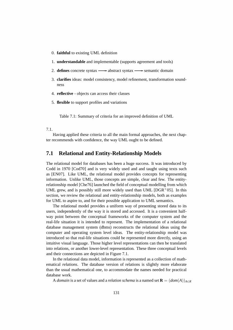
0. faithful to existing UML definition
1. understandableand implementable (supports agreement and tools)
2. definesconcrete syntax // abstract syntax // semantic domain
3. clarifies ideas: model consistency, model refinement, transformation sound-ness
4. reflective - objects can access their classes
5. flexible to support profiles and variations
Table 7.1: Summary of criteria for an improved definition of UML
7.1.Having applied these criteria to all the main formal approaches, the next chap-
ter recommends with confidence, the way UML ought to be defined.
7.1 Relational and Entity-Relationship Models
The relational model for databases has been a huge success. It was introduced byCodd in 1970 [Cod70] and is very widely used and and taught using texts suchas [EN07]. Like UML, the relational model provides conceptsfor representinginformation. Unlike UML, those concepts are simple, clear and few. The entity-relationship model [Che76] launched the field of conceptualmodelling from whichUML grew, and is possibly still more widely used than UML [DGR+05]. In thissection, we review the relational and entity-relationshipmodels, both as examplesfor UML to aspire to, and for their possible application to UML semantics.
The relational model provides a uniform way of presenting stored data to itsusers, independently of the way it is stored and accessed. Itis a convenient half-way point between the conceptual frameworks of the computersystem and thereal-life situation it is intended to represent. The implementation of a relationaldatabase management system (dbms) reconstructs the relational ideas using thecomputer and operating system level ideas. The entity-relationship model wasintroduced so that real-life situations could be represented more directly, using anintuitive visual language. Those higher level representations can then be translatedinto relations, or another lower-level representation. These three conceptual levelsand their connections are depicted in Figure 7.1.
In the relational data model, information is represented asa collection of math-ematicalrelations. The database version of relations is slightly more elaboratethan the usual mathematical one, to accommodate the names needed for practicaldatabase work.
A domainis a set of values and arelation schemais a named setR = (dom(A))A∈R
131

ER Model
Relational Model
Computer
translation
DBMS implemention
Figure 7.1: Three conceptual levels in databases
of domains indexed byattributenames. This is more often written as
R(A1 : dom(A1), . . . ,An : dom(An)),
and the attributes considered as ordered from 1 ton. Therelation states, or simplyrelationsof this relation schema are the subsets of
∏
A∈R dom(A) or
dom(A1)× . . .× dom(An).
These two sets are usually considered equal in database theory. A database schemais a collection of relation schemas, and astateof a given database schema is acollection of named relation states, one for each of the relation schemas.
The tuples in these relations often represent some real world entity, with eachattribute value in the tuple representing some property of that thing. The kindof things represented by a relation may be uniquely identified by some propertyor properties, such as a student number, or the combination of post code1, streetname and number. In this case we want to avoid having distincttuples with thoseattribute values in common, because this would be contradictory information aboutthe thing represented.
This difficulty is catered for by imposing aconstraint, a condition restrictingthe set of database states that are consideredvalid instances of the database schema.A keyconstraint specifies a subsetK of the attributes of a relation schemaR, andasserts that if for a pair of tuplesr, t in a stateR of R we haveπk(r) = πk(t) foreach attributek ∈ K, thent = r. That is, we can not have distinct tuples that agreeon the key. Another way of looking at this is that the relationbecomes a partialfunction from the key to the remainder of the attributes. It is usual to nominate asingleprimary key for each relation schema.
To extract the required information from a database, it is often necessary tojoin relations. To find a student’s timetable for example, the tuple representing thatstudent must be connected to tuples representing the courses she is enrolled in, and
1In the USA, this is called a “zip code”.
132
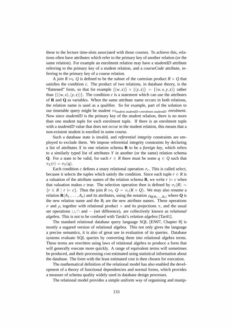
these to the lecture time-slots associated with those courses. To achieve this, rela-tions often have attributes which refer to the primary key ofanother relation (or thesame relation). For example an enrolment relation may have astudentIDattributereferring to the primary key of a student relation, and acourseCodeattribute, re-ferring to the primary key of a course relation.
A join R ⊲⊳c Q is defined to be the subset of the cartesian productR× Q thatsatisfies the conditionc. The product of two relations, in database theory, is the“flattened” form, so that for example{(w, x)} × {(y, z)} = {(w, x, y, z)} ratherthan{((w, x), (y, z))}. The conditionc is a statement which can use the attributesof R andQ as variables. When the same attribute name occurs in both relations,the relation name is used as a qualifier. So for example, part of the solution toour timetable query might bestudent⊲⊳student.studentID=enrolment.studentID enrolment.Now sincestudentIDis the primary key of thestudentrelation, there is no morethan one student tuple for each enrolment tuple. If there is an enrolment tuplewith astudentIDvalue that does not occur in the student relation, this meansthat anon-existent student is enrolled in some course.
Such a database state is invalid, andreferential integrityconstraints are em-ployed to exclude them. We impose referential integrity constraints by declaringa list of attributesX in one relation schemaR to be aforeign key, which refersto a similarly typed list of attributesY in another (or the same) relation schemaQ. For a state to be valid, for eachr ∈ R there must be someq ∈ Q such thatπX(r) = πY(q).
Each conditionc defines a unary relational operationσc. This is calledselect,because it selects the tuples which satisfy the condition. Since each tupler ∈ R isa valuation of the attribute names of the relation schemaR, we writer |= c whenthat valuation makesc true. The selection operation then is defined byσc(R) ={r ∈ R | r |= c}. Thus the joinR ⊲⊳c Q = σc(R× Q). We may alsorenamearelationR(A1, . . . ,An) and its attributes, using the notationρQ(B1,...,Bn) whereQ isthe new relation name and theBi are the new attribute names. These operationsσ andρ, together with relational product× and its projectionsπ, and the usualset operations∪,∩ and− (set difference), are collectively known asrelationalalgebra. This is not to be confused with Tarski’srelation algebra[Tar41].
The standard relational database query language SQL [EN07,Chapter 8] ismostly a sugared version of relational algebra. This not only gives the languagea precise semantics, it is also of great use in evaluation of its queries. Databasesystems evaluate SQL queries by converting them into relational algebra terms.These terms are rewritten using laws of relational algebra to produce a form thatwill generally execute more quickly. A range of equivalent terms will sometimesbe produced, and their processing cost estimated using statistical information aboutthe database. The form with the least estimated cost is then chosen for execution.
The mathematical definition of the relational model has alsoenabled the devel-opment of a theory of functional dependencies and normal forms, which providesa measure of schema quality widely used in database design processes.
The relational model provides a simple uniform way of organising and manip-
133

ulating data, insulating the user from the variety and complexity of storage andimplementation. However, there remains a considerable conceptual gap betweenmathematical relations and the way we see those parts of the world that we wantto represent in databases. Chen [Che76] distinguishes between four levels of view,the highest being “information concerning entities and relationships which exist inour minds.” The relational model, he says, is concerned withthe middle two levels“organisation of information in which entities and relationships are represented bydata” and “the data structures which are not involved in search schemes, indexingschemes, etc”. The lowest of the four levels is the “access-path-dependent datastructure”.
The entity-relationship model represents entities and relationships directly asdata value sets and relations. Note that Chen carefully describes his data model asa mathematical structure. The much more widely known visualnotation of entityrelationship modelling is given a precise meaning in terms of this mathematicaldata model. Never the less, it directly addresses the highest level “view” of in-formation, the entities that we recognise in the world and relationships that existbetween them. Chen also describes possible translations from his data model intothe relational model.
The relational and entity relationship models can be seen asancestors of UML,and UML ought to aspire to the conceptual clarity and widespread use that thesemodels enjoy. One of the earliest popular object oriented modelling methods, theShlaer-Mellor method [SM88, SM92] employed a modest extension of these mod-els, adding state machines to describe object lifecycles. UML has its own some-what defined conceptual model. To what extent can this model be reduced to therelational or entity-relationship models? That is, could UML system states be de-fined as database states?
One could begin by translating class diagrams as the corresponding conceptsof the entity-relationship model are translated, treatingclasses as entity sets, UMLattributes as entity-relationship attributes and associations as relationships. Thistranslation yields a relation for each class and a relation for each association with* at both ends. Where one end has a multiplicity with a finite upper bound, theassociation can be translated as attributes in the relationrepresenting the class at thefar end of that association. The “extended entity-relationship model” incorporates anotion of generalisation with a translation into the relational model [EN07, Chapter7]. This is the kind of translation that is employed when UML is used to designrelational databases.
UML’s object oriented model is not the same as the entity-relationship model.The identity of an object does not depend on its attribute values. To capture this inthe relational model, an object identifier attribute would need to be added to eachrelation representing a class. As we discussed in Chapter 4,the semantics of UMLassociations remains undecided. Depending on the outcome of that debate, it maybe necessary to include a separate identifier attribute to relations translated fromassociations too. The primary key of a relation obtained from a binary relationshipis usually the two foreign keys referring to the entity relations at its ends. This
134
id P1 [a,b,c]
⇒ id1
id pos P1 1 a1 2 b1 3 c
Figure 7.2: Normalising a list valued attribute
does not allow the possibility of a pair of entity/objects having more than one linkbetween them from the same relationship/association.
Whilst object and link identity can be handled by simply adding identifier at-tributes, there is a much deeper conceptual mismatch between the UML and re-lational notions of attribute. Codd [Cod70] gave a definition of first normal form(1NF) which says that attribute values are “simple”, that is, neither sets nor tuples.This condition is now considered, in database theory, to be part of the definitionof relation itself [EN07,§10.3.4]. On the other hand, UML’s attributes are Proper-ties [Obj07b,§7.3.44], whose values can be sets, ordered sets, bags or sequences,depending on the settings of the meta-attributesisOrderedand isUnique. Repre-senting these kinds of values in the relational model would require normalisation.
Consider the most general case, of a sequence valued attribute. An exampleshowing normalisation of such an attribute is shown in Figure 7.2. Underlining isused to indicate each relations primary key.
The normalisation is similar to the standard one for set valued attributes, butadds an attribute to record the position of each value in the list. The set normali-sation would makeid andP the primary key, thus preventing the same value fromoccurring twice for the same object. The same value can occurtwice in a list, butthe same position can not, thus we have includedpos in the primary key. This stilldoes not ensure that we have a list because there may be “holes” in our sequence.That is, we must enforce a rather awkward integrity constraint, that the values ofthe new attributeposare an initial segment of the positive integers,{1, 2, . . . ,n}for somen.
When designing a database, one would of course translate each attribute or as-sociation according to its special properties, minimisingthe number of relationsin the resulting schema and the number of join operations required when query-ing it. It is desirable however, that a formal semantics be simple and uniform, tosimplify our reasoning about it. Complexity in the statics would also lead to ad-ditional complexity in the dynamics. For example, if different kinds of Propertieshad different semantics, the formal definition of the WriteStructuralFeatureAction[Obj07b,§11.3.54] would involve multiple cases.
A relational semantics for a given UML model would thereforecontain a lotof relations like the one at the far right of Figure 7.2. It is not hard to see that thisrelation is equivalent to a linearly ordered set of threeP labelled edges leaving thenode 1, which is how we formalised Properties in Chapter 4.
135
We have outlined the relational and entity-relationship models employed in thedatabase field. These models are firmly based on simple mathematical ideas. Thisconceptual clarity facilitates understanding and hence agreement, as sought by ourCriterion 1. The mathematical foundation also enables useful theory and tool sup-port. For example, relational algebra enables query optimisation, and functionaldependencies and normal forms allow objective assessment of schema quality andautomated support for the design process. UML should aspireto this level of clar-ity, but we found that it is not practical to directly employ the relational model todo this. In particular, UML’s object identity and collections do not fit well in therelational model.
7.2 Graph Transformation
Since Chapter 3, it has been our hypothesis that the semanticdomain of UML isgraphs, and in Section 5.6 we began to consider graph transformation for UML’sdynamic semantics. A great many other workers have come to this conclusionbefore us, and in this section we introduce graph transformation more carefully,then study and assess the contributions that apply this theory to the formalisationof UML.
At school we learn rules that can be used to simplify algebraic terms, for ex-ample,x× (y + z) = (x× y) + (x× z). The same technique can be applied forcomputation in all kinds of abstract algebras using term rewriting systems [BN98].The algebraic terms can be used to model system states, with the rewrites repre-senting state transitions.
Now terms are trees, with eachn-ary function symbol occurrence as a nodewith n outgoing edges. Each of these nodes also has one incoming edge, exceptfor the outermost function symbol occurrence, which is the root of the tree. Atree is a directed graph, with a unique path from the root to each node. Graphtransformation extends this rule based updating of these special kinds of graph, tographs in general.
A term rewriting rule is just an equation, such asx × (y + z) = (x × y) +(x× z), but considered as directed from left to right. To apply the rule, we findan instance of the left hand side somewhere in a term, and replace it with theright hand side, instantiated in the same way. These ideas can be defined withmathematical precision [BN98], which we shall outline in the following example.The term15+(3×((2×w)+4)) may be rewritten to15+((3×(2×w))+(3×4))using our example rule, because the subterm3 × ((2 × w) + 4) is an instance ofx× (y + z). In particular, the substitutionσ = {x 7→ 3, y 7→ (2 × w), z 7→ 4}turns the left hand side of the rule into the subterm, and turns the right hand side ofthe rule into the replacement,(3 × (2 × w)) + (3× 4), of that subterm. In formaldefinitions such as those in [BN98], each node of the originaltree, and hence eachsubterm of the original term, is identified by itspositionin the tree.
This is rather simpler than the general graph case. The left hand side of the term
136

rewriting rule has a root node, and this must bematchedwith a single position inthe input tree. The subtree rooted at that position is removed, and replaced withthe substituted version of the right hand side of the rule. The two sides of a graphtransformation rule are both general graphs. There is no distinguished node whichguides how it can match the input. Each node of the left hand side must be mappedto some node in the input, and the edges mapped in agreement with the mappings oftheir source and target. Such a mapping of graphs is called a graph homomorphism,which we defined in Definition 3 (on Page 45). The parts that need to be removedfrom the input graph, are those which match parts of the left hand side of the rulethat do not occur on the right hand side. Similarly, the partsthat must be added tothe input graph are those nodes and edges from the right hand side of the rule thatdo not occur on the left.
There are several alternative ways of defining these ideas formally, but we focuson the one that seems most popular in the UML related literature, and which istreated thoroughly in the recent monograph [EEPT06]: the double pushout method.The outline which follows is mostly drawn from this book. Pushout is an idea fromcategory theory which is used in this method to define what it means to “glue” twographs together. This is obviously helpful for adding the nodes and edges fromthe right hand side of the rule, but it is also used to remove parts of the graph by“ungluing” them.
Let’s say we have two graphsB andC which we wish to “glue together” form-ing a new graphD. We must also specify which nodes and edges inB are to beglued to which nodes and edges inC. The resulting graphD will “contain” copiesof bothB andC, but someD nodes and edges will be in both copies. These nodesand edges at the intersection of the input graphs are a subgraph of the resultinggraph, showing where the gluing has occurred.
A pushout is a special “bottom corner” for a given “top corner” of functions.This is shown at the left of Figure 7.3, with the given top corner shown as solidarrows, and the pushout bottom corner shown with dashed lines. In fact, the arrowsin category theory need not be functions, and the objects at the ends of the arrowsneed not be sets or set based structures like graphs. We will ignore this level ofgenerality, and just consider the case where the objects aregraphs and the arrowsare graph homomorphisms. There are a couple of conditions for f ′,g′,D to be apushout. First, the square must commute, which means that the top-left path mustgive the same results as the right-bottom path, that isg′ ◦ f = f ′ ◦ g. Secondly,the pushout must be universal, or limiting, in the sense that, for any other cornerthat makes the square commute, there must be a unique arrow from the pushoutto this other corner. This idea is pictured in the right hand side diagram in Figure7.3. The arrowsh andk and the graphX are an alternative bottom corner forming acommuting square. By saying that our pushoutf ′,g′,D is universal, we mean thatfor any alternative corner, such as the one shown, there is a unique arrow, in thiscasex, which converts the pushout into that corner. That is to say,x ◦ f ′ = k andx ◦ g′ = h.
Now, here is what we do if we want to glue two graphs together. We call one
137

C Df ′
//_____
A
C
g
��
A Bf // B
D
g′
�������
C Df ′
//
A
C
g
��
A Bf // B
D
g′
��
B
X
h
��///
////
////
////
////
///
D
X
x
��??
??
??C
X
k
''OOOOOOOOOOOOOOOOOOOOOO
Figure 7.3: Commuting square (left) and a pushout (right)
of the graphsB and the otherC. We make another graphA which shows the gluedintersection of the resulting graph. For each node inA, we show which node inBand which node inC will be at that place, by setting the value of the functionsf andg respectively, and similarly for the edges. We then construct a pushout over thiscorner, and the resulting graphD will be the glued together result that we require.
This is proven, though disguised in rather technical language, in [EEPT06,Fact 2.17]. In particular, it shows four things, each of which is part of what weintuitively expect of a glued together graph. We will take a brief look at eachof these four points, explaining why the stated property is desirable. Each of thequotes are from the Fact just cited.
“If f is injective (or surjective), thenf ′ is also injective (or surjective).” We areusingf andg to show which pairs of nodes and edges to glue together, with eachpair having one element fromB and one element fromC. If f was not injective,then two elements ofA are mapped to the same element ofB, and thus both wouldbe glued to some element ofC and hence to each other. This amounts to gluingthe graph to itself rather than just to another graph, sof andf ′ are indeed injective.Thatf ′ is injective means thatD contains a complete copy ofC. Similarly, becauseg and henceg′ are injective,D contains a complete copy ofB.
“The pair (f ′,g′) is jointly surjective, i.e. for eachx ∈ D there is a preimageb ∈ B with g′(b) = x or c ∈ C with f ′(c) = x.” This means that there is no “junk”in the resulting graphD. Everything there is copied fromB or C or both.
“If f is injective andx ∈ D has preimagesb ∈ B andc ∈ C with g′(b) =f ′(c) = x, then there is a unique preimagea ∈ A with f (a) = b and g(a) =c.” Recall that we ask for a pair of things to be glued together by mapping someelement ofA to the two elements of the pair. So this is telling us that the only pairsof things which have been glued together are the pairs of things we said to gluetogether.
“If f and hence alsof ′ is injective, thenD is isomorphic toD′ = C⊎B\ f (A).”That is, the resulting graph is just like the disjoint union of the two input graphs,except there is only one copy ofA, which is because the two copies have been
138
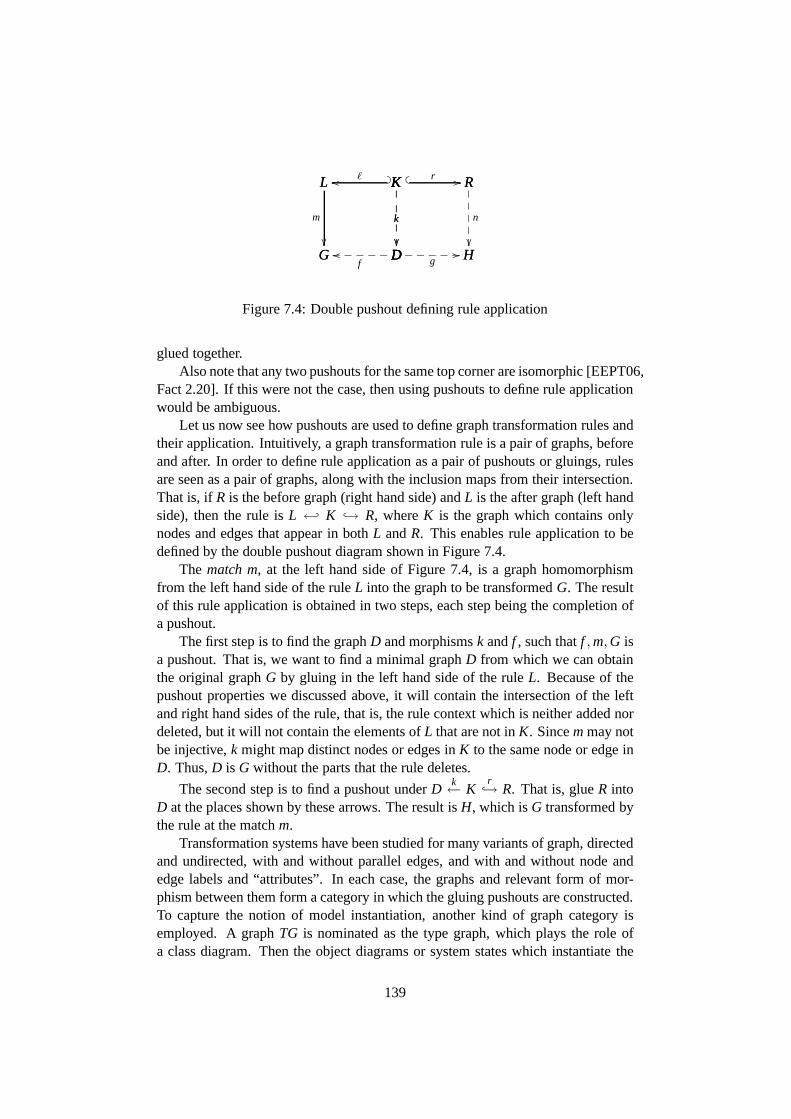
G Doof
_____
L
G
m
��
L Koo ℓ? _K
D
k
��
����
D Hg//_____
K
D
k
��
����
K R� � r // R
H
n
�������
Figure 7.4: Double pushout defining rule application
glued together.Also note that any two pushouts for the same top corner are isomorphic [EEPT06,
Fact 2.20]. If this were not the case, then using pushouts to define rule applicationwould be ambiguous.
Let us now see how pushouts are used to define graph transformation rules andtheir application. Intuitively, a graph transformation rule is a pair of graphs, beforeand after. In order to define rule application as a pair of pushouts or gluings, rulesare seen as a pair of graphs, along with the inclusion maps from their intersection.That is, ifR is the before graph (right hand side) andL is the after graph (left handside), then the rule isL ← K → R, whereK is the graph which contains onlynodes and edges that appear in bothL andR. This enables rule application to bedefined by the double pushout diagram shown in Figure 7.4.
The match m, at the left hand side of Figure 7.4, is a graph homomorphismfrom the left hand side of the ruleL into the graph to be transformedG. The resultof this rule application is obtained in two steps, each step being the completion ofa pushout.
The first step is to find the graphD and morphismsk andf , such thatf ,m,G isa pushout. That is, we want to find a minimal graphD from which we can obtainthe original graphG by gluing in the left hand side of the ruleL. Because of thepushout properties we discussed above, it will contain the intersection of the leftand right hand sides of the rule, that is, the rule context which is neither added nordeleted, but it will not contain the elements ofL that are not inK. Sincemmay notbe injective,k might map distinct nodes or edges inK to the same node or edge inD. Thus,D is G without the parts that the rule deletes.
The second step is to find a pushout underDk← K
r→ R. That is, glueR intoD at the places shown by these arrows. The result isH, which isG transformed bythe rule at the matchm.
Transformation systems have been studied for many variantsof graph, directedand undirected, with and without parallel edges, and with and without node andedge labels and “attributes”. In each case, the graphs and relevant form of mor-phism between them form a category in which the gluing pushouts are constructed.To capture the notion of model instantiation, another kind of graph category isemployed. A graphTG is nominated as the type graph, which plays the role ofa class diagram. Then the object diagrams or system states which instantiate the
139

F Gh //F
TG
f
��???
????
????
? G
TG
g
������
����
����
Figure 7.5: Arrows in the category of graphs typed overTG
class model are represented by pairs consisting of a graphG and a homomorphismg : G // TG. These are the objects of the category of graphstyped over TG. Anarrow(F, f ) // (G,g) in this category is a graph homomorphismh : F // Gwhich makes the triangle of Figure 7.5 commute, ief = g ◦ h. (This is an exam-ple of aslicecategory, which is in turn a simple form ofcommacategory [BW90,Pages 3 and 13].) This just means that ifh maps one object to another, they musthave the same class.
The obvious starting point in the graph transformation literature is Baresi andHeckel’s “Tutorial Introduction to Graph Transformation:A Software EngineeringPerspective” [BH02]. The ideas of graph transformation areintroduced using onlya little basic mathematics, and the many variations of graphand graph transfor-mation are outlined. This is followed by a survey of the literature on applicationsto software engineering, mostly related to the syntax and semantics of visual lan-guages. Type graphs are explained as a formalised version ofmetamodels. Thisis an advance over other formalisation techniques, which abandon metamodelling,replacing it with traditional grammar. Two ways are distinguished of using graphtransformation to define semantics. The first is to write rules, once and for all,defining a “language interpreter”. The paper of Engels, Hausmann, Heckel andSauer [EHHS00] is cited as an example of this. The second way is to define atranslation, which takes a model, and yields rules defining atransition system forthat model. The work of the Martin Gogolla’s “Bremen school”2 follows this plan[ZHG05, KG01]. We discuss both approaches below.
Functional and architectural models are distinguished, and graph theoretic tech-niques are shown for integrating them. Concrete syntax, abstract syntax and thesemantic domain can all be defined using graphs, and important relationships be-tween these can be defined using graph transformations. For example, parsing ofconcrete diagrams into abstract syntax, layout of abstractsyntax to yield concretediagrams, editing of abstract syntax using a graph grammar,and visualisation ofmodel execution. There are sections on the available software tools, and on theo-retical work such as concurrency and term graph rewriting for efficient evaluationof functional languages. Many of the main ideas are demonstrated by examples,and the bibliography is very extensive. This tutorial is an excellent introduction tograph transformation for visual language semantics.
2so called by Hausmann [Hau05] of Paderborn
140
The recent monograph [EEPT06] consolidates and presents research on thedouble pushout approach to graph transformation systems. It mentions UML, andgives many examples using graph transformation systems to model computer sys-tems, but does not directly address the problem of defining UML’s semantics. Thefirst of its 4 parts outlines graph transformation systems ina relatively straight for-ward algebraic way, using category theory only as needed to define rule applicationby pushouts. The second introduces adhesive high-level replacement categories,which admit the common kinds of graph transformation systems as special cases.The third treats the author’s notion of “attributed graph” (there are competing no-tions). They claim this rather complicated graph variant issuitable “to specify andimplement visual modeling techniques such as UML” (Page 171), but give no jus-tification. This kind of graph transformation system is implemented in their toolAGG, which is the topic of the fourth part. A case study is presented of a modeltransformation between UML statecharts and petri nets.
The other standard reference on graph transformation is the3 volume handbook[REE+99]. This is broader in scope, covering all approaches to defining graphtransformation steps, but a little less up to date. Manfred Nagl has been a prominentcontributor to the graph transformation literature from the mid 1970’s [Nag76] tothe present day. Another prominent worker in this field is Andy Schurr. Someof Schurr’s work addresses aspects of UML, or is applicableto it [ES95], but wehave not seen anything from Schurr or Nagl that suggests an approach to definingcomplete semantics for the language.
That completes our introduction to graph transformation and the more generalliterature on it. There are two distinct well developed approaches to applying graphtransformation theory to the formalisation of UML, each supported by several pub-lications. The next subsection studies the most promising of these approaches. Theother major body of work is covered in the following subsection, along with a fewother graph related contributions.
Dynamic Metamodelling
Dynamic metamodelling is an approach to the definition of UMLdeveloped at theUniversity of Paderborn primarily by Jan Hausmann, Gregor Engels and ReikoHeckel [EHHS00, EHHS02, Hau05, ESW07]. It draws on theoretical work of An-drea Corradini and Ugo Montanari of the University of Pisa incollaboration withHeckel [CHM00]. The UML metamodel is written in a subset of UML whichmainly consists of the simpler parts of class diagrams. Dynamic metamodellingextends the metamodelling language to include operations and collaboration dia-grams. The operations are used to represent the things that can happen in a UMLdefined system, such as an object sending a message, triggering a state machinetransition and so on. The operations are defined by graph transformation rules,and system state transitions are labelled with these operations when they are gener-ated by the corresponding rule. The rules are formulated using UML collaborationdiagrams. The parts of the system state that are to be removedare marked in the
141
diagram with{destroy } and the parts to be added marked{new}. Also added tothe metamodel are classes describing the auxiliary elements of the run-time seman-tic domain, such as activity executions and tokens. The metamodel then acts as atype graph for a graph transformation system. Thus a formal semantics for the lan-guage can be specified by a metamodel using this slightly expanded sublanguageof UML.
This approach was first presented in [EHHS00]. The semanticsare appliedto the model consistency problem in a surprising way in [EHHS02]. Rather thantake a model and answer the question, “is it consistent?”, this approach takes twoseparate models along with a specification of “consistency constraints” and testswhether the two models are consistent with one another, in the sense specified.We accept that different phases of development have different consistency require-ments, determined by whether the model is a partial or complete description, butdividing a model into two so that an inconsistency can be found seems almost ashard as simply finding the inconsistency. Hausmann’s PhD thesis [Hau05] worksthrough the DMM proposal in detail, applying it to a fragmentof UML activitydiagrams which he then analyses using the graph transformation system modelchecker Groove [Ren03]. (Model checking is discussed in Section 7.3 on page148.) A similar study of activity diagram formalisation using DMM is presented in[ESW07]. Here the aim is to automatically test the activities against criteria takenfrom the literature on workflows. These criteria are coded into computational treelogic (CTL) so that Groove can check whether they are satisfied by the transitionsystem specified by the example activity diagram.
Hausmann’s thesis [Hau05] is very similar to the present work in its aims andits conclusion. We therefore take a moment to outline that work and compare itwith our own. The first chapter introduces software modelling and the problemof informally defined semantics. In the next chapter, he distinguishes betweenconcrete syntax, abstract syntax, and semantics, and briefly examines the specialfeatures of UML and similar languages. Similarly to our Chapter 2 (publishedas [O’K06b]), Hausmann develops criteria for a definition technique, then appliesthese criteria in a survey of UML formalisations. We both require that a formalisa-tion be precise and understandable, support analysis by tools, define the completelanguage and be flexible or “universal”. The survey is admirable for its breadth,but writes off some major contributions such as [RCA01] witha one line tablerow, because they don’t explicitly offer a formalisation ofthe whole language. Weprefer to ask “could this technique define the whole language?” The remainingcontributions, he classifies into compilational, operational and hybrid semantics.
In fact, he refers to “denotational or compilational” semantics and includes[CEK01] under this heading, even though those authors say that “the semanticsdescribed in this paper is imperative and operational”. In adenotational semantics“the meaning of a well-formed program is a mathematical function from input datato output data” [Sch96]. Such a semantics for UML would simply not be a goodidea. Denotational semantics deliberately ignore programbehavior, but for UML,behavior is at least as important as functional computation. What the contributions
142
under this heading have in common is that they translate UML into another lan-guage which has well defined semantics, which is why he calls it “compilational”.Like many authors, Hausmann mistakenly calls this target language the “semanticdomain”. If the semantics of languageL is defined by translation into first orderlogic, then the semantic domain ofL is not first order logic but the semantic domainof first order logic, namely the class of Tarski-structures.
Included under the “denotational” heading is “denotational metamodelling”,which are approaches that give a model of the semantic domain, and a mapping ofthe syntax into it [KGR99]. We noted in Section 5.3 that the UML definition nowcontains fragments of a model of its semantic domain [Obj07c, §13.1], although itis only there to explain rather than to define. Many authors refer to such a modelas a “metamodel”. This is fair enough, in that it is a model of the things thatwe will use to model the world. The UML “metamodel” is really aprescriptivemodel of thelanguagewe use to describe those models. The “meta” is perhapsjustified by our argument in Chapter 1 that instances of the UML abstract syntaxactually are models as well as descriptions. In any case, we should take care todistinguish between models of the language and models of thesemantic domain.The DMM authors [Hau05, ESW07] take dynamic metamodelling to be a hybridof this “denotational metamodelling” approach, which covers the static semantics,and the operational technique of graph transformation to handle the dynamics.
The semantic mapping aspect of existing denotational metamodelling workseems inadequate to Hausmann, so he has developed the notionof “metarelation”to handle it. This is the topic of his third chapter. Neither the problem nor the solu-tion seem very clear to us. The following chapter introducesgraph transformationsystems, and then Chapter 5 describes the technique of dynamic metamodellingin detail. The remaining chapters and appendices give a casestudy and practicalguidelines for the application and automation of DMM.
The aim of the thesis is a method for defining UML-like languages, and thecontribution is a detailed proposal, which in our opinion isthe best currently avail-able. In contrast to our own work, Hausmann moves quickly over the nature of theproblem to be solved and the details of UML itself, and gets onwith exposing thenew ideas. Our contribution is more analytical and critical. We have studied thenature of modelling, carefully examined the existing UML definition and have nowembarked on a thorough survey of the formalisation literature. Our conclusions inChapter 8 will not be so detailed as Hausmann’s but they will be better supported,and thus a better foundation for further work.
All of the dynamic metamodelling work is based on the theoretical foundationof graphical operational semantics (GOS), which is presented in the brief workshoppaper of Corradini, Heckel and Montanari [CHM00]. It extends traditional graphtransformation systems by introducing rules which have premises and a conclusion,in the style of Plotkin’s structural operational semantics(SOS) [Plo81, AFV01].
As we saw earlier in this section, a term rewriting rule is just a directed equa-tion, a before termL and an after termR, perhaps with some shared variables. Wecould write such a rule asL // R. Term rewriting systems allow rules to ap-
143
ply to subterms, which in their usual algebraic applications makes sense, becauseif L = R then f (L) = f (R). SOS rules must match the whole term, which makessense for sequential programming languages, because you want the first instructionto be evaluated first. This restricted application to subterms is controlled by ruleswith premises. So in our sequential programming language example, we mighthave a rule
x // x′
x; y // x′; y
which only allows evaluation of the first subterm. Similarly, SOS allows specifica-tion of the evaluation order of terms such as(w + x) + (y + z). A term rewritingsystem would have distinct paths from this expression to itsvalue, one evaluatingleft subterm first, the other the right. Another advantage ofSOS specification isthat it allows the definition of transition systems with larger steps: “Part of thespirit of our method is to choose steps of the appropriate “size”” [Plo81]. Follow-ing the evaluation of a complex expression in a transition system generated by termrewriting would be very tedious. A transition system that takes expressions imme-diately to their value might be preferable for some purposes, or we might want tosee only the “major” steps. This can be arranged by making thekinds of transitionsyou want to see the conclusions of the rules, whilst the ones you don’t want to seebecome premises.
It is difficult to see how any of these advantages of structural operational se-mantics over plain term rewriting are applicable in the graph transformation case,especially when the goal is to formalise a behavioural language such as UML.
Each term has a root, or main-connective which classifies it,allowing the rightrules to target the right terms. Graphs do not have a hierarchical structure likethis. GOS rules, like ordinary graph transformation rules,are applied via a graphhomomorphism called amatch. To have the structural control of the transformationas SOS rules do, we would have to require this match be surjective, which would bean impractical limit on the state space: we want system states that are bigger thanthe left-hand-sides of graph transformation rules. In short, the structural benefitsof structural operational semantics can not be extended to graphs, because graphsdo not have that kind of structure.
What is the proper “size” for the transition steps in UML’s execution seman-tics? We suggest that since “all behavior in a modeled systemis ultimately causedby actions executed by so-called “active” objects” [Obj07c, §6.3.1], that each tran-sition represent the parallel execution of one or more actions. Since actions arethe atomic units of behavior, they should be represented by graph transformationrules, one rule for each of the 36 concrete actions. Thus no deduction system fortransitions is needed except for parallel composition [EEPT06,§3.3-4].
The approach to the formalisation of UML exhibited in the DMMwork orig-inates before the UML actions, and the substantial revisions of UML 2.0. Forexample, in [CHM00], an event occurrence is represented by atransition betweentwo system states. Such a transition is the premise for the rule which makes astate-machine transition. Thus the occurrence and its effect happen at the same
144
time. This is made possible by of the use of GOS, but is it desirable? As wenoted in Section 5.3, event occurrences and operation callsare not transitions, butpersistent entities that reside in “pools” and are later “consumed”.
DMM defines the semantic domain by extending the metamodel. Thus in-stances of this graph contain both the model proper and the system state, as werequired in Criterion 4. Small examples are given in [EHHS00] and [ESW07]. Inthe earlier paper, a fragment of the UML 1.3 metamodel describing objects andstatemachines is extended with an associationcurrentbetween metaclasses Objectand State, so that at run-time, instances of object can be linked to their currentstate. The later paper [ESW07] follows the same pattern by extending a fragmentof the activity part of the metamodel with runtime elements Offer, Token and Ac-tivityExecution.
The metaclass Object was included in the earlier UML metamodels. This waslater recognised to be a conceptual error, and it has been removed in UML 2.x. Itwas an error because objects are part of the world being described, but classes arepart of the description of that world. That is, classes are inthe syntax whereas ob-jects are in the semantic domain. For this reason, Object hasbeen replaced in UML2 by InstanceSpecification. Object and BehaviorExecution do appear in the “infor-mal” semantic domain model of [Obj07c,§13.1]. This model does not addressActivities, but if it were to be extended, the Offer, Token and ActivityExecutionclasses would fit comfortably.
Dynamic metamodelling deliberately merges the models of the language andthe semantic domain. Defining the semantic domain by extending the metamodelhas the happy effect of putting the model in each system state, although the hierar-chy does not continue. Unhappily the distinction between model and system stateis lost, because they are all described by elements of the same metamodel. Howdo we know that models may contain Classes and Activities, but not Objects andActivityExecutions? We guess that the current metamodel, asubset of the extendedone, would be designated as the syntax model. When the concerns of syntax andsemantics are separate, we have the possibility of using different languages to talkabout the same kinds of systems, or using the familiar language to talk about a newkind of system. This would be difficult under DMM. In Section 8.1 we outline away that syntax and semantics can be defined separately, thenmerged to create asingle type-graph in the style of dynamic metamodelling.
Dynamic metamodelling has found the right general approachto defining UML’ssemantics, but has erred in some of the details. In particular, UML’s action and cau-sation mechanism is not captured, probably because it was formulated after DMM.It is therefore not completely faithful to the existing language, as required by Cri-terion 0, but our own work in Chapter 5 indicates that a faithful version is possible.The approach is understandable (Criterion 1), it is based onuniform use of simplemathematics, but uses existing UML notation to express it. Because a system stateis an instance of the combined syntax/semantic domain metamodel, the user-modelis available in the run-time state, satisfying a single-level version of our Criterion4.
145
Other Graph Transformation Approaches
A different approach to defining UML’s semantics using graphtransformation sys-tems originates at the University of Bremen [ZHG05, GZK02].Its most maturepresentation so far is to be found in the 2005 paper of Paul Ziemann, KarstenHolscher and Martin Gogolla [ZHG05]. This paper describesintegrated formalsemantics for an impressive range of UML’s diagram types. They also describe apartially completed interactive model execution tool based on these semantics.
The dynamic metamodelling approach embraces the UML metamodel, extend-ing it to yield a type graph for the graph transformation system. The Bremen groupon the other hand, note that the definition of UML’s abstract syntax by a metamodelappears circular, and subsequently ignore it [ZHG05]. The type graph for theirgraph transformation systems contains a form of the class diagram fragment of themetamodel, including classes such as Class, Association and Operation, along withtheir run-time counterparts Object, Link and Process. Thus, the class diagram partof the metamodel is present in the system state. However the other diagram typesare handled in a variety of ad-hoc ways.
The meanings attributed to the diagrams is not derived from the official defi-nitions of the model elements they represent, but rather “relies on a number of as-sumptions on how the diagrams could be used in practise and integrated in a usefulway” [ZHG05]. So for example, they have chosen to use collaboration diagrams tospecify the sequence of operation calls used to implement another operation. Use-cases are also considered to be operation declarations. Thus what is presented isnot really a candidate forthe formal semantics of UML, but rather formal seman-tics for one particular style of UML use. This does not prevent us from consideringtheir general approach as a way of clarifying the existing semantics.
The most significant difference between this approach and dynamic metamod-elling is that here, each model yields a different graph transformation system.Many of the graph transformation rules are derived from the model’s diagrams.Hausmann says that this would make UML’s dynamics more complicated to under-stand and implement [Hau05, Page 31]. More importantly, in the official definitionthe UML Actions and run-time control and causation apparatus are described in ageneral way, once and for all. A formal definition should preserve this, if feasible.We believe that the dynamic metamodelling work discussed above, and our ownoutline of a graph transformation system show that it is feasible.
Gogolla, Favre and Buttner also have a paper proposing graphs with specialtyping edges, allowing them to “squeeze M0, M1, M2 and M3 intoa single ob-ject diagram” [GFB05]. Their aim is to give precise meaning to some metamodelproperties that are discussed in the literature, such as potency and strictness. Thesespecial edges can join pairs of nodes as usual, but can also join pairs of edges. In-terestingly, one of the properties they formulate, “strongly well-typed”, means thatthese edges are a graph homomorphism.
Another translation of a UML fragment into graph transformation systemsis presented in [BCG04]. In this paper Baldan, Corradini andGadduci use the
146

class diagram as a type graph, in this case a hypergraph. Eachnode has at mostone outgoing edge with several labelled “tentacles”. Thereis no discussion ofwhat difference this choice makes, or why it was made. Atomicactivities are de-fined as graph transformation rules using collaboration diagrams, as pioneered in[EHHS00]. They then study an activity diagram which specifies the sequencingof several such atomic activities. Given an initial state for their example system,they prove that the atomic activities can only be executed inthe order the diagramshows. That is, rather than treating the activity diagram asprescriptive, they con-sider it descriptive and requiring verification.
The much more significant contribution of this paper is the use of a logic, evalu-ated over the graph transformation system, to express and verify system properties.The logic used comes from the author’s earlier work on verification of graph trans-formation systems (but see [BCKL07], for more mature work).The static part ofthe logic is monadic second order, which means that it has variables for edges andfor sets of edges. Formulae of this logic are the propositional atoms of a modalµ-calculus, which allows the definition of the usual modal andtemporal operators.They use this logic to express several useful desired properties of their examplemodel, but find that it can not express others. Because the temporal operators cannot appear within the scope of a quantifier, it is not possibleto say anything aboutthe same object at two different points in time. They give an example “All boardedpassengers arrive at [their] destination.” The language isextended to allow thiskind of statement, but the authors did not know whether the verification techniquescould be extended to apply to this richer language. Further work on this questionappears in [BCKL07].
We were surprised by the treatment in [BCG04] of an activity diagram as adescriptive rather than a prescriptive diagram. A similar surprise is to be found inAliki Tsiolakis and Harmut Ehrig’s work [TE00]. Their aim isto check consistencybetween class and sequence diagrams. To do so, they translate the class diagraminto a type graph, and translate sequence diagrams into a controlled graph grammar.That is, a collection of graph transformation rules along with a control conditiondescribing their order of application. The association endmultiplicities of the classdiagram are also captured usinggraphical constraints, an idea due to Heckel andWagner [HW95]. Techniques are developed to check whether the sequence can beexecuted in a given state, and whether the resulting system states will be consistentwith the class diagram. This is achieved by checks involvingthe rules, and insome cases an initial state, without actually generating a sequence of system states.Unfortunately, the properties that are checked are not useful with respect to UMLas currently defined. For example, they insist that if an object sends a message toanother, then there must be a link between those two objects.Another example isthat their multiplicity constraint check does not account for any of the difficultieswe discussed in Chapter 4. However, techniques analogous tothose presentedwould be of practical benefit, if they were designed to test relevant properties ofsystems specified with UML as it is defined.
Model transformation is one of the key ideas of model driven development. If
147
models are graphs, then it is not surprising that the well studied theory of graphtransformation has also been applied to model transformation [VP02, GGL05,EEE+07].
Graph transformation is a very suitable way of defining UML, as we have beenarguing throughout this work. The formalisations of UML using graph transfor-mations that have been offered thus far are not sufficiently faithful nor extensive tobe convincing demonstrations, but dynamic metamodelling could become the basisof a definition that satisfies all our criteria. We prefer a single graph transforma-tion system “interpreter” approach, since this is more sympathetic to the existinginformal definition than a translation approach. The other main question is whatshould serve as the type graph, the user model or a semantic domain model? Theanswer, we believe is both. We show how this can be achieved inSection 8.1. Sev-eral contributions as well as our own work have shown that GTScan be used todefine both the abstract syntax and semantic domain of UML. Wehave seen thatmodel-checking and other techniques can be applied to test properties of systemsdefined in this way. Existing UML diagrams have been used in a natural way todefine graph transformations systems [EHHS00]. Therefore,if this subset of UMLis easy to understand, at least intuitively, then so are graph transformation systems.Reflection can be supported by instantiation edges. Flexibility has not been explic-itly addressed by any work we have seen, but one could clearlyvary the semanticdomain model or graph transformation rules as required. Thequestion would thenbe, how much of the underlying theory and tool support could be retained?
What remains to be done is to work out the details of a definition that it faith-fully captures and clarifies the language.
7.3 Logics
We see three distinct roles that a logic could play in definingUML. First, as a se-mantic foundation or replacement for OCL. Second, to replace the current flawedtreatment of Interactions or sequence diagrams (see Section 5.4). Thirdly, to fa-cilitate tool support, in particular, deductive verification and model checking. Thecontributions we study in this section do not always have goals that align with thisview, but this is what we are looking for. We begin by examining several contri-butions that verify UML models using logical model checking. This leads us intoyet another (see Sections 1.3 and 5.3) discussion of description verses prescriptionand its consequences for verification tasks. We also consider the expressiveness ofthe logics used. An example of deductive verification follows, and then we look atseveral papers on foundations for OCL and dynamic logic for modelling languagesemantics. For a brief introduction to formal logics including dynamic logic, seeSection 6.1.
Some of the work discussed in Section 7.2 on graph transformation employedmodel checking [Ren03, Hau05, ESW07]. Model Checking [MOSS99] takes alogical formula and a structure, and determines whether or not the structure satisfies
148
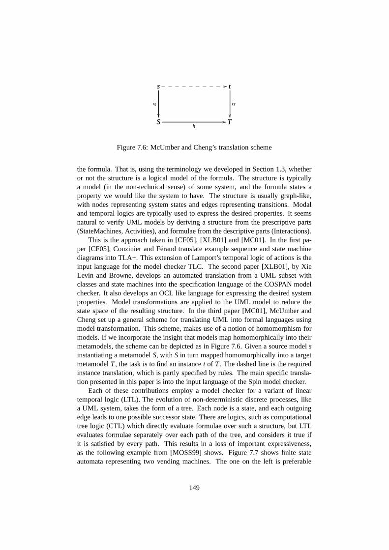
S Th
//
s
S
iS
��
s t//__________ t
T
iT
��
Figure 7.6: McUmber and Cheng’s translation scheme
the formula. That is, using the terminology we developed in Section 1.3, whetheror not the structure is a logical model of the formula. The structure is typicallya model (in the non-technical sense) of some system, and the formula states aproperty we would like the system to have. The structure is usually graph-like,with nodes representing system states and edges representing transitions. Modaland temporal logics are typically used to express the desired properties. It seemsnatural to verify UML models by deriving a structure from theprescriptive parts(StateMachines, Activities), and formulae from the descriptive parts (Interactions).
This is the approach taken in [CF05], [XLB01] and [MC01]. In the first pa-per [CF05], Couzinier and Feraud translate example sequence and state machinediagrams into TLA+. This extension of Lamport’s temporal logic of actions is theinput language for the model checker TLC. The second paper [XLB01], by XieLevin and Browne, develops an automated translation from a UML subset withclasses and state machines into the specification language of the COSPAN modelchecker. It also develops an OCL like language for expressing the desired systemproperties. Model transformations are applied to the UML model to reduce thestate space of the resulting structure. In the third paper [MC01], McUmber andCheng set up a general scheme for translating UML into formallanguages usingmodel transformation. This scheme, makes use of a notion of homomorphism formodels. If we incorporate the insight that models map homomorphically into theirmetamodels, the scheme can be depicted as in Figure 7.6. Given a source modelsinstantiating a metamodelS, with S in turn mapped homomorphically into a targetmetamodelT, the task is to find an instancet of T. The dashed line is the requiredinstance translation, which is partly specified by rules. The main specific transla-tion presented in this paper is into the input language of theSpin model checker.
Each of these contributions employ a model checker for a variant of lineartemporal logic (LTL). The evolution of non-deterministic discrete processes, likea UML system, takes the form of a tree. Each node is a state, andeach outgoingedge leads to one possible successor state. There are logics, such as computationaltree logic (CTL) which directly evaluate formulae over sucha structure, but LTLevaluates formulae separately over each path of the tree, and considers it true ifit is satisfied by every path. This results in a loss of important expressiveness,as the following example from [MOSS99] shows. Figure 7.7 shows finite stateautomata representing two vending machines. The one on the left is preferable
149

•��•
•
coin
��•
•
coffee
����������•
•
tea
��///
////
/
•��•
•
coin
����������•
•
coin
��///
////
/
•
•
coffee
��
•
•
tea
��
Figure 7.7: Example of expressive weakness: the two vendingmachines can notbe distinguished by LTL (taken from [MOSS99])
because after inserting a coin, the user can choose whether she wants coffee ortea, whereas in the right one, the machine makes the choice assoon as the coin isentered. However, the paths (or words) of these automata arethe same, and so theyare indistinguishable to LTL.
Is this expressive weakness a problem for the purpose of verifying sequencediagrams? In other words, could a sequence diagram distinguish between the twoautomata of Figure 7.7? Consider an Actor lifeline sending acoin message, then ateamessage to some object, as shown in Figure 7.8. The object enters an activationon receipt of each message, indicating acceptance. As we discussed in Section 5.4and in Chapter 6, the meaning of a sequence diagram is not really complete untilwe add some modality. The simplest possibility is to assert that this sequence ofinteractionscan happen. This modality makes both automata satisfy the sequence.Another reasonable interpretation would be that once the first message has beensent, it is always possible for the second to be sent (and accepted). That is, we takethe sequence diagram to mean that when the user inserts a coin, he is always ableto then order tea. The official definition [Obj07c] does not specify the meaning tothis level of detail. Formulated in dynamic logic, this is[coin]〈tea〉⊤. We may alsoinsist that it is possible to insert a coin in the first place, yielding
〈coin〉⊤ ∧ [coin]〈tea〉⊤. (7.1)
This suggests a general scheme, where a sequence diagram containing n linearlyordered messages means〈m1〉⊤ ∧ [m1]〈m2〉⊤ ∧ . . . ∧ [m1] . . . [m(n−1)]〈mn〉⊤.However, consider formula (7.1) as a potential meaning of the example sequencediagram. In CTL, the structure (vending machine) on the leftsatisfies this butthe one on the right does not. The left is equivalent to the right under LTL, soneither satisfy the formula in that logic. That is, an LTL-based model checkerwould incorrectly reject a satisfactory vending machine.
Of course this does not mean that LTL based model checkers areuseless. Re-ducing a tree to its set of branches is a kind of abstraction, which loses information.What is required is a systematic account of what abstractions are available and what
150

information they lose.
Arthur :VendingMachine
coin
tea
Figure 7.8: Sequence Diagram
The three papers that inspired this digression offer a way ofdetecting errors bytranslating parts of a model into the language of a model checking tool. Even if aCTL based tool were used, this translation necessarily involves some abstraction,and perhaps distortion because of the differences between the semantic domains ofthe logic and UML. Ideally, we should have an understanding of the faithfulness ofsuch translations and abstractions. We made the point before in Section 1.3 whendiscussing the relationship between a target system and itsmodel. When we furtherabstract a model for tool analysis, it would be good to know what errors would bedetected and which would be missed, and what false error reports could we expect.An excellent starting point for this would be a fully expressive language definedover a precisely defined semantic domain for UML.
The first plausible demonstration of deductive verificationof UML models isgiven by Arons, Hooman, Kugler, Pnueli and van der Zwaag, in [TAKPvdZ04].The semantics are not described in this paper, but are derived from those of [DJPV03].That paper gives formal semantics to a small executable subset of UML intendedfor real-time applications, using Pnueli’s “symbolic transition systems.” Much ofthe considerable complexity of that work comes from the needto model hard real-time systems, which makes us wonder whether the general modelling communitymight get by with something simpler. The abstract syntax of the official definitionis ignored, and a traditional formal syntax is given for the selected UML sub-set. The later deductive verification work uses a temporal logic embedded intothe higher order logic of the PVS interactive theorem prover. A model given bya class diagram and state machine diagrams with some actions, is automaticallytranslated from.xmi form into PVS sources. Issues of consistency are deliber-ately avoided, since deductive verification of liveness properties (system does notget stuck) and safety properties (bad things do not happen) are challenging enoughat this stage. Several strong assumptions are made about theexecution semantics,which are not present in the official definition. The livenessproofs depend on the
151

fairness assumption (every active object gets to act), which probably should bein the definition. The “run to completion” assumptions seem rather stronger thanthose in the definition. Deductive verification is not required for most applicationsof UML, but supporting formal proof demonstrates that a definition is precise andunambiguous, which we have demanded in Criterion 2.
This formalisation uses a language with both temporal and higher order fea-tures, so it is not subject to many of the limitations we have identified for otherapproaches. Most of our criteria are not addressed by this work however. Mosturgently, we need techniques to check consistency, and we need the meaning ofmodels to be understood by non-technical modellers and end users.
The Object Constraint Language (OCL) [Obj06b] is very much like the lan-guages of traditional symbolic logic, and at least two groups have attempted tomake it precise by translating it into well understood systems of logic, intending toenable theorem proving about models. Brucker and Wolff [BW02] use higher or-der logic (HOL) as implemented in the generic interactive theorem prover Isabelle[PN]. Beckert, Keller and Schmitt [BKS02] use first order logic. OCL 2.0 has athird truth value “undefined” and allows collections of collections, so first orderlogic will probably not suffice to formally define it. Neithergroup make use of theOCL metamodel in their translations. Schmitt and Beckert’sgroup offer different,equivalent translations optimised for readability or for automated theorem prov-ing respectively. With a foundation as suggested in these works, OCL itself couldbe the target formal language for a model transformation defining the semanticsof UML. This would probably require additions to the currentlimited temporaloperators of OCL though.
Semantics in this form would be more likely to cultivate widespread preciseunderstanding of UML models. The ultimate translation fromOCL into symboliclogic might not be popular reading, but it could facilitate access to the huge body ofwork on theorem proving and constraint solving, providing tools for consistencychecking and related tasks. The decision to include higher order concepts anda third truth value in OCL 2.0 might prevent effective use of most of that workthough.
The OCL formalisation of Beckert and Schmitt [BKS02] is usedin their KeYproject [ABB+05]. This is a tool for the deductive verification of Java-Card pro-grams using a specialised dynamic logic [Bec01]. This logicis implemented in ageneric theorem prover integrated with the Together modelling tool [TC], and thusprovides a practical platform integrating UML modelling and formal methods. Al-though this work is not aimed at improving the definition of UML, it is instructive.The deductive rules symbolically execute the Java-Card program, and thus give aclear and precise account of the language semantics. The rules could even provideeducational interactive animations of the language.
Unlike Java-Card, UML is non-deterministic and has nomain procedure, but itis conceivable that one could develop such a dynamic logic specifically for UML.The shortcomings of standard dynamic logic which we discussed in Section 6.4could thus be overcome. The logic would have rules for each ofthe UML actions.
152
As suggested in Section 7.2, the semantic domain could be a graph transformationsystem, with its transitions labelled by the graph transformation rules that gener-ated it. These rules would implement the UML actions. This would define modeldynamics, and the meaning of descriptive dynamic model elements such as In-teractions could be expressed by interpretation functionswhich yield formulae ofthe dynamic logic language. It would also enable deductive verification of UMLmodels without the semantic distortions of translation.
Logic is not the only means of defining semantics for OCL. The work ofRichters and Gogolla [RG01] is included in the official OCL definition [Obj06b] asan “informative” annex. This defines the syntax and semantics in the direct math-ematical style typical of formal logics, only more complex.Cengarle and Knapp[CK03] give a type inference system and small step structural operational seman-tics (SOS), and prove type safety. They also give a big step SOS and denotationalsemantics, applying these to a proof about the expressiveness of OCL.
OCL is intended for writing constraints about UML models. Ittherefore musthave the same semantic domain as UML, otherwise, it is simplyoff topic. We havealready suggested that a precise version of OCL could provide a foundation forUML. UML models could be translated into formulae of this language. Authorsproposing semantics for OCL must either account for an interpretation of UMLinto the same semantic domain, or show that a translation is possible.
Executable UML [MB02] is Stephen Mellor’s development method. Its pre-decessor, the Shlaer-Mellor method [SM92] is studied by Wieringa and Saake in[WS96]. Another shorter paper [WB97] studies a subset of UML1.1, but thework is so similar that we focus on the earlier contribution.The visual modellinglanguage of the Shlaer-Mellor method is given formal semantics using their ownlanguage LCM, which is based on dynamic logic. This logic is first order, but theprograms are not explicit assignments, but rather unanalysed atomic programs likethose ofPDL (see Section 6.1). To ensure that these programs have the desiredeffect, axioms are introduced. Guard axioms have the form〈α〉⊤ // ϕ, whichmeansα can only execute ifϕ is true. Effect axioms have the formϕ // [α]ψ,which means ifϕ is true, then afterα executes,ψ must be true. Other assumptionsnot expressible as axioms are also required.
Shlaer-Mellor is subjected to a “methodological analysis”resulting in manysuggested revisions, some of which appear in Mellor’s newermethod, ExecutableUML [MB02]. Some of the revisions though, seem too extreme.
Our methodological analysis has led to a system transactioncon-cept that is simple to formalize: Each system transaction isa syn-chronous execution of a non-empty finite set of local object transac-tions. Because each object transaction has a local effect only, thiscomposition is harmless and we can simply conjoin the local effects.
Thus tracing a timeline of object interactions, as described by a sequence diagram,would be impossible. Weiringa’s goal is requirements engineering, which is not
153
concerned with the internal behaviour of a system, only its interaction with itsenvironment. Model driven development asks more than this of its models. Werequire the ability to fully describe a system, including its internal operations.
Our own work in Chapter 6 and [O’K06a] also uses standard dynamic logic[HKT00] to give semantics to a UML subset.
Most of the contributions we have considered translate somepart of UML orOCL into a known formal logic. There is always some encoding or abstractioninvolved, but this is never seriously studied. The situation would be made muchclearer if the semantic domain of UML were defined, and a readable but rigorousformal language defined over this domain, expressive enoughto render anythingthat a designer might want to say about their system. The language would of coursebe undecidable, but would stand as a reference point from which fragments and ab-stractions could be assessed. Such a language could also be used for constraints,and to define the meaning of difficult, descriptive model elements such as Inter-actions. The beginnings of such a language may be present in work on graphicallogics [BCKL07, Ren03, HW95]. We shall return to this idea inthe conclusion,Section 8.2.
7.4 Other Techniques
This section surveys a range of “other” approaches to formalsemantics for UML,and related work.
Algebra, Coalgebra and Categories
A category is pretty much like a graph, indeed, the definitionof graph that weshowed in Figure 3.1 (on Page 36), which was taken from [LS86], is extendedlater in the same page of that book to define categories. The directed edges areusually calledarrows, and the nodesobjects, not be confused with the idea fromobject oriented programming and modelling. A category alsohas a compositionoperation allowing arrows to be joined together, and a special identity arrow foreach object. Category homomorphisms are calledfunctorsand there is a kind ofarrow between parallel functors called anatural transformation. These ideas havebeen found useful in mathematics because they turn out to be very general. Lots ofstructures can be seen as categories, as can collections of all structures of a certaintype with the homomorphisms as arrows between them. Relationships betweenthese structures can often be expressed as functors, and preservation properties ofthe functors allow results to be transferred from one field toanother. Categorieshave also become surprisingly popular in theoretical computer science.
Zinovy Diskin [Dis98, Dis01, Dis03] argues that category theory is the correctformal foundation for software and business modelling in general, and for UMLin particular. Software engineering is like mathematics inthat it deals with sys-tems of concepts, and seeks structure underlying these systems. Therefore meta-
154
mathematical tools for organising these mathematical systems of concepts oughtto be applicable to software engineering too. Metamathematics is usually donewith logic, but a rival approach uses category theory. This is the more suitableapproach for software engineering, argues Diskin. He reviews techniques used tocombat complexity in software engineering and compares them with parallel tech-niques in category theory. Encapsulation of objects and modules is compared tothe category theoretic practice of defining structures in terms of the arrows to andfrom them, rather than directly prescribing their internalstructure. Variable setsare cited as category theory’s notion of object identity. Visual notations, such asthose of UML, are seen by Diskin as sugared versions of his notion of sketch(sev-eral ideas compete for this name in category theory). Diskin’s sketches are graphs,with arrow ends annotated for injectivity, totality and so on, and with certain sub-graphs labelled to indicate category theoretic diagram properties such as pullbackand inverse. This is a kind of language for describing categories, which he con-siders more suitable for software work than logic. Logic, hepoints out, is textual,whereas software engineering, at least at the analysis and design stages, is graph-ical. Classes and such software ideas specify sets, whereaslogic tends to makestatements about individuals. Diskin is thinking of first order logic, the preferredlogic of mathematical foundations. Finally, category theory has a rich system of“multi-level specification” in that its structuring ideas can be applied to its ownstructures: categories of categories, categories of functors and so on.
Diskin does not make an explicit proposal for a more precise definition ofUML, but we presume he would like to see a document with his sketch diagramsin place of the confusing English semantics. His treatment of UML dynamics islimited to suggesting that classes should denote variable sets and state machinesdenote coalgebras.
Diskin’s categorical sketches could be used to give a precise and faithful def-inition of UML’s static semantics. His treatment of UML diagrams as variant no-tations of his sketches gives a clear interpretation to them, however, it completelybypasses the metamodel, which is essential for model transformation. Model con-sistency would reduce to the question of whether there was a category satisfyingthe sketches represented by the model diagrams. Model refinement would probablymean the existence of a functor between such categories. Theimportant ideas couldbe made quite precise, but how many people would understand them? Althoughgraph transformation makes use of category theoretic ideas, the simple nodes andarrows can help to clarify ambiguous models. Non-mathematical people will notbenefit by being shown the sketch form of a disputed UML diagram. The onlysoftware tools we are aware of for analysis of (finite) categories is [RB88].
A more substantial account of object dynamics in terms of category theory canbe found in the work of Joseph Goguen [Gog92]. Objects are defined in terms ofpossible observations. In particular, the open sets of a topological space are takento be the possible points of view, or places and times of possible observations, andthe object itself is, for each of these open sets, a set of functions into the productof the object’s attribute domains. When such a structure admits a “fusion” of ob-
155
servations that agree pairwise, it is called asheaf [MM92]. The topological spaceneed not be discrete, so continuous phenomena can be modelled in this scheme.Inheritance is captured by homomorphisms between objects,and possible interac-tions between objects are defined by them both inheriting from a third, interactionobject. Thus a system is specified as a category theoretic diagram showing theobjects and their inheritance relationships. The categorytheoreticlimit over thisdiagram yields an object (sheaf) whose behavior is the combined behavior of thesystem. Systems of systems may be composed as diagrams of diagrams, and thecombined behavior in this case is a colimit. Examples are given of semantics fora concurrent programming language, deadlock analysis and security in terms of“non-interference”. What Goguen proposes is a scheme of modelling using cat-egory theory, a competitor for UML rather than a foundation for it. There is nomodellinglanguage, other than the diagrams and mathematical symbols of the cat-egory theorists. No specific suggestions are made about the use to be made of themodels in the development process, or tools to analyse them.The notion of sys-tem developed is elegant and extremely general. It seems likely that using suchneat and powerful concepts could lead to better quality designs. But mathematicalideas have never been popular among software developers. Inpractice, a clarifiedform of UML has much more chance of improving software quality than an attemptto introduce category theory.
In Chapter 6 we mentioned variants of dynamic logic which allow functionsto be updated. The same idea has been applied directly to multi-sorted algebrain what was originally called “evolving algebras” [Gur95],but are now known asabstract state machines (ASM). A concise description is given in [BCR04], whichwe shall discuss presently.
ASMs are transition systems, their states are multi-sortedfirst-orderstructures, i.e. sets with relations and functions, where for technicalconvenience relations are considered as characteristic boolean-valuedfunctions. The transition relation is specified by rules describing themodification of the functions from one state to the next, namely in theform of guarded updates (’rules’)
if Conditionthen Updates
whereUpdatesis a set of function updatesf (t1, . . . , tn) := t, whichare simultaneously executed whenConditionis true.
ASM specifications read like programs with a little algebraic syntax added.They thus provide a formal yet approachable way of specifying both structure anddynamics.
The short paper [BCR04] by Borger, Cavarra and Riccobene summarises anddiscusses a series of their previous papers on formalising UML state machinesusing ASMs. They pay close attention to the official definition (version 1.4) and
156
treat hierarchical states, capturing ideas about active states and event handling asASM structures and rules. In the process, they detect several difficult and unclearpoints in the official definition.
Gurevich is among the authors of another piece on ASMs for UMLformal-isation [CGHS00]. State machines again receive most of the attention, but classdiagrams are also considered. A translation is employed from ASMs to the in-put language of the SMV model checker, enabling verificationof a model againstspecifications written in CTL. This is demonstrated with a simple example wherea non-obvious modelling error is detected by the tool. In contrast with the previ-ous work, the official definition is not mentioned or cited. The standard of writtenEnglish is not high and large sections do not seem relevant.
Ileana Ober’s ASM formalisation [Obe03] is a kind of dual to these other con-tributions, in that it treats a significant fragment of UML but excludes state ma-chines. Instead, this work focusses on the UML actions, eachof which is codedas an ASM macro. The official definition of the time (1.4) is taken seriously, andthe definitions begin with an automatic translation of the metamodel into ASMdefinitions. Thus our reflectivity criterion is satisfied: the model is present in therun-time system state. The OCL and natural language well-formedness constraintshave also been coded, providing a syntax check. Run-time specific concepts suchas signals, event queues and operation method look-up are also defined after care-ful consideration of the explanations in the official definition document. Wherethe official definition is silent, ambiguous or confused, explicit choices are made.Ober does not consider her formalisation as an aid to understanding UML, ratheras a means to facilitate tool support and consistent results. She suggests that theASM definitions should be hidden from the modeller. There is also a distinctionbetween repository and run-time semantics. The metamodel is present only asASM sorts and functions, then the model populates this. Muchless space is givenin the paper to describing the actual objects, though the authors PhD thesis worksthrough the proposal in detail. The object’s instantiationof the model elements ismost likely represented by a function, which would need to beset-valued to enablemultiple-instantiation (Section 3.3).
We should also mention that a meta-model form of the ASM language has beenproduced [RS04]. This would facilitate model transformations between ASM andUML.
Between them, these ASM related contributions demonstratethat a faithful for-malisation of UML’s main ideas is possible. In particular, concurrency is built-in.Although somewhat mathematical, abstract state machine notation would be ap-proachable by reasonably educated tool-makers and modellers, allowing a clearerunderstanding of the semantics to propagate. The modularity of ASM specifica-tions should assist in providing the required flexibility. There are tools availablefor executing and analysing abstract state machines, including the Spec Explorerproduced by Microsoft [Mic].
Algebraic specification [Wir90] extended with “generalised labelled transitionsystems” is used by Gianna Reggio, Maura Cerioli and Egidio Astesiano to for-
157
malise parts of UML in [RCA01] and earlier papers by the same authors. They dothis by translating UML diagrams into the language Casl-LTL, though they empha-sise that the particular language is immaterial. This work explicitly aims for a wayof giving useful formal semantics to the whole of UML, and as the title suggests,they take seriously the idea that the different diagrams combine to specify a singlesystem.
The authors note that it is not enough to define semantics for one or two dia-gram types. Rather, a semantic framework is required such that any collection oflegal diagrams can be considered as a specification for a single system. They referto this as UML’s “multiview” approach. This is an important insight which enablesus to recognise the limited value of much of the existing work.
However, their work fails to align itself with the metamodelling technique usedto define UML.
we propose a general schema of what a semantics for UML shouldprovide from a logical viewpoint, combining the local view of a singlediagram with the general view of an overall UML model
The subtle error here is that a diagram is a piece ofconcretesyntax, whereas thesemantics is to be applied to theabstractsyntax. A collection of concrete diagramsspecifies a single abstract syntactic unit, a population of the metamodel, a model.In fact, very little of the work on precise UML semantics takes into account thatthe syntax is actually the instances of another model.
The multiview nature of UML then, must be accounted for not inthe semantics,but in the notational conventions by which the abstract syntax is read from theconcrete syntax. These conventions have not been given muchattention in theliterature, but it is not clear that they are free from difficulties.
The authors note the expressive demands made by UML’s dynamic diagrams.
It is worth noting that to state the behavioural axioms we needsome temporal logic combinators available in Casl-Ltl thatwe haveno space to illustrate here. The expressive power of such temporallogic will also be crucial for the translation of sequence diagrams. . .
Indeed, Z and its derivatives would face similar difficulties. A later paper [AR02]by Astesiano and Reggio studies UML consistency from their algebraic point ofview, and also uses a metamodel to describe the formal language being used.
Perhaps the earliest relevant work on algebraic specification for UML is [BC95],where Bourdeau and Cheng use Larch to formalise the OMT [RBP+91] predeces-sors of object diagrams.
The implicit suggestion in Gougen’s and Diskin’s work is that category theorycould be used as a conceptual model in much the way relations are in the relationalmodel. This would certainly make some powerful conceptual tools available, butpowerful does not always entail useful. It would be interesting to see how theseultra-abstract ideas could be put to work in a practical setting. Much more in the
158

spirit of the present work, Ober’s ASM formalisation of UML [Obe03] seems topresent a viable alternative to graph transformation.
Z and Object-Z
Z [Spi92] is a formal specification language which uses basicmathematics andlogic notation to define a space of system states and transitions between them. Itis probably the best known artifact of so called “formal methods”. It aims to makespecifications precise to enable formal reasoning about them. In this subsection,we survey a few of the many contributions that use Z, or its variant Object-Z, toformalise parts of UML.
The best way to introduce Z is to give a simple example, which we have takenfrom [Lig91]. This example describes the action of the “home” key in a text com-puter terminal with a cursor. First, a basic typeKEY is declared.
[KEY]
Then a couple of global constants.
numlines: N
numColumns: N
1 ≤ numlines1 ≤ numColumns
The declarations go above the line, the conditions below. Collections of declara-tions and conditions can be given names and reused.
Cursorline : N
column: N
line ∈ 1..numLinescolumn∈ 1..numColumns
Many standard mathematical symbols and keywords are defined. The followingnames 6 distinct elements of theKEY type.
left, right,up,down,home, return : KEY
disjoint〈{left}, {right}, {up}, {down}, {home}, {return}〉
Now we have the context needed to define the action of the home key. The Cursorschema is reused with the∆ convention, which means that all the variables of thatschema are included here, as well as primed copies of them. So, the followingschema will haveline and line′ among its variables. These primed variables referto the successor state. The∆ schema also contains primed copies of the conditions,
159

so∆Cursor containsline′ ∈ 1..numLines. The variablekey? uses the conventionthat input variables have a ? suffix. This has no semantic significance, its just ahint to the reader. The conditions of the following schema say that the key is home,and in the next state, the line and column are both 1.
HomeKey∆Cursorkey? : KEY
key? = homeline′ = 1column′ = 1
Later, after similar schemas have defined the action of the other 5 keys, the cursorcontrol is defined by the disjunction (or) of the 6 schemas. Object-Z extends Z withsome object oriented notions.
Kim, Carrington and Burger [KC00, KBC05] give explicit translations betweenObject-Z and class diagrams. In the earlier work, the syntaxof both languagesis expressed in Object-Z, and the translation is also definedthere. A metamodelof Object-Z is provided for the benefit of modellers unfamiliar with this formallanguage. In the later work, the metamodels define the syntax, and the translationis defined using a dedicated model transformation language.Unfortunately, eventhis recent work only addresses a subset of the class diagramfragment of UML.The work aims to enable formal verification of UML models, butas yet we haveno demonstration nor descriptions of specific techniques.
Model Driven Architecture [MM03] aims to enable the simultaneous use ofmany languages, each with syntax defined in MOF, by using model transforma-tions between these languages. The real contribution of work such as [KBC05] isin recognising that formal languages can also participate in this way. Above, wediscussed another which does this [MC01], and one which we have not discussed[VP02]. Definitive formal semantics could be provided by a Z (or Object-Z orASM [RS04] or dynamic logic or . . . ) metamodel and UML to Z model transfor-mation. This would enable tool integration, and provide insight into the formalismfor the more advanced modellers. Attempts to directly translate diagrams into for-mal languages usually ignore the metamodel definition of thelanguage, and thusviolate Criterion 0.
Bruel and France [BF98] advocate an integration of UML and formal methods,in which a UML class diagram is translated into the formal specification languageZ. The Z specification is then manually refined, adding details not expressible usingclass diagrams. The rules and guidelines for semi-automatic translation, they hope,will give insights for developing a more precise semantics for UML. Since Z is wellsupported by tools, the resulting Z schemas can be checked for consistency. Theauthors stop short of actually suggesting that UML semantics should be specifiedusing Z.
160

Rasch and Wehrheim [RW03] also advocate integration of a formal language,in this case Object-Z, into the development process. The Object-Z specificationmanually derived from the class diagram also specifies the class operations. Theclass is further constrained by a protocol state-machine, which together with theObject-Z schema, is translated into Hoare’s system of Communicating SequentialProcesses (CSP) [Hoa85]. The choice of CSP, which is even less readable than Z,seems to be motivated mostly by the availability of a model checker (see the Logicsubsection above) which they aim to use for consistency testing. They considerseveral notions of consistency and study which of these are preserved under CSPnotions of refinement. We are not convinced that the intendedsemantics of theUML fragment are captured by this translation. It is also notclear that the CSPnotions of refinement are applicable. The authors claim thatthe Object-Z to CSPtranslation can be automated. However, Criterion 5 demandsa flexible semantics,which can be adapted as required. Knowledge of both Z and CSP seems too muchto ask of the people who will perform these semantic adaptations.
CSP is also used as the underlying semantics for another approach to UMLconsistency checking. Jochen Kuster and coauthors aim to characterise model ma-nipulations which preserve certain notions of model consistency [EKHG02, KS03].This is in order to avoid costly rechecking every time a modelis edited. Consis-tency for these workers depends on the application, and eachway of using UMLwill need to supply its own “consistency conditions”. For example, [EKHG02]describes using two statecharts together with a protocol statechart. The appro-priate consistency conditions in this case are freedom fromdeadlocks between thetwo statecharts, and their combined behavior conforming tothe protocol statechart.This seems rather ad-hoc to us. Our approach to consistency is to define UML’ssemantics, which then enables us to apply the standard notion of satisfiability fromlogic.
The only attempt we know of to formalise sequence diagrams using Z is due toMiao, Lui and Li [MLL02]. We are not convinced that the intended semantics arecaptured by this translation. There is no use of primed variables nor∆ schemasnor sequential composition, which one would expect in such atemporal specifica-tion. The example class, state machine and sequence diagrams are unrelated, andthere is no explanation of how the intended semantics are supposed to work in theresulting Z schemas. We suspect that any combination of diagrams would yield aconsistent translation. Even if it is sound, this work does not contribute to betterunderstanding of UML.
As we discussed in Chapter 4, the association end annotation{unique } is thesubject of a recent controversy [Obj, Issue #5977]. Dragan Milicev [Mil06, Mil07]proposes semantics which reconcile the apparently conflicting parts of the UMLdefinition. These semantics concern associations, their ends and the read, create,and destroy link actions. In an appendix to the report, Milicev gives an examplemodel to illustrate the controversy, and expresses his semantics for it in Z. This isintended merely as a precise statement of the proposal explained in the body of thepaper. However, this is the most convincing example we have seen of using Z to
161
express dynamic aspects of UML. It is also a good example of why Z will never bewidely used by developers: it is not easy to read.
Plain Mathematics
Rather than reformulate UML as some specific kind of mathematical structure,such as graphs, some workers simply describe aspects of UML in terms of themost basic mathematical ideas: sets, relations and functions.
Thomas Baar takes this approach [Baa03] to define a MOF-like language inorder to remove the circularity from the definition of UML’s abstract syntax.
Broy, Cengarle and Rumpe propose a semantic domain for UML, which theycall a “system model” [MB06, BCR07]. The semantic mapping from the syntaxinto this domain remains to be defined. The first part [MB06] describes the datastore, which is the static parts of system states. This consists of a set of objectidentifiers, and a function assigning values to storage locations. Various types andtype constructors are introduced, including record types which are used for objectattributes. Functions are declared for various tasks such as yielding the carrierset of a given type, obtaining the value of a given location from a given state andso on. Interestingly, the authors decline to actually defineassociations, preferringto declare a function for retrieving the links of a given association which usersof the semantic domain can define as they choose. This is because “even afterquite a number of years of studying OO formalisations, thereis so far not really asatisfying approach describing all variants of association implementations.”
The second part to this work [BCR07] deals with control and scheduling, whichit defines in terms of threads. Early in the report, the authors apologise for a lackof elegance, “however, this lack of elegance accurately covers the lack of elegancein distributed object-oriented systems, where method calls, events and threads ofactivity are orthogonal concepts that can be mixed in various ways.” They go onto imply that the concrete benefit of elegance is ease of understanding. This is animportant insight. We identified understandability as a keycriterion, but its noteasy to justify an assessment of understandability. It is often clearer whether or notsomething is elegant.
Great care is taken in this work to maintain UML’s distinction between oper-ations and the methods which implement those operations. Again, various func-tions are declared to obtain parameter names and types, owning classes and so on.Threads execute methods, and maintain a stack of calls in thetraditional way. Theythen go on to treat events (event occurrences) and messages (signal instances).
This work has the flavour of an implementation, using sets andfunctions in-stead of java or lisp. It would be straight forward to code it up, but as the authorsobserve, it offers little insight into the language. No other work we have seen con-siders the method resolution and control aspects of UML so carefully, but does itreally need to get so complicated? The graph transformationapproaches do not ex-plicitly deal with threads, nor for that matter does the official UML definition. If anaction is enabled, it is eligible to be executed. We would hope that the action being
162

enabled could be made to coincide with the applicability of the rule which executesthat action. Threads, if we must discuss them, arise as a by-product of one actionexecution enabling others. Concurrency does not seem to be such a complicatedissue in the graph transformation view either. Under certain conditions, rules canbe applied simultaneously.
7.5 Comparison and Conclusion
Although it has been convenient to gather our discussions ofthese contributionsaccording to the language or structure they use, we have alsodiscovered severalother dimensions by which they can be categorised.
First, there is the compiler/interpreter distinction pointed out by Jan Hausmann[Hau05]. His dynamic metamodelling with graphs and Ileana Ober’s work with ab-stract state machines [Obe03] and the system model of Broy, Cengarle and Rumpe[MB06, BCR07] provide a UML interpreter, whereas most otherwork translateseach given model into an expression of some formal language.There is, we sus-pect, no theoretical significance to this distinction, bothare just practical methodsfor defining one system of concepts in terms of another. For example, it is conceiv-able that exactly the same machine instruction executions could result from execut-ing a program in an interpreter and executing a compiled formof the program. Thedifference is a practical one, and there are two kinds of relevant consequences. Itmay be easier in general to understand a language by having its ideas and executionmechanism explained directly once and for all, rather than having to consider eachmodel as an encoded form of something else. Of course translation could providean understandable definition if the target system is “conceptually close” to UMLand the translation is simple and obvious.
This idea of “conceptual distance” is the second dimension of categorisation wewish to consider. We frighten the reader with quotation marks because we have yetto see a convincing account of how conceptual distance couldbe measured. Nev-ertheless, there seems to be an important idea there. The complex arrangements ofstacks and threads in [BCR07] are a long way from the basic mathematical toolsthey employ. The authors lament their creation’s lack of elegance. Elegance, wesuspect is a surprising lack of conceptual distance, a short-cut through ideas. Per-haps there is no short-cut through the thicket of ideas presented by UML. However,we see some reason for hope in our investigations. We have seen that the basicideas of UML’s statics, objects and their properties, are neatly captured by the ideaof a graph. An object diagram’s instantiation of its class diagram is a graph homo-morphism. The fundamental building blocks of UML’s dynamics, the Actions, arewell suited to employment as graph transformation rules. Itappears that UML isconceptually close to graph transformation systems.
Application of graph ideas to formalisation of UML 2 has not been developedto the level of detail present in [BCR07] or [Obe03]. Perhapsthe apparent elegancewill not survive. If UML is fundamentally inelegant, and thus incomprehensible,
163
perhaps we should relinquish our criterion 0 (faithfulnessto the official definition,see Page 12) and work instead towards a similar language which admits truly uni-fying abstractions. In this case, graphs would be the obvious place to start. Perhapsanother candidate is Gougen’s sheaves [Gog92]? Theoretical computer scientistsof a topological bent would agree that it is very elegant stuff, but UML is for theworking software developer. If mathematics is to be used, itshould at least belimited to non-specialist undergraduate level.
The final dimension which differentiates the contributionsis tool support andcomputational complexity. The range of available tools is much more easily alteredthan the nature of the human mind. It therefore seems wise to choose a means ofdefining UML which is understandable, and only then considertool support. UMLis very expressive and its state space is certainly infinite,so automated theoremproving and model checking the full language is not likely. We have seen manyad-hoc translations which build in abstractions to achievea decidable problem forknown tools. We advocate instead making the whole language precise so that toolenabling abstractions can be properly understood along with the reliability of theirresults. The most appropriate starting point for this is a quantified temporal graphlogic like [BCKL07].
In conclusion, it seems fair to say that too much of the work onUML semanticslooks like a technical answer which is glad to have found a good practical question.We have asked what that question actually is, and refined it inthe form of criteriafor an improved definition. It is our hope that future work will explicitly addressthe larger task of improving the definition of UML.
164

Chapter 8
How UML Should be Defined
In Chapter 1 we set ourselves the task of solving the UML “definition problem”.That is, we wanted to find and justify a way of defining UML clearly, preciselyand understandably. The productivity of development workers depends criticallyon this, because at present, much time is spent clarifying UML instead of analysingthe subject matter of the required system. Agreements are both difficult to reach,and once reached, fragile because they are based on divergent understandings of amodel. One of the main conclusions we drew from our detailed investigations inChapter 5 is that the current definition [Obj07c] does define the language, includ-ing its semantics, at least enough to determine that a simpleapparently inconsis-tent model actually is inconsistent. However, the effort that it took to determinethe meaning of that model was completely unreasonable. Thus, there really issomething there to define, and it needs to be defined more clearly. Our definitionproblem is a real problem that is likely to have a solution.
We sought the most basic principles of the language as currently defined, andfound a very close match with graph transformation systems.Applying graphtransformation to UML semantics is certainly not a new idea,but previous workhas not taken into account the detailed ideas present in UML 2.x. Our bootstrap-ping process in Chapter 3 avoided the circularity of the official definition, yieldinga precisely defined metamodelling language for UML’s abstract syntax. A clear butfaithful account of attribute and association end navigation was added in Chapter4, solving the problem of unwanted symmetry in naive accounts. Although thepurpose of Chapter 5 was to test the existing definition, our study revealed manyideas that we have not seen considered in the formalisation literature surveyed inChapter 7. Chapter 5 also uncovered many points requiring clarification, and anaspect of UML that we probably ought to consider broken: the descriptive dynam-ics or “emergent behaviour” such as Interactions. Chapter 6presented earlier workusing dynamic logic which we found suggests a better treatment of this aspect.
In this final Chapter, we draw together our findings and point the way for-ward to a UML with an unproblematic definition. The first section gathers togetherthe conclusions of this dissertation, outlining a rigorousformulation of UML as a
165
graph transformation system. This defines the syntax and static semantics using acategory theoretic commuting diagram, making use of the metamodel and the inter-pretation functors we have introduced throughout. We also outline the prescriptivedynamic semantics (Section 5.3). As we saw toward the end of that section, thedescriptive dynamics as currently defined are not satisfactory. The second sectionsummarises our suggestions for further research. In particular, it investigates us-ing a logic for descriptive dynamics, as a foundation or replacement for OCL, andas a reference point for abstraction and approximation. Thesecond last sectionsummarises our findings, and the last concludes.
8.1 What a UML Model Means
This section recalls our conclusions about UML and how it ought to be defined.It is a terse but systematic account of the main ideas. Ratherthan repeat our jus-tifications and explanations here, we give references to them. The subsection onthe semantic domain contains a new idea: the metamodel and the semantic domainmodel are merged to obtain an appropriate type graph for the graph transformationsystem.
The argument of Section 3.1 supports the hypothesis that UMLmodels andsystem states are graphs. We found further support for this hypothesis and nothingto refute it, so it stands.
Concrete Syntax and Parsing
The diagrams, or concrete syntax of UML is as officially defined. There may bebenefits to formally defining it [BH02], but this is a problem beyond our scope.Parsing of the concrete syntax into model element objects isalso as described inthe official documents.
Object diagrams can be read quite directly as graphs. Binarylink icons areambiguous (Section 3.2). They always represent one link andtwo edges, one foreach end and labelled with the text shown there. However eachof the two edgescould originate at the link or the object whose icon is shown at the opposite end ofthe link node.
When several diagrams are used to express a model, each diagram shows partof the graph. Some elements may appear in several diagrams. When an objectdiagram is used alongside other diagram types to partly describe a model, it is notread directly as described above. Rather, it is read as described in the definition,with object icons representing InstanceSpecifications andso on. We showed inSection 3.6 that this reading generalises the direct concrete one.
We therefore have a second definition of the abstract syntax of UML: thosegraphs that can be obtained by reading a collection of valid UML diagrams. How-ever, the abstract syntax is actually defined to be the instances of the UML meta-model. It is not clear that the two definitions of the abstractsyntax will coincide.
166

MM → mim // (P ◦ γ)(MM)
Figure 8.1: A UML model is a graphm that both contains and instantiates themetamodelMM
There may be diagram collections that represent graphs thatdo not instantiate themetamodel, and there may be metamodel instances that are notexpressible as di-agrams. Completing the precise definition we propose would enable a definitiveanswer to these questions.
Abstract Syntax and Instantiation
A model consists of Classes, Properties, Associations, Generalizations, Interac-tions and so on. The metamodel contains a node for each of these kinds of modelelement. The model contains the metamodel, and each model element is connectedto its metamodel element by a specially named instantiationedge (Section 3.5).The instantiation is correct when these edges are the node component of a graphhomomorphism (Definition 3) from the model into itsγ interpretation (Sections3.1 and 3.3).
UML allows an object to instantiate more than one class (Section 3.3). We thusconstruct the power-graph (Definition 7), and consider the set of outbound instan-tiation edges of a node to map it to the set of nodes at their other ends. To ensureproper inheritance, the homomorphism must be into the subgraph of the power-graph whose nodes are closed under the partial ordering defined by the modelsGeneralizations. That is, each set of Classes must contain the Classes that gener-alise them. The original graph instantiates its metamodel if the resulting edge mapextends to a label-preserving graph homomorphism into thissub-powergraph.
This is partly summarised by Figure 8.1. A UML model is a graphm thatsatisfies this diagram, whereMM is the metamodel,γ the interpretation functor
of Definition 9 andim // is a graph homomorphism whose node component is
determined by the instantiation edges inm. That is, the metamodel is in the model,which in turn instantiates the interpreted metamodel.
The metamodel, as a UML model is also required to contain itself (which itdoes) and properly instantiate itself. We indicated that this self-instantiation canwork for a small metamodel fragment in Section 3.6.
Property Valuation
Each Property has a value for each of itsclassifiersinstances (Chapter 4). For eachnode and each label, the outgoing edges are totally ordered,and the “raw” valueof an object’s attributeattr is the list of values at the other ends of edges labelledattr (Section 4.2). The instances of a Classifier include the explicit instances of the
167
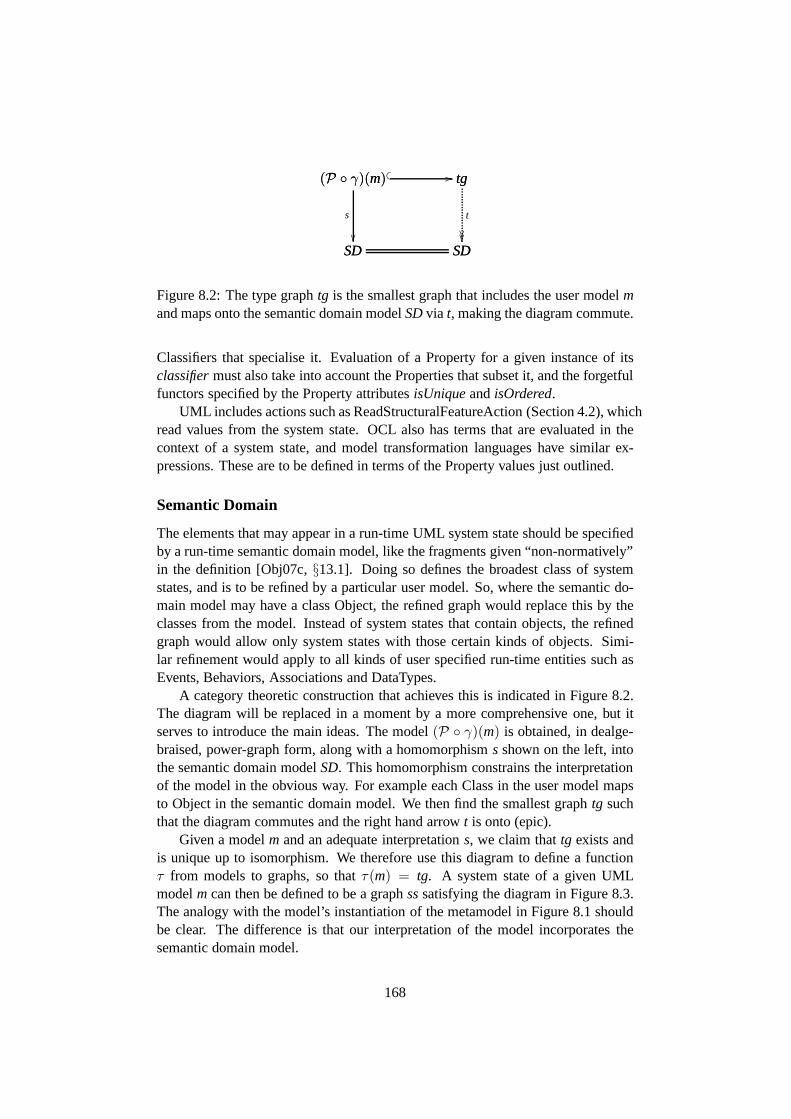
SD SD
(P ◦ γ)(m)
SD
s
��
(P ◦ γ)(m) tg� � // tg
SD
t
����
Figure 8.2: The type graphtg is the smallest graph that includes the user modelmand maps onto the semantic domain modelSDvia t, making the diagram commute.
Classifiers that specialise it. Evaluation of a Property fora given instance of itsclassifiermust also take into account the Properties that subset it, and the forgetfulfunctors specified by the Property attributesisUniqueandisOrdered.
UML includes actions such as ReadStructuralFeatureAction(Section 4.2), whichread values from the system state. OCL also has terms that areevaluated in thecontext of a system state, and model transformation languages have similar ex-pressions. These are to be defined in terms of the Property values just outlined.
Semantic Domain
The elements that may appear in a run-time UML system state should be specifiedby a run-time semantic domain model, like the fragments given “non-normatively”in the definition [Obj07c,§13.1]. Doing so defines the broadest class of systemstates, and is to be refined by a particular user model. So, where the semantic do-main model may have a class Object, the refined graph would replace this by theclasses from the model. Instead of system states that contain objects, the refinedgraph would allow only system states with those certain kinds of objects. Simi-lar refinement would apply to all kinds of user specified run-time entities such asEvents, Behaviors, Associations and DataTypes.
A category theoretic construction that achieves this is indicated in Figure 8.2.The diagram will be replaced in a moment by a more comprehensive one, but itserves to introduce the main ideas. The model(P ◦ γ)(m) is obtained, in dealge-braised, power-graph form, along with a homomorphisms shown on the left, intothe semantic domain modelSD. This homomorphism constrains the interpretationof the model in the obvious way. For example each Class in the user model mapsto Object in the semantic domain model. We then find the smallest graphtg suchthat the diagram commutes and the right hand arrowt is onto (epic).
Given a modelm and an adequate interpretations, we claim thattg exists andis unique up to isomorphism. We therefore use this diagram todefine a functionτ from models to graphs, so thatτ(m) = tg. A system state of a given UMLmodelm can then be defined to be a graphsssatisfying the diagram in Figure 8.3.The analogy with the model’s instantiation of the metamodelin Figure 8.1 shouldbe clear. The difference is that our interpretation of the model incorporates thesemantic domain model.
168

m → ssiss // τ(m)
Figure 8.3: A system state of a UML model is a graph that both contains and in-stantiates the model (where the interpretation functionτ(m) is temporarily definedby tg in the diagram of Figure 8.2.)
MM
m
� _
��
ss τ(m)iss
//
m
ss
� _
��
m (P ◦ γ)(MM)im // (P ◦ γ)(MM)
τ(m)
� _
��τ(m)
SD����
MM
SD
S
..
Figure 8.4: Abstract syntax and static semantics defined.
Combining the diagrams of Figures 8.1, 8.2 and 8.3, we obtaina diagram whichcompletely defines the abstract syntax and static semanticsof the language. Thisdiagram is shown in Figure 8.4.
On the left hand side we have the traditionalM2 M1 M0 hierarchy, with thehigher levels included in the lower. TheM3 instantiation is the composite of theinclusionMM → mandim (the top-most “L” in the diagram). Thus the metameta-model is the decoded form of the metamodel. The horizontal arrows are the explicitinstantiations given byinstanceOfedges in the graph,im being the model’s instan-tiation of the metamodel,iss the system state’s instantiation of the model.
The morphismS maps metamodel elements to the semantic domain elementsthat their instances represent. It is only partial, becausemany model elements suchas Actions do not have run-time counterparts, and others like Properties are nodesin the model but edges in the system state. Nevertheless, we expect that this partialmap is enough to ensure that the nodes that instantiate modelelements are the kindsof run time elements they are intended to be. This seems a natural way to definethe semantic mapping from metamodel elements to semantic domain elements.
We conjecture that the graphτ(m) is determined up to isomorphism by itscontext in this diagram. It contains the dealgebraised model and maps onto the se-
169
mantic domain modelSD. It is thus an augmentation of the included dealgebraisedmodel, adding run-time notions such as event occurrences (Section 5.3), enabledactions (Section 5.6) and so on.
Note thatMM, SD, SandP◦γ could be replaced with other graphs, partial mor-phisms and interpretation functions, to yield a definition of a different language. Avery practical possibility would be to define a new abstract syntax, but map it intothe same semantic domain as UML, yielding a domain specific language compat-ible with UML. Another possibility is to augment the semantic domain model toinclude concepts needed for a new application, then apply this diagram to defineUML over the new semantic domain.
Prescriptive Dynamics
How a UML system can evolve is defined by a transition relationover the classof system state graphs defined above. Graph transformation rules should be givenfor each kind of evolution step. One for each of the 36 concrete actions [Obj07c,§11] such as CreateObjectAction and ReadStructuralFeatureAction, plus rules forthe various kinds of causation such as procedure invocationand signal acceptance(Section 5.5). Thus what can happen is determined by the objects, their enabled ac-tions and their event pools. Since UML is intended to describe distributed systems,these rules ought to be applicable in parallel, where appropriate.
Descriptive Dynamics
One does not usually think of object diagrams as dynamic, buttheir intended mean-ing in the context of a larger model often has a dynamic element. Object diagramsare used for different purposes, sometimes just as an example, sometimes as aninitial state, sometimes as the desired outcome of a process. They could be used toexpress what must always eventually happen, what must neverhappen, what mustbe possible and so on. To express these modes formally, enabling automated se-mantic analysis, it is necessary to employ modal or temporaloperators. We developthis idea in the next section.
The model elements represented by an object diagram are converted into atoken graph by a functor similar to the one which decodes the class model. Theobject diagram is satisfied by a system state when a label and Class preservinghomomorphism exists from the token graphinto the system state (Section 3.6).
Interactions, as they are currently officially defined, worksimilarly to objectdiagrams. A graph can be extracted from the model which will have a homomor-phic image in the system state when the events it describes have happened (Section5.4). The exception, as we pointed out in that Section, is that some Interactionsinvolving deletion events are unsatisfiable even though thesequence of events theydescribe can happen. Like object diagrams, there are different ways in which anInteraction can be intended to constrain the model’s meaning, and these variationsrequire modal or temporal operators to be made precise. Furthermore, an alterna-
170
tive, bug-free definition of Interaction semantics could begiven using a temporallanguage over the UML transition system. The next section will outline this.
8.2 Towards a Well Defined and Understood UML
We set out to find a way to make the meaning of UML precise, a way that isfaithful to the existing language, supports clear definitions of development processideas such as refinement, is flexible enough to cope with profiles and semanticvariation points, and above all, improves people’s understanding of models. Wehave studied each of these requirements and the language itself and proposed theoutline of a definition.
This we hope is a step towards a world where analysts and theircustomers canconceptualise, explore and solve their problems without losing time and energygrappling with the tangle of ideas embodied in their modelling language. In thissection, we describe the remaining steps needed to reach such a utopia.
Completing the Definition
The first step is to actually complete the definition we have outlined. Due to thesize of the language and the need to support tools, this wouldneed to be a softwareexercise rather than a paper one. Dependence on theory and technology beyond theunderlying mathematics should be minimised.
In Section 4.2 we introduced a new kind of graph to accommodate the col-lection structures of UML’s static semantics. In order to define UML using theselist-graphs, we would require a theory of list-graph transformation systems. Wehave not defined this, and we have not formulated a suitable category of list-graphsin order to apply the general graph transformation theory of[EEPT06].
To facilitate independence from specific technologies, a good starting pointwould be to define a language for specifying graph transformation systems. Thiswould allow independent implementations to interchange specifications. Work hasbeen done on this [Tae01, Lam05], and the existing XML based language GTXLmight be suitable. A model transformation language such as Kermeta [IRI], orlower level tool such as XSLT [Cla99] could possibly be used to obtain the graphtransformation system definition from the metamodel and semantic domain model.
A modest but practical initial goal would be to mechanicallyestablish the con-sistency of a corrected version of the example from Chapters5 and 6 using animplementation of a partial definition. A simple way of doingthis would be toimplement the graph transformation system in the style of the HOL interactive the-orem prover [Har]. This has a datatype for theorems and each of the logical rulesare implemented as a function. The language ML [MTH90] used to implementHOL, was invented for this kind of syntactic rule system, andcode can be keptvery close to traditional mathematical definitions. We havefound using ML in thisway helps when developing formal systems because it provides interaction and it-
171

eration to the process. Model consistency could be demonstrated by constructingan initial state, confirming that it is correctly instantiated, then applying the stepsrepresented by the Interaction. We have undertaken work along these lines, but notwith great faithfulness to the existing definition.
A sequence of increasingly substantial example models could be tackled next,incorporating more and more of UML’s features and exploringpossible model exe-cutions until we are confident that the definition works and agrees with the informalofficial one.
ML programs are very close to HOL formulae, so the definition implementa-tion could be used to enable deductive verification. Perhapsit would be even betterto code the definition in HOL, then generate the ML code from there using thework of Berghofer and Nipkow [BN02]. In this way, we could prove properties ofthe system in general and be very confident that the results apply to the generatedimplementation1.
A Logic for UML
Discussions of logic are scattered throughout this study. Sections 1.1 and 1.3 gavea broad introduction to logic and its role in describing scientific models, and Sec-tion 6.1 introduced technical details of some actual logical systems. In Sections5.3 and 5.4 we found grave difficulties with Interactions as currently defined, andmentioned the idea of replacing that treatment with a temporal or dynamic logic.Chapter 6 formalised our example model using dynamic logic,and the conclusionof that chapter, Section 6.4, explored the proposal of logicfor Interactions in moredetail. Then Section 7.3 in our survey chapter reviewed several logic related con-tributions to the UML formalisation literature.
In Section 7.3 we identified three main roles for logic in UML:constraints,Interactions and tool support.
We have not given much consideration to UML’s existing constraint languageOCL, the logic-like language associated with UML. What status should we giveOCL? We could treat its existing informal definition as we have treated that ofUML, as something to be studied and faithfully made precise.Indeed, a formalsemantics appears, with “informative” status in the official definition [Obj06b, An-nex A]. Perhaps we should have used this as the starting pointfor the integratedsemantics?
However, there are other requirements for a logical language over the UMLsemantic domain. A modal or temporal logic could be used to repair the brokenInteraction semantics, as discussed in Section 5.4 and Chapter 6. We suggestedin Section 6.4 that UML’s dynamics would be defined by a graph transformationsystem, generated by a set of rules, one for each concrete action and one for eachkind of causation. The transitions in this system would be labelled by the names ofthese rules, along with the key participants in this particular application of the rule.
1Thanks to Michael Norrish for this idea.
172

Thus, these action/causation labels could be the atomic programs for a dynamiclogic, which would allow us to express Interactions in the style of Chapter 6, exceptover a faithful precise rendering of UML’s semantic domain.
The logic could have graphs as atomic propositions, which would be satisfiedby a system state iff they map homomorphically into it. Thus,the specific modelbeing considered could be asserted as a graphical axiom. These graphs would beexpressed as object diagrams for general system state expressions, or as any col-lection of UML diagrams for models. For example, we could then use the obviouspair of object diagrams to state that any employee who has a desk also has a chair.A body of work on “graphical constraints” has studied the useof graphs as propo-sitional atoms in temporal logics interpreted over graph transformation systems[HW95, GHK00].
A UML logic could also provide a basis for formal analysis techniques, espe-cially model checking, automated and semi-automated theorem proving. A lan-guage sufficiently expressive to state OCL-like constraints is bound to be unde-cidable. Useful results could be obtained in such a languageby interactive semi-automated theorem proving, but full automation will require abstraction or approx-imation. Fragments of logical languages often have less computationally complexdecision problems. To restrict a language is to abstract itssemantic domain, be-cause certain features can not be expressed and are thus effectively ignored. Muchof the study of logics is finding subsets of languages that canexpress useful state-ments, yet are computationally tractable. The sensible wayto proceed is to beginwith a language that can express everything likely to be needed, and then considerabstractions for specific purposes.
It will be important to find a syntax acceptable to developers. This is largelyindependent of the conceptual structure of the language. For example, the principleauthors of OCL responded to frequent complaints about its awkward syntax byproducing an alternate syntax similar to that of SQL [WK03, Appendix C] (Wediscussed SQL in Section 7.1). If we start with a “clean slate” and develop anexpressive language to fulfil these requirements, then muchof OCL could probablybe recovered as an alternate syntax for this language.
System development often begins with use cases, an idea incorporated intoUML. Development of a logic would also benefit from this approach. Below isa small selection of example formulae to guide us in identifying the required lan-guage features.
1. multiplicity constraints, eg.(∀ dog : Dog) | dog.owner |= 1
2. Interactions, see Section 6.2 (on Page 123). Also, the mode of assertionneeds to be expressed: this can happen, this can always happen, this willalways happen given this initial state, . . .
3. invariants, often relating associations, eg.(∀ x : X)x.a.b ⊆ x.c
4. safety propertyInit // �¬ Bad
173
5. liveness property, eg.AF(chocolate∨ refund) (The CTL path quantifierAFmeans every computation eventually reaches a state satisfying the argument)
We see that the logic will probably need variables and quantification. Whatshould these variables range over? In [BCG04], the variables range over hyper-edges. In our formulation, we would need quantification overnodes, as we saw inSection 6.4. Would we need to quantify over edges, or collections?
We have not discussed types in depth, but merely followed UML’s typing ideas,and the notion of a type-graph from graph transformation theory. The theory ofobject oriented typing systems is studied in [Bru02], and this work has been relatedto the UML setting in [SJ07]. Would there be value in a more elaborate typingsystem in the proposed logic?
Since UML allows concurrency, and this is supported by graphtransformation,
a single transition could be labelled with many concurrent actions, eg.Sa‖b // S′.
When evaluating the formula〈a〉P in stateS, would S′ |= P make this formulatrue? Many details like this would need working out.
The interaction of modalities and quantification is notoriously complicated[Fit99]. Consider the apparently simple sentence “everything is always good”.When we say “everything”, do we mean everything that exists now, or do we alsorequire that things that come into existence later are also good? When somethingceases to exist does it also cease to be “good”? Even predicates, such as “good”can be allowed to have different meanings at different points in time. Thus thereis another choice in interpreting our example sentence, do we mean “good” in thepresent sense, or does the meaning vary according to the states being considered.Fitting proposes a quantified modal logic which allows each of these choices tobe made explicit in the formula [Fit99]. He applies this to several well knownphilosophical problems, such as Frege’s puzzle about how “the morning star is theevening star” can be informative even though it is a tautology, and Russell’s at-tempt to find a truth value for “the king of France is bald”, even though there isno king of France. The domain of quantification in a UML systemis varying, nei-ther strictly increasing nor decreasing, which makes it a complicated case in termsof quantified modal logic. However, we see no need for predicate and functionssymbols to vary over time.
The key non-logical operation we see in the examples above isnavigation ofProperties, which we defined in Section 4.2. Generally, the result of evaluating aproperty for a given object is a collection, a list, bag, ordered set or set. Integrat-ing the theory of collections and Property navigation will be an important part ofdefining the logic.
As we have pointed out, the full logic is bound to be undecidable, and so frag-ments of the language, or abstractions over the semantic domain will be requiredfor automated tool support. Contributions proposing automated solutions to UMLverification problems routinely code up a partial approximation of some aspect ofUML into a formal language with tool support. What this amounts to is describing
174
a model of the model, but there is no systematic account of howthe result resem-bles the original. What questions can be reliably answered using the formalisation,and what information is lost or distorted? This suggests a theoretical question thatgoes well beyond UML, and to the very essence of modelling. Inany case, un-derstanding the preservation properties of the required abstractions would be muchmore feasible if the original semantic domain was preciselydefined, and a highlyexpressive reference language defined over it.
8.3 Findings
This section briefly summarises our findings.
Official Definition
Our detailed study and use of the official definition revealedthe following.
1. the official definition for UML 2.x [Obj07c] describes the semantics of thelanguage in enough detail to determine that some models are inconsistent(Chapter 5, especially Section 5.7)
2. the definition is very difficult to understand (Section 5.7)
3. many specific points require clarification (Section 5.7),and at least one as-pect of the language is incoherent (Section 5.4, the event-rot bug, see below)
4. the semantic domain described in the official definition closely resembles agraph transformation system (Sections 3.1, 5.6)
Definition Criteria
In Chapter 2, we argued for criteria for an improved definition of UML. They arebriefly summarised below
0. faithful to existing UML definition
1. understandableand implementable (supports agreement and tools)
2. definesconcrete syntax // abstract syntax // semantic domain
3. clarifies ideas: model consistency, model refinement, transformation sound-ness
4. reflective - objects can access their classes
5. flexible to support profiles and variations
175
Bootstrapping
1. the official definition is circular, using UML to define UML
2. we employ graphs in a bootstrapping process which recovers the intent ofthe official definition without circularity (Chapter 3, especially Sections 3.2and 3.6)
Dealgebraisation and Interpretation Functors
In Section 3.3, we introduce the dealgebraisation functor into the definition of in-stantiation. This has the following benefits.
1. recovers the intuition of an object diagram instantiating a class diagram,which is lost when we recognise the form of the class diagram fragmentof the model
2. enables a non-trivial account of self-instantiation, some models instantiatethemselves, but others do not
3. enables two or more levels of instantiation within the onegraph
4. non-trivial self instantiation and multiple levels of instantiation are also achievedin [GFB05], but the repository form of the model is lost, eg Properties areedges, not nodes
5. we suggest that other interpretation functors could select and transform therelevant model elements, giving a semantics by diagram type, the idea isexplored for object diagrams and sequence diagrams (Section 5.4)
Collections, Property Values and Association Symmetry
In Chapter 4 we develop a theory of Property values by building on the work ofDragan Milicev [Mil07].
1. we define a new kind of graph, thelist-graph, motivated by the need to rep-resent UML’s hierarchy of collection structures
2. many questions are left open on list-graphs, especially whether the graphtransformation theory of [EEPT06] can be applied to them
3. we develop a more uniform version of Milicev’s Property semantics, dis-pensing with ad-hoc treatment of ordered Properties
4. our account removes unwanted symmetry from association end annotations{union} and{subsetsx}
176
Semantic Domain Model and Type Graph Construction
Many authors define the space of system-states by using the model as a type-graph,but generally do not take into account the details of UML 2.x as officially defined.
1. we handle generalisation by composing a power-graph functor with the deal-gebraisation functor mentioned above (Section 3.3)
2. a subgraph of the power-graph is described to ensure correct instantiation ofsuper classes, but this should be formulated more carefullyand checked withsome examples
3. we propose a formal and “normative” role for (a possibly revised and en-larged version of) the non-normative semantic domain modelof [Obj07c,§13.1] (Section 5.3)
4. we give a construction of a type-graph from the model, the metamodel andthe semantic domain model (Section 8.1), examples and theoretical study areneeded to confirm that the construction works as intended
Descriptive Dynamics and the Event-Rot Bug
1. in Section 5.4 we discovered a bug in the semantics of Interactions: record-ing the history of the system in the system state fails when objects are deleted
2. it may be possible to correct this by distinguishing between deleted and “ex-isting” objects
3. however, we suggested replacing the “recorded history” approach by a dy-namic logic
Dynamic Logic
We found several reasons to consider using a dynamic logic aspart of UML’sdefinition, including the event-rot bug mentioned above. Webegan to investigatethis possibility (Section 6.4).
1. modalities are needed for practical uses of object diagrams, eg. this situationwill occur, always occurs, must not occur (Section 8.1)
2. OCL should be either properly defined or replaced
3. a definitive logic for UML would take the guesswork out of formalisationsfor logic based tool support such as model checking and deductive verifica-tion, much work remains to be done on this (Section 8.2)
177
8.4 Conclusion
Section 8.1 outlined our solution to the UML definition problem, a solution jus-tified by our sustained careful analysis of the language as currently defined. Theproblem was introduced in Chapter 1 where we noted that the lack of clarity inthe current definition is a serious drain on development productivity. Chapter 5provided evidence that the definition is indeed very unclear, but also that there ismeaning to be found there, to be expressed more clearly.
The test performed in Chapter 5 was to find the meaning given bythe offi-cial definition [Obj07c] to a tiny example model that appeared to be inconsistent.Preparations required for this test were extensive. In Chapter 2, we investigatedthe nature of modelling and UML style modelling languages, and determined whatwould be required from a good language definition. The resultwas our 6 Criteria,summarised in Table 7.1 (on Page 131). In order to talk sensibly about the model,we needed to find semantics for the fragment of UML used to define the abstractsyntax of UML. Chapter 3 looked to the definition for clues about the semanticdomain, and found that the core of the UML metamodel is the category used todefine edge-labelled graphs, and the usual intuitive interpretation of it mirrors thatmathematical definition. We were able to redevelop the ideasin the official defini-tion in a way that avoids its apparent circularity. The result was a graph theoreticrendering of a small static fragment of UML, including its semantics. That left afew tricky details to be sorted out in Chapter 4, in particular, an account of Prop-erty values that avoided unwanted symmetry of association end annotations, and aproper account of generalisation.
The point of Chapter 5 was not only to see whether the apparentinconsistencyof the example model was realised in the definition, but to guide us in a purpose-ful way through the definition, to develop a thorough understanding of the centralideas of UML. We are of course aware that UML was written by a committee, andhas evolved under an evolving committee, and can be expectedto be a little inco-herent conceptually. Nevertheless, core ideas did emerge,and fitted nicely with ourdiscovery early in Chapter 3 that the semantic domain described in the definitionlooks a lot like a graph. Even the descriptive dynamics of thelanguage seemed tobe rendered as graphs even though this turns out not to make good sense. Main-taining a recorded history of the system in each system stateas event occurrencesjoined to their participants has the fatal flaw that the record deteriorates as the par-ticipants do. Either the record must be separated from the actual participants, orthe descriptive dynamics should be expressed using a form oftemporal or dynamiclogic.
Our literature survey appears near the end of the dissertation, in Chapter 7,because we considered it necessary to understand what a gooddefinition is (Chap-ter 2), and what it is that needs to be defined (Chapter 5) before assessing candidatedefinitions. Chapter 6 is effectively part of this survey, because although it is ourown work, it comes from the period before the main ideas of thethesis. It soughtto use dynamic logic to define UML, by translating sets of diagrams into dynamic
178

logic formula. This enabled a tableau style search to test the model for consis-tency (satisfiability). However, our present interest in this work is its treatmentof Interactions as dynamic logic formulae. The conclusion of that chapter out-lines an alternative to the official approach based on this idea. In the survey chap-ter, database theory was presented as an example for UML to aspire to. Its clearand simple conceptual foundations have had clear technicalbenefits, but also aidsits understandability. Previous graph transformation work was surveyed, and wefound much good in the dynamic metamodelling approach [EHHS00]. The techni-cal aspects of our own work could be seen as a development of this theme, aligningit better with the ideas of the current official definition. Various other contributionswere considered, using various other techniques. Two of these works [Obe03] and[MB06, BCR07] stood out as faithful and plausible attempts to better define UML.We spent some time contemplating the lack of elegance noted by the authors ofthe second work, and suggested that what was needed was a simple mathematicalidea that captures the essence of the language. We believe that graphs and graphtransformation systems are the required structure.
In this concluding chapter, we summarised our findings, merging several re-lated partial definitions into a category theoretic commuting diagram in Figure 8.4which gives a modular and thus flexible definition of the abstract syntax and staticsemantics of UML. Further required work was outlined, in particular the develop-ment of a logic with the UML graph transformation system as its semantic domain.This logic would serve as a constraint language, to sensiblyformulate descriptivedynamics such as Interactions, and as a reference point for the abstractions andapproximations needed to provide automatic tool support for verification and vali-dation tasks.
We set out to find and justify a way to clearly, precisely and understandablydefine UML. As we saw in Chapter 7, almost every conceivable formal apparatushas been applied to UML, but we looked for the answer in the current definition,rather than the handbook for our favourite formal technology. We have found ananswer in graph transformation systems, which were unknownto us when we be-gan this search. Unsurprisingly, researchers have alreadyinvestigated the methodwe propose, but what we have achieved is a strong justification of this choice. Pro-posals for different solutions must now show that they better meet our criteria fromChapter 2, or challenge those criteria. Any claim that another formal system ismore faithful to UML as it is now defined must challenge our detailed analysis inChapters 3 to 5. Debate on these topics would advance the state of research, byfocusing it more clearly on the problem to be solved. Howeverwe hope that it willnot be necessary. We hope that we have convinced our readers,that UML wants tobe a graph transformation system.
179

Bibliography
[ABB+05] Wolfgang Ahrendt, Thomas Baar, Bernhard Beckert, RichardBubel, Martin Giese, Reiner Hhnle, Wolfram Menzel, WojciechMostowski, Andreas Roth, Steffen Schlager, and Peter H. Schmitt.The KeY tool.Software and System Modeling, 4(1):32–54, 2005.
[AFV01] Luca Aceto, Wan Fokkink, and Chris Verhoef.Handbook of Pro-cess Algebra, chapter Structural Operational Semantics, pages 197– 292. Elsevier, 2001.
[AG03] Pietro Abate and Rajeev Gore. System description: The tableauxworkbench. InTABLEAUX03: Automated Reasoning with AnalyticTableaux and Related Methods, number 2796 in LNAI, pages 230–236. Springer, 2003.
[Als64] William P. Alston. Philosophy of Language. Prentice-Hall, 1964.
[AR02] Egidio Astesiano and Gianna Reggio. An attempt at analysing theconsistency problems in the UML from a classical algebraic view-point. InWADT, pages 56–81, 2002.
[Baa03] Thomas Baar. Metamodels without metacircularities. L’Objet,9(4):95–114, 2003.
[BC95] Robert H. Bourdeau and Betty H.C. Cheng. A formal semanticsfor object model diagrams.IEEE Transactions on Software Engi-neering, 1995.
[BCG04] Paolo Baldan, Andrea Corradini, and Fabio Gadducci. Specifyingand verifying uml activity diagrams via graph transformation. InGlobal Computing. Springer, 2004.
[BCKL07] Paolo Baldan, Andrea Corradini, Barbara Konig, and Al-berto Lluch Lafuente. A temporal graph logic for verification ofgraph transformation systems. InRecent Trends in Algebraic De-velopment Techniques, number 4409 in LNCS. Springer, 2007.
180
[BCR04] Egon Borger, Alessandra Cavarra, and Elvinia Riccobene. On for-malizing uml state machines using asms.Information and SoftwareTechnology, 2004.
[BCR07] M. Broy, M. Cengarle, and B. Rumpe. Towards a system modelfor uml. part 2. the control model. Technical Report TUM-I0710,Munich University of Technology, 2007.
[Bec99] Kent Beck. Extreme Programming Exlained: Embrace Change.Addison-Wesley, 1999.
[Bec01] Bernhard Beckert. A dynamic logic for the formal verification ofjava card programs. InJava on Smart Cards: Programming andSecurity, number 2041 in LNCS, pages 6–24. Springer, 2001.
[Bel04] Alex E. Bell. Death by UML fever.Queue, 2(1):72–80, 2004.
[BF98] Jean-Michel Bruel and Robert B. France. Transforming UML mod-els to formal specifications. InProceedings of the OOPSLA’98Workshop on Formalising UML, 1998.
[BG01] Jean Bezivin and Olivier Gerbe. Towards a precise definition of theOMG/MDA framework. InASE ’01: Proceedings of the 16th IEEEinternational conference on Automated software engineering, page273, Washington, DC, USA, 2001. IEEE Computer Society.
[BG04] Fabian Buttner and Martin Gogolla. On generalization and over-riding in UML 2.0. In Octavian Patrascoiu, editor,OCL and ModelDriven Engineering, UML 2004 Conference Workshop, October12, 2004, Lisbon, Portugal, pages 1–15. University of Kent, 2004.
[BGG04] Hanna Bauerdick, Martin Gogolla, and Fabian Gutsche. DetectingOCL traps in the UML 2.0 superstructure: An experience report.In Thomas Baar, Alfred Strohmeier, Ana Moreira, and StephenJ.Mellor, editors, UML 2004 - The Unified Modelling LanguageModelling Languages and Applications. 7th International Confer-ence, Lisbon, Portugal., LNCS, pages 11–15. Springer, October2004.
[BH02] Luciano Baresi and Reiko Heckel. Tutorial introduction to graphtransformation: A software engineering perspective. InProceed-ings of the first International Workshop on Theory and Applicationof Graph Transformation, pages 402–429, 2002.
[BKS02] Bernhard Beckert, Uwe Keller, and Peter H. Schmitt.Translatingthe object constraint language into first-order predicate logic. InProceedings of VERIFY, Workshop at Federated Logic conferences(FLoC), 2002.
181
[BN98] Franz Baader and Tobias Nipkow.Term Rewriting and All That.Cambridge University Press, 1998.
[BN02] Stefan Berghofer and Tobias Nipkow. Executing higher order logic.In Types for Proofs and Programs (Types 2000), 2002.
[Boo94] Grady Booch.Object-oriented analysis and design with applica-tions. Addison-Wesley, 2nd edition, 1994.
[Bro87] Frederick P. Brooks, Jr. No silver bullet: Essence and accidents ofsoftware engineering.Computer, May 1987.
[BRST05] Jean Bezivin, Bernhard Rumpe, Andy Schur, andLaurence Tratt. Model transformations in prac-tice workshop, call for papers. web, July 2005.http://sosym.dcs.kcl.ac.uk/events/mtip05/long_cfp.p df .
[Bru02] Kim B. Bruce.Foundations of Object-Oriented Languages: Typesand Semantics. MIT Press, 2002.
[BS81] S. Burris and H. Sankappanavar.A Course in Universal Algebra.Springer Verlag, Berlin, 1981.
[Buz95] Tony Buzan.The Mind-Map Book. BBC Books, 2nd edition, 1995.
[BW90] Michael Barr and Charles Wells.Category Theory for ComputingScience. Prentice-Hall, 1990.
[BW02] Achim D. Brucker and Burkhart Wolff. A proposal for a formalOCL semantics in Isabelle/HOL. In V.A Carren no, C. Mu noz,and S. Tahar, editors,TPHOLS 2002, volume 2410 ofLNCS, pages99–114. Springer-Verlag, 2002.
[CEK01] Tony Clark, Andy Evans, and Stuart Kent. The metamodelling lan-guage calculus: Foundation semantics for UML. InFormal Aspectsof Software Engineering, volume 2029, pages 17–31. Springer-Verlag, 2001.
[CF05] M. Couzinier and L. Feraud. Formal verification of dynamic UMLdiagrams using TLA+. In Yu.I. Shokin and O.I. Potaturkin, editors,ACIT - Software Engineering. ACTA Press, 2005.
[CGHS00] K. Compton, Y. Gurevich, J. Huggins, and W. Shen. AnAuto-matic Verification Tool for UML. Technical Report CSE-TR-423-00, University of Michigan, 2000.
[Che76] P.P. Chen. The entity-relationship model: Toward aunified view ofdata.ACM on Database Systems, 1976.
182

[CHM00] Andrea Corradini, Reiko Heckel, and Ugo Montanari.Graphicaloperational semantics. InWorkshop on Graph Transformation andVisual Languages, 2000.
[CIO00] Cristiano Calcagno, Samin Ishtiaq, and Peter W. O’Hearn. Se-mantic analysis of pointer aliasing, allocation and disposal in hoarelogic. In PPDP ’00: Proceedings of the 2nd ACM SIGPLAN in-ternational conference on Principles and practice of declarativeprogramming, pages 190–201, New York, NY, USA, 2000. ACMPress.
[CK03] Marıa Victoria Cengarle and Alexander Knapp. Ocl 1.4/1.5 vs. 2.0expressions formal semantics and expressiveness.Software andSystem Modeling, 2003.
[Cla99] James Clark. XSL transformations (XSLT). Technical report,W3C, 1999. (viewed 8 May 2008).
[Cod70] E. Codd. A relational model for large shared data banks. Commu-nications of the ACM, 1970.
[Dav01] Martin Davis. Engines of Logic: Mathematicians and the Originof the Computer. W. W. Norton & Company, 2001.
[DBB+91] A Delridge, JRL Bernard, D Blair, P Peters, and S Butler, editors.The Macquarie Dictionary. The Macquarie Library, 2nd edition,1991.
[DeM78] Tom DeMarco. Structured Analysis and System Specification.Yourdon Press, 1978.
[DGHP99] M D’Agostino, D Gabbay, R Haehnle, and J Posegga, edi-tors. Handbook of Tableau Methods, chapter Tableau methodsfor modal and temporal logics, by Rajeev Gore. Kluwer, 1999.http://rsise.anu.edu.au/ ˜ rpg/Publications/Handbook-Tableau-Metho
[DGR+05] Islay Davies, Peter Green, Michael Rosemann, Marta Indulska, andStan Gallo. How do practitioners use conceptual modeling inprac-tice? Data and Knowedge Engineering, 2005.
[Dis98] Zinovy Diskin. The arrow logic of meta-specifications: a formal-ized graph-based framework for structuring schema repositories.In OOPSLA workshop on behavioral semantics for OO, 1998.
[Dis01] Zinovy Diskin. On modeling, mathematics, categorytheory andrm-odp. InWorkshop on Open Distributed Processing: EnterpriseComputation, Knowledge, Engineering and Realization (WOOD-PECKER, 2001.
183

[Dis03] Zinovy Diskin. Mathematics of UML: Making the Odysseys ofUML less dramatic, volume Practical Foundations of Business Sys-tem Specifications, chapter 8. Kluwer, 2003.
[DJPV03] Werner Damm, Bernhard Josko, Amir Pnueli, and Angelika Votint-seva. Understanding UML: A formal semantics of concurrencyandcommunication in real-time UML. InFormal Methods for Com-ponents and Objects, Proceedings 2002, volume 2852 ofLNCS.Springer, 2003.
[DM95] Fran cois-Nicola Demers and Jacques Malenfant. Reflection inlogic, functional and object-oriented programming: a short com-parative study. InProc. of the IJCAI95 Workshop on Reflectionand Metalevel Architectures and their Applications in AI, 1995.
[DN66] Ole-Johan Dahl and Kristen Nygaard. Simula: an algol-based sim-ulation language.Commun. ACM, 9(9):671–678, 1966.
[Ecl07] UML2: EMF-based UML 2.x Metamodel Implementation, 2007.http://www.eclipse.org/uml2 .
[EEE+07] Hartmut Ehrig, Karsten Ehrig, Claudia Ermel, Frank Hermann,and Gabriele Taentzer. Information preserving bidirectional modeltransformations. InFundamental Approaches to Software Engi-neering, 2007.
[EEPT06] Harmut Ehrig, Karsten Ehrig, Ulrike Prange, and GabrieleTaentzer. Fundamentals of Algebraic Graph Transformation.Springer, 2006.
[EHHS00] Gregor Engels, Jan Hendrik Hausmann, Reiko Heckel, and StefanSauer. Dynamic meta modeling: A graphical approach to the oper-ational semantics of behavioural diagrams in UML. InProceedingsof UML, volume 1939. LNCS, 2000.
[EHHS02] Gregor Engels, Jan Hendrik Hausmann, Reiko Heckel, and StefanSauer. Testing the consistency of dynamic UML diagrams.Inte-grated Design and Process Technology, 2002.
[EKHG02] Gregor Engels, Jochen M. Kuster, Reiko Heckel, and Luuk Groe-newegen. Towards consistency-preserving model evolution. InWorkshop on Principles of Software Evolution, 2002.
[EN07] Ramez Elmasri and Shamkant B. Navathe.Fundamentals ofDatabase Systems. Addison-Wesley, 5th edition, 2007.
[ES95] Gregor Engels and Andy Schurr. Encapsulated hierarchical graphs,graph types and meta types. InWorkshop on Graph Rewriting andComputation, 1995.
184
[ESW07] Gregor Engels, Christian Soltenborn, and Keike Werheim. Anal-ysis of uml activities using dynamic meta modeling. InFor-mal Methods for Open Object-Based Distributed Systems, LNCS.Springer, 2007.
[EW01] Joerg Evermann and Yair Wand. Towards ontologicallybasedsemantics for uml constructs. InConceptual Modeling - ER.Springer, 2001.
[FB05] Frdric Fondement and Thomas Baar. Making metamodelsawareof concrete syntax. InECMDA-FA, pages 190–204, 2005.
[FGDTS06] Robert B. France, Sudipto Ghosh, Trung Dinh-Trong, and ArnorSolberg. Model-driven development using UML 2.0: Promisesandpitfalls. Computer, 39(2):59, 2006.
[FH06] Roman Frigg and Stephan Hartmann. Models in science.In Ed-ward N. Zalta, editor,The Stanford Encyclopedia of Philosophy.Spring 2006.
[Fit99] Melvin Fitting. On quantified modal logic.Fundamenta Informat-icae, 1999.
[GFB05] Martin Gogolla, Jean-Marie Favre, and Fabian Buttner.On squeezing m0, m1, m2, and m3 into a single ob-ject diagram. In OCL 2005 @ MODELS 2005, 2005.http://www-adele.imag.fr/ ˜ jmfavre/papers/OnSqueezingM0M1M2AndM3I
[GGJZ00] Carl A. Gunter, Elsa L. Gunter, Michael Jackson, and Pamela Zave.A reference model for requirements and specifications.IEEE Soft-ware, 2000.
[GGL05] Lars Grunske, Leif Geiger, and Michael Lawley. A graphical spec-ification of model transformations with triple graph grammars. InProceedings of the European Conference on Model Driven Archi-tecture, number 3748 in LNCS. Springer, 2005.
[GHJV95] Erich Gamma, Richard Helm, Ralph Johnson, and JohnVlis-sides. Design patterns: elements of reusable object-oriented soft-ware. Addison-Wesley Longman Publishing Co., Inc., Boston,MA, USA, 1995.
[GHK00] Fabio Gadducci, Reiko Heckel, and Manuel Koch. A fully abstractmodel for graph-interpreted temporal logic. InTheory and Appli-cations of Graph Transformation, number 1764 in LNCS. Springer,2000.
185

[Gie88] R Giere.Explaining science: a cognitive approach. Chicago Uni-versity Press, 1988.
[Gog92] Joseph A. Goguen. Sheaf semantics for concurrent interacting ob-jects. Mathematical Structures in Computer Science, 2(2):159–191, 1992.
[Gro08] Object Management Group. Omg formally re-leased versions of uml. web, viewed 22 June 2008.http://www.omg.org/spec/UML/ .
[GS06] Peter Godfrey-Smith. The strategy of model-based science. Biol-ogy and Philosophy, 2006.
[Gur95] Yuri Gurevich. Evolving algebras 1993: Lipari guide. In E. Borger,editor, Specification and Validation Methods. Oxford UniversityPress, 1995.
[Gur99] Corin A. Gurr. Effective diagrammatic communication: Syntactic,semantic and pragmatic issues.Journal of Visual Languages andComputing, 10(4):317–342, 1999.
[GZK02] Martin Gogolla, Paul Ziemann, and Sabine Kuske. Towards anintegrated graph based semantics for UML.Electr. Notes Theor.Comput. Sci., 72(3), 2002.
[Har] John Harrison. The HOL Light Manual. Univer-sity of Cambridge Computer Laboratory, 1.1 edition.http://www.cl.cam.ac.uk/users/jrh/hol-light .
[Hau05] Jan Hausmann.Dynamic Meta Modeling. PhD thesis, Faculty ofComputer Science, Electrical Engineering, and Mathematics of theUniversity of Paderborn, 2005.
[HKT00] David Harel, Dexter Kozen, and Jerzy Tiuryn.Dynamic Logic.MIT Press, 2000.
[HM07] David Harel and Shahar Maoz. Assert and negate revisited: Modalsemantics for UML sequence diagrams.Software and SystemsModeling, 2007.
[Hoa85] C.A.R. Hoare. Communicating Sequential Processes. Prentice-Hall, 1985.
[Hod97] Wilfrid Hodges. A Shorter Model Theory. Cambridge UniversityPress, 1997.
186
[HR04] David Harel and Bernhard Rumpe. Meaningful modeling: What’sthe semantics of ”semantics”?Computer, pages 64–72, October2004.
[HS05] Brian Henderson-Sellers. UML - the good, the bad or the ugly?perspectives from a panel of experts.Software and System Model-ing, 4(1):4–13, 2005.
[HW95] Reiko Heckel and Annika Wagner. Ensuring consistency of condi-tional graph grammars - a constructive approach. InWorkshop onGraph Rewriting and Computation, 1995.
[IRI] IRISA Project Triskell. Kermeta: Triskell metamodeling kernel.web. http://www.kermeta.org .
[J+92] Ivar Jacobson et al.Object-Oriented Software Engineering: A UseCase Driven Approach. Addson-Wesley, 1992.
[JRB05] Ivar Jacobson James Rumbaugh and Grady Booch.The UnifiedModeling Language Reference Manual. Addison Wesley, 2nd edi-tion, 2005.
[KBC05] Soon-Kyeong Kim, Damian Burger, and David A. Carrington. AnMDA approach towards integrating formal and informal modelinglanguages. InFM, pages 448–464, 2005.
[KC00] Soon-Kyeong Kim and David A. Carrington. A formal mappingbetween UML models and object-Z specifications. InProceedingsof the First International Conference of B and Z Users on FormalSpecification and Development in Z and B, pages 2–21, 2000.
[KER99] S. Kent, A. Evans, and B. Rumpe. UML semantics FAQ. InA. Moreira and S. Demeyer, editors,Object-Oriented Technology,ECOOP’99 Workshop Reader. LNCS 1743, Springer Verlag, 1999.
[KG01] Ralf Kollmann and Martin Gogolla. Capturing dynamicprogrambehavior with UML collaboration diagrams. InCSMR ’01: Pro-ceedings of the Fifth European Conference on Software Mainte-nance and Reengineering, page 58, Washington, DC, USA, 2001.IEEE Computer Society.
[KGR99] S. Kent, S. Gaito, and N. Ross.Behavioral Specifications of Busi-nesses and Systems, chapter A Metamodel semantics for structuralconstraints in UML. Kluwer, 1999.
[KS03] Jochen M. Kuster and Jan Stehr. Towards explicit behavioral con-sistency concepts in the UML. InWorkshop on Scenario and StateMachines: Models, Algorithms and Tools, 2003.
187
[Kuh06] Thomas Kuhne. Matters of (meta-) modeling.Software SystemModeling, 2006.
[Lam05] Leen Lambers. A new version of gtxl : An exchange format forgraph transformation systems. InProceedings of the InternationalWorkshop on Graph-Based Tools (GraBaTs 2004), 2005.
[Lig91] David Lightfoot. Formal Specification Using Z. Macmillan, 1991.
[LS86] J. Lambek and P.J. Scott.Introduction to Higher Order CategoricalLogic. Cambridge University Press, 1986.
[Mac98] Saunders MacLane.Categories for the Working Mathematician.Number 5 in Graduate Texts in Mathematics. Springer, 2nd edition,1971, 1998.
[MB02] Stephen J. Mellor and Marc J. Balcer.Executable UML, A Foun-dation for Model-Driven Architecture. Object Technology Series.Addison-Wesley, 2002.
[MB06] B. Rumpe M. Broy, M. Cengarle. Towards a system model for uml.the structural data model. Technical Report TUM-I0612, MunichUniversity of Technology, 2006.
[MC01] William E. McUmber and Betty H.C. Cheng. A general frameworkfor formalizing UML with formal languages. InProceedings of the23rd International Conference on Software Engineering (ICSE),2001.
[Mel03] Stephen J. Mellor. A framework for aspect-orientedmodelling. InThe 4th AOSD Modeling With UML Workshop, 2003.
[Mic] Microsoft. Spec explorer. web viewed 30 April 2008.http://research.microsoft.com/specexplorer/ .
[Mil06] D. Milicev. On the semantics of associations and association endsin UML. Technical report, University of Belgrade, School ofElec-trical Engineering, February 2006.
[Mil07] D. Milicev. On the semantics of associations and association endsin UML. IEEE Transactions on Software Engineering, 2007.
[MLL02] Huaikou Miao, Ling Liu, and Li Li. Formalizing UML modelswith object-z. InICFEM, pages 523–534, 2002.
[MM92] Saunders MacLane and Ieke Moerdijk.Sheaves in Geometry andLogic: a first introduction to topos theory. Springer, 1992.
188
[MM03] Joaquin Miller and Jishnu Mukerji. MDA guide.Technical report, Object Management Group, 2003.http://www.omg.org/mda .
[MOSS99] Markus Muller-Olm, David Schmidt, and Bernhard Steffen.Model-checking a tutorial introduction. InInternational Sympo-sium on Static Analysis, number 1694 in LNCS. Springer, 1999.
[MTH90] Robin Milner, Mads Tofte, and Robert Harper.The Definition ofStandard ML. MIT Press, 1990.
[Mun86] Brent Mundy. On the general theory of meaningful representation.Synthese, 1986.
[Myl80] John Mylopoulos. A perspective for research on conceptual mod-elling. In Proceedings of the 1980 workshop on Data abstraction,databases and conceptual modeling, pages 167–170, New York,NY, USA, 1980. ACM Press.
[Myl98] John Mylopoulos. Information modeling in the time of the revolu-tion. Information Systems, 1998.
[Nag61] Thomas Nagel.The Structure of Science. Routledge & Kegan Paul,1961.
[Nag76] Manfred Nagl. Formal languages of labelled graphs.Computing,16(1-2):113–137, 1976.
[Obe03] Ileana Ober. An asm semantics of UML derived from themeta-model and incorporating actions. InAbstract State Machines, num-ber 2589 in LNCS. Springer, 2003.
[Obj] Object Management Group. Issues forthe UML 2 revision task force. web.http://www.omg.org/issues/uml2-rtf.html .
[Obj05] Object Management Group. Unified modeling language: Super-structure. Technical report, Object Management Group, 2005.http://www.omg.org/docs/formal/05-07-04.pdf .
[Obj06a] Object Management Group. Meta object facility (MOF) 2.0 corespecification. Technical report, Object Management Group,2006.http://www.omg.org/docs/formal/06-01-01.pdf .
[Obj06b] Object Management Group. OCL 2.0 specification.Technical report, Object Management Group, 2006.http://www.omg.org/docs/formal/06-05-01.pdf .
189

[Obj07a] Object Management Group. UML 2.1.1 infrastructure speci-fication. Technical report, Object Management Group, 2007.http://www.omg.org/docs/formal/07-02-04.pdf .
[Obj07b] Object Management Group. Unified modelinglanguage: Superstructure, version 2.1.1. Tech-nical report, Object Management Group, 2007.http://www.omg.org/docs/formal/07-02-03.pdf .
[Obj07c] Object Management Group. Unified modelinglanguage: Superstructure, version 2.1.2. Tech-nical report, Object Management Group, 2007.http://www.omg.org/docs/formal/07-11-01.pdf .
[Obj09] Object Management Group. Unified modelinglanguage: Superstructure, version 2.2. Tech-nical report, Object Management Group, 2009.http://www.omg.org/docs/formal/09-02-03.pdf .
[O’K06a] Greg O’Keefe. Dynamic logic for UML consis-tency. In ECMDA-FA, European Conference on ModelDriven Architecture, number 4066 in Lecture Notesin Computer Science, pages 113–127. Springer, 2006.http://rsise.anu.edu.au/ ˜ okeefe/dl4uml.pdf .
[O’K06b] Greg O’Keefe. Improving the definition of UML. InProceedingsof the ACM/IEEE 9th International Conference on Model DrivenEngineering Languages and Systems (MoDELS), number 4199 inLecture Notes in Computer Science, pages 42–56. Springer, 2006.http://rsise.anu.edu.au/ ˜ okeefe/improvingUML.pdf .
[PC05] Jeffrey Parsons and Linda Cole. What do the pictures mean? guide-lines for experimental evaluation of representation fidelity in dia-grammatical conceptual modeling techniques.Data and Knowl-edge Engineering, 2005.
[Pel87] David Peleg. Concurrent dynamic logic.Journal of the ACM,34(2):450–479, April 1987.
[Pie91] Benjamin C. Pierce.Basic Category Theory for Computer Scien-tists. MIT Press, 1991.
[Plo81] Gordin Plotkin. A structural approach to operational semantics.Technical Report DAIMI FN-19, Aarhus University, 1981.
[PN] Larry Paulson and Tobias Nipkow. Isabelle.http://isabelle.in.tum.de .
190

[RB88] D.E. Rydeheard and R.M. Burstall.Computational Category The-ory. Prentice Hall, 1988.
[RBD05] Iris Reinhartz-Berger and Dov Dori. OPM vs. UML - experiment-ing with comprehension and construction of web applicationmod-els. Empirical Software Engineering, 10(1):57–80, 2005.
[RBP+91] James Rumbaugh, Michael Blaha, William Premerlani, FrederickEddy, and William Lorensen.Object-Oriented Modeling and De-sign. Prentice-Hall, 1991.
[RCA01] Gianna Reggio, Maura Cerioli, and Egidio Astesiano. Towards arigourous semantics of UML supporting its multiview approach.In H. Hussmann, editor,FASE 2001, volume 2029 ofLNCS, pages171–186. Springer, 2001.
[REE+99] G. Rozenberg, H. Ehrig, G. Engels, H.J. Kreowski, and U. Mon-tanari, editors.Handbook of graph grammars and computing bygraph transformation, volume I, II and III. World Scientific, 1997,1999.
[Ren03] A. Rensink. The groove simulator: A tool for state space genera-tion. In Proc. Application of Graph Transformations with Indus-trial Relevance (AGTIVE ’03). Springer, 2003.
[RG01] M. Richters and M. Gogolla. Ocl - syntax, semantics and tools.In T. Clark and J. Warmer, editors,Advances in Object Modellingwith the OCL, number 2263. Springer, 2001.
[Rob96] Abraham Robinson.Non-Standard Analysis. Princeton UniversityPress, 1996.
[Ros77] D. Ross. Structured analysis: A language for communicating ideas.IEEE Transactions on Software Engineering, 1977.
[RRGI06] Jan Recker, Michael Rosemann, Peter Green, and Marta Indulska.Extending the scope of representation theory: A review and pro-posed research model. In3rd Biannual ANU Workshop on Infor-mation Systems Foundations, 2006.
[RS04] E. Riccobene and P. Scandurra. Towards an interchange languagefor asms. InAbstract State Machines: Advances in Theory andPractice. Springer, 2004.
[Rus21] Bertrand Russell.The Analysis of Mind. George Allen & Unwin,1921.
191

[RW03] Holger Rasch and Heike Wehrheim. Checking consistency in UMLdiagramms: Classes and state machines. InFMOODS, pages 229–243, 2003.
[Sch96] David A. Schmidt. Programming language semantics.ACM Com-put. Surv., 28(1):265–267, 1996.
[Sei03] Ed Seidewitz. What models mean.IEEE Softw., 20(5):26–32,2003.
[Sel01] Bran Selic. Specification and modeling: An indus-trial perspective. In Proceedings of the 23rd Interna-tional Conference on Software Engineering. IEEE, 2001.http://csdl.computer.org/comp/proceedings/icse/2001 /1050/00/1050
[Sel03] Bran Selic. The pragmatics of model-driven development. IEEESoftware, 2003.
[Sel04] Bran V. Selic. On the semantic foundations of standard UML 2.0.In Marco Bernardo and Flavio Corradini, editors,Formal Meth-ods for the Design of Real-Time Systems: International School onFormal Methods for the Design of Computer, Communication, andSoftware Systems, number 3185 in LNCS, 2004.
[SJ07] Jim Steel and Jean-Marc Jezequel. On model typing.Software andSystems Modelling, 2007.
[SM88] Sally Shlaer and Stephen J. Mellor.Object Oriented Systems Anal-ysis: Modeling the World in Data. Yourdon Press, 1988.
[SM92] Sally Shlaer and Stephen J. Mellor.Object Lifecycles: Modelingthe World in States. Yourdon Press, 1992.
[Som01] Ian Sommerville.Software Engineering. Addison Wesley, 6th edi-tion, 2001.
[Spi92] J.M. Spivey. The Z Notation: A Reference Man-ual. Prentice-Hall, 2nd edition, 1989, 1992.http://spivey.oriel.ox.ac.uk/mike/zrm/zrm.pdf .
[Sup60] Patrick Suppes. A comparison of the meaning and usesof modelsin mathematics and the empirical sciences.Synthese, 1960.
[Tae01] Gabriele Taentzer. Towards common exchange formats for graphsand graph transformation systems. InUniform Approaches toGraphical Process Specification Techniques, 2001.
192
[TAKPvdZ04] J. Hooman T. Arons, H. Kugler, A. Pnueli, and M. van der Zwaag.Deductive verification of UML models in tlpvs. InProceedingsUML, 2004.
[Tar41] Alfred Tarski. On the calculus of relations.Journal of SymbolicLogic, 6:73–89, 1941.
[TC] Borland TogetherSoft Corporation. Together control centre. Web.http://www.borland.com/us/products/together ,viewed 28 June 2008.
[TE00] Aliki Tsiolakis and Hartmut Ehrig. Consistency analysis of UMLclass and sequence diagrams using attributed graph grammars.In Proc. of Joint APPLIGRAPH/GETGRATS Workshop on GraphTransformation Systems, 2000.
[UA03] Axel Uhl and Scott W. Ambler. Point/counterpoint: Model drivenarchitecture is ready for prime time / agile model driven develop-ment is good enough.IEEE Software, 20(5):70–73, 2003.
[vEHN01] Jan van Eijck, Juan Heguiabehere, and BreanndanO Nuallain.Tableau reasoning and programming with dynamic first order logic.Logic Journal of the IGPL, 2001.
[VF80] B. Van Fraassen.The Scientific Image. Clarendon Press, Oxford,1980.
[VP02] Daniel Varro and Andras Pataricza. Metamodelingmathematics:A precise and visual framework for describing semantics domainsof UML models. InUML ’02: Proceedings of the 5th Interna-tional Conference on The Unified Modeling Language, pages 18–33, London, UK, 2002. Springer-Verlag.
[WB97] Roel Wieringa and Jan Broerson. Minimal transition system se-mantics for lightweight class and behaviour diagrams. In ManfredBroy, Derek Coleman, Tom S. E. Maibaum, and Bernhard Rumpe,editors,Proceedings PSMT’98 Workshop on Precise Semantics forModeling Techniques. Technische Universitaet Muenchen, TUM-I9803, April 1997.
[Wik06] Wikipedia. Underpinning. web, 2006.http://en.wikipedia.org/wiki/Underpinning .
[Wir90] Martin Wirsing. Algebraic specification, pages 675–788. MITPress, Cambridge, MA, USA, 1990.
[WK03] Jos Warmer and Anneke Kleppe.The Object Constraint Language:Getting Your Models Ready for MDA. Addison-Wesley, 2003.
193

[WS96] R.J. Wieringa and G. Saake. A formal analysis of the Shlaer-Mellormethod: Towards a toolkit of formal and informal requirementsspecification techniques.Requirements Engineering, pages 106–131, 1996.
[XLB01] Fei Xie, Vladimir Levin, and James C. Browne. Model check-ing for an executable subset of UML. InProceedings of the IEEEConference on Automated Software Engineering, pages 333–336,2001.
[ZHG05] Paul Ziemann, Karsten Holscher, and Martin Gogolla. From UMLmodels to graph transformation systems.Electr. Notes Theor. Com-put. Sci., 127(4):17–33, 2005.
[ZJ97] Pamela Zave and Michael Jackson. Four dark corners ofrequire-ments engineering.ACM Transactions on Software Engineeringand Methodology, 1997.
194