the metal master machine tool - model · pdf filethe metal master machine tool ... and end...
TRANSCRIPT

Metal Master – Design & Construction Notes (W. D. Urwick - 1983)
Page 1 of 52
The Metal Master Machine Tool
Designed by - W. D. Urwick
Introduction
Once in a while someone designs something really innovative which at first sight you would think
it would take the world by storm. Sadly because of entrenched viewpoints, vested interest and
maybe a lack of marketing skills such good ideas do not always achieve the recognition they
deserve.
The Metal Master Machine tool by David Urwick is one such innovation. It is still not clear to us
why this idea did not take off. The machine is ideal for the small home machinist workshop and
would avoid the somewhat larger investment in cash and the space required for multiple machines
to achieve the same manufacturing capability.
So in a tribute to the man who designed the machine we have produced a set of documentation to
enable anyone to reproduce the machine. Some people who recognize the design for what it is have
gone to the trouble to produce a set of castings for the major components and got part way through
a build programme for their own version of the machine. Others have used the drawings to develop
their own modern version of the machine (e.g. Alan Jackson’s Stepperhead).
History of the design, drawings and manufacturing notes.
The design was originally conceived in the early 1950s by David Urwick. The design was
documented at the time and revisions made resulting in the hand drawn manufacturing set included
with these notes was finalized in the 1980s.
Unfortunately, information, materials and documentation related to sporadic documentation efforts
have appeared and disappeared on a number of websites over the past dozen years or so. It is hoped
that by pulling the various sources of information together and giving it some structure we may
encourage more to have a go at making and building this truly unique machine.

Metal Master – Design & Construction Notes (W. D. Urwick - 1983)
Page 2 of 52
The design was certainly revolutionary and it was used as a basis for the larger LabourMill
machine. That machine was marketed for the small jobbing machine shop or as a millwright’s
machine tool.
On that basis the Urwick’s Metalmaster should make an ideal machine for the model and
experimental engineer. However, things mostly never turn into an ideal solution without luck,
money and persistence. Remember how Dyson had to fight like crazy to ensure his designs weren’t
either rubbished or ripped off by someone else.
Urwick included in his machine many simple ideas that should have put it at the top of its chosen
market. So remembering that not always do the fastest win the race nor the mightiest win the battle,
we submit these manufacturing notes for the Urwick machine for anyone’s scrutiny so they can
utilise some of David’s ideas or make a replica of the machine themselves.
Some have said the cost of the patterns for the castings might be prohibitive. Perhaps the use of
expanded polystyrene as expendable patterns would make that easier. Production using hot knife or
3D CNC might be the way to go.
Our effort to understand the design of this machine has been the building of a 3D CAD model,
some images of which appear in this collection of notes, drawings and images.
We acknowledge that work done by others is greater than ours and if we have reproduced
information without proper acknowledgement please let us know and we will correct the errors and
omissions.
Other descriptions of the Metal Master and some of its machine elements appeared in the following
editions of the Model Engineer.
A Free-Lance Lathe by W. D. Urwick Model Engineer - 1
st March 1951
A REVOLUTIONARY LATHE by W.D. Urwick Model Engineer 4
th January 1974
A KEYWAY BREAKTHROUGH by David Urwick Model Engineer - 15
th August 1980
METALMASTER - A Zero Taper Machine Tool - by David Urwick Model Engineer 2
nd July 1982
Metal Master – Design & Construction Notes (W. D. Urwick - 1983)
Page 3 of 52
Mick Colins, who bought David’s own original machine, agreed with David Urwick’s widow that
the drawings should be made public and that each user of the drawings would make a small
donation to her for doing so. It is not clear how the donation was to be made for this “shareware.”
Later a member of the yahoo group re-created the core set of drawings as 2D dxf files and posted
them for the group. Another member of the group made expanded polystyrene patterns to enable a
set of castings to be made by the lost foam process. Some of those images have been included to
assist with visualization. Another member of the group created the text files of David Urwick’s
notes and they are included also.
Metal Master unique features
The unique features of the Metal Master Machine Tool identified by W. D. Urwick are listed
below.
1. Vertical movement of the bed benefits all operations
2. Machine will swing 8.00” between centres or 14.00” over bed with tailstock and auxiliary
bed removed
3. Back feed tailstock will pass right over saddle - no overhang.
4. Tailstock fitted with zero setting depth gauge
5. Pulley / Flywheel / Hand wheel 11.00” diameter serves as a 60 hole dividing head with sub-
divisions to 360 degrees.
6. Large slotted work table 10” x 4.5” x 7.5” cross travel
7. Large indexing dials (3” & 3.5” diameter) to cross slide and leadscrew
8. In normal use a 4x4 tool post is used without top slide. No packing of tools is necessary.
9. Top slide for short tapers only
10. Taper turning between centres for full travel of the saddle.
11. Hollow mandrel passes ¾” stock bar
12. No 3 morse taper nose accepts large collets
13. A boring and facing head with auto feed can be used as in full scale horizontal boring
practice.
14. An extra deep jawed machine vice can be used in view of the freedom of vertical movement
and end mills, flycutters and slitting saws used as with a horizontal milling machine.
15. The machine can be used as a hand shaper for cutting keyways etc.
16. A special simple screwcutting system is used, providing a range of threads with elementary
trains and a selection of metric thread to reasonable tolerance accuracy, also 19TPI.
17. The use of a single dog clutch on the mandrel makes it impossible to pick up the wrong
thread.
18. The accuracy of parallel turning is under control of the operator - the bed is adjusted to
“zero taper” condition.
19. A dial test indicator (DTI) mounted on the auxiliary bed is, at all times, available to check
and align work in the machine.
20. The entire machine can be readily dismantled into manageable pieces, put in the back of an
estate car, and reassembled elsewhere ready for work, very quickly.
Metal Master – Design & Construction Notes (W. D. Urwick - 1983)
Page 4 of 52

Metal Master – Design & Construction Notes (W. D. Urwick - 1983)
Page 5 of 52
General Arrangement Drawings

Metal Master – Design & Construction Notes (W. D. Urwick - 1983)
Page 6 of 52
Metal Master - General Arrangement Drawings

Metal Master – Design & Construction Notes (W. D. Urwick - 1983)
Page 7 of 52

Metal Master – Design & Construction Notes (W. D. Urwick - 1983)
Page 8 of 52

Metal Master – Design & Construction Notes (W. D. Urwick - 1983)
Page 9 of 52
General Description

Metal Master – Design & Construction Notes (W. D. Urwick - 1983)
Page 10 of 52
General Description
This machine should not be regarded as a special form
of lathe. It represents a new conception of a general
purpose machine tool made possible by a simple
patented invention. This invention consists of a
triangular gib key (British Patent No. 696773) which
enables any member enclosing and sliding upon a
column to be maintained in strict radial relationship to
the axis of the column.
Within its capacity this machine will perform the
duties of a milling machine, a horizontal borer, and a
lathe with no special adaptation. The attachment of a
hand lever also enables light shaping work, such as
keyway or spline cutting, to be carried out without the
usual tedious handwheel operation.
The backbone of the machine is a massive column on
which the main bed, complete with cross-slide,
leadscrew, and changewheel arm, can slide under the
control of a vertical feedscrew. This main bed is keyed
to the column by means of the gib key already
mentioned and its radial relationship to the column is
thereby maintained. It may be clamped by means of
the key at any desired height with complete confidence
in the accuracy of its alignment.
The headstock is seated on the head of the column and
means are provided for rotating it within fine limits so
that the mandrel may be lined up accurately with the
main bed and locked in this position.
At the back of the headstock two brackets carry an
auxiliary Tee section bed on which is mounted the
tailstock. Again, fine adjustment is provided for setting
the centres in accurate alignment.
It will be appreciated that the parallel alignment of the
mandrel, main bed and auxiliary bed in the vertical
plane is taken care of in the design of the machine, but
that in the horizontal plane there is a radial adjustment
under the control of the operator. With the aid of a test
bar, adjustment is not difficult and once set, the
accuracy of the machine should be retained over long
periods. The ability to check over the alignment in a
few moments gives added confidence where particular
accuracy is required.
The drive from the motor is transmitted to the mandrel
by means of a single belt driving a large four-step
pulley weighing approximately 12 lbs. This pulley
serves a number of purposes:
a) it serves as a dividing head
b) it takes the place of a back gear
c) the momentum stored in it greatly helps to
eliminate chatter, particularly in parting off
operations
d) it is very convenient as a handwheel when using
taps and dies in the tailstock, the weight giving
good control as the threads are cut
e) it can be used freely as a break to stop rotation
after switching off the motor, and generally for
turning chucks, etc., mounted on the mandrel.
The headstock mandrel is bored to take 3/4" diameter
stock and the nose is bored No. 3 Morse taper for
suitable collets.
For crating and transport, the entire machine can be
rapidly dismantled into a number of pieces, each of
which is readily handled and packed. Re-assembly is
an equally straightforward procedure.
2. CROSSFEED AND LEADSCREW ARRANGEMENT
Both longitudinal traverse (approx 12") and cross
traverse (7") of the boring table are accomplished by
solid turned hand wheels attached to the ends of the
operating screws, the rims of these wheels form index
dials 3 1/2" and 3" diameter respectively.
The lead screw nut is not split, nor is a rack and pinion
traverse provided. For normal operation the four way
tool post is mounted direct on the boring table and the
feed applied by means of the leadscrew and cross feed
screws. The absence of a top slide is no inconvenience
on a small machine such as this and there is greater
rigidity without it. A small topslide forms part of the
equipment but its use should be confined to short
tapers and for screwcutting.
The leadscrew nut consists of a shouldered bush which
is an easy fit in a suitable hole bored through a lug on
the underside of the saddle. The end of this nut
protruding from the casting is threaded and a steel
tube, enclosing the leadscrew, screws on to this
threaded portion and locks the nut in position. When it
is desired to rack the saddle with a hand lever, the
leadscrew nut can be released and spun down to the
remote end of the leadscrew. The steel tube referred to
above also provides some protection to the leadscrew
where it emerges from the saddle.
Automatic feed is applied to the leadscrew through a
dog clutch keyed to the headstock end of the screw. A
second dog clutch is also provided in the mandrel and
its use is described in the section on screwcutting.
The use of solid nuts for both feedscrew and leadscrew
means that they are floating in so far as they are
supported only by their respective nuts and the thrust
bearing. This arrangement gives a very smooth action
and tends towards greater accuracy.

Metal Master – Design & Construction Notes (W. D. Urwick - 1983)
Page 11 of 52
3. SCREWCUTTING
Though not original, the method of screwcutting on
this machine is unorthodox, but very convenient. It
may not be familiar.
A sleeve, permanently fitted on the mandrel, carries a
24-tooth wheel, which drives the change wheel train
and also incorporates a single dog clutch by which it
takes its drive from the mandrel. In screwcutting, this
clutch is used to engage the change wheel train, with
the result that it is impossible to pick up the wrong
thread. It will be found that the changewheels spin
quite easily as the saddle is traversed back to the start
of the thread when this clutch is disengaged.
With one exception, the number of teeth on the
changewheels are all multiples of three. The
calculation necessary to determine suitable
changewheels for any particular number of TPI is
extremely simple, since
No. of Driven Teeth = TPI x 3
No. of Driving Teeth
For example, to cut 6 TPI:
No. of Driven Teeth = 18
No. of Driving Teeth
i.e. one 18 tooth wheel on leadscrew together with
suitable idlers to give desired rotation.
To cut 52 teeth:
TPI x 3 = 156 = 39 x 4 = 39 x 72/18
To cut 56 teeth:
TPI x 3 = 168 = 21 x 4 x 2 = 21 x 72/18 x 18/27
Numerous metric threads can be cut by the
introduction of the 38 tooth wheel included in the set.
It will be appreciated that the 38 tooth wheel fitted to
the leadscrew with two suitable idlers provides a 2 mm
pitch and that other metric threads can readily be
calculated as multiples up and down from this basis.
The 38 tooth wheel also enables 19 TPI (i.e. 1/4" and
3/8" gas thread) to be cut, with a simple train.
4. MILLING
Apart from the removal of the toolpost or topslide, the
machine requires no modification whatever to become
a small milling machine.
A cross-feed of 7" and the large slotted table 10" x 4
1/2" enable quite large workpieces to be machined, but
it must be borne in mind that this is a light machine
and excessive cuts should be avoided.
A machine vice can conveniently be mounted on the
slotted table and end mills, slitting saws and fly cutters
can be used for a variety of work.
If the gib key screws are correctly adjusted, it will
sometimes be found that the vertical feed can be used
with advantage in certain milling operations.
A dividing head or rotary table, of course, greatly
extends the range of work which can be accomplished.
5. TAPER TURNING
When turning up a mandrel for holding work to which
it is desired to give a very slight taper, it will be found
sufficient to slacken the adjusting screws of the main
bed gib key. The bed than can be slewed to a small
angle of taper (which can be accurately clocked) and
then locked in position by means of the clamping bolt.
For such things as Morse tapers it is necessary to
remove the gib key altogether. Raise the bed to full
height, lock in position and lower feedscrew until the
upper end emerges. Insert a piece of wood between the
end of the feedscrew and the underside of the bed.
Slacken off the adjusting screws until the gib key falls
down the keyway in the column, when it can be
removed. The bed can no be lowered and rotated to
any desired degree of taper. If the taper is not too
great, the automatic feed can be used an tapers turned
for the full travel of the saddle. This procedure will be
found to be simple and extremely accurate.
6. DIVIDING
The main driving pulley is provided with 60 equally
spaced and numbered holes in the rim. Any of these
holes can be picked up and the mandrel locked by
means of a link rod, one end of which is attached to
one of the slots in the changewheel carrier arm.
Movement of the carrier arm allows fine adjustment of
work held in the chuck before locking the mandrel in
any fixed position. The link rod itself has a subdividing
arrangement enabling the 60 divisions each to be
divided into 6, thus giving total divisions of 360
degrees.
7. KEYWAY CUTTING
The machine is well adapted for small shaping
operations such as keyway and spline cutting. For this
purpose a hand lever can quickly be attached for
racking the saddle along the bed and making the
operation less tedious than is usually the case when
lathes are used for this purpose. The leadscrew nut can
be released from the saddle (as described in section 3)
so that the latter is free to slide and a fulcrum plate can
be attached at any convenient position along the bed to
give the desired movement by means of a hand lever
and link.
8. BORING HEAD
A small boring head with radial feed, operated by star
wheel and trip pin, at once converts the machine into a
miniature horizontal borer. This addition greatly
extends the scope of the machine and makes it
particularly useful for facing and boring linker ends
and other awkwardly placed bosses.
The slide of the boring head is provided with five
positions for the boring tool. This is to enable both
internal and external work to be done with the same
direction of rotation of the feedscrew and also so that
the most appropriate position can be used to avoid
excessive out of balance of the slide.

Metal Master – Design & Construction Notes (W. D. Urwick - 1983)
Page 12 of 52
9. LARGE WORK
With the Tee bed in position work up to 8" diameter
can be accepted between centres and, with care, it is
possible to machine work of this size, particularly in
lighter materials such as wood or aluminium.
The Tee bed can, if necessary, be removed when work
14" diameter can be swung over the bed. A suitable
block or machine vice can be used to raise the tool post
to centre height and pulleys or other awkward jobs can
be successfully drilled and bored in an emergency.
Alternatively large pieces of material or castings can
be mounted on the boring table for drilling and facing
operations.
10. VERTICAL MILLING
A vertical drill mounted on the Tee bed makes the
machine into a small radial drill. The drill head may be
lowered on its column until the work can e drilled on
the cross-slide table and traversed under the drill as
desired. If the drill is taken well out to the end of the
Tee bed, quite large sheets or other work can be passed
beneath this bed for drilling. Alternatively, when
positioned at the inner end of the Tee bed, the radial
drilling of work held in the chuck may be carried out,
in conjunction with the indexing arrangements on the
driving pulley. A small milling head could easily be
fitted and would be a useful adjunct.
11. GEARCUTTING
With the dividing head fitted, gears up to 18 or 20 D.P.
can be cut with blanks up to 5" diameter. The cutter
may be mounted on an arbor between centres and the
blank traversed beneath it and indexed as necessary.
Small wormwheels may be hobbed in a similar
manner.
12. TOPSLIDE
For normal lathe work it will be found most
convenient to use the 4-way toolpost attached direct to
the cross-slide. A small topslide is, however, supplied
and is intended mainly for turning short tapers and for
screwcutting, if it is desired to feed the tool in at the
thread angle. The topslide is rectangular in form,
which will be found convenient when setting with a
protractor.
13. THE TAILSTOCK
The tailstock designed for the machine is fitted with a
rack feed to the barrel. A graduated dial, with zero
setting arrangement, is fitted, and this will be found
useful for depthing accurately when drilling. It may
also be used when boring blind holes, as a depth
gauge, if it is made to follow the saddle as the tool
progresses.
The barrel is locked by means of a gib key similar to
that used on the column. This key can be adjusted so
that there is no rotary shake in the barrel and therefore
less chance of drill snatching. Only finger tight
screwing down of the locking screw is necessary to
hold the barrel, owning to the wedge action of the key.
It is also instantly released.
Being independent of the main bed, it is seldom
necessary to hold work with the barrel fully extended,
since the tailstock may be passed right over the saddle
and brought up close to the work.
14. SETTING UP
A ground test bar is required with the machine and one
end of this bar should be reduced to No. 3 Morse taper
to fit the mandrel nose.
Insert the test bar in the mandrel nose. Ease off the nut
on the central stud passing through the headstock
casting. By means of the adjusting screws, rotated the
head on the column in the appropriate direction until
no movement is recorded on a clock fitted in the
toolpost as the saddle is traversed up and down the
bed. Tighten down the nut on the central stud when
this is so.
Insert centres in headstock and tailstock, bring up the
latter until the two centres are touching. By means of
the adjusting screws BBBB bring the centres into true
alignment, at the same time keeping the Tee bed
parallel with the main bed, sighting by eye.
Slide back the tailstock and introduce the test bar
between centres, test with the clock in the toolpost, and
correct by means of the screws BB in the outer bracket
only. Tighten up the locking screws underneath each
bracket.
Once set, the accuracy of the machine will be retained
for long periods, but the above procedure should be
used for resetting after dismantling or for checking if
particularly accurate long turning work is to be done.
In any case, only a few minutes are required to check
the adjustment and the operator can feel that at all
times he has the accuracy of the machine under his
control.
Vertical Feed Adjustment: Slacken all gib key
adjusting and locking screws.
Tighten clamp bolt at rear of main bed casting until
lifting screw can be lowered and bet held suspended.
Slacken clamp bolt until bed just falls under its own
weight.
Tighten gib key adjusting screws individually, again
adjusting until the bed can just fall under its own
weight.
15. MOTOR DRIVE
The most convenient drive for this machine is a 1/2 hp
geared motor, having a final shaft speed of about 300
rpm. If this shaft is provided with two pulley 1 3/4"
and 8" diameter, a satisfactory range of eight speeds
can be made available with suitable belts. The motor
should be mounted on a hinged plate with take up
adjustments.

Metal Master – Design & Construction Notes (W. D. Urwick - 1983)
Page 13 of 52
Drawings and Parts List
Detail
Drawing Part Description Sheets
Part
Qty Material Mass Page
1 Column 1 1 MS 16
2 Base 1 1 CI 17
3 Headstock 4 1 CI 18
3a Adjusting Screws (arrangement) 1
4 Main Machine Bed 1 1 CI 21
5 Keyway Detail 1 CI 22
6 Saddle 1 1 CI 22
Gib Key - Saddle 1 1 MS 22
7 Cross Slide 1 1 CI 24
Gib Strip; Crosslide 1 MS 24
8 Secondary Tee Bed 1 1 CI 24
9 Brackets (Arrangement) 1 25
9a Straps 2 CI 25
10 Spindle 1 1 EN24 26
11 Carrier Arm - Change wheel 1 1 CI 26
12 Leadscrew 1 1 MS 27
13 Cross Feed Screw 1 1 MS 27
Cross Feed Screw Nut 1 Bronze 27
14 Headstock Driving Pulley 1 1 CI 29
15 Headstock Cover 1 1 CI 29
16 Leadscrew Cover Tube and Locknut 1 1 MS 29
17 Leadscrew Nut 1 1 Bronze 29
18 Carrier Arm Bearing Bracket 1 1 CI 30
19 Leadscrew Driving Spindle 1 1 MS 30
20 Leadscrew Driving Spindle Collar 1 1 MS 30
21 Mandrel Sleeve and Collar 1 MS 30
22 Change Wheels 1 MS 31
23 Cross Slide Hand Wheel (Graduated) 1 1 MS 31
24 Leadscrew Dog Clutch details 1 MS 31
25 Cross Slide Free Screw Bracket 1 1 CI 32
26 Change Wheel Studs 1 4 MS 32
27 Leadscrew Handwheel (Graduated) 1 1 MS 32
28 Vertical Feedscrew 1 MS 32
29 Leadscrew Clutch Lever 1 1 MS 33
Tailstock Spindle Collar 1 MS 33
Headstock Clutch Lever 1 MS 33
30 Vertical Feed Handwheel 1 CI 34
31 Gibkey Locking Screw 1 2 MS 34
Tailstock Barrel Locking Screw 1 MS 34
Headstock Cover Locking Screw 1 MS 34
Change Wheel Carrier Locking Screw 2 MS 34
32 Headstock Holding Nut 1 1 MS 35
Tailstock Index Dial 1 MS 35
Tailstock Operating Spindle 1 MS 35
33 Faceplate 1 1 CI or MS 35
34 Tailstock 1 1 CI 36
35 4-way Toolpost details 1 1 CI 37

Metal Master – Design & Construction Notes (W. D. Urwick - 1983)
Page 14 of 52
36 4-way Toolpost details 1 1 CI 37
37 Link Rod for division plate 1 1 MS 37
38 Leadscrew thrust Collar 1 1 MS 38
Leadscrew Bearing 1 Bronze 38
Leadscrew Hand wheel Nut 1 MS 38
Tailstock Locking Screw 1 MS 38
39 Top Slide Base 1 1 CI 38
Top Slide Nut 1 MS 38
40 Top Slide and gib key 1 1 CI 39
41 Top Slide Bracket 1 1 MS 40
Top Slide Feedscrew Hand Wheel 1 MS 40
Top slide Feedscrew 1 MS 40
42 Tool Tray 1 1 Sheet 40
43 Suds Tray 1 1 Sheet 40
44 Test Bar 1 1 Stainless? 41
Reducing Sleeve (MT3-MT1) 1 MS 41
45 Tailstock Barrel 1 1 MS 41
Tailstock Pinion 1 MS 41
46 Dial Test Indicator Attachment - Arrangement 1 41
47 Dial Test Indicator Attachment - Details 41
48 Machine Vice 41
The following drawings exist without notes and are also not included here.
49 Vernier Index for Leadscrew Handwheel 1 1 MS 44
50 Racking Lever Attachment 1 44
51 Ball Turning Tool 1 45
52 Stand 1 2 CI 45
53 Clamping Jig for Small parts 1 46
54 Tail Stock Die Holder 1 MS 46
55 Motor Drive Bracket 1 CI 47
56 Collet Set 1 47
Change Wheel Chart 50
The following notes should be read in conjunction with the detail drawings (above) to which they
refer.

Metal Master – Design & Construction Notes (W. D. Urwick - 1983)
Page 15 of 52
The Drawings and Notes

Metal Master – Design & Construction Notes (W. D. Urwick - 1983)
Page 16 of 52
1. Column.
This consists of a length of 3-1/2" diameter mild steel bar, preferably ground. The keyway for the
triangular key is best machined with a 45 deg. side and face milling cutter, making sure that the
radial face of the keyway is truly on the diameter of the bar. Both ends of the bar are drilled and
tapped 5/8" BSF for a depth of 1-1/2". The lower end is fastened to the base casting with a 5/8"
BSF Hex headed setscrew and a 5/16" socket grub screw locates it in position, when the main bed
has been finally lined up with the base casting. A 5/8" BSF stud of suitable length at the top end
passes right through the headstock casting and is provided with a special holding down nut - detail
32.

Metal Master – Design & Construction Notes (W. D. Urwick - 1983)
Page 17 of 52
2. Base.
The recess for the foot of the column in this base casting should be machined an easy fit, so that the
column can be rotated or extracted without difficulty and can bed down squarely on the bottom of
the recess. For this purpose too, it is advisable to relieve the ends of the column for a few thou in
the center as indicated. The smaller boss should be recessed to accept a suitable ball thrust race for
the handwheel. A race, say 1-1/2" OD x 7/8" bore should be suitable and a 3/4" x 5 TPI Acme
screw has proved satisfactory as a jack, so that a hole should be drilled in the center of the recess to
clear this size. The main thing is that this screw jack shall not be stiff but easy in operation as the
bed casting is raised and lowered. The two pads at the back of the casting can be used for the
attachment of brackets for the motor mounting, if this kind of drive is adopted.

Metal Master – Design & Construction Notes (W. D. Urwick - 1983)
Page 18 of 52
3. Headstock.
This casting is, of course, the heart of the machine. It is essential that the face of the recess, which
rests on the top of the column, the bore of the mandrel and the four top faces of the brackets shall
all be true with one another in the vertical plane. The top faces of the brackets should be ground
true to close limits +/- .0001", 2.25" above the mandrel axis. The recess for the column head should
be an easy fit to allow the head to be rotated for alignment with the main bed. The dimension of 3"
from the face of the recess to the mandrel axis is not critical. The casting should be spotfaced
where the 5/8" stud emerges from the top of the column, to give a true face for the holding down
nut. The front bearing housing should be recessed to accept a thrust race 1-7/8" OD x 1-3/16" clear
ID x 7/16" thick. Both casting and bearing shells should be split 3/32" for fibre packing strips and
drilled for 5/16" setscrews.

Metal Master – Design & Construction Notes (W. D. Urwick - 1983)
Page 19 of 52

Metal Master – Design & Construction Notes (W. D. Urwick - 1983)
Page 20 of 52
3a. Adjusting Screws.
Two radial holes into the recess at
the base of the headstock casting
should be drilled and tapped 3/8"
BSF as indicated. Before tapping,
however, the headstock should be
set up on the column and brought
into reasonably accurate alignment
with the main bed, correctly keyed
to the column. The column may
then be spotted with a tapping size
drill through the holes.
Subsequently, two centre-drill holes
should be made approximately
3/64" outwards from the spotted
marks. Socket grub screws pointed
60 deg. will then provide a very fine
rotary adjustment of the head as
either one or the other is turned. The
holding down nut must be just a
trifle slack whilst the adjustment is
being made and then be pulled down hard when the head is in true alignment, checked with the
ground test bar in the mandrel nose and a DTI in the toolpost.
Metal Master – Design & Construction Notes (W. D. Urwick - 1983)
Page 21 of 52
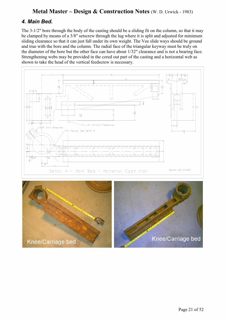
4. Main Bed.
The 3-1/2" bore through the body of the casting should be a sliding fit on the column, so that it may
be clamped by means of a 3/8" setscrew through the lug where it is split and adjusted for minimum
sliding clearance so that it can just fall under its own weight. The Vee slide ways should be ground
and true with the bore and the column. The radial face of the triangular keyway must be truly on
the diameter of the bore but the other face can have about 1/32" clearance and is not a bearing face.
Strengthening webs may be provided in the cored out part of the casting and a horizontal web as
shown to take the head of the vertical feedscrew is necessary.
Metal Master – Design & Construction Notes (W. D. Urwick - 1983)
Page 22 of 52
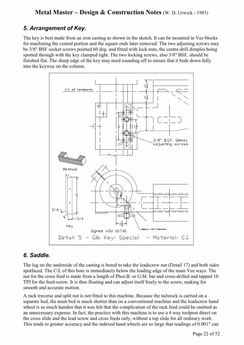
5. Arrangement of Key.
The key is best made from an iron casting as shown in the sketch. It can be mounted in Vee blocks
for machining the central portion and the square ends later removed. The two adjusting screws may
be 3/8" BSF socket screws pointed 60 deg. and fitted with lock nuts, the centre-drill dimples being
spotted through with the key clamped tight. The two locking screws, also 3/8" BSF, should be
finished flat. The sharp edge of the key may need rounding off to ensure that it beds down fully
into the keyway on the column.
6. Saddle.
The lug on the underside of the casting is bored to take the leadscrew nut (Detail 17) and both sides
spotfaced. The C/L of this bore is immediately below the leading edge of the main Vee ways. The
nut for the cross feed is made from a length of Phos.B. or G.M. bar and cross-drilled and tapped 10
TPI for the feed-screw. It is thus floating and can adjust itself freely to the screw, making for
smooth and accurate motion.
A rack traverse and split nut is not fitted to this machine. Because the tailstock is carried on a
separate bed, the main bed is much shorter than on a conventional machine and the leadscrew hand
wheel is so much handier that it was felt that the complication of the rack feed could be omitted as
an unnecessary expense. In fact, the practice with this machine is to use a 4 way toolpost direct on
the cross slide and the lead screw and cross feeds only, without a top slide for all ordinary work.
This tends to greater accuracy and the indexed hand wheels are so large that readings of 0.001" can

Metal Master – Design & Construction Notes (W. D. Urwick - 1983)
Page 23 of 52
be read easily from a standing position in front of the machine.
A substantial gib strip 3/16" thick holds the saddle to the main bed and is located and adjusted by
means of two pointed grub screws and lock nuts, with a third flat ended screw for locking the
saddle to the bed ways, when required.

Metal Master – Design & Construction Notes (W. D. Urwick - 1983)
Page 24 of 52
7. Cross-slide.
In view of the milling capabilities of this machine, a large boring table or cross-slide was desirable
and this is 10" x 4-1/2" with a travel of about 7-1/2". The five Tee slots allow the machine vice to
be placed in any position on the table and for other substantial pieces of equipment such as a
dividing head to be mounted. Since the tailstock can be passed right over the boring table, there is
no problem of overhang of the barrel and the width of the table could be increased to 5" or more
with occasional advantage.
8. Auxiliary Tee Bed.
Since the accuracy of the machine is dependent on the truth of this bed it should be ground on the
machined surfaces of the Vee slides, which are angled at 45 deg.
When long slender work is turned between centres there will be a tendency towards chatter from
the elasticity of the cast iron. This can be considerably lessened by means of a tie rod about 3/8"
dia. fitted so as to link the ends of the two beds. An even more rigid clamp can easily be made up to
tie the tailstock barrel direct to a plate across the surface of the main bed. If the two are connected
by means of a dog-leg link, the vertical feed can still be available, before final tightening of the
bolts, for setting either work or tool centre height.

Metal Master – Design & Construction Notes (W. D. Urwick - 1983)
Page 25 of 52
9. Arrangement of Brackets for Tee Bed.
As will be seen, the auxiliary Tee bed is held up against the ground surfaces of the two straps by
3/8" BSF Hex headed setscrews pressing upwards through the centre of each bracket. This takes
care of the alignment of the Tee bed automatically in the vertical plane. Four socket grub screws
5/16" BSF project through the Tee bed at 45 deg. to seat on the sides of the Vee brackets. A
clearance gap of about 1/8" allows the bed to be positioned in the horizontal plane for accurate
alignment of the tailstock centre, in accordance with setting up procedures.
9a. Straps - 2 off.
The top surfaces of the strengthening ribs may be surfaced to provide a seating for the castings on
the grinding machine. Also see illustration associated with Detail 34a.

Metal Master – Design & Construction Notes (W. D. Urwick - 1983)
Page 26 of 52
10. Spindle.
Material should be good quality steel such as EN 24 and be given a good finish, preferably ground.
The spindle runs in G.M. shells 1-3/8" OD x 1-1/16" ID and 1-3/16" ID respectively. Oil grooves
can be provided. It has been found that occasional lubrication through ordinary oiling caps is all
that is necessary and wear has been negligible over a period of 25 years. Thrust is taken by a large
ball race in the mandrel nose bearing and a fibre washer and fine-threaded collar on the spindle at
the back end of the bearing shell allow for close adjustment.
The spindle is bored 3/4" plus, running into a No. 3 Morse taper, so that large stock material can be
passed through and useful sized collets employed. A reduction sleeve to No. 1 Morse taper takes
normal centres, drill chucks, etc.
Both bearing housings and shells are split 3/32" and fitted with fibre packing pieces, adjusted for
running fit and clamped with 5/16" BSF socket cap screws.
The flywheel pulley is keyed to the spindle with a key 3/16" x 1/8" x 1". A 5/16" BSF socket
grubscrew secures and seats on the key through the bottom of the smallest pulley.
The function of the sliding sleeve and pinion is described under screwcutting and Detail 21.
11. Changewheel Carrier Arm.
There is nothing calling for special comment with this component. The slots should be milled out
to 1/4" to suit the flats on the changewheel studs. The central slot is opened up to 5/16" at one end,
to accept the attachment of the link arm when using the pulley for dividing purposes.

Metal Master – Design & Construction Notes (W. D. Urwick - 1983)
Page 27 of 52
12. Leadscrew.
The leadscrew is 5/8" in diameter x 8 TPI square thread L.H. to suit the special screwcutting
system and the 24 tooth pinion on the spindle sleeve. The leadscrew on this machine is very much
in use but it is so easily removed, together with its nut, that a spare pair could be kept for special
jobs, where great accuracy was required. However, the long solid nut stands up well and I have not
found the necessity for such a spare set.
13. Crosslide Feedscrew and Nut.
The feedscrew is threaded 10 TPI x ½" square thread R.H. and operates in a self aligning Phos.B.
or G.M. nut. This nut is made from a piece of 1" diameter material, cross-bored and threaded. It is a
close working fit in a suitable vertical hole bored through the saddle casting and can therefore
position itself in two directions to align with the placing of the thrust bearing. The screw is thus
freely supported, lending itself to smooth and accurate duty.
14. Headstock Pulley Flywheel.
The design and operation of this pulley was adopted without modification From the Exe 3-1/2"
lathe. It has proved an unqualified success and is a breakaway from traditional practice. It has the
following merits:
a) Its heavy weight (12 lbs.) serves to give momentum to anything held in the chuck and helps
to drive the work past the tool or vice-versa and to eliminate chatter, particularly in parting-

Metal Master – Design & Construction Notes (W. D. Urwick - 1983)
Page 28 of 52
off operations.
b) It serves as a Dividing Head, having 60 holes drilled in its outer rim, with a means of
further subdivision to 360 deg.
c) It dispenses with the need for back-gear and is quiet. If a geared motor is used as the power
unit, a suitable range of speeds can be provided with a single Vee belt drive.
d) It is invaluable for turning the chuck for screwcutting by hand, particularly for short threads up to a shoulder and for the use of taps and dies in a tailstock holder. The rack feed to the
tailstock is also an advantage in this kind of work.
Metal Master – Design & Construction Notes (W. D. Urwick - 1983)
Page 29 of 52
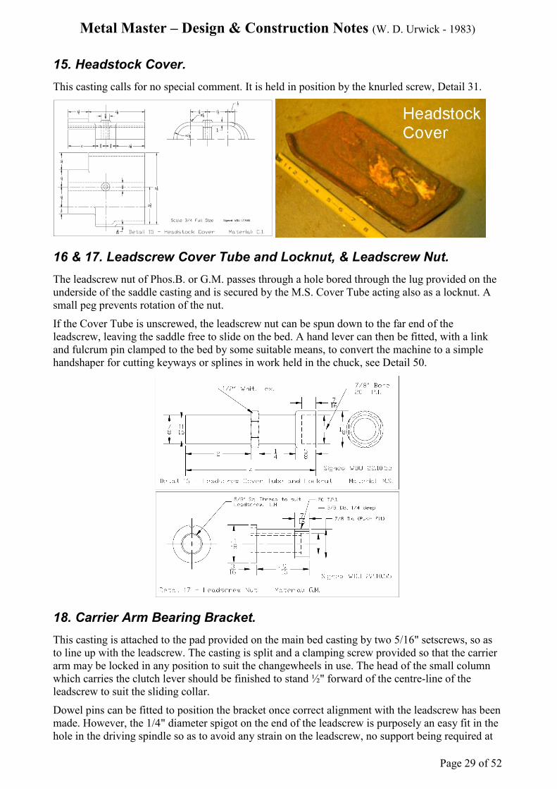
15. Headstock Cover.
This casting calls for no special comment. It is held in position by the knurled screw, Detail 31.
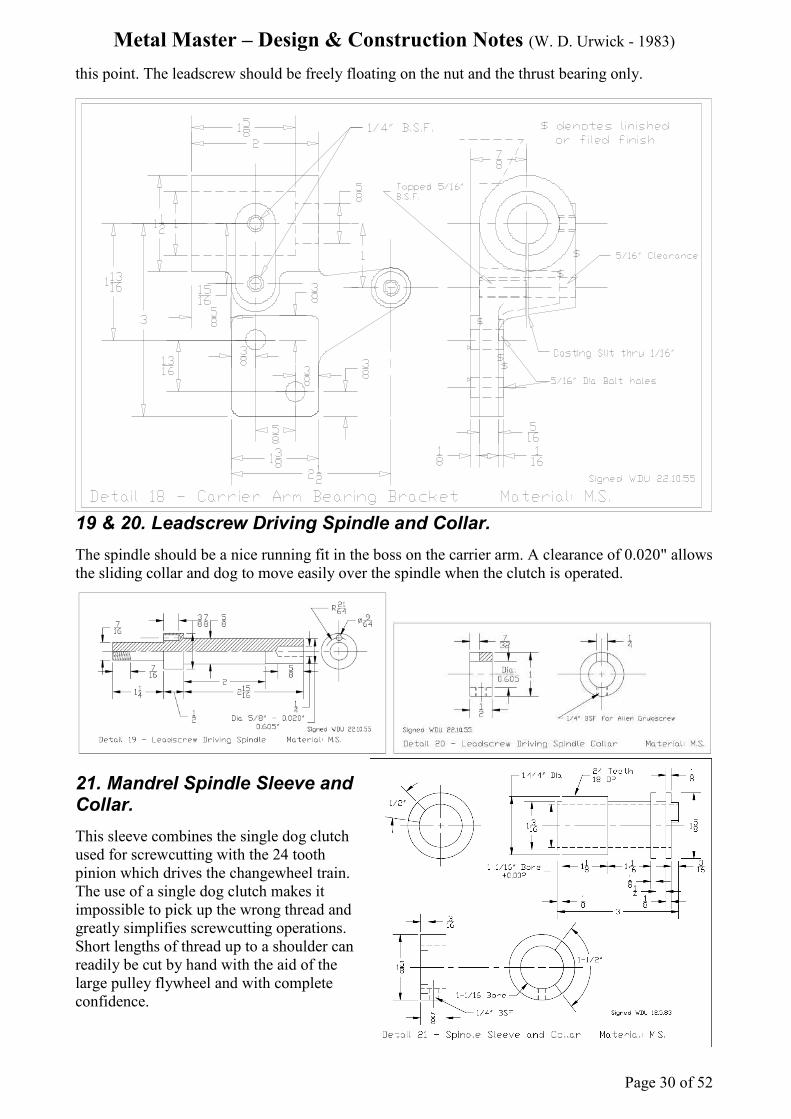
16 & 17. Leadscrew Cover Tube and Locknut, & Leadscrew Nut.
The leadscrew nut of Phos.B. or G.M. passes through a hole bored through the lug provided on the
underside of the saddle casting and is secured by the M.S. Cover Tube acting also as a locknut. A
small peg prevents rotation of the nut.
If the Cover Tube is unscrewed, the leadscrew nut can be spun down to the far end of the
leadscrew, leaving the saddle free to slide on the bed. A hand lever can then be fitted, with a link
and fulcrum pin clamped to the bed by some suitable means, to convert the machine to a simple
handshaper for cutting keyways or splines in work held in the chuck, see Detail 50.
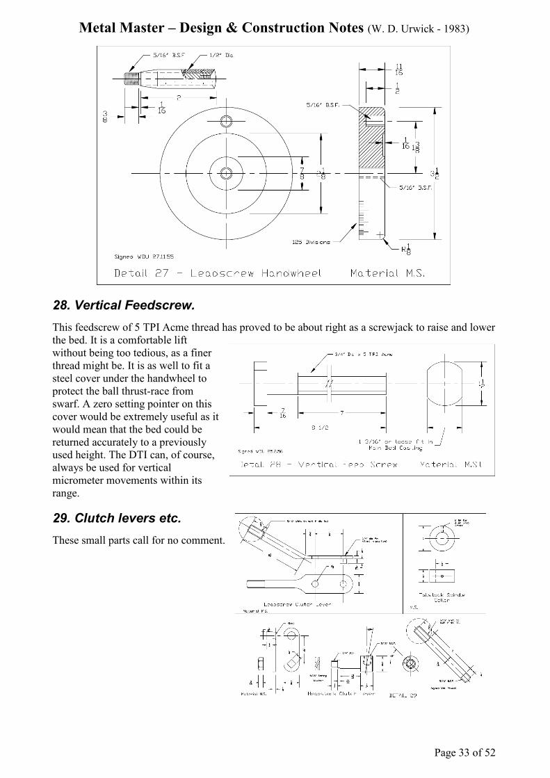
18. Carrier Arm Bearing Bracket.
This casting is attached to the pad provided on the main bed casting by two 5/16" setscrews, so as
to line up with the leadscrew. The casting is split and a clamping screw provided so that the carrier
arm may be locked in any position to suit the changewheels in use. The head of the small column
which carries the clutch lever should be finished to stand ½" forward of the centre-line of the
leadscrew to suit the sliding collar.
Dowel pins can be fitted to position the bracket once correct alignment with the leadscrew has been
made. However, the 1/4" diameter spigot on the end of the leadscrew is purposely an easy fit in the
hole in the driving spindle so as to avoid any strain on the leadscrew, no support being required at
Metal Master – Design & Construction Notes (W. D. Urwick - 1983)
Page 30 of 52
this point. The leadscrew should be freely floating on the nut and the thrust bearing only.
19 & 20. Leadscrew Driving Spindle and Collar.
The spindle should be a nice running fit in the boss on the carrier arm. A clearance of 0.020" allows
the sliding collar and dog to move easily over the spindle when the clutch is operated.
21. Mandrel Spindle Sleeve and Collar.
This sleeve combines the single dog clutch
used for screwcutting with the 24 tooth
pinion which drives the changewheel train.
The use of a single dog clutch makes it
impossible to pick up the wrong thread and
greatly simplifies screwcutting operations.
Short lengths of thread up to a shoulder can
readily be cut by hand with the aid of the
large pulley flywheel and with complete
confidence.

Metal Master – Design & Construction Notes (W. D. Urwick - 1983)
Page 31 of 52
22. Changewheels.
This system of gears, where the number of teeth are in multiples of the number 3 instead of the
usual 5, provide a very comprehensive range of screwthreads using simple trains only. The formula
is very simple: - Number of driven teeth / Number of driving teeth = 3 x TPI.
A working chart for the changewheel trains is given in the Table on page 45 and this has proved to
be adequate for everyday model making purposes.
A single 38 tooth wheel is added to the range to enable 19 TPI to be cut and also because this
wheel gives a useful selection of metric threads to be cut with tolerable accuracy. An additional
changewheel of 50 teeth would be required if it is necessary to cut a 25 or 50 TPI thread.
An advantage of the system is that the largest wheel employed is only 72 teeth, keeping the whole
train exceptionally compact.
23. Cross-slide Feedscrew Handwheel.
The large and heavy handwheel is helpful
in giving a smooth and steady feed. The
space between the indexing marks
representing 0.001" is so large on a 3"
diameter ring that they can be comfortably
read with accuracy from a standing position
in front of the machine. It would be a
simple matter to fit this handwheel with a
zero setting index ring and could be a
useful refinement.
24. Assembly and Details of Dog Clutch.
The clutch collar is keyed to the end of the leadscrew and picks up the drive from the changewheels

Metal Master – Design & Construction Notes (W. D. Urwick - 1983)
Page 32 of 52
for autofeed to the saddle. It is left engaged during screwcutting operations.
25. Cross-slide Feedscrew Bracket.
This small iron casting supports the feedscrew and serves also as a thrust bearing. It should
therefore be accurately spotfaced at both ends of the bore.
26. Changewheel Studs.
Three of these studs are normally in
use, the fourth only being required
for an extra idler when cutting L.H.
threads.
27. Leadscrew Handwheel.
As with the crossfeed handwheel,
this handwheel is of large diameter,
3-1/2", and is heavy to aid a smooth
action. A small index marker with
Vernier scale can be fitted and is
occasionally useful but otherwise a
pointer made from sheet metal will suffice.
Metal Master – Design & Construction Notes (W. D. Urwick - 1983)
Page 33 of 52
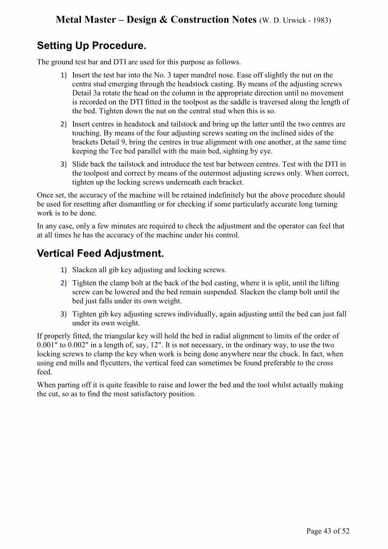
28. Vertical Feedscrew.
This feedscrew of 5 TPI Acme thread has proved to be about right as a screwjack to raise and lower
the bed. It is a comfortable lift
without being too tedious, as a finer
thread might be. It is as well to fit a
steel cover under the handwheel to
protect the ball thrust-race from
swarf. A zero setting pointer on this
cover would be extremely useful as it
would mean that the bed could be
returned accurately to a previously
used height. The DTI can, of course,
always be used for vertical
micrometer movements within its
range.
29. Clutch levers etc.
These small parts call for no comment.

Metal Master – Design & Construction Notes (W. D. Urwick - 1983)
Page 34 of 52
30. Vertical Feed Handwheel.
It may well be possible to find this item or one
very like it as a stock pattern in a foundry. The
dimensions are not critical.
31. Various small Screws.
As the tailstock barrel locking screw is in
continuous use, it is best provided with a small
G.M. pad or pin to seat on the face of the
triangular gib key. The key will hold the barrel
very firmly indeed, owing to its wedge action in
the keyway.
32. Various Tailstock and other items.
The headstock holding nut should have an accurately machined seating face, since it is tightened
down in collaboration with the two adjusting screws for aligning the head and will then need no
washer.
The barrel rack feed is 8 teeth per inch, so that one revolution of the tailstock indexing dial
represents 3" of travel and it may be given scale divisions accordingly. The central locking screw
and pin provide a simple means for zero setting of the dial. For details of the 24 tooth pinion see
drawing No. 45.

Metal Master – Design & Construction Notes (W. D. Urwick - 1983)
Page 35 of 52
33. Faceplate.
With the vertical feed available, a faceplate is an almost unnecessary accessory. Work can be set up
on the boring table so much more easily and accurately, with the aid of the DTI, and machined by
means of tools in the chuck or on the boring head, that a faceplate will be very rarely used.

Metal Master – Design & Construction Notes (W. D. Urwick - 1983)
Page 36 of 52
34. Tailstock.
This casting needs to be machined with particular attention to the vertical dimension of 2.25"
between the top sliding surface of the auxiliary Tee bed and the centre line of the barrel. This
dimension should be to limits of +/- 0.00001", but adjustment is possible, see 34a. On the original
prototype machine the tailstock barrel was bored in the machine itself, so as to remove any chance
of error. No doubt if the machine were to be put into production a suitable jig could be set up to
ensure that the castings were interchangeable.
The horizontal distance of 5" from the barrel centre line to the midpoint of the Tee bed is not so
critical because allowance for adjustment is made in the brackets supporting the auxiliary Tee bed.
The barrel housing is drilled partially through from the back to provide a runout for the tool when
cutting the triangular keyway for the key. Two setscrews and locknuts can be adjusted to remove
all shake and the barrel can be locked very securely with the central locking screw tightened down
onto the key.
A valuable feature of this machine is that the tailstock can be passed right over the saddle and the
boring table can therefore be as wide as may be found useful, with no problem of overhang of the
tailstock barrel.
A simple sheet metal tool tray screwed to the flat top surface of the tailstock casting is very
convenient for holding turning tools and spanners.

Metal Master – Design & Construction Notes (W. D. Urwick - 1983)
Page 37 of 52
34a. Alignment of centres in vertical plane.
Any small error in the machining of the tailstock
casting to the critical dimension of 2.25"
between the sliding surface and the bore of the
barrel will show up as a misalignment of the
centres in the vertical plane. This can best be
corrected by re-grinding the faces of the two
strips (Detail 9a), with suitable steps between
the central portion that rests on the top surface
of the Tee bed and the end portions resting on
the brackets. See illustration.
35 & 36. Four Way Toolpost.
This toolpost is normally used on this machine for all general work, the topslide only being
occasionally used for cutting short tapers or for feeding in the screwcutting tool at the thread angle.
No packing of tools to centre height is necessary with the vertical feed always to hand and the short
main bed and large feedscrew dials are more convenient to use than a topslide.
The tapered locking pin need only be sufficiently tightened down to prevent the toolpost moving
about because the whole unit will be held down firmly when the main clamping arm is pulled down
hard.
37. Link Arm for 60 hole Division Plate.
The link arm works on a fulcrum pin attached to the Carrier Arm and can pick up any of the 60
holes in the rim of the flywheel pulley and so lock the mandrel. The subdivision device enables
pieces of work in the chuck or on the faceplate to be divided into degrees of angle with
considerable accuracy.
Movement of the Carrier Arm on its spindle allows a small amount of movement to a scribing tool
picking up an initial zero mark on the work. The register pin on the link arm should be tapered so
as to make a close spring fit in the 7/32" hole in the rim of the flywheel pulley.

Metal Master – Design & Construction Notes (W. D. Urwick - 1983)
Page 38 of 52
38. Four Small Items.
The leadscrew bearing can be made from 3/4" square Phos.B. or G.M. stock bar. The M.S. thrust
collar bears on one side face of the bearing and the handwheel nut on the other, locking with the
threaded hole in the handwheel itself and with a final locknut on the end of the thread. These parts
can be adjusted to provide working clearance for the leadscrew and smooth action. A single 5/16"
bolt passes right through the main bed casting to hold the bearing against the pad provided.
The tailstock locking screw can be given a plain crosspin for tightening purposes or it is better to fit
a ball headed lever about 4-1/2" long which can project above the tool tray for easy access. The
most convenient position for this lever when locked can be determined by adjustment of the length
of the boss or G.M. pin. A small fixed pin in the back of the tailstock casting can limit the
movement of the lever when in the unlocked position. If the lever is screwed into the head of the
locking screw at an angle of about 55 deg. it will comfortably clear the back of the casting with
freedom to swing.
39. Topslide Base.
A similar arrangement to that of the cross-slide is used for the nut and the feedscrew, the nut being
made by crossdrilling and threading a short length of 3/4" diameter Phos.B. or G.M. rod. This
cylindrical piece of metal floats in a vertical hole bored in the casting and so can find its own
alignment with the feedscrew and bearing. This results in a smooth and accurate action.
The whole topslide is clamped to the boring table by means of a taper pointed socket cap-screw,
which enters a recess of similar taper 60 deg. in a special slot bolt. The recess is drilled 1/16" below
the axis of the cap-screw, so that as the latter is tightened it draws up the slot bolt and clamps the
topslide. The topslide can therefore be fixed in any slot and at any required angle. A protractor can
be laid against the machined face of the base casting for setting to any desired angle of taper.

Metal Master – Design & Construction Notes (W. D. Urwick - 1983)
Page 39 of 52
40. Topslide.
A solid section gib strip is used for the slide in view of the amount of overhang and the possibility
of spring with a thin strip. If two locating pins are provided, the adjusting screws can be flat ended
to seat on the vertical back face of the gib key.
A substantial 3/8" post can be fitted with any sort of tool clamp desired. A small plate with a light
spring beneath it and an adjustment screw for height has served very well.

Metal Master – Design & Construction Notes (W. D. Urwick - 1983)
Page 40 of 52
41. Topslide Feedscrew Bracket and Handwheel.
The feedscrew is threaded 3/8" BSF so as to give 20 turns of the handwheel per inch of travel. The
handwheel can then have 50 divisions each representing 0.001" and these on a 1-1/2" dial will be
about 3/32" apart and convenient to read.
The feedscrew bracket can be a small iron casting or milled from a piece of mild steel.
42 & 43. Tool Tray & Suds Tray.
These can be fabricated from sheet metal and are best rustproofed and stove enameled.

Metal Master – Design & Construction Notes (W. D. Urwick - 1983)
Page 41 of 52
44. Ground Test Bar.
This test bar is best made
from 1" ground stainless
steel and is an essential
accessory. It must have
accurate centres and one
end should be No. 3 Morse
taper to fit the mandrel
nose. It should be kept
available at any time for
use in lining up the
machine or as a final check
when the auxiliary Tee bed
has been removed to allow
for a workpiece greater
than 8" diameter or when
the main triangular key has
been removed for taper
turning.
45. Tailstock Barrel.
The barrel is bored to pass
3/8" stock material and
the nose is made to suit
No. 1 Morse taper centres,
drillchuck, end mills, etc.
The keyway can be cut
with a 45 deg. side and
face cutter, care being
taken to ensure that the
radial face is truly on the
diameter of the barrel.
The rack feed is 8 TPI
which, with a 24 tooth
pinion, gives 3" of travel
of the barrel for one
revolution of the pinion.
The dial can therefore be
indexed in inches and the
usual subdivisions.
46 & 47. Dial Test Indicator and Base.
A good DTI is a necessary accessory with this machine. It is required for use in conjunction with
the ground test bar for setting up to the zero-taper condition. If an attachment is made to slide on
the auxiliary Tee bed and it carries the DTI on a universal arm, it can be kept in this position and
will be immediately available to check every kind of work, whether round or flat, both in the chuck
and on the cross-slide boring table. The vertical feed can also be indexed by means of this
attachment and, in fact, the top face of the auxiliary bed becomes a kind of fixed datum line in
space, to which all measurements may be referred. It is well worth making this quick fitting device

Metal Master – Design & Construction Notes (W. D. Urwick - 1983)
Page 42 of 52
and the time taken in its construction will be rapidly recovered by its use.
48. Machine Vice.
As there is no lack of room in the vertical direction, the vice can have good deep jaws with
advantage. It will be much in use and should be capable of being bolted to the boring table at any
angle. This can be achieved very well by fitting the vice with a circular slotted baseplate as shown
in the drawing.
Metal Master – Design & Construction Notes (W. D. Urwick - 1983)
Page 43 of 52
Setting Up Procedure.
The ground test bar and DTI are used for this purpose as follows.
1) Insert the test bar into the No. 3 taper mandrel nose. Ease off slightly the nut on the
centra stud emerging through the headstock casting. By means of the adjusting screws
Detail 3a rotate the head on the column in the appropriate direction until no movement
is recorded on the DTI fitted in the toolpost as the saddle is traversed along the length of
the bed. Tighten down the nut on the central stud when this is so.
2) Insert centres in headstock and tailstock and bring up the latter until the two centres are touching. By means of the four adjusting screws seating on the inclined sides of the
brackets Detail 9, bring the centres in true alignment with one another, at the same time
keeping the Tee bed parallel with the main bed, sighting by eye.
3) Slide back the tailstock and introduce the test bar between centres. Test with the DTI in the toolpost and correct by means of the outermost adjusting screws only. When correct,
tighten up the locking screws underneath each bracket.
Once set, the accuracy of the machine will be retained indefinitely but the above procedure should
be used for resetting after dismantling or for checking if some particularly accurate long turning
work is to be done.
In any case, only a few minutes are required to check the adjustment and the operator can feel that
at all times he has the accuracy of the machine under his control.
Vertical Feed Adjustment.
1) Slacken all gib key adjusting and locking screws.
2) Tighten the clamp bolt at the back of the bed casting, where it is split, until the lifting
screw can be lowered and the bed remain suspended. Slacken the clamp bolt until the
bed just falls under its own weight.
3) Tighten gib key adjusting screws individually, again adjusting until the bed can just fall under its own weight.
If properly fitted, the triangular key will hold the bed in radial alignment to limits of the order of
0.001" to 0.002" in a length of, say, 12". It is not necessary, in the ordinary way, to use the two
locking screws to clamp the key when work is being done anywhere near the chuck. In fact, when
using end mills and flycutters, the vertical feed can sometimes be found preferable to the cross
feed.
When parting off it is quite feasible to raise and lower the bed and the tool whilst actually making
the cut, so as to find the most satisfactory position.

Metal Master – Design & Construction Notes (W. D. Urwick - 1983)
Page 44 of 52
The following drawings exist without notes from David Urwick.
49. Vernier Index for Leadscrew Handwheel.
50. Racking Lever Attachment.

Metal Master – Design & Construction Notes (W. D. Urwick - 1983)
Page 45 of 52
51. Ball Turning Tool.
52. Stand.

Metal Master – Design & Construction Notes (W. D. Urwick - 1983)
Page 46 of 52
53. Clamping Jig for Small Parts.
54. Tailstock Dieholder.
Metal Master – Design & Construction Notes (W. D. Urwick - 1983)
Page 47 of 52
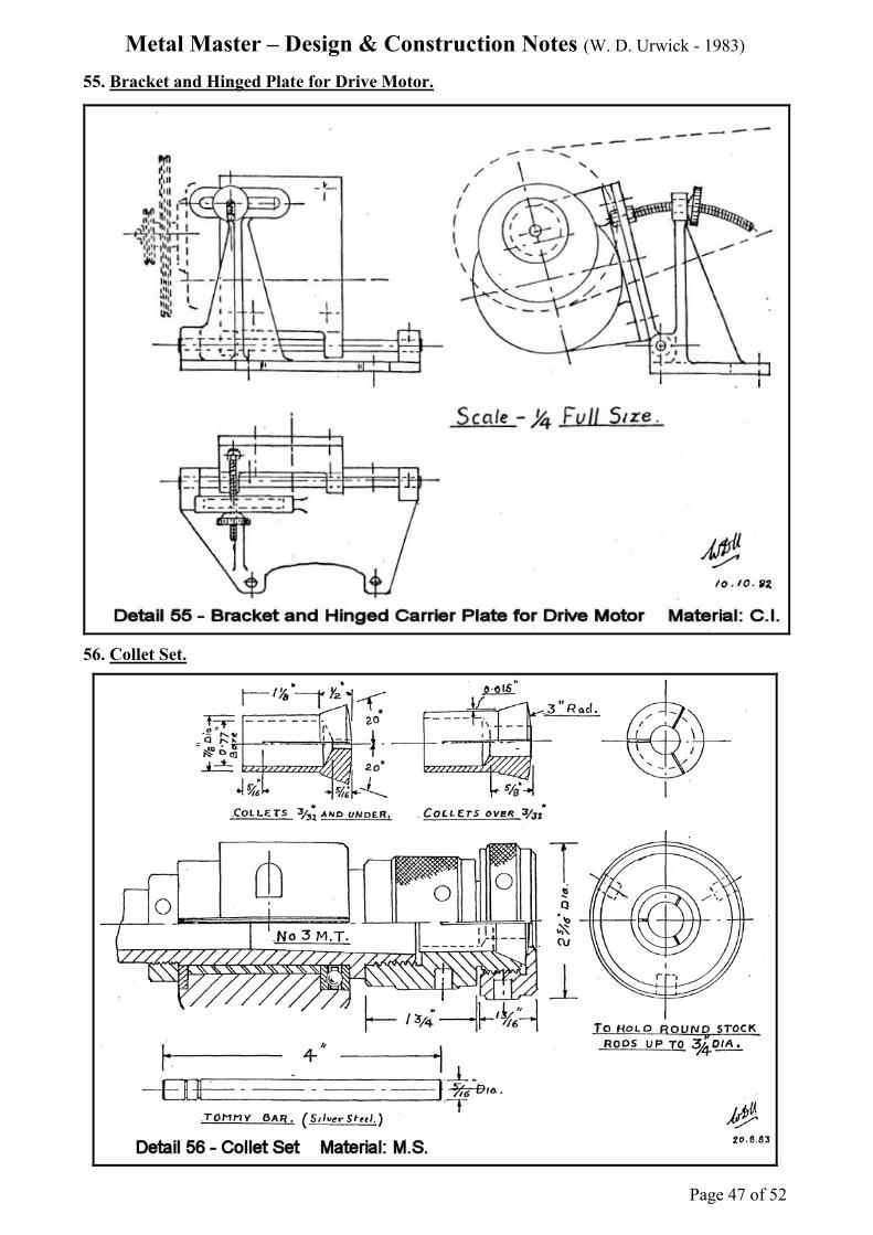
55. Bracket and Hinged Plate for Drive Motor.
56. Collet Set.

Metal Master – Design & Construction Notes (W. D. Urwick - 1983)
Page 48 of 52
The following drawings are listed in the Schedule of Drawings but are not included with the known
set of drawings.
Boring Head.
1. Body.
2. Slide.
3. Feedscrew.
4. Nut.
5. Thrust Block.
6. Index Locknut, Thrust Locknut, and Thrust Ring.
7. Handwheel.
8. Spider.
9. Arrangement of Trip Pin.
10. Facing Tool Holder.
________________________________________________________________________
Additionally, a Dividing Head is mentioned in some of the literature on the MetalMaster and is
shown in at least one photograph of David Urwick's personal machine. No mention of it is made in
Urwick's notes nor are any drawings included with the known set of drawings.

Metal Master – Design & Construction Notes (W. D. Urwick - 1983)
Page 49 of 52
Change Wheel Chart - Metal Master TPI x 3 = A x C
B
Threads per
Inch A
Wheel on
Leadscrew
B Driver
C Driven
Right Hand
Idler
Left Hand
Idler
4 24 36 18 1 2
5 30 36 18 1 2
6 18 - 2 3
7 21 - 2 3
8 24 - 2 3
9 27 - 2 3
10 30 - 2 3
11 33 - 2 3
12 36 - 2 3
13 39 - 2 3
14 54 27 21 1 2
15 36 24 30 1 2
16 54 27 24 1 2
18 54 - - 2 3
19 54 24 21 1 2
20 54 27 30 1 2
22 54 27 33 1 2
24 54 27 36 1 2
26 54 27 39 1 2
28 72 18 21 1 2
30 72 24 30 1 2
32 72 18 24 1 2
36 72 18 27 1 2
40 72 18 30 1 2
44 72 18 33 1 2
48 72 18 36 1 2
52 72 18 39 1 2
56 72 18-27 21-54 1 2
60 72 18-24 30-36 0 1
64 72 18-27 24-54 0 1
Coarse Feed 72 18-21 39-54 0 1
Fine Feed 72 18-18 54-60 0 1
Pitch (mm) Metric Threads
0.50 72 18 38 1 2
0.55 72 18-33 30-38 0 1
0.70 54 21-27 38-30 0 1
0.75 72 27 38 1 2
1.00 72 36 38 1 2
1.50 38 27 36 1 2
1.75 38 21 24 1 2
2.00 38 - - 2 2
2.25 38 27 24 1 2
2.50 38 30 24 1 2
2.75 38 33 24 1 2
3.00 24 36 38 1 2
3.25 24 39 38 1 2
4.00 18 36 38 1 2

The Designer Writes With thanks to Mike Collins - who made available the material for these pages.
By W.D.URWICK. C.Eng., M.I.Mech.E. (First Published in the SIMEC Newsletter in September 1973)
Page 50 of 52
Some twenty years ago I designed and built for my
workshop the small general-purpose tool here described
and it has proved such an unqualified success that I think
the ideas behind it must interest readers of your
Newsletter. I felt that for too long we have been
constrained by the principles of Maudsley and that the
model engineer particularly, requires a small machine
with the greatest possible scope and capacity, which the
orthodox bench lathe in miniature is far from providing.
A centre lathe makes a poor milling machine for lack of a
vertical feed to the cross-slide or work table. A milling
machine makes a poor lathe because of the difficulty of
maintaining accuracy for turning between centres with a
rise and fall cantilevered bed. A horizontal boring
machine is a fine maid-of-all-work but is not much use as
a lathe and is not, in any case, available in a small
workshop size. All these machines, nevertheless, have a
headstock, a tailstock and a work table or cross-slide and,
after a great deal of thought, I managed to rearrange these
components to give me the flexibility I sought.
The headstock of my machine is mounted on top of a
massive column, with a cantilevered bed carried on the
column beneath it and raised and lowered by a jacking
screw at its point of balance. An auxiliary Vee bed carries
the tailstock and is mounted in brackets behind the
headstock. The top surfaces of these brackets are ground
true with the mandrel and the auxiliary bed is held by
screws forcing it upwards against straps seated on the
ground surfaces of the brackets.
Thus, the working surfaces of the two beds, the headstock
mandrel and the tailstock barrel are all strictly parallel in
the vertical plane. However, when looking down on the
machine from above, alignment of all these parts can be
achieved by radial adjustment, with the column as centre,
and this adjustment is under the control of the operator. It
will be clear that, for the success of this arrangement, one
component, the cantilevered bed, must retain its radial
relationship with the column with extreme accuracy and
this I achieved with a special triangular gib key, which I
invented and patented at the time. A sketch of part of the
original Patent Drawing is shown here, though the patent
itself has, of course, expired.
The startling performance of this key in maintaining
accuracy has to be seen to be believed. Its very simplicity
is deceptive. When raised or lowered on the jacking screw
and re-clamped, the outer end of the bed can be relied
upon not to deviate by more than .001" to .002" in radial
alignment. One must appreciate that at this radius the key
is operating at a disadvantage of about 20 to 1! An error
of this order over a length of 18" is probably as good as
one would expect from any orthodox light machine of this
class.
The Triangular Gib Key has three great points in its
favour for this particular application:
1. The alignment of the bed with the mandrel can be
maintained to very close limits indeed, when it is
raised or lowered, on account of the keyway faces
themselves being radial.
2. When locked, the key acts as an extremely rigid
clamp and being of wedge shape, can be adjusted
to a very close sliding fit, like a gib strip, and yet it
clears instantly on release. The sliding clearance at
the key faces can be so small that, with normal
work anywhere near the chuck, it is unnecessary to
apply the locking screw and clamp the bed. The
vertical feed can be used for milling or other
purposes as freely as the cross-slide or leadscrew
feeds.
3. If the key is removed, the whole bed can be swung
radially and locked, for turning work to any desired
taper. In fact, the arrangement can be summed up
by saying that parallel turning is merely a case of
"zero taper."
Adjusting screws are provided for truing up the mandrel,
and the auxiliary bed and tailstock to fine limits and with
the aid of a test bar, this radial lining up of the machine
can be achieved in a matter of minutes.
In considering the general details of this machine many
3.1/2" centre lathes were considered and an attempt was
made to adopt the best features that could be found
amongst them. Of these lathes, undoubtedly the most
original and useful of all was the 3 1/2" Exe machine, on
the market in the 1930's. The headstock arrangements and
screwcutting details of this beautiful little machine were
adopted and no better choice could have been made. The
mandrel carries at its outboard end a 12" driving pulley
weighing about 12 lbs. The power unit used is a Higgs 1/2
h.p. geared motor, the output shaft running at
approximately 300 r.p.m. This shaft carries a 2-step
driving pulley, thus giving eight mandrel speeds varying
from 45 to 900 r.p.m., using a single Vee belt which can
be freely thrown on and off the pulleys. However the
main function of the heavy pulley on the mandrel is to
give "flywheel effect" and provide momentum between
workpiece and tool as the cutting operation takes place.
With a light machine this momentum makes all the
difference in eliminating chatter and I can turn without
difficulty 8" dia. C.I. traction engine wheels or a 12" dia.
aluminium pulley. The auxiliary bed is removed to
accommodate large diameters above 8". I was recently
able to put a taper bore in the boss of a 10" dia. marine
propeller. It is very useful to be able to swing such an
article, the operation itself being well within the capacity
of the machine. For this job the main bed was rotated on
the column to the correct taper, after the key had been

The Designer Writes With thanks to Mike Collins - who made available the material for these pages.
By W.D.URWICK. C.Eng., M.I.Mech.E. (First Published in the SIMEC Newsletter in September 1973)
Page 51 of 52
removed and, at this slight angle, automatic feed could
still be used.
The screwcutting arrangement too is most ingenious and
possibly unfamiliar. A sleeve on the mandrel carries a 24-
tooth wheel, which drives the changewheel train, and also
incorporates a single-dog clutch by which it takes its drive
from the mandrel. In screwcutting, this clutch is used to
engage the changewheel train, with the result that it is
impossible to pick up the wrong thread!
In addition to this, the number of teeth on the
changewheels are all multiples of the number 3 instead of
the usual 5. These numbers 18, 21, 24, 27, etc., break
down into simple fractions far better than the usual ones
and the formula with an 8 T.P.I. lead-screw is simply:
No. of driven teeth = 3 x T.P.I.
No. of driving teeth
Metric threads can also be cut with the addition of one 38-
tooth wheel. The number 3 and its multiples are so
convenient mathematically that it is difficult to
understand why the awkward system using multiples of 5
has persisted for so long.
A boring head with cross feed, operated by star wheel and
trip pin, was designed to fit the mandrel nose and with
this in action, the machine can, with justification, be
described as a miniature horizontal borer. The boring
head is in use almost as much as the chuck, for facing,
boring and even internal screwcutting awkward shaped
castings.
I should feel completely lost without my vertical feed.
There must be a saving in time alone of the order of 20%
in never having to pack tools and boring bars. When
parting off, I find that I can raise or lower the tool to the
best cutting height whilst actually making the cut.
After machining many hundreds of parts for models and
other things, I feel that I have still not explored all the
possibilities opened up by the facility of being able to
feed the worktable freely in three dimensions in front of
the mandrel nose.
W. D. Urwick
Malta

The Metalmaster - a modern review:
At some point in the early 1970s David became interested in model Stirling engines and it was as a result of an article
that he wrote on his moving regenerator type in Model Engineer that I first wrote to him. A long correspondence and
friendship followed and when David returned to England from his retirement home in Malta I was able to visit him at
his new home in Somerset. Naturally we gravitated to his newly-built workshop where I saw not only his collection of
Stirling engines but also his Metalmaster, a machine that had fascinated me ever since reading about it in the Model
Engineer back in the fifties.
Unfortunately it wasn't working as, during the journey back from Malta, the cross-slide feed-screw nut had been lost.
However, within a couple of days I had made and posted a replacement to him and the next time I visited I was able to
play with the machine.
Sadly, a few years later, poor David became a victim of Parkinson's Disease and, anxious that his machine should go to
an appreciative owner, he offered it to me. A fair price was agreed and I became its proud owner.
Seen here (se image on page one) with the machine are some of the accessories, including the boring head and topslide
mentioned in the brochure, together with the vice designed to fit the cross-slide and a matching dividing head. The
saddle fitted on the parallel auxiliary bed is my own addition and can be slid along by hand before locking in position.
It was originally made to hold a fixed steady but, in addition, proves very useful for holding the lamp, the D.T.I. and
the home-made tool height setter, a device similar to the old 'Unique' indicator, which can be swung out from under the
saddle to sit on the tool tip.
There is little I can add to David's article re the versatility of the machine, it is certainly all that he claimed for it and
can be converted to any of its functions within a couple of minutes. Its accuracy was all that he claimed for it although
now, after nearly fifty years of 'amateur' use, is slightly impaired by wear at the headstock end of the bed. (In
retrospect, David thought that since the tailstock was no obstacle, the saddle could have been made rather longer with
some advantage) I can't really comment on the machine's rigidity since I normally use it for building small model
Stirling engines and handle it like cut glass - nevertheless, recent jobs have included skimming the brake drums of my
wife's Morris Minor and re-machining the base of an Indian cylinder barrel, requiring the full fourteen inch swing to
accommodate the finning around the valve seats. Sumitomo tips are very satisfactory for all these straightforward
turning and boring jobs.
David's geared-motor drive was becoming very noisy and has been replaced with a Sinclair C5 motor with infinitely-
variable speed control since when parting off inch and a quarter steel has become a real pleasure - albeit a slow one!
Finally, I must agree with his remarks regarding the usefulness of the vertical feed - handling a conventional lathe now
feels like working with one hand tied behind my back. And the sheer versatility of the machine has given me a new
hobby - that of finding new jobs for it to do. Mitering picture frames took longer than expected though, due to the need
for spotless cleanliness.
Mick Collins