the mitc3+ shell element and its...
TRANSCRIPT

Computers and Structures 138 (2014) 12–23
Contents lists available at ScienceDirect
Computers and Structures
journal homepage: www.elsevier .com/locate/compstruc
The MITC3+ shell element and its performance
http://dx.doi.org/10.1016/j.compstruc.2014.02.0050045-7949/� 2014 Elsevier Ltd. All rights reserved.
⇑ Corresponding author. Tel.: +82 42 350 1512; fax: +82 42 350 1510.E-mail address: [email protected] (P. S. Lee).
Youngyu Lee a, Phill-Seung Lee a,⇑, Klaus-Jürgen Bathe b
a Division of Ocean Systems Engineering, Korea Advanced Institute of Science and Technology, 291 Daehak-ro, Yuseong-gu, Daejeon 305-701, Republic of Koreab Department of Mechanical Engineering, Massachusetts Institute of Technology, Cambridge, MA 02139, USA
a r t i c l e i n f o
Article history:Received 2 January 2014Accepted 22 February 2014
Keywords:Shell structuresShell finite elements3-Node elementMITC methodConvergence
a b s t r a c t
In this paper, we present an effective new 3-node triangular shell finite element, called the MITC3+ ele-ment. The new shell element is based on the concepts earlier published for the MITC3 shell element (Leeand Bathe, 2004) [1] but is enriched by a cubic bubble function for the rotations. A new assumed trans-verse shear strain field is developed for the element. The shell element passes the three basic tests (theisotropy, patch and zero energy mode tests) and shows excellent convergence behavior in basic andencompassing convergence tests.
� 2014 Elsevier Ltd. All rights reserved.
1. Introduction
During the last decades, the finite element method has beenwidely used for the analysis of shell structures. However, althougha great effort has been expended to develop an effective 3-nodeshell finite element, no element is currently available that has beenshown to be reliable and effective in the analysis of general shellstructures [1–11]. Such element should show isotropic behaviorand pass the consistency, ellipticity and inf–sup conditions andhence be optimal in convergence regardless of the shell geometry,thickness of the shell, boundary conditions and applied loading[2,3]. The highly sensitive and complex behavior of shell structureshas made it extremely difficult to establish such an element [3,12–16].
Shell structures can exhibit membrane dominated, bendingdominated and mixed behaviors, with high strain gradients ininternal and boundary layers. An effective finite element formula-tion should be able to represent these behaviors and converge atoptimal rate in an appropriate norm for any shell thickness. If a fi-nite element discretization cannot accurately approximate thepure bending displacement fields of shells, the solution accuracydeteriorates in bending dominated and mixed shell behaviors. Thisphenomenon is called ‘‘locking’’ and can be severe when the shellthickness decreases [2,3,12]. To alleviate the locking behavior,while preserving the properties of consistency and ellipticity, theMITC method has been successfully used to establish quadrilateraland triangular shell elements [1,2,17–21]. However, while the
3-node triangular MITC3 element is useful, the element is not opti-mal in its convergence behaviors [1,11].
An important point is that to generate meshes for a triangularshell element is relatively easy, even for complex shell analyses.In addition, an effective 3-node shell element would be attractivedue to the small bandwidth of the governing global stiffness andmass matrices. So far, 4-node quadrilateral shell elements, andnotably the 4-node MITC4 element, have been dominantly usedin practice due to their superior performance compared totriangular shell elements. However, these quadrilateral elementsdeteriorate in their convergence behaviors when the elementsare geometrically distorted, see e.g. Ref. [22].
In general, 3-node triangular elements for the two-dimensionalanalysis of solids and the analysis of shells suffer from a lack of dis-placement modes [2,9,10]. To overcome this inherent limitation insome elements, a scheme to enrich the displacement field can beeffective [22–25]. In particular, bubble functions have been usedto improve the predictive capability of finite elements for two-and three-dimensional solid and fluid flow analyses, and for plateand shell solutions [2,20,24,26–29]. A cubic bubble function for a3-node triangular element is attractive [24,26] because it providesa higher-order interpolation inside the element while maintainingthe linear interpolation along the element edges, thus providingcompatibility between elements.
In the development of the new triangular 3-node shell element,which we call the MITC3+ shell element, we use a cubic bubblefunction for the interpolation of the rotations to enrich the bendingdisplacements. That is, only 2 internal rotation degrees of freedomare added to the standard 3-node shell element. Hence, the bubblefunction does not affect the mid-surface displacement of the shell

Y. Lee et al. / Computers and Structures 138 (2014) 12–23 13
element, and the corresponding degrees of freedom can be stati-cally condensed out on the element level.
To reduce shear locking in the shell element, a new assumedtransverse shear strain field is designed. The MITC3+ shell elementpasses all basic tests, that is, the isotropy, zero energy mode andpatch tests, and shows an excellent convergence behavior in thesolution of plate and shell benchmark problems, even whenseverely distorted meshes are used.
In the following sections, the formulation of the MITC3+ shellelement is given and the performance of the element is presented.
2. Formulations of the triangular shell finite elements
In this section, we briefly recall the formulation of the MITC3shell element and then present the formulation of the new MITC3+shell element.
2.1. The MITC3 shell finite element
The geometry of a standard 3-node continuum mechanics basedtriangular shell finite element is interpolated using [1,2]
x!ðr; s; tÞ ¼X3
i¼1
hiðr; sÞ x!i þt2
X3
i¼1
aihiðr; sÞV!i
n with
h1 ¼ 1� r � s; h2 ¼ r; h3 ¼ s; ð1Þ
where hi(r, s) is the two-dimensional interpolation function of thestandard isoparametric procedure corresponding to node i, x!i isthe position vector of node i in the global Cartesian coordinate sys-tem, and ai and V
!in denote the shell thickness and the director vec-
tor at the node, see Fig. 1.The corresponding displacement interpolation of the element is
u!ðr; s; tÞ ¼X3
i¼1
hiðr; sÞ u!i þt2
X3
i¼1
aihiðr; sÞ �V!i
2ai þ V!i
1bi
� �; ð2Þ
in which u!i is the nodal displacement vector in the global Cartesiancoordinate system, V
!i1 and V
!i2 are unit vectors orthogonal to V
!in
and to each other, and ai and bi are the rotations of the director vec-tor V!i
n about V!i
1 and V!i
2, respectively, at node i.The linear terms of the displacement-based covariant strain
components are given by
eij ¼12
g!i � u!;j þ g!j � u!;i
� �; ð3Þ
Fig. 1. A standard 3-node triangular continuum mechanics based shell finiteelement.
in which
g!i ¼@ x!
@ri; u!;i ¼
@ u!
@riwith r1 ¼ r; r2 ¼ s; r3 ¼ t: ð4Þ
Since the 3-node triangular shell finite element is flat, thecovariant in-plane strain components are calculated using Eqs.(1)–(3). However, the covariant transverse shear strain field isestablished using the MITC scheme. The transverse shear strainfield of the MITC3 shell element is based on assuming constantcovariant transverse shear strain conditions along the edges
~eMITC3rt ¼ eð1Þrt þ cs; ~eMITC3
st ¼ eð2Þst � cr; ð5Þ
where c ¼ eð3Þrt � eð1Þrt
� �� eð3Þst � eð2Þst
� �and the tying points are shown
in Fig. 2 [1].
2.2. The MITC3+ shell finite element
The geometry interpolation of the MITC3+ shell element, shownin Fig. 3, is given by
x!ðr; s; tÞ ¼X3
i¼1
hiðr; sÞ x!i þt2
X4
i¼1
ai f iðr; sÞV!i
n with
a4 V!4
n ¼13
a1 V!1
n þ a2 V!2
n þ a3 V!3
n
� �; ð6Þ
in which the fi(r, s) are two-dimensional interpolation functionsthat include the cubic bubble function f4 corresponding to the inter-nal node 4
f1¼h1�13
f4; f 2¼h2�13
f4; f 3¼h3�13
f4; f 4¼27rsð1� r� sÞ: ð7Þ
From Eq. (6), we obtain the displacement interpolation [1]
u!ðr; s; tÞ ¼X3
i¼1
hiðr; sÞ u!i þt2
X4
i¼1
ai f iðr; sÞ �V!i
2ai þ V!i
1bi
� �; ð8Þ
in which a4 and b4 are the rotation degrees of freedom at the bubblenode.
The bubble node, with rotation degrees of freedom only, is posi-tioned on the flat surface defined by the three corner nodes of theelement. Only the bending and transverse shear strain fields areenriched by the bubble function, and the geometry of the elementwould remain flat, as for the MITC3 element, if a large deformationanalysis were pursued. Also, static condensation can be carried outon the element level for the rotations a4 and b4.
Fig. 2. Tying positions for the assumed transverse shear strain field of the MITC3shell element. The constant transverse shear strain conditions are imposed along itsedges.

Fig. 3. Geometry of the MITC3+ shell element with an additional bubble node.
(a)
(b)
Fig. 4. In-plane twisting mode of a single shell finite element. (a) Undeformedgeometry. (b) In-plane twisting mode.
Table 1Tying positions for the new assumed transverse shear strain fields for the MITC3i andMITC3+ shell elements. The distance d is defined in Fig. 5(c).
Tying positions r s
Fig. 5(b) (A) 1/6 2/3(B) 2/3 1/6(C) 1/6 1/6
Fig. 5(c) (D) 1/3 + d 1/3 � 2d(E) 1/3 � 2d 1/3 + d(F) 1/3 + d 1/3 + d
14 Y. Lee et al. / Computers and Structures 138 (2014) 12–23
As for the MITC3 shell element, we only use the mixed interpo-lation for the transverse shear strain components, but we must de-sign a new assumed transverse shear strain field because the effectof the bubble function should be included.
To design the new assumed transverse shear strain field, we fo-cus on two considerations. Firstly, the tying points for the covarianttransverse shear strain components should be inside the element,that is, not on the element edges as for the MITC3 element, becausethe bubble function is zero along the element edges. Secondly, thestiffness of the in-plane twisting mode, see Fig. 4, must be reduced[10].
Considering a 3-node triangular shell element (that is, withoutthe node for the bubble), the transverse shear strains occur in twotransverse shearing modes and in an in-plane twisting mode. Thein-plane twisting mode corresponds to twisting of the elementabout the axis normal to the mid-surface at the barycenter,r = s = 1/3, as shown in Fig. 4, with zero transverse shear strainsat that point.
The transverse shear strain field of the MITC3 shell element canbe separated into the constant part corresponding to the transverseshearing modes and the linear part corresponding to the in-planetwisting mode
~eMITC3rt ¼ ~econst:
rt þ ~elinearrt ; ~eMITC3
st ¼ ~econst:st þ ~elinear
st : ð9Þ
We can easily obtain the constant part by evaluating the trans-verse shear strains at the barycenter
~econst:rt ¼ ~eMITC3
rt
��s¼1=3 ¼
23
eð1Þrt þ12
eð2Þst
� �� 1
3eð3Þst � eð3Þrt
� �;
~econst:st ¼ ~eMITC3
st
��r¼1=3 ¼
23
eð2Þst þ12
eð1Þrt
� �þ 1
3eð3Þst � eð3Þrt
� �:
ð10Þ
Subtracting, for the MITC3 shell element, the constant part from thetransverse shear strain field in Eq. (5), we obtain the linearly vary-ing part
~elinearrt ¼ ~eMITC3
rt � ~econst:rt ¼ 1
3cð3s� 1Þ;
~elinearst ¼ ~eMITC3
st � ~econst:st ¼ 1
3cð1� 3rÞ:
ð11Þ
If this scheme were used for the new element, the constant partin Eq. (10) would not include the effect of the bubble function sincethe bubble function is zero along the element edges, that is, at the
tying positions (1)–(3). To include the effect of the bubble functionin the constant part, we design a new tying scheme using elementinternal points. First, the three covariant transverse shear strainse1t, e2t and e3t are defined in the directions of the internal linesfrom the barycenter to the corners as shown in Fig. 5(a). The fol-lowing relations are obtained for the covariant transverse shearstrain components, for 0 6 r, s 6 1,
e1t ¼1ffiffiffi5p ð2est � ertÞ; e2t ¼
1ffiffiffi5p ð2ert � estÞ; e3t ¼ �
1ffiffiffi2p ðert þ estÞ;
ð12aÞ
and
ert ¼ffiffiffi5p
3e2t �
ffiffiffi2p
3e3t ; est ¼
ffiffiffi5p
3e1t �
ffiffiffi2p
3e3t ;
eqt ¼1ffiffiffi2p ðest � ertÞ ¼
ffiffiffiffiffiffi10p
6ðe1t � e2tÞ: ð12bÞ
Using Eq. (12a), the transverse shear strain components are sam-pled at three internal tying points (A), (B) and (C) on the three inter-nal lines, see Fig. 5(b) and Table 1
eðAÞ1t ¼1ffiffiffi5p 2eðAÞst � eðAÞrt
� �; eðBÞ2t ¼
1ffiffiffi5p 2eðBÞrt � eðBÞst
� �; eðCÞ3t ¼ �
1ffiffiffi2p eðCÞst þ eðCÞrt
� �:
ð13Þ
It is important to note that the tying points have been selectedto obtain a spatially isotropic element.
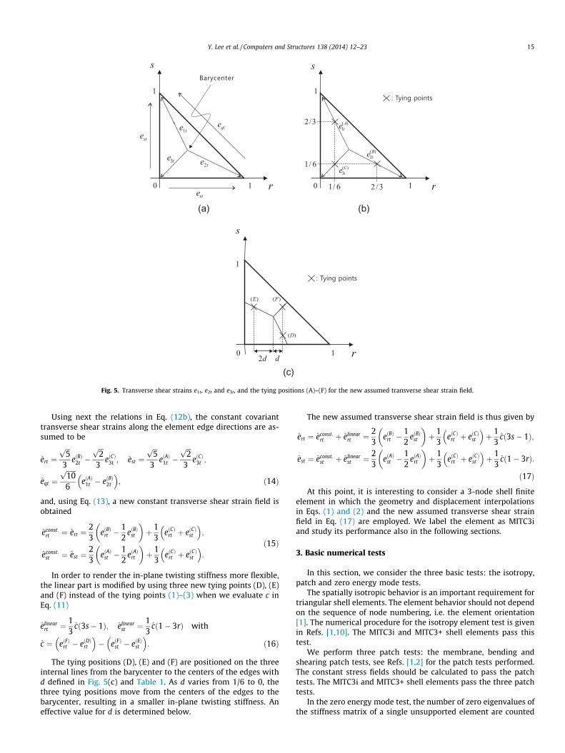
(a) (b)
(c)
Fig. 5. Transverse shear strains e1t, e2t and e3t, and the tying positions (A)–(F) for the new assumed transverse shear strain field.
Y. Lee et al. / Computers and Structures 138 (2014) 12–23 15
Using next the relations in Eq. (12b), the constant covarianttransverse shear strains along the element edge directions are as-sumed to be
ert ¼ffiffiffi5p
3eðBÞ2t �
ffiffiffi2p
3eðCÞ3t ; est ¼
ffiffiffi5p
3eðAÞ1t �
ffiffiffi2p
3eðCÞ3t ;
eqt ¼ffiffiffiffiffiffi10p
6eðAÞ1t � eðBÞ2t
� �; ð14Þ
and, using Eq. (13), a new constant transverse shear strain field isobtained
econst:rt ¼ ert ¼
23
eðBÞrt �12
eðBÞst
� �þ 1
3eðCÞrt þ eðCÞst
� �;
econst:st ¼ est ¼
23
eðAÞst �12
eðAÞrt
� �þ 1
3eðCÞrt þ eðCÞst
� �:
ð15Þ
In order to render the in-plane twisting stiffness more flexible,the linear part is modified by using three new tying points (D), (E)and (F) instead of the tying points (1)–(3) when we evaluate c inEq. (11)
elinearrt ¼ 1
3cð3s� 1Þ; elinear
st ¼ 13
cð1� 3rÞ with
c ¼ eðFÞrt � eðDÞrt
� �� eðFÞst � eðEÞst
� �: ð16Þ
The tying positions (D), (E) and (F) are positioned on the threeinternal lines from the barycenter to the centers of the edges withd defined in Fig. 5(c) and Table 1. As d varies from 1/6 to 0, thethree tying positions move from the centers of the edges to thebarycenter, resulting in a smaller in-plane twisting stiffness. Aneffective value for d is determined below.
The new assumed transverse shear strain field is thus given by
ert ¼ econst:rt þ elinear
rt ¼ 23
eðBÞrt �12
eðBÞst
� �þ 1
3eðCÞrt þ eðCÞst
� �þ 1
3cð3s� 1Þ;
est ¼ econst:st þ elinear
st ¼ 23
eðAÞst �12
eðAÞrt
� �þ 1
3eðCÞrt þ eðCÞst
� �þ 1
3cð1� 3rÞ:
ð17Þ
At this point, it is interesting to consider a 3-node shell finiteelement in which the geometry and displacement interpolationsin Eqs. (1) and (2) and the new assumed transverse shear strainfield in Eq. (17) are employed. We label the element as MITC3iand study its performance also in the following sections.
3. Basic numerical tests
In this section, we consider the three basic tests: the isotropy,patch and zero energy mode tests.
The spatially isotropic behavior is an important requirement fortriangular shell elements. The element behavior should not dependon the sequence of node numbering, i.e. the element orientation[1]. The numerical procedure for the isotropy element test is givenin Refs. [1,10]. The MITC3i and MITC3+ shell elements pass thistest.
We perform three patch tests: the membrane, bending andshearing patch tests, see Refs. [1,2] for the patch tests performed.The constant stress fields should be calculated to pass the patchtests. The MITC3i and MITC3+ shell elements pass the three patchtests.
In the zero energy mode test, the number of zero eigenvalues ofthe stiffness matrix of a single unsupported element are counted
16 Y. Lee et al. / Computers and Structures 138 (2014) 12–23
[1,2]. For the MITC3i and MITC3+ shell elements, only the six zeroeigenvalues corresponding to the six rigid body modes areobtained when the distance d defined for the tying positions (D),(E) and (F) in Fig. 5(c) is non-zero. As d approaches 0, theeigenvalue corresponding to the in-plane twisting mode in Fig. 4decreases and is zero when d = 0.
A similar phenomenon was investigated for the MITC3-HR shellelement in Ref. [10], where it was shown that by decreasing thestiffness for the in-plane twisting mode, it is possible to improvethe performance of 3-node shell elements. Therefore, we performthe in-plane twisting mode test given in Ref. [10] and investigatethe effect of the distance d.
Fig. 6. Strain energy stored in the MITC3i and MITC3+ shell elements depending onthe distance d in the in-plane twisting mode. Since the strain energy is proportionalto t � L2 in the in-plane twisting mode, Et is the strain energy normalized by t � L2.
Table 2Eigenvalues of the stiffness matrix of the single MITC3i shell element for the element geoeigenvalues corresponding to rigid body modes.
Mode d = 1/6 d = 1/10
7 6.6764E�07 B 6.6764E�07 B8 8.1455E�07 B 8.1455E�07 B9 2.4924E�06 B 2.4924E�06 B10 3.6928E+01 T 1.3302E+01 T11 4.6707E+02 S 4.6681E+02 S12 8.3813E+02 M 8.3813E+02 M13 1.1760E+03 S 1.1760E+03 S14 1.3440E+03 M 1.3440E+03 M15 3.0019E+03 M 3.0019E+03 M
B: bending modes, T: in-plane twisting mode, S: transverse shearing modes, M: membr
Table 3Eigenvalues of the stiffness matrix of the single MITC3+ shell element for the element geeigenvalues corresponding to rigid body modes.
Mode d = 1/6 d = 1/10
7 6.6685E�07 B 6.6685E�07 B8 8.1273E�07 B 8.1273E�07 B9 2.4921E�06 B 2.4921E�06 B10 8.3211E�06 B+ 8.3211E�06 B+11 1.4128E�05 B+ 1.4128E�05 B+12 3.6928E+01 T 1.3302E+01 T13 4.6707E+02 S 4.6681E+02 S14 8.3813E+02 M 8.3813E+02 M15 1.1760E+03 S 1.1760E+03 S16 1.3440E+03 M 1.3440E+03 M17 3.0019E+03 M 3.0019E+03 M
B: bending modes, T: in-plane twisting mode, S: transverse shearing modes, M: membr
We calculate the strain energies (Et) of the MITC3i and MITC3+shell elements when the elements are subjected to the in-planetwisting mode in Fig. 4. We use L = 1.0, E = 1.7472 � 107 andm = 0.3. The in-plane twisting mode is given by prescribing therotations at the nodes to be h1
x ¼ h3x ¼ h1
y ¼ h2y ¼ 1=
ffiffiffiffiffiffi12p
and
h2x ¼ h3
y ¼ �2=ffiffiffiffiffiffi12p
. Fig. 6 gives the strain energies of the MITC3iand MITC3+ shell elements as a function of the distance d. Whenthe distance d approaches zero, both shell elements become rap-idly more flexible in the in-plane twisting mode.
Tables 2 and 3 present the eigenvalues of the stiffness matricesof the MITC3i and MITC3+ shell elements for the element geometryshown in Fig. 4(a). We consider t/L = 1/10, 000, E = 1.7472 � 107
and m = 0.3. The eigenvalue corresponding to the in-plane twistingmode decreases as the distance d decreases but is larger than thesmallest eigenvalue of a bending mode. Based on this study wechoose and always use the distance d = 1/10,000. As a consequence,the element formulation contains no spurious zero energy mode,and the ellipticity condition is satisfied. Note that, due to the bub-ble function enrichment, the MITC3+ shell element contains twoadditional bending modes compared to the MITC3i shell element.
4. Convergence studies
In this section, we perform convergence studies using appropri-ate benchmark problems to study the behavior of shell elements: aclamped square plate problem, a sixty-degree skew plate problem,cylindrical shell problems, and hyperboloid shell problems[1–3,30]. These problem solutions pertain to measuring the errorsin an appropriate norm considering membrane and bendingdominated problems with various shell curvatures, shell thicknessvalues, and boundary conditions.
To measure the error in the finite element solution, we use thes-norm proposed by Hiller and Bathe [31]
metry shown in Fig. 4(a) when t/L = 1/10,000. Note that modes 1 to 6 produce zero
d = 1/100 d = 1/10,000
6.6764E�07 B 6.6764E�07 B8.1454E�07 B 7.9792E�07 B2.4924E�06 B 2.4924E�06 B1.3306E�01 T 1.3583E�05 T4.6667E+02 S 4.6667E+02 S8.3813E+02 M 8.3813E+02 M1.1760E+03 S 1.1760E+03 S1.3440E+03 M 1.3440E+03 M3.0019E+03 M 3.0019E+03 M
ane modes.
ometry shown in Fig. 4(a) when t/L = 1/10,000. Note that modes 1 to 6 produce zero
d = 1/100 d = 1/10,000
6.6685E�07 B 6.6685E�07 B8.1272E�07 B 7.9621E�07 B2.4921E�06 B 2.4921E�06 B8.3211E�06 B+ 8.3107E�06 B+1.4128E�05 B+ 1.3599E�05 T1.3306E�01 T 1.4128E�05 B+4.6667E+02 S 4.6667E+02 S8.3813E+02 M 8.3813E+02 M1.1760E+03 S 1.1760E+03 S1.3440E+03 M 1.3440E+03 M3.0019E+03 M 3.0019E+03 M
ane modes, B+: bending modes due to the bubble function enrichment.
(a) (b)
Fig. 7. Fully clamped square plate problem (L = 1.0, E = 1.7472 � 107, q = 1.0 and m = 0.3) with 2 different 4 � 4 mesh patterns in (a) and (b).
Fig. 8. Convergence curves for the fully clamped square plate problem. The bold line represents the optimal convergence rate. The solid and dotted lines correspond to theresults obtained by the mesh patterns in Fig. 7(a) and (b), respectively.
(a) (b)
Fig. 9. Simply supported sixty-degree skew plate problem (L = 1.0, E = 1.7472 � 107 and m = 0.3). (a) Problem description. (b) Mesh pattern used for N = 4.
Y. Lee et al. / Computers and Structures 138 (2014) 12–23 17

Fig. 10. Convergence curves for the simply supported sixty-degree skew plate problem. The bold line represents the optimal convergence rate.
Fig. 11. Cylindrical shell problem (4 � 4 mesh, L = R = 1.0, E = 2.0 � 105, m = 1/3 andp0 = 1.0).
18 Y. Lee et al. / Computers and Structures 138 (2014) 12–23
k u!� u!hk2s ¼
ZX
D e!TD s!dX with D e!¼ e!� e!h;
Ds*¼ s
*� s!h; ð18Þ
where u! is the exact solution, u!h is the solution of the finite ele-ment discretization, and e! and s! are the strain and stress vectors.The s-norm is suitable to identify whether the finite element formu-lation satisfies the consistency and inf–sup conditions [3,31–33].
Instead of the exact solution u!, an accurate finite element solu-tion using a very fine mesh u!ref can be employed. Then the s-normin Eq. (18) becomes
k u!ref � u!hk2s ¼
ZXref
D e!TD s!dXref with
D e!¼ e!ref � e!h; Ds*¼ s
*
ref � s!h: ð19Þ
To measure the performance of finite elements in shell analyses,it is important to consider decreasing shell thickness values. Wethen use the relative error Eh
Eh ¼k u!ref � u!hk2
s
ku*
ref k2s
: ð20Þ
The optimal convergence behavior of the elements, for the shellproblems considered, is given by
Eh ffi Chk; ð21Þ
in which h is the element size. For a 3-node shell element to be uni-formly optimal, the value of C must be constant, that is, indepen-dent of the shell thickness, and k = 2.
In this study, well-converged reference solutions calculatedusing fine meshes of the MITC9 shell elements are used. The MITC9shell element satisfies the ellipticity and consistency conditionsand shows a good convergence behavior [20,30–34].
4.1. Fully clamped square plate problem
We solve the plate bending problem shown in Fig. 7. A squareplate of dimensions 2L � 2L and uniform thickness t is subjectedto a uniform pressure. All edges are fully clamped (in hardconditions [2]). Due to symmetry, only a one-quarter model isconsidered, with the following boundary conditions: ux = hy = 0along BC, uy = hx = 0 along DC and ux = uy = uz = hx = hy = 0 along ABand AD.
Fig. 8 gives the convergence curves of the MITC3, MITC3i andMITC3+ elements. A 96 � 96 element mesh of the MITC9 shell ele-ment is used to obtain the reference solution. We use N � N ele-ment meshes (N = 4, 8, 16, 32, and 64) to calculate the solutionsusing the triangular shell elements. The element size in the conver-gence curves is h = L/N. The performance of the MITC3+ shell ele-ment is best among them and, practically, uniformly optimal. Theimproved predictive capability of the MITC3i element is observedwhen compared with the performance of the MITC3 element.

Fig. 12. Convergence curves for the clamped cylindrical shell problem. The bold line represents the optimal convergence rate.
(a) (b)
Fig. 14. Distorted mesh patterns (a) for N = 4 and (b) for N = 8.
Fig. 13. Convergence curves for the free cylindrical shell problem. The bold line represents the optimal convergence rate.
Y. Lee et al. / Computers and Structures 138 (2014) 12–23 19
4.2. Simply supported sixty-degree skew plate problem
Here we solve the sixty-degree skew plate bending problemshown in Fig. 9. The simply supported skew plate with its edgesof length 2L and uniform thickness t is subjected to a uniformpressure. The boundary condition uz = 0 is imposed along all edges[30].
The convergence behavior of the MITC3, MITC3i and MITC3+shell elements is shown in Fig. 10. The reference solutions are ob-tained using a 128 � 128 element mesh of MITC9 shell elements.The solutions of the triangular shell elements are calculated usingN � N element meshes (N = 8, 16, 32, 64 and 128). The element sizeis h = 2L/N. The performance of the MITC3+ shell element is muchbetter than those of the other elements.
4.3. Cylindrical shell problems
We consider the cylindrical shell of length 2L, radius R and uni-form thickness t as shown in Fig. 11. The loading is a smoothlyvarying pressure p(h)
pðhÞ ¼ p0 cosð2hÞ: ð22Þ
This shell structure shows different asymptotic behaviorsdepending on the boundary conditions at its ends. When both endsare free, a bending dominated problem is solved, whereas when bothends are clamped, a membrane dominated problem is considered.

20 Y. Lee et al. / Computers and Structures 138 (2014) 12–23
Using symmetry, only the region ABCD in Fig. 11 is modeled. Tohave the membrane dominated problem, the clamped boundarycondition is imposed: ux = b = 0 along BC, uy = a = 0 along DC,uz = a = 0 along AB, and ux = uy = uz = a = b = 0 along AD. To havethe bending dominated problem, the free boundary condition isimposed: ux = b = 0 along BC, uy = a = 0 along DC, and uz = a = 0along AB.
Figs. 12 and 13 give the convergence curves of the MITC3, MIT-C3i and MITC3+ shell elements for the clamped and free cylindricalshell problems. The reference solutions are calculated using a96 � 96 element mesh of MITC9 shell elements. The solutionsusing the MITC3, MITC3i and MITC3+ shell elements are obtainedwith N � N element meshes (N = 4, 8, 16, 32, and 64). The elementsize is h = L/N. In these problem solutions, the MITC3, MITC3i andMITC3+ shell elements present similarly good convergencebehaviors.
We then perform the convergence studies with the distortedmeshes shown in Fig. 14. When an N � N element mesh is used,each edge is discretized in the following ratio: L1:L2:L3:. . .LN = 1:2:3: . . .N. Figs. 15 and 16 show the convergence curves
Fig. 15. Convergence curves for the clamped cylindrical shell problem with the distorte
Fig. 16. Convergence curves for the free cylindrical shell problem with the distorted
for the clamped and free cylindrical shell problems, respectively.The MITC3+ shell element shows an excellent performance.
4.4. Hyperboloid shell problems
Finally, we consider the hyperboloid shell shown in Fig. 17. Themid-surface of the shell structure is given by
x2 þ z2 ¼ 1þ y2; y 2 ½�1; 1 �: ð23Þ
As for the cylindrical shell problems, a smoothly varying pres-sure is applied, see Fig. 11,
pðhÞ ¼ p0 cosð2hÞ: ð24Þ
A bending dominated behavior is obtained with free ends and amembrane dominated behavior is given with clamped ends. Thebending dominated problem is known to be difficult to solve accu-rately [3].
Due to symmetry, the analyses are performed using one-eighthof the structure corresponding to the shaded region ABCD in
d meshes shown in Fig. 14. The bold line represents the optimal convergence rate.
meshes shown in Fig. 14. The bold line represents the optimal convergence rate.
(a)
(b)
Fig. 17. Hyperboloid shell problem (E = 2.0 � 1011, m = 1/3 and p0 = 1.0). (a) Problem description. (b) Graded mesh for the clamped case (8 � 8 mesh, t/L = 1/1000).
Fig. 18. Convergence curves for the clamped hyperboloid shell problem. The bold line represents the optimal convergence rate.
Y. Lee et al. / Computers and Structures 138 (2014) 12–23 21
Fig. 17(a). For the membrane dominated case, the clampedboundary condition is imposed: uz = b = 0 along BC, ux = b = 0 alongAD, and uy = a = 0 along DC, and ux = uy = uz = a = b = 0 along AB.For the bending dominated case, the free boundary condition isimposed: uz = b = 0 along BC, ux = b = 0 along AD, and uy = a = 0along DC.
In both cases, a 96 � 96 element mesh of MITC9 shell elementsis used to obtain the reference solutions. The solutions of theMITC3, MITC3i and MITC3+ shell elements are calculated usingN � N element meshes (N = 4, 8, 16, 32 and 64). The element sizeis h = L/N. In the clamped hyperboloid shell case, a boundary layerof width 6
ffiffitp
is considered for half of the mesh, see Fig. 17(b). Inthe free hyperboloid shell case, the thin boundary layer is notspecially considered [3].
Figs. 18 and 19 show the convergence curves for the clampedand free hyperboloid shell problems. In the clamped hyperboloidshell case, the performance of all three shell elements is similarlygood. However, in the free hyperboloid shell case, the MITC3+ shellelement shows a much better convergence behavior compared tothe others.
Figs. 20 and 21 give the convergence curves of the MITC3, MIT-C3i and MITC3+ shell elements when the distorted meshes inFig. 14 are used. The MITC3+ shell element displays even here anexcellent convergence behavior.
We finally note that, in all the numerical studies in Sections 3and 4, the standard 7-point Gauss integration is employed to calcu-late the stiffness matrix of the MITC3+ shell element [2]. If thestandard 3-point Gauss integration is used for the MITC3+ shell
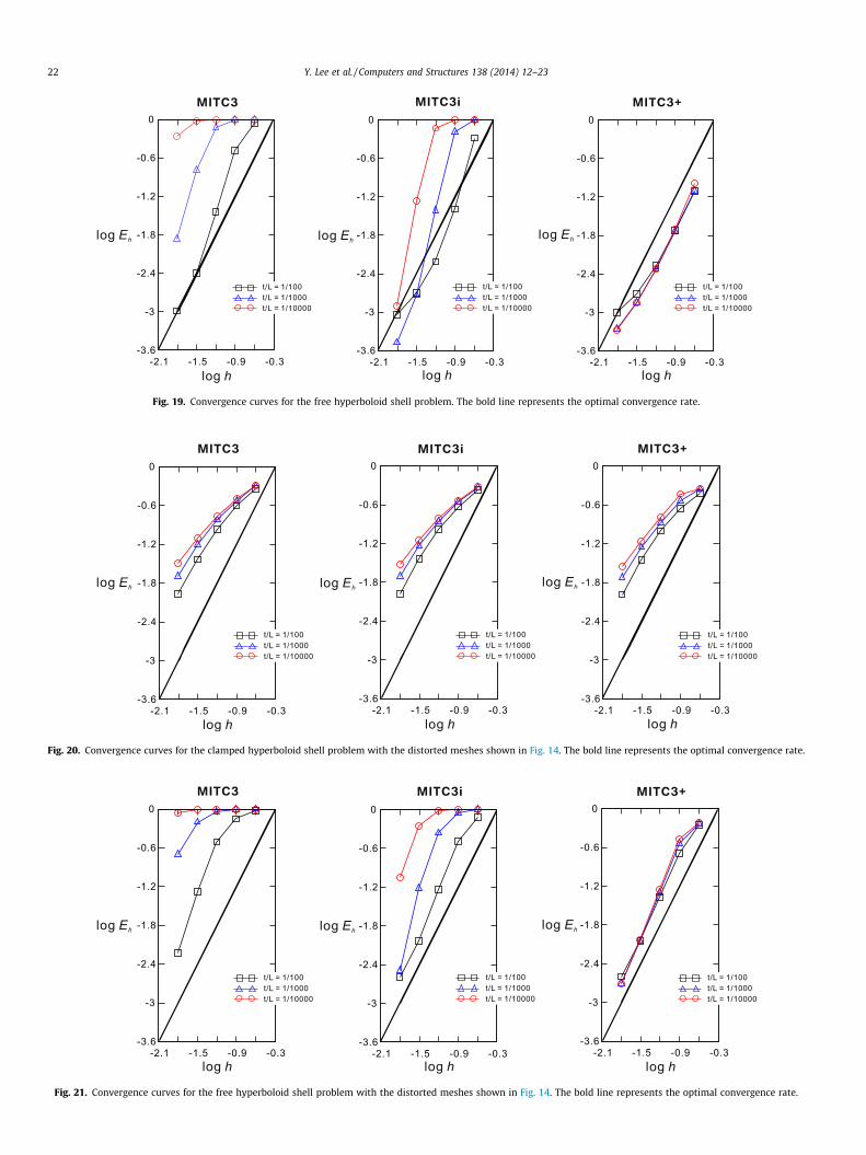
Fig. 19. Convergence curves for the free hyperboloid shell problem. The bold line represents the optimal convergence rate.
Fig. 20. Convergence curves for the clamped hyperboloid shell problem with the distorted meshes shown in Fig. 14. The bold line represents the optimal convergence rate.
Fig. 21. Convergence curves for the free hyperboloid shell problem with the distorted meshes shown in Fig. 14. The bold line represents the optimal convergence rate.
22 Y. Lee et al. / Computers and Structures 138 (2014) 12–23
Y. Lee et al. / Computers and Structures 138 (2014) 12–23 23
element, all the basic numerical tests are also passed and similarconvergence behaviors are observed.
5. Concluding remarks
In this study, we developed a new triangular shell element thatshows considerable promise for general use. The MITC3+ elementis based on the ‘basic mathematical shell model’ [3,35] and theMITC approach used for the development of triangular elements[1] but using a cubic bubble function for the rotations and a newassumed transverse shear strain field. For comparison, we alsoconsidered a shell element, in which the standard displacementinterpolation of the 3-node shell element and the new assumedtransverse shear strain field are used.
All shell elements considered pass the basic numerical tests, theisotropy, zero energy mode, and patch tests, and the MITC3+ shellelement shows an excellent convergence behavior, even whenusing distorted element meshes. While only linear analysis condi-tions have been considered, the element formulation can directlybe extended for large deformation analyses since only the usualMITC procedure has been used. In this paper, the effectiveness ofthe MITC3+ shell element was demonstrated only numerically,and a mathematical analysis would be very valuable to obtain fur-ther insight into the element behavior.
Acknowledgments
This work was supported by the Human Resources Develop-ment Program (No. 20134030200300) of the Korea Institute ofEnergy Technology Evaluation and Planning (KETEP) funded bythe Ministry of Trade, Industry and Energy.
References
[1] Lee PS, Bathe KJ. Development of MITC isotropic triangular shell finiteelements. Comput Struct 2004;82:945–62.
[2] Bathe KJ. Finite element procedures. New York: Prentice Hall; 1996.[3] Chapelle D, Bathe KJ. The finite element analysis of shells – fundamentals. 2nd
ed. Berlin: Springer-Verlag; 2011.[4] Batoz JL, Bathe KJ, Ho LW. A study of three-node triangular plate bending
elements. Int J Numer Methods Eng 1980;15:1771–812.[5] Felippa CA, Bergan PG. A triangular bending element based on an energy-
orthogonal free formulation. Comput Methods Appl Mech Eng1987;61:129–60.
[6] Bletzinger KU, Bischoff M, Ramm E. A unified approach for shear-locking-freetriangular and rectangular shell finite elements. Comput Struct2000;75:321–34.
[7] Argyris JH, Papadrakakis M, Apostolopoulou C, Koutsourelakis S. The TRIC shellelement: theoretical and numerical investigation. Comput Methods Appl MechEng 2000;182:217–45.
[8] Lee PS, Bathe KJ. Insight into finite element shell discretizations by use of the‘‘basic shell mathematical model’’. Comput Struct 2005;83:69–90.
[9] Lee PS, Noh HC, Bathe KJ. Insight into 3-node triangular shell finite elements:the effects of element isotropy and mesh patterns. Comput Struct2007;85:404–18.
[10] Lee Y, Yoon K, Lee PS. Improving the MITC3 shell finite element by using theHellinger–Reissner principle. Comput Struct 2012;110–111:93–106.
[11] Bathe KJ, Lee PS. Measuring the convergence behavior of shell analysisschemes. Comput Struct 2011;89:285–301.
[12] Chapelle D, Bathe KJ. Fundamental considerations for finite element analysis ofshell structures. Comput Struct 1998;66:711–2. 19–36.
[13] Baiocchi C, Lovadina C. A shell classification by interpolation. Math ModelsMethods Appl Sci 2002;12(10):1359–80.
[14] Lee PS, Bathe KJ. On the asymptotic behavior of shell structures and theevaluation in finite element solutions. Comput Struct 2002;80:235–55.
[15] Beirão da Veiga L. Asymptotic energy behavior of two classical intermediatebenchmark shell problems. Math Models Methods Appl Sci2003;13:1279–302.
[16] Bathe KJ, Chapelle D, Lee PS. A shell problem ‘highly sensitive’ to thicknesschanges. Int J Numer Methods Eng 2003;57:1039–52.
[17] Dvorkin EN, Bathe KJ. A continuum mechanics based four-node shell elementfor general nonlinear analysis. Eng Comput 1984;1:77–88.
[18] Bathe KJ, Dvorkin EN. A formulation of general shell elements – the use ofmixed interpolation of tensorial components. Int J Numer Methods Eng1986;22:697–722.
[19] Bucalem ML, Bathe KJ. Higher-order MITC general shell elements. Int J NumerMethods Eng 1993;36:3729–54.
[20] Bathe KJ, Lee PS, Hiller JF. Towards improving the MITC9 shell element.Comput Struct 2003;81:477–89.
[21] Kim DN, Bathe KJ. A triangular six-node shell element. Comput Struct2009;87:1451–60.
[22] Jeon HM, Lee PS, Bathe KJ. The MITC3 shell finite element enriched byinterpolation covers. Comput Struct 2014;134:128–42.
[23] Wilson EL, Ibrahimbegovic A. Use of incompatible displacement modes for thecalculation of element stiffness or stresses. Finite Elem Anal Des1990;7:229–41.
[24] Arnold DN, Brezzi F, Fortin M. A stable finite element for the Stokes equations.Estratto da Calcolo 1984;21:337–44.
[25] Kim J, Bathe KJ. The finite element method enriched by interpolation covers.Comput Struct 2013;116:35–46.
[26] Kohno H, Bathe KJ. A flow-condition-based interpolation finite elementprocedure for triangular grids. Int J Numer Methods Fluids 2006;51:673–99.
[27] Pinsky PM, Jasti RV. A mixed finite element formulation for Reissner–Mindlinplates based on the use of bubble functions. Int J Numer Methods Eng1989;28:1667–702.
[28] Hong WI, Kim YH, Lee SW. An assumed strain triangular solid element withbubble function displacements for analysis of plates and shells. Int J NumerMethods Eng 2001;52:455–69.
[29] Ho SP, Yeh YL. The use of 2D enriched elements with bubble functions for finiteelement analysis. Comput Struct 2006;84:2081–91.
[30] Lee PS, Bathe KJ. The quadratic MITC plate and MITC shell elements in platebending. Adv Eng Software 2010;41:712–28.
[31] Hiller JF, Bathe KJ. Measuring convergence of mixed finite elementdiscretizations: an application to shell structures. Comput Struct2003;81:639–54.
[32] Bathe KJ, Iosilevich A, Chapelle D. An inf–sup test for shell finite elements.Comput Struct 2000;75:439–56.
[33] Bathe KJ. The inf–sup condition and its evaluation for mixed finite elementmethods. Comput Struct 2001;79(243-52):971.
[34] Bathe KJ, Brezzi F, Marini LD. The MTC9 shell element in plate bending:mathematical analysis of a simplified case. Comput Mech 2011;47:617–26.
[35] Chapelle D, Bathe KJ. The mathematical shell model underlying general shellelements. Int J Numer Methods Eng 2000;48:289–313.