the model fs102/fs104/fs108 switch has the ... - newegg · another switch or hub using a standard,...
TRANSCRIPT


lupport
es areisted
tch)ationndard
Theith as
leseive
ffic
and
d to
ectorS108
ast
r-desk
Congratulations on your purchase of the NETGEAR™ Model FS102, Model FS104, or ModeFS108 Fast Ethernet Switch—a low-cost, high-performance network solution designed to spower workgroups operating at 10 megabits per second (Mbps) or 100 Mbps.
In this installation guide that describes how to install and use the switches, all three switchreferred to collectively as the Model FS102/FS104/FS108 switch. Each switch is lindividually when information is provided that refers to a specific model.
The Model FS102/FS104/FS108 switch has the following features:
• Two (Model FS102 switch), four (Model FS104 switch), and eight (Model FS108 swivista automatic speed-sensing 10/100 Mbps Ethernet ports that provide fast informexchange, resource sharing, and client or peer-to-peer communication using staCategory 5 unshielded twisted pair (UTP) cable
• Automatic address learning function to build the packet forwarding information table (table contains up to 8,000 MAC addresses; that is, the switch can support networks wmany as 8,000 devices.)
• Autosensing full-duplex or half-duplex mode of operation (Full-duplex mode doubthroughput of point-to-point connections by letting individual ports transmit and recconcurrently when the connecting device also supports full-duplex mode.)
• Wire-speed filtering and forwarding to support the “traffic cop” function by directing trato the appropriate port or network segment without slowing down the traffic
• Easy plug-and-play installation with no software to configure, which saves time minimizes the potential for configuration errors
• Normal/Uplink push button to simplify network extension (The switch can be connecteanother switch or hub using a standard, straight-through cable.)
• Two vista RJ-45 connector ports on the Model FS102 switch, four vista RJ-45 connports on the Model FS104 switch, and eight vista RJ-45 connector ports on the Model Fswitch (Each port has built-in LEDs to monitor individual port status.)
• LEDs that provide network traffic status and data transmission speed• IEEE 8023u standard compliance, allowing incorporation with other 100BASE-TX F
Ethernet (100 Mbps) products• IEEE 802.3 10BASE-T standard compliance• Compact, sturdy metal case design that enables easy desktop, wall-mount, or unde
installation
Start Here
Features
Model FS102, Model FS104, Model FS108 Fast Ethernt Switch Installation Guide
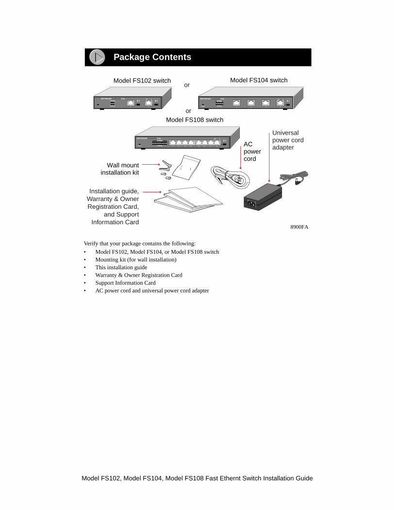
Verify that your package contains the following:
• Model FS102, Model FS104, or Model FS108 switch• Mounting kit (for wall installation)• This installation guide• Warranty & Owner Registration Card• Support Information Card• AC power cord and universal power cord adapter
Package Contents
8900FA
Universalpower cordadapter
Wall mountinstallation kit
Installation guide,Warranty & OwnerRegistration Card,
and SupportInformation Card
Model FS108 switch
Model FS102 switch Model FS104 switchor
or
ACpowercord
1
1 2 3 4 5 6 7 8
2 3 4 5 6 7 8Power Collision
100 MbpsLINK RxFS108FAST ETHERNET SWITCH
2
FS102FAST ETHERNET SWITCH LINK Rx
1
1 2
Collision
100 Mbps
1
1 2 3 4
2 3Power Collision
100 Mbps
FS104FAST ETHERNET SWITCH LINK Rx
4
Model FS102, Model FS104, Model FS108 Fast Ethernt Switch Installation Guide

for the
.
Fast Ethernet Vista Ports with Built-in LEDsAll of the ports on the switch are 10/100 Mbps Ethernet ports. The network access speed ports is automatically sensed and displayed on the front panel by the 100 Mbps LEDs.
Each port supports only unshielded twisted pair (UTP) cable using an 8-pin RJ-45 plug.
Each port uses vista RJ-45 connectors that have two LEDs—the Link LED and the FDX LED
Product Illustration
8899FA
Front Panel of the Model FS102 switch
Front Panel of the Model FS108 switch
1
1 2 3 4 5 6 7 8
2 3 4 5 6 7 8Power Collision
100 MbpsLINK RxFS108FAST ETHERNET SWITCH
Power 2
FS102FAST ETHERNET SWITCH LINK Rx
1
1 2
Collision
100 Mbps
100 Mbps ports
Normal/Uplinkpush button
Power
Front Panel of the Model FS104 switch
1
1 2 3 4
2 3Power Collision
100 Mbps
FS104FAST ETHERNET SWITCH LINK Rx
4
8724EB
LinkLED
FDXLED
Model FS102, Model FS104, Model FS108 Fast Ethernt Switch Installation Guide

LEDsThis table describes the activity of the Model FS102/FS104/FS108 switch LEDs.
Label Color Activity Description
Pwr (Power) Green OnOff
Power is supplied to the switch.Power is disconnected.
Rx/Tx/Collision Green
Yellow
Blinking
Blinking
Packet transmission or reception is occurring on the port. Data collisions are occurring on the port. The blinking action corresponds to the number of collisions. When a collision occurs, the connected device pauses and transmits again after waiting a specified time. Note that occasional collisions are normal.
100 Mbps Green On
Off
The port is operating at 100 Mbps.The port is operating at 10 Mbps.
Link(located at the top left corner of each vista 10BASE-T port)
Green On
Off
A valid link is established on the port.A link is not established on the port.
FDX(located at the top right corner of each vista10BASE-T port)
Green On
Off
The port is operating in full-duplex mode.The port is operating in half-duplex mode.
Model FS102, Model FS104, Model FS108 Fast Ethernt Switch Installation Guide

DI) ond for
tton is hub,
uplex
t ands (for
uplexll- orannotlts toationshould
mode
Normal/Uplink Push ButtonThe Normal/Uplink push button on the front panel of the switch allows you to select uplink (Mor normal (MDI-X) wiring for either of the Ethernet ports on the Model FS102 switch, port 4the Model FS104 switch, or port 8 on the Model FS108 switch. These ports are configurenormal wiring to connect to a PC when the push button position is out. When the push bupressed in, these ports are configured for uplink wiring to connect to another switch or to ausing a straight-through twisted pair cable.
Rear PanelThe rear panel of the Model FS102/FS104/FS108 switch has full-duplex (FDX) and auto-d(AUTO) toggle switches and a power adapter receptacle for the supplied power adapter.
FDX/AUTO Duplex Toggle SwitchesFull-duplex mode is supported for all 10/100 Mbps ports and allows the port to transmireceive data at the same time. Full-duplex operation applies only to point-to-point accesexample, when a switch is connected to a PC, a server, or another switch).
Setting the toggle switch to AUTO on the 10/100 Mbps port enables the port to determine dmode automatically. In this mode of operation, the 10/100 Mbps port operates in either fuhalf-duplex, depending on the operating mode of the remote port. If the remote port cprovide the proper signal to indicate its capability, the 10/100 Mbps port on the switch defauhalf-duplex mode. Repeaters and hubs use a common collision domain for all communicand cannot communicate in full-duplex mode. The associated 10 Mbps port on the switch sbe set to auto-duplex operation when connecting to these types of devices.
One toggle switch is assigned to each 10/100 Mbps port and can be set to full-duplex (FDX)or auto-duplex (AUTO) mode.
12Vdc 1.2A
– +
12Vdc 1.2A
– +
8901FA
Rear Panel of the Model FS102 switch
Rear Panel of the Model FS104 switch
Rear Panel of the Model FS108 switch
Power receptacle
1 4FDXAUTO
10/100 Mbps
FDX -
AUTO -
Force port to operate at Full Duplex and Half Duplex mode.
Enable port to determine duplex mode automatically. Default is Half Duplex.
12Vdc 1.2A
– +
1 2 3 4 5 6 7 8FDXAUTO
10/100 Mbps
FDX -
AUTO -
Force port to operate at Full Duplex and Half Duplex mode.
Enable port to determine duplex mode automatically. Default is Half Duplex.
1 2FDXAUTO
10/100 MbpsFDX -
AUTO -
Force port to operate at Full Duplex and Half Duplex mode.
Enable port to determine duplex mode automatically. Default is Half Duplex.
Model FS102, Model FS104, Model FS108 Fast Ethernt Switch Installation Guide

our0 Mbps
rationents
tions other
etwork
sers to
ble on
The Model FS102/FS104/FS108 switch is designed to provide flexibility in configuring ynetwork connections. Each switch can be used as a standalone device or can be used with 1or 100 Mbps hubs or other interconnection devices in various configurations. The configuexamples in this section illustrate the integration of the switches in various network environmusing other NETGEAR products. These examples include a network of a few workstaconnected to a printer or a segmented network with multiple users or workgroups andnetworking devices.
Although the examples illustrate specific switches, any of the switches can be used in the nconfigurations shown.
Desktop SwitchingThe Model FS108 switch is used as a desktop switch to build a small network that enables uhave 100 Mbps access to a file server.
If a full-duplex adapter card is installed in the server or PC, a 200 Mbps connection is possithe port where the server or PC is connected.
Applications
1
1 2 3 4 5 6 7 8
2 3 4 5 6 7 8Power Collision
100 MbpsLINK RxFS108FAST ETHERNET SWITCH
Model FS108 switch
100 Mbps
10 Mbps
8902FA
Key
Model FS102, Model FS104, Model FS108 Fast Ethernt Switch Installation Guide

ectedgment
) for a by 200del
Segment SwitchingThe Model FS108 switch is used as a switch that segments a network into multiple connpieces, increasing overall bandwidth and throughput. The Model FS108 switch can senetworks that are built with the NETGEAR Model DS108 Dual Speed Hubs.
Extending a Network DiameterEthernet specifications limit the length of cable between hubs and PCs to 100 meters (mtotal of 200 meters. By adding Fast Ethernet switches between hubs, a network is expandedmeters with the addition of each switch. The illustration below shows two NETGEAR MoFE108 Fast Ethernet Hubs integrated with a Model FS108 switch to extend a network.
1
1 2 3 4 5 6 7 8
2 3 4 5 6 7 8Power Collision
100 MbpsLINK RxFS108FAST ETHERNET SWITCH
Auto 10/100 MbpsDUAL SPEED Auto 10/100 MbpsDUAL SPEED
Model FS108 switch
Model DS108 hubModel DS108 hub
8903FA
1
1 2 3 4 5 6 7 8
2 3 4 5 6 7 8Power Collision
100 MbpsLINK RxFS108FAST ETHERNET SWITCH
Model FS108 switch
100 m
8904FA
Model FE108hubs
Model FS102, Model FS104, Model FS108 Fast Ethernt Switch Installation Guide
E-Ttworkork byrnet
tworkcation occurices towith ab. A
imum
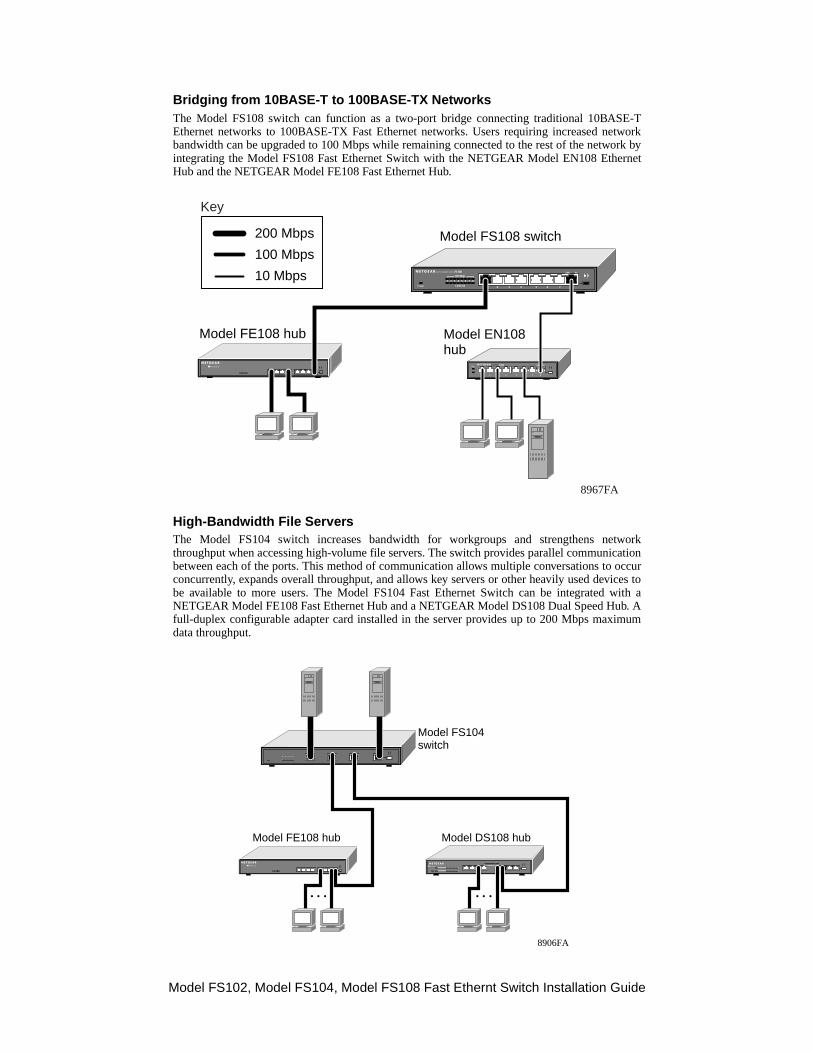
Bridging from 10BASE-T to 100BASE-TX NetworksThe Model FS108 switch can function as a two-port bridge connecting traditional 10BASEthernet networks to 100BASE-TX Fast Ethernet networks. Users requiring increased nebandwidth can be upgraded to 100 Mbps while remaining connected to the rest of the netwintegrating the Model FS108 Fast Ethernet Switch with the NETGEAR Model EN108 EtheHub and the NETGEAR Model FE108 Fast Ethernet Hub.
High-Bandwidth File ServersThe Model FS104 switch increases bandwidth for workgroups and strengthens nethroughput when accessing high-volume file servers. The switch provides parallel communibetween each of the ports. This method of communication allows multiple conversations toconcurrently, expands overall throughput, and allows key servers or other heavily used devbe available to more users. The Model FS104 Fast Ethernet Switch can be integrated NETGEAR Model FE108 Fast Ethernet Hub and a NETGEAR Model DS108 Dual Speed Hufull-duplex configurable adapter card installed in the server provides up to 200 Mbps maxdata throughput.
1
1 2 3 4 5 6 7 8
2 3 4 5 6 7 8Power Collision
100 MbpsLINK RxFS108FAST ETHERNET SWITCH
1 2 3 4 5 6 7 8
Pwr
Col
EN10810 BASE-T HUB LINK Rx
Model EN108hub
Model FE108 hub
8967FA
Model FS108 switch200 Mbps
100 Mbps
10 Mbps
Key
Auto 10/100 MbpsAuto 10/100 MbpsDUAL SPEED
Model FS104switch
Model FE108 hub Model DS108 hub
8906FA
Model FS102, Model FS104, Model FS108 Fast Ethernt Switch Installation Guide

ating
itch is
ack oft thetents.et, and
riate
le for2 on
S108
red
red
aretwisted for
the
Before you begin installing your switch, prepare the installation site. Make sure your operenvironment meets the operating environment requirements of the equipment.
To install your switch on a flat surface, you do not need any special tools. Be sure the swpositioned with at least 2 inches of space on all sides for ventilation.
To install the switch on a wall, measure the distance between the mounting holes on the bthe switch and mark the wall to match the location of the mounting holes on the switch. Amarks, screw into the wall the two screws in the mounting kit included in your package conChoose a location that is near the devices to be connected, is close to an electrical outlprovides at least 2 inches of space all around the switch for ventilation.
Before connecting the switch, be sure you review “Applications” for to determine the appropconfiguration for your networking needs.
To connect the switch:
1. Connect the devices to the 10/100 Mbps ports on the switch, using Category 5 UTP cable and an RJ-45 plug.
2. Set the Normal/Uplink push button.
The Normal/Uplink push button eliminates the need to use a crossover twisted pair cabdaisy-chaining or cascading. Use the following guidelines to configure port 1 and port the Model FS102 switch, port 4 on the Model FS104 switch, or port 8 on the Model Fswitch for uplink or normal wiring:
• Configure the port for normal wiring if the port is to be connected to an uplink-widevice, such as a network station or a PC.
• Configure the port for uplink wiring if the port is to be connected to a normal-widevice, such as a 100 Mbps hub or another switch.
The remaining (normal) ports on the switch cannot be configured for uplink wiring. If youusing one of these ports to connect to another normal port, you must use a crossover pair cable to connect the two ports. Refer to “Cable and Connector Information”information about crossover twisted pair cable and straight-through twisted pair cable.
Characteristic Requirement
Temperature Ambient temperature between 0q and 40q C (32q and 104q F).No nearby heat sources such as direct sunlight, warm air exhausts, or heaters.
Operating humidity Maximum relative humidity of 90%, noncondensing.
Ventilation Minimum 2 inches (5.08 cm) on all sides for cooling.Adequate airflow in room or wiring closet.
Operating conditions At least 6 feet (1.83 m) to nearest source of electromagnetic noise (such as photocopy machine or arc welder).
Power Adequate power source within 6 feet (1.83 m).
Note: Ethernet specifications limit the cable length between your PC or server and switch to 328 feet (100 meters).
Prepare the Site
Install the Switch
Connect Devices to the Switch
Model FS102, Model FS104, Model FS108 Fast Ethernt Switch Installation Guide
nnot to a any
ng theg to
ust be
de.odeotiate,lex
lexicesUTOs not
f
bout
3. Set the FDX or AUTO toggle switches on the rear panel for the selected duplex mode.A hub and repeater use a common collision domain for all communications and casupport full-duplex mode. When connecting any of the 10/100 Mbps ports on the switchhub, set the port to AUTO. The switch must also be set to AUTO when connecting todevice that does not use NWay autonegotiation to detect the operating mode. Settitoggle switch to AUTO will cause the port to default to half-duplex mode when connectina port that does not use autonegotiation.
When connecting to a PC, a server, or another switch, the duplex setting for the port mthe same as the duplex setting on the PC, server, or other switch.
To set the 10/100 Mbps ports for the selected duplex mode:
• Move the toggle switch into the down position (to AUTO) for auto-duplex moThe 10/100 Mbps ports will negotiate and automatically determine the duplex mbased on the mode of the connected port. If the connected port cannot autonegthe 10/100 Mbps port will default to half-duplex mode. The factory setting of the duptoggle switches is AUTO.
• Move the toggle switch into the up position (to FDX) for full-duplex mode.The dupswitch must be set to FDX if you are connecting to legacy full-duplex 100 Mbps devthat do not generate signals indicating duplex mode. If the duplex switch is set to Amode, the 10/100 Mbps ports will default to half-duplex mode because the port doereceive the proper signal.
4. Connect one end of the DC power adapter cable to the power outlet on the rear panel othe switch and the other end of the power adapter cable to the wall outlet.
When power has been applied to the switch:
• The green Pwr (Power) LED on the front panel is on.
• The green Link LED on each connected port is on.
When the switch is connected and operating, refer to the table in “LEDs” for information athe LEDs and their activity.
Verify Installation
Model FS102, Model FS104, Model FS108 Fast Ethernt Switch Installation Guide

Symptom Cause Solution
Green Link LED is off on an active port.
Port connection is not functioning.
Make sure the attached device is powered and there is a proper UTP connection at that end.Make sure the network adapter card installed in the PC is in working condition. Verify that the network adapter card is100 Mbps capable and that the 100 Mbps LED and Link LEDs are on at the network adapter card in the PC.Make sure the proper cable is installed, and check for miswired cable pairs or loose connectors.
Green Link LED is intermittent on an active port.
Port connection is not functioning.
Make sure the port termination at both the switch and the device end is correct. Check the crimp on the RJ-45 connectors. In a Fast Ethernet operation, the quality of the crimp on the connector is important. It is also important that only Category 5 cable is used and that it is certified for 100 Mbps operation.Make sure the length of the UTP cable from the switch to the device does not exceed 328 feet (100 meters).Using cable test equipment, make sure the cable meets the crosstalk, attenuation, and impedance specifications as required by the 100BASE-TX standard. Refer to “Cable and Connector Information” for information about cable specifications.
Green Link LED is off on ports 1 or 2 on the Model FS102 switch, port 4 on the Model FS104 switch, or port 8 on the Model FS108 switch.
Port connection is not functioning.
Check the Normal/Uplink push button on the front panel. If you are using a straight-through cable connected to a PC or other MDI-wired device, make sure the Normal/Uplink push button is set in the Normal position.If you are using a straight-through cable connected to a router or another switch, make sure the Normal/Uplink push button is set in the Uplink position.Try the alternate position of the Normal/Uplink push button to turn the Link LED on.Refer to “Cable and Connector Information” for cable information.
Green 100 Mbps LED is off when operating in a Fast Ethernet network.
Port is operating in 10 Mbps mode.
Make sure the adapter card is capable of 100 Mbps operation and set for 100 Mbps operation if it is not autosensing.
Green Link LED is on and Green FDX LED is off when connected to a full duplex network.
Port is operating in half-duplex mode.
Make sure the duplex switch on the Model FS102/FS104/FS108 switch is set for full-duplex operation. Make sure the connected device is capable of full-duplex transmission.
Troubleshooting Information
Model FS102, Model FS104, Model FS108 Fast Ethernt Switch Installation Guide

eceiverf thees withtation
s.
Twisted Pair CablesFor two devices to communicate, the transmitter of each device must be connected to the rof the other device. The crossover function is usually implemented internally as part ocircuitry in the device. Most ports on switches and repeaters have media-dependent interfaccrossover ports. These ports are referred to as MDI-X or normal ports. Computer and worksadapter cards are usually media-dependent interface ports referred to as MDI or uplink port
The figures illustrate the use of straight-through and crossover twisted pair cables.
Yellow Rx/Tx Collision LED is blinking excessively.
Data collision is occurring on the port.
The port and switch might be functioning correctly. However, check the following to make sure that excessive collisions are normal (as in most Ethernet networks) and not caused by:• Incorrect cabling or connectors• Wiring techniques• Mismatched duplex operating mode settings
Green FDX LED is off when you have set the port to operate in full-duplex mode.
Port is operating in half-duplex mode.
Make sure the connected device is able to operate at half-duplex mode and check the specifications of the connected device to make sure it has the ability to signal the operating mode. Verify that the connected device is operational. If the connected device is an adapter card, make sure you have an adapter card that is capable of 100 Mbps operation and set to 100 Mbps if it is not autosensing.
Symptom Cause Solution
Cable and Connector Information
Straight-throughtwisted pair cable
Crossovertwisted pair cable
8146EB
Tx
Uplink orMDI port
Normal orMDI-X port
Normal orMDI-X port
Normal orMDI-X port
Rx
1
2
3
6Tx
Rx1
2
3
6
12
36
12
36
Tx
Rx
Tx
Rx
Model FS102, Model FS104, Model FS108 Fast Ethernt Switch Installation Guide

nectccepts.
RJ-45 ConnectorThe RJ-45 connector (shown in the illustration with an RJ-45 plug) is used to conworkstations and switches through unshielded twisted pair cable. The RJ-45 connector afour-pair Category 3 or Category 5 UTP cable. Only two pairs are used for 10BASE-T wiring
RJ-45 ConnectorPin Assignment
Normal Assignment:
Uplink Assignment:Port 1 or 2 on the Model FS102 SwitchPort 4 on the Model FS104 Switch Port 8 on the Model FS108 Switch
1 Input Receive Data + Output Transmit Data +
2 Input Receive Data - Output Transmit Data -
3 Output Transmit Data + Input Receive Data +
6 Output Transmit Data - Input Receive Data -
4, 5, 7, 8 Not used Not used
711EA
18
12345678
Model FS102, Model FS104, Model FS108 Fast Ethernt Switch Installation Guide

General Specifications Model FS102 Switch Model FS104 Switch Model FS108 Switch
Network Protocol and Standards Compatibility
ISO/IEC 802-3 (ANSI/IEEE 802.3i) 10BASE-T EthernetIEEE 802.3u, IEEE802.3x 100BASE-TX, Fast Ethernet
Data Rate 100 Mbps with 4B/5B encoding and MLT-3 physical interface for 100BASE-TX10 Mbps differential Manchester encoded
Interface RJ-45 connector for 10BASE-T or 100BASE-TX Ethernet interface
Power Consumption 8 W 15.2 W 12 W
Input Voltage (Power Adapter)
12 V dc 12 V dc 5 V dc
Physical Specifications
Dimensions: 6.2 x 1.06 x 4.1 in.15.8 x 2.7 x 10.3 cm
9.27 x 1.06 x 4.1 in.23.5 x 2.7 x 10.3 cm
9.27 x 1.06 x 4.1 in.23.5 x 2.7 x 10.3 cm
Weight: 1.09 lb; 0.50 kg 1.60 lb; 0.73 kg 1.60 lb; 0.73 kg
Environmental Specifications
Operating temperature: 0q to 40q C (32q to 104q F)
Operating humidity: 90% maximum relative humidity, noncondensing
Electromagnetic Emissions
CE mark, commercial; FCC Part 15, Class A; EN 55 022 (CISPR 22), Class A; VCCI Class 1 ITE
Electromagnetic Susceptibility
CE mark, commercial CE mark, commercial CE mark, commercial
Electrostatic discharge (ESD):
IEC 801-2, Level 2/3/4 IEC 801-2, Level 2/3/4 IEC 801-2, Level 2/3/4
Radiated electromagnetic field:
IEC 801-3, Level 2 IEC 801-3, Level 2 IEC 801-3, Level 2
Electrical fast transient/burst: IEC 801-4, Level 2 IEC 801-4, Level 2 IEC 801-4, Level 2
Electrical surge: IEC 801-5, Level 2 IEC 801-5, Level 2 IEC 801-5, Level 2
Safety Agency Approvals for Power Adapter
CE mark, commercialUL listed (UL 1950)CSA certified (CSA 22.2 #950)TUV licensed (EN 60 950)T-Mark
CE mark, commercialUL listed (UL 1950)CSA certified (CSA 22.2 #950)TUV licensed (EN 60 950)T-Mark
CE mark, commercialUL listed (UL 1950)CSA certified (CSA 22.2 #950)TUV licensed (EN 60 950)T-Mark
Performance Specifications
Frame filter rate: 14,800 frames/second, maximum on 10 Mbps port148,000 frames/second, maximum on 100 Mbps port
Frame forward rate: 14,800 frames/second, maximum on 10 Mbps port148,000 frames/second, maximum on 100 Mbps port
Network latency (using 64-byte packets):
10 Mbps to 10 Mbps: 73 microseconds maximum10 Mbps to 100 Mbps: 26 microseconds maximum100 Mbps to 10 Mbps: 62 microseconds maximum100 Mbps to 100 Mbps: 15 microseconds maximum
Address database size: 8,000 media access control (MAC) addresses per port
Addressing: 48-bit MAC address
Queue buffer: 10/100 Mbps ports: 1 MB of buffer space for each port
10/100 Mbps ports: 128 k of buffer space for each
port
Technical Specifications
Model FS102, Model FS104, Model FS108 Fast Ethernt Switch Installation Guide

© 1998 by NETGEAR, Inc. All rights reserved.
TrademarksBay Networks is a registered trademark of Bay Networks, Inc.
NETGEAR is a trademark of Bay Networks, Inc.
All other trademarks and registered trademarks are the property of their respective owners.
Statement of ConditionsIn the interest of improving internal design, operational function, and/or reliability, NETGEAR reserves the right to make changes to the productsdescribed in this document without notice.
NETGEAR does not assume any liability that may occur due to the use or application of the product(s) or circuit layout(s) described herein.
Certificate of the Manufacturer/ImporterIt is hereby certified that the NETGEAR Model FS102/104/108 Fast Ethernet Switch has been suppressed in accordance with the conditions set outin the BMPT-AmtsblVfg 243/1991 and Vfg 46/1992. The operation of some equipment (for example, test transmitters) in accordance with theregulations may, however, be subject to certain restrictions. Please refer to the notes in the operating instructions.
Federal Office for Telecommunications Approvals has been notified of the placing of this equipment on the market and has been granted the rightto test the series for compliance with the regulations.
Voluntary Control Council for Interference (VCCI) StatementThis equipment is in the first category (information equipment to be used in commercial and/or industrial areas) and conforms to the standards setby the Voluntary Control Council for Interference by Data Processing Equipment and Electronic Office Machines that are aimed at preventing radiointerference in commercial and/or industrial areas.
Consequently, when this equipment is used in a residential area or in an adjacent area thereto, radio interference may be caused to equipment suchas radios and TV receivers.
Federal Communications Commission (FCC) Compliance Notice: Radio Frequency Notice
Note: This equipment has been tested and found to comply with the limits for a Class A digital device, pursuant to Part 15 of the FCC rules. Theselimits are designed to provide reasonable protection against harmful interference when the equipment is operated in a commercial environment.This equipment generates, uses, and can radiate radio frequency energy. If it is not installed and used in accordance with the instruction manual, itmay cause harmful interference to radio communications. Operation of this equipment in a residential area is likely to cause harmful interference,in which case users will be required to take whatever measures may be necessary to correct the interference at their own expense.
EN 55 022 StatementThis is to certify that the NETGEAR Model FS102/104/108 Fast Ethernet Switch is shielded against the generation of radio interference inaccordance with the application of Council Directive 89/336/EEC, Article 4a. Conformity is declared by the application of EN 55 022 Class A(CISPR 22).
Canadian Department of Communications Radio Interference RegulationsThis digital apparatus (NETGEAR Model FS102/104/108 Fast Ethernet Switch) does not exceed the Class A limits for radio-noise emissions fromdigital apparatus as set out in the Radio Interference Regulations of the Canadian Department of Communications.
Règlement sur le brouillage radioélectrique du ministère des CommunicationsCet appareil numérique (NETGEAR Model FS102/104/108 Fast Ethernet Switch) respecte les limites de bruits radioélectriques visant les appareilsnumériques de classe A prescrites dans le Règlement sur le brouillage radioélectrique du ministère des Communications du Canada.
This is a Class A product. In a domestic environment, this product may cause radio interference, in which case the user may be required to take appropriate measures.
Model FS102, Model FS104, Model FS108 Fast Ethernt Switch Installation Guide

NETGEAR, Inc.A Bay Networks Company4401 Great America ParkwaySanta Clara, CA 95054 USAPhone: 888-NETGEAR
*M-FS100NA-1*