the monthly journal of the american hacker
TRANSCRIPT

GBPPR 'Zine
Issue #16 / The Monthly Journal of the American Hacker / July 2005
Special Watergate Surveillance Issue. Remember, if there's a place worth breakinginto, it's a Democratic National Committee office.
Table of Contents
Page 2 / Electronic Eavesdropping Techniques and Equipment♦ Copy of DoJ electronic surveillance manual for law enforcement organizations.♦
Page 43 / Nortel DMS−100 Office Parameters Overview♦ Quick overview of the default office settings on a DMS−100.♦
Page 53 / Nortel DMS−100 CDN SERVORD Command♦ How to change someones telephone number under a DMS−100.♦
Page 57 / Spread Spectrum Surveillance Bug♦ Overview of turning a cordless phone into a surveillance bug.♦
Page 66 / "Shotgun" Directional Microphone♦ Construction overview of a multitube directional microphone.♦
Page 85 / Rugged J−Pole Antenna Design♦ Design info for an easy to build, rugged, and portable antenna.♦
Page 92 / Bonus♦ CIA Career Ad: Communications and Radio Operators♦
Page 93 / The End♦ Editorial and rants.♦
1
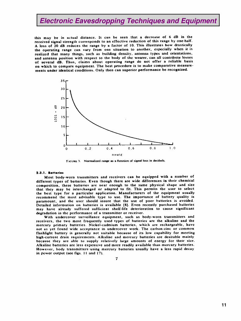
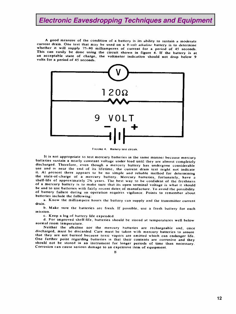
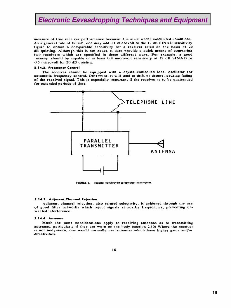
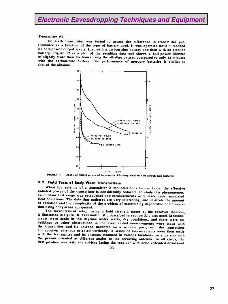
Electronic Eavesdropping Techniques and Equipment
2

Electronic Eavesdropping Techniques and Equipment
3
Electronic Eavesdropping Techniques and Equipment
4
Electronic Eavesdropping Techniques and Equipment
5

Electronic Eavesdropping Techniques and Equipment
6

Electronic Eavesdropping Techniques and Equipment
7

Electronic Eavesdropping Techniques and Equipment
8

Electronic Eavesdropping Techniques and Equipment
9
Electronic Eavesdropping Techniques and Equipment
10
Electronic Eavesdropping Techniques and Equipment
11
Electronic Eavesdropping Techniques and Equipment
12

Electronic Eavesdropping Techniques and Equipment
13

Electronic Eavesdropping Techniques and Equipment
14
Electronic Eavesdropping Techniques and Equipment
15

Electronic Eavesdropping Techniques and Equipment
16

Electronic Eavesdropping Techniques and Equipment
17

Electronic Eavesdropping Techniques and Equipment
18
Electronic Eavesdropping Techniques and Equipment
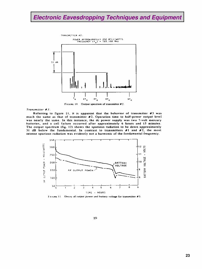
19

Electronic Eavesdropping Techniques and Equipment
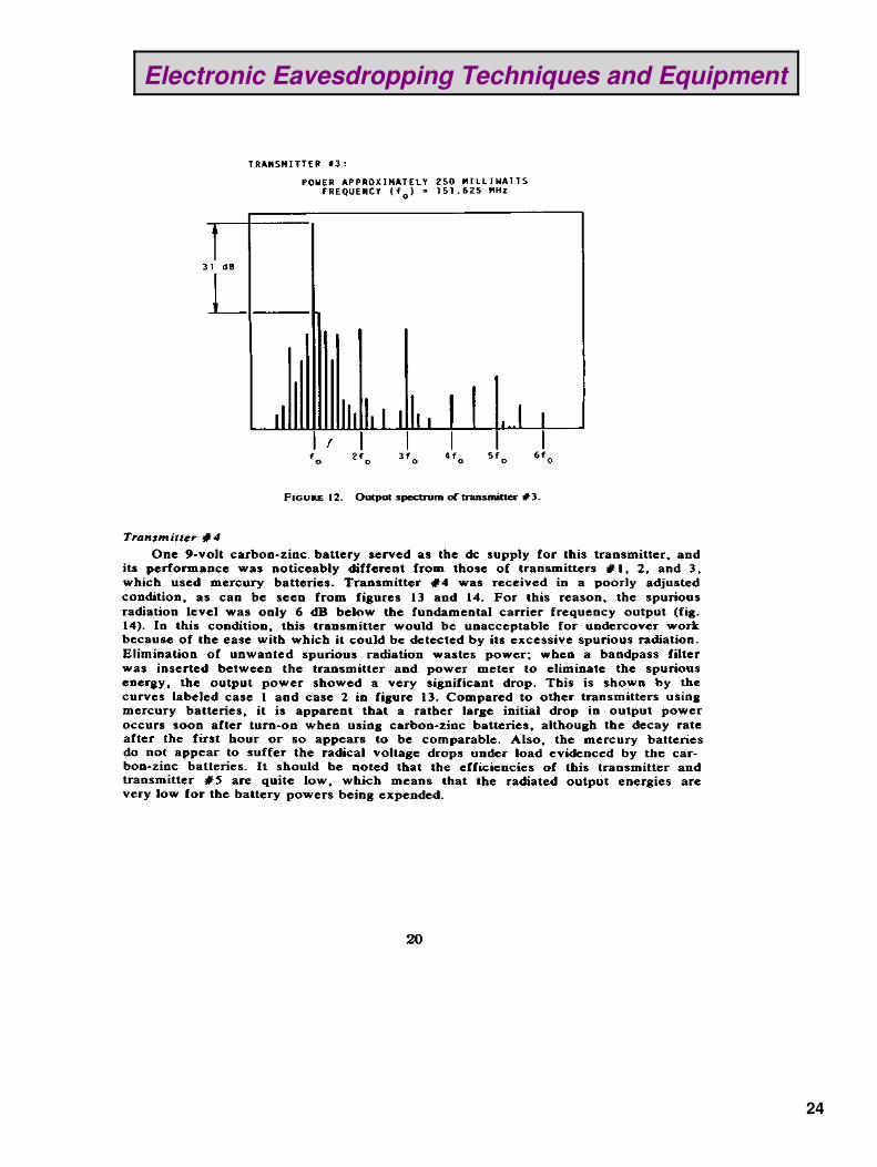
20

Electronic Eavesdropping Techniques and Equipment
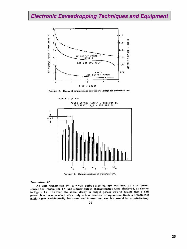
21

Electronic Eavesdropping Techniques and Equipment
22
Electronic Eavesdropping Techniques and Equipment
23
Electronic Eavesdropping Techniques and Equipment
24
Electronic Eavesdropping Techniques and Equipment
25
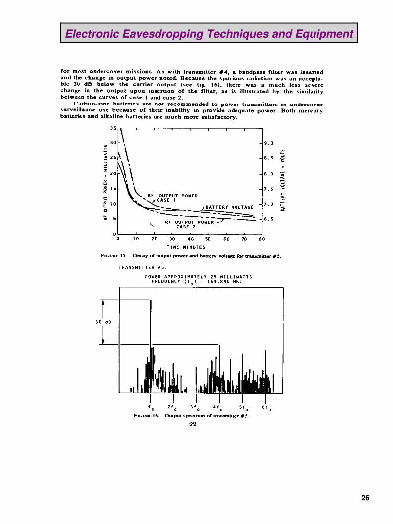
Electronic Eavesdropping Techniques and Equipment
26
Electronic Eavesdropping Techniques and Equipment
27

Electronic Eavesdropping Techniques and Equipment
28

Electronic Eavesdropping Techniques and Equipment
29

Electronic Eavesdropping Techniques and Equipment
30

Electronic Eavesdropping Techniques and Equipment
31

Electronic Eavesdropping Techniques and Equipment
32

Electronic Eavesdropping Techniques and Equipment
33
Electronic Eavesdropping Techniques and Equipment
34

Electronic Eavesdropping Techniques and Equipment
35
Electronic Eavesdropping Techniques and Equipment
36

Electronic Eavesdropping Techniques and Equipment
37
Electronic Eavesdropping Techniques and Equipment
38
Electronic Eavesdropping Techniques and Equipment
39

Electronic Eavesdropping Techniques and Equipment
40
Electronic Eavesdropping Techniques and Equipment
41

Electronic Eavesdropping Techniques and Equipment
42

Nortel DMS−100 Office Parameters Overview
Introduction
Office parameters are initially set by Northern Telecom (Nortel) to meet end−of−design criteria andswitch configuration. This overview is intended to assist operating company personnel responsiblefor administering office parameters by providing guidelines to using the available tools.
Office parameters examined in this document are located in table OFCENG (OfficeEngineering). These parameters allocate resources (memory) for switch activities such as callthroughput and custom calling usage. These parameters are initially calculated using operatingcompany input, high day/end−of−design criteria, and standard engineering formulas. The formulasare designed for standardization and simplified operating company and Nortel use. The formulasare constructed to cover a wide variety of applications and are considered set up for end−of−designfor most applications.
An ongoing process should take place to determine if parameter settings are appropriate for eachoffice's requirements. This process should include the monitoring of actual parameter usagecompared to the parameter setting in the switch. Offices may have to adjust individual parametersettings to match the changing office requirements.
Offices not at the end−of−design could reclaim memory for a period of time by reducing officeparameter settings. Caution should be used in lowering office parameters to prevent impact toswitch operation during high−day operation. Some parameters are not recommended for valuereduction. See the section "Office Parameters that are Not Recommended to be Modified".
Memory allocated for office parameters can be reclaimed during the software delivery by way ofdump and restore if the decision is made to lower office parameters. However, office parameterchanges should be safely and systematically implemented before a dump and restore.
What to Collect
The following data should be collected to determine the usage of many of the office parameters intable OFCENG:
Operational Measurement groups CP2, EXT, and FTRQ.• DMSMON report.• Listing of table OFCENG.•
Operational Measurements
The Operational Measurements (OM) and especially the high watermark OMs can be used as abench mark of the levels of traffic−dependent activity in the switch during the current interval. Thehigh watermark OMs display the highest level of simultaneous usage reached in critical officeparameters for the collection period. Overflow OMs display the number of times that the parameterwas required but no resources were available.
The following OM groups should be monitored:
CP2• EXT• FTRQ•
43
CP2 measures Call Processing software resources such as call processing letters, call condenseblocks, and wakeup blocks. EXT measures Extension Block usage such as special billing records,data extensions for operator services, and custom calling features. FTRQ measures FeatureQueuing Resources for Meridian Digital Centrex (MDC) features such as call hold, last numberredial, and call waiting. Refer to the Operational Measurements Reference Manual for informationon the registers and corresponding office parameters measured.
An OM accumulating class made up of CP2, EXT, and FTRQ should be defined with the samecollection period as office parameter OMXFR in table OFCENG. When datafilling tables OMACCand OMPRT, field WHEN set to AUTO guarantees this. The collection period and transfer periodshould be the same to ensure that the high watermark registers present a valid picture of peakactivities. With a 1−hour collection period and a 30−minute transfer period, the peak levels aresummed.
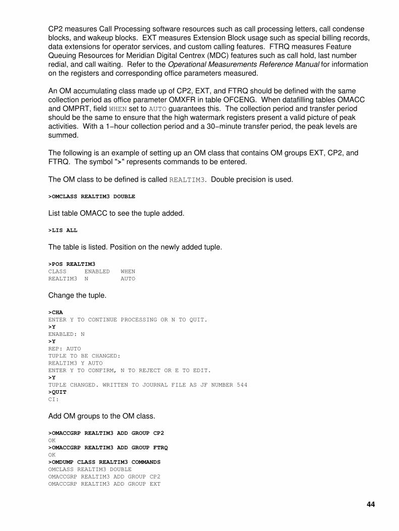
The following is an example of setting up an OM class that contains OM groups EXT, CP2, andFTRQ. The symbol ">" represents commands to be entered.
The OM class to be defined is called REALTIM3. Double precision is used.
>OMCLASS REALTIM3 DOUBLE
List table OMACC to see the tuple added.
>LIS ALL
The table is listed. Position on the newly added tuple.
>POS REALTIM3CLASS ENABLED WHEN REALTIM3 N AUTO
Change the tuple.
>CHAENTER Y TO CONTINUE PROCESSING OR N TO QUIT.>YENABLED: N>YREP: AUTOTUPLE TO BE CHANGED:REALTIM3 Y AUTOENTER Y TO CONFIRM, N TO REJECT OR E TO EDIT.>YTUPLE CHANGED. WRITTEN TO JOURNAL FILE AS JF NUMBER 544>QUITCI:
Add OM groups to the OM class.
>OMACCGRP REALTIM3 ADD GROUP CP2OK>OMACCGRP REALTIM3 ADD GROUP FTRQOK>OMDUMP CLASS REALTIM3 COMMANDSOMCLASS REALTIM3 DOUBLE OMACCGRP REALTIM3 ADD GROUP CP2 OMACCGRP REALTIM3 ADD GROUP EXT
44

OMACCGRP REALTIM3 ADD GROUP FTRQ>TABLE OMPRTTABLE: OMPRT>LIS ALL
Table OMPRT is listed. Position on an unused position. Position 228 is chosen in this example.
>POS 228
Change the tuple.
>CHAENTER Y TO CONTINUE PROCESSING OR N TO QUIT>YACTIVE: N>YSUPZERO: N>ID: ALL>ALLCLASSCLASS:>REALTIM3REP: MONTHLY>AUTOBUFFOUT: N>OUTDEV: SINK>TUPLE TO BE CHANGED:228 Y N ALLCLASS REALTIM3AUTO N SINKENTER Y TO CONFIRM. N TO REJECT OR E TO EDIT.>YTUPLE CHANGEDWRITTEN TO JOURNAL FILE AS JF NUMBER 547>QUITCI:>LOGUTILLOGUTIL:>ADDREP TATSPRT OMPR 228 Note: TATSPRT is a local printer defined for this example.1 report(s) Added>LISTROUTE DEVICE TATSPRTDevice TATSPRT print classes:ADD REPORTS:OMPR 228 (OM REPORT)DELETE REPORTS:>STARTDEV TATSPRTLog device TATSPRT has been started.Number of devices started : 1>STOPDEV TATSPRTLog device TATSPRT has been stopped.Number of devices stopped : 1
DMSMON
DMSMON is used to gather switch data as well as high watermark OMs. The switch data can beused in calculating office parameters in place of the engineering estimates used at initial load time.
DMSMON uses OM results as inputs for the DMSMON high watermark report. DMSMON itselfkeeps a running tab of a subset of parameter high watermarks over a 30−day period. For theparameters that are currently reported by DMSMON, this report is the easiest for the administrator
45

to use. However, since all the high watermark OMs are not included in DMSMON, the OM groupsmentioned previously should be collected. Also, parameter overflows are not reported in DMSMONoutput, only in the OM groups.
The following command produces the needed DMSMON information from the CI level of the MAPdisplay:
>DMSMON>HIGHPARMS
The following DMSMON example shows a subset of actual counts of switch data and highwatermarks for office parameters:
−−−−−−−−−−−−−−−−−−−−−−−−−−−−−−−−−−−−−−−−−−−−−−−−−−−−−−−−−−−−−−−−−−−−−−−−−−−−−−−−−−−−−−−−−Number of nodes: 379Number of networks: 0
Number of TM8 PMs: Insv: 3 Comm : 0Number of MTM PMs: Insv: 53 Comm: 0Number of LGC PMs: Insv: 12 Comm : 0Number of LCM PMs: Insv: 48 Comm : 0Number of DTC PMs: Insv: 13 Comm : 0Number of DP_POTS lines: 3 Number of DGT_POTS lines: 15 Number of DP_IBN lines: 185 Number of DGT_IBN lines: 2835 Number of TOTAL_UNEQ lines: 15962 Number of TOTAL_OFFL lines: 5373 Number of PPHONE_STATION lines: 152
Number of DISPLAY_PPHONE_STATION lines: 35 Number of M3009_STATION lines: 6705
Number of M5112_STATION lines: 618 Number of M5209_STATION lines: 144 Number of M5312_STATION lines: 37 Number of DNs on keysets: 35403 Number of IBN lines with CALL WAITING FEATURE: 8Number of IBN lines with CALL FORWARDING FEATURES: 508 Number of IBN lines with SPEED CALL FEATURE: 225 Number of KSET lines with CALL WAITING FEATURE: 4 Number of KSET lines with CALL FORWARDING FEATURE: 6613 Number of KSET lines with SPEED CALL FEATURE: 6327 Number of trunks: 4704 Number of unequipped trunks: 10655 Number of offline trunks: 554 Number of trunk groups: 715 Number of IBNTI trunks: 893 Number of IBNTO trunks: 334Number of IBNT2 trunks: 49 Number of OP trunks: 52 Number of RCVRMF receivers: 8 Number of RCVRDGT receivers: 4 (expected:8) *****
Number of RCVRATD receivers: 32 Number of CF3 ports: 70 Number of CF6 ports: 83 Number of LTUs: 6 Number of TTUs: 5 Number of VDUs: 39
Number of customer groups: 253
46
Number of consoleless customer groups: 250 Number of customer subgroups: 2 Number of attendant consoles: 30−−−−−−−−−−−−−−−−−−−−−−−−−−−−−−−−−−−−−−−−−−−−−−−−−−−−−−−−−−−−−−−−−−−−−−−−−−−−−−−−−−−−−−−−−
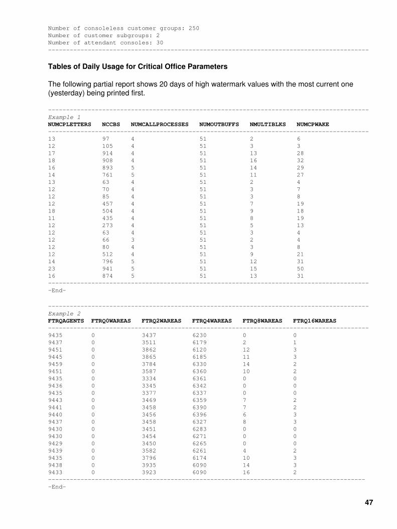
Tables of Daily Usage for Critical Office Parameters
The following partial report shows 20 days of high watermark values with the most current one(yesterday) being printed first.
−−−−−−−−−−−−−−−−−−−−−−−−−−−−−−−−−−−−−−−−−−−−−−−−−−−−−−−−−−−−−−−−−−−−−−−−−−−−−−−−−−−−−−−−−Example 1NUMCPLETTERS NCCBS NUMCALLPROCESSES NUMOUTBUFFS NMULTIBLKS NUMCPWAKE−−−−−−−−−−−−−−−−−−−−−−−−−−−−−−−−−−−−−−−−−−−−−−−−−−−−−−−−−−−−−−−−−−−−−−−−−−−−−−−−−−−−−−−−−13 97 4 51 2 612 105 4 51 3 317 914 4 51 13 2818 908 4 51 16 3216 893 5 51 14 2914 761 5 51 11 2713 63 4 51 2 412 70 4 51 3 712 85 4 51 3 812 457 4 51 7 1918 504 4 51 9 1811 435 4 51 8 1912 273 4 51 5 1312 63 4 51 3 412 66 3 51 2 412 80 4 51 3 812 512 4 51 9 2114 796 5 51 12 3123 941 5 51 15 5016 874 5 51 13 31−−−−−−−−−−−−−−−−−−−−−−−−−−−−−−−−−−−−−−−−−−−−−−−−−−−−−−−−−−−−−−−−−−−−−−−−−−−−−−−−−−−−−−−−−−End−
−−−−−−−−−−−−−−−−−−−−−−−−−−−−−−−−−−−−−−−−−−−−−−−−−−−−−−−−−−−−−−−−−−−−−−−−−−−−−−−−−−−−−−−−−Example 2FTRQAGENTS FTRQ0WAREAS FTRQ2WAREAS FTRQ4WAREAS FTRQ8WAREAS FTRQ16WAREAS−−−−−−−−−−−−−−−−−−−−−−−−−−−−−−−−−−−−−−−−−−−−−−−−−−−−−−−−−−−−−−−−−−−−−−−−−−−−−−−−−−−−−−−−−9435 0 3437 6230 0 09437 0 3511 6179 2 19451 0 3862 6120 12 39445 0 3865 6185 11 39459 0 3784 6330 14 29451 0 3587 6360 10 29435 0 3334 6361 0 09436 0 3345 6342 0 09435 0 3377 6337 0 09443 0 3469 6359 7 29441 0 3458 6390 7 29440 0 3456 6396 6 39437 0 3458 6327 8 39430 0 3451 6283 0 09430 0 3454 6271 0 09429 0 3450 6265 0 09439 0 3582 6261 4 29435 0 3796 6174 10 39438 0 3935 6090 14 39433 0 3923 6090 16 2−−−−−−−−−−−−−−−−−−−−−−−−−−−−−−−−−−−−−−−−−−−−−−−−−−−−−−−−−−−−−−−−−−−−−−−−−−−−−−−−−−−−−−−−−End−
47
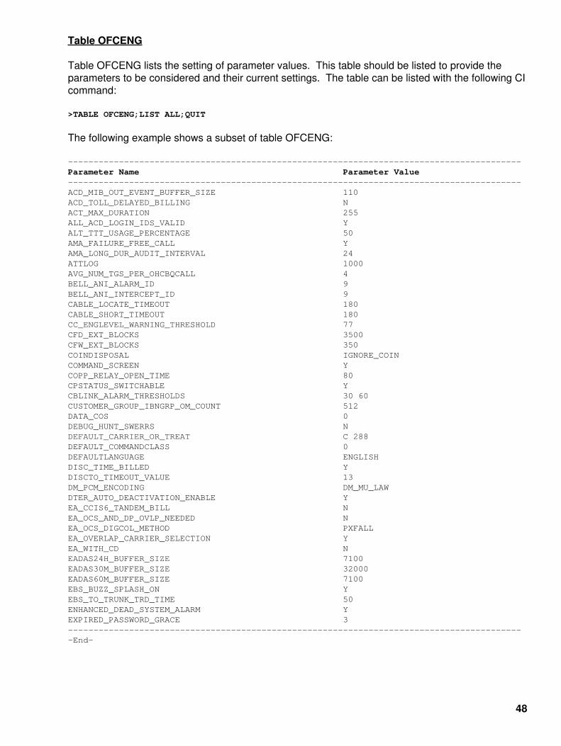
Table OFCENG
Table OFCENG lists the setting of parameter values. This table should be listed to provide theparameters to be considered and their current settings. The table can be listed with the following CIcommand:
>TABLE OFCENG;LIST ALL;QUIT
The following example shows a subset of table OFCENG:
−−−−−−−−−−−−−−−−−−−−−−−−−−−−−−−−−−−−−−−−−−−−−−−−−−−−−−−−−−−−−−−−−−−−−−−−−−−−−−−−−−−−−−−−−Parameter Name Parameter Value−−−−−−−−−−−−−−−−−−−−−−−−−−−−−−−−−−−−−−−−−−−−−−−−−−−−−−−−−−−−−−−−−−−−−−−−−−−−−−−−−−−−−−−−−ACD_MIB_OUT_EVENT_BUFFER_SIZE 110 ACD_TOLL_DELAYED_BILLING N ACT_MAX_DURATION 255 ALL_ACD_LOGIN_IDS_VALID Y ALT_TTT_USAGE_PERCENTAGE 50 AMA_FAILURE_FREE_CALL Y AMA_LONG_DUR_AUDIT_INTERVAL 24 ATTLOG 1000 AVG_NUM_TGS_PER_OHCBQCALL 4 BELL_ANI_ALARM_ID 9 BELL_ANI_INTERCEPT_ID 9CABLE_LOCATE_TIMEOUT 180 CABLE_SHORT_TIMEOUT 180 CC_ENGLEVEL_WARNING_THRESHOLD 77 CFD_EXT_BLOCKS 3500 CFW_EXT_BLOCKS 350 COINDISPOSAL IGNORE_COIN COMMAND_SCREEN Y COPP_RELAY_OPEN_TIME 80 CPSTATUS_SWITCHABLE Y CBLINK_ALARM_THRESHOLDS 30 60 CUSTOMER_GROUP_IBNGRP_OM_COUNT 512DATA_COS 0 DEBUG_HUNT_SWERRS N DEFAULT_CARRIER_OR_TREAT C 288 DEFAULT_COMMANDCLASS 0 DEFAULTLANGUAGE ENGLISH DISC_TIME_BILLED Y DISCTO_TIMEOUT_VALUE 13 DM_PCM_ENCODING DM_MU_LAW DTER_AUTO_DEACTIVATION_ENABLE YEA_CCIS6_TANDEM_BILL N EA_OCS_AND_DP_OVLP_NEEDED N EA_OCS_DIGCOL_METHOD PXFALL EA_OVERLAP_CARRIER_SELECTION Y EA_WITH_CD N EADAS24H_BUFFER_SIZE 7100EADAS30M_BUFFER_SIZE 32000 EADAS60M_BUFFER_SIZE 7100 EBS_BUZZ_SPLASH_ON Y EBS_TO_TRUNK_TRD_TIME 50 ENHANCED_DEAD_SYSTEM_ALARM Y EXPIRED_PASSWORD_GRACE 3−−−−−−−−−−−−−−−−−−−−−−−−−−−−−−−−−−−−−−−−−−−−−−−−−−−−−−−−−−−−−−−−−−−−−−−−−−−−−−−−−−−−−−−−−−End−
48

How to Interpret What is Collected
The OMs provide an indication of overflows. If there are insufficient resources for a given officeparameter, the OMs indicate this with an overflow peg. Parameter usage should be monitored in alloffices, not only those interested in reducing office parameters for the purpose of memoryreclamation.
When examining registers FTRQHI and FTRQSEIZ of OM group FTRQ and the FTRQ entities inDMSMON HIGHWATER, it should be noted that these parameters reflect the number of blockssimultaneously in use. The corresponding FTRQ office parameters reflect the number of blocksallocated in multiples of 10. For example, a setting of 300 for office parameter FTRQAGENTSallows for a FTRQAGENTS high watermark of 3,000. This multiple of 10 factor applies only toFTRQ parameters (that is, FTRQAGENTS, FTRQAUDIT, FTRQ0WAREAS, FTRQ2WAREAS,FTRQ4WAREAS, FTRQ8WAREAS, FTRQ16AREAS, FTRQ32WAREAS, FTRQ0WPERMS,FTRQ2WPERMS, FTRQ4WPERMS, FTRQ8WPERMS, FTRQ16PERMS, and FTRQ32PERMS).
The following example shows that FTRQAGENTS is set to 1261 in table OFCENG. This settingallocates 12,610 FTRQAGENT blocks as indicated in field FTRQOM_INFO in the OM groupFTRQ. For the sample period, the high watermark, field FTRQHI, indicates a maximum of 6,137feature queue blocks in simultaneous use.
CI:>TABLE OFCENG : POS FTRQAGENTSTABLE: OFCENGFTRQAGENTS 1261>LIS 10PARMNAME PARMVALFTRQAGENTS 1261FTRQAUDIT 10FTRQOWAREAS 1FTRQ2WAREAS 1575FTRQ4WAREAS 799FTRQ8WAREAS 800FTRQ16WAREAS 1FXOGS_REMBSY_BITS A_OFF_B_OFF_HKGLOBAL_CUTOFF_ON_DISCONNECT Y 80 NGROUND_START_DELAY Y>OMSHOW FTRQ HOLDINGFTRQ CLASS: HOLDING START: 1990/01/12 14:00:00 FRI: STOP: 1990/01/12 14:15:00 SLOWSAMPLES: 9 : FASTSAMPLES: 90 :
KEY (FTRQOM_TUPLE_KEY) INFO (FTRQOM_INFO) FTRQSEIZ FTRQOVFI
FTRQHI 0 FTRQAGENTS 12610 369 0 6137
1 FTRQOWAREAS 10 0 0 0
49

2 FTRQ3WAREAS 15750 509 0 3394
3 FTRQ4WAREAS 7880 238 0 2828
4 FTRQ8WAREAS 8000 72 0 30
5 FTRQ16WAREAS 10 0 0 0
Referring to the tables in Example 1 and Example 2, the high watermarks can be interpreted. Thelast 20 days of high watermarks are displayed. For FTRQ4WAREAS, 6,396 is the highest valuedisplayed. For this office, parameter FTRQ4WAREAS in table OFCENG is set to 693. Accountingfor the factor of 10, this allows for 6,930 blocks. Operating company personnel may decide to raisethis parameter since the high water value is so close to the parameter setting.
For parameter NUMCPWAKE (number of call processing wakeups), 50 is the highest 20−dayvalue. For this office, parameter NUMCPWAKE in table OFCENG is set to 425. Assuming the highday for this event is during the sample period, the operating company may decide to lower theparameter slightly to recover memory, or leave the parameter set as is.
As can be seen in the above two cases, if the value is increased or decreased, office memory isimpacted. If a parameter value is increased and made active, more memory is allocated for thatresource from spare or not in use pool of office memory. On the other hand, if a parameter value isreduced, made active, and taken through the dump and restore process, office memory is returnedto the spare pool of memory. Complete memory reclamation cannot take place without a dump andrestore.
How Often to Collect
It is imperative that the operating company monitor the actual usage regularly to account for highday busy hour for each of the critical office parameters and changing calling traffic patterns. Eachof these factors should be taken into account to establish the time interval for examining OMs.
High day busy hour for each event must be considered. The high day busy hour for POTS featuresmay be very different than that of Meridian Digital Centrex features. Based on this criterion, usagemust be monitored based on the office parameters being analyzed. For example,CFW_EXT_BLOCKS allocate the number of simultaneous active call forwarded calls.
Traffic patterns can change dramatically over time, and therefore, the actual usage could fluctuatedramatically. Actual usage must be monitored on a regular basis to determine if trends areevolving. The decision to collect daily, weekly, or biweekly is the decision of the individual operatingcompany.
How to Make a Decision
Criteria must be chosen to decide whether to lower or raise parameter values. An operatingcompany engineer can choose criteria such as never reducing a given office parameter at all ornever reducing an office parameter below three times (or more) the highest ever high watermark.
50
Lowering office parameter values should be carefully considered. In general, Nortel does notrecommend lowering office parameter values unless office memory is in jeopardy.
Factors such as planned large office additions and office history play an important role in decidinghow large a buffer to add to the office data. The operating company is responsible for determininghowlarge to make the buffer above the high watermark OMs. It is strongly recommended that theoffice be monitored for many months before making a decision.
Most operating companies will probably decide never to reduce office parameter values, unlessoffice memory is exhausted.
Office Parameters that are Not Recommended to be Modified
In general, the memory−allocating office parameter values in table OFCENG can be considered forlowering. However, Nortel does not recommend changes to the following parameters. Anychanges are made at the operating company's discretion.
NCCBS defines the number of Call Condense Blocks (CCB) required that are held up through the life of acall. NCCBS is provisioned to provide for 100% use of network facilities. No change is recommended.
•
NUMCALLPROCESSES defines the number of Call Processes (CP) required that are associated with a callduring set up, take down, and feature processing. The current formula is sufficient to provide for high callingvolumes. No change is recommended.
•
NUMCPLETTERS defines the number of call processing letters required that are used to pass messagesbetween call processes and the rest of the DMS−100 switch. NUMCPLETTERS is set at 2,000 to provide foroverload protection during peak traffic periods. No change is recommended.
•
NUMTLBS defines the number of Terminal Linkage Blocks (TLB) used in the input/output system. NUMTLBS isprovisioned based on the number of hardware nodes present in the office. No change is recommended.
•
PPMBUFFS defines the number of Peripheral Process Message (PPM) buffers used for sending messages tothe peripheral modules. If PPMBUFFS is underprovisioned, switch degradations can occur. A margin of safetyis built in to prevent degradation during high−traffic periods and unexpected high maintenance situations. Nochange is recommended.
•
Reducing Office Parameter Values
The preferred method of implementing office parameter reductions is to gradually make changes inthe existing office parameter tables, performing the necessary restarts as required during verylow−traffic times. Changing two or so parameter values downward at a time, then verifying that thechanges had no adverse effect is the safest way to implement reductions. Possible problemvariables are kept to a minimum and a known safe fallback is available. If troubles do arise,reverting back to the old values can be done quickly. The OMs should be monitored closely toensure proper engineering. All changes should be made at least three weeks prior to the dump andrestore or One Night Process (ONP). At least three weeks is required to allow the software deliveryprocess to capture the new values.
Memory is not reclaimed until the dump and restore is performed. At that time, the reduced valuesare copied from the existing load into the new office load.
If parameter reductions are required, the operating company should communicate their intentionsand work with the Nortel regional software systems engineering manager.
51

Increasing Office Parameter Values
Increasing parameter values is a safer process than reducing them. The major issue withincreasing parameter values (other than timing related parameters) is the increased memoryrequirements. Unlike reducing parameter values, memory is utilized immediately upon activation(usually a cold restart). Often, parameters in table OFCENG require more memory whenincreased. The memory requirements for parameters are in the data store area for NT40 loads, butin total office memory for SuperNode loads, where there is no distinction between data and programstore.
A basic outline of when values should be increased follows:
Determine actual spare memory available in the switch.1.
Determine the established memory requirements indicated by the required parameter value increases.2.
Analyze and determine if the amount of increased memory does not exceed the amount of memory spare andavailable for use. Keep in mind the Nortel and individual operating company requirements for spare memoryoverheads. Reference "SEB 88−01−002" or contact a Nortel regional software systems engineering manager toaid in this task. After a determination has been made that the increased values will not exceed memorylimitations including spare or overhead requirements, a safe implementation process can begin.
3.
If only two or three parameter values are to be increased, all could be done at the same time, with the monitoringof parameters and memory after the change. If larger numbers of parameters values need to be increased, astaged increase should be implemented. Monitor two or three parameter changes and if all is well and memoryusage is safe, move forward with others.
4.
Notifying Nortel
To ensure propagation to future software releases of decreases made to office parameters, theoperating company must contact their regional software systems engineering manager with a singlepoint of contact at the operating company. The contact should be able to approve of any changesto the office parameters for a given office.
Nortel engineers office parameters based on operating company input and standard formulas. Awide variety of applications are covered by the standard formulas. These formulas yield a safevalue in nearly every office. The operating company should monitor the office parameter usage onan ongoing basis to determine if the parameter settings are appropriate for the office application.
Any changes made to the office parameters discussed in this document result in a change in thememory allocated in the switch. An increase in a setting requires more memory. A decrease invalue decreases memory requirements. A decrease in a parameter value only yields an actualmemory decrease if a rebuild (that is, a dump and restore) occurs.
52
Nortel DMS−100 CDN SERVORD Command
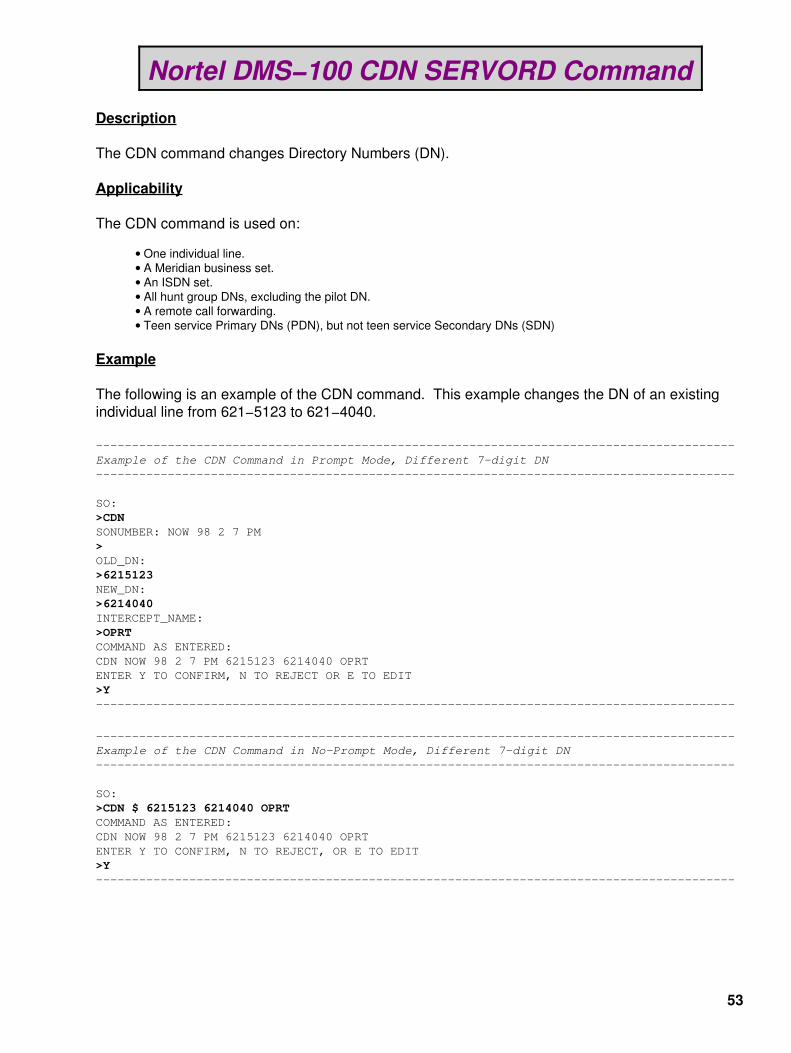
Description
The CDN command changes Directory Numbers (DN).
Applicability
The CDN command is used on:
One individual line.• A Meridian business set.• An ISDN set.• All hunt group DNs, excluding the pilot DN.• A remote call forwarding.• Teen service Primary DNs (PDN), but not teen service Secondary DNs (SDN)•
Example
The following is an example of the CDN command. This example changes the DN of an existingindividual line from 621−5123 to 621−4040.
−−−−−−−−−−−−−−−−−−−−−−−−−−−−−−−−−−−−−−−−−−−−−−−−−−−−−−−−−−−−−−−−−−−−−−−−−−−−−−−−−−−−−−−−−Example of the CDN Command in Prompt Mode, Different 7−digit DN−−−−−−−−−−−−−−−−−−−−−−−−−−−−−−−−−−−−−−−−−−−−−−−−−−−−−−−−−−−−−−−−−−−−−−−−−−−−−−−−−−−−−−−−−
SO:>CDNSONUMBER: NOW 98 2 7 PM>OLD_DN:>6215123NEW_DN:>6214040INTERCEPT_NAME:>OPRTCOMMAND AS ENTERED:CDN NOW 98 2 7 PM 6215123 6214040 OPRTENTER Y TO CONFIRM, N TO REJECT OR E TO EDIT>Y−−−−−−−−−−−−−−−−−−−−−−−−−−−−−−−−−−−−−−−−−−−−−−−−−−−−−−−−−−−−−−−−−−−−−−−−−−−−−−−−−−−−−−−−−
−−−−−−−−−−−−−−−−−−−−−−−−−−−−−−−−−−−−−−−−−−−−−−−−−−−−−−−−−−−−−−−−−−−−−−−−−−−−−−−−−−−−−−−−−Example of the CDN Command in No−Prompt Mode, Different 7−digit DN−−−−−−−−−−−−−−−−−−−−−−−−−−−−−−−−−−−−−−−−−−−−−−−−−−−−−−−−−−−−−−−−−−−−−−−−−−−−−−−−−−−−−−−−−
SO:>CDN $ 6215123 6214040 OPRTCOMMAND AS ENTERED:CDN NOW 98 2 7 PM 6215123 6214040 OPRTENTER Y TO CONFIRM, N TO REJECT, OR E TO EDIT>Y−−−−−−−−−−−−−−−−−−−−−−−−−−−−−−−−−−−−−−−−−−−−−−−−−−−−−−−−−−−−−−−−−−−−−−−−−−−−−−−−−−−−−−−−−
53

−−−−−−−−−−−−−−−−−−−−−−−−−−−−−−−−−−−−−−−−−−−−−−−−−−−−−−−−−−−−−−−−−−−−−−−−−−−−−−−−−−−−−−−−−Example of the CDN Command in Prompt Mode, 10−digit DN−−−−−−−−−−−−−−−−−−−−−−−−−−−−−−−−−−−−−−−−−−−−−−−−−−−−−−−−−−−−−−−−−−−−−−−−−−−−−−−−−−−−−−−−−
SO:>CDNSONUMBER: NOW 98 2 7 PM>OLD_DN:>9196215123NEW_DN:>9196214040INTERCEPT_NAME:>OPRTCOMMAND AS ENTERED:CDN NOW 98 2 7 PM 9196215123 9196214040 OPRTENTER Y TO CONFIRM, N TO REJECT, OR E TO EDIT>Y−−−−−−−−−−−−−−−−−−−−−−−−−−−−−−−−−−−−−−−−−−−−−−−−−−−−−−−−−−−−−−−−−−−−−−−−−−−−−−−−−−−−−−−−−
−−−−−−−−−−−−−−−−−−−−−−−−−−−−−−−−−−−−−−−−−−−−−−−−−−−−−−−−−−−−−−−−−−−−−−−−−−−−−−−−−−−−−−−−−Example of the CDN Command in No−Prompt Mode, 10−digit DN−−−−−−−−−−−−−−−−−−−−−−−−−−−−−−−−−−−−−−−−−−−−−−−−−−−−−−−−−−−−−−−−−−−−−−−−−−−−−−−−−−−−−−−−−
SO:>CDN $ 9196215123 9196214040 OPRTCOMMAND AS ENTERED:CDN NOW 98 2 7 PM 9196215123 9196214040 OPRTENTER Y TO CONFIRM, N TO REJECT, OR E TO EDIT >Y−−−−−−−−−−−−−−−−−−−−−−−−−−−−−−−−−−−−−−−−−−−−−−−−−−−−−−−−−−−−−−−−−−−−−−−−−−−−−−−−−−−−−−−−−
−−−−−−−−−−−−−−−−−−−−−−−−−−−−−−−−−−−−−−−−−−−−−−−−−−−−−−−−−−−−−−−−−−−−−−−−−−−−−−−−−−−−−−−−−Example of the CDN Command in Prompt Mode, Same 7−digit DNs−−−−−−−−−−−−−−−−−−−−−−−−−−−−−−−−−−−−−−−−−−−−−−−−−−−−−−−−−−−−−−−−−−−−−−−−−−−−−−−−−−−−−−−−−
SO:>CDNSONUMBER: NOW 98 2 7 PM>OLD_DN:>6215123This Local DN is not Unique.Please Use the Full National DN.6215123*** Error ***TYPE OF MEM_DN IS SO_DRPLEASE ENTEROLD_DN:>9196215123NEW_DN:>9196214040INTERCEPT_NAME:>OPRTCOMMAND AS ENTERED:CDN NOW 98 2 7 PM 9196215123 9196214040 OPRTENTER Y TO CONFIRM, N TO REJECT, OR E TO EDIT >Y−−−−−−−−−−−−−−−−−−−−−−−−−−−−−−−−−−−−−−−−−−−−−−−−−−−−−−−−−−−−−−−−−−−−−−−−−−−−−−−−−−−−−−−−−
Prompts
The system prompts for the CDN command are shown in the following table:
54

−−−−−−−−−−−−−−−−−−−−−−−−−−−−−−−−−−−−−−−−−−−−−−−−−−−−−−−−−−−−−−−−−−−−−−−−−−−−−−−−−−−−−−−−−Input Prompts for the CDN Command
Prompt Valid input Explanation−−−−−−−−−−−−−−−−−−−−−−−−−−−−−−−−−−−−−−−−−−−−−−−−−−−−−−−−−−−−−−−−−−−−−−−−−−−−−−−−−−−−−−−−−SONUMBER An entry in the format: The unique number of the service order to be entered. abnnnnnc yy mm dd {AM} {PM} Date the service order is to Where: be processed.
* a = Obligatory Alphabetical Character (A−Z)
* b = Optional Alphabetical Character (A−Z)
* nnnnn = 5 Obligatory Numerical Characters
* c = Optional Alphabetical Character (A−Z)
* yy = Year (00−99)
* mm = Month (1−12)
* dd = Day (1−31)−−−−−−−−−−−−−−−−−−−−−−−−−−−−−−−−−−−−−−−−−−−−−−−−−−−−−−−−−−−−−−−−−−−−−−−−−−−−−−−−−−−−−−−−− OLD_DN Seven or ten digits. Enter the DN being replaced by a new DN Refer to the "Notes" section in a CDN service order. that follows this table for information on mandatory 10−digit input. −−−−−−−−−−−−−−−−−−−−−−−−−−−−−−−−−−−−−−−−−−−−−−−−−−−−−−−−−−−−−−−−−−−−−−−−−−−−−−−−−−−−−−−−−NEW_DN Seven or ten digits. Enter the new DN that replaces the Refer to the "Notes" section previous DN. that follows this table for information on mandatory 10−digit input. −−−−−−−−−−−−−−−−−−−−−−−−−−−−−−−−−−−−−−−−−−−−−−−−−−−−−−−−−−−−−−−−−−−−−−−−−−−−−−−−−−−−−−−−−INTERCEPT_ AINT = Attendant Intercept Enter the type of intercept.NAME (IBN lines only) If the DN is unknown, enter BLDN. Office parameter SO_CICP_OFRT_ICP_ALLOWED ANCT = Machine Intercept in table OFCOPT lets you toggle between OPRT and BLDN intercepts. BLDN = Blank DN Refer to the "Notes" section that follows this table. PODN is an line portability CANN = Customer Announcement treatment that designates a ported−out DN. (IBN lines only)
OPRT = Operator Intercept
PODN = Ported−Out DN
UNDN = Undefined DN−−−−−−−−−−−−−−−−−−−−−−−−−−−−−−−−−−−−−−−−−−−−−−−−−−−−−−−−−−−−−−−−−−−−−−−−−−−−−−−−−−−−−−−−−−End−
55

Notes
The following notes apply to the CDN command:
Use the CDN command to change the DN of a Directory Number Hunt (DNH) group member.•
The CDN command cannot change the pilot number of a hunt group. To change the pilot of a hunt group,remove the hunt group with the DEL and OUT commands.
•
The CDN command:•
Does not add options.♦ Does not delete options.♦ Does not change a Line Equipment Number (LEN).♦ Does not change a Line Class Code (LCC).♦ Does not change a Line Treatment Group (LTG).♦ Does not change the ringing code.♦
The last seven digits of the new DN must not be the same as the last seven digits of the old DN. The systemgenerates an error message if the DN digits are the same.
•
If the operating company enters a seven−digit DN and the office code exists in multiple Service NumberingPlanning Areas (SNPA − area codes), the system displays an error message. A reprompt occurs.
•
With NA010 and up, the CDN command is no longer blocked by SERVORD for MADN CACH. KSETLINE tablecontrol performs the changes for a MADN CACH group and the underlying data for all members of the CACHgroup.
•
56
Spread Spectrum Surveillance Bug
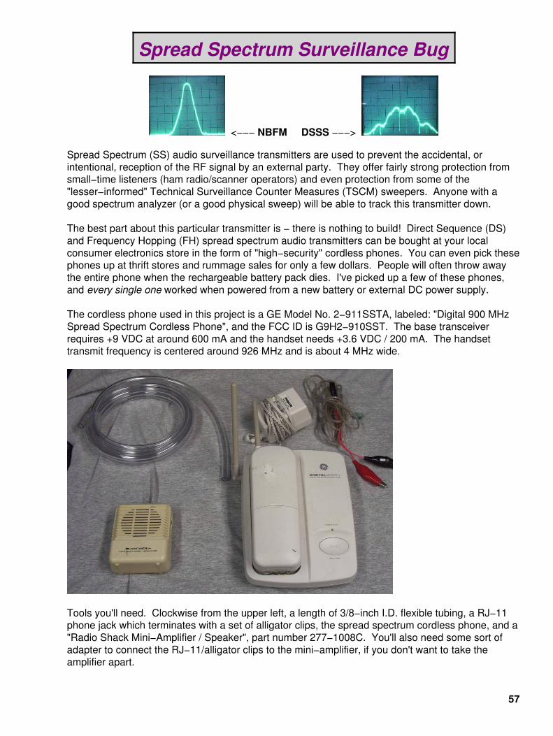
<−−− NBFM DSSS −−−>
Spread Spectrum (SS) audio surveillance transmitters are used to prevent the accidental, orintentional, reception of the RF signal by an external party. They offer fairly strong protection fromsmall−time listeners (ham radio/scanner operators) and even protection from some of the"lesser−informed" Technical Surveillance Counter Measures (TSCM) sweepers. Anyone with agood spectrum analyzer (or a good physical sweep) will be able to track this transmitter down.
The best part about this particular transmitter is − there is nothing to build! Direct Sequence (DS)and Frequency Hopping (FH) spread spectrum audio transmitters can be bought at your localconsumer electronics store in the form of "high−security" cordless phones. You can even pick thesephones up at thrift stores and rummage sales for only a few dollars. People will often throw awaythe entire phone when the rechargeable battery pack dies. I've picked up a few of these phones,and every single one worked when powered from a new battery or external DC power supply.
The cordless phone used in this project is a GE Model No. 2−911SSTA, labeled: "Digital 900 MHzSpread Spectrum Cordless Phone", and the FCC ID is G9H2−910SST. The base transceiverrequires +9 VDC at around 600 mA and the handset needs +3.6 VDC / 200 mA. The handsettransmit frequency is centered around 926 MHz and is about 4 MHz wide.
Tools you'll need. Clockwise from the upper left, a length of 3/8−inch I.D. flexible tubing, a RJ−11phone jack which terminates with a set of alligator clips, the spread spectrum cordless phone, and a"Radio Shack Mini−Amplifier / Speaker", part number 277−1008C. You'll also need some sort ofadapter to connect the RJ−11/alligator clips to the mini−amplifier, if you don't want to take theamplifier apart.
57
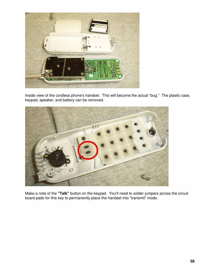
Inside view of the cordless phone's handset. This will become the actual "bug." The plastic case,keypad, speaker, and battery can be removed.
Make a note of the "Talk" button on the keypad. You'll need to solder jumpers across the circuitboard pads for this key to permanently place the handset into "transmit" mode.
58

Closeup internal view of the handset. The antenna/RF section is on the left. The RED circleindicates the POSITIVE (+3.6 VDC) connection for the battery, the BLUE circle indicates theNEGATIVE or GROUND connection for the battery. The BLACK circle is the solder connection forthe handset's internal electret microphone. You may want to replace the phone's original electretmic with one that has better sensivitity and signal−to−noise ratio, but that's optional.
Also, some cordless phones utilize "noise−cancelling" microphones. These should be replaced asthey don't offer the best sensitivity for surveillance purposes.
Alternate view of the above connections.
59
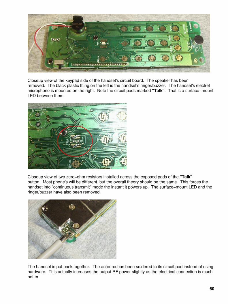
Closeup view of the keypad side of the handset's circuit board. The speaker has beenremoved. The black plastic thing on the left is the handset's ringer/buzzer. The handset's electretmicrophone is mounted on the right. Note the circuit pads marked "Talk". That is a surface−mountLED between them.
Closeup view of two zero−ohm resistors installed across the exposed pads of the "Talk"button. Most phone's will be different, but the overall theory should be the same. This forces thehandset into "continuous transmit" mode the instant it powers up. The surface−mount LED and theringer/buzzer have also been removed.
The handset is put back together. The antenna has been soldered to its circuit pad instead of usinghardware. This actually increases the output RF power slightly as the electrical connection is muchbetter.
60

The completed surveillance bug. The DC power supply comes from four "AAA"−size batteries. Youshould use NiCad rechargeable batteries as these only output 1.2 Volts each (+4.8 VDC total). Theuse of regular alkaline batteries will require the use of some type of voltage regulator to reduce theinput voltage to under +5 Volts.
As soon as the batteries are put in, this bug will start transmitting. Be sure the cordless phone basestation is powered and ready (and in radio line−of−sight) so the handset can "sync" its signal,otherwise the handset will require a complete power−down (removal of the batteries), and this couldbe difficult in covert operations.
This is what the tubing is used for. When you don't want, or can't, extend the wires of the electretmicrophone, just place a piece of tubing over the mic and run the tubing to the location which needsto be monitored. The tubing can be run a considerable distance with no degradation of audioquality. Be careful not to break the microphone leads though.
Placing your transmitter/microphone at the end of a length of tubing is also a good way to defeatsome metal detectors and non−linear junction detectors during a TSCM sweep.
61
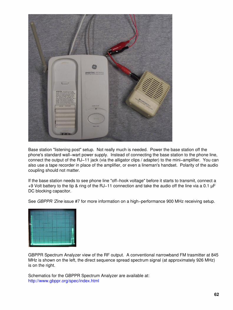
Base station "listening post" setup. Not really much is needed. Power the base station off thephone's standard wall−wart power supply. Instead of connecting the base station to the phone line,connect the output of the RJ−11 jack (via the alligator clips / adapter) to the mini−amplifier. You canalso use a tape recorder in place of the amplifier, or even a lineman's handset. Polarity of the audiocoupling should not matter.
If the base station needs to see phone line "off−hook voltage" before it starts to transmit, connect a+9 Volt battery to the tip & ring of the RJ−11 connection and take the audio off the line via a 0.1 µFDC blocking capacitor.
See GBPPR 'Zine issue #7 for more information on a high−performance 900 MHz receiving setup.
GBPPR Spectrum Analyzer view of the RF output. A conventional narrowband FM trasmitter at 845MHz is shown on the left, the direct sequence spread spectrum signal (at approximately 926 MHz)is on the right.
Schematics for the GBPPR Spectrum Analyzer are available at:http://www.gbppr.org/spec/index.html
62

Notes
The following was from a post on the "TSCM−L" list maintaind by James M. Atkinson:http://www.tscm.com
To: TSCM−[email protected]: "James M. Atkinson, Comm−Eng" <[email protected]>Subject: Spread Spectrum Update
Several weeks ago I had a chance to examine a number of spread spectrum microwave bugging devices.
Since that time I've conducted some analysis andgathered further intelligence on the circuit.
Here are a few of my observations.
======= C O N F I D E N T I A L ========
1) Most of the products use a high bandwidth QPSK/BPSKmodulator, multi channel audio CODEC, and a RISCmicro−controller chip (all components are eithersurface mounted ICs or multiple dice potted in epoxy).
2) RF Circuit seems to be a simple homodyne audiotransmitter (6 Ghz Gilbert Cell Mixer) which is drivenby a single CPU/microcontroller (with a clock speed of 180 Mhz).
3) Frequencies used for the ultra low power device areclean from 130 Mhz to 4 Ghz, circuit starts to failabove 5.5 Ghz (but is still operable to about 8 Ghz).
4) Emitter is driven directly from vector modulator chip,with no power amp circuits. PIN diode found on outputappears to provide gain control or disconnect ofcircuit, but provides no amplification of signal.
5) Noise floor of circuit is −135 dBm (below 2 ghz),−142 dBm (2−4 ghz), and −150 dBm above 4 Ghz.
6) Signal has a variable bandwidth which varies between350 Mhz and 900 Mhz. Appears to be designed for a 900 Mhz bandwidth signal. Device operates "deep" inside the noise floor.
7) Virtually impossible to detect at close range with aconventional RF spectrum analyzer (492/494/8566/etc).
8) Detectable with most wideband systems (with IF BWabove 300 − 900 Mhz, 700 Mhz ideal).
8) VCC = +3.0 VDC, all circuits functional 2.3 to 6.8 VDC
9) Output applied to PIN diode ranges between −28 and−42 dBm (depending on frequency and span)
10) Device enters some type of sleep mode when poweris present but audio level is low (seems to autosquelch). Total current draw when in sleep mode is 12µA. Device does not emit RF energy when in sleep mode.
11) One of the devices has no type of connection forexternal power, but instead uses a uses a network of
63
Schottky diodes and capacitors which constitute aneffective RF to DC converter.
12) The RF to DC circuit requires an un−modulated 10−15Ghz RF signal, and seems to respond well to X−Bandmicrowave motion detectors used for many corporatealarm systems.
13) Device also has a small microphone built onto thecircuit, microphone measures 4.5mm * 1.6mm * 4.1mm.
14) Entire device measured 3.2 cm * 5.2 cm and about 3mm thick (or about the thickness of a standardbusiness envelope).
15) Device contains some type of adhesive on bothsides of a foil backing. Suspect it's applied as some typeof "sticky label". Once the device is installed any attempt to remove results in its total destruction (unless you freeze it off).
16) The French government has been know to use a similar device in some of its "Diplomatic" activities.
−jma
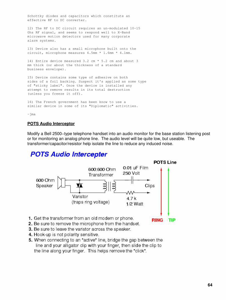
POTS Audio Interceptor
Modify a Bell 2500−type telephone handset into an audio monitor for the base station listening postor for monitoring an analog phone line. The audio level will be quite low, but useable. Thetransformer/capacitor/resistor help isolate the line to reduce any induced noise.
64
Picture of the POTS Audio Interceptor. The coupling transformer is from an old modem.
Closeup view.
65

"Shotgun" Directional Microphone
Introduction
The multitube "shotgun" directional microphone, as seen in some movies, may just be one of thebiggest hoaxes of all time. The physics which originally created it for a Popular Electronics articleback in 1964 revolved around one living in an ideal, perfect world. Many of the thousands of peoplewho ran out to build one of these microphones where often disappointed in its performance. Sorry,but simple, non−contact audio microphones can't hear through walls or intercept those whispersfrom a mile away (well, they can − but that's another story). Shotgun directional microphones onlyreduce the "receiving range" in which the microphone is pointed, they don't offer any gain! A freshset of ears will often beat many fancy directional microphone designs...
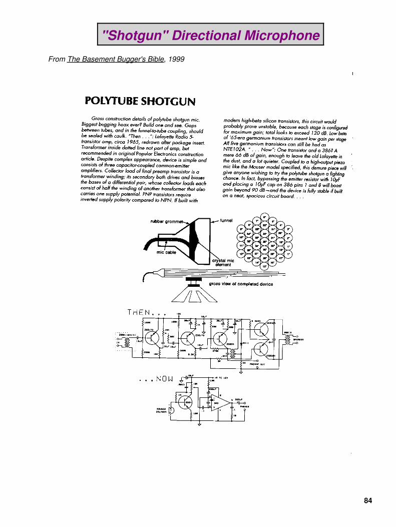
But with today's modern electrical components, it is possible to overcome some of theperformance obstacles inherent in its design. This article will be a detailed overview of theassembly and construction of a shotgun mic, and then following this article will be the scannedversion of the original 1964 Popular Electronics article. The Poptronics article goes into much moredetail on the actual hardware construction and theory, so you may wish to review that first. Alsoincluded is a scan of a page in the book The Basement Bugger's Bible, one of the best homebrewsurveillance books out there. This particular page has more info on the microphone and aschematic for a higher−performance audio amplifier than what was used in the original PopularElectronics article.
Overview
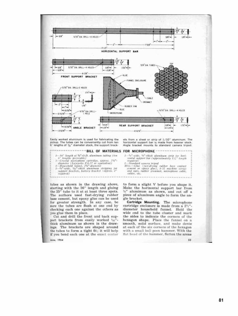
Start with about sixty feet of 1/2−inch O.D. aluminium tubing. The original article used 3/8−inchdiameter tubing, but 1/2−inch seems to be much easier to find at the hardware store. Also pick upsome two−part, fast−drying epoxy, and a good tubing cutter. Copper tubing can be used in a pinch.
66

Start cutting the tubing per the Popular Electronics article. Cut one 36−inch piece, one 35−inchpiece, one 34−inch piece, one 33−inch piece, etc. until you get down to 1−inch. You'll need two ofthose. Debur the fresh cut ends with a file and clean the tubing with steel wool and denaturedalcohol to prepare the aluminium for the epoxy.
Starting with the 36−inch piece, apply some epoxy and surround this tube with the other pieces,going down in length (i.e. 35−inch, 34−inch, etc.). The tubing must be very clean for the epoxy tostick. Aluminium will oxidize quickly after being cleaned.
67
When finished, it will look something like this. The construction doesn't make any sense at first, butit will work out, provided you cut all the pieces to the right length. Notice how it looks like three ringsaround the original 36−inch tube. Remember that it needs two 1−inch pieces to finish off the sides,also be sure the tubing ends are all properly aligned!
68

Another (somewhat) finished view. I cleaned the aluminium tubing with a little bit of lye and hotwater (DANGER! − Doing that can give you an ouchy if you have the I.Q. of a $2600 subscriber)then I spray painted it with a zinc−chromate primer. Next, I sprayed almost a whole can of blackPlasti−Dip spray−on plastic coating on the outside of the tubing. This was done to hopefully help inthe reduction of accidental noise vibration pick−up while the microphone is in operation − I think itworked a little bit.
69
View of the mounting block. It's just a scrap piece of aluminium, with a 1/4−inch (20 TPI) tappedhole, epoxied to the approximate middle of the shotgun mic. This can be used for mounting themicrophone tubes to a camera tripod.
Another overall view.
Full view of the shotgun microphone tubes.
70
These are the components which will be needed to make the "funnel" for the audio amplifier whichwill attach to the back of the microphone tubes. Clockwise from the the upper left is a PVC 3−inchto 2−inch reducing coupler, a plug−in thingy to add threads to the reducing coupler, and thematching threaded coupler for that part. Next, is some rope caulk, and finally, a high−outputpiezoelectric microphone element, Mouser (http://www.mouser.com) part number 25LM024. I'mkinda guessing at this point, so if you can think of something better for your own design, use it.
All the PVC parts are painted with a copper "flake" paint to help in the attenuation of anyelectromagnetic interference.
71
Use the rope caulk to mount the piezoelectric microphone element inside the threadedplug−in. Secure it from both the front and the back.
Alternate view of the microphone element inside the threaded plug−in.
72

Rear view of the microphone element inside the threaded plug−in. The isolated (red) pad is themicrophone's POSITIVE terminal, the other tab is CASE GROUND.
Then slide the threaded plug−in into the 3−inch to 2−inch reducing coupler. It should looksomething like the picture.
73
This is how the PVC parts should look when connected.
Audio amplifier circuit board. Test setup.
74
Closeup picture of the audio amplifier circuit board. A combination of both surface mount andleaded components are used to reduce space. The red/black leads on the left are for themicrophone element. The white/green/brown wire bundle is for the volume controlpotentiometer. The white/black leads out the bottom are for the speaker and the red/black leads areconnected to a 9 Volt battery.
Try to use 1% metal−film resistors, as they offer the lowest noise. Electrolytic capacitors should beof high quality. Digi−Key carries a good Panasonic line. Low value capacitors should be ofpolystyrene or polypropylene dielectric material. Keep the areas around the feedbackresistor/capacitor in the MAX427 clear of any solder flux.
75

Picture of the audio amplifier board mounted between the threaded PVC adapters. The PVC endcap contains the volume control potentiometer with an integrated on/off switch. The audio output isvia a 1/4−inch mono headphone jack. The end cap is taped to the other PVC pieces.
The funnel is fitted to the microphone tubes. You may have to grid the PVC reducing coupler with aDremel tool for it to fit the tubing. Then pound the coupler onto the tubes with a rubber mallet. Itshould be a tight fit. Seal the funnel with rope caulk.
76

Finished microphone. Apply a coat of olive drab paint or some other form of camouflage. It workspretty well, but don't expect any miracles. The audio is quite "tinny" due to the microphoneelement's poor bass response. Use an external equalizer to correct this. Increase the value of the10k resistor in the MAX427's feedback to increase the overall amplifier gain.
Low Noise Microphone Amplifier PCB Pattern
Etch on an approximate 2−inch diameter board. Use good FR−4 laminate. Tin, and wash awayany left over solder flux.
77

Low Noise Microphone Amplifier Schematic
78

"Shotgun" Directional Microphone
From Popular Electronics, June 1964
79
80
81

82
83
"Shotgun" Directional Microphone
From The Basement Bugger's Bible, 1999
84

Rugged J−Pole Antenna Design
Overview
The J−pole antenna is one of the most widely used antennas in amateur SIGINT/EW radio due toits low cost and ease of construction & installation. Its design dates back to the early 1940s when itwas trailed behind blimps (Zeppelins) for radio communications during the Eurosavage's annuallittle scuffle.
The antenna is called the "J−pole" because its elements are in the shape of a "J", duh. Theantenna elements consists of a main radiating 1/2−wavelength vertical element which is fed by a(non−radiating) 1/4−wavelength matching stub. It is actually designed to be fed with a balancedtransmission line (i.e. not coax), but there are tricks to overcome that. The radiation pattern is veryclose to that of a common dipole, but is skewed slightly due to interactions between the mainelement and the matching stub.
This article will cover the construction of a rugged, portable J−pole antenna that was designed tobe used with FRS radios operating in the 465 MHz band. J−pole antennas are useful & scalable forany frequency between 50 and 900 MHz. The gain of this particular style antenna will only bearound 1 dBd, based on EZNEC models. Testing shows it to give approximately the sameperformance of a 1/2−wave dipole. Contrary to what others may say, this antenna has no gainwhen constructed with only a single main radiating element. Increasing the main radiating elementto 5/8−wavelength also does not improve the antenna's performance.
Schematic / Construction
The best material for this antenna is 1/2−inch diameter rigid−wall copper pipe and fittings used forplumbing. 3/4−inch and 3/8−inch diameter pipe can be adapted when more strength or less weightis required. All the pipe and fittings must be properly fluxed and soldered for the antenna to work.
The copper pipe should be cut using a tube cutter and not a hacksaw. This will help maintain thefine dimensions required for the element lengths.
Every copper piece that is to be soldered should be rigorously cleaned with fine grit emerycloth. After cleaning the connection, apply a very thin coat of solder flux. Solder will only stick tothe copper with the solder flux. Avoid using too much flux.
Soldering the connection is the most critical step. There are two main points you should followwhen soldering copper pipe. First, avoid using too much solder. It will look messy and is reallypointless as the mechanical/electrical strength comes from the metal−on−metal connection and notthe solder. Second, avoid getting the solder connection too hot. Use a slowly rotating propanetorch to heat the entire area to be soldered. Solder will also only flow where there is heat. Toomuch heat can weaken the solder connection and copper pipe.
85

Schematic is from this excellent website: http://www.packetradio.com/JpoleCALC.htm
Pictures
Example components used in the construction of a portable J−pole. From the left, is a large airchamber. This makes a perfect mounting pole. Next, the white parts, are threaded PVCcouplers. WTF? Yes, if you isolate the J−pole antenna from the mounting pole, the antenna's
86

radiation angle will be much closer to the ground. This isolation is optional, as the PVC partssignificantly reduce the ruggedness of the antenna's construction. The rest of the components arestandard copper pipe fittings (elbow, T, end caps, threaded adapters) and a length of rigid−wallcopper pipe.
Example picture showing the components soldered together. The PVC couplers should be glued tothe copper.
Example picture showing the components of a rugged (non−isolated) J−pole. This design is moresuited for portable operations. The radiation pattern has a higher "take off" angle, but the antennawill still perform flawlessly in almost all situations.
The removable main radiating element should only be used for low frequency (VHF) antennas. AtUHF and higher, it will harm the antenna's performance − and it's not really needed as the elementlengths are not too long.
87
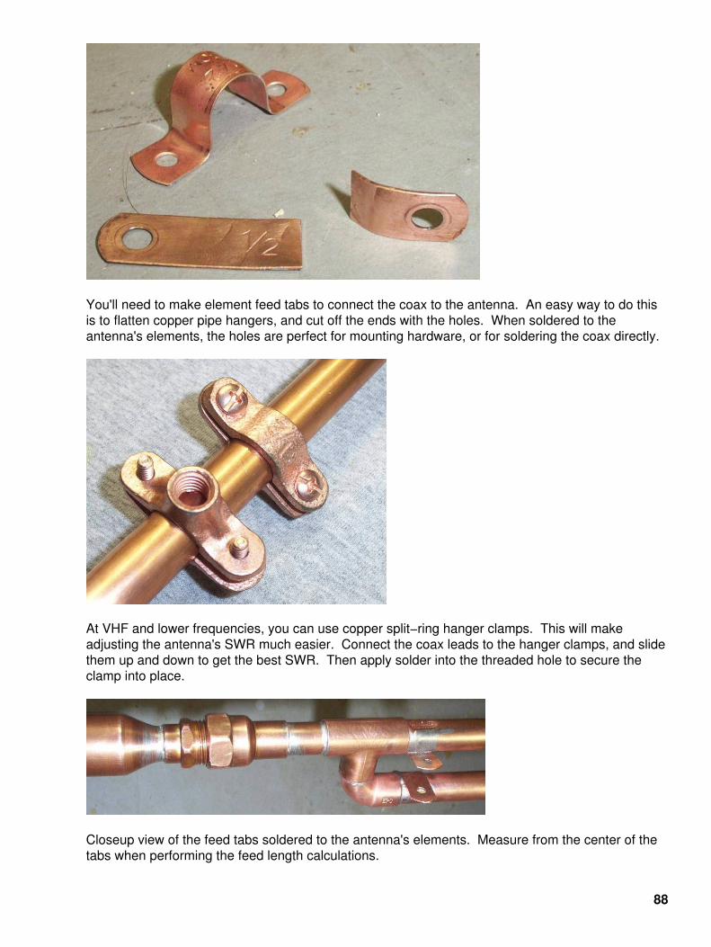
You'll need to make element feed tabs to connect the coax to the antenna. An easy way to do thisis to flatten copper pipe hangers, and cut off the ends with the holes. When soldered to theantenna's elements, the holes are perfect for mounting hardware, or for soldering the coax directly.
At VHF and lower frequencies, you can use copper split−ring hanger clamps. This will makeadjusting the antenna's SWR much easier. Connect the coax leads to the hanger clamps, and slidethem up and down to get the best SWR. Then apply solder into the threaded hole to secure theclamp into place.
Closeup view of the feed tabs soldered to the antenna's elements. Measure from the center of thetabs when performing the feed length calculations.
88
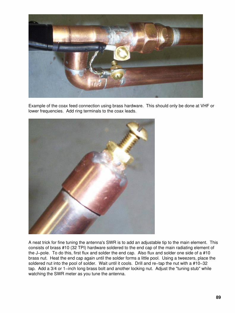
Example of the coax feed connection using brass hardware. This should only be done at VHF orlower frequencies. Add ring terminals to the coax leads.
A neat trick for fine tuning the antenna's SWR is to add an adjustable tip to the main element. Thisconsists of brass #10 (32 TPI) hardware soldered to the end cap of the main radiating element ofthe J−pole. To do this, first flux and solder the end cap. Also flux and solder one side of a #10brass nut. Heat the end cap again until the solder forms a little pool. Using a tweezers, place thesoldered nut into the pool of solder. Wait until it cools. Drill and re−tap the nut with a #10−32tap. Add a 3/4 or 1−inch long brass bolt and another locking nut. Adjust the "tuning stub" whilewatching the SWR meter as you tune the antenna.
89
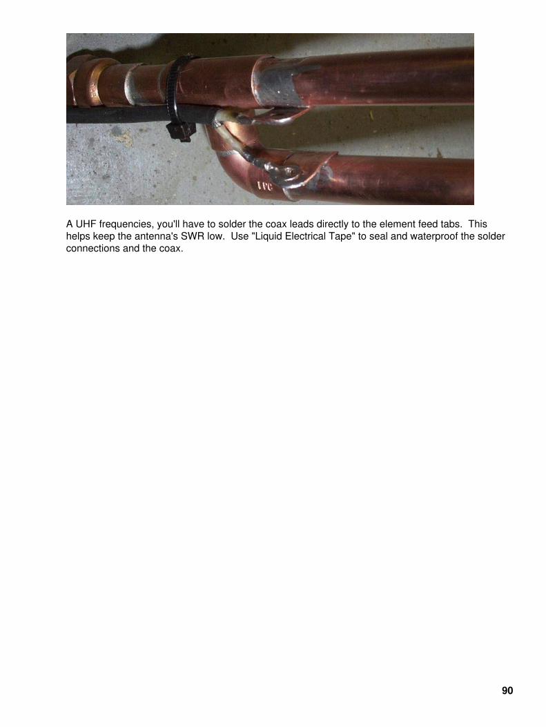
A UHF frequencies, you'll have to solder the coax leads directly to the element feed tabs. Thishelps keep the antenna's SWR low. Use "Liquid Electrical Tape" to seal and waterproof the solderconnections and the coax.
90

Finished J−pole antenna at the test range. It has a 15 dB return loss (or SWR under 2:1) across theentire FRS band. Note the coil of coax forming a decoupling loop below the antenna's feed. Thishelps prevent RF from flowing on the outside of the coax and distorting the antenna's radiationpattern. This is an important step. Just loop about four or five turns of coax tightly right before theantenna feed.
91

Bonus
92

End of Issue #16
Any Questions?
Editorial and Rants
The idea behind "African Aid" is to take money from poor people in rich countries and give it to richpeople in poor countries.
Don't worry, those rich college professors and leftists thugs just love Marxist dictators.
93

Maybe if we all got together to hold hands and sing songs it will stop those bulldozers.
Where are those "human shields" now? I'm sure some California hippie will gladly lay down in frontof that bulldozer, right after they get done making their "Bush is a Nazi" posters.
Those rich rock starts will be sending you some money from their album sales right away.
94

Don't worry... I'm sure France will help out.
Clear Skies End Global Dimming
May 5, 2005 − From: http://www.nature.com/news/2005/050502/pf/050502−8_pf.html
by Quirin Schiermeier
Earth's air is cleaner, but this may worsen the greenhouse effect.
Our planet's air has cleared up in the past decade or two, allowing more sunshine to reach theground, say two studies in Science this week.
Reductions in industrial emissions in many countries, along with the use of particulate filters for carexhausts and smoke stacks, seem to have reduced the amount of dirt in the atmosphere and madethe sky more transparent.
That sounds like very good news. But the researchers say that more solar energy arriving on theground will also make the surface warmer, and this may add to the problems of globalwarming. More sunlight will also have knock−on effects on cloud cover, winds, rainfall and airtemperature that are difficult to predict.
95

The results suggest that a downward trend in the amount of sunlight reaching the surface, whichhas been observed since measurements began in the late 1950s, is now over.
The researchers argue that this trend, commonly called 'global dimming', reversed morethan a decade ago, probably following the collapse of communist economies and theconsequent decrease in industrial pollutants.
The widespread brightening has remained unnoticed until now simply because there wasn't enoughdata for a statistically significant analysis, says Martin Wild, an atmospheric scientist at the SwissFederal Institute of Technology in Zurich and an author on one of the reports.
Wild and his team looked at data on surface sunshine levels from hundreds of devices around theplanet. They found that since the 1980s there has been a transition from decreasing to increasingsolar radiation nearly everywhere, except in heavily polluted areas such as India and at scatteredsites in Australia, Africa, and South America.
A second study, led by Rachel Pinker from the University of Maryland, College Park, found a similartrend by looking at satellite data, although their research suggests the extent of the brightening issmaller. Unlike ground stations, satellites can sample the whole planet, including theoceans. However, satellite data are difficult to calibrate, and so are considered less accurate thanmeasurements from the ground.
Surprisingly, Wild's study shows a brightening trend in China, despite the fact that there is abooming, fossil−fuel−intensive industry in that country. Wild says he can only speculate that theuse of clean−air technologies in China might be more widespread and efficient than has beenthought.
In contrast, India's vast brown clouds of smog, which result from wildfires and the use of fossil fuels,have reduced the sunlight reaching the ground.
Researchers will now focus on working out the long−term effects of clearer air. One thing they doknow is that black particulate matter in the air has been contributing a cooling effect to theground. "It is clear that the greenhouse effect has been partly masked in the past by air pollution,"says Andreas Macke, a meteorologist at the Leibniz Institute of Marine Sciences in Kiel, Germany.
Uncertainties remain part of the game because scientists have only a limited ability to track cloudcover and particulates, says Macke. Increased cooperation in programmes such as the NASA−ledInternational Satellite Cloud Climatology Project should help to close the gaps in our knowledge ofhow dirty air affects climate, he says.
EU Fails to Cut Greenhouse Gases
June 21, 2005 − From: http://news.bbc.co.uk/2/hi/science/nature/4115670.stm
Emissions of the greenhouse gas carbon dioxide rose in the European Union by 1.5% in 2003 afterfalling in 2002, the European Environment Agency reports.
Italy, Finland and the UK were named as the worst offenders while cold weather was blamed for arise in the use of fossil fuels to heat homes and offices.
Some commentators now doubt the EU can meet its promise to cut emissions by 8% of 1990 levelsby 2012.
96

A spokesman for Friends of the Earth called the new figures "shocking".
"The blame goes mostly to national economy and industry ministers, who constantly block anyattempts to introduce mandatory targets for renewable energies, energy efficiency rules or fuelconsumption standards for cars," Jan Kowalzig said.
Carbon dioxide emissions have risen by 3.4% since 1990, according to the EEA figures.
The Copenhagen−based EEA said emissions in the 15 old EU member states increased by 53million tonnes, or 1.3%, in 2003, after a drop in 2002.
According to its figures, between 2002 and 2003, Italy, Finland and the UK saw the largest emissionincreases in absolute terms − 15m tonnes, 8m tonnes and 7m tonnes respectively.
EU Environment Commissioner Stavros Dimas called on member−states to meet theircommitments.
National Public Radio Employment Application − "NPR_app.doc"
Here are our basic criteria for consideration. The "correct" answers are supplied in italics. Anyapplications that deviate from our high standards will be used as placemats for our pastrami and loxlunches and summarily thrown out.
1. Gender:
A) FemaleB) Effeminate MaleC) Homosexual MaleD) Male but guilty about it, have a lisp, and am considering a sex−change operationE) Normal heterosexual male
Correct answers: A, B, C, or D
2. Race:
A) WhiteB) NegroidC) JewishD) HispanicE) Asian Indian with an unfathomable name like "Sneedek Ungrapradesh"F) White but can manage convincing or empathetic pronunications of "Neecarlagua" or "Barheeo" thatsuggest I actually hang out with spics in dangerous neighborhoods
Correct answers: C, D, E, F, or B if we need a token nigger
3. Religion:
A) JewishB) Reform JewishC) Unobservant, secular JewD) Atheist JewE) Lapsed Catholic but I've been interested in the Kabbalah latelyF) Lapsed Episcopalian but I have a lot of Jewish friends, reallyG) Unitarian Universalist
Correct answers: D, C, B, A, F, E, G in that order
97

4. Education:
A) CUNYB) Columbia Journalism SchoolC) BerkeleyD) BrownE) The Hebrew SchoolF) Wright State University
Correct answers: A, B, C, D, or E
5. Marital Status:
A) Married to any influential male in New York or Washington who feeds me news leaks and would beglad to see me trot off to NPR every day so he'll be out of earshot of my all−knowing, smug,pseudo−intellectual voiceB) Single, no one can stand me because I'm a yattering harpy or a fey excuse for a maleC) Divorced, no one could stand me because I have a nasal, whining, supercilious voice that neverstopsD) Divorced more than once, absolutely no one could stand me because I'm a neurotic, hectoringtermagent with serious mental problems
Correct answers: A, B, C, or D
6. Where is Indiana?:
A) Somewhere west of 42nd StreetB) I think it's next to Idaho, isn't it?C) West of Louisiana
Correct answers: A, B, or C
7. According the the FBI's Uniform Crime Statistics; What Group Commits the Most ViolentCrimes per Capita in the United States?:
A) Young lazy black malesB) Young lazy Hispanic malesC) Working white crackers in the Midwest
Correct answer: C, despite all evidence to the contrary
8. What is Your Conception of the American Midwest?:
A) A large agricultural and industrial region that was the engine for much of America's growth andprosperity, settled mostly by white European immigrants whose work ethic, honesty, and devotion tofamily made it a safe and enjoyable place to liveB) A dark, forbidding, uncharted no−man's−land I've flown over on the red−eye from L.A., inhabited byinbred German farmers with huge gun collections and a seething hatred of Jews and nonwhites. Nogood delis. Useful for occasional "color" features to lead listeners to believe we know where it is.
Correct answer: B
98

9. On your desk are two possible story leads in Dayton, Ohio for "Morning Edition"handkerchief−wringers. You have a four−minute slot to fill and can only use one. DavidKastenbaum has been booked for a fast flight out of JFK and is nervous about being so faraway from a deli and being beat up by crackers, but he's agreed to interview yourchoice. They are:
A) A white high school student in traction who was set upon by a gang of African−Americans who gavehim a "curbie," blinded him in one eye, collaped a lung, broke four ribs, and deprived him of a footballscholarship by crushing his kneecap. They needed his lunch money for wine. The student is only thelatest in an alarming pattern of black−on−white violence at a large high school.B) Linda Wertheimer's nephew by her sixth husband, a homosexual associate professor of comparativeliterature at Wright State University, was called a "homo" by a white who rejected his advances at thelocal Starbucks. He's had to increase his antidepressant dosage and psychotherapy visits and take aleave of absence until he recovers. Possible angle is the alarming rise in "gay−bashing" in theAmerican Midwest.
Correct answer: B, of course
10. An Israeli Jew with a fake passport was arrested on the Ohio Turnpike with $20 millionworth of the dangerous psychedelic drug "Ecstacy" in his trunk. The state troopers had toMace him when he resisted arrest. It's well−documented that Jews run the Ecstacy tradeworldwide and most large seizures of the drug have involved Jews. We have no stories inthe pipeline this morning on homosexual New York performance artists or Zimbabweannaturalists fighting to save the rare Bukkake Beetle from extinction as white farmers areraped and slain all around them. We may have to run this story. What spin should you puton it?:
A) The questionable legality of search−and−seizure laws under current interpretations of the FourthAmendmentB) The alarming increase in police brutality in the American MidwestC) The alarming increase in "racial targeting" methods employed by police in traffic stopsD) The widespread destruction and increasing dissipation of white American youth, especiallyimpressionable females, through the use of a drug formulated and marketed by Jews reaping hugeprofits
Correct answers: A, B, or C
99

100