the new audi 3.0-l-v6-tdi engine
TRANSCRIPT
DEVELOPMENT Diesel Engines
24 MTZ worldwide 9/2004 Volume 65
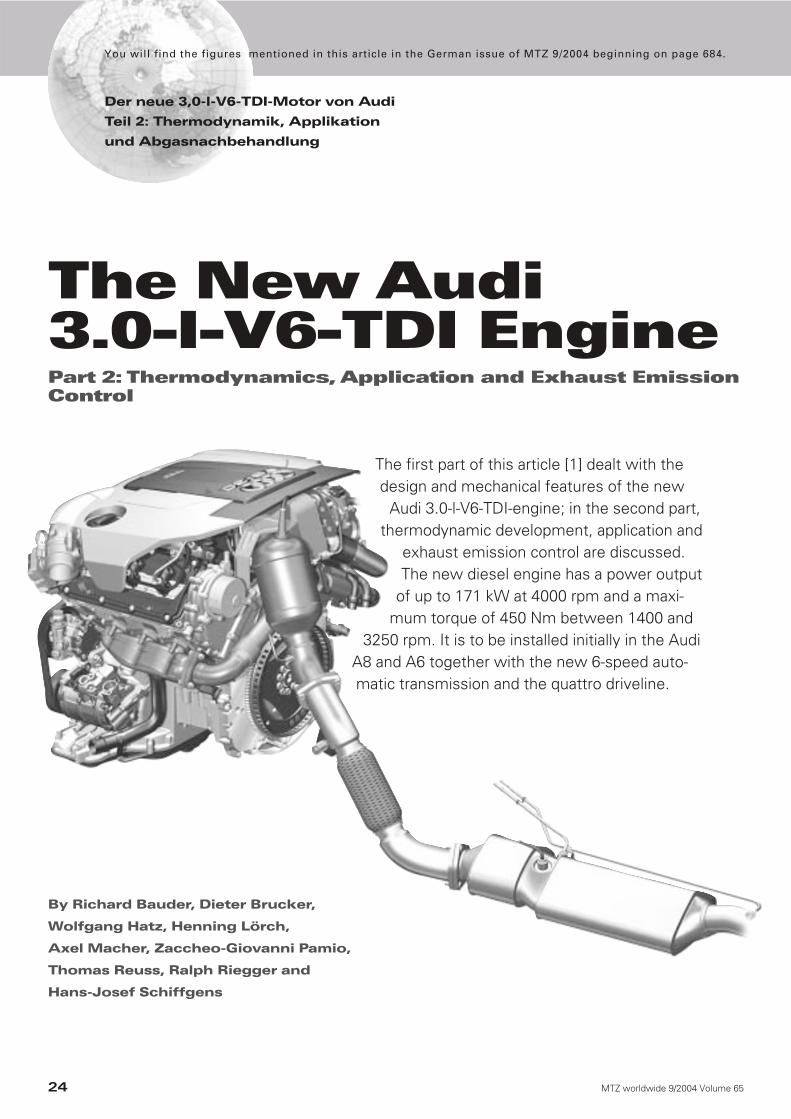
The first part of this article [1] dealt with thedesign and mechanical features of the new
Audi 3.0-l-V6-TDI-engine; in the second part,thermodynamic development, application and
exhaust emission control are discussed.The new diesel engine has a power output
of up to 171 kW at 4000 rpm and a maxi-mum torque of 450 Nm between 1400 and
3250 rpm. It is to be installed initially in the AudiA8 and A6 together with the new 6-speed auto-matic transmission and the quattro driveline.
By Richard Bauder, Dieter Brucker,
Wolfgang Hatz, Henning Lörch,
Axel Macher, Zaccheo-Giovanni Pamio,
Thomas Reuss, Ralph Riegger and
Hans-Josef Schiffgens
Der neue 3,0-l-V6-TDI-Motor von Audi
Teil 2: Thermodynamik, Applikation
und Abgasnachbehandlung
You will find the figures mentioned in this article in the German issue of MTZ 9/2004 beginning on page 684.
The New Audi 3.0-l-V6-TDI EnginePart 2: Thermodynamics, Application and Exhaust EmissionControl
25MTZ worldwide 9/2004 Volume 65
1 Introduction and Description of Task
The Audi 2.5-l-V6-TDI-engine went intoproduction in 1997: in its final developmentstage, it had a maximum power output of132 kW was able to comply with Euro 4 ex-haust emission limits as a production en-gine even when installed in large cars [2].For the new Audi A6 and A8, a V6-TDI-en-gine with a displacement of 3 litres was de-veloped. Following the 4.0-l-V8-TDI [3] it isthe second diesel engine to be based on thenew Audi V-engine family. However, thecylinder centres have been widened from88 to 90 mm. Features of this engine familyare the installation of the chain drives atthe transmission end, and the extremelyshort, compact design that results. For thefirst time on an Audi V6-TDI engine, fuel in-jection is by a third-generation Bosch com-mon rail system with piezo injectors [4].The maximum injection pressure is 1600bar.
Development objectives in the thermo-dynamics and exhaust emission control ar-eas were:■ Highest possible specific power output■ High torque■ Best possible performance, in particularinitial accelerator-pedal response and ac-celeration, allied to low fuel consumption ■ Excellent combustion noise■ Compliance with the stringent EU 4 ex-haust emission limits by means of internalengine measures only■ Option of maintenance-free CSF (CoatedSoot Filter) particle filter system.
In order to utilise the potential of severalhighly complex systems, extensive investi-gations of the combustion process and inthe application area were conducted. Sys-tematic examination and analysis of the in-teractions between the various systems andparameters was only possible with the aidof the design of experiment (DoE) principle.The results were used to define the combus-tion process and the application data.
2 Combustion Process andApplication
Already familiar from the 4.0-l-V8-TDI, theAudi TDI combustion process with fourvalves per cylinder and common rail fuelsupply to the injectors was completely re-vised for the new engine.
Particular attention was paid to the fol-lowing factors influencing the diesel com-bustion principle:■ Swirl control and combustion chamberfilling■ Combustion chamber shape and com-pression ratio
■ Fuel injection system with multi-stageinjection■ Exhaust gas recirculation with con-trolled cooling■ Turbocharging and charge-air intercool-ing.
2.1 Four Valves per Cylinderand Electronic Swirl ControlThe 3.0-l-V6-TDI is the first engine to usethe new four-valve combustion chamberconcept. In order to achieve higher me-chanical strength and better cooling (cross-flow instead of longitudinal flow), the star-pattern valve layout was turned slightly sothat each pair of inlet and exhaust valves isoperated by one camshaft, Figure 1.
In conjunction with the controlled swirlflap, the ports were systematically devel-oped with a view to increasing the spreadof the swirl, in other words enlarging therange between low and high degrees ofswirl. The electronically controlled swirlflap enables intermediate positions to beselected for the first time in accordancewith the mapped characteristic, Figure 2.
With the spiral port closed, a high de-gree of swirl approx. 1.35 is obtained. Whenthe flap is open, the swirl is reduced to nomore than 0.4, with a high flow rate of 0.11.The previous 2.5-l-V6-TDI engine achievedan 0.09 flow rate at a fixed degree of swirl0.67.
At low engine speeds and loads, the flapis closed in order to achieve minimumemissions, in other words the degree ofswirl is high. At low engines speeds withhigh loads, the lowest emissions areachieved in an intermediate, medium-swirlposition. At high engine speeds and whenmaximum power is called for, the swirl flapis fully open and the low-swirl range is ac-tive. The influence of swirl flap position onparticle emissions at a selected operatingpoint is shown in Figure 3.
The use of controlled swirl flaps also per-mits much lower particle emission valuesto be achieved at the specified EU 4 NOx lev-els. This is beneficial at relatively highloads, where a completely closed inlet portwould lead to poorer cylinder filling andtherefore to increased particle emissions.Removal of throttling effects is also desir-able from a fuel consumption point of view.This possibility is of particular importancewhen the engine is combined with auto-matic transmission and the quattro drive-line, since this imposes higher averageloads than the standard driveline.
Use of the position-controlled swirl flap,which permits an optimum compromisebetween emission, consumption andtorque/power output demands in accor-dance with load and engine speed, repre-
sents a basis for compliance with the EU 4exhaust emission limits with the aid of in-ternal engine measures only.
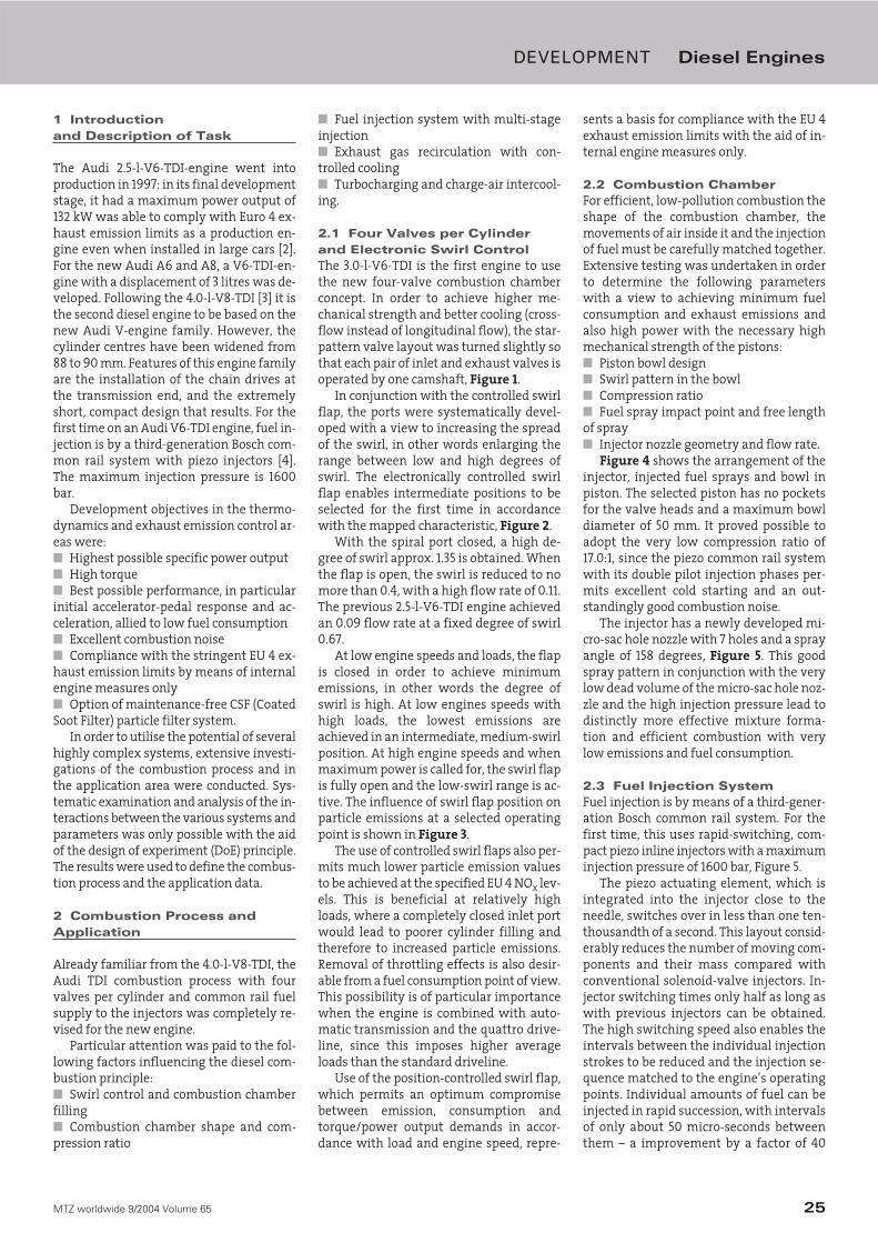
2.2 Combustion ChamberFor efficient, low-pollution combustion theshape of the combustion chamber, themovements of air inside it and the injectionof fuel must be carefully matched together.Extensive testing was undertaken in orderto determine the following parameterswith a view to achieving minimum fuelconsumption and exhaust emissions andalso high power with the necessary highmechanical strength of the pistons:■ Piston bowl design■ Swirl pattern in the bowl■ Compression ratio■ Fuel spray impact point and free lengthof spray■ Injector nozzle geometry and flow rate.
Figure 4 shows the arrangement of theinjector, injected fuel sprays and bowl inpiston. The selected piston has no pocketsfor the valve heads and a maximum bowldiameter of 50 mm. It proved possible toadopt the very low compression ratio of17.0:1, since the piezo common rail systemwith its double pilot injection phases per-mits excellent cold starting and an out-standingly good combustion noise.
The injector has a newly developed mi-cro-sac hole nozzle with 7 holes and a sprayangle of 158 degrees, Figure 5. This goodspray pattern in conjunction with the verylow dead volume of the micro-sac hole noz-zle and the high injection pressure lead todistinctly more effective mixture forma-tion and efficient combustion with verylow emissions and fuel consumption.
2.3 Fuel Injection SystemFuel injection is by means of a third-gener-ation Bosch common rail system. For thefirst time, this uses rapid-switching, com-pact piezo inline injectors with a maximuminjection pressure of 1600 bar, Figure 5.
The piezo actuating element, which isintegrated into the injector close to theneedle, switches over in less than one ten-thousandth of a second. This layout consid-erably reduces the number of moving com-ponents and their mass compared withconventional solenoid-valve injectors. In-jector switching times only half as long aswith previous injectors can be obtained.The high switching speed also enables theintervals between the individual injectionstrokes to be reduced and the injection se-quence matched to the engine’s operatingpoints. Individual amounts of fuel can beinjected in rapid succession, with intervalsof only about 50 micro-seconds betweenthem – a improvement by a factor of 40
DEVELOPMENT Diesel Engines
26 MTZ worldwide 9/2004 Volume 65
compared with second-generation equip-ment. The new injectors can deliver up tofive amounts of fuel on each workingstroke of the engine. Furthermore, the min-imum possible pilot injection volumes andthe tolerances have been reduced quiteclearly compared with the second genera-tion, namely from 1.5 to 1.0 mm3/stroke.This is an important precondition for thelowest possible particle emissions. In closecooperation with Bosch, the injector andthe nozzle module were subjected to sig-nificant further development with regardto their long-term volumetric stability, inparticular at high rail pressures.
The influence of the number of pilot in-jection phases on NOx and particle emis-sions at a constant pilot injection volume of1 mm3/stroke is shown in Figure 6. It canclearly be seen that the PM/NOx trade-offbecomes increasingly unfavourable at thenumber of pilot injection phases increases,and that the most satisfactory level ofemissions is obtained without pilot injec-tion. Against this, however, diesel engineswithout pilot fuel injection are unaccept-able on account of their poor combustionnoise.
The high dynamic performance and theresulting flexibility of the piezo injectionsystem enables this conflict of objectivesbetween combustion noise and emissionsto be almost completely eliminated, sincesmoother combustion can be achievedacross the entire operating range withoutserious disadvantages in terms of emis-sions. As an example, the influence of theinterval between pilot and main injectionphases on particle emissions and combus-tion noise at constant NOx emissions isshown at an important engine operatingpoint in Figure 7.
Pilot injection close to the main injectionstroke achieves the best acoustics but poor-er particle emissions, whereas a longer in-terval between the pilot and main injectionphases reduces particle emissions butworsens the noise pattern. A larger pilot-in-jected fuel volume improves the acousticsbut increases particle emissions, but itshould be noted that the volumetric toler-ance demand increases if pilot injectiontakes place only shortly before the main in-jection stroke.
An overview of the influence exerted byinjection parameters on particle emissionsand combustion noise at a constant level ofNOx emissions at a selected engine operat-ing point can be seen in Figure 8. The para-meters investigated here are:■ Number of pilot injection phases ■ Pilot-injection fuel volume■ Interval between pilot injection phases■ Fuel injection pressure.
The fuel injection strategy for the newAudi 3.0-l-V6-TDI was chosen to permit thevery stringent EU 4 exhaust emission limitsto be complied with by means of internalengine measures only, and at the sametime to achieve optimum satisfaction ofcustomers’ wishes in the fuel consumption,noise, power output and torque areas.
A satisfactory idle-speed noise pattern isclearly essential for a car in the luxury class.In this operating condition too, the newpiezo injector system is able to demon-strate significant advantages. As Figure 9shows, the 3.0-l-V6-TDI engine’s combus-tion noise only has a minor influence onengine noise at idle speed.
2.4 Turbocharging and Charge-Air IntercoolingA most important development objectivewas for the engine to produce high torqueeven at low engine speeds and in particularfor the torque to build up spontaneously.This was achieved by means of a tur-
bocharger with variable turbine geometry,supplied by Borg Warner Turbosystems; ithas an electric actuating motor for precise,rapid adjustment of the turbine blades.
Figure 10 shows the difference betweenthe action of a vacuum can and the electricmotor chosen here at constant enginespeed when the boost pressure is varied.The advantages of the electric motor’s con-trol characteristic can be clearly seen:■ Lowest possible hysteresis in the actuat-ing mechanism and thus a clear relation-ship between control movement and boostpressure■ Precise pilot control and thus the bestpossible initial response and the lowestemission levels ■ Position feedback for more accurateEOBD diagnosis.
A temperature sensor at the turbine in-let ensures that the permissible exhausttemperature of 820°C is not exceeded. Thispermits high engine power output withoutthe risk of components being overloaded.
DEVELOPMENT Diesel Engines
Figure 4: Combustion
chamber
2.2 Combustion Chamber
27MTZ worldwide 9/2004 Volume 65
Optimum charge-air intercooling is sim-ilarly important for spontaneous torquebuild-up. For reasons of available space,two side-mounted charge-air intercoolersare installed. They are arranged to operatein parallel so that low charge-air tempera-tures (Δt = 25 K above ambient) and pres-sure losses (120 mbar at nominal poweroutput) can be achieved, Figure 11.
2.5 Exhaust Gas RecirculationControlled exhaust gas recirculation withthe exhaust gas cooled to a greater or lesserextent is currently the most effectivemeans of achieving a significant reductionin untreated NOx and particle emissions.By making it possible to switch the EGRcooler into and out of circuit, considerableimprovements to HC and CO emissions inparticular can be obtained, Figure 12. Therecirculated exhaust gas is cooled to agreater or lesser extent according to engineoperating temperature and load require-ment.
Further important parameters for an ef-ficient EGR system are good homogeneityof the air and the exhaust gas, and uniformvolumetric distribution between the cylin-ders of the engine. This is of decisive impor-tance in particular for EU 4 engines usingEGR levels of up to 60 %. A number of de-sign variants was assessed and optimisedby means of coupled 1D/3D CFD computing.The basis for good results was found to bethe introduction of the exhaust gas shortlyafter the throttle flap, distribution to thetwo cylinder banks along a lengthy mixingpath and detail optimisation of the EGR in-troduction point, Figure 13.
3 Engine Management
The latest EDC16CP generation of controlunit from Bosch is used for engine manage-ment. It has a high-performance 32-bitprocessor with a 56 MHz cycle rate andmemory capacity for more than 12,000 ap-plication parameters.
Extended regulating functions in theelectronic engine management systemsupport the accuracy of the piezo inline in-jectors, in particular with regard to consis-tent long-term emissions, acoustics androad behaviour:■ Injector quantity calibration (Germanabbreviation IMA) reduces volumetric dif-ferences between the individual injectorsused in the engine almost to zero.■ Zero-volume calibration (German abbre-viation NMK) corrects the pilot injectionvolumes for each cylinder individually byevaluating the speed signal and varyingthe injector actuation period when the en-gine is coasting.
■ Volumetric equalisation control (Ger-man abbreviation MAR) aligns the individ-ual cylinders’ contribution to total torquearound a neutral mean value by analysingthe speed signal when coasting to deter-mine torsional vibration of the crankshaftand modify the injected fuel volume ac-cordingly.■ Mean Volume Adaptation (German ab-breviation MMA) detects any displacementof the air ratio by the lambda probe in theexhaust gas line and corrects it by interven-tion in the EGR control system.■ Nominal Voltage Calibration (NVC),monitors the individual electrical con-sumption of the piezo actuators and cor-rects this value if necessary in order to en-sure that the injector control valve’s strokeremains consistent.
The effect of these electronic correctingfunctions on particle and NOx emissions isshown in Figure 14.
4 Exhaust Emission Control
The version without DPF already outper-forms the EU 4 exhaust emission limitswhen installed in the Audi A8. Audi also of-fers a diesel particle filter for sale that re-duces the engine’s already low particleemissions by more than 90 % measured bymass. The exhaust system comprises an ox-idating catalytic converter installed close tothe engine, an underfloor catalytic convert-er and, directly attached to it, a particle fil-ter, Figure 15.
As on the version without particle filter,the close-to-the-engine catalytic converterensures that hydrocarbons and carbonmonoxide are broken down rapidly and theEU 4 limits complied with. The ceramic sili-con carbide particle filter consists of chan-nels arranged in parallel, with alternatingchannels sealed at opposite ends. The ex-haust gas entering the device has to passthrough the porous walls, with the resultthat the soot particles are trapped in the in-let channels. The volume of the filter is de-signed to permit the vehicle to cover about200,000 kilometres without routine main-tenance being needed.
In conformity with the V6 TDI high-per-formance concept, a novel type of thin-walled substrate has been adopted, the firsttime it has appeared on the market. By re-ducing the wall thickness by 37 % comparedwith the conventional standard substrate,exhaust back pressure has been lowered byas much as 20 %. In conjunction with a cat-alytically effective filter coating, active filterregeneration takes place efficiently at tem-peratures no higher than 580-600 °C.
Together with the increased number ofcells making up the thin-walled substrate,
the time needed for regeneration is about20 % shorter, Figure 16. This minimises theconsumption of additional fuel ad makesregeneration possible on a more reliablebasis, for instance even when the vehicle isonly used for short journeys.
Regeneration is initiated when the par-ticle filter has reached its maximum per-missible particle content. This may take upto 2,000 kilometres. The particle content isidentified, as shown in Figure 17, by way oftwo models: a simulation model uses datasaved in the control unit to calculate sta-tionary and dynamic soot mass emissions(mCin), taking into account the reduction inthe previously deposited particle mass as aresult of NO2 effects and thermal burning-off with O2 (mCout).
In order to ensure that the simulationcalculation is as accurate as possible, thereis in addition to the temperature sensors a‘lambda probe’ to determine the mass flowof O2 and establish the mass flow of sootparticles in dynamic conditions. In addi-tion, the particle content is determined byevaluating the measured pressure differen-tial across the particle filter.
Extensive intervention in the enginemanagement process is necessary in orderto obtain the regeneration temperature of580 °C in the equipment positioned underthe floor of the vehicle. To obtain the de-sired effect, the quantity of injected fuel,the number of fuel injection strokes andthe start of the processes are modified insuch a way that the temperature is in-creased with no adverse effects on the en-gine’s acoustic pattern or the amount oftorque it produces. Optimum overall condi-tions for this are created by Audi’s adop-tion of the piezo common-rail injectionsystem, which is capable of injecting fuelin up to five successive phases as deter-mined by the mapped engine characteris-tic, Figure 18.
In order to heat up the combustionchambers, the incoming flow of air is throt-tled and the amount of recirculated ex-haust gas reduced in order to increase thevolume of oxygen.
In addition to these internal enginemeasures, the exhaust gas temperature isalso raised by exothermic conversion of un-burned hydrocarbons in the oxidating cata-lysts, Figure 19.
The combination of a highly flexible fu-el injection system, a novel form of sub-strate and an intelligent regeneration strat-egy in conjunction with low untreated par-ticle emissions has enabled an exhaustemission control system to be realised thatsatisfies Audi’s high standards to the maxi-mum possible extent.
DEVELOPMENT Diesel Engines
28 MTZ worldwide 9/2004 Volume 65
5 Engine Results
The principal thermodynamic features ofthe new 3.0-l-V6-TDI-engine are sum-marised in Table 1. The V6-TDI-engine’storque and power-output potential can beseen from the full-load graph, Figure 20.The impressively high, flat torque curveshould be noted. The maximum torque of450 Nm is reached at an engine speed aslow as 1450 rpm, and remains available upto 3250 rpm. The smoke values for the ver-sion without DPF are at an extremely lowlevel: for a large part of the operatingrange, the smoke figure is below 1. Fuelconsumption is also satisfactory: withinthe nominal power-output range the spe-cific fuel consumption is only 235 g/kWh.At full load, the additional fuel consump-tion due to the DPF system is in the regionof 1 - 2 %.
The specific power output of 57.6 kW/l iscurrently the highest achieved by any six-cylinder passenger-car diesel engine, Fig-ure 21.
The fuel consumption characteristic ofthe new V6-TDI-engine at the optimum op-erating point is an outstandingly low 202g/KWh, Figure 22. the basis for the very flatiso-lines are the combustion principle de-scribed earlier and also measures adoptedto reduce friction in the engine, such as theuse of roller cam followers and UV photonhoning, and a crankcase and engine blockwith low distortion levels.
6 Vehicle Results
This is the first Audi model to employ thenew six-speed tiptronic automatic trans-mission and quattro all-wheel drive in con-junction with the V6-TDI-engine. The highpower output and torque values make itpossible to achieve excellent road perfor-mance in all situations. At the same time,the very stringent EU 4 exhaust emissionlimits have been achieved by internal en-gine measures alone. In order to reduce thealready low particle emissions still further,a particle filter is offered as an optional ex-tra. Emissions in the MVEG test with andwithout DPF are shown in Figure 23.
Thanks to the very latest filtration tech-nology, the particle filter application en-ables the same road performance to be pro-vided. Consumption of this version in theMVEG test is only 0.1 litre per 100 km higherthan without DPF. Table 2 shows perfor-mance and fuel consumption values for the3.0-l V6-TDI-engine in the Audi A8 with au-tomatic transmission.
7 Summary
The 3.0-l-V6-TDI engine that has now beendeveloped is the first diesel engine in theAudi V-engine family with cylinder centresspaced at 90 mm.
With a power output of up to 171 KW (233bhp) and a maximum torque of 450 Nm, itis currently the most powerful six-cylinderpassenger-car diesel engine anywhere inthe world, with the result that the perfor-mance of the cars in which it is installed isequally impressive.
Even in a luxury car and when com-bined with automatic transmission andquattro all-wheel drive, this engine is ableto comply with the stringent EU 4 exhaustemission limits by means of internal mea-sures alone.
The 3.0-l-V6-TDI-engine is the first to usepiezo inline injectors with a maximum in-jection pressure of 1600 bar. In addition togood performance figures, this injectionsystem permits outstanding refinementand an agreeably acoustic combustion pat-tern. In addition, the particle filter can beoptimally regenerated with the aid of oneor two fuel injection phases.
The new 3.0-l-V6-TDI engine is currentlythe passenger-car diesel engine with thegreatest potential for the protection of theenvironment and natural resources avail-able anywhere in the world.
References
[1] Anton, C.; Bach, M.; Bauder, R.; Franzke, G.;Hatz, W.; Hoffmann, H.; Ribes-Navarro, S.:The new 3.0-l-V6-TDI from Audi – Part 1: De-sign and Mechanical Features; In: MTZ 65(2004), No. 78, Page 518
[2] Bauder, R., Bechle, S., Dorsch, W., Pölzl, H.-W., Riegger, R. and Schiffgens, H.-J.: The newV6-TDI engine from Audi – Part 2: Thermody-namics; In: MTZ 64 (2003), No. 7-8, Page 606
[3] Bauder, R., Hatz, W., Pölzl, H.-W., Michels, E.,Schiffgens, H.-J., Streng, C. and Wimmer, W.:Audi 4.0 V8-TDI – Part 2: Thermodynamics andApplication. In: MTZ 64 (2003) No. 10, Page860
[4] Hummel, K., Boecking, F., Gross, J., Stein, J.-O. and Dohle, U.: Third-generation Passenger-car Common-rail Fuel Injection from Boschwith Piezo Inline Injectors. In: MTZ 65 (2004),No. 3, Page 180
DEVELOPMENT Diesel Engines