the open petroleum engineering journal the open petroleum engineering journal, 2017, 10, ... study...
TRANSCRIPT
Send Orders for Reprints to [email protected]
48 The Open Petroleum Engineering Journal, 2017, 10, 48-63
1874-8341/17 2017 Bentham Open
The Open Petroleum EngineeringJournal
Content list available at: www.benthamopen.com/TOPEJ/
DOI: 10.2174/1874834101701010048
RESEARCH ARTICLE
Study on Wellbore Stability of Shallow Sediments in DeepwaterDrilling
Jun Zhang1,*, Chi Ai1, Bo Zeng2, Yuwei Li1 and Jia Zeng1
1School of Petroleum Engineering, Northeast Petroleum University, Daqing, 163318, P.R. China2Research Institute of Petroleum Exploration & Development-Langfang Branch, PetroChina, Langfang, 065007, P.R.China
Received: November 10, 2016 Revised: January 07, 2017 Accepted: February 09, 2017
Abstract:
Background:
The deepwater shallow formation has low fracture pressure and narrow safe window of mud density, which results in a high risk ofwellbore instability in this kind of formation.
Objective:
Without considering the plastic state of shallow formation around the borehole or the influence of in-situ stress difference onwellbore stability, the prediction accuracy of the traditional wellbore stability analysis models are relatively low. This paper canprovide a reliable method to accurately predict the safe window of drilling fluid density.
Method:
In this paper, the shallow formation around the borehole is divided into plastic zone and elastic zone considering it under non-uniform in-situ stress. The collapse pressure formula of shallow formation is derived by taking the shrinkage rate of the borehole asthe instability criterion. The fracturing pressure calculation model of shallow sediment under non-uniform in-situ stress is derived bycombining the theory of excess pore pressure and hydraulic fracturing.
Conclusion:
The calculated results indicate that the horizontal in-situ stress difference has a significant effect on the shape of the plastic zone, theshrinkage rate of borehole, collapse pressure and fracturing pressure. The calculated results are in good agreement with the field testresults, and the prediction accuracy of this model is higher than that of other traditional models.
Keywords: Wellbore stability, Borehole shrinkage rate, Collapse pressure, Excess pore pressure, Fracture pressure, Drilling fluiddensity.
1. INTRODUCTION
Marine oil and gas resources are very rich in the world, which is much more difficult to develop than in onshore oilfield [1, 2]. Deepwater shallow sediment is less-consolidated and has high permeability and low strength. Because of itsunique mechanical properties, the shallow formation around the borehole often has higher collapse pressure and lowerfracture pressure. As a result, the narrow safe window of drilling fluid density usually causes the occurrence of drillingaccidents [3 - 5].
Many studies have been conducted on wellbore stability of deepwater shallow sediments, for example, Wojtanowicz
* Address correspondence to this authors at Northeast Petroleum University, Daqing, P.R. China, No.199, Fazhan Road, High-Tech DevelopmentDistrict, Daqing City, Heilongjiang Province, P.R. China; Tel: +86-13091693160; E-mails: [email protected], 2:[email protected]
Study on Wellbore Stability of Shallow Sediments The Open Petroleum Engineering Journal, 2017, Volume 10 49
et al. established an elastic model which can reflect the mechanical characteristics of deepwater shallow sediment, andstudied its fracturing pressure based on both theoretical analysis and numerical simulation [6]; R. Chhajlani and Z. Q.Zheng analyzed the stability of borehole wall in Mexico Bay deepwater oil field based on the linear elastic constitutivemodel and Mohr-Coulomb strength criterion and used the research results to guide the field work [7]. However, thetraditional models of borehole wall stability analysis are based on elastic mechanics [8, 9]. Since the shallow sedimentis similar to saturated soil, even if the stress around the borehole exceeds the rock strength, the borehole will remainstable and not collapse or fracture immediately. Therefore, the traditional analytical model cannot reveal the realborehole instability mechanism of deepwater shallow sediment. D. G. Ritter and B. Grollimund studied boreholestability in Brazil deepwater oil field based on the method of quantitative risk assessment, and the results showed thatthe prediction accuracy of in-situ stress and formation strength had the greatest influence on the analysis results [10]. E.Kaarstad and B. S. Aadnoy established an elastoplastic model for the fracturing pressure calculation of shallowformation based on the field data of deepwater drilling in Norway. But the empirical model based on field practicecannot truly reflect the actual stress state around the borehole [11, 12]. L. Yan et al. divided the shallow formationaround the borehole into plastic zone and elastic zone and deduced the collapse pressure and fracturing pressurecalculation formula based on the assumptions that the formation is in a uniform stress state and the plastic zone aroundthe borehole is circular [13]. However, many researches and field tests showed that the horizontal stress difference has asignificant impact on the collapse pressure and fracturing pressure although the horizontal stress difference in deepwatershallow formation is smaller than that in terrestrial formation. Therefore, the prediction accuracy of the calculationmodel under the assumption of uniform in-situ stress is relatively low.
In this paper, considering the shallow formation is in the condition of non-uniform in-situ stress and combining therock mechanics and some theories of soil mechanics, the shallow formation around the borehole is divided into plasticzone and elastic zone. The formulas for calculating the plastic zone boundary and the shrinkage rate of the boreholeunder non-uniform in-situ stress are deduced by assuming that the stress-strain relation in the plastic zone is inaccordance with the theory of large deformation. The shrinkage rate is chosen as the criterion of borehole collapse, andthe collapse pressure formula of shallow formation is obtained. Then the fracturing pressure calculation model ofshallow sediment under non-uniform in-situ stress is derived by combining the theory of excess pore pressure andhydraulic fracturing theory.
2. ESTABLISHMENT OF MECHANICAL MODEL
2.1. Characteristics of Deepwater Drilling and Wellbore Stability in Shallow Formation
Due to the lack of sufficient geological and logging data in deepwater drilling, the errors of calculation results ofsafety drilling fluid density window by the traditional models are always large. It is very important to establish a modelto accurately predict the collapse pressure and fracture pressure of deepwater shallow formation. Although there aregreat differences in the physical and mechanical properties between the deepwater shallow sediment and the terrestrialformation, their research methods of borehole stability are same.
However, it is more difficult to analyze the wellbore stability in deepwater shallow formation. Firstly, overburdenpressure of deepwater shallow sediment is lower than that of the terrestrial formation, which leads to a low fracturingpressure of shallow formation and a narrow safe window of drilling fluid density. Therefore, it is very important fordeepwater drilling to improve the prediction accuracy of the safe window of drilling fluid density. Secondly, deepwatershallow formation is characterized by high porosity, high permeability, weak cementation and low strength, which isprone to transform into plastic state and appear as large deformation under the action of in-situ stress. In the process ofdrilling, some serious accidents often occur in shallow formation, such as wellbore shrinkage, drill pipe sticking andwellbore collapse. Thirdly, shallow formation may have shallow gas and shallow water, and well blowout or gaschanneling is easy to occur. Because the shallow gas and shallow water can only be formed under special conditions,the first two problems are more important to evaluate the well bore stability in deepwater shallow formation.
2.2. Basic Assumptions and Mechanical Models
Deepwater shallow sediment is similar to saturated soil and can be considered as homogeneous, isotropic andideally elastoplastic material. The traditional elastic model is relatively conservative in calculating the collapse pressureand fracturing pressure of shallow sediment. Many researches have proved that even if there is a certain plastic areaappeared around the borehole in the shallow formation, the borehole wall can still maintain stability. Considering theeffect of non-uniform in-situ stress, the mechanical model is established, as shown in Fig. (1). The shallow formation
50 The Open Petroleum Engineering Journal, 2017, Volume 10 Zhang et al.
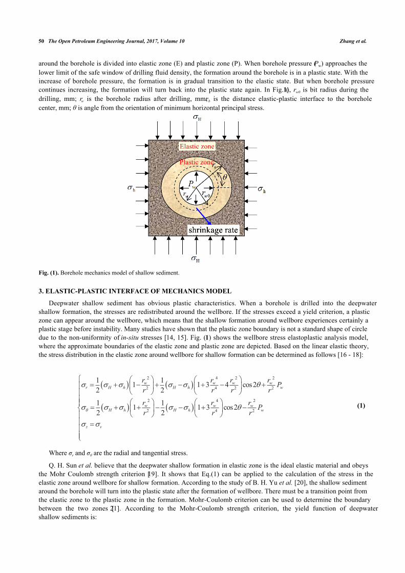
around the borehole is divided into elastic zone (E) and plastic zone (P). When borehole pressure (Pw) approaches thelower limit of the safe window of drilling fluid density, the formation around the borehole is in a plastic state. With theincrease of borehole pressure, the formation is in gradual transition to the elastic state. But when borehole pressurecontinues increasing, the formation will turn back into the plastic state again. In Fig. (1), rw0 is bit radius during thedrilling, mm; rw is the borehole radius after drilling, mm; rb is the distance elastic-plastic interface to the boreholecenter, mm; θ is angle from the orientation of minimum horizontal principal stress.
Fig. (1). Borehole mechanics model of shallow sediment.
3. ELASTIC-PLASTIC INTERFACE OF MECHANICS MODEL
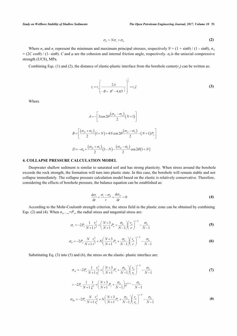
Deepwater shallow sediment has obvious plastic characteristics. When a borehole is drilled into the deepwatershallow formation, the stresses are redistributed around the wellbore. If the stresses exceed a yield criterion, a plasticzone can appear around the wellbore, which means that the shallow formation around wellbore experiences certainly aplastic stage before instability. Many studies have shown that the plastic zone boundary is not a standard shape of circledue to the non-uniformity of in-situ stresses [14, 15]. Fig. (1) shows the wellbore stress elastoplastic analysis model,where the approximate boundaries of the elastic zone and plastic zone are depicted. Based on the linear elastic theory,the stress distribution in the elastic zone around wellbore for shallow formation can be determined as follows [16 - 18]:
(1)
Where σr and σθ are the radial and tangential stress.
Q. H. Sun et al. believe that the deepwater shallow formation in elastic zone is the ideal elastic material and obeysthe Mohr Coulomb strength criterion [19]. It shows that Eq.(1) can be applied to the calculation of the stress in theelastic zone around wellbore for shallow formation. According to the study of B. H. Yu et al. [20], the shallow sedimentaround the borehole will turn into the plastic state after the formation of wellbore. There must be a transition point fromthe elastic zone to the plastic zone in the formation. Mohr-Coulomb criterion can be used to determine the boundarybetween the two zones [21]. According to the Mohr-Coulomb strength criterion, the yield function of deepwatershallow sediments is:
� �
� �
2 4 2 2
2 4 2 2
2 4 2
2 4 2
1 11 1 3 4 cos22 2
1 11 1 3 cos22 2
w w w wr H h H h w
w w wH h H h w
z v
r r r r Pr r r r
r r r Pr r r�
� � � � � �
� � � � � �
� �
� � �� � � � � � � �� � � � �
� � � ��� � �� � � � � � � �� � � � �
� � � ��� ����
Study on Wellbore Stability of Shallow Sediments The Open Petroleum Engineering Journal, 2017, Volume 10 51
(2)
Where σθ and σr represent the minimum and maximum principal stresses, respectively N = (1 + sinθ) / (1 - sinθ), σ 0
= (2C cosθ) / (1- sinθ). C and φ are the cohesion and internal friction angle, respectively. σ0 is the uniaxial compressivestrength (UCS), MPa.
Combining Eqs. (1) and (2), the distance of elastic-plastic interface from the borehole center(rb) can be written as:
(3)
Where
4. COLLAPSE PRESSURE CALCULATION MODEL
Deepwater shallow sediment is similar to saturated soil and has strong plasticity. When stress around the boreholeexceeds the rock strength, the formation will turn into plastic state. In this case, the borehole will remain stable and notcollapse immediately. The collapse pressure calculation model based on the elastic is relatively conservative. Therefore,considering the effects of borehole pressure, the balance equation can be established as:
(4)
According to the Mohr-Coulomb strength criterion, the stress field in the plastic zone can be obtained by combiningEqs. (2) and (4). When σr|r = rw=Pw, the radial stress and tangential stress are:
(5)
(6)
Substituting Eq. (3) into (5) and (6), the stress on the elastic–plastic interface are:
(7)
(8)
12
12 2
2
4b w w
Ar r rB B AD
� �� �� �� �� �� � �� �
� �3cos2 12
H hA N� �
��� �
� � �� �� �
� � � �1 4 cos2 12 2
H h H hwB N N N P
� � � ��
� �� �� � � � �� �� �
� � � �0 1 cos2 12 2
H h H hD N N� � � �
� �� �
�� � � � �
dd 0d d
rfrr
r r r� �� �� �� � �
120 0
21 32
1 1 1 1
Nw w
r w wr rNP P
N r N N r N� ��
�� � �� � � � �� �� �� � � �� �� �
120 0
232
1 1 1 1
Nw w
w wr rN NP N P
N r N N r N�� ��
�� � �� � � � �� �� �� � � �� �� �
120 0
2
10 02
1 321 1 1 1
1 1 321 1 1 1
Nw w
rb w wb b
Nw w
r rNP PN r N N r N
NP PN N N N
� ��
� ���
�
�
�� �� � � � �� �� �� � � �� �� �
� �� � � � �� �� � � �� �
120 0
232
1 1 1 1
Nw w
b w wb b
r rN NP N PN r N N r N�
� ���
�� �� � � � �� �� �� � � �� �� �
0rN�� � �� �

52 The Open Petroleum Engineering Journal, 2017, Volume 10 Zhang et al.
Many studies have shown that deepwater shallow sediment has a short diagenetic time. It is less-consolidated andhas all physical properties of saturated soft soil [22, 23]. Therefore, the plastic zone around the borehole for shallowformation is controlled by the consolidation theory of saturated soil [24]. It is not suitable to analyze the stability ofborehole wall with the traditional porous elastic theory because of the strong plasticity of shallow formation near theborehole wall. Y. Jin et al. have studied the borehole shrinkage deformation of salt gypsum formation and point out thatthe small deformation theory cannot describe the deformation law of the elastic-plastic formation, and the elastic-plasticdeformation law of soft rock must be solved by large deformation theory [25]. The study of L. Yan et al. also suggeststhat the deformation of the plastic zone around the borehole for deepwater shallow sediment satisfies the largedeformation theory. According to the large deformation theory, we can get the following formulas:
(9)
Where εr is the radial strain, εθ is the tangential strain; u is the formation displacement. Deepwater shallow sedimentis similar to saturated soil which is undrained during the drilling, so the volumetric strain of the plastic zone is 0.
(10)
Assuming the displacement on the elastic-plastic interface is μb .
(11)
Zhou(2002) deduced the displacement field around borehole under uniform in-situ stress [26]. Considering thedifference between maximum and minimum horizontal principal stress, the displacement on the elastic-plastic interfacein non-uniform in-situ stress field can be written as
(12)
The displacement in the plastic zone can be obtained by substituting Eq. (12) into Eq. (11).
(13)
By substituting Eqs. (3) and (7) into (10), when r=rw, the borehole shrinkage rate of shallow sediments is obtained.
(14)
The collapse pressure calculation formula under the control of borehole shrinkage rate can be written as:
(15)
In deepwater shallow sediments, the borehole does not directly collapse. However, if the density of drilling fluid istoo low, it will cause serious borehole shrinkage, which will influence wellbore stability and subsequent cementingoperation. By (14) and (15), the shrinkage rate of borehole and the collapse pressure under the allowable shrinkage ratecan be calculated. Many scholars have studied the collapse pressure of elastic-plastic formation on the basis of boreholeshrinkage [27 - 29]. J.Q. Liu believe that when the stress state of the borehole wall exceeds the limit stress of the elastic-plastic formation, the formation of the surrounding rock will turn into the plastic state, which makes the radius of theborehole decrease continuously. When the borehole shrinkage rate reaches a critical value, the borehole wall willcollapse [30]. Y. Jin et al. and Y. Yang et al. suggest that borehole shrinkage rate can be used as the borehole instabilitycriterion for plastic formation [15, 31]. The above studies indicate that the collapse pressure calculation formula of
0
lnrdrdr
� �
� � � �� �
, 0
ln rr��
�� � � �
� �
0v r �� � �� � �
� �2 22 2r b b br r u r r u� � � � �
� �3 cos2 24rb H h H h rp bu rE
� � � � � �� �� � � � �� �
� � �2 20 3 cos2 2 / 2r w w b H h H h rbu r r r r r E� � � � � �� � � � � � � � �� �� �
� � �0 00
2
212 632 3 cos2 6
1 1 1 1
w
NwwH h H h w
r EP Nr E P
N N N N� �� � � � � � �
�
�� �� � � � � � � �� � � �� � � � � �� �
� � �2
0 02 2 3 cos2 6 11
Nwc H h H h
w
rP E Er N
�� � � � � � � �
� � � � � � � �� �� � � � �� �

Study on Wellbore Stability of Shallow Sediments The Open Petroleum Engineering Journal, 2017, Volume 10 53
deepwater shallow sediments under the control of different shrinkage rates is reasonable and appropriate.
5. FRACTURE PRESSURE CALCULATION MODEL
Different from terrestrial formation, the deepwater shallow formation around the wellbore will turn into plastic statebefore its fracturing. Shallow sediments are under the control of saturated soil consolidation theory. When the porepressure is equal to the external pressure, the formation is under critical condition. The effective stress around theborehole will turn into a tensile stress if the pore pressure exceeds the critical value, and the formation will fracture ifthe tensile stress exceeds its tensile strength. At that time, the borehole pressure is the fracturing pressure. Therefore, thetheory of excess pore pressure is introduced to analyze the changes of pore pressure.
5.1. Fracture Pressure of Vertical Fracture
When the borehole pressure exceeds the horizontal in-situ stress, radial stress on the borehole will be greater thanthe tangential stress and the borehole will turn into plastic state. When the vertical fracture appears on the borehole wall,the stress state on the borehole wall should be expressed as σr>σz>σθ. Thus, the yield function is:
(16)
(17)
Substituting Eq. (16) into Eq. (4), and when σr|r=rw=Pw, the tangential stress and axial stress in the plastic zone can bewritten as
(18)
(19)
Shallow sediment is composed of solid particle skeleton and pores which are full of water. Drilling will result instress concentration around the borehole, and the external pressure will cause a balance between effective stress andpore pressure. The pore pressure generated by external pressure is called excess pore pressure [32, 33]. The solution ofexcess pore pressure is mainly based on the researches of two scholars: Skempton and Henkel [34, 35]. Yan et al.combined their calculation model and rewrote the excess pore pressure formula as
(20)
(21)
(22)
Where ΔP is the excess pore pressure. β is Henkel’s pore pressure parameters, for saturated soil, β=1. A isSkempton’s pore pressure parameter under the effect of deviatoric stress, for shallow sediments, A=0.8 [36, 37]. Δσ1
and Δσ3 are the major and minor principal stress increments.
According to Eq. (18) and (19), the stress increment in plastic zone induced by drilling can be written as
(23)
12
0 02
3 121 1 1 1
NN
wr W W
w
rN N rp pN r N N r N
� ��
�
�� �� � � � �� �� �� � � �� �� �
12
0 02
1 3 121 1 1 1
NN
wW W
w
rN N rp pN N r N N r N�
� ��
�� � �� �� �� � � � �� �� �� �� � � �� �� �� �� �
�3 1 2oct octP A � � � � � � �
�1 2 3 3oct� � � �� � � �� ��
� � �2 2 21 2 2 3 3 1
13oct � � � � � �� � � �� � � �� � � ��
� �
12
0 01 2
3 121 1 1 1
1 cos22
NN
wr W W
w
H h H h
rN N rp pN r N N r N
� �� �
� � � � �
�
�� �� � � � � � � �� �� �� � � �� �� �
� � � �� �� �
wr r r wP
0r N �� � �� �
54 The Open Petroleum Engineering Journal, 2017, Volume 10 Zhang et al.
(24)
On the basis of the plane strain theory, the axial stress increment in plastic zone around the borehole can be writtenas [38]:
(25)
Substituting Eq. (23) and (24) into Eq. (25), the increment of axial stress in the plastic zone is obtained.
(26)
By substituting ΔσOCT and ΔτOCT into (20), the excess pore pressure in the plastic zone can be written as:
(27)
According to the effective stress principle, the effective stress in the plastic zone can be expressed as
(28)
(29)
(30)
Where Pp0 means the in-situ pore pressure.
The above formulas indicate that the tangential and axial effective stress will increase with the increase of the radialdistance. Therefore, the fracture appears on the borehole wall initially, which conforms to the general rule of boreholefracturing [39]. The tangential effective stress on the borehole wall is:
� �
12
0 03 2
1 3 121 1 1 1
1 cos22
NN
wW W
w
H h H h
rN N rp pN N r N N r N�
� �� �
� � � � �
�� � �� �� �� � � � � � � �� �� �� �� � � �� �� �� �� �
� � � �� �� �
�2 2z r �� � � �� �� � � ��
�1
20 0
21 3 1 12
2 1 1 1 1 2
NN
wz W W H h
w
rN N N rp pN N r N N r N
� �� � �
�� � �� � �� �� � � � � � � �� �� �� �� � � �� �� �� �� �
� �
� �
12
02
0
3 3 3 3 1 6 3 126 1 1 1
1 3 3 3 cos21 2 6
NN
wW W
w
H h H h
A N rN N rP p pN N r N N r
AN
�
� � � � � �
�� �� � � � �� �� �� � � � � � �� �� �� � �� �� �� �� ��� � � � �
�
� �
� �
12
02
0
3 3 3 3 1 3 126 1 1 1
1 cos22
NN
wr W W
w
H h H h p
A N rN N rp pN N r N N r
P
��
� � � � �
�� �� � � �� �� �! � � � � � �� �� �� � �� �� �� �� �
� � � � �� �� �
� �
� �
12
02
0
3 3 3 3 1 3 126 1 1 1
1 cos22
NN
wW W
w
H h H h p
A N rN N rp pN N r N N r
P
���
� � � � �
�� �� � � �� �� �! � � � � � �� �� �� � �� �� �� �� �
� � � � �� �� �
� �1
20
02
3 3 3 1 3 126 1 1 1
NN
wz v W W p
w
A N rN N rp p PN N r N N r
�� �
�� �� � �� �� �! � � � � � �� �� �� �� � �� �� �� �� �
Study on Wellbore Stability of Shallow Sediments The Open Petroleum Engineering Journal, 2017, Volume 10 55
(31)
When the vertical fracture appears, the calculation formula of fracturing pressure can be written as:
(32)
5.2. Fracture Pressure of Horizontal Fracture
When the horizontal fracture appears, the stress state in plastic zone satisfies σr>σθ>σz. Therefore the yield functioncan be written as:
(33)
According to Eq. (25), the axial stress on the borehole wall can be obtained.
(34)
Considering Eqs. (32) and (33), when σr=Pw, the tangential and axial stress of the wellhole can be expressed as
(35)
(36)
Then the excess pore pressure is obtained:
(37)
When the fracture appears on the borehole wall, the tangential effective stress should meet Eq. (39).
(38)
When the horizontal fracture appears, the calculation formula of fracturing pressure can be written as:
(39)
The minor value of these two above fracturing pressures ought to be regarded as the fracturing pressure of shallowsediments (Pf):
(40)
� �
� �
0( )
0
3 3 3 3 16 1
1 cos22
rw W
H h H h p t
A Np
N N
P S
���
� � � � �
� � � �! � �� ��� �
� � � � � � �� �� �
� �
� �0
0
16 cos22
13 3 3 3 1
H h H h p
fv
N P StP
NA N
� � � � ��
� "� � � � �� �� #� �� $� ��� � �
0r zN� � �� �
� �
� �
1 1 cos22 2
1 1 cos22 2
z v r H h H h
H h H h�
� � � � � � � �
� � � � � �
� "� � � � � �� �� #� �� $� " �� � � � �� �� #� �� �� �� $
� �02 22
Nw
v H h
N P�
�� � � �
� �� �� �� � � �
�0 / Nz wP� �� �
� 00 1133 2
ww H hv v
N PPP AN N
�� � �� �� �� �� � �� � � � � � �� �� �� �� �
0z z pP P St� �! � � �� ��
� � �
� �
0 03 2 22 13 3 1 1
p v H hfh
N P St N NP
NA N%� � � � �� � � � �
� ��� �
& 'min ,f fv fhP P P�

56 The Open Petroleum Engineering Journal, 2017, Volume 10 Zhang et al.
6. CASE STUDY
In order to verify the theoretical model proposed in this paper. The data of wells in a block from the South ChinaSea are used to case study. The physical and mechanical parameters of the formations are shown in Table 1.
Table 1. Parameters of formations.
Well number Depth/m
σv
/MPaσH
/MPaσh
/MPaC
/MPaφ
/degE
/MPa v Pp0
/MPa1 3230 25.1 25.5 24.7 0.22 4.9 286 0.37 20.72 3453 26.3 27.1 25.8 0.25 4.8 312 0.41 21.83 3357 25.7 26.7 26.2 0.29 4.4 307 0.38 22.1
6.1. Boundary of Plastic Zone and Shrinkage Rate of Borehole
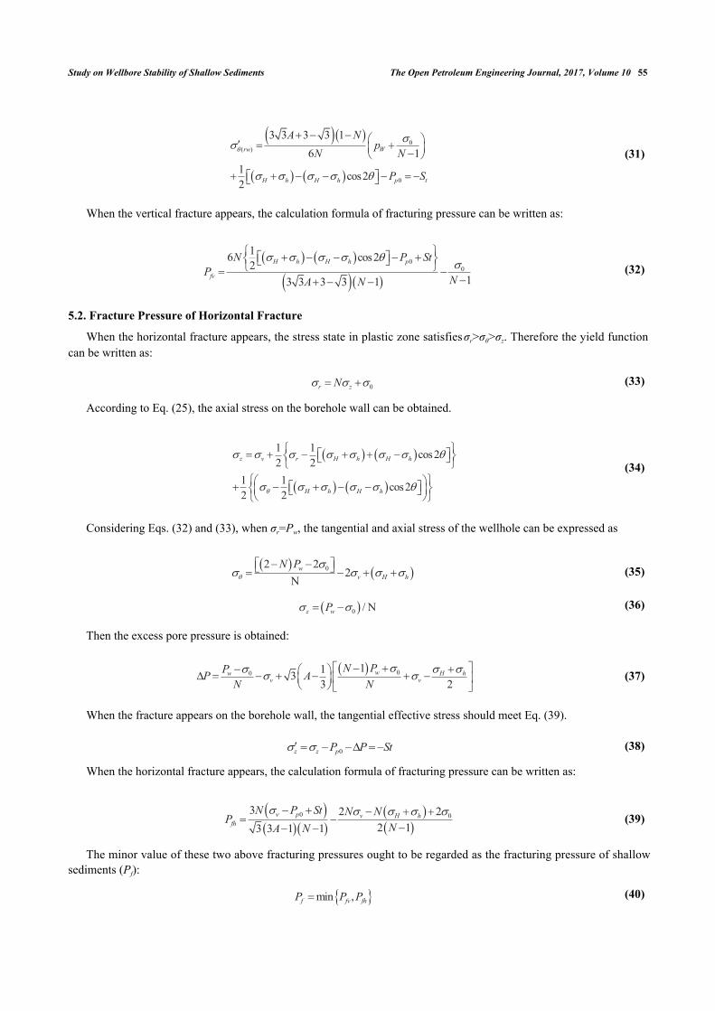
The boundary of plastic zone and borehole shrinkage rate are calculated and analyzed based on the parameters ofWell-1. σh is kept constant and σH is gradually increased, then the variation of the plastic zone boundary and theborehole shrinkage rate under the condition of different horizontal stress difference is obtained. From Fig. (2) we cansee that the horizontal stress difference has a significant impact on the shape of the plastic zone. The plastic zone is acircular under the uniform in-situ stress, and with increase of horizontal stress difference, the plastic zone graduallychanged into an ellipse. Fig. (3) shows the variation rule of borehole shrinkage rate. Many scholars believe that theborehole shrinkage rate is a fixed value, that is, the degrees of shrinkage in different directions are different. However,the calculation results in this paper show that the borehole shrinkage rate changes with θ under the non-uniform in-situstress. With the increase of horizontal stress difference, the anisotropy of borehole shrinkage rate increases. In Fig. (3),when the horizontal stress difference reaches 2.5MPa, the borehole shrinkage rate in the direction of σH is 0.87, and thatin the direction of σh is 2.13. Based on Ewy’s criterion [40], when the borehole shrinkage rate exceeds 2%, it willinfluence the safety of drilling. According to this criterion, the borehole wall in the direction of σh has collapsed, but theborehole wall in the direction of σH remains stable. It is proved that the anisotropy of in-situ stress has a significantinfluence on the stability of borehole wall.
Fig. (2). Plastic zone boundaries under different horizontal stress difference (Well-1).
Study on Wellbore Stability of Shallow Sediments The Open Petroleum Engineering Journal, 2017, Volume 10 57
Fig. (3). Shrinkage rates of borehole under different horizontal stress difference (Well-1).
6.2. Collapse Pressure
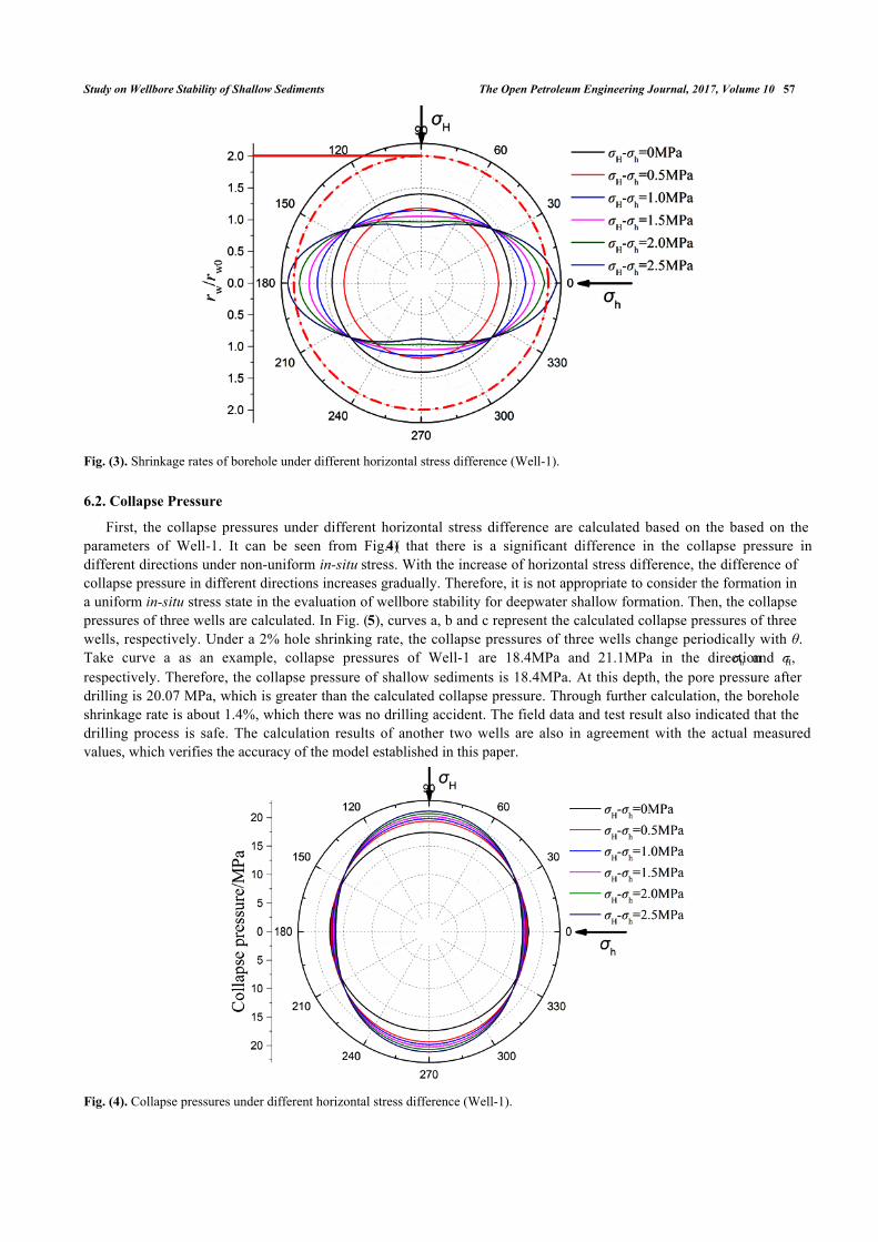
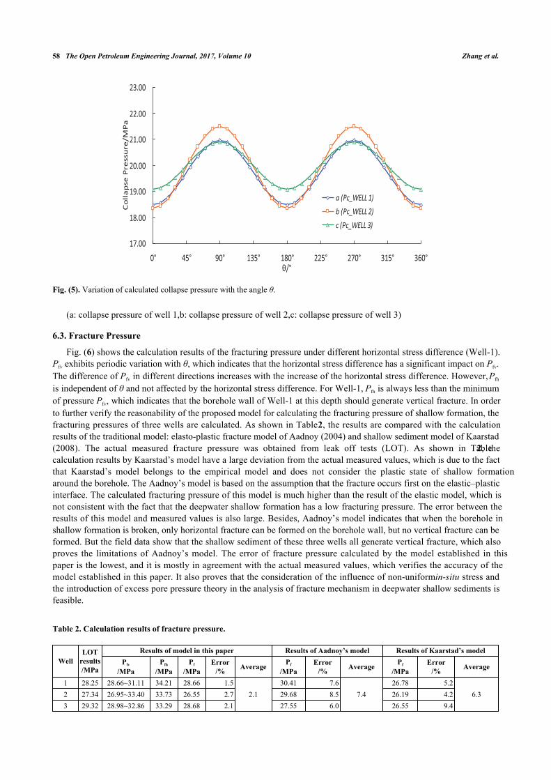
First, the collapse pressures under different horizontal stress difference are calculated based on the based on theparameters of Well-1. It can be seen from Fig. (4) that there is a significant difference in the collapse pressure indifferent directions under non-uniform in-situ stress. With the increase of horizontal stress difference, the difference ofcollapse pressure in different directions increases gradually. Therefore, it is not appropriate to consider the formation ina uniform in-situ stress state in the evaluation of wellbore stability for deepwater shallow formation. Then, the collapsepressures of three wells are calculated. In Fig. (5), curves a, b and c represent the calculated collapse pressures of threewells, respectively. Under a 2% hole shrinking rate, the collapse pressures of three wells change periodically with θ.Take curve a as an example, collapse pressures of Well-1 are 18.4MPa and 21.1MPa in the direction σh and σH,respectively. Therefore, the collapse pressure of shallow sediments is 18.4MPa. At this depth, the pore pressure afterdrilling is 20.07 MPa, which is greater than the calculated collapse pressure. Through further calculation, the boreholeshrinkage rate is about 1.4%, which there was no drilling accident. The field data and test result also indicated that thedrilling process is safe. The calculation results of another two wells are also in agreement with the actual measuredvalues, which verifies the accuracy of the model established in this paper.
Fig. (4). Collapse pressures under different horizontal stress difference (Well-1).
58 The Open Petroleum Engineering Journal, 2017, Volume 10 Zhang et al.
Fig. (5). Variation of calculated collapse pressure with the angle θ.
(a: collapse pressure of well 1,b: collapse pressure of well 2,c: collapse pressure of well 3)
6.3. Fracture Pressure
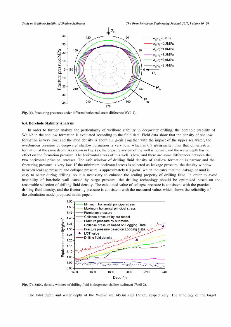
Fig. (6) shows the calculation results of the fracturing pressure under different horizontal stress difference (Well-1).Pfv exhibits periodic variation with θ, which indicates that the horizontal stress difference has a significant impact on Pfv.The difference of Pfv in different directions increases with the increase of the horizontal stress difference. However, Pfh
is independent of θ and not affected by the horizontal stress difference. For Well-1, Pfh is always less than the minimumof pressure Pfv, which indicates that the borehole wall of Well-1 at this depth should generate vertical fracture. In orderto further verify the reasonability of the proposed model for calculating the fracturing pressure of shallow formation, thefracturing pressures of three wells are calculated. As shown in Table 2, the results are compared with the calculationresults of the traditional model: elasto-plastic fracture model of Aadnoy (2004) and shallow sediment model of Kaarstad(2008). The actual measured fracture pressure was obtained from leak off tests (LOT). As shown in Table 2, thecalculation results by Kaarstad’s model have a large deviation from the actual measured values, which is due to the factthat Kaarstad’s model belongs to the empirical model and does not consider the plastic state of shallow formationaround the borehole. The Aadnoy’s model is based on the assumption that the fracture occurs first on the elastic–plasticinterface. The calculated fracturing pressure of this model is much higher than the result of the elastic model, which isnot consistent with the fact that the deepwater shallow formation has a low fracturing pressure. The error between theresults of this model and measured values is also large. Besides, Aadnoy’s model indicates that when the borehole inshallow formation is broken, only horizontal fracture can be formed on the borehole wall, but no vertical fracture can beformed. But the field data show that the shallow sediment of these three wells all generate vertical fracture, which alsoproves the limitations of Aadnoy’s model. The error of fracture pressure calculated by the model established in thispaper is the lowest, and it is mostly in agreement with the actual measured values, which verifies the accuracy of themodel established in this paper. It also proves that the consideration of the influence of non-uniform in-situ stress andthe introduction of excess pore pressure theory in the analysis of fracture mechanism in deepwater shallow sediments isfeasible.
Table 2. Calculation results of fracture pressure.
WellLOT
results/MPa
Results of model in this paper Results of Aadnoy’s model Results of Kaarstad’s modelPfv
/MPaPfh
/MPaPf
/MPaError
/% Average Pf
/MPaError
/% Average Pf
/MPaError
/% Average
1 28.25 28.66~31.11 34.21 28.66 1.52.1
30.41 7.67.4
26.78 5.26.32 27.34 26.95~33.40 33.73 26.55 2.7 29.68 8.5 26.19 4.2
3 29.32 28.98~32.86 33.29 28.68 2.1 27.55 6.0 26.55 9.4
17.00
18.00
19.00
20.00
21.00
22.00
23.00
0° 45° 90° 135° 180° 225° 270° 315° 360°θ/°
Co
lla
pse
Pre
ssu
re/M
Pa
a (Pc_WELL 1)b (Pc_WELL 2)c (Pc_WELL 3)
Study on Wellbore Stability of Shallow Sediments The Open Petroleum Engineering Journal, 2017, Volume 10 59
Fig. (6). Fracturing pressures under different horizontal stress difference(Well-1).
6.4. Borehole Stability Analysis
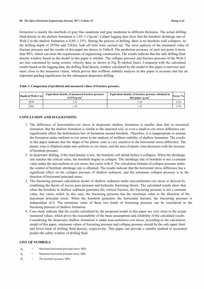
In order to further analyze the particularity of wellbore stability in deepwater drilling, the borehole stability ofWell-2 in the shallow formation is evaluated according to the field data. Field data show that the density of shallowformation is very low, and the mud density is about 1.1 g/cm3. Together with the impact of the upper sea water, theoverburden pressure of deepwater shallow formation is very low, which is 0.7 g/cm3 smaller than that of terrestrialformation at the same depth. As shown in Fig. (7), the pressure system of the well is normal, and the water depth has noeffect on the formation pressure. The horizontal stress of this well is low, and there are some differences between thetwo horizontal principal stresses. The safe window of drilling fluid density of shallow formation is narrow and thefracturing pressure is very low. If the minimum horizontal stress is selected as leakage pressure, the density windowbetween leakage pressure and collapse pressure is approximately 0.3 g/cm3, which indicates that the leakage of mud iseasy to occur during drilling, so it is necessary to enhance the sealing property of drilling fluid. In order to avoidinstability of borehole wall caused by surge pressure, the drilling technology should be optimized based on thereasonable selection of drilling fluid density. The calculated value of collapse pressure is consistent with the practicaldrilling fluid density, and the fracturing pressure is consistent with the measured value, which shows the reliability ofthe calculation model proposed in this paper.
Fig. (7). Safety density window of drilling fluid in deepwater shallow sediment (Well-2).
The total depth and water depth of the Well-2 are 3453m and 1367m, respectively. The lithology of the target
60 The Open Petroleum Engineering Journal, 2017, Volume 10 Zhang et al.
formation is mainly the interbeds of gray fine sandstone and gray mudstone in different thickness. The actual drillingfluid density in the shallow formation is 1.03~1.15g/cm3. Caliper logging data show that the borehole shrinkage rate ofWell-2 in the shallow formation is 0.68~1.35%. During the process of drilling, there is no borehole wall collapses. Atthe drilling depth of 2079m and 2382m, leak off tests were carried out. The error analysis of the measured value offracture pressure and the results of this paper are shown in Table 3. The prediction accuracy of each test point is morethan 90%, which can meet the requirements of engineering construction. The results indicate that the safe drilling fluiddensity window based on the model in this paper is reliable. The collapse pressure and fracture pressure of the Well-2are also calculated by using seismic velocity data, as shown in Fig. (7) (dotted lines). Compared with the calculatedresults based on the logging data, the drilling fluid density window calculated by the model in this paper is narrower andmore close to the measured values, which proves that wellbore stability analysis in this paper is accurate and has animportant guiding significance for the subsequent deepwater drilling.
Table 3. Comparison of predicted and measured values of fracture pressure.
Depth of Well-2 /m Equivalent density of measured fracture pressure(LOT)/g.cm-3
Equivalent density of fracture pressure obtained inthis paper /g.cm-3 Error /%
2079 1.21 1.24 2.5%2382 1.33 1.31 1.5%
CONCLUSION AND SUGGESTIONS
The difference of horizontal in-situ stress in deepwater shallow formation is smaller than that in terrestrial1.formation. But the shallow formation is similar to the saturated soil, so even a small in-situ stress difference cansignificantly affect the deformation law of formation around borehole. Therefore, it is inappropriate to assumethe formation under uniform in-situ stress in the analysis of wellbore stability of shallow formation. The resultsin this paper indicate that the shape of the plastic zone is very sensitive to the horizontal stress difference. Theplastic zone is elliptical under non-uniform in-situ stress, and the area of plastic zone decreases with the increaseof borehole pressure.In deepwater drilling, if the mud density is low, the borehole will shrink before it collapses. When the shrinkage2.rate reaches the critical value, the borehole begins to collapse. The shrinkage rate of borehole is not a constantvalue under the non-uniform in-situ stress, but varies with θ. The calculation formula of collapse pressure underthe control of borehole shrinkage rate is obtained. The results indicate that the horizontal stress difference has asignificant effect on the collapse pressure of shallow sediment, and the minimum collapse pressure is in thedirection of horizontal principal stress.The fracturing pressure calculation model of shallow sediment under non-uniform in-situ stress is derived by3.combining the theory of excess pore pressure and hydraulic fracturing theory. The calculated results show thatwhen the borehole in shallow sediment generates the vertical fracture, the fracturing pressure is not a constantvalue, but varies with θ. In this case, the fracturing pressure has the minimum value in the direction of themaximum principal stress. When the borehole generates the horizontal fracture, the fracturing pressure isindependent of θ. The minimum value of these two kinds of fracturing pressure can be considered as thefracturing pressure of shallow formation.Case study indicate that the results calculated by the proposed model in this paper are very close to the actual4.measured values, which prove the reasonability of the basic assumptions and reliability of the calculated results.Considering the deepwater shallow formation is under non-uniform in-situ stress, according to the calculationmodel of this paper, minimum values of fracturing pressure and collapse pressure should be the safe upper limitand lower limit of drilling fluid density, respectively. This paper can provide a reliable method to accuratelypredict the safety window of drilling fluid.
LIST OF SYMBOLS
σH = Maximum horizontal principal stress, MPa
σh = Minimum horizontal principal stress, MPa
Pw = The borehole pressure, MPa
Study on Wellbore Stability of Shallow Sediments The Open Petroleum Engineering Journal, 2017, Volume 10 61
rw0 = Bit radius during the drilling, mm
rw = Borehole radius after drilling, mm
rb = Distance elastic-plastic interface to the borehole center, mm
θ = Angle from the orientation of minimum horizontal principal stress, deg
σr = Radial stress on the wall of borehole
σθ = Tangential stress on the wall of borehole
C = Cohesion, MPa;
φ = Internal friction angle, deg
σ0 = Uniaxial compressive strength (UCS), MPa
εr = The radial strain
εθ = The tangential strain
u = Is the formation displacement
μb = Displacement on the elastic-plastic interface
μrb = Displacement on the elastic-plastic interface
ΔP = Excess pore pressure, MPa
β = Henkel’s pore pressure parameters, for saturated soil, β=1
A = Skempton’s pore pressure parameter under the effect of deviatoric stress
Δσ1 = Major principal stress increments
Δσ3 = Minor principal stress increments
Pp0 = In-situ pore pressure, MPa
Pc = Collapse pressure of shallow sedimentary formations, MPa
Pfv = Fracture pressure of vertical fracture, MPa
Pfh = Fracture pressure of horizontal fracture, MPa
Pf = Fracture pressure of shallow sedimentary formations, MPa
CONFLICT OF INTREST
The authors confirm that this article content has no conflict of interest.
ACKNOWLEDGEMENTS
This work was supported by the National Science and Technology Major Project of China (2016ZX05046004-004)and National Natural Science Foundation of China (No.51490650).
REFERENCES
[1] J. Shelton, J.R. Smith, and A. Gupta, "Experimental evaluation of separation methods for a riser dilution approach to dual density drilling",Journal of Energy Resources and Technology, vol. 133, no. 3, pp. 611-620, 2011.[http://dx.doi.org/10.1115/1.4004968]
[2] B.H. Yu, C.L. Yan, J.G. Deng, S.J. Liu, Q. Tan, and K. Xiao, "Evaluation and application of wellbore stability in deep water", Oil Drilling &Production Technology, vol. 33, no. 6, pp. 1-4, 2011.
[3] J. Dodson, T. Dodson, and V. Schmidt, "Gulf of Mexico ‘trouble time’ creates major drilling expenses: use of cost-effective technologiesneeded", Offshore, vol. 64, no. 1, pp. 46-48, 2004.
[4] W. Jeong-Yun, and S. Hadi, "An empirical correlation for compressibility of shallow depth clays in deepwater Gulf of Mexico", In: ASME2014 33rd International Conference on Ocean, Offshore and Arctic Engineering, 2014, p. V003T10A021.[http://dx.doi.org/10.1115/OMAE2014-24223]
[5] L.A.S. Rocha, P. Junqueira, and J.L. Roque, "Overcoming deep and ultra deepwater drilling challenges", In: Offshore Technology Conference,2003, p. OTC-15233-MS.[http://dx.doi.org/10.4043/15233-MS]
[6] A. Paknejad, J. Schubert, and M. Amani, "A new method to evaluate leak-off tests in shallow marine sediments (SMS)", In: SPE SaudiArabia Technical Symposium, 2007, p. SPE-110953-MS.[http://dx.doi.org/10.2118/110953-MS]
62 The Open Petroleum Engineering Journal, 2017, Volume 10 Zhang et al.
[7] R. Chhajlani, and Z.Q. Zheng, "Utilization of geomechanics for Medusa field development, deepwater gulf of Mexico", SPE AnnualTechnical Conference and Exhibition, 2002 SPE-77779-MS.[http://dx.doi.org/10.2118/77779-MS]
[8] L. Cui, Y. Abousleiman, A.H.D. Cheng, and J.C. Roegiers, "Time dependent failure analysis of inclined boreholes in fluid-saturatedformation", Journal of Energy Resources Technology, vol. 121, no. 1, pp. 31-39, 1999.[http://dx.doi.org/10.1115/1.2795057]
[9] A.M. Al-Ajmi, and M.H. Al-Harthy, "Probabilistic wellbore collapse analysis", Journal of Petroleum Science & Engineering, vol. 74, no. 3,pp. 171-177, 2010.[http://dx.doi.org/10.1016/j.petrol.2010.09.001]
[10] D.G. Ritter, and B. Grollimund, "Wellbore stability in the deepwater Bijupira & Salema fields, offshore Brazil-a probabilistic approach", In:Offshore Technology Conference, 2003, p. OTC-15205-MS.[http://dx.doi.org/10.4043/15205-MS]
[11] E. Kaarstad, and B.S. Aadnoy, "Fracture model for general off-shore applications", In: SPE Asia Pacific Oil & Gas Conference andExhibition, 2006, p. SPE-101178-MS.[http://dx.doi.org/10.2118/101178-MS]
[12] E. Kaarstad, and B.S. Aadnoy, "Improved prediction of shallow sediment fracturing for offshore applications", Spe Drilling & Completion,vol. 23, no. 2, pp. 88-92, 2008.[http://dx.doi.org/10.2118/101178-PA]
[13] C.L. Yan, J.G. Deng, and X.R. Lai, "Borehole stability analysis in deepwater shallow sediments", Journal of Energy Resources Technology,vol. 137, pp. 1-6, 2015.[http://dx.doi.org/10.1115/1.4027564]
[14] L.S. Zhang, X.Z. Yan, X.J. Yang, Z.L. Tian, and H.L. Yang, "An elastoplastic model of collapse pressure for deep coal seam drilling based onHoek–Brown criterion related to drilling fluid loss to reservoir", Journal of Petroleum Science and Engineering, vol. 134, pp. 205-213, 2015.[http://dx.doi.org/10.1016/j.petrol.2015.07.003]
[15] Y. Jin, M. Chen, and C. Wu, "Borehole stability prediction before drilling for formations under the second section in an exploration well",Petroleum Exploration and Development, vol. 35, no. 6, pp. 742-745, 2008.
[16] W.B. Bradley, "Mathematical concept—stress cloud can predict borehole failure", Oil & Gas Journal, vol. 77, no. 8, pp. 92-102, 1979.
[17] W.B. Bradley, "Failure of inclined boreholes", Journal of Energy Resources Technology, vol. 101, no. 4, pp. 232-240, 1979.[http://dx.doi.org/10.1115/1.3446925]
[18] F.L. Ning, "Research on Wellbore Stability in Gas Hydrae Formation", Ph.D thesis, China University of Geosciences, Beijing, China, 2005.
[19] Q.H. Sun, J.G. Deng, C.L. Yan, B.H. Wei, S.J. Liu, Z.L. Liu, and K. Xiao, "Calculation method for fracture pressure of deep sea shallowformation", Journal of Central South University (Science and Technology), vol. 46, no. 4, pp. 1402-1408, 2015.
[20] B.H. Yu, C.L. Yan, J.G. Deng, J.L. Zhou, S.J. Liu, and X.J. Xing, "Study and application of calculation model of safe drilling fluid densitywindow—A case study of AKPO Oil field, West Africa", China Offshore Oil and Gas, vol. 24, no. 2, pp. 58-60, 2012.
[21] B.S. Jiang, L. Yang, and L.P. Shi, "Stress analysis of cracked surrounding rock based on Hoek-Brown criterion", Chinese Journal of SolidMechanics, vol. 32, pp. 300-305, 2011.
[22] C.W. Wang, R.H. Wang, J.Y. Pu, R.D. Chen, S.Q. Zhong, and F.D. Li, "Problems existent in deepwater cementing and its solution", Drilling& Production Technology, vol. 29, no. 3, pp. 11-14, 2006.
[23] Y.R. Zhou, J.H. Wang, and S.Z. Li, "Static and cyclic behaviors of remoulded deepwater sediments of Liwan in South China Sea", MarineScience Bulletin, vol. 32, no. 5, pp. 521-526, 2013.
[24] Q. Tan, B.H. Wei, J.G. Deng, C.L. Yan, and K. Zhao, "Calculation method of drilling safety density window in deepwater oil and gas fields",Journal of Oil and Gas Technology, vol. 34, no. 10, pp. 98-104, 2012.
[25] Y. Jin, and M. Chen, "A new approach for controlling tight hole in salt formation", Chinese Journal of Rock Mechanics and Engineering, vol.19, pp. 1111-1114, 2000.
[26] D. Zhou, and A.K. Wojtanowicz, "Analysis of leak-off tests in shallow marine sediments", Journal of Energy Resources Technology, vol.124, no. 4, pp. 231-238, 2002.[http://dx.doi.org/10.1115/1.1506322]
[27] Z. Nie, B.R. Xia, L.Z. Zou, and J.G. Deng, "Modeling of wellbore stability for gas drilling", Natural Gas Industry, vol. 31, no. 6, pp. 71-76,2011.
[28] Q.H. Feng, Y.F. Cheng, and J.G. Zhang, "Elastic& plastic model for borehole stability and its apllication", Petroleum Drilling Techniques,vol. 28, no. 4, pp. 8-10, 2000.
[29] L.S. Zhang, X.Z. Yan, X.J. Yang, Z.L. Tian, and H.L. Yang, "Elasto-plastic analysis of collapse pressure for deep coal seam drilling based onHoek-Brown criterion", Journal of China Coal Society, vol. 38, no. 1, pp. 85-90, 2013.
[30] J.Q. Liu, "Research on the Mechanism of Wellbore Instability and Technical Methods in Baonan Area", Ph.D thesis, Xi'an Shiyou University,Xian, China, 2013.
Study on Wellbore Stability of Shallow Sediments The Open Petroleum Engineering Journal, 2017, Volume 10 63
[31] Y. Yang, G.H. Wu, L.Q. Tang, and J.Y. Yang, "Analysis of wellbore stability by the elasto-plastic finite deformation theory", Journal ofHarbin Engineering University, vol. 31, no. 11, pp. 1460-1464, 2010.
[32] A.A. Al-Karni, "Evaluation of shear strength of cohesionless soil due to excess pore water pressure", Arabian Journal of Geosciences, vol. 4,no. 7-8, pp. 1095-1101, 2011.[http://dx.doi.org/10.1007/s12517-009-0112-7]
[33] J. Lovisa, W.W. Read, and N. Sivakugan, "Calculating c(v) based on non-uniform initial excess pore pressure", Géotechnique, vol. 62, no. 8,pp. 741-748, 2012.[http://dx.doi.org/10.1680/geot.11.P.055]
[34] A.W. Skempton, "The pore-pressure coefficients A and B", Géotechnique, vol. 4, no. 4, pp. 143-147, 1954.[http://dx.doi.org/10.1680/geot.1954.4.4.143]
[35] D.J. Henkel, "The relationship between the strength, pore waterpressure and volume change characteristics of saturated clays", Géotechnique,vol. 9, pp. 119-135, 1959.[http://dx.doi.org/10.1680/geot.1959.9.3.119]
[36] J.H. Qian, and Z.Z. Yin, Geotechnical Principles and Calculation, China Water Resource and Hydropower Press: Beijing, China, 1994.
[37] X.G. Wen, X. Zhang, and J. Zhou, "Influencing factors about pore pressure generated for clay under complex stress path", Chinese Journal ofGeotechnical Engineering., vol. 32, no. 11, pp. 1709-1716, 2010.
[38] B.S. Aadnoy, and M. Belayneh, "Elasto-plastic fracturing model for wellbore stability using non-penetrating fluids", Journal of PetroleumScience & Engineering, vol. 45, no. 3-4, pp. 179-192, 2004.[http://dx.doi.org/10.1016/j.petrol.2004.07.006]
[39] E. Fjær, R.M. Holt, P. Horsrud, and A.M. Raaen, Petroleum Related Rock Mechanics, 2nd ed. Elsevier, Amsterdam: The Netherlands, 2008.
[40] R.T. Ewy, "Yield and closure of directional and horizontal wells", International journal of rock mechanics and mining sciences, vol. 30, no. 7,pp. 1061-1067, 1993.[http://dx.doi.org/10.1016/0148-9062(93)90072-L]
© 2017 Zhang et al.
This is an open access article distributed under the terms of the Creative Commons Attribution 4.0 International Public License (CC-BY 4.0), acopy of which is available at: https://creativecommons.org/licenses/by/4.0/legalcode. This license permits unrestricted use, distribution, andreproduction in any medium, provided the original author and source are credited.