the operation of the gccia hvdc project and its potential … · the gcc interconnection is the...
TRANSCRIPT

The Operation of the GCCIA HVDC Project and
Its Potential Impacts on the Electric Power
Systems of the Region
Tawfiq M. Aljohani University of Southern California, Los Angeles, California, USA
Email: [email protected]
Abdullah M. Alzahrani Saudi Aramco Consulting Services Department, Dhahran, Saudi Arabia
Email: [email protected]
Abstract—The Gulf Cooperation Council Interconnection
Authority (GCCIA) has constructed and commissioned a
400kV interconnection grid between Kuwait, Saudi Arabia,
Bahrain, Qatar and United Arab of Emirates (UAE), that
includes 900 km of overhead lines, seven 400kV substations,
a 1800MW three-pole back-to-back HVDC converter station
and a submarine cable to Bahrain. This paper summarizes
the design features of the GCCIA Back-to-Back HVDC
station, illustrates both the technical considerations and
physical characteristics of the project, and highlights the
operational experience since its operation in 2009. Also, the
paper provides some environmental aspects and personal
recommendations, and sum up with illustrative conclusion
over the covered topics.
Index Terms—high-voltage direct-current transmission,
interconnection, GCCIA, back-to-back HVDC, power
system operation, grid connectivity, power system
converters
I. INTRODUCTION TO GCCIA
A high level grid interconnection among the Gulf
Cooperation Council (GCC) states was recognized
beneficial to address the need of economic power transfer
and achieve higher reliability and sustainable
transmission services between the Gulf States. Eventually,
the Gulf Cooperation Council Interconnection Authority
(GCCIA) completed a 400kV Interconnection grid
between six Gulf States members which are: Saudi
Arabia, Kuwait, Qatar, Bahrain, United Arab Emirates
(UAE) and Oman. Since Saudi Arabia’s network operates
at 60 Hz and the other Gulf States are at 50Hz,
synchronous AC interconnection was not possible.
Therefore, HVDC station was the only solution to
interconnect the power grids of the member states [1], [2].
The project established three Back-to-Back HVDC each
rated 600MW (1800MW total) convertor stations
between the interconnected 50Hz 400kV systems of
Kuwait, Bahrain, Qatar, UAE and Oman on one side, and
Manuscript received September 25, 2013; revised January 15, 2014.
the 60Hz 380kV system of Saudi Arabia on the other side.
The HVDC station was constructed in Saudi Arabia
connecting GCCIA 400kV 50 Hz Al-Fadhili substation to
Saudi Electricity Company (SEC) 380kV 60Hz Al-
Fadhili substation [1], [3], [4].
The GCCIA HVDC converter station was not only the
biggest Back-to-Back station in the world (1800MW), but
also introduced a unique feature which permits the
sharing of reserves between the 60Hz and 50Hz power
systems. The planning studies that were carried out to
satisfy the GCC need for the interconnection of the
independent GCC grids were based on the following
objectives:
Interconnect the member states’ electrical power
networks by providing the necessary investments
for power sharing to anticipate power generation
loss in emergency situations.
Reduce the spinning reserves of each member
state.
Improve the economic power system efficiency
throughout the member states.
Provide cost-effective power sharing capabilities
among the member states and strengthen
collective electrical supply reliability.
II. PHYSICAL CHARACTERISTICS OF THE PROJECT
Figure 1. The geographical routes and layout of the GCC interconnection
207
International Journal of Electronics and Electrical Engineering Vol. 2, No. 3, September, 2014
©2014 Engineering and Technology Publishingdoi: 10.12720/ijeee.2.3.207-213

The GCC Interconnection is the biggest back-to-back
HVDC station in the world with capacity of (3×600MW)
1800MW and it is the first of its kind in the region. The
GCC HVDC main station is located in Saudi Arabia at
Al-fadhili which is a desert area known for its sand
storms and high temperatures during summer that could
reach about +125°F. This extreme weather condition has
enforced unique design for the station. Fig. 1 shows the
geographical routes and layout of the GCC
interconnection.
The project was implemented in three phases and has
been divided into several work packages which are:
substations, back-to-back HVDC converter station,
submarine cable, overhead transmission line and a control
center. The purpose is to enable a wide participation by
international contractors in the implementation of the
GCC project in an efficient and economic manner [4], [5].
Table I shows the work packages and the assigned
contractors.
TABLE I. PROJECT CONTRACTORS
Work Package Contractor
Substations ABB
HVDC Station Areva-Congelex
Overhed Transmission Line NCC & MEEDCO
Cable Prysmain – Nexans
Control Areva-Congelex
Supervision SNC-Lavalin
III. TECHNICAL CHARACTERISTICS OF THE PROJECT
The GCC HVDC project is a 400kV interconnection
grid that includes 3300km (2100 mile) of overhead lines,
seven 400kV substations, and 37km (23mi) of submarine
cable to Bahrain. It allows power exchanges between
Gulf States as shown in Fig. 2. Saudi Arabia and Kuwait
each is able to export or import up to 1,200MW from the
grid, while Bahrain, Qatar and UAE are able to trade
600MW, 750MW and 900MW, respectively. Oman has
the lowest interconnector capacity at 400MW [6], [7].
Figure 2. GCC interconnection configuration
The GCC converter station allows reserve sharing
between the electrical power systems of participating
member states. Also, it permits power transfer between
the member states when such transfer has economic
benefits. To achieve effective reserve sharing, the GCC
HVDC project has implemented the Dynamic Reserve
Power Sharing (DRPS) Control scheme which ensures
that up to 1200MW of active power will be able to be
transferred from 50Hz to 60Hz systems and vice versa
with sufficient speed of response and accuracy of control
to stabilize the interconnected systems following the
established critical loss of generation event within either
system. The HVDC converter facility also allows
economic interchange of up to 1200MW of active power
between the systems in either direction provided that the
ability to effectively share reserve is not compromised. In
order to ensure the availability of 1200MW of inter-
system real power transfer capability, three independent
600MW back-to-back converters (poles) are installed and
commissioned in 2009. Each pole is required to meet this
power transfer level under specified system operating and
environmental conditions. The key electrical parameters
for dimensioning of the station are summarized in Table
II [7].
TABLE II. HVDC STATION RATING PARAMETERS
Parameter 60Hz 50Hz
Nominal voltage 380kV 400kV
Max. continuous voltage 399kV 420kV
Min. continuous voltage 361kV 380kV
Max. 30 min voltage 418kV
Min. 30 min voltage 342kV
lighting impulse withstand
level 1425kV 1300kV
switching impulse withstand
level 1050kV 1050kV
Continuous frequency 60 ± 0.5% 50 ± 0.5%
30 min frequency 60 ± 1.0% 50 ± 1.0%
10 sec frequency 60 ± 2.5% 50 ± 2.5%
0.5 sec frequency 60 ± 5.0% 50 ± 5.0%
Each 600MW pole is identical and fully rated for
power flow in either direction. This power rating is
available under all of the system operating conditions
listed in Table II. Each pole is designed to operate from a
minimum power of 60MW (10%) to a maximum
continuous overload of 660MW (110%). The latter figure
is achieved when all transformer and valve cooling
systems are available. These figures can be achieved over
the complete range of system conditions listed in Table II.
Continuous overload in excess of 660MW can be
achieved at lower ambient temperatures. Short time
overload capability, from 5 minutes to 30 minutes, is also
available, the actual capability being dependent upon the
prior operating regime of the converter station.
The GCC HVDC station consists of the following
major components:
A. AC Switchyard with Harmonic Filters
HVDC converters consume reactive power and also
generate harmonic currents. The AC systems have only
limited capacity to deliver or receive reactive power and
limited tolerance to harmonic currents. Harmonic filters
are provided with all HVDC schemes to approximately
balance the reactive power consumed by the converters as
208
International Journal of Electronics and Electrical Engineering Vol. 2, No. 3, September, 2014
©2014 Engineering and Technology Publishing

they are capacitive at fundamental frequency and they
reduce the harmonic distortion to acceptable limits. For
the GCC project, these filters are switched automatically
using Alstom Grid dead-tank circuit breakers, dis-
connectors and earth switches. As the converters generate
high frequency conducted harmonics, PLC filters were
added to block these harmonic currents from interfering
with power line carrier communication in the AC
networks. The switchyard is connected to the nearby GIS
substations by underground 400 kV class XPLE cable.
Table III shows the HVDC Filter ratings:
TABLE III. HVDC FILTER RATINGS
Converter End
Frequency/Voltage Hz/kV
Number of
Elements
Individual
Elements size (MVAr)
Total
MVAr per converter
50Hz/400 kV 2 130 397
1 137
60Hz/380 kV 2 180 360
B. Converting Transformers
Converting transformers (shown in Fig. 3) provide the
galvanic isolation between the AC and DC systems and
limitation of fault currents through the thyristor valves.
Twelve transformers were supplied in total for this
project consisting of four HVDC converter transformers
for each of the three poles. Each pole is comprised of the
following ratings: 385MVA, 380/97kV, 60Hz,
Y/Y385MVA, 380/97kV, 60Hz, Y/Delta 380MVA,
400/96kV, 50Hz, Y/Y380MVA, 400/96kV, 50Hz,
Y/Delta.
Figure 3. Converting transformer
C. Thyristor Valves and Controls
Each pole is arranged in pair of 12-pulse thyristor
Graetz bridges per side, fed from two separate Y/Y and
Y/Delta transformers. The thyristor valves are Alstom
Grid H400 series valves which are rated at 8.5kV and
have 125mm in diameter. Table IV shows the converter
ratings.
TABLE IV. CONVERTER RATINGS
Power (MW) DC link voltage (kv) DC link current (A)
616 222 2776
The converter structure as follow:
12 thyristors per module, 3 modules in series per
phase
The 4 valves associated with each phase are
mounted in a “quadrivalve” structure
3 “quadrivalves” create the 12 pulse bridges per
converter
Valves suspended from ceiling
HVDC converters need to be installed in a controlled
environment with low levels of dust (converters have a
tendency to act as an electrostatic precipitator and to
accumulate dust on insulating surfaces). For this reason,
the valves are installed in a “Valve Hall” with controlled
temperature, humidity and dust levels and with a slight
over-pressure to minimize dust ingress. These factors
were particularly important on this project which,
because of its desert location, is prone to high levels of
external dust. The valve hall contains not only the valves
but all equipment exposed to DC voltages. The only
equipment located outside is AC equipment which is
much less vulnerable to dust accumulation.
Each converter pole has a duplicated Alstom Grid
series V converter control and protection system to give
the necessary power transfer control and provide
protection to the converters and DC circuits. An overall
duplicated series V master control with an integrated
Human Machine Interface (HMI) allocates the required
power to each of the poles and in addition interfaces to
the GCC Interconnector Control Centre (ICC). Control
can either be in economic power transfer to permit
trading of power between regions or when necessary in
Dynamic Reserve Power Sharing (DRPS) mode to allow
very rapid support of a region suffering loss of power
generation. Master control also controls the reactive
power exchanged between the converter station and the
AC systems by switching harmonic filters and by
controlling the thyristor triggering angles. Conventional
protection is provided for the converter transformers,
harmonic filters, bus bars and power cables. A transient
fault recorder system is also provided [6], [7].
D. Cooling System
The very high ambient temperature on this project
posed a significant challenge. Because the temperature of
the valves’ active part (the silicon in the thyristors) needs
to be limited to 195°F, the water-cooling plant required
higher coolant flow rates than a standard HVDC link.
This required the largest water-cooling plant ever built
for an HVDC installation.
Each one of the back-to-back converters has a single
circuit valve cooling system to cool 6 quadri-valve
assemblies. The valves are liquid cooled with 100% De-
ionized Water. Due to the maximum outdoor ambient air
temperature of 130°F and +40°F allowance for the heat
exchanger, the maximum coolant inlet temperature to the
valves in service is 140°F. Because of the very high
maximum outdoor ambient temperature, it was necessary
to use an efficient thyristor cooling technique, which is
the parallel arrangement. The parallel cooling
arrangement has 7 coolant paths and it directly provides
209
International Journal of Electronics and Electrical Engineering Vol. 2, No. 3, September, 2014
©2014 Engineering and Technology Publishing

each thyristor heat sink with coolant at the inlet
temperature to the valve.
IV. ECONOMICS OF THE PROJECT
The capital cost of the three phases of the project is
US$1.1 billion, US$300 million and US$137 million,
respectively. Also, it was agreed among the Gulf States to
share the costs of the Interconnection in proportion to the
reserve capacity savings as per Table V.
TABLE V. COST SHARING OF THE PROJECT
Country Phase I Phase I & III
Kuwait 33.8% 33.8%
Saudi Arabia 40.0% 31.6%
Bahrain 11.4% 9.0%
Qatar 14.8% 11.7%
UAE - 15.4%
Oman - 5.6%
The economic evaluation of the Project showed that
the benefit to cost ratio for Phase I of the Project is of the
order of 1.5 and that the payback period for the
investment is less than four years. Given the small
incremental cost of Phase III it is evident that
implementation of Phase III would further improve the
attractiveness of the Project. Thus the analysis re-
confirmed the economic viability of the Project.
Figure 4. Project benefits and costs
Fig. 4 shows that upon the completion of phase 3 of
the project, the cost saving rate of return after three years
of operation is $3.35 billion [7], [8].
V. OPERATION OF THE GCCIA PROJECT
A. Phases of the project
The HVDC interconnection of GCCIA was
constructed in three phases:
Phase I: the interconnection of the northern part of the
project. Saudi Arabia, Qatar, Kuwait and Bahrain had
been interconnected by HVDC back-to-back converter
facility, which also include:
A double-circuit 400kV, 50Hz line from Al-Zour
substation (Kuwait) to Ghunan substation (Saudi
Arabia) with an intermediate connection at Al-
Fadhili substation (Saudi Arabia).
A double-circuit 400kV, 50Hz comprising
overhead lines and AC submarine cable from
Ghunan substation to Al-Jasra (Bahrain).
A double-circuit 400kV, 50Hz line from Ghunan
substation to Salwa substation (Saudi Arabia).
A double-circuit 400kV, 50Hz line from Salwa
substation to Doha South substation (Qatar).
An Interconnection Control Center (ICC) located at Ghunan substation in Saudi Arabia.
Phase II: the work on phase two had been constructed
in parallel in separate way from phase I. This phase
concerned the interconnection of UAE and Oman
national grids. It should be noticed that the
interconnection of UAE internal grids had been finished
earlier and wasn’t involved as a part of GCCIA project.
Phase III: phase three was the jointing point of the
two phases; the interconnection of the northern and
southern parts of the project together to form GCCIA
HVDC interconnected network.
A double-circuit 400kV, 50Hz line from Salwa
substation to Quwafiti substation (UAE).
A double-circuit and a single 200kV, 50Hz line from Al-Quhah substation (UAE) to Al-Wasset
substation (Oman).
Fig. 2 shows the block diagram of the three phases of
the project.
To control and monitor the operation of the project
effectively, GCCIA established a new interconnector
control center equipped with supervisory control and data
acquisition (SCADA) and energy management system
(EMS) facilities in Ghunan, Saudi Arabia.
B. Operational Studies
In addition to conducting studies during the feasibility
and planning stages of phase I, the GCCIA commissioned
operational studies during the final construction stage of
the GCC interconnection, prior to commissioning the
interconnecting transmission lines. The responsibility of
the planning and operational studies in the final stages of
the project, before energization and synchronization, was
done by RTE (Tractable Engineering and Elia). The
studies work entailed various workshops, attended by
GCCIA, the consultant consortium and representatives
from the operations team, as well as visits to European
control centers. The reliability of GCCIA interconnection
has been a great interest since the beginning of the project.
To ensure the flexibility of the power transfer, high and
new operational standard were implemented.
In order to address collective electricity needs and
achieve higher reliability and sustainable transmission
services of the GCCIA, a high level grid interconnection
amongst the states members was seen beneficial.
However, the difference in the operating frequencies
between Saudi Arabia’s 60 Hz system and its neighboring
states (Kuwait, Qatar, Bahrain, UAE and Oman) which
operate at 50Hz. Thus, an idea of having AC
interconnection was fundamentally excluded. The
solution came in installing HVDC back-to-back system
(1,800MW) converter station to connect the two
frequency systems. The HVDC station was constructed in
210
International Journal of Electronics and Electrical Engineering Vol. 2, No. 3, September, 2014
©2014 Engineering and Technology Publishing

Saudi Arabia connecting GCCIA 400kV 50Hz Al-Fadhili
substation to SEC 380kV 60Hz Al-Fadhili substation. To
ensure reliability of the system, three poles were installed
in the converter facility; each one would have the ability
to transfer up to 600 MW, where the third one is placed in
case of emergency mainly [8], [9].
C. Modes of Operation
The main objective of the control scheme in HVDC is
to perform the following:
To provide effective reserve power sharing
between the electrical power systems of
participating Member States.
To be able to be transfer 1200MW between the
50Hz to 60Hz systems fast enough to stabilize the
interconnected systems following a critical loss
of generation within either system through
“Dynamic Reserve Power Sharing” (DRPS), as
this term is going to ber introduced shortly in this
report.
To permit up to 1200MW of economic active
power transfer between the Member States.
In order to satisfy the objectives highlighted above, the
GCCIA HVDC was designed for three modes of
operations as follows:
Hot Standby Mode: the Poles are kept energized
from the AC (50Hz and 60Hz) grid, and, not
scheduled for any power transfer and not activated
for Dynamic mode of emergency sharing.
Economic Transfer (ET) Mode: under this mode
of operations, up to 1200MW of active power
transfers between two frequency systems can be
scheduled and implemented.
Dynamic Reserve Power Sharing (DRPS) Mode: this mode of operations has contributed to the fact
that GCCIA is a unique project; in this mode,
power transfer is activated to achieve dynamic
stability in either the 50 or 60Hz systems. The
DRPS system is being used for the first time in the
world in the GCCIA Project.
The HVDC converter station established at Al Fadhili
in Saudi Arabia was not only the biggest Back-to-Back
station in the world (3×600MW), but also introduced a
unique feature which permits the sharing of reserves
between the 60Hz and 50Hz systems The planning
studies that were carried out to satisfy the GCC need for
the interconnection of the independent GCC grids were
based on the need to provide mutual support in the event
of loss of generation in one network, permitting sharing
and effectively reduction of individual reserve levels
without compromising reliability. This mainly required
rapid and automatic response to loss of generation in any
country and the ability to rapidly change the direction of
power flow to provide the necessary system dynamic
support, through innovative control strategies for
automatic reserve sharing.
D. Load Shedding
Harmonization of under-frequency load shedding
(UFLS) is concerned with the high imbalance in active
power as a result of sudden loss of generation, leading to
a drop in frequency. This frequency drop can be corrected
by suitable automatic load-shedding schemes. All
member states had such schemes in place, but the
interconnection of separate power systems required a
harmonization of the existing UFLS schemes and the
definition of common rules to be followed by each
member state. When different power systems are
interconnected, the solidarity principle automatically
becomes the rule: The load is shed not only in the area
where the imbalance occurs but also in the interconnected
systems. This harmonization is required to minimize the
shed load and fairly share the contribution of each
member state. Two rules were recommended for the
UFLS harmonization of the GCC system:
The first UFLS threshold for the 50-Hz side
(Qatar, Bahrain and Kuwait) is 49.3Hz.
The first UFLS threshold of the 60-Hz side
(Saudi Arabia) is set to 59.2Hz to keep a similar
frequency range for the primary frequency
control on both sides of the HVDC connections.
No more than 200MHz between two UFLS stages.
VI. ENVIRONMENTAL ASPECTS
One of the main challenges that faced the project is the
environmental nature of the gulf area. The main
converting station is placed in the heart of the desert in a
very hot, dry weather with ambient temperature
exceeding 125F. Due to the fact that the temperature of
the valves’ active part (made from silicon) are required to
have a temperature limits up to 90°C, the water-cooling
plant required higher coolant flow rates than a standard
HVDC link. Thus, the cooling pipe arrangement within
the valve was changed to a parallel arrangement to
increase the total flow rate into the converter. This leads
to the construction of the largest cooling system for an
HVDC project ever [9].
Since the converter facility would be prone to high
level of external dust and sand storms, the valves were
installed in an air-conditioned room with heavy filters to
insure the quality of the air from such particles.
A. Impacts of the Environment on the Project
Operation
Since 2009 and up to now, many incidents have been
occurred due to the severe weather condition which
released alarms that sometimes caused non availability of
the poles.
Transformer fan failure, tap-changer out of
step and invalid tap code: the recurrence of the
sandstorms in Saudi Arabia has resulted in usual
occurrence of “Pole not ready” due to failure of
fans, tap changer out of step, and invalid tap code
caused by dust ingress into circuit contacts.
Cooling plant alarms: extreme outdoor ambient
temperatures in summer and winter causes alarms
related to temperature of the Valve cooling system
inlet and condensation temperature on thyristor
valve cooling that lead to tripping of Pole in some
cases. Many tests are being conducted in the
211
International Journal of Electronics and Electrical Engineering Vol. 2, No. 3, September, 2014
©2014 Engineering and Technology Publishing
moment by the manufacturer in order overcome
the problem.
Valve Hall Ac Disturbance: Alarms often
received related to dust causing failure of the
HVAC in the Valve hall and other sensitive
equipment.
VII. POTENTIAL IMPACTS ON THE POWER SYSTEMS OF
THE REGION
A. Regional Interconnectivity
There are much great potential that can be emerged by
the interconnection of GCCIA with many regional grids
which would result in successful cooperation in the area
of electricity trade [9, 10]. Such targeted interconnections
are as follow:
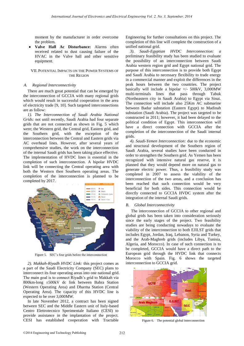
1). The Interconnection of Saudi Arabia National
Grids: not until recently, Saudi Arabia had four separate
grids that are not connected as shown in Fig. 5 which
were; the Western grid, the Central grid, Eastern grid, and
the Southern grid, with the exception of the
interconnection between the Central and Eastern grids via
AC overhead lines. However, after several years of
comprehensive studies, the work on the interconnection
of the internal Saudi grids has been taking place effective.
The implementation of HVDC lines is essential in the
completion of such interconnection. A bipolar HVDC
link will be connecting the Central operating area with
both the Western then Southern operating areas. The
completion of the interconnection is planned to be
completed by 2017.
Figure 5. SEC’s four grids before the interconnection
2). Makkah-Riyadh HVDC Link: this project comes as
a part of the Saudi Electricity Company (SEC) plans to
interconnect its four operating areas into one national grid.
The main goal is to connect Riyadh’s grid to Makkah via
800km-long ±500kV dc link between Bahra Station
(Western Operating Area) and Dharma Station (Central
Operating Area). The capacity of this HVDC line is
expected to be over 3,000MW.
In late November 2012, a contract has been signed
between SEC and the Middle Eastern unit of Italy-based
Centro Elettrotecnico Sperimentale Italiano (CESI) to
provide assistance in the implantation of the project.
CESI has established cooperation with Tractable
Engineering for further consultations on this project. The
completion of this line will complete the construction of a
unified national grid.
3). Saudi-Egyptian HVDC Interconnection: a
preliminary feasibility study has been studied to evaluate
the possibility of an interconnection between Saudi
Arabia western region grid and Egypt national grid. The
purpose of this interconnection is to provide both Egypt
and Saudi Arabia to necessary flexibility to trade energy
in a commercial manner and exploit the differences in the
peak hours between the two countries. The project
basically will include a bipolar +/- 500kV, 3,000MW
multi-terminals lines that pass through Tabuk
(Northeastern city in Saudi Arabia) to Egypt via Sinai.
The connection will include also 25Km AC submarine
between Badur substation (Eastern Egypt) to Madinah
substation (Saudi Arabia). The project was targeted to be
constructed in 2011; however, it had been delayed to the
political condition of Egypt. This interconnection will
have a direct connection with GCCIA after the
completion of the interconnection of the Saudi internal
grids.
4). Saudi-Yemen Interconnection: due to the economic
and structural development of the Southern region of
Saudi Arabia, several studies have been conducted in
order to strengthen the Southern grid. As Yemen has been
recognized with intensive natural gas reserve, it is
planned that they would depend more on natural gas to
generate electric power. Thus, a feasibility study was
completed in 2007 to assess the viability of the
interconnection of the two areas, and a conclusion has
been reached that such connection would be very
beneficial for both sides. This connection would be
directly connected to GCCIA HVDC system after the
integration of the internal Saudi grids.
B. Global Interconnectivity
The interconnection of GCCIA to other regional and
global grids has been taken into consideration seriously
since the early stages of the project. Two feasibility
studies are being conducting nowadays to evaluate the
viability of the interconnection to both EJILST grids that
includes Egypt, Jordan, Iraq, Lebanon, Syria and Turkey,
and the Arab-Maghreb grids (includes Libya, Tunisia,
Algeria, and Morocco). In case of such connection is to
be completed, GCCIA would have a direct path to the
European grid through the HVDC link that connects
Morocco with Spain. Fig. 6 shows the targeted
interconnection to GCCIA grid.
Figure 6. The potential global interconnection
212
International Journal of Electronics and Electrical Engineering Vol. 2, No. 3, September, 2014
©2014 Engineering and Technology Publishing

C. Recommendation and Suggestions
The Gulf area is currently promising many renewable
energy projects in the near future. For instance, Saudi
Arabia has targeted to build concentrated solar systems,
while UAE opened in 2009 the largest solar station in the
world, Masdar City. Thus, we recommend that by
integrating interconnection between these projects and
GCCIA, a better and more reliable operation would result.
Also the fiber optics system associated with Al-fadili
stations is a very developed one, the largest for an HVDC
system, thus we believe the telecommunication
companies could ask for permission to use it which would
allow benefits for the both sides.
VIII. CONCLUSION
The interconnections of the six members of the
Arabian Gulf countries have been so far a very successful
one and more than 250 loss-of-generation incidents have
been resolved efficiently [11]. The idea of this project
came before 30 years ago when multiple efforts had
dreamed of having one interconnected network for all the
gulf area countries. Yet after three feasibility studies, the
project did not get the final approval until 20 years after
the idea was firstly suggested. In this project, we tried to
go cover all the aspects of GCCIA as a project in total.
We started with a quick introduction on the project,
followed by some extensive details on the physical
characteristic and technical considerations that clearly
illustrate the basic components of the project with the
ratings of the equipment used. After that, we briefly
discussed the economics of the project, which is mainly a
governmental-paid, so that the participated utilities main
job was to focus on other technical and operational issues,
away from financial ones. The operation of the project
have been clearly described along with the features that
made GCCIA a unique project, such as the use of DRP
control scheme for the first time in the world. In addition,
some related topics to the project like defining the modes
of operation, the load shedding followed in the project
have been discussed for a better clarification of the nature
of work. Proposed future plans of the project, which
includes regional interconnection with Yemen, Egypt,
would be completed successfully soon after the
completion of the Saudi internal grid, which will give
these countries a direct connection to GCCIA. Also,
feasibility studies have been conducted to evaluate the
benefits of a global interconnection between Europe and
the mediterranian region [12]. The impacts that would
result from implementing such large interconnection,
which aim basicly to interconnect different continents,
will be used hopefully to exploit the difference in peak
load times and weather condition globally to reduce the
overall power generation and to enhance the operation
against the faults by taking the advantage of the
capability of HVDC networks to operate more effecient
against regular problems that face the Interconnected AC
systems [13]. Finally, the paper concluded with
suggestion and recommendation for this project based on
some of what they had captured in this course. There is
no doubts that GCCIA has been an effective project so far,
and it have contributed sufficiently in the reliable,
economic operation of the electric grid in the gulf area,
which is known for having its load demand increasing
significantly each year, and soon this project would be
ready to play a major role in connecting both the western
and eastern parts of the world, hopefully someday in the
near future.
REFERENCES [1] H. Al-Asaad. GCC. The backbone of power reform. GCCIA
[Online]. Available: http://www.gccia.com.sa
[2] H. Al-Asaad and A. A. Ebrahim, “GCC power grid: Benefits and
beyond,” OGEL, vol. 6, no. 3, 2008.
[3] Alawaji and H. Saleh, “An update on the GCC and pan-Arab
interconnection grids,” Jeddah Water and Power Forum, November 12-14, 2005.
[4] Al-Mohaisen and Adnan Ibrahim, Electricity Network Connectivity between the GCC Countries, GCCIA.
[5] Al-Mohaisen, Adnan, et al., “Progress report on the GCC
electricity grid interconnection in the middle East,” Power Engineering Society, Panel Session Tampa, 24-28 June 2007.
[6] Al-Shaikh and Mohamed, “The GCC interconnection grid,” in Proc. 7th Power Transmission and Distribution Forum, Bahrain,
28-30 October 2007.
[7] M. Al-Shaikh and A. Al-Ebrahim, “GCCIA HVDC: Unique design features to meet specific operational requirements,”
Alkhaleej Electricity, no. 19, 2011. [8] Al-Shaikh, Mohamed, and Al-Ebrahim, Ahmed, “GCCIA HVDC:
Unique design features to meet specific operational
requirements,” Alkhaleej Magazeen, no. 19, 2011. [9] F. Hamish, and H. K. Al-Asaad, “Engaging in cross-border
power exchange and trade via the Arab gulf states power grid,”
The Electricity Journal, December 2008.
[10] M. Keith, Muhammad Akhtar, and N. Fakhar, “The prospects for
electricity trade between the GCC countrie,” in Proc. Power Transmission & Distribution Forum, Dubai, 6-7 March 2005.
[11] GCC Grid progress reports. GCCIA, 2004-2010. [12] Union of the Electricity Industry. (2003). Mediterranean
Interconnection: State of the Art. [Online]. Available:
www.eurelectric.org/PublicDoc.asp?ID=23889 [13] C. Kim, V. K. Sood, G. Jang, S. Lim, and S. Lee, HVDC
Transmission: Power Conversion Applications in Power Systems, John Wiley & sons (Asia) Pte Ltd, Singapore, 2009.
Tawfiq M. Aljohani received his B.SC degree in electrical engineering
in 2009 from King AbdulAziz University, Jeddah, Saudi Arabia. He is currently a master student in University of Southern California, Los
Angeles, California, where he is currently conducting his thesis on the
applications of smart grid in improving the reliability of the power system distribution. His research interests include deterministic and
probabilistic power system planning and reliability, power system operation and security, renewable energy and smart grid applications.
Abdullah Alzahrani earned a Bachelor of Science degree in Electrical
Engineering from King Fahad University of Petroleum and Minerals in 2006. Also, he has completed Master of Science degree in Electrical
Engineering from University of Southern California in 2012. Currently
he is working with Saudi Aramco Company specializing in power systems studies and analysis. Abdullah has research interest in HVDC,
renewable energy integrations and power systems analysis. He is a member in IEEE since 2005.
213
International Journal of Electronics and Electrical Engineering Vol. 2, No. 3, September, 2014
©2014 Engineering and Technology Publishing