the original bending · pdf filethe original bending brace objectives 2 ... brace fitting and...
TRANSCRIPT

OBB
THE ORIGINAL
BENDING
BRACE
NIGHTTIME MANAGEMENT
OF ADOLESCENT IDIOPATHIC
SCOLIOSIS

Re-introducing the
C. Ralph Hooper, Jr., CPO Until now, C. Ralph Hooper, Jr., CPO maintained a
license agreement with Hanger, Inc. for production.
This relationship has reached its end and Mr.
Hooper will no longer be associated with Hanger.
All responsibilities for designs by C. Ralph Hooper,
Jr., CPO will be done under the name Original
Bending Brace, LLC. Manufacturing and design will
be coordinated by The Bending Brace Foundation
C. Ralph Hooper, Jr., CPO will no longer be
designing braces made by Hanger.
Visit our website for all ordering information:
www.cbb.org
For certification questions contact Natasha Hardina at
[email protected] or call 843-577-9577
Send measurement forms and X-rays to:
[email protected] or fax to: 843-884-1554 or mail to: 524 Barbados Drive, Charleston, SC 29492
For ordering information call Jackie Hooper at
843-884-2202
O B
B
THE ORIGINAL BENDING BRACE
AN ORTHOTIST’S GUIDE TO SCOLIOSIS MANAGEMENT-revised
C. RALPH HOOPER, JR. CPO
FREDERICK E. REED, JR., MD
CHARLES T. PRICE, MD
THE ORIGINAL BENDING BRACE 2016
2016 EDITION
TABLE OF CONTENTS
History of Sidebending as a Scoliosis Treatment
Page
Early Development of The Original Bending Brace 2
The Original Bending Brace Objectives 2
The Advantages of the OBB Program 3
Sidebending Theory 3
Guidelines for Use 3
Clinical Examination 3
Radiography 4
“Blueprinting” 4
Center Line 5
Vertebral Tilt Angle 5
Pelvic Tilt Angle 5
Lumbar-Pelvic Relationship Angle 6
Curve Limits-Cobb Angle 6
Definition of Terms 7
Lateral Shift Force 7
Stabilizing Force 7
Unbending Force 7
Secondary Unbending Force 7
Maxims for Curve Correction Techniques 8
OBB KING Type I 9
OBB KING Type II 10
OBB KING Type III 11
OBB KING Type IV 13
OBB KING Type V 14
Understanding Forces 15
Brace Fabrication and Quality Control 15
Brace Fitting and Check-Out 15
Caveats Regarding the Initial In-Brace X-Ray 16
Exercise Program 16
References:
Bony Landmarks 18
Pedicle Rotation
Risser Sign
19
19
1

OB
B
The History of Sidebending: A Scoliosis Treatment
Non-operative treatment of scoliosis has a long and diverse history. The method of sidebending as an
orthotic treatment, while having such a lengthy past, has been a durable technique that remains in use
today.
The Kalibis splint, also called the “spiral bandage”, was one of the earliest reported
orthosis for scoliosis treatment found in the medical literature. Several braces designed
in the nineteenth century by German orthotists Heine, Hessing, and Hoffa bear
remarkable similarities to later designs by Barr-Buschenfeldt. Probably the most
successful and widely accepted sidebending device was the Risser turnbuckle cast,
reported in the United States in 1931 by Hibbs, Risser and Ferguson. During the 1970s
Lawrence Brown, M.D., of Greenville, South Carolina, utilized a bending brace in a full-
time wear program. (Fig. 1)
Fig. 1
Sidebending orthosis are found throughout historical medical literature;;
bearing out the fact that, while subject to hardware development, the
method of sidebending is an effective technique for scoliosis treatment…
a technique with a past, as well as a future.
The Original Bending Brace
Early Development of the Original Bending Brace
Ralph Hooper, C.P.O. and Frederick Reed, M.D. of Charleston, South Carolina, collaborated on the early
development of a new sidebending orthosis for nocturnal wear. This new brace was first fabricated in
1978 in Charleston for treatment of idiopathic adolescent scoliosis. Originally, the new orthosis was used
to treat patients in which other types of orthotic management had failed;; patients who continued to
show progressive curvatures, but whose skeletal maturity obviated full-time bracewear, and patients
who had refused other treatment options. In these cases, time-modified bracewear seemed preferable
to complete non-compliance, for obvious reasons.
In 1984 an investigational team was formed to study lateral bending time-modified bracewear.
Team members included: Frederick Reed, M.D. of Charleston, South Carolina;; Ralph Hooper, Jr. of
Winter Park, Florida;; Max F. Riddick, M.D. of Winter Park, Florida;; and Charles T. Price, M.D. of
Orlando, Florida.
Since 1984, there have been over 25 research articles published regarding the results of patients using
the Original Bending Brace (OBB) for the treatment of adolescent idiopathic scoliosis. Dr. Charles T. Price
continues to be the lead investigator and research physician for scientific studies related to OBB.
The Original Bending Brace Objectives
The goals of the Original Bending Brace program are to maintain the patient's scoliot ic
curvatures at, or near, pre-race values throughout the growth period and on to skeletall maturity. Our
goals are to promote better brace wear compliance through the nocturnal wear. This component alone
may reduce patient and family conflict, while helping to eliminate negative self-image problems
associated with brace wear in adolescents.
2
OB
B
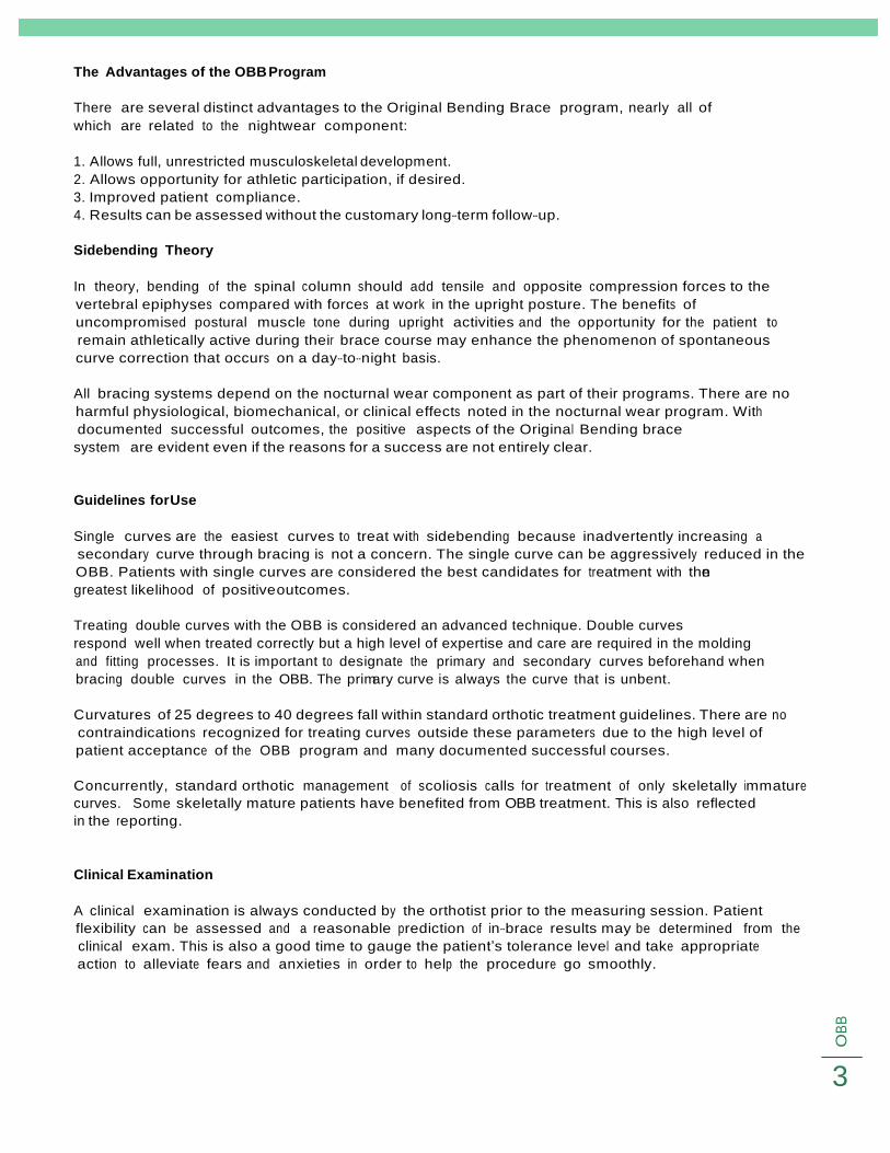
The Advantages of the OBB Program
There are several distinct advantages to the Original Bending Brace program, nearly all of
which are related to the nightwear component:
1. Allows full, unrestricted musculoskeletal development.
2. Allows opportunity for athletic participation, if desired.
3. Improved patient compliance.
4. Results can be assessed without the customary long-term follow-up.
Sidebending Theory
In theory, bending of the spinal column should add tensile and opposite compression forces to the
vertebral epiphyses compared with forces at work in the upright posture. The benefits of
uncompromised postural muscle tone during upright activities and the opportunity for the patient to
remain athletically active during their brace course may enhance the phenomenon of spontaneous
curve correction that occurs on a day-to-night basis.
All bracing systems depend on the nocturnal wear component as part of their programs. There are no
harmful physiological, biomechanical, or clinical effects noted in the nocturnal wear program. With
documented successful outcomes, the positive aspects of the Original Bending brace
system are evident even if the reasons for a success are not entirely clear.
Guidelines for Use
Single curves are the easiest curves to treat with sidebending because inadvertently increasing a
secondary curve through bracing is not a concern. The single curve can be aggressively reduced in the
OBB. Patients with single curves are considered the best candidates for treatment with then
greatest likelihood of positive outcomes.
Treating double curves with the OBB is considered an advanced technique. Double curves
respond well when treated correctly but a high level of expertise and care are required in the molding
and fitting processes. It is important to designate the primary and secondary curves beforehand when
bracing double curves in the OBB. The primary curve is always the curve that is unbent.
Curvatures of 25 degrees to 40 degrees fall within standard orthotic treatment guidelines. There are no
contraindications recognized for treating curves outside these parameters due to the high level of
patient acceptance of the OBB program and many documented successful courses.
Concurrently, standard orthotic management of scoliosis calls for treatment of only skeletally immature
curves. Some skeletally mature patients have benefited from OBB treatment. This is also reflected
in the reporting.
Clinical Examination
A clinical examination is always conducted by the orthotist prior to the measuring session. Patient
flexibility can be assessed and a reasonable prediction of in-brace results may be determined from the
clinical exam. This is also a good time to gauge the patient’s tolerance level and take appropriate
action to alleviate fears and anxieties in order to help the procedure go smoothly.
3

Figure 3a Figure 3b
O B
B
Fig. 2a Fig. 2b
Forward Bending – Have the patient stand
facing away from you with weight
equally distributed on both feet. (Fig. 2a)
With arms extended and palms together,
bend the patient forward to 90 degrees
and stop. (Fig. 2b)
Ask the patient to try and touch the floor
to evaluate hamstring tightness. Observe
and note trunk rotation limitations.
Testing for relative flexibility or stiffness –
Have the patient stand upright and then
bend laterally at the waist. (Fig. 3a)
Note how much range the patient has.
Next, place your hand at the apex of
the curvature and apply a resistive
force. Ask the patient to bend laterally
over your hand. (Fig. 3b)
Note how much range the patient has.
Fig. 3a
Fig. 3b
Radiography
Full-length standing PA X-rays are necessary for the patient evaluation and brace planning. Films should
include the full spine and the iliac crests. Bending films are helpful for evaluation but are not necessary
for brace “blueprinting”. X-rays should be carefully marked “left” or “right”, by the technician. All in-
brace x-rays should be taken in the supine position. If indicated, it should be explained to parents that
modern X-ray techniques limit exposure through advanced equipment, special grids and high-speed
film. Digital X-Rays are preferred.
“Blueprinting”
The “blueprint” is an essential resource for the orthotist during the OBB molding and fabrication
processes. This process determines where the optimal corrective forces should be applied both during
the molding and at brace application.
Center Line—the center line is a vertical drawn on the X-ray indicating where the patient’s spine would
be if it were straight and free from scoliosis.
4

Fig. 6
O B
B
Sacrum visible Locate and mark a spot at the center of S-2.
With a straight edge, measure the distance from the
mark to the edge of the X-ray. (Fig. 4)
Fig. 4
Center Line-At a point several inches above S-2, make
a second mark that same distance from the edge of
the X-ray as the first mark. Draw a vertical line through
the marks. This line is the center line (Fig. 5).
Fig. 5
a b
Vertebral Tilt Angle—The vertebral tilt angle (Fig. 6a) is
formed by the intersection of a line perpendicular to the
c center line (Fig. 6b) and a line drawn across the inferior
endplate of a selected vertebral body. (Fig. 6c) The
vertebral tilt angle is useful in determining the limits of
each scoliotic curve and to properly measure the Cobb
Angle.
Fig. 6
a Pelvic Tilt Angle—The pelvic tilt angle is formed by the
intersection of a line drawn perpendicular to the center
c line (Fig.7a) and a line across the superior edge of the
b iliac crests. (Fig. 7b) The angle formed by the intersection of the two lines is the pelvic tilt angle. (fig. 7c) The line
perpendicular to the center line may be “lowered” until
an angle is formed.
Fig. 7 5

O B
B
Fig. 8
Lumbar/Pelvic Relationship Angle (LPR)— The
LPR is the angle formed by the intersection of the
pelvic tilt line (Fig. 8a) and the
vertebral tilt line of L-3, L-4, or L-5 individually (Fig. 8b).
b
a
a
Curve Limits
1. Locate and draw a center line on the X-ray (Fig. 9a).
2. Draw a vertebral tilt line for each vertebra (Fig. 9b). d c
3. Find the null point by locating a vertebral tilt line, which
is perpendicular to the center line. If no vertebral tilt
lines are perpendicular to the center line, draw a line
perpendicular to the center line, which lies equidistant
between the two most nearly perpendicular lines. This b line will represent the null point (Fig. 9c).
Fig. 9
Cobb
a
4. Begin at the null point and measure the vertebral tilt angles of
each successive superior vertebra. As long as the angle
increases, the vertebral body is included in the curve. The first
vertebra with a lesser tilt angle is not included in the curve. To
locate the most inferior vertebra in the curve, follow the same
procedure and travel in the inferior mode.
5. After locating the superior and inferior vertebral bodies in the
curve, draw a line across the superior endplate of the
superior vertebra and another line across the inferior
endplate of the most inferior vertebra. (Fig.10)
Fig. 10
6

O B
B
Definitions of Terms
Lateral Shift Force: Laterally directed force with 10 degrees to 15 degrees of angulations from the
perpendicular, applied to the apex of the primary curve. Lateral shift force must be sufficient to
move the spine beyond the center line to a point which is equidistant to, and opposite, the original
position and to maintain this position during unbending. This force is the single most important force
in the curve correction process and should never be compromised. (Fig. 11)
Stabilizing Force: Force applied opposite to the lateral shift force at the trochanter or the apex of a
lumbar curve. The intensity of the stabilizing force is dictated by the strength of the lateral shift force.
(Fig. 11)
Unbending Force: The unbending force is the final force applied and is the main curve reducing
force. Pressure is applied at the axillary region opposite the curve’s apex. (Fig. 11) apex of a lumbar
curve, shift force is added at the apex of the thoracic curve, and unbending force is exerted at the
axilla opposite the apex of the thoracic curve. The secondary unbend is made at the trochanteric
region opposite the stabilizing force as an additional corrective measure. (Fig. 11)
Secondary Unbending Force: An advanced technique in which stabilizing force is applied at the
apex of the thoracic curve, and bending force is exerted at the axilla opposite of the apex of the
thoracic curve. The secondary bend is made at the throcanteric region opposite the stabilizing
force as an additional correction measure. (Fig. 18)
Lateral Shift Line
Preferred
Lateral Shift Line
Unbending Force
Lateral Shift Force
Stabilizing Force
Fig. 11
7

O B
B
Maxims for Curve Correction Technique: Effective scoliosis management with the Original Bending
Brace calls for careful, consistent curve reduction technique. Several keys to proper
curve nomenclature and control should become part of the orthotist’s basic knowledge. (Confidence in
and use of these maxims will enable the orthotist to produce an accurate mold with relative ease,
thereby ensuring a satisfactory result).
Classification
King’s Classification of Scoliotic Curvature was originally developed as a pre-operative technique for
selection of spinal fusion segments in scoliotic surgical patients. Now, King’s Classification is an integral
part of the Original Bending Brace system, but for a different purpose.
The use of the original King’s Classification allows practitioners a standard nomenclature for curve
identification. With this common terminology, instruction and feedback are effectively passed between
orthopedist and orthotist. This Classification refers to five categories of scoliotic curvatures, with each
having a distinct appearance and form. The requisites for each category are easy to learn and use,
even if the practitioner has been accustomed to another arrangement.
Curve Patterns
Type I
Lumbar Primary Curve
S-shaped curve in which both thoracic and lumbar curves cross
midline. Lumbar curve is larger than the thoracic curve on
standing film.
Type II
Thoracic Primary Curve S-shaped curve in which thoracic and lumbar curve cross
midline. Thoracic curve is larger than lumbar curve.
Type III
Single Thoracic Curve Thoracic curve in which the lumbar curve does not cross midline
(also called overhang).
Type IV Single Thoracolumbar /
Lumbar Curve
Long thoracic curve in which L5 is centered over sacrum but L4
fits into long thoracic curve.
Type V
Double Thoracic Double thoracic curve with T1 tilted into concavity of upper
curve. Upper curve structural on side-bending.
8
O B
B
OBB
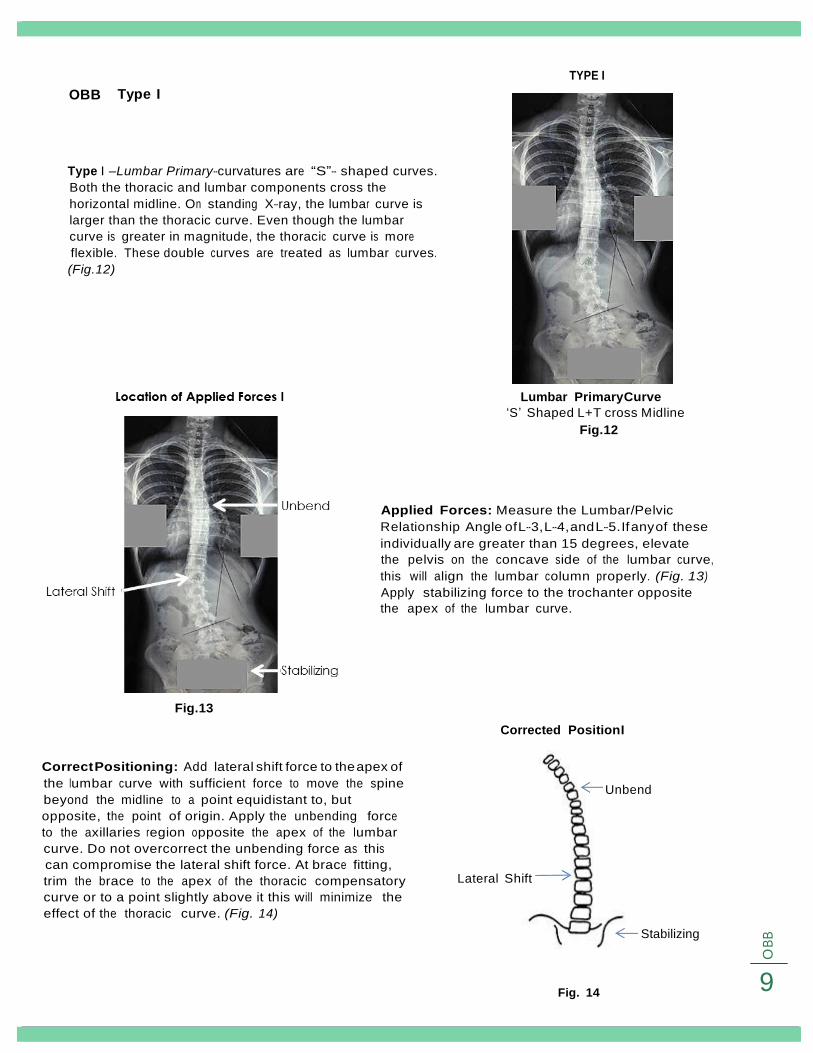
Typ e I
TYPE I
Type I –Lumbar Primary-curvatures are “S”- shaped curves.
Both the thoracic and lumbar components cross the
horizontal midline. On standing X-ray, the lumbar curve is
larger than the thoracic curve. Even though the lumbar
curve is greater in magnitude, the thoracic curve is more
flexible. These double curves are treated as lumbar curves.
(Fig. 12)
Lumbar Primary Curve
‘S’ Shaped L+T cross Midline
Fig. 12
Applied Forces: Measure the Lumbar/Pelvic Relationship Angle of L-3, L-4, and L-5. If any of these
individually are greater than 15 degrees, elevate the pelvis on the concave side of the lumbar curve,
this will align the lumbar column properly. (Fig. 13) Apply stabilizing force to the trochanter opposite
the apex of the lumbar curve.
Fig. 13
Corrected Position I
Correct Positioning: Add lateral shift force to the apex of
the lumbar curve with sufficient force to move the spine
beyond the midline to a point equidistant to, but
opposite, the point of origin. Apply the unbending force
to the axillaries region opposite the apex of the lumbar
curve. Do not overcorrect the unbending force as this
can compromise the lateral shift force. At brace fitting,
trim the brace to the apex of the thoracic compensatory
curve or to a point slightly above it this will minimize the
effect of the thoracic curve. (Fig. 14)
Lateral Shift
Unbend
Stabilizing
Fig. 14
9

O B
B
OBB
Type II
Type II -Thoracic Primary-curvatures are also “S”-shaped.
Again, both the thoracic and lumbar components cross
the horizontal midline. The thoracic segment measures
greater than or equal to the lumbar portion but the
thoracic curve is more flexible. Stabilizing the lumbar
curve and unbending the thoracic segment best treat
these curves. (Fig. 15)
Fig. 16
Fig. 15
Applied Forces: Measure the vertebral tilt angle of L-
3, L-4, and L-5. If the VTA of any of these three,
individually, is greater than 10 degrees, then apply the
stabilizing force at the apex of the Lumbar curve. If
the VTA of any of these vertebra measures less than 10
degrees, apply the stabilizing force at the trochanter.r.
Measure the lumbar pelvic relationship (LPR) angle of
L-3, L-4, and L-5. If any of these angles individually
measures greater than 15 degrees, elevate the pelvis
on the concave side of the Lumbar Curve.
Apply a lateral shift force at the apex of the Thoracic
curve and shift beyond the midline as much as
possible (applying substantial pressure).
Corrected Position: Apply an unbending force in
the axilla region but be careful not to compromise
or overpower the lateral shift force.
If the LPR angle of L-3, L-4, or L-5 is greater than 10
degrees, then apply a secondary unbending force
at the trochanter opposite the stabilizing force. This
secondary unbending force is the last force
applied and is a laterally directed force. (Fig. 17)
Corrected Position II
Unbend
VT Angle >10
Stabilizing
Force
VT Angle <10
Fig. 17
Lateral
10

O B
B
Secondary Unbending Force: (Advanced technique)
Applied Force: in which a stabilizing force is applied at the apex of the thoracic curve, and bending
force is exerted at the axilla opposite of the apex of the thoracic curve. The secondary unbend is
made at the trocanteric region opposite the stabilizing force as an additional correction measure. (Fig. 18)
Fig. 18
The in-brace thoracic curve
should be corrected to 100%
and the lumbar curve to 50%
in-brace x-ray.
If the thoracic and lumbar curves are at 20 degrees or less and
within 5 degrees of each other,
treating a Type I-Lumbar Primary as a Type II-Thoracic Primary is
appropriate.
If the thoracic is 27 degrees or greater trim the unbend to the
thoracic apex;; under 27 degrees, leave the unbend high for
maximum correction of the lumbar. If progression occurs, then trim
to the thoracic apex.
A lumbar curve of 35 degrees or greater should always be treated as Type I curve to control the lumbar
curve. Always consider Risser age, curve degrees, menses, and family history in deciding treatment.
11

O B
B
OBB
Type III
Type III- Single Thoracic- curvatures are essentially
thoracic curves. The lumbar segment does not cross
the midline in Type III. This pattern presents the so-
called “Overhang” appearance. Type III curves
generally present little difficulty in treatment. (Fig. 19)
Fig. 19
Fig. 19
Applied Force: The correction method for Type III is
less difficult than Type II because by definition the
Lumbar vertebra will not cross the midline or tilt in
the opposite direction of the curve or it will be a
Type II curve.
However, we still measure the LPR angle and the VT
angle to confirm our diagnosis. In some instances
the LPR angle may be greater than 15 degrees if
the pelvic tilt angle is unusually large.
Fig. 20
Corrected Position III
Corrected Position: The location of forces applied is to
apply the stabilizing force at the trochanter and then
the lateral shift force at the apex of the thoracic curve,
shifting beyond the midline as far as possible.
Last apply the unbending force in the axilla region
opposite the L.S. force being careful not to
compromise or overpower the L.S. force. (Fig. 21)
Unbend
Lateral Shift
Stabilizing Fig. 21
12

O B
B
OBB Type IV
Type IV-Single Thoracolumbar / Lumbar- scoliosis is characterized
by long thoracic (thoracic /thoracolumbar) curves in which the
body of L-5 is centered over the sacrum but the body of L-4 is
tilted into the curved segment.
These curves are best treated as thoracolumbar curves, but
emphasis should be placed on shifting the spine to the midline
prior to unbending. (Fig. 22)
Applied Force: In a Type IV curve there is no
need to measure or consider the LPR angle
or the VT angle because, by definition of
curve types, they will not be a factor. This
type curve is a single curve with L-4 tilted into
the curve. (Fig. 23)
Fig. 22
Fig. 23
Correct Position IV
Corrected Position: The location of forces for a Type IV
curve is to apply the stabilizing force at the trochanter
opposite the apex of the thoracolumbar curve, apply the lateral shift force at the apex of the curve and shift laterally beyond the midline as great a distance as possible.
Apply the unbending force in the axilla and unbend,
being careful not to compromise or overpower the
lateral shift force. (Fig. 24)
Unbend
Lateral Shift
Stabilize
13
Fig. 24

O B
B
OBB Type V
Type V- Double Thoracic- curvatures are double
thoracic curves with the body of T-1tilted into the
concavity of the upper curve. The thoracic segment
appears to be structural on X-ray. Type V curvatures are
treated as thoracic curves. (Fig. 25)
Fig. 25
Applied Force: Apply a stabilizing force at the
trochanter opposite the apex of the thoracic
curve.
Then add lateral shift force to the apex of the
thoracic curve, using sufficient force to move the
spine beyond the midline to a point equidistant to,
but opposite, the original starting position.
Finally, add unbending force to the axilla opposite
the apex of the thoracic curve. (Fig. 26)
Fig. 26
Correct Position
Unbend
Corrected Position: The curve correction
technique is identical to that used in Type
IV curvatures. (Fig. 27)
Lateral Shift
Stabilize
Fig. 27
14

O B
B
Understanding Balanced Forces:
When applying stabilizing, shifting and unbending forces to the spinal column, it is paramount that the
forces be balanced so to prevent gross decompensation, with little or no curve correction.
Properly distributed forces are essential to successful curve reduction. Unbending forces should not be
applied until the lumbar column has reached the midline. (Fig. 28a and 28b)
Incorrect Correct
Fabrication
Fig. 28a Fig. 28b
Brace Fabrication and Quality Control
Because X-ray interpretation and cast modification are critical to the brace manufacturing process, a
specialized and highly trained source is required for fabrication. The exclusive manufacturing and
quality control responsibility for the Original Bending Brace has been licensed to Original Bending Brace LLC
who coordinates data accumulation / transfer and management in cooperation with
Bending Brace Foundation.
OBB/CBB Manufacturing Pre-requisites:
• Blueprinted x-ray (determining location of applied forces)
• Complete OBB work order
Digital x-ray (Preferred) can be emailed directly to:
Jackie@ cbb.org
Subject: OBB
Brace Fitting and Check-Out
When the new OBB is received, careful attention to trim and fit requirements are the responsibility
of the attending orthotists.
1. Place the patient in standing. Straps remain unfastened.
2. Have the lay down supine.
3. Locate the waist indentation on the brace and position it between the patient’s ribs and iliac crests.
4. Fasten the Velcro straps and evaluate the axillary trim. Trim for maximum axillary pressure.
5. The patient should be able to lower the arm completely without discomfort. NOTE: The plastic flare
above the lateral shift force is expected to be higher than the apex.
15
O B
B
6. On the concave side of the brace, the proximal edge of the brace should lie at the apex of the
curve. If the trim is too high, the patient will be allowed to bend over the apex of the curvature and
the amount of curve correction will be compromised.
7. Trim the antero-proximal edge of the brace for breast relief.
8. The antero-distal trim line should be at or slightly proximal to the gluteal fold. If the trim is too high,
the patient will experience discomfort.
9. The postero-distal trim line should be at or slightly proximal to the gluteal fold. If the trim is too high,
the patient will experience discomfort.
10. The postero-proximal trim line should describe a smooth diagonal line transitioning form the high,
convex side of the brace to the lower concave side.
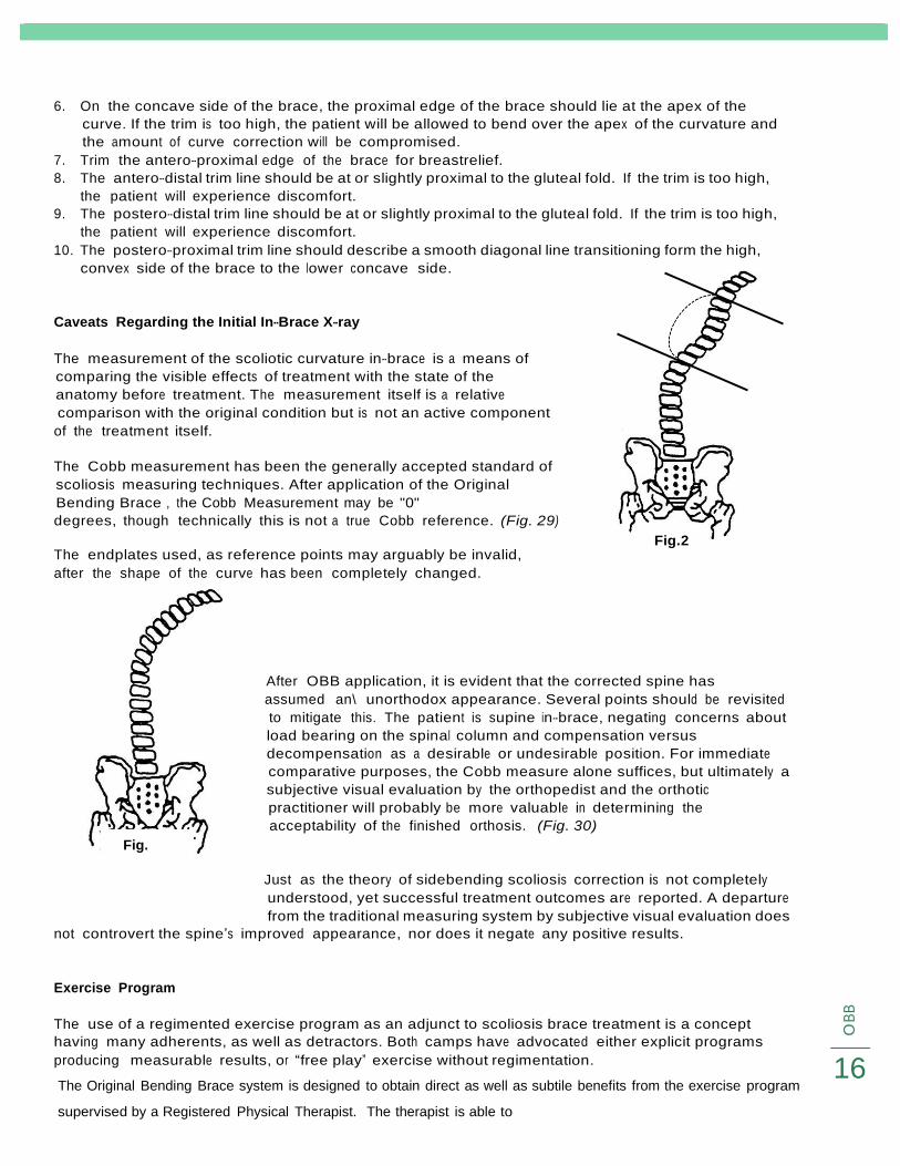
Caveats Regarding the Initial In-Brace X-ray
The measurement of the scoliotic curvature in-brace is a means of
comparing the visible effects of treatment with the state of the
anatomy before treatment. The measurement itself is a relative
comparison with the original condition but is not an active component
of the treatment itself.
The Cobb measurement has been the generally accepted standard of
scoliosis measuring techniques. After application of the Original
Bending Brace , the Cobb Measurement may be "0"
degrees, though technically this is not a true Cobb reference. (Fig. 29)
The endplates used, as reference points may arguably be invalid,
after the shape of the curve has been completely changed.
Fig. 2
Fig.
After OBB application, it is evident that the corrected spine has
assumed an\ unorthodox appearance. Several points should be revisited
to mitigate this. The patient is supine in-brace, negating concerns about
load bearing on the spinal column and compensation versus
decompensation as a desirable or undesirable position. For immediate
comparative purposes, the Cobb measure alone suffices, but ultimately a
subjective visual evaluation by the orthopedist and the orthotic
practitioner will probably be more valuable in determining the
acceptability of the finished orthosis. (Fig. 30)
Just as the theory of sidebending scoliosis correction is not completely
understood, yet successful treatment outcomes are reported. A departure
from the traditional measuring system by subjective visual evaluation does
not controvert the spine’s improved appearance, nor does it negate any positive results.
Exercise Program
The use of a regimented exercise program as an adjunct to scoliosis brace treatment is a concept
having many adherents, as well as detractors. Both camps have advocated either explicit programs
producing measurable results, or “free play” exercise without regimentation. 16 The Original Bending Brace system is designed to obtain direct as well as subtile benefits from the exercise program
supervised by a Registered Physical Therapist. The therapist is able to

O B
B
The Original Bending Brace system is designed to obtain direct as well as subtile benefits from the exercise
program supervised by a Registered Physical Therapist. The therapist is able to
recognize the strengths and deficits of each individual patient make recommendations, set up
programs, and document results. The therapist may also serve as a patient’s and family’s motivator by
altering the program at intervals to freshen the routine.
The Registered Physical Therapist is able to conduct an individual needs assessment, measure the
patient’s strength and flexibility, and evaluate such aspects as body control, dexterity and
proprioception. Special programs may be incorporated, including aerobic and recreational dance or
other exercise routines, which are often in conjunction with organized sports.
The goals of supervised exercise programs are to:
1. Maintain or increase muscle strength and tone
2. Maintain or increase flexibility
3. Promote correct postural alignment
4. Increase awareness of body position
Components of the program may include:
1. Pelvic tilt-supine or upright
2. Abdominal, gluteal and shoulder girdle strengthening
3. Hamstring, hip flexor and pectoral strengthening
4. Diaphragmatic or other deep breathing exercises
17
OB
B
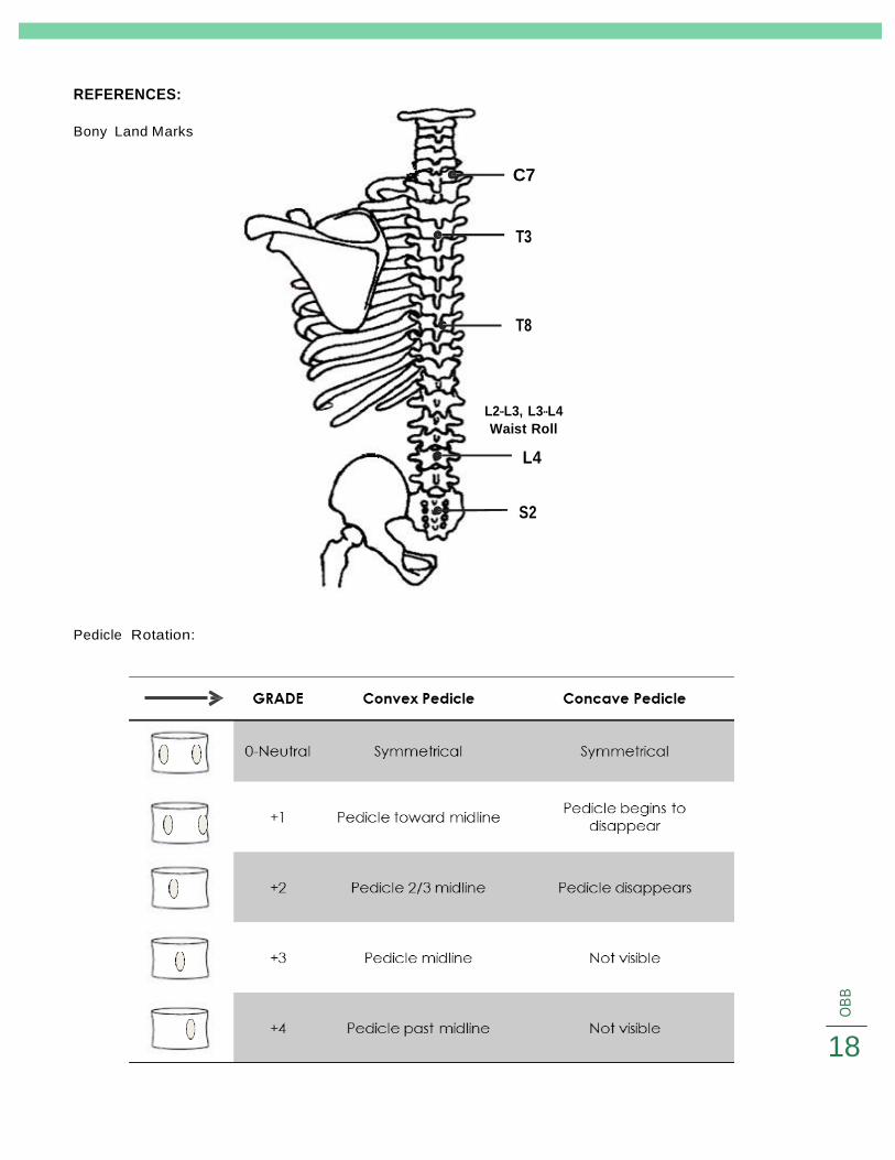
REFERENCES:
Bony Land Marks
Pedicle Rotation:
C7
T3
T8
L2-L3, L3-L4
Waist Roll
L4
S2
18

5
O
BB
Risser Sign:
Open Fused
ADDITIONAL INFORMATION:
Weinstein, et al. New England Med September 2013
• Bracing in Adolescent Idiopathic Scoliosis Treatment (BRAIST)
• Bracing significantly decreased the progression of high-risk curves to the threshold for surgery
• Significant association between the average hours of daily brace wear and the likelihood of a
successful outcome
• The benefit increased with longer hours of brace wear
19

O B
B
ILLUSTRATIONS Figure Page
Kalibis Splint Fig. 1 2
Forward Bend
Lateral Bend
Center Line
Fig. 2a, 2b
Fig. 3a, 3B
Fig. 4, 5
4
4
5
Vertical Tilt Line
Pelvic Tilt Angle
Lumbar Pelvic Relationship (LPR)
Curve Limits Cobb
Fig. 6
Fig. 7
Fig. 8
Fig. 9
5
5
6
6
Cobb Angle
Definition of Terms-imgage
King Classification-curve patterns
Type I
Fig. 10
Fig. 11
image
Fig. 12, 13, 14
6
7
8
9
Type II
Secondary unbend
Type III
Type IV
Fig. 15, 16, 17
Fig. 18
Fig. 19, 20, 21
Fig. 22, 23, 24
10
11
12
13
Type V
Unbalanced Forces
X-ray caveats
Fig. 25, 26, 27
Fig. 29, 30
14
15
17
REFERENCES
Bony Landmarks 18
Pedicle Rotation 19
Risser Sign 19
20