the pacific northwest smart grid demo
TRANSCRIPT

The Pacific Northwest Smart Grid Demo Transactive Control Implementation
Ron Ambrosio Global Research Executive, Energy & Utilities Industry Senior Technical Staff Member IBM TJ Watson Research Center, Yorktown Heights, NY
Chairman Emeritus & Member, U.S. Dept. of Energy GridWise Architecture Council Chairman, U.S. National Inst. of Standards and Technology SGIP Architecture Committee Convenor, ISO/IEC JTC 1 Special Working Group on Smart Grid

2
Let’s start at 100,000 feet

Smart Grid Conceptual Model

= information path
PNW Transactive Control Incentive Flow

The GWAC Stack and the Model Analyze interoperability at key inter-system points in the use case paths through the Conceptual Model …
… using the GWAC Stack top-down to define lowest layer that must be addressed
Organizational (Pragmatics)
8: Economic/Regulatory Policy
7: Business Objectives
6: Business Procedures
Informational (Semantics)
5: Business Context
4: Semantic Understanding
Technical (Syntax)
3: Syntactic Interoperability
2: Network Interoperability
1: Basic Connectivity

6
Transactive Control

7
Transactive Control of Energy Delivery • What is it?
– A flexible method for combing multiple objectives and constraints (both economic and operational) using uniform incentive and feedback signals throughout an electricity grid.
• Incentive and feedback signals – An incentive signal is used by electricity assets to make decisions
about their future consumption pattern – it is a forward signal with information for the next few days.
– A feedback signal represents that consumption pattern over the same few days, in response to the incentive.
• Creation of the incentive signal – Regional and local objectives are “monetized” and incorporated into
the signal as it flows through each transactive control node in the system
– Objectives could include: • Congestion Relief • Encouraging the use wind power • Reducing peak load • Reducing phase imbalance on a transformer • Avoiding overloading a distribution line
Upstream (toward generation)
Downstream (toward demand)
Incentive Signal
Feedback Signal
Modified Feedback
Signal
Modified Incentive
Signal
Transactive Control
Algorithm
z
$
P
Signals forecast several days

Some Definitions
• Transactive Control – A single, integrated, smart grid incentive signaling approach utilizing
an economic signal as the primary basis for communicating the desire to change the operational state of responsive assets.
• Transactive Incentive Signal (TIS) – A representation of the actual delivered cost of electric energy at a
specific system location (e.g., at a transactive node). Includes both the current value and a forecast of future values.
• Transactive Feedback Signal (TFS) – A representation of the net electric load at a specific system location
(e.g., at a transactive node). Includes both the current value and a forecast of future values.
8

Propagation of the incentive and feedback signals Incentive signals and feedback signals propagate through an information network (the transactive control system) that overlays the electrical network
G
G
G
Information Network
PhysicalNetwork

Transactive Node Structure for Demo
TZ-13: MT
BA- NorthWestern Energy
UT-Northwestern Energy
ST-Helena ST-Philipsburg
TZ-12: Central Oregon
BA-BPA
UT-Flathead Electric
ST-Libby ST-Haskil
BA-Avista
UT- Avista
ST-Pulman
TZ-14: South Idaho
BA-Pacificorp
UT-Lower Valley
ST- Teton-Palisades
Power Interconnect
UT-Idaho Falls Power
ST-DA &Energy
Management
ST- Loop Microgrid
TZ-8: OR Cascades
TZ-6: Northcentral Washington
BA- BPA
UT-Ellensburg
ST-Ellensburg Renewable Park
TZ-10: N. Idaho
Canada@ Boundary
TIS SignalTFS Signal
TZ-11: NE Oregon
BA- BPA
UT-Milton-Freewater
ST-Milton-Freewater
TZ-7: Hanford
BA- BPA
UT-Benton PUD
ST-Reata
TZ-9: Southcentral OR
TZ-5: Western OR
BA-Portland General
UT-PGE
ST-Salem
TZ-4: Allston
TZ-3: Paul
EasternMontana
TZ-2: West Washington
BA-BPA
UT-Peninsula Light
ST- Fox Island
UT-Seattle City Light
ST- UW Campus
BA-SCL
TZ-1: NW Washington
FG-N.Cascades North
FG-Monroe-Echo Lake
FG-R
aver Paul
FG-PaulAllston
FG-AllstonKeeler
FG-W
. North of H
anford
FG-W of Hatwai FG-MT to NW
FG-Lolo
FG- LaG
rande
FG-Enterprise
FG- W
. of McN
ary
FG-W. of Slatt
FG-W
. of John Day
FG-E. of John Day
FG-S. Cascades
FG-N.CascadesSouth
FG-E
. North of H
anford
Canada@ Custer
Wes
t CO
I
FG- P
DC
I
FG-East COI
Wyoming
Nevada
TZ – Transmission ZoneBA – Balancing AuthorityUT – Utility (of Subproject)ST – Site (of Subproject)FG – Flowgate
FG- Harney and Midpoint
Transactive Control Node
Northern Montana
Regional and Subproject Transactive Control Nodes & Network Topology

11
ISO/IEC 18012 interoperability framework IBM Internet-scale Control Systems (iCS)
Now we’re at 10,000 feet
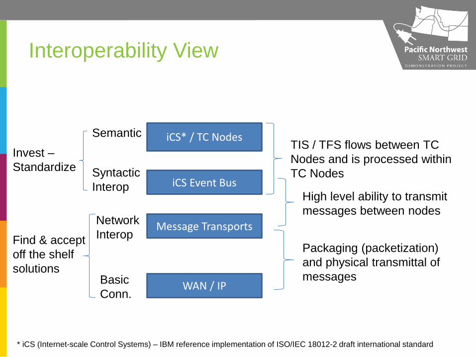
Interoperability View
Semantic
Syntactic Interop
Network Interop
Basic Conn.
iCS* / TC Nodes
iCS Event Bus
Message Transports
WAN / IP
TIS / TFS flows between TC Nodes and is processed within TC Nodes
High level ability to transmit messages between nodes
Packaging (packetization) and physical transmittal of messages
Invest – Standardize
Find & accept off the shelf solutions
* iCS (Internet-scale Control Systems) – IBM reference implementation of ISO/IEC 18012-2 draft international standard
13 © 2009 IBM Corporation
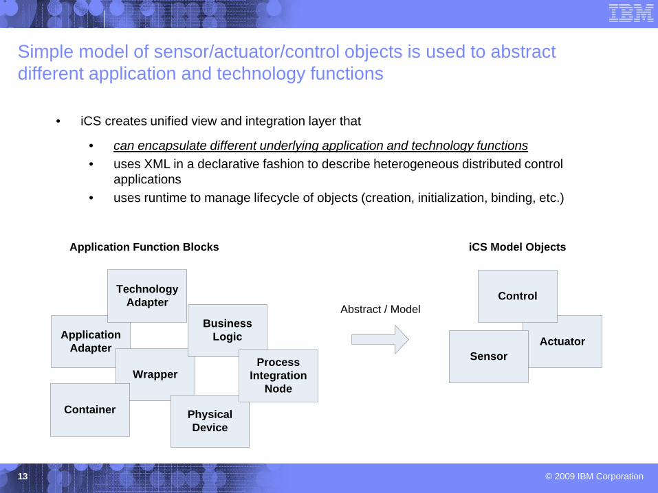
Simple model of sensor/actuator/control objects is used to abstract different application and technology functions
ApplicationAdapter
TechnologyAdapter
Wrapper
PhysicalDevice
Business Logic
ProcessIntegration
Node
ActuatorSensor
Control
iCS Model Objects
Abstract / Model
Application Function Blocks
Container
• iCS creates unified view and integration layer that
• can encapsulate different underlying application and technology functions • uses XML in a declarative fashion to describe heterogeneous distributed control
applications • uses runtime to manage lifecycle of objects (creation, initialization, binding, etc.)

14 © 2009 IBM Corporation
Component Model: Control Element (iCS Building Block)
14
Controller
Sensor
Actuator
Controller
<<iCS Control-Processing Element>>
Controller Model
Input E/M Queue
Model Processor
Application Logic(“Model Algorithm”)
Inputs Description
Table
i1
i2
i3
i4
Outputs Description
Table
Inpu
t Dat
a Po
ints o1
o2
Output E/M Queue
TimerScheduler Thread Pool
EventCorrelation
ConfigurationProperties,Parameters
ConfigurationProperties,Parameters
Out
put D
ata
Poin
ts
FSM
I/O D
ata/Event M
essage Interface
Service-Invocation Interface
I/O D
ata/Event M
essage Interface
Service-Invocation Interface
Application Logic: Composition of Control Elements
Construct of Control Element: Simple application abstraction spans
from business processes to physical devices
Runtime implementation scales from embedded to enterprise server environment
• Designed and implemented with Java Micro Edition (ME) as minimum target
Establishes a hybrid application programming model to integrate both enterprise (business) and embedded control (operational) domains:
• Asynchronous event programming • Service Oriented Architecture
transactional programming

15 © 2009 IBM Corporation
• Separation of Object Implementation from Composition and Integration • Minimizes interference between the two communities of programmers:
• Component Developers • System Integrators
• Allows event flow of application to be modified with no impact on Object Implementation
• Separation of application topology from device topology • Minimizes impact of device evolution and reconfiguration • Simplifies reconfiguration of application for tuning, etc. • Increases level of reusability of Objects
Important to establish certain separations in the programming abstraction
iCS XML Information Model
Model Object
Application Data/Event Flow Path
Model Developer
Model & ApplicationIntegrator
iCS Runtime
Define & Code
Declare Construct &Validate
Construct, Schema Validation,& Code Assembly

16
Transactive Node Object Model (TNOM)
Now we’re at 1,000 feet

Stack Structure
ICS
OS
Proxy
ICSTNOMB ProxyTNOMB
TNOMB
TNOMT
TNMA
Implementation Specific
Implementation Independent
Portable Program Interface (IContext)
Common Services Base
Windows or Linux
100% Pure Java (1.6)
Platform Interface
1/10/2

Stack Structure
ICS
OS (Windows/Linux)
Proxy
ICSTNOMB ProxyTNOMB
TNOMB
TNOMT
TNMA
TNSM TNDC TNTS
SM Connector
TN Connector
Neighbor Interface
Common Services
Single Java 1.6 Runtime
SM DC
SM Impl.
1/10/2

Stack Structure
ics
OS (Windows/Linux)
proxy
ics proxy
common
common
common
common common common
common common
common
common
Single Java 1.6 Runtime
common common common
ics
1/10/2

20
Transactive Node Model Algorithm (TNMA), Transactive Toolkit Functions
and local responsive assets
Finally down in the weeds
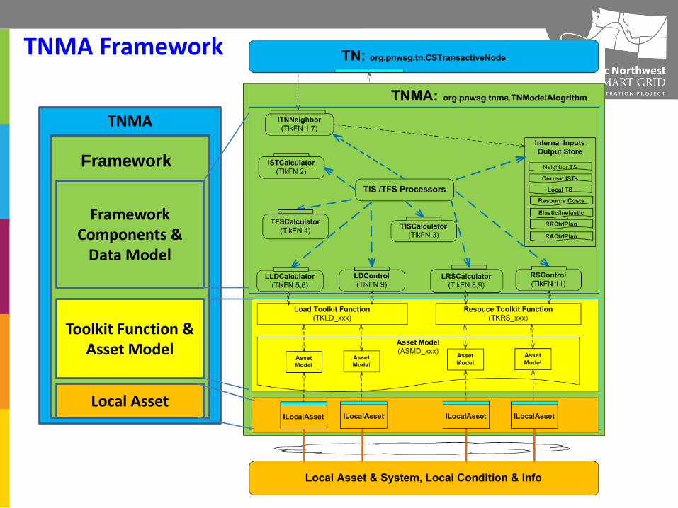
TNMA
TNMA Framework
21
Toolkit Function & Asset Model
Local Asset
Framework
Framework Components &
Data Model

Foundation of TIS/TFS Computing of Transactive Node: Toolkit Function, Asset Model and Local Asset
TNMA Framework
Local Asset
Toolkit Function Alogrithm
Local Condition Information
Local AssetSystems
conn conn
Asset Model
Command, control
Statesupdate
conn conn

Toolkit Function & Asset Model Toolkit Function
– A mathematic algorithm or control model that takes set of input data to compute output data needed for TIS/TFS calculation for a specific type of local asset or asset-system.
– The input data set of a Toolkit function includes: • Current states and condition of local asset • Local information related to local asset • Current states of Transactive Node
– The output data set of a Toolkit function is used by TNMA Framework for TIS/TFS calculation.
– There are two categories of Toolkit Function: Resource and Load
– Created and managed by Framework; uniquely identified by Toolkit Function ID (type and version)
– Algorithm Code is represented and captured JAVA object class in Framework

Asset Model
Asset Model – A software object represents
current states, local condition or static characteristics/configuration of a local asset of an asset-system
– A data abstraction model viewed by a Toolkit Function of local asset or asset-system
– It is the input data of a specific Toolkit Function object
– Each Asset Model is typed or associated with a JAVA object class in Framework
– Each instance of an Asset Model object is referenced and used by two objects in Framework: • A Toolkit Function object • A Local Asset object
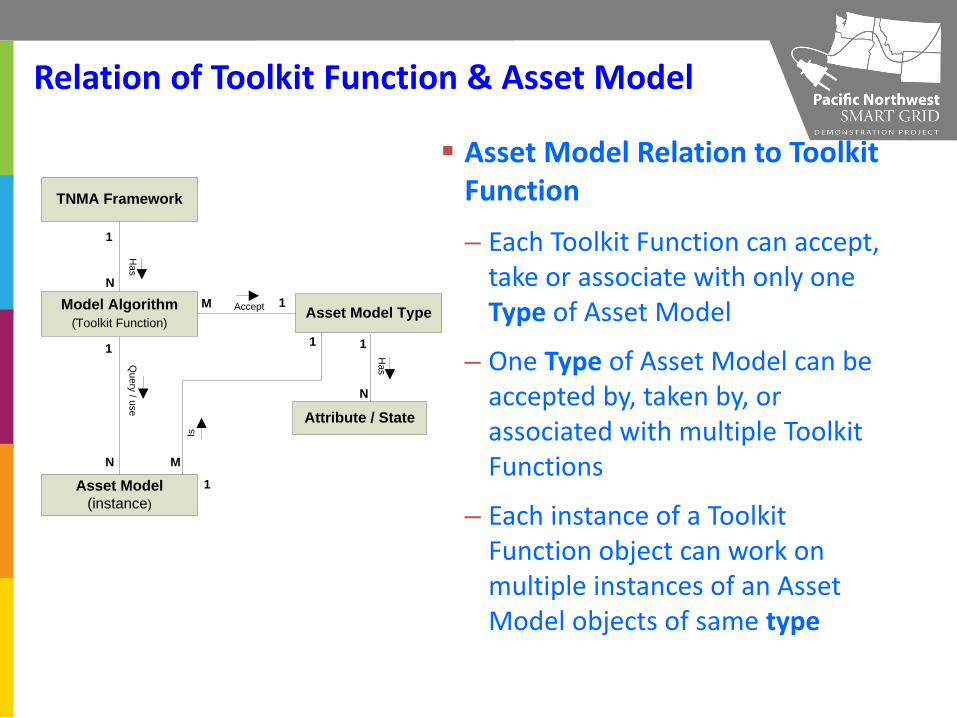
Relation of Toolkit Function & Asset Model
Model Algorithm(Toolkit Function)
Asset Model (instance)
Attribute / State
TNMA Framework
N
Has
Query / use
1
N
1 Has
1Asset Model Type
1
M
1
M
1
N
Is
Accept
Asset Model Relation to Toolkit Function
– Each Toolkit Function can accept, take or associate with only one Type of Asset Model
– One Type of Asset Model can be accepted by, taken by, or associated with multiple Toolkit Functions
– Each instance of a Toolkit Function object can work on multiple instances of an Asset Model objects of same type
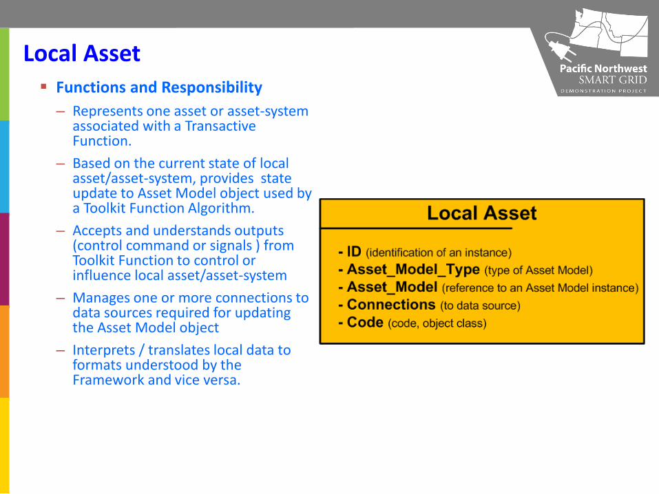
Local Asset Functions and Responsibility
– Represents one asset or asset-system associated with a Transactive Function.
– Based on the current state of local asset/asset-system, provides state update to Asset Model object used by a Toolkit Function Algorithm.
– Accepts and understands outputs (control command or signals ) from Toolkit Function to control or influence local asset/asset-system
– Manages one or more connections to data sources required for updating the Asset Model object
– Interprets / translates local data to formats understood by the Framework and vice versa.

Local Asset
Relation to Framework: – Local Asset is developed and owned by a
Transactive Node owner/manager
– Loaded and managed by the Framework
– Local Asset and Toolkit Function forms data supply-and-consume relationship through the Asset Model object
– Each Asset Model update consists of the following actions • Update the model object • Notify framework (through callback) • Accept Transactive Control command
from Toolkit Function and send to local asset
Framework
Local Asset
Toolkit Function Alogrithm
Local Condition Information
Local AssetSystems
conn conn
Asset Model
get()/set()
get()/set()
Command, control
Statesupdate
conn conn

Local Asset Relation to Asset Model and Toolkit Function
Model Algorithm(Toolkit Function)
Asset Model (instance)
Attribute / State
Local Asset (instance)
TNMA Framework
N
Update Model Data
Has
Query / use
Inputs Outputs
1
N
Has or manage
1
1
MN
N
1
1
Has
1Asset Model Type
1
M
1
M
1
N
Is
1
1
Sup
port
Bel
ongs
/ A
ssoc
iate
d w
ithAcceptH
as

IBM Research
© 2010 IBM Corporation
Ron Ambrosio Global Research Executive Energy & Utilities Industry Ron Ambrosio/Watson/IBM@IBMUS [email protected] +1 914-945-3121 IBM T.J. Watson Research Center P.O. Box 218 1101 Kitchawan Rd. / Route 134 Yorktown Heights, NY 10598
Contact
IBM Research
© 2010 IBM Corporation 30