the ph handbook - xyleminfo.xyleminc.com/rs/198-dll-407/images/ysi_the_ph_… · ·...
TRANSCRIPT
The pH Handbooka practical guide to pH measurement
YS
I LA B O R A T O R Y pH
RE
PEATA B LE. T RUSTE
D.

Connect with YSI on:
YouTubeyoutube.com/ysiinc
Tumblrmyysi.tumblr.com
Pinterestpinterest.com/myYSI
Slideshareslideshare.net/ysiinc
Subscribe to the YSI blogysi.com/ysi-blog
Facebook facebook.com/myYSI
Twittertwitter.com/ysiinc
Scoop.itscoop.it/ysi-inc
LinkedInlinkedin.com/company/ysi
YS
I LA B O R A T O R Y pH
RE
PEATA B LE. T RUSTE
D.

C o n t e n t s
Introduction .........................................................................................1
Chapter 1: Basic Concepts of pH Measurement ............................2
1.1 Dissociation of water and formation of the hydronium ion ........................................................................2
1.2 Definition of acid and base ...................................................3
1.3 Ion activity and ion concentration ........................................3
1.4 pH and the pH scale ...............................................................4
1.5 pH measurement methods ....................................................6
1.6 Potentiometry .........................................................................8
Chapter 2: Glass pH Electrode Structure and Design ................. 14
2.1 Electrode body .....................................................................15
2.2 Glass membrane ..................................................................15
2.3 Reference system .................................................................16
2.4 Reference electrolyte ..........................................................18
2.5 Reference junction ...............................................................20
2.6 Double and triple junction electrodes ...............................22
Chapter 3: Calibration and Measurement Procedures ............... 23
3.1 Buffers and importance of temperature ............................23
3.2 Verifying electrode response and slope ............................25
3.3 Calibration frequency ..........................................................26
3.4 Number of calibration points ..............................................26
3.5 Placing a pH electrode in solution ......................................27
3.6 Calibration tips and troubleshooting .................................30
3.7 Calibration data ....................................................................32

Chapter 4: Electrode Maintenance and Storage ......................... 34
4.1 Electrode cleaning ...............................................................34
4.2 Electrode storage .................................................................36
4.3 Conditioning dried pH electrodes .....................................38
Chapter 5: Selecting the Best Electrode ...................................... 39
5.1 YSI lab electrode families ....................................................39
5.2 Electrode Selection and Application Guides ....................42
Final words .........................................................................................48

1
Introduction
With over 65 years of experience in developing, manufacturing, and supporting our customers with best-in-class instrumentation for the lab and field, YSI has an established reputation as experts in the measurement of a multitude of parameters.
pH is an incredibly important parameter that is measured in nearly every water quality application. It plays a role in the taste (acid = fresh, neutral = bland, and alkaline = inedible) and the preservation of food. In environmental sampling and monitoring, high or low pH values can be indicative of pollution. In wastewater treatment, pH is regulated as part of discharge permitting and many treatment processes are pH dependent. In biotechnology, pH must be closely monitored during the production of immunoassay solutions. These are just a few of the many applications in which the pH measurement is a valuable tool.
This brief pH handbook is designed to introduce the most essential aspects of pH measurement. It covers basic concepts of pH measurement as well as practical topics such as tips for calibration, measurement, storage, and cleaning. A discussion of electrode design is included and guides for selecting the most appropriate lab pH electrode appear at the end. Although this handbook is primarily focused on the measurement of pH in the laboratory, tips are also provided for field pH measurement throughout the handbook.
This handbook is not designed to serve as a replacement operating manual for your pH instrument or electrode. Please consult the user manual for specific instructions and recommendations.
YSI offers seminars on the topic of pH measurement which may apply to continuing education units depending on the certifying agency. If you would like to schedule a seminar for your group or organization, please contact YSI at [email protected], 1-800-897-4151 or +1 937-767-7241.
YS
I LA B O R A T O R Y pH
RE
PEATA B LE. T RUSTE
D.

2
+
Water molecule
Hydroxide ion
Hydrogen ion(proton)
Water moleculeHydronium ion
Chapter 1: Basic Concepts of pH Measurement
1.1 Dissociation of water and formation of the hydronium ion
Whether an aqueous solution reacts as an acid or a base depends on its hydrogen ion (H+) content. Even chemically pure, neutral water contains hydrogen ions due to the autodissociation of water. In this process, water molecules are broken up into simpler constituents (i.e. ions). The dissociation of water is represented in equation [1]:
1 H2O H+ + OH-
In this reaction, H2O is deprotonated (i.e. loses a proton). This results in the formation of a positively charged hydrogen ion (H+) and a negatively charged hydroxide ion (OH-). In chemical equations, the hydrogen ion is commonly used to represent a proton.
The hydrogen ion does not remain a free proton for long, as it is quickly hydrated by a surrounding un-ionized water molecule. The formation of the resulting ion, the hydronium ion, is represented in equation [2]:
2 H2O + H+ H3O+
Figure 1.1 combines equations [1] and [2] to show the sequence of hydronium ion formation.
Figure 1.1: Dissociation of water and the formation of the hydronium ion

3
In 1 L of pure, neutral water at 760 mmHg (standard atmospheric pressure at sea level) and 25 oC, there are 10-7 mol H+ ions and 10-7 mol OH- ions.
1.2 Definition of acid and base
Acids are substances which release hydrogen ions (i.e. protons), so a solution is considered acidic if it contains more hydrogen ions than neutral water.
Bases are substances which accept hydrogen ions. When bases are dissolved in water, they bind to some of the hydrogen ions formed from the dissociation of water. Basic solutions contain fewer hydrogen ions than neutral water.
Aqueous solutions are considered acidic if they contain >10-7 mol L-1 of hydrogen ions and basic if they contain <10-7 mol L-1 of hydrogen ions at 25 °C.
Acids and bases neutralize each other, resulting in the formation of water and salt. An example would be the reaction of sodium hydroxide (NaOH) and hydrochloric acid (HCl) in equation [3]:
3 NaOH + HCl NaCl + H2O
A reaction between an acid and base involves a transfer of protons. In the above acid-base reaction, a proton is donated from HCl (acid) to NaOH (base) to form sodium chloride (NaCl) and water.
1.3 Ion activity and ion concentration
Ions carry either a positive (e.g. H+) or negative (e.g. OH-) charge. As charge carriers, all dissolved ions exert electrical forces on their surroundings. While a solution might be electrically neutral on a macroscopic scale, the effects of ions can be drastic at the microscopic scale.
Solutions may behave as if some of the ions are not present. This apparent loss of ions is caused by the interaction of ions in solution, ultimately resulting in significant deviations from ideal behavior. In order to take this interaction into account, the ion activity, also known as the effective ion
4
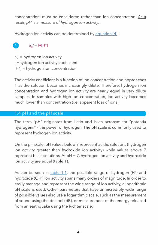
concentration, must be considered rather than ion concentration. As a result, pH is a measure of hydrogen ion activity.
Hydrogen ion activity can be determined by equation [4]:
4 aH+= f•[H+]
aH+= hydrogen ion activity
f =hydrogen ion activity coefficient[H+] = hydrogen ion concentration
The activity coefficient is a function of ion concentration and approaches 1 as the solution becomes increasingly dilute. Therefore, hydrogen ion concentration and hydrogen ion activity are nearly equal in very dilute samples. In samples with high ion concentration, ion activity becomes much lower than concentration (i.e. apparent loss of ions).
1.4 pH and the pH scale
The term “pH” originates from Latin and is an acronym for “potentia hydrogenii” - the power of hydrogen. The pH scale is commonly used to represent hydrogen ion activity.
On the pH scale, pH values below 7 represent acidic solutions (hydrogen ion activity greater than hydroxide ion activity) while values above 7 represent basic solutions. At pH = 7, hydrogen ion activity and hydroxide ion activity are equal (table 1).
As can be seen in table 1.1, the possible range of hydrogen (H+) and hydroxide (OH-) ion activity spans many orders of magnitude. In order to easily manage and represent the wide range of ion activity, a logarithmic pH scale is used. Other parameters that have an incredibly wide range of possible values also use a logarithmic scale, such as the measurement of sound using the decibel (dB), or measurement of the energy released from an earthquake using the Richter scale.

5
Table 1.1: Hydrogen ion and hydroxide ion activities on the pH scale
pH H+ Activity OH- Activity0 1.E+00 1 0.000000000000011 1.E-01 0.1 0.00000000000012 1.E-02 0.01 0.000000000001
acid 3 1.E-03 0.001 0.000000000014 1.E-04 0.0001 0.00000000015 1.E-05 0.00001 0.0000000016 1.E-06 0.000001 0.00000001
neutral 7 1.E-07 0.0000001 0.00000018 1.E-08 0.00000001 0.0000019 1.E-09 0.000000001 0.0000110 1.E-10 0.0000000001 0.0001
11 1.E-11 0.00000000001 0.00112 1.E-12 0.000000000001 0.0113 1.E-13 0.0000000000001 0.114 1.E-14 0.00000000000001 1
base
A change on the pH scale of 1.0 pH unit indicates that hydrogen ion activity differs by an order of magnitude (i.e. factor of 10). For example, hydrogen ion activity at pH 4 is 10 times greater than at pH 5.
Due to the logarithmic nature of the pH scale, it is incorrect to simply average pH values and report them. Instead, it is more appropriate to report the median pH value or provide the range of pH values observed.
Equation [5] represents the determination of pH from the negative log base 10 of hydrogen ion activity.
5 pH = -lg aH+
Conventional pH values
Because of the difference between concentration and activity, the measurement of pH cannot be directly based on the concentration of hydrogen ions in solutions. In addition, it is not possible to achieve an absolute calibration of the pH scale against the concentration of hydrogen ions. Such a calibration would always be an approximation only.
Therefore, the measurement of pH is based on a conventional pH scale (figure 1.2). Conventional pH values are measured in comparison to the pH values of standard buffer solutions.

6
Provided that calibration and measurement is completed carefully with good laboratory and measurement practices, this makes all pH values comparable, regardless of the electrode or measuring equipment used to record them.
We encounter items of varying pH every day, as can be seen in figure 1.2.
cola
HCl0.1 mol/L wine
milk
blood
soapsuds limewaterNaOH
0.2 mol/L
0 1.1 2.4 4 6.7 7 7.4 9 12.5 13.2 14
neutralacid base
Figure 1.2: pH values of everyday items
1.5 pH measurement methods
There are visual, photometric, and potentiometric methods for determining pH. Visual and photometric methods rely on color changes while potentiometric methods measure the potential difference between an electrode that is sensitive to hydrogen ions and a reference electrode.
Visual and photometric methods
Visual methods use pH-dependent color changes of specific organic pigments. The most commonly used color indicators are pH test strips, which are prepared with indicator solutions of these organic pigments. The pH value is determined via a visual comparison of the color against a color scale, resulting in a rough estimate of the pH value. The test strip changes color at specific pH values. For example, as the pH value increases to 4.9, the color of methyl red in an aqueous solution changes from red to yellow.
The color change of indicator pigments can also be photometrically determined by shining a light and measuring the absorbance. These methods are referred to either as colorimetric or spectrophotometric, depending on the equipment and light source used. It should be noted that photometric determination of pH is prone to interferences.

7
The application of visual or photometric determination of pH is limited. Measurements will be unreliable if the solution is cloudy or has an inherent color. Some measurement solutions also contain chemical bonds which destroy the color indicators through oxidation (i.e. loss of electrons) or reduction (i.e. gain of electrons), resulting in incorrect results.
Potentiometric methods (pH electrode)
Potentiometric, or electrode, methods determine pH by using the electrical potential of pH-sensitive electrodes as a measurement signal. More information regarding electrochemical potential can be found in section 1.6.
The disadvantages of visual and photometric methods are not present with potentiometric methods. Potentiometric determination of pH can be used in almost any application, as potentiometric sensors are very sensitive and selective to the hydrogen ion.
A distinction is made between hydrogen, metal (e.g. antimony), and glass electrodes, with the glass electrode being the most commonly used pH sensor.
The hydrogen electrode is constructed by immersing a fine platinum mesh bathed with hydrogen gas into an aqueous solution. Some of the hydrogen molecules donate electrons to the platinum and are released as hydrogen ions. The measured electrode potential depends entirely on the hydrogen ion activity.
Although the hydrogen electrode can yield precise results, working with the hydrogen electrode is expensive and cumbersome. High-purity hydrogen and constant hydrogen pressure are conditions which are hard to create in a practical setting. The hydrogen electrode will also fail if the solution contains heavy metal ions which contaminate the platinum surface. Reductive or oxidizing components in the measuring solution can lead to undesired side reactions, resulting in measurement errors.
The antimony electrode is an example of a metal pH electrode. The oxidation or reduction of antimony (Sb), which depends on hydrogen

8
ion activity, can be used as a measurement of pH. The potential of the antimony electrode (Sb/Sb2O3) is measured against the constant potential of a reference electrode.
The antimony electrode is not commonly used for several reasons. It can only be used in a limited pH range (3 – 11) and reductive or oxidizing components in the measuring solution can interfere with the measurement. Also, the zero point of the antimony electrode is ~1 pH rather than 7 pH like it is for the glass pH sensor, so the antimony electrode can only be used with corresponding measuring amplifiers in the electrode.
The glass pH sensor is an example of an ion selective electrode (ISE). This measuring system basically consists of the ISE reacting on a special ion type, in this case the hydrogen ion (i.e. hydrogen ISE), and a reference electrode that are jointly immersed in solution (sample or standard). A more through description of the glass pH electrode design can be found in chapter 2.
1.6 Potentiometry
pH measurement with a glass pH electrode relies on the measurement of a voltage. In order to measure the voltage, two points with different electrical potential values (i.e. electrical signals) are required.
Nernst equation and importance of temperature
The reference electrode is designed to maintain a constant electrical potential (or signal) that is independent of the sample composition and temperature. In contrast, the hydrogen ion selective electrode (ISE) with glass membrane provides an electrical potential that is dependent upon the activity of hydrogen (H+) ions in the sample solution. The difference between these potentials, the voltage (mV) displayed on a pH meter, determines the pH value based on the Nernst equation. Therefore, both the reference electrode and the hydrogen ISE are needed when determining pH.
The Nernst equation establishes a relationship between the measured voltage and the ion activity of the solution. A form of the Nernst equation is provided in equation [6]:

9
6 E = E0 + (2.303 RT/nF) log aH+
Where:E = Measured voltage between the hydrogen ISE and the reference E0 = Standard potential of the electrode at a reference pointR = Universal gas constant (R = 8.314 J mol-1 K-1; J for Joule, K for Kelvin)T = Temperature in Kelvinn = Electrical ionic charge (n = 1 since H+ has a single positive charge)F = Faraday constant (F = 96485 C mol-1; C stands for Coulombs, not oC)aH
+ = Hydrogen ion activity
The slope of the electrode for a change in one pH unit can be described by a portion of the Nernst equation. The Nernst slope (S) is provided in equation [7] and typically has the units mV/pH.
7 S = -2.303 RT/nF
The variables R and F are constants and therefore not of further concern. Since the electrode slope (i.e. electrode response) is dependent upon the temperature of the solution, it is very important that pH measurements be completed with an accurate measurement of temperature. As an example, let’s consider the calculation of slope at 25 oC (298.15 K).
S = -2.303 * 8.314 J * 298.15 K * 1 * mol = -0.05916 J mol K 1 96485 C C
Since V = J/C, the slope at 25 oC is equal to -0.05916 V (-59.16 mV).
Using the same equation, the electrode slope (S) would be equal to -58.16 mV at 20 oC (293.15 K).

10
Individual electrical potentials
The voltage determined by a pH electrode (U) is a sum of six individual electrical potentials (equation [8]) present within the electrode (figure 1.3).
8 U = u1 + u2 + u3 + u4 + u5 + u6
• u1: the potential in the measurement system of the glass electrode • u2: the potential on the inside of the membrane • u3: the asymmetry potential of the glass membrane• u4: the potential on the outside of the membrane • u5: the diffusion potential of the reference junction• u6: the potential of the reference element of the reference electrode
Figure 1.3: Potentials in the electrode
The electrical potentials u1, u3, u5 and u6 are dependent on the temperature, electrolyte concentration and on the pH value itself. Therefore, these electrical potentials may, in some cases, become “disruptive potentials.” Two of these potentials, u3 and u5, will be more thoroughly discussed.
The asymmetry potential (u3) is caused by the difference between the two surfaces of the glass membrane. Even if the pH value on both sides of the membrane is identical (e.g. both exposed to pH 7 buffer), the potential difference between the inside and outside of the membrane is never exactly zero. However, if the electrodes have been carefully manufactured, the asymmetry potential is typically only a few mV. This corresponds to a deviation of a few hundredths of a pH unit, which in
ReferenceHydrogen ISE

11
principle can be corrected by the calibration of the electrode.
Asymmetry is related to the zero point of an electrode, as the zero point is commonly the mV value when the electrode is placed in pH 7 buffer (i.e. internal buffer solution is typically equal to pH 7). The zero point is helpful when determining the operating condition of the electrode. If the asymmetry point begins to drift too far from zero, the electrode may need to be cleaned, serviced, or replaced. The asymmetry point will change as the electrode ages, so regular calibration is recommended (chapter 3) and will be required more frequently as the electrode ages to compensate for these changes.
A diffusion potential (u5) can develop at the reference junction (section 2.5), as this is an interface between solutions (sample and internal reference electrolyte) with different ion concentrations and compositions. This potential forms due to differences in the diffusion speed of ions. Diffusion speed is dependent upon the polarity of the ion and the ion type.
To limit the formation of diffusion potentials, ions in the reference electrolyte must have very similar diffusion speeds. With ions such as potassium (K+) and chloride (Cl-), the differences in diffusion speed are small, resulting in a much smaller diffusion potential. It is for this reason that electrodes commonly utilize potassium chloride (KCl) reference electrolyte (section 2.4). When KCl flows out of the junction, K+ and Cl- diffuse between ions of the sample, thereby short-circuiting their diffusion potential. Therefore, electrodes that feature liquid electrolyte with a large outflow rate effectively minimize the formation of diffusion potentials.
Acid and alkaline errors
Even electrodes with a zero point equal to 0 mV (i.e. mV value at pH 7) and a slope that is equal to the theoretical Nernst slope (-59.16 mV/pH) will deviate from ideal response at extreme pH values (figure 1.4).
At very low pH values, acid error can result in the display of pH values that are higher than the actual value in the sample (i.e. the displayed mV value is too negative). This is caused by the absorption of acid molecules

12
into the gel layer of the glass electrode (section 2.2), resulting in a change in the sample H+ activity. Acid error is negligible in most modern pH electrodes.
Alkaline error provides pH readings that are artificially low at high pH values (i.e. displayed mV value is too positive). The cause of the alkaline error is due to the interference of alkali ions, commonly sodium (Na+) and lithium (Li+) ions. Since the presence of hydrogen ions is limited at high pH values, these similarly charged ions compete with hydrogen ions and can subsequently replace them in the outer gel layer of the glass membrane. In modern membrane glasses, alkaline errors occur only if the measurement solution at higher pH values contains a large amount of sodium or lithium ions.
Figure 1.4: Acid and alkaline errors
Apart from acid and alkaline errors, other errors prevent the electrode from behaving in accordance with the Nernst equation. Performing a proper calibration compensates for these deviations and also compensates for electrode aging.
voltage U (mV)
+
0
- 0.00 7.0 14.0 pH of the measured solution

13
Figure 1.5: pH can be measured in a variety of settings and applications
14
Chapter 2: Glass pH Electrode Structure and Design
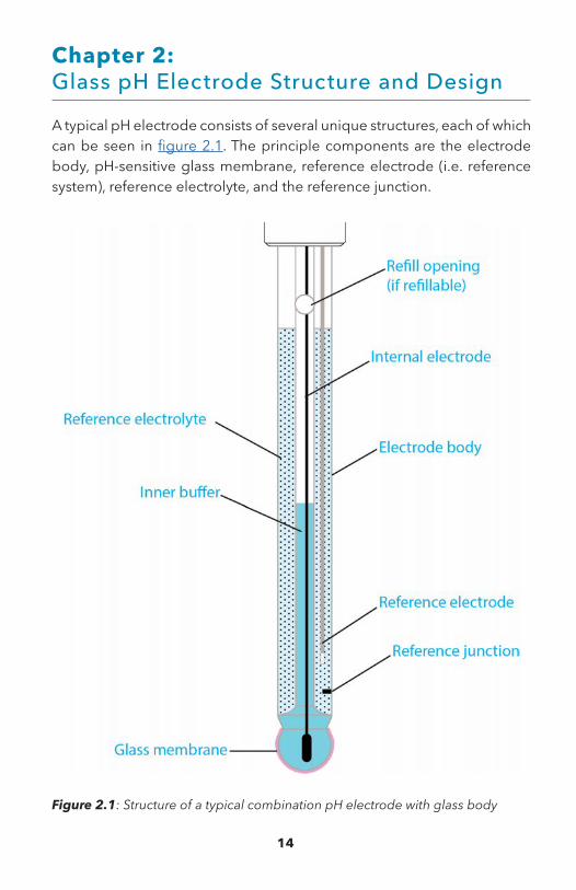
A typical pH electrode consists of several unique structures, each of which can be seen in figure 2.1. The principle components are the electrode body, pH-sensitive glass membrane, reference electrode (i.e. reference system), reference electrolyte, and the reference junction.
Figure 2.1: Structure of a typical combination pH electrode with glass body

15
2.1 Electrode body
The term ‘glass electrode’ is not indicative of the material used to construct the electrode body, as YSI electrodes have either a plastic or glass electrode body. Rather, ‘glass electrode’ is used to describe the membrane material of the sensing electrode (i.e. glass membrane).
Field electrodes are typically constructed from plastic, as plastic body electrodes are more rugged and less likely to crack than glass. YSI offers both glass and plastic body electrodes for the lab, with glass electrodes typically possessing a greater range of operating temperature.
YSI EXO and ProDSS field instruments feature replaceable plastic pH and pH/ORP sensing modules while the rest of the sensor body is titanium (figure 2.2). This design allows for sensing modules to be easily replaced when needed while also ensuring maximum durability in the field.
Figure 2.2: YSI ProDSS pH/ORP sensor
2.2 Glass membrane
The glass used to construct the membrane contains alkali ions (e.g. Na+). These ions, along with H+ ions in solution, form a very thin (~500 nm thick) “gel layer” on the inside and outside of the glass. This layer acts as an ion exchanger of hydrogen ions, as alkali ions from the gel layer are exchanged for hydrogen ions from the sample. Therefore, depending on the pH of the sample, hydrogen ions will move into or out of the gel layer.
With a pH electrode, the glass membrane is fused to an electrode shaft. The membrane is filled with a buffer solution of known pH (typically pH = 7). This electrode design creates an environment with constant binding of H+ ions on the inside of the glass membrane, while the outside of the glass membrane is exposed to the sample where a variable amount of H+ ions exist. The difference in H+ activity creates a potential that is read versus the stable potential of the reference electrode.

16
The membrane shape can vary to ensure optimal moistening of the glass membrane. Sphere (bulb) and cone membrane shapes can be used for most applications, but unique applications may require a specialized membrane, such as the spear tipped YSI TruLine 21 which can penetrate semi-solid media (e.g. meat) and the YSI TruLine 27 with a flat membrane that can be used for surface measurements (e.g. skin). Table 2.1 provides an overview of the different types of pH membranes. Table 2.1: Glass membrane shapes
Shape Property / Application
sphere (bulb)
constant quality, low resistance because of large surface area, for most applications
cone robust, smooth, easy to clean, universally applicable
cylinder shock-proof, for general applications, especially useful for fermenter electrodes
spear high resistance, suitable for penetrating semi-solid media
flat high resistance, shock-proof, easy to clean, suitable for surface measurements
2.3 Reference system
The reference electrode and the hydrogen ISE can be separate electrodes (figure 2.3) or they can be combined into a single electrode for convenience (figure 2.1). The combination-style electrode is very common and all YSI electrodes are of the combination type.
The reference electrode is immersed in a solution of reference electrolyte (section 2.4) that has contact with the sample through the reference junction (section 2.5).
Figure 2.3: Schematic structure of a hydrogen ISE, reference, and voltmeter

17
The most common type of reference electrode used today is the silver/silver chloride (Ag/AgCl) system. Since silver is non-toxic to humans, Ag/AgCl electrodes can be used in medicine and food technology where the poisonous mercury system is prohibited. Disposal is also less critical with Ag/AgCl compared to mercury. Ag/AgCl has a wide range of applications with respect to temperature (up to 140 °C; dependent on electrode) and is therefore also suitable for sterilizable electrodes. Most YSI electrodes feature a Ag/AgCl reference system.
The mercury chloride (Hg/Hg2Cl2) system is the reference system in use for the longest time. This reference system displays the most stable potential in the presence of KCl. However, today it is only used in exceptional cases due to the toxicity of mercury. Also, the reliable temperature range when using mercury chloride is relatively narrow, as Hg2Cl2 begins to degrade at temperatures above 60 oC.
The iodine/iodide system is a relatively new reference system that makes use of the redox pair iodine/iodide. This reference system has several important advantages over other systems.
The iodine/iodide system has a low temperature dependence that allows for rapid response time. Also, the stability of this reference system even at changing temperatures results in superior measurement stability.
The system is metal ion free, a feature that is especially useful when measuring in Tris buffer and protein solutions. Reference systems with metal ions (e.g. Ag/AgCl) will interact with these solutions, ultimately resulting in the reference junction becoming clogged. Electrodes with clogged junctions provide inaccurate results, as the clog prevents the reference system from being in contact with the sample.
The advanced YSI IoLine series of pH electrodes features an iodine/iodide reference system. The unique color of the IoLine reference can be seen in figure 2.4. Figure 2.4:
YSI IoLine

18
2.4 Reference electrolyte
The electrolyte has a connection to the sample through the junction, as it serves to close the electrical circuit in the electrode.
A reference electrolyte must have certain qualities. It must have good electrical conductivity and be chemically neutral. Since some electrolyte will typically leak into the sample during measurement, it is also important the electrolyte not react with the measurement solution.
The ions of an electrolyte solution must also be equally mobile. If ions in the electrolyte solution diffuse at different rates, an electrical potential (i.e. diffusion potential; section 1.6) can form due to the division between the positive and negative charge. This unwanted potential can be quite troublesome when measuring pH. With some ions (e.g. K+ and Cl-), the differences in diffusion speed are small, resulting in a much smaller diffusion potential.
Potassium chloride (KCl) possesses all of these qualities. As a result, KCl is the most commonly used electrolyte solution.
Electrodes can have a gel, polymer, or liquid electrolyte. All YSI field electrodes and some YSI lab electrodes (e.g. TruLine 25 and TruLine 26) feature a gel electrolyte, while most YSI lab electrodes feature a liquid electrolyte that can be refilled. Polymer electrolyte is used in specialized YSI electrodes with a flat tip (TruLine 27) and spear tip (TruLine 21).
Liquid electrolyte
Electrodes with a liquid electrolyte can typically be refilled, thus resulting in a longer electrode life. Therefore, unlike an electrode with gel electrolyte, the electrolyte can easily be drained and replaced if the electrolyte becomes contaminated.
Response time is typically faster with liquid electrolytes. Also, electrodes with liquid electrolyte have fewer limitations in their range of use, as gel and polymer electrolytes have a lower resistance to temperature and temperature changes. Unlike electrodes with liquid electrolyte, the incredibly small outflow rate of gel and polymer electrolyte in strongly

19
acidic, basic, and low-ionic strength solutions can result in measurement errors due to the formation of diffusion potentials.
All YSI refillable lab electrodes utilize 3 M (molar) KCl for the reference electrolyte. However, since the electrolyte is connected to the sample via the junction, some applications require specialized electrolyte solutions.
The YSI IoLine electrode design allows for the use of other electrolytes that meet the demands of the sampling application. For example, if electrolyte is needed that is completely chloride free (i.e. not KCl), another bridge electrolyte, such as 0.6 M potassium sulfate (K2SO4), can be used with the IoLine.
Due to the specialized iodine/iodide reference system of the IoLine, it is critically important the electrolyte be free of silver ions. Also, the conductivity of the electrolyte must be at least 10 mS cm-1. The colored, iodide electrolyte solutions of the IoLine are inside a closed system and cannot be refilled.
Gel and polymer electrolyte
Gel electrolyte still consists of KCl, but a gelling agent is added in order to prevent the electrolyte from readily leaking into the sample via the reference junction during measurement. Since there is virtually no loss of the electrolyte, these electrodes are easier to maintain, as there is no need to refill them with electrolyte. Since they cannot be refilled, electrodes with gel electrolyte have a shorter lifetime than those with liquid electrolyte.
Polymer electrolyte is solid and can directly contact the sample during measurement. Due to the absence of electrolyte outflow, the mobility of all ions is greatly limited. This results in no precipitation of silver at the junction and makes the diffusion of foreign ions into the electrode virtually impossible.
The specialized YSI TruLine 21 and 27 pH electrodes feature the REFERID system, a unique form of polymer electrolyte. These electrodes are low maintenance and are characterized by high resistance to pressure and pressure changes. The REFERID system also features a visible KCl reserve.

20
2.5 Reference junction
The reference junction, also known as a diaphragm, creates electrical contact between the reference system and the solution. Much like the reference electrolyte, the reference junction must possess certain qualities.
Diffusion voltages at the junction are a common measurement error, so the junction plays a major role in the precision of measurements. To keep these disruptive potentials small, the junction must guarantee a relatively large and consistent outflow of reference electrolyte. However, the junction must only be slightly permeable to prevent electrolyte from escaping too quickly. Different junction types have different outflow rates of electrolyte, as can be seen in table 2.2.
In addition to the permeability of the junction, its electrical resistance should be as low as possible and it must be chemically inert.
There are several types of junctions, each with unique characteristics. Depending on the application, a decision must be made for YSI electrodes with liquid electrolytes as to whether a ceramic, ground-joint, or platinum junction best fits the measurement conditions. Table 2.2 provides an overview of the different junction types, including annular gap (TruLine 27) and fiber (TruLine 25 and 26, MultiLab IDS 4110) junctions.
Ceramic junction
A ceramic junction uses the porosity of unglazed ceramic. Ceramic junctions have a KCl outflow rate of ~0.2 mL day-1 and a relatively high electrical resistance (1 kΩ). Diffusion potentials are easily created in measurement solutions with greater ionic strength, as the concentration gradient at the junction is very large. In lower ionic strength solutions, the resistance of the test material may be too high for exact measurements. Both effects are amplified by the low outflow rate, so ceramic junctions are less suitable in such cases. Due to the high risk of blockage of its pores, it is also not suitable for solutions containing suspended particles. Only in measurement solutions that contain oxidizing substances is the ceramic junction superior to the platinum junction.

21
Platinum junction
The platinum junction consists of fine, twisted platinum filaments between which the electrolyte flows out along precisely defined channels. The platinum junction features a very constant outflow and does not easily become blocked. With an outflow rate of ~1 mL day-1 and electrical resistance of ~0.5 kΩ, it has advantages over ceramic junctions. The platinum junction is more sensitive to mechanical stress and is also less than optimal for strongly oxidizing or reducing solutions due to the occurrence of disruptive potentials, but the platinum junction can be used almost universally.
Table 2.2: Types of reference junctions
Junction Type Outflow Rate Properties and applications
Ceramic 0.2 mL day-1
Robust, short response time, pores are easily blocked
Best for general applications, especially useful in solutions with oxidizing substances
Platinum 1 mL day-1
Junction is not easily clogged, fast response time, less diffusion potentials than ceramic, can only clean chemically, sensitive to mechanical stress
Can be used in many applications
Ground joint 3 mL day-1
Very high electrolyte outflow, easily cleaned
Best for solutions with a lot of suspended particles, also useful in high and low-ion solutions
Annular gap None
Symmetrical annular gap, easy handling, resistance to soiling, sample can reach reference system, no cleaning of reference system
Useful for surface measurements when combined with a flat glass membrane
Fiber None
Easy handling, sample can reach reference system, no cleaning of reference system
Can be used for general lab applications and field measurements

22
Ground-joint junction
The ground-joint junction works with the thin gap of the unlubricated ground glass as an outflow opening for the electrolyte. The outflow rate is ~3 mL day-1 and greater. It features a very low electrical resistance (0.1 kΩ). The ground-joint junction is suitable for measurements in contaminated solutions, as it is easy to clean. Due to the high outflow rate, it is suitable for both high and low-ion solutions.
Plastic junction
Junctions constructed from plastic fibers can also be used for special applications. For example, combination electrodes with a plastic shaft often have junctions made from nylon fibers to avoid contamination of the connection hole. For process measurements in solutions that contain fluoride, electrolyte keys with PTFE junctions are used.
2.6 Double and triple junction electrodes
Additional junctions can be used to prevent contamination of the reference system. With this design, the reference electrode is immersed in electrolyte solution within an additional chamber. This additional chamber acts as an extra barrier against contamination while additional junctions are used to ensure the reference system still has contact with the measurement solution. The reference system can still become contaminated by the measurement solution, but the solution must first diffuse through the additional junction(s).
The MultiLab IDS electrodes feature a double-junction design, while the IoLine electrodes are triple junction.
The Silamid reference system used in the Science electrodes is a special type of double-junction electrode that utilizes a unique construction of the silver/silver chloride reference system. Most electrodes featuring a Ag/AgCl system are built with an Ag wire coated with AgCl. Silamid reference systems have a glass tube with the inner part coated with Ag, then filled with AgCl, and plugged with a polyester fiber. This reference system creates greater contact surface area between Ag and AgCl compared to the standard Ag/AgCl wire system, resulting in a reference system that is long lasting and very stable.

23
Chapter 3: Calibration and Measurement Procedures
Obtaining accurate data is dependent upon the practices used when calibrating and taking measurements with a pH electrode.
Before taking any measurements with a pH electrode, it must be properly calibrated using standard buffer solutions. Electrode calibration is necessary in order to establish the slope and zero point of the electrode. Since both of which can change over time, frequent calibration is necessary (section 3.3).
Please consult the instrument manual for specific calibration and data logging procedures.
3.1 Buffers and importance of temperature
Buffers are aqueous solutions whose pH remains virtually unaltered by the addition of small quantities of acids or bases. Buffer solutions are capable of binding hydrogen ions with the addition of acids and releasing hydrogen ions with the addition of bases.
Buffer solutions are often colored to clearly differentiate them from one another during calibration.
Figure 3.1: YSI Buffers (pH 4 is red, pH 7 is yellow, pH 10 is blue)

24
The composition of buffer solutions vary depending on the manufacturer. When selecting a buffer set, care must be taken to ensure they are made according to the formula established by the National Institute of Standards and Technology (NIST). These buffers have pH values of 4.01, 6.86, and 9.18. Alternatively, NIST traceable buffers are also sufficient for use when calibrating. YSI buffers are NIST traceable and are offered in values of pH 4, 7, and 10.
Fresh buffer solutions should always be used. Do not keep buffer solution bottles open, as dust can contaminate the buffer. Also, carbon dioxide in the air can change the pH of basic buffer solutions, so be sure to only briefly open basic buffer solution bottles. Use opened containers of buffer as soon as possible.
Never pour used buffer back into the original buffer container and never immerse the electrode in the original container (i.e. pour solution out of the original container). Although you should never use old buffer solution for calibration, used buffer can be kept for rinsing (section 3.6).
Temperature dependence of the buffer
The pH values of buffer solutions are temperature dependent and the response can vary from manufacturer to manufacturer. As a general rule, basic buffer solutions exhibit stronger temperature effects than acidic ones. Modern pH meters automatically adjust for the respective temperature profile once the buffer series used has been correctly set. For convenience, the YSI TruLab (1310 and 1320) and the YSI MultiLab have over 20 stored buffer sets from different manufacturers.
Table 3.2: Value of YSI pH 10 buffer at different temperatures
oC pH
0 10.34
5 10.26
15 10.12
25 10.00
35 9.90

25
Due to the dependence of pH values on temperature, calibration solutions should have a similar temperature as the expected sampling environment.
Measurements with a temperature sensor
Field and lab pH measurements should always be completed with a temperature sensor. Most YSI lab electrodes feature an integrated temperature sensor, while external temperature sensors (ScienceLine 135 and ScienceLine 136) are available for those that don’t. If a lab measurement is completed without a temperature sensor, the temperature of the solution can manually be set with TruLab and MultiLab instruments.
Figure 3.3: ScienceLine temperature sensors
A certain amount of time is required for the temperature of the electrode and the sample to balance. Calibration and/or measurement should only be completed once the temperature has stabilized.
3.2 Verifying electrode response and slope
To test response time and slope, place the electrode in pH 7 buffer. Record the amount of time it takes for the measurement value to become stable (i.e. measurements no longer moving in one direction). Record the pH measurement and, if possible, the corresponding mV value. Rinse the electrode with DI water and shake dry.
Next, place the electrode in either pH 4 or pH 10 buffer and perform the same stability test. The slope is determined by the difference between the mV readings when the electrode is placed in different buffers. For example, if the measured mV value in pH 7 buffer is -5 mV and the measured value in pH 10 buffer is -172 mV, then a calculated difference of -167 mV can be determined.

26
It should be noted that -167 mV is not a slope value, as the units for pH slope are mV/pH. Therefore, the slope can be calculated as -167 mV / 3 pH units, resulting in a slope of -55.67 mV/pH.
The measured mV difference between pH 7 and pH 10 (or pH 4) must have an absolute value between 165 and 180 mV (i.e. pH slope between -55 mV/pH and -60 mV/pH). If this condition is not met, the electrode should be recalibrated. If the electrode does not produce stable readings within ~2 minutes, electrode cleaning is recommended (Section 4.1).
3.3 Calibration frequency
Perhaps the most common question regarding calibration is how often it should be completed. The frequency of subsequent calibrations depends on the application. Some applications require daily calibration while others may require only weekly or monthly calibration. If possible, calibration at the beginning of each day is best.
More frequent calibration is necessary when measuring in heavily contaminated or low-ion samples. pH electrodes used in strongly acidic and high temperature environments also need to be calibrated more often, as these electrodes will age much faster. This aging process results in a slower electrode response and a change in the electrode slope and zero point (i.e. asymmetry).
To help ensure frequent calibration, many YSI field instruments (e.g. ProDSS, Pro Plus) and YSI lab instruments (TruLab, MultiLab) offer a calibration timer with a user-defined interval in order to automatically remind the user when to calibrate.
3.4 Number of calibration points
The number of calibration points is a common topic of discussion. Most lab and field instruments will allow for calibration with up to 3 buffers.
Single-point calibration
Calibration may be finished after one buffer, resulting in the completion of a single-point calibration. The zero point is determined during a

27
single-point calibration while the electrode slope used is the theoretical Nernst slope (-59.16 mV/pH at 25 °C). It should be noted that a single-point calibration must be completed with pH 7 buffer.
The range of use of single-point calibration is limited, as an electrode calibrated to one point (i.e. pH 7) should only be used to measure within a range of 6.5 pH to 7.5 pH. The pH value obtained may be used to compare to previously obtained measurement results, but is not an absolute value.
Two and three-point calibration
It is best to perform at least a two-point calibration, using pH 7 buffer as one of those points (6.86 for NIST buffer set). Although it is not required for many instruments, it is best to start with pH 7 buffer. For a two-point calibration, the pH buffers used should differ by at least two pH units and should bracket the expected in situ pH conditions. Unless the sample is expected to be above pH 7, basic buffers should not be used, as their pH value changes by absorbing CO2.
Three-point calibrations are typically completed when the sample pH conditions are not well understood. Asymmetry and slope are determined for both two and three-point calibrations.
3.5 Placing a pH electrode in solution
Standard and sample solutions are clearly different, but the procedures for placing an electrode in any solution are the same (e.g. allow the temperature to stabilize before calibrating or recording a measurement, don’t allow the electrode to be stored/soaked in distilled or deionized (DI) water).
Field electrodes
YSI field pH electrodes can become dirty during field sampling, so ensure your electrode is well maintained and in good working condition. Please refer to field electrode cleaning for more information (section 4.1).
Unlike many YSI lab electrodes, YSI field electrodes have a gel electrolyte and thus cannot be refilled. ProDSS and EXO pH and pH/ORP electrodes

28
feature replaceable sensor modules, so there is no need to replace the entire electrode when a replacement pH sensor is needed.
YSI pH electrodes should not be allowed to dry out, so proper storage practices should be utilized (section 4.2). Calibrate the electrode after removing from short-term or long-term storage and/or performing any necessary cleaning steps.
When calibrating and taking measurements, it is important to completely immerse the pH and temperature sensors into the solution. Allow the temperature and pH readings to stabilize before calibrating and recording measurements. pH readings are typically quick and accurate, but measurements may take a longer period of time to stabilize when the electrode is dirty or old. Also, stabilization can take a bit longer in very cold or very warm sampling environments. If the sensor does not stabilize, attempts can be made at cleaning the sensor (section 4.1), although a replacement may be necessary.
Laboratory electrodes
For YSI electrodes featuring a refillable reference, the first step to calibrating and/or taking a measurement is to open the refill opening. Depending on the model, the refill opening is either a slider or a stopper (figure 3.4). The refilling opening must always be open during calibration and measurement!
Figure 3.4: Slider (left) and stopper (right) refill openings for YSI lab electrodes

29
If a plastic watering cap is on the electrode tip, it must be removed before calibration and measurement. A watering cap is included with most YSI electrodes and should be kept for storage. The watering cap should contain 3 M KCl in order to prevent the electrode from drying out during storage. Please refer to the storage section (section 4.2) for more information.
For refillable electrodes, ensure the fill level of the electrolyte is at least 2 cm above the measurement solution level and refill if necessary. There is no harm in completely refilling the electrode with electrolyte. Replace the electrolyte if it has become contaminated (section 4.1).
All YSI refillable electrodes utilize 3 M KCl as the reference electrolyte, although the YSI IoLine can accept other bridge electrolytes (section 2.4).
After removing the watering cap and refilling the electrode with electrolyte, shake the electrode lightly in order to remove any gas bubbles behind the pH membrane.
When placing the electrode in solution, the electrode should be rinsed and placed in solution in a vertical or slightly tilted position. The junction of the electrode must be completely immersed in the measurement solution and only the shaft of the electrode should be immersed.
Table 5.1 provides the junction location for all YSI lab pH electrodes, while figure 3.5 shows the junction location for all YSI TruLine electrodes.
TruLine 25 and 26 TruLine 21 TruLine 27 TruLine 15 and 17
Figure 3.5: Junction locations for the TruLine series of electrodes

30
3.6 Calibration tips and troubleshooting
A few additional procedures should be followed to ensure the electrode is properly calibrated.
Calibration container and electrode rinsing
The electrode and calibration container should be rinsed between calibration points with the solution that follows, as any displaced buffer that is carried over can lead to measurement error. For example, rinse with pH 10 buffer if you have finished calibrating to pH 7 and are preparing to calibrate to pH 10. Alternatively, the electrode can be rinsed with DI water and carefully dabbed dry.
The calibration container should always be clean. The size of the calibration container typically doesn’t matter, as long as the electrode junction is immersed. When calibrating flat glass electrodes (e.g. TruLine pH 21), a 500 mL glass beaker should be used.
Display of mV values
Rather than displaying pH values, it is best to display mV values on the instrument during calibration. Not all instruments have this capability, but instruments such as the YSI MultiLab and TruLab do. During calibration, the observed mV values in each buffer should be as follows:
• Buffer 7 should be -50 to 50 mV.
• Buffer 4 should be 165 to 180 mV away from the buffer 7 mV value in the positive direction.
• Buffer 10 should be 165 to 180 mV away from the buffer 7 mV value in the negative direction.
Figure 3.6: mV display on the YSI MultiLab during pH calibration

31
Calibration troubleshooting
Calibration error is typically due to a worn or dirty electrode and is very rarely due to the pH meter. Contaminated buffer solutions (e.g. pH 10 buffer left open causing pH change due to CO2 influx) can cause calibration error. Figure 3.7 shows the actual pH values of an opened pH 10 buffer and an opened pH 9 buffer. Over the course of 12 hours, the pH of the pH 10 buffer changed by 0.22 pH units and that of the pH 9 buffer changed by 0.02 pH units.
Figure 3.7: pH change in pH 9 (red) and pH 10 (blue) buffers
Issues during calibration may be the result of an aged electrode. Electrodes will generally last 12-18 months, even if they are not being used. Electrodes will age faster if used in extreme operating conditions (strong acids, high temperatures), resulting in a slower electrode response, change in slope, and change in asymmetry (i.e. zero point).
Proper cleaning and storage (chapter 4) can help eliminate pH calibration problems. It is best to establish a routine maintenance schedule, as electrodes typically require weekly or monthly cleaning.
Calibration issues will result if the electrode is physically damaged. The electrode must be replaced if the glass bulb or the electrode body is cracked.
-0.240
-0.220
-0.200
-0.180
-0.160
-0.140
-0.120
-0.100
-0.080
-0.060
-0.040
-0.020
0.000
0
time (hours )
pH
ch
ang
e
6 3 9

32
Check to make sure the electrode has not dried out. Although attempts can be made to recover the electrode (section 4.3), some electrodes will need to be replaced if they have been allowed to dry out.
A faulty temperature sensor can cause calibration errors. The pH measurements will not be accurate if the temperature sensor is out of specification (section 1.6).
If calibration issues continue, attempt to reset the instrument to factory default calibration. Not all instruments have this capability, but some YSI instruments do (e.g. ProDSS).
Finally, never accept out-of-range calibrations. If you accept an out-of-range calibration, your electrode will not calibrate correctly and any pH data collected will not be usable.
3.7 Calibration data
Many modern pH meters, such as the YSI TruLab and MultiLab, will reveal a Good Laboratory Practice (GLP) file with detailed calibration data upon the completion of calibration. This data includes the zero point and slope of calibration (section 1.6).
Some meters can provide the slope in mV/pH and as a percentage of the theoretical Nernst slope at 25 oC (-59.16 mV/pH). This percentage is sometimes referred to as the electrode efficiency.
As an example, let’s consider an electrode slope of -57.10 mV/pH. Equation [9] would be used if the user desired to express this slope in percent.
9 Electrode efficiency = Observed slope * 100 Theoretical slope
With our example, electrode efficiency = -57.10 mV/pH * 100 = 96.52% -59.16 mV/pH

33
After calibrating, the YSI TruLab (1310 and 1320) and MultiLab automatically evaluate the calibration by separately evaluating the zero point and slope (table 3.3). The “worse” of these is used to assign an overall evaluation of the electrode and this assessment appears on the instrument display and in the GLP record.
Table 3.3: TruLab and MultiLab evaluation of the calibration
As an example, let’s use the same electrode slope (-57.10 pH/mV) and a zero point of -12.5 mV. Using table 3.3, the zero point suggests an evaluation of +++ be assigned. However, the slope suggests ++, and since this is the “worse” of the two evaluations, ++ will be assigned to the electrode.

34
Chapter 4: Electrode Maintenance and Storage
4.1 Electrode cleaning
If electrode response time and/or slope is poor, electrode cleaning is recommended. Cleaning is recommended for any dirty or extensively used pH electrodes.
Always recalibrate the electrode after any cleaning procedure.
Before cleaning a pH electrode, it should be noted that distilled or deionized (DI) water should not be used for electrode storage or soaking. This can result in permanent damage to the electrode. However, it is recommended that DI water be used to rinse the electrode when cleaning and/or transferring to another solution.
Also, it is preferable that pH electrodes be chemically, rather than mechanically, cleaned.
Recommended pH electrode cleaning procedures vary based on the type of electrode. YSI field electrodes (e.g. EXO, 556, Pro Plus, ProDSS, IQ SensorNet) require a different cleaning procedure than more delicate YSI laboratory electrodes (e.g. pH1200, TruLine, IoLine, ScienceLine, MultiLab IDS).
Field pH electrode cleaning
To clean a YSI field pH electrode, place the electrode in a warm, mild soap solution (warm tap water with few drops of dish washing soap) for ~15 minutes. Using a cotton swab, carefully clean the glass bulb and junction of any dirt or debris. Rinse with DI water and soak in clean tap water for ~5 minutes. Repeat the test for electrode response (section 3.2).
If electrode performance is still not acceptable, soak the electrode in 1:1 solution of household chlorine bleach and tap water for ~30 minutes. Rinse the electrode thoroughly with DI water and soak for at least 30 minutes in clean tap water with occasional stirring to remove residual

35
bleach from the junction. This procedure can regularly be used to reduce chances of a clogged junction.
If hard deposits have built up on your electrode, you can clean these by soaking the electrode in vinegar or 1M HCl (hydrochloric acid) for ~3 minutes. Ensure proper safety precautions are utilized (e.g. eye protection and gloves). A cotton swab soaked in 1 M HCl may be used to clean the glass bulb. Thoroughly rinse the electrode with DI water and soak the electrode in clean tap water for ~30 minutes.
Soaking the pH electrode in pH 4 buffer for 1-2 days is recommended if electrode performance is still not acceptable. If electrode response continues to be poor after completing these steps, the electrode will likely need to be replaced.
To ensure the correct lab electrode is utilized for your application, be sure to review YSI’s offering of lab pH electrodes before placing an order for a replacement (chapter 5).
Lab pH electrode cleaning
Dirt deposits of any kind on the glass membrane surface or the junction may result in the reduction of the service life of the electrode and inaccurate measurements. To clean these deposits, the following cleaning procedures should be performed:
In the event of inorganic adhesions, place the electrode for ~5 minutes in 0.1 M HCl or 0.1 M NaOH. If the buildup is not removed, the solution should be cautiously heated up to 50 oC before the acid or alkaline concentration is increased.
For organic adhesions, rinse the electrode with organic solvents. The glass membrane can be carefully and briefly wiped with a damp, lint-free, soft cloth. Ensure the organic solvents do not damage the electrode body, especially if the body is constructed from plastic.
For proteins, the electrode should be placed in a pepsin/HCl solution for at least 1 hour.

36
If there are sulfides on the ceramic junction, store the electrode in a thiourea/HCl solution (7.5% in 0.1 M HCl) until the discoloration on the junction has disappeared.
After cleaning, the electrode should be rinsed with DI water and placed in the electrolyte solution for at least 1 hour. Calibration should then be performed.
It may also be necessary to clean the reference electrode. If dirt or other particles are present in the reference electrolyte, remove the old electrolyte and replace with fresh (refillable electrodes only). It may be necessary to repeat until the particles are removed. Using chemicals other than the reference electrolyte is not recommended.
Crystals of KCl in the reference system can be dissolved by heating the electrode in a water bath at 45 oC. The electrolyte must be completely replaced after this heating procedure.
Procedures are also recommended when cleaning different junction types. Clogged ceramic junctions can become usable again after careful rubbing with fine sandpaper or a diamond file. Care must be used in order to ensure the glass membrane is not scratched. Unlike ceramic junctions, platinum junctions must not be mechanically cleaned.
Ground-joint junctions can be made functional again by gently raising and then pushing up the ground socket to the ground core. The refill opening should be open during this procedure. It should be noted that electrolyte will flow out more quickly when completing this procedure. The glass membrane can be cleaned by wiping with an ethanol-soaked, lint-free cloth.
4.2 Electrode storage
All pH electrodes can be permanently damaged if they are improperly stored. Recommendations regarding the storage of a pH electrode vary based on the length of time the electrode will be stored, as well as the electrode type. Regardless of the length of storage or the electrode type, no pH electrode should be allowed to dry out. Also, pH electrodes should never be stored in DI water.

37
Field pH electrode storage
There is no need to remove YSI field pH electrodes from the instrument for short term storage (< 30 days). The electrode must be stored in a 100% water saturated air environment during storage, so frequently check to ensure such an environment is still present.
To create a 100% water saturated air environment, place a small amount of clean tap water in the bottom of the storage cup and install the cup over the sensors. There should be enough water to at least cover the bottom of the cup but do not use an excess amount of water, as the pH electrode should not be immersed in water during storage. Alternatively, a sponge can be wetted with clean tap water and placed in the bottom of the storage container.
Figure 4.1: Short term storage in 100% water saturated air
For long term storage (> 30 days) of YSI field pH electrodes on multiparameter instruments (e.g. ProDSS, Pro Plus, EXO, 6-series sondes), remove the sensor and plug the empty port with a port plug. The electrode can remain installed on single parameter instruments and cables (e.g. pH10A, Pro10, model 60).
Fill the original storage bottle with pH 4 buffer and place the sensor in the storage container. If you no longer have the storage bottle, simply place the sensing portion of the electrode in a pH 4 buffer solution. Do not completely immerse the entire probe in solution (e.g. don’t immerse the connectors on a ProDSS pH sensor).
At the conclusion of long term storage, reinstall the pH sensor and recalibrate.
Figure 4.2: Long term storage of field pH electrode

38
Lab pH electrode storage
YSI lab pH electrodes have different storage requirements than field electrodes. However, much like field electrodes, lab electrodes should never be allowed to dry out.
During short breaks between measurements, the electrode can be placed in a solution of 3 M KCl (Ag+ free). Prior to the next measurement, the electrode should be rinsed with the test sample or DI water. If the electrode has a refillable reference system (i.e. TruLine 15, TruLine 17, IoLine, Science, IDS 4120, and IDS 4130), the refilling opening should be kept open.
For overnight or longer storage, ensure the electrode is clean and fill the plastic cap (i.e. watering cap) that comes with the electrode with reference electrolyte (3 M KCl, Ag+ free). Place the electrode in the watering cap and close the refilling opening (if equipped).
During long storage periods, salt sediments may develop on the watering cap. They do not affect the electrode or measurement results and can easily be cleaned with DI water.
Figure 4.3: YSI lab pH electrode with watering cap
4.3 Conditioning dried pH electrodes
In the event your pH electrode has been allowed to dry out, soaking the electrode in a suitable solution might successfully rehydrate it. YSI field electrodes should be placed in pH 4 buffer and lab electrodes should be placed in a solution of 3 M KCl (Ag+ free). Both lab and field electrodes should be soaked for at least 24 hours and recalibrated afterwards.
If electrode performance is poor after rehydration and subsequent cleaning procedures are unsuccessful, the electrode will likely need to be replaced.

39
Chapter 5: Selecting the Best Electrode
There is not a pH electrode currently available that can be used for every possible application, as there are different requirements for different applications.
There are many applications that a pH electrode may be used for in a lab setting. These unique applications may require a specific shaft material, reference system, junction type, number of junctions, reference electrolyte, or membrane shape. Due to the wide range of lab pH electrodes that are available, this chapter will focus exclusively on choosing the right YSI electrode for the lab.
5.1 YSI lab electrode families
YSI offers many pH electrodes for the lab. The IoLine, TruLine, and Science electrodes feature BNC connection and are designed for use with the YSI TruLab. A BNC adapter (108132Y) also allows these electrodes to be connected to the YSI MultiLab 4010-2 and 4010-3.
YSI IDS pH electrodes feature a digital connector and are designed for use with the YSI MultiLab series of multiparameter instruments.
Figure 5.2: YSI TruLab 1320 (left) and YSI MultiLab 4010-3 (right)

40
TruLine electrodes
The TruLine family of electrodes is designed to be used in typical laboratory applications. This line of electrodes includes durable electrodes with gel electrolyte for general use, liquid electrolyte sensors for more critical measurements, and electrodes with special membranes for unique applications.
Figure 5.3: YSI TruLine electrodes
IoLine electrodes
The IoLine is the most advanced electrode YSI offers and is specifically designed for use with Tris buffers and protein solutions. Unlike commonly used Ag/AgCl reference systems, the unique iodine/iodide reference system of the IoLine prevents clogging of the reference junction when used in Tris buffer and protein solutions. A micro version of the IoLine is also available for applications with small sample sizes.
The IoLine can be used in many other applications besides those with Tris buffers and protein solutions. The iodine/iodide reference system and the platinum junction provide excellent stability, fast response times, high accuracy, and the ability to be used in nearly any sample. The IoLine can also be used in a wide-range of temperatures and the triple junction design increases measurement security.
Figure 5.4: YSI IoLine electrodes

41
Science electrodes
The Science electrodes are designed for use in unique applications that require a particular junction. All Science electrodes feature the Silamid reference system. This double junction reference system provides fast and stable measurements and allows for a very long electrode life. A ground-joint junction with a fast electrolyte outflow is specifically designed for samples with a lot of solids and solutions with low ionic strength. A platinum junction version is also available for applications that do not require an electrolyte outflow as high as the ground joint junction.
Figure 5.5: YSI Science electrodes
MultiLab IDS electrodes
YSI intelligent digital sensors (IDS) electrodes feature a double junction reference system and are available in gel-filled or liquid electrolyte versions. These electrodes have digital connectors and are specifically designed for use with the YSI MultiLab system. These electrodes are similar to the TruLine electrodes, although they do provide increased measurement security compared to the single-junction TruLine series.
Figure 5.6: YSI IDS 4110 electrode

42
Electrode Item Number Connector Shaft Refillable Temp
SensorReference
SystemJunction
TypeNumber of Junctions
Membrane Shape
Reference Electrolyte
IDS
4110 103740Y Digital Plastic (PPE/PS) No Yes Ag/AgCl Fiber Double Cylindrical Gel, KCl
4110-3 103741Y Digital Plastic (PPE/PS) No Yes Ag/AgCl Fiber Double Cylindrical Gel, KCl
4120 103750Y Digital Plastic (Polyamide) Yes Yes Ag/AgCl Ceramic Double Cylindrical Liquid, 3 M KCl
4130 103780Y Digital Glass Yes Yes Ag/AgCl Platinum Double Conical Liquid, 3 M KCl
IoLi
ne IoLine 400358 BNC Glass Yes Yes Iodine/Iodide Platinum Triple Sphere (bulb) **Liquid, 3 M KCl
IoLine Micro 400359 BNC Glass Yes Yes Iodine/Iodide Platinum Triple Cylindrical **Liquid, 3 M KCl
TruL
ine
pH 15 400350 BNC Glass Yes Yes Ag/AgCl Platinum Single Conical Liquid, 3 M KCl
pH 17 400351 BNC Glass Yes No Ag/AgCl Platinum Single Conical Liquid, 3 M KCl
pH 25 400353 BNC Plastic (PPE/PS) No No Ag/AgCl Fiber Single Cylindrical Gel, KCl
pH 26 400352 BNC Plastic (PPE/PS) No Yes Ag/AgCl Fiber Single Cylindrical Gel, KCl
pH 21 400357 BNC Plastic (PPE/PS) No No Ag/AgCl Hole Single Spear tip Polymer
pH 27 400354 BNC Glass No No Ag/AgCl KPG annular gap Single Flat Polymer
Scie
nce pHT-Pt 400360 BNC Glass Yes Yes *Silamid® Platinum Double Sphere (bulb) Liquid, 3 M KCl
pHT-G 400361 BNC Glass Yes Yes *Silamid® Ground Joint Double Sphere (bulb) Liquid, 3 M KCl
pHT-Micro 400362 BNC Glass Yes Yes *Silamid® Platinum Double Cylindrical Liquid, 3 M KCl
5.2 Electrode Selection and Application Guides
Table 5.1: YSI Lab pH Electrode Selection Guide

43
Electrode Item Number
Temp. Sensor
Connector
pH Range
Temp. Range Length Diameter
*Minimum Immersion
Depth
Cable Length (meter)
Warranty (months)
IDS
4110 103740Y Included in digital connection 0 … 14 0 … 80 °C 120 mm 12 mm 12-13 mm 1.5 12
4110-3 103741Y Included in digital connection 0 … 14 0 … 80 °C 120 mm 12 mm 12-13 mm 3 12
4120 103750Y Included in digital connection 0 … 14 0 … 80 °C 120 mm 12 mm 12-13 mm 1.5 12
4130 103780Y Included in digital connection 0 … 14 0 … 100 °C 120 mm 12 mm 16-18 mm 1.5 12
IoLi
ne
IoLine 400358 Banana plug 0 … 14 -5 … 100 °C 120 mm 12 mm 15-16 mm 1 12
IoLine Micro 400359 Banana plug 0 … 14 -5 … 100 °C top: 70 mmbottom: 130 mm
top: 12 mm bottom: 6 mm 10-11 mm 1 12
TruL
ine
pH 15 400350 Banana plug 0 … 14 0 … 100 °C 120 mm 12 mm 16-18 mm 1 12
pH 17 400351 N/A (no temp. sensor) 0 … 14 0 … 100 °C 120 mm 12 mm 16-18 mm 1 12
pH 25 400353 N/A (no temp. sensor) 0 … 14 0 … 80 °C 120 mm 12 mm 12-13 mm 1 12
pH 26 400352 Banana plug 0 … 14 0 … 80 °C 120 mm 12 mm 12-13 mm 1 12
pH 21 400357 N/A (no temp. sensor)
2 … 13 0 … 80 °C top: 65 mmbottom: 25 mm
top: 15 mmbottom: 5 mm 11-12 mm 1 12
pH 27 400354 N/A (no temp. sensor) 2 … 13 0 … 50 °C 120 mm 12 mm N/A
(flat membrane) 1 12
Scie
nce
pHT-Pt 400360 Banana plug 0 … 14 -5 … 100 °C 170 mm 12 mm 17-19 mm 1 12
pHT-G 400361 Banana plug 0 … 14 -5 … 100 °C 170 mm 12 mm 12-14 mm 1 12
pHT-Micro 400362 Banana plug 0 … 14 -5 … 100 °C top: 70 mmbottom: 130 mm
top: 12 mm bottom: 5 mm 10-11 mm 1 12
YS
I LA B O R A T O R Y pH
RE
PEATA B LE. T RUSTE
D.
* Minimum immersion depth is the distance from the tip of the membrane to the outer junction. The junction must always be completely immersed when taking a measurement.

44
Table 5.2: YSI Lab pH Electrode Application Guide
Electrode Series IDS IoLine TruLine Science
4110
4120
4130
3 in
1
pH
15
pH
17
pH
25
pH
26
pH
T-Pt
pH
T-G
Application
Che
mis
try
Acid, extreme l l l l l
Emulsions, water-based l l l l l
Non-aqueous liquids l l l l l
Oil/water-emulsions l l l l l
Organic liquids l l l
Sulfide containing liquids
l l l
Ind
ustr
ial
Boiler feedwater l l l l l
Cooling water l l l l l
Cutting oil emulsions l l l l l
Dyeing solutions l l l l l
Electroplating baths l l l l l
Electroplating waste-water
l l l l l l l
Paper extract l l l l l
Viscose l l
Wat
er
Aquarium water l l l l l l l l
Condensate l l l l l
Deionized water (DI water)
l l l l l
Drinking water l l l l l l l l
Salt solutions l l
Suspensions l l l
Swimming pool l l l l l l
Wastewater, general l l l l l l l l
Fiel
d
Mea
sure
men
ts
Groundwater l l l l l l l l
Lake water l l l l l l l l
Rain water l l l l l l l l
Seawater l l l l l l l l
Soil extract l l l
Stream l l l l l l l l

45
Electrode Series IDS IoLine TruLine Science
4110
4120
4130
3 in
1
pH
15
pH
17
pH
21
pH
27
pH
T-Pt
pH
T-G
Application
Co
smet
ics
Creme l l l l l l l
Hair dye l l l l l
Hair gel l l l l
Hair mousse l l l l l
Lotions l l l l l
Make-up l l l l l l
Mouth wash l l l l l
Shampoo
Shaving cream l l l l l
Sun lotion l l l l l
Tooth paste l l l l l
Pain
ts/A
rt
Etching and degreasing baths
l l l l l
Fixing baths (photography)
l l l l l
Ink l l l
Paint/varnish, water-soluble
l l l l l
Photographic developer
l l l
Varnish, water-based l l l l l
Solid
s /
Surf
aces
Leather (surface) l
Paper l
Skin (surface) l
Solids (penetration) l
Solids (surface) l
Textiles l
Was
hing
Ag
ents
Cleaning agent (e.g. ammonia, etc.)
l l l l l
Detergents l l l l l
Dishwashing liquid l l l l l
Disinfectant (e.g. bleach, etc.)
l l l l l
Soap solution l l l l l
Surfactant solution l l l l l

46
Electrode Series IDS IoLine TruLine Science
4110
4120
4130
3 in
1
pH
15
pH
17
pH
25
pH
26
pH
21
pH
27
pH
T-Pt
pH
T-G
Application
Dri
nks
Pro
duc
tion Beer l l l l l l l l
Fruit juice l l l l l
Lemonades/soda l l l l l l l l
Mineral water l l l l l l l l
Spirits l l l l l
Vegetable juice l l l l l
Wine l l l l l
Foo
d
Bread/dough/pastry l
Coffee extract l l l l l
Extracts l l l
Fish l
Grease l l l
Honey l
Jam/marmelade l l l l l
Margarine l l l l l
Mayonnaise l l l
Meat l
Sausage l l
Vinegar l l l
Dai
ry
Butter l l l l
Cheese l l l l
Cream l l l l l
Milk l l l l l
Yogurt l l l l l
Ag
ricu
lture
Fertilizer solution l l l l l l l
Fruit l
Liquid manure l l l l l
Vegetables l l

47
Electrode Series IDS IoLine TruLine Science
4130
3 in
1
Mic
ro
pH
15
pH
17
pH
21
pH
27
pH
T-Pt
pH
T-G
pH
T M
icro
Application
Phar
mac
y, B
iolo
gy,
Bio
tech
nolo
gy,
M
edic
ine,
Mic
rob
iolo
gy
Agar-agar gel l l
Bacteria cultures l l l l l l l
Enzyme solution l l l l
Gastric juice l l l l
Infusion solutions l l l l l l
Precision mea-surement
l l l l
Protein containing liquid
l l l l l
Saliva l l l
Serum l l l l l
Small vessels/sample
l l
Tris Buffer l l
Urine l l l l l l
Vials l l
YS
I LA B O R A T O R Y pH
RE
PEATA B LE. T RUSTE
D.
Figure 5.7: IoLine being used to check pH during the production of immunoassay solutions

48
Final words
We hope you have found the information in this brief pH handbook to be informative and helpful. Please visit YSI.com for other pH-related content designed to help you obtain the best possible data.
YSI manufactures rugged, reliable, and highly accurate equipment for the measurement of many parameters, including pH. However, our expertise reaches much further than technological innovation, as we are also focused on providing unparalleled customer service and support.
For assistance in selecting the right instrument for your application, please contact YSI’s knowledgable Technical Support Staff by calling 800-897-4151 (+1 937-767-7241) or by sending an email to [email protected]. In addition, YSI has offices located around the world ready to assist you with selecting an instrument, ordering replacement parts, or providing repair services. Please visit YSI.com for a complete list of our global offices.
YS
I LA B O R A T O R Y pH
RE
PEATA B LE. T RUSTE
D.

Calibration
Your results are only as good as your last calibration.
1. Use fresh buffers. Buffer precision degrades over time. The pH of alkaline buffer solutions can quickly change when exposed to air. Follow the manufacturers “use by” dates.
2. Rinse clean beaker with buffer solution before filling.
3. Rinse the sensor with DI water and/or the next calibration buffer. Blot dry.
4. A two point calibration is typically sufficient. We advise using pH 4 and 7 buffers (or NIST 4.01 and 6.87 buffers) since alkaline buffers are less stable.
5. Never reuse buffers. 6. Calibrate at or near the same temperature of the sample being measured.
7. Use NIST traceable, single-use or DIN buffers for highest accuracy and reliability.
Proper Use
A pH sensor is a highly technical, precision instrument.
1. Open the refilling port if present. Keep open during measurements.
2. Refill electrolyte if necessary; the level of electrolyte should be at least 2 cm above the sample.
3. Ensure that the junction is completely submerged.
5. Rinse with DI water and/or with the next sample between measurements.
6. Ensure a homogenous and temperature stable sample. Stirring may be necessary.
7. Avoid contact with the pH membrane to prevent damaging the pH measuring surface. Never use as a stirrer.
Page 1 of 2
Lab pH Quick Tips
See Chapter 3 of the YSI pH Handbook for additional calibration and measurement tips
YS
I LA B O R A T O R Y pH
RE
PEATA B LE. T RUSTE
D.

Storage
Perhaps the main contributor to the life, speed and precision of your pH electrode.
1. Always store your combination pH electrode in the same solution used for the reference electrolyte (typically 3 M KCl). Use an airtight storage vessel such as a plastic storage cap included with many electrodes.
2. Between samples, electrodes can be stored in pH 4 or 7 buffer, storage solution, or in clean water.
3. Never store in deionized (DI) water. This will diminish the life and accuracy of your combination pH electrode.
4. Close refilling port (if applicable) and store upright in a cool, dry place.
5. Never allow the electrode to dry out. Rehydrating in pH 4 buffer for 24 hours may recondition the sensor. Calibrate to ensure proper functionality.
Maintenance
Just as with a vehicle, maintenance depends on how it is used and how often.
1. When there are visible signs of contaminates or your readings are inconsistent after a calibration, it’s time for maintenance.
2. Clean according to the instructions for your sensor.
3. Check pH measuring bulb for scratches, abrasions, cracks or nicks. This could cause irregular readings.
4. Refill or exchange the reference electrolyte. Empty, rinse with DI water, rinse with reference electrolyte, refill with reference electrolyte.
5. Air bubbles can cause erratic readings. It is okay to shake a sensor to remove air bubbles from within the sensor.
Page 2 of 2
Lab pH Quick Tips
See Chapter 4 of the YSI pH Handbook for additional storage and cleaning tips
YS
I LA B O R A T O R Y pH
RE
PEATA B LE. T RUSTE
D.
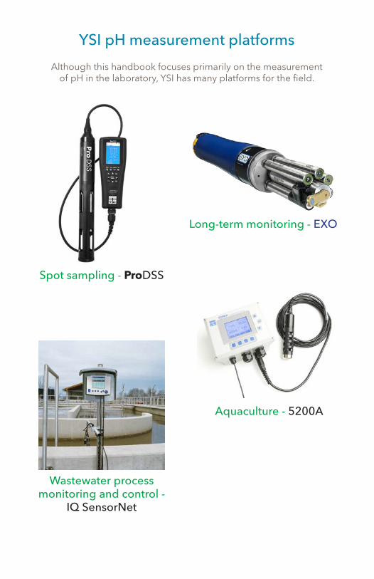
YSI pH measurement platforms
Although this handbook focuses primarily on the measurement of pH in the laboratory, YSI has many platforms for the field.
Long-term monitoring - EXO
Spot sampling - ProDSS
Aquaculture - 5200A
Wastewater process monitoring and control -
IQ SensorNet

YSI1700/1725 Brannum LaneYellow Springs, OH 45387Tel: 800-765-4974 (937-767-7241)E-Mail: [email protected]: YSI.com
Xylem |ˈzīləm|
1) The tissue in plants that brings water upward from the roots;2) a leading global water technology company.
We’re a global team unified in a common purpose: creating innovative solutions to meet our world’s water needs. Developing new technologies that will improve the way water is used, conserved, and re-used in the future is central to our work. We move, treat, analyze, and return water to the environment, and we help people use water efficiently, in their homes, buildings, factories and farms. In more than 150 countries, we have strong, long-standing relationships with customers who know us for our powerful combination of leading product brands and applications expertise, backed by a legacy of innovation.
For more information on how Xylem can help you, go to www.xyleminc.com
YSI is a registered trademark
© 2015 YSI, a xylem brand
W78 August, 2015
$15.00
presented by