the physics of polarization - hao.ucar.edu physics of polarization ... an operational definition . i...
TRANSCRIPT

The Physics of Polarization
Egidio Landi Degl’Innocenti
Department of Physics and Astronomy
University of Florence, Italy
IAU Symposium 305: “Polarimetry: from the sun to stars and
Stellar environments”, Punta Leona, Costarica
November 30, 2014

Introduction I
Polarization is an important physical property of electro-
magnetic waves which is connected with the trasversality
character, with respect to the direction of propagation, of
the electric and magnetic field vectors.
Introduction II
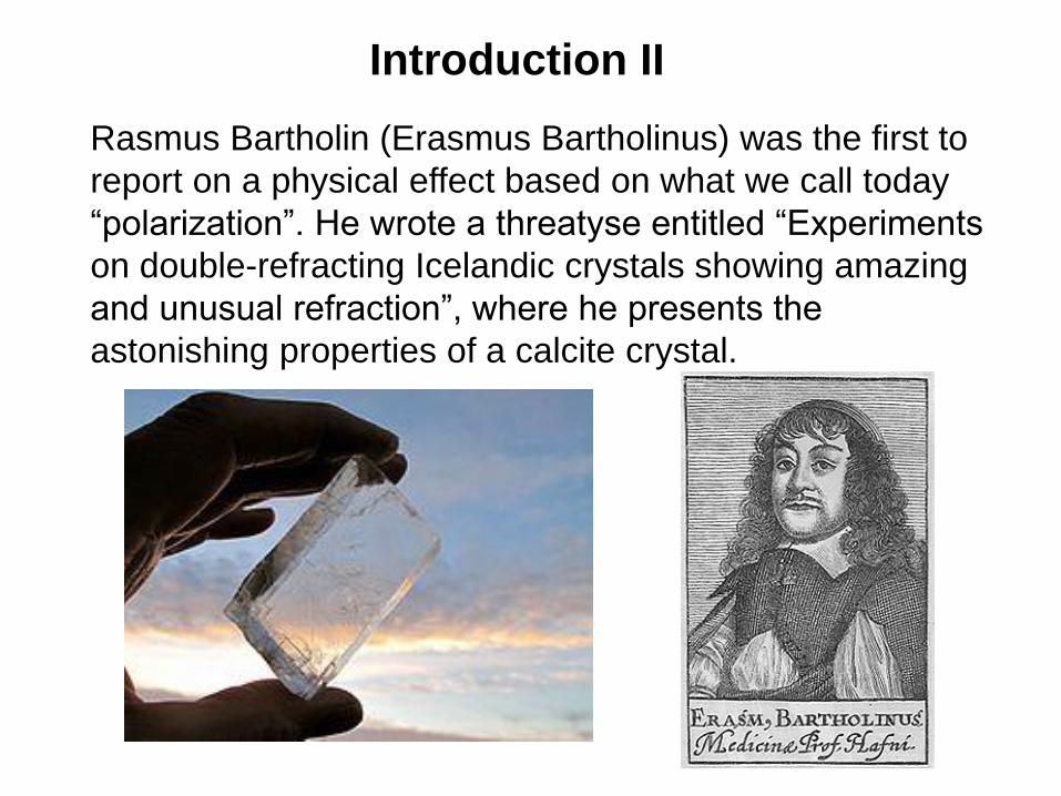
Rasmus Bartholin (Erasmus Bartholinus) was the first to
report on a physical effect based on what we call today
“polarization”. He wrote a threatyse entitled “Experiments
on double-refracting Icelandic crystals showing amazing
and unusual refraction”, where he presents the
astonishing properties of a calcite crystal.

Introduction III
Reflecting on Bartholin’s experiments, Christiaan
Huyghens in his “Threatyse on light” and Isaac Newton in
his “Optics”, though working within the framework of two
completely different theories of light (undulatory and
corpuscular, respectively) arrived to the conclusion that
light should have some “transversality” property (not yet
called polarization).
Newton Huyghens

Introduction IV
After many years from Huyghens and Newton, the
french physicist Etienne Louis Malus that introduces in
the scientific literature the word “polarization”. In his
paper “Sur une proprieté de la lumière réfléchie” (1809)
Malus proves that polarization is an intrinsic property of
light and demonstrates that polarization can be easily
produced through the phenomena of reflection and
refraction. He also proves the famous cos2θ law today
known as “Malus law”.

Introduction V
The work of Malus opens the way to the achievemets of
another french physicist, probably the most renowned
optician of all times, Augustin Fresnel, who definitely
proves the transversality of light. In his work “Mémoires
sur la réflexion de la lumière polarisée”, Fresnel proves
his famous laws concerning the polarization properties of
light reflected and transmitted at the surface of a
dielectric.

Introduction VI
The story of polarization goes on with several significant
contributions by François Arago, Jean-Baptiste Biot
(optical activity in crystals), David Brewster (today known
for the “Brewster angle”), William Nicol (who builds the
first polarizer, the so-called “Nicol prism”), and Michael
Faraday (who discovers the “Farady effect”).
Arago Brewster Nicol (right) Fraday

Introduction VII
However, it is only in 1852 with the fundamental work of
George Stokes entitled “On the composition and resolution
of streams of polarized light from different sources”, that
the desricption in mathematical terms of polarized radiation
becomes fully consistent. Stokes introduces four
quantities, today know as the “Stokes parameters”, that
have proven to be quite successful for the description of
the polarization properties of a radiation beam.

Introduction VIII
At the middle of the XIX century, the phenomenon of
polarization is thus fairly well understood, but it is
necessary to wait for more than 50 yeras before the first
astronomical application of polarization. In 1908 Hale
succeeds in observing the spectrum of a sunspot in two
opposite direction of circular polarization and, from the
observed shift of the spectral lines deduces the existence
of a magnetic field on an astronomycal object, the sun.

Description of polarization I
Consider an electromagnetic, monochromatic plane wave
of angular frequency ω that is propagating in vacuum along
a direction that we assume as the z-axis of a right-handed
reference system. At a given point of space, the electric
and magnetic field vectors of the wave oscillate in the x-y
plane according to equations of the form
where E1, E2, �ϕ 1, and �ϕ 2 are constants. These
oscillations combine in such a way that the tip of the
electric filed vector describes an ellipse.

Description of polarization II
Obviously, the polarization ellipse can degenerate into a
segment (and one then speaks of linear polarization)
or it can degenerate into a circle (and one then speaks
of circular polarization).

Description of polarization III
The description now given is however valid only for a
plane, monochromatic wave which goes on indefinitely
from t = -∞ to t = ∞. This is obviously a mathematical
abstraction which, in general, has little to do with the
physical world. A much more realistic description of a
beam of radiation can be given only in terms of a
statistic superpositions of many wave-packets each
having a limited extension in space and time. The
beam thus loses its property of being monochromatic,
becoming a quasi-monochromatic wave. Moreover, if
the individual wave-packets do not share the same
polarization properties, the polarization ellipse varies,
statistically, in time.

Description of polarization IV
The statistical decription of polarization, introduced by
Stokes, implies considering the statistical averages of
bilinear products of the electric field components along the
x and y axes and forming from them four independent
linear combinations:
wher
e .

Description of polarization V
The quantities now introduced are called the Stokes
parameters. This is a pictorial representation and, at the
same time, an operational definition
.
I
Q
U
V
Through the Stokes parameters it is possible to give a
coherent definition of the polarization properties of an
arbitrary beam of radiation.

Polarization and optical devices I
The operational definition given above implies the use of
two fundamental optical devices: the polarizer and the
retarder. From the polarimetric point of view any optical
device is characterized by a 2 x 2 matrix of the form
.
relating the complex electric field components of the exit
beam to the corresponding components of the input beam.
The matrix appearing in this equation is called a Jones
matrix. For a train of N optical components, the Jones matrix
of the train is given by the product of N Jones matrices.

Polarization and optical devices II
In particular, for an ideal polarizer one has
.
so that a single component of the electric field survives.
Whereas for an ideal retarder
The two components of the electric field along the directions
of the “fast” and the “slow” axis are dephased. The phase
difference δ is called the retardance. When δ = π/4, the
retarder is called a quarter-wave plate.
Polarization and optical devices III
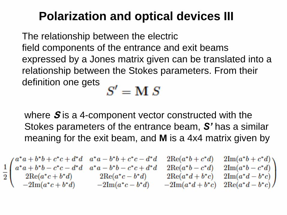
The relationship between the electric
field components of the entrance and exit beams
expressed by a Jones matrix given can be translated into a
relationship between the Stokes parameters. From their
definition one gets
where S is a 4-component vector constructed with the
Stokes parameters of the entrance beam, S’ has a similar
meaning for the exit beam, and M is a 4x4 matrix given by
Polarization and optical devices IV
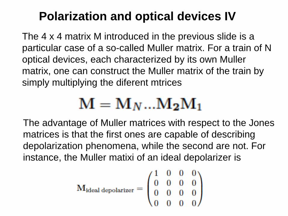
The 4 x 4 matrix M introduced in the previous slide is a
particular case of a so-called Muller matrix. For a train of N
optical devices, each characterized by its own Muller
matrix, one can construct the Muller matrix of the train by
simply multiplying the diferent mtrices
The advantage of Muller matrices with respect to the Jones
matrices is that the first ones are capable of describing
depolarization phenomena, while the second are not. For
instance, the Muller matixi of an ideal depolarizer is

Polarization and optical devices V
The calculus based on Jones matrices and Mueller
matrices has a large variety of applications in physics and,
more particularly, in astronomy. It is at the base of the
design of polarimeters operating in the different regions of
the electromagnetic spectrum, from the ultraviolet to the
infrared. In many cases, one can even define the Mueller
matrix of a telescope by analyzing the properties of each
of its optical devices and then deducing the resulting
matrix as the product of the matrices of each device. The
knowledge of the Muller matrix of a telescope is essential
for a proper calibration of the polarization observed in the
focal plane of a telescope.

Polarization and physical phenomena
Reflection and refraction I
The simplest and most common physical phenomenon
where polarization processes enter into play is the
ordinary reflection of a pencil of radiation on the surface of
a dielectric (or of a metallic) medium. This phenomenon,
which is generally accompanied by the related
phenomenon of refraction inside the medium, is described
by the so-called Fresnel equations. In a modern approach
these equations can be derived from Maxwell’s equations,
though Fresnel, obviously, had no idea of them ….
(Maxwell was Born 4 years after the death of Fresnel).
Polarization and physical phenomena
Reflection and refraction II
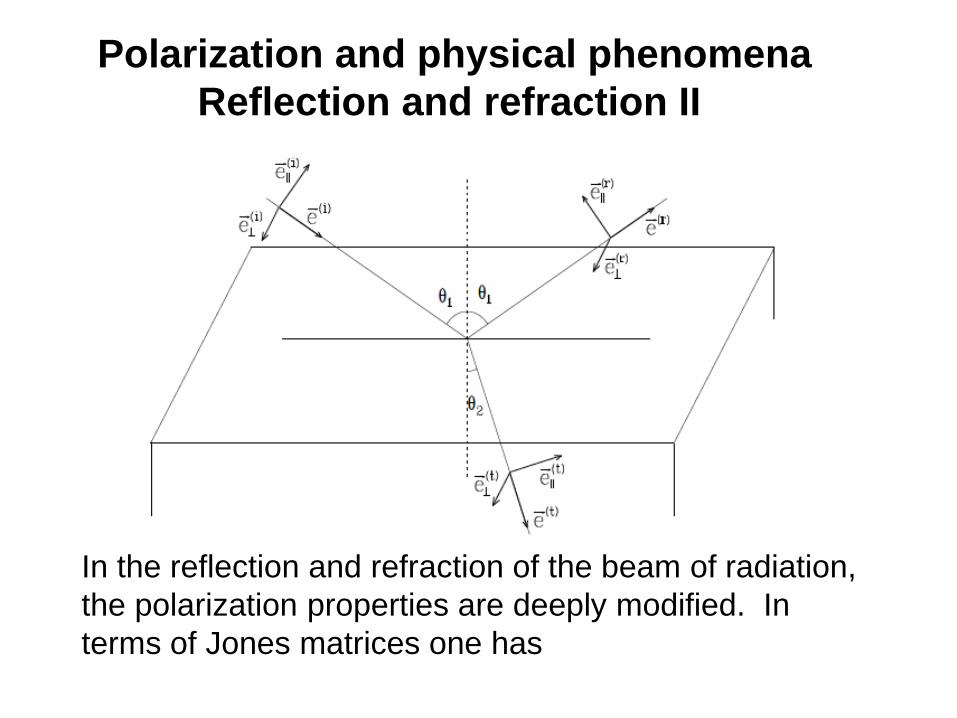
In the reflection and refraction of the beam of radiation,
the polarization properties are deeply modified. In
terms of Jones matrices one has

Polarization and physical phenomena
Reflection and refraction III
Reflected beam
Refracted beam
with (Snell’s law)

Polarization and physical phenomena
Reflection and refraction IV
For reflection on water, for instance, the coefficients are
shown in this graph. Note that for a particular angle (the
Brewster angle) rpar = 0. The reflected beam is totally polarized

Polarization and physical phenomena
Reflection and refraction V
Left image: without polarizing filter
Right image: with polarizing filter

Polarization and physical phenomena
Reflection and refraction VI
Radiation propagating from inside a dielectric to air can
suffer the phenomenon of total internal reflection. In such
reflection a dephasing occurs between the parallel and
perpendicular components of the incident electric field. This
allows to construct an instrument capable of transforming
linear into circular polarization, such as the Fresnel rhomb.

Polarization and physical phenomena
Dichroism and anomalous dispersion I
Though the etymology of the word is rather misleading,
dichroism is a typical phenomenon of anisotropic media
which consists in the fact that the absorption properties of
the radiation propagating inside such media depends on
polarization. Anomalous dispersion is a related phenomenon
due to the dephasing of the two components of the electric
field vector.
The two phenomena can be “unified” by thinking about the
two complex amplitudes Ea and Eb of the electric
field along two orthogonal states of polarization. Dichroism
is connected with the differential attenuation of the
modulus of Ea and Eb during the propagation, whereas
anomalous dispersion is connected with the dephasing of
the same quantities.

Polarization and physical phenomena
Dichroism and anomalous dispersion II
A description of these phenomena for a general anisotropic
medium can be given by introducing the principal axes of
the medium, characterized by three unit vectors uα (α=1, 2,
3), and the corresponding indexes of refraction nα, which
are, in general, complex numbers. A wave of angular
frequancy ω, polarized along the direction uα, propagates
within the medium according to the equation
By considering the bilinear products of the field
components, with some algebra it is possible to write a
transfer equation for the Stokes parameters encompassing
the phenomena of dichroism and anomlaous dispersion.

Polarization and physical phenomena
Dichroism and anomalous dispersion III
The symmetric part of the matrix describes dichroism whereas
the antisymmetric part describes anomalous dipsersion.

Polarization and physical phenomena
Dichroism and anomalous dispersion IV
Where the quantities G are connected to the indeces of
refraction and to the unit vectors by the equation
Particularly important is the term ρV appearing in the
transfer equation of the previous slide. This term produces,
in the propagation, the continuous transformation of the
Stokes parameter Q in the Stokes parameter U and
viceversa. The result is the rotation of the plane of
polarization of light of a quantity which is proportional to the
path-length.

Polarization and physical phenomena
Dichroism and anomalous dispersion V
Optical activity was discovered by Arago in quartz crystals,
by Biot in solutions of inorganic and organic substances
(including sugar) and by Faraday in media pervaded by a
magnetic field (Faraday effect).
Polarization in everyday life I
Polarization is a rather obscure concept for the man on the
street. This is not because polarization phenomena are not
present in the world around us, but just because the
human eye (differently from the eye of other living beings)
is practically insensitive to the polarization of light, though
some minor effects, due to the presence of a blue,
dichroicly absorbing pigment in the macula lutea can
indeed be observed under particular conditions
(Heidinger's brush).
Polarization in everyday life II
We have already seen that the light reflected from a
dielectric surface is linearly polarized, the direction of
polarization being the perpendicular to the plane of
incidence. It then follows that sunlight refected over the
surface of the sea (or of a lake) is also linearly polarized
and that such reflections can be extinguished, to a large
extent, by means of a polarizing
filter whose transmission axis is set along the vertical. This
can be accomplished by wearing a particular type of
sunglasses that can be commonly found in commerce and
are usually referred to as Polaroids (Polaroid is a registered
mark). The “lenses" of these sunglasses are nothing but
polarizing
filters suitably oriented by the manufacturer in such a way
that the transmission axis coincides with the vertical axis.
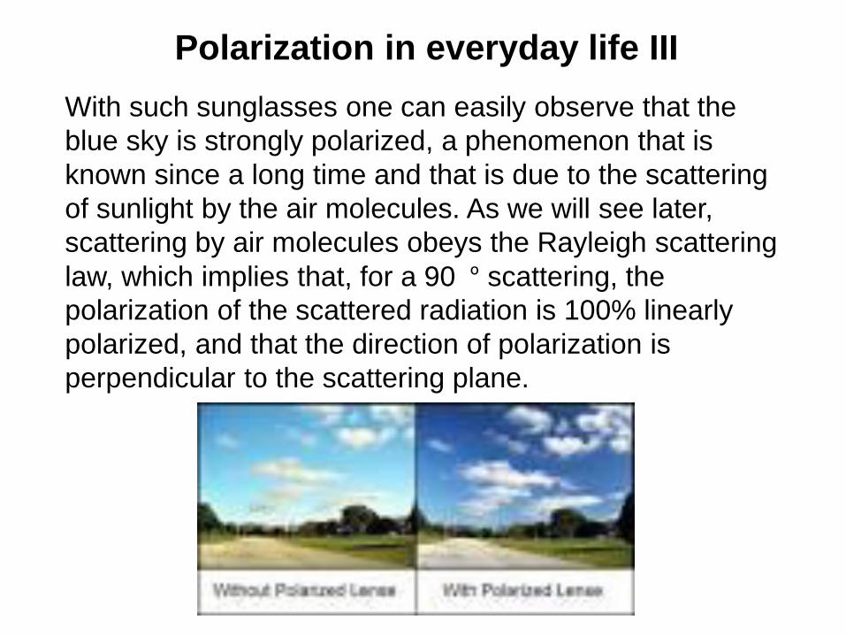
Polarization in everyday life III
With such sunglasses one can easily observe that the
blue sky is strongly polarized, a phenomenon that is
known since a long time and that is due to the scattering
of sunlight by the air molecules. As we will see later,
scattering by air molecules obeys the Rayleigh scattering
law, which implies that, for a 90�º scattering, the
polarization of the scattered radiation is 100% linearly
polarized, and that the direction of polarization is
perpendicular to the scattering plane.

Polarization in everyday life IV
The polarization of the ble sky is an important physical
phenomenon that is indeed used by several living beings
(some species of insects, in particular) as a practical
mean of orientation. Obviously, these insects are
provided of a particular kind of eyes which allow them to
observe the direction of polarization of the sky and to
recover the sun's position. It has also been suggested
that the navigators of Viking ships used a piece of
Iceland spar to help them in
finding the sun's direction in the heavily cloudy, northern
skies of Scandinavia.

Polarization in everyday life V
Polarization also shows up in other meteorological
phenomena, like in the rainbow and in halos. The rainbow
is produced by the refraction of the solar radiation by
droplets of water. The primary arch is due to a process of
refraction (the solar rays enter the droplet), an internal
reflection), and a
final refraction (by which the solar ray exits the droplet). An
analysis based on the Fresnel equations allows to deduce
that the rainbow is linearly polarized, the polarization
direction being parallel to the bow, and the fractional
polarization being given by

Polarization in everyday life VI
Substituting the value of n, it is found that the polarization
is parallel to the arch and is of the order of 93%.
δ ≈ 42º

Polarization in everyday life VII
The halo, a somewhat less known phenomenon which
shows up when ice crystals are present in the upper
atmosphere, is due to the refraction of sunlight inside the
crytals themselves. It shows up as a luminous circle
around the sun located at a distance of about 22�º. The ice
crystals have the shape of long prisms having an exagonal
cross section. A simple application of the Fresnel
equations shows that the halo is linearly polarized, the
polarization being directed perpendicularly to the halo, and
the fractional polarization being given by

Polarization in everyday life VIII
Substituting the value of the index of refraction of ice
(n=1.31) one finds that the halo is much less polarized than
the rainbow (only 4%). The direction of polarization is
perpendicular to the halo.
Polarization in everyday life IX
Finally, it is important to remark that polarimetry has a very
large number of technological applications in many
practical aspects of life. An example is the use of
polarimetric techniques to measure the quality of sugar.
The sugar is diluted in a solution and the rotatory power of
the solution is then measured through an instrument that is
called a saccharimeter. From the rotatory power measured
it is easy to recover the quality (saccarosium content) of the
sugar contained in the solution. Another example concerns
security systems that turn on when a beam of light is
interrupted. By encoding the light beam and the receiver
according to a particular state of polarization, it becomes
almost impossible to substitute the originary beam with a
second one having the same polarimetric characteristics.

Polarization due to radiating charges I
According to classical electrodynamics, an accelerated
electric charge emits radiation into space. Starting from the
Maxwell equations and introducing the so-called Liénard
and Wiechkart potentials, it is possible to show that for a
non-relativistic charge e the electric and magnetic field of
the emitted radiation is given, in the radiation zone at
distance R and in the direction n, by the equation
Where is the acceleration at the retarted time.

Polarization due to radiating charges II
The “recipe” to find the spectral and polarization properties
of the radiation emitted along any direction by the moving
charge proceeds by first decomposing the electric field
along two orthogonal unit vectors e1 and e2 both
perpendicular to the direction of propagation and then
finding the Fourier components of such components E1
and E2
From the Fourier componets one gets the Stokes
parameters through the equation
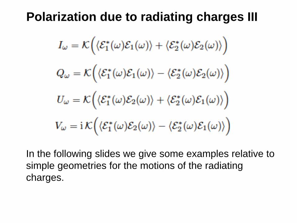
Polarization due to radiating charges III
In the following slides we give some examples relative to
simple geometries for the motions of the radiating
charges.
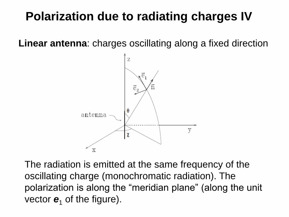
Polarization due to radiating charges IV
Linear antenna: charges oscillating along a fixed direction
The radiation is emitted at the same frequency of the
oscillating charge (monochromatic radiation). The
polarization is along the “meridian plane” (along the unit
vector e1 of the figure).

Polarization due to radiating charges V
Circular and elliptical antenna: the polarization of the
radiation emitted by the antenna matches the motion of the
oscillating charge.

Polarization due to radiating charges VI
Thomson scattering of radiation on free electrons
The components of the electric field of the scattered
radiation, E1 and E2, are connected to those of the incident
radiation, E1’ and E2’, by the equation

Polarization due to radiating charges VII
Translated into the Stokes parameters formalism the
previous eqaution results
Where the 4x4 matrix R (the Rayleigh matrix) is
with
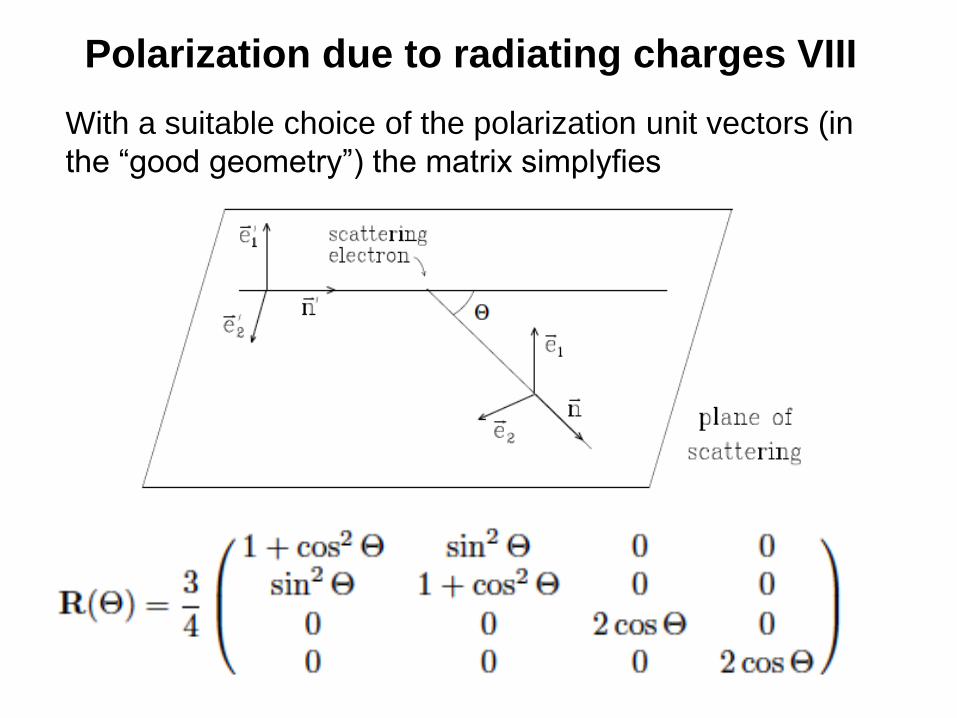
Polarization due to radiating charges VIII
With a suitable choice of the polarization unit vectors (in
the “good geometry”) the matrix simplyfies

Polarization due to radiating charges IX
In particular, for a scatering angle of 90º, the scattered
radiation is linearly polarized independently of the
polarization of the incident radiation. This behavior can be
easily understood in terms of linear oscillators.
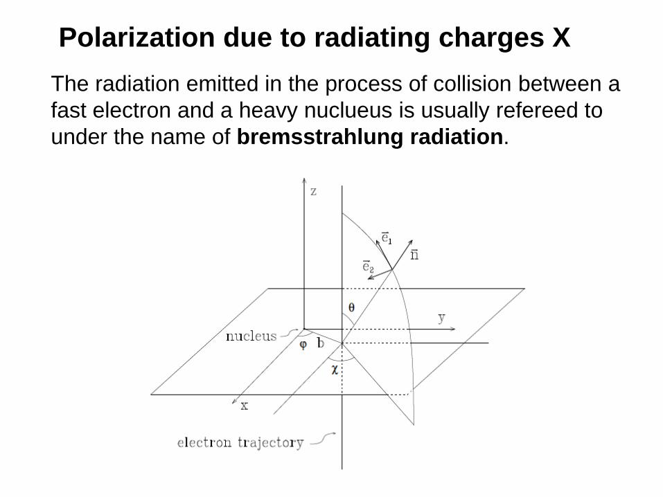
Polarization due to radiating charges X
The radiation emitted in the process of collision between a
fast electron and a heavy nuclueus is usually refereed to
under the name of bremsstrahlung radiation.
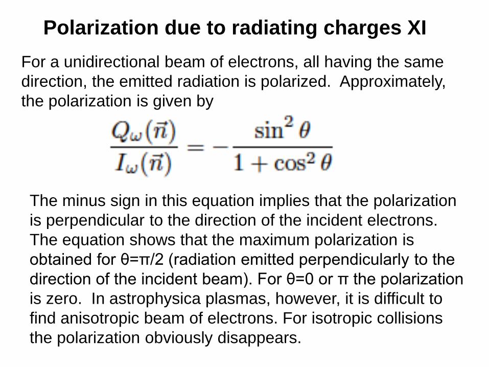
Polarization due to radiating charges XI
For a unidirectional beam of electrons, all having the same
direction, the emitted radiation is polarized. Approximately,
the polarization is given by
The minus sign in this equation implies that the polarization
is perpendicular to the direction of the incident electrons.
The equation shows that the maximum polarization is
obtained for θ=π/2 (radiation emitted perpendicularly to the
direction of the incident beam). For θ=0 or π the polarization
is zero. In astrophysica plasmas, however, it is difficult to
find anisotropic beam of electrons. For isotropic collisions
the polarization obviously disappears.

Polarization due to radiating charges XII
A non-relativistic electron moving under the action of a
constant and uniform magnetic field describes a helical
motion whose projection on the plane perpendicular to the
magnetic field direction is a circle. This circular motion has a
typical frequency called the cyclotron frequency
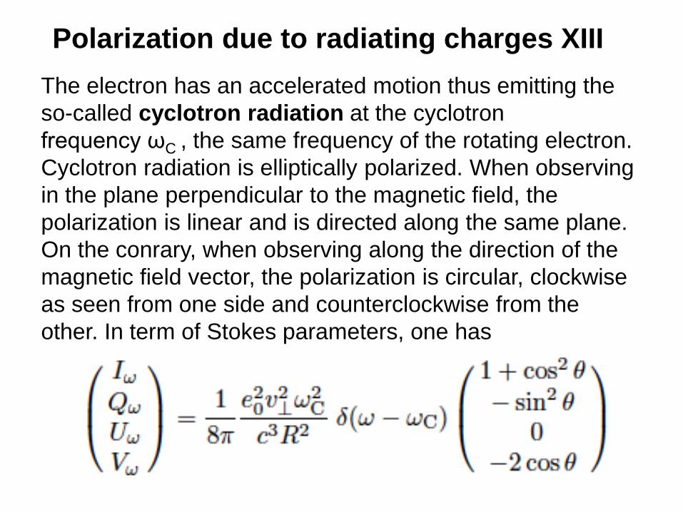
Polarization due to radiating charges XIII
The electron has an accelerated motion thus emitting the
so-called cyclotron radiation at the cyclotron
frequency ωC , the same frequency of the rotating electron.
Cyclotron radiation is elliptically polarized. When observing
in the plane perpendicular to the magnetic field, the
polarization is linear and is directed along the same plane.
On the conrary, when observing along the direction of the
magnetic field vector, the polarization is circular, clockwise
as seen from one side and counterclockwise from the
other. In term of Stokes parameters, one has

Polarization in spectral lines I
In the spectropolarimetric analysis of laboratory plasmas
and astrophysical objects, it is commonly observed that
spectral lines are polarized, the polarization signature
being, in general, different from line to line and variable
along the line profile. Line polarization may be
accompanied, or not, by continuum polarization. As typical
examples of astrophysical plasmas, we can just mention
sunspots and solar active regions, the higher layers of the
solar atmosphere (including the chromosphere and the
corona), magnetic stars, stars with extended envelops,
broad line regions of active galactic nuclei, astrophysical
masers, etc. The physical mechanisms involved are
different from object to object, but today it is possible to
treat the general phenomenon of generation and transfer of
polarized radiation within a uinque theoretical framework.

Polarization in spectral lines II
For describing the way an atom can produce polarized
radiation it is necessary to resort to a quantum description.
The simplest atomic model that can be considered is the
one of a two-level atom having angular momentum J=0 in
its lower level and angular momentum J=1 in its upper level.
The upper level is degenerate and is indeed composed of
three sublevels, characterized by a further quantum number
M that can assume the values 1, 0, and -1.

Polarization in spectral lines III
The three transitions correspond to different values of ΔM
and each of them is characterized by a particular antenna
diagram and a particular polarization of the emitted
radiation. Transitions having ΔM=0 behave, in emission as
linear antennas, while transitions having ΔM=1 or ΔM=-1
behave as circular antennas of different handedness. For
instance, looking along the direction of the quantization
axis, the ΔM=0 transition does not contribute to the
emission (the antenna is seen pole-on) whereas the other
two transitions emit radiation that is circularly polarized
(positive circular polarization for the ΔM=1 transition and
negative circular polarization for the ΔM=-1transition.) If the
levels are not split by a magnetic field (or by another
physical agent) and if the magnetic sublevels are evenly
populated the polarization washes out. Otherwise…

Polarization in spectral lines IV
A) The levels are split but evenly populated
B) The levels are degenerate but unevenly populated
In case A) there is circular polarization of one sign on a wing
of the line and circular polarization of the opposite sign in the
other wing. In the second case there is a net amount of
polarization across the whole line.

Polarization in spectral lines V
Iin case A) the polarization is due to splitting. This is the
“classical” case of the Zeeman effect. In case B), on the
contrary, we have a different phenomenon that is called
Atomic Polarization
The simplest manifestation of atomic polarization is the one
that we have just seen in the former example. The
degenerate sublevels of a given J-level can be unevenly
populated and this results in the emission of poalrized
radiation. But how can this phenomenon be generated?
How can an atom result in having its degenerate sublevels
unevenly populated? A possibility is the one of irradiating it
with anisotropic radiation. This possibility is referred to, in
laboratory physics, with the name of optical pumping.

Polarization in spectral lines VI
If the atom is illuminated by an unpolarized, unidirectional
radiation beam, then, assuming the quantization direction
along the incident beam, only transitions having either ΔM=1
or ΔM=-1 are efficient in populating the upper levels. This
results in a considerable amount of atomic polarization, as
here exemplified in the case of a 0-1 transition.

Polarization in spectral lines VII
For more "exotic" transitions the situation comes out to be
more complicated....
To treat the phenomena of atomic polarization it is necessary
to resort to a deeper description of the excitation of an atom
which goes beyond the simple one of the "unpolarized case"
where only the populations of the leves are specified. In
general, one has to specify the populations of the single
sublevels and, also, their phase relationships (coherence).

Polarization in spectral lines VIII
The most suitable theoretical tool to deal with these
phenomena of atomic polarization is the density-matrix
operator, defined in quantum mechanics by the equation
where pα is the probability of finding the atomic system in
the pure state α and where ⎮ψ(α) > is the corresponding
wave-function in Dirac's notations. The diagonal matrix
elements of the density-matrix operator
represent the populations of the single sublevels, whereas
the non-diagonal elements with M ≠ M'
represent the coherence.

Polarization in spectral lines IX
The density-matrix operator was introduced in the
astrophysical literature by M. Litvak in connection with his
studies of polarization in astrophysical masers. The first
application in solar physics is found in the thesis of
Véronique Bommier's, devoted to the study of polarization
in the D3 line of helium in prominences. Since then
it has become a common tool for
all the scientists working on the
subject of resonance scattering in
the solar atmosphere, with
particular emphasis on the so-
called second solar spectrum (the
spctro-polarimetric spectrum of the
Sun observed close to the limb).

Polarization in spectral lines X
The phenomena connected with atomic polarization are very
important in the physics of resonant scattering. This is also
because atomic polarization is sensitive to the presence of a
magnetic field. This physical phenomenon was discovered by
the german physicist W. Hanle around 1920, and now bears
his name. In modern terms, we can state that the Hanle
effect consists in the relaxation of atomic coherence due to
the presence of a magnetic field.

Polarization in spectral lines X
Due to the Hanle effect, when a scattering process takes
place in a magnetic environment, the scattered polarization
results in being modified from its "magnetic-field-free" value.
This allows to use the Hanle effect as a diagnostic tool for
measuring magnetic fields.
You will surely hear much more about the Hanle effect in this
Symposium. If you want to know more....