the prediction of passenger riding comfort from...
TRANSCRIPT

THE PREDICTION OF PASSENGER RIDING COMFORT FROM ACCELERATION DATA
CRAIG C. SMITH DAVID Y. McGEHEE ANTHONY J. HEALEY
RESEARCH REPORT 16
(\
MARCH 1976
~ " t0~:~f\ DEPARTMENT OF TRANSPORTATION ~;!!f!;J OFFICE OF UNIVERSITY RESEARCH \,Y; WASHINGTON, D. C. 20590
"'''IrES Of
~~(\(El) r~ Q:.'Q J9.1) ~ ":4 0' 0 '4 ~
:::D :::f
~ /TUDIE/
THE UOIVERIITY Of TEXA/ AT AU/Tin

RESEARCH REPORTS PUBLISHED BY THE COUNCIL FOR ADVANCED TRANSPORTATION STUDIES
1 An Integrated Methodology for Estimating Demand for Essential Services with an Application to Hospital Care. Ronald Briggs, Wayne T. Enders, James Fitzsimmons, and Paul Jensen, April 1974 (DOT-TST-75-81). 2 Transportation Impact Studies: A Review with Emphasis on Rural Areas. Lidvard Skorpa, Richard Dodge, C. Michael Walton, and
John Huddleston, October 1974 (DOT-TST-75-59). 4 Inventory of Freight Transportation in the Southwest/Part I: Major Users of Transportation in the Dallas-Fort Worth Area.
Eugene Robinson, December 1973 (DOT -TST -75-29). 5 Inventory of Freight Transportation in the Southwest/Part II: Motor Common Carrier Service in the Dallas-Fort Worth Area. J.
Bryan Adair and James S. Wilson, December 1973 (DOT-TST-75-30). 6 Inventory of Freight Transportation in the Southwest/Part III: Air Freight Service in the ballas-Fort Worth Area. J. Bryan Adair,
June 1974 (DOT-TST-75-31). 7 Political Decision Processes, Transportation Investment and Changes in Urban Land Use: A Selective Bibliography with Par
ticular Reference to Airports and Highways. William D. Chipman, Harry P. Wolfe, and Pat Burnett, March 1974 (DOT-TST-75-28). 9 Dissemination of Information to Increase Use of Austin Mass Transit: A Preliminary Study. Gene Burd, October 1973.
10 The University of Texas at Austin: A Campus Transportation Survey. Sandra Rosenbloom, Jane Sentilles Greig, and lawrence Sullivan Ross, August 1973. 11 Carpool and Bus Matching Programs for The University of Texas at Austin. Sandra Rosenbloom and Nancy Shelton Bauer, September 1974. 12 A Pavement Design and Management System for Forest Service Roads: A Conceptual Study. W. R. Hudson and Thomas G. McGarragh, July 1974. 13 Measurement of Roadway Roughness and Motion Spectra for the Automobile Highway System. Randall Bolding, Anthony Healey, and Ronald Stearman, December 1974. 14 Dynamic Modeling for Automobile Acceleration Response and Ride Quality Over Rough Roadways. Anthony Healey, Craig C. Smith, Ronald Stearman, and Edward Nathman, December'1974. 15 Survey of Ground Transportation Patterns at the Dallas-Fort Worth Regional Airport. William J. Dunlay, Jr., Thomas G. Caffery, Lyndon Henry, and Douglas Wiersig, August 1975. 16 The Prediction of Passenger Riding Comfort from Acceleration Data. Craig C. Smith, David Y. McGehee, and Anthony J. Healey, March 1976. 17 The Transportation Problems of the Mentally Retarded. Shane Davies and John W. Carley, December 1974. 18 Transportation-Related Constructs of Activity Spaces of Small Town Residents. Pat Burnett, John Betak, David Chang, Wayne Enders, and Jose Montemayor, December 1974 (DOT-TST-75-135). 19 Marketing of Public Transportation: Method and Application. Mark I. Alpert and Shane Davies, January 1975. 20 The Problems of Implementing a 911 Emergency Telephone Number System in a Rural Region. Ronald T. Matthews, February 1975. 23 Forecast of Truckload Freight of Class I Motor Carriers of Property. Mary Lee Gorse, March 1975 (DOT-TST-75-138). 24 Forecast of Revenue Freight Carried by Rail in Texas to 1990. David l. Williams, April 1975 (DOT-TST-75-139). 28 Pupil Transportation in Texas. Ronald Briggs, Kelly Hamby, and David Venhuizen, July 1975. 30 Passenger Response to Random Vibration in Transportation Vehicles. Anthony J. Healey, June 1975. 35 Perceived Environmental Utility under Alternative Transportation Systems: A Framework for Analysis. Pat Burnett, March 1976. 36 Monitoring the Effects of the Dallas/Fort Worth Regional Airport. Volume I: Ground Transportation Impacts. William J. Dunlay, Jr., Thomas G. Caffery, lyndon Henry, Douglas W. Wiersig, and Waldo Zambrano, December 1976. 37 Monitoring the Effects of the Dallas/Fort Worth Regional Airport. Volume II: [and Use and Travel Behavior. Pat Burnett, David Chang, Carl Gregory, Arthur Friedman, Jose Montemayor. and Donna Prestwood, July 1976. 38 Transportation and Community Development-A Manual for Small Communities: Level I, Volume I-Executive Summary; Volume II-The Planning Process. Richard Dodge, John Betak, C. Michael Walton, Charles Heimsath, and John Huddleston, July 1976. 39 An Evaluation of Promotional Tactics and Utility Measurement Methods for Public Transportation Systems. Mark Alpert, linda Golden, John Betak, James Story, and C. Shane Davies, March 1977. 40 A Survey of Longitudinal Acceleration Comfort Studies in Ground Transportation Vehicles. l. l. Hoberock, July 1976. 41 Lateral Steering Dynamics Model for the Dallas/fort Worth AIRTRANS. Craig C. Smith, December 1976 (Draft Report). 42 Guideway Sidewall Roughness and Guidewheel Spring Compressions of the Dallas/fort Worth AIRTRANS. William R. Murray and Craig C. Smith, August 1976 (Draft Report). 43 A Pavement Design and Management System for forest Service Roads: A Working Model. Freddy l. Roberts, B. Frank McCullough, Hugh J. Williamson, William R. Wallin, February 1977. 44 A Tandem-Queue Algorithm for Evaluation of Overall Airport Capacity. Chang-Ho Park, April 1977 (Draft Report). 45 Characteristics of Local Passenger Transportation in Texas. Ronald Briggs, January 1977 (Draft Report).

THE PREDICTION OF PASSENGER RIDING COMFORT FROM ACCELERATION DATA
Craig C. Smith David Y. McGehee
Anthony J. Healey
March 1976 RESEARCH REPORT
Document is available to the public through the National Technical Information Service,
Springfield, Virginia 22151
Prepa red for
COUNCIL FOR ADVANCED TRANSPORTATION STUDIES THE UNIVERSITY OF TEXAS AT AUSTIN
AUSTIN, TEXAS 78712
In cooperation with
U. S. DEPARTMENT OF TRANSPORTATION OFFICE OF UNIVERSITY RESEARCH
WASHINGTON, D. C. 20590
NOTICE
This document is disseminated under the sponsorship of the Department of Transportation, Office of University Research, in the interest of information exchange. The United States Government and The University of Texas at Austin assume no liability for its contents or use thereof.

1 ........... :I. .... .t Ace ... i_ No. l. Reci .. ;.,.t' .. C ....... No.
•• Title ... _"'itl. S. I.,.... D •••
The Prediction of Passenger Riding t;lomfort March, 1976
From Acceleration Data 6. P.d ....... O,_izot'_ c ....
7. _"-'S) a. P .. to-i ... 0 ..... "' __ R ...... t N ••
Smith, C. C., McGehee, D.Y., Healey, A. J. RR 16 t ........... 0 ... ",, __ ~ .. " AoIcIno •• 10. w .... U .. it No. (TRAIS)
Council for Advanced Transportation Studies 00 3655 8 The Uni versity of Texas at Austin u. D~r·OS 30093 Austin, Texas 78712
13. T,....I R ...... on" P .. iod Co.o,od
12. ... ...... a.-cy ~ ... ,.....,. ••
u. S. Department of Transportation Research Report Office of University Research Washington, D. C. 20590 1.. ..... ..... i ... AlOne" Codo
15. Suppl_tory No ...
1'6. A •• t'lICt
Various methods for evaluating ride quality in automobiles are investiga-ted by means of a field study involving two different automobiles, seventy eight different passengers, and eighteen different roadway sections. Passen-ger rating panels were used to obtain subjective evaluation of the various rides, and measured vibration spectra were compared on the basis of various evaluation techniques to determine their ability to predict the subjective ratings. Included in the evaluation criteria considered are the ISO (Inter-national Standards Organization) Standard, the UTACV (Urban Tracked Air Cushion Vehicle) Specification, and the Absorbed Power method of Lee and Pradko.
Excellent correlation was found to exist between the subjective ride ratings and simple root mean square acceleration measurements at either the vehicle floorboard or passenger/seat interface. Equations were develop-ed to predict the subjective ride rating from measured vibration spectra.
17. IC.., ... la. 01 .......... St. __
Ride Quality, Vehicle Vibrations, Document is available through the Passenger Comfort, Ride Rating National Technical Information Service
Springfield, Virginia 22151
1.. s-...tty CI ..... {of tit, ....... , •• "-tty CI ...... (of ......... ' 21 ...... IP .... 22. Prico
Unclassified Unclassified 103

EXECUTIVE SUMMARY
Abstract
Various methods for evaluating ride quality in automobiles are investigated
by means of a field study involving two different automobiles, seventy-eight dif
ferent passengers, and eighteen different roadway sections. Passenger rating panels
were used to obtain subjective evaluation of the various rides, and measured vi
bration spectra were compared on the basis of various evaluation techniques to
determine their ability to predict the subjective ratings. Included in the evalu
ation criteria considered are the ISO (International Standards Organization)
Standard, the UTACV (Urban Tracked Air Cushion Vehicle) Specification, and the
Absorbed Power method of Lee and Pradko.
Excellent correlation was found to exist between the subjective ride ratings
and simple root mean square acceleration measurements at either the vehicle floor
board or the passenger/seat interface. Equations were developed to predict the
subjective ride rating from measured vibration spectra.
Introduction
The acceptance of any new transportation system is affected by the vibrations
or "ride quality" to which passengers are exposed. Study of the response of pas
sengers to a vehicle vibration environment has therefore become increasingly im
portant to assist in the development of these new systems. While underdesign
of a system with regard to allowed vibration levels can cause it to be unacceptable
to the traveling public, overdesign can lead to excessive system costs.
It is therefore imperative that we understand the relationships between
allowed vibration levels and passenger acceptance. This study is a detailed study
of these relationships for the automobile, a presently well accepted mode of trans
portation within the common experience of the traveling public. This provides a
baseline comparison for examination of other, newer modes of transportation.

Method
The collection of data for the study here described included the measurement
of passenger subjective response (ratings) to a variety of riding vibrations in
different automobiles over different roadways. Acceleration measurements of the
corresponding vibrations were also recorded, including both vertical and lateral
floorboard and vertical and lateral seat/passenger interface accelerations. The
subjective (passenger ratings) and objective (acceleration measurements) measures
of the ride were then compared via a variety of proposed ride rating methods to
determine the method which best predicts the subjective ratings using the objective
measurements. Methods compared include the ISO Standard, the UTACV Specification,
the Absorbed Power method of Lee and Pradko, and frequency weighting techniques
utilizing various proposed curves relating human sensitivity to vibration as a
function of frequency.
Findings and Results
A variety of the frequency weighting schemes investigated relate reasonably
well to the subjective passenger responses. Of these, the simple r.m.s. accelera
tion measures, the simplest to use, are also consistently as good of predictors
as the more elaborate schemes. Measured at the floorboard, the vertical r.m.S.
acceleration is an excellent predictor. while at the nassenger/seat interface, the
lateral r.m.s. acceleration is the better predictor. The magnitude (defined as the
square root of the sum of the squares of the vertical and lateral r.m.s. values)
acceleration is a good predictor for either the floorboard or passenger/seat inter
face vibrations.

ACKNOWLEDGEI~ENT
This work was supported by the U. S. Department of Transportation, University
Research Offi ce, under contract DOT -OS- 30093, admi ni stered through The Council for
Advanced Transportation Studies at The University of Texas at Austin.
Also of significant help to the project was the loan of a portable three
axis accelerometer package by the Nasa-Langley Research Center and the support of
the Texas State Department of Highways and Public Transportation and The University of
Texas Center for Highway Research in identifying the highway test sections used.

TABLE OF CONTENTS
NOMENCLATURE
INTRODUCTION
1.1 Existing Criteria
1.2 Objectives and Scope of Study
MEASUREMENT AND PROCESSING OF ACCELERATION DATA
2.1 Measurement of Accleration Data
2.2 Digitizing of Data
2.3 Spectral Density Calculations
2.4 Weighted RMS Acceleration "ride index" Calculations
PSYCHOMETRIC EXPERIf'lIENTS FOR RI DE EVALUATION
3. 1 Bui ck Rating Sessions
3. 1 . 1 General
3.1.2 Routes
3.1.3 Design
3. 1 .4 Subjects
3.1.5 Procedure
3.1.6 Res u1 ts
3.2 Maverick Rating Session (Fa 11 1975 )
3.2. 1 General
3.2.2 Design
3.2.3 Sensory Modes
3.2.4 Subjects
3.2.5 Procedure
3.2.6 Results
2
4
6
6
8
10
10
12
12
12
12
13
13
13
14
14
14
14
15
15
15
16

COMPARISON OF PASSENGER RATINGS WITH ISO AND UTACV SPECIFICATIONS 17
4.1 Comparison with UTACV Boundaries
4.2 Comparison with ISO Boundaries
FREQUENCY WEIGHTED RIDE INDICES AND THEIR CORRELATION WITH MEAN PERSONAL RATINGS
5.1 Weighting Functions
5.2 Absorbed Power
5.3 Unweighted RMS Acceleration Ride Indices
5.4 Correlation Study
5.5 Discussion of Statistical Results
5.5.1 Frequency Weighting Versus Unweighted Values
5.5.2 Significance of Location of Measurement and Direction of Vibration
5.5.3 Seat Versus Floorboard Measurements
5.5.4 Significance of Frequency Range Considered
5.6 Summary
RI DE EVALUATION EQUATIONS
6.1 Proposed Comfort Equation
6.2 Discomfort Equation
CONCLUSIONS AND RECOfv1MENDATIONS
REFERENCES
APPENDIX A
A.l Introduction
A.2 Detrendi ng
A.3 Power Spectrum Calculations
A.4 Data Averaging
APPENDIX B
Subjective Rating Form
17
20
22
22
28
31
31
32
32
38
39
39
40
41
41
42
45
47
48
48
49
50
50
51
51

APPENDIX C
Spectral Density Plots
APPENDIX 0
Weighted Indices
APPENDIX E
E.1 Scattergrams
E.2 Correlation Coefficients and Ride Index Equation Parameters for Various Weighting Functions
52
82
87
100

LI ST OF FI GURES
Figure 2.1: NASA Accelerometer Package
Figure 2.2: Endevco Accelerometer Package, Signal Conditioner and Power Supply
Figure 2.3: TEAC R200 DR/FM Data Recorder
Fi gure 5. 1: Frequency Wei ghti ng Functi ons
Figure 5.2: Absorbed Power ~/eighting Values
Figure 5.3: Correlation of Weighted Indices for Maverick
Page
7
7
9
27
29
Seat Vibrations with Mean Personal Ratings 34
Figure 5.4: Correlation of Weighted Indices for Maverick Floor Vibrations with Mean Personal Ratings 35
Figure 5.5: Correlation of Weighted Indices for Buick Floor Vibrations with Mean Personal Ratings 36
Figure 5.6: Correlation of Weighted Indices for Combined Buick and Maverick Floorboard Vibrations with Mean Personal Ratings 37
Figure 6.1: Least Squares Curve Fit to Magnitude RMS Accelerations Within the 0 to 40 Hertz Band vs. Mean Personal Ratings 43
LI ST 0 F TABLES
Table 4.1: UTACV Graphical Analysis
Table 4.2: ISO Graphical Analysis
Table 5.1: Frequency Weighting Functions (frequency in hertz)
Table 5.2: Absorbed Power Weighting Functions
Table 5.3: Correlation Coefficients
Page
18
19
25
30
33

NOMENCLATURE
A(f) = amplitude of constant comfort or vibration limit boundary
AP = absorbed power
D = discomfort index = 5.0-R
f circular frequency (cycles/sec.)
fm = maximum frequency of interest
MPR = mean personal rating of passengers for a given ride
P(f) = power spectral density
R
RMS40
RMS100
w( f)
x(t)
z a.
ride number (predicted MPR)
= root mean square acceleration in 0 to 40 hertz band
root mean square acceleration is 0 to 100 hertz band
= weighting function
= acceleration
impedance
root mean square acceleration
02 = residual variance of R from least squares fit of MPR as a linear
function of a.
o standard deviation
Subscript
w = weighted value

1. INTRODUCTION
In transportation vehicles, an important part of the passenger's environ
ment is the vibration to which he is subjected. Information concerning the re
sponse of passengers to a vehtcle vibration environment has become increasingly
important for use in the development of new transportation systems. While under
design of a new system with regard to allowed vibration levels can cause it to be
uncomfortable and hence unacceptable to the traveling public, overdesign (where
vibrations that would normally not affect the passenger's perception of
comfort significantly are eliminated) can result in excessive system cost.
Indeed, in many cases system cost is very strongly related to the ride quality
criteria that may be imposed upon the designer. This study is an attempt to
relate passengers' perceptions to measured riding vibrations in order to evalu
ate some design criteria presently in use and to develop better criteria for
vehicle ride comfort design.
The automobile was chosen as the vehicle upon which to base this study
for a variety of reasons. Firstly, it represents a riding environment with
which most people are familiar. This tends to make it a common basis upon
which to begin when rating ride quality, and will allow extrapolation to new
environments based upon experience common to the majority of passengers.
Secondly, the automobile is relatively convenient for use in this type of
field study. It is relatively easy to control the general passenger environ
ment, the roughness of the roadway, etc. Thirdly, previous work at The Uni
versity of Texas Center for Highway Research,where similar types of field
studies have been used to evaluate pavement "serviceability" or roughness
[l]~ provides useful background information and experience for this type of
study.
*Numbers in [ ] refer to references in Bibliography.
1

1.1 Existing Criteria
A number of ride quality "criteria" are presently in existence. Notable
among these are the I nternationa 1 Standards Organi zati on (ISO) II A Gui de to the
Evaluation of Human Exposure to Whole Body Vibration" [2], Lee and Pradko's
"Absorbed Power ll [3), The Urban Tracked Air Cushion Vehicle (UTACV) Specification
[4), and acceleration limits as a function of frequency given by Janeway [5] and
Dieckmann [6]. A review of the literature discussing the origin of these criteria
as well as other work in the area is included in [7]. In general, the limits of
Janeway and Dieckmann are rms acceleration limits for pure sinusoidal vibrations.
The concept proposed is that if the rms amplitude of each sinusoidal component
contained within the ride does not exceed the proposed limits, the ride should
be comfortable. The difficulties with using these criteria are twofold. Firstly,
riding vibrations are never pure sinusoids and even though basic components can
be isolated by bandpass filtering the amplitude is strongly dependent upon the
filter characteristics. As one manufacturer put it, Hall we had to do was to
reduce the bandwidth until we met the criteria. II The second problem associated
with this type of criteria is that it assumes no interaction between components
of different frequencies. That is to say it is not intuitively satisfying to
assume that a ride with two basic v'ibration components at different frequencies,
both of which are just below the limits, is a better ride than another with only
one vibration component which is a little above the limit. (Note that in the
latter case the total rms vibration level could far exceed the first case.)
The ISO Standard is of essentially the same form as the limits of Janeway
and Dieckmann, except it specifies the bandwidth over which the rms at any given
II cen ter frequencl' should be calculated as one-third octave. This helps some
what, but the difficulty of differentiating between mult'iple component vibrations
rema; ns.
2

The UTACV Specification is a boundary below which the power spectral density
(PSD) of the ride accelerations must be at all frequencies. This specification
also avoids the bandwidth problem (if care is used in calculation of the PSD),
but again retains the problem of multiple components or regions where the PSO
just meets the specification vs. one component which exceeds only at one point
with all other points well below the boundary.
The II absorbed power" concept of Lee and Pradko di ffers somewhat in approach
from the other criteria discussed in that it relates the quality of the ride to
a single number, i.e. the average power absorbed by the passenger due to the
riding vibrations during the ride. The average absorbed power is computed as a
weighted integral of the acceleration spectral density, where the weighting func
tion is the squared magnitude of the mechanical impedance of the human at the
boundary between the human and the medium imposing the motion where the accel
eration is measured. Lee and Pradko define impedances for various body loca
tions for an lIaverage manll. This concept is somewhat appealing from a designer's
point of view since it reduces all ride variables to a single scaler number which
is urepresentative" of the ride quality. The primary difficulty here is that the
criterion has not been suitably verified in a realistic ride environment.
Closely related to the approach of Lee and Pradko is the approach proposed
by Butkunas [8], using a weighted rms acceleration as a one-number ride index.
Butkunas indicates that anyone of the proposed comfort limits (such as those
mentioned above) represents human sensitivity to vibration, and as such, can be
used to develop weighting functions or IItransfer functions". One difference
between this approach and that of Lee and Pradko is that the weighting function
is defined by a generalized transfer function representing human perception of
ride, whether that perception relates to the mechanical impedance or not, where
as the absorbed power method uses only the mechanical impedance as a weighting
3

function. Another difference lies in the fact that even when the mechanical
impedance is the weighting function for both approaches, the weighted rms
acceleration is proportional to the square root of the absorbed power rather
than proportional to the absorbed power. Thus the two approaches assume a
different functional relationship between amplitude of ride vibrations and
human sensitivity.
1.2 Objectives and Scope of Study
The objective of this study is to examine each of the ride quality evalua
tion methods presented above on the basis of a field experiment. The field ex
periment used two different automobiles (a 1974 Buick Century Luxus and a 1975
Ford Maverick), 78 different passengers, and 18 different roadway sections.
Both objecti ve measurements of the ri di ng vi brations and subjecti ve measures
of the passengers' perceptions of each ride were taken.
A preliminary examination of the data consists of a study of the ability
of the UTACV Specification and the ISO Standard to indicate or predict the
passengers' perceptions. The larger, remaining part of the study examines the
use of each of the above boundary type criteria (ISO, lITACV, Janeway, Dieckmann)
as frequency weighting functions to calculate frequency weighted rms accelera-
tion ride indices as proposed by Butk!:lnas. In addition, absorbed power ride
indices are also calculated. The coefficient of correlation between the ride
indices and the mean personal (subjective) ratings of the passengers in each
case is then examined. Relative effects of each weighting function or method
are compared.
The measurement of riding vibrations, signal processing, filtering, and
spectral density calculations are described in Chapter 2. In Chapter 3 the
psychometric experiment used to measure the passenger's "mean personal rating"
4

or subjective evaluation of the ride is discussed. The ISO Standard and the UTACV
Specification are examined in detail relative to the experimental data in Chapter
4. In Chapter 5, the various frequency weighting functions are described and
compared on the basis of their ability to produce a weighted value which correlates
with the mean personal (subjective) ratings of the passengers. In Chapter 6, a
ride quality criterion is presented based upon the results of Chapter 5. Con
clusions and recommendations are summarized in Chapter 7.
5

2. MEASUREMENT AND PROCESSING OF ACCELERATION DATA
2.1 Measurement on Data
The acceleration data used in this experiment included vertical and lateral
accelerations on the floorboard of a 1974 Buick Century Luxus and a 1975 Ford
Maverick, and vertical and lateral accelerations of a 12 inch circular disk of
1/4 inch plywood placed between the seat and a 155 lb. passenger who was sitting
on the disk. The accelerations were measured while the vehicles were driven at
50 mph, approximately 2 foot left of center of the road, over highway test sections
designated by the Texas State Department of Highways and Public Transportation.
These sections are approximately 1250 ft. long and contain approximately sta
tionary prof-iles (no curves or significant grades) throughout each individual
test section. Each section has been given a serviceab-ility index (S.I.) by the
Texas State Department of Highways and Public Transportation which is an indi
cation of its roughness on a six point scale (0 = very rough, 5 = very smooth).
The sections used ranged in S.I. ratings from 1.9 to 4.3, including a varity of
roughnesses from some fairly rough farm to market road sections to very smooth
interstate highway.
To measure the accelerations on the floorboards, a three axis accelerometer
package loaned to The University of Texas by the NASA Langley Research Center
(Figure 2.1) was used. The package is self-contained, including its own
batteries and signal conditioning equipment. The frequency response of the
accelerometer package supplied by NASA is about 3db. down at 100 hertz, effec
tively low pass filtering the data measured by it. The metal box containing the
accelerometer package has 3 metal Ilspike ll feet which penetrate the carpet and
contact the metal floor pan. To avoid bouncing of the package on the floorboard
(should it otherwise occur), the package was lodged securely under the rear of
the front seat on the passenger (right) side of the car.
6

Figure 2.1. NASA Accelerometer Package
Figure 2.2. Endevco Accelerometer Package, Signal Conditioner and Power Supply
7
The seat accelerations were measured using a smaller accelerometer package
consisting of a triaxial arrangement of Endevco model 2265-20
accelerometers, an Endevco model 7441 signal conditioning module, and an
appropriate power supply (Figure 2.2). The small triaxial accelerometer package
was mounted on a 12-inch-diameter circular disc of 1/4-inch plywood. The disc
was placed underneath the passenger on the front passenger seat.
For each test section and car combination, vertical: and lateral acceleration
signals were recorded on the first two channels of a TEAC R200 DR/FM Data Recorder
(see Figure 2.3) while verbal commentary was recorded on the fourth channel.
Since for the Ford Maverick both seat and floorboard vibrations were measured,
two separate runs over each test section were required, one for the floorboard
and one for the seat. During the measurement process, the car contained 3
passengers (including the driver) and the tape recorder on the rear seat on the
right side of the car, making the load distribution somewhat similar to the load
distribution of 4 passengers (including the driver) during the subjective ride
evaluation tests described in the next chapter.
2.2 Digitizing of Data
After the acceleration measurements were recorded, the analog signals were
digitized for processing by digital computer. During the course of the experi
ment, two different facilities were used for the digitizing process. For the
Buick vibrations a Hewlett-Packard 2115 Computer with A/D converter which is
owned by the Texas State Department of Highways and Public Transportation was
used to sample and digitize the signals at a sampling rate of 434 samples per
second. The Maverick vibrations were digitized at the Hybrid Computer Labora
tory at The University of Texas. The sampling rate for this data was also 434
samples per second, and the samples were read into an SDS 930 computer. During
the digitizing of the Maverick data, a Hewlett-Packard 4509A low pass filter
8

I • - -" -. -• I · • • • I • I • · • • , · , , . • , • I ., . I.. • __ , -. _.
... "' .....
Figure 2.3. TEAC R200 DR/FM Data Recorder
9

with 100 hertz cutoff frequency was used ahead of the sampler to avoid aliasing
problems. For the previously digitized Buick Data this was not necessary be
cause the NASA - Langley accelerometer package itself has a frequency response
which rolls off at about 100 hertz. For both of these processes, the digi
tized data were written on magnetic tape (7 track) at 556 bpi. These magnetic
tapes were then read into The University of Texas CDC 6400/6600 digital compu-
ter for signal processing.
2.3 Spectral Density Calculations
All of the processing of the data described in this report requires calcu-
lation of the spectral density, or more commonly but less properly the "power
spectral density" (PSD) of each of the acceleration profiles. The spectral
density, defined as the Fourier transform of the autocorrelation function, ;s a
measure of the average squared magnitude of the signal content per unit bandwidth
as a function of frequency. Efficient calculation of the spectral density of a
finite data sequence such as the test section acceleration profiles described
herein is accomplished using the Fast Fourier Transform (FFT) algorithm. The
procedure for these calculations, including windowing and data averaging, is
described in detail in Appendix A.
2.4 Weighted RMS Acceleration IIRide Index" Calculations
From the power spectral density of a given signal, the mean square amplitude
of the signal can be calculated as the integral over all frequencies of the PSD, or
(2,1)
where x(t) is the signal as a function of time t, and P(f) is the PSD as a function
of circular frequency f. For a sampled signal, frequency content is limited to
the Nyquist folding frequency (one-half the sampling frequency), or our interest
10

may otherwise be limited to signal content below some given frequency f so we m
may write
(2.2)
where all components above f are either assumed to be neglig"ible or not to be m
of interest. The root mean square (rms) value is then the square root of x2(t)
or
(2.3)
Since it is reasonable to assume that passengers are more sensitive to acceleration
"power" at some frequencies than others, a weighted mean square acceleration level
can be defi ned as f m
~ =Io W(f) P(f)df (2.4)
where x represents the weighted mean square value and W(f) is a weighting w
function which reflects the desired weighting to reflect passenger sensitivity.
Actual weighting functions used in this study are described subsequently and
are based upon various constant comfort contours. Calculation of the weighted
mean square value ~ given the functions W(f) and P(f) as sampled data sequences,
is accomplished through numerical integration using Simpson's rule. The weighted
root mean square ride index is then calculated as simply the square root of ~:
Q_ =J~ = (fm W(f) P(f)df (2.5) W J o
The various weighting functions W(f) used and compared in this study are
described in detail in Chapter ,ll, along with the curves from which they were
obtained.
11

3. PSYCHOMETRIC EXPERIMENTS FOR RIDE EVALUATION
To determine the subjective rating of a variety of passengers in different
ri d; ng env; ronments, a two-part psychometr; c experiment was performed. The fi rst
part of the experiment, conducted during the spring of 1974 used a 1974 Buick
Century Luxus automobile as the test vehicle. After examination of the results
of the first part, the second part was done in December, 1974, using a 1975 Ford
Maverick as the test vehicle.
3.1 Buick Rating Sessions
3.1.1 General Each of 24 subjects was driven in the same 1974 Buick
Century Luxus over six road sections. Of these sections, two were rough,
two were medium, and two were smooth, based upon their SI as described below.
Many background variables were considered in order to reveal any biasing of
the subject due to his daily environment. Background variables such as per
sonality measures, age, and type of vehicle normally driven were included
in an attempt to relate these variables to the subject's rating ability.
3.1.2 Routes The total of eleven roadway test sections used in this
part of the experiment were divided into four routes. Each of these routes
contained one each of the rough, medium and smooth categories of road sections.
One test section (Section 5) was used on two routes. These road sections were
obtained from the Texas State Department of Highways and Public Transportation,
which measures and studies these sections periodically four times a year. Each
section is given a Serviceability Index (SI) value which is computed from
measurements of the road surface. These measurements are taken with a General
Motors Surface Dynamics Profilometer (for more information on profi10meter see
[9]), which measures the profile of the road in the wheel tracks of the vehicle.
The SI values may range from 0 to 5 (5 being smoothest and 0 being roughest);
however, the sections available for use on this experiment ranged from 2.3 to 4.3.
12

The sections were grouped according to their S.l. values as follows:
S. I.
rough (2.0 to 2.99) medium (3.0 to 3.99) smooth (4.0 to 5.0)
3.1.3 Design Each subject was driven over two routes and made six
ratings of ride quality. To avoid the possibility of bias in the ratings
of ride quality the driving sequence of sections within routes was varied
systematically. This was accomplished by reversing the order of sections within
routes (1,2,3 to 3,2, 1) and varying the rough, medium, and smooth order from
one route to another in order that approximately one~hird of the routes started
with smooth sections, another one third started with medium sections, and so on.
Simi1ari1y, the second and third sections were equally often smooth, medium, or
rough. This accounted for any variance in the rating ability of the subjects
which could have been affected by practice, boredom, or fatigue acquired during
the rating session.
3.1.4 Subjects Twenty-four subjects served in this experiment. Half of
these were driven over two of the routes and the other half over the other two
routes. Subjects were obtained from introductory psychology classes and served
in the experiment to fulfill a laboratory requirement.
3.1.5 Procedure Groups of three subjects were used in each session of the
experiment. The group was assembled at The University of Texas, where personality
tests and background questionnaires were completed. Next, they were seated in the
automobile, two in the back seat and one in the front seat, and driven to the
appropriate test sections. The same driver drove the car for all subjects. Care
was taken by the driver to maintain the same conditions throughout the rating
sessions, which included emphasizing the importance of the experiment. The sub
jects were driven over the test sections at 50 m.p.h. approximately 2 feet to the
13

right of the highway center stripe and then asked to evaluate the ride using the
rating questionnaires (See Appendix B). Ratings were defined to range from 1
C'the worst ride I can think of") to 5 (lithe best ride I can think of ").
3.1.6 Results The analysis of the data yielded several items of significance.
Individual ratings were found to have significant agreement with the Mean Per-
sonal Ratings (M.P.R.) as well as (5.1.) values previously mentioned. The
correlation between the S.l. values and M.P.R. values was .92. Also, it was
found that personality and background variables had little effect upon the sub
jects ' ratings. The main significance of these findings from the standpoint of
this study is the fact that the personal ratings of the ride are repeatable and
valid and can therefore be compared to the study of the measured vehicle vibrations.
3.2 Maverick Rating Session (Fall 1975)
3.2.1 General Each of 54 subjects was driven in a 1975 Ford Maverick over
nine sections. Of these sections, three were rough, three medium, and three
smooth. Unlike in the Buick study, all subjects rated all of the road sections;
however, driving order and controlled conditions varied according to the design
of the experiment. Due to the findings of the previous experiment, background
differences were not considered. Instead, subjects in different rating sessions
were exposed to different audio and visual stimuli during the runs over the sections.
3.2.2 Design Nine road sections were used in this study, with each road
section being rated by each of 54 passengers. The driving route was broken up
"into three groups, each of which contained a rough, medium, and smooth section
with regard to 5.1. values as in the previous study using the Buick. The order
of rough, medium, and smooth sections in each of the groups was different. In
addition, the driving sequence was varied by switching the order of the groups
systematically to avoid the possibility of bias in the ratings. Each subject
was driven over the nine sections of the route and made a rating of each section
immediately after riding over the section.
14

3.2.3 Sensory Modes While travelling over the road sections the subjects
were put in three different sensory modes to judge the road sections. These are
referred to as the "deleted", "added", and II con trol" modes in both audio and
visual senses. The "deleted" mode used a'blindfold for visual effect and ear-
plugs and headset for audio. For "added" stimuli, the subjects were asked to search
for letter targets on a sheet of paper for the visual mode and from a recorded
tape for the audio mode. The "control" mode required just sitting still. Audio
and visual modes were not mixed between the passengers in each group.
3.2.4 Subjects Fifty-four subjects served in this experiment and, as in the
prior study, they were obtained from introductory psychology classes and served
in the experiment to fulfill a laboratory requirement.
3.2.5 Procedure Groups of three subjects were used in each session of the
experiment. A group was assembled at The University of Texas, and instructions
for the respective tasks were given and forms were completed. Next, they were
seated in the automobile, two in the back seat and one in the front seat, and
driven to the appropriate starting point. For all subjects, a 1975 Ford Maverick
was used as the test vehicle and the driver was the same. Care was taken by the
driver to maintain the same conditions throughout the rating sessions, except
for the planned differences in the audio and visual inputs. Each group had two
audio or visual tasks to perform for six roadway sections and control conditions
for the other three sections. Prior to reaching a roadway section, the
subjects were allowed to prepare for the section as they had previously been
instructed. They were then driven over the test sections at 50 m.p.h., approxi
mately two feet right of the highway center stripe, and asked to evaluate
the ride using the questionnaires (See Appendix B). Within a given group all
subjects were in the same sensory mode at a given time. As in the previous
15

experiment, ratings were defined over the range from 1 (lithe worst ride I can
think of"), to 5 C'the best ride I can think of ").
3.2.6 Results The analysis of the data yielded several items of signifi
cance. The main point, however, was that Mean Personal Rating (MPR) again
had a relatively high correlation with the SI value ( = .87). This is slightly
lower than the previous test with the Buick ( = .92); however, this is under
standable since the SI equations were derived from a regressive fit of profile
data with data from similar rating sessions using a full-sized sedan similar to
the Buick. Since the Maverick was smaller, a less comfortable ride was possible
for certain sections.
16

4. COMPARISON OF PASSENGER RATINGS WITH ISO AND UTACV SPECIFICATIONS
The ISO Standard and the UTACV Specification describe boundaries which are
interpreted as defining the acceptability of given riding vibrations. It is
therefore instructive to examine by graphical analysis the vibration spectra of
the riding vibrations measured in this study to determine to what degree each of
these criteria relates to the mean personal subjective rating of the passengers
for each ri de.
4.1 Comparison with UTACV Boundaries
To compare each of the rides with the UTACV Specifications~ the spectral
density of the vertical and lateral vibrations measured at the floorboard of the
Buick and at the floorboard and seat of the Maverick were plotted against the
specification. The corresponding plots are shown in Appendix C. By inspection
of these plots each section was classified as rough (R), medium (111), or smooth
(S) with regard to each of its characteristic spectra (vertical, lateral, floor,
seat). A given spectrum was characterized as smooth if it was below the boundary
at all frequencies, medium if only small peaks were above the boundary, and rough
if large multiple peaks were above the boundary. Admittedly, a great deal of
subjectivity was required in these categorizations. The results of this graphical
analysis are presented in order of decreasing MPR (decreasing passenger comfort
rating) in Table 4.1.
As can be seen from Table 4.1, none of the sections was rated smooth with
regard to all spectra. In other words all the automobile rides measured had spectra
which exceeded the UTACV boundaries at some frequencies, indicating the boundary
may be somewhat too conservative in II/hat it allows. Also notable is the fact
that even though rides with lower MPR's tended to have "rougher" spectra, there is
some overlap. For instance, Buick section 3, with a MPR of 3.83, has R vertical
and M lateral spectra whereas Buick sections 1 and 8, both having a MPR of 3.50,
have M vertical and lateral spectra. Vertical and lateral spectra seem to be rated
17

Table 4.1 UTACV Graphical Analysis
Maverick (Seat and Floor)
Section Floor Seat MPR SI Vertical Latera 1 Vertical [ateral t
9. M M S M 4.09 4.2
10 M M S M 4.07 4.3
14 M M M M 3.85 3.4
36 M M S M 3.80 4.2
40 M R S R 3.39 3.5
15 R R M R 2.72 3.6
39 R R M R 2.67 1.9
35 R M M R 2.54 2.0
38 R R R R 2.20 2.0
S = smooth M = medium R = rough
Buick (Floor Only)
Section Vertical Transverse MPR SI =
5 M M 4.42 4.0 7 M M 4.25 4.3 9 M M 4.17 3.9 3 R M 3.83 3.4 1 M M 3.50 3.5 8 M M 3.50 3.4 6 R M 3.00 2.8
41 R M 3.00 2.6 2 R M 2.33 2.7
39 R R 2.33 2.3 37 R ~1 2.23 3.0
~.=:::.;,::;: ............. r=r - == =
18
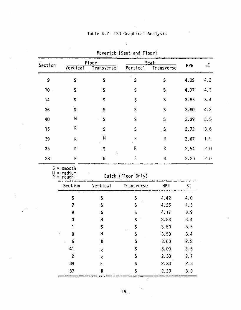
Table 4.2 ISO Graphical Analysis
Maverick (Seat and Floor) -Section Floor Seat MPR SI Vertical Transverse Vertical Transverse
9 S S S S 4.09 4.2
10 S S S S 4.07 4.3
14 S S S S 3.85 3.4
36 S S S S 3.80 4.2
40 M S S S 3.39 3.5
15 R S S S 2.72 3.6
39 R M R M 2.67 1.9
35 R S R R 2.54 2.0
38 R R R R 2.20 2.0
S = smooth ~1 = medi um Buick (Floor Only) R = rough
Section Vertical Transverse MPR SI
5 S S 4.42 4.0 7 S S 4.25 4.3 9 S S 4.17 3.9 3 M S 3.83 3.4 1 S S 3.50 3.5 8 M S 3.50 3.4
6 R S 3.00 2.8
41 R S 3.00 2.6 2 R S 2.33 2.7
39 R S 2.33 2.3 37 R S 2.23 3.0
==--=-~~ . .,....--- -..;:.==,...::.:.:=-=---== : .. .=-=:; .. " ... -~.:-.- -- --=--:.::=..::....--:-=
19

about equally in "roughness", indicating neither to be dominant in determining
the quality of the ride. All rides with MPR less than or equal to 3.39 had an
R rating of the spectrum for either the vertical or lateral directions or both.
4.2 Comparison With ISO Boundaries
An analysis similar to that above was also performed using the ISO Standard.
In this case the rms acceleration within each one-third octave band from 1 hertz
to 80 hertz was plotted versus the ISO 8 hour and 1 hour boundaries for each spectra
of interest. These plots are also found in Appendix C. Also plotted with the
power spectral density plots used in the UTACV analysis above are "equivalent"
ISO boundaries which represent the magnitude that the average value of the PSD within
the one-third octave band centered at a given frequency cannot exceed in order
for the RMS value within the band to be below the original ISO boundary. (For
development see [10].) As with the UTACV analysis, each spectrum was categorized
as smooth, medium, or rough. In this case, all categorizations were defined
relative to the 8 hour boundary, where smooth was the rms level with all bands
being below the boundary, medium was the rms level with only one band being on
or above the boundary, and rough was the rms level with multiple bands being
on or above the boundary. The results are shown in Table 4.2.
In this case, all spectra with mean personal ratings greater than or equal
to 3.85 were rated as smooth. All sections except sections 39 and 38 in the
Maverick were rated smooth with regard to floorboard lateral vibrations, which
would tend to indicate that either the vertical vibrations are more important
in determining the ride quality for these cases or the lateral boundary is less
restrictive than the vertical relative to a given ride comfort level. Again
there is some overlap between roughness ratings (for example, the vertical spectra
for section 3 in the Buick is rated M,with a MPR of 3.83,while section 1 is rated
20

S, with an MPR of 3.50), but there is a very definite trend for "rougher"
ratings with decreased MPR. All rides with a MPR of 3.00 or less were rated
R in at least one of the spectra measured on the floorboard, whereas only
rides with a MPR of 2.67 or less were so rated by spectra measured at the seat.
21

5. FREQUENCY WEIGHTED RIDE INDICES AND THEIR CORRELATION WITH MEAN PERSONAL RATINGS
5.1 Weighting Functions
Since the boundary-type criteria proposed by Janeway, Dieckmann, ISO, and
the UTACV specification represent in some sense human sensitivity to vibration
as a function of frequency, each can be used to develop a "transfer function"
relating human sensitivity to the riding vibrations. Stated in other terms,
each can be used to develop a weighting function which can be used to weight
the vibration spectra according to each criterion's definition of the sensi
tivity of man to vibrations at given frequencies.
If the "boundari' specifies, for instance, the maximum level which should not
be exceeded by the magnitude of a sinusoidal vibration, then one might wish to
use the value of the magnitude of the sinusoidal vibration divided by the value
of the boundary at the corresponding frequency as a ride ratio or index of the
ride by which various sinusoidal rides at different frequencies could be compared.
Carrying this a little further, rides consisting of multiple sinusoids could be
compared by adding the ride ratios for all of the individual components of the
ride to get an overall ride index. In the limit,for the spectrum of a non
periodic vibration, one would weigh the amplitude spectrum of the vibration by
the inverse of the value of the boundary, and integrate over the spectrum of
interest. To apply this general concept to the power spectral density, since the
power spectral density of a signal is related to the amplitude 'squared, one might
let the weighting function be the amplitude of the square of the bourrdary and
the integral be the ride index squared. The weighted index is then
(5.1)
22

where
w(F)= (5.2)
is the weighting function. In the equations above, 0 and fm are the endpoints
of the frequency range of interest and A(f) is the amplitude of the boundary
when using the Janeway, Dieckmann, and ISO boundaries while A2(f) is the
magnitude of the boundary when using the UTACV boundary (since the UTACY
boundary is a boundary imposed upon the power spectral density rather than
vibration amplitude and therefore represents sensitivity to the square of the
amplitude spectrum). The denominator in (5.2) is included arbitrarily to
normalize the weighting function such that a vibration with constant spectrum
(white noise) over the frequency range of interest would have a weighted index
(or weighted rms) equal to its rms value. This normalization has no effect upon
the correlation (or lack of it) between the weighted indices and the mean personal
ratings in this study as long as only one weighting function is used to calcu-
late all indices in a given correlation. It does affect the absolute magnitude
of the weighted index, but, since it in effect multiplies all weighted indices
calculated using the particular weighting function by the same scale factor, it does
not affect the linear correlations. It is included here to keep the weighted indices
within the same order of magnitude. One must remember, however, that the exact
magnitude of the weighted indices cannot be compared between different weighting
functions. In addition, since vertical and lateral weighting functions are generally
different, relative magnitudes of vertical and lateral indices could be changed by
a change in the normalization procedure. Therefore the indices in this study re
ferred to as "magni tude" indi ces, defined as the square root of the sum of the squares
of the vertical and lateral indices (described in Section 5.4), could be changed by
23

changing the normalization procedure which effectively weights the relative effects
of vertical and lateral motions. No attempt was made in this study to determine
the "optimal ll relative weighting between vertical and lateral components.
The actual equations used for the boundaries and weighting functions for each
of the cases considered are listed in Table 5.1. For comparison purposes, the
shapes of the weighting functions are plotted in Figure 5.1. The absolute
magnitude for each of the weighting functions shown is arbitrary and was adjusted
on the plot so the shape of each section could be shown throughout most'of the
spectrum of interest.* The magnitudes on the ordinates of the plots are given only
to indi cate the order of magnitude change in wei ghti ng from one frequency to another
for any given weighting function. It is also noted that since the ISO and
Janeway boundaries are not defined below 1 hertz, their values at 1 hertz were
extrapolated to zero. In addition, the Janeway boundary was extrapolated above
60 hertz at constant slope and the ISO boundary was extrapolated above 80 hertz
at constant slope. The UTACV boundary, on the other hand, was only used to weight
spectra up to 50 hertz, all spectra above being neglected (effectively zero
weighting above 50 hertz). In all cases, spectra above 100 hertz were neglected.
Since Dieckmann and Janeway proposed only vertical limits, corresponding lateral
boundaries do not exist as they do for the ISO and UTACV boundaries. The
weighted indices based upon each of these weighting schemes were calculated
and are tabulated in Appendix D. In the cases where both vertical and
lateral weighted indices were calculated, a weighted magnitude was also
calculated, defined as the square root of the sum of the squares of the
vertical and lateral weighted indices.
*It would be correct to say for instance from Figure 5.1 that the Dieckmann ~eighting curve weights low frequencies more heavily relative to high frequencies , n a spectrum than does the Janeway wei ghting scheme. It woul d not be correct to say simply that the Dieckmann weighting curve weights low frequencies more heavily than the Janeway wei ghti ng curve.
?4

Table 5.1. Frequency Weighting Functions (frequency in hertz)
Janewal (vertical onl~):
0 < f < - 1 W(f) = (25.00)/NF
1 < f < 6 W(f) = (25.00 f2)/NF -6 < f < - 20 W(f) = (900.00)/:,{F
20 < f < - 100 W(f) :::: (444,631/f2)/NF
Normalizing factor (NF) :::: 28,805
Dieckmann (vertical only):
0 < f < 5 W(f) = (500)/NF -5 < f < - 40 W(f) = (l2500/f2 )/tiF
40 < f < - 100 W(f) :::: (3.2 x 10l0/f6)/NF
Normal i zing factor (NF) :::: 20,237
ISO:
Vertical:
0 < f < 1 W( f) :::: (.1738)/NF -1 < f < 4 W( f) = (.1738 f)/NF -4 < f < 8 W( f) :::: (.6952)/NF -8 < f < 100 W( f) :::: (44. 493/f2 )/NF - •
Normal izing factor (NF) = 9.386
Transverse:
0 < f < 2 W( f) :::: (4.0 )/NF -2 < f < 100 W( f) = (16.0/f2)/NF -
Normalizing factor (NF) = 16. 12
(Continued)
25

Table .. 5.1- Frequency Weighting Functions (continued) (frequency in hertz)
PTACV:
Vertical:
0 < f < - 1 W(t) = (l250)/NF
1 < f < - 4 W(t) = (1250 f· 7702 )/NF
4 < f < 6 W{f) = (f 5.9139 ) / N F -6 < f < 25 W{t) = (40,000)/NF -
25 < f < - 50 W(f) = (2.5 x 10⁷/f2)/NF
Normalizing factor (NF) 6 = 1.3013 x 10
Transverse:
0 < f < - 1 W(f) = (l666 )/NF
1 < f < - 4 W(f) = (1666 f·7925)/NF
4 < f < - 6 W(f) = (.178 f7.388)/NF
6 < f < - 25 W(f) = (lOO,OOO)/NF
25 < f < 50 W(f) = (6.25 x 10⁷ /f2 )/ijF -Normalizing factor (NF) = 3.23116 x 10⁶
26

N -....J
1000. Vertlca'
Dieckmann ----------~---------, \
\
\ '" §l 100 -'" ::0-
c: 0 ... '-' c: :>
"'-
[ .... .r.
'" ., :x
10
----. \ " -\_ .. , . \.
i \ \ .. \'. / \ \ , \', ./ _._._, .~., \.
/ I \ \ \, /! \\ \ i! \\\
/: I \',\ , \ .
.. I \ \ .I; \
/ I \ ! j \
Janeway . i ./ ._ .. _ .. _ ......... _ .. _.. ./
,/''''
ISO
UTACV ./ ..... _._._. __ .-./ 1.°,1 1.0 10
Fr!,!uency (Hz)
101)
. 1000, Latera 1
.. 100 "" ::>
':;; > c o .., ... c
'" ... ... c ...
.C en i ·HI
I 1. 0•1
ISO
UTACV ./ . __ .-. .....,;,,--_ .. -'"
1.0
./ ,,-./'
".-
I ;I
......... ~-.-.-\ t ' , \ ! \ 1 \ , \ ! \ 1 i I
\
10
Frequency (Hz)
Fi gure 5.1. Frequency Wei ghting Functions
\00

5.2 Absorbed Power
The method relating to absorbed power proposed by Pradko and Lee is very
similar to the frequency weighting scheme above. To consider the power absorbed
by the passenger as an indicator of ride quality, the power absorbed at each
point where the passenger contacts the vehicle can be calculated as
f' AP. = f m IZ. (f)1 2 P.(f) df
1 1 1 o
(5.3)
where the subscript i denotes the ith contact point, Zi(f) is the impedance of the
human body at the contact point, and Pi (f) is the power spectral density of the
vehicle vibration at the contact point. For practical reasons it is also assumed
that all significant power is contained within the frequency band 0 to fm hertz.
Comparing (5.3) with (5.1) it is noted that IZi (f)1 2 can be considered as a weight
ing function similar to those previously discussed; howeve~ the weighted index
(in this case, the absorbed power) of the ride is the integral of the weighted
spectrum rather than the square root of the integral. The absorbed power is there-
fore a wei ghted mean square measure rather than a wei ghted root mean square measure
of the vibration. Weighting values for whole body and foot vibrations taken from
[3] and used in this study are shown in Figure 5.2 and the equations are tabulated
in Table 5.2.
To rigorously apply the absorbed power criterion, the vibration spectra and
body impedance at each point of body contact with the vehicle \\lould have to
be known. Since only floorboard and seat spectra were measured in the case of
the Maverick, the absorbed power criterion was applied in two ways. First, for
both the Buick and the Maverick, the floorboard spectra were weighted using the
sum of the whole-body and the foot weighting values for the vertical direction
while the whole body weighting values were used for the lateral direction. The
implicit assumption is that both the feet and the whole body are being vibrated
with the floorboard. Both vertical and lateral absorbed power components were
28

VI (IJ :;) r-IO >-OJ r:: --4J
.s:::. O'l -(IJ
::;:
-4J 0 0
LL. -10 U
."..
-4J s... (IJ
>
. .
Whole-Body Weighting Functions
I, •
10-3~~--~--~~--~---~~ 1.0 2.0 5.0 10 20 50 100
Frequency (Hz)
10-2
10-4 1. 0 2.0 5.0 10 20
Frequency (liz)
Vertical Foot Weighting Function
50 100
Figure 5.2. Absorbed Power Weighting Vdlues
29

Table 5.2. Absorbed PO\'/er Weighting Functions
fl00
Power = R(f) P(f) df (for given direction and location) o
R(f) = 1.356 K ffl(f) F4(f) - F3(f) F2{fil watts/g2 d [ F3(f)2 + f2 F42 J
Values for Kd:
Vertical whole body Kd = 4.3537
Transverse whole body Kd = 4.3530
Vertical foot Kd = 1.182
Values of F1, F2, F3, F4 functions of frequency f(Hz)
Vertical Whole Body:
Fl = -.102453 x 10-9 x f6 + .175833 x 10-5 x f4 - .446007 x 10-2 x f2 + 1.0
- F2 = .128819x10-7 x f4 - .93394x10-4 x f2 + ".10543
F3 = -.45416x10-9 x f6 + .37667x10-5 x f4 - .56104x10-2 x f2 + 1.0
F4 = -.211792 x 10-11 x f6 + .5172811 x 10-7 xf4 - .17947 x 10-3 xf 2 + .10543
Transverse Whole Body:
Fl = .24052 x 10-3 x f4 - .06697 x f2 + 1.0
F2 = .5738 x 10-5 x f4 - .5017 x 10-2 x f2 + .330926
F3 = -.1498 x 10-5 x f6 + .0010089 x f4 - .101087 x f2 + 1.0
F4.= -.171375xl0-7 xf 6 + .53137xl0-4 xf 4 - .0110965 xf2 + .330926
Vertical Foot:
Fl = .58657 x 10-7 x f4 - .188245 x 10-2 x f2 + 1.0
F2 = -.1870696 x 10-4 x f2 + .074037
F3 = .339132 x 10- 6 x f4 - .236976 x 10-2 x f2 + 1.0
F4 = .170135 x 10-8 x f4 - .3944 x 10-4 x f2 + .074037
30

tabulated as well as the sum of the two. The second way the criterion was applied
used the Maverick data only and weighted the seat vibrations via the whole body
weighting values while the vertical floorboard spectra were weighted via the foot
vibrations. Again, vertical (foot and whole body) and lateral (whole body only)
components were tabulated along with their sum. The resulting absorbed power
lIindices" are tabulated with the other weighted ride indices in Appendix D.
5.3 Unweighted RMS Acceleration Ride Indices
In addition to the frequency weighted ride indices described above, another
plausible ride index is simply the "unweighted" rms value of the ride acceleration
as defined by equation 2.3. This is obviously also equivalent to using a weighting
function W(f) = 1.0 which gives all frequencies equal weight. Two ride indices
of this type were also considered in this study, one which considered all frequency
components up to fm 100 hertzand one which considered components only up
to f = 40 hertz. m
By comparison of these two ride indices, indication of the rela-
tive importance of components between 40 and 100 hertz and those below 40 hertz
is inferred. These ride indices are also tabulated in A9pendix E.
5.4 Correlation Study
Using each of the weighting schemes described above, weighted indices were
calculated for vertical and lateral vibrations for each of the rides corresponding
to the rating sessions described in Chapter 3. Indices were calculated using the
measured floorboard vibrations for both the Buick and the Maverick and the measured
seat vibrations for the Maverick. Additionally, where both vertical and lateral
\veighting functions exist, a "magnitude ll index, defined as the square root of the
sum of the squares of the vertical and lateral ride indices was calculated; As
indicated previously in section 5.1, no attempt was made to obtain an optimum
relative weighting between vertical and lateral effects in calculating thismagni
tude index.
31

After calculation of the above described indices, a correlation study was
performed to determine the correlation of the indices using each different weight
ing scheme with the mean personal ratings of the rides. The higher the degree
of correlation between the weighted indices and the mean personal ratings, the
better the weighted index is as a predictor of mean personal rating and hence
the quality of the ride. Pearson product-moment correlation coefficients for
correlation of each of the ride indices with corresponding mean personal ratings
are tabulated in Table 5.3. Additionally, indices for each weighting scheme are
plotted as a function of corresponding mean personal rating in Appendix E, allow
ing graphical examination of which weighting method best collapses the data.
5.5 Discussion of Statistical Results
In presenting the results of the study many different aspects of the data
should be considered. The main points to be made are that frequency weighting
techniques showed little if any improvement over the unweighted RMS values and
that the pOSition from which the measurements were taken (seat versus floor) re
vealed that vertical vibration was the predominant indicator for the floor vibra
tion and lateral v"ibration was the dominant indicator of ride quality for the seat
vibration. In the following discussion, it will be considered that any correlation
coefficient of .90 or greater indicates good predictability.
5.5.1 Frequency Weighting Versus'Unweighted Values The main result, which
is contrary to the expected, is that in general the frequency weighted RMS values
did not predict ride quality better than unweighted RMS values. This is easily
seen in Figures 5.3, 5.4, 5.5 and 5.6. The raw acceleration values of vertical,
lateral, and magnitude (the square root of the sum of the squares of vertical
and lateral) were generally as good as the results using the weighting functions.
The good predictability group for vertical floor vibrations for both Buick and
~1averick includes Absorbed Power (.95), Janeway (.93), UTACV (.90), Dieckmann
(.9l), ISO (.92), RMS 40 (.92) and RMS 100 (.92), and for vertical seat
32

Table 5.3. Correlation Coefficients
ill
Maverick Combined Maverick Buick Seat Floors Floor Floor
.92 .93 .94 .93 Janeway--Vertical
.88 .91 .99 .87 Dieckmann--Vertica1
.91 .90 .90 .92 UTACV--Vertical
.95 .62 .84 .90 UTACV--Lateral
.97 .85 .89 .94 UTACV--Magnitude
.86 .92 .97 .• 91 ISO--Vertical
.92 .56 .60 .67 ISO--latera 1
.92 .83 .82 .91 ISO--Magnitude
.89 .92 .99 .90 RMS 0 to 100--Vertical
.98 .62 .79 .85 RMS 0 to 100--Lateral
.99 .92 .95 .92 RMS 0 to 100--Hagnitude
.87 .92 .99 .89 RMS 0 to 40--Vertical
.98 .66 .81 .89 RMS 0 to 40--lateral
.98 .92 .95 .91 RMS 0 to 40--Magnitude
.90 * .95 .98 .95 . Absorbed Power*-- Vert; ca 1
.87 * .51 .68 .62 Absorbed Power*--Lateral
.89 * .73 .79 .94 Absorbed Power*--Total rT'""'*=*
*These correlations refer to absorbed power using seat vibrations body input and floorboard vibrations as foot input.
as whole
33

, '.
1.0~------------~~--------r---------r-----~
0.91-
ell ., c: Q) -~ 0.8 -l+-
I+-Q) 0 u c: 0 -., .., (jj 0.7 l-s-s-o u
0.6 f-
0.5
>. ft1 ~ Q) c: ft1 "?
G . (.)
G
10 o -----.~--- ~--G G - r--I-I- -- -- -.~.~0---(~r
c:> <: G
-
-
-Weighted Heighted Magnitude Absorbed Vertical latera 1 Heighted Power Vibrations Vibrations Vibrations
I I I I I r I I I c: c: r-ttS 0 0 0 .., r-E 0 0 0 0 0 0 U ft1
,:,L :> ..... o:::t :> r- o:::t :> r- o:::t or- s- .-u u u u ., Q) ft1 Q) 0 <C V) V) 0 <C V) V) 0 <C V) V) s- ., .,
or- V) I- ::E :E V) I- ::E :E V) I- ::E :E Q) ft1 0 0 - :;:) 0::: 0::: ..... :;:) 0::: 0::: ...... :;:) 0::: 0::: :> ~ I-
Figure 5.3. Correlation of Weighted Indices for Maverick Seat Vibrations with Mean Personal Ratings.
["
34
" .

CI)
+> c eu -u -I+-
I+-eu 0 u c 0 ''''' +oJ to ..-eu J-J-0
U
. .
1.0~--------------~--------~--------__ ----~
0.9
0.8
0.7
0.6
0.5
~7
""\~
.
f- -- - ~- --i.-f-i--_____ ---~- -'\Y---~-
Iw ~ -
~ -
~ Iv -vIe; ghted Heighted r,1agn i tude Absorbed Vertical Lateral Weighted Power Vibrations Vibrations Vi bra t ions
I f I I I I I I I c c ..-
~ III 0 0 0 III ..-III E 0 0 0 0 0 0 u ra 3: ~ ::> r- «t:t- ::> ..- '<;f' ::> r- q .,... J- ..-Q) u u u U <4J Q) III C eu 0 Cl:: V) V) 0 Cl:: V) V) 0 Cl:: V) V) J- <4J <4J to 'r- (/) I- :E :E V) I- :::E: :E V) I- :E :E Q) ra 0 'J Cl ..... =:l 0:: 0:: - :::> 0::: 0::: - :::> 0::: 0::: > ...J I-
Figure 5.~ Correlation of Weighted Indices for Maverick Floor Vibrations with Mean Personal Ratings.
35
, ..

. . -,
1.0r--------------.--------1I--------__ ----~
tit ....., c: C11 -U -"-"- 0.8 C11 o u c: o .,... ....., 10_ -C11 t o.7 o u
_ 0.6
0.5
~ Weighted ~'iei ghted ~:a gn i t tide -Absorbed Vertical Latera 1 Weiqllted
Vibrations Vi brations Vibr:,t ions Power
c c: r-
>, 10 0 0 0 1'0 -1'0 E 0 0 0 0 0 0 U 1'0
~ .::.! >- - o:::t >- r- o:::t > ..- o:::t ..... s- -u u u u ....., C11 1'0 c: C11 0 c:::( V') V') 0 c:::( V') V') 0 c:::( V'I (/') s- o+-> 0+-> 10 ..... (/') I- :ii: :ii: V') I- :ii: :ii: (/') I- .... - ~ OJ 1'0 0 "J Cl ..... ::> 0:: 0:: ..... ::> 0:: 0:: ..... ::> Q! 0:: >- ...J r-
Figure 5.5. Corre1ation of Weighted Indices for Buick Floor Vibrations with Mean Personal R~tin9s.
36 .
I ••

en +' c C1J -U -'f-
'f-C1J 0
U
C 0 -+' It! r-
C1J So-S-o
u
1.0r-----~--------~--------_r--------~~----~
0.9
0.8
0.7
0.6
0.5
----- ---
~ ~ I Heighted ~!ei ghted Magnitude Absorbed Vertical Lateral Weighted
Vibrations Vibrations Vibration Power
t: C r-
>, to 0 0 0 It! r-It! E 0 0 0 0 0 0 U It! ~ ~ >- r- <:::t" >- r- <:::t" >- r- <:::t" .r- So- r-C1J U U U U +' C1J It! C Q) 0 ct: (/') (/') 0 ct: (/') (/') 0 ct: (/') (/') S0- +' +' It! .r- (/') I- :--: :s Vl I- L L (/') I- L :s Q) It! 0 ~ Cl ..... ::J cr: cr: ..... ::J cr: cr: ..... ::J cz::: cz::: >- -J I-
Figure 5.6- Correlation of Weighted Indices for Combined Buick and Maverick Floorboard Vibrations with Mean Personal Rat'j ngs.
37 '
, '.

vibrations Janeway (.92) and Absorbed Power (.90) were the good predictors.
In the lateral direction, there was no good predictor using floor vibrations;
however, for the seat, ISO (.92), RMS 100 (.98) and RMS 40 (.98) were con
sidered good. In considering the magnitude (the square root of the sum of the
squares) of the vertical and transverse directions for floorboard calculations,
only (unweighted) RMS 40 (.92) and RMS 100 (.92) ranked as good predictors.
Combining the vertical and transverse results of the Maverick seat into a
magnitude yielded good predictability from ISO (.92), UTACV (.97), RMS 100
(.99), and RMS 40 (.98).
From the above results, unweighted RMS values appear to be the most logical
choice for ride predictors. This is apparent since the weighting functions pro
vided little if any improvement for any of the situations considered. An explana
tion of this unexpected result might be that since the spectra for all rides
contained about the same relative frequency composition, the weighting schemes were
not effective. Indeed the raw correlations are good enough that one would not ex
pect significant improvement from any weighting scheme. It should be emphasized
that tests were run in two different size automobiles and that the combined data of
the two cars yielded results very close to the individual results. This would lead
one to conclude that the results would apply similarly to automobiles in general.
5.5.2 Significance of Location of Measurement and Direction of Vibration
Also to be considered is the location and direction of the inputs. Locations used
were floorboard and seat while directions used were vertical and lateral. Although
the intuitive tendency would be to discuss these separately, the results of loca
tion and direction of the measurements are so closely related that separate dis
cussion would be either confusing or redundant. For consistency, this discussion
will be concerned only with the floor and seat vibrations of the Maverick since
seat measurements were not taken in the Buick. It is suggested that in order to
best realize the results being discussed, the reader refer to Figures 5.3 and 5.4.
38

The most surprising result is the flip-flop of predictability from floor
to seat vibrations and how this relates to the vibration direction. It can be
seen that for the floor vibrations, the vertical vibrations are usually a good
predictor while for the seat vibrations the lateral direction is the best pre
dictor. From a review of the unweighted rms values in Appendix 0, it is seen
that the vertical vibrations were of greater magnitude relative to the lateral
vibrations on the floorboard, while the lateral vibrations were dominant at
the seat. For both seat and floor the magnitude unweighted RMS values are
consistently good predictors, and the values at the seat and floorboards are
approximately equal. Therefore, the vector sum (the square root of the sum of
the squares) of the vertical and lateral values would be the best solution to
using a uniform ride evaluation system.
5.5.3 Seat Versus Floorboard Measurements Another point of controversy
in the past has been whether seat or floor measurements should be used to
evaluate ride quality. In this study it is evident that either reveals a good
estimate of how riders will rate the ride. However, for a more thorough
understnading each component should be considered individually, then combined
and evaluated as a system.
5.5.4 Significance of Freguency Range Considered At this point the dis
tinction between the frequency ranges of 0 to 40 Hz and 0 to 100 Hz should be
mentioned. Overall, there was little difference, leading one to believe that
the frequencies beyond 40 hertz contain little information about the ride which
is not contained in the components below 40 hertz. Examination of the data,
however, indicated that for the rides considered there is a relatively small
amount of spectral content beyond 40 hertz so part of the reason for its lack
of importance may be due to the fact that it just isn't there. It is concluded
39

that generally it would be satisfactory to evaluate ride using frequencies
up to 40 hertz, although the added information of 0 to 100 Hz would be recom
mended if detailed analysis of the vehicle is desired.
5.6 Summary
In summary, the correlation study made the following conclusions apparent.
With regard to floor vibrations, vertical vibration was dominant with various
weighting functions acquiring good predictability along with unweighted RMS values.
Likewise, seat data showed the unweighted RMS values for lateral motion to be
good ride predictors. Overall, however, the unweighted RMS accelerations within
the 0-40 hertz and 0-100 hertz bands were consistently good predictors using both
floor and seat vibrations.
40

6. RIDE EVALUATION EQUATIONS
Since the results presented in the previous chapter indicate that there
is a high degree of (linear) correlation between the weighted indices and the
mean personal ratings, it is evident that the weighted indices can be used as
predictors of the mean personal ratings. If R is defined as the predicted MPR
for a given index a, then the linear relationship
R = a + ba (6.1)
where a and b are constants, can be used to calculate R for any measured a.
From the data measured in this study, best fit values for the constants a
(the intercept of equation 6.1) and b (the gradient) for each of the weighting
schemes are tabulated in Appendix E.2. "Best fit" values for a and bare de-
fined here in a least squares sense as the values which minimize the residual
vari ance
2 1 N 2 a = N ~ (R(ai) - MPRi ) (6.2)
i = 1 where N is the number of data points and MPRi is the mean personal rating of
a ride with index ai' Corresponding values of residual variances and standard
deviations (defined as the square root of the variance) for each weighting scheme
are also tabulated in Appendix E.2.
6.1 Proposed Comfort Equation
Because of their high correlation with MPR and their relative ease of
application, the lIunweighted li RMS ride indices were proposed in Chapter 5 for
general use. It was a1 so noted in Chapter 5 that the "magnitude ll seat and
floorboard v"ibrations are of about the same magnitude, As a result, if all
the magnitude unweighted RMS from 0 to 40 hertz ride indices for seat and
floorboard vibration are correlated with their corresponding mean personal ratings,
41

the resulting correlation coefficient is 0.93. This indicates that if the magnitude
Rt~S index is used, the same linear equation (gradient and intercept) can be used
for both floorboard and seat vibrations. For this case, the resulting least squares
fit equation is
R = 5.43 - 40.0a (6.3)
where a is the magnitude RMS (the square root of the sum of the squares of the
vertical and lateral RMS accelerations) acceleration at either the floorboard
or the seat, and R is the ride rating. The residual variance for this case is
q2 = 0.0667 and the standard deviation a = 0.26. In Figure 6.1 the data points
and corresponding line are plotted to illustrate the resulting curve fit and
corresponding spread of the data.
If the RMS accelerations are calculated using spectra to 100 hertz rather
than 40 hertz, the correlation and fit equation changed only slightly, the improve
ment being insignificant. Therefore equation (6.3) is recommended as the best
overall measure of ride rating as a function of the riding vibrations.
6.2 Discomfort Equation
Since equation (6.3) results in a measure of the ride which decreases as
a function of the level of vibrations, it makes some intuitive sense to convert
(6.3) to the form of a discomfort equation such that
D = 5.0 - R (6.4)
where D is defined as the discomfort index of the ride. Substituting (6.3)
into (6.4)
D = -0.43 + 40.0a (6.5)
where now D wi 11 vary roughly from about 0 (lithe best ri de you can think of ")
to 5 (lithe worst ride you can think of 11). Comparing the values of D with the
road sections rated in this study we find that: D <1.0 corresponds roughly to
42

C)
<.n L 0:::
W 0 ::-) \-1--<
Z c'J cr-
(j
0 C)
C) .,-'
,
ol \
V) \ (~
\~1PR = 5.43 40.0a co -0 \ ,
\ ol \; !1J 0 \ 'J) ('- \ 0
0
)I;
* V) N ill )I; C")
J(
C) fl~ rJ
0 0 V)
L")
a
'J) .
~~ )IE
\, ,f~
,
[1J
01 IJ) • ,'-..) I c") I
< J 01
I
If) * Buick Floorboard (' , ." ....-! !J. Maveri ck Floorboard 0
0 t:::J Maver; ck Seat
0 0 0 0
00
I I I 1
1 r, 3 4 5 L
,1PR
Figure 6.1 Least Sq~ares Curve Fit to Magnitude RMS Acclerations With; n the 0 to 40 Hertz Band vs. Mean Personal Rat; ngs •.
43

an automobile ride on a very smooth interstate highway, 1<0<2 to an automobile
ride on a typical state highway, and 2<0<3 to an automobile ride on a rough
secondary road. The residual variance and standard deviation of the discomfort
index 0 are the same values as for the ride rating R.
44
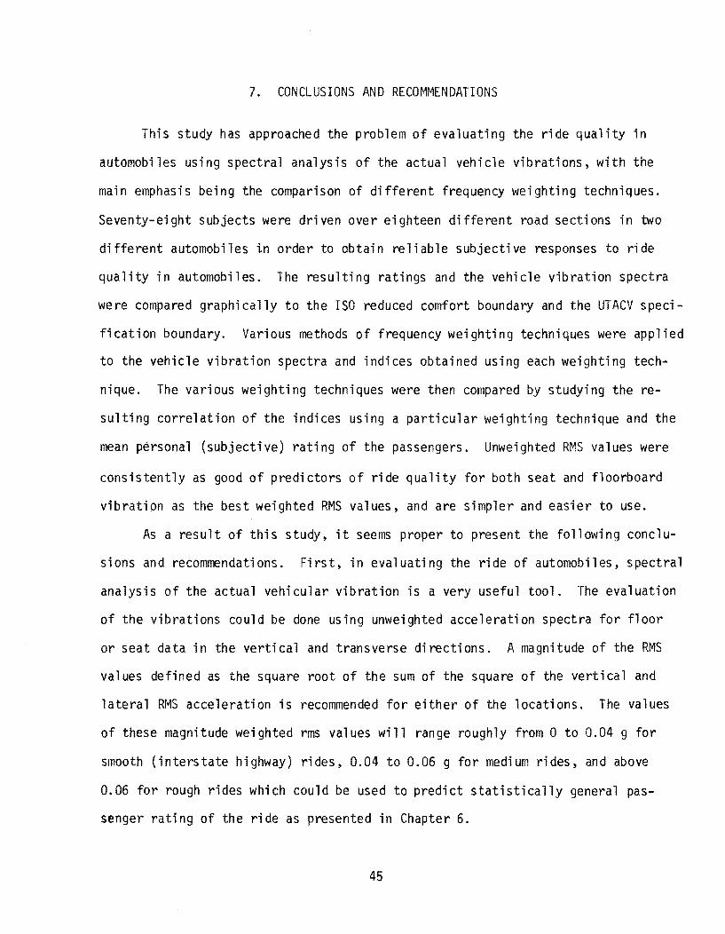
7. CONCLUSIONS AND RECOMMENDATIONS
This study has approached the problem of evaluating the ride quality in
automobiles using spectral analysis of the actual vehicle vibrations, with the
main emphasis being the comparison of different frequency weighting techniques.
Seventy-eight subjects were driven over eighteen different road sections in two
different automobiles i.n order to obtain reliable subjective responses to ride
quality in automobiles. The resulting ratings and the vehicle vibration spectra
were compared graphi cally to the ISO reduced comfort boundary and the UTACV speci
fication boundary. Various methods of frequency weighting techniques were applied
to the vehicle vibration spectra and indices obtained using each weighting tech
nique. The various weighting techniques were then compared by studying the re
sulting correlation of the indices using a particular weighting technique and the
mean personal (subjective) rating of the passengers. Unweighted R~'S values were
consistently as good of predictors of ride quality for both seat and floorboard
vibration as the best weighted RMS values, and are simpler and easier to use.
As a result of this study, it seems proper to present the following conclu
sions and recommendations. First, in evaluating the ride of automobiles, spectral
analysis of the actual vehicular vibration is a very useful tool. The evaluation
of the vibrations could be done using unweighted acceleration spectra for floor
or seat data in the vertical and transverse directions. A magnitude of the RMS
values defined as the square root of the sum of the square of the vertical and
lateral RMS acceleration is recommended for either of the locations. The values
of these magnitude weighted rms values will range roughly from 0 to 0.04 g for
smooth (interstate highway) rides, 0.04 to 0.06 g for medium rides, and above
0.06 for rough rides which could be used to predict statistically general pas
senger rating of the ride as presented in Chapter 6.
45
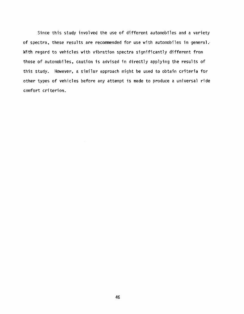
Since this study involved the use of different automobiles and a variety
of spectra, these results are recommended for use with automobiles in general.
With regard to vehicles with vibration spectra significantly different from
those of automobiles, caution is advised in directly applying the results of
this study. However, a similar approach might be used to obtain criteria for
other types of vehicles before any attempt is made to produce a universal ride
comfort criterion.
46

1.
2.
3.
4.
5.
6.
7.
8.
9.
10.
REFERENCES
Roberts, F. L.,and Hudson, W. R., IIPavement Serviceability Equations Using the Surface Dynamics Profilometer, Research Report 73-3, Center for Highway Research, The Uni versi ty of Texas at Austi n, Apri 1 1970.
Anonymous, "A Guide to the Evaluation of Human Exposure to Whole Body Vibration", ISO/DIS 2631, International Organization for Standardization, New York, 1972.
Lee, R. A. and Pradko, F., IIAnalytical Analysis of Human Vibration", S.A.E. . , Transactlons 680091, 1968, pp. 346-370.
Anonymous, IIDesign Specifications for Urban Tracked Air Cushion Vehicles", U. S. Department of Transportation, Washington, D. C., 1972.
Jane\>/ay, R. N., "Vehicle Vibration Limits to Fit he Passenger", S.A.E. J., Volume 56, August, 1948, pp. 48-49.
Dieckmann, D., "Einfluss Vertikaler Mechanischer Schwingungen auf den Menschen", Inernat. Z. Angew-Physiol. 16, 1957, pp. 519-564.
Healey, A. J., "Passenger Response to Random Vibration in Transportation Vehicles - A Literature Review", Research Report RR-30, Council for Advanced Transportation Studies, University of Texas, June 1975.
Butkunas, A. A., "Power Spectral Density and Ride Evaluation", S.A.E. Transactions No. 660138, 1966, p. 681-687.
Spangler, E. B. and Kelly, vI. J., "GMR Road Profilometer - A Method for Measuring Road Profiles", Research Report GMR-452, General Motors, December, 1964.
Smith, C. C. "On Using the ISO Standard to Evaluate the Ride Quality of BroadBand Vibration Spectra in Transportation Vehicles", ASME Transactions, Journal of Dynamic Systems, Measurement and Control, Vol. 98, Series G, No.4, December, , 976.
47

A P PEN 0 I X A
COf'llPUTATION OF POWER SPECTRAL DENSITY
A.l. Introduction
The signals processed in this work were measured acceleration time
series, with sampled values at discrete intervals. A measure of the frequency
content of the random signals is provided by estimation of their power spectral
density (PSD). The PSD is an averaged measure of the square of the signal ampli
tude contained in a narrow frequency band divided by the bandwidth. For each
acceleration trace, a total of 4096 data points were taken at a sampling rate
of 434 hertz, corresponding to about 9.44 seconds of data per trace.
A.2 Detrending
Since the profiles of the roadway test sections used contain no
significant grades, the linear trend of the acceleration traces is small.
Care was taken, however, to insure that the acceleration traces had zero
mean. This was accomplished by the operation
Xk = (Xk)old _ X
_ 1 N-l ( ) where the mean X = N E Xk old
K=Q
48

The resulting sequence
is analyzed for its power spectral composition. The auto correlation defined
as 1 N-l
C(r) = -N E xk · xk+r k=Q
A.3 Power Spectrum Calculations
(A.2)
The two sided power spectral density is then given by the discrete
Fourier transform of C(r).
1 N-l _j2nrk/N G(k) = N r~Q C(r)e (A.3)
If the original sequence xk is real, P(k) will be complex with
a real and imaginary part being symmetric and anti-symmetric respectively,
about the N/2 point.
Taking advantage of the Fast Fourier Transform Algorithm14, it is
better to compute the FFT of xk' using the property that the transform of a
convoluted sequence is the product of the individual transforms with its
conjugate so that if
N-l x - 1 E
(k) - N r=Q
the power density is
_j2nrk/N x e
r (A.4)
(A.5)
where Tr = the total time of the trace included to reconstitute dimensional
units in the power function. The one sided power spectral density is then
49

defined as
P(k) = 2G(k)
A.4 Data Averaging
N k=O,l, .. "2 (A.5)
The sampling frequency for the data was 434 hertz and the incremental
discretion frequency was about 0.106 hertz. Averaging over d incremental bands
yielding d degrees of freedom for each averaged power computation, the power
spectral sequence
P --p --p o k n
converts to the data smoothed sequence
According to
p = 1 k+d k (2d+l)k~d Pk k=d to N-l-d.
The frequency associated with Pk still remains at k/L cycles/ft.
While equation (9) smoothes the data, total power is not conserved in the
smoothing process. The errors are introducted by the failure to include points
in the smoothed array for k<d and k>(N-l-d). With typical spectra this error
is small. Total power error is given by
,,=2d Total Power Error = 1 (2d+l) X:O (2d-A) (p,,+ PN-l-,,)
50

APPENDIX B
RATING FORM
1. How would you rate the car ride you have just taken?
worst ri de I can think of
2 3 4
2. How would you rate your mood right now?
worst mood I can think of
1 2 3 4
5
5
3. How would you rate the weather right now?
worst weather I can think of
Your name
1 2 3 4 5
date
51
bes t ri de I can thi nk of
best mood I can thi nk of
best weather I can think of
secti on number

APPENDIX C
SPECTRAL DENSITY PLOTS
52

BUICK FLOOR VIBRATIONS
-I
Cl :z: cr
• CDi'
:z: ,......~
"....J IJJ Ll Ll
t 0 cREQUENCY (HZ)
U1 t l TICAL ex: ~~ttON 1
~ ~ ."''''' ....... , -".---.-, ...-1 .... " .... !,..b-l--r---",---,-I-.I--,I"lrr'T1~ b 2 ;-
FREQUENCY rHZJ
53
-I
UJ_ CL U1
C"o: I
UJ_ :::a <:::) SECTION 1 CLIP
I ... ATERAL ? I- I 1IIIIIIb I 1111mb 111""'b'"
1 b- I ' 0 ' I I "
-..1-IJJ U U cr
cREQUENCY (HZ)
CREQUENCY (HZ)

.... I
"""0
CJ z: a: CDi'
-z
.-I .... UJ U U cr
. 0
J:'RI=QUENCY
~& ~ ~ ~~~ ~
1 1
J:'REQUENCY
BUI CK FLOOR VIBRATIONS
.... I
Cl z: cr CDi'
......
z:
.-I .... UJ U U cr .. (J? I
z:::~ a:
(HZ)
54
. 0
J:'REQUENCY
~ ~"t-
.... e;,<.:':.
~
~.,.",.,.~.,.~ ~
~~
~
• 1
J::RFOUENCY
~
~
~.,.~~ ~
( HZ )

... I
>- .
w_ a... (f)
Cl z: cr eel
..... :z:
--1-UJ W W cr
~~ ~ ~
1 1
FREQUENCY
BUICK FLOOR VIBRATIONS
~~ ~
( HZ J
55
-I
w ... a... (f)
Cl z: cr eel
......
:z
--1-UJ W W cr
~
~~ ~
~~~ ~'"
3
1 1 2
FREQUENCY (HZ)

-I
a z: cr: co
I
..... z:
-1-l.W W W cr:
1 FREQUENCY
~
BUICK FLOOR VIBRATIONS
....
a z: cr: co ....
I
I
<" ~ ~~~~~
...... ~ ~~ ~ ~
z: ~~~
1 1
FREQUENCY (HZ)
56
SECTJON 0 LATE.RAL
I 0 FREQUENCY
~ ~~ ~~
~ ~ ~ ~~~~ ~
~
~
1 1
FREQUENCY (HZ)
~~
1 2

11
:;P
""')
V
'
:::0
........
<#
....
......
11
no
<#
a
;t)z
~
c r
<#
en
rn
z_
n -<
:::r:
N
~ ~
II.)
<.n ""'"
11
r~
"" :::
0 fT
I ..
..
~
:;P
•
11
::1
:>0
~
p rz
<)
C
en
~
rn
~
<# ~
--1
::r::
~
N
~
~ ~
~
~
li.)
"'.5' 1:
) <'
\
~
\
( G)
InO
1'1
::0
rn_
P
o
Co
rn
z C
l -<
;:x; -
I ~ ~
1'1
:JJ rn
p Co
,
rn
z 'I
-<
..... a:- I\
.)
~-
y,p-
o;!
C .......
n "'-~
'\P
A
.."
r 0 o.
;0
<
.......
o;!
;0
~
.......
0 :z
Vl
en
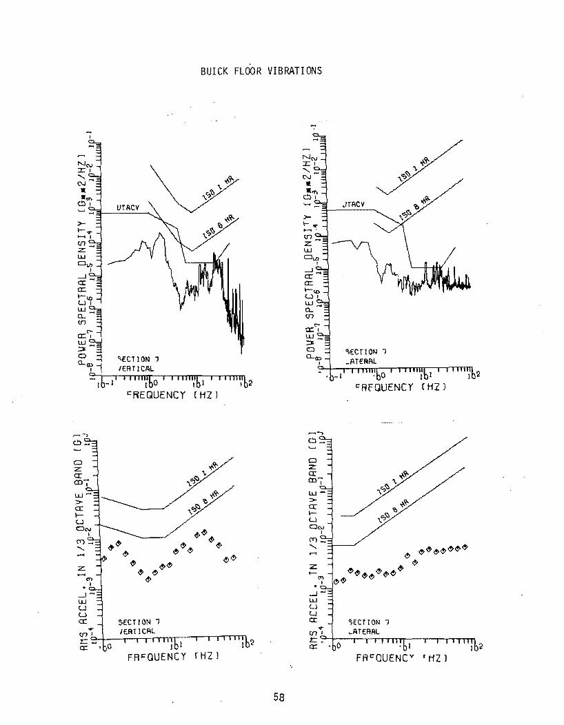
w_ Oo. m
BUICK FLOOR VIBRATIONS
1
cREGUENCY
1 1
FRcQUENCY [HZ)
58
CJ z a:-CO
l
......JW U U a:-
, 0
I:"RfGUENCY
1

..... I
~Ql. en .....
I
......
z
--1-lJ.J LJ U cr:
J 0 FREQUENCY
~
<'>
~ <,><'>
~
1 I
FREQUENCY
BUICK FLOOR VIBRATIONS
~
~ ~~ ~
<'> ~
( HZ J
59
..... I
o z cr: en .....
I
......
z
--1-lJ.J U U cr:
1 0
FREQUENCY
~~
~<"~~~ ~~
~<"
SECT/ON a
1 !
FREQUENCY
~~
~~~~ ~
(HZ)

.... !
BUICK FLOOR VIBRATIONS
1 1
FRfQUENCY rH2)
60
.... I
......
z:
---1-LU U U a::
1 0 C"REQUENCY
~ oe> ~ <!>~~ ~~~
~~o!>
9
I 1
FREQUENCY
~~
~~ ~ ~
~
(HZ)

-I
--.J_ cr a::
W_ Q...
en
Cl Z cr coI
........
Z
--.J-W U U cr
1 0
FREQUENCY
<!>
1 1
FREQUENCY
BUICK FLOOR VIBRATIONS
<!> <!> <!> <!> <!> <!>
<!>
[ HZ )
61
-I ~~ N(\J ::r: I
--.J_ cr a::
W_ CL en
........
Z
--.J-W U U cr
SECT! ON 31
<!> ~ ~
1 0 FREQUENCY
~~ <!> ~
~~ ~ ~~ <!><!>
3')
1 1
~<!><!><!>
FREQUENCY (HZ)
<!>

-I
CJ z: cr enI
..... :z
--1-\J..1 U U cr ... VII
1 0 FREQUENCY
1 1
FREQUENCY
BUICK FLOOR VIBRATIONS
<!> <!>
~
r HZ)
62
.... I
w .... a.... VI
CJ Z cr en ....
t
..... z:
1 0 FREQUENCY
<!><!>
<!><!><!><!>
<!><!>
39
1 1
I=REQUENCY
<!>
<!>
~.,.<!><!> <!>
(HZ)
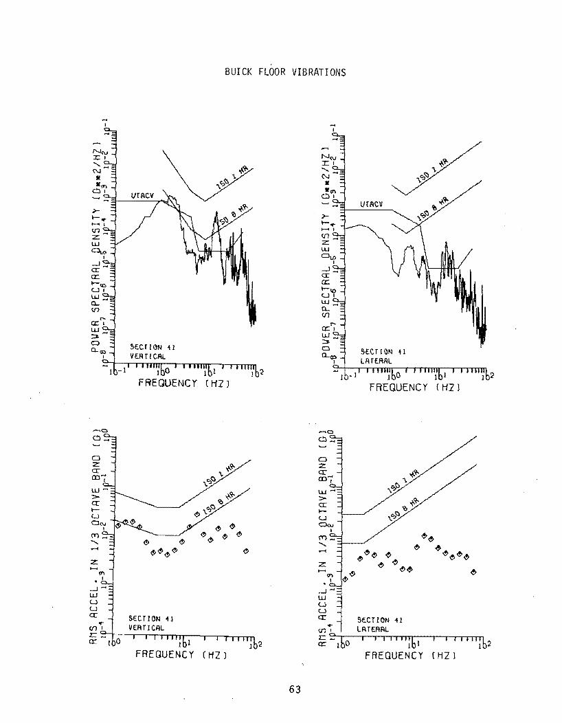
... I
--' .... a::-a:
o z: a::en ....
I
UJ>a::~
u
z:
....JUJ U U a::-
BUICK FLOOR VIBRATIONS
1 1
FREQUENCY (HZ)
63
... I
UJ .... (L
c.n
o z: a::en'"' I
z:
....JUJ U U a::-
SteT ION -41 LATtAAL
I 0 1 I
fREQUENCY (ti21
I 1
FREQUENCY (HZ)

Cl z: a: co ..... ,
.......
z:
-1-W W U a:
" " """ "" " e>
J I C"REQUENCY
MAVERICK FLOOR VIBRATIONS
~"" ""
r HZ)
64
Cl z:: a:
..... I
COj'
.......
z:
-1-W W u a:
" " " " "" "" "
I 1
FREQUENCY (HZ 1
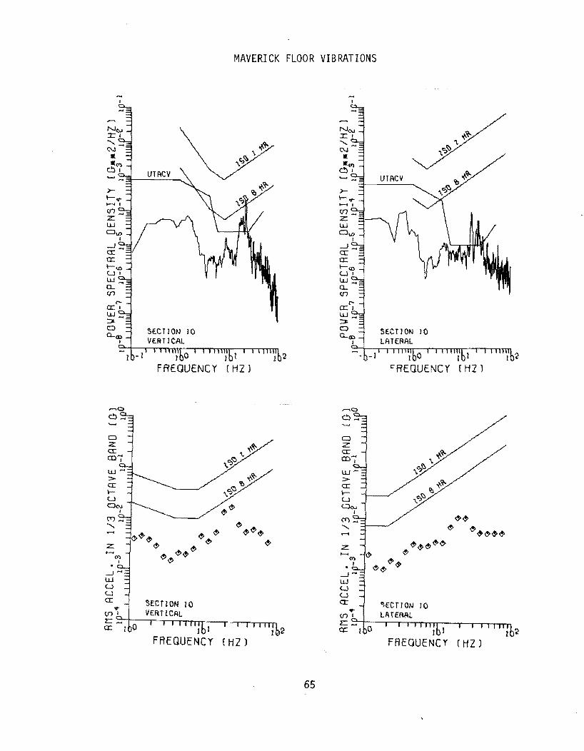
.... I
...J .... 0:: a:
w .... e.. en
Cl z: 0:: (0-;'
......
Z
.....J"" w u u a:
1 0
FREQUENCY
~ ~~
~ ~~~
~~
1 I
FREQUENCY
MAVERICK FLOOR VIBRATIONS
Cl z:. 0:: (0-;'
.......
z:. ~
SE.CTION 10
I
I:"REQUENCY
~
~ ~~",,,,~
<J> ...J-
~<J> ¢>
w u u a: 10
1 I
(HZ) FREQUENCY
65
~~
~~~~'"
( HZ)

MAVERICK FLOOR VIBRATIONS
ta: I
w_ ~
~ ~ECTION I~ a....~ IERTlCAL
':: I b- I i i 1111%0 I I 1\ lIIib! I I \llIIib2 s:"REQUENCY fHZ)
~a
0 z cr m-I
~~
<!»~ I!> I!>~I!>I!> ....... ~ I!> <!» z ~I!>~ ~
.-1-UJ (J (J
cr
I 1
s:"REOUENCY 'HZ)
-I
0 z cr co"'" I
.......
z
.-1-UJ (J (J
cr
66
o,FCTION H LATERAL
1 0 1
s:"REQUENCY {HZ r
~ ~I!>
~I!> I!>~~~
H
I I
FREQUENCv 'HZ)
..
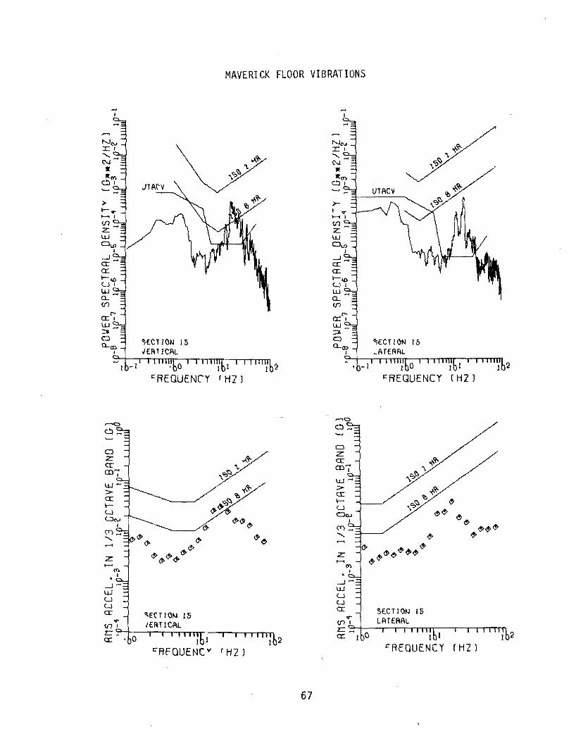
.-< <" z
...J"'" UJ U U a::
• 0
~REQUEN(,Y
~
<"
($>($><"<" ~($>
1 1 C"AfQUENCY
MAVERICK FLOOR VIBRATIONS
r H2 J
67
a z a:: ro
I
...J .... UJ U u a::
I 0
~REQUENCY

o :z:: ex: en'" I
......
:z::
.....J-W U U cr:
.". V11 2:=:_ 0;:: T
MAVERICK FLOOR VIBRATIONS
1 1 1
FREQUENCY (HZ)
""e>e>e>"
I 1
I=REQUENCY r HZ)
68
.... I
Cl :z:: ex: en,"":
......
.,. V11 2:=:_ 0;::
1 0 I=REQUENCY
,," "
~.,.,.,<$'e>.,.," .,
SECT I ON i5
1 I
I:"REQUENCY
" ""
e> ~~
fHZ)
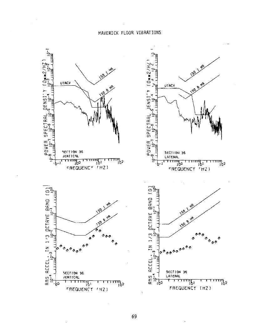
(G) I
11"1
0·
1 I lI
lill
j I 11
1~11
I
I 11
111
~
....
...p
<)
" ""'
''''' ~
" :;
pn
:::
0 ....
.....
~
:u
m ..
.. m
n
o
~
00
0
»z
~
?ii OJ
(o
j c:
r
~
a>
(oj
r11
<7)
~
Z
Z_
~
Cl
r)
-<
<
~
~] ~'\
3::
~
):>
::r:
: ~
<:
N
'\lIo
rrl
~
:::0
<t
t-I
("")
~
A
~
.,., '"
I '"
0 0 .
0'1
:::0
1.0
<:
t-I
co
:::0 ~
t-I
0 Z
(J')
~
--i ~
,n
)
1,-rt
ll
~
11
»"'
" <t
."
....
. n
:u
:::0
""' .....
<t
m
....
:;p
-m
:1
:>0
~
00
0
rz
<t
?ii OJ
(o
j c:
<&
I ~
a>
r11
a>
~
Z
Z_
<t
C
l C
l <
) -<
-<
.....
<t
<t
::r:
: ~
<t
~
N
~
~ ~ ~
cr
'" '"

MAVERICK FLOOR VIBRATIONS
.... I
seCT ION '38
w_ ::r. <::)
e.. <If VERTICAL
~lb-l' I IIII~bo I 111"%1 ' 11l1l~b2 E::REQUENCY (HZ)
1 !
E::REGUENCY (HZ)
70
.... I
w_ e.. (f")
LATERAL
I I I I "; b! I I I I II ~ 62 E::REGUENCY r HZ)

-,
w_ a.. 01
C)
z: a: (Il
I
......
z:
-.J-w u u a:
I 1
I:AEOUENCY
MAVERICK FLOOR VIBRATIONS
~~~ ~~
r H2 J
71
w_ a.. 01
......
z:
~1 OI~l :cO 0: - 'bo
1 0 I:REQUE~Cv
<:';f("T 1 ON 39 LATERAL
I 1 I "'lbl I:AEOUENCY
~~~~~
, 1111I;b2
rH2J

w_ 0-m
Cl Z CI:" CO ....
I
z
-1-W U U CI:"
1 0 c~EQUENCY
MAVERICK FLOOR VIBRATIONS
72
-I
Cl Z CI:" co'";'
z
-1-W U U CI:" ~fcrlON .f0
u~rEAAL
I I , ", ;bl FREQUENC Y r Hl )

MAVERICK SEAT VIBRATIONS
.... I
o z a: (0 ....
I
-1-UJ U U a:
1 0 C'REQUENCY
~ECrzON 9 (f) "': LA-ERA ...
~~tbrO---r~I-rI~I~I~I~ll~b-l--'--'~I~1~1~1~1~;b2
C'9C'OUENCv r'iZJ
73
a z a: (0-:'
-1-UJ U U a:
1 0
C'REQUENCY
,,£c r I ON 9
1 1
FREOUENCY r HZ)

MAVERICK SEAT VIBRATIONS
-I
a z: a:: CD ....
I
.u->-:r
,..... ,,<!J<!J ~<!J~ ~ ~~ ......
z: ~~ ~ <!J~ ~ <!J~ ~~
---1 .... ..u :..J :..J :r
1 t J:AfOUENCY rH2J
74
1 0 C"REGUENry
~~ ~'\
,\e:J
~~ ~'O
'\~
<!J<!J
<!J<!J~
<!J<!J<!J~~<!J
10
t I
C"AFOUENCY
e>e> ~ ~ ~
~ ~
fH2J

... I
'""""
Cl Z cr CO"':'
.......
z:
...JW U U a:
MAVERICK SEAT VIBRATIONS
1 0 t::AEQUENCv
1 1
cAFOUENCv ''12)
75
W ... 0-en
,.....0
c ....
Cl Z cr col'
z:
...J ~ . w u u cr
~~~ ~ ~~~
~ ~
C>~~~~~~~ ~~
' ..
1 1
cAEOUENCY r ti2)

..... I
lU ..... 0... tf1
MAVERICK SEAT VIBRATIONS
t,r:r'10N 15 JE.RT· Cf.\L
I I 11I1;bl I I 111I1b'.: t:'Rt:'QUENCY '''iZl
76
..... ,
lU_ 0... tf1
a z: cr: CDI' lU::>cr: lLl
....JlU Ll Ll cr:
~~~
~ ~~~ ~ ~
<!')<!'><!'><!'>
<;t><!')<!'>~~
1 1
t:'RfQUEN(Y 'HZ)

.... I
Cl z: a: co .....
--.JLU W W a::
. 0
r~EOJfNrv
MAVERICK SEAT VIBRATIONS
77
Cl z: a: co .....
I
--.JW W W a::
. 0
cf1EOLJENrv
• 1
t:'RFQUENr v 'HZ)

'-J
CO
o
n :JJ
."
o c..
m
Z.
r')
<
::r:
N
I\)
-I>
..
" .,
::I).,
1 i
fQ
::
bZ
r
co>
(1)
I:) I:)
Qo
~
~
(;I Qo
(;I
I:)
~
~
~
RM
S A
CC
EL.
TN
1
1"1
..n
o
1"1
Cl
C
."
Z.
n <
...c
N
'0 ..
. 11
'1-'
;
r I>
::b
...
, (")
,., ::I)
::
bQ
f"
..
::
W
(1)
I:) I:
) Go
~ I:)
Qo
~
~
~
Qo
(G 1
In
O
11 ..0
m
0_
c.
.O
1'1
L
. r')
<
'1 :u 11 o C
."
Z
'I
<
::r:
N
I\)
I\)
-1
3':
):
:>
<:
ITt
:;:0
.....
.. ("
"')
A
V>
ITt
)::>
-I
<:
.......
O::l
~ .......
§E
V>

-I
o z a: en,
-1-\.U W W a:
MAVERICK SEAT VIBRATIONS
I 0 FREQUENCY
1 I
FREQUENCY (HZ)
79
..... I
J ()
FREQUE.NCY
I I
FREQUENCY (HZ)

.... J
w_ e.. (J")
a z: cr CD
I
.......
z:
-..I .... W W W cr
1 I
FREOUENCY
MAVERICK SEAT VIBRATIONS
~ ~&& " "
(HZ)
80
.... J
w_ e.. (J")
a z: cr CD
f
.......
z:
-..1-W W W cr SECTJON 39
I I I::REOUENCY ( HZ J

Cl z: a: m'";'
I 0 t:AEQUEN[Y
MAVERICK SEAT VIBRATIONS
81
UJ .... a.... (J')
Cl z a: mI
I 0 t:AEQUENCY

APPENDIX D
WEIGHTED INDICES
82
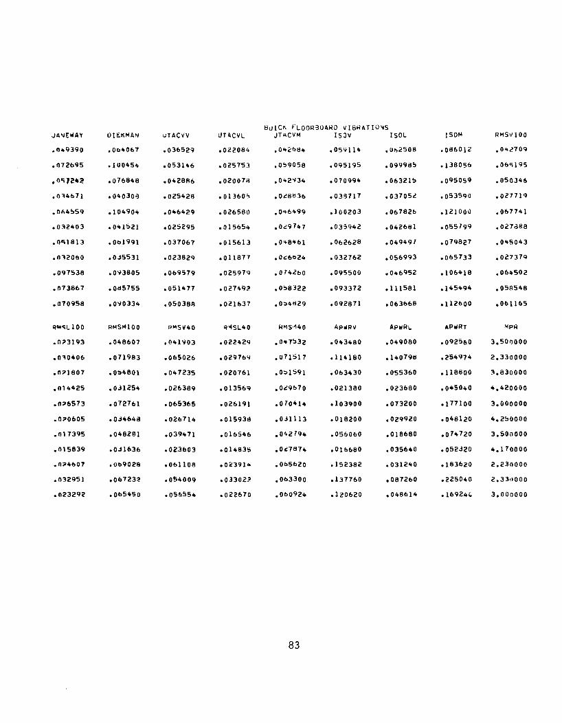
~uIC~ FLOORBU4RD VIBRATIO~S JA'IIEWAY UIt.KMAN uTACVV UT4CVL UTIICVM ISJV ISOL ISOM RMSVI00
.1149390 .0040&7 .03&529 .02208'. .0421:>84 .05'1114 ,Ul:>2508 .08&012 .04<!70~
.n72695 .100454 .053146 .025753 .0:'9058 .095195 .09998~ .138056 .06<;195
.1IC;1C!·~ .076848 .042886 .020076 .042'134 .070994 .06321~ .095059 .050346
.11:14071 .0403013 .025428 .013&0'> .0c'81:l30 .039717 .03705': .053590 .027719
.Ob4~59 .104904 .0464<'9 .026580 .0 46499 .100203 .067826 .121000 .067741
.0~2403 .0"1!:)21 .025295 .015654 .0.::9747 .035942 .042661 .055799 .027088
.n"i1813 .001991 .037067 .015613 .0<+8'+61 .062628 .049497 .079827 .045043
.0:12000 .O.j5531 .023829 .011877 .0'::6024 .032762 .056993 .065733 .027379
.097!:o38 .0<;3805 .069579 .025979 .074260 .095500 .046952 .106418 .064502
.073867 .Od5755 .051477 .027492 .0:'8322 .093372 .111581 .145494 .O!:o8548
.070958 .0'10334 .050388 .021&37 .0~4829 .092871 .063068 .}12000 .061165
QI4~LlOO RMSMI00 RMSV40 R"'S1..40 RMS'~40 API/FIV APWRI.. APiJlRT MPR
.0;>3193 .048607 .041903 .02242Q .0"7:'32 .043480 .049080 .092560 3.501J00O
.n:10406 .071983 .065026 .029769 .071517 .114180 • 14079tl .254974 2.330000
.0;>1807 .0::'4801 .047235 .020761 .0~1591 .063430 .055360 .118800 :'1.830000
.n14425 .OJ1254 .026389 .013569 .0.:'9070 .021380 .023680 .045040 4.420000
.0;>6573 .072761 .065365 .026191 .070414 .103900 .073200 .177100 3.000000
.n;>0605 .OJ4648 .026714 .015938 .0.'1113 .018200 .029920 .048120 4.250000
.017395 .048281 .039471 .01&546 .0'+2794 .05&060 .018680 .014720 3.500000
.015839 .OJ1630 .023603 .014835 .0c'7874 .01&680 .035640 .052J20 4.170000
.0;>4007 .009028 .061108 .0<13914 .005020 .152382 .031240 .183620 2.230000
.032951 .06723::.- .054009 .033022 .003300 .131760 .081260 .225040 2.330000
.023292 .005450 .05&554 .022670 .000924 .120620 .0486}4 .16924(, 3.000000
83

~AVER!CK FLOO~~OARD VI8RATIO~S JAIIIEwAV OIt;:KMAN UTACVV UTACVL UTACVM ISOV ISOL ISOM ~MSvl00
.0107344 .0 .. 8536 .031ob03 .023834 .0'+2iH6 .0101079 .077251:1 .0871097 .032272
.0102725 .0 .. 4237 .032032 .02102510 .0"0150 .035785 .0103961.i .056696 .029826
.01ob157 .0:>6908 .0:.13602 .0261313 .0"2<,184 .054645 .061702 .0824 20 .037689
.OR9548 .01:$8483 .0657010 .0:;521.., .0051;;14 .073412 .090736 .116715 .05888A
• o 719!)4 .Od81008 .049926 .030~U .0:'8721 .0910950 .033616 .100720 .0577102
.00:;1204 .0:.1421 .037977 .024763 .0"5.3"0 .041861 .050063 .065252 .035016
.01'15621 .099843 .061313 .057527 .01:$4075 .099893 .169}40 .196434 .064751
.076502 .01.i5800 .OSS.:?41 .048865 ,013751 ,084027 .1595910 .180369 .055946
.065436 .071587 .052199 .037870 .Ob41088 .061476 .094045 .112355 .047217
Q"'C;L100 RMSM100 RMSV40 Q'4SL40 RMS"40 Ap.RV APWRL APiIIRT MPR
.0;;>5824 .0101.337 .031268 .0210183 .0.39'+99 .025676 .072268 .09 7940 4.090000
.0;;>10466 .0.38608 .028157 .0223105 .0-'5':163 .019360 .0354100 .054800 10.070000
.0::07011 .046386 .0371:116 .025597 .0"5679 .0397100 .049856 .129340 3.850000
.00:;0954 .077881 .055904 .0107815 .013:;67 .086880 .134710 .221580 2.720000
.0::06729 .Ob3640 .055649 .02&743 .Obl145 .1311060 .015436 .146900 2.5100000
.0::05173 .0 .. 3105 .033291 .02278:.1 .010 0J05 .028000 .034894 .062900 3.800000
.00:;8973 .01:17611 .062466 .058520 .Od5b02 .141600 .439008 .594868 2.200000
.00:;2750 .076863 .0510645 .0521810 .0(5:'61 .1010280 .3572100 .1061540 2.670000
.0-.7760 .Ob0500 .0105227 .036190 .0:.7':126 .051580 .1029100 .1510500 3.390000
84

MAvERICK A'lD S,JlC>< FLQORdUA~D VISR4TIQ'lS JAI\IEwAY DH.KMAN UTACVV UTACVL UT .. CVM IS:>V ISOL ISOM I-/"'S\l100 .049390 .004067 .03652'9 .022084 .0'+21:>84 .059114 .062501:1 .08601l .042709 .012695 .lU0454 .053146 .025753 .0::>9058 .095195 .099985 • 1380">/) .0/)'5190; .0C;7.!42 .0/61:148 .0421:186 .020078 .0'+2':134 .070994 .01'>3215 .095059 .050146 .014671 .040J08 .025421'1 .013605 .0"1:18 36 .038717 .03705i .053590 .027719 .064559 .104904 .04&429 .02658\l .046,+99 .100203 .0&7826 .121000 .01>7741 .032403 .0<+1521 .025295 .015654 .Oi9747 .035942 .042&81 .05579'1 .0278811 .0 .. 1813 .001991 .0370&7 .015&13 .0'+8 461 .062628 .049497 .079827 .04';043 .0'12060 .OJ5~31 .0231:129 .011877 .Oi6024 .0327&2 .05&993 .0&5733 .0.!7379 .097538 .0"31:105 .069579 .02597Q .0/4260 .095500 .04695i .10&'+11:1 .004502 .073867 .01:15755 .051477 .027492 .0::>8322 .093372 .111581 .145494 .051'\541'1 .070958 .0'10334 .050J88 .021&37 .0::>4829 .092871 .063661:1 .1126 00 .0/)110') .047344 .048536 .034&03 .023834 .0420lb .041079 .071258 .Otl7497 .032272 .042725 .044237 .032032 .024254 .040150 .035785 .0439&1:1 .OS&b96 .02Q826 .046157 .05&908 .033602 .026813 .042984 .054645 .0&1702 .082420 .037689 .OA9548 .01:18483 .065704 .055212 .01:151:114 .073412 .090736 .11&715 .051'1888 .01}954 .01:18408 .049926 .030913 .058121 .094950 .033016 0100120 .057742 .00;1l04 .0::'1421 .037917 .0247&3 .0 .. 5340 .041861 .0500&3 .0&5252 .03 .. 016 .01'15621 .0"'9843 .061J13 .057527 .004075 .099893 .169140 .19&434 .064751 .01&502 .01:15800 .055241 .04886,) .073751 .084027 .159594 .180369 .05'594& .01'15436 .071587 .052199 .037870 .004 4 88 .001476 .094045 .112355 .041277
RM<iLI00 RM:iM100 RMSV40 Q14SL40 R"IS>140 APoiRV APi/RI.. I\PwRT MPR .0"3193 .048607 .041903 .022429 .047:>32 .043480 .049080 .092560 3.5uOOOO .0~0406 .071Oi83 .065026 .029769 .0(1517 .114180 .140798 .254974 2.330000 .0"1807 .0!:>4801 .047235 .0207"1 .0::>1:>91 .063430 .0553bO .118800 )\.830000 .014425 .0';1254 .02&389 .0135&9 .0,'1070 .021380 .023680 .04 5040 4.420000 .0"0573 .0727&1 .065;1&5 .02&191 .0/04 14 .103900 .073200 .177100 3.000000 .0"0605 .OJ4648 .02&714 • 01593~ .0.:11113 .018200 .029920 .048120 4.2~0000 .017395 .048281 .039H1 .01b546 .0'+2194 .05&0&0 .018.,80 .014720 3.500000 .015839 .OJ1031> .023003 .014835 .0.:7<174 .OU.>680 .035&40 .052320 4.1 7 0000 .0"4607 .00902A .061108 .023914 .005620 .152382 .031240 .183620 2.230000 .0'12951 .007Z32 .054009 .033022 .003300 .1317&0 .0872&0 .225040 2.330000 .023292 .005450 .05&554 .022670 .000'124 .120620 .048014 .169240 3.000000 .0"5824 .041337 .031268 .024183 .0';9"'99 .02567& .072268 .097940 4.090000 .0"4466 .0';860!! .028157 .022345 .OJ5'163 .0193&0 .035440 .054t100 4.070000 .n"7011 .046381'1 .037816 .025597 .0 .. 5079 .039740 .04985& .129340 3.850000 .00;0954 .0T7t181 .055904 .047815 .0/3-:'67 .08&880 .134110 .221580 ?720000 .0"6729 .003640 .055649 .02&743 .001 1 45 .1314&0 .015430 .146900 2.54nOOO .0 .. 5173 .043105 .033291 .02278'3 .0'+0305 .028000 .034894 .062900 3.800000 .n0;8973 .01$7&11 .0624&6 .058520 .01;)5002 .141600 .439008 .594868 2.200000 .00;2750 .076863 .054&45 .0:;2184 .0/5561 .104280 .357240 .4&1:>40 2.1)70000 .n'l7160 .000500 .045227 .03b190 .0::>7"'2& .051580 .102940 .1545CO 3.390000
85

MAVf.RICK SI:.A' VlliHATIONS ,JANE WA Y LlEK"AN tJTACVV lJT~CVL U1ACV~ ISOV lSOL IS0M R~SVlOC
.Olq339 .029045 .011780 .O?q515 .03J7R3 .03724R .073171 .0l:l210b .018767
.02007" .026331 .012Q12 .011707 .034252 .033530 .061655 .070183 .017352
.028001 .04q546 .017862 .030773 .035582 .0!:>8449 .070138 .O9130() .031834
.036509 .044061 .025456 .0C,R322 .063640 .04<1978 .108230 .11 q2l , .0292~i\
.045632 .072461 .028638 .04Q087 .067599 .090389 .174259 .196307 .046457
.017573 .023695 .010974 .035949 .0375QO .030391 .054518 .Ob24l6 .015740
.042653 .086tl49 !026 022 .O'iQ567 .0649Q7 !100008 .198343 .222131 .055409
.036789 .067190 !021524 .04QS26 .053990; .0!:!3335 .129365 .1~3866 .043544
.022466 .04409i/ .014602 .043374 .045764 ~047539 .09538<1 .106578 .028737
RMSLlOO RMSMI00 RMSV40 RM<iL40 RMSM40 Alo'wRV APwRL APWRT MPR
.030250 • o 35!:>96 .018212 .0?Q006 .0342Fll .032060 .039960 .072000 4.090000
.03221f:> .036<;:,86 .0171b9 .0;>Q515 .034139 .025Q20 .044260 .070180 4.070000
.n31693 .0441,101 .033333 .07Q090 .044237 .0';)4300 .047140 .101440 3.850000
.058874 .065747 .028595 .053811 .060Q3~ .006180 -137360 .203540 2.720000
.055904 .072648 .04717A .054QOO .074755 .1!:>4330 .346960 .~03280 2.540000
.0345'52 .0371,172 .014906 .012159 .03<;440 ~026060 .028400 .054480 3.800000
.064969 .0853911 .0'542<12 .061088 .0!:!3226 .107560 .603640 .771180 2.200000
.050261 .0664Q6 .0431'i10 .047645 .064290 .135680 .258400 .394060 2.670000
.043035 .051746 .028525 .040150 .049257 .041160 0115;>60 • 1 ~6400 3.390000
86

APPENDIX E.l
SCATTERGRAMS
87

WEIGHTED INDICES VS. MEAN PERSONAL RATINGS
0 0 U) IP 0 or: . MAVERICK MAVER!CK 0 Q
SERT SERT Q IP I.D IN Q ... . Q 0
~~ ~§ I!J , . ,-
X O x O \.IJ \.IJ Cl Cl Zo ZIP [!] .... In .... r-
r!J Q [!) C)
n - Cl • W O [!) W O .... .... :r: l@ :r: °0 0 0 ,." .... '" .... w L.J 1.1.10 We> ,...,
(!) :.. ::a '"'" Q I!J 0
Q I!J
[!]! ID IP Q IN ~ ("j :"..1
0 0
0 JANE:\lRY 0 IJIECKnRN 0 0 C? C? ~ 2 3 4 0 1 2 3
nPR MfR
88

o -Q
::I
WEIGHTED INDICES VS. MEAN PERSONAL RATINGS
L!J
{!J
I!l
I!l
RI'1~HO VERT ICAl
nAV<:.RICK SEAl
C!l
~~ ,~ X O LIJ Cl ~<:I .... .,.
Q Cl • LlJO ,.... x °0 w~ =- • o
<:I -o o
<:I '::J co
o 'ID Q
o
o "" o Q
I!l
o o co
RnS10 lATERRl
I!l I!l
MAVERICK SEAT
C!l
RnSiO "AGN lTUDE
~~--~2----~3r----4~--~
nPR
89
MRVERICK SERT
C!l

WEIGHTED INDICES VS. MEAN PERSONAL RATINGS
~~ " . xQ W o Zo .... crt
o o· WO .... :c °0 .... (\1 Wo ::::a •
Q
o .. o o
l!l
(!J L!l
I!J
nRVERICK SERT
L!l l!l
o RMSlOO VERTICAL g
o 1.0 o . Q
~i ::>0 x W o Zoo .... (7)
o o • we .... :c 0 0 .... IN Wo ::::a •
o
o -Q
Q
I!J I!J
L!l
g RM3JOO LRTERRL Q,+-----,------r-----,----.-,
2 3 4 2 3 "PR "PR
0 'II:) e e
0 ..., 0 ':)
~~ ~Q W 0 Zo .... crt
0 o . W" .... :c °0 ..... (\1 WQ ::a e
0 ;; 0
0 c 0 . c,
I!l nRVERJ CK SERT
(!J
RnS100 MAGNJTUDE
3 nPR
90
L!l
4
MAVERICK SERT
[!]

WEIGHTED INDICES VS. MEAN PERSONAL RATINGS
o Ii o
~! , . xQ ILl o Zu> ......
c o . ILl" l-X (!)o -crt ILIa ::a •
Q
\0 -Q
o
I!l
[!J
o J SO V[ RT I CAL
MRVERICK SERT
'I!l
G ~ ~+---~----T---~----' I
4' 2 '3 MPR
Q \0 .. 0
u:o N .. c
~9 , . xc IJ..I 0 ZU) .......
0 o . IJ..IO .... x (!)o "'r..o 1.1.10 ::a
0
\0
~ 0
I!J
I!I
0 ., ~
JSO nAONITUO[
~ '3 MPR
Q Ut
~ ~
Ut
'" --: Q I!I
~g ,--: xQ ILl 0 Zu> .... c-
0 o . ILI~ l-X (!)o -", ILl 0 ::a
0
u> W Q
0
0 Q ISO LRTERRL ~ ~
nRVERJCr; SERT
91
l!l [!J
l!J l!l
4
2 3 MPR
MAVERICK SERT
I!l
l!Jl!l l!l
I!l
4 6

WEIGHTED INDICES VS. MEAN PERSONAL RATINGS
nRV£RICt\ SERT UTACV VERTICAL
<I!J I!J l!J
I!J
3 nPR
l!l
I!I I!I @:1
4
Q '0 Q
Q
Q I.D
~ Q
~~ ,,~ 7o:: Q W co Zoo .... ..,
0 co • wI:> .... :z:: Co ~~ ::a
Q
Q .. a I:>
0 <:3
~
'1
Q
~
MRV£RICK snn U1Rev un ERAl
l!J £!l
~~~--2~----3~----4~--~
MV £R I CK son UTRC'/ MAONI TUDE:
l!J I!J l!J
~
MPR
(!J
92
I1PR

a
I.e> -e . a
WEIGHTED INDICES VS. MEAN PERSONAL RATINGS
r1RVER1CK SEFtT JUtS PYR VERT
I!l
(!]
I!I
2 l MPR
I!l
(!]
I!l IDI!l
4
0 IN
"! a
Q t.O
~ a
~~ -.....;"'! x a UJ c Zoo .... -IN c· UJO .... :r: C!:I o ..... v \&.I .... ::a
0
0 l""-e . a
0 . c e . ~
o
Q toO ...
. o
r.> g
nf\V£'~lCK S(RT hB'S PVR l~T
1!1
l!l
~+-----~----lr-----4~--~
nF\Vf:RJCK sun hBS PYR TOT AI..
l!l
I!l
93
MPR

WEIGHTED INDICES VS. MEAN PERSONAL RATINGS
C '0 g 0/ 0
0 (!] MRVERICK 6 l!J t'ln.VfRI CI'I. I( BUICK • SU1CK
1.0 ..."
b t-o
0 0, • i!1I ~o
I( ~g :II J! ~ [!]
" [!] ,~ :IIq;r ,..;:0 xo,
w w • Q
Mf!Jf!J (;;.)
:r."" If
z..." D .... .,. .. ~ <t" 0
I.!) c:. Q' I( o· I w O I.\J C.) .... Jf l-
f!] r :r 0 0 I ~I.!) 8g G -1'1) 1!J We:) Wo :00 I!l :-.. LlJIE )( 0 0,
llllE )IE U) \J) .... ~.
0 <.> 0 0,
<:> JRNEWRT <:> .rn £.c' K.I'1 ~!..J II c C> ~ 0,
0, ~ 3 .. 0 • 2 3 " ~ ni"A !1PR
94

~
WEIGHTED INDICES VS. MEAN PERSONAL RATINGS
a MPR
.t!J I'\fWf.R I Cit If BUlCK
"
ell OlD C.
0
<::> ..0 c. a
~~ ,~ )<0 ILl c· z(;'\ ..... a c· ILl 0 .... l: 0 0 ..... "V Wo ,.
0
<::> ... 0
a
I!J
)II ,.
I!l L!l
L!l II
" I(
g 'RM!J1 0 L R T {RRl
L!l MAVERICK If BUlCK
c. °1+-----2~----'3-----.----~
I!l I!l MV{R 1 Cit lIE SUlCK
!If 1M I!J !IC
I!lI!J I!J
MPR
Q Rt'I~H 0 nRON IT ODE.
Q Q
~ 3 Mf'R
..
95

§ . Q
o o o
WEIGHTED INDICES VS. MEAN PERSONAL RATINGS
(!] MAVERI Ct(
• HUICt(
I!l [!)
Ht.Jf o .... o . <:;)
l!J MRVf.R I en If au] CK
II lIE
IE l!l Ie Ie
[!)
RnSJ 00 VERTl CAL o g Rn~lOO :"ATfRRl
2 3 .. Mi2>?l
Co t:I> 0
Q
IJ) .... ~ 0
~~ ,~ xQ W Q
%1./> ,.... .....
0 Q • we--, I-:J: Og ..... (Q Wo ::0-
C)
to ... 0
Q
0
B C>j
°1+-----2~j----~i----~1i~--~S
n.Qt\
l!J tH\Vf.R t Cit I( BU1CI!
'RnSlQO MAGN1TUDf.
3 '1f>R
96
s

o to Q
o
o ... Q
o
Q o Q
WEIGHTED INDICES VS. MEAN PERSONAL RATINGS
UTACV V£.RlICAL
III
l!l
wl!J )I C!l J( I!J
III
l!l tHWt:.R I CK Ie aUl CI\
Q
'0 t::>
UTACV lR1ERRL
..
I!l
L!J
I!l
(!J
I!J tUW f. RICK Ie BUICK
o,+----~r-----3~----,-----~ ~+----cr---~3~---4~---'5
MPR
Q .... Q
o
o c::. c::.
UT~CV MRQNlfUO€. l!l I!l I!l t\ 1\.1 t: R 1 CIt
III BUICK
)II t!.l
I!l
~+------'-----3r-----'-----~
'1PR
97
MPR

WEIGHTED INDICES VS. MEAN PERSONAL RATINGS
Ut .... Q . o o
1 SI} Vl.M t CAl
I!l • ". (!] J(
l!l
l!J r\RVf.R1CK Ie SUlCK
(!]
:1 4 & Q+-----~----~----}r----? ~
MPR
Q Q.I -0
0 0 ": 0
~g ,~ x O ILl 0 Zo ..... \0
C) (:) . \LIn ... :z: 0 0 - .. Wo =- .
0
0 'tV
~ 0
(';) It:)
~
~
1 SI} LA t £.RAt I!l
)l
J(
,.
(!]
I!l
I!l
I
:1 MPR
0
"" ": 1S0 nAllNHUO£
0
U>
"" -0
~~ ,. Xo \LI 0 z'w
- r0-o o • \LIn ~ :z: Og .... "" Wg :>
0
Ut C\I 0
0
0 0 ~ °1 2
(!]
3 I1Pft
C!J tlRVf.R I CK IE SUICK
..
98
C!J t\RVf.RICK IE SU1CK
(!)
/!l
If 11. J(L!J
/!lJ( IE

WEIGHTED INDICES VS. MEAN PERSONAL RATINGS
0 Q
PUR lR'T g Ras PI/R VERT .. Res cY C) l!1 nAVE.R I CK ° C!1 MRV[RICn.
J( BUleK I( SUleK y 0 l!1 r"" Q 0
)I[ C'f . Q Q
l1K ~~
I!l ~~ [!) , . J( ,.
~C'I )I( X O
u... W c 0 ZIJ) [!J III Zc .... ~ ~ cv
Q .. o . o . WO [!) WO t- t-:z: :z: C!l o °0 .... ." .... m We
M We ::a ::.. . (")
~ (") • (!J
IJ) • 0 (!] .. [!J .. Q
c::' ME (") l!1(!] 0 • (!]
~Jf Jf 1I~[!Jk a 0 III .l!) IE g 0 [!) c::' ~ 2 3 " .- ~ ~ 3 4 5
nPR ~PR
0 Q Res PUR lQl AL '?
(!) I\AV[RICK C'I l!)
IE BUleK 0 \.D t\I
0
~~ I!J
,. xO ILl 0 Zo -"" .. c . IIJO t-:z: )I( (!I 0 .... 0 )I( [!) W .. ::a •
0 • • 0 l!) l!) YO ~ Q
0 III ['J
IE[!J c £!Jic1E 0 ~ 0, 3 4 5
nPR
99

APPENDIX E.2
CORRELATION COEFFICIENTS AND RIDE INDEX EQUATION
PARAMETERS FOR VARIOUS WEIGHTING FUNCTIONS
100

BUICK FLOORaOA~O VIBRATIO~S JANEWAY DIEKMAN JTACVV UTACVl. UTACVM ISOV ISOL IS)"! Q"ISVI00
CO~=!o rClEF. -.931800! -.A13015 -.923102 -.891460 -.94040i -.910915 -.668122 -.908586 -.899191
GRAOTI"NT -J6.4h9271 -21.891119 -52.511614 -1~8.334291 -51.533293 -21.18456'J -23.359061 -21.214215 -45.6H260
INTE~r.I"PT 5.lt36188 5.341194 5.529381 5.964lt29 3.123465 5.21:16991 4.814282 '5.559114 5.557180
VAI<I A'IIrE .011553 .139948 .0'l(,ltOO .114533 .0&8015 .100H5 .325418 .102104 .112060
STU. f'lI"V. .218483 .314096 .2Q1939 .338421 .2&0911 .316451 .510454 .320415 .334154
RMSl.!OO HMSMI00 R'1SV40 RMSL40 RMSM40 APIIRV APWRL APIIIRT '''PR
COkQ·o r.OEF. -.851281 -.918461 -.892521 -.886858 -.9124&0 -.952232 -.615862 -.934195
GRADYFNT -1.1.8.816446 -45.302011 -45.194381 -1.3.145451 -44.4&9810 -15.228323 -13.925133 -10.068865
0 INTEHrF'PT 6.0358;>3 5.176811 5.435913 5.801&90 5.59101t'J It. 49110 1 1t.014925 4.6431lt6 --'
VAHIA'IIrE .162064 .092084 .119130 .125668 .0~8552 .054895 .365390 .014265
STU. I')F'\I, .402512 .303453 .346021 .354491 .313930 .234i96 .604415 .212515

MAVERICK FLO~H30AR) vlBRATI0~S JAIIIEIilAY DIEKMAN JUCv'I uTAC'IL. UTACVM IS:>V ISOL IS:>M "MS'II00
COH>I. r.OEF. -.938115 -.Q88981 -.8"15696 -.842404 -.88131!> -.912366 -.599135 -.820115 -.988109
GRADIFNT -J8.421011 -34.190113 -51.415921 - .. 4.118305 -35.4!:!620!::i -29.562819 -9.024190 -1;>.431t5~B -54.198450
INTERCFI>T 5.119~30 5.114394 5.675951 4.698818 5.317569 5.188166 4.041108 4.638380 5.812543
VARlAlllr.E .051028 .010430 .0"14104 .138186 .10121:) .025940 .305083 .155301 .011251
STD. flFV. .2381:106 .102128 .306163 0311131+ .31811+3 .lbl05'i1 .552343 .394090 .106012
RMSLlOO >!MSMI00 R'4Sv40 RMSL40 RMSM40 AP.RV APWRL AI>.>lT "PR
COI<R. r.OEF. -.1tl9016 -.950949 -.9A6020 -.813219 -.952091 -.915590 -.611529 -.189951+
a GRA::lIFNT -'+1.452559 -38.191501 -56.181014 -'+20119539 -38.530865 -15.086412 -3.232491 -1.011893 N
INTERCFPT 4.171151+ 5.533461 5.810664 4.13943b 5.46134J 4.312555 3.104898 3.91!Hl1
VARIA"lr.E .119593 .045544 .013214 .161136 .044509 .022951 .251452 .118933
STD. flFV, .423184 .213410 .114951 .401418 .210913 .151494 .501391 .423005

~AVERIC~ A~D dulCK .LOOR~uA~D VlaRATIO~S JANEWAY iHEI(MAN JTACVV UTACVL UTACV~ IS:W ISOL ISOM ~MSVI00
COR~. !': OEf • -.927179 -.912i:!93 -.903687 -.620479 -.849531 -.923837 -.561529 -.826230 -.924513
GRADH"NT -.:16.493748 -30.228245 -;0.7?1205 ·.:16.4 76 71~ -36.98 095!1 -28.000299 -11.26,>783 -15.756780 -49.3B4263
I NTEIot!':F'PT 5.509097 5.456940 5.538026 4.309291 5.235241 5.204717 4.129415 4.915910 5.611243
VARIANf':E .075038 .090396 • 0~8'1l9 .33146b .149992 .078972 .369021 .171037 .018298
STU. I)F'V. .273930 .300659 .314354 .575731 .38728d .281019 .6071. 71 .413566 .279818
RM<;LI00 ~MSMI00 RMS\l40 RMSL"'O RMSM40 API/RV APIiRL API/RT ,",pR
CORR. !':OEf. -.620122 -.922096 -.9c2105 -.660783 -.91729B -.95",385 -.509061 -.727450 0 w GRAOfF'NT -J8.291268 .40.969327 -49.31:15028 -"0.462429 -40.493964 -15.025185 -3.441957 -1.910746
I NTER!':F'PT 4.406350 5.612568 5.545964 4.4193&6 5.417522 4.403846 3.610345 .3.952659
VAR lAN!':E .331705 .080704 .OA0695 .303634 .085460 .048048 .399296 .253753
STD. 1)1"\1, .575938 .284084 .284069 .551030 .2923.36 .219200 .631898 .503739

MAVERICK SEAT VI~RATIONS ",ANf\'lAl OIEKMA'" UTACVV UTACVL UTACVM ISOV {SOL 1S0M RMSV100
CowR. COEF. -.922992 -.881'564 -.90178f1 -.9535"57 -.968274 -.863668 -.9?2f>6;> -.919416 -.R88987
GRADIENT -E>2.973762 -29.10;>532 -9R.431R54 -5Q."569985 -49.001961 -24.295994 -13.234890 -1l.899065 -46.54908'>
INTERCEPT 5.141311 4.693542 5.115634 5.825H24 5.621:1105 4.691993 4.618065 4.718639 4.14394A
VARIANCE ·07()471 .10689" .01'\3124 .043119 .029719 .120921 .010167 .073595 .099801
STD. OEv. .;>6547':) .3;>6941" .289352 .201797 .172392 .341131 .2660;>0 .211284 .3159\4
I<MSLlOO RMSMI00 RMSV40 PMSL40 RMSM40 APwRV APWWL APil~T '~PR
CORR. COfF. -.918263 -.986401 -.871217 -.98311;> -.916059 -.900030 -.8139(1) -.891186
...... GRADIENT -53.961100 -40.033116 -4"i.394801 -54.892011 -J9.011331 -11.388269 -3.308105 -;>.63]6313 0 ..f:>o INTERCEpT 5.667671 5.470007 4.698106 5.572668 5.341938 4.148156 3.855698 3.93970;>
VARIANCE .020466 .01 ;>8S6 .114638 .015939 .022515 .090399 .112410 .091430
STD. DEV. ~14305R .113384 .338583 .126249 .150051 .300664 .315215 .312137

CO"H'i INEll V JtH!AT IONS ",ANFwAY OIEK,..I\f\ UTACVV UTACVL UTACVM tsov ISOL ISOM RMSVI00
COf(H. (OEF. -.61034{; -.806631 -.595115 -.624141 -.Rbl-110B -.881422 -.6455(>5 -.832264 -.7'1461'1
GPAOIH'T -22. }74961 -24.152201 -2F..19J6?5 -32.2257B5 -39.029468 -25.911799 -10.743928 -13.457467 -36.1'054306
INTERCEPT 4.41721 4 4.1:14452;;> 4.235830 4.332102 5.28114'1 4.976912 4.190069 4.750844 4.B56166
VA~IAN(E .286154 .lIH545 .335586 .316843 .12749'1 .110421 .303123 .159714 .191541
STD. DEV. .<;34Y)4 .4;;>6081 .57'1298 .562888 .357011 .332297 .550566 .399643 .437654
kMSLlOO RMSMI00 RM5V40 RMSL40 RMSM40 APWRV A"'W~L APWHT MPR
CORR. cnEF. -.631744 -.9390}6 -.AIO}43 -.615344 -.9335H3 -.931392 -.613194 -.74(6)6
GRADIEI"T -32.66110'1 -40.573652 -::IR.91fl405 -35.2/\4194 -3'1.98809'1 -13.631231l -3.11971':? -3.0307BB
--' INTERCEPT 4.38YYtJt;1 5.562139 4.8ge181 4.42081'11 5.43282) 4.308093 3.655516 3.878367
0 U'1 VAklANCE o]()8:qc .061450 .118595 .282654 .06/\ 738 .068861 .323888 .229972
STD. OLV. .55525t! .247A92 .422605 .53165) .258331 .262414 .569112 .479554

ABOUT THE AUTHORS
CRAIG C. SMITH was born in Provo, Utah, on May 1, 1944, the son of George Clinton and Metta Crawford Smith. He obtained his primary and secondary education in Blackfoot, Idaho, where he lived during most of his childhood years. He holds B.S.M.E. and M.S. degrees from Brigham Young University and a Ph.D. degree from the Massachusetts Institute of Technology. He has worked during summers for United States Steel Corporation and Bell Telephone Laboratories as well as having other shorter term industrial consulting experience. He has been involved in transportation related studies primarily related to vehicle and guideway dynamics beginning during his graduate work at M.I.T. He has been an Instructor at Brigham Young University, and is presently Assistant Professor of Mechanical Engi neeri ng at The Uni versity of Texas at Austin where he has been since September, 1973. He has taught courses covering a variety of topics, specializing in the areas of systems dynamics, control systems, machine design, and vibrations.
DAVID YOUNG McGEHEE was born in Houston, Texas, on November 7, 1950, son of Dora Gaither McGehee and Edward Donald McGehee. Upon graduation from LaMarque High School, LaMarque, Texas, in 1969 he entered The University of Texas at Austin. He completed his Bachelor of Science degree in Mechanical Engineering in December 1973. He entered the Graduate School of The University of Texas at Austin in January 1974, and received his Master of S,cience degree in December 1975. He is presently employed as a Design Engineer at General Dynamics Corporation in Fort Worth, Texas.
A. J. HEALEY was educated in England and came to the United States in 1966. His areas of interest lie in Dynamic System Modelling and Control. He taught at The Pennsylvania State University, M.I.T. and is currently Professor of Mechanical Engi neering at The University of Texas at Austin. For the last three years he has been working in Ride Quality under contract to D.O.T. and heads the Ride Quality Group in the Council for,Advanced Transportation at the University of Texas. He has authored several reports and papers in the area. He is currently the Secretary of the A.S.M.E. Automatic Control Division, and a Member of the New York Academy of Science.

RESEARCH MEMORANDA PUBLISHED BY THE COUNCIL FOR ADVANCED TRANSPORTATION STUDIES
1 Human Response in the Evaluation of Modal Choice Decisions. C. Shane Davies, Mark Alpert, and W. Ronald Hudson, April 1973. 2 Access to Essential Services. Ronald Briggs, Charlotte Clark, James Fitzsimmons, and Paul Jensen, April 1973. 3 Psychological and Physiological Responses to Stimulation. D. W. Wooldridge, A. J. Healey, and R. O. Stearman, August 1973. 4 An Intermodal Transportation System for the Southwest: A Preliminary Proposal. Charles P. Ziatkovich, September 1973. 5 Passenger Travel Patterns and Mode Selection. Shane Davies, Mark Alpert, Harry Wolfe, and Rebecca Gonzalez, October 1973. 6 Segmenting a Transportation Market by De!erminant Allribwes of Modal Choice. Shane Davies and Mark Alpert, October 1973. 7 The In!ers!ate Rail System: A Proposal. Charles P. Ziatkovich, December 1973. 8 Lilerature Survey on Passenger and Sea! Modeling for the Evaluation of Ride Quality. Bruce Shanahan, Ronald Stearman, and
Anthony Healey, November 1973. 9 The Definition of Essential Services and !he Identification of Key Problem Areas. Ronald Briggs and James Fitzsimmons, January
1974. 10 A Procedure for Calculating Great Circle Distances Between Geographic Locations. J. Bryan Adair, March 1974. 11 MAPRINT: A Computer Program for Analyzing Changing Locations of Non-Residential Ac!ivities. Graham Hunter, Richard Dodge, and C. Michael Walton, March 1974. 12 A Method for Assessing the Impact of !he Energy Crisis on Highway Accidents in Texas. E. l. Frome and C. Michael Walton, February 1975. 13 S!a!e Regulation of Air Transpor!a!ion in Texas. Robert C. Means and Barry Chasnoff, April 1974. 14 Transportation Alias of !he Southwest. Charles P. Ziatkovich, S. Michael Dildine, Eugene Robinson, james W. Wilson, and j. Bryan Adair, june 1974. 15 Local Governmental Decisions and Land-Use Change: An Inlroduc!ory Bibliography. W. D. Chipman, May 1974. 16 An Analysis of the Truck Inventory and Use Survey Data for the West South Central States. Michael Dildine, July 1974. 17 Towards Es/imaling !he Impact of the Dallas-For! Wor!h Regional Airpor! on Ground Transportation. William J. Dunlay and lyndon Henry, September 1974. 18 The Attainment of Riding Comfort for a Tracked Air-Cushion Vehicle Through the Use of an Active Aerodynamic Suspension. Bruce Shanahan, Ronald Stearman, and Anthony Healey, September 1974. 19 Legal Obstacles to the Use of Texas School Buses for Public Transportation. Robert Means, Ronald Briggs, John E. Nelson, and Alan J. Thiemann, January 1975. 20 Pupil Transportation: A Cost Analysis and Predictive Model. Ronald Briggs and David Venhuizen, April 1975. 21 Variables in Rural Plant Location: A Case Study of Sealy, Texas. Ronald linehan, C. Michael Walton, and Richard Dodge, February 1975. 22 A Descrip!ion of the Application of Factor Analysis to Land Use Change in Metropolitan Areas. John Sparks, Carl Gregory, and Jose Montemayor, December 1974. 23 A Forecas! of Air Cargo Originations in Texas to 1990. Mary lee Metzger Gorse, November 1974. 24 A Systems Analysis Procedure for Estimating the Capacity of an Airport: A Selected Bibliography. Chang-Ho Park, Edward V. Chambers, 111, and William J. Dunlay, Jr., August 1975. 25 System 2000-Data Management for Transportalion Impact Studies. Gordon Derr, Richard Dodge, and C. Michael Walton, September 1975. 26 Regional and Community Transportalion Planning Issues: A Selected Bibliography. John Huddleston, Ronald linehan, Abdulla Sayyari, Richard Dodge, C. Michael Walton, and Marsha Hamby, September 1975. 27 A Systems Analysis Procedure for Estimating the Capacity of an Airport: Sys!em Definition, Capacity Definilion, and Review of Available Models. Edward V. Chambers, III, Tommy Chmores, William J. Dunlay, Jr., Nicolau D. F. Gualda, B. F. McCullough, ChangHo Park, and John Zaniewski, October 1975. 28 The Application of Factor Analysis to Land Use Change in a Metropolitan Area. John Sparks and Jose Montemayor, November 1975. 29 Current Status of Motor Vehicle Inspection: A Survey of Available Literature and Information. John Walter Ehrfurth and David A. Sands, December 1975. 30 Execulive Summary: Short Range Transit Improvement Study for The University of Texas at Austin. C. Michael Walton, May 1976. 31 A Preliminary Analysis of the f{fec!s of the Dallas-Fort Worth Regional Airport on Surface Transportation and Land Use. Harry Wolfe, April 1974. 32 A Consideration of the Impact of Motor Common Carrier Service on !he Deve/opmenl of Rural Central Texas. James Wilson, february 1975. 33 Modal Choice and the Value of Passenger Travel Time Literature: A Selective Bibliography. Shane Davies and Mark I. Alpert, March 1975. 34 Forecast of Air Cargo Originations in Arkansas, Louisiana, and Oklahoma to 1990. Deborah Goltra, April 1975. 35 Invenlory of Freight Transportation in the Southwest/Part IV: Rail Service in the Dallas-Fort Worth Area. Charles P. Ziatkovich, Mary l. Gorse, Edward N. Kasparik, and Dianne Y. Priddy, April 1975. 36 Forecast of Waterborne Commerce Handled by Texas Ports to 1990. Stuart Metz Dudley, April 1975. 37 Forecast of Refinery Receipts of Domestic Crude Oil from Pipelines in the West South Central States to 1990. Mary l. Gorse, Dianne Y. Priddy, and Deborah J. Goltra, April 1975. 38 A Feasibili!y Study of Rail Piggyback Service Between Dallas-Fort Worth and San Antonio. Edward N. Kasparik, April 1975. 39 Land Value Modeling in Rural Communities. Lidvard Skorpa, Richard Dodge, and C. Michael Walton, June 1974. 40 Toward Compu!er Simulation of Political Models of Urban Land Use Change. Carl Gregory, August 1975. 41 A Multivariate Analysis of Transportation Improvemenls and Manufacturing Growth in a Rural Region. Ronald linehan, C. Michael Walton, and Richard Dodge, October 1975. 42 A Transit Demand Model for Medium-Sized Cities. John Shortreed, December 1975.

Council for Advanced Transportation Studies
THE UNIVERSITY OF TEXAS AT AUSTIN
, :