the principles of cctv design in videocadcctvcad.com/files/the_principles_of_cctv_design_in... ·...
TRANSCRIPT

The principles of CCTV design in VideoCAD 1
© 2003-2011 CCTVCAD Software http://cctvcad.com
The principles of CCTV design in VideoCAD
Part IV Illumination and camera sensitivity in CCTV
Edition for VideoCAD 7 Professional S. Utochkin
In the first part of the cycle, we have considered modeling of a camera view area and the order of a simple project creation. In the second part, we have considered how in VideoCAD a person detection area, person identification area, license plate reading area and spatial resolution are automatically calculatedfor each camera in the project. In the third part, we have considered means for 3D modeling of camera images. In the fourth part of the cycle we will consider questions connected with illumination in CCTV. This part could be useful not only for VideoCAD users, but also for a wide circle of specialists. The article covers features of video surveillance system work in low light conditions, which are applicable for analog and IP CCTV systems.
Table of contents
Introduction ...................................................................................................................................................... 2
Principles of illumination ................................................................................................................................ 3 Lamp .............................................................................................................................................................. 3 Luminaire ....................................................................................................................................................... 4 Light intensity ................................................................................................................................................ 5 Light intensity distribution curves (LIDC) ....................................................................................................... 6 Illumination (illuminance) ............................................................................................................................... 7 Reflection....................................................................................................................................................... 8
Camera .............................................................................................................................................................. 9 Lens ............................................................................................................................................................... 9 Camera sensitivity ......................................................................................................................................... 9 Parameters, limiting image quality at defining sensitivity ............................................................................ 10
Camera’s work in low light conditions ..................................................................................................... 10 IRE .......................................................................................................................................................... 13 Signal/noise ratio..................................................................................................................................... 13
Use of sensitivity in calculations .................................................................................................................. 14 Image processing inside camera ................................................................................................................ 15 Results of practical measuring sensitivity ................................................................................................... 16
Work with VideoCAD ..................................................................................................................................... 17 Specifying camera sensitivity ...................................................................................................................... 17
Stored camera models ............................................................................................................................ 17 Sensitivity parameters ............................................................................................................................. 18
Camera ............................................................................................................................................... 18 Lens .................................................................................................................................................... 20
Scene .......................................................................................................................................................... 21 Scene image model at background illumination ..................................................................................... 22
Luminaire ..................................................................................................................................................... 23 Luminaire parameters ............................................................................................................................. 23 Modeling luminaire .................................................................................................................................. 24 Scene image model with the luminaire switched on ............................................................................... 27
Maintenance factors .................................................................................................................................... 28
Practical advices ............................................................................................................................................ 29

2 Part IV Illumination and camera sensitivity in CCTV
© 2003-2011CCTVCAD Software http://cctvcad.com
Introduction
Most of outdoor video surveillance systems are aimed for round the clock operation. However images from cameras in night time can significantly differ from the day images. Image quality in night time first of all depends on scene illumination and camera sensitivity. Necessity to use additional illumination and requirements for camera sensitivity significantly influences initial cost of video surveillance system as well as its operating cost. Furthermore, the sensitivity requirements for the night time can conflict with requirements for camera color and resolution for the day time. Thus, calculation of video surveillance system work in the night time is very valuable. Starting from version 6.0 VideoCAD offers tools, solving the problems of illumination design in CCTV. The tools are based on illumination and radiometric laws, and also on parametric camera model, which includes CCD sensor and most of the systems of real cameras. Input information for illumination modeling are scene conditions and equipment parameters, specified by a manufacturer. In case of overrated camera sensitivity in specifications, VideoCAD offers tools and procedures for its practical measuring. As output, we get model of image from the camera. For competent illumination calculation and modeling in CCTV it is necessary to have basic knowledge of illumination and understanding of sense of the parameters, by which camera sensitivity is specified. This article covers only important problems, arising in design. Some information is simplified, but enough for the practical application. For better understanding of the sense of illumination values, illumination formulas are given. But there will be no need for formula calculation manually, as necessary calculations are carried out in VideoCAD automatically. You can find detailed description of the program features in VideoCAD Help system. In the same place, in the part “Examples of work with VideoCAD”, you can find examples of practical calculations. More detailed theoretical information concerning touched problems, you can find in special literature and publications.

The principles of CCTV design in VideoCAD 3
© 2003-2011 CCTVCAD Software http://cctvcad.com
Principles of illumination
Let’s take a simple example (Fig.1): In camera view area, illuminated by a luminaire, there is an object.
Electrical power comes to the lamp and is transformed into the light. Lamp light is re-reflected inside the luminaire and radiates outside. Emitted light falls on the object. A part of the light is reflected from the object. A part of the reflected light passes through the camera lens then hits the image sensor and forms image on it. Obtained image is processed by camera schemes and is transferred to the output.
Fig 1. Example for illumination calculation.
Let’s get acquainted with the basic laws which determine quality of obtained image in low light condition.
Lamp
Lamp is a transformer of electrical power into light flux.
Light flux (luminous flux) is a measure of the radiant power of light emitted from a source without regard for the direction in which it is emitted.
Electrical power is measured in watts (W), light flux is measured in lumen (lm).
Light flux and electrical power can be found out from the lamp specification.
Efficiency of lamp as a light source is determined by its light efficiency (Fig. 2). Light efficiency (luminous efficiency) is the ratio of the light flux emitted by the lamp to the electrical power used to generate this flux.
ŋ=ΦLAMP/PLAMP;
ŋ – light efficiency of lamp (lumen/watt);
ΦLAMP – light flux (lumen);
PLAMP – consumed electrical power (watt).
Fig 2. Light efficiency. It is obvious that the more the light efficiency is, the more efficient the lamp is. Different lamp types have different light efficiency. For example, 60 watt incandescent lamp emits light flux of 750 lm. Light efficiency of the lamp is equal to 750/60=12.5 lm/W.
4 Part IV Illumination and camera sensitivity in CCTV
© 2003-2011CCTVCAD Software http://cctvcad.com
Light efficiency of incandescent lamps in range from 25 to 1000 W makes approximately from 9 to19 lm/W. As a rule, the higher power of incandescent lamp is, the higher its light efficiency is. Discharge lamps have much more light efficiency. For example, the light efficiency of sodium lamp SOX 180 makes 170 lm/W. However when choosing lamp, you should consider not only the light efficiency. Cost of lamp, cost of control gear, color-rendering index, life time, parameters of luminaire, which allow installation of the lamp etc, are important. For CCTV it is necessary to take into account spectral efficiency of radiation for different types of image sensors. Taking into account spectral efficiency is necessary for black-white and day-night cameras, as the image sensor spectral sensitivity of such cameras differs significantly from the spectral sensitivity of a human eye and illuminance meter. As a rule, discharge lamps with higher light efficiency have smaller spectral efficiency, than incandescent lamps.
Luminaire
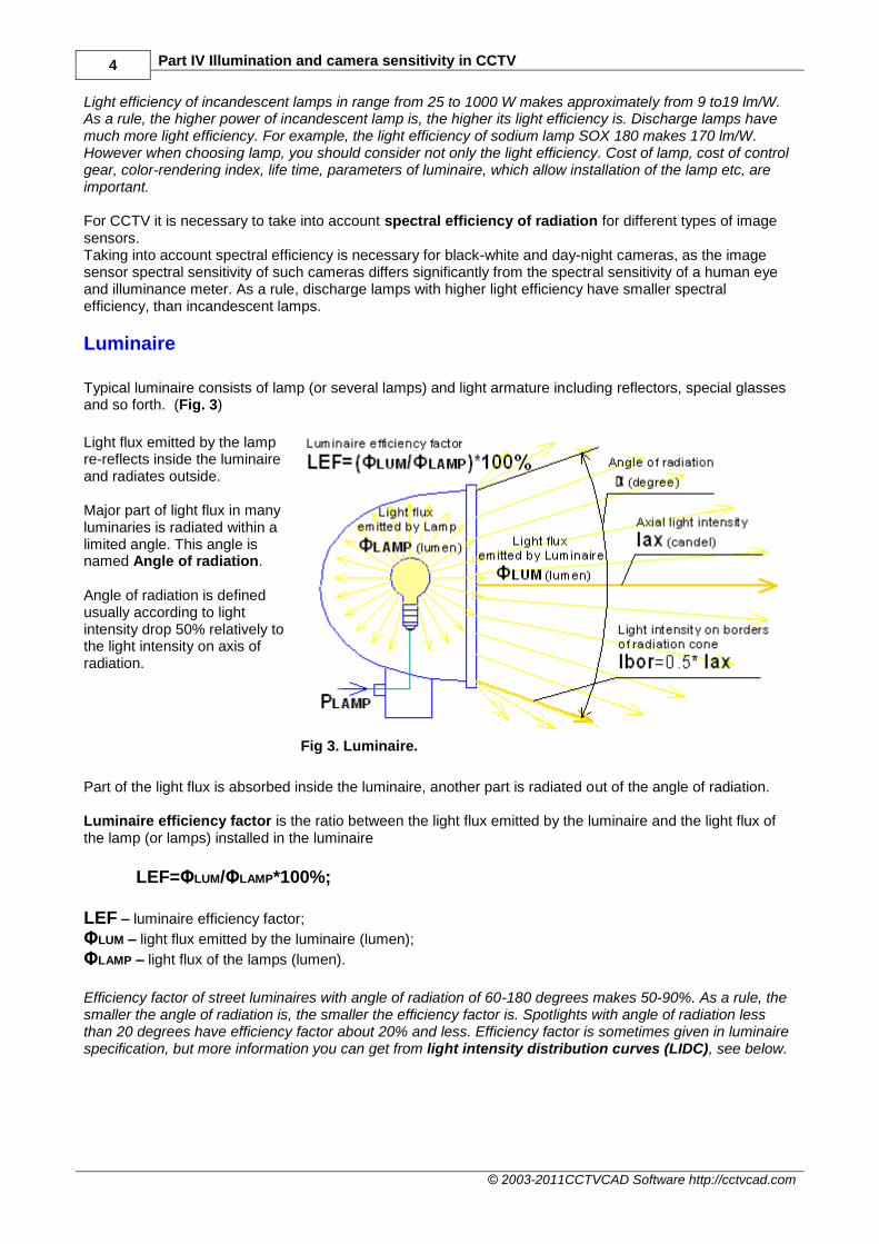
Typical luminaire consists of lamp (or several lamps) and light armature including reflectors, special glasses and so forth. (Fig. 3)
Light flux emitted by the lamp re-reflects inside the luminaire and radiates outside. Major part of light flux in many luminaries is radiated within a limited angle. This angle is named Angle of radiation. Angle of radiation is defined usually according to light intensity drop 50% relatively to the light intensity on axis of radiation.
Fig 3. Luminaire.
Part of the light flux is absorbed inside the luminaire, another part is radiated out of the angle of radiation. Luminaire efficiency factor is the ratio between the light flux emitted by the luminaire and the light flux of the lamp (or lamps) installed in the luminaire
LEF=ΦLUM/ΦLAMP*100%;
LEF – luminaire efficiency factor;
ΦLUM – light flux emitted by the luminaire (lumen);
ΦLAMP – light flux of the lamps (lumen).
Efficiency factor of street luminaires with angle of radiation of 60-180 degrees makes 50-90%. As a rule, the smaller the angle of radiation is, the smaller the efficiency factor is. Spotlights with angle of radiation less than 20 degrees have efficiency factor about 20% and less. Efficiency factor is sometimes given in luminaire specification, but more information you can get from light intensity distribution curves (LIDC), see below.

The principles of CCTV design in VideoCAD 5
© 2003-2011 CCTVCAD Software http://cctvcad.com
Light intensity
Distribution of the light flux of real luminaires in different directions is uneven. Density of the light flux in certain direction is called light intensity.
Light intensity (luminous intensity) is the ratio of light flux of a light source, beamed within the limits of infinitesimal solid angle, to the value of this solid angle. (Fig. 4)
Fig 4. Light intensity. Light intensity is measured in candelas (cd). One candela corresponds to the light flux of one lumen, radiated within the limits of solid angle of one steradian.
I=Φ / Ω;
I – light intensity (candel);
Φ – light flux (lumen) within the limits of solid angle Ω ;
Ω – solid angle (steradian).
Steradian (sr.) – unit of measure of solid angle. Solid angle of one steradian subtends surface on a sphere, the area of which is equal to the squared radius of this sphere (Fig. 5).
Solid angle Ω (steradian), limited by a cone, is
related to the full plane angle β (degrees) at
vertex of this cone by the following formula:
Ω=2 π *(1-cos( β /2) Full plane angle at the vertex of the cone, making 1 steradian, is equal to 65°32'.
Full sphere occupies 4*π steradian.
π=3.14.
Fig 5. Solid angle. For example: Light flux of lamp is equal to 1000 lumen. If the lamp emits with approximately identical intensity in all directions, then average light intensity of the lamp will be equal to 1000/(4*3.14)=80 candel. But if the lamp is installed in luminaire (efficiency factor of the luminaire is 60%) and full light flux is concentrated by the luminaire in solid angle of 1,5 steradian, then the average light intensity within the limits of this angle would be 1000/1,5*0,6=400 candel.

6 Part IV Illumination and camera sensitivity in CCTV
© 2003-2011CCTVCAD Software http://cctvcad.com
Distribution of light intensity within the limits of angle of radiation, as a rule, is uneven. For luminaires with round symmetrical distribution of light flux, as a rule the Axial light intensity is given. It is light intensity on axis of radiation cone. (Fig. 3).
Light intensity distribution curves (LIDC)
Real luminaires have complicated spatial light intensity distribution, which can not be characterized only by the angle of radiation and the axial light intensity. In luminaire specifications there are light intensity distribution curves (LID, LIDC), showing light intensity distribution in dependence on the angle in one or several planes. (Fig. 6)
Fig 6. Light intensity distribution curves (LIDC). Examples. LIDC of some luminaires has rather complex form, but in practical modeling simplifications are allowable. Many luminaires allows installing lamps of different type. That is why LIDC is given for a reference lamp, radiating full light flux of 1000 lumen. For multi-lamp luminaires 1000 lm is total light flux of lamps. In order to get real light intensity in a certain direction, it is needed to divide light intensity in this direction, got from LIDC by 1000, and multiply by the full light flux of the lamps installed in the luminaire. For example: Total light flux of the lamps in luminaire is 3000 lm. In this case the value of light intensity, got from LIDC (with the lamp of 1000 lm) should be multiply by 3. When we know lamp type, we can get light flux of the lamp and take into account spectral efficiency of radiation for different image sensors. Having LIDC of luminaire, we can find out, with what light intensity in what direction this luminaire will radiate. It is possible to calculate illumination, produced by the luminaire at any distance, from the light intensity (see below). Type and light flux of lamp, as well as LIDC of luminaire are important things that we have to know about luminaire.

The principles of CCTV design in VideoCAD 7
© 2003-2011 CCTVCAD Software http://cctvcad.com
Illumination (illuminance)
Camera sensitivity is defined through the minimum scene illumination. In order to connect the luminaire parameters with the camera sensitivity it is needed to determine, which illumination is produced by the luminaire on the scene. Illumination is the density of the light flux, falling on a surface. Illumination is measured in lux (lx).
Average illumination of an area, created by light flux Φ falling on it, is determined by the formula:
E= (Φ/S)*cos(γ);
E– illumination of the area (lux);
Φ – falling light flux (lumen);
S – area (square meter);
γ – angle between normal of the area and light direction (degree). Light flux of 1 lumen, falling perpendicularly to an area of 1 square meter, creates illumination of 1 lux on the area.
Illumination (illuminance) is also measured in foot-candelas (foot-candle, fc, ft-c, lm/ft²). 1 foot-candela equals 10.76 lux. In practice, it is convenient to calculate the direct illumination, created by luminaire from the light intensity of the luminaire.
E= (I/L2)*cos(γ);
E– illumination of the area (lux);
I – light intensity of the luminaire in the direction of the area (candel); L – distance from the luminaire to the area (meter);
γ – angle between normal of the area and light direction (degree).
Illumination depends on angle at which the light flux falls on a surface. Absolutely, light angle influences obtained image. However, the most targets in CCTV are three-dimensional objects, having surfaces placed under different angles.
Light intensity of 1 candela (one lumen per one steradian) creates at distance of 1 meter from the luminaire direct illumination of 1 lux.
Direct illumination of an object, created by luminaire, is proportional to the light intensity of the luminaire in the direction of the object and is inversely as the square of the distance from the luminaire to the object.
(Fig. 7).
Fig 7. Direct illumination, produced by luminaire.

8 Part IV Illumination and camera sensitivity in CCTV
© 2003-2011CCTVCAD Software http://cctvcad.com
The formula is applicable, if the distance up to luminaire is bigger than the size of emitting surface of the luminaire more than in 10 times. Pay attention that the direct illumination, created by luminaire, is inversely as the square of the distance up to the luminaire. Thus, light intensity of 1 candela creates at distance of 10 m from the luminaire illumination, which is equal to 0.01 lux. This is known inverse square law. If the scene is illuminated by several luminaires, the result illumination, created by all luminaires, equals to sum of illuminations, created by each luminaire. In reality scene illumination, created by luminaire, can exceed calculated value of the direct illumination, as the part of light flux re-reflects many times, creating diffused illumination. Diffusion part of light depends on environment, reflection of objects on the scene, their positions and so forth. Indoor diffusion part of light is large, in outdoor installations diffusion part of light is less and depends on the season and weather. Calculation of diffusion component of illumination is an intricate problem and demands big amount of precise source data, which are often unknown at design stage. Real scenes have also some background (ambient) illumination, which is created by sky, street light and other light sources with unknown parameters. We do not know the parameters of these sources, that is why we can not calculate this illumination. We can only measure it using illuminance meter (luxmeter), and then to take it into account at calculations and in modeling. Background illumination is summed up with illumination created by known luminaires. In indoor installations the background illumination also depends on the season and weather. Resulted scene illumination, as a rule, is distributed unevenly. On a scene there are both highlighted and dusky areas. Camera automatics adjust to the average level of illumination. If the contrast between different areas on a scene approaches dynamic range of camera, the highlighted and (or) ducky areas will be clipped.
Reflection
Part of light flux, falling on some object, is absorbed or transmitted through the object, and another part is reflected. Ratio of reflected light flux to the falling light flux is called object reflection factor.
K= Φref/Φf;
K – reflection factor;
Φref – reflected light flux (lumen);
Φf – falling light flux (lumen).
Different objects have different reflection factors, therefore some objects seem to be darker, and other – lighter. Object contrast relatively to the background at equal illumination depends on difference of object and background reflection factors. However in reality object and background illumination can differ. Reflection factor depends on wave length (color) of the falling radiation. Therefore objects look colored, and in infra-red illumination dark and light objects can be swapped. More often reflection from matt surface, so called diffusion reflection, exists in nature. As a result of diffusion reflection, the falling light is reflected with equal intensity in all directions. Further we will consider exactly diffusion reflection. There is also specular reflection from smooth surfaces. Because of the specular reflection on the smooth surfaces there are flares from the light sources.

The principles of CCTV design in VideoCAD 9
© 2003-2011 CCTVCAD Software http://cctvcad.com
Camera
Lens
Part of the light reflected from the scene hits the camera lens. Amount of the light, going through the lens, is determined by lens aperture. The aperture is indicated as F-number. For example: F1.2, F1.4, F2.0… The larger F-number is, the less light goes through the lens. As a rule, the bigger entrance pupil of the lens is, the more light it transmits. Pin-hole lens have the narrowest aperture (larger value of F-number). The aperture of auto iris lenses increases maximally (F-number value decreases) in low light conditions. For such lens instead of aperture, the maximum and minimum apertures are indicated, for example F1.2- F360. Lens optical transmission changes inversely as the square of F-number. For example, the lens F1.0 transmits in 4 times more light, than F2.0.
Camera sensitivity
Camera sensitivity (minimum scene illumination) is a value of the scene illumination (lux) with known reflection factor, at which we can get image with specified acceptable quality. When defining sensitivity for cameras with removable lens, the aperture (F-number) of the lens, with which the indicated sensitivity is assured, should be indicated. Usually these are F1.2, F1.4 or F2.0.
If camera is used with other lens, its sensitivity will be changed inversely as the square of the ratio of the F-number of the lens, installed on the camera, to the F-number of the lens, for which the sensitivity is indicated. For example, camera sensitivity is equal to 0.1 lx with the lens F1.2. Sensitivity of the same camera with the lens F2.0 will make 0.1*(2/1.2)
2=0.28 lx.
Sensitivity depends on exposure time. For standard cameras of PAL system the maximal exposure time is 1/50 sec (PAL) or 1/60 sec (NTSC). For cameras allowing more exposure time, the exposure time, at which indicated sensitivity is obtained, should be obligatory indicated. With practically acceptable accuracy it is possible to consider that sensitivity is inversely to the exposure time (Reciprocity principle).
For example, if camera sensitivity is equal to 0.1 lx at exposure time of 1/5 sec, at exposure time of 1/50 sec the sensitivity of this camera will be 0.1*(1/5)/(1/50)=1 lx. Increased exposure time leads to resolution loss of moving objects. For proper comparison of modern cameras it is necessary to recount sensitivity to the equal exposure time – 1/50 (1/60) sec. Scene reflection factor at determining sensitivity, as a rule, is supposed to be 0.75, as sensitivity measuring is carried out using the test chart printed on white sheet of paper, having approximately the same reflection factor.
Most of real objects have the reflection factor less than 0.75, that is why image quality of real scene at low illumination will be worse than the test chart image (see image models below). Spectral sensitivity of image sensors of black/white and day/night cameras differs from the spectral sensitivity of a human eye and illuminance meter. For such cameras the spectral efficiency of the light source has an importance. Spectral sensitivity of color image sensors is close to the spectral sensitivity of a human eye, therefore influence of spectral efficiency for color cameras is not big.

10 Part IV Illumination and camera sensitivity in CCTV
© 2003-2011CCTVCAD Software http://cctvcad.com
Parameters, limiting image quality at defining sensitivity
Parameters, limiting image quality in low light conditions, for the most cameras are IRE and Signal/noise ratio. In order to understand these parameters let’s have a look at simplified scheme of camera’s work in low light conditions.
Camera’s work in low light conditions
At low illumination electronic shutter set maximum exposure time, aperture is completely opened, therefore electronic shutter and aperture could be not considered. The scheme becomes quite simple. (Fig. 8).
Fig 8. The scheme of camera’s work in low light conditions. Signal from the image sensor, proportional to its illumination, comes to Automatic Gain Control (AGC) scheme. AGC gain is automatically adjusted in order to get optimal image contrast in output.
An Image sensor has always some noise in output. If it is enough illumination, the signal strength significantly exceeds noise level, the AGC gain is low and noise on the image is not visible (Fig. 9). The image was made by the Image analyzer utility in the CCTVCAD Lab Toolkit.
For more information about the utility, see the Help system: Image Analyzer>Signal/noise.
Fig 9. Signal strength significantly exceeds noise level.
Below there is the brightness distribution curve in the selected line.

The principles of CCTV design in VideoCAD 11
© 2003-2011 CCTVCAD Software http://cctvcad.com
When illumination decreases the signal level from the image sensor decreases too and approaches to the noise level. AGC amplifies desired signal together with noises, seeking to keep optimal image contrast (Fig. 10). Thus, at illumination decrease AGC gain increases. As a result, image contrast is not changed, but noise increases.
Fig 10. Signal level from image sensor approaches to the noise level. AGC keeps output image contrast.
However, AGC gain has a limit. At further illumination decrease AGC gain reaches maximum, after what the image contrast begins to decrease – image becomes darker (Fig. 11). At further illumination decrease, noise level practically is not changed. But signal/noise ratio continues diminishing, as image desired signal decreases.
Fig 11. AGC gain is not enough to keep image contrast.

12 Part IV Illumination and camera sensitivity in CCTV
© 2003-2011CCTVCAD Software http://cctvcad.com
Maximum AGC gain of different models of cameras is different. In some cameras image contrast diminishes even before the moment, when noise becomes visible (Fig. 12).
Fig 12. Low Maximum AGC gain.
In other cameras AGC keeps the contrast of very noisy signal (Fig. 13).
Fig. 13. High Maximum AGC gain. For the most of CCTV tasks, the contrast images are more preferable, in spite of disturbing noise. However noisy images have many times bigger size after compression, what decreases the archive depth and the transmission speed across digital communications channels. One more problem is frequent false response of video motion detectors on noise. Some models of cameras have switches, allowing changing the Maximum AGC gain in dependence on application.

The principles of CCTV design in VideoCAD 13
© 2003-2011 CCTVCAD Software http://cctvcad.com
IRE
The parameter IRE came from analog TV, but at present is applied for digital images as well. IRE determines what part of maximum possible brightness range the image occupies. Whole possible brightness range of image is defined as 100IRE. Half of the brightness range corresponds to 50IRE, quarter of the brightness range – 25IRE and etc. Camera sensitivity is usually defined as illumination, at which an output image has 40-50IRE, but there are some exceptions. The bigger IRE value (at the same signal/noise ratio) is indicated in camera sensitivity data, the bigger maximum AGC gain of this camera is, the more contrast (but noisy) image is displayed by the camera at low illumination.
Fig 14. Camera sensitivity 0.1lx at 30IRE, signal/noise ratio 17dB. Illumination 0.1lx.
Fig 15. Camera sensitivity 0.1lx at 80IRE, signal/noise ratio 17dB. Illumination 0.1lx.
Signal/noise ratio
Signal/noise ratio is the ratio of the maximum contrast on image to the root mean square (RMS) value of noise. With practically acceptable accuracy it is possible to consider that AGC operation does not change signal/noise ratio of image. Signal/noise ratio depends only on illumination on the image sensor and its features. Responsible manufacturers usually indicate camera sensitivity as illumination, at which the image has signal/noise ratio equal to 17dB (7 times), 20 dB (10 times) or 24 dB (16 times). Unfortunately, many manufacturers of cameras do not indicate values of signal/noise ratio, which the image will have at indicated minimum scene illumination. Very often as a result of practical measuring camera parameters it becomes evident that at indicated in specification illumination, the image has signal/noise ratio equal to 0dB and less. There is the technique of measuring signal/noise ratio and IRE of digital images in the Help system of CCTVCAD Lab Toolkit software package.

14 Part IV Illumination and camera sensitivity in CCTV
© 2003-2011CCTVCAD Software http://cctvcad.com
On Fig.16, 17 the images, having close IRE values, but different values of signal/noise ratio, are shown.
Fig 16. Camera sensitivity 0.1lx at 50IRE, signal/noise ratio 20dB. Illumination 0.1lx.
Fig 17. Camera sensitivity 0.1lx at 50IRE, signal/noise ratio 7dB. Illumination 0.1lx.
Use of sensitivity in calculations
It is possible to use values of camera sensitivity (lux) in design calculations, if it is known:
Camera parameters, at which specified sensitivity is obtained: o lens aperture (F number); o exposure time (sec).
Parameters of obtained image: o signal/noise ratio (dB); o IRE.
Knowing sensitivity and other parameters, we can model images of different scenes with different illuminations with the help of parametric camera model existing in VideoCAD. This model includes the image formation laws in dependence on illumination. The model takes into account the dynamic range, basic components of noise and spectral sensitivity of image sensor, quantum noise, AGC, brightness, contrast, electronic shutter control, gamma correction, back light compensation (BLC), lens aperture, auto-iris operation. The model is practically tested with many real cameras and shown very good accuracy for practice.

The principles of CCTV design in VideoCAD 15
© 2003-2011 CCTVCAD Software http://cctvcad.com
Image processing inside camera
In modern cameras the obtained image goes through special image processing. As a result of the image processing at low illumination other parameters of the output image are worsened. More often the resolution decreases, as a result of digital noise reduction or combining signals from neighboring pixels. Often a manufacturer of cameras with noise reduction indicates high sensitivity in specification, but writes nothing about the resolution drop. Noise reduction is useful, as it decreases size of noisy images after compression and false response of video motion detectors, but true value of sensitivity should be indicated at switched-off noise reduction. On Fig. 18, 19 there is example of the mistake made in sensitivity valuation, to which the processing can lead. On the left there is image model, obtained at illumination equal to camera sensitivity without processing: 0.1 lx (50IRE, Signal/noise 17dB). On the right there is image from the camera with the same image sensor at illumination of 0.03 lx, but with additional amplification and blurring.
The trick is that measuring noise and IRE of the image on the right gives the same results, that the left image have. This allows manufacturer to indicate camera sensitivity of 0.03 lx (50IRE, Signal/noise 17dB). But compare amount of information on the images. Before processing signal/noise ratio of the right image was 7.8dB.
Fig 18. Illumination 0.1lx, without processing, Image parameters: 50IRE, Signal/noise 17dB.
Fig 19. Illumination 0.03lx, additional amplification and blurring. Image parameters: 50IRE, Signal/noise 17dB.
If we are interested in amount of information on image, the accurate result of measurement can be obtained only at switched-off additional processing. Although image processing inside camera improves image appearance, but does not increase the amount of information on the image, does not allow to see what was absent on the image before processing. Marketing tricks of manufacturers complicate significantly design calculation of illumination in CCTV. Universal and common way to get real parameters of cameras is only practical measuring. For this purpose CCTVCAD Lab Toolkit software package offers special tools and techniques.
16 Part IV Illumination and camera sensitivity in CCTV
© 2003-2011CCTVCAD Software http://cctvcad.com
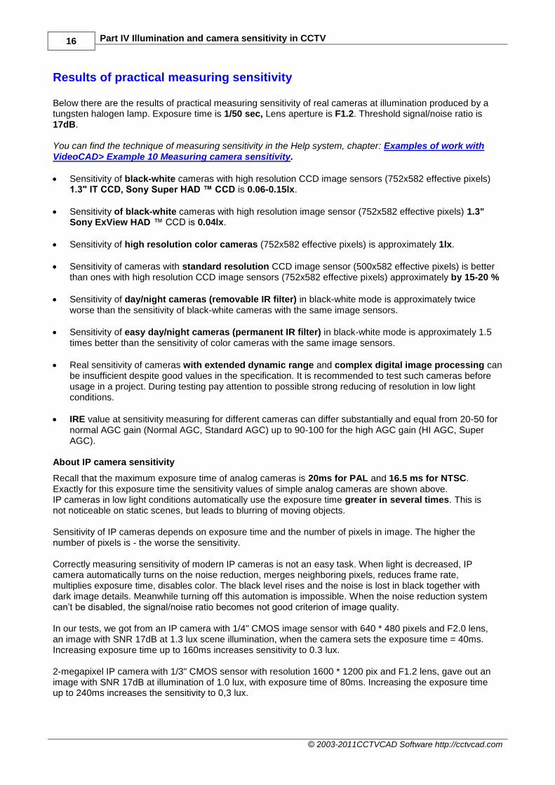
Results of practical measuring sensitivity Below there are the results of practical measuring sensitivity of real cameras at illumination produced by a tungsten halogen lamp. Exposure time is 1/50 sec, Lens aperture is F1.2. Threshold signal/noise ratio is 17dB. You can find the technique of measuring sensitivity in the Help system, chapter: Examples of work with VideoCAD> Example 10 Measuring camera sensitivity.
Sensitivity of black-white cameras with high resolution CCD image sensors (752x582 effective pixels) 1.3" IT CCD, Sony Super HAD ™ CCD is 0.06-0.15lx.
Sensitivity of black-white cameras with high resolution image sensor (752x582 effective pixels) 1.3" Sony ExView HAD ™ CCD is 0.04lx.
Sensitivity of high resolution color cameras (752x582 effective pixels) is approximately 1lx.
Sensitivity of cameras with standard resolution CCD image sensor (500x582 effective pixels) is better than ones with high resolution CCD image sensors (752x582 effective pixels) approximately by 15-20 %
Sensitivity of day/night cameras (removable IR filter) in black-white mode is approximately twice worse than the sensitivity of black-white cameras with the same image sensors.
Sensitivity of easy day/night cameras (permanent IR filter) in black-white mode is approximately 1.5 times better than the sensitivity of color cameras with the same image sensors.
Real sensitivity of cameras with extended dynamic range and complex digital image processing can be insufficient despite good values in the specification. It is recommended to test such cameras before usage in a project. During testing pay attention to possible strong reducing of resolution in low light conditions.
IRE value at sensitivity measuring for different cameras can differ substantially and equal from 20-50 for normal AGC gain (Normal AGC, Standard AGC) up to 90-100 for the high AGC gain (HI AGC, Super AGC).
About IP camera sensitivity
Recall that the maximum exposure time of analog cameras is 20ms for PAL and 16.5 ms for NTSC. Exactly for this exposure time the sensitivity values of simple analog cameras are shown above. IP cameras in low light conditions automatically use the exposure time greater in several times. This is not noticeable on static scenes, but leads to blurring of moving objects. Sensitivity of IP cameras depends on exposure time and the number of pixels in image. The higher the number of pixels is - the worse the sensitivity. Correctly measuring sensitivity of modern IP cameras is not an easy task. When light is decreased, IP camera automatically turns on the noise reduction, merges neighboring pixels, reduces frame rate, multiplies exposure time, disables color. The black level rises and the noise is lost in black together with dark image details. Meanwhile turning off this automation is impossible. When the noise reduction system can’t be disabled, the signal/noise ratio becomes not good criterion of image quality. In our tests, we got from an IP camera with 1/4" CMOS image sensor with 640 * 480 pixels and F2.0 lens, an image with SNR 17dB at 1.3 lux scene illumination, when the camera sets the exposure time = 40ms. Increasing exposure time up to 160ms increases sensitivity to 0.3 lux. 2-megapixel IP camera with 1/3" CMOS sensor with resolution 1600 * 1200 pix and F1.2 lens, gave out an image with SNR 17dB at illumination of 1.0 lux, with exposure time of 80ms. Increasing the exposure time up to 240ms increases the sensitivity to 0,3 lux.

The principles of CCTV design in VideoCAD 17
© 2003-2011 CCTVCAD Software http://cctvcad.com
Work with VideoCAD
Let's try to model a simple example in VideoCAD.
First of all, create new project, place camera on the layout and several 3D models of people at different distances (Fig. 20). For details on how to do this, see the first part Camera view area. Leave geometrical parameters of camera on default. In practical work we will move from the camera to the luminaire.
Fig 20. The scene. Modeling illumination is disabled.
Specifying camera sensitivity
Stored camera models
For specifying sensitivity, it is easier to assign a model with set parameters to the camera. Parameters of camera models in VideoCAD data base have been measured practically. You can insert in the data base models of your cameras after measuring its parameters.
You can find the technique of measuring camera sensitivity in the Help system of CCTVCAD Lab Toolkit software package. For more information about the Table of camera models, see: Interface>Table of camera models. For assigning model to the active camera just select model name in the Model of active camera combo box, on the Tool bar (Fig. 21).
To assign chosen model to several cameras, select desired cameras, and then right click on the Model of active camera combo box and select Assign to selected cameras item. As a result of model assigning camera parameters are set according to the model parameters.
Fig 21. Assigning stored model to the loaded

18 Part IV Illumination and camera sensitivity in CCTV
© 2003-2011CCTVCAD Software http://cctvcad.com
camera.
Sensitivity parameters
It is possible not to assign a model, but to set sensitivity parameters severally. To do this click Sensitivity
and resolution button on the Tool bar. Sensitivity and resolution box will appear (Fig. 24). Resolution parameters are described in the third part of the article 3D Modeling in VideoCAD. If a model has been assigned to the camera, the parameters in this box are set according to the model parameters and are locked. To make the parameters accessible, remove model assignment. You can remove model assignment by selecting=Unassigned=in the Model of loaded camera combo box or by right click on this box and having selected Remove model assignment. (Fig. 22).
Fig 22. Removing model assignment.
Camera
Let’s model real camera with parameters measured beforehand, for example PELCO MC3710H-7X. (Fig. 23).
Fig 23. Camera PELCO MC3710H-7X.
Manufacturer indicates sensitivity of 0.07 lx at 40IRE with the lens F1.2. Signal/noise ratio is not indicated. Maximum exposure time is 1/50s. Black/white camera, with image sensor SONY Super HAD™ CCD. According to the measuring results with the lens F1.2, the sensitivity is equal to 0.07 lx at signal/noise ratio of 17dB and 38IRE. Results of practical measurements comply with specification. Below only basic parameters are described. For more information about these and other parameters, see the Help system: Interface>Sensitivity and resolution.

The principles of CCTV design in VideoCAD 19
© 2003-2011 CCTVCAD Software http://cctvcad.com
First of all choose Color:
b/w - black-white camera;
color - color camera;
day/night - full day/night camera, which has infra-red filter that is mechanically removed in black-white mode;
easy day/night – camera has infra-red filter which is not removed in black-white mode;
Choose b/w. Do not mark ExView check box, as the image sensor SONY ExView HAD™ is not used in this camera. Camera color and ExView parameter are used for assigning color to image model in consideration of spectral sensitivity of the image sensor to light from different sources. VideoCAD takes into account the spectral sensitivity automatically, it is enough to choose correctly light source type and camera color. For more information about the Spectral efficiency, see the Help system: Interface>Sensitivity and resolution>Camera. Specify minimum scene illumination 0.07 lx.
Fig 24. Sensitivity and resolution box. Camera parameters.
You can use the value from the manufacturer’s specification only if you are completely sure. We strongly recommend you to use practical measurement in accordance with the technique in the Help system: Examples of work with VideoCAD> Example 10 Measuring camera sensitivity If there is no possibility of practical measurement, see chapter: Recommendations on the program use>About cameras sensitivity in the Help system.
Specify, at which aperture, signal/noise ratio, IRE and exposure time (ms), the Minimum scene illumination is determined. Select F1.2, 17dB, 38IRE and 20ms. Set Exposure limits of electronic shutter. Select 1/50 – 1/100000 sec. Clear Fix. check box on the AGC panel, if the box is marked . Maximum AGC gain will be calculated inside the program from other parameters. If the maximum AGC gain is indicated in the camera parameters, it can be specified explicitly in the Maximum box. Set the degree of gamma-correction – 0.45.

20 Part IV Illumination and camera sensitivity in CCTV
© 2003-2011CCTVCAD Software http://cctvcad.com
Lens
Let’s assume that the lens with fixed iris and F2.0 aperture is installed on our camera.
Mark the Fixed Iris box. Select F2.0 in the Maximum Aperture combo box on the left (Fig. 25). If the lens aperture can be changed, select minimum and maximum aperture values in the Aperture limits combo boxes.
Fig 25. Sensitivity and resolution box. Lens parameters.
In case of using lens with manual iris, it is needed to select Manual Iris. After that, it is possible to change current value of the aperture in specified limits. In case of using Auto Iris lens, it is needed to select Auto Iris. In this case the current aperture will be calculated during modeling. Electronic shutter (AESC) will be disabled. It is possible to select type of Auto Iris. In case of Video Drive lens, the adjustments Level and ALC become available as on the real lenses.
Sensitivity parameters have been assigned. Close the Sensitivity and resolution box by clicking the top right corner of the box and agree to save changes.
The principles of CCTV design in VideoCAD 21
© 2003-2011 CCTVCAD Software http://cctvcad.com
Scene
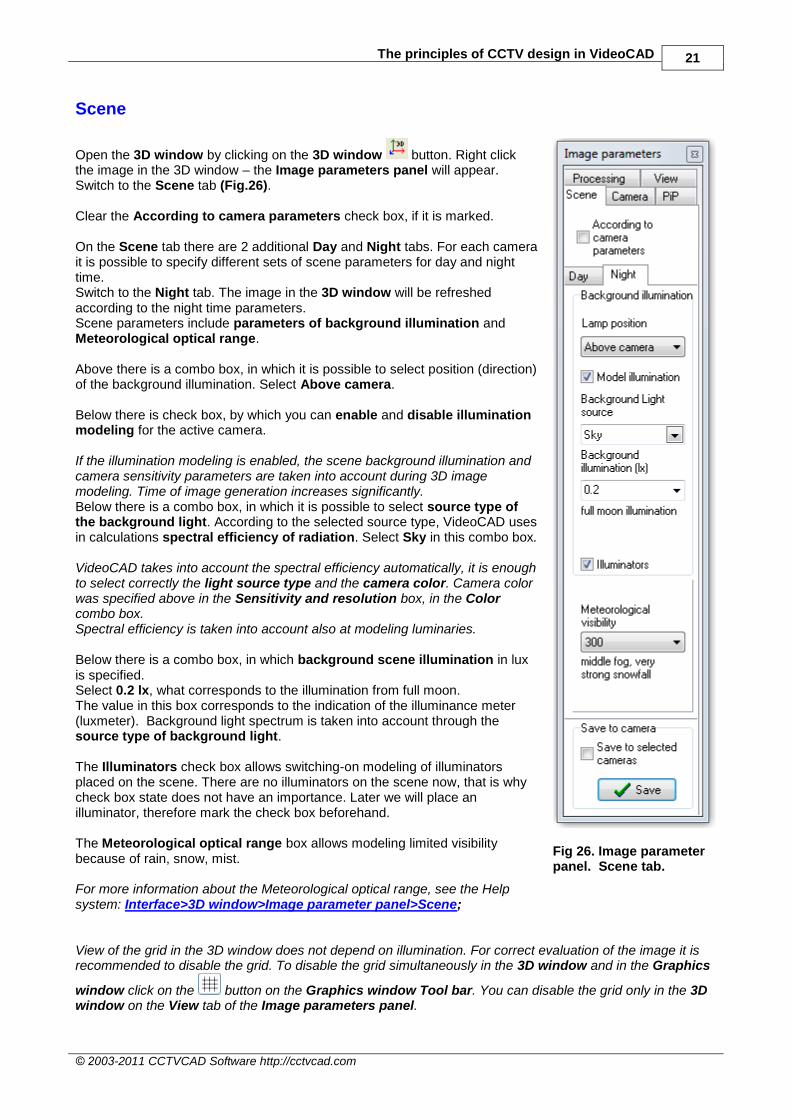
Open the 3D window by clicking on the 3D window button. Right click the image in the 3D window – the Image parameters panel will appear. Switch to the Scene tab (Fig.26). Clear the According to camera parameters check box, if it is marked. On the Scene tab there are 2 additional Day and Night tabs. For each camera it is possible to specify different sets of scene parameters for day and night time. Switch to the Night tab. The image in the 3D window will be refreshed according to the night time parameters. Scene parameters include parameters of background illumination and Meteorological optical range. Above there is a combo box, in which it is possible to select position (direction) of the background illumination. Select Above camera. Below there is check box, by which you can enable and disable illumination modeling for the active camera. If the illumination modeling is enabled, the scene background illumination and camera sensitivity parameters are taken into account during 3D image modeling. Time of image generation increases significantly. Below there is a combo box, in which it is possible to select source type of the background light. According to the selected source type, VideoCAD uses in calculations spectral efficiency of radiation. Select Sky in this combo box. VideoCAD takes into account the spectral efficiency automatically, it is enough to select correctly the light source type and the camera color. Camera color was specified above in the Sensitivity and resolution box, in the Color combo box. Spectral efficiency is taken into account also at modeling luminaries. Below there is a combo box, in which background scene illumination in lux is specified. Select 0.2 lx, what corresponds to the illumination from full moon. The value in this box corresponds to the indication of the illuminance meter (luxmeter). Background light spectrum is taken into account through the source type of background light. The Illuminators check box allows switching-on modeling of illuminators placed on the scene. There are no illuminators on the scene now, that is why check box state does not have an importance. Later we will place an illuminator, therefore mark the check box beforehand. The Meteorological optical range box allows modeling limited visibility because of rain, snow, mist. For more information about the Meteorological optical range, see the Help system: Interface>3D window>Image parameter panel>Scene;
Fig 26. Image parameter panel. Scene tab.
View of the grid in the 3D window does not depend on illumination. For correct evaluation of the image it is recommended to disable the grid. To disable the grid simultaneously in the 3D window and in the Graphics
window click on the button on the Graphics window Tool bar. You can disable the grid only in the 3D window on the View tab of the Image parameters panel.

22 Part IV Illumination and camera sensitivity in CCTV
© 2003-2011CCTVCAD Software http://cctvcad.com
Scene image model at background illumination
After specifying all parameters, we will see in the 3D window an image model from the camera with the lens F2.0 at specified scene illumination of 0.2 lx (Fig. 27).
Fig 27. Image model from the camera with the lens F2.0 at scene illumination of 0.2 lx.
Try to change parameters of background illumination on the Scene tab, in order to see how they influence the image. Then open the Sensitivity and resolution box and replace the lens F2.0 to more high-aperture one, F0.8. As a result the image will be changed (Fig. 28). Give back the parameters to the values set before and return to the image on the Fig. 27.
Fig 28. Image model from the camera with the lens F0.8 at scene illumination of 0.2 lx.

The principles of CCTV design in VideoCAD 23
© 2003-2011 CCTVCAD Software http://cctvcad.com
Luminaire
Luminaire parameters
Place on the scene the real model of luminaire: OSRAM LUM HALOSTAR
® 1000 (Fig. 29).
Fig 29. Picture and the Light intensity distribution curves (LIDC) of the OSRAM LUM HALOSTAR® 1000
It is followed from the LIDC, that light intensity distribution is not round-symmetric. Horizontal angle is larger than the vertical one. VideoCAD allows accurate modeling by one illuminator model only round-symmetric light intensity distribution. Complex distributions can be modeled by several illuminators, or you can accept simplifications in dependence of the problem features. Simplifications are allowed in practice. From the LIDC we can determine the angles of radiation (full double angles) according to the light intensity drop by 50% (Fig. 29): Horizontally – 73 degrees; Vertically – 41 degrees; Average angle – (73+41)/2=57 degrees. Let’s determine Axial light intensity of the luminaire. From the LIDC follows that axial light intensity is 750 candel with lamp with light flux of 1000 lm. The halogen lamp OSRAM HALOLINE
® 1000 Watt is installed in
the luminaire. Full light flux of the lamp is 22000 lm. Thus, axial light intensity of this luminaire with the lamp OSRAM HALOLINE
® 1000 Watt will make
750cd/1000lm*22000lm=16500 cd. At simplifying the model it is necessary to keep calculated light intensity.

24 Part IV Illumination and camera sensitivity in CCTV
© 2003-2011CCTVCAD Software http://cctvcad.com
Modeling luminaire
Create an illuminator. To do this click Illuminator button on the Tool bar. The Illuminator calculation box will appear. In the box it is needed to specify known parameters of the luminaire (Fig. 30).
Fig 30. Illuminator calculation box.
The box is divided in 2 panels. On the left panel there are lamp parameters, on the right panel – luminaire parameters. You should start specifying parameters from the top left corner. After specifying lamp parameters, it is needed to specify luminaire parameters on the right panel of the box also from the top to the bottom. First of all it is needed to choose lamp type used in the luminaire. On the basis of chosen lamp type, VideoCAD uses in calculation averaged light efficiency of this lamp type and spectral efficiency of radiation for different types of image sensors. In the Lamp type combo box it is possible to select IR LED (InfraRed Light Emitting Diode) of known wavelength for IR illuminator modeling. For more information about modeling infra-red illuminator, see the Help system: Interface> Illuminator calculation >IR illuminators.
Select halogen incandescent lamp. Below there are grey boxes, which are not accessible by default, in which averaged light efficiency and spectral efficiency factor for the chosen lamp type are indicated. It is not recommended to change these factors without necessity.

The principles of CCTV design in VideoCAD 25
© 2003-2011 CCTVCAD Software http://cctvcad.com
For more information about the Spectral efficiency, see the Help system: Interface>Illuminator calculation>Lamp; Examples of work with VideoCAD>Example 16 Determining spectral efficiency of light source.
After specifying the lamp type, it is needed to specify its power in watt, in the Lamp power combo box. In our luminaire the lamp of 1000 Watt power is used.
On the right, in the Light flux emitted by lamp box the calculated value of full light flux of the lamp will appear. This value is based on an averaged light efficiency of the chosen lamp type. Calculated value is 17000 lm. Light efficiency depends on the lamp power. In our luminaire the high-power lamp with efficiency bigger than averaged efficiency of halogen lamps is used. That is why, we should correct full light flux to the value from the lamp specification – 22000 lm.
The lamp parameters have been specified, move to the right panel of the box and specify luminaire parameters. First of all specify number of lamps in the luminaire in the Lamp quantity box. In the luminaire one lamp is installed.
Efficiency factor is not given in the luminaire specification. For the luminaire with average angle of radiation of 57 degrees specify efficiency factor=0.5 preliminary. See recommendations how to choose the efficiency factor in the Help system: Interface>Illuminator calculation>Luminaire; On the right in the Light flux emitted by illuminator (lm) box the calculated full light flux of the illuminator – 11000 lumen will be displayed. Then we have to choose, whether this illuminator is an omnidirectional light source, i.e. distributes the light flux with approximately identical intensity in all directions, or is it a projector with a limited angle of radiation. Choose: projector. Specify angle of radiation (full double angle at the top of the light cone). As VideoCAD allows accurate modeling luminaires only with round-symmetric light intensity distribution, it is necessary to accept a simplification: for modeling axial light intensity insert average angle obtained from LIDC (see above) = 57 degrees. If we need to model precise horizontal angle of radiation, we should specify in the Angle of radiation box the horizontal angle determined from LIDC, - 73 degrees. And then by selection of Concentration value and Efficiency factor, obtain value of axial light intensity close to the given in specification one (16500 cd). Below there is the Concentration box, in which it is possible to specify light intensity distribution inside the cone limited by the angle of radiation. Value in this box corresponds to the ratio of light intensity on boarders of the radiation cone to the light intensity on axis of the radiation cone (axial light intensity). Specify in this box 0.5, what corresponds to light intensity drop on boarders of the radiation cone by 50%. View of the light intensity distribution curve will be displayed in the Graphics window after creating illuminator, if the illuminator is selected. (Fig. 31).
Fig 31. View of the Light intensity distribution of selected illuminator in the Graphics window.

26 Part IV Illumination and camera sensitivity in CCTV
© 2003-2011CCTVCAD Software http://cctvcad.com
Below the calculated value of the axial light intensity – 19900 cd is displayed. Obtained value differs to some extent from LIDC (16500 cd), as we accepted simplifications. Correct the Efficiency factor to 0.4 and obtain 15900 cd. The value is close to the LIDC. All illuminator parameters have been specified. Below, on the Illumination at distance panel there are boxes, using which it is possible to calculate illumination created by this luminaire on axis of radiation at specified distance. The calculation is not obligatory and can be carried out for information. Having specified the distance in the Distance box, we will see calculated illumination at this distance in the Illumination box.
Click OK.
Specify by clicking illuminator position in the horizontal projection behind the camera at the distance of 100 meters from camera. Then by second click specify the direction of axis of radiation to the camera and objects (Fig. 32).
Fig 32. Illuminator position.
Specify Illuminator height above the ground (2 m) and inclination angle (0 degrees) on the Current construction parameter panel (Fig. 33)
Fig 33. Specifying inclination angle and height above the ground.
Make third click on any place. By the third click it is possible to change the angle of radiation graphically. To do this, clear the Ang box on Current construction parameter panel. But in most cases it is not recommended to change the angle of radiation specified before. The luminaire model in 3D space has been created. Illumination of any object within the area, illuminated by the luminaire model, will be modeled in VideoCAD. For editing the created illuminator double click on its icon on the layout. To call the Illuminator calculation
box click the Illuminator calculation button on the appeared Current construction parameter panel. On the Current construction parameter panel it is possible to switch on and off the illuminator, to specify a diffused part of light for approximate calculation of reflected light. It is possible to switch type of the illuminator to the virtual one. Virtual illuminators are used for modeling unequal illumination distribution on the scene or distant light sources, parameters of which are unknown and only illumination created by them is known.
For more information about Illuminator parameters on the Current construction parameter panel, see the Help system: Interface>Graphics window>Pop-up panels>Current construction parameter panel>Illuminator.
To create several identical illuminators copy the existing one.

The principles of CCTV design in VideoCAD 27
© 2003-2011 CCTVCAD Software http://cctvcad.com
Selected illuminators can be switched on and off simultaneously with the help of pop-up menu appeared by right clicking on the layout. Switching on and off illuminators is applied only to the active camera. You should switch on and off required illuminators for each camera separately. No more than 7 illuminators can be switched on for each camera. See also the Help system: Examples of work with VideoCAD>Example 14 Examples of luminaire calculation.
Scene image model with the luminaire switched on
Open the 3D window by click on the 3D
window button. Right click on the image in the 3D window, the Image parameter panel will appear (Fig. 26). Switch to the Scene tab. Clear the According to camera parameters box, if it is marked. On the Scene tab switch to the Night tab. Mark the Model illumination and Illuminators boxes. In the 3D window you will see the image model (Fig. 34).
Fig 34. Image model at background illumination of 0.2lx + illumination from the luminaire placed at 100 m behind the camera.
Try to place the illuminator next to the camera. Illumination unevenness on the scene will become too big, there will be clipped areas on the image (Fig. 35).
From this example it becomes evident that the evenness of scene illumination is important. Position of high-power illuminators next to cameras is an unsuccessful decision in many cases.
Fig 35. Image model at background illumination of 0.2lx + illumination from the luminaire placed next to the camera.

28 Part IV Illumination and camera sensitivity in CCTV
© 2003-2011CCTVCAD Software http://cctvcad.com
Maintenance factors
Luminaire efficiency factors and camera sensitivity can differ from the specification data. Light flux of luminaires depends on supply voltage, which can be unstable. Luminaire and camera parameters degrade during operation. That is why in real projects it is necessary to create a reserve in dependence on environment pollution and maintenance schedule, according to the CIE 97 standard.
For more information about the Maintenance factors, see the Help system: Interface>Option box>3D modeling.

The principles of CCTV design in VideoCAD 29
© 2003-2011 CCTVCAD Software http://cctvcad.com
Practical advices
First of all it is necessary to determine if additional illumination is needed. To take this decision it is needed to measure illumination on the site using illuminance meter (luxmeter), and then model measured illumination as the background one and obtain image models from models of used cameras in the project.
Illumination should be measured in the worst conditions: cloudy autumn night. As a target for modeling use contrast and low-contrast 3D models.
If image quality is not satisfactory, first of all, try to use more sensitive models of cameras or high-aperture lens for obtaining desired quality. Illumination measuring and choice of camera models should be carried out for each camera separately. Thus, it is possible to make reasonable choice of camera and lens models.
See also the Help system: Examples of work with VideoCAD> Example 9 Choice of camera model according to known scene illumination.
If it is not possible to obtain images of desired quality, then additional illumination is required.
Above it was mentioned, that scene illumination includes:
background (ambient) illumination produced by sky, street light and other light sources;
direct illumination from light sources with known parameters;
diffused illumination, produced by the re-reflected light from surrounding objects
There is a lot of diffused light in enclosed spaces. In open spaces the diffused part of light is much smaller and we can ignore it. Diffused light in this case will be an additional reserve in calculations. In VideoCAD we can calculate rather precisely and model direct illumination from light sources with known parameters. We can not calculate background and diffused illumination, but we can measure it practically, and then model it in VideoCAD.
Illumination with taken into account diffused light could be approximately calculated by means of techniques of lighting engineering or with the help of specialized lighting software, for example DIALux. It is necessary to remember, that background and diffused illumination can vary widely, they depend on season, weather, properties and positions of surrounding objects. Background illumination depends also on condition of remote light sources.
Let’s consider some practical cases:
At the surveillance site, there is a system of artificial illumination and its modernization is not planned. The problem of designing video surveillance system taking into account illumination consists in camera choice and their positioning. In this case it is enough to measure scene illumination for each camera and model it in VideoCAD as background illumination. For modeling illumination unevenness, modeling positions and parameters of existing light sources can be required. Virtual illuminators can be used for modeling big illumination differences.
Surveillance site is an open space. It is necessary to design video surveillance system and artificial illumination. Diffused part of light in open space is small. We can use models of luminaires in VideoCAD for the complex design of the video surveillance system. If it is allowed to take into account background illumination, it is necessary to measure it separately for each camera. VideoCAD is suitable for solving such problems.
Surveillance site is an enclosed space. It is necessary to design video surveillance system and illumination system. This is more complicated problem, for solving which many data will be required. It is recommended to use additional lighting software for illumination calculation. Using results of the illumination calculation by the lighting software reduce the problem to the first case.
Back:
Part I. Camera view area. Part II. Person detection area, person identification area, license plate reading area. Spatial resolution. Part III. 3D modeling in VideoCAD. Continue:
Part V. Video surveillance of moving objects.