the progress of survey techniques in underwater sites: the
TRANSCRIPT
THE PROGRESS OF SURVEY TECHNIQUES IN UNDERWATER SITES:
THE CASE STUDY OF CAPE STOBA SHIPWRECK
E. Costa
Ca’ Foscari University of Venice, Dorsoduro 3484/D, 30123 Venezia, Italy
Iuav University of Venice, Santa Croce 191, 30125 Venezia ([email protected])
Commission II – WGII/9
KEY WORDS: Cultural Heritage, Underwater Archaeology, Survey technique, Photogrammetry, 3D Modelling
ABSTRACT:
The experience on a 10-11th century AD cargo of amphoras of the shipwreck of Cape Stoba, in the island of Mljet, in Croatia could
be considered an important example to describe the progress of documentation and survey on a shipwreck. In the first part of the paper, we describe some of the used feasible methods of documentation and their advantages and disadvantages. In the second part,
we introduce the three-dimensional reconstruction of the items recovered during the archaeological excavation and how these elements could be integrated to the different types of documentation: bi-dimensional plans, three-dimensional coordinates and multi-
image photogrammetry. 3D reconstruction allows to decrease and optimize time and work during the excavation and to obtain a complete range of data for post-excavation study, permitting to better document, represent and investigate the position of the cargo. Furthermore, 3D modelling offers an attractive display for the public, who can better appreciate cultural heritage and archaeological evidence.
1. INTRODUCTION Documentation and survey of archaeological sites, both underwater and terrestrial, have gone through an evident and
clear change in the last two decades (Balletti et al., 2016).
Reviewing the evolution of the surveying techniques, three-
dimensional surveys and representations of shipwrecks or
cargos are very useful in order to better evaluate the volume and
the arrangement of a cargo. The 3D documentation allows a
better perception of the site, above all in difficult contexts
where the archaeological subject is not on the same level or is teeming with details. A simple plan with depths marked on it
does not highlight the real appearance of a shipwreck (Drap et
al., 2003; Green, 2004). Underwater, for hyperbaric reasons, diving time is limited by
depth and in deep sites, it is more reduced than in shallow water: for example around 40 m, diving time is only 18 minutes
and around 28 m it is extended to 35 minutes. In these contexts,
the survey and documentation activities have to be fast and
precise. The arrangement of accurate documentation, in
particular for stratigraphic excavations, is a peculiar and
important aspect related to underwater archaeology. Every
archaeological site and every different study require a specific
technology; first, archaeologists have to analyze the object and
the context of excavation, then they have to know the economic possibility and the project timing. After this kind of evaluation
it is possible to understand the appropriate recording technology
and the appropriate representation and format of the results
(Gonizzi et al., 2014). In this paper, we present and evaluate some of the surveying
techniques applied on the same underwater shipwreck during different seasons of excavation. The experience and test filed
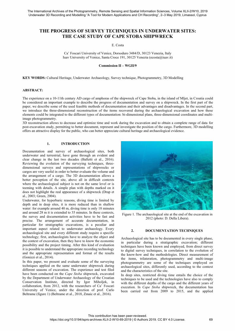
have been conducted on the Cape Stoba shipwreck, excavated by the Department of Underwater Archaeology of the Croatian
Conservation Institute, directed by Igor Miholjek, in collaboration, from 2012, with the researchers of Ca’ Foscari
University of Venice, under the direction of prof. Carlo Beltrame (figure 1) (Beltrame et al., 2018, Zmaic et al., 2016).
Figure 1. The archaeological site at the end of the excavation in
2012 (photo: D. Della Libera).
2. DOCUMENTATION TECHNIQUES Archaeological site has to be documented in every single phase, in particular during a stratigraphic excavation; different
techniques have been known and employed, from direct survey to digital survey techniques, in correlation to the evolution of
the know-how and the methodologies. Direct measurement of
the items, trilateration, photogrammetry and multi-image
photogrammetry are some of the techniques employed on archaeological sites, differently used, according to the context
and the characteristics of the site. In deep sites, restricted diving time entails the choice of the techniques to be used and the technologies have also to comply with the different depths of the cargo and the different years of execution. In Cape Stoba shipwreck, the documentation has been carried out from 2009 to 2015, and the applied
The International Archives of the Photogrammetry, Remote Sensing and Spatial Information Sciences, Volume XLII-2/W10, 2019 Underwater 3D Recording and Modelling “A Tool for Modern Applications and CH Recording”, 2–3 May 2019, Limassol, Cyprus
This contribution has been peer-reviewed. https://doi.org/10.5194/isprs-archives-XLII-2-W10-69-2019 | © Authors 2019. CC BY 4.0 License.
69
technologies have gone through an impressive development from the first to the last year. In the firsts three years, the researchers have used a trilateration to document the position of the amphoras of the cargo. In 2012,
we have applied an analogic photogrammetric survey and in 2015 we have used the multi-image photogrammetry and the
Structure from Motion technique. At the end of the mission, the obtained data (plan and 3D model) have been compared and
integrated to achieve a complete survey of the cargo of the shipwreck. The documentation has oriented in the same
reference system thanks to a topographic survey realized by some control points on the site. These mainly belong to the legs
of the grid used for the trilateration during the first three years survey, that have remained still for all the campaigns.
2.1 Direct survey: trilateration Direct measurement and trilateration are simple methods to
document a site, usually employed since the beginning of
underwater archaeology, both in shallow and deep water
(Balletti et al., 2015; Green, 2004). This easy and economic technique needs a meter tape or a double meter stick, but it
requires a long time of fulfillment and it has a suitable precision
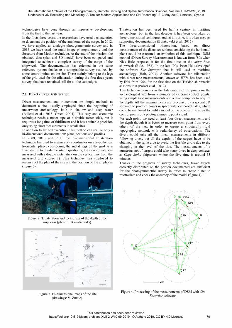
only using short measurements in small sites. In addition to limited execution, this method can realize only a bi-dimensional documentation: plans, sections and profiles. In 2009, 2010 and 2011 the bi-dimensional trilateration
technique has used to measure xy coordinates on a hypothetical horizontal plane, considering the metal legs of the grid as a
fixed datum to divide the site in quadrants; the z coordinate was measured with a double meter stick on the vertical line from the
measured grid (figure 2). This technique was employed to reconstruct the plan of the site and the position of the amphoras
(figure 3).
Figure 2. Trilateration and measuring of the depth of the amphoras (photo: J. Kwiatkowski).
Figure 3. Bi-dimensional maps of the site (drawings: V. Zmaic).
Trilateration has been used for half a century in maritime
archaeology, but in the last decades it has been overtaken by three-dimensional techniques and, at this time, it is often used as supporting documentation (Bojakowski et al., 2015). The three-dimensional trilateration, based on direct
measurement of the distances without considering the horizontal
plane could be esteemed an evolution of this technique. DSM
method (Direct Survey Measurement) is known from ’80s when
Nick Rule proposed it for the first time on the Mary Rose
shipwreck (Rule, 1982). In the late ’90s, Peter Holt developed
the software Site Surveyor that is still used in maritime archaeology (Holt, 2003). Another software for trilateration
with direct tape measurements, known as WEB, has been used
by INA from ’90s, for the first time on the Turkish shipwrecks
as Bozburun (Polzer et al., 2012). This technique consists in the trilateration of the points on the
archaeological site from a number of external control points, using simple tape measurements and a dive computer to acquire
the depth. All the measurements are processed by a special 3D software to produce points in space with xyz coordinates, which
could be employed to build a model of the objects or to align the
control points of a photogrammetric point cloud. For each point, we need at least four direct measurements and
the depth though it is better to measure each point from every others of the net, in order to create a structurally rigid
topographic network with redundancy of observations. The divers could take all the linear measurements in different
following dives, but all the depths of the targets have to be obtained in the same dive to avoid the feasible errors due to the
changing in the level of the tide. The measurements of a numerous net of targets could take many dives in deep contexts
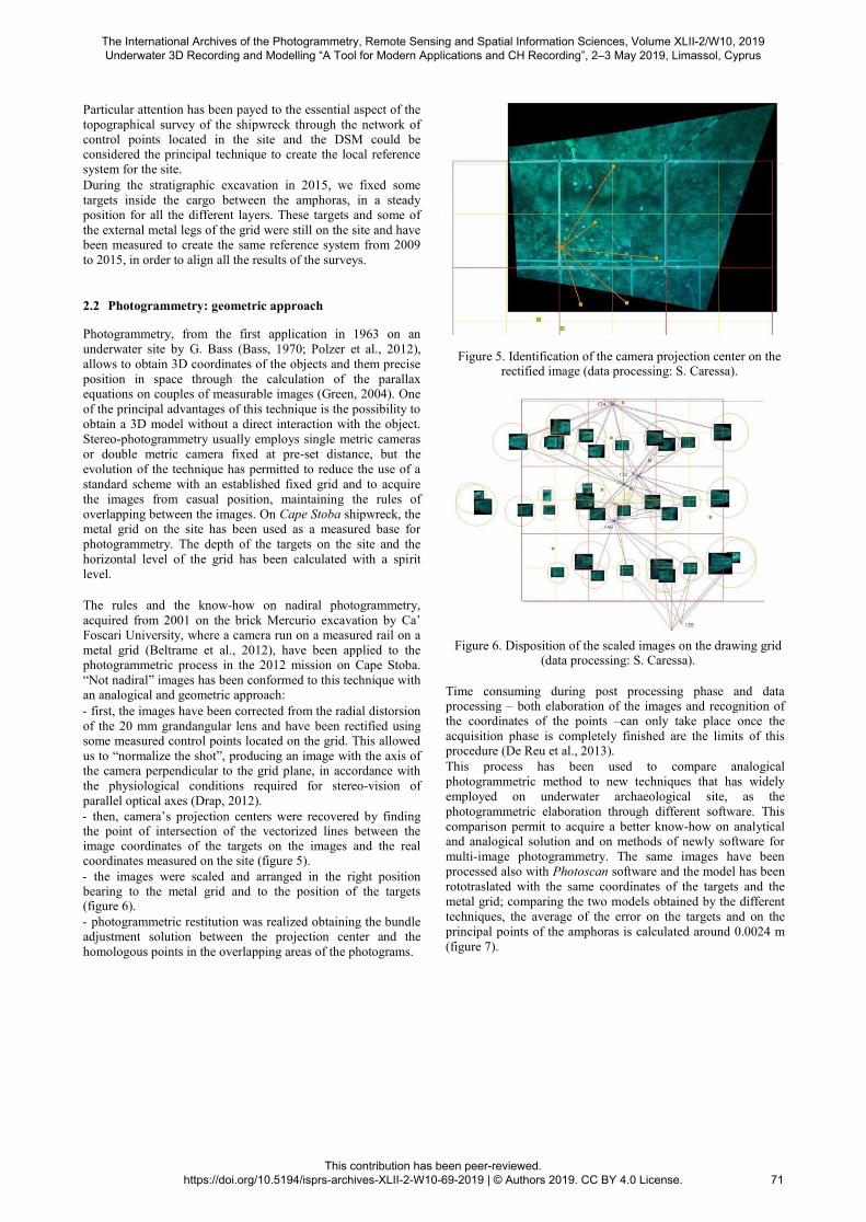
as Cape Stoba shipwreck where the dive time is around 35 minutes. Thanks to the progress of survey techniques, fewer targets correctly distributed on the portion documented are sufficient for the photogrammetric survey in order to create a net to rototraslate and check the accuracy of the model (figure 4).
Figure 4. Processing of the measurements of DSM with Site Recorder software.
The International Archives of the Photogrammetry, Remote Sensing and Spatial Information Sciences, Volume XLII-2/W10, 2019 Underwater 3D Recording and Modelling “A Tool for Modern Applications and CH Recording”, 2–3 May 2019, Limassol, Cyprus
This contribution has been peer-reviewed. https://doi.org/10.5194/isprs-archives-XLII-2-W10-69-2019 | © Authors 2019. CC BY 4.0 License.
70
Particular attention has been payed to the essential aspect of the
topographical survey of the shipwreck through the network of control points located in the site and the DSM could be considered the principal technique to create the local reference system for the site. During the stratigraphic excavation in 2015, we fixed some
targets inside the cargo between the amphoras, in a steady position for all the different layers. These targets and some of
the external metal legs of the grid were still on the site and have been measured to create the same reference system from 2009
to 2015, in order to align all the results of the surveys.
2.2 Photogrammetry: geometric approach Photogrammetry, from the first application in 1963 on an
underwater site by G. Bass (Bass, 1970; Polzer et al., 2012),
allows to obtain 3D coordinates of the objects and them precise
position in space through the calculation of the parallax equations on couples of measurable images (Green, 2004). One
of the principal advantages of this technique is the possibility to
obtain a 3D model without a direct interaction with the object.
Stereo-photogrammetry usually employs single metric cameras
or double metric camera fixed at pre-set distance, but the
evolution of the technique has permitted to reduce the use of a
standard scheme with an established fixed grid and to acquire
the images from casual position, maintaining the rules of
overlapping between the images. On Cape Stoba shipwreck, the metal grid on the site has been used as a measured base for
photogrammetry. The depth of the targets on the site and the
horizontal level of the grid has been calculated with a spirit
level.
The rules and the know-how on nadiral photogrammetry,
acquired from 2001 on the brick Mercurio excavation by Ca’ Foscari University, where a camera run on a measured rail on a
metal grid (Beltrame et al., 2012), have been applied to the photogrammetric process in the 2012 mission on Cape Stoba.
“Not nadiral” images has been conformed to this technique with an analogical and geometric approach: - first, the images have been corrected from the radial distorsion
of the 20 mm grandangular lens and have been rectified using some measured control points located on the grid. This allowed
us to “normalize the shot”, producing an image with the axis of the camera perpendicular to the grid plane, in accordance with
the physiological conditions required for stereo-vision of
parallel optical axes (Drap, 2012). - then, camera’s projection centers were recovered by finding the point of intersection of the vectorized lines between the image coordinates of the targets on the images and the real coordinates measured on the site (figure 5). - the images were scaled and arranged in the right position bearing to the metal grid and to the position of the targets (figure 6). - photogrammetric restitution was realized obtaining the bundle adjustment solution between the projection center and the
homologous points in the overlapping areas of the photograms.
Figure 5. Identification of the camera projection center on the rectified image (data processing: S. Caressa).
Figure 6. Disposition of the scaled images on the drawing grid (data processing: S. Caressa).
Time consuming during post processing phase and data processing – both elaboration of the images and recognition of the coordinates of the points –can only take place once the
acquisition phase is completely finished are the limits of this procedure (De Reu et al., 2013). This process has been used to compare analogical
photogrammetric method to new techniques that has widely
employed on underwater archaeological site, as the
photogrammetric elaboration through different software. This
comparison permit to acquire a better know-how on analytical and analogical solution and on methods of newly software for
multi-image photogrammetry. The same images have been
processed also with Photoscan software and the model has been
rototraslated with the same coordinates of the targets and the
metal grid; comparing the two models obtained by the different
techniques, the average of the error on the targets and on the
principal points of the amphoras is calculated around 0.0024 m
(figure 7).
The International Archives of the Photogrammetry, Remote Sensing and Spatial Information Sciences, Volume XLII-2/W10, 2019 Underwater 3D Recording and Modelling “A Tool for Modern Applications and CH Recording”, 2–3 May 2019, Limassol, Cyprus
This contribution has been peer-reviewed. https://doi.org/10.5194/isprs-archives-XLII-2-W10-69-2019 | © Authors 2019. CC BY 4.0 License.
71
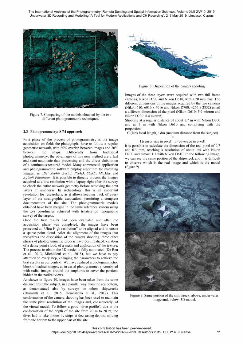
Figure 7. Comparing of the models obtained by the two different photogrammetric techniques.
2.3 Photogrammetry: SfM approach First phase of the process of photogrammetry is the image acquisition on field; the photographs have to follow a regular
geometric network, with 60% overlap between images and 20%
between the strips. Differently from traditional
photogrammetry, the advantages of this new method are a fast
and semi-automatic data processing and the direct elaboration
of a continuous textured model. Many commercial application
and photogrammetric software employ algorithm for matching
images, as 3DF Zephir Aerial, Pix4D, SURE, MicMac and
Agisoft Photoscan. It is possible to directly process the images acquired at a low resolution with a laptop right after the survey
to check the entire network geometry before removing the next
layers of amphoras. In archaeology, this is an important
revolution for researchers, as it allows keeping track of every
layer of the stratigraphic excavation, permitting a complete
documentation of the site. The photogrammetric models
obtained have been merged in the same reference system using
the xyz coordinates achieved with trilateration topographic survey of the targets. Once the first results had been evaluated and after the
acquisition phase was completed, the images have been processed at “Ultra High resolution” to be aligned and to create
a sparse point cloud. After the alignment of the images that recognizes the disposition of the camera shooting, three other
phases of photogrammetric process have been realized: creation of a dense point cloud, of a mesh and application of the texture.
The process to obtain the 3D model is fully automated (De Reu et al., 2013, Michieletti et al., 2015), but we have to pay
attention to every step, changing the parameters to achieve the best results in our context. We have realized a photogrammetric
block of nadiral images, as in aerial photogrammetry, combined with radial images around the amphoras to cover the portions
hidden in the nadiral views. As shown in figure 10, images have been taken from the same
distance from the subject, in a parallel way from the sea bottom,
as demonstrated also by surveys on others shipwrecks
(Diamanti et al., 2015, Demesticha et al., 2012). This
conformation of the camera shooting has been used to maintain
the same pixel resolution of the images and, consequently, of
the virtual model. To follow a good “dive-profile”, due to the
conformation of the depth of the site from 20 m to 28 m, the
diver had to take photos by strips at decreasing depths, moving
from the bottom to the upper part of the site.
Figure 8. Disposition of the camera shooting.
Images of the three layers were acquired with two full frame
cameras, Nikon D700 and Nikon D610, with a 20 mm lens. The different dimensions of the images acquired by the two cameras
(Nikon 610: 6016 x 4016 and Nikon D700: 4256 x 2832) entail a different dimension of the pixel (Nikon D610: 5.9 micron and
Nikon D700: 8.4 micron). Shooting at a regular distance of about 1.7 m with Nikon D700 and at 1 m with Nikon D610 and complying with the proportion:
C (lens focal length) : dm (medium distance from the subject)
= l (sensor size in pixel): L (coverage in pixel)
it is possible to calculate the dimension of the real pixel of 0.7
and 0.3 mm, reaching a resolution of about 1:4 with Nikon
D700 and almost 1:1 with Nikon D610. In the following image,
we can see the same portion of the shipwreck and it is difficult
to observe which is the real image and which is the model
(figure 9).
Figure 9. Same portion of the shipwreck: above, underwater image and, below, 3D model.
The International Archives of the Photogrammetry, Remote Sensing and Spatial Information Sciences, Volume XLII-2/W10, 2019 Underwater 3D Recording and Modelling “A Tool for Modern Applications and CH Recording”, 2–3 May 2019, Limassol, Cyprus
This contribution has been peer-reviewed. https://doi.org/10.5194/isprs-archives-XLII-2-W10-69-2019 | © Authors 2019. CC BY 4.0 License.
72
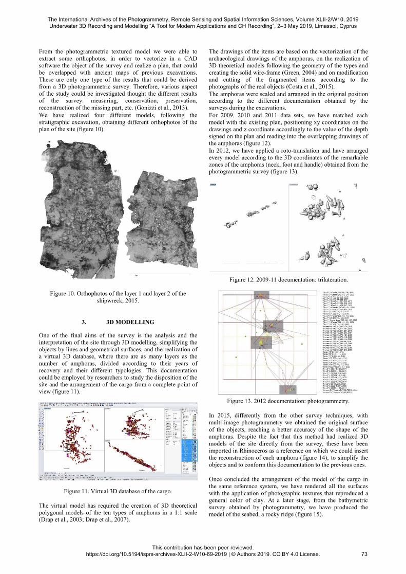
From the photogrammetric textured model we were able to
extract some orthophotos, in order to vectorize in a CAD software the object of the survey and realize a plan, that could
be overlapped with ancient maps of previous excavations.
These are only one type of the results that could be derived from a 3D photogrammetric survey. Therefore, various aspect
of the study could be investigated thought the different results of the survey: measuring, conservation, preservation,
reconstruction of the missing part, etc. (Gonizzi et al., 2013). We have realized four different models, following the stratigraphic excavation, obtaining different orthophotos of the plan of the site (figure 10).
The drawings of the items are based on the vectorization of the
archaeological drawings of the amphoras, on the realization of 3D theoretical models following the geometry of the types and
creating the solid wire-frame (Green, 2004) and on modification
and cutting of the fragmented items according to the photographs of the real objects (Costa et al., 2015). The amphoras were scaled and arranged in the original position according to the different documentation obtained by the surveys during the excavations. For 2009, 2010 and 2011 data sets, we have matched each model with the existing plan, positioning xy coordinates on the
drawings and z coordinate accordingly to the value of the depth signed on the plan and reading into the overlapping drawings of the amphoras (figure 12). In 2012, we have applied a roto-translation and have arranged every model according to the 3D coordinates of the remarkable zones of the amphoras (neck, foot and handle) obtained from the photogrammetric survey (figure 13).
Figure 10. Orthophotos of the layer 1 and layer 2 of the shipwreck, 2015.
3. 3D MODELLING One of the final aims of the survey is the analysis and the interpretation of the site through 3D modelling, simplifying the
objects by lines and geometrical surfaces, and the realization of a virtual 3D database, where there are as many layers as the
number of amphoras, divided according to their years of recovery and their different typologies. This documentation
could be employed by researchers to study the disposition of the site and the arrangement of the cargo from a complete point of
view (figure 11).
Figure 11. Virtual 3D database of the cargo.
The virtual model has required the creation of 3D theoretical polygonal models of the ten types of amphoras in a 1:1 scale (Drap et al., 2003; Drap et al., 2007).
Figure 12. 2009-11 documentation: trilateration.
Figure 13. 2012 documentation: photogrammetry.
In 2015, differently from the other survey techniques, with
multi-image photogrammetry we obtained the original surface
of the objects, reaching a better accuracy of the shape of the
amphoras. Despite the fact that this method had realized 3D
models of the site directly from the survey, these have been
imported in Rhinoceros as a reference on which we could insert the reconstruction of each amphora (figure 14), to simplify the
objects and to conform this documentation to the previous ones.
Once concluded the arrangement of the model of the cargo in the same reference system, we have rendered all the surfaces
with the application of photographic textures that reproduced a general color of clay. At a later stage, from the bathymetric
survey obtained by photogrammetry, we have produced the model of the seabed, a rocky ridge (figure 15).
The International Archives of the Photogrammetry, Remote Sensing and Spatial Information Sciences, Volume XLII-2/W10, 2019 Underwater 3D Recording and Modelling “A Tool for Modern Applications and CH Recording”, 2–3 May 2019, Limassol, Cyprus
This contribution has been peer-reviewed. https://doi.org/10.5194/isprs-archives-XLII-2-W10-69-2019 | © Authors 2019. CC BY 4.0 License.
73
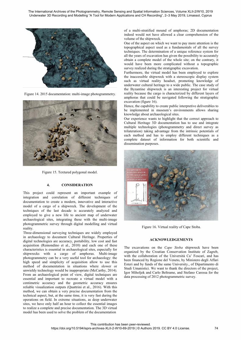
Figure 14. 2015 documentation: multi-image photogrammetry.
Figure 15. Textured polygonal model.
4. CONSIDERATION This project could represent an important example of
integration and correlation of different techniques of
documentation to create a modern, innovative and interactive
model of a cargo of a shipwreck. The development of the
techniques of the last decade is accurately analyzed and
employed to give a new life to ancient map of underwater
archaeological sites, integrating these with the multi-image
photogrammetric survey through digital modelling and virtual
reality. Three-dimensional surveying techniques are widely employed
in archaeology to document Cultural Heritage. Properties of
digital technologies are accuracy, portability, low cost and fast acquisition (Remondino et al., 2010) and each one of these
characteristics is essential in archaeological sites, especially for
shipwrecks with a cargo of amphoras. Multi-image
photogrammetry can be a very useful tool for archaeology: the
high speed and simplicity of acquisition allow to use this
method of documentation in situations where slower or
unwieldy technology would be inappropriate (McCarthy, 2014).
From an archaeological point of view, digital techniques are essential and important to recreate a virtual model with a
centimetric accuracy and the geometric accuracy ensures
reliable visualization outputs (Quattrini et al., 2016). With this
method, we can obtain a very precise documentation from the
technical aspect, but, at the same time, it is very fast during the
operations on field. In extreme situations, as deep underwater
sites, we have only half an hour to collect the essential images
to realize a complete and precise documentation. The 3D virtual
model has been used to solve the problem of the documentation
of a multi-stratified mound of amphoras; 2D documentation indeed would not have allowed a clear comprehension of the volume of the shipwreck. One of the aspect on which we want to pay more attention is the topographical aspect used as a fundamentals of all the survey
techniques. The determination of a unique reference system for all the years of excavation has given the possibility to accurately
obtain a complete model of the whole site; on the contrary, it would have been more complicated without a topographic
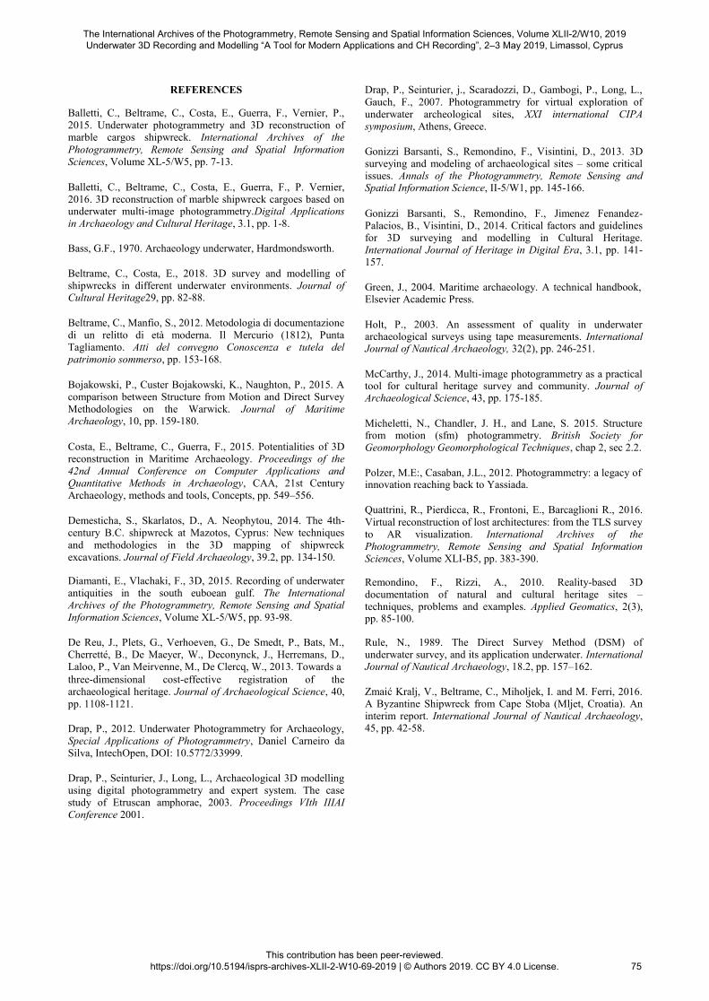
survey realized during the stratigraphic excavation. Furthermore, the virtual model has been employed to explore
the inaccessible shipwreck with a stereoscopic display system such as virtual reality headset, promoting knowledge of
underwater cultural heritage to a wide public. The case study of the Byzantine shipwreck is an interesting project for virtual
reality because the cargo is characterized by different layers of amphoras that could be navigated following the stratigraphic
excavation (figure 16). Hence, the capability to create public interpretive deliverables to be implemented in museum’s environments allows sharing knowledge about archaeological sites. Our experience wants to highlight that the correct approach to Cultural Heritage 3D documentation has to use and integrate
multiple technologies (photogrammetry and direct survey as trilateration) taking advantage from the intrinsic potentials of
each method and has to employ different techniques as a complete dataset of information for both scientific and
dissemination purposes.
Figure 16. Virtual reality of Cape Stoba.
ACKNOWLEDGEMENTS The excavations on the Cape Stoba shipwreck have been
organized by the Croatian Conservation Institute of Zagreb,
with the collaboration of the Università Ca’ Foscari, and has been financed by Regione del Veneto, by Ministero degli Affari
Esteri and by funds of the same University., of Dipartimento di Studi Umanistici. We want to thank the directors of the project,
Igor Miholjek and Carlo Beltrame, and Stefano Caressa for the data processing of 2012 photogrammetric survey.
The International Archives of the Photogrammetry, Remote Sensing and Spatial Information Sciences, Volume XLII-2/W10, 2019 Underwater 3D Recording and Modelling “A Tool for Modern Applications and CH Recording”, 2–3 May 2019, Limassol, Cyprus
This contribution has been peer-reviewed. https://doi.org/10.5194/isprs-archives-XLII-2-W10-69-2019 | © Authors 2019. CC BY 4.0 License.
74
REFERENCES Balletti, C., Beltrame, C., Costa, E., Guerra, F., Vernier, P., 2015. Underwater photogrammetry and 3D reconstruction of marble cargos shipwreck. International Archives of the
Photogrammetry, Remote Sensing and Spatial Information Sciences, Volume XL-5/W5, pp. 7-13.
Balletti, C., Beltrame, C., Costa, E., Guerra, F., P. Vernier, 2016. 3D reconstruction of marble shipwreck cargoes based on underwater multi-image photogrammetry.Digital Applications in Archaeology and Cultural Heritage, 3.1, pp. 1-8.
Bass, G.F., 1970. Archaeology underwater, Hardmondsworth.
Beltrame, C., Costa, E., 2018. 3D survey and modelling of shipwrecks in different underwater environments. Journal of Cultural Heritage29, pp. 82-88.
Beltrame, C., Manfio, S., 2012. Metodologia di documentazione
di un relitto di età moderna. Il Mercurio (1812), Punta Tagliamento. Atti del convegno Conoscenza e tutela del patrimonio sommerso, pp. 153-168.
Bojakowski, P., Custer Bojakowski, K., Naughton, P., 2015. A comparison between Structure from Motion and Direct Survey Methodologies on the Warwick. Journal of Maritime Archaeology, 10, pp. 159-180.
Costa, E., Beltrame, C., Guerra, F., 2015. Potentialities of 3D reconstruction in Maritime Archaeology. Proceedings of the 42nd Annual Conference on Computer Applications and Quantitative Methods in Archaeology, CAA, 21st Century Archaeology, methods and tools, Concepts, pp. 549–556.
Demesticha, S., Skarlatos, D., A. Neophytou, 2014. The 4th-century B.C. shipwreck at Mazotos, Cyprus: New techniques
and methodologies in the 3D mapping of shipwreck excavations. Journal of Field Archaeology, 39.2, pp. 134-150. Diamanti, E., Vlachaki, F., 3D, 2015. Recording of underwater antiquities in the south euboean gulf. The International Archives of the Photogrammetry, Remote Sensing and Spatial Information Sciences, Volume XL-5/W5, pp. 93-98.
De Reu, J., Plets, G., Verhoeven, G., De Smedt, P., Bats, M., Cherretté, B., De Maeyer, W., Deconynck, J., Herremans, D., Laloo, P., Van Meirvenne, M., De Clercq, W., 2013. Towards a three-dimensional cost-effective registration of the archaeological heritage. Journal of Archaeological Science, 40,
pp. 1108-1121.
Drap, P., 2012. Underwater Photogrammetry for Archaeology, Special Applications of Photogrammetry, Daniel Carneiro da Silva, IntechOpen, DOI: 10.5772/33999.
Drap, P., Seinturier, J., Long, L., Archaeological 3D modelling using digital photogrammetry and expert system. The case study of Etruscan amphorae, 2003. Proceedings VIth IIIAI Conference 2001.
Drap, P., Seinturier, j., Scaradozzi, D., Gambogi, P., Long, L.,
Gauch, F., 2007. Photogrammetry for virtual exploration of underwater archeological sites, XXI international CIPA symposium, Athens, Greece.
Gonizzi Barsanti, S., Remondino, F., Visintini, D., 2013. 3D surveying and modeling of archaeological sites – some critical issues. Annals of the Photogrammetry, Remote Sensing and Spatial Information Science, II-5/W1, pp. 145-166.
Gonizzi Barsanti, S., Remondino, F., Jimenez Fenandez-Palacios, B., Visintini, D., 2014. Critical factors and guidelines for 3D surveying and modelling in Cultural Heritage. International Journal of Heritage in Digital Era, 3.1, pp. 141-157.
Green, J., 2004. Maritime archaeology. A technical handbook, Elsevier Academic Press.
Holt, P., 2003. An assessment of quality in underwater archaeological surveys using tape measurements. International Journal of Nautical Archaeology, 32(2), pp. 246-251.
McCarthy, J., 2014. Multi-image photogrammetry as a practical tool for cultural heritage survey and community. Journal of Archaeological Science, 43, pp. 175-185.
Micheletti, N., Chandler, J. H., and Lane, S. 2015. Structure from motion (sfm) photogrammetry. British Society for Geomorphology Geomorphological Techniques, chap 2, sec 2.2.
Polzer, M.E:, Casaban, J.L., 2012. Photogrammetry: a legacy of innovation reaching back to Yassiada.
Quattrini, R., Pierdicca, R., Frontoni, E., Barcaglioni R., 2016.
Virtual reconstruction of lost architectures: from the TLS survey to AR visualization. International Archives of the Photogrammetry, Remote Sensing and Spatial Information Sciences, Volume XLI-B5, pp. 383-390. Remondino, F., Rizzi, A., 2010. Reality-based 3D documentation of natural and cultural heritage sites – techniques, problems and examples. Applied Geomatics, 2(3), pp. 85-100. Rule, N., 1989. The Direct Survey Method (DSM) of underwater survey, and its application underwater. International Journal of Nautical Archaeology, 18.2, pp. 157–162.
Zmaić Kralj, V., Beltrame, C., Miholjek, I. and M. Ferri, 2016. A Byzantine Shipwreck from Cape Stoba (Mljet, Croatia). An interim report. International Journal of Nautical Archaeology, 45, pp. 42-58.
The International Archives of the Photogrammetry, Remote Sensing and Spatial Information Sciences, Volume XLII-2/W10, 2019 Underwater 3D Recording and Modelling “A Tool for Modern Applications and CH Recording”, 2–3 May 2019, Limassol, Cyprus
This contribution has been peer-reviewed. https://doi.org/10.5194/isprs-archives-XLII-2-W10-69-2019 | © Authors 2019. CC BY 4.0 License.
75