the proteus umx 310 wireless bridge for video surveillance ... · the proteus umx 310 is used in...
TRANSCRIPT

The Proteus UMX 310 Wireless Bridge For Video Surveillance Applications
Application Note July 2015

Proteus UMX 310 Application Note
2
Abstract. This application note describes Microwave Networks’ Proteus UMX 310 point-to-point and point-to-multipoint wireless bridge in the 4.9 GHz and 5.8 GHz bands and its application in mission critical and industrial video, SCADA, VoIP, and TDM services.
Table of Contents
Page
Proteus UMX 310 Overview 3
Proteus UMX 310 Description 4
RF Interference Mitigation in License Exempt Bands 6
Network Management 8
Cybersecurity 9
Application Bandwidth Considerations 9
Conclusion 12
About Microwave Networks 13
Copyright © 2015 Microwave Networks, Inc.
Microwave Networks, Inc. 4000 Greenbriar Dr. Stafford, TX 77477
1-281-263-6500
www.microwavenetworks.com

Proteus UMX 310 Application Note
3
The Proteus UMX 310 Wireless Bridge
For Video Surveillance Applications
Overview
Available in FCC 4.9 GHz (public safety), and license exempt 5.8 GHz (UNII) bands, the Proteus UMX 310 is a wireless Ethernet bridge that offers throughput up to 310 Mbps, low latency, superior RF interference mitigation, and full control and monitoring of its network elements. The Proteus UMX 310 is used in point-to-point (PTP) and point-to-multipoint (PMPT) government and industrial applications. It is well suited for mission critical video, and can also support SCADA, VoIP, and TDM traffic. It can be integrated with the Proteus CyberShield, an industrial grade Gigabit switch with enhanced physical and logical cybersecurity features.
Since mission critical and industrial video applications are bandwidth intensive compared to SCADA, VoIP, or access control systems, the UMX 310 is ideal for wirelessly backhauling video in a variety of sectors:
• Public Safety • Municipalities – Safe Cities • Utilities • Energy – Oil and Gas • Critical Infrastructure • Intelligent Transportation Systems • Education
Example Block Diagram of Proteus UMX 310 Network
SU= subscriber unit. MU=master unit. NMS=network management system
Proteus UMX 310 Application Note
4
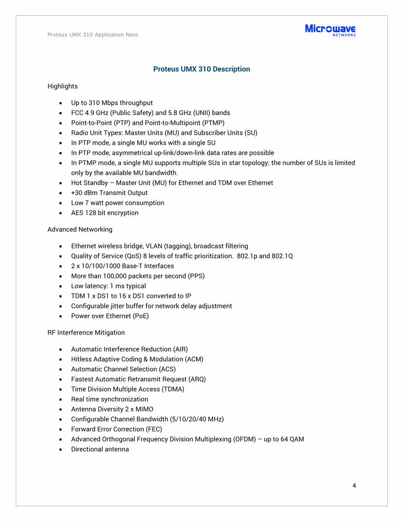
Proteus UMX 310 Description
Highlights
• Up to 310 Mbps throughput • FCC 4.9 GHz (Public Safety) and 5.8 GHz (UNII) bands • Point-to-Point (PTP) and Point-to-Multipoint (PTMP) • Radio Unit Types: Master Units (MU) and Subscriber Units (SU) • In PTP mode, a single MU works with a single SU • In PTP mode, asymmetrical up-link/down-link data rates are possible • In PTMP mode, a single MU supports multiple SUs in star topology; the number of SUs is limited
only by the available MU bandwidth. • Hot Standby – Master Unit (MU) for Ethernet and TDM over Ethernet • +30 dBm Transmit Output • Low 7 watt power consumption • AES 128 bit encryption
Advanced Networking
• Ethernet wireless bridge, VLAN (tagging), broadcast filtering • Quality of Service (QoS) 8 levels of traffic prioritization. 802.1p and 802.1Q • 2 x 10/100/1000 Base-T Interfaces • More than 100,000 packets per second (PPS) • Low latency: 1 ms typical • TDM 1 x DS1 to 16 x DS1 converted to IP • Configurable jitter buffer for network delay adjustment • Power over Ethernet (PoE)
RF Interference Mitigation
• Automatic Interference Reduction (AIR) • Hitless Adaptive Coding & Modulation (ACM) • Automatic Channel Selection (ACS) • Fastest Automatic Retransmit Request (ARQ) • Time Division Multiple Access (TDMA) • Real time synchronization • Antenna Diversity 2 x MIMO • Configurable Channel Bandwidth (5/10/20/40 MHz) • Forward Error Correction (FEC) • Advanced Orthogonal Frequency Division Multiplexing (OFDM) – up to 64 QAM • Directional antenna

Proteus UMX 310 Application Note
5
Master Unit Sector Antenna
60, 90, 120 degrees
Subscriber Unit with Standard Gain (23 dBi) or High Gain (27 dBi) Integrated
Antenna
Outdoor Unit with external TNC connectors
for single or dual polarized antennas
TDM Extender - Internal Unit
1 to 16 T1/E1, built-in QoS with 8 priority queues
The UMX Proteus 310 provides best-in-class 310 Mbps aggregate throughput, ideal for bandwidth intensive video applications. It operates in the FCC 4.9 GHz public safety band (4.940 to 4.990 GHz) and upper 5.8 GHz UNII band (5.730 to 5.845 GHz). Per FCC rules, the 4.9 GHz band offers 18 channels, while the 5.8 GHz band offers up to 24, depending on channel bandwidth configuration.
The UMX features two types of radios: a master unit (MU) and a subscriber unit (SU). In a point-to-point (PTP) topology, the basic system consists of one master unit (MU) and one subscriber unit (SU). In the PTP mode, the system can operate in either symmetrical or asymmetrical mode. The radio is able to dynamically adjust the data rate in each direction across the radio hop, allowing it to handle asymmetric traffic when traffic across the hop is higher in one direction than in the other direction. In a point-to-multipoint topology (PMPT), the basic system consists of one master unit (MU) and several subscriber units (SU) using a Time Division Multiple Access (TDMA) carrier scheme to ensure predictable latency and prevent jitter. Several MUs can be co-located to support dense network designs. MUs can be synchronized to ensure all co-located MUs transmit at the same time to avoid the possibility of one unit transmitting while other units are receiving. Over a large network radios can be synchronized via GPS receivers.

Proteus UMX 310 Application Note
6
A UMX radio unit only consumes 7 watts, making it ideal for green energy power sources such as solar panels or wind energy. Radio units can operate up to +30 dBm transmit output. The UMX also features Automatic Transmit Power Control (ATPC) to reduce the likelihood of interfering with other radios and to reduce power consumption. Using an optional Indoor Unit (IDU), MUs can be configured with redundant hot standby hardware protection, supporting mission critical operations with high availability of essential devices.
The Proteus UMX can operate as a wireless Ethernet bridge, or as a wireless switch to provide a virtual local area network (VLAN). Based on 802.1Q protocol, VLAN frames are tagged and untagged to segment and separate VLANs, such as a video VLAN from a SCADA VLAN or a management VLAN. With advanced networking features, its Quality of Service (QoS) offers eight levels of traffic prioritization, at the MAC level, based on 802.1p protocol. Latency and jitter sensitive services, such as real time streaming video and VoIP telephony, are easily supported. Also the UMX’s configurable jitter buffer adjusts for network delays, ensuring controlled data delivery needed for video and VoIP. The UMX can deliver more than 100,000 packets per second (PPS) with low latency of 1 ms. It also supports up to 16 x DS1 signaling using the optional IDU to support TDM legacy devices by converting TDM data to IP data. Time sensitive TDM traffic can be prioritized with the 802.1p QoS feature. Interfaces are 2 x 10/100/1000 Base-T. For security and confidentiality, the UMX can encrypt traffic utilizing the AES 128 bit standard.
RF Interference Mitigation Techniques in License Exempt Bands
The UMX 310 provides robust RF interference mitigation to enable high throughput and low latency. It is designed with numerous specific interference mitigation features to work in the congested radio frequency (RF) environments of the unlicensed bands. RF interference in license exempt spectrum can affect link quality causing delay and increased packet jitter. The UMX 310 offers 11 features to mitigate interference and uphold link quality, the combination of which makes the UMX 310 unique and best-in-class.
Automatic Interference Reduction (AIR) maintains consistent throughput and low latency by immediately discarding physical signals and frames that do not belong to the system, in other words noise. Using this unique UMX technology, deployments in congested areas show several fold better performance in throughput and latency than competitors.
Hitless Adaptive Coding & Modulation (ACM) ensures error free data transmission, by adapting the data rate to current interference conditions. Adaptive coding and modulation allows the sub-carrier’s modulation to be dynamically varied from QPSK to 64-QAM with varying levels of Forward Error Correction (FEC) based on current transmission conditions. FEC coding and modulation automatically and dynamically adjust in response to packet error rates (PER), ensuring best link quality and throughput. Hitless means no data loss.

Proteus UMX 310 Application Note
7
Automatic Channel Selection (ACS) allows the radio to select the best RF channel by automatically scanning through the band using the built-in RF analyzer to find channels with the least interference.
Fastest Automatic Retransmit Request (ARQ) retransmits lost or corrupted frames ensuring reception of uncorrupted data. Fastest ARQ performed at the physical layer helps ensure low 1 ms latency, achieving best in class performance. Low latency is required for real time streaming video, control of PTZ cameras, and VoIP telephony.
Time Division Multiple Access (TDMA) is a channel access method that schedules and delivers data payloads per defined time slots over a shared link, allowing the delivery of carrier grade or high quality throughput and predictable low latency.
Real time synchronization using internal MU clocks and GPS allows co-location of an unlimited number of wireless master units (MU) on the same mast or co-located masts, eliminating collision interference of data payloads amongst the units. This allows dense sector deployments in star topologies by preventing data collision interference of multiple co-located MUs.
Synchronized Co-Located Master Units
Time synchronization eliminates payload collisions
2 x 2 MIMO (multiple input multiple output) Antenna Diversity connects antennas with vertical and horizontal polarization to the same wireless unit, enabling the transmission and reception of two simultaneous data streams. Using both the vertical and horizontal polarity of dual polarity antennas effectively provides two paths across the hop. When the diversity mode is ‘on’, redundant data is

Proteus UMX 310 Application Note
8
transmitted over both paths. If one path suffers from multipath interference causing data signal corruption, the receiver on the second path can recover data without loss. When the diversity mode is ‘off’, the two channel paths can transmit different data to double throughput. The radio engineer can select either diversity mode or set the radio to operate in automatic mode. In automatic mode, diversity is dynamic and adjusts to actual link conditions: if receive sensitivity (RSSI) difference between MIMO paths is higher than 10 dB, diversity mode is ‘on’ but if the RSSI difference is lower than 10 dB, diversity mode is ‘off’. Configurable Channel Bandwidth allows radio engineers to configure channel bandwidth to match throughput requirements and optimize path robustness. Channel bandwidth configurations are 5 MHz, 10 MHz, 20 MHz, and 40 MHz. Wider channels have higher throughput, but narrower channels are more resistant to interference. Channel bandwidth can be configured independently in the uplink and downlink directions. The radio engineer can select the bandwidth based on throughput requirements and RF channel interference conditions.
Forward Error Correction (FEC) reduces retransmissions caused by correcting corrupted packets. The technique adds redundant data to each packet, which is analyzed for errors upon reception. When errors are detected, the FEC technique uses the redundant data to recover the original packet avoiding the need for retransmission.
Advanced Orthogonal Frequency Division Multiplexing (OFDM) waveform is optimized for high bandwidth and low latency applications in challenging RF environments. OFDM is a frequency-division multiplexing scheme used as a digital multi-carrier modulation method. OFDM splits data into sub signals transmitting them simultaneously over different frequencies within its band. The receiver collects sub signals and reassembles the original data. Redundancy in the OFDM signal allows lost or corrupted data to be recovered. The UMX 310 features up to 64 QAM - quadrature amplitude modulation of the OFDM signals. OFDM offers high interference resiliency and low latency.
Directional Antennas focus the RF signal into a narrow beam concentrating the power compared to an omni-directional antenna. In addition to reducing RF interference, directional antennas increase the practical path length. Long paths of 60 miles or more can be achieved for lower throughput requirements.
When all 11 RF mitigation features are combined, the UMX 310 is the most powerful radio system for fighting interference in the 4.9 and 5.8 GHz bands. It is ideal for intensive bandwidth applications such as video and shared services including SCADA, VoIP, access control, and TDM legacy circuits.
Network Management
The UMX management tools include WEB management, element manger (EMS), Telnet, and SNMP network management. With over-the-air (OTA) management, the network administrator can easily configure PTMP or PTP topologies, monitor and configure MU and SU radios, shape and prioritize traffic, monitor performance at a glance, and analyze logs to troubleshoot or optimize network performance.

Proteus UMX 310 Application Note
9
Microwave Networks’ secured WEB management provides advanced capabilities and powerful analytics for configuration, control, and monitoring of Proteus UMX units. The Proteus UMX WEB interface is managed from any computer, operating system, tablets, and smartphones. The WEB network management system provides complete control of a network of UMX radios from a single location, providing operational management and monitoring with centralized administration. Administrators can monitor, configure radios and networking, log activity, analyze traffic, and analyze the spectrum. Network managers can utilize the UMX’s built-in RF analyzer as a predictive site survey tool to assist in the placement and alignment of radio units; they can monitor the RF spectrum and adjust path parameters in response to the RF environment.
RF Analyzer (WEB Management)
Cybersecurity
The UMX 310 and its devices can be integrated with the Proteus CyberShield, an industrial grade Gigabit switch/router with enhanced physical and logical cybersecurity features. CyberShield can support microwave, video, SCADA, or access control devices, ensuring network integrity, availability, and confidentiality for critical infrastructure operations. It also features power over Ethernet (PoE) to power remote devices such as IP video cameras. For more information about CyberShield, please ask your Microwave Networks director or refer to CyberShield product information.
Application Bandwidth Considerations
Security grade video surveillance is a cost effective way to provide safety and security of human and physical assets. Industrial or mission critical video systems typically operate 24 hours days and 7 days a week. IP network cameras are becoming increasingly popular replacing legacy CCTV systems.

Proteus UMX 310 Application Note
10
When designing a UMX 310 network, one of the initial design considerations is required bandwidth to support the expected traffic. Since mission critical or industrial video applications generate a lot of data, compared to SCADA, VoIP, or TDM circuits, we will focus on video bandwidth consideration first. Then will we consider bandwidth requirements for SCADA, VoIP, and TDM services.
Security grade IP cameras can consume 1 to 8 Mbps of bandwidth each. The amount of bandwidth an IP camera system requires depends on five major factors:
1. Video Compression 2. Camera Resolution 3. Video Quality 4. Frames per second (FPS) per Camera 5. Number of Cameras
Several video compression techniques are available: H.264, MPEG-4, and MJPEG. For security surveillance, H.264 is the latest video compression technique, conveying high quality images and small frame size, while consuming less bandwidth than other compression techniques. H.264 is widely used in video surveillance applications.
High camera resolution is important for analysis and forensics. Higher resolution requires more bandwidth than lower resolution. Image complexity, motion, and lighting factor into the consideration. Wide dynamic range (WDR), digital noise reduction, back light compensation (BLC), thermal imaging, and motion detection are important features in industrial grade IP cameras.
Video quality can be set for low, medium, or high quality. Higher quality video consumes more bandwidth than lower quality video.
Real time NTSC streaming video operates at 30 frames per second (FPS). However, to conserve available bandwidth, industrial video applications typically operate at frame rates from 5 to 20 frames per second. A constant frame rate can be set by the administrator. Some cameras feature a dynamic variable frame rate which can increase when improved resolution is required, for example when motion is sensed. Higher frame rates consume more bandwidth than lower frame rates.
The number of cameras affects the aggregate bandwidth of the video system. The more cameras, the more bandwidth required. We can classify video systems into three categories: small, medium, and large. Small video systems of up 24 cameras, medium size systems of 25 to 99 cameras, and large systems of 100 to 1000 cameras.
Video Bandwidth Estimate Example
IP Camera Bandwidth Factors Small System Medium Large Video Compression H.264 H.264 H.264 Camera Resolution 2 Megapixels 2 Megapixels 2 Megapixels Video Quality Medium Medium Medium Frames Per Second 15 15 15
Proteus UMX 310 Application Note
11
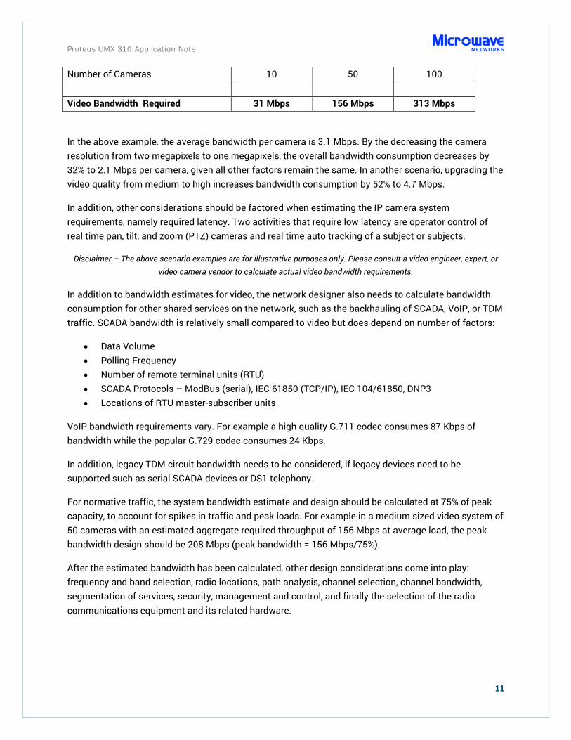
Number of Cameras 10 50 100 Video Bandwidth Required 31 Mbps 156 Mbps 313 Mbps
In the above example, the average bandwidth per camera is 3.1 Mbps. By the decreasing the camera resolution from two megapixels to one megapixels, the overall bandwidth consumption decreases by 32% to 2.1 Mbps per camera, given all other factors remain the same. In another scenario, upgrading the video quality from medium to high increases bandwidth consumption by 52% to 4.7 Mbps.
In addition, other considerations should be factored when estimating the IP camera system requirements, namely required latency. Two activities that require low latency are operator control of real time pan, tilt, and zoom (PTZ) cameras and real time auto tracking of a subject or subjects.
Disclaimer – The above scenario examples are for illustrative purposes only. Please consult a video engineer, expert, or video camera vendor to calculate actual video bandwidth requirements.
In addition to bandwidth estimates for video, the network designer also needs to calculate bandwidth consumption for other shared services on the network, such as the backhauling of SCADA, VoIP, or TDM traffic. SCADA bandwidth is relatively small compared to video but does depend on number of factors:
• Data Volume • Polling Frequency • Number of remote terminal units (RTU) • SCADA Protocols – ModBus (serial), IEC 61850 (TCP/IP), IEC 104/61850, DNP3 • Locations of RTU master-subscriber units
VoIP bandwidth requirements vary. For example a high quality G.711 codec consumes 87 Kbps of bandwidth while the popular G.729 codec consumes 24 Kbps.
In addition, legacy TDM circuit bandwidth needs to be considered, if legacy devices need to be supported such as serial SCADA devices or DS1 telephony.
For normative traffic, the system bandwidth estimate and design should be calculated at 75% of peak capacity, to account for spikes in traffic and peak loads. For example in a medium sized video system of 50 cameras with an estimated aggregate required throughput of 156 Mbps at average load, the peak bandwidth design should be 208 Mbps (peak bandwidth = 156 Mbps/75%).
After the estimated bandwidth has been calculated, other design considerations come into play: frequency and band selection, radio locations, path analysis, channel selection, channel bandwidth, segmentation of services, security, management and control, and finally the selection of the radio communications equipment and its related hardware.

Proteus UMX 310 Application Note
12
Conclusion
Proteus UMX’s best-in-class features of 310 Mbps throughput, 11 RF interference features, powerful network management, and integrated cybersecurity solution, make it uniquely suited for mission critical and industrial PTMP video, SCADA, VoIP, TDM, and data solutions. It can also be used for PTP deployments, when licensed spectrum is not available or required.
Furthermore, Microwave Networks, Inc. supports its products and customers directly or via authorized VARs. Third party distributors are not involved. So customers get immediate and direct support from Microwave Networks’ factory engineers and technicians (based in Stafford, Texas) or through trained and certified personnel. Our microwave system engineers can design your network, integrate your system with other devices in our factory, provide factory acceptance tests, supervise installation, conduct training, and provide warranty and maintenance support. All Microwave Networks products, including the UMX 310, include a two year warranty. You can rest assured that the UMX is fully supported.
The Proteus UMX today operates in a variety of organizations, serving the mission critical needs of public safety, municipalities, government agencies, utilities, and mining. These deployments support a variety of services including video surveillance, SCADA, VoIP, and TDM legacy devices.
Please contact a Microwave Networks Regional Director to learn more about the Proteus UMX 310 system and to schedule a demonstration.
Multiple Proteus UMX units

Proteus UMX 310 Application Note
13
About Microwave Networks
Microwave Networks is a trusted global provider of mission critical microwave communications products and services and cybersecurity solutions. Based in Stafford, Texas, the company designs, provides, installs, and services licensed and unlicensed, point-to-point and point-to-multipoint microwave systems. For over 47 years, Microwave Networks has provided reliable microwave communications products and services to public safety, government, utilities, mobile network operators, and industrial customers. Our commitment to mission critical microwave communications is proven in radios that operate with unmatched performance, hot-standby redundancy, low latency, and excellent system-gain.
Microwave Networks has a qualified team of trained and experienced microwave engineers, technicians, trainers, program managers, and administrators who know how to build, design, implement, and support reliable microwave networks. They are ready to help you with your microwave requirements.
Microwave Networks, Inc.
4000 Greenbriar Dr. Stafford, TX 77477
1-281-263-6500
www.microwavenetworks.com