the quantity variations of the high strength … using normal strength reinforcing bars and...
TRANSCRIPT

International Journal of Applied Engineering Research ISSN 0973-4562 Volume 12, Number 8 (2017) pp. 1488-1499
© Research India Publications. http://www.ripublication.com
1488
The Quantity Variations of the High-Strength Reinforcing Bars on the
Underground Parking in a Rigid-Frame Building
Seung-Ho Cho1 and Seunguk Na2
1Research Professor, Dankook University, Republic of Korea.
2PhD researcher, University of Manchester, United Kingdom.
2ORCID: 0000-0002-4043-4765
Abstract
It is dealt with the quantity variations of high-strength
reinforcing bars in the underground parking spaces. The
purpose of this study is to investigate the quantity variations
of the high-strength reinforcing bars on the underground
parking spaces in a rigid-structure building. Recently,
constructing high-rise buildings and long-span structure in the
architecture, engineering, and construction industry (AEC
industry). However, there are a number of difficulties such as
excessive reinforcing bars arrangement, failure of concrete
quality management, unnecessary quantity take-off and so
forth, when these types of structures and buildings are formed
utilising normal strength reinforcing bars and concrete. As
skyscrapers and long-span structures are getting more
common in the AEC industry, it is widely applied high
strength reinforcing bars, cement and supplementary materials
to sustain durability and stability. The test results indicate that
it would be possible to achieve the reduction of reinforcing
bars arrangement and lowering the amount of bar arrangement
when the high-strength rebars were applied to the
underground parking spaces in a rigid-frame structure.
Moreover, the reduced amount of bar arrangement will make
it possible to improve workability and constructability of
reinforced concrete structures.
INTRODUCTION
While it is popular to build skyscrapers and long-span
structures in recent years, there might be a number of
problems and difficulties such as deterioration of concrete
placement quality, unnecessary quantity take-off on
reinforcement and so forth to construct such buildings and
structures using normal strength reinforcing bars and concrete.
As high-rise buildings and long-span structures are getting
more common in this field of work, it is popular to apply
high-strength materials such as high-strength reinforcing bars,
carbon fibre, and high-strength cement to sustain durability
and stability. When such high-strength materials are utilised in
large scale structures, it would be beneficial for contractors to
lower the input of materials and to shorten the construction
time. For example, it would be possible to reduce the quantity
and size of arranging reinforcing bars and to simplify the
details of connections, splice or development between them.
As a result, it would be able to attain more durable structures
and buildings with reduced construction time and more
constructible methods.
Korea Concrete Institute (KCI) in South Korea regulates the
usage of reinforcing bar strength as not exceeding 550MPa for
the main reinforcement and 400MPa for the shear
reinforcement bars. Based on these regulations, it is
widespread to apply SD400 reinforcing bars to construct
buildings and structures in South Korea. As it is getting
common to build high-rise and long-span structures, it is
required to consider implementing high-strength materials
especially high-strength concrete and reinforcing bars.
According to the revised Structural Concrete Design Code and
Commentary (KCI, 2012) in South Korea, KCI revise the
maximum tensile strength of reinforcing bars from 550MPa to
600MPa. Besides, SD500 and SD600 tensile strength rebars
are recommended to apply in high-strength concrete by KCI.
However, research regarding high-strength reinforcing bars in
practice is rare and it is needed to investigate the usefulness
and effectiveness. The main goal of this study is to verify the
usefulness and effectiveness of SD500 and SD600 rebars in
the underground parking spaces in a rigid-frame structure
which are common to buildings in the town centre.
RESEARCH BACKGROUND
The purpose of this research is to investigate the quantity
variations of high-strength rebars on underground parking
spaces in rigid frame structures, which are popular to
construct for offices, apartments and commercial buildings in
South Korea. In this study, we explored the quantity variations
(the pure quantity, development and splice) using high-
strength rebars on beams, columns, walls and footings.
The reinforcing bars applied in the main reinforcement were
SD400, SD500 and SD600, and the shear reinforcement
rebars were also SD400, SD500 and SD600 of the tensile
strength. As for the main reinforcement with SD600 rebars,
the shear reinforcement was applied to SD500 reinforcing
bars. This research also examined the effect of reinforcement
bars’ diameters. The size variables in this study were D10,
D13 and D16 which are common to use high-rise buildings
and long span structure in the AEC industry. Specifically, all
the variables (D10, D13 and D16) was applied to SD400,
SD500 and SD600 specimens. D13 and D16 were examined
the specimens with SD400 rebars. Reinforcing bars over D16
were implemented SD400, SD500 and SD600 tests. Cases of
D10 and D13 were examined with SD500 rebars, and over
D16 reinforcing bars were combined with SD500 and SD600
samples. The tested members in this study are summarised in
Table 1.

International Journal of Applied Engineering Research ISSN 0973-4562 Volume 12, Number 8 (2017) pp. 1488-1499
© Research India Publications. http://www.ripublication.com
1489
Table 1. The details of the tested model
Items Slab Beam and
Girder
Column Wall Retaining wall Footing
Underground
parking spaces
Main
rebar
Shear
rebar
Main
rebar
Shear
rebar
Main
rebar
Shear
rebar
Main
rebar
Shear
rebar
Main
rebar
Shear
rebar
Main
rebar
Shear
rebar
o X o o o o o x o x o x
Details of the structures
The summary of the studied model is summarised in Table 2. The floor plan of this research is also depicted in Figure 1.
Table 2 Structural summary of the studied model
Purpose Number of stories
(Ground/basement)
Structural
type
Footing type Concrete compressive strength
(MPa)
Underground parking
space
0 / 1 Rigid-frame Bearing capacity of soil (Mat
footing) 𝑓𝑐𝑘 = 24𝑀𝑃𝑎
Figure 1. Floor plan of the underground parking (Left: ground floor, Right: basement floor)
International Journal of Applied Engineering Research ISSN 0973-4562 Volume 12, Number 8 (2017) pp. 1488-1499
© Research India Publications. http://www.ripublication.com
1490
APPLICATION OF THE DESIGN CODES
All the specimens in this research was designed in compliance with Structural Concrete Design Code and Commentary by Korea
Concrete Institute (KCI,2012; KBC, 2009; AKI, 2009).
Analysis of the reference of codes
Main reinforcement
1. Beams 1) Nominal flexural strength at section
𝑀𝑛 = 𝜌𝑓𝑦𝑏𝑑2(1 − 0.59𝜌𝑓𝑦
0.85𝑓𝑐𝑘)
𝑀𝑛 : Nominal flexural strength at section
𝑓𝑐𝑘: Specified compressive strength of concrete, MPa
𝑓𝑦: Specified yield strength of reinforcement, MPa
: Tension reinforcement ratio
𝑏: Width of compression face of member, mm
𝑑: Effective depth, mm 2) Minimum reinforcement ratio
𝜌𝑚𝑖𝑛 =0.25√𝑓𝑐𝑘
𝑓𝑦
, 𝑓𝑐𝑘 > 30𝑀𝑃𝑎
𝜌𝑚𝑖𝑛 =1.4
𝑓𝑦
, 𝑓𝑐𝑘 ≤ 30𝑀𝑃𝑎
SD400 is 0.35%, SD500 is 0.28% or lower than 20%, and SD600 is 0.23 % or lower than 33.3%
3) Minimum allowable strain
𝑓𝑦 = 400𝑀𝑃𝑎 Minimum allowable strain: 0.004, Reinforcement ratio: 0.714𝑏
𝑓𝑦 = 500𝑀𝑃𝑎 Minimum allowable strain: 0.005 ( 2ϵ𝑦 ), Reinforcement ratio: 0.688𝑏
𝑓𝑦 = 600𝑀𝑃𝑎 Minimum allowable strain: 0.005 (2ϵ𝑦), Reinforcement ratio: 0.667𝑏
4) Designing beam components
Design of non-seismic structures as single beam reinforced concrete, and composite reinforcing bars should be
applied to two for minimum bar arrangement
Design of composite parts in seismic structures should be considered the lateral loads.
5) Consideration of space for cracks control
2. Slabs 1) Shrinkage and temperature reinforcement
𝑊ℎ𝑒𝑛 𝑓𝑦 ≤ 400𝑀𝑃𝑎 → 0.002
𝑊ℎ𝑒𝑛 𝑓𝑦 > 400𝑀𝑃𝑎 → 0.002 × 400
𝑓𝑦
𝑓𝑦 = 400𝑀𝑃𝑎: 0.02, 𝑓𝑦 = 500𝑀𝑃𝑎: 0.0016, 𝑓𝑦 = 600𝑀𝑃𝑎: 0.0013 → 0.0014
Maximum bar space: 3 times of slab depth or less than 450𝑚𝑚
2) Limit of space for cracks control (1 way slabs)
3) Bars arrangement for horizontal load
3. Columns: calculating the amount of reinforcement for compression members a) 𝑃𝑛,𝑚𝑎𝑥 = 0.8 × [0.85𝑓𝑐𝑘(𝐴𝑔 − 𝐴𝑠𝑡) + 𝑓𝑦𝐴𝑠𝑡]
𝐴𝑔: 𝐺𝑟𝑜𝑠𝑠 𝑎𝑟𝑒𝑎 𝑜𝑓 𝑐𝑜𝑛𝑐𝑟𝑒𝑡𝑒 𝑠𝑒𝑐𝑡𝑖𝑜𝑛, 𝑚𝑚2
𝐴𝑠𝑡: 𝑇𝑜𝑡𝑎𝑙 𝑎𝑟𝑒𝑎 𝑜𝑓 𝑛𝑜𝑛𝑝𝑟𝑒𝑠𝑡𝑟𝑒𝑠𝑠𝑒𝑑 𝑙𝑜𝑛𝑔𝑖𝑡𝑢𝑑𝑖𝑛𝑎𝑙 𝑟𝑒𝑖𝑛𝑓𝑜𝑟𝑐𝑒𝑚𝑒𝑛𝑡, , 𝑚𝑚2
b) Minimum and maximum reinforcement ratio 0.01 ≤ 𝜌 ≤ 0.08
c) If a structure is high-rise and the section of the column is same in all floors, the dominant reinforcement ration is
minimum reinforcement under certain conditions.
d) When high strength reinforcing bars are used, it would be required to adjust the section of the column if we want
to reduce the input of reinforcing bars.
International Journal of Applied Engineering Research ISSN 0973-4562 Volume 12, Number 8 (2017) pp. 1488-1499
© Research India Publications. http://www.ripublication.com
1491
4. Walls: core walls 1) Horizontal reinforcement: the regulation is equal spacing (No reinforcing bars in section)
2) Vertical reinforcement
Under D16: 0.12% Exceeding D16: 0.15%
Horizontal reinforcement
Under D16: 0.2% Exceeding D16: 0.25%
Limitation
Vertical reinforcement: horizontal length of the wall/5, three times of the depth, or 450𝑚𝑚
Horizontal reinforcement: horizontal length of the wall/3, three times of the depth, or 450𝑚𝑚
3) There is no regulation in terms of reinforcement in wall regardless of 𝑓𝑦 . Thus, the amount of high-strength
reinforcing bars is same as the amount of SD400. Moreover, the efficiency would be lowered if the amount of
minimum reinforcement would be increased.
5. Footings 1) Design of footings should comply with the code of flexural members.
𝑊ℎ𝑒𝑛 𝑓𝑦 ≤ 400𝑀𝑃𝑎 𝑖𝑠 0.002
𝑊ℎ𝑒𝑛 𝑓𝑦 > 400𝑀𝑃𝑎 𝑖𝑠 0.002 ×400
𝑓𝑦
𝑓𝑦 = 400𝑀𝑃𝑎: 0.002, 𝑓𝑦 = 500𝑀𝑃𝑎: 0.0016, 𝑓𝑦 = 600𝑀𝑃𝑎: 0.00133 → 0.0014
2) When SD500 is used, 𝑓𝑦 would be reduced 20 %, and when SD600 is applied, 𝑓𝑦 would be deducted to 33.3 %.
3) The type of footing is soil bearing capacity of mat foundations.
6. Deflection There are none of variables affecting deflection, when we use high strength reinforcing bars. However, the deflection
would be slightly increased when the high strength reinforcing bars are used, since the cracked moment of inertia is
decreased. In this study, each specimen was designed in consideration of deflection and the value was relatively small
and negligible.
7. Cracks 1) Reinforcement space of controlling cracks
𝑆 = 375 (210
𝑓𝑠) − 2.5𝐶𝑐 , 𝑆 = 300 (
210
𝑓𝑠) , 𝑏𝑢𝑡 𝑓𝑠 = (2/3)𝑓𝑦
𝐶𝑐: 𝐶𝑙𝑒𝑎𝑟 𝑐𝑜𝑣𝑒𝑟 𝑜𝑓 𝑟𝑒𝑖𝑛𝑓𝑜𝑟𝑐𝑒𝑚𝑒𝑛𝑡, 𝑚𝑚
𝑓𝑠: 𝐶𝑎𝑙𝑐𝑢𝑙𝑎𝑡𝑒𝑑 𝑡𝑒𝑛𝑠𝑖𝑙𝑒 𝑠𝑡𝑟𝑒𝑠𝑠 𝑖𝑛 𝑟𝑒𝑖𝑛𝑓𝑜𝑟𝑐𝑒𝑚𝑒𝑛𝑡 𝑎𝑡 𝑠𝑒𝑟𝑣𝑖𝑐𝑒 𝑙𝑜𝑎𝑑𝑠, 𝑀𝑃𝑎
2) If the section of beams is large, especially the width of beam is large, the tests were carried out in consideration of
reducing the diameter of the reinforcing bars.
3) Intervals of controlling cracks on slabs
When SD400 is used, it is 235mm
𝑚𝑖𝑛 [375 ×210
266.66] − 2.5 × 20 = 245.31𝑚𝑚, 300 ×
210
266.66= 236.26𝑚𝑚
When SD500 is used, it is 186mm
𝑚𝑖𝑛 [375 ×210
333.33] − 2.5 × 20 = 186.25𝑚𝑚, 300 ×
210
333.33= 195.3𝑚𝑚
When SD600 is used, it is 146mm
𝑚𝑖𝑛 [375 ×210
400] − 2.5 × 20 = 146.87𝑚𝑚, 300 ×
210
400= 157.5
4) Intervals of controlling cracks on beams
When SD400 is used, it is 170mm
𝑚𝑖𝑛 [375 ×210
266.66] − 2.5 × 50 = 170.31𝑚𝑚, 300 ×
210
266.66= 236.55𝑚𝑚
When SD500 is used, it is 136mm
𝑚𝑖𝑛 [375 ×210
333.33] − 2.5 × 50 = 111.25𝑚𝑚, 300 ×
210
333.33= 189.00𝑚𝑚
When SD600 is used, it is 71mm

International Journal of Applied Engineering Research ISSN 0973-4562 Volume 12, Number 8 (2017) pp. 1488-1499
© Research India Publications. http://www.ripublication.com
1492
𝑚𝑖𝑛 [375 ×210
400] − 2.5 × 20 = 71.875𝑚𝑚, 300 ×
210
400= 157.5𝑚𝑚
8. Development and splice 1) The development length
a) Development length for deformed bars in compression: 𝑙𝑑𝑏 =0.25𝑑𝑏𝑓𝑦
𝜆√𝑓𝑐𝑘
b) Development length for deformed bars in tension: 𝑙𝑑𝑏 =0.90𝑑𝑏𝑓𝑦
𝜆√𝑓𝑐𝑘
𝛼𝛽𝛾
(𝑐+𝐾𝑡𝑟
𝑑𝑏)
c) Development length for standard hooks in tension: 𝑙ℎ𝑏 =0.24𝛽𝑑𝑏𝑓𝑦
𝜆√𝑓𝑐𝑘
𝑑𝑏: 𝑁𝑜𝑚𝑖𝑛𝑎𝑙 𝑑𝑖𝑎𝑚𝑒𝑡𝑒𝑟 𝑜𝑓 𝑏𝑎𝑟, 𝑚𝑚
𝛼: 𝑅𝑒𝑖𝑛𝑓𝑜𝑟𝑐𝑒𝑚𝑒𝑛𝑡 𝑙𝑜𝑐𝑎𝑡𝑖𝑜𝑛 𝑓𝑎𝑐𝑡𝑜𝑟
𝛽: 𝐶𝑜𝑎𝑡𝑖𝑛𝑔 𝑓𝑎𝑐𝑡𝑜𝑟
𝜆: 𝐿𝑖𝑔ℎ𝑡 − 𝑤𝑒𝑖𝑔ℎ𝑡 𝑎𝑔𝑔𝑟𝑒𝑔𝑎𝑡𝑒 𝑐𝑜𝑛𝑐𝑟𝑒𝑡𝑒 𝑓𝑎𝑐𝑡𝑜𝑟
𝛾: 𝑅𝑒𝑖𝑛𝑓𝑜𝑟𝑐𝑒𝑚𝑒𝑛𝑡 𝑠𝑖𝑧𝑒 𝑓𝑎𝑐𝑡𝑜𝑟
𝑐: 𝑆𝑝𝑎𝑐𝑖𝑛𝑔 𝑜𝑟 𝑐𝑜𝑣𝑒𝑟 𝑑𝑖𝑚𝑒𝑛𝑠𝑖𝑜𝑛
𝐾𝑡𝑟: 𝑇𝑟𝑎𝑛𝑠𝑣𝑒𝑟𝑠𝑒 𝑟𝑒𝑖𝑛𝑓𝑜𝑟𝑐𝑒𝑚𝑒𝑛𝑡 𝑖𝑛𝑑𝑒𝑥
2) Beams: Applied to the general design codes
3) Vertical members: Applied seismic resistance design
4) Slabs: Applied 1 way slab design code
5) Footings: Applied codes in accordance with the design code of beams
Shear reinforcement
1. Beams 1) The strength of concrete with shear and flexural moment
𝑉𝑐 =1
6√𝑓𝑐𝑘𝑏𝑤𝑑
2) Space of shear reinforcement
a) 𝑉𝑢 <∅𝑉𝑐
2: 𝑆ℎ𝑒𝑎𝑟 𝑟𝑒𝑖𝑛𝑓𝑜𝑟𝑐𝑒𝑚𝑒𝑛𝑡 𝑖𝑠 𝑛𝑜𝑡 𝑟𝑒𝑞𝑢𝑖𝑟𝑒𝑑
b) ∅𝑉𝑐
2< 𝑉𝑢 ≤ ∅𝑉𝑐 : 𝑆ℎ𝑒𝑎𝑟 𝑟𝑒𝑖𝑛𝑓𝑜𝑟𝑐𝑒𝑚𝑒𝑛𝑡 𝑖𝑠 𝑟𝑒𝑞𝑢𝑖𝑟𝑒𝑑
𝑊ℎ𝑒𝑛 𝑠ℎ𝑒𝑎𝑟 𝑟𝑒𝑖𝑛𝑓𝑜𝑟𝑐𝑒𝑚𝑒𝑛𝑡 𝑖𝑠 𝑟𝑒𝑞𝑢𝑟𝑒𝑑, 𝑚𝑖𝑛 [600,𝑑
2, 𝑜𝑟 𝑠 =
𝐴𝑣𝑓𝑦
0.35𝑏𝑤]
c) ∅𝑉𝑐 < 𝑉𝑢 ≤ ∅𝑉𝑐 + ∅1
3√𝑓𝑐𝑘𝑏𝑤𝑑: 𝑆ℎ𝑒𝑎𝑟 𝑟𝑒𝑖𝑛𝑓𝑜𝑟𝑐𝑒𝑚𝑒𝑛𝑡 𝑖𝑠 𝑟𝑒𝑞𝑢𝑖𝑟𝑒𝑑
𝑊ℎ𝑒𝑛 𝑠ℎ𝑒𝑎𝑟 𝑟𝑒𝑖𝑛𝑓𝑜𝑟𝑐𝑒𝑚𝑒𝑛𝑡 𝑖𝑠 𝑟𝑒𝑞𝑢𝑖𝑟𝑒𝑑,
𝑚𝑖𝑛 [600,𝑑
2, 𝑠 =
𝐴𝑣𝑓𝑦
0.35𝑏𝑤, 𝑜𝑟 𝑆 =
∅𝐴𝑣𝑓𝑦𝑑
∅𝑉𝑠]
d) ∅𝑉𝑐 + ∅1
3√𝑓𝑐𝑘𝑏𝑤𝑑 < 𝑉𝑢 ≤ ∅𝑉𝑐 + +∅
2
3√𝑓𝑐𝑘𝑏𝑤𝑑
: 𝑆ℎ𝑒𝑎𝑟 𝑟𝑒𝑖𝑛𝑓𝑜𝑟𝑐𝑒𝑚𝑒𝑛𝑡 𝑖𝑠 𝑟𝑒𝑞𝑢𝑖𝑟𝑒𝑑
𝑊ℎ𝑒𝑛 𝑠ℎ𝑒𝑎𝑟 𝑟𝑒𝑖𝑛𝑓𝑜𝑟𝑐𝑒𝑚𝑒𝑛𝑡 𝑖𝑠 𝑟𝑒𝑞𝑢𝑖𝑟𝑒𝑑,
𝑚𝑖𝑛 [300,𝑑
4, 𝑜𝑟 𝑆 =
∅𝐴𝑣𝑓𝑦𝑑
∅𝑉𝑠]
Then, 𝑉𝑠 =𝐴𝑣𝑓𝑦𝑑
𝑠
3) Minimum shear reinforcement
All the flexural members (The factored shear strength (𝑉𝑢) is not exceeded a half of the minimum shear strength)
should place shear reinforcement.
𝐴𝑣,𝑚𝑖𝑛 = 0.625√𝑓𝑐𝑘𝑏𝑤𝑠
𝑓𝑦𝑡
However, the minimum shear reinforcement 𝑉𝑠 should not exceed 0.35𝑏𝑤 𝑠 𝑓𝑦𝑡⁄
4) Maximum shear strength 𝑉𝑠 should lower than (2 √𝑓𝑐𝑘 3⁄ )𝑏𝑤𝑑
International Journal of Applied Engineering Research ISSN 0973-4562 Volume 12, Number 8 (2017) pp. 1488-1499
© Research India Publications. http://www.ripublication.com
1493
2. Columns 1) The strength of compressive axial force members
𝑉𝑐 =1
6(1 +
𝑁𝑢
14𝐴𝑔) √𝑓𝑐𝑘𝑏𝑤𝑑
2) Space of shear reinforcement
a) 𝑉𝑢 < ∅𝑉𝑐 : Shear reinforcement is not required
b) 𝑉𝑢 > ∅𝑉𝑐 : Shear reinforcement is required
c) Shear reinforcement
- Structures where locate in non-seismic areas
𝑚𝑖𝑛[𝑚𝑎𝑖𝑛 𝑟𝑒𝑖𝑛𝑓𝑜𝑟𝑐𝑒𝑚𝑒𝑛𝑡 × 16, ℎ𝑜𝑜𝑝 × 48, 𝑜𝑟 ℎ𝑎𝑙𝑓 𝑜𝑓 𝑡ℎ𝑒 𝑚𝑖𝑛𝑖𝑚𝑢𝑚 𝑜𝑓 𝑏 𝑜𝑟 ℎ]
- Structures where locate in seismic area
𝑚𝑖𝑛[𝑚𝑎𝑖𝑛 𝑟𝑒𝑖𝑛𝑓𝑜𝑟𝑐𝑒𝑚𝑒𝑛𝑡 × 16, ℎ𝑜𝑜𝑝 × 24, 𝑚𝑖𝑛𝑖𝑚𝑢𝑚 𝑜𝑓 𝑏 𝑜𝑟 ℎ, 𝑜𝑟 300]
3) Maximum shear strength 𝑉𝑠 should be lower than 2(2√𝑓𝑐𝑘 3⁄ )𝑏𝑤𝑑
3. Walls Generally, shear reinforcement in walls is similar to the design of shear reinforcement design in beams. However, there is
slight difference of the arrangement in the vertical shear reinforcement, when the space of vertical and horizontal shear
reinforcement, and the ration of shear span is very small.
1) Shear strength 𝑉𝑐 would be selected minimum value,
𝑉𝑐 = 0.28𝜆√𝑓𝑐𝑘ℎ𝑑 +𝑁𝑢𝑑
4𝑙𝑤 or
𝑉𝑐 = [0.05𝜆√𝑓𝑐𝑘 +𝑙𝑤(0.10𝜆√𝑓𝑐𝑘+0.2
𝑁𝑢𝑙𝑤ℎ
)
𝑀𝑢𝑉𝑢
−𝑙𝑤2
] ℎ𝑑
𝜆 : Light-weight aggregate concrete factor
ℎ : Overall thickness or height of member, 𝑚𝑚
𝑑 : Distance from extreme compression fibre to centroid of longitudinal tension reinforcement, 𝑚𝑚
𝑁𝑢 : Factored axial force normal to cross section occurring simultaneously with 𝑉𝑢 or 𝑇𝑢 is to be taken as
positive for compression and negative for tension, 𝑘𝑁
𝑙𝑤 : Length of entire wall or length of segment of wall considered in direction of shear force, 𝑚𝑚
2) When 𝑉𝑢 > ∅𝑉𝑐, the arrangement of horizontal shear reinforcement is,
𝑉𝑠 =𝐴𝑣ℎ𝑓𝑦𝑑
𝑆ℎ
𝐴𝑣ℎ: Area of shear reinforcement parallel to flexural tension reinforcement within spacing, 𝑚𝑚
𝑆ℎ : Centre-to-centre spacing of longitudinal shear or torsion reinforcement, 𝑚𝑚
3) Minimum area of reinforcement and spacing
𝑉𝑢 ≤ ∅ 𝑉𝑐 2⁄ : Comply with a) ~d), or reinforcement of walls
𝑉𝑢 > ∅ 𝑉𝑐 2⁄ : Comply with a) ~ d)
a) 𝜌ℎ = 0.0025
b) Reinforcement of horizontal shear force: Lower than 𝑆ℎ = 𝑙𝑤 5⁄ , 3ℎ, or 450𝑚𝑚
c) 𝜌𝑙 = 0.0025 + 0.5 (2.5 −ℎ𝑤
𝑙𝑤) (𝜌ℎ − 0.0025)
d) Reinforcement of vertical shear force: Lower than 𝑆𝑣 = 𝑙𝑤, 3ℎ, or 450𝑚𝑚
First of all, the splice and pure quantity of reinforcing bars
were analysed in order to comprehend the relationships
between the different sizes and the strength of the rebars. The
used reinforcing bars in this study were applied differently for
the parts of the underground parking space. SD400 and
SD500 with D10 and D13 diameter reinforcing bars were
applied to slabs. When it comes to beams, SD400 with D25,
SD500 with D22, and SD600 with D19 were used. The yield
strength of the main reinforcement in columns was SD400,
SD500 and SD600. All the specimen was manufactured with
D22 rebars in columns. The hoops in columns were applied
D10 with SD400 and SD500. As for the walls in the basement,
the vertical reinforcement was SD400, SD500 and SD600
which D13 and D16 rebars were applied. For the horizontal
reinforcing bars, SD400 and SD500 yield strength with D10
and D13 rebars were put in the basement concrete. For
footings, D16, D19 and D22 reinforcing bars were used for
SD400 and SD500, and D13, D16, and D19 rebars were
applied to SD600 specimens. In addition, the relationships
between the strength of reinforcing bars and the quantity of
them were also considered to corroborate the influence of
high-strength rebars on the quantity of reinforcement

International Journal of Applied Engineering Research ISSN 0973-4562 Volume 12, Number 8 (2017) pp. 1488-1499
© Research India Publications. http://www.ripublication.com
1494
arrangement. The quantity of reinforcement was examined
both the increment of slice and development, and the decrease
of reinforcement by member force. The tests were firstly
carried out SD400, SD500 and SD600 for all the reinforcing
bars. The following tests were conduceted D10 and D13
rebars with SD400 and SD500. Then, SD500 and SD600
tensile strength reinforcing bars were applied to rebars which
were more than D16 diameter. Finally, D10 and D13
reinforcing bars were used on SD500 tensile strength
reinforcing bars, and SD500 and SD600 rebars were tested
with more than D16 diameter reinforcing bars. The test results
of this research show in the following section.
The relationships between size and strength of the
reinforcing bars
Slabs
The test result indicates that the pure quantity of reinforcing
bars in slabs is reduced as the strength of the rebars grows in
general. Table 3. The quantity of reinforcement in slabs (Unit:
Ton) summarises the quantity of rebars of the pure quantity,
splice and development on slabs. As the yield strength of the
reinforcing bars was increased, the amount of reinforcing bars
on SD500 and SD600 was reduced 20.7 per cent and 30.2 per
cent respectively comparing with SD400 rebars.
Table 3. The quantity of reinforcement in slabs (Unit: Ton)
Yield
strength
Diameter Pure
quantity
Development /
splice
Total
SD400 D10 0.93 0.66 0.99
D13 57.29 4.77 62.06
D16 7.29 0.79 8.08
Subtotal 65.5 (100%) 5.6 (100%) 71.1 (100%)
SD500 D10 18.07 1.30 19.37
D13 29.30 2.96 32.26
D16 3.02 0.49 3.51
Subtotal 51.69
(78.9%)
4.75 (84.5%) 56.44
(79.3%)
SD600 D10 26.60 1.97 28.57
D13 18.66 2.39 21.05
Subtotal 45.26
(69.1%)
4.36 (77.6%) 49.62
(69.8%)
Beams
The quantity of reinforcement on beams was analysed in three
folds. Main reinforcement and shear reinforcement were
analysed separately and then the combined amount (the sum
of main and shear reinforcement) was examined in the end.
The following section displays the analysed data of beams.
Main reinforcement The overall quantity variations of the main reinforcement on
beams were reduced as the yield strength of the reinforcing
bars was increased. As seen in Table 4, the pure quantity of
reinforcement with SD500 was reduced 21.0 per cent
comparing with SD400. When the development and splice
were considered, the total quantity was decreased 20.0 per
cent. SD600 rebars were also reduced 33.5 per cent of the
pure quantity and 26.5 per cent of the total quantity.
Table 4. The quantity of main reinforcement on beams and
girders
Yield
strength Diameter
Pure
quantity
Development
/ splice Total
SD400 D25 81.18
(100%) 13.7 (100%)
94.88
(100%)
SD500 D22 64.10
(79.0%) 11.82 (86.3%)
75.92
(80.0%)
SD600 D19 54.02
(66.5%) 7.89 (57.6%)
61.91
(65.3%)
Shear reinforcement The test results of shear reinforcement on beams were similar
to the effect of the high-strength main reinforcement on
beams. The quantity of reinforcement, development and splice
was reduced as the strength of the reinforcing bars was
increased. As seen in Table 5, the pure quantity of
reinforcement was lowered as the strength of the reinforcing
bars was increased. In addition, the development and splice
were reduced when the high-strength rebars were
implemented.
Table 5. The quantity of shear reinforcement on beams and
girders (Unit: Ton)
Yield strength Diameter Pure quantity
SD400 D13 31.79 (100%)
SD500 D13 25.35 (79.7%)
Combination of the main and shear reinforcement The combined quantity of the main and shear reinforcement
was reduced in all aspects. The total quantity of reinforcement
was reduced 20.1 per cent on SD500 and 31.1 per cent on
SD600. The test results summarise in Table 6.
Table 6. The combined quantity of main and shear
reinforcement on beams and girders (Unit: Ton)
Yield
strength
Main rebar Shear
rebar
Total
Pure
quantity
Development
/Splice
Subtotal
SD400 81.18
(100%)
13.7 (100%) 94.88
(100%)
31.79
(100%)
126.67
(100%)
SD500 64.10
(79.0%)
11.82
(86.3%)
75.92
(80.0%)
25.35
(79.7%)
101.27
(79.9%)
SD600 54.02
(66.5%)
7.89 (57.6%) 61.91
(65.3%)
25.35
(79.7%)
87.26
(68.9%)
Columns
While the pure quantity of reinforcing bars on columns was
decreased on SD500 and SD600 comparing with SD400, the
amount of reinforcing bars on development and splice was
increased. However, the total quantity of rebars on columns
indicates reduced tendency since the increment of the pure
quantity was slightly larger than the development and splice.
As shown in Table 7, the total quantity considering pure
quantity of reinforcement, development, splice and hoops
were reduced 3.0 per cent on SD500 and 7.2 per cent on
SD600 comparing with SD400 reinforcing bars.

International Journal of Applied Engineering Research ISSN 0973-4562 Volume 12, Number 8 (2017) pp. 1488-1499
© Research India Publications. http://www.ripublication.com
1495
Table 7. The quantity of reinforcement in walls (Unit: Ton)
Yield strength Main rebar Shear rebar Total
Pure quantity Development
/Splice
Subtotal
SD400 15.79 (100%) 7.36 (100%) 23.15 (100%) 2.54 (100%) 25.69 (100%)
SD500 14.16 (89.7%) 8.23 (111.8%) 23.39 (96.7%) 2.54 (100%) 24.93 (97%)
SD600 12.54 (79.4%) 8.75 (118.9%) 21.29 (92.0%) 2.54 (100%) 23.83 (92.8%)
Walls
The quantity of reinforcing bars on walls is summarised in
Table 8. The arrangement of rebars on walls was considered
both vertical and horizontal reinforcement. Both horizontal
and vertical reinforcement indicate the lowering of the
material input even though the quantity of development and
splice were increased. SD500 rebars would be able to lower
the quantity for 3.8 per cent comparing with SD400 and
SD600 was 7.3 per cent lower than SD400 reinforcing bars.
Table 8. The quantity of reinforcement in walls (Unit: Ton)
Yield strength Vertical rebar Horizontal rebar Total
Pure quantity Development/
Splice
Subtotal Pure quantity Development/
Splice
Subtotal
SD400 19.74 (100%) 3.85
(100%)
23.59
(100%)
9.28
(100%)
0.48
(100%)
9.76
(100%)
33.35
(100%)
SD500 17.83
(90.3%)
4.37
(113.5%)
22.20
(94.1%)
9.28
(100%)
0.6
(125.0%)
9.88
(101.2%)
33.08
(96.2%)
SD600 16.98
(86.0%)
4.07
(105.7%)
21.05
(89.2%)
9.28
(100%)
0.6
(125.0%)
9.88
(101.2%)
30.93
(92.7%)
Footings
The pure quantity, development, splice and total quantity of
reinforcing bars on footings are summarised in Table 9. The
test results indicate that 14.4 per cent reduction on SD500 and
27.2 per cent decrease on SD600 comparing with SD400.
Table 9. Quantity of reinforcement in footings (Unit: Ton)
Yield strength Diameter Pure quantity Development / splice Total
SD400 D16 64.58 14.15 78.73
D19 27.62 4.35 31.97
D22 47.92 17.11 65.03
Subtotal 14012 (100%) 35.61 (100%) 175.73 (100%)
SD500 D16 53.06 13.21 66.27
D19 23.39 4.63 28.02
D22 40.27 15.82 56.09
Subtotal 116.72 (82.8%) 33.66 (94.5%) 150.38 (85.6%)
SD600 D13 16.94 4.17 21.11
D16 46.21 11.33 57.54
D19 36.18 13.06 49.24
Subtotal 99.33 (70.9%) 28.56 (80.2%) 127.89 (72.8%)
Comparisons of the total quantity of reinforcing bars by yield
strength
1. As shown in Table 10 and Figure 2, the total quantity of
reinforcement was reduced 15.6 per cent on SD500 and
26.1 per cent on SD600 comparing with SD400, when
SD500 and SD600 were applied to slabs, beams or
girders, columns, walls, and footings.

International Journal of Applied Engineering Research ISSN 0973-4562 Volume 12, Number 8 (2017) pp. 1488-1499
© Research India Publications. http://www.ripublication.com
1496
Table 10. The quantity of reinforcement by yield strength (Unit: Ton)
Member Slabs Beams / Girders Columns Walls Footings Total
SD
400
Pure quantity 65.61 112.97 18.33 29.02 140.12 365.95
(100%)
Development /
Splice
5.62 13.7 7.36 4.33 35.61 66.62
(100%)
Subtotal 71.13
(100%)
126.67
(100%)
25.69
(100%)
33.35
(100%)
175.73
(100%)
432.57
(100%)
SD
500
Pure quantity 51.69 89.45 16.70 27.11 116.72 301.67
(82.4%)
Development /
Splice
4.75 11.82 8.23 4.97 33.66 63.43
(95.2%)
Subtotal 56.44
(79.3%)
101.27
(79.9%)
24.93
(97.0%)
32.08
(96.2%)
150.38
(85.6%)
365.10
(84.4%)
SD
600
Pure quantity 45.26 79.37 15.08 26.26 99.33 265.3
(72.5%)
Development
/ Splice
4.36 7.89 8.75 4.67 28.56 54.23
(81.4%)
Subtotal 49.62
(69.8%)
87.26
(69.9%)
23.83
(92.7%)
30.93
(92.7%)
127.89
(72.8%)
319.53
(73.9%)
Note: All the reinforcing bars was applied SD400, SD500 and SD600
Figure 2. The quantity of main reinforcement by yield strength variables 1
2. The test results in Table 11 indicate SD400 reinforcing bars with D10 and D13 in diameter, and SD400, SD500 and SD600
using over D16 rebars. As shown in Table 11 and Figure 3, the total quantity of reinforcement was reduced 11.1 per cent on
SD500 rebars comparing with SD400. Besides, it would be possible to lower the input amount of reinforcing bars up to
20.6 per cent, when SD600 rebars were applied comparing with SD400 ones.
0
20
40
60
80
100
120
Slab Beam&Girder Column Wall Footing TOTAL
SD400 SD500 SD600
The q
uantity
of
rela
tive rein
forc
ing b
ar (%
)
100
79.3
69.8
100
79.9
68.9
10097.0
92.8
100
96.292.7
100
85.6
72.8
100
84.4
73.9

International Journal of Applied Engineering Research ISSN 0973-4562 Volume 12, Number 8 (2017) pp. 1488-1499
© Research India Publications. http://www.ripublication.com
1497
Table 11. The quantity of reinforcement with combined reinforcing bars 1 (Unit: Ton)
Member Slabs Beams / Girders Columns Walls Footings Total
SD
400
Pure quantity 65.51 112.97 18.33 29.02 140.12 365.98
(100%)
Development / Splice 5.62 13.7 7.36 4.33 35.61 66.62
(100%)
Subtotal 71.13
(100%)
126.67
(100%)
25.69
(100%)
33.35
(100%)
175.73
(100%)
432.57
(100%)
SD400
+
SD500
Pure quantity 64.05 95.89 16.70 28.04 116.72 321.40
(87.8%)
Development
/ Splice
5.46 11.82 8.23 4.14 33.66 63.31
(95.0%)
Subtotal 69.51
(97.7%)
107.71
(85.0%)
24.93
(97.0%)
32.18
(96.5%)
150.38
(85.6%)
384.71
(88.9%)
SD400
+
SD600
Pure quantity 61.22 85.81 15.08 27.55 99.33 288.99
(79.0%)
Development
/ Splice
5.08 7.89 8.75 4.04 28.56 54.32
(81.5%)
Subtotal 66.3
(93.2%)
93.70
(74.0%)
23.83
(92.8%)
31.59
(94.7%)
127.89
(72.8%)
343.31
(79.4%)
Note: D10 and D13 were applied SD400, D16 or more was applied SD400, SD500 and SD600.
Figure 3. The quantity of main reinforcement by the yield strength variables 2 (Unit: Ton)
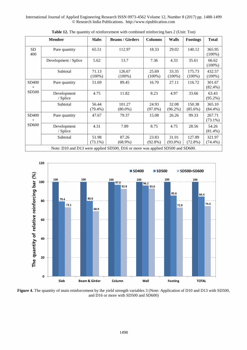
3. The data show in Table 12 that it would be possible to gain 15.6 per cent reduced quantity of reinforcement on SD500 with
D10 and D13 reinforcing bars comparing with SD400. In addition, the test result indicates that 25.6 per cent reduction of
rebars, when the combination of SD500 and SD600 reinforcing bars were used in the specimens. In general, high-strength
reinforcing bars would be more beneficial and efficient to lower the total quantity of reinforcement comparing with lower
yield strength materials (See Figure 4).
International Journal of Applied Engineering Research ISSN 0973-4562 Volume 12, Number 8 (2017) pp. 1488-1499
© Research India Publications. http://www.ripublication.com
1498
Table 12. The quantity of reinforcement with combined reinforcing bars 2 (Unit: Ton)
Member Slabs Beams / Girders Columns Walls Footings Total
SD
400
Pure quantity 65.51 112.97 18.33 29.02 140.12 365.95
(100%)
Development / Splice 5.62 13.7 7.36 4.33 35.61 66.62
(100%)
Subtotal 71.13
(100%)
126.67
(100%)
25.69
(100%)
33.35
(100%)
175.73
(100%)
432.57
(100%)
SD400
+
SD500
Pure quantity 51.69 89.45 16.70 27.11 116.72 301.67
(82.4%)
Development
/ Splice
4.75 11.82 8.23 4.97 33.66 63.43
(95.2%)
Subtotal 56.44
(79.4%)
101.27
(80.0%)
24.93
(97.0%)
32.08
(96.2%)
150.38
(85.6%)
365.10
(84.4%)
SD400
+
SD600
Pure quantity 47.67 79.37 15.08 26.26 99.33 267.71
(73.1%)
Development
/ Splice
4.31 7.89 8.75 4.75 28.56 54.26
(81.4%)
Subtotal 51.98
(73.1%)
87.26
(68.9%)
23.83
(92.8%)
31.01
(93.0%)
127.89
(72.8%)
321.97
(74.4%)
Note: D10 and D13 were applied SD500, D16 or more was applied SD500 and SD600.
Figure 4. The quantity of main reinforcement by the yield strength variables 3 (Note: Application of D10 and D13 with SD500,
and D16 or more with SD500 and SD600)
0
20
40
60
80
100
120
Slab Beam&Girder Column Wall Footing TOTAL
SD400 SD500 SD500+SD600
The q
uantity
of
rela
tive rein
forc
ing b
ar
(%)
100
79.4
73.1
100
80.0
68.9
10097.0
92.8
100
96.293.0
100
85.6
72.8
100
84.4
74.4

International Journal of Applied Engineering Research ISSN 0973-4562 Volume 12, Number 8 (2017) pp. 1488-1499
© Research India Publications. http://www.ripublication.com
1499
CONCLUSIONS
The main purpose of this research is to corroborate the
effectiveness and practicality of the high-strength reinforcing
bars in the underground parking space in a rigid-frame
structure building (Rahmen structure) which is popular as well
as resist vertical and lateral loads at the same time in concrete
structures.
1. When SD500 and SD600 reinforcing bars were applied in
the underground parking structures, the overall strength
of the reinforcing bars would be increased 25 per cent and
50 per cent compared to SD400 rebars. When the
structures on SD500 and SD600 were designed in
compliance with KCI Design Codes, the quantity of
reinforcing bars would be reduced approximately 20 per
cent and 33 per cent respectively. In addition, the length
of splice and development on SD500 and SD600 would
be increased up to 25 per cent and 50 per cent
2. It was prominent for the underground structure buildings
to reduce the amount of reinforcing bars, since the loads
applied in the underground parking structures are heavier
so the size of members such as slabs, beams and footings
as well as the design of such members are designed by
strength rather than the minimum reinforcement. Another
cause of lowering the amount of reinforcing bars might
be the length of splice and development was decreased as
the quantity and the size of rebars were diminished. As a
result of these factors, the overall amount of reinforcing
bars shows reduced, when the high-strength reinforcing
bars were applied to the specimen. On the other hand, for
columns and walls, the length of splice and development
was increased, and the hoops and horizontal rebars were
not lowered. Therefore, the quantity of reinforcing bars
was not reduced and the effect of reduction was marginal
on columns and walls.
3. In general, it will be possible to lower the pure quantity of
reinforcing bars arrangement in all aspects. The test result
shows that we would be able to reduce 17.6 per cent on
SD500 compared with SD400 rebars. For SD600, the
amount of reinforcing bars would be lowered 27.5 per
cent compared with SD400. When the length of splice
and development was considered, the quantity of
reinforcing bars on SD500 and SD600 were 15.6 per cent
and 26.1 per cent respectively compared with SD400
rebars. In this aspect, it was negligible that the rate of
increased amount of reinforcing bars on the splice and
development was 1.4 ~ 2.0 per cent. The reason for this
result is that the reduced amount of pure reinforcement is
far greater than the quantity of the splice and
development when the high-strength reinforcing bars
were applied in the specimens.
4. The most effective method to reduce the amount of
reinforcing bars arrangement was using SD600 on all the
reinforcement. However, when we apply all the
reinforcement with SD600 rebars, there is a restriction to
use the shear reinforcement only with SD500. In this case,
there would be a difficulty to adopt this method in
practice, since the size of rebars is increased and there
would be a possibility of causing segregation and placing
of concrete.
5. As a result, it would be possible to attain the reduction of
reinforcing bars arrangement and lowering the amount of
work on site. Moreover, the decreased amount of bar
arrangement will lead to reduce the reinforcement work
as well as to improve the constructability in concrete
structures. The reduced amount of resources in concrete
structures would be able to achieve lean construction as
well as sustainability in the AEC industry. Ultimately, it
would be possible to attain the improved quality and
efficiency of reinforced concrete structures.
REFERENCES
[1] ACI 2004. ACI Detailing Manual 2004, Publication SP-66(04), American Concrete Institute.
[2] ACI Committee 318, Building Code Requirements for
Structural Concrete (ACI 318-08) and Commentary
(ACI 318R-08), American Concrete Institute
[3] AIK 2009. Korean Building Code-Structure, Seoul,
Architectural Institute of Korea.
[4] ASSOCIATION, T. K. S. E. 2010. Reinforced concrete bar arrangement detail, Seoul, The Korean
Structural Engineers Association.
[5] Black, W. C., Field corrections to partially embedded
reinforcing bars, ACI Journal Proceedings, 70 (10), 690-691
[6] D.Y., M. 2013. Flexural behaviour of concrete beams
reinforced with high-strength steel bars. Journal of Korean Society of Disaster & Security, 13, 107-113.
[7] G-H, H. 2011. Flexural performance evaluation of
reinforced concrete beams with high-strength
reinforcing bars. Journal of the Korean Institute of Korea, Structure and Construction, 27, 103-110.
[8] International Code Council, 2006, International
Building Code, Building Officials and Code
Administrators International INC.
[9] Joint ACI-ASCE Committee 421, 1999, Shear
reinforcement for slabs (ACI 421. 1R-99)
(Reapproved 2006), American Concrete Institute, MI.
[10] Joint ACI-ASCE Committee 352, 2002,
Recommendations for Design of Beam-Column
Connections in Monolithic Reinforced Concrete
Structure (ACI 352R-02), American Concrete Institute,
Frarmington Hills, MI.
[11] J-S, K., D-Y, K., S-H, E. & Y-N, K. 2003. A study on
the practical use of high-strength bar. Magazine of the Korea Concrete Institute, 15, 86-89.
[12] J.Y., K. & D.W., K. 2008. A study on the economic
evaluation model of splice of reinforcement bar
(SD500). Journal of the Korean Institute of Building Construction, 8, 71-76.
[13] KCI 2012. Structural Concrete Code and Commentary, Korea Concrete Institute.