the ranges - r & d | home · furthermore, for the first time abb sace has also developed a...
TRANSCRIPT
ABB SACE 2/1
2
The ranges
Index
Tmax circuit-breakers for power distribution
Electrical characteristics ........................................................................................................ 2/4
General characteristics .......................................................................................................... 2/6
Thermomagnetic releases ...................................................................................................... 2/8
Electronic releases ............................................................................................................... 2/11
Tmax circuit-breakers for motor protection
Electrical characteristics ...................................................................................................... 2/20
Protection against short-circuit ............................................................................................ 2/22
Integrated protection: PR222MP ......................................................................................... 2/24
Tmax circuit-breakers for applications up to 1000 V
Electrical characteristics ...................................................................................................... 2/32
Switch-disconnectors
Electrical characteristics ...................................................................................................... 2/36

ABB SACE
2
2/3
Circuit-breakers for powerdistribution
Index
Tmax circuit-breakers for power distribution
Electrical characteristics ........................................................................................................ 2/4
General characteristics .......................................................................................................... 2/6
Thermomagnetic releases ...................................................................................................... 2/8
Electronic releases ............................................................................................................... 2/11

ABB SACE2/4
2
Circuit-breakers for power distributionElectrical characteristics
TERMINAL CAPTION
F = Front
EF = Front extendedES = Front extended spread
FC Cu = Front for copper cablesFC CuAl = Front for CuAl cables
Tmax T1 1P Tmax T1Rated uninterrupted current, Iu [A] [A] 160 160
No. Poles [No.] 1 3/4Rated service voltage, Ue (AC) 50-60 Hz [V] 240 690
(DC) [V] 125 500Rated impulse withstand voltage, Uimp [kV] 8 8
Rated insulation voltage, Ui [V] 500 800Test voltage at industrial frequency for 1 min. [V] 3000 3000
Rated ultimate short-circuit breaking capacity, Icu B B C N(AC) 50-60 Hz 220/230 V [kA] 25(*) 25 40 50
(AC) 50-60 Hz 380/415 V [kA] – 16 25 36(AC) 50-60 Hz 440 V [kA] – 10 15 22
(AC) 50-60 Hz 500 V [kA] – 8 10 15(AC) 50-60 Hz 690 V [kA] – 3 4 6
(DC) 250 V - 2 poles in series [kA] 25 (at 125 V) 16 25 36(DC) 250 V - 3 poles in series [kA] – 20 30 40
(DC) 500 V - 2 poles in series [kA] – – – –(DC) 500 V - 3 poles in series [kA] – 16 25 36
(DC) 750 V - 3 poles in series [kA] – – – –Rated service short-circuit breaking capacity, Ics
(AC) 50-60 Hz 220/230 V [%Icu] 75% 100% 75% 75%(AC) 50-60 Hz 380/415 V [%Icu] – 100% 100% 50% (25 kA)
(AC) 50-60 Hz 440 V [%Icu] – 100% 75% 50%(AC) 50-60 Hz 500 V [%Icu] – 100% 75% 50%
(AC) 50-60 Hz 690 V [%Icu] – 100% 75% 50%Rated short-circuit making capacity, Icm
(AC) 50-60 Hz 220/230 V [kA] 52.5 52.5 84 105(AC) 50-60 Hz 380/415 V [kA] – 32 52.5 75.6
(AC) 50-60 Hz 440 V [kA] – 17 30 46.2(AC) 50-60 Hz 500 V [kA] – 13.6 17 30
(AC) 50-60 Hz 690 V [kA] – 4.3 5.9 9.2Opening time (415 V) [ms] 7 7 6 5
Category of utilisation (EN 60947-2) A AIsolation behaviour ■ ■
Reference standard IEC 60947-2 IEC 60947-2Releases: thermomagnetic
T fixed, M fixed TMF ■ –T adjustable, M fixed TMD – ■
T adjustable, M adjustable (5…10 x In) TMA – –T adjustable, M fixed (3 x In) TMG – –
T adjustable, M adjustable (2.5…5 x In) TMG – –magnetic only MA – –
electronic PR221DS-LS/I – –PR221DS-I – –
PR222DS/P-LSI – –PR222DS/P-LSIG – –
PR222DS/PD-LSI – –PR222DS/PD-LSIG – –
PR222MP – –Interchangeability – –
Versions F F Terminals fixed FC Cu FC Cu-EF-FC CuAl -HR
plug-in – –withdrawable – –
Fixing on DIN rail – DIN EN 50022Mechanical life [No. operations] 25000 25000
[No. hourly operations] 240 240Electrical life @ 415 V AC [No. operations] 8000 8000
[No. hourly operations] 120 120Basic dimensions - fixed version L [mm] 25.4 (1 pole) 76
4 poles L [mm] – 102D [mm] 70 70
H [mm] 130 130 Weight fixed 3/4 poles [kg] 0.4 (1 pole) 0.9/1.2
plug-in 3/4 poles [kg] – –withdrawable 3/4 poles [kg] – –
R = Rear orientatedHR = Rear in horizontal flat bar
VR = Rear in vertical flat barMC = Multicable

ABB SACE 2/5
2
Tmax T2 Tmax T3 Tmax T4 Tmax T5160 250 250/320 400/630
3/4 3/4 3/4 3/4690 690 690 690
500 500 750 7508 8 8 8
800 800 1000 10003000 3000 3500 3500
N S H L N S N S H L V N S H L V65 85 100 120 50 85 70 85 100 200 300 70 85 100 200 300
36 50 70 85 36 50 36 50 70 120 200 36 50 70 120 20030 45 55 75 25 40 30 40 65 100 180 30 40 65 100 180
25 30 36 50 20 30 25 30 50 85 150 25 30 50 85 1506 7 8 10 5 8 20 25 40 70 80 20 25 40 70 80
36 50 70 85 36 50 36 50 70 100 150 36 50 70 100 15040 55 85 100 40 55 – – – – – – – – – –
– – – – – – 25 36 50 70 100 25 36 50 70 10036 50 70 85 36 50 – – – – – – – – – –
– – – – – – 16 25 36 50 70 16 25 36 50 70
100% 100% 100% 100% 75% 50% 100% 100% 100% 100% 100% 100% 100% 100% 100% 100%100% 100% 100% 75% (70 kA) 75% 50% (27 kA) 100% 100% 100% 100% 100% 100% 100% 100% 100% 100%
100% 100% 100% 75% 75% 50% 100% 100% 100% 100% 100% 100% 100% 100% 100% 100%100% 100% 100% 75% 75% 50% 100% 100% 100% 100% 100% 100% 100% 100% 100%(1) 100%(2)
100% 100% 100% 75% 75% 50% 100% 100% 100% 100% 100% 100% 100% 100%(1) 100%(2) 100%(2)
143 187 220 264 105 187 154 187 220 440 660 154 187 220 440 66075.6 105 154 187 75.6 105 75.6 105 154 264 440 75.6 105 154 264 440
63 94.5 121 165 52.5 84 63 84 143 220 396 63 84 143 220 39652.5 63 75.6 105 40 63 52.5 63 105 187 330 52.5 63 105 187 330
9.2 11.9 13.6 17 7.7 13.6 40 52.5 84 154 176 40 52.5 84 154 1763 3 3 3 7 6 5 5 5 5 5 6 6 6 6 6
A A A A (630 A) - B (400 A)(3)
■ ■ ■ ■
IEC 60947-2 IEC 60947-2 IEC 60947-2 IEC 60947-2
– – – –■ ■ ■ (up to 50 A) –
– – ■ ■
– ■ – –
– – – ■
■ (MF up to In 12.5 A) ■ ■ –
■ – ■ ■
■ – ■ ■
– – ■ ■
– – ■ ■
– – ■ ■
– – ■ ■
– – ■ ■
– – ■ ■
F-P F-P F-P-W F-P-WF-FC Cu-FC CuAl-EF-ES-R F-FC Cu-FC Cu Al-EF-ES-R F-FC Cu-FC CuAl-EF-ES-R-MC F-FC Cu-FC CuAl-EF-ES-R
F-FC Cu-FC CuAl-EF-ES-R F-FC Cu-FC Cu Al-EF-ES-R EF-ES-HR-VR-FC Cu-FC CuAl EF-ES-HR-VR-FC Cu-FC CuAl– – EF-ES-HR-VR-FC Cu-FC CuAl EF-ES-HR-VR-FC Cu-FC CuAl
DIN EN 50022 DIN EN 50022 – –25000 25000 20000 20000
240 240 240 1208000 8000 8000 (250 A) - 6000 (320 A) 7000 (400 A) - 5000 (630 A)
120 120 120 6090 105 105 140
120 140 140 18470 70 103.5 103.5
130 150 205 2051.1/1.5 2.1/3 2.35/3.05 3.25/4.15
1.5/1.9 2.7/3.7 3.6/4.65 5.15/6.65– – 3.85/4.9 5.4/6.9
F = Fixed circuit-breakersP = Plug-in circuit-breakers
(1) 75% for T5 630(2) 50% for T5 630(3) Icw = 5 kA
W = Withdrawable circuit-breakers (*) The breaking capacity for settingsIn=16 A and In= 20 A is 16 kA
Notes: in the plug-in version of T2and T3 the maximum settingis derated by 10% at 40 °C
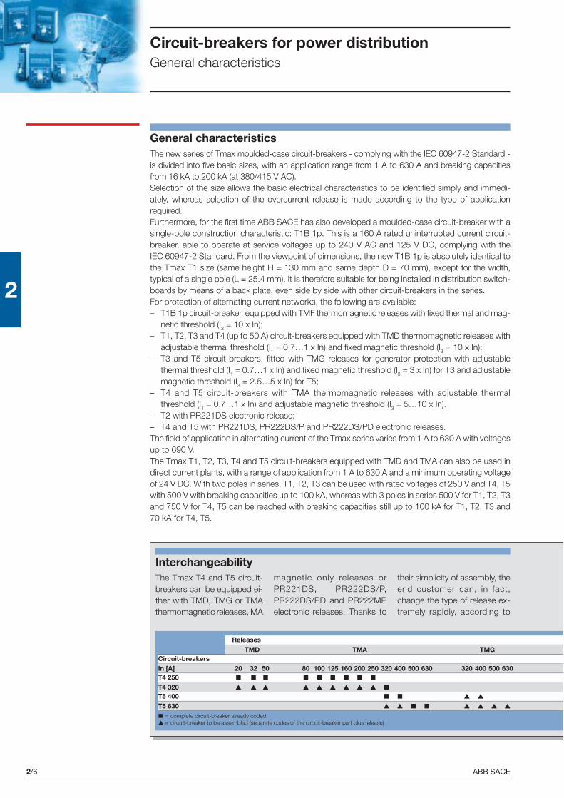
ABB SACE2/6
2
Circuit-breakers for power distributionGeneral characteristics
General characteristicsThe new series of Tmax moulded-case circuit-breakers - complying with the IEC 60947-2 Standard -is divided into five basic sizes, with an application range from 1 A to 630 A and breaking capacitiesfrom 16 kA to 200 kA (at 380/415 V AC).Selection of the size allows the basic electrical characteristics to be identified simply and immedi-ately, whereas selection of the overcurrent release is made according to the type of applicationrequired.Furthermore, for the first time ABB SACE has also developed a moulded-case circuit-breaker with asingle-pole construction characteristic: T1B 1p. This is a 160 A rated uninterrupted current circuit-breaker, able to operate at service voltages up to 240 V AC and 125 V DC, complying with theIEC 60947-2 Standard. From the viewpoint of dimensions, the new T1B 1p is absolutely identical tothe Tmax T1 size (same height H = 130 mm and same depth D = 70 mm), except for the width,typical of a single pole (L = 25.4 mm). It is therefore suitable for being installed in distribution switch-boards by means of a back plate, even side by side with other circuit-breakers in the series.For protection of alternating current networks, the following are available:– T1B 1p circuit-breaker, equipped with TMF thermomagnetic releases with fixed thermal and mag-
netic threshold (I3 = 10 x In);– T1, T2, T3 and T4 (up to 50 A) circuit-breakers equipped with TMD thermomagnetic releases with
adjustable thermal threshold (I1 = 0.7…1 x In) and fixed magnetic threshold (I3 = 10 x In);– T3 and T5 circuit-breakers, fitted with TMG releases for generator protection with adjustable
thermal threshold (I1 = 0.7…1 x In) and fixed magnetic threshold (I3 = 3 x In) for T3 and adjustablemagnetic threshold (I3 = 2.5…5 x In) for T5;
– T4 and T5 circuit-breakers with TMA thermomagnetic releases with adjustable thermalthreshold (I1 = 0.7…1 x In) and adjustable magnetic threshold (I3 = 5…10 x In).
– T2 with PR221DS electronic release;– T4 and T5 with PR221DS, PR222DS/P and PR222DS/PD electronic releases.The field of application in alternating current of the Tmax series varies from 1 A to 630 A with voltagesup to 690 V.The Tmax T1, T2, T3, T4 and T5 circuit-breakers equipped with TMD and TMA can also be used indirect current plants, with a range of application from 1 A to 630 A and a minimum operating voltageof 24 V DC. With two poles in series, T1, T2, T3 can be used with rated voltages of 250 V and T4, T5with 500 V with breaking capacities up to 100 kA, whereas with 3 poles in series 500 V for T1, T2, T3and 750 V for T4, T5 can be reached with breaking capacities still up to 100 kA for T1, T2, T3 and70 kA for T4, T5.
■ = complete circuit-breaker already coded▲ = circuit-breaker to be assembled (separate codes of the circuit-breaker part plus release)
ReleasesTMD TMA TMG
Circuit-breakersIn [A] 20 32 50 80 100 125 160 200 250 320 400 500 630 320 400 500 630T4 250 ■ ■ ■ ■ ■ ■ ■ ■ ■
T4 320 ▲ ▲ ▲ ▲ ▲ ▲ ▲ ▲ ▲ ■
T5 400 ■ ■ ▲ ▲
T5 630 ▲ ▲ ■ ■ ▲ ▲ ▲ ▲
InterchangeabilityThe Tmax T4 and T5 circuit-breakers can be equipped ei-ther with TMD, TMG or TMAthermomagnetic releases, MA
magnetic only releases orPR221DS, PR222DS/P,PR222DS/PD and PR222MPelectronic releases. Thanks to
their simplicity of assembly, theend customer can, in fact,change the type of release ex-tremely rapidly, according to
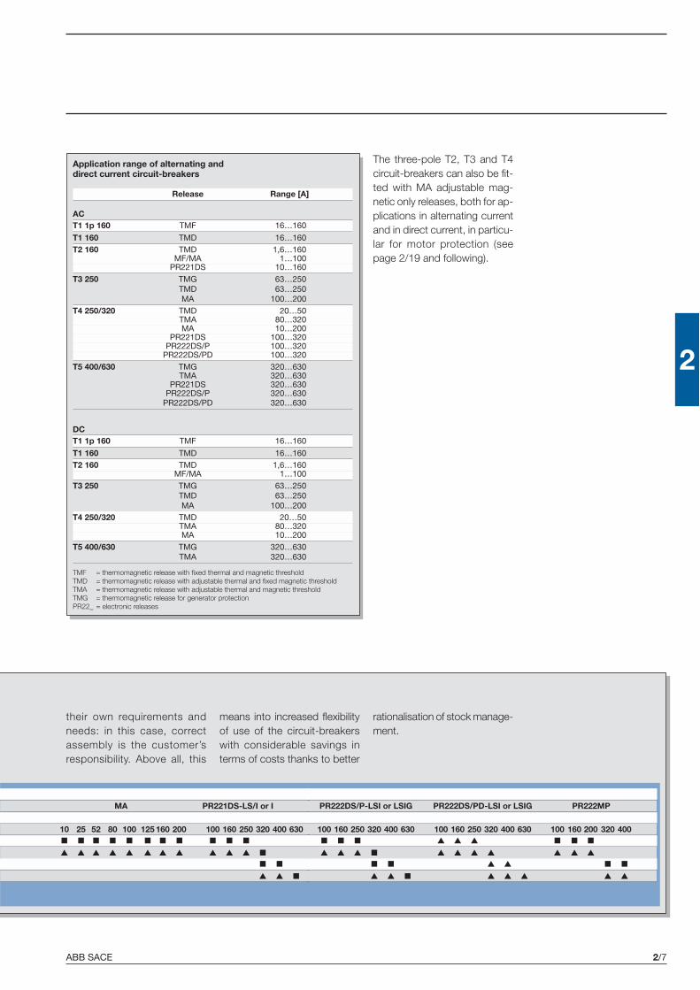
ABB SACE 2/7
2
Application range of alternating anddirect current circuit-breakers
Release Range [A]
ACT1 1p 160 TMF 16…160
T1 160 TMD 16…160T2 160 TMD 1,6…160
MF/MA 1…100PR221DS 10…160
T3 250 TMG 63…250TMD 63…250MA 100…200
T4 250/320 TMD 20…50TMA 80…320MA 10…200
PR221DS 100…320PR222DS/P 100…320
PR222DS/PD 100…320T5 400/630 TMG 320…630
TMA 320…630PR221DS 320…630
PR222DS/P 320…630PR222DS/PD 320…630
DCT1 1p 160 TMF 16…160
T1 160 TMD 16…160T2 160 TMD 1,6…160
MF/MA 1…100T3 250 TMG 63…250
TMD 63…250MA 100…200
T4 250/320 TMD 20…50TMA 80…320MA 10…200
T5 400/630 TMG 320…630TMA 320…630
TMF = thermomagnetic release with fixed thermal and magnetic thresholdTMD = thermomagnetic release with adjustable thermal and fixed magnetic thresholdTMA = thermomagnetic release with adjustable thermal and magnetic thresholdTMG = thermomagnetic release for generator protectionPR22_ = electronic releases
PR222DS/P-LSI or LSIG PR222DS/PD-LSI or LSIG PR222MP
100 160 250 320 400 630 100 160 250 320 400 630 100 160 200 320 400■ ■ ■ ▲ ▲ ▲ ■ ■ ■
▲ ▲ ▲ ■ ▲ ▲ ▲ ▲ ▲ ▲ ▲
■ ■ ▲ ▲ ■ ■
▲ ▲ ■ ▲ ▲ ▲ ▲ ▲
MA PR221DS-LS/I or I
10 25 52 80 100 125 160 200 100 160 250 320 400 630■ ■ ■ ■ ■ ■ ■ ■ ■ ■ ■
▲ ▲ ▲ ▲ ▲ ▲ ▲ ▲ ▲ ▲ ▲ ■
■ ■
▲ ▲ ■
The three-pole T2, T3 and T4circuit-breakers can also be fit-ted with MA adjustable mag-netic only releases, both for ap-plications in alternating currentand in direct current, in particu-lar for motor protection (seepage 2/19 and following).
their own requirements andneeds: in this case, correctassembly is the customer’sresponsibility. Above all, this
means into increased flexibilityof use of the circuit-breakerswith considerable savings interms of costs thanks to better
rationalisation of stock manage-ment.

ABB SACE2/8
2
1SD
C21
0313
F000
41S
DC
2103
14F0
004
Circuit-breakers for power distributionThermomagnetic releases
Thermomagnetic releasesThe Tmax T1 1p, T1, T2, T3, T4 and T5 circuit-breakers can befitted with thermomagnetic releases and are used in protection ofalternating and direct current networks with a range of use from1,6 A to 630 A. They allow the protection against overload with athermal device (with fixed threshold for T1 1p and adjustable thresh-old for T1, T2, T3, T4 and T5) realised using the bimetal tech-nique, and protection against short-circuit with a magnetic device(with fixed threshold for T1, T2 and T3 and T4 up to 50 A andadjustable threshold for T4 and T5).The four-pole circuit-breakers are always supplied with the neutralprotected by the release and with protection of the neutral at 100%of the phase setting for settings up to 100 A. For higher settings,the version with protection of the neutral at 50% of the phasesetting is also available.Furthermore, for Tmax T3 and T5, the TMG thermomagneticreleases for generator protection are available. For T3 the releasehas adjustable thermal threshold (I1 = 0.7…1 x In) and fixedmagnetic threshold (I3 = 3 x In), whereas for T5 the release hasadjustable thermal threshold (I1 = 0.7…1 x In) and adjustablemagnetic threshold (I3 = 2.5… 5 x In).
Thermomagnetic release TMD and TMG (for T3)
TMD = thermomagnetic release with adjustable thermal threshold (I1 = 0,7…1 x In) and magnetic fixed threshold.TMG (for T3) = thermomagnetic release for generator protection with adjustable thermal threshold (I1 = 0.7…1 x In) and fixed magnetic threshold
Thermal thresholdAdjustable from 0.7 to 1 x In
Thermal thresholdAdjustable from 0.7 to 1 x In

ABB SACE 2/9
2
TMD - T2
TMG - T3
1SD
C21
0186
F000
4
T1 160
T3 250
I3 = 10 x In
I1= In
In [A] 16 20 25 32 40 50 63 80 100 125 160
I3 [A] 500 500 500 500 500 500 630 800 1000 1250 1600
In [A] 16 20 25 32 40 50 63 80 100 125 125 160 200 250
Neutral [A] - 100% 16 20 25 32 40 50 63 80 100 125 - 160 200 250
Neutral [A] - 50% - - - - - - - - - - 80 100 125 160
■ ■ ■ ■ ■ ■ ■ ■ ■ ■ - ■ - -
■ ■ ■ ■ ■ ■ ■ ■
I3 [A] 500 500 500 500 500 500 630 800 1000 1250 1250 1600 2000 2500
Neutral [A] - 100% 500 500 500 500 500 500 630 800 1000 1250 - 1600 2000 2500
Neutral [A] - 50% - - - - - - - - - - 800 1000 1250 1600I3 = 10 x In
I1=0.7…1 x In
I3 = 10 x In
I1=0.7…1 x In
In [A] 1.6 2 2.5 3.2 4 5 6.3 8 10 12.5 16 20 25 32 40 50 63 80 100 125 160
Neutral [A] - 100% 1.6 2 2.5 3.2 4 5 6.3 8 10 12.5 16 20 25 32 40 50 63 80 100 125 160
Neutral [A] - 50% - - - - - - - - - - - - - - - - - - - 80 100
I3 [A] 16 20 25 32 40 50 63 80 100 125 500 500 500 500 500 500 630 800 1000 1250 1600
Neutral [A] - 100% 16 20 25 32 40 50 63 80 100 125 500 500 500 500 500 500 630 800 1000 1250 1600
Neutral [A] - 50% - - - - - - - - - - - - - - - - - - - 800 1000
Thermomagnetic release TMF for T1B 1p
Notes:– In identifies the setting current for protection of the phases (L1, L2 and L3) and of the neutral.– The TMD and TMA thermomagnetic releases have the thermal element with adjustable threshold I1 = 0.7…1 x In. The value of the thermal element adjustment which is obtained by acting on the
special selector, is intended at 40 °C. The magnetic element has fixed trip threshold with ± 20% tolerance according to what is indicated by the IEC 60947-2 (pos. 8.3.3.1.2) Standard. The tripthresholds of the magnetic protection I3 are a function of the setting used both by the phase and neutral protection.
I3 = 3 x In
I1=0.7…1 x In
TMF = thermomagnetic release with fixed thermal and magnetic threshold.
TMD - T1 and T3
TMF - T1 1p
In [A] 63 80 100 125 160 200 250
Neutral [A] - 100% 63 80 100 125 160 200 250
I3 [A] 400 400 400 400 480 600 750
Neutral [A] - 100% 400 400 400 400 480 600 750
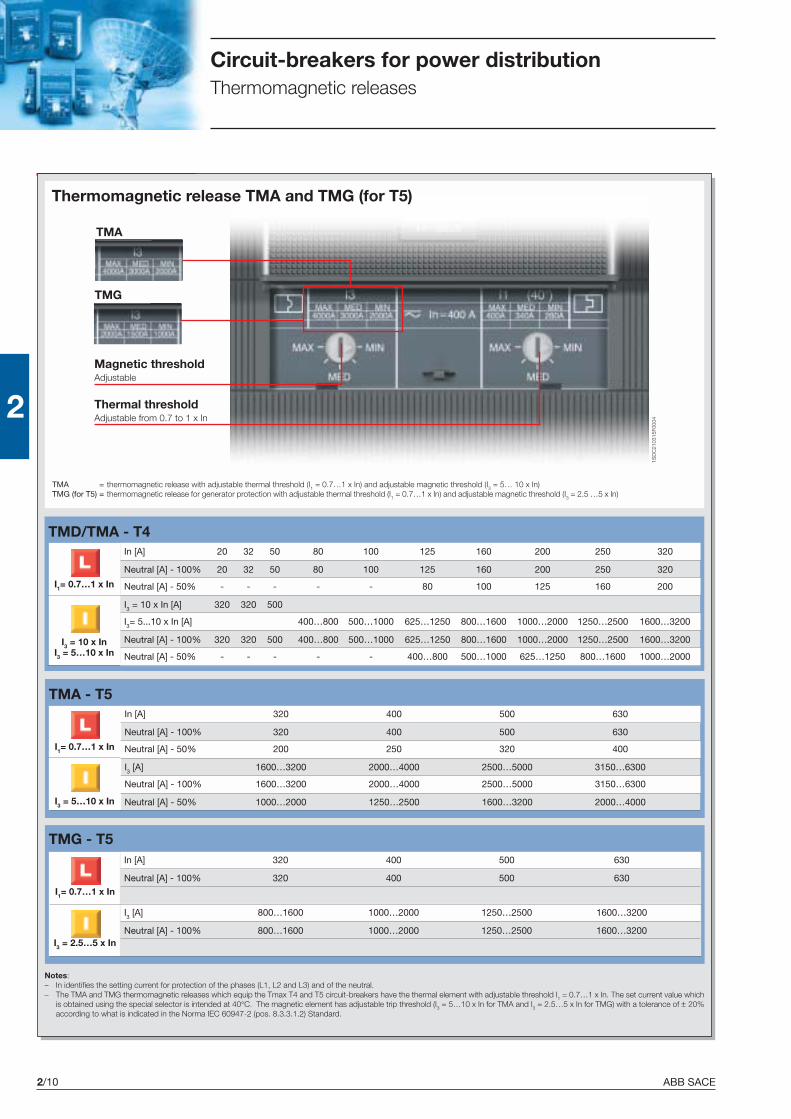
ABB SACE2/10
2
TMD/TMA - T4
TMA - T5
TMG - T5
1SD
C21
0315
F000
4
TMA
TMG
Circuit-breakers for power distributionThermomagnetic releases
In [A] 20 32 50 80 100 125 160 200 250 320
Neutral [A] - 100% 20 32 50 80 100 125 160 200 250 320
Neutral [A] - 50% - - - - - 80 100 125 160 200
I3 = 10 x In [A] 320 320 500
I3= 5...10 x In [A] 400…800 500…1000 625…1250 800…1600 1000…2000 1250…2500 1600…3200
Neutral [A] - 100% 320 320 500 400…800 500…1000 625…1250 800…1600 1000…2000 1250…2500 1600…3200
Neutral [A] - 50% - - - - - 400…800 500…1000 625…1250 800…1600 1000…2000
I3 = 10 x InI3 = 5…10 x In
I1= 0.7…1 x In
In [A] 320 400 500 630
Neutral [A] - 100% 320 400 500 630
Neutral [A] - 50% 200 250 320 400
I3 [A] 1600…3200 2000…4000 2500…5000 3150…6300
Neutral [A] - 100% 1600…3200 2000…4000 2500…5000 3150…6300
Neutral [A] - 50% 1000…2000 1250…2500 1600…3200 2000…4000
I1= 0.7…1 x In
I3 = 5…10 x In
Thermomagnetic release TMA and TMG (for T5)
Notes:– In identifies the setting current for protection of the phases (L1, L2 and L3) and of the neutral.– The TMA and TMG thermomagnetic releases which equip the Tmax T4 and T5 circuit-breakers have the thermal element with adjustable threshold I1 = 0.7…1 x In. The set current value which
is obtained using the special selector is intended at 40°C. The magnetic element has adjustable trip threshold (I3 = 5…10 x In for TMA and I3 = 2.5…5 x In for TMG) with a tolerance of ± 20%according to what is indicated in the Norma IEC 60947-2 (pos. 8.3.3.1.2) Standard.
TMA = thermomagnetic release with adjustable thermal threshold (I1 = 0.7…1 x In) and adjustable magnetic threshold (I3 = 5… 10 x In)TMG (for T5) = thermomagnetic release for generator protection with adjustable thermal threshold (I1 = 0.7…1 x In) and adjustable magnetic threshold (I3 = 2.5 …5 x In)
I3 = 2.5…5 x In
I1= 0.7…1 x In
In [A] 320 400 500 630
Neutral [A] - 100% 320 400 500 630
I3 [A] 800…1600 1000…2000 1250…2500 1600…3200
Neutral [A] - 100% 800…1600 1000…2000 1250…2500 1600…3200
Thermal thresholdAdjustable from 0.7 to 1 x In
Magnetic thresholdAdjustable
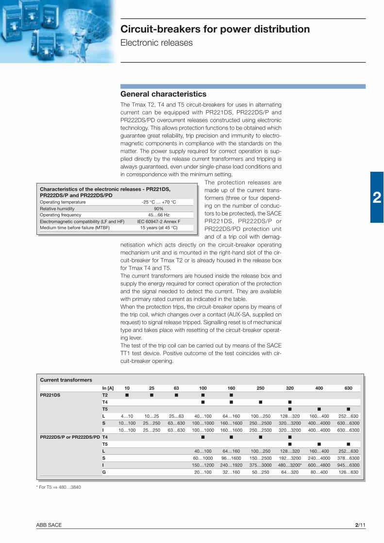
ABB SACE 2/11
2
General characteristicsThe Tmax T2, T4 and T5 circuit-breakers for uses in alternatingcurrent can be equipped with PR221DS, PR222DS/P andPR222DS/PD overcurrent releases constructed using electronictechnology. This allows protection functions to be obtained whichguarantee great reliability, trip precision and immunity to electro-magnetic components in compliance with the standards on thematter. The power supply required for correct operation is sup-plied directly by the release current transformers and tripping isalways guaranteed, even under single-phase load conditions andin correspondence with the minimum setting.
Circuit-breakers for power distributionElectronic releases
The protection releases aremade up of the current trans-formers (three or four depend-ing on the number of conduc-tors to be protected), the SACEPR221DS, PR222DS/P orPR222DS/PD protection unitand of a trip coil with demag-
netisation which acts directly on the circuit-breaker operatingmechanism unit and is mounted in the right-hand slot of the cir-cuit-breaker for Tmax T2 or is already housed in the release boxfor Tmax T4 and T5.The current transformers are housed inside the release box andsupply the energy required for correct operation of the protectionand the signal needed to detect the current. They are availablewith primary rated current as indicated in the table.When the protection trips, the circuit-breaker opens by means ofthe trip coil, which changes over a contact (AUX-SA, supplied onrequest) to signal release tripped. Signalling reset is of mechanicaltype and takes place with resetting of the circuit-breaker operat-ing lever.The test of the trip coil can be carried out by means of the SACETT1 test device. Positive outcome of the test coincides with cir-cuit-breaker opening.
Characteristics of the electronic releases - PR221DS,PR222DS/P and PR222DS/PDOperating temperature -25 °C … +70 °CRelative humidity 90%Operating frequency 45…66 Hz
Electromagnetic compatibility (LF and HF) IEC 60947-2 Annex FMedium time before failure (MTBF) 15 years (at 45 °C)
Current transformers
In [A] 10 25 63 100 160 250 320 400 630
PR221DS T2 ■ ■ ■ ■ ■
T4 ■ ■ ■ ■
T5 ■ ■ ■
L 4…10 10…25 25…63 40…100 64…160 100…250 128…320 160…400 252…630
S 10…100 25…250 63…630 100…1000 160…1600 250…2500 320…3200 400…4000 630…6300
I 10…100 25…250 63…630 100…1000 160…1600 250…2500 320…3200 400…4000 630…6300
PR222DS/P or PR222DS/PD T4 ■ ■ ■ ■
T5 ■ ■ ■
L 40…100 64…160 100…250 128…320 160…400 252…630
S 60…1000 96…1600 150…2500 192…3200 240…4000 378…6300
I 150…1200 240…1920 375…3000 480…3200* 600…4800 945…6300
G 20…100 32…160 50…250 64…320 80…400 126…630
* For T5 ⇒ 480…3840
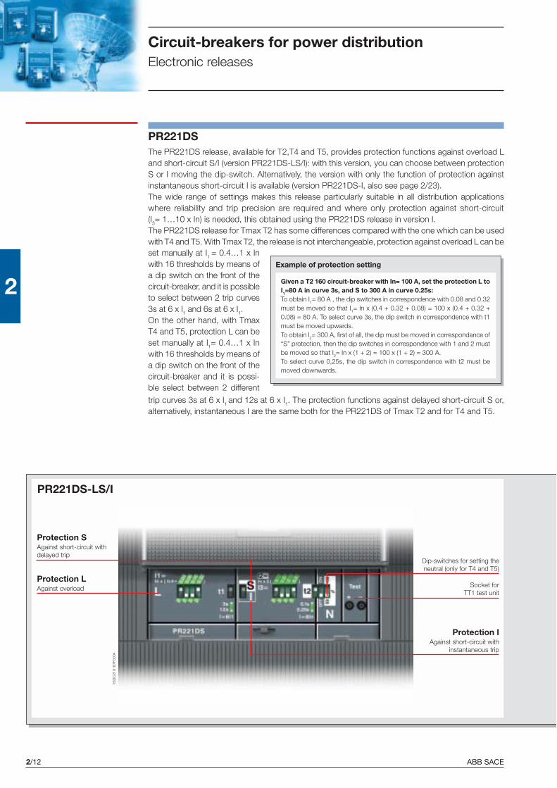
ABB SACE2/12
2
1SD
C21
0187
F000
4
Circuit-breakers for power distributionElectronic releases
Protection LAgainst overload
Protection SAgainst short-circuit withdelayed trip
Protection IAgainst short-circuit with
instantaneous trip
Socket forTT1 test unit
PR221DSThe PR221DS release, available for T2,T4 and T5, provides protection functions against overload Land short-circuit S/I (version PR221DS-LS/I): with this version, you can choose between protectionS or I moving the dip-switch. Alternatively, the version with only the function of protection againstinstantaneous short-circuit I is available (version PR221DS-I, also see page 2/23).The wide range of settings makes this release particularly suitable in all distribution applicationswhere reliability and trip precision are required and where only protection against short-circuit(I3= 1…10 x In) is needed, this obtained using the PR221DS release in version I.The PR221DS release for Tmax T2 has some differences compared with the one which can be usedwith T4 and T5. With Tmax T2, the release is not interchangeable, protection against overload L can be
Given a T2 160 circuit-breaker with In= 100 A, set the protection L toI1=80 A in curve 3s, and S to 300 A in curve 0.25s:To obtain I1= 80 A , the dip switches in correspondence with 0.08 and 0.32must be moved so that I1= In x (0.4 + 0.32 + 0.08) = 100 x (0.4 + 0.32 +0.08) = 80 A. To select curve 3s, the dip switch in correspondence with t1must be moved upwards.To obtain I2= 300 A, first of all, the dip must be moved in correspondance of“S” protection, then the dip switches in correspondence with 1 and 2 mustbe moved so that I2= In x (1 + 2) = 100 x (1 + 2) = 300 A.To select curve 0,25s, the dip switch in correspondence with t2 must bemoved downwards.
Example of protection setting
set manually at I1 = 0.4…1 x Inwith 16 thresholds by means ofa dip switch on the front of thecircuit-breaker, and it is possibleto select between 2 trip curves3s at 6 x I1 and 6s at 6 x I1.On the other hand, with TmaxT4 and T5, protection L can beset manually at I1= 0.4…1 x Inwith 16 thresholds by means ofa dip switch on the front of thecircuit-breaker and it is possi-ble select between 2 different
PR221DS-LS/I
trip curves 3s at 6 x I1 and 12s at 6 x I1. The protection functions against delayed short-circuit S or,alternatively, instantaneous I are the same both for the PR221DS of Tmax T2 and for T4 and T5.
Dip-switches for setting theneutral (only for T4 and T5)
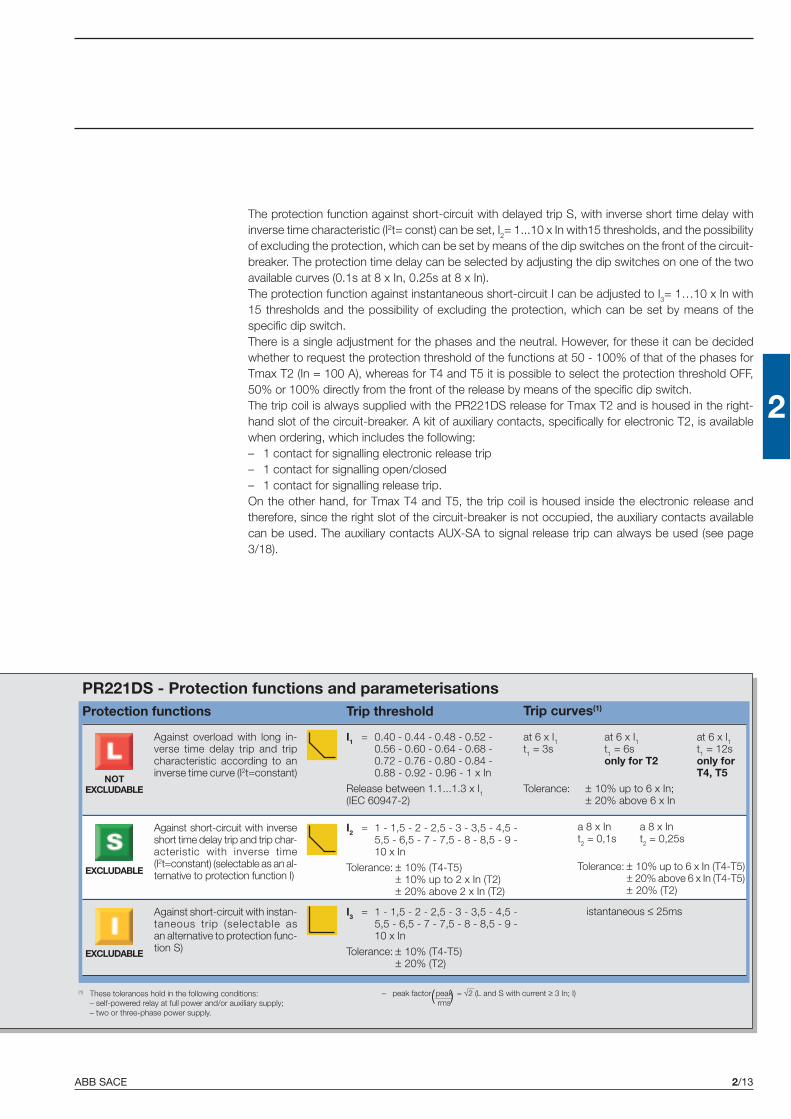
ABB SACE 2/13
2
PR221DS - Protection functions and parameterisationsProtection functions Trip threshold Trip curves(1)
Against overload with long in-verse time delay trip and tripcharacteristic according to aninverse time curve (I2t=constant)
I1 = 0.40 - 0.44 - 0.48 - 0.52 -0.56 - 0.60 - 0.64 - 0.68 -0.72 - 0.76 - 0.80 - 0.84 -0.88 - 0.92 - 0.96 - 1 x In
Release between 1.1...1.3 x I1(IEC 60947-2)
at 6 x I1 at 6 x I1 at 6 x I1t1 = 3s t1 = 6s t1 = 12s
only for T2 only forT4, T5
Tolerance: ± 10% up to 6 x In;± 20% above 6 x In
NOTEXCLUDABLE
EXCLUDABLE
EXCLUDABLE
Against short-circuit with instan-taneous trip (selectable asan alternative to protection func-tion S)
Against short-circuit with inverseshort time delay trip and trip char-acteristic with inverse time(I2t=constant) (selectable as an al-ternative to protection function I)
The protection function against short-circuit with delayed trip S, with inverse short time delay withinverse time characteristic (I2t= const) can be set, I2= 1...10 x In with15 thresholds, and the possibilityof excluding the protection, which can be set by means of the dip switches on the front of the circuit-breaker. The protection time delay can be selected by adjusting the dip switches on one of the twoavailable curves (0.1s at 8 x In, 0.25s at 8 x In).The protection function against instantaneous short-circuit I can be adjusted to I3= 1…10 x In with15 thresholds and the possibility of excluding the protection, which can be set by means of thespecific dip switch.There is a single adjustment for the phases and the neutral. However, for these it can be decidedwhether to request the protection threshold of the functions at 50 - 100% of that of the phases forTmax T2 (In = 100 A), whereas for T4 and T5 it is possible to select the protection threshold OFF,50% or 100% directly from the front of the release by means of the specific dip switch.The trip coil is always supplied with the PR221DS release for Tmax T2 and is housed in the right-hand slot of the circuit-breaker. A kit of auxiliary contacts, specifically for electronic T2, is availablewhen ordering, which includes the following:– 1 contact for signalling electronic release trip– 1 contact for signalling open/closed– 1 contact for signalling release trip.On the other hand, for Tmax T4 and T5, the trip coil is housed inside the electronic release andtherefore, since the right slot of the circuit-breaker is not occupied, the auxiliary contacts availablecan be used. The auxiliary contacts AUX-SA to signal release trip can always be used (see page3/18).
(1) These tolerances hold in the following conditions:– self-powered relay at full power and/or auxiliary supply;– two or three-phase power supply.
istantaneous ≤ 25ms
I2 = 1 - 1,5 - 2 - 2,5 - 3 - 3,5 - 4,5 -5,5 - 6,5 - 7 - 7,5 - 8 - 8,5 - 9 -10 x In
Tolerance: ± 10% (T4-T5)± 10% up to 2 x In (T2)± 20% above 2 x In (T2)
I3 = 1 - 1,5 - 2 - 2,5 - 3 - 3,5 - 4,5 -5,5 - 6,5 - 7 - 7,5 - 8 - 8,5 - 9 -10 x In
Tolerance: ± 10% (T4-T5)± 20% (T2)
a 8 x In a 8 x Int2 = 0,1s t2 = 0,25s
Tolerance: ± 10% up to 6 x In (T4-T5)± 20% above 6 x In (T4-T5)± 20% (T2)
– peak factor peak = √2 (L and S with current ≥ 3 In; I)rms
( )

ABB SACE2/14
2
PR222DS/PThe PR222DS/P release, avail-able for T4 and T5, has protec-tion functions against overloadL, delayed S and instantaneousI short-circuit (versionPR222DS/P-LSI) and, alterna-tively, as well as the functionsL, S, I, also has protectionagainst earth fault G (versionPR222DS/P-LSIG).The wide range of adjustmentsmakes this release particularlysuitable in all distribution appli-cations where reliability and tripprecision are required.Function L, which cannot beexcluded, can be set manuallyto I1= 0.4…1 x In with 32 thresh-olds which can be set by meansof the dip switches on the frontof the release, or electronicallyby means of the SACE PR010Ttest and configuration unitwhich can be set betweenI1= 0.4…1 x In with 61 thresh-olds (steps of 0.01 x In). Further-more, it is possible to selectamong four different trip curves:3s at 6 x I1, 6s at 6 x I1, 9s at6 x I1, 12s at 6 x In for T4In = 320 A and T5 In = 630 Aand 18s at 6 x I1 for all the othersettings.Otherwise it is also possible toset the trip time to 6 x I1 elec-tronically between 3 and 18swith 31 thresholds (step of 0.5s),except for T4 In= 320 A and T5In= 630 A, for which the maxi-mum value is 12s.
Circuit-breakers for power distributionElectronic releases
The function of protectionagainst short-circuit with de-layed trip S, with inverse shortdelay with characteristic withinverse time (I2t = cost) or withdefinite time, can be set toI2 = 0.6…10 x In with 15 thresh-olds and the possibility of ex-cluding the protection, whichcan be set by means of the dipswitches on the front of the cir-cuit-breaker, or with the SACEPR010T I2 = 0.6…10 x In with95 thresholds (steps of 0.1). Thetime delay of the protection canbe selected either manually byadjusting the dip switch to oneof the four curves available(with delay of 0.05s at 8 x In,0.1s at 8 x In, 0.25s at 8 x In or0.5s at 8 x In) or electronicallyby means of PR010T between0.05 and 0.5s at 8 x In with46 thresholds (steps of 0.01s).The function of protectionagainst instantaneous short-circuit I is adjustable toI3
(1) = 1.5…12 x In with 15thresholds and the possibility ofexcluding the protection, can beset by means of dip switches,or with the SACE PR010T atI3
(1) = 1.5…12 x In with 86thresholds (steps of 0.1 x In).The function of protectionagainst earth fault G is adjust-able either manually, by meansof dip switches, to I4 = 0.2…1 xIn with 7 thresholds and thepossibility of excluding the pro-
tection, or electronically bymeans of the SACE PR010T toI4 = 0.2…1 x In with 81 thresh-olds (steps of 0.01 x In). It is alsopossible to select among fourdifferent trip curves: 0.1s at3.15 x I4, 0.2s at 2.25 x I4,0.4s at 1.6 x I4 and 0.8s at1.10 x I4, or to set the trip timeelectronically between 0.1 and0.8s with 71 thresholds (stepsof 0.01s).There is a single setting for thephases and neutral, for whichone can decide whether to setthe threshold of the protectionfunctions to OFF, to 50% orto100% that of the phases bymeans of two special dipswitches on the front of the cir-cuit-breaker.Furthermore, on the front of thePR222DS/P (or PD) releases,signalling of pre-alarm andalarm of protection L is available.The pre-alarm threshold value(cannot be excluded or modi-fied by the user) is equal to0.9 x I1. It is also possible totransmit remotely the alarm ofprotection L, simply connectingconnector X3 to the dedicatedcontact.
(1) For T4 In = 320 A and T5 In = 630 A ⇒ I3max = 10 x In

ABB SACE 2/15
2
PR222DS/PDApart from the protection func-tions against overload L, de-layed S and instantaneous Ishort-circuit (version PR222DS/PD-LSI) or, alternatively, plus the
extra protection against earthfault G (version PR222DS/PD-LSIG), the PR222DS/PD re-lease, available for T4 and T5,also has the dialogue unit inte-grated with Modbus® RTU pro-tocol.The Modbus® RTU protocol hasbeen known and used world-wide for many years and is nowa market standard thanks to itssimplicity of installation, configu-ration and to its integration in thevarious different supervision,control and automation sys-tems, as well as good level per-formances.The PR222/PD releases allowthe Tmax T4 and T5 circuit-breakers to be integrated in acommunication network basedon the Modbus® RTU protocol.Modbus® RTU provides a Mas-ter-Slave system architecturewhere a Master (PLC, PC…)cyclically interrogates severalSlaves (field devices). The de-vices use the EIA RS485 stand-ard as the physical means fordata transmission at a maxi-mum transmission speed of19200 bit/sec.Again for this release, the powersupply needed for correct op-eration of the protection func-tions is supplied directly by thecurrent transformers of the re-lease, and tripping is alwaysguaranteed, even under condi-tions of single-phase load andin correspondence with theminimum setting. Nevertheless,communication is only possiblewith an auxiliary power supplyof 24 V DC.The PR222DS/PD release, withintegrated communication and
control functions, allows a widerange of information to be ac-quired and transmitted remotely,to carry out opening and clos-ing commands thanks to shuntopening and closing releases in-stalled on board the circuit-breaker, to store the configura-tion parameters and those forprogramming the unit itself likethe current thresholds of theprotection functions and theprotection curves.All the information can be con-sulted both locally, directly onthe front of the circuit-breakerwith the front display unit FDU,and remotely by means of su-pervision and control systems.The PR222DS/PD releases canbe associated with the AUX-Eauxiliary contacts in electronicversion, to know the state of thecircuit-breaker (open/closed),and with AUX-E plus MOE-Emotor operator (the AUX-E arecompulsory when MOE-E is tobe used) to remotely control cir-cuit-breaker opening and clos-ing as well (also see page 3/17and following).If the circuit-breaker fitted withthe PR222DS/PD release is in-serted in a supervision system,during the test phases with thePR010/T unit, communication isautomatically abandoned andstarts again on completion ofthis operation.Communication towards the dis-play unit FDU is also available,which can also take place withself-supply starting from 0.35 xIn present at least on one phase.The details of the functionsavailable are indicated in the dia-gram.
Communication functions PR222DS/P PR222DS/PDProtocol Modbus RTU
standardPhysical medium EIA RS485
Speed (maximum) 19200bpsMeasurement functionsPhase currents ■ (1) ■
Neutral ■ (1) ■
Earth ■ (1) ■
Signalling functionsL pre-alarm and alarm LED ■ ■
L alarm output contact (2) ■ ■
Data availableState of the circuit-breaker (open, closed) ■
Mode (local, remote) ■
Protection parameters set ■ (1) ■
AlarmsProtections: L, S, I, G ■ (1) ■
Release control for failed fault ■ (1) ■
MaintenanceTotal number of operations ■
Total number of trips ■
Number of trip tests ■
Number of manual operations ■
Number of trips for each individualprotection function ■
Record of last trip data ■
CommandsCircuit-breaker opening/closing(with motor operator) ■
Alarm reset ■
Circuit-breaker reset (with motor operator) ■
Setting the protection curves and thresholds ■ (1) ■
Safety functionAutomatic opening in the case of failedrelease for fault (with motor operator) ■
EventsChanges in circuit-breaker state,in the protections and all the alarams ■
(1) With PR010/T unit(2) Typical contact: MOS photo Vmax: 48 V DC/30 V AC
Imax: 50 mA DC/35 mA AC
Auxiliary power supply - Electrical characteristics
PR222DS/PDAuxiliary power supply (galvanically insulated) 24 V DC ± 20%
Maximum ripple 5%
Inrush current @ 24 V 1 A for 30 ms
Rated current @ 24 V 100 mA
Rated power @ 24 V 2,5 W

ABB SACE2/16
2
1SD
C21
0188
F000
41S
DC
2101
89F0
004
Circuit-breakers for power distributionElectronic releases
PR222DS/PD
PR222DS/P
Protection LAgainst overload
Protection GAgainst earth fault
Dip-switches forsetting the neutral
Selection for electronicor manual setting
Socket for testSACE TT1 test unit
Socket for connection ofSACE PR010/T test unit
Protection LAgainst overload
Protection GAgainst earth fault
Dip-switches forsetting the neutral
Selection for localor remote setting
Socket for testSACE TT1 test unit
Socket for connection ofSACE PR010/T test unit
Protection SAgainst short-circuitwith delayed trip
Protection IAgainst short-circuit
with instantaneous trip
Protection SAgainst short-circuitwith delayed trip
Protection IAgainst short-circuit
with instantaneous trip
Selection for electronicor manual setting
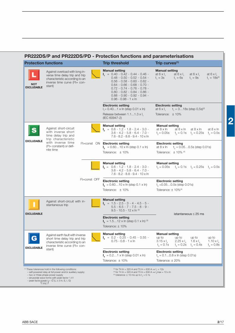
ABB SACE 2/17
2
PR222DS/P and PR222DS/PD - Protection functions and parameterisationsProtection functions Trip threshold Trip curves(1)
Against overload with long in-verse time delay trip and tripcharacteristic according to aninverse time curve (I2t= con-stant)
Manual settingI3 = 1.5 - 2.5 - 3 - 4 - 4.5 - 5 -
5.5 - 6.5 - 7 - 7.5 - 8 - 9 -9.5 - 10.5 - 12 x In (3)
Electronic settingI3 = 1.5…12 x In (step 0.1 x In) (3)
Tolerance: ± 10%
NOTEXCLUDABLE
EXCLUDABLE
EXCLUDABLE
Against short-circuit with in-stantaneous trip
Against short-circuitwith inverse shorttime delay trip andtrip characteristicwith inverse time(I2t= constant) or defi-nite time
Manual settingI4 = 0.2 - 0.25 - 0.45 - 0.55 -
0.75 - 0.8 - 1 x In
Electronic settingI4 = 0.2…1 x In (step 0.01 x In)
Tolerance: ± 10%
EXCLUDABLE
Against earth fault with inverseshort time delay trip and tripcharacteristic according to aninverse time curve (I2t= con-stant)
(1) These tolerances hold in the following conditions:– self-powered relay at full power and/or auxiliary supply;– two or three-phase power supply– sinusoidal wave forms with peak factor 1.41– peak factor peak = √2 (L ≥ 3 In; S, I, G)
rms
Manual settingI1 = 0.40 - 0.42 - 0.44 - 0.46 -
0.48 - 0.50 - 0.52 - 0.54 -0.56 - 0.58 - 0.60 - 0.62 -0.64 - 0.66 - 0.68 - 0.70 -0.72 - 0.74 - 0.76 - 0.78 -0.80 - 0.82 - 0.84 - 0.86 -0.88 - 0.90 - 0.92 - 0.94 -0.96 - 0.98 - 1 x In
Electronic settingI1= 0.40…1 x In (step 0.01 x In)
Release between 1.1...1.3 x I1(IEC 60947-2)
Manual settingat 6 x I1 at 6 x I1 at 6 x I1 at 6 x I1t1 = 3s t1 = 6s t1 = 9s t1 = 18s(2)
Electronic settingat 6 x I1 t1 = 3…18s (step 0,5s)(2)
Tolerance: ± 10%
Manual settingI2 = 0.6 - 1.2 - 1.8 - 2.4 - 3.0 -
3.6 - 4.2 - 5.8 - 6.4 - 7.0 -7.6 - 8.2 - 8.8 - 9.4 - 10 x In
Electronic settingI2 = 0.60…10 x In (step 0.1 x In)
Tolerance: ± 10%
Manual settingat 8 x In at 8 x In at 8 x In at 8 x Int2 = 0.05s t2 = 0.1s t2 = 0.25s t2 = 0.5s
Electronic settingat 8 x In t2 = 0.05…0.5s (step 0.01s)
Tolerance: ± 10% (4)
I2t=const ON
Manual settingI2 = 0.6 - 1.2 - 1.8 - 2.4 - 3.0 -
3.6 - 4.2 - 5.8 - 6.4 - 7.0 -7.6 - 8.2 - 8.8 - 9.4 - 10 x In
Electronic settingI2 = 0.60…10 x In (step 0.1 x In)
Tolerance: ± 10%
Manual settingt2 = 0.05s t2 = 0.1s t2 = 0.25s t2 = 0.5s
Electronic settingt2 =0.05…0.5s (step 0.01s)
Tolerance: ± 10%(4)
I2t=const OFF
Manual settingup to up to up to up to3.15 x I4 2.25 x I4 1.6 x I4 1.10 x I4 t4 = 0.1s t4 = 0.2s t4 = 0.4s t4 = 0.8s
Electronic settingt4 = 0.1...0.8 x In (step 0.01s)
Tolerance: ± 20%
istantaneous ≤ 25 ms
(2) for T4 In = 320 A and T5 In = 630 A ⇒ t1 = 12s(3) for T4 In = 320 A and T5 In = 630 A ⇒ I3max = 10 x In(4) tolerance: ± 10 ms up to t2 = 0.1s
( )


ABB SACE
2
2/19
Circuit-breakers for motorprotection
Index
Tmax circuit-breakers for motor protection
Electrical characteristics ...................................................................................................... 2/20
Protection against short-circuit ............................................................................................ 2/22
Integrated protection: PR222MP ......................................................................................... 2/24

ABB SACE2/20
2
Circuit-breakers for motor protectionElectrical characteristics
Tmax T2Rated uninterrupted current, Iu [A] 160
Rated service current, In [A] 1…100Poles [No.] 3
Rated service voltage, Ue (AC) 50-60 Hz [V] 690(DC) [V] 500
Rated impulse withstand voltage, Uimp [kV] 8Rated insulation voltage, Ui [V] 800
Test voltage at industrial frequency for 1 min. [V] 3000Rated ultimate short-circuit breaking capacity, Icu N S H L
(AC) 50-60 Hz 220/230 V [kA] 65 85 100 120(AC) 50-60 Hz 380/415 V [kA] 36 50 70 85
(AC) 50-60 Hz 440 V [kA] 30 45 55 75(AC) 50-60 Hz 500 V [kA] 25 30 36 50
(AC) 50-60 Hz 690 V [kA] 6 7 8 10Rated short-circuit service breaking capacity, Ics [%Icu]
(AC) 50-60 Hz 220/230 V [%Icu] 100% 100% 100% 100%(AC) 50-60 Hz 380/415 V [%Icu] 100% 100% 100% 75% (70 kA)
(AC) 50-60 Hz 440 V [%Icu] 100% 100% 100% 75%(AC) 50-60 Hz 500 V [%Icu] 100% 100% 100% 75%
(AC) 50-60 Hz 690 V [%Icu] 100% 100% 100% 75%Rated short-circuit making capacity, Icm [kA]
(AC) 50-60 Hz 220/230 V [kA] 143 187 220 264(AC) 50-60 Hz 380/415 V [kA] 75.6 105 154 187
(AC) 50-60 Hz 440 V [kA] 63 94.5 121 165(AC) 50-60 Hz 500 V [kA] 52.5 63 75.6 105
(AC) 50-60 Hz 690 V [kA] 9.2 11.9 13.6 17Opening time (415 V) [ms] 3 3 3 3
Category of use (EN 60947-2-1) AIsolation behaviour ■
Reference Standard IEC 60947-2Protection against short-circuit
Magnetic only release MA ■ (MF up to In 12.5 A)Electronic release PR221DS-I ■
Integrated protection (IEC 60947-4-1)Electronic release PR222MP –
Interchangeability –Versions F-P
Terminals fixed F - FC Cu - FC CuAl - EF -ES - R - FC CuAl
plug-in F - FC Cu - FC CuAl - EF -ES - R - FC CuAl
withdrawable –Fixing on DIN rail DIN EN 50022
Mechanical life [No. operations] 25000[No.hourly operations] 240
Electrical life @ 415 V AC [No. operations] 8000[No.hourly operations] 120
Basic fixed version dimensions L [mm] 90D [mm] 70
H [mm] 130Weight fixed [kg] 1.1
plug-in [kg] 1.5withdrawable [kg] –
TERMINAL CAPTIONF = FrontEF = Front extendedES = Front extended spreadFC Cu = Front for copper cablesR = Rear orientated
FC CuAl = Front for CuAl cablesMC = MulticableHR = Rear in horizontal flat barVR = Rear in vertical flat bar(*) Icw = 5 kA
(1) 75% for T5 630(2) 50% for T5 630
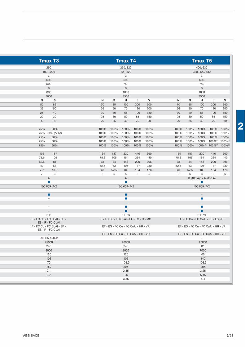
ABB SACE 2/21
2
Tmax T3 Tmax T4 Tmax T5250 250, 320 400, 630
100…200 10…320 320, 400, 6303 3 3
690 690 690500 750 750
8 8 8800 1000 1000
3000 3500 3500N S N S H L V N S H L V50 85 70 85 100 200 300 70 85 100 200 30036 50 36 50 70 120 200 36 50 70 120 200
25 40 30 40 65 100 180 30 40 65 100 18020 30 25 30 50 85 150 25 30 50 85 150
5 8 20 25 40 70 80 20 25 40 70 80
75% 50% 100% 100% 100% 100% 100% 100% 100% 100% 100% 100%75% 50% (27 kA) 100% 100% 100% 100% 100% 100% 100% 100% 100% 100%
75% 50% 100% 100% 100% 100% 100% 100% 100% 100% 100% 100%75% 50% 100% 100% 100% 100% 100% 100% 100% 100% 100%(1) 100%(2)
75% 50% 100% 100% 100% 100% 100% 100% 100% 100%(1) 100%(2) 100%(2)
105 187 154 187 220 440 660 154 187 220 440 66075.6 105 75.6 105 154 264 440 75.6 105 154 264 440
52.5 84 63 84 143 220 396 63 84 143 220 39640 63 52.5 63 105 187 330 52.5 63 105 187 330
7.7 13.6 40 52.5 84 154 176 40 52.5 84 154 1767 6 5 5 5 5 5 6 6 6 6 6
A A B (400 A)(*) - A (630 A)■ ■ ■
IEC 60947-2 IEC 60947-2 IEC 60947-2
■ ■ –– ■ ■
– ■ ■
– ■ ■
F-P F-P-W F-P-W
F - FC Cu - FC CuAl - EF - F - FC Cu - FC CuAl - EF - ES - R - MC F - FC Cu - FC CuAl - EF - ES - RES - R - FC CuAl
F - FC Cu - FC CuAl - EF - EF - ES - FC Cu - FC CuAl - HR - VR EF - ES - FC Cu - FC CuAl - HR - VRES - R - FC CuAl
– EF - ES - FC Cu - FC CuAl - HR - VR EF - ES - FC Cu - FC CuAl - HR - VRDIN EN 50022 – –
25000 20000 20000240 240 120
8000 8000 7000120 120 60
105 105 14070 103.5 103.5
150 205 2052.1 2.35 3.25
2.7 3.6 5.15– 3.85 5.4

ABB SACE2/22
2
1SD
C21
0190
F000
4
PTC
PR212/CI
Circuit-breakers for motor protectionProtection against short-circuit
General characteristicsStarting, switching and protection of three-phase asynchronousmotors are basic operations for their correct use.ABB SACE proposes two different solutions for this type of appli-cation:– a traditional system, which foresees a circuit-breaker for pro-
tection against short-circuit, a thermal relay for protection againstoverload and missing or unbalanced phase and a contactor formotor switching;
– a system of integrated protection thanks to the PR222MPrelease, which ensures both protection against short-circuit,and against overload, as well as that against missing or unbal-anced phase and that against the rotor block.
All this must necessarily take into account the problems whicharise at the moment of starting.In particular, when selecting these devices, different factors mustbe taken into consideration, such as:– the motor power– the diagram and type of starting– the type of motor: with cage rotor or with wound rotor– the fault current at the point of the network where the motor is
installed.
Protection against short-circuitMagnetic only and electronic overcurrent releases
With the new series of Tmax moulded-case circuit-breakers,ABB SACE proposes a range up to 400 A, which implementingexclusively the protection against short-circuit, is suitable for useinside protected starters of traditional type.The Tmax T2 ,T3 and T4 circuit-breakers in the three-pole versionwith fixed magnetic only release (only for T2, I3= 13 x In up toIn = 12.5 A) or adjustable between 6 and 12 times the rated serv-ice current for T2 and T3, and between 6 and 14 times for T4,stand out for their compactness and exceptional performances interms of breaking capacity and limitation of the specific let-throughenergy. Furthermore, thanks to the great flexibility given by thewide range of magnetic threshold settings, they allow optimal motorprotection.
Motor
Circuit-breakerwith magneticonly release
Thermal relay
Contactor
Motor
Circuit-breaker withelectronicreleasePR222MP
Contactor
Protection against short-circuit Integrated protection
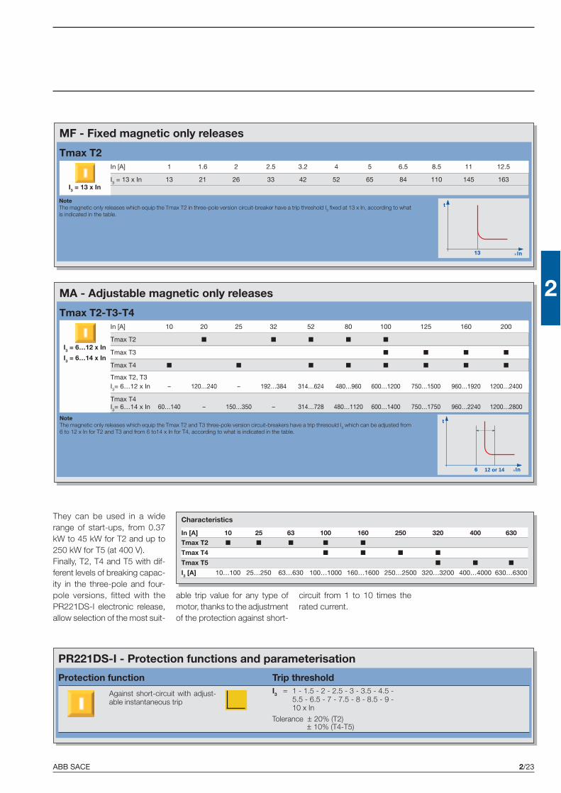
ABB SACE 2/23
2
MF - Fixed magnetic only releases
I3 = 13 x In
Tmax T2In [A] 1 1.6 2 2.5 3.2 4 5 6.5 8.5 11 12.5
I3 = 13 x In 13 21 26 33 42 52 65 84 110 145 163
MA - Adjustable magnetic only releases
Tmax T2-T3-T4In [A] 10 20 25 32 52 80 100 125 160 200
Tmax T2 ■ ■ ■ ■ ■
Tmax T3 ■ ■ ■ ■
Tmax T4 ■ ■ ■ ■ ■ ■ ■ ■
Tmax T2, T3I3= 6…12 x In – 120…240 – 192…384 314…624 480…960 600…1200 750…1500 960…1920 1200…2400
Tmax T4I3= 6…14 x In 60…140 – 150…350 – 314…728 480…1120 600…1400 750…1750 960…2240 1200…2800
NoteThe magnetic only releases which equip the Tmax T2 and T3 three-pole version circuit-breakers have a trip thresould I3 which can be adjusted from6 to 12 x In for T2 and T3 and from 6 to14 x In for T4, according to what is indicated in the table.
NoteThe magnetic only releases which equip the Tmax T2 in three-pole version circuit-breaker have a trip threshold I3 fixed at 13 x In, according to whatis indicated in the table.
PR221DS-I - Protection functions and parameterisation
Protection function Trip threshold
Against short-circuit with adjust-able instantaneous trip
I3 = 1 - 1.5 - 2 - 2.5 - 3 - 3.5 - 4.5 -5.5 - 6.5 - 7 - 7.5 - 8 - 8.5 - 9 -10 x In
Tolerance ± 20% (T2)± 10% (T4-T5)
They can be used in a widerange of start-ups, from 0.37kW to 45 kW for T2 and up to250 kW for T5 (at 400 V).Finally, T2, T4 and T5 with dif-ferent levels of breaking capac-ity in the three-pole and four-pole versions, fitted with thePR221DS-I electronic release,allow selection of the most suit-
I3 = 6…12 x In
I3 = 6…14 x In
able trip value for any type ofmotor, thanks to the adjustmentof the protection against short-
circuit from 1 to 10 times therated current.
Characteristics
In [A] 10 25 63 100 160 250 320 400 630Tmax T2 ■ ■ ■ ■ ■
Tmax T4 ■ ■ ■ ■
Tmax T5 ■ ■ ■
I3 [A] 10…100 25…250 63…630 100…1000 160…1600 250…2500 320…3200 400…4000 630…6300
12 or 14

ABB SACE2/24
2
1SD
C21
0328
F000
4
PR222MP - Electronic overcurrent releases
Tmax T4-T5In [A] 100 160 200 320 400
T4 250 N, S, L ■ ■ ■
T5 400 N, S, L ■ ■
40…100 64…160 80…200 128…320 160…400
3…10 x I1
600…1300 960…2080 1200…2600 1920…4160 2400…5200
0.4 x I1
I1 [A]
I5 [A]
I3 [A]
I6 [A]
Integrated protectionPR222MP electronic overcurrent releases
In the three-pole version, the Tmax T4 and T5 circuit-breakers arefitted with PR222MP electronic releases. This makes it possible toobtain functions which guarantee high trip precision, extreme reli-ability and immunity to variations in the external temperature.The PR222MP releases fully integrated on board the circuit-breakerguarantee complete protection of the motor. In fact, it is notnecessary to provide the help of an external thermal relay forprotection against overloads as, on the other hand, occurs withthe standard solution.The PR222MP can be connected to a contactor for the basic pro-
Circuit-breakers for motor protectionIntegrated protection: PR222MP
Characteristics of the SACE PR222MP electronic releaseOperating temperature -25 °C … +70 °CRelative humidity 90%Operating frequency 45…66 Hz
Electromagnetic compatibility (LF and HF) IEC 60947-2 Annex FMedium time before failure (MTBF) 15 years (at 45°C)
tection function (NORMALmode) of the motor: the circuit-breaker can control contactoropening in the case of a fault(excluding short-circuit), bymeans of the SACE PR212/CIaccessory control unit. In fact,
a contactor has breaking capacities at high currents which areless efficient than the circuit-breaker, but a high number of possi-ble operations consistently higher than those of the circuit-breaker(about 1.000.000). The combination of the two devices thereforeoptimises motor protection and control.However, the PR222MP can also be connected directly to themotor (HEAVY mode). In this case, the circuit-breaker is calledon to protect the plant in any case, without the help of the contac-tor: this solution is suggested for motors with a low number ofoperations.
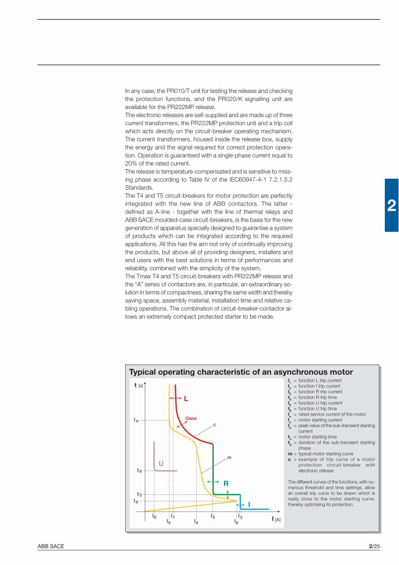
ABB SACE 2/25
2
Typical operating characteristic of an asynchronous motorl1 = function L trip currentl3 = function I trip currentI5 = function R trip currentt5 = function R trip timeI6 = function U trip currentt6 = function U trip timele = rated service current of the motorla = motor starting currentIp = peak value of the sub-transient starting
currentta = motor starting timetp = duration of the sub-transient starting
phasem = typical motor starting curvec = example of trip curve of a motor
protection circuit-breaker withelectronic release
The different curves of the functions, with nu-merous threshold and time settings, allowan overall trip curve to be drawn which isreally close to the motor starting curve,thereby optimising its protection.
In any case, the PR010/T unit for testing the release and checkingthe protection functions, and the PR020/K signalling unit areavailable for the PR222MP release.The electronic releases are self-supplied and are made up of threecurrent transformers, the PR222MP protection unit and a trip coilwhich acts directly on the circuit-breaker operating mechanism.The current transformers, housed inside the release box, supplythe energy and the signal required for correct protection opera-tion. Operation is guaranteed with a single-phase current equal to20% of the rated current.The release is temperature-compensated and is sensitive to miss-ing phase according to Table IV of the IEC60947-4-1 7.2.1.5.2Standards.The T4 and T5 circuit-breakers for motor protection are perfectlyintegrated with the new line of ABB contactors. The latter -defined as A-line - together with the line of thermal relays andABB SACE moulded-case circuit-breakers, is the basis for the newgeneration of apparatus specially designed to guarantee a systemof products which can be integrated according to the requiredapplications. All this has the aim not only of continually improvingthe products, but above all of providing designers, installers andend users with the best solutions in terms of performances andreliability, combined with the simplicity of the system.The Tmax T4 and T5 circuit-breakers with PR222MP release andthe “A” series of contactors are, in particular, an extraordinary so-lution in terms of compactness, sharing the same width and therebysaving space, assembly material, installation time and relative ca-bling operations. The combination of circuit-breaker-contactor al-lows an extremely compact protected starter to be made.

ABB SACE2/26
2
1SD
C21
0330
F000
41S
DC
2103
33F0
004
1SD
C21
0335
F000
4
Protection functionsFunction L
Function L protects the motor against overloads according to the indications and classes defined bythe IEC 60947-4-1 Standard.The protection is based on a pre-defined model (ABB SACE international patent) which, by simulat-ing the copper and iron over-temperatures inside the motor, allows precise safeguarding of themotor. The protection intervenes when the established over-temperature is reached. The trip time isfixed by selecting the trip class defined in the above-mentioned Standard.The function is temperature-compensated and sensitive to a missing/unbalanced phase accordingto the IEC 60947-4-1 Standard.In the case of an auxiliary power supply, the thermal memory function is guaranteed, which allowsthe release to continue to calculate the motor temperature even following an opening.Function L, which cannot be excluded, can be set manually to I1=0.4…1 x In with 60 thresholdswhich can be set by means of the dip-switches on the front of the release, or electronically by meansof the SACE PR010T test and configuration unit.The starting class of the motor must then be selected, which determines the trip time for overloadaccording to the IEC 60947-4-1 4.7.3 Table II Standards: class 10 A corresponds to a trip timet1= 4s, class 10 to t1= 8s, class 20 to t1= 16s and class 30 to t1= 24s at 7.2 x In. Setting this trip timecan also be carried out electronically with the PR010T: the electronic steps are equal to 1s.Tripping of this protection leads to contactor opening (with the PR212/CI unit). Any anomaly of thecontactor would make the circuit-breaker open, thanks to the BACK UP function.For protection L, there is then a pre-alarm and an alarm LED: the pre-alarm threshold value (cannotbe either excluded or modified by the user) is equal to 0.9 x I1 and the LED is permanently lit, whereasit flashes in case of alarm (I > 1.05s x I1).
Function R: protection against rotor block
Function R protects the motor against possible rotor block during operation. Protection R has thecharacteristic of protecting the motor in two different ways, according to whether the fault is presentat start-up or whether it is present during normal service of an already active plant.In the former case, protection R is linked to protection L for time selection as well: in the presence ofa fault during start-up, protection R is inhibited for a time equal to the time set with the trip class.Once this time is exceeded, protection R becomes active leading to a trip after a fixed set t5 time.In the latter case, protection R is already active and the protection tripping time will be equal to t5.The protection intervenes when at least one of the phase currents exceeds the established value andremains over that threshold for time t5.Function R can be set manually I5= 3…10 x I1 with 8 thresholds which can be set by means of thedip-switches on the front of the release, or with 70 thresholds by means of the SACE PR010T testand configuration unit (steps of 0.1 x I1). The trip time t5 can be set to 1, 4, 7 or 10 seconds by meansof a dip-switch, or with steps of 0.5s by means of PR010T.Tripping of this protection leads to contactor opening (with the PR212/CI unit); any anomaly of thecontactor would make the circuit-breaker open, thanks to the BACK UP function.
Function I: protection against short-circuit
This protection function intervenes in the case of a short-circuit between phases. It is sufficient forjust a single phase to exceed the set threshold to cause immediate opening of the circuit-breaker(protection cannot be excluded). The trip current can be adjusted up to 13 times the rated current ofthe release with 8 thresholds which can be set by means of a dip-switch or with 70 thresholds bymeans of the PR010T (steps of 0.1 x In).To prevent unwarranted trips during starting, the protection recognises whether the motor to beprotected is in the starting phase or whether there is a short-circuit: this is to allow starting in com-pletely safe conditions.Tripping of this protection makes the circuit-breaker open.
Circuit-breakers for motor protectionIntegrated protection: PR222MP

ABB SACE 2/27
2
Function U: protection against missing phase and/or unbalanced
Function U can be used in those cases where a particularly precise control is needed regardingphase missing/unbalanced. This protection can be excluded and intervenes if the effective value ofone or two currents drops below the level equal to 0.4 of the current I1 set for protection L andremains there for longer than 4 seconds.This protection can be set electronically with the PR010T from 0.4 to 0.9 x I1 with time adjustablebetween 1 and 10s (steps of 0.5s).Tripping of this protection leads to contactor opening (with the PR212/CI unit); any anomaly of thecontactor would make the circuit-breaker open, thanks to the BACK UP function.
Parameterisation of the PR222MP release
Man/Elt: by means of a dip switch located on the front, the release can be provided for manualparameterisation (Man) of the thresholds and times acting directly on the dip switches located on thefront of the release or with electronic parameterisation (Elt) by means of the PR010T.
Reset Mode
AUTO/Man: this function (AUTO) allows the state of activation of the PR212/CI to be automaticallyreset following contactor trip for L function, after a fixed time of 15s. The AUTO reset is only possiblewhen there is an auxiliary voltage.
Setting the working modes
Normal: the Normal mode foresees the use of a circuit-breaker and a contactor: this configurationmakes intervention towards the contactor possible, through the PR212/CI unit, when the PR222MPconsiders this appropriate.Heavy: on the other hand, the heavy mode foresees the use of only the circuit-breaker and thereforethe PR222MP sends the trip signal directly to the circuit-breaker.
BACK UP Function
This protection is conceived to manage the possibility that an opening command sent to the contac-tor might not have a positive outcome, i.e. that the contactor does not intervene. In this case, afterhaving waiting for the time defined using the dip switch “k time” (min = 80ms or max = 160ms), thePR222MP sends a trip signal to the circuit-breaker.Introducing a time delay between the command sent to the contactor and the back-up one is nec-essary to compensate the contactors actuation time.
Setting the PTC protection
PTC: this protection, by means of a PTC sensor inserted in the motor, controls the internal tempera-ture. In case of overtemperature, the PR222MP will control opening of the contactor (when in “Nor-mal” mode) or circuit-breaker (when in “Heavy” mode).0/1: is a generic contact defined by the user and has nothing to do with the meaning of the PTC.
1SD
C21
0332
F000
41S
DC
2103
31F0
004

ABB SACE2/28
2
1SD
C21
0195
F000
4
Circuit-breakers for motor protectionIntegrated protection: PR222MP
PR222MP
Protection LAgainst motor overload
Protection UAgainst phase
current unbalance orloss of phase
Setting the work methods
Setting the resetfollowing trip- manual- automatic
Socket for connectionof SACE PR010/T test unit
Socket for SACE TT1test unit
Protection RAgainst rotor block Protection I
Against short-circuitwith instantaneous trip
Man/EltRelease parametrisation
methods
Setting the back-up time
Selection between:- PTC(1) temperature sensor input- 0/1 generic input
(1) A special input is available to connect a PTC temperature probe, inserted in the motor to be protected
ClassClass of motor startingaccording to the IEC60947-4-1 Standards

ABB SACE 2/29
2
PR222MP - Protection functions and parameterisationProtection functions Trip threshold Trip curves(1)
Against overload with longinverse time delay trip andtrip characteristic accordingto an inverse time curve
NOTEXCLUDABLE
EXCLUDABLE
Against rotor block with de-layed trip and trip character-istic with definite time
Manual settingI1 = 0.4…1 x In with step
0.01 x In
Electronic settingI1 = 0.4…1 x In with step
0.01 x In
Tolerance: ± 15%
Manual settingTrip classes: 10 A - 10 - 20 - 30(IEC 60497-4-1)t1 = 4-8-16-24s where t1 is the trip time at
7.2 x I1 cold, depending on the classselected
Electronic settingt1 = 4…24s (step 1s)
Tolerance: ± 15%
Manual settingI5 = OFF - 3 - 4 - 5 - 6 - 7 - 8 -
9 - 10 x I1
Electronic settingI5 = OFF - 3…10 x I1
(step 0.1 x I1)
Tolerance: ± 15%
Manual settingt5 = 1 - 4 - 7 - 10 s
Electronic settingt5 = 1…10s (step 0.5s)
Tolerance: ± 10%
Manual settingI3 = 6 - 7 - 8 - 9 - 10 - 11 - 12 -
13 x In
Electronic settingI3 = 6 -…-13 x In (step 0.1 x In)
Tolerance: ± 15%
NOTEXCLUDABLE
Against short-circuit withadjustable instantaneous trip
Manual settingI6 = ON (0.4 x I1) - OFF
Electronic settingI6 = 0.4…0.9 x I1 - OFF
Tolerance: ± 15%
EXCLUDABLE
Against phase current unbal-ance or loss of phase with in-verse long time delay trip andtrip characteristic with definitetime
Manual settingt6 = 4s
Electronic settingt6 = 1…10s (step 0.5s)
Tolerance: ± 10%
(1) These tolerances hold in the following conditions:– self-powered relay at full power and/or auxiliary supply;– two or three-phase power supply.

ABB SACE
2
2/31
Circuit-breakers forapplications up to 1000 V
Index
Tmax circuit-breakers for applications up to 1000 V
Electrical characteristics ...................................................................................................... 2/32

ABB SACE2/32
2
The range of circuit-breakers for applications in direct current and in alternating current up to 1000 Valso comes into the panorama of the Tmax proposal.The typical sectors of use are installations in mines, road or rail tunnels, traction and industrial appli-cations in general.The circuit-breakers are available in the three-pole and four-pole version with TMD or TMA adjust-able thermomagnetic releases for use in direct and alternating current, or in the three-pole versionwith PR221DS and PR222DS/P electronic releases for applications in alternating current.The dimensions of these circuit-breakers are the same as the standard ones. Furthermore, they canalso be combined with all the accessories available for the Tmax series, except for the residualcurrent release, and can be converted into plug-in or withdrawable version using the conversion kitsand fixed parts of standard circuit-breakers.
Tmax T4 Tmax T5Rated uninterrupted current, Iu [A] 250 400, 630
Poles [No.] 3 3Rated service voltage, Ue (AC) 50-60 Hz [V] 1000 1000
Rated impulse withstand voltage, Uimp [kV] 8 8Rated insulation voltage, Ui [V] 1000 1000
Test voltage at industrial frequency for 1 min. [V] 3500 3500Rated ultimate short-circuit breaking capacity, Icu L V L V
(AC) 50-60 Hz 1000 V [kA] 12 20 12 20Rated service short-circuit breaking capacity, Ics [%Icu]
(AC) 50-60 Hz 1000 V [kA] 100% 100% 75% 75%Rated short-circuit making capacity, Icm [kA]
(AC) 50-60 Hz 1000 V [kA] 24 40 24 40Category of utilisation (EN 60947-2) A B (400 A)(*) - A (630A)
Isolation behaviour ■ ■
Reference Standard IEC 60947-2 IEC 60947-2
Electronic releases PR221DS-LS ■ ■
PR221DS-I ■ ■
PR222DS-LSI ■ ■
PR222DS-LSIG ■ ■
Interchangeability ■ ■
Versions F-P-W F-P-W
Terminals fixed F-FCCu-FCCuAl-EF-ES-R-MC F-FCCu-FCCuAl-EF-ES-Rplug-in FCCu-FCCuAl-EF-ES-HR-VR FCCu-FCCuAl-EF-ES-HR-VR
withdrawable FCCu-FCCuAl-EF-ES-HR-VR FCCu-FCCuAl-EF-ES-HR-VRMechanical life 20000 20000
240 120Basic dimensions - fixed version 3 poles L [mm] 105 140
D [mm] 103.5 103.5H [mm] 205 205
Weight fixed 3 poles 2.35 3.25plug-in 3 poles 3.6 5.15
withdrawable 3 poles 3.85 5.4
Circuit-breakers for applications up to 1000 VElectrical characteristics
Circuit-breakers with electronic release for applications at 1000 V in AC
Electronic releases for applications up to 1000 V AC -PR221DS, PR222DS/PD and PR222DS/P
In [A] 100 250 400 630
T4 250 ■ ■
T5 400 ■
T5 630 ■
TERMINAL CAPTIONF = FrontEF = Front extendedES = Front extended spreadFC Cu = Front for copper cablesFC CuAl = Front for CuAl cablesR = Rear orientatedHR = Rear in horizontal flat barVR = Rear in vertical flat barMC = Multicable(*) Icw = 5 kA

ABB SACE 2/33
2
Thermomagnetic releases for applications at 1000 V in AC/DC - TMD and TMA
In [A] 32 50 80 100 125 160 200 250 400 630
Neutral [A] - 100% 32 50 80 100 125 160 200 250 400 630
T4 250 ■ ■ ■ ■ ■ ■ ■ ■
T5 400 ■
T5 630 ■
I3 = 10 x In [A] 320 500
I3 = 5...10 x In [A] - - 400…800 500…1000 625…1250 800…1600 1000…2000 1250…2500 2000…4000 3150…6300
Tmax T4 Tmax T5Rated uninterrupted current, Iu [A] 250 400, 630
No. Poles Nr. 4 4Rated service voltage, Ue (AC) 50-60 Hz [V] 1000 1000
Rated impulse withstand voltage, Uimp [kV] 8 8Rated insulation voltage, Ui [V] 1000 1000
Test voltage at industrial frequency for 1 min. [V] 3500 3500Rated ultimate short-circuit breaking capacity, Icu V V
(AC) 50-60 Hz 1000 V [kA] 20 20(DC) 1000 V, 4 poles in series [kA] 40 40
Rated service short-circuit breaking capacity, Ics [%Icu](AC) 50-60 Hz 1000 V [kA] 100% 75%
Rated short-circuit making capacity, Icm [kA](AC) 50-60 Hz 1000 V [kA] 40 40
Category of utilisation (EN 60947-2) A B (400 A)(*) - A (630A)Isolation behaviour ■ ■
Reference Standard IEC 60947-2 IEC 60947-2Thermomagnetic releases TMD ■ –
TMA ■ ■
Interchangeability ■ –
Versions F-P-W F-P-WTerminali fixed F-FCCu-FCCuAl-EF-ES-MC F-FCCu-FCCuAl-EF-ES
plug-in FCCu-FCCuAl-EF-ES-HR-VR FCCu-FCCuAl-EF-ES-HR-VRwithdrawable FCCu-FCCuAl-EF-ES-HR-VR FCCu-FCCuAl-EF-ES-HR-VR
Mechanical life 20000 20000240 120
Basic dimensions - fixed version 3 poles L [mm] 105 1404 poles L [mm] 140 184
D [mm] 103.5 103.5H [mm] 205 205
Weight fixed 3 poles 2.35 3.25plug-in 3 poles 3.6 5.15
withdrawable 3 poles 3.85 5.4
Circuit-breakers with thermomagnetic release for applications at 1000 V in AC/DC
TERMINAL CAPTIONF = FrontEF = Front extended
ES = Front extended spreadFC Cu = Front for copper cables
FC CuAl = Front for CuAl cablesR = Rear orientated
I1= 0.7…1 x In
I3 = 10 x InI3 = 5…10 x In
HR = Rear in horizontal flat barVR = Rear in vertical flat bar
MC = Multicable(*) Icw = 5 kA


ABB SACE
2
2/35
Switch-disconnectors
Index
Switch-disconnectors
Electrical characteristics ...................................................................................................... 2/36

ABB SACE2/36
2
Switch-disconnectorsElectrical characteristics
The Tmax switch-disconnectors derive from the corresponding circuit-breakers, of which they keepthe overall dimensions, versions, fixing systems and the possibility of mounting accessories un-changed. This version only differs from the circuit-breakers in the absence of the protection re-leases.They are characterised by a rated voltage of 690 V in alternating current and 750 V in direct current.
Applications
They can be used as general circuit-breakers in sub-switchboards as switching and isolation partsfor lines, busbars or groups of apparatus, or as bus-ties. They can be part of general isolationdevices of groups of machines or of complexes for motor switching and protection.
Isolation
The main function carried out by this apparatus consists of isolation of the circuit they are inserted in.Once the contacts are open they are at a distance which prevents an arc from striking, in accord-ance with the prescriptions in the standards regarding isolation behaviour. The position of the oper-ating lever corresponds definitely with that of the contacts (positive operation).
Tmax T1DConventional thermal current, Ith [A] 160
Rated service current in category AC23, Ie [A] 125Poles [No.] 3/4
Rated service voltage, Ue (AC) 50-60 Hz [V] 690(DC) [V] 500
Rated impulse withstand voltage, Uimp [kV] 8Rated insulation voltage, Ui [V] 800
Test voltage at industrial frequency for 1 minute [V] 3000Rated short-circuit making capacity, Icm (min) switch-disconnector only [kA] 2.8
(max) with circuit-breakeron supply side [kA] 187
Rated short-time withstand current for 1s, Icw [kA] 2
Insulation behaviour ■
Reference Standard IEC 60947-3
Versions FTerminals FCCu-EF-FCCuAl-HR
Mechanical life [No. Operations] 25000[No. Hourly Operations] 120
Basic dimensions, fixed 3 poles L [mm] 764 poles L [mm] 102
H [mm] 130D [mm] 70
Weight fixed 3/4 poles [kg] 0.9/1.2plug-in 3/4 poles [kg] –
withdrawable 3/4 poles [kg] –
Coordination between switch-disconnectors and circuit-breakers [380/415 V AC]T1 T2 T3
B C N N S H L N SIcu [kA] 16 25 36 36 50 70 85 36 50T1D 160 16 25 36 36 50 70 85T3D 250 36 50
T4D 320T5D 400T5D 630

ABB SACE 2/37
2
Protection
Each switch-disconnector must be protected on the supply side by a coordinated device whichsafeguards it against short-circuits. The coordination table below indicates the Tmax circuit-breakerwhich can carry out the protection function for each switch-disconnector. These are always piecesof apparatus of a size corresponding to or smaller than that of the switch disconnector.
Tmax T3D Tmax T4D Tmax T5D250 320 400/630
200 320 400/6303/4 3/4 3/4
690 690 690500 750 750
8 8 8800 800 800
3000 3000 30005.3 5.3 11
105 440 4403.6 3.6 6
■ ■ ■
IEC 60947-3 IEC 60947-3 IEC 60947-3
F-P F-P-W F-P-WF-FCCuAl-FCCu-EF-ES-R F-FCCuAl-FCCu-EF-ES-R-MC-HR-VR F-FCCuAl-FCCu-EF-ES-R-HR-VR
25000 20000 20000120 120 120
105 105 140140 140 184
150 205 20570 103.5 103.5
2.1/3 2.35/3.05 3.25/4.152.1/3.7 3.6/4.65 5.15/6.65
– 3.85/4.9 5.4/6.9
Making capacity
The making capacity Icm is a performance of notable importance since a switch-disconnector mustbe able to withstand the dynamic, thermal and current stresses which can occur during closurewithout being destroyed, up to the short-circuit closing conditions.
Withstand capacity in closed position
This identifies the capacity to maintain the closed position for short-time overcurrents. It is a signifi-cant parameter which qualifies the performances of this apparatus.
T4 T5 400 T5 630N S H L V N S H L V N S H L V36 50 70 120 200 36 50 70 120 200 36 50 70 120 200
36 50
36 50 70 120 20036 50 70 120 200
36 50 70 120 200
