the readout thickness versus the measured thickness for a - oda
TRANSCRIPT
PROOF COPY [11-560R1] 039112MPH
The readout thickness versus the measured thickness for a range of SFM1 and FFDM units
2 Ingrid H. R. Haugea)
3 Oslo and Akershus University College of Applied Sciences, Faculty of Health Sciences,4 Department of Radiography and Dental Technology, P. O. Box 4, St. Olavs plass, NO-0130 Oslo,5 Norway and Norwegian Radiation Protection Authority, P. O. Box 55, NO-1332 Østeras, Norway
6 Peter Hogg and Katy Szczepura7 Directorate of Radiography, University of Salford, Salford M6 6PU, United Kingdom
8 Paul Connolly9 Integrated Radiological Services Ltd., Unit 188 Century Building, Tower Street, Brunswick Business Park,
10 Liverpool L3 4BJ, United Kingdom
11 George McGill12 The Christie NHS Foundation Trust, Wilmslow Road, Manchester M20 4BX, United Kingdom
13 Claire Mercer14 Royal Bolton Hospital NHS Foundation Trust, Minerva Road, Farnworth, Bolton BL4 0JR, United Kingdom
15 (Received 13 May 2011; revised 28 October 2011; accepted for publication 2 November 2011;16 published 0 0000)
17 Purpose: To establish a simple method to determine breast readout accuracy on mammography18 units.19 Methods: A thickness measuring device (TMD) was used in conjunction with a breast phantom.20 This phantom had compression characteristics similar to human female breast tissue. The phantom21 was compressed, and the thickness was measured using TMD and mammography unit readout.22 Measurements were performed on a range of screen film mammography (SFM) and full-field digital23 mammography (FFDM) units (8 units in total; 6 different models/manufacturers) for two different24 sized paddles and two different compression forces (60 and 100 N).25 Results: The difference between machine readout and TMD for the breast area, when applying 10026 N compression force, for nonflexible paddles was largest for GE Senographe DMRþ (24 cm� 3027 cm paddle: þ14.3%). For flexible paddles the largest difference occurred for Hologic Lorad Selenia28 (18 cm� 24 cm paddle: þ26.0%).29 Conclusions: None of the units assessed were found to have perfect correlation between measured30 and readout thickness. TMD measures and thickness readouts were different for the duplicate units31 from two different models/manufacturers. VC 2012 American Association of Physicists in Medicine.
[DOI: 10.1118/1.3663579]
Key words: mammography, breast thickness, breast compression
32 I. INTRODUCTION
33 Accurate breast thickness estimation is required in order to34 calculate the mean glandular dose (MGD).1–3 Accuracy is35 also required for density measurements (which can be used36 for predicting breast cancer risk)4 and for estimation of37 breast tissue volume.5,6 Compression paddles may deform/38 tilt during mammography and this can lead to differences39 between the actual and readout (displayed by the mammog-40 raphy machine) thickness of the compressed breast. Under41 realistic clinical imaging conditions (phantom-simulated)42 this study aimed to conduct a comparative analysis of read-43 out versus measured thicknesses over a range of mammog-44 raphy units.45 Previous studies have highlighted inaccuracies with thick-46 ness readouts of mammography machines; some of these47 studies have also proposed methods which may provide a48 better estimate of the compressed breast thickness.3,7–9
49 Diffey et al.10 found a maximum variation of 21.1 mm in the
50chest wall to nipple direction, while the paddle deformation51in the lateral direction was found to be insignificant in com-52parison to the chest wall to nipple direction. Tyson et al.9
53described a technique for measuring breast thickness by54using optical stereoscopic photogrammetry. This method55had a precision of >1 mm, and a measurement accuracy of56>0.2 mm. The readout thickness for a number of different57mammography systems was found to vary by as much as 1558mm when compressing the same breast or phantom.9 The59value of the method developed by Tyson et al.9 was its accu-60racy; system use however is labor intensive, being highly61dependent on room lighting and also on image quality.62Mawdsley et al.7 developed functions that can estimate the63compressed breast thickness based upon the machine readout64thickness and compression force reported by the machine.65This study aimed to develop a simple, clinically adaptable66and accurate method to measure the difference between the67readout and measured thickness. Building on previous68research there was particular interest in, the creation and
J_ID: MPH DOI: 10.1118/1.3663579 Date: 10-December-11 Stage: Page: 1 Total Pages: 9
ID: varadharajans Time: 11:53 I Path: Q:/3b2/MPH#/Vol00000/110439/APPFile/AI-MPH#110439
1 Med. Phys. 39 (1), January 2012 0094-2405/2012/39(1)/1/9/$30.00 VC 2012 Am. Assoc. Phys. Med. 1
PROOF COPY [11-560R1] 039112MPH
69 documentation of the physical breast phantom characteris-70 tics, particularly in relation to in-vivo female human breast71 tissue. In order to investigate how the thickness readout and72 the thickness across the breast correlated, a breast thickness73 measuring device (TMD) was constructed.
74 II. METHODS AND MATERIALS
75 The method comprised of three stages. First, a clinically76 realistic breast phantom and backing plate with the creation77 of a rigid torso was tested. Second, the TMD was designed78 and tested. Finally, using the TMD, the breast phantom with79 its backing plate was used to assess several mammography80 units/paddle combinations.
81 II.A. Design, creation, and validation of breast82 phantom
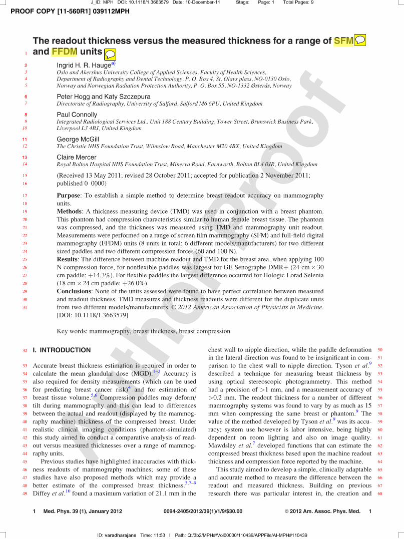
83 Three breast prostheses (small (220 cm3), medium (360 cm3),84 and large (700 cm3), Trulife, Sheffield, United Kingdom) were85 assessed for their compression characteristics. Each of the breast86 prostheses were adhered onto a semiflexible backing plate. The87 backing plate was mounted onto a rigid torso (Fig. 1) in order to88 simulate how a real breast will behave when it is compressed.89 The resistance to compression incurred by the torso changed the90 compressibility of the phantom to better simulate a real breast.91 Six rubber balloons were glued onto the flexible backing92 plate. The balloons gave minor mobility similar to pectoral93 muscle and fascia. The phantom was glued onto the balloons94 and covered with layers of latex. The latex was painted95 across the surface of the phantom and along the edges, with96 fewer layers across the surface than around the edges. The97 backing plate was mounted onto a rigid torso (CIRS, Nor-98 folk) using two ratchet straps, one above and one below the99 breast phantom. Before compressing the breast phantom, a
100 lubricant was applied to the phantom. This allowed the com-101 pression paddle to slide smoothly over the breast surface102 when pressure was applied.103 Using the three breast phantoms, mounted as described,104 compression (N)/thickness (mm) graphs were generated105 from 40 to 100 N stepping through 10 N values. For each106 phantom, the compressed breast thickness data were aver-107 aged and normalized (the data were normalized to 1 for 40 N
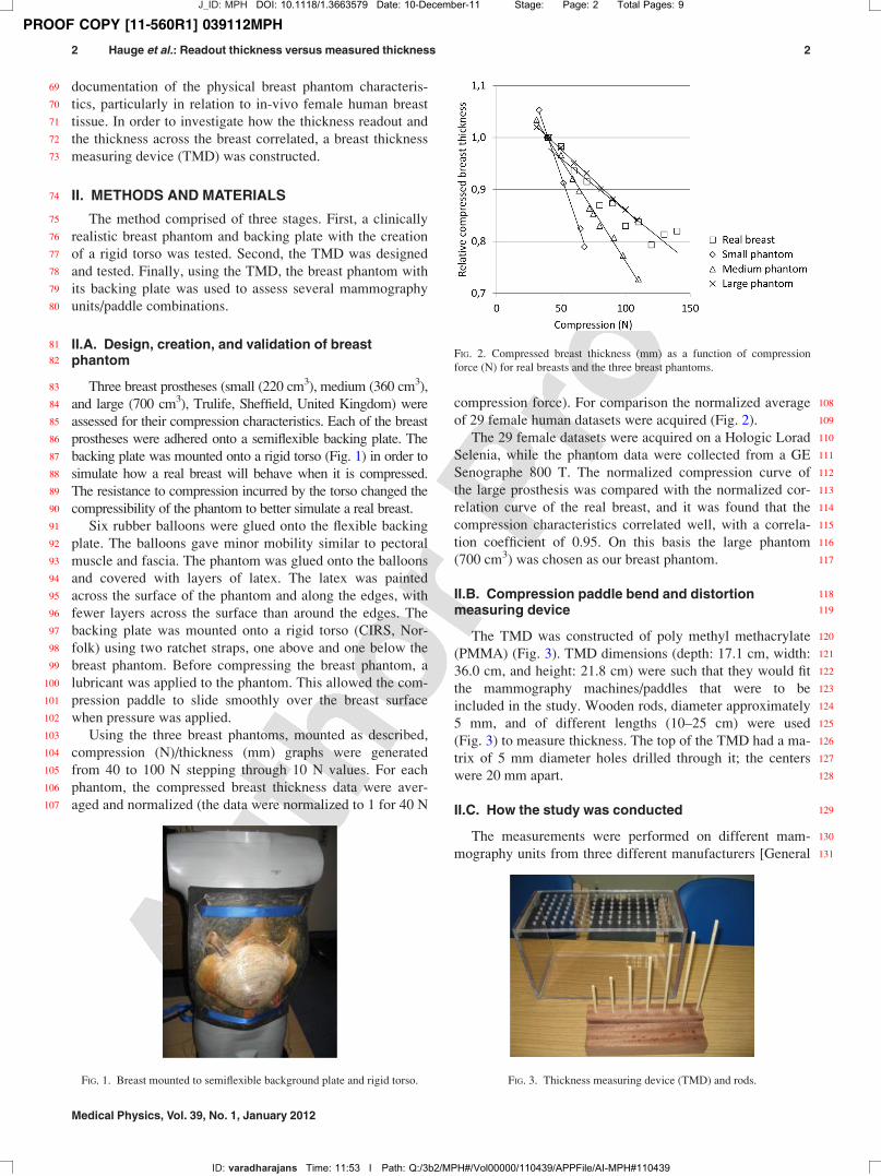
108compression force). For comparison the normalized average109of 29 female human datasets were acquired (Fig. 2).110The 29 female datasets were acquired on a Hologic Lorad111Selenia, while the phantom data were collected from a GE112Senographe 800 T. The normalized compression curve of113the large prosthesis was compared with the normalized cor-114relation curve of the real breast, and it was found that the115compression characteristics correlated well, with a correla-116tion coefficient of 0.95. On this basis the large phantom117(700 cm3) was chosen as our breast phantom.
118II.B. Compression paddle bend and distortion119measuring device
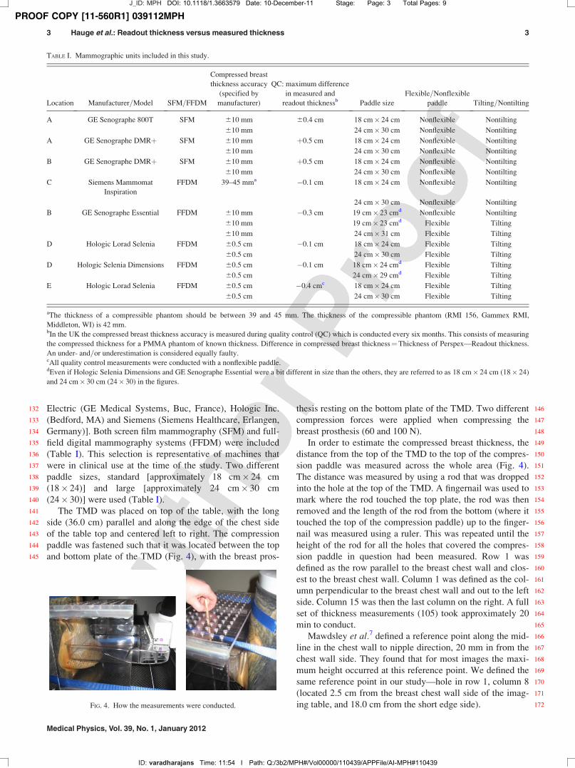
120The TMD was constructed of poly methyl methacrylate121(PMMA) (Fig. 3). TMD dimensions (depth: 17.1 cm, width:12236.0 cm, and height: 21.8 cm) were such that they would fit123the mammography machines/paddles that were to be124included in the study. Wooden rods, diameter approximately1255 mm, and of different lengths (10–25 cm) were used126(Fig. 3) to measure thickness. The top of the TMD had a ma-127trix of 5 mm diameter holes drilled through it; the centers128were 20 mm apart.
129II.C. How the study was conducted
130The measurements were performed on different mam-131mography units from three different manufacturers [General
FIG. 1. Breast mounted to semiflexible background plate and rigid torso.
FIG. 2. Compressed breast thickness (mm) as a function of compression
force (N) for real breasts and the three breast phantoms.
FIG. 3. Thickness measuring device (TMD) and rods.
J_ID: MPH DOI: 10.1118/1.3663579 Date: 10-December-11 Stage: Page: 2 Total Pages: 9
ID: varadharajans Time: 11:53 I Path: Q:/3b2/MPH#/Vol00000/110439/APPFile/AI-MPH#110439
2 Hauge et al.: Readout thickness versus measured thickness 2
Medical Physics, Vol. 39, No. 1, January 2012
PROOF COPY [11-560R1] 039112MPH
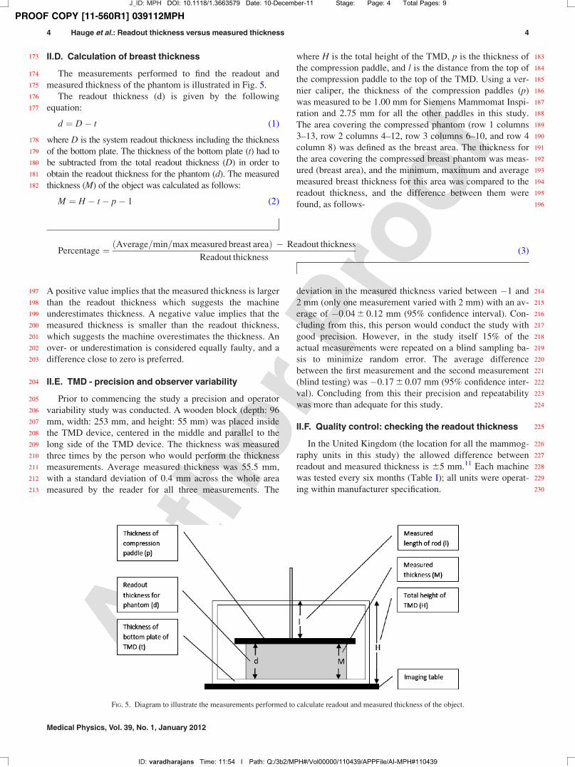
132 Electric (GE Medical Systems, Buc, France), Hologic Inc.133 (Bedford, MA) and Siemens (Siemens Healthcare, Erlangen,134 Germany)]. Both screen film mammography (SFM) and full-135 field digital mammography systems (FFDM) were included136 (Table I). This selection is representative of machines that137 were in clinical use at the time of the study. Two different138 paddle sizes, standard [approximately 18 cm� 24 cm139 (18� 24)] and large [approximately 24 cm� 30 cm140 (24� 30)] were used (Table I).141 The TMD was placed on top of the table, with the long142 side (36.0 cm) parallel and along the edge of the chest side143 of the table top and centered left to right. The compression144 paddle was fastened such that it was located between the top145 and bottom plate of the TMD (Fig. 4), with the breast pros-
146thesis resting on the bottom plate of the TMD. Two different147compression forces were applied when compressing the148breast prosthesis (60 and 100 N).149In order to estimate the compressed breast thickness, the150distance from the top of the TMD to the top of the compres-151sion paddle was measured across the whole area (Fig. 4).152The distance was measured by using a rod that was dropped153into the hole at the top of the TMD. A fingernail was used to154mark where the rod touched the top plate, the rod was then155removed and the length of the rod from the bottom (where it156touched the top of the compression paddle) up to the finger-157nail was measured using a ruler. This was repeated until the158height of the rod for all the holes that covered the compres-159sion paddle in question had been measured. Row 1 was160defined as the row parallel to the breast chest wall and clos-161est to the breast chest wall. Column 1 was defined as the col-162umn perpendicular to the breast chest wall and out to the left163side. Column 15 was then the last column on the right. A full164set of thickness measurements (105) took approximately 20165min to conduct.166Mawdsley et al.7 defined a reference point along the mid-167line in the chest wall to nipple direction, 20 mm in from the168chest wall side. They found that for most images the maxi-169mum height occurred at this reference point. We defined the170same reference point in our study—hole in row 1, column 8171(located 2.5 cm from the breast chest wall side of the imag-172ing table, and 18.0 cm from the short edge side).
TABLE I. Mammographic units included in this study.
Location Manufacturer=Model SFM=FFDM
Compressed breast
thickness accuracy
(specified by
manufacturer)
QC: maximum difference
in measured and
readout thicknessb Paddle size
Flexible=Nonflexible
paddle Tilting=Nontilting
A GE Senographe 800T SFM 610 mm 60.4 cm 18 cm� 24 cm Nonflexible Nontilting
610 mm 24 cm� 30 cm Nonflexible Nontilting
A GE Senographe DMRþ SFM 610 mm þ0.5 cm 18 cm� 24 cm Nonflexible Nontilting
610 mm 24 cm� 30 cm Nonflexible Nontilting
B GE Senographe DMRþ SFM 610 mm þ0.5 cm 18 cm� 24 cm Nonflexible Nontilting
610 mm 24 cm� 30 cm Nonflexible Nontilting
C Siemens Mammomat
Inspiration
FFDM 39–45 mma �0.1 cm 18 cm� 24 cm Nonflexible Nontilting
24 cm� 30 cm Nonflexible Nontilting
B GE Senographe Essential FFDM 610 mm �0.3 cm 19 cm� 23 cmd Nonflexible Nontilting
610 mm 19 cm� 23 cmd Flexible Tilting
610 mm 24 cm� 31 cm Flexible Tilting
D Hologic Lorad Selenia FFDM 60.5 cm �0.1 cm 18 cm� 24 cm Flexible Tilting
60.5 cm 24 cm� 30 cm Flexible Tilting
D Hologic Selenia Dimensions FFDM 60.5 cm �0.1 cm 18 cm� 24 cmd Flexible Tilting
60.5 cm 24 cm� 29 cmd Flexible Tilting
E Hologic Lorad Selenia FFDM 60.5 cm �0.4 cmc 18 cm� 24 cm Flexible Tilting
60.5 cm 24 cm� 30 cm Flexible Tilting
aThe thickness of a compressible phantom should be between 39 and 45 mm. The thickness of the compressible phantom (RMI 156, Gammex RMI,
Middleton, WI) is 42 mm.bIn the UK the compressed breast thickness accuracy is measured during quality control (QC) which is conducted every six months. This consists of measuring
the compressed thickness for a PMMA phantom of known thickness. Difference in compressed breast thickness¼Thickness of Perspex—Readout thickness.
An under- and=or underestimation is considered equally faulty.cAll quality control measurements were conducted with a nonflexible paddle.dEven if Hologic Selenia Dimensions and GE Senographe Essential were a bit different in size than the others, they are referred to as 18 cm� 24 cm (18� 24)
and 24 cm� 30 cm (24� 30) in the figures.
FIG. 4. How the measurements were conducted.
J_ID: MPH DOI: 10.1118/1.3663579 Date: 10-December-11 Stage: Page: 3 Total Pages: 9
ID: varadharajans Time: 11:54 I Path: Q:/3b2/MPH#/Vol00000/110439/APPFile/AI-MPH#110439
3 Hauge et al.: Readout thickness versus measured thickness 3
Medical Physics, Vol. 39, No. 1, January 2012
PROOF COPY [11-560R1] 039112MPH
173 II.D. Calculation of breast thickness
174 The measurements performed to find the readout and175 measured thickness of the phantom is illustrated in Fig. 5.176 The readout thickness (d) is given by the following177 equation:
d ¼ D� t (1)
178 where D is the system readout thickness including the thickness179 of the bottom plate. The thickness of the bottom plate (t) had to180 be subtracted from the total readout thickness (D) in order to181 obtain the readout thickness for the phantom (d). The measured182 thickness (M) of the object was calculated as follows:
M ¼ H � t� p� 1 (2)
183where H is the total height of the TMD, p is the thickness of184the compression paddle, and l is the distance from the top of185the compression paddle to the top of the TMD. Using a ver-186nier caliper, the thickness of the compression paddles (p)187was measured to be 1.00 mm for Siemens Mammomat Inspi-188ration and 2.75 mm for all the other paddles in this study.189The area covering the compressed phantom (row 1 columns1903–13, row 2 columns 4–12, row 3 columns 6–10, and row 4191column 8) was defined as the breast area. The thickness for192the area covering the compressed breast phantom was meas-193ured (breast area), and the minimum, maximum and average194measured breast thickness for this area was compared to the195readout thickness, and the difference between them were196found, as follows-
Percentage ¼ ðAverage=min=max measured breast areaÞ � Readout thickness
Readout thickness(3)
197 A positive value implies that the measured thickness is larger198 than the readout thickness which suggests the machine199 underestimates thickness. A negative value implies that the200 measured thickness is smaller than the readout thickness,201 which suggests the machine overestimates the thickness. An202 over- or underestimation is considered equally faulty, and a203 difference close to zero is preferred.
204 II.E. TMD - precision and observer variability
205 Prior to commencing the study a precision and operator206 variability study was conducted. A wooden block (depth: 96207 mm, width: 253 mm, and height: 55 mm) was placed inside208 the TMD device, centered in the middle and parallel to the209 long side of the TMD device. The thickness was measured210 three times by the person who would perform the thickness211 measurements. Average measured thickness was 55.5 mm,212 with a standard deviation of 0.4 mm across the whole area213 measured by the reader for all three measurements. The
214deviation in the measured thickness varied between �1 and2152 mm (only one measurement varied with 2 mm) with an av-216erage of �0.04 6 0.12 mm (95% confidence interval). Con-217cluding from this, this person would conduct the study with218good precision. However, in the study itself 15% of the219actual measurements were repeated on a blind sampling ba-220sis to minimize random error. The average difference221between the first measurement and the second measurement222(blind testing) was �0.17 6 0.07 mm (95% confidence inter-223val). Concluding from this their precision and repeatability224was more than adequate for this study.
225II.F. Quality control: checking the readout thickness
226In the United Kingdom (the location for all the mammog-227raphy units in this study) the allowed difference between228readout and measured thickness is 65 mm.11 Each machine229was tested every six months (Table I); all units were operat-230ing within manufacturer specification.
FIG. 5. Diagram to illustrate the measurements performed to calculate readout and measured thickness of the object.
J_ID: MPH DOI: 10.1118/1.3663579 Date: 10-December-11 Stage: Page: 4 Total Pages: 9
ID: varadharajans Time: 11:54 I Path: Q:/3b2/MPH#/Vol00000/110439/APPFile/AI-MPH#110439
4 Hauge et al.: Readout thickness versus measured thickness 4
Medical Physics, Vol. 39, No. 1, January 2012
PROOF COPY [11-560R1] 039112MPH
231 II.G. Quality control: checking the compression force
232 Accuracy of compression force is assessed on traceably233 calibrated scales and noted to an accuracy of 5 N every 6234 months by a medical physicist and monthly by radiogra-235 phers. The readout compression force is checked for 40, 80,236 and 120 N and also at maximum compression force (200 N).237 The accuracy of the readout compared to the measured com-238 pression force was 610 N (in accordance with IPEM 89 Ref.239 11) for all the units.
240 III. RESULTS
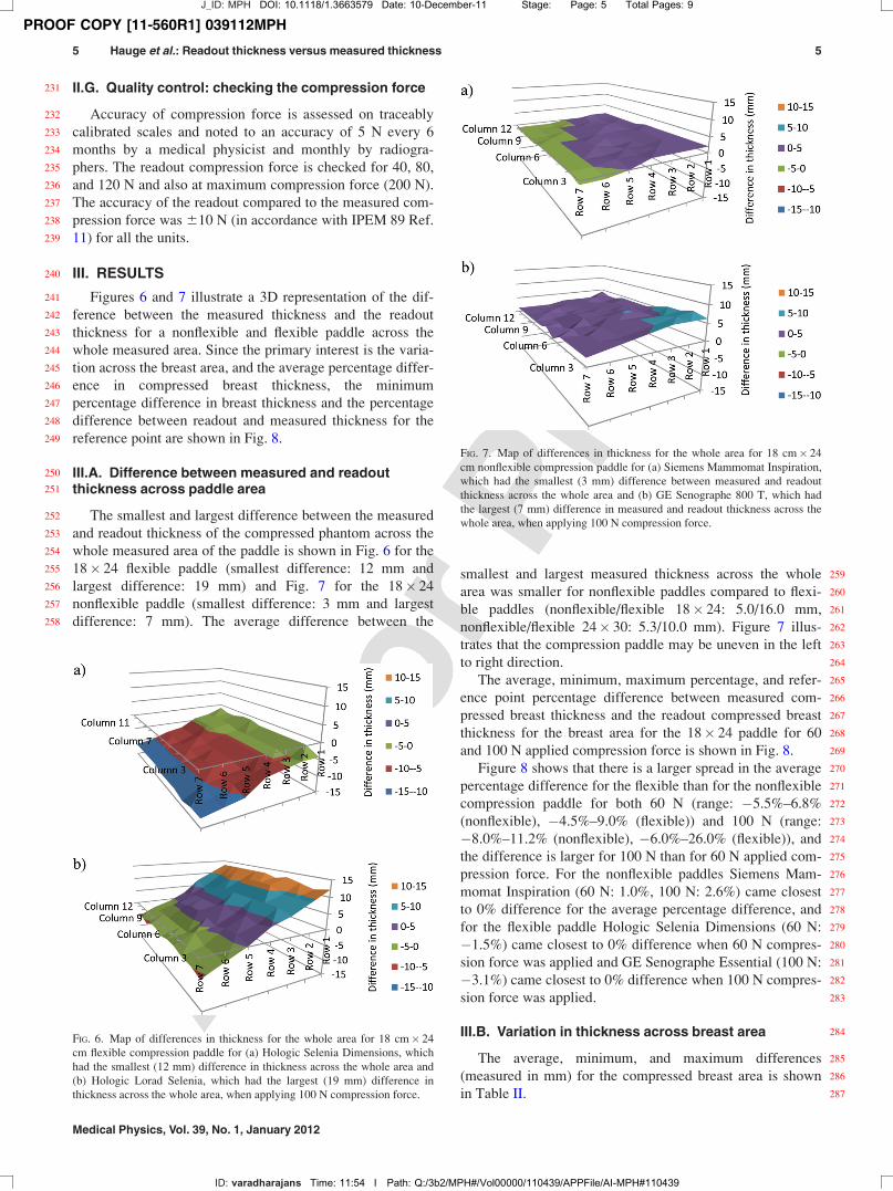
241 Figures 6 and 7 illustrate a 3D representation of the dif-242 ference between the measured thickness and the readout243 thickness for a nonflexible and flexible paddle across the244 whole measured area. Since the primary interest is the varia-245 tion across the breast area, and the average percentage differ-246 ence in compressed breast thickness, the minimum247 percentage difference in breast thickness and the percentage248 difference between readout and measured thickness for the249 reference point are shown in Fig. 8.
250 III.A. Difference between measured and readout251 thickness across paddle area
252 The smallest and largest difference between the measured253 and readout thickness of the compressed phantom across the254 whole measured area of the paddle is shown in Fig. 6 for the255 18� 24 flexible paddle (smallest difference: 12 mm and256 largest difference: 19 mm) and Fig. 7 for the 18� 24257 nonflexible paddle (smallest difference: 3 mm and largest258 difference: 7 mm). The average difference between the
259smallest and largest measured thickness across the whole260area was smaller for nonflexible paddles compared to flexi-261ble paddles (nonflexible/flexible 18� 24: 5.0/16.0 mm,262nonflexible/flexible 24� 30: 5.3/10.0 mm). Figure 7 illus-263trates that the compression paddle may be uneven in the left264to right direction.265The average, minimum, maximum percentage, and refer-266ence point percentage difference between measured com-267pressed breast thickness and the readout compressed breast268thickness for the breast area for the 18� 24 paddle for 60269and 100 N applied compression force is shown in Fig. 8.270Figure 8 shows that there is a larger spread in the average271percentage difference for the flexible than for the nonflexible272compression paddle for both 60 N (range: �5.5%–6.8%273(nonflexible), �4.5%–9.0% (flexible)) and 100 N (range:274�8.0%–11.2% (nonflexible), �6.0%–26.0% (flexible)), and275the difference is larger for 100 N than for 60 N applied com-276pression force. For the nonflexible paddles Siemens Mam-277momat Inspiration (60 N: 1.0%, 100 N: 2.6%) came closest278to 0% difference for the average percentage difference, and279for the flexible paddle Hologic Selenia Dimensions (60 N:280�1.5%) came closest to 0% difference when 60 N compres-281sion force was applied and GE Senographe Essential (100 N:282�3.1%) came closest to 0% difference when 100 N compres-283sion force was applied.
284III.B. Variation in thickness across breast area
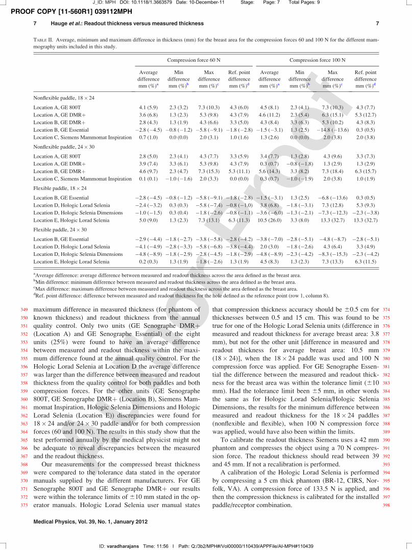
285The average, minimum, and maximum differences286(measured in mm) for the compressed breast area is shown287in Table II.
FIG. 6. Map of differences in thickness for the whole area for 18 cm� 24
cm flexible compression paddle for (a) Hologic Selenia Dimensions, which
had the smallest (12 mm) difference in thickness across the whole area and
(b) Hologic Lorad Selenia, which had the largest (19 mm) difference in
thickness across the whole area, when applying 100 N compression force.
FIG. 7. Map of differences in thickness for the whole area for 18 cm� 24
cm nonflexible compression paddle for (a) Siemens Mammomat Inspiration,
which had the smallest (3 mm) difference between measured and readout
thickness across the whole area and (b) GE Senographe 800 T, which had
the largest (7 mm) difference in measured and readout thickness across the
whole area, when applying 100 N compression force.
J_ID: MPH DOI: 10.1118/1.3663579 Date: 10-December-11 Stage: Page: 5 Total Pages: 9
ID: varadharajans Time: 11:54 I Path: Q:/3b2/MPH#/Vol00000/110439/APPFile/AI-MPH#110439
5 Hauge et al.: Readout thickness versus measured thickness 5
Medical Physics, Vol. 39, No. 1, January 2012

PROOF COPY [11-560R1] 039112MPH
288 The difference between machine readout and measured289 thickness for nonflexible paddles for the breast area, applying290 100 N compression force was smallest for the Siemens Mam-291 momat Inspiration (18� 24 paddle: þ2.6% (p< 0.01), 24� 30292 paddle: þ0.7% (p¼ 0.05)) and largest for GE Senographe293 DMRþ (18� 24 paddle (location A): þ11.2% (p< 0.01),294 24� 30 paddle (location B): þ14.3% (p< 0.01)). For the295 18� 24 flexible paddle, and with an applied compression force296 of 100 N, the smallest difference between machine readout and297 measured thickness for the breast area occurred for GE Senog-298 raphe Essential [�3.1% (p< 0.01)], and the largest for a Holo-299 gic Lorad Selenia [26.0% (p< 0.01)]. For the 24� 30 flexible300 paddle, and with an applied compression force of 100 N, the301 smallest difference between machine readout and measured302 thickness for the breast area occurred for a Hologic Lorad Sele-303 nia [3.0% (p< 0.01)] and the largest difference occurred for304 the other Hologic Selenia Dimensions [�8.9% (p< 0.01)].305 The average differences for both paddles, both compres-306 sion forces (60 and 100 N) and all modalities in this study307 were þ2.6% (60 N: þ1.3%, 100 N: þ2.8%).308 In this study, two Hologic Lorad Selenia and two GE309 Essential DMRþ units were included. When comparing the310 results for the two units of equal manufacturer and model, it311 was found that the average difference between the readout312 thickness and the measured thickness for the breast area is313 different for the two units [GE DMRþ: 11.2 vs 8.4%314 (18� 24), 0.7 vs 14.3% (24� 30), Hologic Lorad Selenia:315 6.8 vs 26.0% (18� 24), 3.0 vs 8.3% (24� 30)].
316 III.C. Change in measured compressed breast317 thickness when increasing the compression force
318 When increasing the compression force from 60 to 100 N319 an 18% decrease in measured compressed breast thickness
320was observed for the breast area (18� 24: 17.8 6 1.4%,32124� 30: 17.765.4%) when using nonflexible paddles. When322using flexible paddles a larger decrease in measured com-323pressed breast thickness can be observed for the 18� 24 pad-324dles (18.6 6 2.6%) versus the 24� 30 paddles (17.1 6 1.9%).
325III.D. Reference point
326The average difference for both compression forces, both327paddles (nonflexible/flexible) and both paddle sizes between328the measured thickness for the average breast area and the329measured thickness for the reference point is �0.7 6 0.2 mm330(in percentage: �1.4 6 0.5%).
331IV. DISCUSSION
332For all machine and paddle combinations the readout breast333thickness was different to; reference point thickness, average334thickness, minimum thickness, or maximum thickness. This335resulted in the measured thickness being over-estimated and336also under-estimated. The difference was more marked at 100337N compared with 60 N, suggesting that as force increases the338error in thickness readout also increases. At 100 N and 18� 24339paddle, only 2 (Location B GE Essential/18� 24 flexible;340Location C, Siemens Mammomat Inspiration/18� 24/24� 30341nonflexible) out of 9 machines (22%) gave reference point and342average values for the breast area that were within 65% of the343readout thickness. Flexible paddles had greater departure from344measured thickness when compared with nonflexible paddles.
345IV.A. Quality control and tolerance data supplied by346manufacturers
347The results for the average difference in compressed348breast thickness for the breast area was compared to the
FIG. 8. The percentage difference between measured thickness and readout thickness for the breast area for 18 cm� 24 cm nonflexible and flexible compres-
sion paddle for (a) 60 N and (b) 100 N applied compression force.
J_ID: MPH DOI: 10.1118/1.3663579 Date: 10-December-11 Stage: Page: 6 Total Pages: 9
ID: varadharajans Time: 11:54 I Path: Q:/3b2/MPH#/Vol00000/110439/APPFile/AI-MPH#110439
6 Hauge et al.: Readout thickness versus measured thickness 6
Medical Physics, Vol. 39, No. 1, January 2012
PROOF COPY [11-560R1] 039112MPH
349 maximum difference in measured thickness (for phantom of350 known thickness) and readout thickness from the annual351 quality control. Only two units (GE Senographe DMRþ352 (Location A) and GE Senographe Essential) of the eight353 units (25%) were found to have an average difference354 between measured and readout thickness within the maxi-355 mum difference found at the annual quality control. For the356 Hologic Lorad Selenia at Location D the average difference357 was larger than the difference between measured and readout358 thickness from the quality control for both paddles and both359 compression forces. For the other units (GE Senographe360 800T, GE Senographe DMRþ (Location B), Siemens Mam-361 momat Inspiration, Hologic Selenia Dimensions and Hologic362 Lorad Selenia (Location E)) discrepancies were found for363 18� 24 and/or 24� 30 paddle and/or for both compression364 forces (60 and 100 N). The results in this study show that the365 test performed annually by the medical physicist might not366 be adequate to reveal discrepancies between the measured367 and the readout thickness.368 Our measurements for the compressed breast thickness369 were compared to the tolerance data stated in the operator370 manuals supplied by the different manufacturers. For GE371 Senographe 800T and GE Senographe DMRþ our results372 were within the tolerance limits of 610 mm stated in the op-373 erator manuals. Hologic Lorad Selenia user manual states
374that compression thickness accuracy should be 60.5 cm for375thicknesses between 0.5 and 15 cm. This was found to be376true for one of the Hologic Lorad Selenia units (difference in377measured and readout thickness for average breast area: 3.8378mm), but not for the other unit [difference in measured and379readout thickness for average breast area: 10.5 mm380(18� 24)], when the 18� 24 paddle was used and 100 N381compression force was applied. For GE Senographe Essen-382tial the difference between the measured and readout thick-383ness for the breast area was within the tolerance limit (610384mm). Had the tolerance limit been 65 mm, in other words385the same as for Hologic Lorad Selenia/Hologic Selenia386Dimensions, the results for the minimum difference between387measured and readout thickness for the 18� 24 paddles388(nonflexible and flexible), when 100 N compression force389was applied, would have also been within the limits.390To calibrate the readout thickness Siemens uses a 42 mm391phantom and compresses the object using a 70 N compres-392sion force. The readout thickness should read between 39393and 45 mm. If not a recalibration is performed.394A calibration of the Hologic Lorad Selenia is performed395by compressing a 5 cm thick phantom (BR-12, CIRS, Nor-396folk, VA). A compression force of 133.5 N is applied, and397then the compression thickness is calibrated for the installed398paddle/receptor combination.
TABLE II. Average, minimum and maximum difference in thickness (mm) for the breast area for the compression forces 60 and 100 N for the different mam-
mography units included in this study.
Compression force 60 N Compression force 100 N
Average
difference
mm (%)a
Min
difference
mm (%)b
Max
difference
mm (%)c
Ref. point
difference
mm (%)d
Average
difference
mm (%)a
Min
difference
mm (%)b
Max
difference
mm (%)c
Ref. point
difference
mm (%)d
Nonflexible paddle, 18� 24
Location A, GE 800T 4.1 (5.9) 2.3 (3.2) 7.3 (10.3) 4.3 (6.0) 4.5 (8.1) 2.3 (4.1) 7.3 (10.3) 4.3 (7.7)
Location A, GE DMRþ 3.6 (6.8) 1.3 (2.3) 5.3 (9.8) 4.3 (7.9) 4.6 (11.2) 2.3 (5.4) 6.3 (15.1) 5.3 (12.7)
Location B, GE DMRþ 2.8 (4.3) 1.3 (1.9) 4.3 (6.6) 3.3 (5.0) 4.3 (8.4) 3.3 (6.3) 5.3 (10.2) 4.3 (8.3)
Location B, GE Essential �2.8 (�4.5) �0.8 (�1.2) �5.8 (�9.1) �1.8 (�2.8) �1.5 (�3.1) 1.3 (2.5) �14.8 (�13.6) 0.3 (0.5)
Location C, Siemens Mammomat Inspiration 0.7 (1.0) 0.0 (0.0) 2.0 (3.1) 1.0 (1.6) 1.3 (2.6) 0.0 (0.0) 2.0 (3.8) 2.0 (3.8)
Nonflexible paddle, 24� 30
Location A, GE 800T 2.8 (5.0) 2.3 (4.1) 4.3 (7.7) 3.3 (5.9) 3.4 (7.7) 1.3 (2.8) 4.3 (9.6) 3.3 (7.3)
Location A, GE DMRþ 3.9 (7.4) 3.3 (6.1) 5.3 (9.8) 4.3 (7.9) 0.3 (0.7) �0.8 (�1.8) 1.3 (2.9) 1.3 (2.9)
Location B, GE DMRþ 4.6 (9.7) 2.3 (4.7) 7.3 (15.3) 5.3 (11.1) 5.6 (14.3) 3.3 (8.2) 7.3 (18.4) 6.3 (15.7)
Location C, Siemens Mammomat Inspiration 0.1 (0.1) �1.0 (�1.6) 2.0 (3.3) 0.0 (0.0) 0.3 (0.7) �1.0 (�1.9) 2.0 (3.8) 1.0 (1.9)
Flexible paddle, 18� 24
Location B, GE Essential �2.8 (�4.5) �0.8 (�1.2) �5.8 (�9.1) �1.8 (�2.8) �1.5 (�3.1) 1.3 (2.5) �6.8 (�13.6) 0.3 (0.5)
Location D, Hologic Lorad Selenia �2.4 (�3.2) 0.3 (0.3) �5.8 (�7.4) �0.8 (�1.0) 3.8 (6.8) �1.8 (�3.1) 7.3 (12.8) 5.3 (9.3)
Location D, Hologic Selenia Dimensions �1.0 (�1.5) 0.3 (0.4) �1.8 (�2.6) �0.8 (�1.1) �3.6 (�6.0) �1.3 (�2.1) �7.3 (�12.3) �2.3 (�3.8)
Location E, Hologic Lorad Selenia 5.0 (9.0) 1.3 (2.3) 7.3 (13.1) 6.3 (11.3) 10.5 (26.0) 3.3 (8.0) 13.3 (32.7) 13.3 (32.7)
Flexible paddle, 24� 30
Location B, GE Essential �2.9 (�4.4) �1.8 (�2.7) �3.8 (�5.8) �2.8 (�4.2) �3.8 (�7.0) �2.8 (�5.1) �4.8 (�8.7) �2.8 (�5.1)
Location D, Hologic Lorad Selenia �4.1 (�4.9) �2.8 (�3.3) �5.8 (�6.8) �3.8 (�4.4) 2.0 (3.0) �1.8 (�2.6) 4.3 (6.4) 3.3 (4.9)
Location D, Hologic Selenia Dimensions �4.8 (�8.9) �1.8 (�2.9) �2.8 (�4.5) �1.8 (�2.9) �4.8 (�8.9) �2.3 (�4.2) �8.3 (�15.3) �2.3 (�4.2)
Location E, Hologic Lorad Selenia 0.2 (0.3) 1.3 (1.9) �1.8 (�2.6) 1.3 (1.9) 4.5 (8.3) 1.3 (2.3) 7.3 (13.3) 6.3 (11.5)
aAverage difference: average difference between measured and readout thickness across the area defined as the breast area.bMin difference: minimum difference between measured and readout thickness across the area defined as the breast area.cMax difference: maximum difference between measured and readout thickness across the area defined as the breast area.dRef. point difference: difference between measured and readout thickness for the hole defined as the reference point (row 1, column 8).
J_ID: MPH DOI: 10.1118/1.3663579 Date: 10-December-11 Stage: Page: 7 Total Pages: 9
ID: varadharajans Time: 11:56 I Path: Q:/3b2/MPH#/Vol00000/110439/APPFile/AI-MPH#110439
7 Hauge et al.: Readout thickness versus measured thickness 7
Medical Physics, Vol. 39, No. 1, January 2012
PROOF COPY [11-560R1] 039112MPH
399 For Hologic Selenia Dimensions most of the calibration400 is done automatically. A 2 and 8 cm thick phantom (BR-12)401 is compressed by applying 133.5 N compression force, and402 the machine will then register the thickness of the phantom.403 For the “FAST” paddle (the flexible paddle) the same404 approach is taken, but without any compression. The paddle405 is just lowered until it touches the phantom, and the machine406 is told that this is 2 or 8 cm. The fact that a rigid phantom is407 used for this test is probably not optimal, because a tilt will408 probably occur. Maybe one needs to rethink how the thick-409 ness is measured, or maybe a different approach to how the410 paddle is constructed needs to be addressed.411 GE also has routines for the calibration of the thickness,412 but the calibration routines are propriety.
413 IV.B. Reference point
414 The difference between readout and measured thickness415 for the reference point and the average breast area values are416 similar [�0.7 6 0.2 mm (in percentage: �1.4 6 0.5%)], sug-417 gesting that a simplistic one-point of sample could be used for418 accurate estimation of average breast thickness. This approach419 would involve sampling only at the reference point, which420 would mean that the measuring time for the thickness would421 decrease drastically (from a maximum of 105 measurements422 down to one). We found that there is a large variation in the423 chest wall to nipple direction, and a smaller lateral variation,424 in accordance with Diffey et al.10 A better estimate would425 therefore be to measure the thickness for the points/holes out-426 lining the breast area; in this way, a better average for the427 compressed breast thickness could be measured.428 Where Diffey et al.10 found for real breasts an underesti-429 mation of thickness of as much as 21.2 mm in the chest to430 nipple direction, our results show a maximum underestima-431 tion of 13 mm for a Hologic Lorad Selenia mammography432 machine, and a maximum overestimation of 8 mm for a433 Hologic Selenia Dimensions mammography machine. If one434 takes into consideration this under-/overestimation of thick-435 ness only (and not the fact that a change in the thickness436 might also have implications for the choice of target/filter-437 combination and kV), the MGD can be estimated. For a438 Hologic Lorad Selenia, for instance, an underestimation of439 13 mm would imply a smaller estimated MGD of 17% for a440 thin breast (readout thickness 35 mm) and 9% for a thick441 breast (readout thickness 80 mm). An underestimation of442 thickness will in general imply that the MGD originally esti-443 mated is too large, and thus overestimate the MGD and the444 risk. For a Hologic Lorad Dimensions an overestimation of 8445 mm would imply a larger estimated MGD of 20% for a thin446 breast (readout thickness 31 mm) and 6% for a thick breast447 (readout thickness 79 mm). An overestimation of thickness448 will in general imply that the MGD originally estimated is449 too small, and thus underestimate the MGD and the risk.
450 IV.C. Correction factor
451 Varying paddle/machine combinations give different452 error levels between readout thickness and measured thick-453 ness. Correction factors may be applied, in order to obtain
454higher accuracy clinically. The correction factor can be455found by dividing the measured thickness with the readout456thickness for different manufacturers/models, different pad-457dle sizes (in this study: 18� 24 and 24� 30) and different458breast compression forces (in this study: 60 and 100 N).
459IV.D. Study limitations
460Preservation of breast phantom integrity limited our461experiment to a maximum pressure force of 100 N. We pro-462pose that a more resilient breast phantom should be used463across a broader range of clinically representative force values464(e.g., 60 N stepping 10 to 150 N). This would provide a better465understanding on how bend and distortion may vary across466the higher end of the normal clinical pressure range. In this467study the effect of different breast volumes or breast densities468was not considered; extending these variables might be con-469sidered, as bend and distortion may be affected by them.470A further limitation in this study is the fact that a different471readout thickness was achieved every time the measure-472ments were repeated. When compressing the phantom, dif-473ferent thicknesses were achieved every time; as such the474results are not reproducible. Positioning error was reduced475by trying to position the phantom approximately in the mid-476dle of the compression paddle (along midline), but the com-477pressed thickness still altered.478Tyson et al.9 devised a method for determining the com-479pressed breast thickness that had a thickness determination480accuracy of better than 1 mm, and a measurement accuracy481of better than 0.2 mm. The method described here will lead482to a larger inaccuracy than the method described by Tyson483et al.9 Tyson et al.9 state that a mean accuracy of better than4841 mm is required to make good estimates for the volumetric485breast density. It was not possible with the device used in486this study to obtain such a precision, but as for use in a busy487clinically environment the TMD can be used to determine488the difference in measured and readout thickness.
489IV.E. Clinically adaptable method
490In theory this method can be applied for real breasts in a491clinic to measure the real compressed breast thickness for the492breast. The breast must be placed inside the TMD, in the493same fashion as the phantom, compression must be applied494and the compressed breast thickness must be measured.495Because of the time span (20 min) for measuring the com-496pressed breast thickness in this study, it will probably be nec-497essary to limit the number of measurements performed to498only one point (e.g., the reference point). The breast must499then be recompressed (applying the same compression force)500in order to obtain the actual image. This last step will prob-501ably be difficult to accomplish, since it has been shown to be502difficult to obtain the same thickness applying the same com-503pression force when compressing an object similar to a breast.
504V. CONCLUSION
505The difference in the readout thickness and the measured506thickness varies between units for the same model and
J_ID: MPH DOI: 10.1118/1.3663579 Date: 10-December-11 Stage: Page: 8 Total Pages: 9
ID: varadharajans Time: 11:56 I Path: Q:/3b2/MPH#/Vol00000/110439/APPFile/AI-MPH#110439
8 Hauge et al.: Readout thickness versus measured thickness 8
Medical Physics, Vol. 39, No. 1, January 2012
PROOF COPY [11-560R1] 039112MPH
507 between manufacturers. Individual correction factors for508 breast thickness may need to be established for each depend-509 ent on paddle selection and compression force applied. Any510 corrections to compressed breast thickness need therefore to511 be performed for the unit in question, and one cannot assume512 that the correction in compressed breast thickness applies to513 all mammography machines of the same model.
514 ACKNOWLEDGMENTS
515 The authors would like to thank Steve Curtis from the516 Guitar Repair Workshop (Manchester, United Kingdom) for517 making the TMD.518
519 a)Electronic mail: [email protected] 1D. R. Dance, “Monte Carlo calculation of conversion factors for the estima-521 tion of mean glandular breast dose,” Phys. Med. Biol. 35, 1211–1219 (1990).522 2D. R. Dance, C. L. Skinner, K. C. Young, J. R. Beckett, and C. J. Kotre,523 “Additional factors for the estimation of mean glandular breast dose using524 the UK mammography dosimetry protocol,” Phys. Med. Biol. 45,525 3225–3240 (2000).526 3R. P. Highnam, J. M. Brady and B. J. Shepstone, “Estimation of com-527 pressed breast thickness during mammography,” Br. J. Radiol. 71,528 646–653 (1998).
5294N. F. Boyd, H. Guo, L. J. Martin, L. Sun, J. Stone, E. Fishell, R. A. Jong,530G. Hislop, A. Chiarelli, S. Minkin, and M. J. Yaffe, “Mammographic den-531sity and the risk and detection of breast cancer,” N. Engl. J. Med. 356,532227–236 (2007).5335J. J. Heine, K. Cao, and J. A. Thomas, “Effective radiation attenuation cal-534ibration for breast density: compression thickness influences and535correction,” Biomed. Eng. Online 9, 73 (2010).5366N. Boyd, L. Martin, A. Gunasekara, O. Melnichouk, G. Maudsley, C.537Peressotti, M. Yaffe, and S. Minkin, “Mammographic density and breast538cancer risk: evaluation of a novel method of measuring breast tissue vol-539umes,” Cancer Epidemiol. Biomarkers Prev. 18, 1754–1762 (2009).5407G. E. Mawdsley, A. H. Tyson, C. L. Peressotti, R. A. Jong, and M. J.541Yaffe, “Accurate estimation of compressed breast thickness in542mammography,” Med. Phys. 36, 577–586 (2009).5438A. Burch and J. Law, “A method for estimating compressed breast thick-544ness during mammography,” Br. J. Radiol. 68, 394–399 (1995).5459A. H. Tyson, G. E. Mawdsley, and M. J. Yaffe, “Measurement of com-546pressed breast thickness by optical stereoscopic photogrammetry,” Med.547Phys. 36, 569–576 (2009).54810J. Diffey, A. Hufton, C. Beeston, J. Smith, T. Marchant, and S. Astley,549“Quantifying breast thickness for density measurement,” in Digital Mam-550mography, 9th International Workshop, IWDM 2008, Tucson, AZ, edited by551E. A. Krupinski (Springer-Verlag, Berlin/Heidelberg, 2008), pp. 651–658.55211A. C. Moore, D. R. Dance, D. S. Evans, C. P. Lawinski, E. M. Pitcher, A.553Rust, and K. C. Young, IPEM Report 89: Commissioning and Routine554Testing of Mammographic X-Ray Systems (Institute of Physics and Engi-555neering in Medicine, 2005).
J_ID: MPH DOI: 10.1118/1.3663579 Date: 10-December-11 Stage: Page: 9 Total Pages: 9
ID: varadharajans Time: 11:56 I Path: Q:/3b2/MPH#/Vol00000/110439/APPFile/AI-MPH#110439
9 Hauge et al.: Readout thickness versus measured thickness 9
Medical Physics, Vol. 39, No. 1, January 2012