the resilient slip friction joint (rsfj) technology
TRANSCRIPT
THE RESILIENT SLIP FRICTION JOINT (RSFJ) TECHNOLOGY: RECENT DEVELOPMENTS AND COMPLETED PROJECTS
ASHKAN HASHEMI1; ANDY VAN HOUTTE2; MICHAEL NEWCOMBE3; MITCHEL KEMP2; HAMED BAGHERI1; SEYED MOHAMMAD MAHDI YOUSEF-BEIK5;
FARHAD MOHAMMADI DARANI5; POUYAN ZARNANI5 AND PIERRE QUENNEVILLE1
1Department of Civil and Environmental Engineering, University of Auckland, NZ 2CGW Consulting Engineers, NZ
3Enovate Consultants, NZ 4Department of Built Environment Engineering, Auckland University of Technology, NZ
SUMMARY The innovative Resilient Slip Friction Joint (RSFJ) technology has recently been developed and introduced to the New Zealand construction industry. This structural damage avoidance connection aims to minimize the earthquake-induced damage and downtime while providing life-safety. The RSFJ is a self-centring friction-based energy dissipation device that provides the required seismic performance regardless of the material used for the main structural components. It can be used in various lateral load resisting systems including (but not limited to) shear walls, rocking columns, tension-compression braces, tension-only braces and moment resisting frames.
In this paper, the concept and the device itself is briefly introduced including the collapse-prevention ‘secondary fuse” which provides extra safety if the seismic loads are larger than the actual design loads. Furthermore, latest developments about the technology including completed and ongoing projects, concept design and experimental verifications, including full-scale testing of a rocking timber column with RSFJ hold-downs, are presented. Lastly, different design methods including Displacement-Based Design methods and the use of Acceleration Displacement Response Spectra (ADRS) curves in optimizing the design with this technology are discussed. Overall, this paper intends to give an insight to the structural engineering community about the advantages of the technology and the design methods required to have a self-centring seismic resilient structure.
INTRODUCTION Following the Canterbury earthquake sequence (2010 to 2012), it was observed that some of the structures have performed well, considering the severity of the seismic events. However, the structures were designed for the ‘life-safety’ criteria so post-disaster repair costs (if the structure is repairable) and the associate business downtime have significantly affected the economy of the recovering city. Moreover, previous studies have demonstrated that residual

drifts more than 0.3% can impact on the structural functionality and those more than 0.5% require realignment which is difficult and would probably result in building replacement. Even residual drifts of 0.15% will require realignment of lift shaft guide rails, involving significant cost and disruption (Bruneau & MacRae, 2017).
With the growing acknowledgement of post-event economic impacts on society has come the increased demand for structural damage avoidance systems that can deliver a high resistance level against severe earthquakes, allowing buildings to be rapidly returned to service. The Resilient Slip Friction Joint (RSFJ) technology (Zarnani & Quenneville, 2015) is a recently developed technology that has already been implemented in real projects. This technology provides self-centring behaviour and seismic energy dissipation in one package. It also includes a built-in collapse prevention secondary fuse function that adds more resilience to the system in case of a seismic event larger than the design level. Hashemi et al. (2017) experimentally verified the flag-shaped hysteresis and the self-centring characteristic of the RSFJ.
Figure 1 shows the components and the assembly of the RSFJ (Hashemi et al. , 2018; Zarnani et al., 2016). In this joint, the energy is dissipated by frictional sliding of the moving plates while the specific shape of the ridges combined with the use of disc springs provide the necessary self-centring behaviour. At the time of unloading, the restoring force induced by the elastically compacted disc springs is greater than the resisting frictional force between the sliding parts. Thus, the elastic force of the discs re-centres the middle plates to their original stationary position. Figure 1(c) shows the device at rest when the disc springs are partially compacted. When the force applied to the joint overcomes the resistance between the clamped plates, the middle plates start to move and the cap plates start to expand until the joint is at the maximum deflection and the discs are flat (see Figure 1(d)).
Figure 1. Resilient Slip Friction Joint (RSFJ): (a) assembly, (b) hysteresis, (c) the joint at rest, (d) the joint at the maximum deflection
Figure 1(b) displays the flag-shape load-deformation behaviour for the RSFJ. The slip force (Fslip) and the ultimate force (Fult,loading) in the joint can be determined by the designer according to the design requirements. The restoring force (Fult,loading) and the residual force (Fresidual) can then be specified based the on device characteristics. Note that these two variables can be tuned in a way to meet the design requirements (to achieve a certain damping ratio if required). It should also be noted that before slip, the RSFJ is very stiff in a way that be considered as a rigid connection.
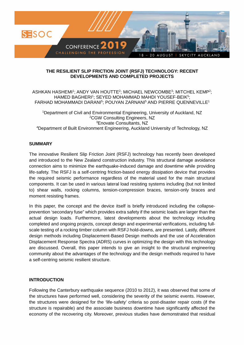
CASE STUDY – THE NELSON AIRPORT TERMINAL DESIGNED BY DUNNING THORNTON CONSULTANTS The new Nelson Airport Terminal needed to provide a gateway to the top of the South Island, so the brief was to create an iconic, lofty space that represented the local landscape. The design needed to be modular for future expansion of a growing tourism market, and locally sourced. The architectural response to this brief was to mirror the local Richmond Ranges, with an undulating timber roof that sits high above the ground. Glazing clads most of the façade.
The building is 3800 m2 of ground floor space for retail, seating, airline operations and facilities, with 1200 m2 of mezzanine area to provide office space and baggage handling areas. The roof consists of 7 repeated bays stretching over 100 metres along the site. This sits atop highly liquefiable ground in a high seismic hazard zone. The building is Importance Level 3 due to it’s function as an airport terminal (see Figure 2(a)).
Figure 2. The New Nelson airport terminal: (a) Constructed stage A of the new Nelson Airport
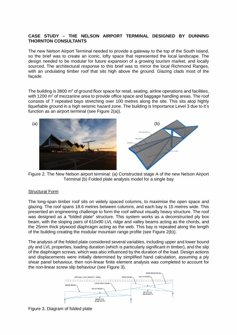
Terminal (b) Folded plate analysis model for a single bay Structural Form The long-span timber roof sits on widely spaced columns, to maximise the open space and glazing. The roof spans 18.6 metres between columns, and each bay is 15 metres wide. This presented an engineering challenge to form the roof without visually heavy structure. The roof was designed as a “folded plate” structure. This system works as a deconstructed ply box beam, with the sloping pairs of 610x90 LVL ridge and valley beams acting as the chords, and the 25mm thick plywood diaphragm acting as the web. This bay is repeated along the length of the building creating the modular mountain range profile (see Figure 2(b)). The analysis of the folded plate considered several variables, including upper and lower bound ply and LVL properties, loading duration (which is particularly significant in timber), and the slip of the diaphragm screws, which was also influenced by the duration of the load. Design actions and displacements were initially determined by simplified hand calculation, assuming a ply shear panel behaviour, then non-linear finite element analysis was completed to account for the non-linear screw slip behaviour (see Figure 3).
Figure 3. Diagram of folded plate
(a) (b)
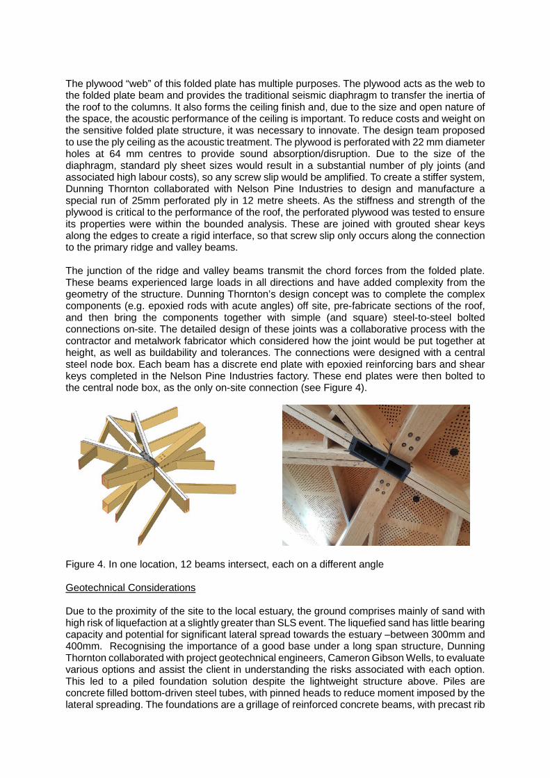
The plywood “web” of this folded plate has multiple purposes. The plywood acts as the web to the folded plate beam and provides the traditional seismic diaphragm to transfer the inertia of the roof to the columns. It also forms the ceiling finish and, due to the size and open nature of the space, the acoustic performance of the ceiling is important. To reduce costs and weight on the sensitive folded plate structure, it was necessary to innovate. The design team proposed to use the ply ceiling as the acoustic treatment. The plywood is perforated with 22 mm diameter holes at 64 mm centres to provide sound absorption/disruption. Due to the size of the diaphragm, standard ply sheet sizes would result in a substantial number of ply joints (and associated high labour costs), so any screw slip would be amplified. To create a stiffer system, Dunning Thornton collaborated with Nelson Pine Industries to design and manufacture a special run of 25mm perforated ply in 12 metre sheets. As the stiffness and strength of the plywood is critical to the performance of the roof, the perforated plywood was tested to ensure its properties were within the bounded analysis. These are joined with grouted shear keys along the edges to create a rigid interface, so that screw slip only occurs along the connection to the primary ridge and valley beams. The junction of the ridge and valley beams transmit the chord forces from the folded plate. These beams experienced large loads in all directions and have added complexity from the geometry of the structure. Dunning Thornton’s design concept was to complete the complex components (e.g. epoxied rods with acute angles) off site, pre-fabricate sections of the roof, and then bring the components together with simple (and square) steel-to-steel bolted connections on-site. The detailed design of these joints was a collaborative process with the contractor and metalwork fabricator which considered how the joint would be put together at height, as well as buildability and tolerances. The connections were designed with a central steel node box. Each beam has a discrete end plate with epoxied reinforcing bars and shear keys completed in the Nelson Pine Industries factory. These end plates were then bolted to the central node box, as the only on-site connection (see Figure 4).
Figure 4. In one location, 12 beams intersect, each on a different angle Geotechnical Considerations Due to the proximity of the site to the local estuary, the ground comprises mainly of sand with high risk of liquefaction at a slightly greater than SLS event. The liquefied sand has little bearing capacity and potential for significant lateral spread towards the estuary –between 300mm and 400mm. Recognising the importance of a good base under a long span structure, Dunning Thornton collaborated with project geotechnical engineers, Cameron Gibson Wells, to evaluate various options and assist the client in understanding the risks associated with each option. This led to a piled foundation solution despite the lightweight structure above. Piles are concrete filled bottom-driven steel tubes, with pinned heads to reduce moment imposed by the lateral spreading. The foundations are a grillage of reinforced concrete beams, with precast rib
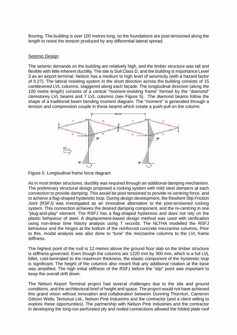
flooring. The building is over 100 metres long, so the foundations are post-tensioned along the length to resist the tension produced by any differential lateral spread. Seismic Design The seismic demands on the building are relatively high, and the timber structure was tall and flexible with little inherent ductility. The site is Soil Class D, and the building is Importance Level 3 as an airport terminal. Nelson has a medium to high level of seismicity (with a hazard factor of 0.27). The lateral resisting system in the short direction across the building consists of 15 cantilevered LVL columns, staggered along each façade. The longitudinal direction (along the 100 metre length) consists of a central “moment-resisting frame” formed by the “diamond” clerestorey LVL beams and 7 LVL columns (see Figure 5). The diamond beams follow the shape of a traditional beam bending moment diagram. The “moment” is generated through a tension and compression couple in these beams which create a push-pull on the column.
Figure 5. Longitudinal frame force diagram As in most timber structures, ductility was required through an additional damping mechanism. The preliminary structural design proposed a rocking system with mild steel dampers at each connection to provide damping. This would be post-tensioned to provide re-centring force, and to achieve a flag-shaped hysteretic loop. During design development, the Resilient Slip Friction Joint (RSFJ) was investigated as an innovative alternative to the post-tensioned rocking system. This connection achieves the desired damping component, and the re-centring in one “plug-and-play” element. The RSFJ has a flag-shaped hysteresis and does not rely on the plastic behaviour of steel. A displacement-based design method was used with verification using non-linear time history analysis using 7 records. The NLTHA modelled the RSFJ behaviour and the hinges at the bottom of the reinforced concrete mezzanine columns. Prior to this, modal analysis was also done to “tune” the mezzanine columns to the LVL frame stiffness. The highest point of the roof is 12 metres above the ground floor slab so the timber structure is stiffness-governed. Even though the columns are 1220 mm by 300 mm, which is a full LVL billet, cold-laminated to the maximum thickness, the elastic component of the hysteretic loop is significant. The height of the columns also meant that any additional rotation at the base was amplified. The high initial stiffness of the RSFJ before the “slip” point was important to keep the overall drift down. The Nelson Airport Terminal project had several challenges due to the site and ground conditions, and the architectural brief of height and space. The project would not have achieved this grand vision without innovation and collaboration between Dunning Thornton, Cameron Gibson Wells, Tectonus Ltd., Nelson Pine Industries and the contractor (and a client willing to explore these opportunities). The partnership with Nelson Pine Industries and the contractor in developing the long-run perforated ply and noded connections allowed the folded plate roof
to have light structure and loftiness. The development and integration of the RSFJ connection enhanced the seismic performance of the building, making the grand heights of the roof possible, while keeping the column sizes proportional to the space (and economical).
EXPERIMENTAL TESTING OF A ROCKING COLUMN WITH RSFJ HOLD-DOWNS RELATED TO THE NEW NELSON AIRPORT TERMINAL PROJECT
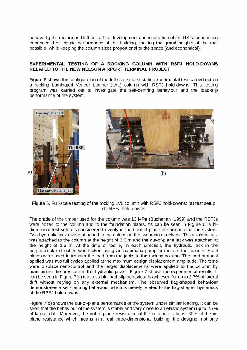
Figure 6 shows the configuration of the full-scale quasi-static experimental test carried out on a rocking Laminated Veneer Lumber (LVL) column with RSFJ hold-downs. This testing program was carried out to investigate the self-centring behaviour and the load-slip performance of the system.
Figure 6. Full-scale testing of the rocking LVL column with RSFJ hold-downs: (a) test setup (b) RSFJ hold-downs
The grade of the timber used for the column was 13 MPa (Buchanan 1999) and the RSFJs were bolted to the column and to the foundation plates. As can be seen in Figure 6, a bi-directional test setup is considered to verify in- and out-of-plane performance of the system. Two hydraulic jacks were attached to the column in the two main directions. The in-plane jack was attached to the column at the height of 2.6 m and the out-of-plane jack was attached at the height of 1.6 m. At the time of testing in each direction, the hydraulic jack in the perpendicular direction was locked using an automatic pump to restrain the column. Steel plates were used to transfer the load from the jacks to the rocking column. The load protocol applied was two full cycles applied at the maximum design displacement amplitude. The tests were displacement-control and the target displacements were applied to the column by maintaining the pressure in the hydraulic jacks. Figure 7 shows the experimental results. It can be seen in Figure 7(a) that a stable load-slip behaviour is achieved for up to 2.7% of lateral drift without relying on any external mechanism. The observed flag-shaped behaviour demonstrates a self-centring behaviour which is merely related to the flag-shaped hysteresis of the RSFJ hold-downs. Figure 7(b) shows the out-of-plane performance of the system under similar loading. It can be seen that the behaviour of the system is stable and very close to an elastic system up to 2.7% of lateral drift. Moreover, the out-of-plane resistance of the column is almost 30% of the in-plane resistance which means in a real three-dimensional building, the designer not only
The in-plane jack
(a) (b)
The out-of-plane jack
The RSFJ

benefits from the dis-placement compatibility of the system but also may be able to take this extra out-of-plane resistance into account.
Figure 7. Experimental results of the rocking LVL columns with RSFJ hold-downs: (a) in-
plane testing (b) Out-of-plane testing
CASE STUDY - A Timber Framed Building in Wellington The RSFJ technology has been implemented in a new two storey, timber framed, Importance Level 4 (IL4) building in Wellington. The seismic design procedure chosen to design the lateral system of the building was a mix of the Equivalent Static Method (ESM) and Nonlinear Static Pushover Analysis (NLSPA). The first mode dominant nature of the building and the regular layout of lateral structure made NLSPA the logical choice for verifying the buildings seismic performance. The building owner was particularly concerned about damage to drift sensitive components within the building, so target drift levels for the SLS1, SLS2, ULS, and MCE limit states were discussed and set early in the design process. Preliminary sizing of the lateral system and the RSFJ elements was completed by utilising a mix of hand calculations, linear-elastic models of the buildings, and the Equivalent Static Method. Equivalent static forces we derived for a ductility of 2.0, conservatively chosen (with guidance from Tectonus Ltd.) to represent realistically achievable levels of damping due to the flag-shaped hysteretic behaviour of the RSFJ elements. On completion of the preliminary design, required force-deformation data was given to Tectonus Ltd. to design their RSFJ elements. After finalising their design, the hysteretic data for each RSFJ was provided, meaning the RSFJ elements could easily be added to the structural model of the building, allowing the creation of a non-linear structural model. An example of the hysteretic curves provided by Tectonus for this project is shown in Figure 8.
Figure 8. Example flag-shape hysteretic curves for a 2050 kN RSFJ
Once the non-linear structural model had been developed, multiple NLSPA cases were run. Resulting pushover curves were exported and combined with Horizontal Acceleration-
-400
-300
-200
-100
0
100
200
300
400
-3 -2 -1 0 1 2 3
Forc
e (k
N) @
2.6
m
Drift (%)
-150
-100
-50
0
50
100
150
-3 -2 -1 0 1 2 3
Forc
e (k
N) a
t 1.8
m
Drift (%)
-2,500
-2,000
-1,500
-1,000
-500
0
500
1,000
1,500
2,000
2,500
-60 -50 -40 -30 -20 -10 0 10 20 30 40 50 60
Force, F (kN)
Displacement, ∆ (mm)
(a) (b)
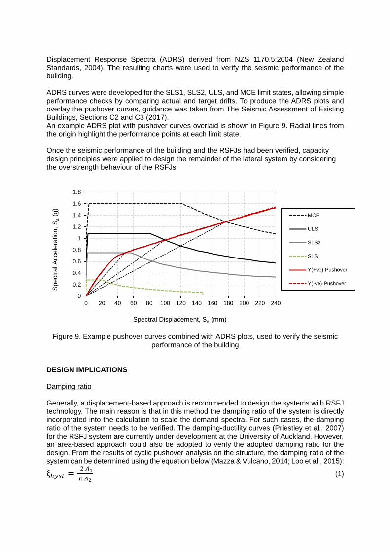
Displacement Response Spectra (ADRS) derived from NZS 1170.5:2004 (New Zealand Standards, 2004). The resulting charts were used to verify the seismic performance of the building. ADRS curves were developed for the SLS1, SLS2, ULS, and MCE limit states, allowing simple performance checks by comparing actual and target drifts. To produce the ADRS plots and overlay the pushover curves, guidance was taken from The Seismic Assessment of Existing Buildings, Sections C2 and C3 (2017). An example ADRS plot with pushover curves overlaid is shown in Figure 9. Radial lines from the origin highlight the performance points at each limit state. Once the seismic performance of the building and the RSFJs had been verified, capacity design principles were applied to design the remainder of the lateral system by considering the overstrength behaviour of the RSFJs.
Figure 9. Example pushover curves combined with ADRS plots, used to verify the seismic performance of the building
DESIGN IMPLICATIONS Damping ratio
Generally, a displacement-based approach is recommended to design the systems with RSFJ technology. The main reason is that in this method the damping ratio of the system is directly incorporated into the calculation to scale the demand spectra. For such cases, the damping ratio of the system needs to be verified. The damping-ductility curves (Priestley et al., 2007) for the RSFJ system are currently under development at the University of Auckland. However, an area-based approach could also be adopted to verify the adopted damping ratio for the design. From the results of cyclic pushover analysis on the structure, the damping ratio of the system can be determined using the equation below (Mazza & Vulcano, 2014; Loo et al., 2015):
ξℎ𝑦𝑦𝑦𝑦𝑦𝑦 = 2 𝐴𝐴1π 𝐴𝐴2
(1)
0
0.2
0.4
0.6
0.8
1
1.2
1.4
1.6
1.8
0 20 40 60 80 100 120 140 160 180 200 220 240
Spec
tral A
ccel
erat
ion,
Sa
(g)
Spectral Displacement, Sd (mm)
MCE
ULS
SLS2
SLS1
Y(+ve)-Pushover
Y(-ve)-Pushover

Figure 10. Verification of the damping ratio using the area-based approach
Acceleration-Displacement Response Spectra (ADRS) Curves An efficient way to design the systems with flag-shape response is the use of the Acceleration-Displacement Response Spectra (ADRS) curve to specify the Fslip and Fult of the system based on the scaled and unscaled demand curves. In this approach, the SLS1 or SLS2 (depending on the importance level of the structure) would determine the Fslip of the system or in other words, the threshold in which the first RSFJ in the system starts to open. On the other hand, the ULS demand curve which is scaled based on the damping ratio determines the Fult of the system before the secondary fuse starts to activate. Figure 11 illustrates the approach described to specify the performance points of the structure.
Figure 11. Verification of the damping ratio using the area-based approach The collapse-prevention secondary fuse The RSFJ is designed in a way that all components remain elastic up to the design load (Fult of the device). However, with the aim of collapse prevention in cases that the applied loads are higher than the design earthquake loads, a collapse-prevention secondary fuse in the body of the RSFJ is considered. When the load on the RSFJ increase beyond its maximum capacity (Fult), the clamping bolts (or rods) start to yield. The inelastic elongation of the bolts provides additional travel distance for the joint allowing it to maintain a ductile behaviour (without the device locking at any stage) up to 1.5 times of the design displacement.
0
0.1
0.2
0.3
0.4
0.5
0.6
0.000 0.050 0.100 0.150 0.200
Acce
lera
tion
(g)
Displacement (m)
ADRS CurveScaled ADRS CurveWind or SLS
Devices before expansion
(0.33% drift?)
Devices at full expansion
(1% to 1.5% drift?)
The target bi-linear performance curve
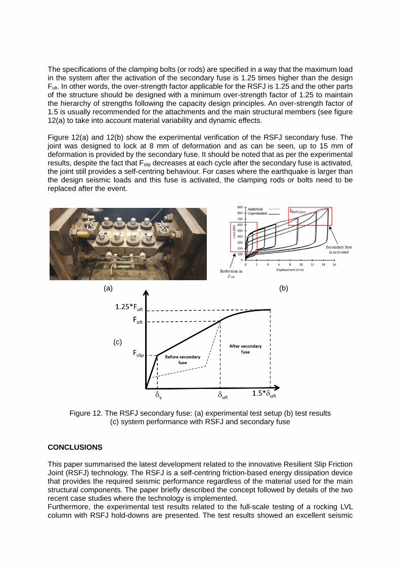
The specifications of the clamping bolts (or rods) are specified in a way that the maximum load in the system after the activation of the secondary fuse is 1.25 times higher than the design Fult. In other words, the over-strength factor applicable for the RSFJ is 1.25 and the other parts of the structure should be designed with a minimum over-strength factor of 1.25 to maintain the hierarchy of strengths following the capacity design principles. An over-strength factor of 1.5 is usually recommended for the attachments and the main structural members (see figure 12(a) to take into account material variability and dynamic effects. Figure 12(a) and 12(b) show the experimental verification of the RSFJ secondary fuse. The joint was designed to lock at 8 mm of deformation and as can be seen, up to 15 mm of deformation is provided by the secondary fuse. It should be noted that as per the experimental results, despite the fact that Fslip decreases at each cycle after the secondary fuse is activated, the joint still provides a self-centring behaviour. For cases where the earthquake is larger than the design seismic loads and this fuse is activated, the clamping rods or bolts need to be replaced after the event.
Figure 12. The RSFJ secondary fuse: (a) experimental test setup (b) test results (c) system performance with RSFJ and secondary fuse
CONCLUSIONS This paper summarised the latest development related to the innovative Resilient Slip Friction Joint (RSFJ) technology. The RSFJ is a self-centring friction-based energy dissipation device that provides the required seismic performance regardless of the material used for the main structural components. The paper briefly described the concept followed by details of the two recent case studies where the technology is implemented. Furthermore, the experimental test results related to the full-scale testing of a rocking LVL column with RSFJ hold-downs are presented. The test results showed an excellent seismic
(a) (b)
(c)
performance and a fully self-centring behaviour while all component of the system remained elastic. Finally, different design implications regarding this technology were discussed including the appropriate over-strength factor that needs to be considered for the capacity design. Overall, this paper gives an insight to the structural engineering community about the RSFJ technology, design methods and its implementation. ACKNOWLEDGMENT The authors would like to thank Ministry of Business, Innovation and Employment of New Zealand (MBIE) for the financial support of the research conducted. Also, they would like to acknowledge Alistair Cattanach, Matt Davis and Jaimie Whitehead at Thornton Consultants for their contribution in preparation of the material for this paper. Furthermore, the contribution of CGW Consulting Engineers and Enovate Consultants is appreciated. REFERENCES Bruneau, M., & MacRae, G. (2017). Reconstructing Christchurch : A Seismic Shift in Building
Structural Systems. Quake Centre Report. Buchanan, A. H., & Federation, N. Z. T. I. (1999). Timber design guide. New Zealand Timber
Industry Federation. Hashemi, A., Zarnani, P., Masoudnia, R., & Quenneville, P. (2017). Seismic resistant rocking
coupled walls with innovative Resilient Slip Friction (RSF) joints. Journal of Constructional Steel Research, 129. https://doi.org/10.1016/j.jcsr.2016.11.016
Hashemi, A., Zarnani, P., & Quenneville, P. (2018). Developement of Resilient Seismic Solutions for Timber Structures using the Resilient Slip Friction Joint (RSFJ) Technology. World Conference of Timber Engineering WCTE2018, Seoul, Republic of Korea.
Loo, W. Y., Quenneville, P., & Chouw, N. (2015). Rocking Timber Structure with Slip-Friction Connectors Conceptualized As a Plastically Deformable Hinge within a Multistory Shear Wall. Journal of Structural Engineering, E4015010.
Mazza, F., & Vulcano, A. (2014). Equivalent viscous damping for displacement-based seismic design of hysteretic damped braces for retrofitting framed buildings. Bulletin of Earthquake Engineering, 12(6), 2797–2819.
New Zealand Standards. (2004). Structural Design Actions (NZS 1170.5). Wellington, New Zealand.
NZSEE. (2017). Seismic Assessment of Existing Buildings. Priestley, M. J. N., Calvi, G. M., & Kowalsky, M. J. (2007). Direct displacement-based seismic
design of structures. 2007 NZSEE Conference. Zarnani, P., & Quenneville, P. (n.d.). A Resilient Slip Friction Joint. Zarnani, P., Valadbeigi, A., & Quenneville, P. (2016). Resilient Slip Friction (RSF) Joint: A Novel
Connection System for Seismic Damage Avoidance Design og Timber Structures. World Conference of Timber Engineering WCTE2014, Vienna, Austria.