the rig stand for testing integrated...
TRANSCRIPT

Journal of KONES Powertrain and Transport, Vol. 23, No. 4 2016
THE RIG STAND FOR TESTING INTEGRATED ROCKET RAMJET ENGINE
Artur Rowiński
Institute of Aviation Krakowska Avenue 110/114, 02-256 Warsaw, Poland
tel.: +48 22 8460011, fax: +48 22 8464432 e-mail: [email protected]
Abstract
Integrated rocket ramjet engine is adapted to aircraft propulsion and supersonic missiles moving at the speed of 8 Ma. The engine’s construction enables flexibly benefit from both types of drive depending on the conditions of the flight. The ejector mode of operation applicable to Mach numbers smaller than 2 cooperate with the rocket engine positioned in flow channel. Secondary air stream enters the engine through the convergent divergent nozzle and supplies the air to the ejector and booster. Rocket engine using the ejector effect would be used only in the phase of accelerating an object to the supersonic speed and then the drive would gradually shift to ramjet. The range of speed for the ramjet mode is 2-6 Mach.
The prototype of the rocket ramjet engine of over 1300 N is equipped with annular combustion chamber in which phenomena of rotating detonation as well as the aero spike nozzle were used. Both the test stand as well as the engine is adapted to trials suitable to the conditions of a flight at the speed of 1.4 Ma. The test stand is powered by compress air coming from the instalment set up in the earth test bed and by oxygen and methane at a pressure of 10 bar. The rig is designed for functional tests of prototype, areas of the creation of mixture of firearms used to measuring and the range of stable functioning of the engine in the ramjet mode. Moreover, the measured parameters in gas supply installations as well as the temperature and pressure in the combustion chamber and thrust created by integrated rocket ramjet engine are measured.
Keywords: turbine engine, combustion chamber, detonation combustion, rotating detonation engine (RDE)
1. Introduction
Since 2009, the Institute of Aviation has been developing a project called “Turbine engine witha detonation combustion chamber” under the Innovative Economy program. In the aforementioned project a combustion chamber was used, in which a higher total pressure – and thus higher efficiency of heat circulation (Ficket-Jacobs’s cycle corresponding to detonation combustion) – as compared to Brayton’s “classical” cycle (deflagration combustion) (Fig. 1) was obtained as an effect of detonation combustion. Research conducted on the phenomenon of spinning detonation took place on a rig powered by compressed air from the main pipeline of a compressed air installation both in combustion chambers as well as in a can combustion chamber assemble [1, 2, 4]. Annular chambers of different inner geometry were used for the tests. Additionally, tests under various levels of chamber choking and various pressures within the combustion chamber were conducted for each geometry. Research, of the rotating detonation phenomena, was carried out for a number of detonation chambers with different interior channel geometry. In addition, for each geometry configuration, tests were carried out for different levels of dumping of the chamber outlet and hence for different pressures conditions inside the detonation chamber. During these tests, parameters such as pressure behind the detonation wave (using piezoelectric sensors), the static pressure in front of and inside the detonation chamber and temperature: before, inside and at the outlet of the chamber, were measured. Research was performed for the various mass flow rates of air and fuel injected into the chamber, that means for the different air-fuel equivalence ratios (Lambda). The main achievement of this study was to obtain a stable and reproducible rotating
ISSN: 1231-4005 e-ISSN: 2354-0133 DOI: 10.5604/12314005.1217261
A. Rowiński
detonation of air and heated kerosene (Jet-A) mixture, thus the results presented in this paper presents mainly these tests as the most interesting to the reader. The growth of the assembly thermodynamic cycle is estimated at 10% [5].
Fig. 1. Comparison of thermodynamic cycle with deflagration combustion (isochoric Humphrey’s, isobaric
Brayton’s), and detonation combustion (Fickett-Jacobs’) [3]
a
b Fig. 2. Integrated rocket-ramjet engine (a) and the flow of gas through combustion chamber during detonation in
such an integrated rocket ramjet engine (b)[6]
A proposal for a new, unique integrated rocket-ramjet engine, which employs a rocket engine with a detonation chamber, was developed based on the acquired experience (Fig 2). The system allows for three modes of operation to be applied: ejector, rocket and ramjet. The appropriate mode of operation is turned on depending on flight conditions, making full use of its advantages. Such an engine may operate in different modes depending on flight altitude and the Mach number. The ejector mode applies to Mach numbers smaller than 2 and it cooperates with rocket engine. The rocket engine employing the ejector mode of operation would be used exclusively at the stage of accelerating an object to supersonic speed, and then propulsion system would gradually switch to ramjet propulsion. The scope of velocity for ramjet mode of operation is between 2 and 6 Mach. In this mode, the rocket engine is turned off or works at low parameters. In the supersonic mode, when the Mach number is between 6 and 8, supersonic combustion takes place in the flow passage
422

The Rig Stand for Testing Integrated Rocket Ramjet Engine
The rocket mode of operation may be turned on again when the Mach number is over 8 [6]. Such an engine, equipped with annular combustion chamber and an aerospike nozzle, may naturally shift from the rocket mode of operation to the ramjet mode and vice versa. In the rocket mode an engine would operate using liquid hydrocarbon fuel and liquid oxidizer (liquid oxygen, liquid air, hydrogen peroxide etc.), while in the ramjet mode it would use initial combustion in the annular combustion chamber enriched with a mixture of compressed air and hydrocarbon fuel. The afterburning of the products of partial combustion enriched with fuel would take place in the ramjet section of the engine. Such an engine operating in different modes is pictured in Fig. 2.
The integrated propulsion system might be applied to the future supersonic transport airplanes or hypersonic missiles designed for the transportation of warheads as well as for combating the enemy’s planes and rockets. Such a solution will help decrease the costs of the engine’s production and exploitation by eliminating the turbine engine form the assembly and by expanding the limits of its operative capabilities with regards to velocity and altitude of the flight. 2. Design of a rig for engine tests
The test rig is designed to measure the thrust of the integrated rocket ramjet engine, with the thrust of 1300 N, as well as to measure the parameters of gases in support systems and fumes in the combustion chamber of a ramjet engine. A ramjet engine is powered by compressed air delivered from the installation built in earth testbed. The rig was designed so that the air parameters (static pressure, temperature and velocity in the inlet cross-section to the combustion chamber) would correspond to the analogous parameters, which are reached during a flight at a 1.5 Ma velocity. Thus, the air in the pipeline is initially heated up to the temperature of 130°C. The compressed air assemble is connected to the inlet of the engine by a compensator with a low lateral stiffness (6). Such a solution enables the engine to turn round the axis shaft (2) due to the thrust and it allows for the measurement of the pressure force of the lever arm, which is fastened to the hull of the engine, upon the force sensor.
The test rig is composed of a base (1), a shift and bearing system and an arm (8, Fig. 3), an inlet system of the compressed air (including: a modernized assembly of a case and of a flame tube of the RDE combustion chamber), flexible pressure tube (6), lever shield of the assembly of thrust measurement (8) along with the adaptor cover of tube connectors of the oxygen and methane installation (13), ramjet engine’s assembly of the flame tube (2) and (4), assembly of outlet nozzle (5) including a nozzle (10) and a base shield (12). There are seven slots on the outer surface of the flame tube. The construction of the slots enables the sealing of a pipe passage after placing the connectors inside the rig.
The ignition system consists of two ignition plugs (18) placed in the slots on the outer surface (2) of the flame tube. The plugs are located in sleeves (25 and 26). These elements enable the plugs to be installed as well as to establish the depth of their positioning within the combustion chamber and to protect the part of the plug placed in the combustion chamber from the temperature’s influence. The connection with the slot is sealed by an elastic washer (24). The case of the quartz high temperature pressure sensor Kistler type 606B is installed in the slot (19) [5]. The elements that are highly heat-loaded, that is: the assembly of the flame tube (2, 18) and the slots are made of heat-resistant steel. The elements of the assemblies (5), (3) and (4, 6, 12, 10) and made of stainless steel.
The rocket engine fuel system consists of installations, which deliver methane and oxygen in their gas forms to the mixing chamber. Both installations are made of the same elements. The composition of the combustible mixture is established by the pressure on in fuelling tanks (12 and 14). The tanks are connected to a vacuum pump (4) before they are filled. The gas from main tanks is transported to the empty tanks through pressure reducers (7 and 8) and valve systems (5 and 6). The level of pressure in particular tanks is controlled by assemblies of manometers placed in the aforementioned systems. After closing valves Z1 and Z4 and opening valves Z3 and Z6 the gasses
423

A. Rowiński
are delivered to solenoid valves (9 and 10); then – after they are turned on by measuring systems (11 and 12) – the gasses are delivered to the engine’s mixing chamber, and then to the combustion chamber through the calibrating openings (Fig. 4)
a) b)
c)
Fig. 3. Sketch of a rig adapted to the fastening of a rocket ramjet engine
Gas (oxygen, methane) is delivered to the measurement space of the system through an opening in a joint (4) to the case (6) where a washer is located; this washer has an opening designed for securing an unobstructed flow in the area where absolute and static pressure are measured. The measurement is carried out with the Prantle probe (1). There is also a “K” thermocouple (2) located in the measurement space.
The solenoid valves along with the two ignition plugs are controlled by the terminal. The terminal regulates the time of turning on and off the solenoid valves, and the time of igniting the plug.
424

The Rig Stand for Testing Integrated Rocket Ramjet Engine
Fig. 4. A scheme of the fuel system as well as the regulation system and the acquisition of data for the rocket engine.
The measurement chain is marked with color blue, signal chain with color red; T_M – total temperature of methane; T_O – total temperature of oxygen; P_dM – dynamic pressure of methane; P_sM – static pressure of methane; P_dO – dynamic pressure of oxygen; P_sO – static pressure of oxygen; Pc-Ks – pressure in the combustion chamber
Fig. 5. Block scheme of data acquisition and control system
425

A. Rowiński
The application installed on the terminal allows for the timing of all the devices included in the fuel system as well as the integrated rocket ramjet engine.
Control and data acquisition system The system controls the duration of the experiment as well as the times of the opening and
closing of the solenoid valves, which supply compressed air and methane to the chamber. The acquisition and full visualization of electric signals showing the measured parameters are allowed by the program “ENGINE TEST STAND_11.” It was assumed, that all the measured parameters will be read and registered (Fig. 5).
The elements of the measurement system: 1. Thermocouple type “K” of low measurement inertia. 2. Fast piezoelectric pressure sensors – KISTLER type 601A and type 603B. 3. Laboratory charge amplifiers – KISTLER type 5018A1000 (cooperating with piezoelectric
dynamic pressure sensors). 4. Pressure sensors – SEN-3247B075 with the range up to 10 bar: − Measurement chart National Instruments NI-PCI-6259 equipped with a fast analog-to-digital
converter serves to acquire electric signals and a two-way communication with the surroundings by using the Lab View software from National Instruments,
− Terminal National Instruments NI-SCC-68 (4 temperature measurement channels and 8 voltage channels) a set of inputs and outputs, powered by a computer or a outside source, used to join the measurement chart with the source of analogue signals. It is equipped with four dedicated circuits SCC (Signal Conditioning Slots) which serve as inputs (depending on the type): thermocouple, strain gauge, thermal resistance, frequency, force meter etc.,
− Modules specialized for temperature measurement: SCC-TC02 – 4 pcs, − Measurement chart National Instruments NI-USB-6259 used to measure fast-changing voltage
signals, − Pressure transmitters for ranges up to 10 bar – 4 pcs, − Control and power module consists of a case with executive modules.
The role of the control and power module is to enable the control of low current signals from the measurement chart (5V, 10mA), of actuators (valves, switches etc.) (24V, 3A). 3. The results obtained
The test rig described in the article was designed and made but no functional tests of the engine
working in the ramjet mode were carried out. The results of such tests as maps of pressure and mass flow of methane and oxygen in the supporting installation (Fig. 6 and 7) and total pressure in the combustion chamber (Fig. 8) presented below refer to tests of a rocket engine, which is a subassembly of an integrated rocket-ramjet engine. The gas and fumes parameters were measured for various combustible mixtures of either enriched or impoverished content.
Tab. 1 Contents of combustible mixture
Lp. P stat. O2 [bar]
P stat. OCH4 [bar]
The timing of ignition delay [ms]
The timing of valve opening [s] Ignition Rotating
detonation 1. 10 5 400 2.5 + + 2. 10 5 100 1.5 + + 3. 10 4 400 1.5 + + 4. 10 3.2 400 1.5 + + 5. 10 2.8 200 1.5 + - 6. 10 2 400 2.0 + - 7. 10 1.5 500 2.0 + -
426
The Rig Stand for Testing Integrated Rocket Ramjet Engine
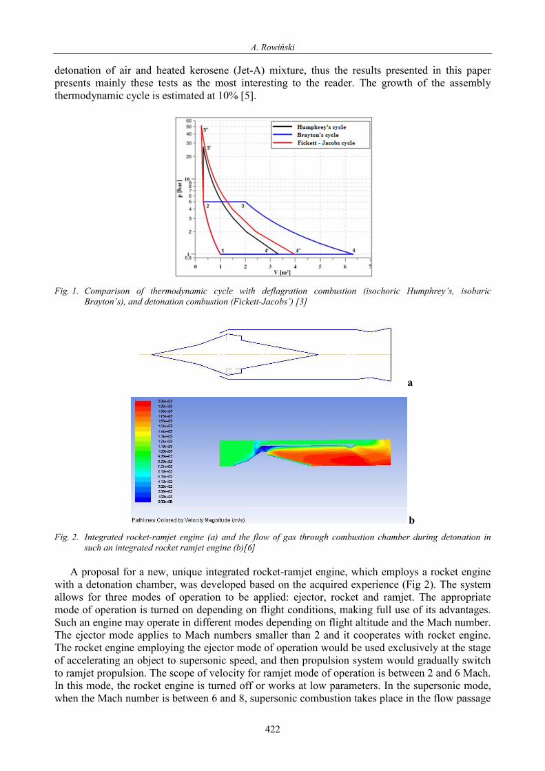
Fig. 6. Static pressure of oxygen and methane
Fig. 7. Mass flow of oxygen and methane
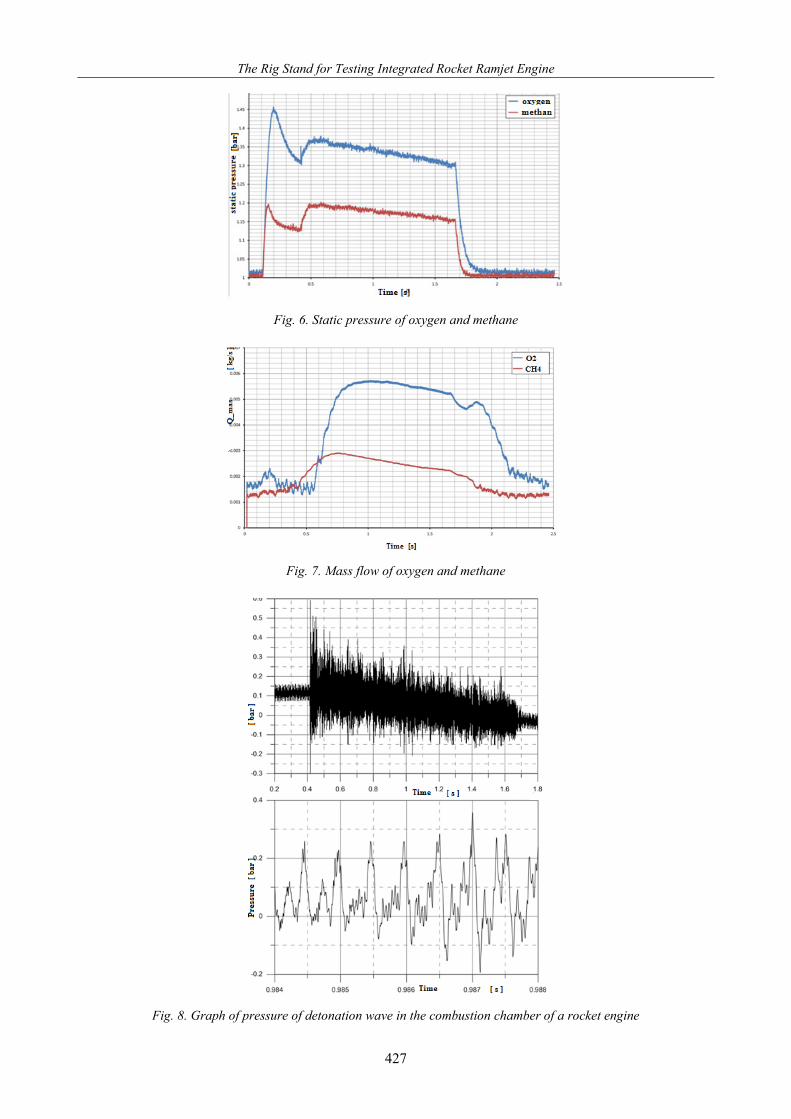
Fig. 8. Graph of pressure of detonation wave in the combustion chamber of a rocket engine
427

A. Rowiński
Fig. 9. FFT analysis of the measured signal of pressure
4. Conclusions
1. The phenomenon of ignition and combustion of methane and oxygen mixture (within the range presented in Fig. 1), in the process of rotating detonation occurs in the combustion chamber of rocket engine (the velocity of detonation wave for combustible mixture of methane and oxygen at the stechiometric ratio reaches ca 1300 m/s (Fig. 9). The rocket engine produces thrust in the process of detonation combustion.
2. The supporting system of rocket engine is efficient and hermetic at methane and oxygen inner pressure up to 10 bar. The rocket engine produces thrust in the process of detonation combustion.
3. Measure and data acquisition system measures and registers static and total pressures, static temperatures of gasses, fast-changing pressures of fumes in a shock wave of rotating detonation in the combustion chamber and the thrust of the engine.
4. The thrust measure system is efficient and is not distorted when charged with the force perpendicular to the surface of the arm, up to 200 N. The registered measurements of force are repeatable.
References
[1] Bykovskij, F. A., Zhdan, S.A., Vedernikov, E., F., Continuous spin detonation in ducted
annular combustors, Application of detonation to Propulsion, edited by Torus Press, 2004. [2] Kailasanath, K., Review of Propulsion Applications of Detonation Waves, AIAA Journal,
Vol. 38, No. 9, 2000. [3] Kindracki, J., Badania eksperymentalne i symulacje numeryczne procesu inicjacji wirującej
detonacji gazowej, PhD dissertation, MEiL, Politechnika Warszawska, Warszawa 2008. [4] Kindracki, J., Wolanski, P., Gut, Z., Experimental Research on the Rotating Detonation in
Gaseous Fuels-Oxygen Mixtures, Shock Waves, Vol. 21, No. 2, pp. 75-84, 2011. [5] Łukasik, B., Czyż, S., Irzycki, A., Rowiński, R., The Study of the Continuously Rotating
Detonation Combustion Chamber Supplied with Different Types of Fuel, Journal of KONES, Vol. 20, No. 3, Warsaw 2013.
[6] Wolański, P., Koncepcja nowego silnika odrzutowego o spalaniu detonacyjnym, Progress in Astronautics, T. 29, Nr 1, 2006.
428