the risk analysis applied to deep tunnels 186 design el ... · design—el teniente new mine level...
TRANSCRIPT

186The Risk Analysis Applied to Deep TunnelsDesign—El Teniente New Mine Level AccessTunnels, Chile
Lorenzo Paolo Verzani, Giordano Russo, Piergiorgio Grasso,and Agustín Cabañas
AbstractEl Teniente Mine, with 2,400 km of tunnels excavated since the beginning of the last Centuryis the largest underground copper mine in the world. El Teniente Mine production plan has athin overlap between the exhaustion of the current production level and the activation of theNew Mine Level, located at almost 1,000 m depth, planned for 2017. The infrastructuresystem involves the construction of 24 km of access tunnels, consisting of two adits, a tunnelfor vehicular access of personnel and a twin conveyor tunnel for the transport of the ore. Thedefinition of geological and geomechanical scenarios, as predicted on the basis of the referencemodels, and the related hazards identification and mitigation (following a risk analysis baseddesign), are cornerstones along the production chain. Tunnel alignment intersects a complexgeological environment characterized by rock variability: from igneous (effusive and intrusive)to sedimentary volcanoclastic rocks, with sectors of intense hydrothermal alteration. Due tohigh overburden and variability of rock mass properties, geomechanical hazards such assqueezing and rockburst are expected, together with caving and flowing-ground conditionscrossing fault sectors associated with high hydraulic pressures. This paper synthesizes thedesign methodology, focused on risk management (Risk Analysis-driven Design, Geodata2009). The construction of the tunnel is actually in process and then also a preliminarycomparison “predicted versus observed” is anticipated.
KeywordsRisk management plan � Risk analysis-driven design � Probabilistic reference scenarios �Hazards mitigation measures
186.1 Introduction
El Teniente Mine, located in the Libertador General Ber-nardo O’Higgins Region 80 km southeast of Chile’s capitalSantiago, is the largest underground copper mine in theworld, with 2,400 km of deep tunnels producing more than400,000 tons per year of fine copper.
El Teniente Mine production plan has a thin overlapbetween the exhaustion of the current production level andthe activation of the New Mine Level (NML), located atalmost 1,000 m depth, planned for 2017. The undergroundinfrastructures are under construction; the NML will extendlife of the mine by 50 years; a deeper level has beeninvestigated at 1,400 m depth (Fig. 186.1).
L.P. Verzani (&) � G. Russo � P. GrassoGeodata Engineering S.p.A., Turin, Italye-mail: [email protected]
G. Russoe-mail: [email protected]
P. Grassoe-mail: [email protected]
A. CabañasDivisión El Teniente, Corporación Nacional del Cobre de Chile(Codelco), Santiago, Chilee-mail: [email protected]
G. Lollino et al. (eds.), Engineering Geology for Society and Territory – Volume 6,DOI: 10.1007/978-3-319-09060-3_186, © Springer International Publishing Switzerland 2015
1023

The NML project foreseen the construction of 24 km ofaccess tunnels, consisting of two adits (Ltot = 6 km) and twomain tunnels (Ltot = 9 + 9 km): a tunnel for vehicular accessof personnel and a twin conveyor tunnel for the transport ofthe ore. Geodata Engineering (GDE), as a consultant ofCodelco and tunnels Contractor’s counterpart on geotech-nical issues, has been present on site since April 2012.
Prior to the construction phase, Geodata Engineering(GDE in association with Ingeroc) developed for Codelco adesign for the two main tunnels, based on the risk analysis(Risk Analysis-driven Design, RAdD) as reference for theowner about engineering solutions and construction costsand time assessment. Conventional and mechanized exca-vation methodologies were analyzed.
Constructora de Túneles Mineros–joint venture betweenSoletanche Bachy and Vinci (CTMSA) won proposing theconventional method (D&B), with two additional adits toincrease the number of parallel advances along the mainaccess tunnels (Fig. 186.2). Actually the constructions ofboth the main access tunnels and the adits are in process.
186.2 Risk Analysis-Driven Design (RAdD)
The design and construction of long tunnels particularlythose at great depth, is generally associated with a high levelof risks due to a whole series of uncertainties involved. Therisk management approach consists in identifying and listing
Fig. 186.1 Mine levels (byCodelco)
Fig. 186.2 NML tunnel accesssystem (by CTMSA)
1024 L.P. Verzani et al.
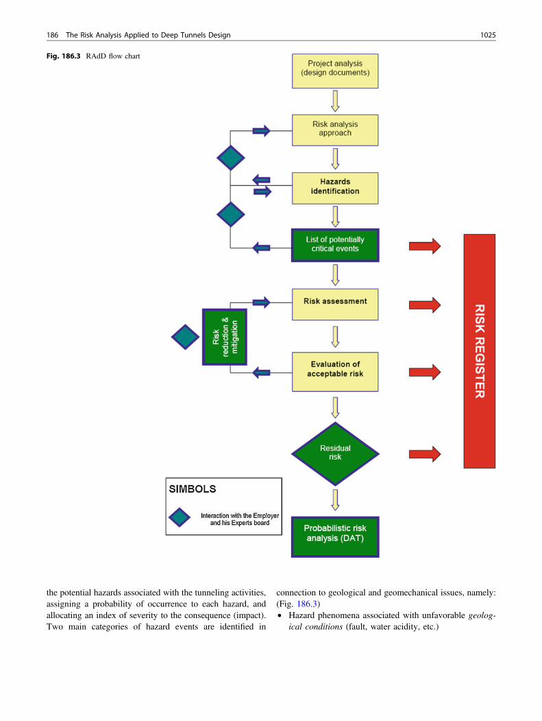
the potential hazards associated with the tunneling activities,assigning a probability of occurrence to each hazard, andallocating an index of severity to the consequence (impact).Two main categories of hazard events are identified in
connection to geological and geomechanical issues, namely:(Fig. 186.3)• Hazard phenomena associated with unfavorable geolog-
ical conditions (fault, water acidity, etc.)
Fig. 186.3 RAdD flow chart
186 The Risk Analysis Applied to Deep Tunnels Design 1025

• Geomechanical hazard related to rock mass behaviourupon excavation (squeezing, rockburst, etc.).The risk (R) is defined as the product of the probability of
occurrence of the hazard (P) and the related impact (I):R = P*I. In cases where the initial risk (i.e. the risk to whichthe project is exposed in absence of any mitigation measure)level is not acceptable, the relevant mitigating measuresshould be identified and designed.
After application of the mitigation measures, an analysisshould be performed to reassess the remaining risk level,obtaining an updated risk level, which is called the “residualrisk level”. It should be examined for acceptance as themaximum risk level that is to be confronted with its “globalcost”, necessary for reducing or completely eliminating therisk itself.
All the relevant information about the hazards, the asso-ciated risks and counter measures are filled and regularlyreviewed in a risk register.
186.3 Geological Setting and Related Risks
The regional geology of El Teniente area is characterized byvolcanic rocks and sedimentary volcanoclastic deposits, withfelsic to intermediate intrusive. As shown in the GeologicalReference Model, proceeding from West (portal) to East
(mine), the following lithological formations and Rock MassUnit (RMU) would be crossed:• Farellones Formation lower and undifferentiated mem-
bers (FFm, RMU.V1-V2)• Agua Amarga Hydrotermal Alteration and Breccia
(RMU.AA)• Sewell intrusive Complex (CSW, RMU.i1-CQ-i2)• El Teniente Mafic Complex (CMET, RMU.i3)• Braden Breccia (RMU.BB).
The tunnel axis crosses three major faults (F1, F2) and alarge number of minor faults (F4). Moreover the El Tenienteshear zone (F3) is foreseen along CSW and CMET forma-tions. On the basis of the Geological Reference Report (GRRCodelco-Hatch 2009), some potential geological hazardswere identified. Among them, the main ones in terms ofimpact are: geological structures, hydraulic load and waterpH, natural stress field and anisotropy, rock weathering andhydrothermal alteration (Fig. 186.4).
Moreover some additional hazards were analyzed for themechanized method (TBM): rock hardness-abrasiveness andheterogeneity. The main geological hazards are probabilisti-cally quantified and the risk register is compiled, both forD&Band TBM, considering the required mitigation measures foreach potential risk. Since March 2012, the following geome-chanical units have been excavated: RMU.V1 andRMU.V2 inFFm (main tunnels and Adit 1); the structural contact RMU.V2/AA (Adit 1) and RMU.I2 in CSW (Adit 2).
Fig. 186.4 Geological setting
1026 L.P. Verzani et al.

Fig. 186.5 GD Classification(Notes Russo and Grasso (2007);δ0 = radial deformation at theface; Rpl/R0 = palstic radius/radius of the cavity; σθ = maxtangential stress; σcm = rock massstrength. The limits of shadowzones are just indiactive) of theexcavation behaviour
Fig. 186.6 Design scatterdiagrams (RMU.V1)
Fig. 186.7 Hazard probability/intensity (RMU.V1-V2)
186 The Risk Analysis Applied to Deep Tunnels Design 1027

Fig. 186.8 Hazards frequency:probabilistic results for the n.3scenarios of reference (9 km inpersonnel tunnel)
GEOMECHANICAL HAZARDS (EXCAVATION BEHAVIOUR AND LOADING CONDITION RELATED)
Gravity driven instability
B1 ROCK BLOCK FALL ( OVERBREAKS) 5 2 10 1 5M01,M02,M23
,M24M01,M22,M23
,M24
B2 CAVING ( FACE / CAVITY COLLAPSE) 4 3 12 2 8M01,M02,M03,M06,M07,M0
8,M24
M01,M08,M22,M24,M25,M2
7
Stress induced instability
B3 ROCKBURST 2 3 6 2 4M1,M2,M21,M23,M26,M27
M01,M22,M23,M26
B4 SQUEEZING, FACE EXTRUSION 2 3 6 4 8M01,M02,M05,M07,M21,M2
4,M25,M27
M01,M22,M25,M27
Mainly water influenced (fault zone)
B5 FLOWING GROUND 5 5 25 5 25M01,M02,M06,M07,M08,M2
4
M01,M08,M22,M25,M27
B6 WATER INRUSH 5 5 25 5 25M01,M02,M06,M07,M08,M2
4
M01,M08,M22,M25,M27
B7 PIPING 5 5 25 5 25
Hazard identificationPrimary risk Mitigation measures*
CATEGORYSub-category
Hazard Probab.
[P]
D&B
HAZARD
TBM*or cross-reference to
geomechanical hazard [ ]
TBMD&B
TYPESub-type
Impact[I]
Risk[R=PxI]
Impact[I]
Risk[R=PxI]
M01,M02,M06
Fig. 186.9 Risk register (RMU.V2)
1028 L.P. Verzani et al.

186.4 Geomechanical and Residual Risks
The first step for RAdD is the geotechnical characterizationof the different RMU. Related to the available information,the statistical analysis has adopted different approaches inorder to define, in a probabilistic way, the three referencescenarios as geomechanical inputs for design: the most-likely scenario (from previous studies: H_lik), the favorableand the unfavorable ones (by data processing: GDE_fav/unf). Geomechanical hazards are mainly related to groundbehaviour upon excavation, thus taking into account theintrinsic properties of rock masses and the associated stressconditions.
The reference classification of the excavation behaviour isbased on both stress and geo-structural type analysis (matrixin Fig. 186.5), in the theoretical hypothesis of absence of anydesign interventions (→primary risk).
An example of the resulting design scatter diagrams ispresented for one of the rock mass unit excavated in thepersonnel tunnel (RMU-V1, Fig. 186.6). The assessment ofthe geomechanical risks is obtained with reference to theoccurrence probability and intensity of the related hazards.Along RMU V1 and V2, mainly geomechanical hazards dueto gravity, as wedge instability, are expected (Figs. 186.7and 186.8). The risk analysis proceeds with the initial riskassessment. Its evaluation involves the estimate of thepotential impact (consequence) deriving from the damagesrelated to the identified hazards. The Risk Register(Fig. 186.9) is consequently compiled for each RMU, bothfor the D&B and the TBM methods. The type and thedimensioning of the stabilization measures will be directlyrelated to the hazards and their potential impact on tunneling(→primary risk). The adequate mitigation measures (designsolutions) are consequently individuated, concurring to thecomposition of the different Section Types, dimensioned and
Fig. 186.10 RMU-V1, results of the geomechanical classification at tunnel face by the method of GDE multiple graph (Russo 2009)
186 The Risk Analysis Applied to Deep Tunnels Design 1029

probabilistically distributed along the tunnels. The last stepfor risk analysis process is the assessment of the new risklevel obtained after the application of the design (→residualrisk). The risk has been managed and reduced from its initial(primary) level to a lower (residual) value. If all the initialrisks have been mitigated and the tunnels construction is notmore exposed to unacceptable risks but the residual risklevel remains classified as unwanted, some counter-measuresare consequently defined.
186.5 Construction
The construction of the NMN tunnel access system started onMarch 2012, with the Adit 1. Currently, 18 months after thebeginning, almost the 35 % of the 24 km totals has beenexcavated. The experience along the Adit 1 and the two maintunnels (RMU V1-V2 and contact zone RMU.V2/AA), per-mits to have a comparison with RAdD-design expected con-ditions. Outside from gully influence areas, along ordinaryrock mass sections in RMU.V1-V2, the instabilities mainlyrelated to gravity (wedge instability, rock fall with a lowerprobability of caving)were expected byGDE risk analysis. Bythe comparison among data collected during the advancementin RMU.V1, summarized by themethod of the “GDEMultipleGraph” (Russo 2009; Fig. 186.10), and the probability ofoccurrence of the hazards expected by the design (Figs. 186.6and 186.7, referred to RMU.V1), the reliability and effec-tiveness of the adopted risk analysis approach is confirmed.
186.6 Conclusions
Eighteen months of advancements in the NMN access tun-nel, allow to obtain a first positive feedback on RAdDresults. The Risk Analysis is a process that should supportand follow a project, from the conceptual up to the con-struction stage.
The risk should be managed through the implementationof a specific Risk Management Plan (RPM, Grasso et al.2002), fully integrated in each part of the design study, inaccordance to a real development of a “Risk Analysis-drivenDesign”.
References
Degn Eskesen S, Tengborg P, Kampmann J, Holst Veicherts T (2004)Guidelines for tunnelling risk management International tunnellingassociation, working group no 2. Tunn Undergr Space Technol19:217–237 (ITA/AITES)
Grasso P. Mahtab M A, Kalamaras G, Einstein H H (2002) On thedevelopment of a risk management plan for tunnelling. In:Proceedings of world tunnel congress, Sydney
Russo G. Grasso P (2007) On the classification of the rock massexcavation behaviour tunneling. In: Proceedings of the 11thcongress of international society of rock mechanics, Lisbon, 9–13July 2007
Russo G (2008) A simplified rational approach for the preliminaryassessment of the excavation behaviour in rock tunneling. Tunnelset Ouvrages Souterrains 207
Russo G (2009) A new rational method for calculating the GSI. TunnUndergr Space Technol 24:103–111
1030 L.P. Verzani et al.