the role of multidomain dynamic models for functional ... · the role of multidomain dynamic models...
TRANSCRIPT

1
The Role of Multidomain Dynamic Models for Functional Verification in Model-Based Systems Engineering
Introduction What is model-based systems engineering? According to INCOSE, the International Council on Systems Engineering, model-based systems engineering (MBSE) is the formalized application of modeling to support system requirements, design, analysis, verification and validation activities beginning in the conceptual design phase and continuing throughout development and later life cycle phases. During the system design and development process, there are many steps between the concept and production of a product. MBSE is becoming increasingly popular as a means to manage the design complexities, risks and costs associated with this process. Maplesoft’s MapleSim, a Modelica® based system-level modeling and simulation tool, is a perfect tool to provide real-time verification of complex multidomain dynamic systems within the model. Using the powerful combination of MapleSim and ModelCenter®, a designer can create a complete, robust modeling and simulation environment. ModelCenter is a flexible, open, easy to use simulation management tool from Phoenix Integration designed to capture, organize and share processes, models, input data, results and conclusions that are generated during MBSE.
The Design ProcessThe diagram in Figure 1 shows the steps between concept and production in the system design and development process. The illustration is presented as a V diagram to show the need for frequent verification of the system against its design throughout every step in the process.
Figure 1. V Diagram of the System Design and Development Process
2
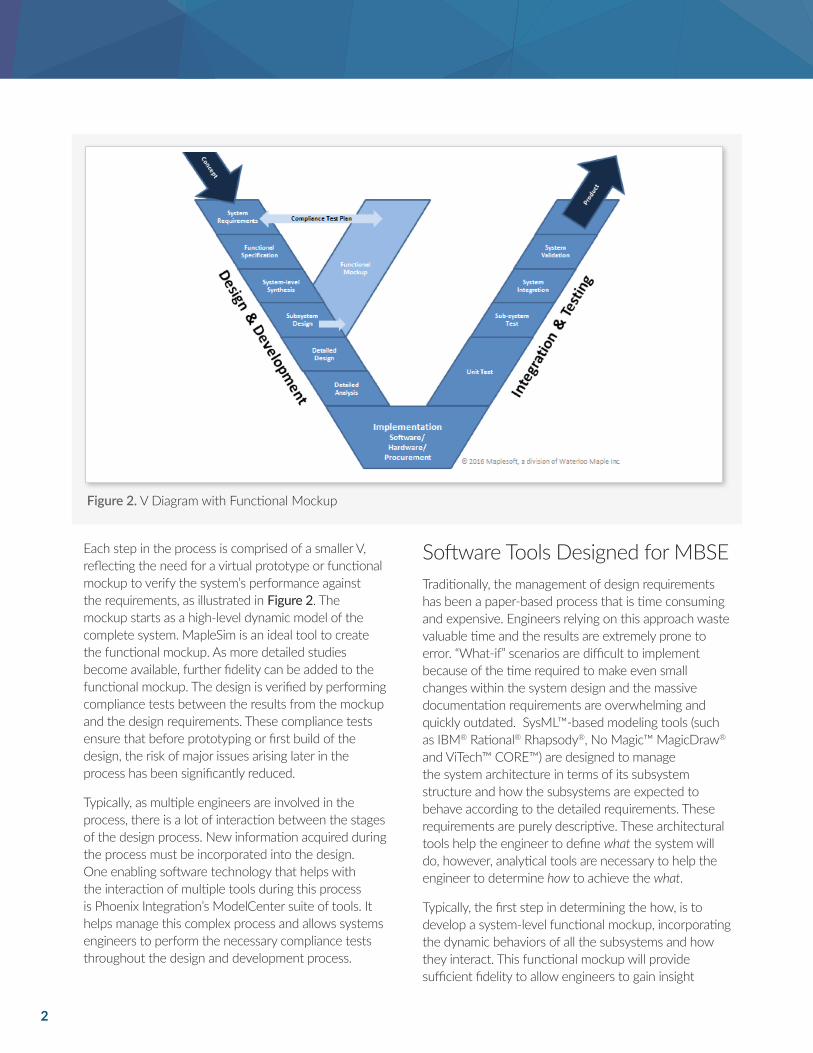
Each step in the process is comprised of a smaller V, reflecting the need for a virtual prototype or functional mockup to verify the system’s performance against the requirements, as illustrated in Figure 2. The mockup starts as a high-level dynamic model of the complete system. MapleSim is an ideal tool to create the functional mockup. As more detailed studies become available, further fidelity can be added to the functional mockup. The design is verified by performing compliance tests between the results from the mockup and the design requirements. These compliance tests ensure that before prototyping or first build of the design, the risk of major issues arising later in the process has been significantly reduced.
Typically, as multiple engineers are involved in the process, there is a lot of interaction between the stages of the design process. New information acquired during the process must be incorporated into the design. One enabling software technology that helps with the interaction of multiple tools during this process is Phoenix Integration’s ModelCenter suite of tools. It helps manage this complex process and allows systems engineers to perform the necessary compliance tests throughout the design and development process.
Software Tools Designed for MBSETraditionally, the management of design requirements has been a paper-based process that is time consuming and expensive. Engineers relying on this approach waste valuable time and the results are extremely prone to error. “What-if” scenarios are difficult to implement because of the time required to make even small changes within the system design and the massive documentation requirements are overwhelming and quickly outdated. SysML™-based modeling tools (such as IBM® Rational® Rhapsody®, No Magic™ MagicDraw®
and ViTech™ CORE™) are designed to manage the system architecture in terms of its subsystem structure and how the subsystems are expected to behave according to the detailed requirements. These requirements are purely descriptive. These architectural tools help the engineer to define what the system will do, however, analytical tools are necessary to help the engineer to determine how to achieve the what.
Typically, the first step in determining the how, is to develop a system-level functional mockup, incorporating the dynamic behaviors of all the subsystems and how they interact. This functional mockup will provide sufficient fidelity to allow engineers to gain insight
Figure 2. V Diagram with Functional Mockup
3
into how the system will behave and catch any design issues early on. MapleSim is a multidomain system-level modeling tool that is perfect for this step.
MapleSim is based on Modelica, an open, object-oriented, system-level modeling language that enables a level of understanding, power, and extensibility that is not possible with other tools. The flexible Modelica-based multidomain framework of MapleSim allows designers to incorporate components from different domains into the models and take advantage of the ever expanding library of Modelica’s highly specialized components. Models and components are open and modifiable and they are easy to reuse, extend and customize.
Models created in MapleSim can be structured to exactly reflect the system definition to provide a consistent mapping between the requirements and the physics that determine the system behavior. This structure makes it easy to perform the necessary compliance tests for the individual subsystems as well as the complete system.
The ModelCenter suite of tools brings the systems engineering modeling tools and the analytical tools together in an interactive and managed framework.
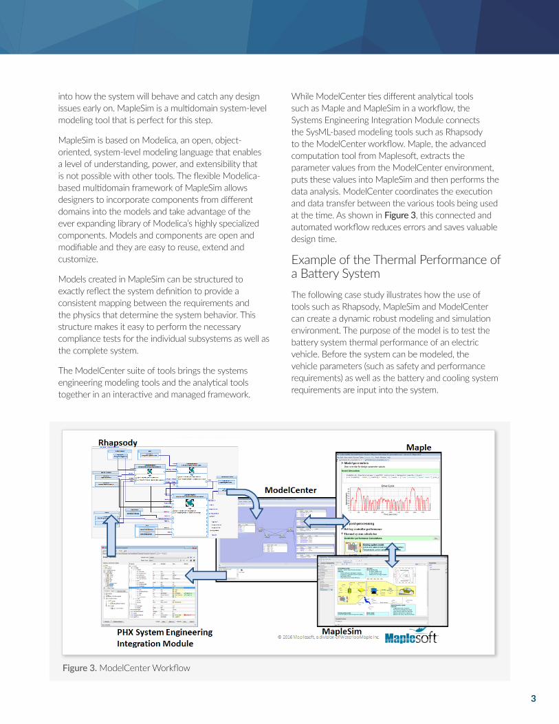
While ModelCenter ties different analytical tools such as Maple and MapleSim in a workflow, the Systems Engineering Integration Module connects the SysML-based modeling tools such as Rhapsody to the ModelCenter workflow. Maple, the advanced computation tool from Maplesoft, extracts the parameter values from the ModelCenter environment, puts these values into MapleSim and then performs the data analysis. ModelCenter coordinates the execution and data transfer between the various tools being used at the time. As shown in Figure 3, this connected and automated workflow reduces errors and saves valuable design time.
Example of the Thermal Performance of a Battery SystemThe following case study illustrates how the use of tools such as Rhapsody, MapleSim and ModelCenter can create a dynamic robust modeling and simulation environment. The purpose of the model is to test the battery system thermal performance of an electric vehicle. Before the system can be modeled, the vehicle parameters (such as safety and performance requirements) as well as the battery and cooling system requirements are input into the system.
Figure 3. ModelCenter Workflow
4
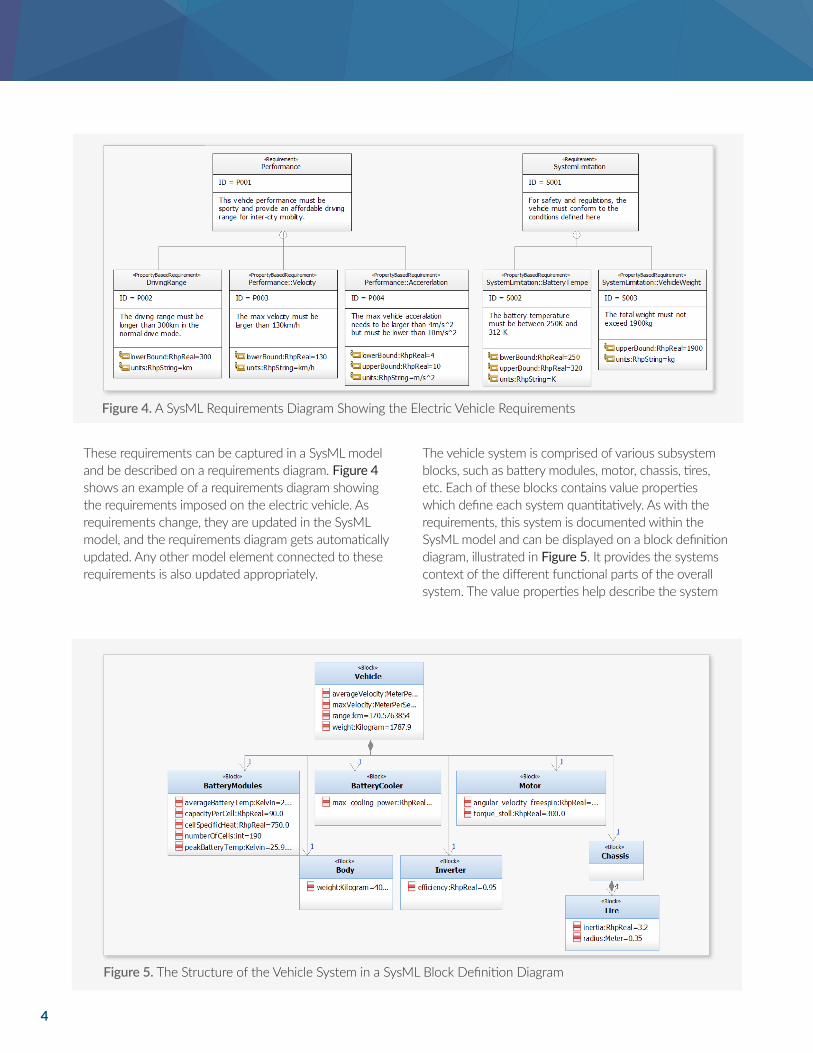
These requirements can be captured in a SysML model and be described on a requirements diagram. Figure 4 shows an example of a requirements diagram showing the requirements imposed on the electric vehicle. As requirements change, they are updated in the SysML model, and the requirements diagram gets automatically updated. Any other model element connected to these requirements is also updated appropriately.
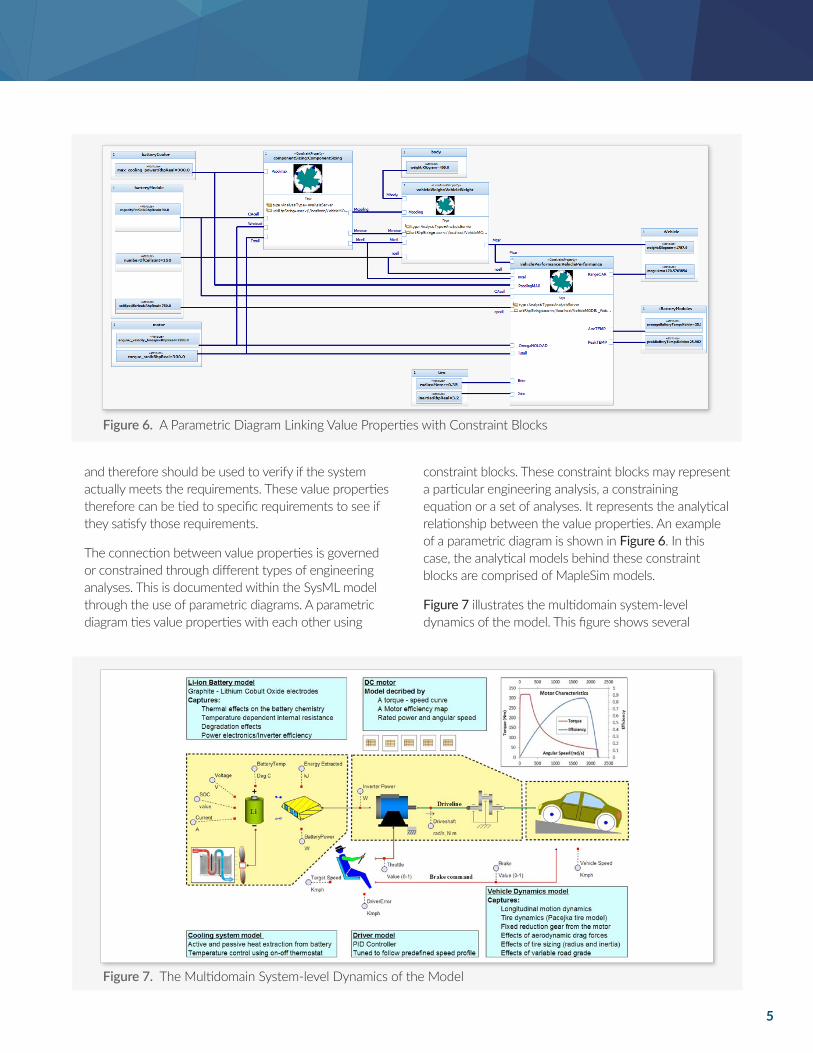
The vehicle system is comprised of various subsystem blocks, such as battery modules, motor, chassis, tires, etc. Each of these blocks contains value properties which define each system quantitatively. As with the requirements, this system is documented within the SysML model and can be displayed on a block definition diagram, illustrated in Figure 5. It provides the systems context of the different functional parts of the overall system. The value properties help describe the system
Figure 4. A SysML Requirements Diagram Showing the Electric Vehicle Requirements
Figure 5. The Structure of the Vehicle System in a SysML Block Definition Diagram
5
and therefore should be used to verify if the system actually meets the requirements. These value properties therefore can be tied to specific requirements to see if they satisfy those requirements.
The connection between value properties is governed or constrained through different types of engineering analyses. This is documented within the SysML model through the use of parametric diagrams. A parametric diagram ties value properties with each other using
constraint blocks. These constraint blocks may represent a particular engineering analysis, a constraining equation or a set of analyses. It represents the analytical relationship between the value properties. An example of a parametric diagram is shown in Figure 6. In this case, the analytical models behind these constraint blocks are comprised of MapleSim models.
Figure 7 illustrates the multidomain system-level dynamics of the model. This figure shows several
Figure 6. A Parametric Diagram Linking Value Properties with Constraint Blocks
Figure 7. The Multidomain System-level Dynamics of the Model
6
domains interacting with each other. An advantage of MapleSim is the ability to map back to the quantitative requirements to see how subsystems work together to validate the entire system. MapleSim is able to simultaneously calculate and model how variables introduced in any subsystem affect the model as a whole.
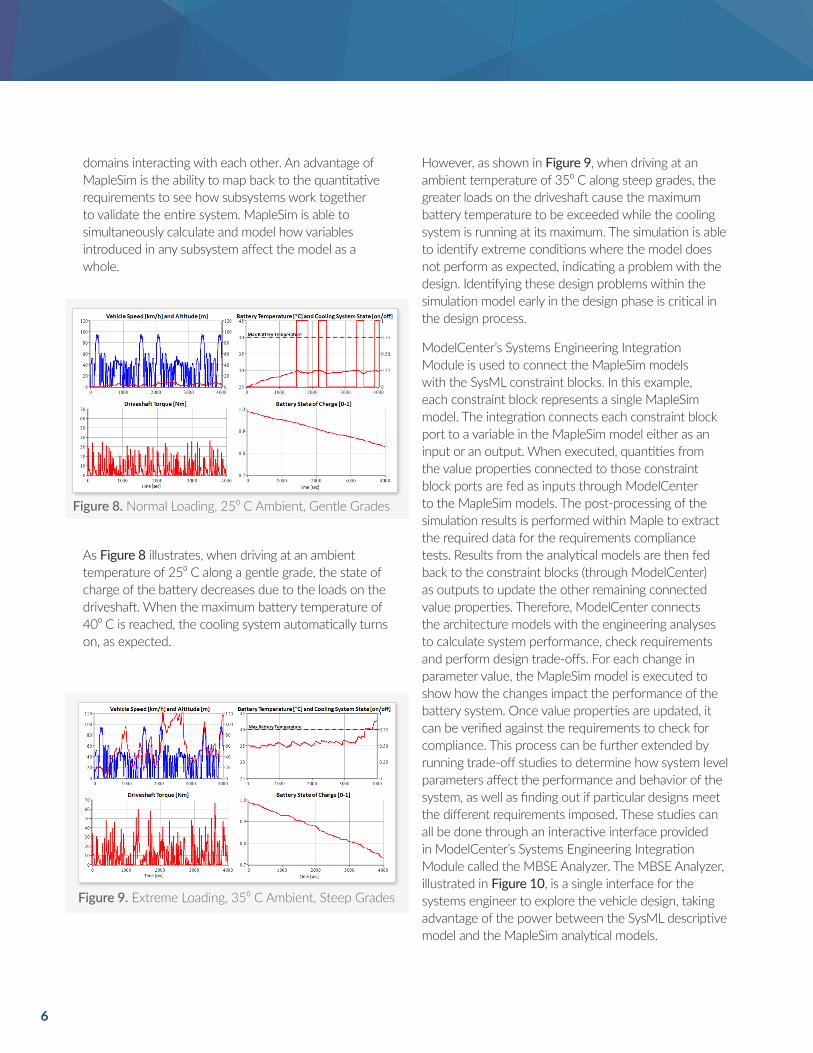
As Figure 8 illustrates, when driving at an ambient temperature of 25⁰ C along a gentle grade, the state of charge of the battery decreases due to the loads on the driveshaft. When the maximum battery temperature of 40⁰ C is reached, the cooling system automatically turns on, as expected.
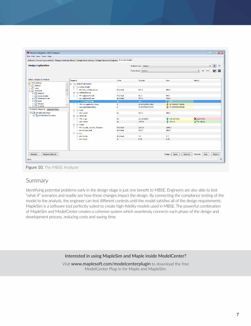
However, as shown in Figure 9, when driving at an ambient temperature of 35⁰ C along steep grades, the greater loads on the driveshaft cause the maximum battery temperature to be exceeded while the cooling system is running at its maximum. The simulation is able to identify extreme conditions where the model does not perform as expected, indicating a problem with the design. Identifying these design problems within the simulation model early in the design phase is critical in the design process.
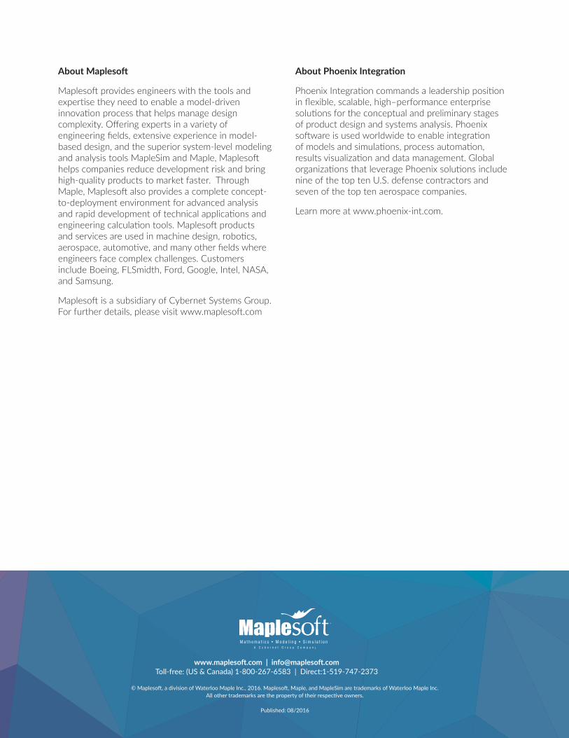
ModelCenter’s Systems Engineering Integration Module is used to connect the MapleSim models with the SysML constraint blocks. In this example, each constraint block represents a single MapleSim model. The integration connects each constraint block port to a variable in the MapleSim model either as an input or an output. When executed, quantities from the value properties connected to those constraint block ports are fed as inputs through ModelCenter to the MapleSim models. The post-processing of the simulation results is performed within Maple to extract the required data for the requirements compliance tests. Results from the analytical models are then fed back to the constraint blocks (through ModelCenter) as outputs to update the other remaining connected value properties. Therefore, ModelCenter connects the architecture models with the engineering analyses to calculate system performance, check requirements and perform design trade-offs. For each change in parameter value, the MapleSim model is executed to show how the changes impact the performance of the battery system. Once value properties are updated, it can be verified against the requirements to check for compliance. This process can be further extended by running trade-off studies to determine how system level parameters affect the performance and behavior of the system, as well as finding out if particular designs meet the different requirements imposed. These studies can all be done through an interactive interface provided in ModelCenter’s Systems Engineering Integration Module called the MBSE Analyzer. The MBSE Analyzer, illustrated in Figure 10, is a single interface for the systems engineer to explore the vehicle design, taking advantage of the power between the SysML descriptive model and the MapleSim analytical models.
Figure 8. Normal Loading, 25⁰ C Ambient, Gentle Grades
Figure 9. Extreme Loading, 35⁰ C Ambient, Steep Grades
7
SummaryIdentifying potential problems early in the design stage is just one benefit to MBSE. Engineers are also able to test “what-if” scenarios and readily see how these changes impact the design. By connecting the compliance testing of the model to the analysis, the engineer can test different controls until the model satisfies all of the design requirements. MapleSim is a software tool perfectly suited to create high-fidelity models used in MBSE. The powerful combination of MapleSim and ModelCenter creates a cohesive system which seamlessly connects each phase of the design and development process, reducing costs and saving time.
Figure 10. The MBSE Analyzer
Visit www.maplesoft.com/modelcenterplugin to download the free ModelCenter Plug-in for Maple and MapleSim.
Interested in using MapleSim and Maple inside ModelCenter?
www.maplesoft.com | [email protected] Toll-free: (US & Canada) 1-800-267-6583 | Direct:1-519-747-2373
© Maplesoft, a division of Waterloo Maple Inc., 2016. Maplesoft, Maple, and MapleSim are trademarks of Waterloo Maple Inc. All other trademarks are the property of their respective owners.
Published: 08/2016
About Maplesoft
Maplesoft provides engineers with the tools and expertise they need to enable a model-driven innovation process that helps manage design complexity. Offering experts in a variety of engineering fields, extensive experience in model-based design, and the superior system-level modeling and analysis tools MapleSim and Maple, Maplesoft helps companies reduce development risk and bring high-quality products to market faster. Through Maple, Maplesoft also provides a complete concept-to-deployment environment for advanced analysis and rapid development of technical applications and engineering calculation tools. Maplesoft products and services are used in machine design, robotics, aerospace, automotive, and many other fields where engineers face complex challenges. Customers include Boeing, FLSmidth, Ford, Google, Intel, NASA, and Samsung.
Maplesoft is a subsidiary of Cybernet Systems Group. For further details, please visit www.maplesoft.com
About Phoenix Integration
Phoenix Integration commands a leadership position in flexible, scalable, high–performance enterprise solutions for the conceptual and preliminary stages of product design and systems analysis. Phoenix software is used worldwide to enable integration of models and simulations, process automation, results visualization and data management. Global organizations that leverage Phoenix solutions include nine of the top ten U.S. defense contractors and seven of the top ten aerospace companies.
Learn more at www.phoenix-int.com.