the role of nitrogen in gun tube wear and erosion
TRANSCRIPT

The Role of Nitrogen in Gun Tube Wear and Erosion
by Paul J. Conroy, Charles S. Leveritt,
James K. Hirvonen, and John D. Demaree
ARL-TR-3795 May 2006 Approved for public release; distribution is unlimited.

NOTICES
Disclaimers The findings in this report are not to be construed as an official Department of the Army position unless so designated by other authorized documents. Citation of manufacturer’s or trade names does not constitute an official endorsement or approval of the use thereof. Destroy this report when it is no longer needed. Do not return it to the originator.
Army Research Laboratory Aberdeen Proving Ground, MD 21005-5066
ARL-TR-3795 May 2006
The Role of Nitrogen in Gun Tube Wear and Erosion
Paul J. Conroy, Charles S. Leveritt, James K. Hirvonen, and John D. Demaree
Weapons and Materials Research Directorate, ARL Approved for public release; distribution is unlimited.
ii
REPORT DOCUMENTATION PAGE Form Approved OMB No. 0704-0188
Public reporting burden for this collection of information is estimated to average 1 hour per response, including the time for reviewing instructions, searching existing data sources, gathering and maintaining the data needed, and completing and reviewing the collection information. Send comments regarding this burden estimate or any other aspect of this collection of information, including suggestions for reducing the burden, to Department of Defense, Washington Headquarters Services, Directorate for Information Operations and Reports (0704-0188), 1215 Jefferson Davis Highway, Suite 1204, Arlington, VA 22202-4302. Respondents should be aware that notwithstanding any other provision of law, no person shall be subject to any penalty for failing to comply with a collection of information if it does not display a currently valid OMB control number. PLEASE DO NOT RETURN YOUR FORM TO THE ABOVE ADDRESS. 1. REPORT DATE (DD-MM-YYYY)
May 2006 2. REPORT TYPE
Final 3. DATES COVERED (From - To)
October 2002–August 2004 5a. CONTRACT NUMBER
5b. GRANT NUMBER
4. TITLE AND SUBTITLE
The Role of Nitrogen in Gun Tube Wear and Erosion
5c. PROGRAM ELEMENT NUMBER
5d. PROJECT NUMBER
AH80 5e. TASK NUMBER
6. AUTHOR(S)
Paul J. Conroy, Charles S. Leveritt, James K. Hirvonen, and John D. Demaree
5f. WORK UNIT NUMBER
7. PERFORMING ORGANIZATION NAME(S) AND ADDRESS(ES)
US Army Research Laboratory ATTN: AMSRD-ARL-WM-BD Aberdeen Proving Ground, MD 21005-5066
8. PERFORMING ORGANIZATION REPORT NUMBER
ARL-TR-3795
10. SPONSOR/MONITOR'S ACRONYM(S)
9. SPONSORING/MONITORING AGENCY NAME(S) AND ADDRESS(ES)
11. SPONSOR/MONITOR'S REPORT NUMBER(S)
12. DISTRIBUTION/AVAILABILITY STATEMENT
Approved for public release; distribution is unlimited.
13. SUPPLEMENTARY NOTES
14. ABSTRACT
The U.S. Army Research Laboratory has recently made discoveries in the area of interior ballistic propellant combustion product interactions with a gun-tube bore. These discoveries were based on two hypotheses. The first was that the products could and are “dynamically” nitriding the bore of the gun, thus creating a nitride coating which inhibits the dissociation of CO and subsequently reduces the amount of carbon uptake. The second was that the combustion products richer in nitrogen have a lower temperature upon expansion in our experimental fixture as well as in a gun barrel. This is due to Joule and/or Joule-Thomson cooling effects. Both of these hypotheses were proven and validated through numerical and experimental methods. Higher nitrogen containing combustion products have definitively been shown to have relatively lower erosivity with respect to those having lower nitrogen content. These results have revolutionized the gun propellant development community in that for the first time, there is guidance for erosivity control through propellant chemical constituent formulation.
15. SUBJECT TERMS
gun tube erosion, surface chemistry, high nitrogen, novel propellant
16. SECURITY CLASSIFICATION OF: 19a. NAME OF RESPONSIBLE PERSON Paul Conroy
a. REPORT UNCLASSIFIED
b. ABSTRACT UNCLASSIFIED
c. THIS PAGE UNCLASSIFIED
17. LIMITATION OF ABSTRACT
UL
18. NUMBER OF PAGES
28 19b. TELEPHONE NUMBER (Include area code)
410-278-6114 Standard Form 298 (Rev. 8/98) Prescribed by ANSI Std. Z39.18

iii
Contents
List of Figures iv
List of Tables iv
1. Introduction 1
2. Discovery of Dynamic Nitriding 1
3. Temperature Reduction Due to Expansion 6 3.1 Isenthalpic Expansion......................................................................................................8
3.2 Free Expansion ................................................................................................................9
4. Prenitriding 10
5. Conclusions 12
6. References 13
List of Symbols, Abbreviations, and Acronyms 15
Distribution List 16
iv
List of Figures
Figure 1. Photograph of an ARL 37-mm erosion fixture................................................................2 Figure 2. Drawing of an ARL 37-mm erosion fixture. ...................................................................2 Figure 3. ARL erosion fixture nozzle. ............................................................................................3 Figure 4. ARL ion accelerator facility. ...........................................................................................4 Figure 5. Nuclear reaction analysis (NRA) chamber......................................................................5 Figure 6. Depth profiles of nitrogen taken using NRA at four different positions
relative to the inner exposed surface of the test nozzle. ............................................................5 Figure 7. Iron/carbon phase diagram (Metals Handbook, 1973). ...................................................7 Figure 8. Iron/nitrogen phase diagram (Guillermet and Du, 1994). ...............................................7 Figure 9. Traditional and preferred nitrogen profiles. ..................................................................11
List of Tables
Table 1. Selected propellant properties and mass loss....................................................................3 Table 2. Van der Waals constants comparisons of products. .........................................................9
1
1. Introduction
Gun tube wear and erosion has been a limiting factor in gun performance since their invention. Frederick Abel described gun tube erosion in the nineteenth century when he developed cordite. Since that time, erosion has had a cyclic history between performance requirements, resulting erosion issues, and subsequent palliatives. Historically, palliatives have been additives to the propelling charge to create a protective surface coating, a cool boundary layer, or a heat flux impediment. To date, this is the preferred method of mitigating erosion given an existing weapon-charge system.
For over 10 years, the U.S. Army Research Laboratory (ARL) has been performing basic research in the area of gun tube wear and erosion, after a hiatus of about 10 years from the early 1980s through the early 1990s. Propellant chemistry and the interaction of the combustion products with the gun-tube wall has been the primary driver of the research. Since WWII, it has been noted (Smith, 1954) that propellants containing nitramine are inherently more erosive than conventional propellants such as M30 (a triple-based propellant having a similar adiabatic flame temperature). This claim was later verified by Ward et al. (1981, 1982). The reason for the high erosive behavior of this propellant was unknown. Surface chemical analysis of gun surfaces by Benet Laboratory (Kamdar and Venables, 1984) and ARL modeling (Conroy et al., 2001) assisted in developing an explanation for this behavior.
The primary finding of this previous work was that the carbon monoxide in the combustion product gas dissociated on the surface with a very small energy barrier. Subsequently, the free hydrogen scavenged the oxygen from the surface into water and the carbon diffused into the steel surface, resulting in a surface carburization (Conroy et al., 2001). This transforms the steel into a cast iron, which reduces the surface melt temperature from 1723 K down to 1423 K. RDX-based propellants have significantly higher amounts of carbon monoxide than the triple-base propellant M30, which supports the hypothesis of CO dissociation and subsequent carburization.
The current report describes work involving advanced propellant formulations having relatively high concentrations of nitrogen in the product species.
2. Discovery of Dynamic Nitriding
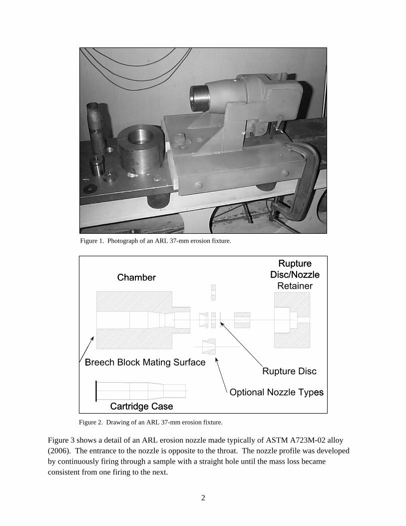
Propellant erosivity characterizations were conducted in a blowout chamber fabricated from the breech and chamber of a 37-mm gun shortened and threaded to accept a retaining end cap for experimental samples. A photograph is shown in figure 1 and sectional drawing is shown in figure 2. This facility in various forms has been in use since WWII (Weigand, 1945).
2
Figure 1. Photograph of an ARL 37-mm erosion fixture.
Figure 2. Drawing of an ARL 37-mm erosion fixture.
Figure 3 shows a detail of an ARL erosion nozzle made typically of ASTM A723M-02 alloy (2006). The entrance to the nozzle is opposite to the throat. The nozzle profile was developed by continuously firing through a sample with a straight hole until the mass loss became consistent from one firing to the next.
Cartridge Case
ChamberRupture
Disc/Nozzle Retainer
Rupture Disc
Optional Nozzle Types
Breech Block Mating Surface
Cartridge Case
ChamberRupture
Disc/Nozzle Retainer
Rupture Disc
Optional Nozzle Types
Breech Block Mating Surface
3
Figure 3. ARL erosion fixture nozzle.
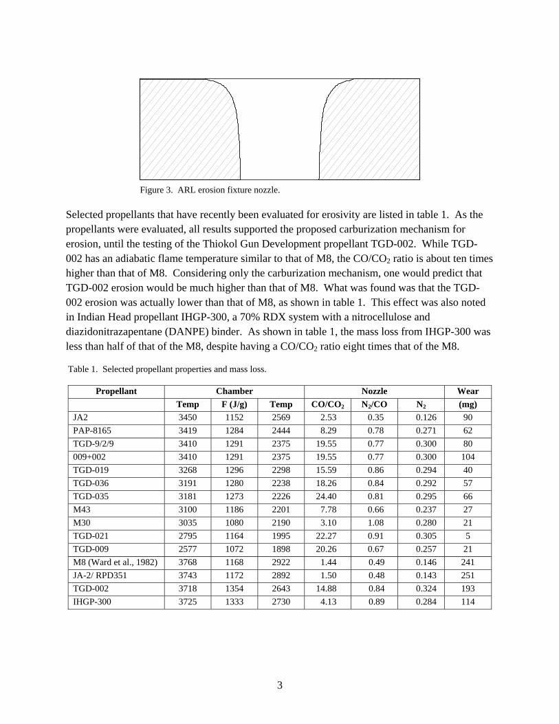
Selected propellants that have recently been evaluated for erosivity are listed in table 1. As the propellants were evaluated, all results supported the proposed carburization mechanism for erosion, until the testing of the Thiokol Gun Development propellant TGD-002. While TGD-002 has an adiabatic flame temperature similar to that of M8, the CO/CO2 ratio is about ten times higher than that of M8. Considering only the carburization mechanism, one would predict that TGD-002 erosion would be much higher than that of M8. What was found was that the TGD-002 erosion was actually lower than that of M8, as shown in table 1. This effect was also noted in Indian Head propellant IHGP-300, a 70% RDX system with a nitrocellulose and diazidonitrazapentane (DANPE) binder. As shown in table 1, the mass loss from IHGP-300 was less than half of that of the M8, despite having a CO/CO2 ratio eight times that of the M8.
Table 1. Selected propellant properties and mass loss.
Propellant Chamber Nozzle Wear Temp F (J/g) Temp CO/CO2 N2/CO N2 (mg) JA2 3450 1152 2569 2.53 0.35 0.126 90 PAP-8165 3419 1284 2444 8.29 0.78 0.271 62 TGD-9/2/9 3410 1291 2375 19.55 0.77 0.300 80 009+002 3410 1291 2375 19.55 0.77 0.300 104 TGD-019 3268 1296 2298 15.59 0.86 0.294 40 TGD-036 3191 1280 2238 18.26 0.84 0.292 57 TGD-035 3181 1273 2226 24.40 0.81 0.295 66 M43 3100 1186 2201 7.78 0.66 0.237 27 M30 3035 1080 2190 3.10 1.08 0.280 21 TGD-021 2795 1164 1995 22.27 0.91 0.305 5 TGD-009 2577 1072 1898 20.26 0.67 0.257 21 M8 (Ward et al., 1982) ( d )
3768 1168 2922 1.44 0.49 0.146 241 JA-2/ RPD351 3743 1172 2892 1.50 0.48 0.143 251 TGD-002 3718 1354 2643 14.88 0.84 0.324 193 IHGP-300 3725 1333 2730 4.13 0.89 0.284 114

4
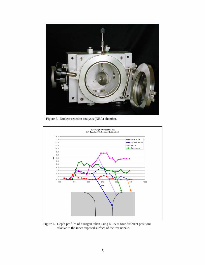
It was hypothesized that high nitrogen propellants might “dynamically” nitride the inside bore surface of the erosion nozzle during firing. This nitriding could occur over milliseconds, whereas typical gaseous nitriding can take hours or days. We investigated this possibility by measuring the nitrogen content on the surface of test nozzles after firing, using resonant nuclear reaction analysis at the ARL ion accelerator facility shown in figure 4. An energetic beam of protons was directed onto the surface, inducing the 15N(p,γ) reaction, and the characteristic gamma rays were detected using a scintillation detector near the analysis chamber (figure 5). Since this reaction occurs only at a particular ion energy, the beam energy was increased to query the nitrogen concentration at increasing depths into the sample; the gamma yield could then be calibrated to give a depth profile of nitrogen in the gun steel. Figure 6 shows atomic nitrogen content vs. energy (depth) at various locations on the inner surface of an ARL erosion nozzle, which had high nitrogen propellant products exhausted through it. The resultant concentrations are as high as 9 atomic percent. This places the nitriding at Fe4N levels.
Figure 4. ARL ion accelerator facility.
5
Figure 5. Nuclear reaction analysis (NRA) chamber.
Figure 6. Depth profiles of nitrogen taken using NRA at four different positions relative to the inner exposed surface of the test nozzle.
Gun Sample TGD-021 Flat Side(100 Counts of Background Subtraction)
0.0
1.0
2.0
3.0
4.0
5.0
6.0
7.0
8.0
9.0
10.0
11.0
12.0
13.0
14.0
880 900 920 940 960 980 1000
keV
%N
Middle of Flat
Flat Near Nozzle
Nozzle
Back Nozzle

6
Possible explanations for how surface nitriding can assist in erosion reduction come from surface chemistry, as well as from the binary phase diagram of iron nitride.
Literature suggests that nitrogen on a steel surface may inhibit dissociation of CO (Ponec and van Barneveld, 1979). Thus, dynamic nitriding can act to interrupt the primary driving reaction of the chemical erosion mechanism, which is the adsorption/dissociation of carbon monoxide on the surface. Also, the presence of nitrogen takes up sites in solution with iron and could inhibit the subsurface diffusion of the free carbon into the steel.
Carburization of the gun reduces the melt temperature of the surface from 1723 K to 1423 K. The binary iron-carbon phase diagram in figure 7 shows how this reduction in melt temperature occurs. The virgin 4340 or ASTM A723M-02 (2006) steel begins with about 0.4% carbon. As carbon is added to this mixture, the melt temperature continuously reduces until it stabilizes at 1423 K, which defines the boundary between cast iron and steel. Once the carbon concentration exceeds 2.1%, the material is then cast iron. Erosion calculations have shown that the surface can saturate with carbon providing the best boundary source available for diffusion (Conroy et al., 2001). This enables the formation of substrate iron carbide at the maximum rate possible. As the ballistic cycle progresses the surface temperature rises, all the while carbon is diffusing and creating Fe3C. Once the surface temperature reaches 1423 K, the energy balance on the surface including phase transformation results in macroscopic melting. This is one of the primary mechanisms for the removal of surface and interfacial material (Conroy et al., 2001).
The iron/nitrogen phase diagram presented in figure 8 (Guillermet and Du, 1994) demonstrates how nitrogen in solution with iron can be more resistant to erosion than carbon in solution with iron under ballistic conditions. The phase transition from solid to liquid for iron nitride is shown as a constant 1683 K, between 7 and 20 atomic percent nitrogen. This presents a remarkable 260 K increase in the surface melt temperature over that of the iron carbide at 1423 K. For chrome plated tubes, this increase is obtained at the weakest point of the system, which is at the interface between the chrome and steel at the bottom of cracks in the chrome coating (Conroy et al., 2001). This represents an enormous opportunity for improvement for gun systems in terms of tube life and possibly system performance.
3. Temperature Reduction Due to Expansion
In addition to the dynamic nitriding, nitrogen can also reduce the product gas temperature in regions of expansion due to higher intermolecular attraction forces and larger product molecular size through the Joule and Joule-Thomson effects.

7
Figure 7. Iron/carbon phase diagram (Metals Handbook, 1973).
Nitrogen Concentration CN [ at. %]
0 5 10 15 20 25 30 35 40 45 50 55 60
Tem
pera
ture
(K)
400
600
800
1000
1200
1400
1600
1800
2000
Liquid
Fe4N FeNFe2NFe
?''γ
-Fe2N
γ
-FeN -FeN'''γ''γ
-Fe(N) -Fe2+zNε
-Fe16N2"α
'α -Fe(N)α-Fe -Fe(N)
8.8
19.315.910.30.4
Fe3C Melt
Fe4N Melt
260K!
Liquid
Figure 8. Iron/nitrogen phase diagram (Guillermet and Du, 1994).
IRON CARBON EQUILIBRIUM DIAGRAM
Carbon (weight %)
0.5 1.5 2.5 3.5 4.50.0 1.0 2.0 3.0 4.0 5.0
Tem
pera
ture
(F)
1000
1400
1800
2200
2600
1200
1600
2000
2400
2800
Tem
pera
ture
(K)
900
1100
1300
1500
1700
1900
800
1000
1200
1400
1600
1800
Austenite + Fe3C
Iron Fe3C Equilibrium-
Iron Graphite Equilibrium-
Source: Based on Metals Handbook 8thEdition. Vol 8 "metallography Structuresand Phase Diagrams" (after John Chipman)
Ferrite + Austenite
Austenite(Gamma Iron)
Solidus
Liquid + Austenite
2.08%
2.11%
0.53%Delta Iron
Liquid + Delta Iron
1811
0.17%
Delta Iron + Austenite
1667
1768
Mushy State
Liquid
LiquidusLiquid + Graphite
Fe3CLiquidus(calculated)
1421
1427
4.26%
4.36% Liquid + Fe3C
0.68%
0.77%
Curie Temp 1043Ferrite
0.0218%
1011
1000
1185
0.096%
4340
Steel Cast Iron
8
Two processes have been considered for their effect on temperature reduction: isenthalpic expansion (throttling) and free expansion of gases (Sears and Salinger, 1975; Van Wylen and Sonntag, 1985). These processes relate in some respects to the expanding gases found in a gun during the interior ballistic cycle. The following analysis is an attempt to physically describe why the gases cool upon expansion as well as the effect that mixture composition might have upon the expanding combustion products.
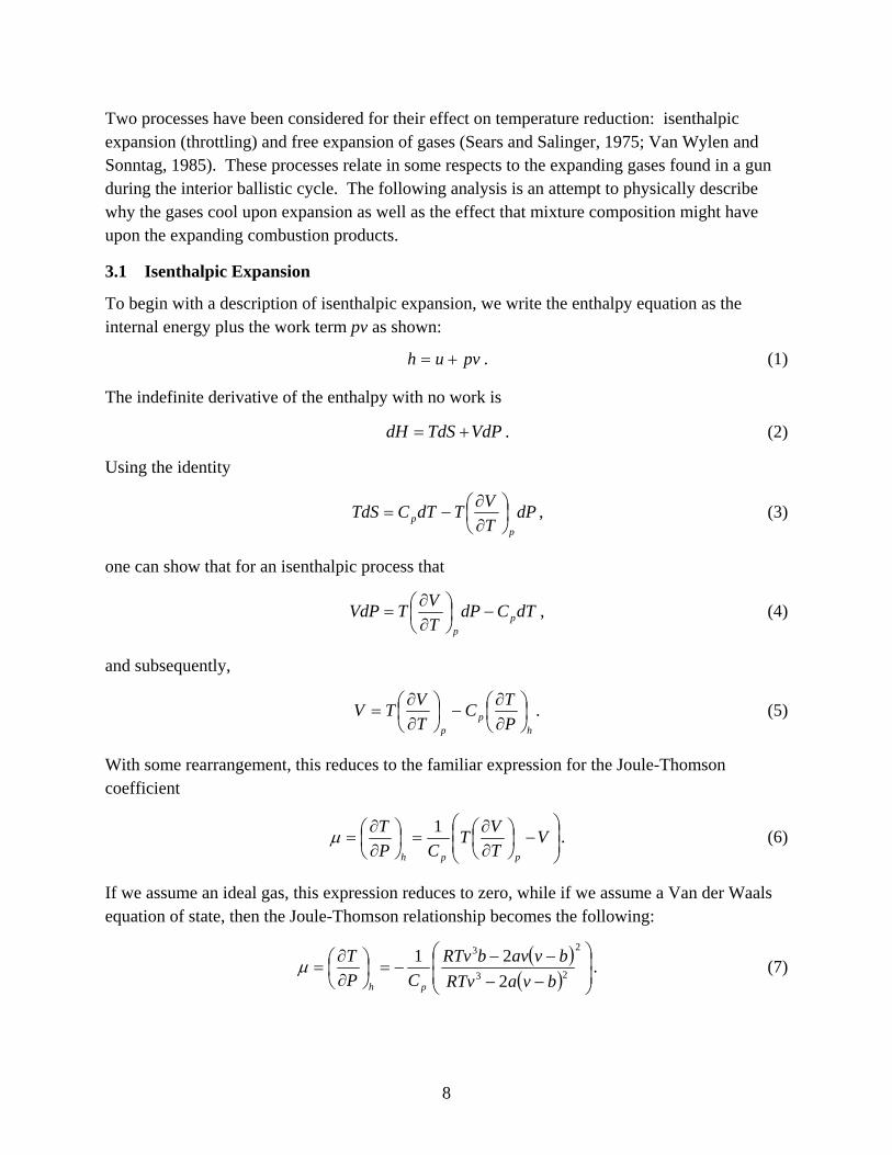
3.1 Isenthalpic Expansion
To begin with a description of isenthalpic expansion, we write the enthalpy equation as the internal energy plus the work term pv as shown:
pvuh += . (1)
The indefinite derivative of the enthalpy with no work is
VdPTdSdH += . (2)
Using the identity
dPTVTdTCTdS
pp ⎟
⎠⎞
⎜⎝⎛∂∂
−= , (3)
one can show that for an isenthalpic process that
dTCdPTVTVdP p
p
−⎟⎠⎞
⎜⎝⎛∂∂
= , (4)
and subsequently,
h
pp P
TCTVTV ⎟
⎠⎞
⎜⎝⎛∂∂
−⎟⎠⎞
⎜⎝⎛∂∂
= . (5)
With some rearrangement, this reduces to the familiar expression for the Joule-Thomson coefficient
⎟⎟⎠
⎞⎜⎜⎝
⎛−⎟
⎠⎞
⎜⎝⎛∂∂
=⎟⎠⎞
⎜⎝⎛∂∂
= VTVT
CPT
pph
1µ . (6)
If we assume an ideal gas, this expression reduces to zero, while if we assume a Van der Waals equation of state, then the Joule-Thomson relationship becomes the following:
( )( ) ⎟
⎟⎠
⎞⎜⎜⎝
⎛
−−−−
−=⎟⎠⎞
⎜⎝⎛∂∂
=2
23
3
221
bvaRTvbvavbRTv
CPT
ph
µ . (7)

9
When µ is equal to zero in this relationship the function defines the temperature inversion curve, which is the limit at which a specific species will cool if expanded when initially below the inversion temperature and heat if expanded above the inversion temperature. The relationship of the inversion temperature is
2
2)(2
bRvbvaTi
−= . (8)
From table 2, the inversion temperature shows that reducing or replacing the hydrogen with nitrogen would be beneficial from a temperature reduction point of view during an isenthalpic process.
Table 2. Van der Waals constants comparisons of products.
Product Species Van der Waals Constant a (Intermolecular Attractive
Force Constant) (kJm3/kmole)
Van der Waals Constant b (Molecular size constant)
(m3/kmole)
Inversion
Temperature (K) (@ v = 0.4m3/kg)
H2 25 0.0266 1000. N2 137 0.0387 7803 CO 148 0.0395 8610 CO2 365 0.0428 23032 H2O 553 0.0305 24656
Unfortunately, there will be a penalty in performance for such a propellant, because the impetus will suffer as the average molecular weight of the products is increased as equation 9 shows:
RTImpetusMW
= . (9)
3.2 Free Expansion
Of course, what happens in a real gun is expansion with work. An adiabatic system with no work undergoing free expansion might be more representative of what occurs before the throat of a nozzle. In this case the internal energy is constant and the change in volume is accompanied by a change in temperature. Differentiating the internal energy with the aforementioned constraints, as well as constant mass, results in
dVVUdT
TUdU
NTNV ,,⎟⎠⎞
⎜⎝⎛∂∂
+⎟⎠⎞
⎜⎝⎛∂∂
= . (10)
From this, we note that the change in internal energy is zero so that
dVVTdV
VU
CdV
TUVU
dTNUNTV
NV
NT
,,
,
, 1⎟⎠⎞
⎜⎝⎛∂∂
=⎟⎠⎞
⎜⎝⎛∂∂
−=⎟⎠⎞
⎜⎝⎛∂∂
⎟⎠⎞
⎜⎝⎛∂∂
−= , (11)
10
which is the differential Joule coefficient. If we assume an ideal equation of state, this term becomes zero and the effect is lost. However, if we assume the Van der Waals equation of state
( ) nRTnbVVanP =−⎟⎟
⎠
⎞⎜⎜⎝
⎛+ 2
2
, (12)
then through the following identity computed through differentiation of the first and second laws
PTPT
VU
VT
−⎟⎠⎞
⎜⎝⎛∂∂
=⎟⎠⎞
⎜⎝⎛∂∂ , (13)
the following relationship can be derived describing the change in internal energy with respect to volume:
2
2
Van
VU
T
=⎟⎠⎞
⎜⎝⎛∂∂ . (14)
This implies that the larger the intermolecular attractive force the larger the temperature decrease will be. Therefore, from table 1, the more hydrogen that can be replaced by nitrogen in the combustion products the lower the temperature will be in the entrance region of the nozzle. This once again implies a negative impact upon the impetus of the propellant, as equation 9 shows.
A general conclusion is that a reduction in expansion temperature due to the replacement of hydrogen with nitrogen in the products will be accompanied by a reduction in impetus for a gun propellant. While the erosion might be reduced through the Joule and/or Joule-Thomson effects, the impetus of the propellant will decrease through the overall increase in average molecular weight. Thus, there is an apparent balance between erosion and performance. However, it may be possible to increase the loading density through advanced charge designs to overcompensate for the reduced impetus, which would result in an overall performance increase while reducing/ minimizing the erosion.
4. Prenitriding
The discovery of dynamic nitriding leads to an exciting corollary: prenitriding a gun tube could provide significant benefits. Nitriding has been performed for over half a century on gun tubes (Di Pietro, 1947). The M242 Bushmaster cannon has specifications stating that the bore can be either chrome plated or nitrided. Current nitriding results in a very reproducible wear and barrel life in comparison to chrome plating, which is sometimes less reproducible (Waterfield, 2003). Unfortunately, nitrided M242 barrels do not have the erosion life of the chrome barrels. We may now be able to explain this result.
11
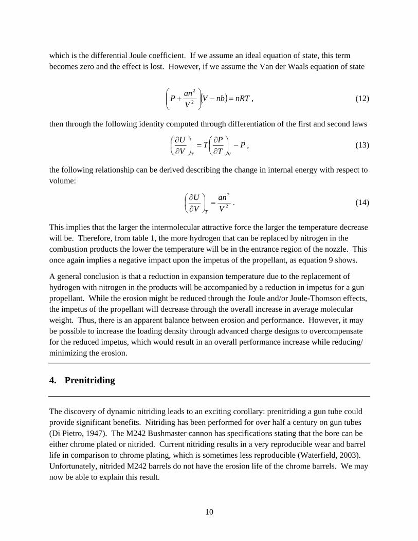
Conventional nitriding produces an error function distribution of nitrogen in the surface. This distribution ranges from a hard white layer (FeN) on the surface, through all the substoichiometric nitrides of iron, to deep into the iron where there is no nitrogen present. This implies a melting temperature range from as low as 1200 K at the surface up to the optimal temperature of 1683 K where the nitrogen content ranges from 7–20 atomic percent (figure 8). Unfortunately, by the time the erosion progresses until the surface has an optimal melt temperature there is not much nitrogen left, as shown in figure 9 in the traditional nitride profile.
Figure 9. Traditional and preferred nitrogen profiles.
Conversely, if the nitrogen profile appears as in the desired nitrogen profile of figure 9, then the benefit is realized throughout the life of the gun tube. This profile may be reached through laser nitriding (Schaaf, 2002).
The benefit could also be realized if the surface of chromed or otherwise coated tubes were pre-nitrided to protect the interface between the coating and substrate steel from degradation when cracks occur.
Depth Into Surface
0.0 0.1 0.2 0.3 0.4 0.5 0.6 0.7 0.8 0.9 1.0
Nitr
ogen
(Ato
mic
Per
cent
)
0
10
20
30
40
50
60
Fe4N
FeN
Fe2N
Traditional Nitrogen
Concentration Profile
Desired Nitrogen Concentration Profile
12
5. Conclusions
The dynamic nitriding and the temperature reduction due to propellant gas expansion have been shown to lead to remarkably reduced erosion resulting from propellant formulations having relatively high nitrogen content.
The new energetic propellant formulations that include “high nitrogen” ingredients can lead to reduced gun barrel erosion for both legacy systems and future armaments. This discovery is applicable to every gun system in the Department of Defense inventory, including mortars. Furthermore, for the first time propellant formulators have the ability and guidance to produce inherently less erosive propellants through energetic ingredient selection.
13
6. References
ASTM A723M-02. Standard Specification for Alloy Steel Forgings for High-Strength Pressure Component Application. Annu. Book ASTM Stand. 2006, Vol 01.95.
Conroy, P. J.; Weinacht, P.; Nusca, M. J. Gun Tube Coatings in Distress; ARL-TR-2393; U.S. Army Research Laboratory: Aberdeen Proving Ground, MD, February 2001.
Di Pietro, W. Nitriding by Glow Discharge. WAL-634/4, 1947 (AD-a953 186).
Guillermet A. F.; Du, H. Z. Thermodynamic Analysis of the Fe-N System Using the Compound –Energy Model with Predictions of the Vibrational Energy. Metallkunde 1994, 85, 154–163.
Kamdar, M. H.; Venables, J. D. Characterization of Surface Layers in Gun Barrels; ARLCB-TR-84041; U.S. Army Armament Research and Development Center: Watervliet, NY, 1984.
Metals Handbook. Vol. 8, 8th ed.; Metallography, Structures and Phase Diagrams, ASM: Materials Park, OH, 1973.
Ponec, V.; van Barneveld, W. A. The Role of Chemisorption in Fischer-Tropsch Synthesis. Journal of Industrial Engineering Chemical Product Research and Development 1979, 18 (4).
Schaaf, P. Laser Nitriding of Metals. Progress in Materials Science 2002, 47, 1–161.
Sears, F. W.; Salinger, G. L. Thermodynamics, Kinetic Theory, and Statistical Thermodynamics. Addison Wesley: Boston, MA, 1975.
Smith, N. H. Comparison of the Erosiveness of Propellant Powders; NDRC Armor and Ordnance Report A-451; National Defense Research Council: Washington, DC, October 1954.
Van Wylen, G. J.; Sonntag, R. E. Fundamentals of Classical Thermodynamics; Wiley: Hoboken, NJ, 1985.
Ward, J. R.; Brosseau, T. L.; Kaste, R. P.; Stobie, I. C.; Bensinger, B. Erosivity of LOVA Propellants; BRL-TR-02368; U.S. Army Ballistics Research Laboratory: Aberdeen Proving Ground, MD, September 1981.
Ward, J. R.; Kaste, R. P.; Stobie, I. C.; Bensinger, B. D. Role of Surface Oxide on Gun Barrel Wear; BRL-TR-02437; U.S. Army Ballistics Research Laboratory: Aberdeen Proving Ground, MD, November 1982.

14
Waterfield, R. W. ATK Ordnance and Ground Systems, Mesa, AZ. Private communication, 2003.
Weigand, L. The Application of Erosion in Vent Plugs to Recoilless Guns; BRL-MR-340; U.S. Army Ballistics Research Laboratory: Aberdeen Proving Ground, MD, 21005, January 1945.
15
List of Symbols, Abbreviations, and Acronyms
a Van der Waals intermolecular force constant
b Van der Waals molecular volume constant
Cp specific heat at constant pressure
h specific enthalpy
MW molecular weight
P pressure
R ideal gas constant
S entropy
T temperature
u specific internal energy
V volume
ν specific volume
µ Joule Thomson coefficient
NO. OF COPIES ORGANIZATION
16
1 DEFENSE TECHNICAL (PDF INFORMATION CTR ONLY) DTIC OCA 8725 JOHN J KINGMAN RD STE 0944 FORT BELVOIR VA 22060-6218 1 US ARMY RSRCH DEV & ENGRG CMD SYSTEMS OF SYSTEMS INTEGRATION AMSRD SS T 6000 6TH ST STE 100 FORT BELVOIR VA 22060-5608 1 INST FOR ADVNCD TCHNLGY THE UNIV OF TEXAS AT AUSTIN 3925 W BRAKER LN AUSTIN TX 78759-5316 1 DIRECTOR US ARMY RESEARCH LAB IMNE ALC IMS 2800 POWDER MILL RD ADELPHI MD 20783-1197 3 DIRECTOR US ARMY RESEARCH LAB AMSRD ARL CI OK TL 2800 POWDER MILL RD ADELPHI MD 20783-1197
ABERDEEN PROVING GROUND 1 DIR USARL AMSRD ARL CI OK TP (BLDG 4600)
NO. OF NO. OF COPIES ORGANIZATION COPIES ORGANIZATION
17
1 HQDA DAMO FDT 400 ARMY PENTAGON WASHINGTON DC 20310-6218 1 DARPA SPECIAL PROJECTS OFFICE J CARLINI 3701 N FAIRFAX DR ARLINGTON VA 22203-1714 1 DIRECTOR US ARMY RESEARCH LAB AMSRD ARL D J MILLER 2800 POWDER MILL RD ADELPHI MD 20783-1197 1 HQDA DIR R&D SAAL TR W MORRISON SUITE 9800 2511 JEFFERSON DAVIS HWY ARLINGTON VA 22201 1 HQ US ARMY MATERIEL CMD 9301 CHAPEK ROAD FORT BELVOIR VA 22060-5527 1 US ARMY BMDS CMD ADVANCED TECHLGY CTR PO BOX 1500 HUNTSVILLE AL 35807-3801 1 OFC OF THE PRODUCT MGR SFAE AR HIP IP R DE KLEINE PICATINNY ARSENAL NJ 07806-5000 1 CDR US ARMY ARDEC PROD BASE MODRNZTN AGENCY AMSMC PBM A SIKLOSI PICATINNY ARSENAL NJ 07806-5000 1 CDR US ARMY ARDEC PROD BASE MODRNZTN AGENCY AMSTA AR WES L LAIBSON PICATINNY ARSENAL NJ 07806-5000
4 PM PEO ARMAMENTS TANK MAIN ARMAMENT SYS AMCPM TMA AMCPM TMA 105 AMCPM TMA AS H YUEN PICATINNY ARSENAL NJ 07806-5000 2 CDR US ARMY ARDEC AMSTA AR CCH B C MANDALA E FENNELL PICATINNY ARSENAL NJ 07806-5000 1 CDR US ARMY ARDEC AMSTA AR CCS PICATINNY ARSENAL NJ 07806-5000 1 CDR US ARMY ARDEC AMSTA AR WE PICATINNY ARSENAL NJ 07806-5000 2 PM MAS SFAE AMO MAS SMC PICATINNY ARSENAL NJ 07806-5000 1 COMMANDER US ARMY ARDEC AMSTA AR CCH P J LUTZ PICATINNY ARSENAL NJ 07806-5000 3 CDR US ARMY ARDEC ST A AR AEE WW M MEZGER D WIEGAND P LU PICATINNY ARSENAL NJ 07806-5000 1 CDR US ARMY ARDEC AMSTA AR DB ST G FERDINAND PICATINNY ARSENAL NJ 07806-5000

NO. OF NO. OF COPIES ORGANIZATION COPIES ORGANIZATION
18
9 CDR US ARMY ARDEC AMSTA AR WEE S EINSTEIN S WESTLEY S BERNSTEIN J RUTKOWSKI B BRODMAN P OREILLY R CIRINOONE P HUI J OREILLY PICATINNY ARSENAL NJ 07806-5000 1 CDR AMSTA AR FS T GORA PICATINNY ARSENAL NJ 07806-5000 1 CDR US ARMY ARDEC AMSTA AR FS DH PICATINNY ARSENAL NJ 07806-5000 2 CDR US ARMY ARDEC AMSTA AR FS AS R KOPMANN B MACHAK PICATINNY ARSENAL NJ 07806-5000 1 CDR US ARMY ARDEC AMST A AR FSA D K CHUNG PICATINNY ARSENAL NJ 07806-5000 1 DIR BENET WEAPONS LAB AMSTA AR CCB T S SOPOK WATERVLIET NY 12189-4050 1 DIR BENET WEAPONS LAB AMSTA AR CCB TA M AUDINO WATERVLIET NY 12189-4050 1 DIR BENET WEAPONS LAB AMSTA AR CCB D R HASENBEIN WATERVLIET NY 12189-4050
2 CDR US ARMY RSRCH OFC TECH LIB D MANN PO BOX 12211 RESEARCH TRIANGLE PARK NC 27709-2211 1 PM US ARMY TANK AUTOMOTIVE CMD AMCPM ABMS T DEAN WARREN MI 48092-2498 1 PM US ARMY TANK AUTOMOTIVE CMD FIGHTING VEHICLES SYSTEMS SFAE ASM BV WARREN MI 48397-5000 1 PM US ARMY TANK AUTOMOTIVE CMD ABRAMS TANK SYSTEM SFAE ASM AB WARREN MI 48397-5000 1 DIR HQ TRAC RPD ATCD MA FT MONROE VA 23651-5143 1 CDR RADFORD ARMY AMMUNITION PLANT SMCAR QA HI LIB RADFORD VA 24141-0298 1 COMMANDANT USAFC&S ATSF CN P GROSS FT SILL OK 73503-5600 4 CDR NAVAL RSRCH LAB TECH LIBRARY CODE 4410 K KAILASANATE J BORIS E ORAN WASHINGTON DC 20375-5000

NO. OF NO. OF COPIES ORGANIZATION COPIES ORGANIZATION
19
1 OFFICE OF NAVAL RSRCH CODE 473 J GOLDWASSER 800 N QUINCY ST ARLINGTON VA 22217-9999 5 CDR NAVAL SURFACE WARFARE CTR S MITCHELL C MICHIENZI J CONSAGA C GOTZMER TECHLIB INDIAN HEAD MD 20640-5000 1 CDR NAVAL SURFACE WARFARE CTR CODE G30 GUNS & MUNITIONS DIV DAHLGREN VA 22448-5000 1 CDR NAVAL SURFACE WARFARE CTR CODE G32 GUNS SYSTEMS DIV DAHLGREN VA 22448-5000 1 CDR NAVAL SURFACE WARFARE CTR CODE E23 TECHLIB DAHLGREN VA 22448-5000 1 CDR NAVAL SURFACE WARFARE CTR R HUBBARD G33 DAHLGREN VA 22448-5000 2 CDR NAVAL AIR WARFARE CTR CODE 3895 T PARR R DERR CH1NA LAKE CA 93555-6001 1 CDR NAVAL AIR WARFARE CTR INFORMATION SCIENCE DIV CHINA LAKE CA 93555-6001
1 WL MNME ENERGETIC MATERIALS BR 2306 PERIMETER RD STE9 EGLIN AFB FL 32542-5910 1 DIR SANDIA NATL LABS M BAER DEPT 1512 PO BOX 5800 ALBUQUERQUE NM 87185 1 DIR SANDIA NATL LABS COMBUSTION RSRCH FACILITY R CARUNG LIVERMORE CA 94551-0469 2 DIR LLNL L355 A BUCHINGHAM M FINGER PO BOX 808 LIVERMORE CA 94550-0622 1 CIA J BACKOFEN RM 4PO7 NHB WASHINGTON DC 20505 2 MILLERSVILLE UNIV PHYSICS DEPT C W PRICE M NOLAN MILLERSVILLE PA 17551 2 UNIV OF ILLINOIS DEPT OF MECH INDUSTRY ENGINEERING H KRIER R BEDDINI 144 MEB 1206 N GREEN ST URBANA IL 61801-2978 5 PENNSYLVANIA STATE UNIV DEPT OF MECHANICAL ENGRG V YANG K KUO S THYNELL G SETTLES R YETTER UNIVERSITY PARK PA 16802-7501 1 ARROW TECHLGY ASSOC INC 1233 SHELBURNE RD D 8 SOUTH BURLINGTON VT 05403
NO. OF NO. OF COPIES ORGANIZATION COPIES ORGANIZATION
20
1 AAI CORPORATION D CLEVELAND PO BOX 126 HUNT VALLEY MD 21030-0126 2 ALLIANT TECHSYSTEMS INC ALLEGHENY BALLISTICS LAB PO BOX 210 W B WALKUP T F FARABAUGH ROCKET CENTER WV 26726 3 ALLIANT TECHSYSTEMS INC C AAKHUS MN07 LW54 R DOHRN MN07 LW54 D KAMDAR MNO7 LW54 5050 LINCOLN DR EDINA MN 55436 4 ALLIANT TECHSYSTEMS INC RADFORD ARMY AMMO PLANT D A WORRELL W J WORRELL S RITCHIE K BROWN RADFORD VA 24141-0299 3 ST MARKS POWDER GENERAL DYNAMICS ARM SYS J DRUMMOND J HOWARD R PULVER 7121 COASTAL HWY CRAWFORDVILLE FL 32327 1 GENERAL DYNAMICS ARM SYS J TALLEY RM 1305 LAKESIDE AVE BURLINGTON VT 05401 1 PRIMEX BADGER ARMY AMMO PLANT F E WOLF BARABOO WI 53913 4 PRIMEX E J KIRSCHKE A F GONZALEZ J DRUMMOND D W WORTHINGTON PO BOX 222 SAINT MARKS FL 32355-0222
2 PRIMEX N HYLTON J BUZZETT 10101 9TH ST NORTH ST PETERSBURG FL 33716 1 PAUL GOUGH ASSOC INC P S GOUGH 1048 SOUTH ST PORTSMOUTH NH 03801-5423 2 VERITAY TECHGY INC R SALIZONI J BARNES 4845 MILLERSPORT HWY EAST AMHERST NY 14501-0305 1 PRIMEX DIR LARGE CAL R&D E STEINER PO BOX 127 RED LION PA 17356 1 SRI INTERNATIONAL TECH LIB PROPULSION SCIENCES DIV 333 RAVENWOOD AVE MENLO PARK CA 94025-3493 1 COMMANDING GENERAL US ARMY MATERIEL CMD AMCRDA TF 5001 EISENHOWER AVE ALEXANDRIA VA 22333-0001
ABERDEEN PROVING GROUND 1 CDR USAATC CSTE DTC AT SL R HENDRICKSEN APG MD 21005 31 DIR USARL AMSRL WM B RINGERS AMSRL WM BC P PLOSTINS M BUNDY J GARNER P WEINACHT

NO. OF COPIES ORGANIZATION
21
ABERDEEN PROVING GROUND AMSRL WM BD W R ANDERSON R A BEYER A L BRANT S W BUNTE C F CHABALOWSKI T P COFFEE J COLBURN P J CONROY B E FORCH B E HOMAN S L HOWARD P J KASTE A J KOTLAR C LEVERITT K L MCNESBY M MCQUAID M S MILLER A W MIZIOLEK J B MORRIS J A NEWBERRY M J NUSCA R A PESCE-RODRIGUEZ G P REEVES B M RICE R C SAUSA A W WILLIAMS

22
INTENTIONALLY LEFT BLANK.