the science and engineering of materials, 4th ed 6 - mechanical properties and... · 1 the science...
TRANSCRIPT

1
The Science and Engineering of Materials, 4th edDonald R. Askeland – Pradeep P. Phulé
Chapter 6 – Mechanical Properties and Behavior

2
Objectives of Chapter 6
Introduce the basic concepts associated with mechanical
properties of materials.
Evaluate factors that affect the mechanical properties of
materials.
Review some of the basic testing procedures that
engineers use to evaluate many of these properties.

3
Chapter 6 Outline 6.1 Technological Significance
6.2 Terminology for Mechanical Properties
6.3 The Tensile Test: Use of the Stress-Strain Diagram
6.4 Properties Obtained from the Tensile Test
6.5 True Stress and True Strain
6.6 Hardness of Materials
6.7 Strain Rate Effects and Impact Behavior
6.8 Properties Obtained from the Impact Test
6.9 Fatigue
6.10 Creep

4
Section 6.1
Technological Significance
The materials used in sports equipment must be
lightweight, stiff, tough, and impact resistant.
Aircraft, such as the one shown here,
makes use of aluminum alloys and
carbon-fiber-reinforced composites.
5
Section 6.2
Terminology for Mechanical Properties
Load - The force applied to a material during testing.
Stress - Force or load per unit area of cross-section over which the force or
load is acting.
Strain - Elongation change in dimension per unit length.
Viscosity ( ) - Measure of resistance to flow, defined as the ratio of shear
stress to shear strain rate (Pa-s).
6
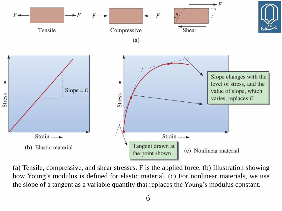
(a) Tensile, compressive, and shear stresses. F is the applied force. (b) Illustration showing
how Young’s modulus is defined for elastic material. (c) For nonlinear materials, we use
the slope of a tangent as a variable quantity that replaces the Young’s modulus constant.

7
Section 6.3
The Tensile Test: Use of the Stress-Strain Diagram
Young’s modulus (Modulus of elasticity or elastic modulus) - The slope of
the linear part of the stress-strain curve in the elastic region (E).
Stiffness - A measure of a material’s resistance to elastic deformation.
Stiffness is the slope of a load-displacement curve and is proportional to the
elastic modulus. It depends on the geometry of the component under
consideration, whereas the elastic modulus is a materials property. The
inverse of stiffness is known as compliance.
Shear modulus (G) - The slope of the linear part of the shear stress-shear
strain curve.
Engineering stress - The applied load, or force, divided by the original
cross-sectional area of the material.
Engineering strain - The amount that a material deforms per unit length in a
tensile test.

8
A unidirectional force is applied to a specimen in the tensile test by means of the
moveable crosshead. The cross-head movement can be performed using screws or a
hydraulic mechanism.
9
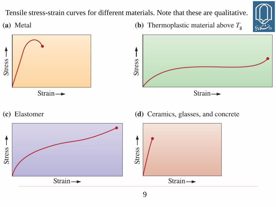
Tensile stress-strain curves for different materials. Note that these are qualitative.

10

1111

12

13
Section 6.4
Properties Obtained from the Tensile Test
Elastic limit - The magnitude of stress at which plastic deformation
commences.
Yield strength - The level of stress above which a material begins to show
permanent deformation.
Tensile strength - The stress that corresponds to the maximum load in a
tensile test.
14
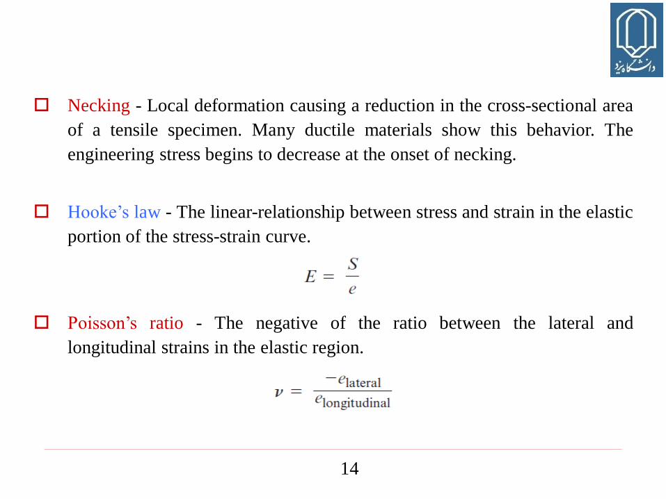
Necking - Local deformation causing a reduction in the cross-sectional area
of a tensile specimen. Many ductile materials show this behavior. The
engineering stress begins to decrease at the onset of necking.
Hooke’s law - The linear-relationship between stress and strain in the elastic
portion of the stress-strain curve.
Poisson’s ratio - The negative of the ratio between the lateral and
longitudinal strains in the elastic region.

15
Modulus of resilience (Er) - The maximum elastic energy absorbed by a
material when a load is applied.
Tensile toughness - The area under the true stress–true strain tensile test
curve. It is a measure of the energy required to cause fracture under tensile
test conditions.
Ductility - The ability of a material to be permanently deformed without
breaking when a force is applied.

16
(a) Determining the 0.2% offset yield strength in gray cast ion, and
(b) upper and lower yield point behavior in a low-carbon steel.

17
Localized deformation of a ductile material during a tensile test produces a necked
region. The micrograph shows necked region in a fractured sample.

18
Typical yield strength values for different engineered materials.

19

20
Comparison of the elastic behavior
of steel and aluminum. For a given
stress, aluminum deforms elastically
three times as much as does steel.

21
Range of elastic moduli for different engineered materials.
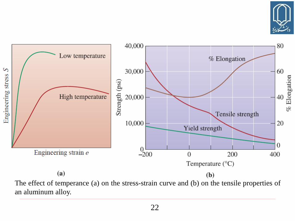
22
The effect of temperance (a) on the stress-strain curve and (b) on the tensile properties of
an aluminum alloy.

23
Section 6.5
True Stress and True Strain
True stress - The load divided by the actual cross-sectional area of the
specimen at that load.
True strain - The strain calculated using actual and not original dimensions.

24
(a) The relation between the true stress–true strain diagram and engineering stress-
engineering strain diagram. The curves are nominally identical to the yield point. The true
stress corresponding to the ultimate tensile strength (UTS) is indicated. (b) Typically true
stress–strain curves must be truncated at the true stress corresponding to the ultimate
tensile strength, since the cross-sectional area at the neck is unknown.

25
Section 6.6
Hardness of Materials
Hardness test - Measures the resistance of a material to penetration by a
sharp object.
Macrohardness - Overall bulk hardness of materials measured using loads
more than 2 N.
Microhardness Hardness of materials typically measured using loads less
than 2 N using such test as Knoop (HK).
Nano-hardness - Hardness of materials measured at 1–10 nm length scale
using extremely small (~100 µN) forces.

26
Indentors for the Brinell and Rockwell hardness tests

27

28
Section 6.7
Strain Rate Effects and Impact Behavior
Impact test - Measures the ability of a material to absorb the sudden
application of a load without breaking.
Impact loading - Application of stress at a very high strain rate (~ > 100 s-1).
Impact energy - The energy required to fracture a standard specimen when
the load is applied suddenly.
Impact toughness - Energy absorbed by a material, usually notched, during
fracture, under the conditions of impact test.

29
The impact test: (a) The Charpy and Izod tests, and (b) dimensions of typical specimens.

30
Section 6.9
Fatigue
Fatigue - The lowering of strength or failure of a material due to repetitive
stress which may be above or below the yield strength.
Beach or clamshell marks - Patterns often seen on a component subjected to
fatigue.

31
Fatigue fracture surface. (a) At low magnifications, the beach mark pattern indicates
fatigue as the fracture mechanism. The arrows show the direction of growth of the crack
front, whose origin is at the bottom of the photograph. (b) At very high magnifications,
closely spaced striations formed during fatigue are observed (x 1000).
32
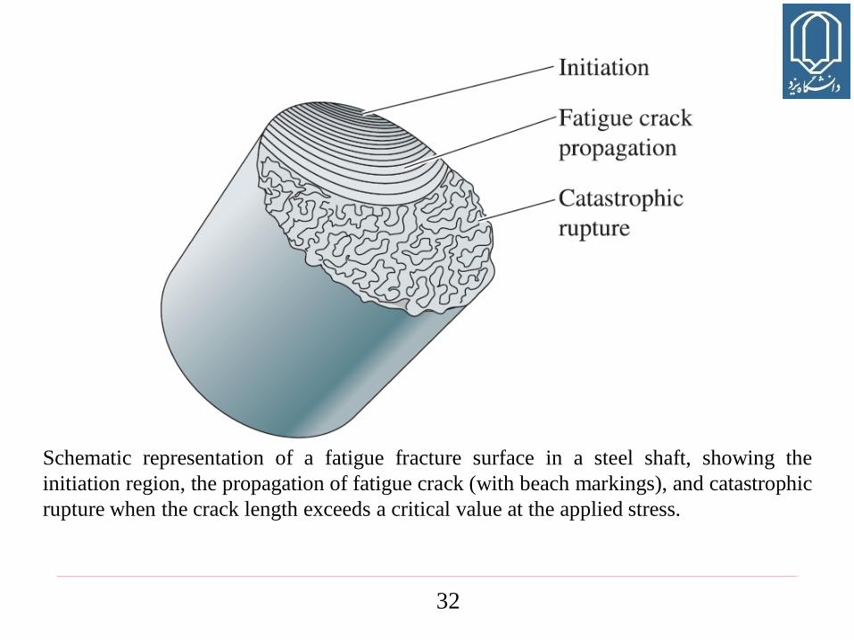
Schematic representation of a fatigue fracture surface in a steel shaft, showing the
initiation region, the propagation of fatigue crack (with beach markings), and catastrophic
rupture when the crack length exceeds a critical value at the applied stress.

33
Rotating cantilever beam test - An older test for fatigue testing.
M: the bending moment
D: the specimen diameter
L: the distance between the bending force location and the support
F: the load

34
Example 6.1 Fatigue Failure Analysis of a Crankshaft
A crankshaft in a diesel engine fails. Examination of the crankshaft reveals no
plastic deformation. The fracture surface is smooth. In addition, several other
cracks appear at other locations in the crankshaft. What type of failure
mechanism would you expect?
Example 6.1 SOLUTION
Since the crankshaft is a rotating part, the surface experiences cyclical loading.
We should immediately suspect fatigue. The absence of plastic deformation
supports our suspicion. Furthermore, the presence of other cracks is consistent
with fatigue; the other cracks didn’t have time to grow to the size that produced
catastrophic failure. Examination of the fracture surface will probably reveal
beach marks or fatigue striations.
35
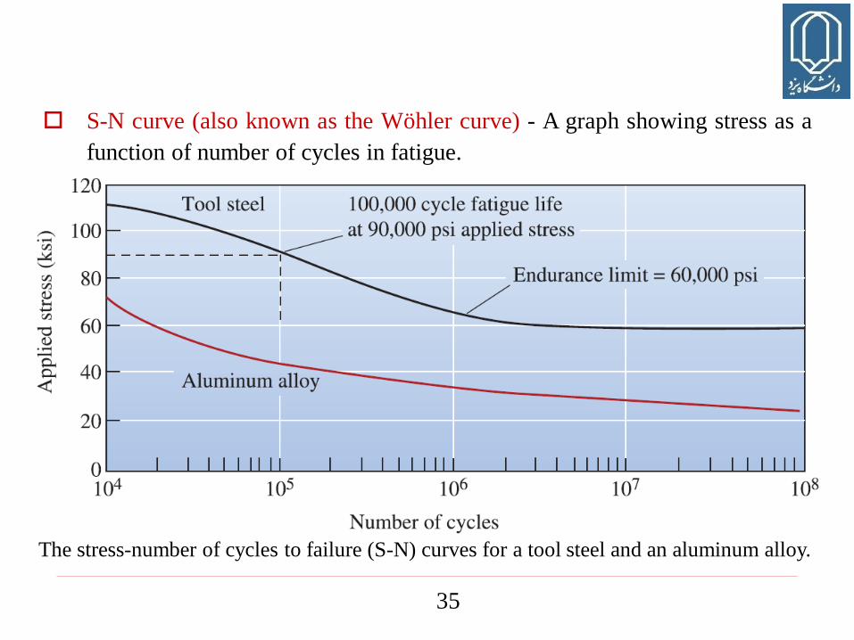
The stress-number of cycles to failure (S-N) curves for a tool steel and an aluminum alloy.
S-N curve (also known as the Wöhler curve) - A graph showing stress as a
function of number of cycles in fatigue.

36
Section 6.10
Creep
Creep - A time dependent, permanent deformation at high temperatures,
occurring at constant load or constant stress.
Creep rate - The rate at which a material deforms when a stress is applied at
a high temperature.
Creep test - Measures the resistance of a material to deformation and failure
when subjected to a static load below the yield strength at an elevated
temperature.