the south african grid code the network code - … · 4 the south african grid code – network...
TRANSCRIPT

1 The South African Grid Code – Network Code Rev 7.0 – March 2008
The South African Grid Code
The Network Code
Version 7.0
2 The South African Grid Code – Network Code Rev 7.0 – March 2008
Table of Contents Paragraph No./Title Page Number
1. Introduction ...................................................................................................4
2. Applications for transmission connections ....................................................4
3. Connection conditions...................................................................................4 3.1 Generator connection conditions.........................................................................................4
3.1.1 Protection (GCR1) .....................................................................................................7 3.1.2 Ability to perform unit islanding (GCR2) ....................................................................8 3.1.3 Excitation system requirements (GCR3) ...................................................................8 3.1.4 Reactive capabilities (GCR4) ....................................................................................9 3.1.5 Multiple unit tripping (MUT) risks (GCR5)..................................................................9 3.1.6 Governing (GCR6)...................................................................................................11 3.1.7 Restart after power station black-out (GCR7) .........................................................14 3.1.8 Black starting (GCR8)..............................................................................................14 3.1.9 External supply disturbance withstand capability (GCR9).......................................15 3.1.10 Deleted [2005/08] (GCR 10)....................................................................................15 3.1.11 Emergency unit capabilities (GCR11) .....................................................................15 3.1.12 Facility for independent generator action (GCR12).................................................15 3.1.13 Automatic under-frequency starting.........................................................................15 3.1.14 Testing and compliance monitoring.........................................................................15 3.1.15 Non-compliance suspected by the System Operator ..............................................16 3.1.16 Unit modifications ....................................................................................................16 3.1.17 Equipment requirements .........................................................................................17
3.2 Distributors and end-use customers..................................................................................17 3.2.1 Protection.................................................................................................................17 3.2.2 Power factor.............................................................................................................17 3.2.3 Fault levels...............................................................................................................18 3.2.4 Distributor or end-use customer network performance ...........................................18 3.2.5 Equipment requirements .........................................................................................18
4. Service provider design and service level requirements .............................19 4.1 Equipment design standards.............................................................................................19 4.2 Clearances ........................................................................................................................19 4.3 CT and VT ratios, accuracies and cores ...........................................................................20 4.4 Standard busbar arrangements and security criteria ........................................................20 4.5 Motorised isolators ............................................................................................................20 4.6 Earthing and surge protection ...........................................................................................20 4.7 Telecontrol.........................................................................................................................21 4.8 Transformer tap change ....................................................................................................21 4.9 NTC obligations towards nuclear power stations ..............................................................21 4.10 Substation drawings ..........................................................................................................21 4.11 Recorders ..........................................................................................................................22 4.12 HV yard breaker operating times and synchronisation facilities .......................................22 4.13 Fault levels ........................................................................................................................22 4.14 The TNSP’s delivered QOS ..............................................................................................23
5. Service provider protection requirements ...................................................23 5.1 Equipment protection requirements ..................................................................................23
5.1.1 Feeder protection: 220kV and above ......................................................................23 5.1.2 Feeder protection: 132kV and below, at TNSP substations....................................25 5.1.3 Teleprotection requirements....................................................................................25 5.1.4 Transformer and reactor protection .........................................................................26 5.1.5 Transmission busbar protection ..............................................................................26 5.1.6 Transmission bus coupler and bus section protection ............................................26 5.1.7 Transmission shunt capacitor protection.................................................................27

3 The South African Grid Code – Network Code Rev 7.0 – March 2008
5.1.8 Over-voltage protection ...........................................................................................27 5.1.9 Ancillary protection functions...................................................................................27
5.2 System protection requirements........................................................................................28 5.2.1 Under-frequency load shedding ..............................................................................28 5.2.2 Out-of-step tripping..................................................................................................28 5.2.3 Under-voltage load shedding...................................................................................28 5.2.4 Sub-synchronous resonance protection..................................................................28
5.3 Protection system performance monitoring.......................................................................28 6. Nomenclature .............................................................................................29
7. TS planning and development ....................................................................29 7.1 Planning process...............................................................................................................29 7.2 Identification of the need for TS development...................................................................29 7.3 Forecasting the demand....................................................................................................30 7.4 TS development plan ........................................................................................................30 7.5 Development investigation reports ....................................................................................30 7.6 Technical limits and targets for long-term planning purposes...........................................31
7.6.1 Voltage limits and targets ........................................................................................31 7.6.2 Other targets for long-term planning purposes........................................................32 7.6.3 Reliability criteria for long-term planning purposes .................................................33 7.6.4 Contingency criteria for long-term planning purposes.............................................33 7.6.5 Integration of power stations ...................................................................................33
7.7 Criteria for network investments........................................................................................34 7.7.1 Least economic cost criteria ....................................................................................34 7.7.2 Cost reduction investments .....................................................................................35 7.7.3 Statutory investments ..............................................................................................35
7.8 Mitigation of network constraints .......................................................................................36 7.9 Special customer requirements for increased reliability....................................................37
8. Network maintenance .................................................................................37 APPENDIX 1: Electrical drawing symbols set and layout conventions.......................................38 APPENDIX 2: Surveying, monitoring and testing for generators................................................39 APPENDIX 3: Transmission service application form.................................................................57

4 The South African Grid Code – Network Code Rev 7.0 – March 2008
1. Introduction (1) This code contains connection conditions for generators, distributors and end-use customers, and the standards used to plan and develop the Transmission System (TS). 2. Applications for transmission connections (1) A customer seeking connection to the TS or modifications to existing TS connections shall apply in writing to the NTC to the address specified in the Preamble. The customer shall provide all the relevant information requirements specified in the Information Exchange Code at time of application. (2) The NTC shall provide quotes for new connections (or for upgrading existing connections) according to the approved tariff methodology as per the Tariff Code and within the following time frames (specified in working days):
< R35m project ≥ R35m project Connection service Budget quote
≤20 Negotiated at ≤66
Connection service Firm quote
≤66 Negotiated
Network service Budget and firm quotes
≤20 ≤20
(3) Customers may request provisional quote information from the NTC, which shall be provided without commitment and without detailed studies. (4) The time periods for contracting and for connecting/upgrading customer connections shall be negotiated and agreed upon upfront, between the relevant TNSP and the customer in every instance. Where the NTC determines that the customer is required to connect to the assets of an independent TNSP, the NTC shall come to an agreement with the relevant TNSP to provide the network connection service to the customer. (5) The NTC shall use the standard application form attached as Appendix 3, for the processing of applications, which should be read in conjunction with the information provision requirements as specified in the Information Exchange Code. (6) Where there is system development or where the provision of access to one customer will have a major cost impact on other customers, the NTC shall notify the affected parties well in advance. If a dispute arises regarding the funding of these expenses, the matter shall be referred and refer the matter to the NERSA for a decision. The NERSA shall decide on time frames as part of this decision-making process in consultation with the affected participants. 3. Connection conditions (1) This section specifies the minimum technical and design requirements that customers shall adhere to when connected to or seeking connection to the TS, or for embedded generators or co-generators. 3.1 Generator connection conditions (1) This section defines minimum requirements for units of the participants that are connected to the TS and other generators defined in the Governance Code, section 4, which are required to comply with the Grid Code.

5 The South African Grid Code – Network Code Rev 7.0 – March 2008
(2) Compliance with a Grid Code requirement (GCR) shall be applicable to a unit/power station depending on rated capacity as specified in tables 1(a) and (b). Where a generator is required to comply with a GCR, it shall comply with all the requirements as specified in the relevant section. (3) The System Operator shall evaluate and specify the need for optional IPS requirements wherever indicated in tables 1(a) and (b). The System Operator shall on request make available the information pertaining to the decision. Table 1(a) Summary of the requirements applicable to specific ratings of non-hydro units
Grid code requirement Units other than hydro (MVA rating) <20 20 to <100 100 to <200 200 to <300 300 - <800 >=800
GCR1 Protection - Backup impedance Yes Yes Yes Yes Yes Yes - Loss of field - Depends on IPS
Requirements Yes Yes Yes Yes
- Pole slipping - Depends on IPSRequirements
Depends on IPS Requirements
Depends on IPS Requirements
Depends on IPS Requirements
Depends on IPS Requirements
- Trip to house load - - Depends on IPS Requirements
Depends on IPS Requirements
Yes Yes
- Gen trfr backup earth fault Yes Yes Yes Yes Yes Yes - HV breaker fail Yes Yes Yes Yes Yes Yes - HV breaker pole
disagreement Depends on IPS Requirements
Depends on IPS Requirements
Depends on IPS Requirements
Depends on IPS Requirements
Depends on IPS Requirements
Depends on IPS Requirements
- Unit Switch-onto-standstill protection
Depends on IPS Requirements
Depends on IPSRequirements
Yes Yes Yes Yes
- Main protection only Yes Yes Depends on IPS requirements
- - -
- Main protection with monitoring system or main and backup
- - Depends on IPS Requirements
Depends on IPS Requirements
- -
- Main and backup protection with monitoring system
- - - Depends on IPS Requirements
Yes
- Reverse power Depends on IPS Requirements
Yes Yes Yes Yes Yes
GCR2 Ability to island - - Depends on IPS Requirements
Yes Yes Yes
GCR3 Excitation system requirements Yes Yes Yes Yes Yes Yes - Power system stabiliser Yes Yes Yes Yes Yes Yes
- Limiters - Depends on IPSRequirements
Yes Yes Yes Yes
GCR4 Reactive capabilities Depends on IPS Requirements
Depends on IPSRequirements
Yes Yes Yes Yes
GCR5 Multiple unit tripping If the total station output is greater than the single largest contingency as defined for instantaneous reserve
GCR6 Governing Depends on IPS Requirements
Yes Yes Yes Yes Yes
GCR7 Restart after station blackout - Depends on IPS Requirements
If the total station output is greater than the single largest contingency as defined for instantaneous reserve
If more than 1 unit at station
GCR8 Black starting - If agreed If agreed If agreed If agreed If agreed GCR9 External supply disturbance
withstand capacity Depends on IPS Requirements
If more than 5 unit at station
If the total station output is greater than the single largest contingency as defined for instantaneous reserve
If more than 1 unit at station
GCR10
Deleted [2005/08]
GCR11 Emergency unit capabilities Depends on IPS Requirements
Depends on IPS Requirements
Yes Yes Yes Yes
GCR12 Independent action for control in system island
- - Depends on IPS Requirements
Yes Yes Yes

6 The South African Grid Code – Network Code Rev 7.0 – March 2008
Table 1(b) Summary of the requirements applicable to specific ratings of hydro units Grid code requirement Hydro units (MVA rating) <20 20 to <100 100 to <200 200 to <300 300 - <800 >=800
GCR1 Protection - Backup impedance ] Yes Yes Yes Yes Yes - Loss of field - Depends on IPS
Requirements Yes Yes Yes Yes
- Pole slipping - Depends on IPS Requirements
Depends on IPS Requirements
Depends on IPS Requirements
Depends on IPS Requirements
Depends on IPS Requirements
Trip to house load - - - - - -
- Gen trfr backup earth fault Yes Yes Yes Yes Yes Yes - HV breaker fail Yes Yes Yes Yes Yes Yes - HV breaker pole
disagreement Depends on IPS Requirements
Depends on IPS Requirements
Depends on IPS Requirements
Depends on IPS Requirements
Depends on IPS Requirements
Depends on IPS Requirements
- Unit Switch-onto-standstill protection
Depends on IPS Requirements
Yes Yes Yes Yes
- Main protection only Yes Yes Depends on IPS requirements
- - -
- Main protection with monitoring system or main and backup
- - Depends on IPS Requirements
Depends on IPS requirements
- -
- Main and backup protection with monitoring system
- - - Depends on IPS requirements
Yes
- Reverse power Depends on IPS Requirements
Yes Yes Yes Yes Yes
GCR2 Ability to island - - - - - - GCR3 Excitation system requirements Yes Yes Yes Yes Yes Yes - Power system stabiliser Yes Yes Yes Yes Yes Yes
- Limiters - Depends on IPS Requirements
Yes Yes Yes Yes
GCR4 Reactive capabilities Depends on IPS Requirements
Depends on IPS Requirements
Yes Yes Yes Yes
GCR5 Multiple unit tripping - Depends on IPS Requirements
If the total station output is greater than the single largest contingency as defined for instantaneous reserve
If more than 1 unit at station
GCR6 Governing Depends on IPS Requirements
Yes Yes Yes Yes Yes
GCR7 Restart after station blackout - Depends on IPS Requirements
If the total station output is greater than the single largest contingency as defined for instantaneous reserve
If more than 1 unit at station
GCR8 Black starting - If agreed If agreed If agreed If agreed If agreed GCR9 External supply disturbance
withstand capacity Depends on IPS Requirements
If more than 5 unit at station
If the total station output is greater than the single largest contingency as defined for instantaneous reserve
If more than 1 unit at station
GCR10 Deleted [2005/08]
GCR11 Emergency unit capabilities Depends on IPS Requirements
Depends on IPS Requirements
Yes Yes Yes Yes
GCR12 Independent action for control in system island
- - Depends on IPS Requirements
Yes Yes Yes
(4) The TNSP shall, subject to the signing of the necessary agreements as mentioned in section
2, make available a point of connection to any requesting generator. (5) For new units >1000 MW special consideration shall be given to the impact of these risks on
future System Operator costs, e.g. for ancillary services. The System Operator is to quantify these expected costs to the NERSA as an input to the licensing process.
(6) Applicability of each of the following GCR sections shall be as per tables 1(a) and (b).

7 The South African Grid Code – Network Code Rev 7.0 – March 2008
3.1.1 Protection (GCR1) (1) A generator transformer, unit transformer, associated busbar ducts and switchgear shall be equipped with well-maintained protection functions, to rapidly disconnect appropriate plant sections should a fault occur within the relevant protection zones that may affect the TS. (2) The following requirements are associated with each of the protection functions mentioned in tables 1(a) and (b): Backup impedance An impedance facility with a reach greater than the impedance of the generator transformer shall be used. This shall operate for phase faults in the unit, in the HV yard or in the adjacent transmission lines, with a suitable delay for cases when the corresponding main protection fails to operate. Loss of field The generator shall provide a facility to detect loss of excitation on a unit and initiate a unit trip. The type of facility to be implemented shall be agreed with the NTC. Pole slipping facility Units shall be fitted with a facility protecting against pole slipping that matches the system requirements, where the System Operator determines that it is required. Reverse power This protection shall operate in the event of a unit inadvertently importing power from the IPS. The unit shall be disconnected from the IPS. Trip to house load All units built after the implementation of the Grid Code shall island when required. Units built before the implementation of the Grid Code that are equipped with an HP bypass facility shall island when required and must have this protection function installed.This protection shall operate in the event of a complete loss of connectivity, e.g. if all the feeder breakers open at a power station. Power flow into the system is cut off and the generators will accelerate. Protection schemes shall be provided to disconnect generating units from the TS busbar before the inter-unit power swings will trip units. The units shall island, feeding their own auxiliaries. When system conditions have been restored, the islanded units can be resynchronised to the system. Generator transformer HV backup earth fault protection This is an IDMT facility that shall monitor the current in the generator transformer neutral connection. It can detect earth faults in the transformer HV side or in the adjacent network. The back-up earth fault facility shall trip the HV circuit breaker. HV breaker fail protection The “breaker fail” protection shall monitor the HV circuit breaker's operation for protection trip signals, i.e. fault conditions. If a circuit breaker fails to open and the fault is still present after a specific time delay (maximum 150 ms), it shall trip the necessary adjacent circuit breakers. HV pole disagreement protection The pole disagreement protection shall operate in the cases where one or two poles of a circuit breaker fail to operate after a trip or close signal. Note: In cases where the three poles of a circuit breaker are mechanically coupled, pole disagreement protection is made redundant and shall not be provided. Unit switch onto standstill protection This protection shall be installed in the HV yard substation or in the unit protection panels. If this protection is installed in the unit protection panels then the DC supply for the protection and that used for the circuit breaker closing circuit shall be the same. This protection safeguards the generator against an unintended connection to the TS (back energisation) when at standstill, at low speed or when inadequately excited.

8 The South African Grid Code – Network Code Rev 7.0 – March 2008
(3) In addition, should system conditions dictate, the System Operator shall determine other capital protection requirements in consultation with the generator. This equipment may be installed at the relevant power station, and be maintained by the relevant generator. (4) Any dispute as to the allocation of costs for the equipment identified in clause 3 above shall be decided in terms of the dispute resolution mechanism in the Governance Code. (5) Where generator breakers are provided (on the LV side), tripping and fault clearing times, including breaker interruption time, shall not exceed 120 ms plus an additional 30 ms for DC offset decay. (6) Where so designed, earth fault clearing times for high-resistance earthed systems may exceed the tripping times of clause 5 above. (7) The System Operator shall co-ordinate all protection interfaces between the generator and the TNSP. (8) The settings of all the protection tripping functions on the unit protection system of a unit, relevant to IPS performance and as agreed with each generator in writing, shall be co-ordinated with the transmission protection settings. These settings shall be agreed between the TNSP and each generator, and shall be documented and maintained by the generator, with the reference copy, which reflects the actual plant status at all time, held by the TNSP. The generator shall control all other copies. (9) A unit may be disconnected from the TS in response to conditions at the point of connection that will result in plant damage. Protection setting documents shall illustrate plant capabilities and the relevant protection operations. (10) Participants shall ensure that competent persons shall carry out testing, commissioning and configuration of protection systems. Prototype and routine testing shall be carried out as defined in Appendix 2 A2.3.1. (11) Generators shall communicate any work on the protection circuits interfacing with transmission protection systems (e.g. bus zone) to the System Operator before commencing the work. This includes work done during a unit outage. 3.1.2 Ability to perform unit islanding (GCR2) (1) Units that do not have black start or self start capabilities must island when required except if the unit was constructed before the implementation of the Grid Code and without an HP bypass facility designed for islanding. (2) Unit islanding shall be contracted as an ancillary service. The procedure for testing is given in Appendix 2, A2.3.2. 3.1.3 Excitation system requirements (GCR3) (1) A unit shall have a continuously acting automatic excitation control system (AVR). The AVR shall provide constant terminal voltage control of the unit over the entire operating range of the unit. (Note that this does not include the possible influence of a power system stabiliser.) Excitation control systems shall comply with the requirements specified in IEC 60034, IEEE 421 or any other standard agreed to by the System Operator. (2) The excitation control system shall be equipped with a load angle limiter and flux limiter except for installed AVR equipment up to and including analogue electronic technology. (3) The excitation system shall have a minimum excitation ceiling limit of 1,6 pu rotor current, where 1 p.u. is the rotor current required to operate the unit at rated load and at rated power factor as defined in IEC 60034, IEEE421 or any other standard agreed to by the System Operator.

9 The South African Grid Code – Network Code Rev 7.0 – March 2008
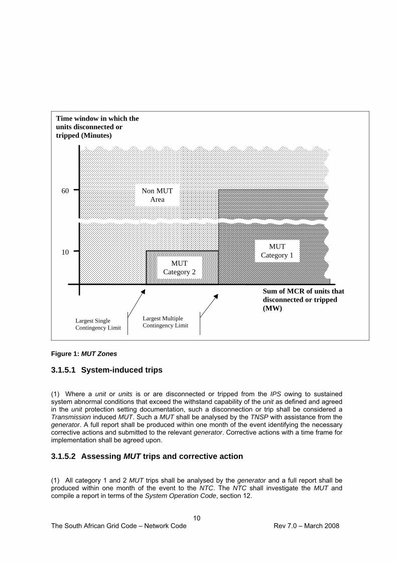
(4) The System Operator shall determine the settings of the excitation system in consultation with each generator. These settings shall be documented, with the controlled copy held by the System Operator. The generators shall control all other copies. The procedure for this is shown in Appendix 2, A2.3.3. (5) In addition, the unit shall be capable of operating in the full range as indicated in the capability diagram supplied as part of the Information Exchange Code section 3. Test procedures are shown in Appendix 2, A2.3.3. (6) Units shall be capable of delivering constant active power output under steady state conditions for voltage changes in the normal operating range (specified in the system operations code). (7) All units built after the implementation of the Grid Code shall be equipped with power system stabilisers as defined in IEC 60034, IEEE421 or any other standard agreed to by the System Operator. The requirements for other excitation control facilities and AVR refurbishment shall be determined in conjunction with the System Operator. (8) Generators shall carry out routine and prototype response tests on excitation systems as indicated in Appendix 2, and in accordance with IEC60034-16-3. 3.1.4 Reactive capabilities (GCR4) (1) Units build after the implementation of the Grid Code shall be designed to supply rated power output (MW) for power factors ranging between 0.85 lagging and 0.95 leading or otherwise as agreed with the System Operator in the use-of-system agreement. Power factor readings refer to the HV side of the unit step-up transformer. (2) Reactive output shall be fully variable between these limits under AVR, manual or other control. (3) Generators shall carry out routine and prototype response tests to demonstrate reactive capabilities as indicated in Appendix 2, A2.3.4. 3.1.5 Multiple unit tripping (MUT) risks (GCR5) (1) A power station and its units shall be designed, maintained and operated to minimise the risk of more than one unit being tripped from one common cause within the time window and load limits described below. Two categories of multiple units tripping are used to categorise the impact on the IPS. • Category 1: Unplanned disconnection or tripping of more than one unit
instantaneously or within a one hour window, where the total maximum continuous rating (MCR) of those units exceeds the largest credible multiple contingencies.
• Category 2: Unplanned disconnection or tripping more than one unit instantaneously or within ten minutes, where the total MCR of those units exceeds the largest single contingency.
(2) The power station shall be designed such that no MUT category 1 trip risk can occur and a MUT category 2 trip will not occur more than once in ten years. (3) The power station shall calculate the minimum number of units required to trip for each category and identify potential common elements in the power station that can cause an MUT category 1 or 2 trip. The power station shall inform the System Operator of these causes with corrective actions planned. (4) Should the System Operator determine that a power station presents an unacceptable MUT risk for the network, the relevant generator and the System Operator shall agree on the corrective action required to reduce the MUT risk and time frames within which to comply.
10 The South African Grid Code – Network Code Rev 7.0 – March 2008
MUTCategory 2
MUTCategory 1
Non MUTArea
Sum of MCR of units thatdisconnected or tripped(MW)
Time window in which theunits disconnected ortripped (Minutes)
10
60
Largest SingleContingency Limit
Largest MultipleContingency Limit
Figure 1: MUT Zones 3.1.5.1 System-induced trips
(1) Where a unit or units is or are disconnected or tripped from the IPS owing to sustained system abnormal conditions that exceed the withstand capability of the unit as defined and agreed in the unit protection setting documentation, such a disconnection or trip shall be considered a Transmission induced MUT. Such a MUT shall be analysed by the TNSP with assistance from the generator. A full report shall be produced within one month of the event identifying the necessary corrective actions and submitted to the relevant generator. Corrective actions with a time frame for implementation shall be agreed upon. 3.1.5.2 Assessing MUT trips and corrective action
(1) All category 1 and 2 MUT trips shall be analysed by the generator and a full report shall be produced within one month of the event to the NTC. The NTC shall investigate the MUT and compile a report in terms of the System Operation Code, section 12.

11 The South African Grid Code – Network Code Rev 7.0 – March 2008
(2) Corrective action shall be implemented by the participants in terms of the investigation report of the System Operator. (3) Typical areas of MUT are the following: • Relaying and other equipment powered from a common DC supply that is sensitive to
disturbances to the supply such as AC onto DC, which causes the tripping of a unit or units
• Relaying or other equipment supplied from a common DC supply that will malfunction and trip a unit or units in the event of a loss of DC supply
• The loss of AC supply for up to two hours to an uninterruptible power supply (UPS), leading to the malfunction of the UPS or its associated load equipment leading to the trip of a unit or units
• An earth mat with insufficient capacity or capability to successfully direct lightning or switching surges away from sensitive equipment leading to the trip of a unit or units
• The use of mercury-type Buchholz facilities that are sensitive to earth tremors leading to the tripping of units
• DC systems common to generating units without proper earth fault location equipment • Common compressed air plant without proper provision of isolation, storage and non-
return valve systems (4) Routine and prototype response tests shall be carried out to demonstrate MUT withstand capabilities as indicated in Appendix 2, A2.3.5. 3.1.6 Governing (GCR6) 3.1.6.1 Design requirements
(1) All units above 50 MVA shall have an operational governor capable of responding according to the minimum requirements set out in this section. 3.1.6.2 System frequency variations
(1) The nominal frequency of the TS is 50 Hz and is normally controlled within the limits as defined in the System Operations Code, section 9. The system frequency could rise or fall in exceptional circumstances and turbo-alternator units must be capable of continuous normal operation for the minimum operating range indicated in figure 2 and described in section 3.1.6. (2) The design of turbo-alternator units must enable continuous operation, at up to 100% active power output, within this range. (3) Tripping times for units in the range of 47.5Hz to 48.5Hz shall be as agreed with the system operator. Sections 3.1.6.3 to 3.1.6.5 shall be used as guidelines for these tripping times.

12 The South African Grid Code – Network Code Rev 7.0 – March 2008
SystemFrequency(Hz)
45
46
47
48
49
50
51
52
53
0.01 0.1 1 10 100 1000 10000
Nominal(50 Hz)
ContinuousOperating Range(48.5 Hz to 51.5Hz)
MINIMUM OPERATING RANGE FOR TURBO-ALTERNATORS
Time (Minutes)
H1H2
L3L2
L1
Figure 2: Time vs. system frequency plot, minimum operating range of a unit
(4) Hydro-alternator units must be capable of continuous normal operation for high frequency conditions described in section 3.1.6.4 and low frequency conditions as described in 3.1.6.6.
3.1.6.3 High frequency requirements for turbo-alternators
(1) Synchronised units shall respond by automatically reducing active power if the frequency is above 50.5 Hz. Governing shall be set to give a 4% droop characteristic. The response shall be fully achieved within 10 seconds and shall be sustained for the duration of the frequency excursion. The unit shall respond to the full designed minimum operational capability of the unit at the time of the occurrence and at least 15% of MCR. Those units that are contracted for Instantaneous Reserve low frequencies shall provide the capacity for Instantaneous Reserve for high frequencies between the applicable dead-band and 50.5 Hz. These units are required to respond at least the same contracted capacity for low frequencies and according to the agreed droop characteristic. The response is required fully within 10 seconds, to an increase in system frequency above the allowable. This response must be sustained for at least 10 minutes (see also figure 3). (2) Over-frequency conditions in the range 51.5 to 52 Hz (Stage H1) The unit shall be designed to run for at least 10 minutes over the life of the plant if the frequency goes above 51.5 Hz but is less than 52 Hz. If the system frequency is greater than 51.5 Hz for 1 minute and the unit is still generating power it can be islanded or tripped to protect the unit. Power stations shall stagger the tripping of the units and the philosophy for tripping shall be approved by the System Operator. (3) Over-frequency conditions in the range above 52 Hz (Stage H2) The unit shall be designed to run for at least 1 minute over the life of the plant if the frequency is above 52 Hz. If the system frequency is greater than 52 Hz for 10 seconds and the unit is still generating power it can be islanded or tripped to protect the unit. Power stations shall stagger the tripping of the units and the philosophy for tripping shall be approved by the System Operator. 3.1.6.4 High frequency requirements for hydro alternators

13 The South African Grid Code – Network Code Rev 7.0 – March 2008
(1) The unit shall be designed to run for at least 5 seconds over the life of the plant if the frequency goes above 54 Hz, hence the hydro-alternator units must be able to operate for at least 1 second in this range. (2) If the system frequency increases to 54 Hz for longer than 1 second the unit can be tripped to protect the unit. 3.1.6.5 Low frequency requirements for turbo-alternator units
(1) Units shall be designed to be capable of a minimum response of 3% of MCR sent out within 10 seconds of a frequency drop over the range from minimum load to 97% of MCR sent out, as illustrated in figure 3. The response shall be sustained for at least 10 minutes. All low frequency conditions shall be limited to the over fluxing limits specified in the Information Exchange Code, Appendix 3. (2) Low frequency in the range 48.5 to 48.0 Hz (StageL1) The unit shall be designed to run for at least 10 minutes over the life of the plant if the frequency goes below 48.5 Hz but greater than 48.0 Hz. The unit shall be able to operate for at least 1 minute while the frequency is in this range. If the system frequency is less than 48.5 Hz for 1 minute the unit can be islanded or tripped to protect the unit. Power stations shall stagger the tripping of the units and the philosophy for tripping shall be approved by the System Operator. (3) Low frequency in the range 48.0 to 47.5 Hz (Stage L2) The unit shall be designed to run for at least 1 minute over the life of the plant if the frequency goes below 48.0 Hz but is greater than 47.5 Hz. If the system frequency is less than 48.0 Hz for 10 seconds the unit can be islanded or tripped to protect the unit. Power stations shall stagger the tripping of the units and the philosophy for tripping shall be approved by the System Operator. (4) Low frequency below 47.5 Hz (Stage L3) If the system frequency falls below 47.5 Hz for longer than 6 seconds the unit can be islanded or tripped to protect the unit. 3.1.6.6 Low frequency requirements for hydro-alternator units
(1) All reasonable efforts shall be made by the generator to avoid tripping of the hydro-alternator for under frequency conditions provided that the system frequency is above or equal to 46 Hz. (2) If the system frequency falls below 46 Hz for more than 1 second it can be tripped to protect the unit. 3.1.6.7 Dead band
(1) The maximum allowable dead band shall be 0.15 Hz for governing for units contracted for instantaneous reserve and 0.5 Hz for units not contracted instantaneous reserve. No response is required from the unit while the frequency is within the dead band. (2) Generators shall carry out routine and prototype response tests on the governing systems as indicated in Appendix 2, A2.3.4. (3) Coal-fired units not equipped with a dead band facility shall have a droop of 10% or less. At 49.75 Hz a unit that does not have a dead band and does not limit the response will respond two and a half times more if the unit is on a 4% droop. If the desired response from coal-fired units is

14 The South African Grid Code – Network Code Rev 7.0 – March 2008
5% of MCR sent out at 49,75Hz, then this is equivalent to a 10% droop with no dead band. See figure 3 below. This means the effective requirements from the units are the same.
Summary of Governing Requirements
-20
-15
-10
-5
0
5
10
15
20
49 49.1 49.2 49.3 49.4 49.5 49.6 49.7 49.8 49.9 50 50.1 50.2 50.3 50.4 50.5 50.6 50.7 50.8 50.9 51
Frequency
% c
hang
e in
MC
R
InstantaneousReserve
deadband
InstantaneousReserve up
Mandatory governor response
InstantaneousReserve down
Instantaneous Reserveresponse if no deadband
Normal operating range - market responsibility
Figure 3: Graphical representation of governing requirements including responsibilities of
customers 3.1.6.8 Summary of governor requirements
Refer to section 9 of the System Operations Code. 3.1.7 Restart after power station black-out (GCR7) (1) A unit shall restart without unreasonable delay following a black-out and restoration of the external auxiliary AC supply to the HV yard provided that the following is maintained at the point of connection for the duration of the unit start-up process: • a stable supply of at least 90% of nominal voltage for units with on-load tap changers on the
generator transformers, and a stable supply of at least 95% nominal voltage for units without on-load tap changers on the generator transformers
• an unbalance between phase voltages of not more than 3% negative phase sequence • a frequency within the continuous operating range as indicated in figure 2. Generators shall reasonably co-operate with the System Operator in attempting to restart at lower voltage conditions. (2) For the purposes of this code, examples of unreasonable delay in the restart of a power station, where the supply to the power station has been restored within 2 hours, are: • restart of the first unit that takes longer than 4 hours after restart initiation • restart of the second unit that takes longer than 2 hours after the synchronising of the first unit • restarting of all other units that take longer than 1 hour, one after the other, after the
synchronising of the second unit. • delays not inherent in the design of the relevant start-up facilities and which could reasonably
be minimised by the relevant generator. (3) Generators shall carry out routine and prototype response tests to demonstrate capabilities as indicated in Appendix 2, A2.3.7. 3.1.8 Black starting (GCR8)

15 The South African Grid Code – Network Code Rev 7.0 – March 2008
(1) Generators that have declared that they have a station black start capability shall demonstrate this facility by test as described in Appendix 2, A2.3.8. The periodicity of the tests shall be determined by the System Operator, in agreement with the Generators. 3.1.9 External supply disturbance withstand capability (GCR9) (1) Any unit or power station equipment shall be designed with anticipation of the following voltage conditions at the point of connection: • A voltage deviation in the range of 90% to 110% of nominal voltage • A 3-phase voltage drop to zero for up to 0.2 seconds, to 75% for 1 second, or to 85% for 60
seconds provided that during the 3 minute period immediately following the end of the 0.2 second, 2 second, or 60 second period the actual voltage remains in the range 90% to 110% of the nominal voltage
• Unbalance between phase voltages of not more than 3% negative phase sequence and/or the magnitude of one phase not lower than 5% than any of the other two for 6 hours
• A Volt/Hz requirement of less than 1.1 p.u. • A requirement to withstand the following ARC cycle for single-phase faults on the transmission
lines connected to the power station:
1ph fault - 1ph trip - 1 second 1ph ARC dead time - 1ph ARC - 1ph fault - 3ph trip - 3 seconds 3ph ARC dead time - 3ph ARC - 1ph fault - 3ph trip - lock out. This only applies where synchronism is maintained
• A requirement to withstand the following ARC cycle for multi-phase faults (phase-to-phase or 3-phase) on the transmission lines connected to the power station: 3ph fault - 3ph trip - 3 seconds 3ph ARC dead time - 3ph ARC - 3ph fault - 3ph trip - lock out
Routine and prototype response tests shall be carried out to demonstrate capabilities as indicated in Appendix 2, A2.3.9. 3.1.10 Deleted [2005/08] (GCR 10) 3.1.11 Emergency unit capabilities (GCR11) (1) All generators shall specify their units’ capabilities for providing emergency levels 1 and 2 support under abnormal power system conditions, as detailed in the System Operation Code. 3.1.12 Facility for independent generator action (GCR12) (1) Frequency control under system island conditions shall revert to the power stations as the last resort, and units and associated plant shall be equipped to handle such situations. The power stations shall use reasonable endeavours to control the frequency between 49 and 51 Hz. 3.1.13 Automatic under-frequency starting (1) It may be agreed with the System Operator that a unit that is capable of automatically starting within 10 minutes shall have automatic under-frequency starting. This starting shall be initiated by frequency-level facilities with settings in the range 49Hz to 50Hz as specified by the System Operator. 3.1.14 Testing and compliance monitoring (1) A generator shall keep records relating to the compliance by each of its units with each section of this code applicable to that unit, setting out such information that the System Operator reasonably requires for assessing power system performance (including actual unit performance during abnormal conditions).

16 The South African Grid Code – Network Code Rev 7.0 – March 2008
(2) A generator shall review, and confirm to the System Operator, compliance by the power station or each of that generator’s units with every GCR as specified in Appendix 2. (3) A generator shall conduct tests or studies to demonstrate that each power station and each generating unit complies with each of the requirements of this code. Tests shall be carried out on new units, after every outage where the integrity of any GCR may have been compromised, to demonstrate the compliance of the unit with the relevant GCR(s). The generator shall continuously monitor its compliance in all material respects with all the connection conditions of the Grid Code. (4) Each generator shall submit to the System Operator a detailed test procedure, emphasising system impact, for each relevant part of this code prior to every test. (5) If a generator determines, from tests or otherwise, that one of its units or power stations is not complying in any material respect with one or more sections of this code, then the generator shall • promptly notify the System Operator of that fact • promptly advise the System Operator of the remedial steps it proposes to take to ensure
that the relevant unit or power station (as applicable) can comply with this code and the proposed timetable for implementing those steps
• diligently take such remedial action as will ensure that the relevant unit or power station (as applicable) can comply with this code; the generator shall regularly report in writing to the System Operator on its progress in implementing the remedial action, and
• after taking remedial action as described above, demonstrate to the reasonable satisfaction of the System Operator that the relevant unit or power station (as applicable) is then complying with this code.
(6) The System Operator may issue an instruction requiring a generator to carry out a test to demonstrate that the relevant power station complies with the Grid Code requirements. A generator may not refuse such an instruction, provided it is issued timeously and there are reasonable grounds for suspecting non-compliance. 3.1.15 Non-compliance suspected by the System Operator (1) If at any time the System Operator believes that a unit or power station is not complying with a GCR, then the System Operator shall notify the relevant generator of such non-compliance by issuing a non-conformance report (as referred to in the Governance Code) specifying the GCR concerned and the basis for the System Operator’s belief. (2) The System Operator shall specify the remedial action required from the generator as well as the time frames within which to comply with this code. (3) Any dispute arising out of such a non-conformance report shall be resolved in terms of the dispute resolution procedure described in the Governance Code. 3.1.16 Unit modifications (1) If a generator proposes to change or modify any of its units in a manner that could reasonably be expected to either affect that unit's ability to comply with this code, or changes the performance, information supplied, settings, etc., then that generator shall submit a proposal notice to the System Operator which shall • contain detailed plans of the proposed change or modification • state when the generator intends to make the proposed change or modification, and • set out the proposed tests to confirm that the relevant unit as changed or modified to
operate in the manner contemplated in the proposal, can comply with this code. (2) If the System Operator disagrees on reasonable grounds with the proposal submitted, it shall provide the relevant generator with reasons, and the System Operator and the relevant generator shall promptly meet and discuss the matter in good faith in an endeavour to resolve the disagreement.

17 The South African Grid Code – Network Code Rev 7.0 – March 2008
(3) The generator shall ensure that an agreed change or modification to a unit or to a subsystem of a unit is implemented in accordance with the relevant proposal agreed to by the System Operator. (4) The generator shall notify the System Operator promptly after an agreed change or modification to a unit has been implemented. (5) The generator shall confirm that a change or modification to any of its units as described above conforms to the relevant proposal by conducting the relevant tests, in relation to the connection conditions, promptly after the proposal has been implemented. (6) A generator shall provide the System Operator with a report in relation to any compliance test (including test results of that test, where appropriate), within 20 business days after such test has been conducted.
3.1.17 Equipment requirements (1) Where the generator needs to install equipment that connects directly with TNSP equipment, e.g. in the high voltage yard of the TNSP, such equipment shall adhere to the TNSP design requirements as set out in this code. (2) The TNSP may require customers to provide documentary proof that their connection equipment complies with all relevant standards, both by design and by testing. 3.2 Distributors and end-use customers (1) This section describes connection conditions for distributors and end-use customers. (2) The TNSP shall, subject to the signing of the necessary agreements as mentioned in section 2, make available a point of connection to any requesting customer. 3.2.1 Protection (1) Each participant shall take all reasonable steps to protect its own plant. (2) The Grid Code protection requirements are described in section 5. The detailed protection applications, insofar as the equipment of one participant may have an impact on another, shall be agreed to in writing by the relevant participants. Distributors that have customers connected directly to the TS substations are responsible for ensuring that such customers comply with the relevant protection standards. (3) The participants shall co-operate to ensure adequate protection co-ordination. (4) Customer’s protection dependability shall not be less than 99% and the customer shall ensure that QOS standards are adhered to. 3.2.2 Power factor (1) Distributors and end-use customers shall take all reasonable steps to ensure that the power factor at the point of supply is at all times 0.9 lagging or higher, unless otherwise agreed to in existing contracts. This requirement applies to each point of supply individually for customers with more than one point of supply. A leading power factor shall not be acceptable, unless specifically agreed to in writing with the System Operator. (2) Should the power factor be less than the said limit during any ten demand-integrated half-hours in a single calendar month, the participants shall co-operate in determining plans of action to rectify the situation. Overall lowest cost solutions shall be sought and implemented.

18 The South African Grid Code – Network Code Rev 7.0 – March 2008
3.2.3 Fault levels (1) The customer shall ensure his equipment is capable of operating at the specified fault levels as published by the System Operator, from time to time. (2) If customer equipment fault level ratings are or will be exceeded, the customer shall promptly notify the NTC. The NTC shall seek overall lowest cost solutions to address fault level problems. Corrective action shall be for the cost of the relevant asset owner and per the implementation plan agreed to. (3) Any dispute as to the allocation of costs for the equipment identified in clause 2 shall be decided in terms of the dispute resolution mechanism in the Governance Code. 3.2.4 Distributor or end-use customer network performance (1) The participants shall negotiate in good faith and agree on the details of acceptable levels of performance for distributor or end-use customer networks. Acceptable network performance principles shall include • performance comparable with benchmarks for similar networks • performance within the design or OEM specifications of the customer and transmission
equipment • performance at the point of connection that complies with the TNSP operating procedures • performance consistent with the outcomes of the investment criteria as described in
section 7.7 • performance that does not negatively impact on agreed levels of performance with other
customers. (2) If the distributor or end-use customer network performance falls below acceptable levels and affects the quality of supply to other customers or causes damage (direct or indirect) to the TNSP equipment, the process for dispute resolution as described in the Governance Code shall be followed. (3) The NERSA shall determine criteria for the contracting of acceptable levels of performance. (4) If distributors or end-use customers are aware that their network performance could be unacceptable as described above, they shall take reasonable steps at their own cost to overcome the shortcomings, e.g. by improving their line maintenance practices, improving protection and breaker operating times, if necessary replacing the said equipment, installing additional network breakers, changing operating procedures, installing fault-limiting devices if the number of faults cannot be reduced, etc. These changes to their networks should be effected in consultation with the TNSP regarding both the technical scope and the time frame. (5) Where QOS standards are not met, the parties shall co-operate and agree in accordance with NERSA power quality directives in determining the root causes and plans of action. 3.2.5 Equipment requirements (1) Where the distributor or end-use customer needs to install equipment that connects directly with TNSP equipment in transmission substations, such equipment shall adhere to the TNSP design requirements as set out below in section 4. (These can be at any voltage level.) (2) The TNSP may require customers to provide documentary proof that their connection equipment complies with all relevant design requirements, both by design and by testing. (3) Any TNSP, distributor or end-use customer wishing to install a new series capacitor or modify the series reactance of an existing series capacitor shall, at its expense and in accordance with the NTC’s reasonable requirements, arrange for sub-synchronous resonance, harmonic and protection co-ordination studies to be conducted to ensure that sub-synchronous resonance will not be excited in any generator. SSR becomes a potential problem if a series capacitor is installed

19 The South African Grid Code – Network Code Rev 7.0 – March 2008
between a generating unit and its load or interconnection with the grid. The closer the series compensated line is to the unit, the greater the risk because of reduced damping by the resistance of intervening lines and loads. (4) Any TNSP, distributor or end-use customer wishing to install a new shunt capacitor or modify the shunt capacitance of an existing shunt capacitor shall, at its expense and in accordance with the NTC’s reasonable requirements, arrange for harmonic resonance studies to be conducted to ensure that harmonic voltage levels do not exceed the limits specified in NRS048. (5) If the studies specified in 3.2.5 (3) or (4) indicate that a risk exists of subsynchronous resonance affecting one or more units or harmonic resonance having an impact on the TS, the party mandating the studies shall inform the System Operator before proceeding with the installation or modifications contemplated. 3.2.6 Additional reinforcement (1) A customer may request additional reinforcements to the TS over and above that which could be economically justified as described in section 7. The TNSP shall provide such reinforcements if the customer agrees to bear the costs, which shall be priced according to the provisions of the Tariff Code. 4. Service provider design and service level requirements (1) This section documents the design and other technical standards to which the service providers shall adhere. (2) The TNSP shall offer to connect and, subsequent to the signing of the relevant agreements, make available a point of connection to the TS to any requesting distributor or end-use customer. 4.1 Equipment design standards (1) Primary substation equipment shall comply with relevant IEC specifications. Application shall cater for local conditions, e.g. increased pollution levels, and should be determined by or in consultation with the relevant customer. The TNSP shall develop and maintain applicable standards for transmission substation equipment, details of which shall be supplied to customers upon request. The TNSP shall design, install and maintain equipment in accordance with the standards developed. (2) In the case of equipment operated at transmission substations at voltages of 132 kV and below, the relevant participants may agree to use standards applicable to the distributor system. (3) The TNSP shall ensure that the agreed design standards at the interfaces with customer equipment be documented. This documentation shall address the interface for the primary equipment and secondary circuits. Consideration shall also be given to possible common DC supplies, AC supplies, compressed air systems and fencing. (4) The TNSP shall provide, upon customers’ request, documentary proof that their connection equipment complies with all relevant standards, both by design and by testing. (5) The TNSP shall ensure that switching devices at or near a power station are adequate rated and capable of switching loads and fault currents without generating undue switching surges. Particular attention shall be paid to the correct switching of the generating unit HV Breaker. The TNSP shall ensure that adequate switching surge protection is provided to the generating unit as specified in table 2. Adequate safety margins shall be provided. 4.2 Clearances (1) Clearances shall comply with at least the requirements of the Occupational Health and Safety
Act.

20 The South African Grid Code – Network Code Rev 7.0 – March 2008
4.3 CT and VT ratios, accuracies and cores (1) CT and VT ratios and cores shall be determined by the asset owner in consultation with the other relevant participants. (2) A TNSP or a customer connected to the TS shall ensure that measurement equipment complies with the following accuracy classes for the purposes of operating and control of the IPS. Details of equipment, location etc., shall be contained in the operating agreement. Measurement equipment Accuracy class Current transformer (CT) 0,2 Voltage transformer (VT) 0,2 Transducer 0,5 Analogue to digital conversion, i.e. RTU 0,01
4.4 Standard busbar arrangements and security criteria (1) Substations on the TS shall be configured in accordance with the principles described in this section. (2) The standard substation arrangement shall be based on providing one busbar zone for every main transformer/line normally supplying that busbar. The TNSP shall, however, consider local conditions, type of equipment used, type of load supplied and other factors in the assessment of the required busbar redundancy. The TNSP shall also adhere to the system reliability criteria as described in section 7. (3) A circuit breaker bypass facility with single busbar selection shall be used at 275 kV on single line radial feeds to provide continuity of supply when the line breakers are being maintained. (4) A circuit breaker bypass facility with double busbar selection shall be used on new 400 kV and 765 kV lines and 275 kV lines where justified in accordance with section 7. 4.5 Motorised isolators (1) The provision of motorised isolators by the TNSP at new substations shall be based on the following: • All 765 kV, 400 kV, 275 kV and 220 kV isolators at new substations shall be motorised • Isolators of 132 kV and below shall be specified on individual merit in consultation with the
relevant customer
4.6 Earthing and surge protection (1) The TNSP shall ensure adequacy of all earthing installations to provide for • the safety of personnel and the public • the correct operation of all protection systems • agreed design and performance levels. (2) Earthing isolators shall be provided at new substations where the fault level is designed for 20 kA and above. (3) The TNSP shall provide adequate protection to limit lightning surges at the connection point to the limits listed below using the best technology methods. Note that protection has to be placed as close as possible to the point of connection. The protection shall be adequate to protect the generator unit to the rating levels specified in table 2 below. Adequate safety margins shall be provided.

21 The South African Grid Code – Network Code Rev 7.0 – March 2008
Table 2 TNSP surge protection rating levels requirement
System nominal voltage Un (kV rms)
Lightning impulse voltage at sea level (kV peak)
Switching impulse withstand at sea level (phase-to-neutral) (kV peak)
Switching impulse withstand at sea level (phase-to-phase) ( kV peak)
Sixty second power frequency withstand test at sea level (phase-to-neutral) (kV rms)
Line terminal
Neutral terminal
Line terminal Line terminal Line terminal Neutral terminal
88 380 250x 450 150 95x
132 550 110+ 650 230 38+
220 850 110+ 1050 350 38+
275 1050 110+ 850 1300 300/260° 38+
330 1300 110+ 950 1425 362/314° 38+
400 1425 110+ 1050 1530 420/364° 38+
500 1550 110+ 1175 1675 525/455° 38+
765 1950 110+ 1425 2400 800/693° 38+ Non-uniform insulation + Fully graded insulation x Partially graded insulation ° Method II testing to IEC 76-3 (U1/U2)
Bushing insulation: All bushings shall have insulation levels 10% in excess of transformer’s requirement. If
transformer ≥5 MVA, the minimum rating for bushings is 33 kV
4.7 Telecontrol (1) All participants shall be permitted to have telecontrol equipment in the substations, yards or buildings of the other participants, to perform agreed monitoring and control. The asset owner shall provide access to such equipment. 4.8 Transformer tap change (1) The TNSP shall install automatic tap changing facilities on all new transformers. (2) Transformers used on the TS at 220kV and above are normally not on automatic tap change. Transformers supplying a customer are usually on automatic tap change. Voltage levels, sensitivity and time settings and on/off auto tap changing shall be determined by the System Operator in consultation with the customer and the TNSP considering the impact on customer investment. (3) The Volts/Hertz or flux levels (Φ) at the point of connection shall meet the following requirements:
Volts/Hertz (pu)
1.1 1.125 1.15 1.175 1.2 1.225 1.25 1.275 1.3
Time (seconds)
continuous 3000 600 180 72 42 30 24 18
4.9 NTC obligations towards nuclear power stations (1) The System Operator shall provide secure off-site supplies, as requested and specified by the relevant nuclear generators and facilities in accordance with the National Nuclear Regulatory Act (Act 47 of 1999), to all TS-connected nuclear power stations and facilities. A written agreement, as per section 2.1.3 of the System Operation Code, shall be drawn up and indicators of performance are to be developed and implemented to illustrate the integrity of supply. 4.10 Substation drawings

22 The South African Grid Code – Network Code Rev 7.0 – March 2008
(1) The following set of drawings shall be made available for all points of supply by the respective asset owners, if required by the other party for purposes of connection: • Station electric diagram • Key plan • Bay layout schedules • Foundation, earth mat and trench layout • Steelwork marking plan • Security fence layout • Terrace, road and drainage layout • Transformer plinth • General arrangement • Sections • Slack span schedule • Barrier fence layout • Security lighting • Floodlighting parameter sketch • Protection details • Contour plan
(2) All drawings shall use the standard electrical symbol set defined in Appendix 1. 4.11 Recorders (1) The TNSP shall install QOS recorders as stipulated by NRS048 at the points of supply or points of connection, as agreed with the customers. (2) The TNSP shall, in consultation with customers, install disturbance recorders at locations in the network that shall enable the System Operator to adequately analyse system disturbances. (3) Access to the records shall be as specified in the Information Exchange Code, section 5.3.4. 4.12 HV yard breaker operating times and synchronisation
facilities (1) Maximum permitted unit HV breaker tripping and fault clearance times, including breaker operating times, depend on system conditions and shall be defined by the NTC. Guidelines for operating times are: • 80 ms where the point of connection is 400kV or above • 100 ms where the point of connection is 220 kV or 275 kV • 120 ms where the point of connection is 132 kV and below. (2) All new HV yards at power stations shall be equipped with synch-check relays. 4.13 Fault levels (1) The TNSP shall maintain contracted minimum fault levels at each point of supply under normal operating conditions. (2) The System Operator shall calculate maximum fault levels, before and after mitigating actions to reduce fault levels. (3) The NTC shall liase with customers as per the process defined in section 7 on how fault levels are planned to change and on the best overall solutions when equipment ratings become inadequate. Overall lowest cost solutions shall be sought and a joint impact assessment, covering all aspects, shall be done. Implementation shall be done by the relevant asset owners. The TNSP shall communicate the potential impact on the safety of people when equipment ratings are exceeded.

23 The South African Grid Code – Network Code Rev 7.0 – March 2008
4.14 The TNSP’s delivered QOS (1) The TNSP shall agree in writing with its customers, for every point of supply, on the QOS
parameters. The participants shall negotiate in good faith and agree on the details of acceptable levels of QOS. The performance shall
• comply with NRS048 as a minimum • enable distributors to comply with NRS048 standards. (2) The participants shall review the agreed QOS performance levels in accordance with the NERSA power quality directive, as updated from time to time. If the delivered QOS affects the customer’s processes or causes damage (direct or indirect) to the customer’s equipment, the process for dispute resolution as described in the Governance Code, section 6, shall be followed (3) Where the TNSP fails to meet the agreed QOS parameters due to shortcomings in its own network, it shall take reasonable steps at its own cost to overcome the shortcomings. These changes shall be effected in consultation with the customer regarding both the technical scope and the time frame. 5. Service provider protection requirements (1) This section specifies the minimum protection requirements for TNSPs as well as typical settings, to ensure adequate performance of the TS as experienced by the customers. (2) TNSP’s shall at all times ensure that the protection installations comply with the provisions of this section. (3) TNSP’s shall ensure that competent persons shall carry out testing, commissioning and configuration of protection systems. Prototype and routine testing shall be carried out as defined Appendix 2, A2.3.1. (4) TNSP’s shall conduct periodic testing of equipment and systems to ensure and demonstrate that these are performing to the design specifications. Tests procedures shall be according to the manufacturer’s specifications or procedures developed by the NTC. (5) TNSP’s shall comply with all reasonable requests to make available to customers the results of tests performed on equipment. (6) Protection schemes are divided into • equipment protection and • system protection. 5.1 Equipment protection requirements 5.1.1 Feeder protection: 220kV and above 5.1.1.1 Protection design standards (1) New feeders shall be protected by two equivalent protection systems – Main 1 and Main 2. The Main 1 and Main 2 protection systems shall be fully segregated in secondary circuits. (2) An additional earth fault function shall be incorporated in the main protection relays or installed separately to alleviate possible deficiencies of distance relays in the detection of high-resistance faults. 5.1.1.2 Protection settings
24 The South African Grid Code – Network Code Rev 7.0 – March 2008
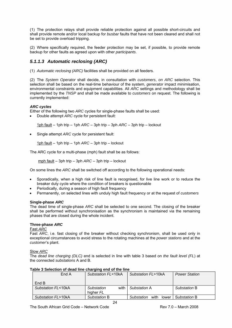
(1) The protection relays shall provide reliable protection against all possible short-circuits and shall provide remote and/or local backup for busbar faults that have not been cleared and shall not be set to provide overload tripping. (2) Where specifically required, the feeder protection may be set, if possible, to provide remote backup for other faults as agreed upon with other participants. 5.1.1.3 Automatic reclosing (ARC) (1) Automatic reclosing (ARC) facilities shall be provided on all feeders. (2) The System Operator shall decide, in consultation with customers, on ARC selection. This selection shall be based on the real-time behaviour of the system, generator impact minimisation, environmental constraints and equipment capabilities. All ARC settings and methodology shall be implemented by the TNSP and shall be made available to customers on request. The following is currently implemented: ARC cycles Either of the following two ARC cycles for single-phase faults shall be used: • Double attempt ARC cycle for persistent fault:
1ph fault – 1ph trip – 1ph ARC – 3ph trip – 3ph ARC – 3ph trip – lockout
• Single attempt ARC cycle for persistent fault: 1ph fault – 1ph trip – 1ph ARC – 3ph trip – lockout
The ARC cycle for a multi-phase (mph) fault shall be as follows:
mph fault – 3ph trip – 3ph ARC – 3ph trip – lockout On some lines the ARC shall be switched off according to the following operational needs: • Sporadically, when a high risk of line fault is recognised, for live line work or to reduce the
breaker duty cycle where the condition of breakers is questionable • Periodically, during a season of high fault frequency • Permanently, on selected lines with unduly high fault frequency or at the request of customers Single-phase ARC The dead time of single-phase ARC shall be selected to one second. The closing of the breaker shall be performed without synchronisation as the synchronism is maintained via the remaining phases that are closed during the whole incident. Three-phase ARC Fast ARC Fast ARC, i.e. fast closing of the breaker without checking synchronism, shall be used only in exceptional circumstances to avoid stress to the rotating machines at the power stations and at the customer’s plant. Slow ARC The dead line charging (DLC) end is selected in line with table 3 based on the fault level (FL) at the connected substations A and B. Table 3 Selection of dead line charging end of the line
End A End B
Substation FL<10kA Substation FL>10kA Power Station
Substation FL<10kA Substation with higher FL
Substation A Substation B
Substation FL>10kA Substation B Substation with lower Substation B

25 The South African Grid Code – Network Code Rev 7.0 – March 2008
FL Power Station Substation A Substation A Power station with
lower FL In most applications the dead time of slow ARC is set to three seconds at the DLC end of the line. At the synchronising end of the line the ARC dead time is usually set to four seconds. The close command will be issued only after synch-check is completed. This may take up to two seconds if synchronising relays are not equipped with direct slip frequency measurement. The breaker may take longer to close if its mechanism is not ready to close after initial operation at the time when the close command is issued. On the line between two power stations the dead time at the DLC end should be extended to 25 seconds to allow units’ rotor oscillations to stabilise. The dead time on the synchronising end is then accordingly extended to 30 seconds The synchronising relays shall be installed at both ends of the line to enable flexibility in ARC cycles and during restoration. 5.1.1.4 Power swing blocking (1) The NTC shall ensure that all unwanted operations of distance relays during power swing conditions are blocked on the TS. The TNSP shall ensure that all new distance relays on the TS shall be equipped with power swing blocking (PSB) facilities. 5.1.2 Feeder protection: 132kV and below, at TNSP substations 5.1.2.1 Design standards (1) The TNSP shall ensure that these feeders shall be protected by a single or dual main protection system, incorporating either distance or differential protection. The single main protection system shall have a separate backup protection system for both phase–to-phase and phase-to-earth faults. The criteria used to select between a dual main protection systems versus a single main with back-up will be based on the system and customer requirements (2) The protection shall be equipped with automatic reclosing. Synchronising relays shall be provided on feeders that operate in “ring supplies” and are equipped with line voltage transformers. 5.1.2.2 Protection settings (1) Protection relays shall provide reliable protection against all possible short-circuits, shall provide remote and/or local backup for uncleared busbar faults and shall not be set to provide overload tripping where measurements and alarms are provided on the SCADA system. In isolated applications where the SCADA system is not available, overload tripping shall be provided. Where overload conditions are alarmed at control centres, it is the control centre’s responsibility to reduce load to an acceptable level as quickly as possible. 5.1.2.3 Automatic reclosing (1) The customer shall determine ARC requirements. The System Operator may specify additional ARC requirements for system security reasons, which could extend beyond the TNSP substations. 5.1.3 Teleprotection requirements (1) New distance protection systems shall be equipped with teleprotection facilities to enhance the speed of operation.

26 The South African Grid Code – Network Code Rev 7.0 – March 2008
5.1.4 Transformer and reactor protection (1) The standard schemes for transformer protection comprise a number of systems, each designed to provide the requisite degree of protection for the following fault conditions: Faults within the tank Faults on transformer connections Overheating Faults external to the transformer (2) The TNSP shall consider the application and where necessary implement the following relays in the design of the protection system: Transformer IDMT E/F The MV (transformer secondary voltage) E/F protection shall discriminate with the feeder B/U E/F protection for feeder faults. Transformer HV/MV IDMT O/C The System Operator requires that the IDMT O/C does not operate for twice transformer full load. Overloading of the transformer is catered for by the winding and oil temperature protection. Transformer HV/MV instantaneous O/C This backup protection is to cater for flash-overs external to the transformer on the HV side or MV side and should operate for minimum fault conditions (possibly also for an E/F condition). However, the overriding requirement is that it shall not operate for through faults or for magnetising inrush current. Transformer LV (tertiary) IDMT/instantaneous O/C This protection is to operate for external faults between the main delta winding of the transformer and the auxiliary transformer, but not for faults on the secondary side of the auxiliary transformer. The auxiliary transformer is protected by Buchholz and temperature protection. Transformer current differential protection This is the main transformer protection for E/F and phase-to-phase faults. Maximum sensitivity is required, while ensuring no incorrect operation for load, for through fault conditions or for magnetising inrush current, with its attendant decaying offset. Transformer high impedance restricted E/F This protection is an additional protection for the transformer differential relay to cater for earth faults close to the star point of the transformer winding, where phase–to-phase faults are most unlikely to occur. Transformer thermal overload Winding temperature and oil temperature relays, supplied by the manufacturer, are used to prevent transformer damage or lifetime reduction owing to excessive loading for the ambient temperature or during failure of the cooling system. 5.1.5 Transmission busbar protection (1) Busbars shall be protected by current differential protection (buszone) set to be as sensitive as possible for the “in-zone faults” and to maintain stability for any faults outside the protected zone, even with fully saturated CT's. (2) At power stations, overlapped bus zones shall be retained to ensure the fastest possible clearance of busbar faults. 5.1.6 Transmission bus coupler and bus section protection (1) Bus coupler and bus section panels shall be equipped with O/C and E/F protection.
27 The South African Grid Code – Network Code Rev 7.0 – March 2008
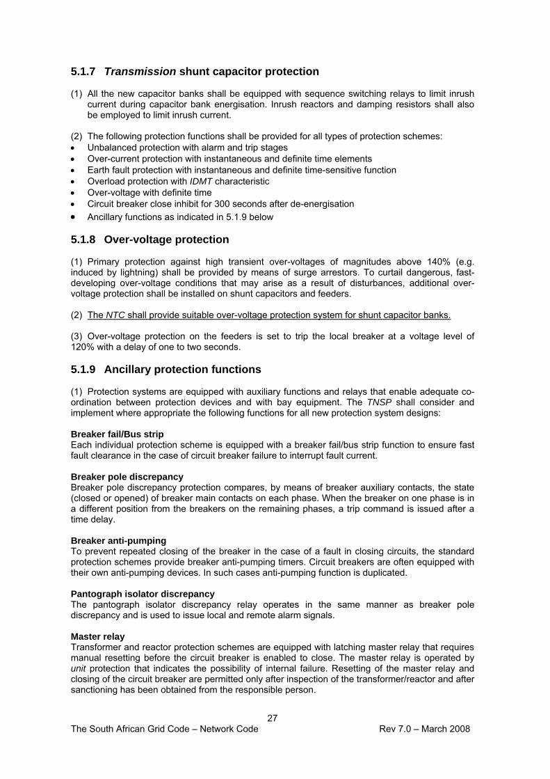
5.1.7 Transmission shunt capacitor protection (1) All the new capacitor banks shall be equipped with sequence switching relays to limit inrush
current during capacitor bank energisation. Inrush reactors and damping resistors shall also be employed to limit inrush current.
(2) The following protection functions shall be provided for all types of protection schemes: • Unbalanced protection with alarm and trip stages • Over-current protection with instantaneous and definite time elements • Earth fault protection with instantaneous and definite time-sensitive function • Overload protection with IDMT characteristic • Over-voltage with definite time • Circuit breaker close inhibit for 300 seconds after de-energisation • Ancillary functions as indicated in 5.1.9 below 5.1.8 Over-voltage protection (1) Primary protection against high transient over-voltages of magnitudes above 140% (e.g. induced by lightning) shall be provided by means of surge arrestors. To curtail dangerous, fast-developing over-voltage conditions that may arise as a result of disturbances, additional over-voltage protection shall be installed on shunt capacitors and feeders. (2) The NTC shall provide suitable over-voltage protection system for shunt capacitor banks. (3) Over-voltage protection on the feeders is set to trip the local breaker at a voltage level of 120% with a delay of one to two seconds. 5.1.9 Ancillary protection functions (1) Protection systems are equipped with auxiliary functions and relays that enable adequate co-ordination between protection devices and with bay equipment. The TNSP shall consider and implement where appropriate the following functions for all new protection system designs: Breaker fail/Bus strip Each individual protection scheme is equipped with a breaker fail/bus strip function to ensure fast fault clearance in the case of circuit breaker failure to interrupt fault current. Breaker pole discrepancy Breaker pole discrepancy protection compares, by means of breaker auxiliary contacts, the state (closed or opened) of breaker main contacts on each phase. When the breaker on one phase is in a different position from the breakers on the remaining phases, a trip command is issued after a time delay. Breaker anti-pumping To prevent repeated closing of the breaker in the case of a fault in closing circuits, the standard protection schemes provide breaker anti-pumping timers. Circuit breakers are often equipped with their own anti-pumping devices. In such cases anti-pumping function is duplicated. Pantograph isolator discrepancy The pantograph isolator discrepancy relay operates in the same manner as breaker pole discrepancy and is used to issue local and remote alarm signals. Master relay Transformer and reactor protection schemes are equipped with latching master relay that requires manual resetting before the circuit breaker is enabled to close. The master relay is operated by unit protection that indicates the possibility of internal failure. Resetting of the master relay and closing of the circuit breaker are permitted only after inspection of the transformer/reactor and after sanctioning has been obtained from the responsible person.

28 The South African Grid Code – Network Code Rev 7.0 – March 2008
5.2 System protection requirements 5.2.1 Under-frequency load shedding (1) The actions taken on the power system during an under-frequency condition are set out in section 9 of the System Operation Code. (2) Under-frequency load shedding relays shall be installed as determined by the System Operator in consultation with the customers. Where such equipment is installed in customer plant, this shall be done in agreement with the customer. The respective distributor or TNSP shall pay for the installation and maintenance of these relays. (3) Under-frequency schemes shall be tested every two years. Distributors and end-use customers shall submit to the System Operator a copy of the written report on each such test, within a month of the test being done, in the format specified in section 5.3 of the Information Exchange Code. The testing shall be done by isolating all actual tripping circuits, injecting a frequency to simulate a frequency collapse and checking all related functionality. 5.2.2 Out-of-step tripping (1) The purpose of the out-of-step tripping protection is to separate the IPS in a situation where a loss of synchronous operation takes place between a unit or units and the main power system. In such a situation system separation is desirable to remedy the situation. Once the islanded system has been stabilised, it can be reconnected to the main system. (2) The System Operator shall determine and specify the out-of step tripping functionality to be installed at selected locations on the TS by the TNSP. 5.2.3 Under-voltage load shedding (1) Under-voltage load shedding protection schemes are used to prevent loss of steady-state stability under conditions of large local shortages of reactive power (voltage collapse). Automatic load shedding of suitable loads is carried out to arrest the slide. (2) The System Operator shall determine and specify the under-voltage load shedding functionality to be installed at selected locations on the TS by the TNSP. 5.2.4 Sub-synchronous resonance protection (1) The sub-synchronous resonance (SSR) condition may arise on the IPS where a unit is connected to the IPS through long series compensated transmission lines. The potential for unstable interaction is related to system topology and is greater where higher degrees of compensation and if larger thermal units are employed. The SSR condition is addressed through either protection or mitigation. In the case of protection, a suitable relay shall be deployed as part of the unit protection that will lead to the unit disconnecting on detection of the SSR condition. The protection does not reduce or eliminate the torsional vibration, but rather detects it and acts to remove the condition leading to the resonance. Mitigation, on the other hand, acts to reduce or eliminate the resonant condition. Mitigation is needed only where it is desirable or essential to continue operation when the power system is at or near a resonant condition. (2) New generators shall liase with the NTC regarding SSR protection studies. Least-cost solutions shall be determined by the NTC in accordance with section 7 and implemented by the relevant asset owner. (3) Any dispute as to the allocation of costs for the equipment identified in clause 2 above, shall be decided in terms of the dispute resolution mechanism in the Governance Code. 5.3 Protection system performance monitoring

29 The South African Grid Code – Network Code Rev 7.0 – March 2008
(1) To maintain a high level of protection performance and long-term sustainability, the TNSP shall monitor protection performance on the TS. The TNSP shall ensure that the protection performance is adequate at all times. (2) Each protection operation shall be investigated by the TNSP for its correctness based on available information. The TNSP shall provide customers affected by a protection operation with a report when requested to do so. 6. Nomenclature (1) All safety terminology shall be determined by the NTC in compliance with the Occupational Health and Safety Act. (2) Engineering drawings relating to connecting equipment shall use the standard NTC symbol set and layout conventions as defined in Appendix 1. 7. TS planning and development (1) This section specifies the criteria and procedures to be applied by the NTC in the planning and development of the TS. It furthermore provides for accountability for TS planning and development and sets the required standards and targets. It also specifies the reciprocal obligations and interactions between participants. (2) The TS shall be developed in accordance with the prevailing NERSA regulatory framework, as being implemented from time to time. (3) The development of the TS may occur for a number of reasons, including but not limited to • changes to customer requirements or networks • the introduction of a new transmission substation or point of connection or the modification of
an existing connection between a customer and the TS • the cumulative effect of a number of developments as referred to above • the need to reconfigure, decommission or optimise parts of the existing network. (4) The time required for the planning and development of the TS will depend on the type and extent of the necessary reinforcement and/or extension work, the need or otherwise for statutory planning consent, the associated possibility of the need for public participation and the degree of complexity involved in undertaking the new work while maintaining satisfactory security and quality of supply on the existing TS. 7.1 Planning process (1) The NTC shall follow a planning process divided into major activities as follows: • Identification of the problem • Formulation of alternative options to meet this need • Study of these options to ensure compliance with agreed technical limits and justifiable
reliability and quality of supply standards • Costing of these options on the basis of approved procedures • Determination of the preferred option • Building of a business case for the preferred option using the approved justification criteria • Request for approval of the preferred option and initiation of execution. 7.2 Identification of the need for TS development (1) The NTC shall source relevant data from the National Integrated Resource Plan, the National Integrated Energy Plan, specific customer information, system performance statistics, TS load forecast, and government and customer development plans to establish the need for network strengthening.

30 The South African Grid Code – Network Code Rev 7.0 – March 2008
(2) The needs shall be determined through the modelling of the TS over a ten-year term, utilising reasonable load and generation forecasts and equipment performance scenarios. Studies for purposes of determining connection charges payable by customers may cover a shorter period if appropriate. (3) The NTC shall annually conduct a planning review with parties to co-ordinate TS and distributor network development needs. 7.3 Forecasting the demand (1) The NTC shall annually produce a TS demand forecast for the next ten years by end August of each year. (2) The TS demand forecast shall be determined for each point of supply. Generation and import capacity plans shall be used to obtain the annual generation patterns. (3) To forecast the maximum demand (MW) for each transmission substation, the NTC shall use distributor and end-use customer load forecasts. (4) The load forecast shall be adjusted at various levels (making use of diversity factors determined from measurements and calculations) to bring it into line with the higher-level data. (5) All distributors and end-use customers (or their retailer) shall supply their ten-year-ahead load forecast data to the NTC as detailed in the Information Exchange Code annually, by the end of July. All customers shall inform the NTC of any changes in excess of 50 MW to this forecast when this information becomes available.
7.4 TS development plan (1) The NTC shall annually publish a five-year-ahead TS development plan by end April, indicating the major capital investments planned (but not yet necessarily approved). The plan shall include at least • the acquisition of servitudes for strategic purposes • a list of planned investments including costs • diagrams displaying the planned changes to the TS • an indication of the impact on customers in terms of service quality and cost • any other information as specified by the NERSA from time to time. (2) The TS development plan shall be based on all customer requests received at that time, as well as NTC initiated projects based on load forecasts and changes in generation. (3) The NTC shall engage in a consultative process with customers and the NERSA on the TS development plan. The consultation process shall include • an annual public forum to disseminate the intended TS development plan • regular interfacing and joint planning with participants regarding TS development. (4) Disputes arising from the above process shall be decided in terms of the dispute resolution mechanism in the Governance Code. (5) The NTC shall provide a five-year statement of opportunities to render ancillary services for the mitigation of network constraints. (6) The NTC shall also provide other IPS development plans as defined in the licence and/or
market rules. 7.5 Development investigation reports
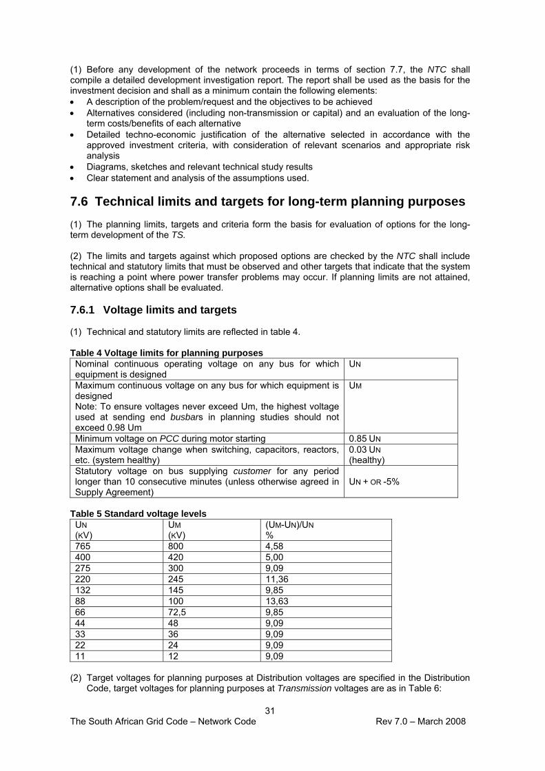
31 The South African Grid Code – Network Code Rev 7.0 – March 2008
(1) Before any development of the network proceeds in terms of section 7.7, the NTC shall compile a detailed development investigation report. The report shall be used as the basis for the investment decision and shall as a minimum contain the following elements: • A description of the problem/request and the objectives to be achieved • Alternatives considered (including non-transmission or capital) and an evaluation of the long-
term costs/benefits of each alternative • Detailed techno-economic justification of the alternative selected in accordance with the
approved investment criteria, with consideration of relevant scenarios and appropriate risk analysis
• Diagrams, sketches and relevant technical study results • Clear statement and analysis of the assumptions used. 7.6 Technical limits and targets for long-term planning purposes (1) The planning limits, targets and criteria form the basis for evaluation of options for the long-term development of the TS. (2) The limits and targets against which proposed options are checked by the NTC shall include technical and statutory limits that must be observed and other targets that indicate that the system is reaching a point where power transfer problems may occur. If planning limits are not attained, alternative options shall be evaluated. 7.6.1 Voltage limits and targets (1) Technical and statutory limits are reflected in table 4. Table 4 Voltage limits for planning purposes Nominal continuous operating voltage on any bus for which equipment is designed
UN
Maximum continuous voltage on any bus for which equipment is designed Note: To ensure voltages never exceed Um, the highest voltage used at sending end busbars in planning studies should not exceed 0.98 Um
UM
Minimum voltage on PCC during motor starting 0.85 UN Maximum voltage change when switching, capacitors, reactors, etc. (system healthy)
0.03 UN (healthy)
Statutory voltage on bus supplying customer for any period longer than 10 consecutive minutes (unless otherwise agreed in Supply Agreement)
UN + OR -5%
Table 5 Standard voltage levels UN (KV)
UM (KV)
(UM-UN)/UN %
765 800 4,58 400 420 5,00 275 300 9,09 220 245 11,36 132 145 9,85 88 100 13,63 66 72,5 9,85 44 48 9,09 33 36 9,09 22 24 9,09 11 12 9,09
(2) Target voltages for planning purposes at Distribution voltages are specified in the Distribution
Code, target voltages for planning purposes at Transmission voltages are as in Table 6:

32 The South African Grid Code – Network Code Rev 7.0 – March 2008
Table 6 Target voltages for planning purposes at Transmission voltages Minimum steady state voltage at bus supplying customer load unless otherwise specified in the customer’s supply agreement
0.95 UN
Minimum and maximum steady state voltage on any controlled bus, unless otherwise specified in the customer supply agreement:
system healthy: after designed contingency (before control actions): (after control actions):
0.95 – 1.05UN 0.90 UN – 0.98 UM 0.95 – 1.05 UN
Maximum steady state voltage at bus supplying customer load unless otherwise specified in the customer supply agreement
1.05 UN
Maximum harmonic voltage caused by customer at PCC: Individual harmonic: total (square root of sum of squares):
0.01 UN 0.03 UN
Maximum negative sequence voltage caused by customer at PCC:Continuous single-phase load connected phase-to-phase: Multiple, continuously varying, single-phase loads:
0.01 UN 0.015 UN
Harmonic voltage limits: AS DEFINED IN NRS048
Maximum voltage change owing to load varying N times per hour: (4.5 LOG10N)% OF UN
Maximum voltage decrease for a 5% (MW) load increase at receiving end of system (without adjustment):
0.05 UN
7.6.2 Other targets for long-term planning purposes
7.6.2.1 Transmission lines (1) The NTC shall determine thermal ratings of standard transmission lines and update these from time to time. The thermal ratings shall be used as an initial check of line overloading. If the limits are exceeded, the situation shall be investigated, as it may be possible to defer strengthening depending on the actual line and on local conditions. 7.6.2.2 Transformers (1) Standard transformer ratings shall be determined and updated from time to time using IEC specifications. The permissible overload of a specific transformer depends on load cycle, ambient temperature and other factors. If target loads are exceeded, the specific situation shall be assessed, as it may be possible to defer adding extra transformers. 7.6.2.3 Series capacitors (1) The maximum steady state current should not exceed the rated current of the series capacitor. The internationally accepted standard’s cyclic overload capabilities are for operational use only, to allow the System Operator time to reduce loading to within the rated current without damaging the series capacitor. 7.6.2.4 Shunt reactive compensation (1) Shunt capacitors shall be able to operate at 30% above their nominal rated current at Un to allow for harmonics and voltages up to Um. 7.6.2.5 Circuit breakers (1) The TNSP shall specify and install circuit breakers that meet system fault levels and other conditions considered important for the safe and secure operation of the TS. Ratings are to be according to international circuit breaker standards such as IEC.

33 The South African Grid Code – Network Code Rev 7.0 – March 2008
7.6.3 Reliability criteria for long-term planning purposes (1) The NTC shall formulate long-term plans for development of the TS on the basis of the justifiable redundancy. With one line or transformer or reactive compensation device out of service (n-1), it shall be possible to supply the entire load under all credible system operating conditions. (2) Investment in the TS to satisfy the minimum (n-1) redundancy requirement shall be on a deterministic basis, with no financial justification required. (3) An unfirm transmission infeed to an underlying distribution network is acceptable, as long as the underlying distribution network can supply the entire load without load shedding or load curtailment and without violating the technical planning limits on either the transmission or Distribution systems on loss of the transmission infeed. (4) A system cannot be made 100% reliable, as planned and forced outages of components will occur and multiple outages are always possible, despite having a very low probability of occurrence. (5) The NTC shall in planning the TS minimise as far as practicable the risk of common cause failure of two or more items of plant (e.g. loss of two or more lines in a common servitude or on a double circuit or multicircuit structure), and insofar as such risk is unavoidable, shall take reasonable measures to mitigate such risk. (6) Additional equipment shall be provided if it can be justified to be included in the rate base in terms of the least economic cost and/or cost reduction investment criteria (sections 7.7.1 and 7.7.2) or the cost is recoverable from a customer or group of customers in accordance with the Transmission Tariff Code or section 7.9. 7.6.4 Contingency criteria for long-term planning purposes (1) A system meeting the n-1 (or n-2) contingency criterion must comply with all relevant limits outlined in section 7.6.1 (voltage limits) and the applicable current limits, under all credible system conditions. (2) For contingencies under various loading conditions it shall be assumed that appropriate, normally used generating plant is in service to meet the load and provide spinning reserve. For the more probable n-1 network contingency, the most unfavourable generation pattern within these limitations shall be assumed, while for the less probable n-2 network contingency an average pattern shall be used. More details of load and generation assumptions for load flow studies are given in section 7.6.5. (3) The generation assumptions for the n-1 and n-2 network contingencies do not affect the final justification to proceed with investments, but merely define what is meant by the statement that the system has been designed to meet an n-1 or n-2 contingency. 7.6.5 Integration of power stations (1) When the integration of power stations is planned, the following network redundancy criteria
shall apply: Power stations of less than 1 000 MW • With all connecting lines in service, it shall be possible to transmit the total output of the
power station to the system for any system load condition. If the local area depends on the power station for voltage support, the connection shall be made with a minimum of two lines.
• Transient stability shall be maintained following a successfully cleared single-phase fault. • If only a single line is used, it shall have the capability of being switched to alternative busbars
and be able to go onto bypass at each end of the line. Power stations of more than 1 000 MW

34 The South African Grid Code – Network Code Rev 7.0 – March 2008
• With one connecting line out of service (n-1), it shall be possible to transmit the total output of the power station to the system for any system load condition.
• With the two most onerous line outages (n-2), it shall be possible to transmit the total output of the power station less its smallest unit to the system.
• Smallest unit installed at the power station shall only include units that are directly connected to the transmission system and are centrally dispatched.
(2) Transient stability shall be retained for the following conditions: • A three-phase line or busbar fault, cleared in normal protection times, with the system healthy
and the most onerous power station loading condition; or • A single-phase fault cleared in “bus strip” times, with the system healthy and the most
onerous power station loading condition; or • A single-phase fault, cleared in normal protection times, with any one line out of service and
the power station loaded to average availability. (3) The cost of ensuring transient stability shall be carried by the generator if the optimum solution, as determined by the NTC, results in unit or power station equipment being installed. In other cases, the TNSP shall bear the costs and recover these as per the approved tariff methodology. (4) Busbar layouts shall allow for selection to alternative busbars. In addition, feeders must have the ability to go onto bypass. (5) The busbar layout shall ensure that not more than 1 000 MW of generation is lost as a result of a single contingency. (6) To enable the NTC to successfully integrate new power stations, detailed information is required per unit and power station, as described in the Information Exchange Code. (7) When the integration of a nuclear facility or off-site power supply to a nuclear facility is planned, the levels of redundancy and/or reliability of the TS and off-site power supply requirements specified in its nuclear operating license or by the National Nuclear Regulator shall apply. 7.7 Criteria for network investments (1) The NTC shall invest in the TS when the required development meets the technical and investment criteria specified in this section, or if the investment is in response to a customer request for transmission service and the cost is recoverable from the customer or group of customers concerned in accordance with the NERSA approved connection charges guidelines. (2) The NTC shall communicate all impacts timeously such that provision can be made for budgeting and implementation of related changes at the customer installation. (3) Any one of the investment criteria below, each applicable under different circumstances, can be applied. (4) Calculations will assume a typical project life expectancy of 25 years, except where otherwise dictated by plant life or project life expectancy. (5) The following key economic parameters shall have an NERSA-approved process of
establishment: • Discount rate • COUE • Other parameters as specified by the NERSA from time to time. 7.7.1 Least economic cost criteria (1) These criteria shall apply under the following circumstances:

35 The South African Grid Code – Network Code Rev 7.0 – March 2008
• When new customers are to be connected • When investments are made in terms of improved supply reliability and/or quality to attain the
limits or targets determined in section 7.6 • To determine and/or verify the desired level of network or equipment redundancy (2) The methodology for determining the value of load or generation in neighbouring countries shall be approved by the NERSA. (3) The methodology requires the cost of poor network services to be determined. These include
the cost of • interruptions • load shedding • network constraints • poor quality of supply (QOS). (4) The least-cost investment criterion equation to be satisfied can be expressed as follows: “Value of improved QOS to customers > cost to the service provider to provide improved QOS” – (1) (5) From this equation it is evident that if the value of the improved QOS to the customer is less than the cost to the service provider, then the service provider should not invest in the proposed project(s). The investment decision shall then be delayed such that optimised economic benefit can be derived. (6) This implies that for the criteria to be satisfied: “COUE annual value (R/kWh) x annual reduction in EENS to consumers (kWh) > annual cost to the service provider to reduce EENS (R)” - (2) (7) The reduction in EENS (expected energy not served) is calculated on a probabilistic basis based on the improvements derived from the investments. (8) The cost of unserved energy (COUE) is a function of the types of loads, the proportion of the total load contributed by each different type of load, the duration and frequency of the interruptions, the time of the day they occur, whether notice is given of the impending interruption, the indirect damage caused, the start-up costs incurred by the customers, the availability of customer backup generation and many other factors. 7.7.2 Cost reduction investments (1) Proposed expenditure that is intended to reduce service providers’ costs (e.g. shunt capacitor installations, telecommunication projects and equipment replacement that reduce costs, external telephone service expenses and maintenance costs respectively) or the cost of losses or other ancillary services should be evaluated in the following manner: • First, it is necessary to calculate the NPV of the proposed investment using the DCF
methods. This shall be done by considering all cost reductions (e.g. savings in system losses) as positive cash flows, off-setting the required capital expenditure. Once again, sensitivity analysis with respect to the amount of capital expenditure (estimated contingency amount), the AAICOG (when appropriate) and future load growth scenarios is required. As before, a resulting positive NPV indicates that the investment is justified over the expected life of the proposed new asset.
• However, a positive NPV does not always indicate the optimal timing for the investment. For this reason, the second portion of the cost reduction analysis is necessary – ascertaining whether the annual extra costs incurred by the service provider for owning (levelised) and operating the proposed asset is less than all cost reductions resulting from the new asset in the first year that it is in commission.
7.7.3 Statutory investments

36 The South African Grid Code – Network Code Rev 7.0 – March 2008
(1) This category of projects comprises investments that the service provider is legally required to make, irrespective of whether any economic benefit is likely to accrue, including the following: • Investments formally requested in terms of published government policy • Investments formally required by the National Nuclear Regulator • Projects necessary to meet environmental legislation, e.g. the construction of oil containment
dams or EIA and procurement of an uncontested Record of Decision prior to construction of a new line
• Expenditure to satisfy the requirements of the Occupational Health and Safety Act of 1993. This classification is intended to ensure the safety of operating and maintenance personnel who are exposed to possible danger when busy with activities related to electricity transmission and the safety of the general public
• Expenditure required to comply with other applicable legislation • Expenditure required to comply with court orders • Possible compulsory contractual commitments (2) The results of the least economic cost and/or cost reduction analyses should still be documented to demonstrate the financial impact on the business. 7.7.4 Strategic investments (1) This category of investments comprises discretionary investments made by the service provider to ensure the long term sustainability of the service provider, including: • Site and servitude acquisition • Expenditure, except for network expansion, required to ensure the longer term sustainability
of the service provider which cannot be justified in terms of the least economic cost and cost reduction investment criteria (sections 7.7.1 and 7.7.2) or recovered from a customer or group of customers as a connection charge in terms of the Transmission Tariff Code or section 7.9 of this code. In this case, the motivation as to why the investment is genuinely needed to ensure the longer term sustainability of the service provider must be clearly stated, and the results of the least economic cost and/or cost reduction analyses must be documented, or reasons given why such analysis is not possible or practical. These shall include purchasing of capital spares to minimise outage duration following major plant failure, purchase of specialised vehicles and equipment to transport transformers and reactors, or implementation of industry restructuring.
• Asset replacements forming part of an asset lifecycle management plan compiled in
accordance with asset management practices approved by the NERSA. • Network expansion projects which can not be justified in terms of n-1 redundancy or can not
be recovered from a customer or group of customers as a connection charge in terms of the Transmission Tariff Code or section 7.9 of this code, but will provide flexibility, and avoid network redundancy in the future.
• Any other investments considered by the service provider to be justified as strategic on
grounds other than those covered in this section are to be submitted to the NERSA for consideration on a case by case basis prior to commitment to expenditure. The results of the least economic cost and/or cost reduction analyses should still be documented to demonstrate the financial impact on the business.
7.8 Mitigation of network constraints (1) The NTC has the obligation to resolve network constraints. (2) Network constraints (“congestion”) shall be regularly reviewed by the NTC. Economically optimal plans shall be put in place around each constraint, which may involve investment, the purchase of the constrained generation, ancillary service or other solutions.

37 The South African Grid Code – Network Code Rev 7.0 – March 2008
7.9 Special customer requirements for increased reliability (1) Should a customer require a more reliable or safer connection than the one provided for by the NTC, and the customer is willing to pay the total cost of providing the increased reliability in the form of an additional connection charge, the TNSP shall meet the requirements at the lowest overall cost. 8. Network maintenance (1) Participants shall operate and maintain the equipment owned by them. The cost of such operation and maintenance shall be borne by the respective participants unless such equipment is proved to have been damaged by a negligent act or omission of a participant other than the owner, its agents or employees, in which case the responsible participant shall be liable for the costs of repairing such damage. (2) Participants shall monitor the performance of their plant and take appropriate corrective action where deteriorating trends are detected. (3) Maintenance scheduling shall be done in accordance with the System Operation Code. (4) The TNSP shall agree in writing with its customers, details of any special maintenance requirements as well as maintenance co-ordination requirements per transmission substation. The TNSP shall provide customers with details of its maintenance plans and practices upon request, if these affect the quality of the connection.

38 The South African Grid Code – Network Code Rev 7.0 – March 2008
APPENDIX 1: Electrical drawing symbols set and layout conventions NRS 002 “Graphical Symbols for Electrical Diagrams” shall be used as the standard for electrical drawings, unless otherwise agreed between a service provider and a customer.

39 The South African Grid Code – Network Code Rev 7.0 – March 2008
APPENDIX 2: Surveying, monitoring and testing for generators A2.1 Introduction
This section specifies the procedures to be followed in carrying out surveying, monitoring or testing to confirm the • compliance by generators with the Grid Code • provision by generators of ancillary services that they are required or have agreed to provide. A2.2 Ongoing monitoring of a unit’s performance Generators shall monitor each of their units during normal service to confirm ongoing compliance with the applicable parts of this code. Any material deviations detected must be reported to the System Operator within five working days. Generators shall keep records relating to the compliance by each of their units with each section of this code applicable to that unit, setting out such information as the System Operator or TNSP reasonably requires for assessing power system performance (including actual unit performance during abnormal conditions).
Within one month after the end of June and December, generators shall provide the System Operator with a report detailing the compliance or non-compliance in any material respect by each of their units with every section of the Network Code during the previous six-month period. The template for this appears as Appendix 3 in the Information Exchange Code.
A2.3 Procedures


The South African Grid Code – Network Code Rev 7.0 – March 2008
41
A2.3.1 Unit protection system GCR1
Parameter Reference
Protection function and setting integrity study
3.1.1 APPLICABILITY AND FREQUENCY Prototype study: All new power stations coming on line or power stations at which major refurbishment or upgrades of protection systems have taken place. Routine review: All generators to confirm compliance every six years. PURPOSE To ensure that the relevant protection functions in the power station are co-ordinated and aligned with the system requirements. PROCEDURE Prototype: 1. Establish the system protection function and associated trip level requirements from the System
Operator. 2. Derive protection functions and settings that match the power station plant, transmission plant and
system requirements. 3. Confirm the stability of each protection function for all relevant system conditions. 4. Document the details of the trip levels and stability calculations for each protection function. 5. Convert protection tripping levels for each protection function into a per unit base. 6. Consolidate all settings in a per unit base for all protection functions in one document. 7. Derive actual relay dial setting details and document the relay setting sheet for all protection functions. 8. Document the position of each protection function on one single line diagram of the generating unit and
associated connections. 9. Document the tripping functions for each tripping function on one tripping logic diagram. 10. Consolidate detail setting calculations, per unit setting sheets, relay setting sheets, plant base
information on which the settings are based, tripping logic diagram, protection function single line diagram and relevant protection relay manufacturers’ information into one document.
11. Submit to the System Operator for its acceptance and update. 12. Provide the System Operator with one original master copy and one working copy. Review: 1. Review Items 1 to 10 above. 2. Submit to the System Operator for its acceptance and update. 3. Provide the System Operator with one original master copy and one working copy. ACCEPTANCE CRITERIA All protection functions are set to meet the necessary protection requirements of the transmission and power station plant with a minimal margin, optimal fault clearing times and maximum plant availability.

The South African Grid Code – Network Code Rev 7.0 – March 2008
42
Submit a report to the System Operator one month after commissioning for a prototype study or six-yearly for routine tests.
Parameter Reference Protection integrity tests
3.1.1. APPLICABILITY Prototype test: All new power stations coming on line and all other power stations after major works of refurbishment of protection or related plant. Also, when modification or work has been done to the protection, items 2 to 5 must be carried out. This may, however, be limited to the areas worked on or modified. Routine test:/Reviews: All units on: item 1 below: Review and confirm every 6 years item 2, and 3 below: at least every 12 years. . PURPOSE To confirm that the protection has been wired and functions according to the specifications. PROCEDURE 1. Apply final settings as per agreed documentation to all protection functions. 2. With the unit off load and de-energised, inject appropriate signals into every protection function and
confirm correct operation and correct calibration. Document all protection function operations. 3. Carry out trip testing of all protection functions, from origin (e.g. Buchholz relay) to all tripping output
devices (e.g. HV breaker). Document all trip test responses. 4. Apply short-circuits at all relevant protection zones and with generator at nominal speed excite generator
slowly, record currents at all relevant protection functions and confirm correct operation of all relevant protection functions. Document all readings and responses. Remove all short-circuits.
5. With the unit at nominal speed, excite unit slowly, recording voltages on all relevant protection functions. Confirm correct operation and correct calibration of all protection functions. Document all readings and

The South African Grid Code – Network Code Rev 7.0 – March 2008
43
responses.
ACCEPTANCE CRITERIA All protection functions are fully operational and operate to required levels within the relay OEM allowable tolerances. Measuring instrumentation used shall be sufficiently accurate and calibrated to a traceable standard. Submit a report to the System Operator one month after test.

The South African Grid Code – Network Code Rev 7.0 – March 2008
44
A2.3.2 Unit Islanding capability GCR2
Parameter Reference Unit islanding 3.1.2 APPLICABILITY
Prototype test: All new power stations that do not have black start capability must test one unit. The prototype test shall be done from full output for the minimum required two hours. Where population of identical units exist at a single power station without black start capability, only one unit must undergo the prototype test to prove the ability, while the other units in such a population require only routine testing. Routine test: The unit must island from at least 60% of MCR, and must be sustained for at least 20 minutes, for routine tests, without tripping of the turbine, boiler, excitation system or other systems critical to sustaining an islanding condition. The Generator will compile a report illustrating that all the key criteria were met after 20 minutes indicating that the unit stabilised, giving the assurance that the unit would have stayed stable for a minimum of 2 hours. The unit shall be re-synchronised and be loaded to normal output. Routine tests need to be repeated at least every six years or following a major outage. Continuous monitoring: A unit islanding test shall be considered to be successful where, in the day-to-day running of the plant, a real condition arises in which a generating unit is required to island, and the islanding takes place successfully, and the islanding condition is sustained as specified under Acceptance Criteria below or is called to synchronise and completes the synchronisation successfully. PURPOSE To confirm that a generating unit that has specified it is able and/or contracted to provide an islanding service complies with the requirements. Unit islanding is the ability of a generating unit suddenly to disconnect from the TS by opening the HV breaker and to control all the necessary critical parameters automatically to a sufficient degree to maintain the turbine generator at speed and excited and supplying its own auxiliary load. PROCEDURE • The unit shall run at steady state conditions above 60% full load. • All protection and control systems in normal operating conditions. • No special modifications to the plant for the purpose of the test are allowed, except the installation of
monitoring equipment. • The unit supplies all its own auxiliary load during the test. • The unit is disconnected from the system by opening the HV circuit breaker. • All operating within the first 2 minutes has to be noted and the System Operator informed for approval. • Equipment is connected to the generating unit that records critical parameters. The following minimum
parameters are recorded:

The South African Grid Code – Network Code Rev 7.0 – March 2008
45
(a) Turbine speed (b) Alternator load (c) Alternator voltage and current (d) Exciter voltage and current (e) Unit board voltage (f) Anticipatory device position (where installed) (g) System frequency
• Unit islanding is initiated by opening the HV Breaker. ACCEPTANCE CRITERIA The turbine shall settle at or close to its nominal speed and the excitation system shall remain in automatic channel, supplying all the unit’s auxiliary load. The islanding condition shall be sustained for the agreed period. The unit shall successfully re-synchronise and load to contracted output.

The South African Grid Code – Network Code Rev 7.0 – March 2008
46
A2.3.3 Excitation system GCR3
Parameter Reference
Excitation and setting integrity study
3.1.3 APPLICABILITY AND FREQUENCY Prototype study: All new power stations coming on line or power stations at which major refurbishment or upgrades of excitation systems have taken place. Also, where localised changes or modifications are done, only affected part or parts shall be covered. Routine review: All power stations to confirm compliance every six years. PURPOSE To ensure that the excitation system in the power station is co-ordinated and aligned with the system requirements. PROCEDURE Prototype: 1. Establish the excitation system performance requirements from the System Operator. 2. Derive a suitable model for the excitation system according to IEEE 421.5 or IEC 60034.16.2. Where
necessary, non-standard models (non-IEC or IEEE) shall be created. This may require frequency response and bode plot tests on the excitation system as described in IEEE 421.2.1990.
3. Submit the model to the System Operator for their acceptance. 4. Derive excitation system settings that match the power station plant, transmission plant and system
requirements. This includes the settings of all parts of the excitation system such as the chop-over limits and levels, limiters, protection devices and alarms.
5. Confirm the stability of the excitation system for relevant excitation system operating conditions. 6. Document the details of the trip levels, stability calculations for each setting and function. 7. Convert the settings for each function into a per unit base and produce a high-level dynamic
performance model with actual settings in p.u. values. 8. Derive actual card setting details and document the relay setting sheet for all setting functions. 9. Produce a single line diagram/block diagram of all the functions in the excitation system and indicate the
signal source. 10. Document the tripping functions for each tripping on one tripping logic diagram. 11. Consolidate the detailed setting calculations, model, per unit setting sheets, relay setting sheets, plant
base information on which the settings are based, tripping logic diagram, protection function single line diagram and relevant protection relay manufacturers’ information into one document.
12. Submit to the System Operator for its acceptance and update. 13. Provide the System Operator with one original master copy and one working copy. Review:

The South African Grid Code – Network Code Rev 7.0 – March 2008
47
Review items 1 to 10 above. Submit to the System Operator for its acceptance and update. Provide the System Operator with one original master copy and one working copy update if applicable. ACCEPTANCE CRITERIA The excitation system is set to meet the necessary control requirements in an optimised manner for the performance of the transmission and power station plant. The excitation system operates stable both internally and on the network. Submit a report to the System Operator one month after commissioning for a prototype study or five to six-yearly for routine tests, within one month after expiry of the due date.

The South African Grid Code – Network Code Rev 7.0 – March 2008
48
Parameter Reference
Excitation response tests
3.1.3 APPLICABILITY Prototype test: All new power stations coming on line and all other power stations after major modifications or refurbishment of protection or related plant. Also, after localised modifications or works have been carried out to the plant that will affect this performance. Routine test: All generators to perform tests on each unit 6-yearly after a major overhaul of plant. PURPOSE To confirm that the excitation system performs as per the specifications. PROCEDURE • With the unit off line, carry out frequency scan/bode plot tests on all circuits in the excitation
system critical to the performance of the excitation system. • With the unit in the open circuit mode, carry out the large signal performance testing as
described in IEEE 421.2 of 1990. Determine time response, ceiling voltage and voltage response.
• With the unit synchronised and loaded, carry out the small signal performance tests according to IEE 421.2 of 1990. Also carry out power system stabiliser tests and determine damping with and without power system stabiliser.
• Document all responses. ACCEPTANCE CRITERIA The excitation system meets the necessary control requirements in an optimised manner for the performance of the transmission and power station plant as specified. The excitation system operates stably both internally and on the network. The power system stabilisers are set for optimised damping.

The South African Grid Code – Network Code Rev 7.0 – March 2008
49
A2.3.4 Unit reactive power capability GCR4 Parameter Reference
Reactive power capability
3.1.4 APPLICABILITY Prototype test: All new power stations coming on line and all other power stations after major modifications or refurbishment of protection or related plant. Routine test/reviews: Confirm compliance every 6 years. PURPOSE To confirm that the reactive power capability specified is met. PROCEDURE The unit will be required to regulate the voltage on the HV busbar to a set level. ACCEPTANCE CRITERIA The unit shall maintain the set voltage within ±5% of the capability registered with the System Operator for at least one hour. Submit a report to the System Operator one month after the test.

The South African Grid Code – Network Code Rev 7.0 – March 2008
50
A2.3.5 Multiple-unit trip GCR5
Parameter Reference
Multiple- unit tripping (MUT) tests, study and survey
3.1.5 APPLICABILITY Prototype tests/study/survey: • New power stations coming on line: items 1 to 5 below. • Power stations at which major modifications or changes have been implemented on plant
critical to multiple-unit tripping: applicable item(s) listed 1 to 5 below. Routine assessment: All power stations: item 5 below every 6 years Routine testing: All power stations. Review and confirm the status every 6 years, and test if required. PURPOSE To confirm that a power station is not subjected to unreasonable risk of MUT as defined in the Network Code, section 3.1.5. PROCEDURE AND ACCEPTANCE CRITERIA 1. Emergency supply isolation test: On all emergency supplies (e.g. DC supplies) common to more than one unit, isolate the supply for at least one second, with the unit running at full load under normal operating conditions. Tests are carried out on one unit at a time. Where two supplies feed one common load, isolation of one supply at a time will be sufficient. Confirm that the unit or part of the unit plant does not trip. No change in the unit output shall take place. Document results. This test does not apply to nuclear plant. 2. Disturbance on DC supply survey: On all DC supplies common to more than one unit, carry out a survey of the immunity of all devices that are part of tripping circuits, to supply voltage according to IEC specifications. All devices on DC supplies common to more than one unit that form part of tripping circuits or that can cause tripping or load reduction on a unit must comply with IEC specification. Document findings. 3. Uninterruptible power supplies (UPS) integrity testing: On all UPS’s supplying critical loads that can cause tripping of more than one unit within the time zones specified in 3.1.5, isolate the AC supply to the UPS for a period of at least one minute. Where two UPS's supply one common load, one UPS at a time can be isolated. Load

The South African Grid Code – Network Code Rev 7.0 – March 2008
51
equipment must resume normal operation. Document results. This test does not apply to nuclear plant. 4. Earth mat integrity inspection and testing: Carry out an inspection and tests on all parts of the power station earth mat that is exposed to lightning surge entry and in close proximity to circuits vulnerable to damage that will result in tripping of more than one unit within the time zones specified in 3.1.5 (e.g. chimney on fossil fuel power stations or penstock on hydro power stations) Confirm that all the earthing and bonding are in place, and measure resistances to earth at bonding points. Document findings and results. 5. MUT risk assessment: Identify all power supplies, air supplies, water supplies and other supplies/systems common to more than one unit that are likely to cause the tripping of more than one unit within the MUT categories specified in section 3.1.5. Calculate the probability of all the MUT risk areas for the power station. Document all findings, listing all risks and probabilities. No unreasonable MUT items as listed in 3.1.5 shall be present. Report to be submitted to the System Operator one month after the testing. Routine studies and survey reports to be submitted one month after expiry of the due date.

The South African Grid Code – Network Code Rev 7.0 – March 2008
52
A2.5.6 Governing system GCR6
Parameter Reference
Governing response tests
3.1.6 APPLICABILITY Prototype test: All new power stations coming on line and all other power stations after major modifications or refurbishment of protection or related plant. Routine test: All units to be monitored continuously. Additional tests may be requested by the System Operator, acting reasonably but not more than 2-yearly. PURPOSE To prove that the unit is capable of the minimum requirements for governing. PROCEDURE 1. Frequency or speed deviation to be injected on the unit for ten minutes. 2. Real power output of the unit to be measured and recorded. ACCEPTANCE CRITERIA Minimum requirements of the Grid Code are met.

The South African Grid Code – Network Code Rev 7.0 – March 2008
53
A2.3.7 Unit restart after station blackout capability GCR7
Parameter Reference
Restart after station blackout survey
3.1.7 APPLICABILITY Prototype survey: New power stations or power stations at which modifications have been carried out on plant critical to multiple-unit restarting. PURPOSE To confirm that a power station can restart units simultaneously, according to the criteria outlined in section 3.1.7, after a station blackout condition. PROCEDURE 1. Plant capacity survey: • Identify all supply systems common to two or more systems (e.g. power supplies, crude oil,
air, demin water). • Determine the quantity and supply rate required to simultaneously restart the number of
units specified in section 3.1.7. • Document critical systems, required stock, study details and findings. 2. Survey of available stock: For each of the applicable critical systems identified, document the average stock for the year, minimum stock and duration below critical stock levels.
ACCEPTANCE CRITERIA More than 95% of the time over the year, all stocks are above critical levels. Report to be submitted to the System Operator one month after commissioning. Routine survey reports to be submitted one month after expiry of the due date.
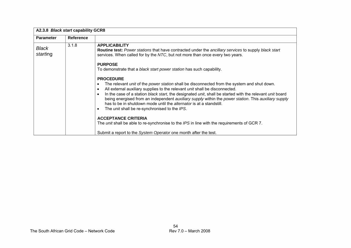
The South African Grid Code – Network Code Rev 7.0 – March 2008
54
A2.3.8 Black start capability GCR8
Parameter Reference
Black starting
3.1.8 APPLICABILITY Routine test: Power stations that have contracted under the ancillary services to supply black start services. When called for by the NTC, but not more than once every two years. PURPOSE To demonstrate that a black start power station has such capability. PROCEDURE • The relevant unit of the power station shall be disconnected from the system and shut down. • All external auxiliary supplies to the relevant unit shall be disconnected. • In the case of a station black start, the designated unit, shall be started with the relevant unit board
being energised from an independent auxiliary supply within the power station. This auxiliary supply has to be in shutdown mode until the alternator is at a standstill.
• The unit shall be re-synchronised to the IPS. ACCEPTANCE CRITERIA The unit shall be able to re-synchronise to the IPS in line with the requirements of GCR 7. Submit a report to the System Operator one month after the test.

The South African Grid Code – Network Code Rev 7.0 – March 2008
55
A2.3.9 External supply disturbance withstand capability GCR9 Parameter Reference Voltage and frequency deviation
3.1.9 APPLICABILITY Prototype survey/test: New power stations coming on line or power stations in which major modifications have been made to plant that may be critical to system supply frequency or voltage magnitude deviations: item 2 for plants using dip proofing inverters (DPI). Routine testing and survey: All power stations: review items 1 to 3 every six years. Carry out item 3 every six years. PURPOSE To confirm that the power station and its auxiliary supply loads conform to the requirements of supply frequency and voltage magnitude deviations as specified in section 3.1.9. SCOPE OF PLANT OR SYSTEMS Critical plant: Equipment or systems that are likely to cause tripping of a unit or parts of a unit or that are likely to cause a multiple-unit trip (MUT). PROCEDURE AND ACCEPTANCE CRITERIA 1. Frequency deviation survey: Carry out a survey on the capability of critical plant confirming that it will resume normal operation for frequency deviations as defined in section 3.1.6. A unit or power station shall not trip or unduly reduce load for system frequency changes in the range specified in section 3.1.6. 2. Voltage magnitude deviation survey: Carry out a survey on the capability of critical plant confirming that it will resume normal operation for voltage deviations as defined in section 3.1.7. Document findings. Also consider protection and other tripping functions on critical plant. Document all findings. A unit or power station must not trip or unduly reduce load for system voltage changes in the range specified in section 3.1.7. 3. Dip proofing inverter (DPI) integrity testing: DPIs or / and any other equipment must be tested according to the OEM requirements.
The South African Grid Code – Network Code Rev 7.0 – March 2008
56
Document all results. Report to be submitted to the System Operator one month after the testing. Routine studies and survey reports to be submitted one month after expiry of the due date.

The South African Grid Code – Network Code March 2008
57
APPENDIX 3: Transmission service application form CUSTOMER'S APPLICATION FORM
Note: Where indicated, shaded areas are for completion by the Service Provider. Please provide any additional detail in the areas designated for notes.
Customer Contact Person 1 Title: Customer Contact Person 1 Initials, Surname and Job
Title: Customer's preferred form of address
Customer Contact Person 2 Title: Customer Contact Person 2 Initials, Surname and Job Title:
Customer's preferred form of address
Company Name: As per Company or Closed Corporation registration document issued in Pretoria
Co/CC Reg No: Issued by Registrar of Companies or Closed Corporations in Pretoria
Person 1 Telephone 1: Person 1 Tele Ext: Customer's contact no Dialling code Tele number
Person 1 Telephone 2/Cell: Person 1 Fax: Alternative contact no Dialling code Tele number Dialling code Fax/Telephone number
Person 2 Telephone 1: Person 2 Tele Ext: Customer's contact no Dialling code Tele number
Person 2 Telephone 2/Cell: Person 2 Fax: Alternative contact no Dialling code Tele cumber Dialling code Fax/Telephone number
Person 1 e-mail Address: Person 2 e-mail Address:
Customer's Physical Address: Code
Customer's personal physical location
Postal Address: Code
Customer's preferred postal contact address
Physical connection to the Transmission System required? (Y/N): If not, indicate nature of business (e.g. trader, retailer, etc.):
Type of quote required (please tick):
Feasibility: Firm:
Notes:

The South African Grid Code – Network Code March 2008
58
Additional customer information
The following fields will be completed by the Service Provider
Customer ID (G) Customer Type Existing Customer:
Transmission-generated unique customer number Indicate individual/company/partnership/other
Parent Customer ID Credit Indicator
Indicates if customer is subsidiary to existing customer Indicate if other account(s) outstanding
Application Date: Connection Voltage
(kV): MVA:
Customer's initial application date ccyymmdd Indicate Capacity of Connection Required
Requested Completion Date: Estimated Monthly Consumption/Generation:
MWh
When customer wants supply available ccyy mmdd Customer's projected usage/generation for this POS
Temporary Connection: Owner or Tenant:
If short term: period (months) for which connection required Customer owns/rents property for this application
POS/Physical Connection Address:
Longitude: Latitude: Full description of the property/title deed where supply is required: street addr, lot no, etc. No postal addresses
Usage Category (Please tick): Industrial: Commercial: Distribution: Generation: International: Other (please specify):
Nearest Existing Transmission System Connection:
Transmission substation closest to POS
Other Transmission System Connections: Does customer have other transmission connections/points of supply?
Standard or Enhanced Reliability Connection:
Special Instructions:
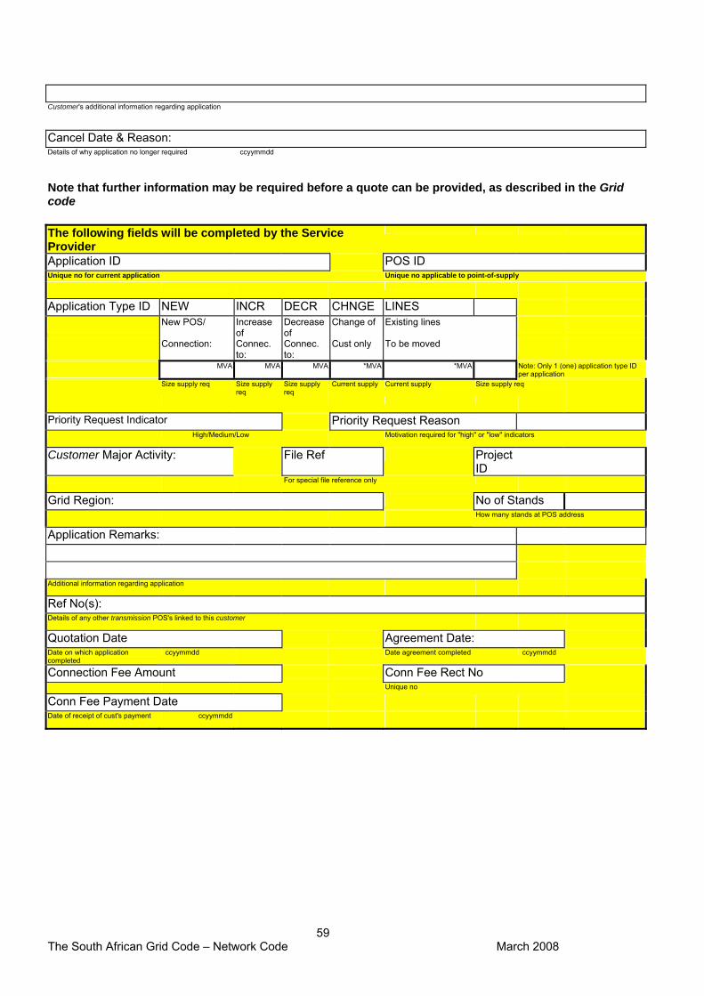
The South African Grid Code – Network Code March 2008
59
Customer's additional information regarding application
Cancel Date & Reason: Details of why application no longer required ccyymmdd
Note that further information may be required before a quote can be provided, as described in the Grid code
The following fields will be completed by the Service Provider
Application ID POS ID Unique no for current application Unique no applicable to point-of-supply
Application Type ID NEW INCR DECR CHNGE LINES
New POS/ Increase of
Decrease of
Change of Existing lines Connection: Connec.
to: Connec. to:
Cust only To be moved MVA MVA MVA *MVA *MVA Note: Only 1 (one) application type ID
per application
Size supply req Size supply req
Size supply req
Current supply Current supply Size supply req
Priority Request Indicator Priority Request Reason
High/Medium/Low Motivation required for "high" or "low" indicators
Customer Major Activity: File Ref Project ID
For special file reference only Grid Region: No of Stands How many stands at POS address
Application Remarks:
Additional information regarding application Ref No(s): Details of any other transmission POS's linked to this customer Quotation Date Agreement Date: Date on which application completed
ccyymmdd Date agreement completed ccyymmdd
Connection Fee Amount Conn Fee Rect No Unique no
Conn Fee Payment Date Date of receipt of cust's payment ccyymmdd