content.sierraclub.org · under the south dakota air pollution control regulations pursuant to...
TRANSCRIPT
Permit #: 28.0701 -PSD Effective Date: Draft
SOUTH DAKOTA DEPARTMENT OF
ENVIRONMENT AND NATURAL RESOURCES
PREVENTION OF SIGNIFICANT DETERIORATION
AIR QUALITY PRECONSTRUCTION PERMIT
Richard C. Sweetman, Chairman
Board of Minerals and Environment

Under the South Dakota Air Pollution Control Regulations
Pursuant to Chapter 34A-1-21 of the South Dakota Codified Laws and the Air Pollution Control Regulations of the State of South Dakota and in reliance on statements made by the owner designated below, a permit to construct and operate is hereby issued by the Secretary of the Department of Environment and Natural Resources. This permit authorizes such owner to construct and operate the permitted units at the location designated below and under the listed conditions:
A. Owner
1. Company name and address Hyperion Energy Center – Hyperion Refining LLC 1350 Premier Place, 5910 N. Central Expressway Dallas, Texas 75206
2. Actual Source Location and Mailing Address if Different from Above
316th Street and 474th Avenue Union County, South Dakota
3. Permit Contact Colin Campbell, Project Manager (919) 845-1422
4. Facility Contact
5. Responsible Official
Preston Phillips, Vice President (214) 750-4336
i

B. Type of Operation A 400,000 barrel per day greenfield petroleum refinery and an integrated gasification combined cycle power plant.
ii
TABLE OF CONTENTS
Page
iii
1.0 STANDARD CONDITIONS ........................................................................1 1.1 Construction and operation of source..................................................................1 1.2 Duty to comply. ....................................................................................................18 1.3 Property rights or exclusive privileges...............................................................19 1.4 Penalty for violating a permit condition. ...........................................................19 1.5 Inspection and entry. ...........................................................................................19 1.6 Severability. ..........................................................................................................19 1.7 Credible evidence. ................................................................................................19
2.0 CONSTRUCTION AND OPERATING PERMIT DEADLINES ..........20 2.1 Commence construction. .....................................................................................20 2.2 Submit operating permit application. ................................................................20 2.3 Submit risk management plan............................................................................20
3.0 RECORDKEEPING AND REPORTING REQUIREMENTS...............20 3.1 Recordkeeping and reporting. ............................................................................20 3.2 Signatory Requirements......................................................................................20 3.3 Certification statement. .......................................................................................21 3.4 Construction date notification. ...........................................................................21 3.5 Initial startup notification. ..................................................................................21 3.6 Daily Monitoring log............................................................................................21 3.7 Startup, shutdown, and malfunction plan recordkeeping ...............................22 3.8 Quarterly reports .................................................................................................23
4.0 BEST AVAILABLE CONTROL TECHNOLOGY (BACT) LIMITS...25 4.1 BACT limits for particulate matter. ..................................................................25 4.2 BACT limits for sulfur dioxide. ..........................................................................31 4.3 BACT limits for nitrogen oxide. .........................................................................36 4.4 BACT limits for volatile organic compounds as carbon. .................................42 4.5 BACT limits for carbon monoxide. ....................................................................45 4.6 BACT limit for sulfuric acid mist.......................................................................49 4.7 BACT limit for hydrogen sulfide........................................................................51 4.8 Compliance with BACT limits during startup, shutdown, and malfunction. 52 4.9 BACT for equipment leaks. ................................................................................52 4.10 BACT limits for greenhouse gases. ....................................................................52 4.11 Small combustion sources BACT limit emission calculation for greenhouse
gases.......................................................................................................................53
5.0 Operational Limits.......................................................................................53 5.1 Refinery crude oil.................................................................................................53 5.2 IGCC system. .......................................................................................................54 5.3 Cooling tower. ......................................................................................................54 5.4 Paved roads and parking lots. ............................................................................54 5.5 Sulfur recovery plant...........................................................................................54
TABLE OF CONTENTS
Page
iv
5.6 Combined cycle combustion turbines. ...............................................................54 5.7 Gasifier startup burner. ......................................................................................54 5.8 Diesel generators and fire pumps. ......................................................................54 5.9 Operation, maintenance, and monitoring plan. ................................................55 5.10 Startup, shutdown, and malfunction plan. ........................................................55 5.11 Tank farm operation restriction.........................................................................56 5.12 Coke drum steam vent restriction......................................................................57 5.13 Nitrogen dioxide limit for diesel generators and fire pumps. ..........................57
6.0 New Source Performance Standards .........................................................57 6.1 New source performance standard – Subpart A...............................................57 6.2 New source performance standard – Subpart Da.............................................57 6.3 New source performance standard – Subpart Ja..............................................58 6.4 New source performance standard – Subpart Kb. ...........................................58 6.5 New source performance standard – Subpart Y...............................................58 6.6 New source performance standard – Subpart UU............................................58 6.7 New source performance standard – Subpart NNN.........................................58 6.8 New source performance standard – Subpart OOO. .......................................58 6.9 New source performance standard – Subpart RRR.........................................58 6.10 New source performance standard – Subpart IIII. ..........................................59 6.11 New source performance standard – Subpart KKKK. ....................................59
7.0 National Emission Standards for Hazardous Air Pollutants ..................59 7.1 National emission standards for hazardous air pollutants – Subpart A. .......59 7.2 National emission standards for hazardous air pollutants – Subpart FF. .....59
8.0 Maximum Achievable Control Technology Standard .............................59 8.1 Maximum Achievable Control Technology Standard – Subpart A................59 8.2 Maximum Achievable Control Technology Standard – Subpart B. ...............59 8.3 Maximum Achievable Control Technology Standard – Subpart H................61 8.4 Maximum Achievable Control Technology Standard – Subpart Q................61 8.5 Maximum Achievable Control Technology Standard – Subpart CC. ............61 8.6 Maximum Achievable Control Technology Standard – Subpart UUU. .........61
9.0 Other Applicable Limits .............................................................................62 9.1 State opacity limit. ...............................................................................................62
10.0 PERFORMANCE TESTS ..........................................................................62 10.1 Performance test may be required. ....................................................................62 10.2 Test methods and procedures. ............................................................................62 10.3 Representative performance test. .......................................................................62 10.4 Submittal of test plan...........................................................................................63 10.5 Notification of test. ...............................................................................................63 10.6 Performance test report. .....................................................................................63 10.7 Initial particulate performance tests..................................................................63

TABLE OF CONTENTS
Page
v
10.8 Initial sulfur dioxide performance tests.............................................................65 10.9 Initial nitrogen oxide performance tests............................................................66 10.10 Initial volatile organic compound performance tests .......................................66 10.11 Initial carbon monoxide performance tests.......................................................67 10.12 Initial hydrogen sulfide performance tests........................................................68 10.13 Initial hydrogen chloride performance tests .....................................................68 10.14 Initial certification of continuous emission monitoring system.......................69 10.15 Cooling tower total dissolve solids monitoring..................................................69 10.16 Initial nitrogen dioxide monitoring ....................................................................70
11.0 CONTINUOUS EMISSION MONITORING SYSTEMS.......................70 11.1 Sulfur dioxide continuous emission monitoring systems. ................................70 11.2 Nitrogen oxide continuous emission monitoring systems.................................72 11.3 Carbon monoxide continuous emission monitoring systems. ..........................73 11.4 Hydrogen sulfide continuous emission monitoring system. .............................74 11.5 Carbon dioxide continuous emission monitoring systems. ..............................75
12.0 REFINERY FLARE WORK PRACTICE STANDARDS ......................76 12.1 Refinery flare operations.....................................................................................76 12.2 Refinery flare design............................................................................................76 12.3 Refinery flare minimization plan. ......................................................................76 12.4 Refinery flare recordkeeping and reporting. ....................................................78 12.5 Root cause analysis, recordkeeping and reporting. ..........................................79
13.0 IGCC FLARE WORK PRACTICE STANDARDS.................................79 13.1 IGCC flare operations. ........................................................................................79 13.2 IGCC flare design. ...............................................................................................80 13.3 IGCC flare minimization plan............................................................................80 13.4 IGCC flare recordkeeping and reporting..........................................................82 13.5 Root cause analysis, recordkeeping and reporting. ..........................................82
14.0 LDAR PROGRAM......................................................................................83 14.1 LDAR applicability..............................................................................................83 14.2 Periodic monitoring of pumps in light liquid service. ......................................83 14.3 Periodic monitoring of compressors. .................................................................84 14.4 Periodic monitoring of pressure relief devices in gas/vapor service. ..............85 14.5 Periodic monitoring of sampling connection systems.......................................85 14.6 Periodic monitoring of open-ended valves and lines. .......................................86 14.7 Periodic monitoring of valves in gas/vapor service and light liquid service. .86 14.8 Periodic monitoring of other pumps, valves, connectors, etc. .........................87 14.9 Periodic monitoring of surge control vessels and bottom receivers................87 14.10 Periodic monitoring of closed vent systems and control devices. ....................88 14.11 Periodic monitoring of agitators in gas/vapor service and in light liquid
service....................................................................................................................89
TABLE OF CONTENTS
Page
vi
14.12 Periodic monitoring of connectors in gas/vapor service and in light liquid service....................................................................................................................90
14.13 Repair delay..........................................................................................................91 14.14 Cooling tower heat exchanger.............................................................................92 14.15 Hydrogen sulfide monitoring. .............................................................................93
15.0 WASTEWATER TREATEMENT FACILITY STANDARDS ..............93 15.1 Wastewater collection system. ............................................................................93 15.2 Wastewater stripper. ...........................................................................................93 15.3 Equalization tank. ................................................................................................94 15.4 Oil/Water separator and DAF units...................................................................94
16.0 FUGITIVE DUST CONTROLS ................................................................94 16.1 Fugitive dust plan.................................................................................................94 16.2 Unpaved road controls. .......................................................................................94 16.3 Paved roads and parking area controls. ............................................................95 16.4 Track out area controls. ......................................................................................95 16.5 Open storage pile control. ...................................................................................95 16.6 Waste pit controls. ...............................................................................................95 16.7 Wash out concrete truck area.............................................................................96 16.8 Opacity limit for fugitive sources. ......................................................................96 16.9 Coke moisture content.........................................................................................96 16.10 Material unloading. .............................................................................................96 16.11 Coke pit. ................................................................................................................96 16.12 Opacity limit for storage building. .....................................................................96
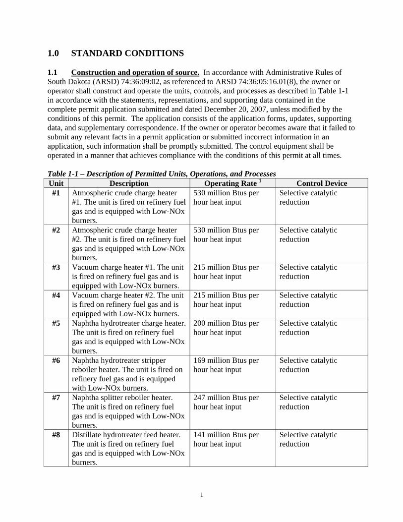
1.0 STANDARD CONDITIONS 1.1 Construction and operation of source. In accordance with Administrative Rules of South Dakota (ARSD) 74:36:09:02, as referenced to ARSD 74:36:05:16.01(8), the owner or operator shall construct and operate the units, controls, and processes as described in Table 1-1 in accordance with the statements, representations, and supporting data contained in the complete permit application submitted and dated December 20, 2007, unless modified by the conditions of this permit. The application consists of the application forms, updates, supporting data, and supplementary correspondence. If the owner or operator becomes aware that it failed to submit any relevant facts in a permit application or submitted incorrect information in an application, such information shall be promptly submitted. The control equipment shall be operated in a manner that achieves compliance with the conditions of this permit at all times. Table 1-1 – Description of Permitted Units, Operations, and Processes Unit Description Operating Rate 1 Control Device #1 Atmospheric crude charge heater
#1. The unit is fired on refinery fuel gas and is equipped with Low-NOx burners.
530 million Btus per hour heat input
Selective catalytic reduction
#2 Atmospheric crude charge heater #2. The unit is fired on refinery fuel gas and is equipped with Low-NOx burners.
530 million Btus per hour heat input
Selective catalytic reduction
#3 Vacuum charge heater #1. The unit is fired on refinery fuel gas and is equipped with Low-NOx burners.
215 million Btus per hour heat input
Selective catalytic reduction
#4 Vacuum charge heater #2. The unit is fired on refinery fuel gas and is equipped with Low-NOx burners.
215 million Btus per hour heat input
Selective catalytic reduction
#5 Naphtha hydrotreater charge heater. The unit is fired on refinery fuel gas and is equipped with Low-NOx burners.
200 million Btus per hour heat input
Selective catalytic reduction
#6 Naphtha hydrotreater stripper reboiler heater. The unit is fired on refinery fuel gas and is equipped with Low-NOx burners.
169 million Btus per hour heat input
Selective catalytic reduction
#7 Naphtha splitter reboiler heater. The unit is fired on refinery fuel gas and is equipped with Low-NOx burners.
247 million Btus per hour heat input
Selective catalytic reduction
#8 Distillate hydrotreater feed heater. The unit is fired on refinery fuel gas and is equipped with Low-NOx burners.
141 million Btus per hour heat input
Selective catalytic reduction
1
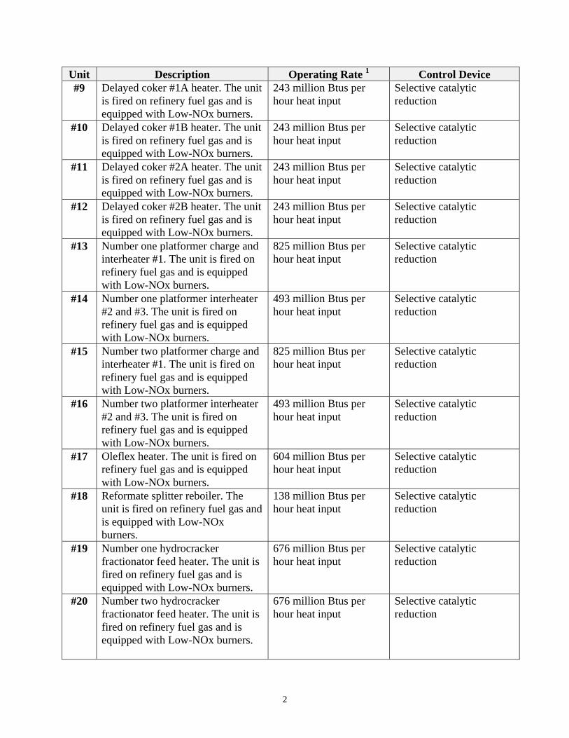
Unit Description Operating Rate 1 Control Device #9 Delayed coker #1A heater. The unit
is fired on refinery fuel gas and is equipped with Low-NOx burners.
243 million Btus per hour heat input
Selective catalytic reduction
#10 Delayed coker #1B heater. The unit is fired on refinery fuel gas and is equipped with Low-NOx burners.
243 million Btus per hour heat input
Selective catalytic reduction
#11 Delayed coker #2A heater. The unit is fired on refinery fuel gas and is equipped with Low-NOx burners.
243 million Btus per hour heat input
Selective catalytic reduction
#12 Delayed coker #2B heater. The unit is fired on refinery fuel gas and is equipped with Low-NOx burners.
243 million Btus per hour heat input
Selective catalytic reduction
#13 Number one platformer charge and interheater #1. The unit is fired on refinery fuel gas and is equipped with Low-NOx burners.
825 million Btus per hour heat input
Selective catalytic reduction
#14 Number one platformer interheater #2 and #3. The unit is fired on refinery fuel gas and is equipped with Low-NOx burners.
493 million Btus per hour heat input
Selective catalytic reduction
#15 Number two platformer charge and interheater #1. The unit is fired on refinery fuel gas and is equipped with Low-NOx burners.
825 million Btus per hour heat input
Selective catalytic reduction
#16 Number two platformer interheater #2 and #3. The unit is fired on refinery fuel gas and is equipped with Low-NOx burners.
493 million Btus per hour heat input
Selective catalytic reduction
#17 Oleflex heater. The unit is fired on refinery fuel gas and is equipped with Low-NOx burners.
604 million Btus per hour heat input
Selective catalytic reduction
#18 Reformate splitter reboiler. The unit is fired on refinery fuel gas and is equipped with Low-NOx burners.
138 million Btus per hour heat input
Selective catalytic reduction
#19 Number one hydrocracker fractionator feed heater. The unit is fired on refinery fuel gas and is equipped with Low-NOx burners.
676 million Btus per hour heat input
Selective catalytic reduction
#20 Number two hydrocracker fractionator feed heater. The unit is fired on refinery fuel gas and is equipped with Low-NOx burners.
676 million Btus per hour heat input
Selective catalytic reduction
2
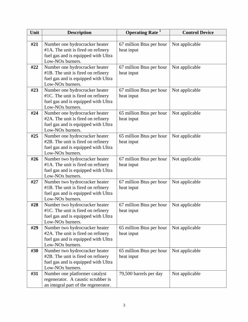
Unit Description Operating Rate 1 Control Device
#21 Number one hydrocracker heater #1A. The unit is fired on refinery fuel gas and is equipped with Ultra Low-NOx burners.
67 million Btus per hour heat input
Not applicable
#22 Number one hydrocracker heater #1B. The unit is fired on refinery fuel gas and is equipped with Ultra Low-NOx burners.
67 million Btus per hour heat input
Not applicable
#23 Number one hydrocracker heater #1C. The unit is fired on refinery fuel gas and is equipped with Ultra Low-NOx burners.
67 million Btus per hour heat input
Not applicable
#24 Number one hydrocracker heater #2A. The unit is fired on refinery fuel gas and is equipped with Ultra Low-NOx burners.
65 million Btus per hour heat input
Not applicable
#25 Number one hydrocracker heater #2B. The unit is fired on refinery fuel gas and is equipped with Ultra Low-NOx burners.
65 million Btus per hour heat input
Not applicable
#26 Number two hydrocracker heater #1A. The unit is fired on refinery fuel gas and is equipped with Ultra Low-NOx burners.
67 million Btus per hour heat input
Not applicable
#27 Number two hydrocracker heater #1B. The unit is fired on refinery fuel gas and is equipped with Ultra Low-NOx burners.
67 million Btus per hour heat input
Not applicable
#28 Number two hydrocracker heater #1C. The unit is fired on refinery fuel gas and is equipped with Ultra Low-NOx burners.
67 million Btus per hour heat input
Not applicable
#29 Number two hydrocracker heater #2A. The unit is fired on refinery fuel gas and is equipped with Ultra Low-NOx burners.
65 million Btus per hour heat input
Not applicable
#30 Number two hydrocracker heater #2B. The unit is fired on refinery fuel gas and is equipped with Ultra Low-NOx burners.
65 million Btus per hour heat input
Not applicable
#31 Number one platformer catalyst regenerator. A caustic scrubber is an integral part of the regenerator.
79,500 barrels per day Not applicable
3
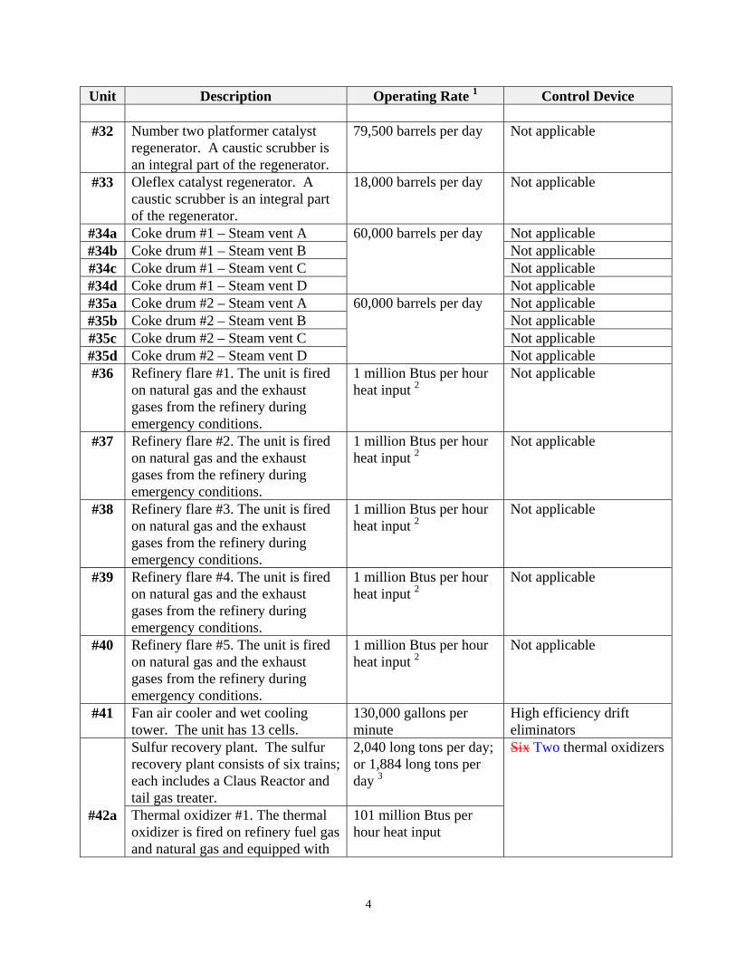
Unit Description Operating Rate 1 Control Device
#32 Number two platformer catalyst regenerator. A caustic scrubber is an integral part of the regenerator.
79,500 barrels per day Not applicable
#33 Oleflex catalyst regenerator. A caustic scrubber is an integral part of the regenerator.
18,000 barrels per day Not applicable
#34a Coke drum #1 – Steam vent A 60,000 barrels per day Not applicable #34b Coke drum #1 – Steam vent B Not applicable #34c Coke drum #1 – Steam vent C Not applicable #34d Coke drum #1 – Steam vent D Not applicable #35a Coke drum #2 – Steam vent A 60,000 barrels per day Not applicable #35b Coke drum #2 – Steam vent B Not applicable #35c Coke drum #2 – Steam vent C Not applicable #35d Coke drum #2 – Steam vent D Not applicable #36 Refinery flare #1. The unit is fired
on natural gas and the exhaust gases from the refinery during emergency conditions.
1 million Btus per hour heat input 2
Not applicable
#37 Refinery flare #2. The unit is fired on natural gas and the exhaust gases from the refinery during emergency conditions.
1 million Btus per hour heat input 2
Not applicable
#38 Refinery flare #3. The unit is fired on natural gas and the exhaust gases from the refinery during emergency conditions.
1 million Btus per hour heat input 2
Not applicable
#39 Refinery flare #4. The unit is fired on natural gas and the exhaust gases from the refinery during emergency conditions.
1 million Btus per hour heat input 2
Not applicable
#40 Refinery flare #5. The unit is fired on natural gas and the exhaust gases from the refinery during emergency conditions.
1 million Btus per hour heat input 2
Not applicable
#41 Fan air cooler and wet cooling tower. The unit has 13 cells.
130,000 gallons per minute
High efficiency drift eliminators
Sulfur recovery plant. The sulfur recovery plant consists of six trains; each includes a Claus Reactor and tail gas treater.
2,040 long tons per day; or 1,884 long tons per day 3
Six Two thermal oxidizers
#42a Thermal oxidizer #1. The thermal oxidizer is fired on refinery fuel gas and natural gas and equipped with
101 million Btus per hour heat input
4
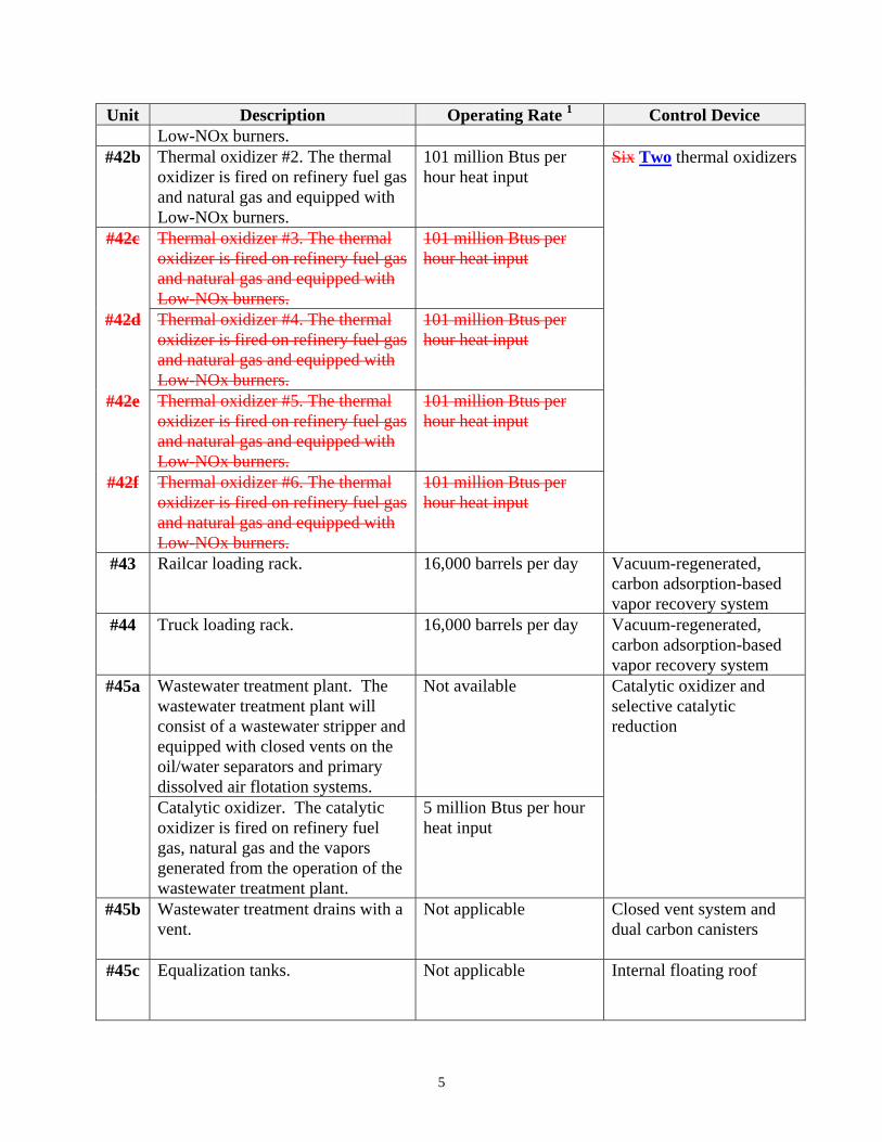
Unit Description Operating Rate 1 Control Device Low-NOx burners.
#42b Thermal oxidizer #2. The thermal oxidizer is fired on refinery fuel gas and natural gas and equipped with Low-NOx burners.
101 million Btus per hour heat input
Six Two thermal oxidizers
#42c Thermal oxidizer #3. The thermal oxidizer is fired on refinery fuel gas and natural gas and equipped with Low-NOx burners.
101 million Btus per hour heat input
#42d Thermal oxidizer #4. The thermal oxidizer is fired on refinery fuel gas and natural gas and equipped with Low-NOx burners.
101 million Btus per hour heat input
#42e Thermal oxidizer #5. The thermal oxidizer is fired on refinery fuel gas and natural gas and equipped with Low-NOx burners.
101 million Btus per hour heat input
#42f Thermal oxidizer #6. The thermal oxidizer is fired on refinery fuel gas and natural gas and equipped with Low-NOx burners.
101 million Btus per hour heat input
#43 Railcar loading rack. 16,000 barrels per day Vacuum-regenerated, carbon adsorption-based vapor recovery system
#44 Truck loading rack. 16,000 barrels per day Vacuum-regenerated, carbon adsorption-based vapor recovery system
#45a Wastewater treatment plant. The wastewater treatment plant will consist of a wastewater stripper and equipped with closed vents on the oil/water separators and primary dissolved air flotation systems.
Not available Catalytic oxidizer and selective catalytic reduction
Catalytic oxidizer. The catalytic oxidizer is fired on refinery fuel gas, natural gas and the vapors generated from the operation of the wastewater treatment plant.
5 million Btus per hour heat input
#45b Wastewater treatment drains with a vent.
Not applicable Closed vent system and dual carbon canisters
#45c Equalization tanks.
Not applicable Internal floating roof
5
Unit Description Operating Rate 1 Control Device
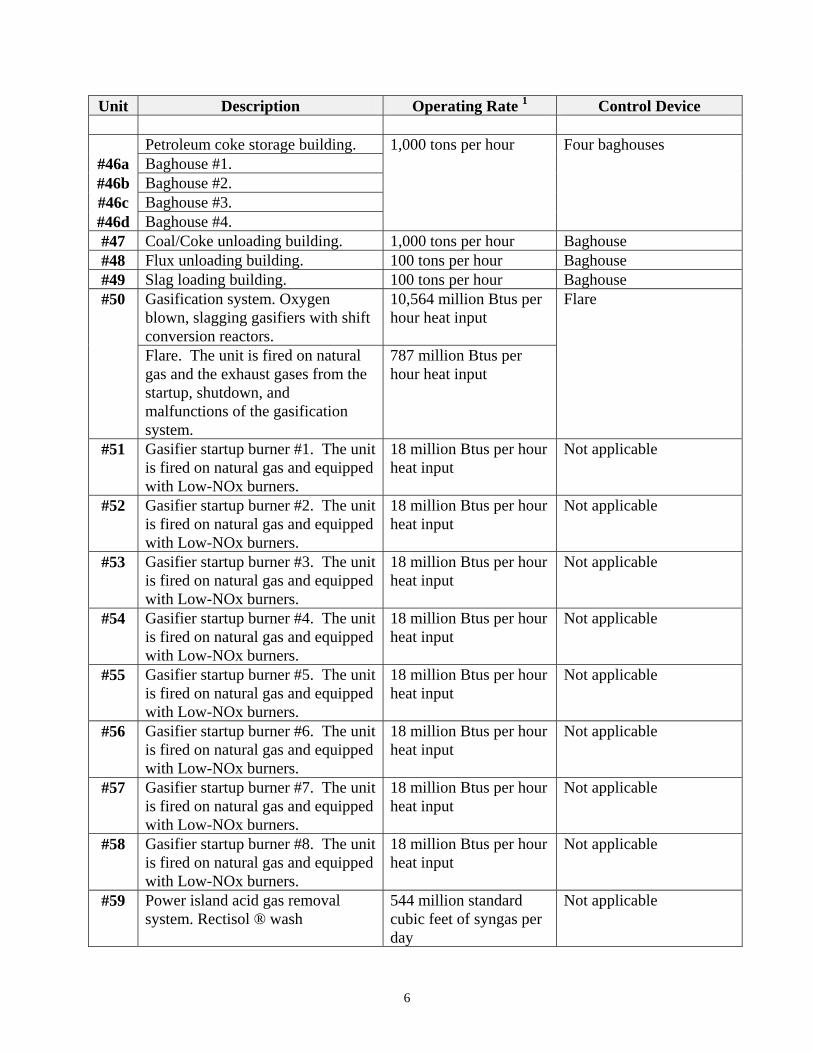
Petroleum coke storage building. 1,000 tons per hour Four baghouses #46a Baghouse #1. #46b Baghouse #2. #46c Baghouse #3. #46d Baghouse #4. #47 Coal/Coke unloading building. 1,000 tons per hour Baghouse #48 Flux unloading building. 100 tons per hour Baghouse #49 Slag loading building. 100 tons per hour Baghouse #50 Gasification system. Oxygen
blown, slagging gasifiers with shift conversion reactors.
10,564 million Btus per hour heat input
Flare
Flare. The unit is fired on natural gas and the exhaust gases from the startup, shutdown, and malfunctions of the gasification system.
787 million Btus per hour heat input
#51 Gasifier startup burner #1. The unit is fired on natural gas and equipped with Low-NOx burners.
18 million Btus per hour heat input
Not applicable
#52 Gasifier startup burner #2. The unit is fired on natural gas and equipped with Low-NOx burners.
18 million Btus per hour heat input
Not applicable
#53 Gasifier startup burner #3. The unit is fired on natural gas and equipped with Low-NOx burners.
18 million Btus per hour heat input
Not applicable
#54 Gasifier startup burner #4. The unit is fired on natural gas and equipped with Low-NOx burners.
18 million Btus per hour heat input
Not applicable
#55 Gasifier startup burner #5. The unit is fired on natural gas and equipped with Low-NOx burners.
18 million Btus per hour heat input
Not applicable
#56 Gasifier startup burner #6. The unit is fired on natural gas and equipped with Low-NOx burners.
18 million Btus per hour heat input
Not applicable
#57 Gasifier startup burner #7. The unit is fired on natural gas and equipped with Low-NOx burners.
18 million Btus per hour heat input
Not applicable
#58 Gasifier startup burner #8. The unit is fired on natural gas and equipped with Low-NOx burners.
18 million Btus per hour heat input
Not applicable
#59 Power island acid gas removal system. Rectisol ® wash
544 million standard cubic feet of syngas per day
Not applicable
6
Unit Description Operating Rate 1 Control Device
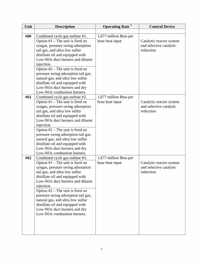
#60 Combined cycle gas turbine #1. 1,677 million Btus per Option #1 – The unit is fired on
syngas, pressure swing adsorption tail gas, and ultra low sulfur distillate oil and equipped with Low-NOx duct burners and diluent injection.
hour heat input Catalytic reactor system and selective catalytic reduction
Option #2 – The unit is fired on pressure swing adsorption tail gas, natural gas, and ultra low sulfur distillate oil and equipped with Low-NOx duct burners and dry Low-NOx combustion burners.
#61 Combined cycle gas turbine #2. 1,677 million Btus per Option #1 – The unit is fired on
syngas, pressure swing adsorption tail gas, and ultra low sulfur distillate oil and equipped with Low-NOx duct burners and diluent injection.
hour heat input Catalytic reactor system and selective catalytic reduction
Option #2 – The unit is fired on pressure swing adsorption tail gas, natural gas, and ultra low sulfur distillate oil and equipped with Low-NOx duct burners and dry Low-NOx combustion burners.
#62 Combined cycle gas turbine #3. 1,677 million Btus per Option #1 – The unit is fired on
syngas, pressure swing adsorption tail gas, and ultra low sulfur distillate oil and equipped with Low-NOx duct burners and diluent injection.
hour heat input Catalytic reactor system and selective catalytic reduction
Option #2 – The unit is fired on pressure swing adsorption tail gas, natural gas, and ultra low sulfur distillate oil and equipped with Low-NOx duct burners and dry Low-NOx combustion burners.
7
Unit Description Operating Rate 1 Control Device
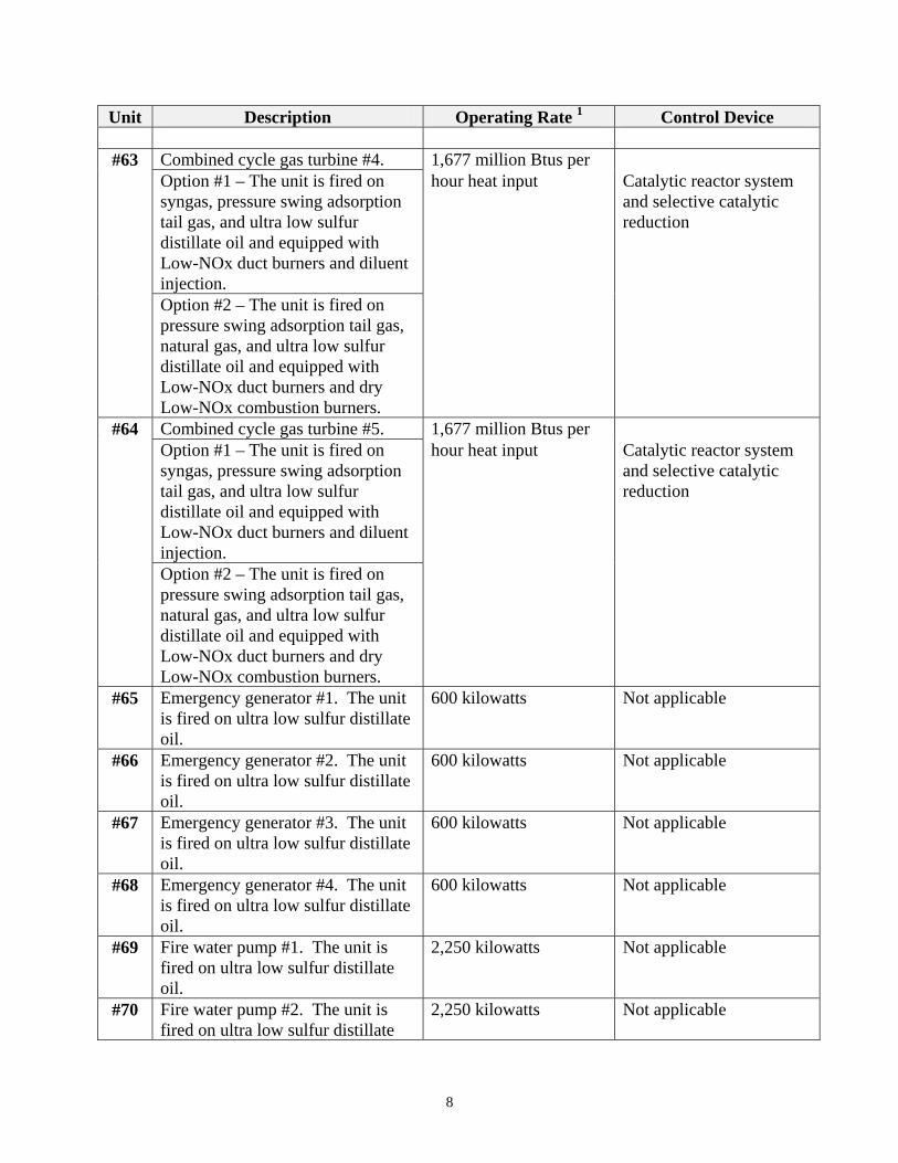
#63 Combined cycle gas turbine #4. 1,677 million Btus per Option #1 – The unit is fired on
syngas, pressure swing adsorption tail gas, and ultra low sulfur distillate oil and equipped with Low-NOx duct burners and diluent injection.
hour heat input Catalytic reactor system and selective catalytic reduction
Option #2 – The unit is fired on pressure swing adsorption tail gas, natural gas, and ultra low sulfur distillate oil and equipped with Low-NOx duct burners and dry Low-NOx combustion burners.
#64 Combined cycle gas turbine #5. 1,677 million Btus per Option #1 – The unit is fired on
syngas, pressure swing adsorption tail gas, and ultra low sulfur distillate oil and equipped with Low-NOx duct burners and diluent injection.
hour heat input Catalytic reactor system and selective catalytic reduction
Option #2 – The unit is fired on pressure swing adsorption tail gas, natural gas, and ultra low sulfur distillate oil and equipped with Low-NOx duct burners and dry Low-NOx combustion burners.
#65 Emergency generator #1. The unit is fired on ultra low sulfur distillate oil.
600 kilowatts Not applicable
#66 Emergency generator #2. The unit is fired on ultra low sulfur distillate oil.
600 kilowatts Not applicable
#67 Emergency generator #3. The unit is fired on ultra low sulfur distillate oil.
600 kilowatts Not applicable
#68 Emergency generator #4. The unit is fired on ultra low sulfur distillate oil.
600 kilowatts Not applicable
#69 Fire water pump #1. The unit is fired on ultra low sulfur distillate oil.
2,250 kilowatts Not applicable
#70 Fire water pump #2. The unit is fired on ultra low sulfur distillate
2,250 kilowatts Not applicable
8
Unit Description Operating Rate 1 Control Device oil.
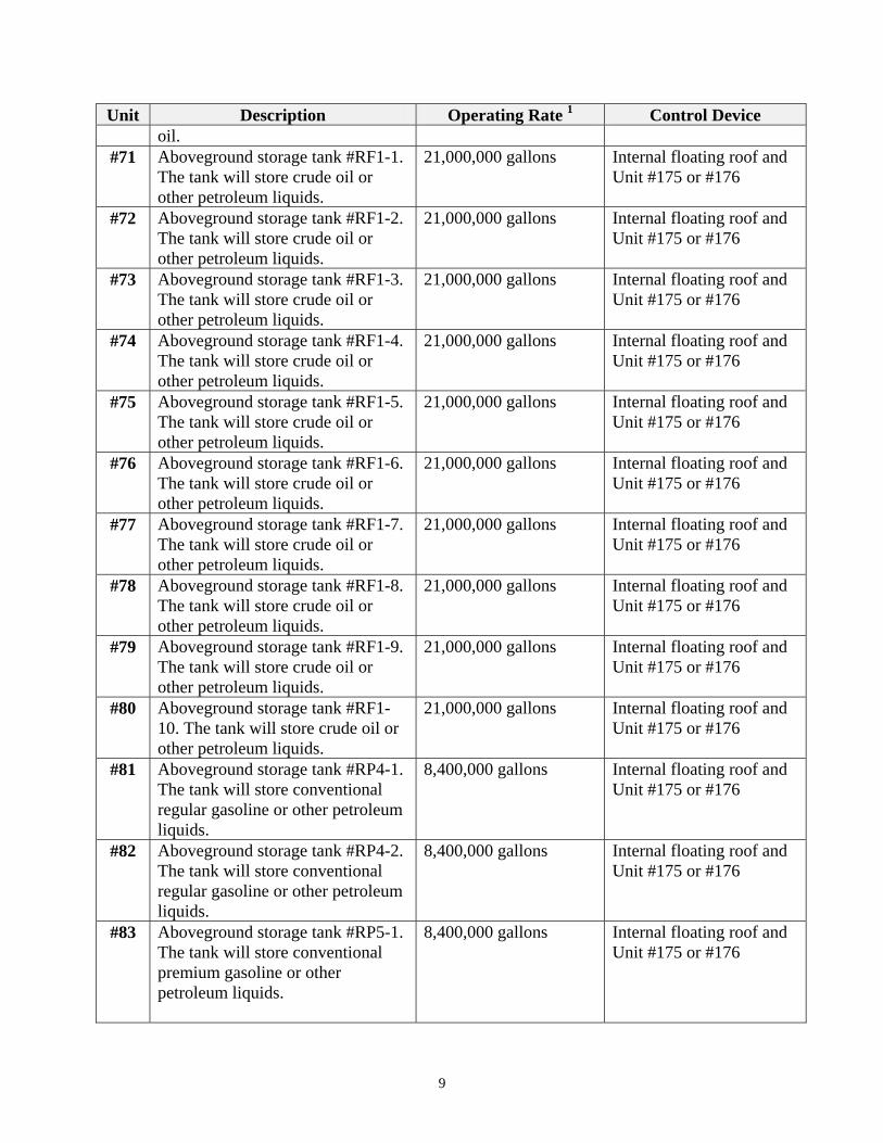
#71 Aboveground storage tank #RF1-1. The tank will store crude oil or other petroleum liquids.
21,000,000 gallons Internal floating roof and Unit #175 or #176
#72 Aboveground storage tank #RF1-2. The tank will store crude oil or other petroleum liquids.
21,000,000 gallons Internal floating roof and Unit #175 or #176
#73 Aboveground storage tank #RF1-3. The tank will store crude oil or other petroleum liquids.
21,000,000 gallons Internal floating roof and Unit #175 or #176
#74 Aboveground storage tank #RF1-4. The tank will store crude oil or other petroleum liquids.
21,000,000 gallons Internal floating roof and Unit #175 or #176
#75 Aboveground storage tank #RF1-5. The tank will store crude oil or other petroleum liquids.
21,000,000 gallons Internal floating roof and Unit #175 or #176
#76 Aboveground storage tank #RF1-6. The tank will store crude oil or other petroleum liquids.
21,000,000 gallons Internal floating roof and Unit #175 or #176
#77 Aboveground storage tank #RF1-7. The tank will store crude oil or other petroleum liquids.
21,000,000 gallons Internal floating roof and Unit #175 or #176
#78 Aboveground storage tank #RF1-8. The tank will store crude oil or other petroleum liquids.
21,000,000 gallons Internal floating roof and Unit #175 or #176
#79 Aboveground storage tank #RF1-9. The tank will store crude oil or other petroleum liquids.
21,000,000 gallons Internal floating roof and Unit #175 or #176
#80 Aboveground storage tank #RF1-10. The tank will store crude oil or other petroleum liquids.
21,000,000 gallons Internal floating roof and Unit #175 or #176
#81 Aboveground storage tank #RP4-1. The tank will store conventional regular gasoline or other petroleum liquids.
8,400,000 gallons Internal floating roof and Unit #175 or #176
#82 Aboveground storage tank #RP4-2. The tank will store conventional regular gasoline or other petroleum liquids.
8,400,000 gallons Internal floating roof and Unit #175 or #176
#83 Aboveground storage tank #RP5-1. The tank will store conventional premium gasoline or other petroleum liquids.
8,400,000 gallons Internal floating roof and Unit #175 or #176
9
Unit Description Operating Rate 1 Control Device
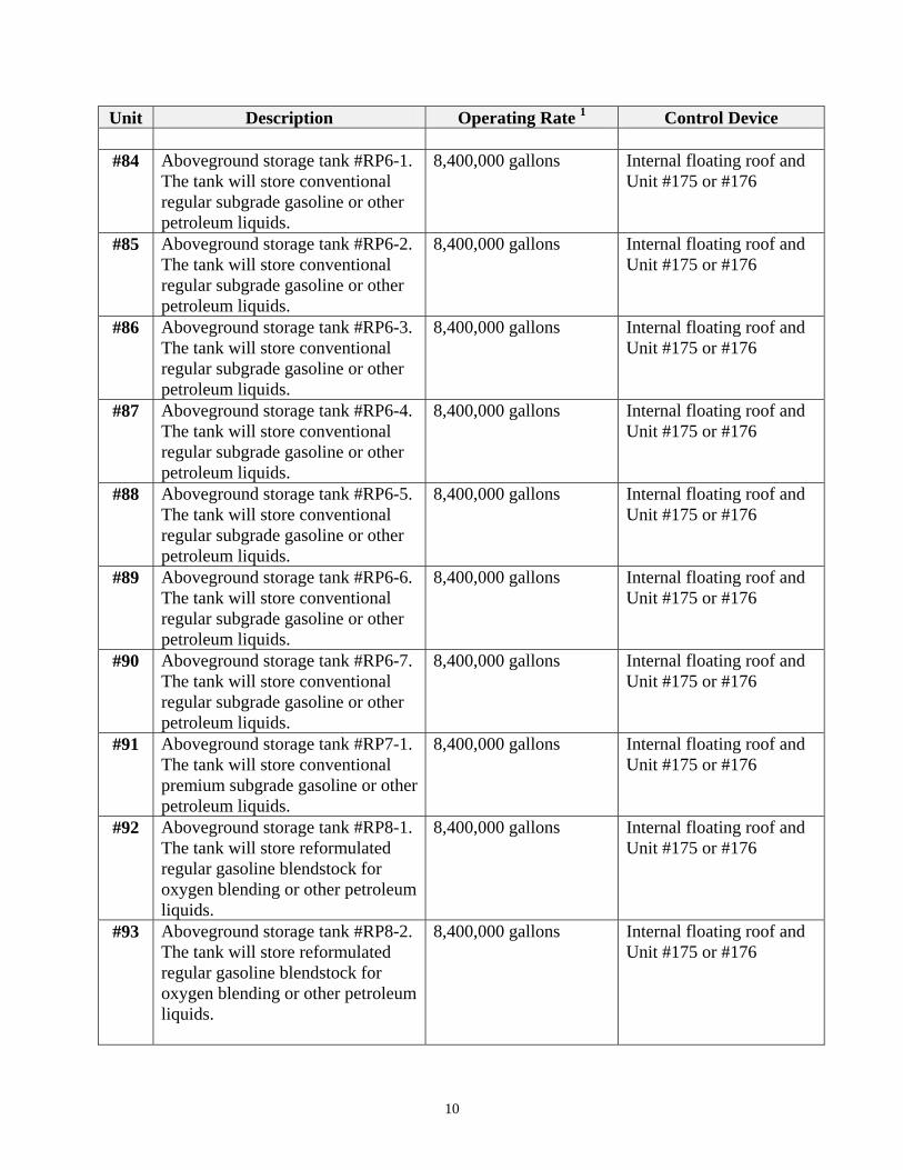
#84 Aboveground storage tank #RP6-1. The tank will store conventional regular subgrade gasoline or other petroleum liquids.
8,400,000 gallons Internal floating roof and Unit #175 or #176
#85 Aboveground storage tank #RP6-2. The tank will store conventional regular subgrade gasoline or other petroleum liquids.
8,400,000 gallons Internal floating roof and Unit #175 or #176
#86 Aboveground storage tank #RP6-3. The tank will store conventional regular subgrade gasoline or other petroleum liquids.
8,400,000 gallons Internal floating roof and Unit #175 or #176
#87 Aboveground storage tank #RP6-4. The tank will store conventional regular subgrade gasoline or other petroleum liquids.
8,400,000 gallons Internal floating roof and Unit #175 or #176
#88 Aboveground storage tank #RP6-5. The tank will store conventional regular subgrade gasoline or other petroleum liquids.
8,400,000 gallons Internal floating roof and Unit #175 or #176
#89 Aboveground storage tank #RP6-6. The tank will store conventional regular subgrade gasoline or other petroleum liquids.
8,400,000 gallons Internal floating roof and Unit #175 or #176
#90 Aboveground storage tank #RP6-7. The tank will store conventional regular subgrade gasoline or other petroleum liquids.
8,400,000 gallons Internal floating roof and Unit #175 or #176
#91 Aboveground storage tank #RP7-1. The tank will store conventional premium subgrade gasoline or other petroleum liquids.
8,400,000 gallons Internal floating roof and Unit #175 or #176
#92 Aboveground storage tank #RP8-1. The tank will store reformulated regular gasoline blendstock for oxygen blending or other petroleum liquids.
8,400,000 gallons Internal floating roof and Unit #175 or #176
#93 Aboveground storage tank #RP8-2. The tank will store reformulated regular gasoline blendstock for oxygen blending or other petroleum liquids.
8,400,000 gallons Internal floating roof and Unit #175 or #176
10
Unit Description Operating Rate 1 Control Device
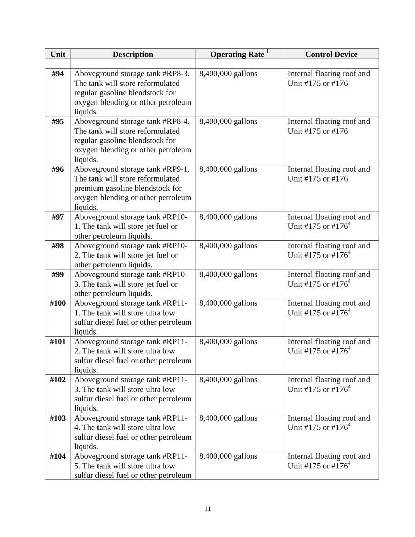
#94 Aboveground storage tank #RP8-3. The tank will store reformulated regular gasoline blendstock for oxygen blending or other petroleum liquids.
8,400,000 gallons Internal floating roof and Unit #175 or #176
#95 Aboveground storage tank #RP8-4. The tank will store reformulated regular gasoline blendstock for oxygen blending or other petroleum liquids.
8,400,000 gallons Internal floating roof and Unit #175 or #176
#96 Aboveground storage tank #RP9-1. The tank will store reformulated premium gasoline blendstock for oxygen blending or other petroleum liquids.
8,400,000 gallons Internal floating roof and Unit #175 or #176
#97 Aboveground storage tank #RP10-1. The tank will store jet fuel or other petroleum liquids.
8,400,000 gallons Internal floating roof and Unit #175 or #1764
#98 Aboveground storage tank #RP10-2. The tank will store jet fuel or other petroleum liquids.
8,400,000 gallons Internal floating roof and Unit #175 or #1764
#99 Aboveground storage tank #RP10-3. The tank will store jet fuel or other petroleum liquids.
8,400,000 gallons Internal floating roof and Unit #175 or #1764
#100 Aboveground storage tank #RP11-1. The tank will store ultra low sulfur diesel fuel or other petroleum liquids.
8,400,000 gallons Internal floating roof and Unit #175 or #1764
#101 Aboveground storage tank #RP11-2. The tank will store ultra low sulfur diesel fuel or other petroleum liquids.
8,400,000 gallons Internal floating roof and Unit #175 or #1764
#102 Aboveground storage tank #RP11-3. The tank will store ultra low sulfur diesel fuel or other petroleum liquids.
8,400,000 gallons Internal floating roof and Unit #175 or #1764
#103 Aboveground storage tank #RP11-4. The tank will store ultra low sulfur diesel fuel or other petroleum liquids.
8,400,000 gallons Internal floating roof and Unit #175 or #1764
#104 Aboveground storage tank #RP11-5. The tank will store ultra low sulfur diesel fuel or other petroleum
8,400,000 gallons Internal floating roof and Unit #175 or #1764
11
Unit Description Operating Rate 1 Control Device liquids.
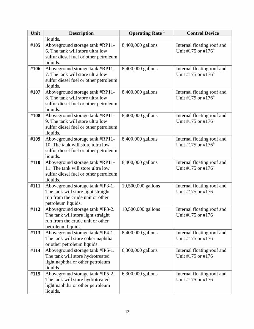
#105 Aboveground storage tank #RP11-6. The tank will store ultra low sulfur diesel fuel or other petroleum liquids.
8,400,000 gallons Internal floating roof and Unit #175 or #1764
#106 Aboveground storage tank #RP11-7. The tank will store ultra low sulfur diesel fuel or other petroleum liquids.
8,400,000 gallons Internal floating roof and Unit #175 or #1764
#107 Aboveground storage tank #RP11-8. The tank will store ultra low sulfur diesel fuel or other petroleum liquids.
8,400,000 gallons Internal floating roof and Unit #175 or #1764
#108 Aboveground storage tank #RP11-9. The tank will store ultra low sulfur diesel fuel or other petroleum liquids.
8,400,000 gallons Internal floating roof and Unit #175 or #1764
#109 Aboveground storage tank #RP11-10. The tank will store ultra low sulfur diesel fuel or other petroleum liquids.
8,400,000 gallons Internal floating roof and Unit #175 or #1764
#110 Aboveground storage tank #RP11-11. The tank will store ultra low sulfur diesel fuel or other petroleum liquids.
8,400,000 gallons Internal floating roof and Unit #175 or #1764
#111 Aboveground storage tank #IP3-1. The tank will store light straight run from the crude unit or other petroleum liquids.
10,500,000 gallons Internal floating roof and Unit #175 or #176
#112 Aboveground storage tank #IP3-2. The tank will store light straight run from the crude unit or other petroleum liquids.
10,500,000 gallons Internal floating roof and Unit #175 or #176
#113 Aboveground storage tank #IP4-1. The tank will store coker naphtha or other petroleum liquids.
8,400,000 gallons Internal floating roof and Unit #175 or #176
#114 Aboveground storage tank #IP5-1. The tank will store hydrotreated light naphtha or other petroleum liquids.
6,300,000 gallons Internal floating roof and Unit #175 or #176
#115 Aboveground storage tank #IP5-2. The tank will store hydrotreated light naphtha or other petroleum liquids.
6,300,000 gallons Internal floating roof and Unit #175 or #176
12
Unit Description Operating Rate 1 Control Device
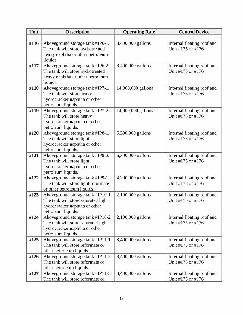
#116 Aboveground storage tank #IP6-1. The tank will store hydrotreated heavy naphtha or other petroleum liquids.
8,400,000 gallons Internal floating roof and Unit #175 or #176
#117 Aboveground storage tank #IP6-2. The tank will store hydrotreated heavy naphtha or other petroleum liquids.
8,400,000 gallons Internal floating roof and Unit #175 or #176
#118 Aboveground storage tank #IP7-1. The tank will store heavy hydrocracker naphtha or other petroleum liquids.
14,000,000 gallons Internal floating roof and Unit #175 or #176
#119 Aboveground storage tank #IP7-2. The tank will store heavy hydrocracker naphtha or other petroleum liquids.
14,000,000 gallons Internal floating roof and Unit #175 or #176
#120 Aboveground storage tank #IP8-1. The tank will store light hydrocracker naphtha or other petroleum liquids.
6,300,000 gallons Internal floating roof and Unit #175 or #176
#121 Aboveground storage tank #IP8-2. The tank will store light hydrocracker naphtha or other petroleum liquids.
6,300,000 gallons Internal floating roof and Unit #175 or #176
#122 Aboveground storage tank #IP9-1. The tank will store light reformate or other petroleum liquids.
4,200,000 gallons Internal floating roof and Unit #175 or #176
#123 Aboveground storage tank #IP10-1. The tank will store saturated light hydrocracker naphtha or other petroleum liquids.
2,100,000 gallons Internal floating roof and Unit #175 or #176
#124 Aboveground storage tank #IP10-2. The tank will store saturated light hydrocracker naphtha or other petroleum liquids.
2,100,000 gallons Internal floating roof and Unit #175 or #176
#125 Aboveground storage tank #IP11-1. The tank will store reformate or other petroleum liquids.
8,400,000 gallons Internal floating roof and Unit #175 or #176
#126 Aboveground storage tank #IP11-2. The tank will store reformate or other petroleum liquids.
8,400,000 gallons Internal floating roof and Unit #175 or #176
#127 Aboveground storage tank #IP11-3. The tank will store reformate or
8,400,000 gallons Internal floating roof and Unit #175 or #176
13
Unit Description Operating Rate 1 Control Device other petroleum liquids.
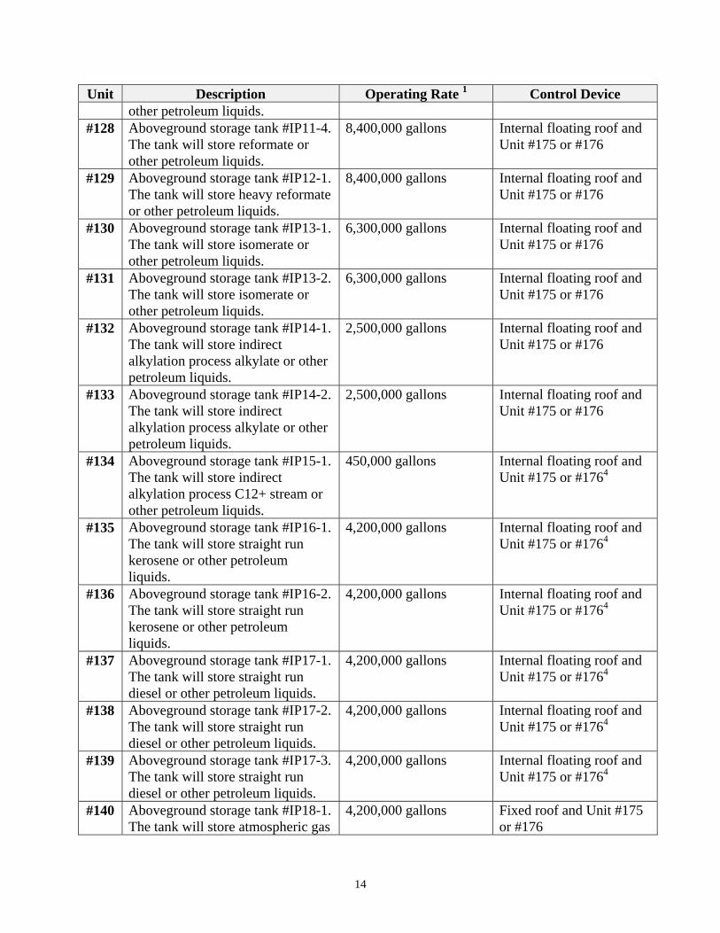
#128 Aboveground storage tank #IP11-4. The tank will store reformate or other petroleum liquids.
8,400,000 gallons Internal floating roof and Unit #175 or #176
#129 Aboveground storage tank #IP12-1. The tank will store heavy reformate or other petroleum liquids.
8,400,000 gallons Internal floating roof and Unit #175 or #176
#130 Aboveground storage tank #IP13-1. The tank will store isomerate or other petroleum liquids.
6,300,000 gallons Internal floating roof and Unit #175 or #176
#131 Aboveground storage tank #IP13-2. The tank will store isomerate or other petroleum liquids.
6,300,000 gallons Internal floating roof and Unit #175 or #176
#132 Aboveground storage tank #IP14-1. The tank will store indirect alkylation process alkylate or other petroleum liquids.
2,500,000 gallons Internal floating roof and Unit #175 or #176
#133 Aboveground storage tank #IP14-2. The tank will store indirect alkylation process alkylate or other petroleum liquids.
2,500,000 gallons Internal floating roof and Unit #175 or #176
#134 Aboveground storage tank #IP15-1. The tank will store indirect alkylation process C12+ stream or other petroleum liquids.
450,000 gallons Internal floating roof and Unit #175 or #1764
#135 Aboveground storage tank #IP16-1. The tank will store straight run kerosene or other petroleum liquids.
4,200,000 gallons Internal floating roof and Unit #175 or #1764
#136 Aboveground storage tank #IP16-2. The tank will store straight run kerosene or other petroleum liquids.
4,200,000 gallons Internal floating roof and Unit #175 or #1764
#137 Aboveground storage tank #IP17-1. The tank will store straight run diesel or other petroleum liquids.
4,200,000 gallons Internal floating roof and Unit #175 or #1764
#138 Aboveground storage tank #IP17-2. The tank will store straight run diesel or other petroleum liquids.
4,200,000 gallons Internal floating roof and Unit #175 or #1764
#139 Aboveground storage tank #IP17-3. The tank will store straight run diesel or other petroleum liquids.
4,200,000 gallons Internal floating roof and Unit #175 or #1764
#140 Aboveground storage tank #IP18-1. The tank will store atmospheric gas
4,200,000 gallons Fixed roof and Unit #175 or #176
14
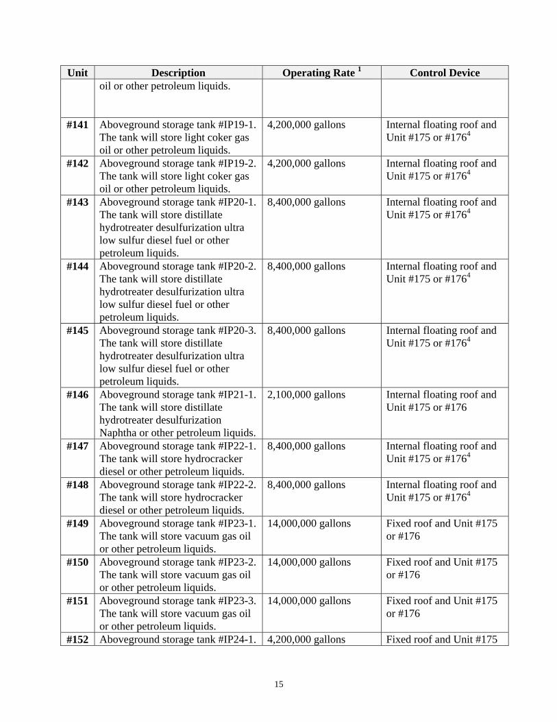
Unit Description Operating Rate 1 Control Device oil or other petroleum liquids.
#141 Aboveground storage tank #IP19-1. The tank will store light coker gas oil or other petroleum liquids.
4,200,000 gallons Internal floating roof and Unit #175 or #1764
#142 Aboveground storage tank #IP19-2. The tank will store light coker gas oil or other petroleum liquids.
4,200,000 gallons Internal floating roof and Unit #175 or #1764
#143 Aboveground storage tank #IP20-1. The tank will store distillate hydrotreater desulfurization ultra low sulfur diesel fuel or other petroleum liquids.
8,400,000 gallons Internal floating roof and Unit #175 or #1764
#144 Aboveground storage tank #IP20-2. The tank will store distillate hydrotreater desulfurization ultra low sulfur diesel fuel or other petroleum liquids.
8,400,000 gallons Internal floating roof and Unit #175 or #1764
#145 Aboveground storage tank #IP20-3. The tank will store distillate hydrotreater desulfurization ultra low sulfur diesel fuel or other petroleum liquids.
8,400,000 gallons Internal floating roof and Unit #175 or #1764
#146 Aboveground storage tank #IP21-1. The tank will store distillate hydrotreater desulfurization Naphtha or other petroleum liquids.
2,100,000 gallons Internal floating roof and Unit #175 or #176
#147 Aboveground storage tank #IP22-1. The tank will store hydrocracker diesel or other petroleum liquids.
8,400,000 gallons Internal floating roof and Unit #175 or #1764
#148 Aboveground storage tank #IP22-2. The tank will store hydrocracker diesel or other petroleum liquids.
8,400,000 gallons Internal floating roof and Unit #175 or #1764
#149 Aboveground storage tank #IP23-1. The tank will store vacuum gas oil or other petroleum liquids.
14,000,000 gallons Fixed roof and Unit #175 or #176
#150 Aboveground storage tank #IP23-2. The tank will store vacuum gas oil or other petroleum liquids.
14,000,000 gallons Fixed roof and Unit #175 or #176
#151 Aboveground storage tank #IP23-3. The tank will store vacuum gas oil or other petroleum liquids.
14,000,000 gallons Fixed roof and Unit #175 or #176
#152 Aboveground storage tank #IP24-1. 4,200,000 gallons Fixed roof and Unit #175
15
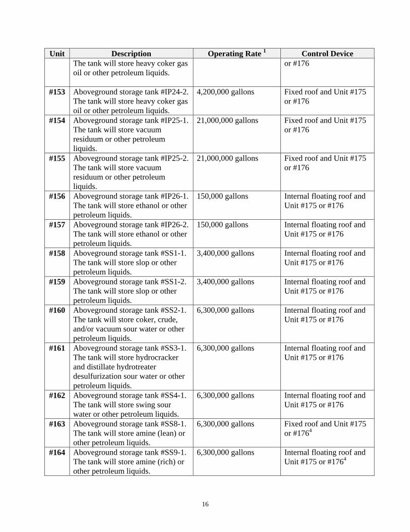
Unit Description Operating Rate 1 Control Device The tank will store heavy coker gas oil or other petroleum liquids.
or #176
#153 Aboveground storage tank #IP24-2. The tank will store heavy coker gas oil or other petroleum liquids.
4,200,000 gallons Fixed roof and Unit #175 or #176
#154 Aboveground storage tank #IP25-1. The tank will store vacuum residuum or other petroleum liquids.
21,000,000 gallons Fixed roof and Unit #175 or #176
#155 Aboveground storage tank #IP25-2. The tank will store vacuum residuum or other petroleum liquids.
21,000,000 gallons Fixed roof and Unit #175 or #176
#156 Aboveground storage tank #IP26-1. The tank will store ethanol or other petroleum liquids.
150,000 gallons Internal floating roof and Unit #175 or #176
#157 Aboveground storage tank #IP26-2. The tank will store ethanol or other petroleum liquids.
150,000 gallons Internal floating roof and Unit #175 or #176
#158 Aboveground storage tank #SS1-1. The tank will store slop or other petroleum liquids.
3,400,000 gallons Internal floating roof and Unit #175 or #176
#159 Aboveground storage tank #SS1-2. The tank will store slop or other petroleum liquids.
3,400,000 gallons Internal floating roof and Unit #175 or #176
#160 Aboveground storage tank #SS2-1. The tank will store coker, crude, and/or vacuum sour water or other petroleum liquids.
6,300,000 gallons Internal floating roof and Unit #175 or #176
#161 Aboveground storage tank #SS3-1. The tank will store hydrocracker and distillate hydrotreater desulfurization sour water or other petroleum liquids.
6,300,000 gallons Internal floating roof and Unit #175 or #176
#162 Aboveground storage tank #SS4-1. The tank will store swing sour water or other petroleum liquids.
6,300,000 gallons Internal floating roof and Unit #175 or #176
#163 Aboveground storage tank #SS8-1. The tank will store amine (lean) or other petroleum liquids.
6,300,000 gallons Fixed roof and Unit #175 or #1764
#164 Aboveground storage tank #SS9-1. The tank will store amine (rich) or other petroleum liquids.
6,300,000 gallons Internal floating roof and Unit #175 or #1764
16
Unit Description Operating Rate 1 Control Device
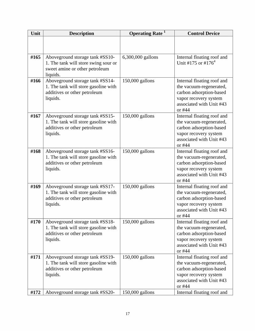
#165 Aboveground storage tank #SS10-1. The tank will store swing sour or sweet amine or other petroleum liquids.
6,300,000 gallons Internal floating roof and Unit #175 or #1764
#166 Aboveground storage tank #SS14-1. The tank will store gasoline with additives or other petroleum liquids.
150,000 gallons Internal floating roof and the vacuum-regenerated, carbon adsorption-based vapor recovery system associated with Unit #43 or #44
#167 Aboveground storage tank #SS15-1. The tank will store gasoline with additives or other petroleum liquids.
150,000 gallons Internal floating roof and the vacuum-regenerated, carbon adsorption-based vapor recovery system associated with Unit #43 or #44
#168 Aboveground storage tank #SS16-1. The tank will store gasoline with additives or other petroleum liquids.
150,000 gallons Internal floating roof and the vacuum-regenerated, carbon adsorption-based vapor recovery system associated with Unit #43 or #44
#169 Aboveground storage tank #SS17-1. The tank will store gasoline with additives or other petroleum liquids.
150,000 gallons Internal floating roof and the vacuum-regenerated, carbon adsorption-based vapor recovery system associated with Unit #43 or #44
#170 Aboveground storage tank #SS18-1. The tank will store gasoline with additives or other petroleum liquids.
150,000 gallons Internal floating roof and the vacuum-regenerated, carbon adsorption-based vapor recovery system associated with Unit #43 or #44
#171 Aboveground storage tank #SS19-1. The tank will store gasoline with additives or other petroleum liquids.
150,000 gallons Internal floating roof and the vacuum-regenerated, carbon adsorption-based vapor recovery system associated with Unit #43 or #44
#172 Aboveground storage tank #SS20- 150,000 gallons Internal floating roof and
17

Unit Description Operating Rate 1 Control Device 1. The tank will store kerosene with additives or other petroleum liquids.
Unit #175 or #1764
#173 Aboveground storage tank #SS21-1. The tank will store diesel with additives or other petroleum liquids.
140,000 gallons Internal floating roof and Unit #175 or #1764
#174 Aboveground storage tank #SS22-1. The tank will store methanol or other petroleum liquids.
31,000 gallons Internal floating roof and Unit #175 or #1764
#175 Tank farm thermal oxidizer. The thermal oxidizer may be fired on refinery gas, natural gas, and the vapors generated from the operation of the storage tanks. The thermal oxidizer will be equipped with Low-NOx burners.
Not applicable Not applicable
#176 Tank farm thermal oxidizer. The thermal oxidizer may be fired on refinery gas, natural gas, and the vapors generated from the operation of the storage tanks. The thermal oxidizer will be equipped with Low-NOx burners.
Not applicable Not applicable
#177 Coker Quench Water Handling. This includes the coker quench water surge tank, water pump pit and clarifier.
Not applicable Closed vent system on the water pump pit and clarifier and Unit #175 or #176
1 – The operating rate is the nominal or manufacturer listed operating rate noted in the PSD application and are descriptive only; 2 – Represents maximum design operating rate of the pilot gas flow rate; and 3 – The amount of sulfur produced per day is based on which fuel Option for the combined cycle combustion turbines. Option #1 consists of firing the combined cycle gas turbines with syngas, pressure swing adsorption tail gas; and distillate oil. Option #2 consists of firing the combined cycle gas turbines with pressure swing adsorption tail gas, natural gas, and distillate oil. 4 – The thermal oxidizer may or may not be required depending on the compliance option selected under permit condition 5.11
1.2 Duty to comply. In accordance with ARSD 74:36:09:02, as referenced to ARSD 74:36:05:16.01(12), the owner or operator shall comply with the conditions of this permit. An owner or operator who knowingly makes a false statement in any record or report or who falsifies, tampers with, or renders inaccurate, any monitoring device or method is in violation of this permit. A violation of any condition in this permit is grounds for enforcement, reopening this permit, permit termination, or denial of a permit renewal application. The owner or operator, in an enforcement action, cannot use the defense that it would have been necessary to cease or
18
reduce the permitted activity to maintain compliance. The owner or operator shall provide any information requested by the Secretary to determine compliance or whether cause exists for reopening or terminating this permit. 1.3 Property rights or exclusive privileges. In accordance with ARSD 74:36:09:02, as referenced to ARSD 74:36:05:16.01(12), the State’s issuance of this permit, adoption of design criteria, and approval of plans and specifications does not convey any property rights of any sort, any exclusive privileges, any authorization to damage, injure or use any private property, any authority to invade personal rights, any authority to violate federal, state or local laws or regulations, or any taking, condemnation or use of eminent domain against any property owned by third parties. The State does not warrant that the owner’s or operator’s compliance with this permit, design criteria, approved plans and specifications, and operation under this permit, will not cause damage, injury or use of private property, an invasion of personal rights, or violation of federal, state or local laws or regulations. The owner or operator is solely and severally liable for all damage, injury or use of private property, invasion of personal rights, infringement of federal, state or local laws and regulations, or taking or condemnation of property owned by third parties, which may result from actions taken under the permit. 1.4 Penalty for violating a permit condition. In accordance with South Dakota Codified Law (SDCL) 34A-1, a violation of a permit condition may subject the owner or operator to civil or criminal prosecution, a state penalty of not more than $10,000 per day per violation, injunctive action, administrative permit action, and other remedies as provided by law. 1.5 Inspection and entry. In accordance with SDCL 34A-1-41, the owner or operator shall allow the Secretary to: 1. Enter the premises where a regulated activity is located or where pertinent records are stored; 2. Have access to and copy any records that are required under this permit; 3. Inspect operations regulated under this permit; and/or 4. Sample or monitor any substances or parameters for the purpose of assuring compliance. 1.6 Severability. In accordance with ARSD 74:36:09:02, as referenced to ARSD 74:36:05:16.01(11), any portion of this permit that is void or challenged shall not affect the validity of the remaining permit requirements. 1.7 Credible evidence. In accordance with ARSD 74:36:13:07, credible evidence may be used for the purpose of establishing whether the owner or operator has violated or is violation of this permit. Credible evidence is as follows: 1. Information from the use of the following methods is presumptively credible evidence of
whether a violation has occurred at the source: a. A monitoring method approved for the source pursuant to 40 Code of Federal
Regulations (CFR) §70.6(a)(3) and incorporated in this permit; or b. Compliance methods specified in an applicable plan;
2. The following testing, monitoring, or information gathering methods are presumptively credible testing, monitoring, or information-gathering methods: a. Any monitoring or testing methods approved in this permit, including those in 40 CFR
Parts 51, 60, 61 and 75; or
19
b. Other testing, monitoring, or information-gathering methods that produce information comparable to that produced by any method in section (1) or (2)(a).
2.0 CONSTRUCTION AND OPERATING PERMIT DEADLINES 2.1 Commence construction. In accordance with ARSD 74:36:09:02, as referenced to 40 CFR §52.21(r)(2), the owner or operator shall commence construction within 18 months of the effective date of this permit by August 20, 2012. If construction is delayed or interrupted for a period of 18 months or more this permit becomes invalid. The owner or operator may apply, before the end of the 18-month period August 20, 2012, to the Secretary for an extension. The Secretary may grant an extension after the owner or operator satisfactorily demonstrates that an extension is justified. 2.2 Submit operating permit application. In accordance with ARSD 74:36:05:03.01, the owner or operator shall submit a complete permit application for a Title V air quality permit within 12 months after the initial startup of the petroleum refinery. For the purpose of this condition, commencing operation means the initial startup of the petroleum refinery, which is the first date that the petroleum refinery receives crude oil for processing. A complete permit application shall include all of the requirements specified in ARSD 74:36:05:12, including periodic monitoring and compliance assurance monitoring activities necessary to assure compliance. 2.3 Submit risk management plan. In accordance with 40 CFR Part 68, Subpart G, the owner or operator shall submit a risk management plan to EPA, if the owner or operator is applicable to 40 CFR Part 68, Subpart G. 3.0 RECORDKEEPING AND REPORTING REQUIREMENTS 3.1 Recordkeeping and reporting. In accordance with ARSD 74:36:09:02, as referenced to ARSD 74:36:05:16.01(9), the owner or operator shall maintain all monitoring data, records, reports, and pertinent information specified by this permit for five years from the date of sample, measurement, report, or application. The records shall be maintained on-site for the first two years and may be maintained off-site for the last three years. All records must be made available to the Secretary for inspection. All notifications and reports shall be submitted to the following address:
South Dakota Department of Environment and Natural Resources PMB 2020, Air Quality Program 523 E. Capitol, Joe Foss Building Pierre, SD 57501-3181
3.2 Signatory Requirements. In accordance with ARSD 74:36:09:02, as referenced to ARSD 74:36:05:12(17), all applications submitted to the Secretary shall be signed and certified
20
by a responsible official. A responsible official for a corporation is a responsible corporate officer and for a partnership or sole proprietorship is a general partner or the proprietor, respectively. All reports or other information submitted to the Secretary shall be signed and certified by a responsible official or a duly authorized representative. A person is a duly authorized representative only if: 1. The authorization is made in writing by a person described above and submitted to the
Secretary; and 2. The authorization specifies either an individual or a position having responsibility for the
overall operation of the regulated facility, such as the position of plant manager, superintendent, position of equivalent responsibility, or an individual or position having overall responsibility for environmental matters.
The responsible official shall notify the Secretary if an authorization is no longer accurate. The new duly authorized representative must be designated prior to or together with any reports or information to be signed by a duly authorized representative. 3.3 Certification statement. In accordance with ARSD 74:36:09:02, as referenced to ARSD 74:36:05:16.01(14)(a), all documents required by this permit, including reports, must be certified by a responsible official or a duly authorized representative. The certification shall include the following statement:
“I certify that based on information and belief formed after reasonable inquiry the statements and information in this document and all attachments are true, accurate, and complete.”
3.4 Construction date notification. In accordance with ARSD 74:36:09:02, as referenced to ARSD 74:36:05:16.01(9), the owner or operator shall notify the Secretary of the date construction commenced on the permanent structures for the petroleum refinery. The notification shall be postmarked within 15 days after the date construction commenced. 3.5 Initial startup notification. In accordance with ARSD 74:36:09:02, as referenced to ARSD 74:36:05:16.01(9), the owner or operator shall notify the Secretary of the initial startup date of the petroleum refinery. The notification shall be postmarked within 15 days after the date of initial startup. Initial startup of the petroleum refinery is the date the first gallon of crude oil is received by the facility to be refined. 3.6 Daily Monitoring log. In accordance with ARSD 74:36:09:02, as referenced to ARSD 74:36:05:16.01(9), the owner or operator must maintain a daily log. The daily log shall contain the following information: 1. Maintenance schedule for the air pollution control equipment specified in Table 1-1. At a
minimum, the maintenance schedule shall meet the manufacturer’s recommended schedule for maintenance. The following information shall be recorded for any maintenance performed: a. Identify the unit; b. The date and time maintenance was performed; c. Description of the type of maintenance; d. Reason for performing maintenance; and
21
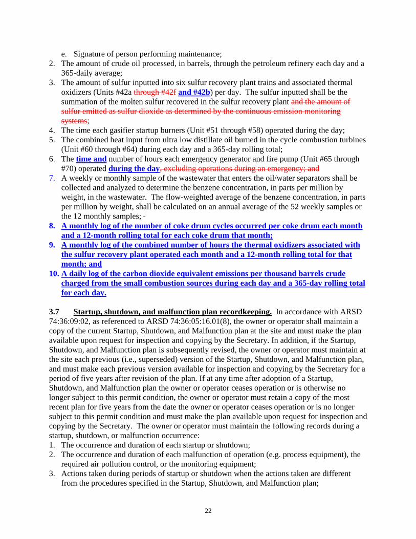
e. Signature of person performing maintenance; 2. The amount of crude oil processed, in barrels, through the petroleum refinery each day and a
365-daily average; 3. The amount of sulfur inputted into six sulfur recovery plant trains and associated thermal
oxidizers (Units #42a through #42f and #42b) per day. The sulfur inputted shall be the summation of the molten sulfur recovered in the sulfur recovery plant and the amount of sulfur emitted as sulfur dioxide as determined by the continuous emission monitoring systems;
4. The time each gasifier startup burners (Unit #51 through #58) operated during the day; 5. The combined heat input from ultra low distillate oil burned in the cycle combustion turbines
(Unit #60 through #64) during each day and a 365-day rolling total; 6. The time and number of hours each emergency generator and fire pump (Unit #65 through
#70) operated during the day, excluding operations during an emergency; and 7. A weekly or monthly sample of the wastewater that enters the oil/water separators shall be
collected and analyzed to determine the benzene concentration, in parts per million by weight, in the wastewater. The flow-weighted average of the benzene concentration, in parts per million by weight, shall be calculated on an annual average of the 52 weekly samples or the 12 monthly samples;
8. A monthly log of the number of coke drum cycles occurred per coke drum each month and a 12-month rolling total for each coke drum that month;
9. A monthly log of the combined number of hours the thermal oxidizers associated with the sulfur recovery plant operated each month and a 12-month rolling total for that month; and
10. A daily log of the carbon dioxide equivalent emissions per thousand barrels crude charged from the small combustion sources during each day and a 365-day rolling total for each day.
3.7 Startup, shutdown, and malfunction plan recordkeeping. In accordance with ARSD 74:36:09:02, as referenced to ARSD 74:36:05:16.01(8), the owner or operator shall maintain a copy of the current Startup, Shutdown, and Malfunction plan at the site and must make the plan available upon request for inspection and copying by the Secretary. In addition, if the Startup, Shutdown, and Malfunction plan is subsequently revised, the owner or operator must maintain at the site each previous (i.e., superseded) version of the Startup, Shutdown, and Malfunction plan, and must make each previous version available for inspection and copying by the Secretary for a period of five years after revision of the plan. If at any time after adoption of a Startup, Shutdown, and Malfunction plan the owner or operator ceases operation or is otherwise no longer subject to this permit condition, the owner or operator must retain a copy of the most recent plan for five years from the date the owner or operator ceases operation or is no longer subject to this permit condition and must make the plan available upon request for inspection and copying by the Secretary. The owner or operator must maintain the following records during a startup, shutdown, or malfunction occurrence: 1. The occurrence and duration of each startup or shutdown; 2. The occurrence and duration of each malfunction of operation (e.g. process equipment), the
required air pollution control, or the monitoring equipment; 3. Actions taken during periods of startup or shutdown when the actions taken are different
from the procedures specified in the Startup, Shutdown, and Malfunction plan;
22
4. Actions taken during periods of a malfunction when the actions taken are different from the procedures specified in the Startup, Shutdown, and Malfunction plan; and
5. All information necessary, including actions taken, to demonstrate conformance with the Startup, Shutdown, and Malfunction plan.
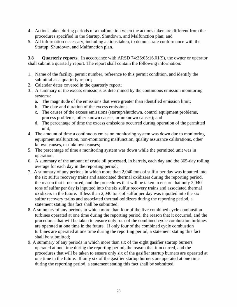
3.8 Quarterly reports. In accordance with ARSD 74:36:05:16.01(9), the owner or operator shall submit a quarterly report. The report shall contain the following information: 1. Name of the facility, permit number, reference to this permit condition, and identify the
submittal as a quarterly report; 2. Calendar dates covered in the quarterly report; 3. A summary of the excess emissions as determined by the continuous emission monitoring
systems: a. The magnitude of the emissions that were greater than identified emission limit; b. The date and duration of the excess emissions; c. The causes of the excess emissions (startup/shutdown, control equipment problems,
process problems, other known causes, or unknown causes); and d. The percentage of time the excess emissions occurred during operation of the permitted
unit; 4. The amount of time a continuous emission monitoring system was down due to monitoring
equipment malfunction, non-monitoring malfunction, quality assurance calibrations, other known causes, or unknown causes;
5. The percentage of time a monitoring system was down while the permitted unit was in operation;
6. A summary of the amount of crude oil processed, in barrels, each day and the 365-day rolling average for each day in the reporting period;
7. A summary of any periods in which more than 2,040 tons of sulfur per day was inputted into the six sulfur recovery trains and associated thermal oxidizers during the reporting period, the reason that it occurred, and the procedures that will be taken to ensure that only 2,040 tons of sulfur per day is inputted into the six sulfur recovery trains and associated thermal oxidizers in the future. If less than 2,040 tons of sulfur per day was inputted into the six sulfur recovery trains and associated thermal oxidizers during the reporting period, a statement stating this fact shall be submitted;
8. A summary of any periods in which more than four of the five combined cycle combustion turbines operated at one time during the reporting period, the reason that it occurred, and the procedures that will be taken to ensure only four of the combined cycle combustion turbines are operated at one time in the future. If only four of the combined cycle combustion turbines are operated at one time during the reporting period, a statement stating this fact shall be submitted;
9. A summary of any periods in which more than six of the eight gasifier startup burners operated at one time during the reporting period, the reason that it occurred, and the procedures that will be taken to ensure only six of the gasifier startup burners are operated at one time in the future. If only six of the gasifier startup burners are operated at one time during the reporting period, a statement stating this fact shall be submitted;
23
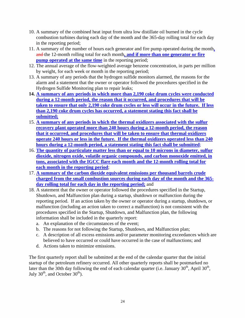
10. A summary of the combined heat input from ultra low distillate oil burned in the cycle combustion turbines during each day of the month and the 365-day rolling total for each day in the reporting period;
11. A summary of the number of hours each generator and fire pump operated during the month, and the 12-month rolling total for each month, and if more than one generator or fire pump operated at the same time in the reporting period;
12. The annual average of the flow-weighted average benzene concentration, in parts per million by weight, for each week or month in the reporting period;
13. A summary of any periods that the hydrogen sulfide monitors alarmed, the reasons for the alarm and a statement that the owner or operator followed the procedures specified in the Hydrogen Sulfide Monitoring plan to repair leaks;
14. A summary of any periods in which more than 2,190 coke drum cycles were conducted during a 12-month period, the reason that it occurred, and procedures that will be taken to ensure that only 2,190 coke drum cycles or less will occur in the future. If less than 2,190 coke drum cycles has occurred, a statement stating this fact shall be submitted;
15. A summary of any periods in which the thermal oxidizers associated with the sulfur recovery plant operated more than 240 hours during a 12-month period, the reason that it occurred, and procedures that will be taken to ensure that thermal oxidizers operate 240 hours or less in the future. If the thermal oxidizers operated less than 240 hours during a 12-month period, a statement stating this fact shall be submitted;
16. The quantity of particulate matter less than or equal to 10 microns in diameter, sulfur dioxide, nitrogen oxide, volatile organic compounds, and carbon monoxide emitted, in tons, associated with the IGCC flare each month and the 12-month rolling total for each month in the reporting period;
17. A summary of the carbon dioxide equivalent emissions per thousand barrels crude charged from the small combustion sources during each day of the month and the 365-day rolling total for each day in the reporting period; and
18. A statement that the owner or operator followed the procedures specified in the Startup, Shutdown, and Malfunction plan during a startup, shutdown or malfunction during the reporting period. If an action taken by the owner or operator during a startup, shutdown, or malfunction (including an action taken to correct a malfunction) is not consistent with the procedures specified in the Startup, Shutdown, and Malfunction plan, the following information shall be included in the quarterly report: a. An explanation of the circumstances of the event; b. The reasons for not following the Startup, Shutdown, and Malfunction plan; c. A description of all excess emissions and/or parameter monitoring exceedances which are
believed to have occurred or could have occurred in the case of malfunctions; and d. Actions taken to minimize emissions.
The first quarterly report shall be submitted at the end of the calendar quarter that the initial startup of the petroleum refinery occurred. All other quarterly reports shall be postmarked no later than the 30th day following the end of each calendar quarter (i.e. January 30th, April 30th, July 30th, and October 30th).
24
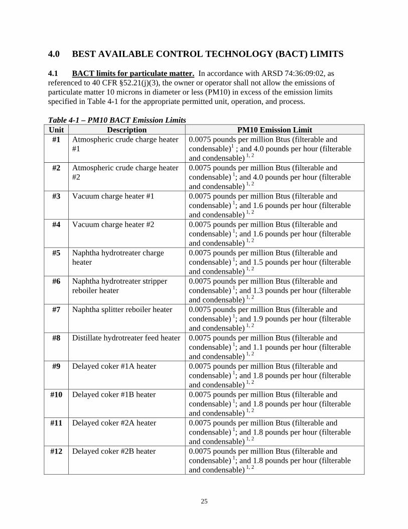
4.0 BEST AVAILABLE CONTROL TECHNOLOGY (BACT) LIMITS 4.1 BACT limits for particulate matter. In accordance with ARSD 74:36:09:02, as referenced to 40 CFR §52.21(j)(3), the owner or operator shall not allow the emissions of particulate matter 10 microns in diameter or less (PM10) in excess of the emission limits specified in Table 4-1 for the appropriate permitted unit, operation, and process. Table 4-1 – PM10 BACT Emission Limits Unit Description PM10 Emission Limit #1 Atmospheric crude charge heater
#1 0.0075 pounds per million Btus (filterable and condensable)1 ; and 4.0 pounds per hour (filterable and condensable) 1, 2
#2 Atmospheric crude charge heater #2
0.0075 pounds per million Btus (filterable and condensable) 1; and 4.0 pounds per hour (filterable and condensable) 1, 2
#3 Vacuum charge heater #1 0.0075 pounds per million Btus (filterable and condensable) 1; and 1.6 pounds per hour (filterable and condensable) 1, 2
#4 Vacuum charge heater #2 0.0075 pounds per million Btus (filterable and condensable) 1; and 1.6 pounds per hour (filterable and condensable) 1, 2
#5 Naphtha hydrotreater charge heater
0.0075 pounds per million Btus (filterable and condensable) 1; and 1.5 pounds per hour (filterable and condensable) 1, 2
#6 Naphtha hydrotreater stripper reboiler heater
0.0075 pounds per million Btus (filterable and condensable) 1; and 1.3 pounds per hour (filterable and condensable) 1, 2
#7 Naphtha splitter reboiler heater 0.0075 pounds per million Btus (filterable and condensable) 1; and 1.9 pounds per hour (filterable and condensable) 1, 2
#8 Distillate hydrotreater feed heater 0.0075 pounds per million Btus (filterable and condensable) 1; and 1.1 pounds per hour (filterable and condensable) 1, 2
#9 Delayed coker #1A heater 0.0075 pounds per million Btus (filterable and condensable) 1; and 1.8 pounds per hour (filterable and condensable) 1, 2
#10 Delayed coker #1B heater 0.0075 pounds per million Btus (filterable and condensable) 1; and 1.8 pounds per hour (filterable and condensable) 1, 2
#11 Delayed coker #2A heater 0.0075 pounds per million Btus (filterable and condensable) 1; and 1.8 pounds per hour (filterable and condensable) 1, 2
#12 Delayed coker #2B heater 0.0075 pounds per million Btus (filterable and condensable) 1; and 1.8 pounds per hour (filterable and condensable) 1, 2
25

Unit Description PM10 Emission Limit #13 Number one platformer charge
and interheater #1 0.0075 pounds per million Btus (filterable and condensable) 1; and 6.2 pounds per hour (filterable and condensable) 1, 2
#14 Number one platformer interheater #2 and #3
0.0075 pounds per million Btus (filterable and condensable) 1; and 3.7 pounds per hour (filterable and condensable) 1, 2
#15 Number two platformer charge and interheater #1
0.0075 pounds per million Btus (filterable and condensable) 1; and 6.2 pounds per hour (filterable and condensable) 1, 2
#16 Number two platformer interheater #2 and #3
0.0075 pounds per million Btus (filterable and condensable) 1; and 3.7 pounds per hour (filterable and condensable) 1, 2
#17 Oleflex heater 0.0075 pounds per million Btus (filterable and condensable) 1; and 4.5 pounds per hour (filterable and condensable) 1, 2
#18 Reformate splitter reboiler 0.0075 pounds per million Btus (filterable and condensable) 1; and 1.0 pounds per hour (filterable and condensable) 1, 2
#19 Number one hydrocracker fractionator feed heater
0.0075 pounds per million Btus (filterable and condensable) 1; and 5.1 pounds per hour (filterable and condensable) 1, 2
#20 Number two hydrocracker fractionator feed heater
0.0075 pounds per million Btus (filterable and condensable) 1; and 5.1 pounds per hour (filterable and condensable) 1, 2
#21 Number one hydrocracker heater #1A
0.0075 pounds per million Btus (filterable and condensable) 1; and 0.5 pounds per hour (filterable and condensable) 1, 2
#22 Number one hydrocracker heater #1B
0.0075 pounds per million Btus (filterable and condensable) 1; and 0.5 pounds per hour (filterable and condensable) 1, 2
#23 Number one hydrocracker heater #1C
0.0075 pounds per million Btus (filterable and condensable) 1; and 0.5 pounds per hour (filterable and condensable) 1, 2
#24 Number one hydrocracker heater #2A
0.0075 pounds per million Btus (filterable and condensable) 1; and 0.5 pounds per hour (filterable and condensable) 1, 2
#25 Number one hydrocracker heater #2B
0.0075 pounds per million Btus (filterable and condensable) 1; and 0.5 pounds per hour (filterable and condensable) 1, 2
#26 Number two hydrocracker heater #1A
0.0075 pounds per million Btus (filterable and condensable) 1; and 0.5 pounds per hour (filterable and condensable) 1, 2
#27 Number two hydrocracker heater #1B
0.0075 pounds per million Btus (filterable and condensable) 1; and 0.5 pounds per hour (filterable
26
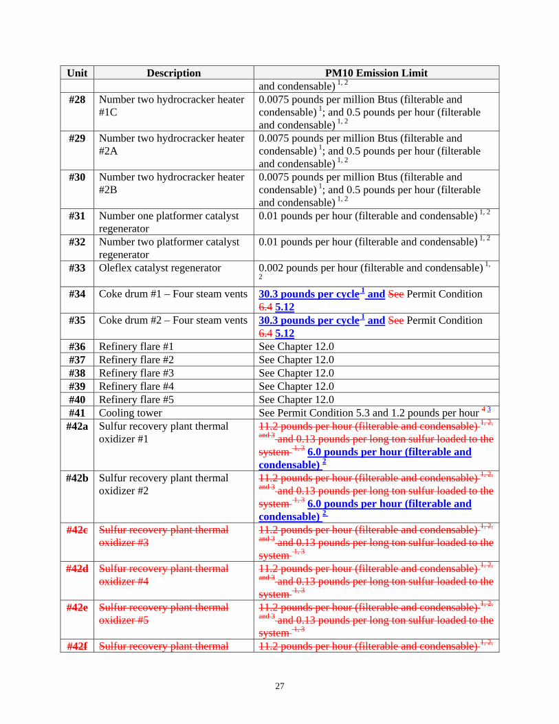
Unit Description PM10 Emission Limit and condensable) 1, 2
#28 Number two hydrocracker heater #1C
0.0075 pounds per million Btus (filterable and condensable) 1; and 0.5 pounds per hour (filterable and condensable) 1, 2
#29 Number two hydrocracker heater #2A
0.0075 pounds per million Btus (filterable and condensable) 1; and 0.5 pounds per hour (filterable and condensable) 1, 2
#30 Number two hydrocracker heater #2B
0.0075 pounds per million Btus (filterable and condensable) 1; and 0.5 pounds per hour (filterable and condensable) 1, 2
#31 Number one platformer catalyst regenerator
0.01 pounds per hour (filterable and condensable) 1, 2
#32 Number two platformer catalyst regenerator
0.01 pounds per hour (filterable and condensable) 1, 2
#33 Oleflex catalyst regenerator 0.002 pounds per hour (filterable and condensable) 1,
2
#34 Coke drum #1 – Four steam vents 30.3 pounds per cycle 1 and See Permit Condition 6.4 5.12
#35 Coke drum #2 – Four steam vents 30.3 pounds per cycle 1 and See Permit Condition 6.4 5.12
#36 Refinery flare #1 See Chapter 12.0 #37 Refinery flare #2 See Chapter 12.0 #38 Refinery flare #3 See Chapter 12.0 #39 Refinery flare #4 See Chapter 12.0 #40 Refinery flare #5 See Chapter 12.0 #41 Cooling tower See Permit Condition 5.3 and 1.2 pounds per hour 4 3
#42a Sulfur recovery plant thermal oxidizer #1
11.2 pounds per hour (filterable and condensable) 1, 2,
and 3 and 0.13 pounds per long ton sulfur loaded to the system 1, 3 6.0 pounds per hour (filterable and condensable) 2
#42b Sulfur recovery plant thermal oxidizer #2
11.2 pounds per hour (filterable and condensable) 1, 2,
and 3 and 0.13 pounds per long ton sulfur loaded to the system 1, 3 6.0 pounds per hour (filterable and condensable) 2
#42c Sulfur recovery plant thermal oxidizer #3
11.2 pounds per hour (filterable and condensable) 1, 2,
and 3 and 0.13 pounds per long ton sulfur loaded to the system 1, 3
#42d Sulfur recovery plant thermal oxidizer #4
11.2 pounds per hour (filterable and condensable) 1, 2,
and 3 and 0.13 pounds per long ton sulfur loaded to the system 1, 3
#42e Sulfur recovery plant thermal oxidizer #5
11.2 pounds per hour (filterable and condensable) 1, 2,
and 3 and 0.13 pounds per long ton sulfur loaded to the system 1, 3
#42f Sulfur recovery plant thermal 11.2 pounds per hour (filterable and condensable) 1, 2,
27
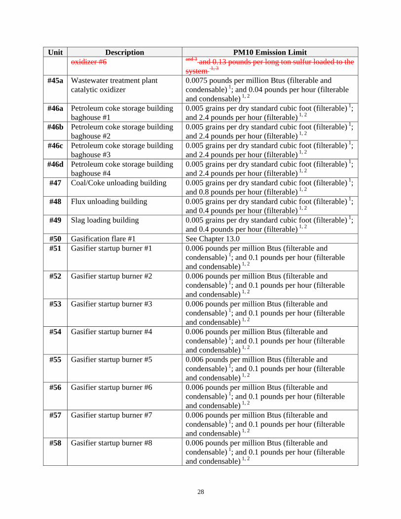
Unit Description PM10 Emission Limit oxidizer #6 and 3 and 0.13 pounds per long ton sulfur loaded to the
system 1, 3
#45a Wastewater treatment plant catalytic oxidizer
0.0075 pounds per million Btus (filterable and condensable) 1; and 0.04 pounds per hour (filterable and condensable) 1, 2
#46a Petroleum coke storage building baghouse #1
0.005 grains per dry standard cubic foot (filterable) 1; and 2.4 pounds per hour (filterable) 1, 2
#46b Petroleum coke storage building baghouse #2
0.005 grains per dry standard cubic foot (filterable) 1; and 2.4 pounds per hour (filterable) 1, 2
#46c Petroleum coke storage building baghouse #3
0.005 grains per dry standard cubic foot (filterable) 1; and 2.4 pounds per hour (filterable) 1, 2
#46d Petroleum coke storage building baghouse #4
0.005 grains per dry standard cubic foot (filterable) 1; and 2.4 pounds per hour (filterable) 1, 2
#47 Coal/Coke unloading building 0.005 grains per dry standard cubic foot (filterable) 1; and 0.8 pounds per hour (filterable) 1, 2
#48 Flux unloading building 0.005 grains per dry standard cubic foot (filterable) 1; and 0.4 pounds per hour (filterable) 1, 2
#49 Slag loading building 0.005 grains per dry standard cubic foot (filterable) 1; and 0.4 pounds per hour (filterable) 1, 2
#50 Gasification flare #1 See Chapter 13.0 #51 Gasifier startup burner #1 0.006 pounds per million Btus (filterable and
condensable) 1; and 0.1 pounds per hour (filterable and condensable) 1, 2
#52 Gasifier startup burner #2 0.006 pounds per million Btus (filterable and condensable) 1; and 0.1 pounds per hour (filterable and condensable) 1, 2
#53 Gasifier startup burner #3 0.006 pounds per million Btus (filterable and condensable) 1; and 0.1 pounds per hour (filterable and condensable) 1, 2
#54 Gasifier startup burner #4 0.006 pounds per million Btus (filterable and condensable) 1; and 0.1 pounds per hour (filterable and condensable) 1, 2
#55 Gasifier startup burner #5 0.006 pounds per million Btus (filterable and condensable) 1; and 0.1 pounds per hour (filterable and condensable) 1, 2
#56 Gasifier startup burner #6 0.006 pounds per million Btus (filterable and condensable) 1; and 0.1 pounds per hour (filterable and condensable) 1, 2
#57 Gasifier startup burner #7 0.006 pounds per million Btus (filterable and condensable) 1; and 0.1 pounds per hour (filterable and condensable) 1, 2
#58 Gasifier startup burner #8 0.006 pounds per million Btus (filterable and condensable) 1; and 0.1 pounds per hour (filterable and condensable) 1, 2
28
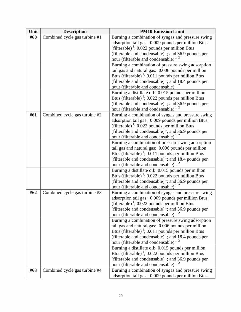
Unit Description PM10 Emission Limit #60 Combined cycle gas turbine #1 Burning a combination of syngas and pressure swing
adsorption tail gas: 0.009 pounds per million Btus (filterable) 1; 0.022 pounds per million Btus (filterable and condensable) 1; and 36.9 pounds per hour (filterable and condensable) 1, 2
Burning a combination of pressure swing adsorption tail gas and natural gas: 0.006 pounds per million Btus (filterable) 1; 0.011 pounds per million Btus (filterable and condensable) 1; and 18.4 pounds per hour (filterable and condensable) 1, 2
Burning a distillate oil: 0.015 pounds per million Btus (filterable) 1; 0.022 pounds per million Btus (filterable and condensable) 1; and 36.9 pounds per hour (filterable and condensable) 1, 2
#61 Combined cycle gas turbine #2 Burning a combination of syngas and pressure swing adsorption tail gas: 0.009 pounds per million Btus (filterable) 1; 0.022 pounds per million Btus (filterable and condensable) 1; and 36.9 pounds per hour (filterable and condensable) 1, 2
Burning a combination of pressure swing adsorption tail gas and natural gas: 0.006 pounds per million Btus (filterable) 1; 0.011 pounds per million Btus (filterable and condensable) 1; and 18.4 pounds per hour (filterable and condensable) 1, 2
Burning a distillate oil: 0.015 pounds per million Btus (filterable) 1; 0.022 pounds per million Btus (filterable and condensable) 1; and 36.9 pounds per hour (filterable and condensable) 1, 2
#62 Combined cycle gas turbine #3 Burning a combination of syngas and pressure swing adsorption tail gas: 0.009 pounds per million Btus (filterable) 1; 0.022 pounds per million Btus (filterable and condensable) 1; and 36.9 pounds per hour (filterable and condensable) 1, 2
Burning a combination of pressure swing adsorption tail gas and natural gas: 0.006 pounds per million Btus (filterable) 1; 0.011 pounds per million Btus (filterable and condensable) 1; and 18.4 pounds per hour (filterable and condensable) 1, 2
Burning a distillate oil: 0.015 pounds per million Btus (filterable) 1; 0.022 pounds per million Btus (filterable and condensable) 1; and 36.9 pounds per hour (filterable and condensable) 1, 2
#63 Combined cycle gas turbine #4 Burning a combination of syngas and pressure swing adsorption tail gas: 0.009 pounds per million Btus
29
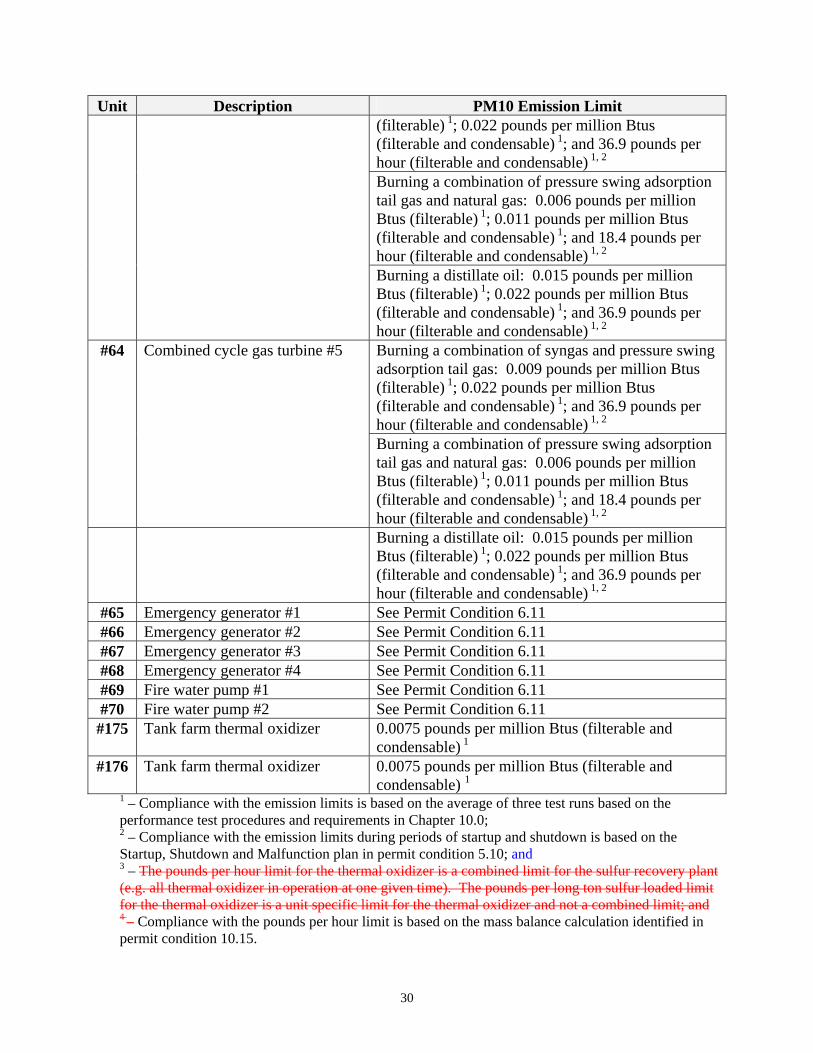
Unit Description PM10 Emission Limit (filterable) 1; 0.022 pounds per million Btus (filterable and condensable) 1; and 36.9 pounds per hour (filterable and condensable) 1, 2
Burning a combination of pressure swing adsorption tail gas and natural gas: 0.006 pounds per million Btus (filterable) 1; 0.011 pounds per million Btus (filterable and condensable) 1; and 18.4 pounds per hour (filterable and condensable) 1, 2
Burning a distillate oil: 0.015 pounds per million Btus (filterable) 1; 0.022 pounds per million Btus (filterable and condensable) 1; and 36.9 pounds per hour (filterable and condensable) 1, 2
#64 Combined cycle gas turbine #5 Burning a combination of syngas and pressure swing adsorption tail gas: 0.009 pounds per million Btus (filterable) 1; 0.022 pounds per million Btus (filterable and condensable) 1; and 36.9 pounds per hour (filterable and condensable) 1, 2
Burning a combination of pressure swing adsorption tail gas and natural gas: 0.006 pounds per million Btus (filterable) 1; 0.011 pounds per million Btus (filterable and condensable) 1; and 18.4 pounds per hour (filterable and condensable) 1, 2
Burning a distillate oil: 0.015 pounds per million Btus (filterable) 1; 0.022 pounds per million Btus (filterable and condensable) 1; and 36.9 pounds per hour (filterable and condensable) 1, 2
#65 Emergency generator #1 See Permit Condition 6.11 #66 Emergency generator #2 See Permit Condition 6.11 #67 Emergency generator #3 See Permit Condition 6.11 #68 Emergency generator #4 See Permit Condition 6.11 #69 Fire water pump #1 See Permit Condition 6.11 #70 Fire water pump #2 See Permit Condition 6.11 #175 Tank farm thermal oxidizer 0.0075 pounds per million Btus (filterable and
condensable) 1 #176 Tank farm thermal oxidizer 0.0075 pounds per million Btus (filterable and
condensable) 11 – Compliance with the emission limits is based on the average of three test runs based on the performance test procedures and requirements in Chapter 10.0; 2 – Compliance with the emission limits during periods of startup and shutdown is based on the Startup, Shutdown and Malfunction plan in permit condition 5.10; and 3 – The pounds per hour limit for the thermal oxidizer is a combined limit for the sulfur recovery plant (e.g. all thermal oxidizer in operation at one given time). The pounds per long ton sulfur loaded limit for the thermal oxidizer is a unit specific limit for the thermal oxidizer and not a combined limit; and 4 – Compliance with the pounds per hour limit is based on the mass balance calculation identified in permit condition 10.15.
30
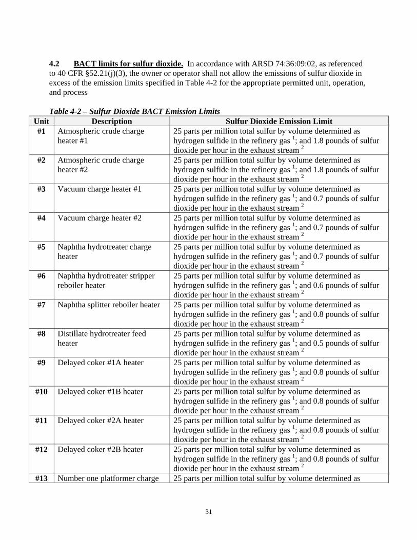
4.2 BACT limits for sulfur dioxide. In accordance with ARSD 74:36:09:02, as referenced to 40 CFR §52.21(j)(3), the owner or operator shall not allow the emissions of sulfur dioxide in excess of the emission limits specified in Table 4-2 for the appropriate permitted unit, operation, and process Table 4-2 – Sulfur Dioxide BACT Emission Limits
Unit Description Sulfur Dioxide Emission Limit #1 Atmospheric crude charge
heater #1 25 parts per million total sulfur by volume determined as hydrogen sulfide in the refinery gas 1; and 1.8 pounds of sulfur dioxide per hour in the exhaust stream 2
#2 Atmospheric crude charge heater #2
25 parts per million total sulfur by volume determined as hydrogen sulfide in the refinery gas 1; and 1.8 pounds of sulfur dioxide per hour in the exhaust stream 2
#3 Vacuum charge heater #1 25 parts per million total sulfur by volume determined as hydrogen sulfide in the refinery gas 1; and 0.7 pounds of sulfur dioxide per hour in the exhaust stream 2
#4 Vacuum charge heater #2 25 parts per million total sulfur by volume determined as hydrogen sulfide in the refinery gas 1; and 0.7 pounds of sulfur dioxide per hour in the exhaust stream 2
#5 Naphtha hydrotreater charge heater
25 parts per million total sulfur by volume determined as hydrogen sulfide in the refinery gas 1; and 0.7 pounds of sulfur dioxide per hour in the exhaust stream 2
#6 Naphtha hydrotreater stripper reboiler heater
25 parts per million total sulfur by volume determined as hydrogen sulfide in the refinery gas 1; and 0.6 pounds of sulfur dioxide per hour in the exhaust stream 2
#7 Naphtha splitter reboiler heater 25 parts per million total sulfur by volume determined as hydrogen sulfide in the refinery gas 1; and 0.8 pounds of sulfur dioxide per hour in the exhaust stream 2
#8 Distillate hydrotreater feed heater
25 parts per million total sulfur by volume determined as hydrogen sulfide in the refinery gas 1; and 0.5 pounds of sulfur dioxide per hour in the exhaust stream 2
#9 Delayed coker #1A heater 25 parts per million total sulfur by volume determined as hydrogen sulfide in the refinery gas 1; and 0.8 pounds of sulfur dioxide per hour in the exhaust stream 2
#10 Delayed coker #1B heater 25 parts per million total sulfur by volume determined as hydrogen sulfide in the refinery gas 1; and 0.8 pounds of sulfur dioxide per hour in the exhaust stream 2
#11 Delayed coker #2A heater 25 parts per million total sulfur by volume determined as hydrogen sulfide in the refinery gas 1; and 0.8 pounds of sulfur dioxide per hour in the exhaust stream 2
#12 Delayed coker #2B heater 25 parts per million total sulfur by volume determined as hydrogen sulfide in the refinery gas 1; and 0.8 pounds of sulfur dioxide per hour in the exhaust stream 2
#13 Number one platformer charge 25 parts per million total sulfur by volume determined as
31
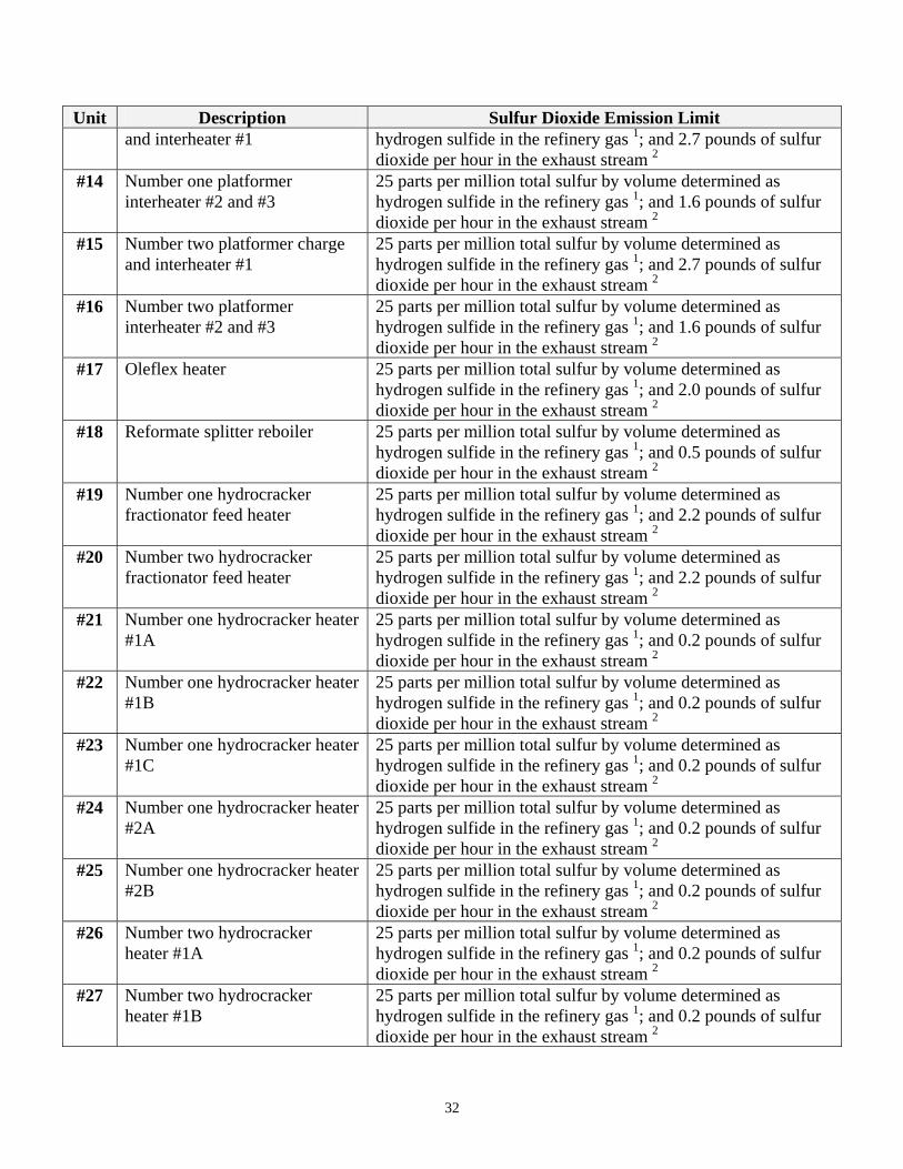
Unit Description Sulfur Dioxide Emission Limit and interheater #1 hydrogen sulfide in the refinery gas 1; and 2.7 pounds of sulfur
dioxide per hour in the exhaust stream 2
#14 Number one platformer interheater #2 and #3
25 parts per million total sulfur by volume determined as hydrogen sulfide in the refinery gas 1; and 1.6 pounds of sulfur dioxide per hour in the exhaust stream 2
#15 Number two platformer charge and interheater #1
25 parts per million total sulfur by volume determined as hydrogen sulfide in the refinery gas 1; and 2.7 pounds of sulfur dioxide per hour in the exhaust stream 2
#16 Number two platformer interheater #2 and #3
25 parts per million total sulfur by volume determined as hydrogen sulfide in the refinery gas 1; and 1.6 pounds of sulfur dioxide per hour in the exhaust stream 2
#17 Oleflex heater 25 parts per million total sulfur by volume determined as hydrogen sulfide in the refinery gas 1; and 2.0 pounds of sulfur dioxide per hour in the exhaust stream 2
#18 Reformate splitter reboiler 25 parts per million total sulfur by volume determined as hydrogen sulfide in the refinery gas 1; and 0.5 pounds of sulfur dioxide per hour in the exhaust stream 2
#19 Number one hydrocracker fractionator feed heater
25 parts per million total sulfur by volume determined as hydrogen sulfide in the refinery gas 1; and 2.2 pounds of sulfur dioxide per hour in the exhaust stream 2
#20 Number two hydrocracker fractionator feed heater
25 parts per million total sulfur by volume determined as hydrogen sulfide in the refinery gas 1; and 2.2 pounds of sulfur dioxide per hour in the exhaust stream 2
#21 Number one hydrocracker heater #1A
25 parts per million total sulfur by volume determined as hydrogen sulfide in the refinery gas 1; and 0.2 pounds of sulfur dioxide per hour in the exhaust stream 2
#22 Number one hydrocracker heater #1B
25 parts per million total sulfur by volume determined as hydrogen sulfide in the refinery gas 1; and 0.2 pounds of sulfur dioxide per hour in the exhaust stream 2
#23 Number one hydrocracker heater #1C
25 parts per million total sulfur by volume determined as hydrogen sulfide in the refinery gas 1; and 0.2 pounds of sulfur dioxide per hour in the exhaust stream 2
#24 Number one hydrocracker heater #2A
25 parts per million total sulfur by volume determined as hydrogen sulfide in the refinery gas 1; and 0.2 pounds of sulfur dioxide per hour in the exhaust stream 2
#25 Number one hydrocracker heater #2B
25 parts per million total sulfur by volume determined as hydrogen sulfide in the refinery gas 1; and 0.2 pounds of sulfur dioxide per hour in the exhaust stream 2
#26 Number two hydrocracker heater #1A
25 parts per million total sulfur by volume determined as hydrogen sulfide in the refinery gas 1; and 0.2 pounds of sulfur dioxide per hour in the exhaust stream 2
#27 Number two hydrocracker heater #1B
25 parts per million total sulfur by volume determined as hydrogen sulfide in the refinery gas 1; and 0.2 pounds of sulfur dioxide per hour in the exhaust stream 2
32
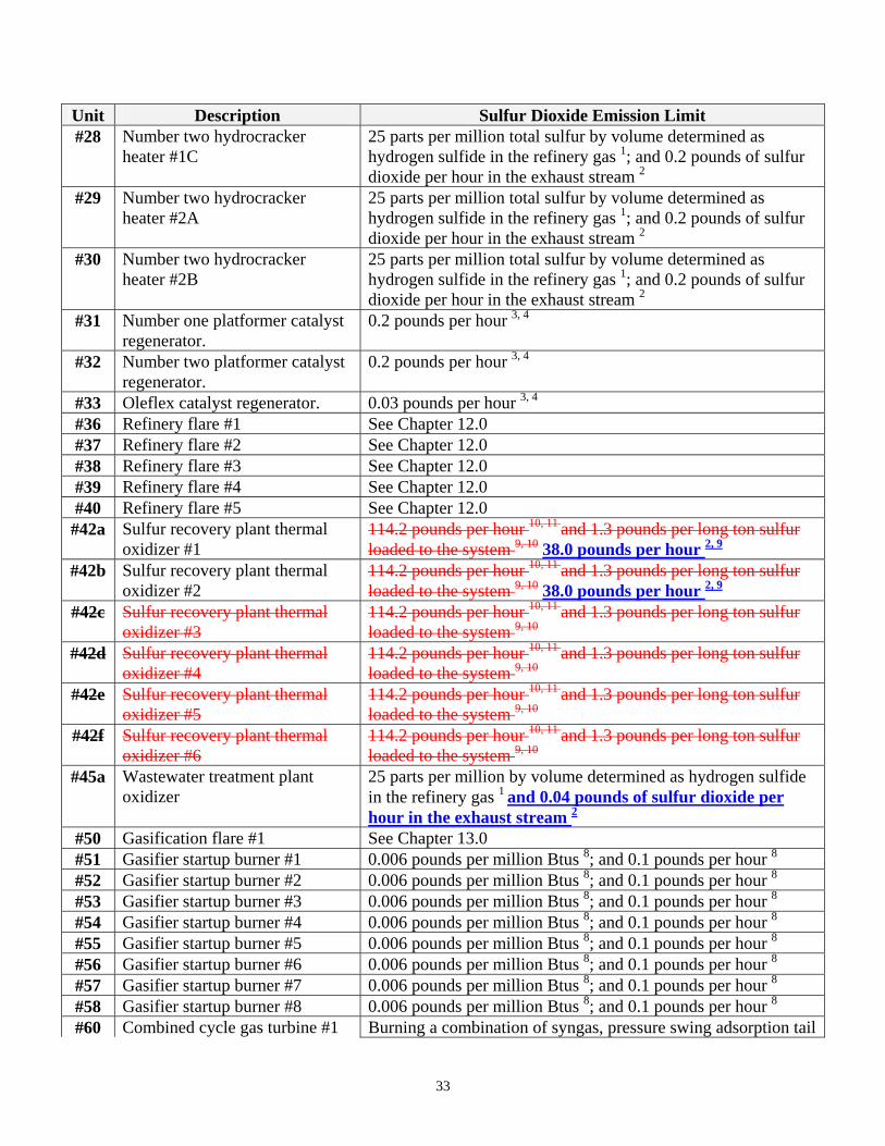
Unit Description Sulfur Dioxide Emission Limit #28 Number two hydrocracker
heater #1C 25 parts per million total sulfur by volume determined as hydrogen sulfide in the refinery gas 1; and 0.2 pounds of sulfur dioxide per hour in the exhaust stream 2
#29 Number two hydrocracker heater #2A
25 parts per million total sulfur by volume determined as hydrogen sulfide in the refinery gas 1; and 0.2 pounds of sulfur dioxide per hour in the exhaust stream 2
#30 Number two hydrocracker heater #2B
25 parts per million total sulfur by volume determined as hydrogen sulfide in the refinery gas 1; and 0.2 pounds of sulfur dioxide per hour in the exhaust stream 2
#31 Number one platformer catalyst regenerator.
0.2 pounds per hour 3, 4
#32 Number two platformer catalyst regenerator.
0.2 pounds per hour 3, 4
#33 Oleflex catalyst regenerator. 0.03 pounds per hour 3, 4
#36 Refinery flare #1 See Chapter 12.0 #37 Refinery flare #2 See Chapter 12.0 #38 Refinery flare #3 See Chapter 12.0 #39 Refinery flare #4 See Chapter 12.0 #40 Refinery flare #5 See Chapter 12.0 #42a Sulfur recovery plant thermal
oxidizer #1 114.2 pounds per hour 10, 11 and 1.3 pounds per long ton sulfur loaded to the system 9, 10 38.0 pounds per hour 2, 9
#42b Sulfur recovery plant thermal oxidizer #2
114.2 pounds per hour 10, 11 and 1.3 pounds per long ton sulfur loaded to the system 9, 10 38.0 pounds per hour 2, 9
#42c Sulfur recovery plant thermal oxidizer #3
114.2 pounds per hour 10, 11 and 1.3 pounds per long ton sulfur loaded to the system 9, 10
#42d Sulfur recovery plant thermal oxidizer #4
114.2 pounds per hour 10, 11 and 1.3 pounds per long ton sulfur loaded to the system 9, 10
#42e Sulfur recovery plant thermal oxidizer #5
114.2 pounds per hour 10, 11 and 1.3 pounds per long ton sulfur loaded to the system 9, 10
#42f Sulfur recovery plant thermal oxidizer #6
114.2 pounds per hour 10, 11 and 1.3 pounds per long ton sulfur loaded to the system 9, 10
#45a Wastewater treatment plant oxidizer
25 parts per million by volume determined as hydrogen sulfide in the refinery gas 1 and 0.04 pounds of sulfur dioxide per hour in the exhaust stream 2
#50 Gasification flare #1 See Chapter 13.0 #51 Gasifier startup burner #1 0.006 pounds per million Btus 8; and 0.1 pounds per hour 8
#52 Gasifier startup burner #2 0.006 pounds per million Btus 8; and 0.1 pounds per hour 8
#53 Gasifier startup burner #3 0.006 pounds per million Btus 8; and 0.1 pounds per hour 8
#54 Gasifier startup burner #4 0.006 pounds per million Btus 8; and 0.1 pounds per hour 8
#55 Gasifier startup burner #5 0.006 pounds per million Btus 8; and 0.1 pounds per hour 8
#56 Gasifier startup burner #6 0.006 pounds per million Btus 8; and 0.1 pounds per hour 8
#57 Gasifier startup burner #7 0.006 pounds per million Btus 8; and 0.1 pounds per hour 8
#58 Gasifier startup burner #8 0.006 pounds per million Btus 8; and 0.1 pounds per hour 8
#60 Combined cycle gas turbine #1 Burning a combination of syngas, pressure swing adsorption tail
33
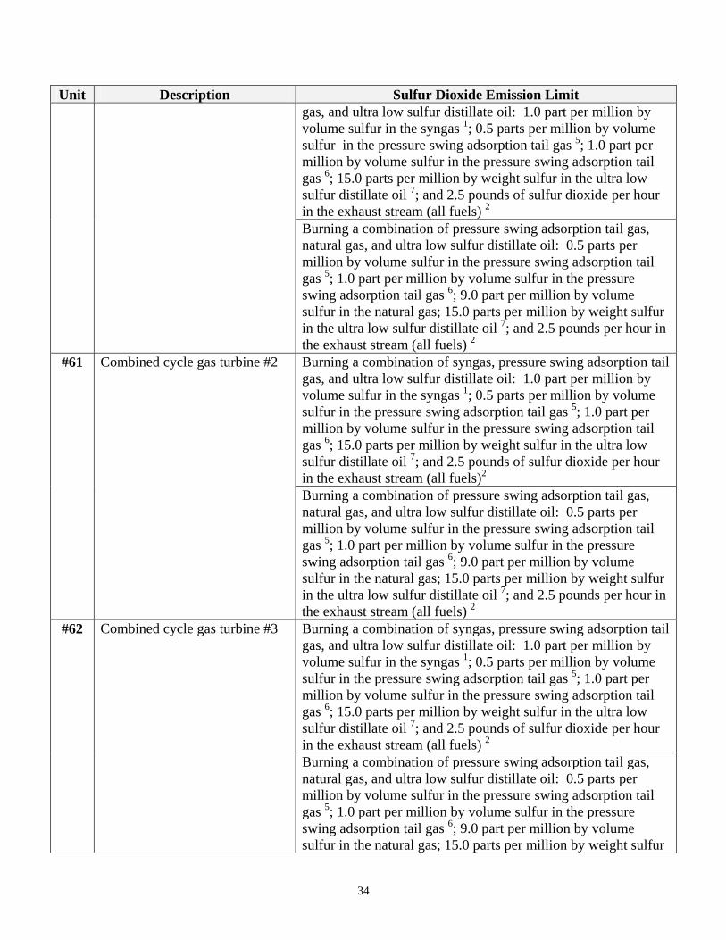
Unit Description Sulfur Dioxide Emission Limit gas, and ultra low sulfur distillate oil: 1.0 part per million by volume sulfur in the syngas 1; 0.5 parts per million by volume sulfur in the pressure swing adsorption tail gas 5; 1.0 part per million by volume sulfur in the pressure swing adsorption tail gas 6; 15.0 parts per million by weight sulfur in the ultra low sulfur distillate oil 7; and 2.5 pounds of sulfur dioxide per hour in the exhaust stream (all fuels) 2
Burning a combination of pressure swing adsorption tail gas, natural gas, and ultra low sulfur distillate oil: 0.5 parts per million by volume sulfur in the pressure swing adsorption tail gas 5; 1.0 part per million by volume sulfur in the pressure swing adsorption tail gas 6; 9.0 part per million by volume sulfur in the natural gas; 15.0 parts per million by weight sulfur in the ultra low sulfur distillate oil 7; and 2.5 pounds per hour in the exhaust stream (all fuels) 2
#61 Combined cycle gas turbine #2 Burning a combination of syngas, pressure swing adsorption tail gas, and ultra low sulfur distillate oil: 1.0 part per million by volume sulfur in the syngas 1; 0.5 parts per million by volume sulfur in the pressure swing adsorption tail gas 5; 1.0 part per million by volume sulfur in the pressure swing adsorption tail gas 6; 15.0 parts per million by weight sulfur in the ultra low sulfur distillate oil 7; and 2.5 pounds of sulfur dioxide per hour in the exhaust stream (all fuels)2
Burning a combination of pressure swing adsorption tail gas, natural gas, and ultra low sulfur distillate oil: 0.5 parts per million by volume sulfur in the pressure swing adsorption tail gas 5; 1.0 part per million by volume sulfur in the pressure swing adsorption tail gas 6; 9.0 part per million by volume sulfur in the natural gas; 15.0 parts per million by weight sulfur in the ultra low sulfur distillate oil 7; and 2.5 pounds per hour in the exhaust stream (all fuels) 2
#62 Combined cycle gas turbine #3 Burning a combination of syngas, pressure swing adsorption tail gas, and ultra low sulfur distillate oil: 1.0 part per million by volume sulfur in the syngas 1; 0.5 parts per million by volume sulfur in the pressure swing adsorption tail gas 5; 1.0 part per million by volume sulfur in the pressure swing adsorption tail gas 6; 15.0 parts per million by weight sulfur in the ultra low sulfur distillate oil 7; and 2.5 pounds of sulfur dioxide per hour in the exhaust stream (all fuels) 2
Burning a combination of pressure swing adsorption tail gas, natural gas, and ultra low sulfur distillate oil: 0.5 parts per million by volume sulfur in the pressure swing adsorption tail gas 5; 1.0 part per million by volume sulfur in the pressure swing adsorption tail gas 6; 9.0 part per million by volume sulfur in the natural gas; 15.0 parts per million by weight sulfur
34
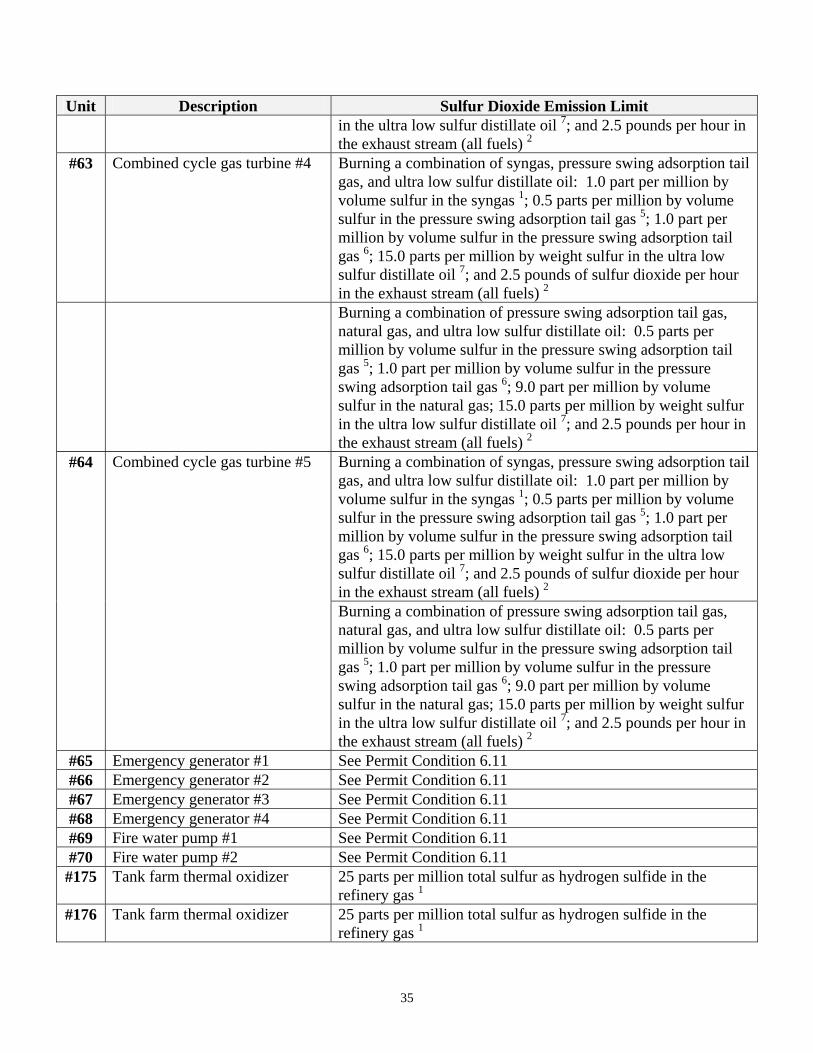
Unit Description Sulfur Dioxide Emission Limit in the ultra low sulfur distillate oil 7; and 2.5 pounds per hour in the exhaust stream (all fuels) 2
#63 Combined cycle gas turbine #4 Burning a combination of syngas, pressure swing adsorption tail gas, and ultra low sulfur distillate oil: 1.0 part per million by volume sulfur in the syngas 1; 0.5 parts per million by volume sulfur in the pressure swing adsorption tail gas 5; 1.0 part per million by volume sulfur in the pressure swing adsorption tail gas 6; 15.0 parts per million by weight sulfur in the ultra low sulfur distillate oil 7; and 2.5 pounds of sulfur dioxide per hour in the exhaust stream (all fuels) 2
Burning a combination of pressure swing adsorption tail gas, natural gas, and ultra low sulfur distillate oil: 0.5 parts per million by volume sulfur in the pressure swing adsorption tail gas 5; 1.0 part per million by volume sulfur in the pressure swing adsorption tail gas 6; 9.0 part per million by volume sulfur in the natural gas; 15.0 parts per million by weight sulfur in the ultra low sulfur distillate oil 7; and 2.5 pounds per hour in the exhaust stream (all fuels) 2
#64 Combined cycle gas turbine #5 Burning a combination of syngas, pressure swing adsorption tail gas, and ultra low sulfur distillate oil: 1.0 part per million by volume sulfur in the syngas 1; 0.5 parts per million by volume sulfur in the pressure swing adsorption tail gas 5; 1.0 part per million by volume sulfur in the pressure swing adsorption tail gas 6; 15.0 parts per million by weight sulfur in the ultra low sulfur distillate oil 7; and 2.5 pounds of sulfur dioxide per hour in the exhaust stream (all fuels) 2
Burning a combination of pressure swing adsorption tail gas, natural gas, and ultra low sulfur distillate oil: 0.5 parts per million by volume sulfur in the pressure swing adsorption tail gas 5; 1.0 part per million by volume sulfur in the pressure swing adsorption tail gas 6; 9.0 part per million by volume sulfur in the natural gas; 15.0 parts per million by weight sulfur in the ultra low sulfur distillate oil 7; and 2.5 pounds per hour in the exhaust stream (all fuels) 2
#65 Emergency generator #1 See Permit Condition 6.11 #66 Emergency generator #2 See Permit Condition 6.11 #67 Emergency generator #3 See Permit Condition 6.11 #68 Emergency generator #4 See Permit Condition 6.11 #69 Fire water pump #1 See Permit Condition 6.11 #70 Fire water pump #2 See Permit Condition 6.11 #175 Tank farm thermal oxidizer 25 parts per million total sulfur as hydrogen sulfide in the
refinery gas 1 #176 Tank farm thermal oxidizer 25 parts per million total sulfur as hydrogen sulfide in the
refinery gas 1
35
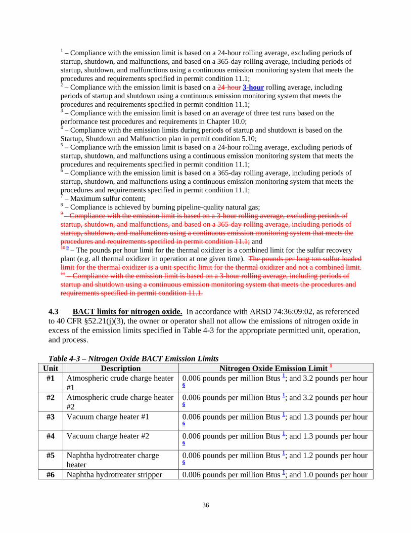
1 – Compliance with the emission limit is based on a 24-hour rolling average, excluding periods of startup, shutdown, and malfunctions, and based on a 365-day rolling average, including periods of startup, shutdown, and malfunctions using a continuous emission monitoring system that meets the procedures and requirements specified in permit condition 11.1; 2 – Compliance with the emission limit is based on a 24-hour 3-hour rolling average, including periods of startup and shutdown using a continuous emission monitoring system that meets the procedures and requirements specified in permit condition 11.1; 3 – Compliance with the emission limit is based on an average of three test runs based on the performance test procedures and requirements in Chapter 10.0; 4 – Compliance with the emission limits during periods of startup and shutdown is based on the Startup, Shutdown and Malfunction plan in permit condition 5.10; 5 – Compliance with the emission limit is based on a 24-hour rolling average, excluding periods of startup, shutdown, and malfunctions using a continuous emission monitoring system that meets the procedures and requirements specified in permit condition 11.1; 6 – Compliance with the emission limit is based on a 365-day rolling average, including periods of startup, shutdown, and malfunctions using a continuous emission monitoring system that meets the procedures and requirements specified in permit condition 11.1; 7 – Maximum sulfur content; 8 – Compliance is achieved by burning pipeline-quality natural gas; 9 – Compliance with the emission limit is based on a 3-hour rolling average, excluding periods of startup, shutdown, and malfunctions, and based on a 365-day rolling average, including periods of startup, shutdown, and malfunctions using a continuous emission monitoring system that meets the procedures and requirements specified in permit condition 11.1; and 10 9 – The pounds per hour limit for the thermal oxidizer is a combined limit for the sulfur recovery plant (e.g. all thermal oxidizer in operation at one given time). The pounds per long ton sulfur loaded limit for the thermal oxidizer is a unit specific limit for the thermal oxidizer and not a combined limit. 11 – Compliance with the emission limit is based on a 3-hour rolling average, including periods of startup and shutdown using a continuous emission monitoring system that meets the procedures and requirements specified in permit condition 11.1.
4.3 BACT limits for nitrogen oxide. In accordance with ARSD 74:36:09:02, as referenced to 40 CFR §52.21(j)(3), the owner or operator shall not allow the emissions of nitrogen oxide in excess of the emission limits specified in Table 4-3 for the appropriate permitted unit, operation, and process. Table 4-3 – Nitrogen Oxide BACT Emission Limits
Unit Description Nitrogen Oxide Emission Limit 1
#1 Atmospheric crude charge heater #1
0.006 pounds per million Btus 1; and 3.2 pounds per hour 6
#2 Atmospheric crude charge heater #2
0.006 pounds per million Btus 1; and 3.2 pounds per hour 6
#3 Vacuum charge heater #1 0.006 pounds per million Btus 1; and 1.3 pounds per hour 6
#4 Vacuum charge heater #2 0.006 pounds per million Btus 1; and 1.3 pounds per hour 6
#5 Naphtha hydrotreater charge heater
0.006 pounds per million Btus 1; and 1.2 pounds per hour 6
#6 Naphtha hydrotreater stripper 0.006 pounds per million Btus 1; and 1.0 pounds per hour
36
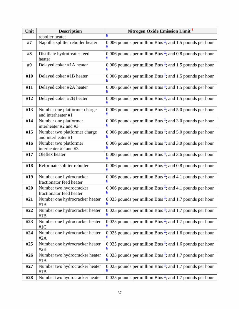
Unit Description Nitrogen Oxide Emission Limit 1
reboiler heater 6 #7 Naphtha splitter reboiler heater 0.006 pounds per million Btus 1; and 1.5 pounds per hour
6 #8 Distillate hydrotreater feed
heater 0.006 pounds per million Btus 1; and 0.8 pounds per hour 6
#9 Delayed coker #1A heater 0.006 pounds per million Btus 1; and 1.5 pounds per hour 6
#10 Delayed coker #1B heater 0.006 pounds per million Btus 1; and 1.5 pounds per hour 6
#11 Delayed coker #2A heater 0.006 pounds per million Btus 1; and 1.5 pounds per hour 6
#12 Delayed coker #2B heater 0.006 pounds per million Btus 1; and 1.5 pounds per hour 6
#13 Number one platformer charge and interheater #1
0.006 pounds per million Btus 1; and 5.0 pounds per hour 6
#14 Number one platformer interheater #2 and #3
0.006 pounds per million Btus 1; and 3.0 pounds per hour 6
#15 Number two platformer charge and interheater #1
0.006 pounds per million Btus 1; and 5.0 pounds per hour 6
#16 Number two platformer interheater #2 and #3
0.006 pounds per million Btus 1; and 3.0 pounds per hour 6
#17 Oleflex heater 0.006 pounds per million Btus 1; and 3.6 pounds per hour 6
#18 Reformate splitter reboiler 0.006 pounds per million Btus 1; and 0.8 pounds per hour 6
#19 Number one hydrocracker fractionator feed heater
0.006 pounds per million Btus 1; and 4.1 pounds per hour 6
#20 Number two hydrocracker fractionator feed heater
0.006 pounds per million Btus 1; and 4.1 pounds per hour 6
#21 Number one hydrocracker heater #1A
0.025 pounds per million Btus 1; and 1.7 pounds per hour 6
#22 Number one hydrocracker heater #1B
0.025 pounds per million Btus 1; and 1.7 pounds per hour 6
#23 Number one hydrocracker heater #1C
0.025 pounds per million Btus 1; and 1.7 pounds per hour 6
#24 Number one hydrocracker heater #2A
0.025 pounds per million Btus 1; and 1.6 pounds per hour 6
#25 Number one hydrocracker heater #2B
0.025 pounds per million Btus 1; and 1.6 pounds per hour 6
#26 Number two hydrocracker heater #1A
0.025 pounds per million Btus 1; and 1.7 pounds per hour 6
#27 Number two hydrocracker heater #1B
0.025 pounds per million Btus 1; and 1.7 pounds per hour 6
#28 Number two hydrocracker heater 0.025 pounds per million Btus 1; and 1.7 pounds per hour
37
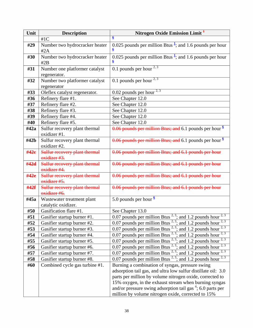
Unit Description Nitrogen Oxide Emission Limit 1
#1C 6 #29 Number two hydrocracker heater
#2A 0.025 pounds per million Btus 1; and 1.6 pounds per hour 6
#30 Number two hydrocracker heater #2B
0.025 pounds per million Btus 1; and 1.6 pounds per hour 6
#31 Number one platformer catalyst regenerator.
0.1 pounds per hour 2, 3
#32 Number two platformer catalyst regenerator
0.1 pounds per hour 2, 3
#33 Oleflex catalyst regenerator. 0.02 pounds per hour 2, 3
#36 Refinery flare #1. See Chapter 12.0 #37 Refinery flare #2. See Chapter 12.0 #38 Refinery flare #3. See Chapter 12.0 #39 Refinery flare #4. See Chapter 12.0 #40 Refinery flare #5. See Chapter 12.0 #42a Sulfur recovery plant thermal
oxidizer #1. 0.06 pounds per million Btus; and 6.1 pounds per hour 6
#42b Sulfur recovery plant thermal oxidizer #2.
0.06 pounds per million Btus; and 6.1 pounds per hour 6
#42c Sulfur recovery plant thermal oxidizer #3.
0.06 pounds per million Btus; and 6.1 pounds per hour
#42d Sulfur recovery plant thermal oxidizer #4.
0.06 pounds per million Btus; and 6.1 pounds per hour
#42e Sulfur recovery plant thermal oxidizer #5.
0.06 pounds per million Btus; and 6.1 pounds per hour
#42f Sulfur recovery plant thermal oxidizer #6.
0.06 pounds per million Btus; and 6.1 pounds per hour
#45a Wastewater treatment plant catalytic oxidizer.
5.0 pounds per hour 6
#50 Gasification flare #1. See Chapter 13.0 #51 Gasifier startup burner #1. 0.07 pounds per million Btus 2, 3; and 1.2 pounds hour 2, 3
#52 Gasifier startup burner #2. 0.07 pounds per million Btus 2, 3; and 1.2 pounds hour 2, 3
#53 Gasifier startup burner #3. 0.07 pounds per million Btus 2, 3; and 1.2 pounds hour 2, 3
#54 Gasifier startup burner #4. 0.07 pounds per million Btus 2, 3; and 1.2 pounds hour 2, 3
#55 Gasifier startup burner #5. 0.07 pounds per million Btus 2, 3; and 1.2 pounds hour 2, 3
#56 Gasifier startup burner #6. 0.07 pounds per million Btus 2, 3; and 1.2 pounds hour 2, 3
#57 Gasifier startup burner #7. 0.07 pounds per million Btus 2, 3; and 1.2 pounds hour 2, 3
#58 Gasifier startup burner #8. 0.07 pounds per million Btus 2, 3; and 1.2 pounds hour 2, 3
#60 Combined cycle gas turbine #1. Burning a combination of syngas, pressure swing adsorption tail gas, and ultra low sulfur distillate oil: 3.0 parts per million by volume nitrogen oxide, corrected to 15% oxygen, in the exhaust stream when burning syngas and/or pressure swing adsorption tail gas 4; 6.0 parts per million by volume nitrogen oxide, corrected to 15%
38
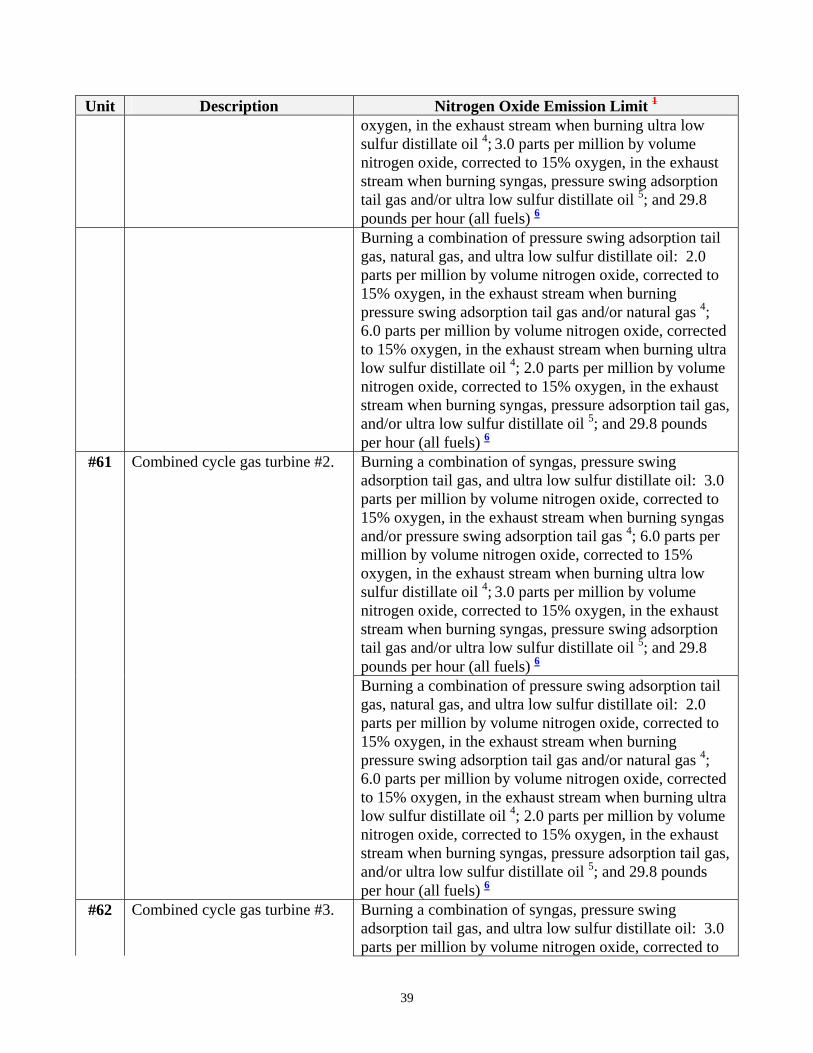
Unit Description Nitrogen Oxide Emission Limit 1
oxygen, in the exhaust stream when burning ultra low sulfur distillate oil 4; 3.0 parts per million by volume nitrogen oxide, corrected to 15% oxygen, in the exhaust stream when burning syngas, pressure swing adsorption tail gas and/or ultra low sulfur distillate oil 5; and 29.8 pounds per hour (all fuels) 6
Burning a combination of pressure swing adsorption tail gas, natural gas, and ultra low sulfur distillate oil: 2.0 parts per million by volume nitrogen oxide, corrected to 15% oxygen, in the exhaust stream when burning pressure swing adsorption tail gas and/or natural gas 4; 6.0 parts per million by volume nitrogen oxide, corrected to 15% oxygen, in the exhaust stream when burning ultra low sulfur distillate oil 4; 2.0 parts per million by volume nitrogen oxide, corrected to 15% oxygen, in the exhaust stream when burning syngas, pressure adsorption tail gas, and/or ultra low sulfur distillate oil 5; and 29.8 pounds per hour (all fuels) 6
#61 Combined cycle gas turbine #2. Burning a combination of syngas, pressure swing adsorption tail gas, and ultra low sulfur distillate oil: 3.0 parts per million by volume nitrogen oxide, corrected to 15% oxygen, in the exhaust stream when burning syngas and/or pressure swing adsorption tail gas 4; 6.0 parts per million by volume nitrogen oxide, corrected to 15% oxygen, in the exhaust stream when burning ultra low sulfur distillate oil 4; 3.0 parts per million by volume nitrogen oxide, corrected to 15% oxygen, in the exhaust stream when burning syngas, pressure swing adsorption tail gas and/or ultra low sulfur distillate oil 5; and 29.8 pounds per hour (all fuels) 6
Burning a combination of pressure swing adsorption tail gas, natural gas, and ultra low sulfur distillate oil: 2.0 parts per million by volume nitrogen oxide, corrected to 15% oxygen, in the exhaust stream when burning pressure swing adsorption tail gas and/or natural gas 4; 6.0 parts per million by volume nitrogen oxide, corrected to 15% oxygen, in the exhaust stream when burning ultra low sulfur distillate oil 4; 2.0 parts per million by volume nitrogen oxide, corrected to 15% oxygen, in the exhaust stream when burning syngas, pressure adsorption tail gas, and/or ultra low sulfur distillate oil 5; and 29.8 pounds per hour (all fuels) 6
#62 Combined cycle gas turbine #3. Burning a combination of syngas, pressure swing adsorption tail gas, and ultra low sulfur distillate oil: 3.0 parts per million by volume nitrogen oxide, corrected to
39
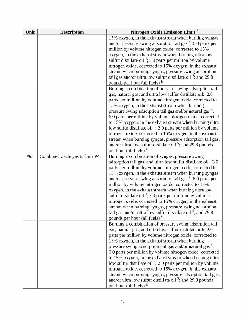
Unit Description Nitrogen Oxide Emission Limit 1
15% oxygen, in the exhaust stream when burning syngas and/or pressure swing adsorption tail gas 4; 6.0 parts per million by volume nitrogen oxide, corrected to 15% oxygen, in the exhaust stream when burning ultra low sulfur distillate oil 4; 3.0 parts per million by volume nitrogen oxide, corrected to 15% oxygen, in the exhaust stream when burning syngas, pressure swing adsorption tail gas and/or ultra low sulfur distillate oil 5; and 29.8 pounds per hour (all fuels) 6
Burning a combination of pressure swing adsorption tail gas, natural gas, and ultra low sulfur distillate oil: 2.0 parts per million by volume nitrogen oxide, corrected to 15% oxygen, in the exhaust stream when burning pressure swing adsorption tail gas and/or natural gas 4; 6.0 parts per million by volume nitrogen oxide, corrected to 15% oxygen, in the exhaust stream when burning ultra low sulfur distillate oil 4; 2.0 parts per million by volume nitrogen oxide, corrected to 15% oxygen, in the exhaust stream when burning syngas, pressure adsorption tail gas, and/or ultra low sulfur distillate oil 5; and 29.8 pounds per hour (all fuels) 6
#63 Combined cycle gas turbine #4. Burning a combination of syngas, pressure swing adsorption tail gas, and ultra low sulfur distillate oil: 3.0 parts per million by volume nitrogen oxide, corrected to 15% oxygen, in the exhaust stream when burning syngas and/or pressure swing adsorption tail gas 4; 6.0 parts per million by volume nitrogen oxide, corrected to 15% oxygen, in the exhaust stream when burning ultra low sulfur distillate oil 4; 3.0 parts per million by volume nitrogen oxide, corrected to 15% oxygen, in the exhaust stream when burning syngas, pressure swing adsorption tail gas and/or ultra low sulfur distillate oil 5; and 29.8 pounds per hour (all fuels) 6
Burning a combination of pressure swing adsorption tail gas, natural gas, and ultra low sulfur distillate oil: 2.0 parts per million by volume nitrogen oxide, corrected to 15% oxygen, in the exhaust stream when burning pressure swing adsorption tail gas and/or natural gas 4; 6.0 parts per million by volume nitrogen oxide, corrected to 15% oxygen, in the exhaust stream when burning ultra low sulfur distillate oil 4; 2.0 parts per million by volume nitrogen oxide, corrected to 15% oxygen, in the exhaust stream when burning syngas, pressure adsorption tail gas, and/or ultra low sulfur distillate oil 5; and 29.8 pounds per hour (all fuels) 6
40
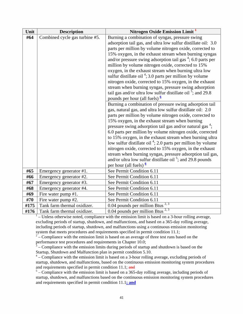
Unit Description Nitrogen Oxide Emission Limit 1
#64 Combined cycle gas turbine #5. Burning a combination of syngas, pressure swing adsorption tail gas, and ultra low sulfur distillate oil: 3.0 parts per million by volume nitrogen oxide, corrected to 15% oxygen, in the exhaust stream when burning syngas and/or pressure swing adsorption tail gas 4; 6.0 parts per million by volume nitrogen oxide, corrected to 15% oxygen, in the exhaust stream when burning ultra low sulfur distillate oil 4; 3.0 parts per million by volume nitrogen oxide, corrected to 15% oxygen, in the exhaust stream when burning syngas, pressure swing adsorption tail gas and/or ultra low sulfur distillate oil 5; and 29.8 pounds per hour (all fuels) 6
Burning a combination of pressure swing adsorption tail gas, natural gas, and ultra low sulfur distillate oil: 2.0 parts per million by volume nitrogen oxide, corrected to 15% oxygen, in the exhaust stream when burning pressure swing adsorption tail gas and/or natural gas 4; 6.0 parts per million by volume nitrogen oxide, corrected to 15% oxygen, in the exhaust stream when burning ultra low sulfur distillate oil 4; 2.0 parts per million by volume nitrogen oxide, corrected to 15% oxygen, in the exhaust stream when burning syngas, pressure adsorption tail gas, and/or ultra low sulfur distillate oil 5; and 29.8 pounds per hour (all fuels) 6
#65 Emergency generator #1. See Permit Condition 6.11 #66 Emergency generator #2. See Permit Condition 6.11 #67 Emergency generator #3. See Permit Condition 6.11 #68 Emergency generator #4. See Permit Condition 6.11 #69 Fire water pump #1. See Permit Condition 6.11 #70 Fire water pump #2. See Permit Condition 6.11 #175 Tank farm thermal oxidizer. 0.04 pounds per million Btus 2, 3
#176 Tank farm thermal oxidizer. 0.04 pounds per million Btus 2, 3
1 – Unless otherwise noted, compliance with the emission limit is based on a 3-hour rolling average, excluding periods of startup, shutdown, and malfunctions, and based on a 365-day rolling average, including periods of startup, shutdown, and malfunctions using a continuous emission monitoring system that meets procedures and requirements specified in permit condition 11.1; 2 – Compliance with the emission limit is based on an average of three test runs based on the performance test procedures and requirements in Chapter 10.0; 3 – Compliance with the emission limits during periods of startup and shutdown is based on the Startup, Shutdown and Malfunction plan in permit condition 5.10. 4 – Compliance with the emission limit is based on a 3-hour rolling average, excluding periods of startup, shutdown, and malfunctions, based on the continuous emission monitoring system procedures and requirements specified in permit condition 11.1; and 5 – Compliance with the emission limit is based on a 365-day rolling average, including periods of startup, shutdown, and malfunctions based on the continuous emission monitoring system procedures and requirements specified in permit condition 11.1; and
41
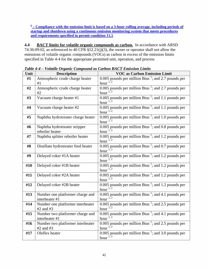
6 – Compliance with the emission limit is based on a 3-hour rolling average, including periods of startup and shutdown using a continuous emission monitoring system that meets procedures and requirements specified in permit condition 11.1.
4.4 BACT limits for volatile organic compounds as carbon. In accordance with ARSD 74:36:09:02, as referenced to 40 CFR §52.21(j)(3), the owner or operator shall not allow the emissions of volatile organic compounds (VOCs) as carbon in excess of the emission limits specified in Table 4-4 for the appropriate permitted unit, operation, and process Table 4-4 – Volatile Organic Compound as Carbon BACT Emission Limits Unit Description VOC as Carbon Emission Limit #1 Atmospheric crude charge heater
#1 0.005 pounds per million Btus 1; and 2.7 pounds per hour 1, 2
#2 Atmospheric crude charge heater #2
0.005 pounds per million Btus 1; and 2.7 pounds per hour 1, 2
#3 Vacuum charge heater #1 0.005 pounds per million Btus 1; and 1.1 pounds per hour 1, 2
#4 Vacuum charge heater #2 0.005 pounds per million Btus 1; and 1.1 pounds per hour 1, 2
#5 Naphtha hydrotreater charge heater 0.005 pounds per million Btus 1; and 1.0 pounds per hour 1, 2
#6 Naphtha hydrotreater stripper reboiler heater
0.005 pounds per million Btus 1; and 0.8 pounds per hour 1, 2
#7 Naphtha splitter reboiler heater 0.005 pounds per million Btus 1; and 1.2 pounds per hour 1, 2
#8 Distillate hydrotreater feed heater 0.005 pounds per million Btus 1; and 0.7 pounds per hour 1, 2
#9 Delayed coker #1A heater 0.005 pounds per million Btus 1; and 1.2 pounds per hour 1, 2
#10 Delayed coker #1B heater 0.005 pounds per million Btus 1; and 1.2 pounds per hour 1, 2
#11 Delayed coker #2A heater 0.005 pounds per million Btus 1; and 1.2 pounds per hour 1, 2
#12 Delayed coker #2B heater 0.005 pounds per million Btus 1; and 1.2 pounds per hour 1, 2
#13 Number one platformer charge and interheater #1
0.005 pounds per million Btus 1; and 4.1 pounds per hour 1, 2
#14 Number one platformer interheater #2 and #3
0.005 pounds per million Btus 1; and 2.5 pounds per hour 1, 2
#15 Number two platformer charge and interheater #1
0.005 pounds per million Btus 1; and 4.1 pounds per hour 1, 2
#16 Number two platformer interheater #2 and #3
0.005 pounds per million Btus 1; and 2.5 pounds per hour 1, 2
#17 Oleflex heater 0.005 pounds per million Btus 1; and 3.0 pounds per hour 1, 2
42
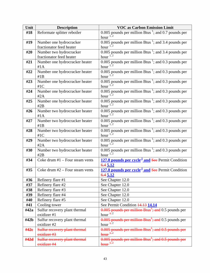
Unit Description VOC as Carbon Emission Limit #18 Reformate splitter reboiler 0.005 pounds per million Btus 1; and 0.7 pounds per
hour 1, 2
#19 Number one hydrocracker fractionator feed heater
0.005 pounds per million Btus 1; and 3.4 pounds per hour 1, 2
#20 Number two hydrocracker fractionator feed heater
0.005 pounds per million Btus 1; and 3.4 pounds per hour 1, 2
#21 Number one hydrocracker heater #1A
0.005 pounds per million Btus 1; and 0.3 pounds per hour 1, 2
#22 Number one hydrocracker heater #1B
0.005 pounds per million Btus 1; and 0.3 pounds per hour 1, 2
#23 Number one hydrocracker heater #1C
0.005 pounds per million Btus 1; and 0.3 pounds per hour 1, 2
#24 Number one hydrocracker heater #2A
0.005 pounds per million Btus 1; and 0.3 pounds per hour 1, 2
#25 Number one hydrocracker heater #2B
0.005 pounds per million Btus 1; and 0.3 pounds per hour 1, 2
#26 Number two hydrocracker heater #1A
0.005 pounds per million Btus 1; and 0.3 pounds per hour 1, 2
#27 Number two hydrocracker heater #1B
0.005 pounds per million Btus 1; and 0.3 pounds per hour 1, 2
#28 Number two hydrocracker heater #1C
0.005 pounds per million Btus 1; and 0.3 pounds per hour 1, 2
#29 Number two hydrocracker heater #2A
0.005 pounds per million Btus 1; and 0.3 pounds per hour 1, 2
#30 Number two hydrocracker heater #2B
0.005 pounds per million Btus 1; and 0.3 pounds per hour 1, 2
#34 Coke drum #1 – Four steam vents 127.8 pounds per cycle 1 and See Permit Condition 6.4 5.12
#35 Coke drum #2 – Four steam vents 127.8 pounds per cycle 1 and See Permit Condition 6.4 5.12
#36 Refinery flare #1 See Chapter 12.0 #37 Refinery flare #2 See Chapter 12.0 #38 Refinery flare #3 See Chapter 12.0 #39 Refinery flare #4 See Chapter 12.0 #40 Refinery flare #5 See Chapter 12.0 #41 Cooling tower See Permit Condition 14.13 14.14#42a Sulfur recovery plant thermal
oxidizer #1 0.005 pounds per million Btus1; and 0.5 pounds per hour 1, 2
#42b Sulfur recovery plant thermal oxidizer #2
0.005 pounds per million Btus1; and 0.5 pounds per hour 1, 2
#42c Sulfur recovery plant thermal oxidizer #3
0.005 pounds per million Btus1; and 0.5 pounds per hour 1, 2
#42d Sulfur recovery plant thermal oxidizer #4
0.005 pounds per million Btus1; and 0.5 pounds per hour 1, 2
43
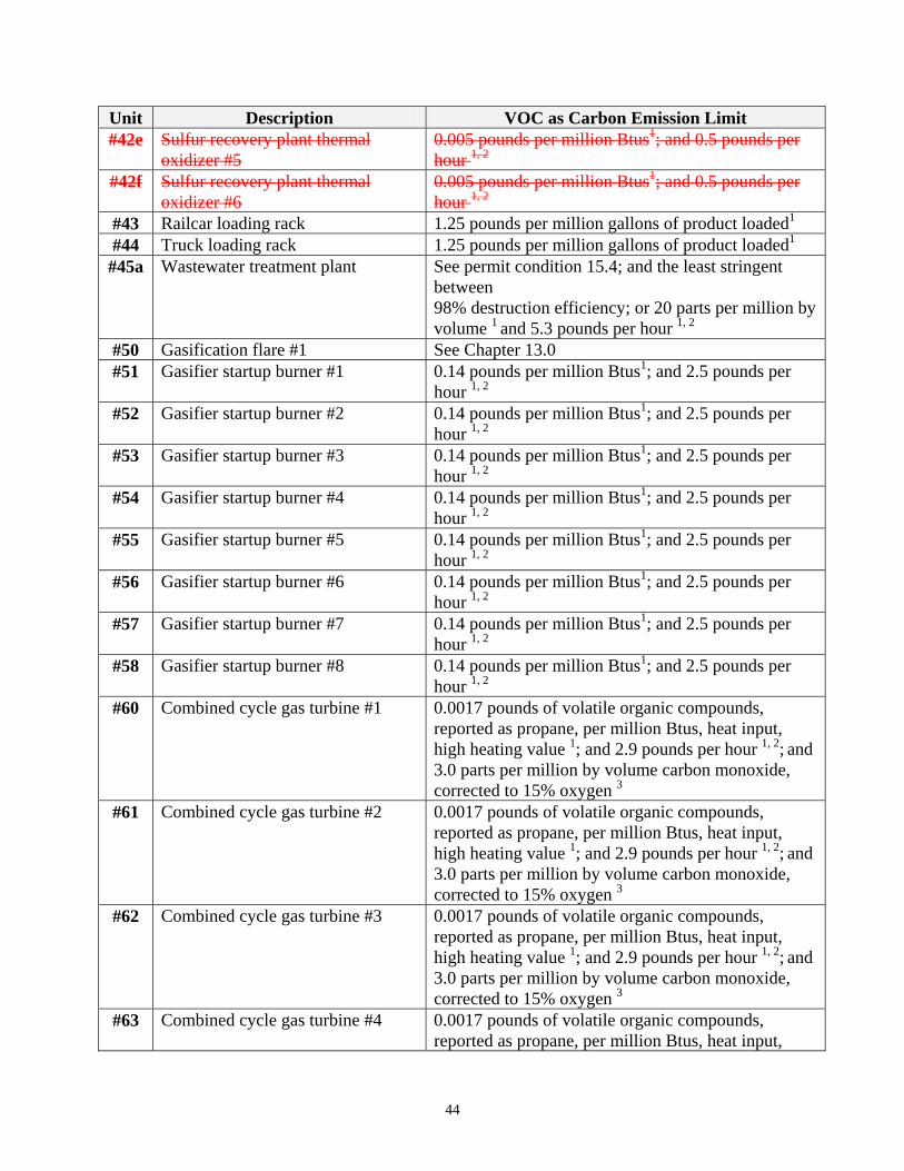
Unit Description VOC as Carbon Emission Limit #42e Sulfur recovery plant thermal
oxidizer #5 0.005 pounds per million Btus1; and 0.5 pounds per hour 1, 2
#42f Sulfur recovery plant thermal oxidizer #6
0.005 pounds per million Btus1; and 0.5 pounds per hour 1, 2
#43 Railcar loading rack 1.25 pounds per million gallons of product loaded1
#44 Truck loading rack 1.25 pounds per million gallons of product loaded1
#45a Wastewater treatment plant See permit condition 15.4; and the least stringent between 98% destruction efficiency; or 20 parts per million by volume 1 and 5.3 pounds per hour 1, 2
#50 Gasification flare #1 See Chapter 13.0 #51 Gasifier startup burner #1 0.14 pounds per million Btus1; and 2.5 pounds per
hour 1, 2
#52 Gasifier startup burner #2 0.14 pounds per million Btus1; and 2.5 pounds per hour 1, 2
#53 Gasifier startup burner #3 0.14 pounds per million Btus1; and 2.5 pounds per hour 1, 2
#54 Gasifier startup burner #4 0.14 pounds per million Btus1; and 2.5 pounds per hour 1, 2
#55 Gasifier startup burner #5 0.14 pounds per million Btus1; and 2.5 pounds per hour 1, 2
#56 Gasifier startup burner #6 0.14 pounds per million Btus1; and 2.5 pounds per hour 1, 2
#57 Gasifier startup burner #7 0.14 pounds per million Btus1; and 2.5 pounds per hour 1, 2
#58 Gasifier startup burner #8 0.14 pounds per million Btus1; and 2.5 pounds per hour 1, 2
#60 Combined cycle gas turbine #1 0.0017 pounds of volatile organic compounds, reported as propane, per million Btus, heat input, high heating value 1; and 2.9 pounds per hour 1, 2; and 3.0 parts per million by volume carbon monoxide, corrected to 15% oxygen 3
#61 Combined cycle gas turbine #2 0.0017 pounds of volatile organic compounds, reported as propane, per million Btus, heat input, high heating value 1; and 2.9 pounds per hour 1, 2; and 3.0 parts per million by volume carbon monoxide, corrected to 15% oxygen 3
#62 Combined cycle gas turbine #3 0.0017 pounds of volatile organic compounds, reported as propane, per million Btus, heat input, high heating value 1; and 2.9 pounds per hour 1, 2; and 3.0 parts per million by volume carbon monoxide, corrected to 15% oxygen 3
#63 Combined cycle gas turbine #4 0.0017 pounds of volatile organic compounds, reported as propane, per million Btus, heat input,
44
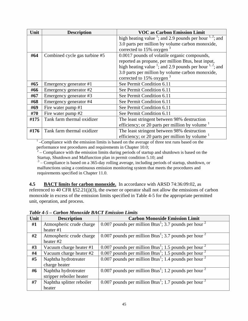
Unit Description VOC as Carbon Emission Limit high heating value 1; and 2.9 pounds per hour 1, 2; and 3.0 parts per million by volume carbon monoxide, corrected to 15% oxygen 3
#64 Combined cycle gas turbine #5 0.0017 pounds of volatile organic compounds, reported as propane, per million Btus, heat input, high heating value 1; and 2.9 pounds per hour 1, 2; and 3.0 parts per million by volume carbon monoxide, corrected to 15% oxygen 3
#65 Emergency generator #1 See Permit Condition 6.11 #66 Emergency generator #2 See Permit Condition 6.11 #67 Emergency generator #3 See Permit Condition 6.11 #68 Emergency generator #4 See Permit Condition 6.11 #69 Fire water pump #1 See Permit Condition 6.11 #70 Fire water pump #2 See Permit Condition 6.11 #175 Tank farm thermal oxidizer The least stringent between 98% destruction
efficiency; or 20 parts per million by volume 1
#176 Tank farm thermal oxidizer The least stringent between 98% destruction efficiency; or 20 parts per million by volume 1
1 –Compliance with the emission limits is based on the average of three test runs based on the performance test procedures and requirements in Chapter 10.0; 2 – Compliance with the emission limits during periods of startup and shutdown is based on the Startup, Shutdown and Malfunction plan in permit condition 5.10; and 3 – Compliance is based on a 365-day rolling average, including periods of startup, shutdown, or malfunctions using a continuous emission monitoring system that meets the procedures and requirements specified in Chapter 11.0.
4.5 BACT limits for carbon monoxide. In accordance with ARSD 74:36:09:02, as referenced to 40 CFR §52.21(j)(3), the owner or operator shall not allow the emissions of carbon monoxide in excess of the emission limits specified in Table 4-5 for the appropriate permitted unit, operation, and process.
Table 4-5 – Carbon Monoxide BACT Emission Limits Unit Description Carbon Monoxide Emission Limit #1 Atmospheric crude charge
heater #1 0.007 pounds per million Btus1; 3.7 pounds per hour 2
#2 Atmospheric crude charge heater #2
0.007 pounds per million Btus1; 3.7 pounds per hour 2
#3 Vacuum charge heater #1 0.007 pounds per million Btus1; 1.5 pounds per hour 2
#4 Vacuum charge heater #2 0.007 pounds per million Btus1; 1.5 pounds per hour 2
#5 Naphtha hydrotreater charge heater
0.007 pounds per million Btus1; 1.4 pounds per hour 2
#6 Naphtha hydrotreater stripper reboiler heater
0.007 pounds per million Btus1; 1.2 pounds per hour 2
#7 Naphtha splitter reboiler heater
0.007 pounds per million Btus1; 1.7 pounds per hour 2
45
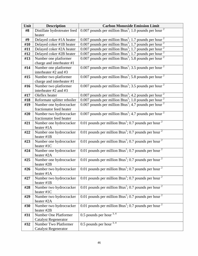
Unit Description Carbon Monoxide Emission Limit #8 Distillate hydrotreater feed
heater 0.007 pounds per million Btus1; 1.0 pounds per hour 2
#9 Delayed coker #1A heater 0.007 pounds per million Btus1; 1.7 pounds per hour 2
#10 Delayed coker #1B heater 0.007 pounds per million Btus1; 1.7 pounds per hour 2
#11 Delayed coker #2A heater 0.007 pounds per million Btus1; 1.7 pounds per hour 2
#12 Delayed coker #2B heater 0.007 pounds per million Btus1; 1.7 pounds per hour 2
#13 Number one platformer charge and interheater #1
0.007 pounds per million Btus1; 5.8 pounds per hour 2
#14 Number one platformer interheater #2 and #3
0.007 pounds per million Btus1; 3.5 pounds per hour 2
#15 Number two platformer charge and interheater #1
0.007 pounds per million Btus1; 5.8 pounds per hour 2
#16 Number two platformer interheater #2 and #3
0.007 pounds per million Btus1; 3.5 pounds per hour 2
#17 Oleflex heater 0.007 pounds per million Btus1; 4.2 pounds per hour 2
#18 Reformate splitter reboiler 0.007 pounds per million Btus1; 1.0 pounds per hour 2
#19 Number one hydrocracker fractionator feed heater
0.007 pounds per million Btus1; 4.7 pounds per hour 2
#20 Number two hydrocracker fractionator feed heater
0.007 pounds per million Btus1; 4.7 pounds per hour 2
#21 Number one hydrocracker heater #1A
0.01 pounds per million Btus1; 0.7 pounds per hour 2
#22 Number one hydrocracker heater #1B
0.01 pounds per million Btus1; 0.7 pounds per hour 2
#23 Number one hydrocracker heater #1C
0.01 pounds per million Btus1; 0.7 pounds per hour 2
#24 Number one hydrocracker heater #2A
0.01 pounds per million Btus1; 0.7 pounds per hour 2
#25 Number one hydrocracker heater #2B
0.01 pounds per million Btus1; 0.7 pounds per hour 2
#26 Number two hydrocracker heater #1A
0.01 pounds per million Btus1; 0.7 pounds per hour 2
#27 Number two hydrocracker heater #1B
0.01 pounds per million Btus1; 0.7 pounds per hour 2
#28 Number two hydrocracker heater #1C
0.01 pounds per million Btus1; 0.7 pounds per hour 2
#29 Number two hydrocracker heater #2A
0.01 pounds per million Btus1; 0.7 pounds per hour 2
#30 Number two hydrocracker heater #2B
0.01 pounds per million Btus1; 0.7 pounds per hour 2
#31 Number One Platformer Catalyst Regenerator
0.5 pounds per hour 3, 4
#32 Number Two Platformer Catalyst Regenerator
0.5 pounds per hour 3, 4
46
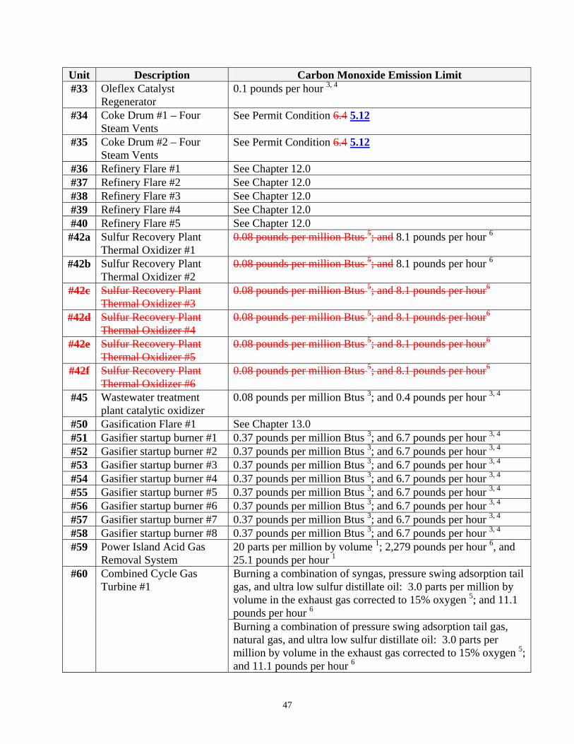
Unit Description Carbon Monoxide Emission Limit #33 Oleflex Catalyst
Regenerator 0.1 pounds per hour 3, 4
#34 Coke Drum #1 – Four Steam Vents
See Permit Condition 6.4 5.12
#35 Coke Drum #2 – Four Steam Vents
See Permit Condition 6.4 5.12
#36 Refinery Flare #1 See Chapter 12.0 #37 Refinery Flare #2 See Chapter 12.0 #38 Refinery Flare #3 See Chapter 12.0 #39 Refinery Flare #4 See Chapter 12.0 #40 Refinery Flare #5 See Chapter 12.0 #42a Sulfur Recovery Plant
Thermal Oxidizer #1 0.08 pounds per million Btus 5; and 8.1 pounds per hour 6
#42b Sulfur Recovery Plant Thermal Oxidizer #2
0.08 pounds per million Btus 5; and 8.1 pounds per hour 6
#42c Sulfur Recovery Plant Thermal Oxidizer #3
0.08 pounds per million Btus 5; and 8.1 pounds per hour6
#42d Sulfur Recovery Plant Thermal Oxidizer #4
0.08 pounds per million Btus 5; and 8.1 pounds per hour6
#42e Sulfur Recovery Plant Thermal Oxidizer #5
0.08 pounds per million Btus 5; and 8.1 pounds per hour6
#42f Sulfur Recovery Plant Thermal Oxidizer #6
0.08 pounds per million Btus 5; and 8.1 pounds per hour6
#45 Wastewater treatment plant catalytic oxidizer
0.08 pounds per million Btus 3; and 0.4 pounds per hour 3, 4
#50 Gasification Flare #1 See Chapter 13.0 #51 Gasifier startup burner #1 0.37 pounds per million Btus 3; and 6.7 pounds per hour 3, 4
#52 Gasifier startup burner #2 0.37 pounds per million Btus 3; and 6.7 pounds per hour 3, 4
#53 Gasifier startup burner #3 0.37 pounds per million Btus 3; and 6.7 pounds per hour 3, 4
#54 Gasifier startup burner #4 0.37 pounds per million Btus 3; and 6.7 pounds per hour 3, 4
#55 Gasifier startup burner #5 0.37 pounds per million Btus 3; and 6.7 pounds per hour 3, 4
#56 Gasifier startup burner #6 0.37 pounds per million Btus 3; and 6.7 pounds per hour 3, 4
#57 Gasifier startup burner #7 0.37 pounds per million Btus 3; and 6.7 pounds per hour 3, 4
#58 Gasifier startup burner #8 0.37 pounds per million Btus 3; and 6.7 pounds per hour 3, 4
#59 Power Island Acid Gas Removal System
20 parts per million by volume 1; 2,279 pounds per hour 6, and 25.1 pounds per hour 1
#60 Combined Cycle Gas Turbine #1
Burning a combination of syngas, pressure swing adsorption tail gas, and ultra low sulfur distillate oil: 3.0 parts per million by volume in the exhaust gas corrected to 15% oxygen 5; and 11.1 pounds per hour 6
Burning a combination of pressure swing adsorption tail gas, natural gas, and ultra low sulfur distillate oil: 3.0 parts per million by volume in the exhaust gas corrected to 15% oxygen 5; and 11.1 pounds per hour 6
47
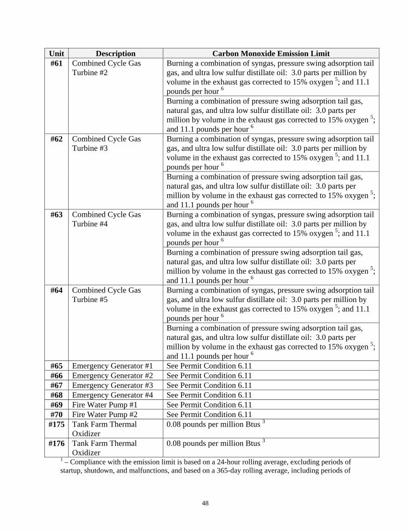
Unit Description Carbon Monoxide Emission Limit #61 Combined Cycle Gas
Turbine #2 Burning a combination of syngas, pressure swing adsorption tail gas, and ultra low sulfur distillate oil: 3.0 parts per million by volume in the exhaust gas corrected to 15% oxygen 5; and 11.1 pounds per hour 6
Burning a combination of pressure swing adsorption tail gas, natural gas, and ultra low sulfur distillate oil: 3.0 parts per million by volume in the exhaust gas corrected to 15% oxygen 5; and 11.1 pounds per hour 6
#62 Combined Cycle Gas Turbine #3
Burning a combination of syngas, pressure swing adsorption tail gas, and ultra low sulfur distillate oil: 3.0 parts per million by volume in the exhaust gas corrected to 15% oxygen 5; and 11.1 pounds per hour 6
Burning a combination of pressure swing adsorption tail gas, natural gas, and ultra low sulfur distillate oil: 3.0 parts per million by volume in the exhaust gas corrected to 15% oxygen 5; and 11.1 pounds per hour 6
#63 Combined Cycle Gas Turbine #4
Burning a combination of syngas, pressure swing adsorption tail gas, and ultra low sulfur distillate oil: 3.0 parts per million by volume in the exhaust gas corrected to 15% oxygen 5; and 11.1 pounds per hour 6
Burning a combination of pressure swing adsorption tail gas, natural gas, and ultra low sulfur distillate oil: 3.0 parts per million by volume in the exhaust gas corrected to 15% oxygen 5; and 11.1 pounds per hour 6
#64 Combined Cycle Gas Turbine #5
Burning a combination of syngas, pressure swing adsorption tail gas, and ultra low sulfur distillate oil: 3.0 parts per million by volume in the exhaust gas corrected to 15% oxygen 5; and 11.1 pounds per hour 6
Burning a combination of pressure swing adsorption tail gas, natural gas, and ultra low sulfur distillate oil: 3.0 parts per million by volume in the exhaust gas corrected to 15% oxygen 5; and 11.1 pounds per hour 6
#65 Emergency Generator #1 See Permit Condition 6.11 #66 Emergency Generator #2 See Permit Condition 6.11 #67 Emergency Generator #3 See Permit Condition 6.11 #68 Emergency Generator #4 See Permit Condition 6.11 #69 Fire Water Pump #1 See Permit Condition 6.11 #70 Fire Water Pump #2 See Permit Condition 6.11 #175 Tank Farm Thermal
Oxidizer 0.08 pounds per million Btus 3
#176 Tank Farm Thermal Oxidizer
0.08 pounds per million Btus 3
1 – Compliance with the emission limit is based on a 24-hour rolling average, excluding periods of startup, shutdown, and malfunctions, and based on a 365-day rolling average, including periods of
48
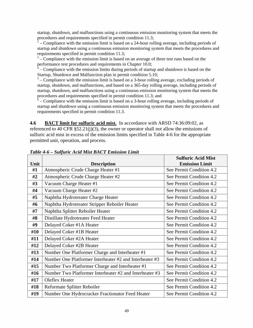
startup, shutdown, and malfunctions using a continuous emission monitoring system that meets the procedures and requirements specified in permit condition 11.3; 2 – Compliance with the emission limit is based on a 24-hour rolling average, including periods of startup and shutdown using a continuous emission monitoring system that meets the procedures and requirements specified in permit condition 11.3;
3 – Compliance with the emission limit is based on an average of three test runs based on the performance test procedures and requirements in Chapter 10.0; 4 – Compliance with the emission limits during periods of startup and shutdown is based on the Startup, Shutdown and Malfunction plan in permit condition 5.10; 5 – Compliance with the emission limit is based on a 3-hour rolling average, excluding periods of startup, shutdown, and malfunctions, and based on a 365-day rolling average, including periods of startup, shutdown, and malfunctions using a continuous emission monitoring system that meets the procedures and requirements specified in permit condition 11.3; and 6 – Compliance with the emission limit is based on a 3-hour rolling average, including periods of startup and shutdown using a continuous emission monitoring system that meets the procedures and requirements specified in permit condition 11.3.
4.6 BACT limit for sulfuric acid mist. In accordance with ARSD 74:36:09:02, as referenced to 40 CFR §52.21(j)(3), the owner or operator shall not allow the emissions of sulfuric acid mist in excess of the emission limits specified in Table 4-6 for the appropriate permitted unit, operation, and process.
Table 4-6 – Sulfuric Acid Mist BACT Emission Limit
Unit
Description
Sulfuric Acid Mist Emission Limit
#1 Atmospheric Crude Charge Heater #1 See Permit Condition 4.2 #2 Atmospheric Crude Charge Heater #2 See Permit Condition 4.2 #3 Vacuum Charge Heater #1 See Permit Condition 4.2 #4 Vacuum Charge Heater #2 See Permit Condition 4.2 #5 Naphtha Hydrotreater Charge Heater See Permit Condition 4.2 #6 Naphtha Hydrotreater Stripper Reboiler Heater See Permit Condition 4.2 #7 Naphtha Splitter Reboiler Heater See Permit Condition 4.2 #8 Distillate Hydrotreater Feed Heater See Permit Condition 4.2 #9 Delayed Coker #1A Heater See Permit Condition 4.2 #10 Delayed Coker #1B Heater See Permit Condition 4.2 #11 Delayed Coker #2A Heater See Permit Condition 4.2 #12 Delayed Coker #2B Heater See Permit Condition 4.2 #13 Number One Platformer Charge and Interheater #1 See Permit Condition 4.2 #14 Number One Platformer Interheater #2 and Interheater #3 See Permit Condition 4.2 #15 Number Two Platformer Charge and Interheater #1 See Permit Condition 4.2 #16 Number Two Platformer Interheater #2 and Interheater #3 See Permit Condition 4.2 #17 Oleflex Heater See Permit Condition 4.2 #18 Reformate Splitter Reboiler See Permit Condition 4.2 #19 Number One Hydrocracker Fractionator Feed Heater See Permit Condition 4.2
49
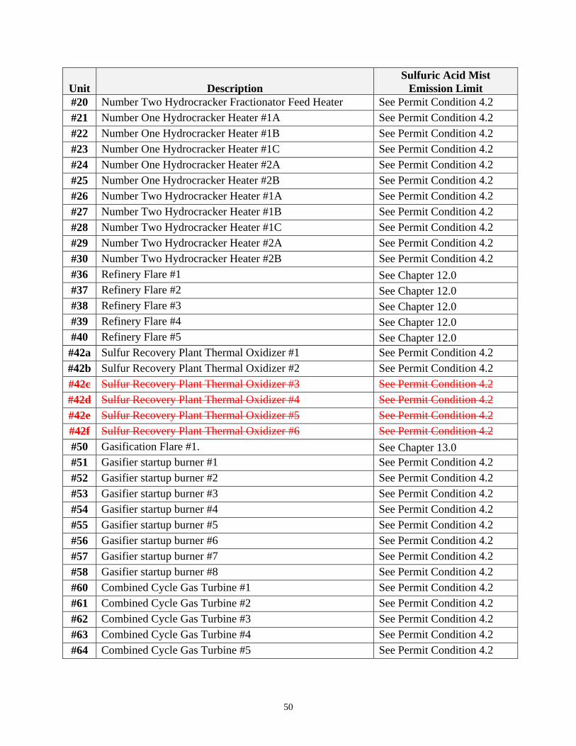
Unit
Sulfuric Acid Mist Description Emission Limit
#20 Number Two Hydrocracker Fractionator Feed Heater See Permit Condition 4.2 #21 Number One Hydrocracker Heater #1A See Permit Condition 4.2 #22 Number One Hydrocracker Heater #1B See Permit Condition 4.2 #23 Number One Hydrocracker Heater #1C See Permit Condition 4.2 #24 Number One Hydrocracker Heater #2A See Permit Condition 4.2 #25 Number One Hydrocracker Heater #2B See Permit Condition 4.2 #26 Number Two Hydrocracker Heater #1A See Permit Condition 4.2 #27 Number Two Hydrocracker Heater #1B See Permit Condition 4.2 #28 Number Two Hydrocracker Heater #1C See Permit Condition 4.2 #29 Number Two Hydrocracker Heater #2A See Permit Condition 4.2 #30 Number Two Hydrocracker Heater #2B See Permit Condition 4.2 #36 Refinery Flare #1 See Chapter 12.0 #37 Refinery Flare #2 See Chapter 12.0 #38 Refinery Flare #3 See Chapter 12.0 #39 Refinery Flare #4 See Chapter 12.0 #40 Refinery Flare #5 See Chapter 12.0 #42a Sulfur Recovery Plant Thermal Oxidizer #1 See Permit Condition 4.2 #42b Sulfur Recovery Plant Thermal Oxidizer #2 See Permit Condition 4.2 #42c Sulfur Recovery Plant Thermal Oxidizer #3 See Permit Condition 4.2 #42d Sulfur Recovery Plant Thermal Oxidizer #4 See Permit Condition 4.2 #42e Sulfur Recovery Plant Thermal Oxidizer #5 See Permit Condition 4.2 #42f Sulfur Recovery Plant Thermal Oxidizer #6 See Permit Condition 4.2 #50 Gasification Flare #1. See Chapter 13.0 #51 Gasifier startup burner #1 See Permit Condition 4.2 #52 Gasifier startup burner #2 See Permit Condition 4.2 #53 Gasifier startup burner #3 See Permit Condition 4.2 #54 Gasifier startup burner #4 See Permit Condition 4.2 #55 Gasifier startup burner #5 See Permit Condition 4.2 #56 Gasifier startup burner #6 See Permit Condition 4.2 #57 Gasifier startup burner #7 See Permit Condition 4.2 #58 Gasifier startup burner #8 See Permit Condition 4.2 #60 Combined Cycle Gas Turbine #1 See Permit Condition 4.2 #61 Combined Cycle Gas Turbine #2 See Permit Condition 4.2 #62 Combined Cycle Gas Turbine #3 See Permit Condition 4.2 #63 Combined Cycle Gas Turbine #4 See Permit Condition 4.2 #64 Combined Cycle Gas Turbine #5 See Permit Condition 4.2
50
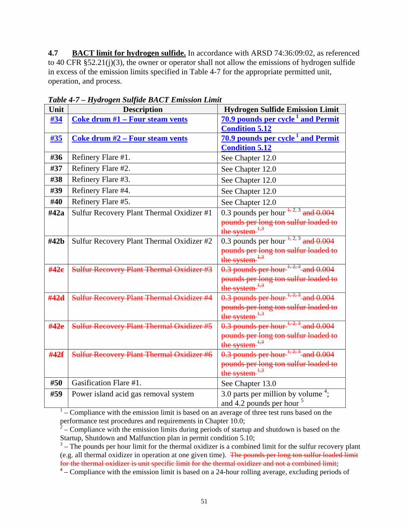
4.7 BACT limit for hydrogen sulfide. In accordance with ARSD 74:36:09:02, as referenced to 40 CFR §52.21(j)(3), the owner or operator shall not allow the emissions of hydrogen sulfide in excess of the emission limits specified in Table 4-7 for the appropriate permitted unit, operation, and process. Table 4-7 – Hydrogen Sulfide BACT Emission Limit Unit Description Hydrogen Sulfide Emission Limit #34 Coke drum #1 – Four steam vents 70.9 pounds per cycle 1 and Permit
Condition 5.12#35 Coke drum #2 – Four steam vents 70.9 pounds per cycle 1 and Permit
Condition 5.12#36 Refinery Flare #1. See Chapter 12.0 #37 Refinery Flare #2. See Chapter 12.0 #38 Refinery Flare #3. See Chapter 12.0 #39 Refinery Flare #4. See Chapter 12.0 #40 Refinery Flare #5. See Chapter 12.0 #42a Sulfur Recovery Plant Thermal Oxidizer #1 0.3 pounds per hour 1, 2, 3 and 0.004
pounds per long ton sulfur loaded to the system 1,3
#42b Sulfur Recovery Plant Thermal Oxidizer #2 0.3 pounds per hour 1, 2, 3 and 0.004 pounds per long ton sulfur loaded to the system 1,3
#42c Sulfur Recovery Plant Thermal Oxidizer #3 0.3 pounds per hour 1, 2, 3 and 0.004 pounds per long ton sulfur loaded to the system 1,3
#42d Sulfur Recovery Plant Thermal Oxidizer #4 0.3 pounds per hour 1, 2, 3 and 0.004 pounds per long ton sulfur loaded to the system 1,3
#42e Sulfur Recovery Plant Thermal Oxidizer #5 0.3 pounds per hour 1, 2, 3 and 0.004 pounds per long ton sulfur loaded to the system 1,3
#42f Sulfur Recovery Plant Thermal Oxidizer #6 0.3 pounds per hour 1, 2, 3 and 0.004 pounds per long ton sulfur loaded to the system 1,3
#50 Gasification Flare #1. See Chapter 13.0 #59 Power island acid gas removal system 3.0 parts per million by volume 4;
and 4.2 pounds per hour 5 1 – Compliance with the emission limit is based on an average of three test runs based on the performance test procedures and requirements in Chapter 10.0; 2 – Compliance with the emission limits during periods of startup and shutdown is based on the Startup, Shutdown and Malfunction plan in permit condition 5.10;
3 – The pounds per hour limit for the thermal oxidizer is a combined limit for the sulfur recovery plant (e.g. all thermal oxidizer in operation at one given time). The pounds per long ton sulfur loaded limit for the thermal oxidizer is unit specific limit for the thermal oxidizer and not a combined limit; 4 – Compliance with the emission limit is based on a 24-hour rolling average, excluding periods of
51
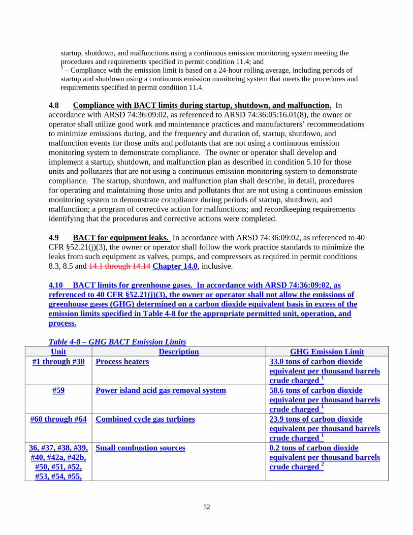
startup, shutdown, and malfunctions using a continuous emission monitoring system meeting the procedures and requirements specified in permit condition 11.4; and 5 – Compliance with the emission limit is based on a 24-hour rolling average, including periods of startup and shutdown using a continuous emission monitoring system that meets the procedures and requirements specified in permit condition 11.4.
4.8 Compliance with BACT limits during startup, shutdown, and malfunction. In accordance with ARSD 74:36:09:02, as referenced to ARSD 74:36:05:16.01(8), the owner or operator shall utilize good work and maintenance practices and manufacturers’ recommendations to minimize emissions during, and the frequency and duration of, startup, shutdown, and malfunction events for those units and pollutants that are not using a continuous emission monitoring system to demonstrate compliance. The owner or operator shall develop and implement a startup, shutdown, and malfunction plan as described in condition 5.10 for those units and pollutants that are not using a continuous emission monitoring system to demonstrate compliance. The startup, shutdown, and malfunction plan shall describe, in detail, procedures for operating and maintaining those units and pollutants that are not using a continuous emission monitoring system to demonstrate compliance during periods of startup, shutdown, and malfunction; a program of corrective action for malfunctions; and recordkeeping requirements identifying that the procedures and corrective actions were completed. 4.9 BACT for equipment leaks. In accordance with ARSD 74:36:09:02, as referenced to 40 CFR §52.21(j)(3), the owner or operator shall follow the work practice standards to minimize the leaks from such equipment as valves, pumps, and compressors as required in permit conditions 8.3, 8.5 and 14.1 through 14.14 Chapter 14.0, inclusive. 4.10 BACT limits for greenhouse gases. In accordance with ARSD 74:36:09:02, as referenced to 40 CFR §52.21(j)(3), the owner or operator shall not allow the emissions of greenhouse gases (GHG) determined on a carbon dioxide equivalent basis in excess of the emission limits specified in Table 4-8 for the appropriate permitted unit, operation, and process. Table 4-8 – GHG BACT Emission Limits Unit Description GHG Emission Limit
#1 through #30 Process heaters 33.0 tons of carbon dioxide equivalent per thousand barrels crude charged 1
#59 Power island acid gas removal system 58.6 tons of carbon dioxide equivalent per thousand barrels crude charged 1
#60 through #64 Combined cycle gas turbines 23.9 tons of carbon dioxide equivalent per thousand barrels crude charged 1
36, #37, #38, #39, #40, #42a, #42b,
#50, #51, #52, #53, #54, #55,
Small combustion sources 0.2 tons of carbon dioxide equivalent per thousand barrels crude charged 2
52
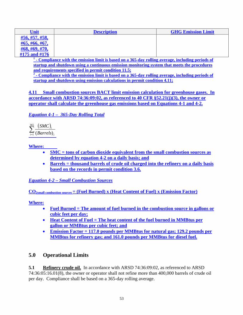
Unit Description GHG Emission Limit#56, #57, #58, #65, #66, #67, #68, #69, #70, #175 and #176
1 - Compliance with the emission limit is based on a 365-day rolling average, including periods of startup and shutdown using a continuous emission monitoring system that meets the procedures and requirements specified in permit condition 11.5; 2 - Compliance with the emission limit is based on a 365-day rolling average, including periods of startup and shutdown using emission calculations in permit condition 4.11;
4.11 Small combustion sources BACT limit emission calculation for greenhouse gases. In accordance with ARSD 74:36:09:02, as referenced to 40 CFR §52.21(j)(3), the owner or operator shall calculate the greenhouse gas emissions based on Equations 4-1 and 4-2. Equation 4-1 – 365-Day Rolling Total
( )∑=
365
1 )(i i
i
BarrelsSMC
Where:
• SMC = tons of carbon dioxide equivalent from the small combustion sources as determined by equation 4-2 on a daily basis; and
• Barrels = thousand barrels of crude oil charged into the refinery on a daily basis based on the records in permit condition 3.6.
Equation 4-2 – Small Combustion Sources CO2small combustion sources = (Fuel Burned) x (Heat Content of Fuel) x (Emission Factor) Where:
• Fuel Burned = The amount of fuel burned in the combustion source in gallons or cubic feet per day;
• Heat Content of Fuel = The heat content of the fuel burned in MMBtus per gallon or MMBtus per cubic feet; and
• Emission Factor = 117.0 pounds per MMBtus for natural gas; 129.2 pounds per MMBtus for refinery gas; and 161.0 pounds per MMBtus for diesel fuel.
5.0 Operational Limits 5.1 Refinery crude oil. In accordance with ARSD 74:36:09:02, as referenced to ARSD 74:36:05:16.01(8), the owner or operator shall not refine more than 400,000 barrels of crude oil per day. Compliance shall be based on a 365-day rolling average.
53
5.2 IGCC system. In accordance with ARSD 74:36:09:02, as referenced to ARSD 74:36:05:16.01(8), the owner or operator shall produce the hydrogen, electricity, and/or steam from the IGCC system for on-site use. The owner or operator shall not sell the hydrogen, electricity, and/or steam outside the Hyperion Energy Center major stationary source. 5.3 Cooling tower. In accordance with ARSD 74:36:09:02, as referenced to ARSD 74:36:05:16.01(8), the owner or operator shall install, operate, and maintain a 0.0005 percent efficient drift eliminators on Unit #41. Compliance for this operational limit is based on the manufacturer’s design specifications for the cooling tower. 5.4 Paved roads and parking lots. In accordance with ARSD 74:36:09:02, as referenced to ARSD 74:36:05:16.01(8), the owner or operator shall pave all haul roads and parking lots within the Hyperion Energy Center’s property boundaries at this location. The roads shall be paved prior to initial startup of the petroleum refinery. 5.5 Sulfur recovery plant. In accordance with ARSD 74:36:09:02, as referenced to ARSD 74:36:05:16.01(8), the owner or operator shall not input more than 2,040 long tons of sulfur per day into the six sulfur recovery plant trains and associated thermal oxidizers (Unit #42a through #42f and #42b). The owner or operator shall not operate the two thermal oxidizers associated with the sulfur recovery plant more than a combined 240 hours per 12-month rolling period. 5.6 Combined cycle combustion turbines. In accordance with ARSD 74:36:09:02, as referenced to ARSD 74:36:05:16.01(8), the owner or operator shall not operate more than four of the five combined cycle combustion turbine system (Unit #60 through #64) at any given time. The owner or operator is allowed to overlap the operations of the combined cycle combustion turbines during startup and shutdown of the units. The owner or operator shall not operate the five combined cycle combustion turbine system (Unit #60 through #64) with a combined heat input from ultra low sulfur distillate oil greater than 1,942,000 million Btus per 365-day rolling period. 5.7 Gasifier startup burner. In accordance with ARSD 74:36:09:02, as referenced to ARSD 74:36:05:16.01(8), the owner or operator shall not operate more than six of the eight gasifier startup burners (Unit #51 through #58) at any given time. The owner or operator is allowed to overlap the operations of the gasifier startup burners during startup and shutdown of the units. 5.8 Diesel generators and fire pumps. In accordance with ARSD 74:36:09:02, as referenced to ARSD 74:36:05:16.01(8), the owner or operator shall operate a 2008 model or newer generator and fire pump. The owner or operate shall not operate a 2007 model or older generator and/or fire pump. The owner or operator shall limit the operations of each generator and fire pump to less than 300 hours per 12-month rolling period. Operations during an emergency do not count against the 300 hour per 12-month rolling period limit. The owner or operator shall not operate more than one of the six diesel generators and fire pumps (Unit #65 through #70) at any give time.
54
5.9 Operation, maintenance, and monitoring plan. In accordance with ARSD 74:36:09:02, as referenced to ARSD 74:36:05:16.01(8), the owner or operator shall develop, maintain, and implement a written Operation, Maintenance, and Monitoring plan. The Operation, Maintenance, and Monitoring plan shall be submitted to the Secretary within 60 days prior to initial startup of the petroleum refinery. Any subsequent changes to the plan must be submitted to the Secretary for review and approval. Pending approval by the Secretary of an initial or amended plan, the owner or operator must comply with the provisions of the submitted plan. Each plan must contain the following information: 1. Process and control device parameters to be monitored to determine compliance, along with
established operating limits or ranges, as applicable, for each emission unit; 2. A monitoring schedule for each emission unit; 3. Procedures for the proper operation and maintenance of each emission unit and each air
pollution control device used to meet the applicable emission limits and operating limits in this permit;
4. Procedures for the proper installation, operation, and maintenance of monitoring devices or systems used to determine compliance include: a. Calibration and certification of accuracy of each monitoring device; b. Performance and equipment specifications for the sample interface, parametric signal
analyzer, and the data collection and reduction systems; and c. Ongoing operation and maintenance procedures in accordance with the following
requirements: i. Maintain and operate each continuous monitoring system in a manner consistent
with good air pollution control practices; ii. Maintain and operate each continuous monitoring system as specified in this
permit; iii. Maintain the necessary parts for routine repairs of each continuous monitoring
system; iv. Install, operate, and the data verified prior to or in conjunction with conducting
performance tests. The verification shall, at a minimum, include completion of the manufacturer’s written specifications or recommendations for installation, operation, and calibration of the system; and
v. Except for system breakdowns, out-of-control periods, repairs, maintenance periods, calibration checks, and zero (low-level) and high-level calibration drift adjustments, all continuous monitoring systems shall be in continuous operation.
5. Procedures for monitoring process and control device parameters. 6. Corrective actions to be taken when process or operating parameters or add-on control device
parameters deviate from the operating limits specified in this permit, including: a. Procedures to determine and record the cause of a deviation or excursion, and the time
the deviation or excursion began and ended; and b. Procedures for recording the corrective action taken, the time corrective action was
initiated, and the time and date the corrective action was completed; and 7. A maintenance schedule for each emission unit and control device that is consistent with the
manufacturer's instructions and recommendations for routine and long-term maintenance. 5.10 Startup, shutdown, and malfunction plan. In accordance with ARSD 74:36:09:02, as
55
referenced to ARSD 74:36:05:16.01(8), the owner or operator shall develop a written Startup, Shutdown, and Malfunction plan. The Startup, Shutdown, and Malfunction plan shall be submitted and approved by the Secretary within 90 days prior to initial startup of the petroleum refinery. Any subsequent changes to the plan must be submitted to the Secretary for review and approval. Pending approval by the Secretary of an initial or amended plan, the owner or operator must comply with the provisions of the submitted plan. The Startup, Shutdown, and Malfunction plan does not need to address any scenario that would not cause an exceedance of an applicable emission limit. The Startup, Shutdown, and Malfunction plan shall: 1. Describe in detail the procedures for operating and maintaining the units identified in Table
1-1 during periods of startup, shutdown, and malfunctions; 2. Identify a program of corrective action for a malfunction of the process, air pollutant control,
and monitoring equipment used to comply with the relevant standard; 3. Define the parameters that determine the operating period classified as a startup and
shutdown; 4. Ensure that at all times the owner or operator operates and maintains the units identified in
Table 1-1, and the associated air pollution control and monitoring equipment, in a manner which satisfies the general duty to minimize emissions;
5. Ensure that the owner or operator is prepared to correct malfunctions as soon as practicable after their occurrence in order to minimize excess emissions; and
6. Reduce the reporting burden associated with periods of startup, shutdown, and malfunction (including corrective action taken to restore malfunctioning process and air pollution control equipment to its normal or usual manner of operation).
To satisfy this requirement, the owner or operator may use its standard operating procedures manual, an Occupational Safety and Health Administration (OSHA) plan, or another plan, provided the alternative plans meet all the requirements of this permit condition. The owner or operator shall make revisions to the Startup, Shutdown, and Malfunction plan, if it is determined that the plan does not address a startup, shutdown, or malfunction event that has occurred; fails to provide for the operation of a unit (including associated air pollution control and monitoring equipment) during a startup, shutdown, or malfunction event in a manner consistent with the general duty to minimize emissions; or does not provide adequate procedures for correcting malfunctioning process and/or air pollution control and monitoring equipment as quickly as practicable. Revisions to the Startup, Shutdown, and Malfunction plan are not considered a permit revision. 5.11 Tank farm operation restriction. In accordance with ARSD 74:36:09:02, as referenced to ARSD 74:36:05:16.01(8), the owner or operator shall operate the storage tanks in the tank farm under one of the two operating scenarios: 1. The volatile organic compound emissions from Units # 71 through #174 and Unit #177 shall
be routed to one of the two thermal oxidizers identified as Unit #175 and/or #176; or 2. The volatile organic compound emissions from Units #71 through #96, Units #111 through
#133, Unit #140, Unit #146, Units #149 through #162, and Units #166 through #171, and Unit #177 shall be routed to one of the two thermal oxidizers identified as Unit #175 and/or #176. The liquid stored in Units #97 through 110, Units #134 through #139, Units #141
56
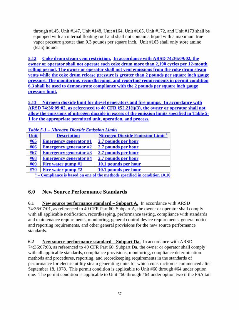
through #145, Unit #147, Unit #148, Unit #164, Unit #165, Unit #172, and Unit #173 shall be equipped with an internal floating roof and shall not contain a liquid with a maximum true vapor pressure greater than 0.3 pounds per square inch. Unit #163 shall only store amine (lean) liquid.
5.12 Coke drum steam vent restriction. In accordance with ARSD 74:36:09:02, the owner or operator shall not operate each coke drum more than 2,190 cycles per 12-month rolling period. The owner or operator shall not vent emissions from the coke drum steam vents while the coke drum release pressure is greater than 2 pounds per square inch gauge pressure. The monitoring, recordkeeping, and reporting requirements in permit condition 6.3 shall be used to demonstrate compliance with the 2 pounds per square inch gauge pressure limit. 5.13 Nitrogen dioxide limit for diesel generators and fire pumps. In accordance with ARSD 74:36:09:02, as referenced to 40 CFR §52.21(j)(3), the owner or operator shall not allow the emissions of nitrogen dioxide in excess of the emission limits specified in Table 5-1 for the appropriate permitted unit, operation, and process. Table 5-1 – Nitrogen Dioxide Emission Limits Unit Description Nitrogen Dioxide Emission Limit 1
#65 Emergency generator #1 2.7 pounds per hour#66 Emergency generator #2 2.7 pounds per hour#67 Emergency generator #3 2.7 pounds per hour#68 Emergency generator #4 2.7 pounds per hour#69 Fire water pump #1 10.1 pounds per hour#70 Fire water pump #2 10.1 pounds per hour
1 – Compliance is based on one of the methods specified in condition 10.16 6.0 New Source Performance Standards 6.1 New source performance standard – Subpart A. In accordance with ARSD 74:36:07:01, as referenced to 40 CFR Part 60, Subpart A, the owner or operator shall comply with all applicable notification, recordkeeping, performance testing, compliance with standards and maintenance requirements, monitoring, general control device requirements, general notice and reporting requirements, and other general provisions for the new source performance standards. 6.2 New source performance standard – Subpart Da. In accordance with ARSD 74:36:07:03, as referenced to 40 CFR Part 60, Subpart Da, the owner or operator shall comply with all applicable standards, compliance provisions, monitoring, compliance determination methods and procedures, reporting, and recordkeeping requirements in the standards of performance for electric utility steam generating units for which construction is commenced after September 18, 1978. This permit condition is applicable to Unit #60 through #64 under option one. The permit condition is applicable to Unit #60 through #64 under option two if the PSA tail
57

gas provides 50 percent or more of the fuel source to Unit #60 through #64. 6.3 New source performance standard – Subpart Ja. In accordance with 40 CFR Part 60, Subpart Ja, the owner or operator shall comply with all applicable emission limitations, work practice standards, performance tests, monitoring of emissions and operations, reporting, and recordkeeping requirements in the standards of performance for petroleum refineries that commenced construction, reconstruction, or modification after May 14, 2007. This permit condition is applicable to Unit #1 through #40, #42a through #42f, #42b, #45a, and #50 through #64. 6.4 New source performance standard – Subpart Kb. In accordance with ARSD 74:36:07:14, as referenced to 40 CFR Part 60, Subpart Kb, the owner or operator shall comply with all applicable standards, testing, alternative emission limits, reporting, recordkeeping, monitoring requirements in the standards of performance for volatile organic liquid storage vessels (including petroleum liquid storage vessels) for which construction, reconstruction or modification commences after July 23, 1984. This permit condition is applicable to Unit #160, #161, and #162. 6.5 New source performance standard – Subpart Y. In accordance with ARSD 74:36:07:16, as referenced to 40 CFR Part 60, Subpart Y, the owner or operator shall comply with all applicable standards, monitoring, and testing requirements in the standards of performance for coal preparation plants. This permit condition is applicable to Unit #47. 6.6 New source performance standard – Subpart UU. In accordance with ARSD 74:36:07:71, as referenced to 40 CFR Part 60, Subpart UU, the owner or operator shall comply with all applicable standards, monitoring, and testing requirements in the standards of performance for asphalt processing and asphalt roofing manufacture. This permit condition is applicable to Unit #154 and #155. 6.7 New source performance standard – Subpart NNN. In accordance with ARSD 74:36:07:26, as referenced to 40 CFR Part 60, Subpart NNN, the owner or operator shall comply with all applicable standards, monitoring, testing, reporting, and recordkeeping requirements in the standards of performance for volatile organic compound emissions from synthetic organic chemical manufacturing industry (SOCMI) distillation operations. This permit condition is applicable to processes that produce refinery gas or burn refinery gas. 6.8 New source performance standard – Subpart OOO. In accordance with ARSD 74:36:07:27, as referenced to 40 CFR Part 60, Subpart OOO, the owner or operator shall comply with all applicable standards and limitations, reporting, monitoring, recordkeeping, testing, and notification requirements in the standards of performance for nonmetallic mineral processing plants. This permit condition is applicable to Unit #48 the fugitive emissions from the flux building. 6.9 New source performance standard – Subpart RRR. In accordance with ARSD 74:36:07:32, as referenced to 40 CFR Part 60, Subpart RRR, the owner or operator shall comply with all applicable standards, monitoring, testing, reporting, and recordkeeping requirements in
58
the standards of performance for volatile organic compound emissions from synthetic organic chemical manufacturing industry (SOCMI) reactor processes. This permit condition is applicable to processes that produce refinery gas or burn refinery gas. 6.10 New source performance standard – Subpart IIII. In accordance with ARSD 74:36:07:88, as referenced to 40 CFR Part 60, Subpart IIII, the owner or operator shall comply with all applicable standards, fuel requirements, monitoring, compliance, testing, notification, reporting, and recordkeeping requirements in the standards of performance for stationary compression ignition internal combustion engines. This permit condition is applicable to Unit #65 through #70. 6.11 New source performance standard – Subpart KKKK. In accordance with ARSD 74:36:07:89, as referenced to 40 CFR Part 60, Subpart KKKK, the owner or operator shall comply with all applicable limits, compliance, monitoring, reporting, and testing requirements in the standards of performance for stationary combustion turbines. This permit condition is applicable to Unit #60 through #64. The permit condition is applicable to Unit #60 through #64 under option two if the PSA tail gas provides less than 50 percent of the fuel source to Unit #60 through #64. 7.0 National Emission Standards for Hazardous Air Pollutants 7.1 National emission standards for hazardous air pollutants – Subpart A. In accordance with ARSD 74:36:08:01, as referenced to 40 CFR Part 61, Subpart A, the owner or operator shall comply with all applicable notification, reporting, compliance, testing, and monitoring requirements, and other general provisions for the national emission standards for hazardous air pollutants. 7.2 National emission standards for hazardous air pollutants – Subpart FF. In accordance with 40 CFR Part 61, Subpart FF, the owner or operator shall comply with all applicable standards, alternative limits, monitoring, testing, reporting, and recordkeeping requirements in the national emission standards for benzene waste operations. 8.0 Maximum Achievable Control Technology Standard 8.1 Maximum Achievable Control Technology Standard – Subpart A. In accordance with ARSD 74:36:08:03, as referenced to 40 CFR Part 63 Subpart A, the owner or operator shall comply with all applicable notification, compliance, maintenance, testing, monitoring, reporting, recordkeeping, and control device requirements, and other general provisions for maximum achievable control technology standards. 8.2 Maximum Achievable Control Technology Standard – Subpart B. In accordance with ARSD 74:36:08:03.01, as referenced to 40 CFR Part 63, Subpart B, the owner or operator shall comply with all applicable standards and limits in Table 8-1.
59
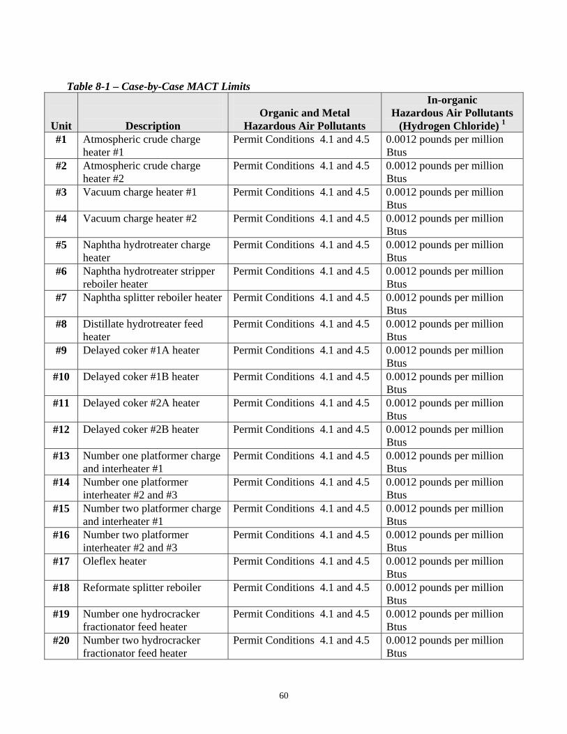
Table 8-1 – Case-by-Case MACT Limits
Unit
Description
Organic and Metal
Hazardous Air Pollutants
In-organic Hazardous Air Pollutants
(Hydrogen Chloride) 1 #1 Atmospheric crude charge
heater #1 Permit Conditions 4.1 and 4.5 0.0012 pounds per million
Btus #2 Atmospheric crude charge
heater #2 Permit Conditions 4.1 and 4.5 0.0012 pounds per million
Btus #3 Vacuum charge heater #1 Permit Conditions 4.1 and 4.5 0.0012 pounds per million
Btus #4 Vacuum charge heater #2 Permit Conditions 4.1 and 4.5 0.0012 pounds per million
Btus #5 Naphtha hydrotreater charge
heater Permit Conditions 4.1 and 4.5 0.0012 pounds per million
Btus #6 Naphtha hydrotreater stripper
reboiler heater Permit Conditions 4.1 and 4.5 0.0012 pounds per million
Btus #7 Naphtha splitter reboiler heater Permit Conditions 4.1 and 4.5 0.0012 pounds per million
Btus #8 Distillate hydrotreater feed
heater Permit Conditions 4.1 and 4.5 0.0012 pounds per million
Btus #9 Delayed coker #1A heater Permit Conditions 4.1 and 4.5 0.0012 pounds per million
Btus #10 Delayed coker #1B heater Permit Conditions 4.1 and 4.5 0.0012 pounds per million
Btus #11 Delayed coker #2A heater Permit Conditions 4.1 and 4.5 0.0012 pounds per million
Btus #12 Delayed coker #2B heater Permit Conditions 4.1 and 4.5 0.0012 pounds per million
Btus #13 Number one platformer charge
and interheater #1 Permit Conditions 4.1 and 4.5 0.0012 pounds per million
Btus #14 Number one platformer
interheater #2 and #3 Permit Conditions 4.1 and 4.5 0.0012 pounds per million
Btus #15 Number two platformer charge
and interheater #1 Permit Conditions 4.1 and 4.5 0.0012 pounds per million
Btus #16 Number two platformer
interheater #2 and #3 Permit Conditions 4.1 and 4.5 0.0012 pounds per million
Btus #17 Oleflex heater Permit Conditions 4.1 and 4.5 0.0012 pounds per million
Btus #18 Reformate splitter reboiler Permit Conditions 4.1 and 4.5 0.0012 pounds per million
Btus #19 Number one hydrocracker
fractionator feed heater Permit Conditions 4.1 and 4.5 0.0012 pounds per million
Btus #20 Number two hydrocracker
fractionator feed heater Permit Conditions 4.1 and 4.5 0.0012 pounds per million
Btus
60
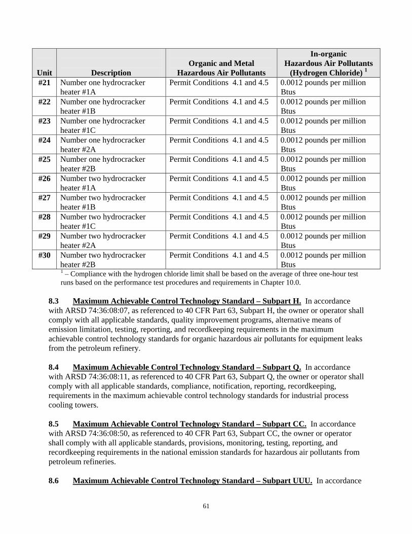
Unit
Description
In-organic Organic and Metal Hazardous Air Pollutants
Hazardous Air Pollutants (Hydrogen Chloride) 1 #21 Number one hydrocracker
heater #1A Permit Conditions 4.1 and 4.5 0.0012 pounds per million
Btus #22 Number one hydrocracker
heater #1B Permit Conditions 4.1 and 4.5 0.0012 pounds per million
Btus #23 Number one hydrocracker
heater #1C Permit Conditions 4.1 and 4.5 0.0012 pounds per million
Btus #24 Number one hydrocracker
heater #2A Permit Conditions 4.1 and 4.5 0.0012 pounds per million
Btus #25 Number one hydrocracker
heater #2B Permit Conditions 4.1 and 4.5 0.0012 pounds per million
Btus #26 Number two hydrocracker
heater #1A Permit Conditions 4.1 and 4.5 0.0012 pounds per million
Btus #27 Number two hydrocracker
heater #1B Permit Conditions 4.1 and 4.5 0.0012 pounds per million
Btus #28 Number two hydrocracker
heater #1C Permit Conditions 4.1 and 4.5 0.0012 pounds per million
Btus #29 Number two hydrocracker
heater #2A Permit Conditions 4.1 and 4.5 0.0012 pounds per million
Btus #30 Number two hydrocracker
heater #2B Permit Conditions 4.1 and 4.5 0.0012 pounds per million
Btus 1 – Compliance with the hydrogen chloride limit shall be based on the average of three one-hour test runs based on the performance test procedures and requirements in Chapter 10.0.
8.3 Maximum Achievable Control Technology Standard – Subpart H. In accordance with ARSD 74:36:08:07, as referenced to 40 CFR Part 63, Subpart H, the owner or operator shall comply with all applicable standards, quality improvement programs, alternative means of emission limitation, testing, reporting, and recordkeeping requirements in the maximum achievable control technology standards for organic hazardous air pollutants for equipment leaks from the petroleum refinery. 8.4 Maximum Achievable Control Technology Standard – Subpart Q. In accordance with ARSD 74:36:08:11, as referenced to 40 CFR Part 63, Subpart Q, the owner or operator shall comply with all applicable standards, compliance, notification, reporting, recordkeeping, requirements in the maximum achievable control technology standards for industrial process cooling towers. 8.5 Maximum Achievable Control Technology Standard – Subpart CC. In accordance with ARSD 74:36:08:50, as referenced to 40 CFR Part 63, Subpart CC, the owner or operator shall comply with all applicable standards, provisions, monitoring, testing, reporting, and recordkeeping requirements in the national emission standards for hazardous air pollutants from petroleum refineries. 8.6 Maximum Achievable Control Technology Standard – Subpart UUU. In accordance
61
with ARSD 74:36:08:67, as referenced to 40 CFR Part 63, Subpart UUU, the owner or operator shall comply with all applicable limitations, work practice standards, testing, monitoring, reporting, and recordkeeping requirements in the national emission standards for hazardous air pollutants from petroleum refineries – catalytic cracking, catalytic reforming, and sulfur recovery units. 9.0 Other Applicable Limits 9.1 State opacity limit. In accordance with ARSD 74:36:12:01, the owner or operator may not discharge into the ambient air an air contaminant of a density equal to or greater than that designated as 20 percent opacity from any permitted unit, operation, or process listed in Table 1-1. This provision does not apply when the presence of uncombined water is the only reason for failure to meet the requirement. An exceedance of the opacity limit is not considered a violation during brief periods of soot blowing, startup, shutdown, or malfunction. Malfunction means any sudden and unavoidable failure of air pollution control equipment, process equipment, or a process to operate in a normal or usual manner. A failure caused entirely or in part by poor maintenance, careless operation, preventable equipment breakdown, or any other cause within the control of the owner or operator of the source is not a malfunction and is considered a violation. 10.0 PERFORMANCE TESTS 10.1 Performance test may be required. In accordance with ARSD 74:36:11:02, the Secretary may request a performance test. A performance test shall be conducted while operating the unit at or greater than 90 percent of its maximum design capacity, unless otherwise specified by the Secretary. A performance test that is conducted while operating the unit less than 90 percent of its maximum design capacity will result in the operation being limited to the percent achieved during the performance test. The Secretary has the discretion to extend the deadline for completion of the performance test required by the Secretary, if circumstances reasonably warrant but will not extend the deadline past a federally required performance test deadline. 10.2 Test methods and procedures. The owner or operator shall conduct the performance test in accordance with 40 CFR Part 60, Appendix A; 40 CFR Part 63, Appendix A; and 40 CFR Part 51, Appendix M. The Secretary may approve an alternative method if a performance test specified in 40 CFR Part 60, Appendix A; 40 CFR Part 63, Appendix A; and 40 CFR Part 51, Appendix M is not federally applicable or federally required. 10.3 Representative performance test. In accordance with ARSD 74:36:07:01, as referenced to 40 CFR §60.8(c), performance tests shall be conducted under such conditions as the Secretary shall specify to the owner or operator based on the representative performance of the unit being tested. The owner or operator shall make available to the Secretary such records as may be necessary to determine the conditions of the performance tests. Operations during
62
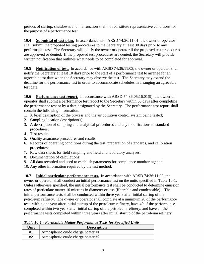
periods of startup, shutdown, and malfunction shall not constitute representative conditions for the purpose of a performance test. 10.4 Submittal of test plan. In accordance with ARSD 74:36:11:01, the owner or operator shall submit the proposed testing procedures to the Secretary at least 30 days prior to any performance test. The Secretary will notify the owner or operator if the proposed test procedures are approved or denied. If the proposed test procedures are denied, the Secretary will provide written notification that outlines what needs to be completed for approval. 10.5 Notification of test. In accordance with ARSD 74:36:11:03, the owner or operator shall notify the Secretary at least 10 days prior to the start of a performance test to arrange for an agreeable test date when the Secretary may observe the test. The Secretary may extend the deadline for the performance test in order to accommodate schedules in arranging an agreeable test date. 10.6 Performance test report. In accordance with ARSD 74:36:05:16.01(9), the owner or operator shall submit a performance test report to the Secretary within 60 days after completing the performance test or by a date designated by the Secretary. The performance test report shall contain the following information: 1. A brief description of the process and the air pollution control system being tested; 2. Sampling location description(s); 3. A description of sampling and analytical procedures and any modifications to standard
procedures; 4. Test results; 5. Quality assurance procedures and results; 6. Records of operating conditions during the test, preparation of standards, and calibration
procedures; 7. Raw data sheets for field sampling and field and laboratory analyses; 8. Documentation of calculations; 9. All data recorded and used to establish parameters for compliance monitoring; and 10. Any other information required by the test method. 10.7 Initial particulate performance tests. In accordance with ARSD 74:36:11:02, the owner or operator shall conduct an initial performance test on the units specified in Table 10-1. Unless otherwise specified, the initial performance test shall be conducted to determine emission rates of particulate matter 10 microns in diameter or less (filterable and condensable). The initial performance tests shall be conducted within three years after initial startup of the petroleum refinery. The owner or operator shall complete at a minimum 20 of the performance tests within one year after initial startup of the petroleum refinery, have 40 of the performance completed within two years after initial startup of the petroleum refinery, and have all the performance tests completed within three years after initial startup of the petroleum refinery. Table 10-1 - Particulate Matter Performance Tests for Specified Units
Unit Description #1 Atmospheric crude charge heater #1 #2 Atmospheric crude charge heater #2
63
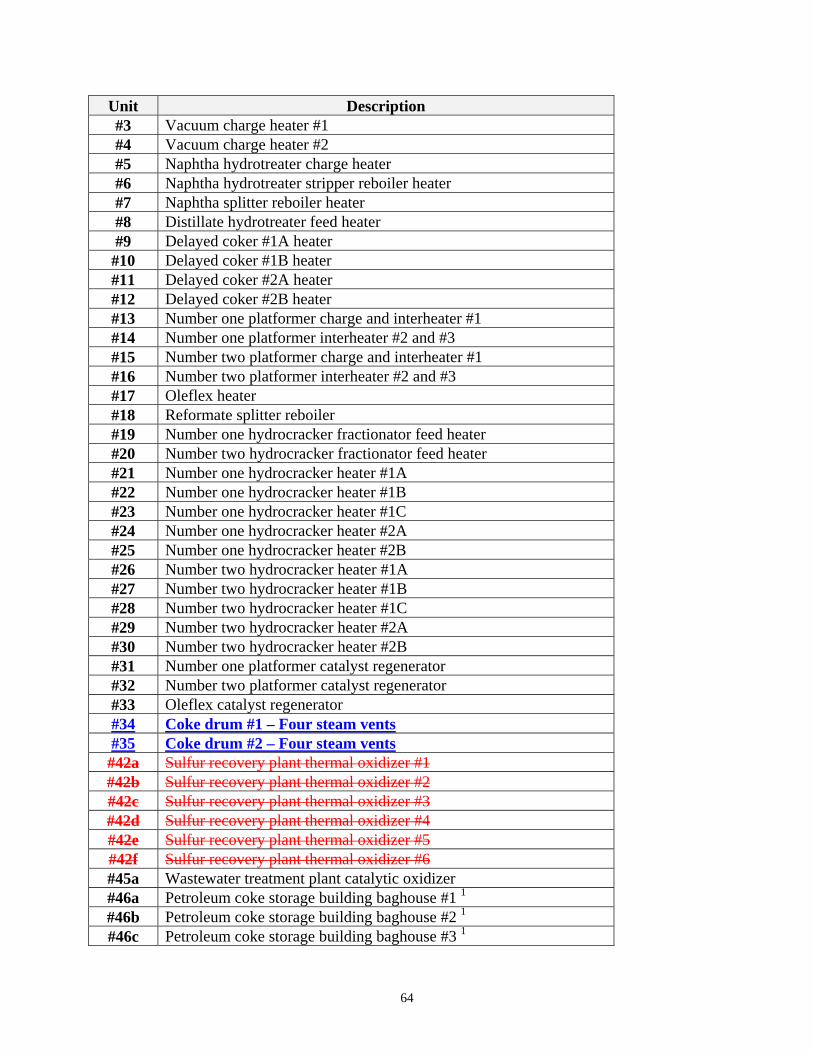
Unit Description #3 Vacuum charge heater #1 #4 Vacuum charge heater #2 #5 Naphtha hydrotreater charge heater #6 Naphtha hydrotreater stripper reboiler heater #7 Naphtha splitter reboiler heater #8 Distillate hydrotreater feed heater #9 Delayed coker #1A heater #10 Delayed coker #1B heater #11 Delayed coker #2A heater #12 Delayed coker #2B heater #13 Number one platformer charge and interheater #1 #14 Number one platformer interheater #2 and #3 #15 Number two platformer charge and interheater #1 #16 Number two platformer interheater #2 and #3 #17 Oleflex heater #18 Reformate splitter reboiler #19 Number one hydrocracker fractionator feed heater #20 Number two hydrocracker fractionator feed heater #21 Number one hydrocracker heater #1A #22 Number one hydrocracker heater #1B #23 Number one hydrocracker heater #1C #24 Number one hydrocracker heater #2A #25 Number one hydrocracker heater #2B #26 Number two hydrocracker heater #1A #27 Number two hydrocracker heater #1B #28 Number two hydrocracker heater #1C #29 Number two hydrocracker heater #2A #30 Number two hydrocracker heater #2B #31 Number one platformer catalyst regenerator #32 Number two platformer catalyst regenerator #33 Oleflex catalyst regenerator #34 Coke drum #1 – Four steam vents#35 Coke drum #2 – Four steam vents#42a Sulfur recovery plant thermal oxidizer #1 #42b Sulfur recovery plant thermal oxidizer #2 #42c Sulfur recovery plant thermal oxidizer #3 #42d Sulfur recovery plant thermal oxidizer #4 #42e Sulfur recovery plant thermal oxidizer #5 #42f Sulfur recovery plant thermal oxidizer #6 #45a Wastewater treatment plant catalytic oxidizer #46a Petroleum coke storage building baghouse #1 1 #46b Petroleum coke storage building baghouse #2 1 #46c Petroleum coke storage building baghouse #3 1
64
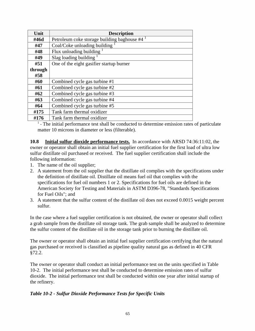
Unit Description #46d Petroleum coke storage building baghouse #4 1 #47 Coal/Coke unloading building 1 #48 Flux unloading building 1 #49 Slag loading building 1 #51
through #58
One of the eight gasifier startup burner
#60 Combined cycle gas turbine #1 #61 Combined cycle gas turbine #2 #62 Combined cycle gas turbine #3 #63 Combined cycle gas turbine #4 #64 Combined cycle gas turbine #5 #175 Tank farm thermal oxidizer #176 Tank farm thermal oxidizer
1 - The initial performance test shall be conducted to determine emission rates of particulate matter 10 microns in diameter or less (filterable).
10.8 Initial sulfur dioxide performance tests. In accordance with ARSD 74:36:11:02, the owner or operator shall obtain an initial fuel supplier certification for the first load of ultra low sulfur distillate oil purchased or received. The fuel supplier certification shall include the following information: 1. The name of the oil supplier; 2. A statement from the oil supplier that the distillate oil complies with the specifications under
the definition of distillate oil. Distillate oil means fuel oil that complies with the specifications for fuel oil numbers 1 or 2. Specifications for fuel oils are defined in the American Society for Testing and Materials in ASTM D396-78, "Standards Specifications for Fuel Oils"; and
3. A statement that the sulfur content of the distillate oil does not exceed 0.0015 weight percent sulfur.
In the case where a fuel supplier certification is not obtained, the owner or operator shall collect a grab sample from the distillate oil storage tank. The grab sample shall be analyzed to determine the sulfur content of the distillate oil in the storage tank prior to burning the distillate oil. The owner or operator shall obtain an initial fuel supplier certification certifying that the natural gas purchased or received is classified as pipeline quality natural gas as defined in 40 CFR §72.2. The owner or operator shall conduct an initial performance test on the units specified in Table 10-2. The initial performance test shall be conducted to determine emission rates of sulfur dioxide. The initial performance test shall be conducted within one year after initial startup of the refinery. Table 10-2 - Sulfur Dioxide Performance Tests for Specific Units
65
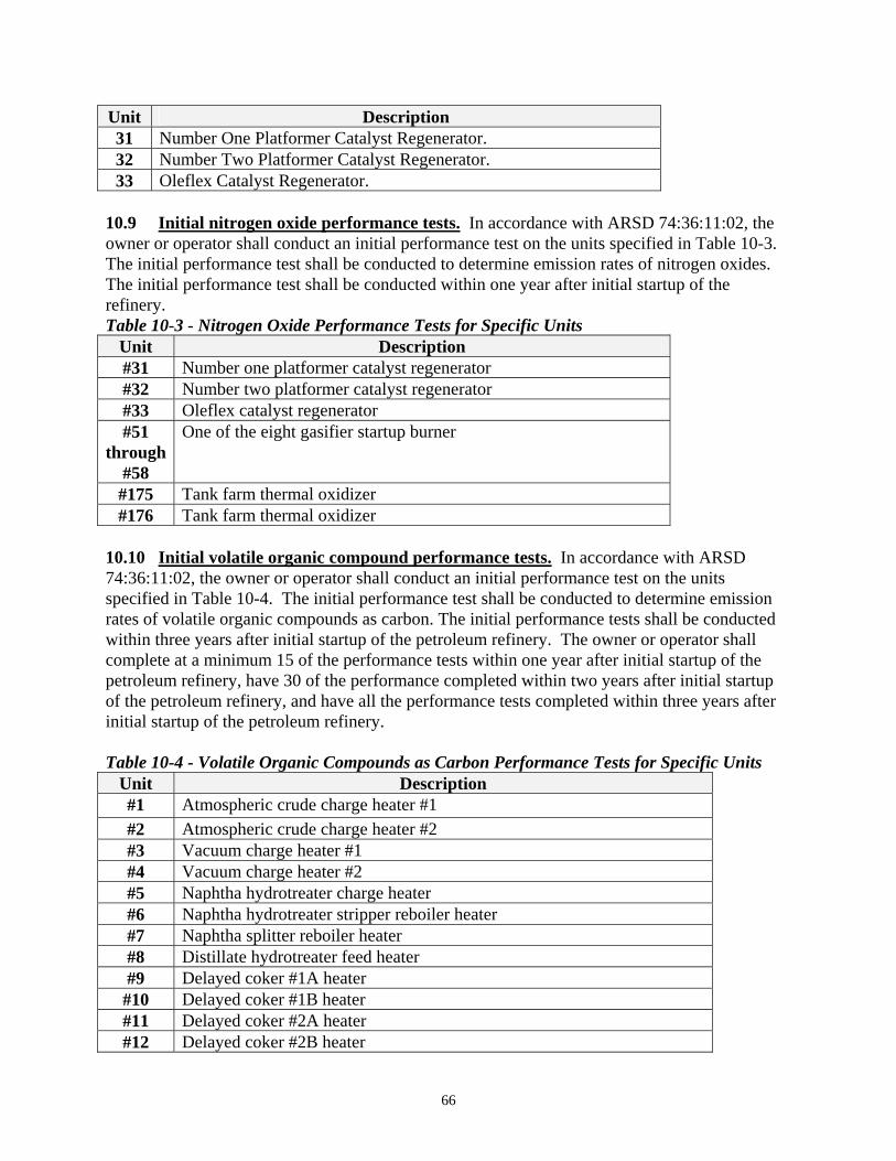
Unit Description 31 Number One Platformer Catalyst Regenerator. 32 Number Two Platformer Catalyst Regenerator. 33 Oleflex Catalyst Regenerator.
10.9 Initial nitrogen oxide performance tests. In accordance with ARSD 74:36:11:02, the owner or operator shall conduct an initial performance test on the units specified in Table 10-3. The initial performance test shall be conducted to determine emission rates of nitrogen oxides. The initial performance test shall be conducted within one year after initial startup of the refinery. Table 10-3 - Nitrogen Oxide Performance Tests for Specific Units
Unit Description #31 Number one platformer catalyst regenerator #32 Number two platformer catalyst regenerator #33 Oleflex catalyst regenerator #51
through #58
One of the eight gasifier startup burner
#175 Tank farm thermal oxidizer #176 Tank farm thermal oxidizer
10.10 Initial volatile organic compound performance tests. In accordance with ARSD 74:36:11:02, the owner or operator shall conduct an initial performance test on the units specified in Table 10-4. The initial performance test shall be conducted to determine emission rates of volatile organic compounds as carbon. The initial performance tests shall be conducted within three years after initial startup of the petroleum refinery. The owner or operator shall complete at a minimum 15 of the performance tests within one year after initial startup of the petroleum refinery, have 30 of the performance completed within two years after initial startup of the petroleum refinery, and have all the performance tests completed within three years after initial startup of the petroleum refinery. Table 10-4 - Volatile Organic Compounds as Carbon Performance Tests for Specific Units
Unit Description #1 Atmospheric crude charge heater #1 #2 Atmospheric crude charge heater #2 #3 Vacuum charge heater #1 #4 Vacuum charge heater #2 #5 Naphtha hydrotreater charge heater #6 Naphtha hydrotreater stripper reboiler heater #7 Naphtha splitter reboiler heater #8 Distillate hydrotreater feed heater #9 Delayed coker #1A heater #10 Delayed coker #1B heater #11 Delayed coker #2A heater #12 Delayed coker #2B heater
66
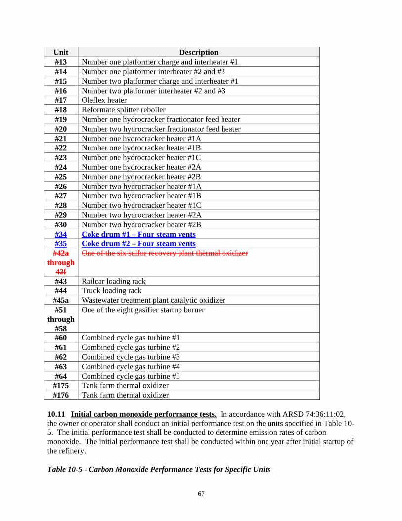
Unit Description #13 Number one platformer charge and interheater #1 #14 Number one platformer interheater #2 and #3 #15 Number two platformer charge and interheater #1 #16 Number two platformer interheater #2 and #3 #17 Oleflex heater #18 Reformate splitter reboiler #19 Number one hydrocracker fractionator feed heater #20 Number two hydrocracker fractionator feed heater #21 Number one hydrocracker heater #1A #22 Number one hydrocracker heater #1B #23 Number one hydrocracker heater #1C #24 Number one hydrocracker heater #2A #25 Number one hydrocracker heater #2B #26 Number two hydrocracker heater #1A #27 Number two hydrocracker heater #1B #28 Number two hydrocracker heater #1C #29 Number two hydrocracker heater #2A #30 Number two hydrocracker heater #2B #34 Coke drum #1 – Four steam vents#35 Coke drum #2 – Four steam vents#42a
through 42f
One of the six sulfur recovery plant thermal oxidizer
#43 Railcar loading rack #44 Truck loading rack #45a Wastewater treatment plant catalytic oxidizer #51
through #58
One of the eight gasifier startup burner
#60 Combined cycle gas turbine #1 #61 Combined cycle gas turbine #2 #62 Combined cycle gas turbine #3 #63 Combined cycle gas turbine #4 #64 Combined cycle gas turbine #5 #175 Tank farm thermal oxidizer #176 Tank farm thermal oxidizer
10.11 Initial carbon monoxide performance tests. In accordance with ARSD 74:36:11:02, the owner or operator shall conduct an initial performance test on the units specified in Table 10-5. The initial performance test shall be conducted to determine emission rates of carbon monoxide. The initial performance test shall be conducted within one year after initial startup of the refinery. Table 10-5 - Carbon Monoxide Performance Tests for Specific Units
67
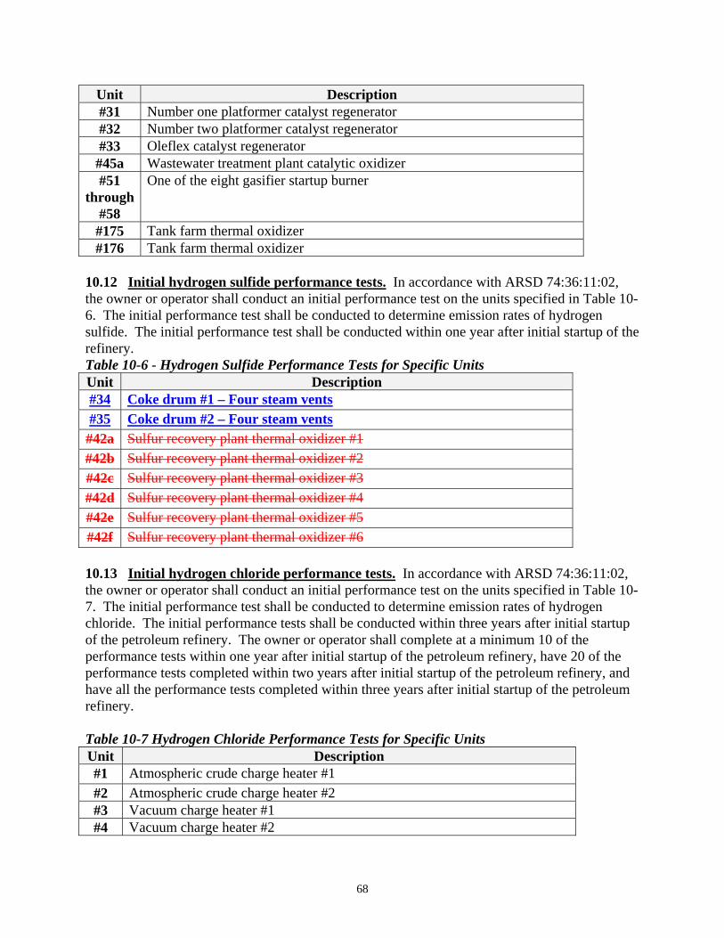
Unit Description #31 Number one platformer catalyst regenerator #32 Number two platformer catalyst regenerator #33 Oleflex catalyst regenerator #45a Wastewater treatment plant catalytic oxidizer #51
through #58
One of the eight gasifier startup burner
#175 Tank farm thermal oxidizer #176 Tank farm thermal oxidizer
10.12 Initial hydrogen sulfide performance tests. In accordance with ARSD 74:36:11:02, the owner or operator shall conduct an initial performance test on the units specified in Table 10-6. The initial performance test shall be conducted to determine emission rates of hydrogen sulfide. The initial performance test shall be conducted within one year after initial startup of the refinery. Table 10-6 - Hydrogen Sulfide Performance Tests for Specific Units Unit Description #34 Coke drum #1 – Four steam vents#35 Coke drum #2 – Four steam vents#42a Sulfur recovery plant thermal oxidizer #1 #42b Sulfur recovery plant thermal oxidizer #2 #42c Sulfur recovery plant thermal oxidizer #3 #42d Sulfur recovery plant thermal oxidizer #4 #42e Sulfur recovery plant thermal oxidizer #5 #42f Sulfur recovery plant thermal oxidizer #6 10.13 Initial hydrogen chloride performance tests. In accordance with ARSD 74:36:11:02, the owner or operator shall conduct an initial performance test on the units specified in Table 10-7. The initial performance test shall be conducted to determine emission rates of hydrogen chloride. The initial performance tests shall be conducted within three years after initial startup of the petroleum refinery. The owner or operator shall complete at a minimum 10 of the performance tests within one year after initial startup of the petroleum refinery, have 20 of the performance tests completed within two years after initial startup of the petroleum refinery, and have all the performance tests completed within three years after initial startup of the petroleum refinery. Table 10-7 Hydrogen Chloride Performance Tests for Specific Units Unit Description #1 Atmospheric crude charge heater #1 #2 Atmospheric crude charge heater #2 #3 Vacuum charge heater #1 #4 Vacuum charge heater #2
68
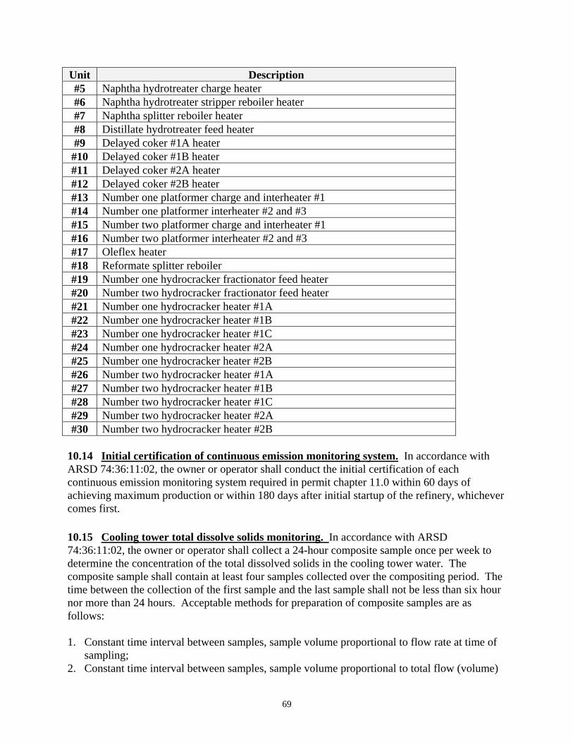
Unit Description #5 Naphtha hydrotreater charge heater #6 Naphtha hydrotreater stripper reboiler heater #7 Naphtha splitter reboiler heater #8 Distillate hydrotreater feed heater #9 Delayed coker #1A heater #10 Delayed coker #1B heater #11 Delayed coker #2A heater #12 Delayed coker #2B heater #13 Number one platformer charge and interheater #1 #14 Number one platformer interheater #2 and #3 #15 Number two platformer charge and interheater #1 #16 Number two platformer interheater #2 and #3 #17 Oleflex heater #18 Reformate splitter reboiler #19 Number one hydrocracker fractionator feed heater #20 Number two hydrocracker fractionator feed heater #21 Number one hydrocracker heater #1A #22 Number one hydrocracker heater #1B #23 Number one hydrocracker heater #1C #24 Number one hydrocracker heater #2A #25 Number one hydrocracker heater #2B #26 Number two hydrocracker heater #1A #27 Number two hydrocracker heater #1B #28 Number two hydrocracker heater #1C #29 Number two hydrocracker heater #2A #30 Number two hydrocracker heater #2B
10.14 Initial certification of continuous emission monitoring system. In accordance with ARSD 74:36:11:02, the owner or operator shall conduct the initial certification of each continuous emission monitoring system required in permit chapter 11.0 within 60 days of achieving maximum production or within 180 days after initial startup of the refinery, whichever comes first. 10.15 Cooling tower total dissolve solids monitoring. In accordance with ARSD 74:36:11:02, the owner or operator shall collect a 24-hour composite sample once per week to determine the concentration of the total dissolved solids in the cooling tower water. The composite sample shall contain at least four samples collected over the compositing period. The time between the collection of the first sample and the last sample shall not be less than six hour nor more than 24 hours. Acceptable methods for preparation of composite samples are as follows: 1. Constant time interval between samples, sample volume proportional to flow rate at time of
sampling; 2. Constant time interval between samples, sample volume proportional to total flow (volume)
69
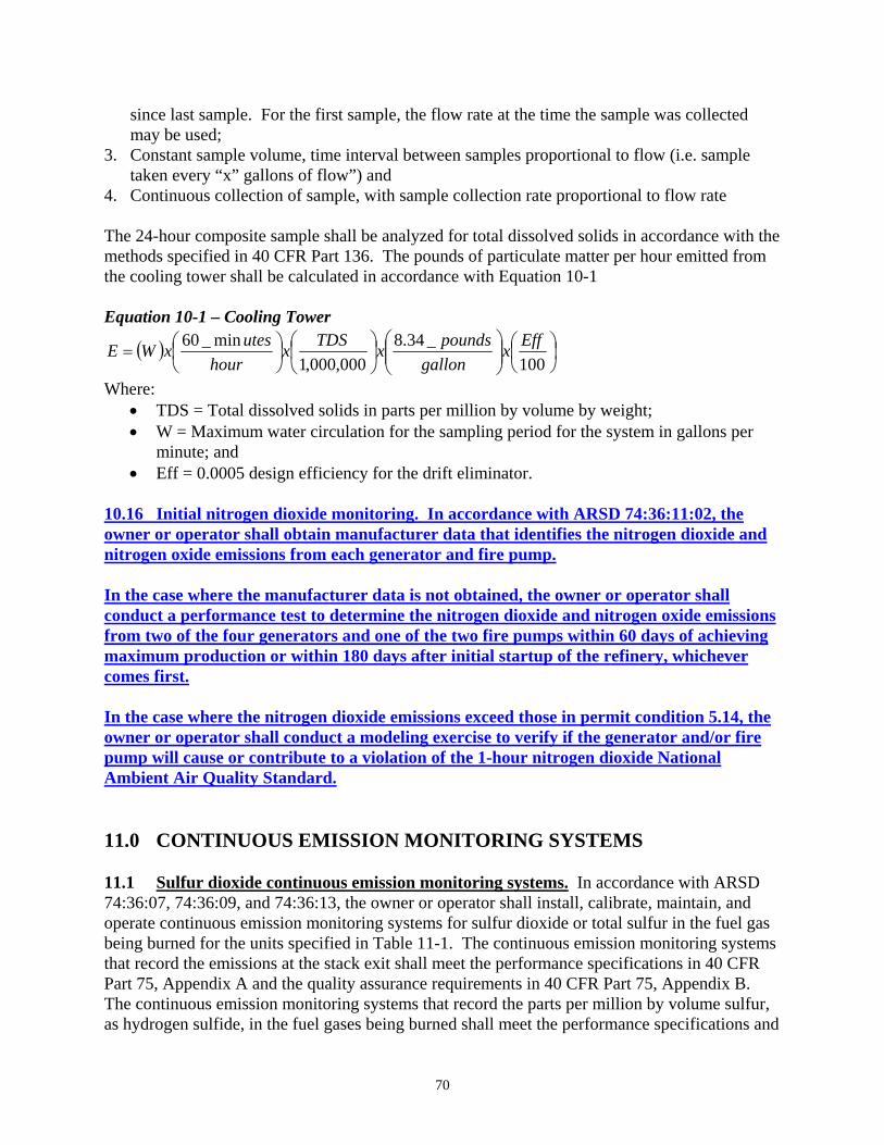
since last sample. For the first sample, the flow rate at the time the sample was collected may be used;
3. Constant sample volume, time interval between samples proportional to flow (i.e. sample taken every “x” gallons of flow”) and
4. Continuous collection of sample, with sample collection rate proportional to flow rate The 24-hour composite sample shall be analyzed for total dissolved solids in accordance with the methods specified in 40 CFR Part 136. The pounds of particulate matter per hour emitted from the cooling tower shall be calculated in accordance with Equation 10-1 Equation 10-1 – Cooling Tower
( ) ⎟⎠⎞
⎜⎝⎛
⎟⎟⎠
⎞⎜⎜⎝
⎛⎟⎠
⎞⎜⎝
⎛⎟⎠⎞
⎜⎝⎛=
100_34.8
000,000,1min_60 Effx
gallonpoundsxTDSx
hourutesxWE
Where: • TDS = Total dissolved solids in parts per million by volume by weight; • W = Maximum water circulation for the sampling period for the system in gallons per
minute; and • Eff = 0.0005 design efficiency for the drift eliminator.
10.16 Initial nitrogen dioxide monitoring. In accordance with ARSD 74:36:11:02, the owner or operator shall obtain manufacturer data that identifies the nitrogen dioxide and nitrogen oxide emissions from each generator and fire pump. In the case where the manufacturer data is not obtained, the owner or operator shall conduct a performance test to determine the nitrogen dioxide and nitrogen oxide emissions from two of the four generators and one of the two fire pumps within 60 days of achieving maximum production or within 180 days after initial startup of the refinery, whichever comes first. In the case where the nitrogen dioxide emissions exceed those in permit condition 5.14, the owner or operator shall conduct a modeling exercise to verify if the generator and/or fire pump will cause or contribute to a violation of the 1-hour nitrogen dioxide National Ambient Air Quality Standard. 11.0 CONTINUOUS EMISSION MONITORING SYSTEMS 11.1 Sulfur dioxide continuous emission monitoring systems. In accordance with ARSD 74:36:07, 74:36:09, and 74:36:13, the owner or operator shall install, calibrate, maintain, and operate continuous emission monitoring systems for sulfur dioxide or total sulfur in the fuel gas being burned for the units specified in Table 11-1. The continuous emission monitoring systems that record the emissions at the stack exit shall meet the performance specifications in 40 CFR Part 75, Appendix A and the quality assurance requirements in 40 CFR Part 75, Appendix B. The continuous emission monitoring systems that record the parts per million by volume sulfur, as hydrogen sulfide, in the fuel gases being burned shall meet the performance specifications and
70
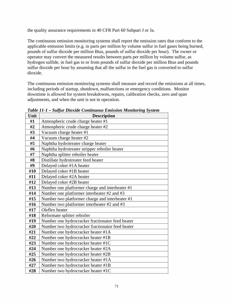
the quality assurance requirements in 40 CFR Part 60 Subpart J or Ja. The continuous emission monitoring systems shall report the emission rates that conform to the applicable emission limits (e.g. in parts per million by volume sulfur in fuel gases being burned, pounds of sulfur dioxide per million Btus, pounds of sulfur dioxide per hour). The owner or operator may convert the measured results between parts per million by volume sulfur, as hydrogen sulfide, in fuel gas to or from pounds of sulfur dioxide per million Btus and pounds sulfur dioxide per hour by assuming that all the sulfur in the fuel gas is converted to sulfur dioxide. The continuous emission monitoring systems shall measure and record the emissions at all times, including periods of startup, shutdown, malfunctions or emergency conditions. Monitor downtime is allowed for system breakdowns, repairs, calibration checks, zero and span adjustments, and when the unit is not in operation. Table 11-1 – Sulfur Dioxide Continuous Emission Monitoring System Unit Description #1 Atmospheric crude charge heater #1 #2 Atmospheric crude charge heater #2 #3 Vacuum charge heater #1 #4 Vacuum charge heater #2 #5 Naphtha hydrotreater charge heater #6 Naphtha hydrotreater stripper reboiler heater #7 Naphtha splitter reboiler heater #8 Distillate hydrotreater feed heater #9 Delayed coker #1A heater #10 Delayed coker #1B heater #11 Delayed coker #2A heater #12 Delayed coker #2B heater #13 Number one platformer charge and interheater #1 #14 Number one platformer interheater #2 and #3 #15 Number two platformer charge and interheater #1 #16 Number two platformer interheater #2 and #3 #17 Oleflex heater #18 Reformate splitter reboiler #19 Number one hydrocracker fractionator feed heater #20 Number two hydrocracker fractionator feed heater #21 Number one hydrocracker heater #1A #22 Number one hydrocracker heater #1B #23 Number one hydrocracker heater #1C #24 Number one hydrocracker heater #2A #25 Number one hydrocracker heater #2B #26 Number two hydrocracker heater #1A #27 Number two hydrocracker heater #1B #28 Number two hydrocracker heater #1C
71

Unit Description #29 Number two hydrocracker heater #2A #30 Number two hydrocracker heater #2B #42a Sulfur recovery plant thermal oxidizer #1 #42b Sulfur recovery plant thermal oxidizer #2 #42c Sulfur recovery plant thermal oxidizer #3 #42d Sulfur recovery plant thermal oxidizer #4 #42e Sulfur recovery plant thermal oxidizer #5 #42f Sulfur recovery plant thermal oxidizer #6 #45a Wastewater treatment plant catalytic oxidizer #60 Combined cycle gas turbine #1 #61 Combined cycle gas turbine #2 #62 Combined cycle gas turbine #3 #63 Combined cycle gas turbine #4 #64 Combined cycle gas turbine #5 #175 Tank farm thermal oxidizer #176 Tank farm thermal oxidizer 11.2 Nitrogen oxide continuous emission monitoring systems. In accordance with ARSD 74:36:07, 74:36:09, and 74:36:13, the owner or operator shall install, calibrate, maintain, and operate continuous emission monitoring systems for nitrogen oxide for the units specified in Table 11-2. The continuous emission monitoring systems shall report the emission rates in pounds per million Btus and pounds per hour. The continuous emission monitoring systems shall measure and record the emissions at all times, including periods of startup, shutdown, malfunctions or emergency conditions. Monitor downtime is allowed for system breakdowns, repairs, calibration checks, zero and span adjustments, and when the unit is not in operation. The continuous emission monitoring systems shall meet the performance specifications in 40 CFR Part 75, Appendix A and the quality assurance requirements in 40 CFR Part 75, Appendix B. Table 11-2 – Nitrogen Oxide Continuous Emission Monitoring System Unit Description #1 Atmospheric crude charge heater #1 #2 Atmospheric crude charge heater #2 #3 Vacuum charge heater #1 #4 Vacuum charge heater #2 #5 Naphtha hydrotreater charge heater #6 Naphtha hydrotreater stripper reboiler heater #7 Naphtha splitter reboiler heater #8 Distillate hydrotreater feed heater #9 Delayed coker #1A heater #10 Delayed coker #1B heater #11 Delayed coker #2A heater #12 Delayed coker #2B heater #13 Number one platformer charge and interheater #1 #14 Number one platformer interheater #2 and #3
72
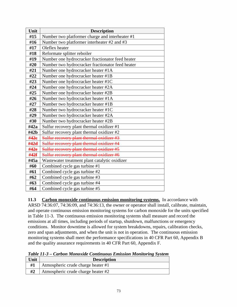
Unit Description #15 Number two platformer charge and interheater #1 #16 Number two platformer interheater #2 and #3 #17 Oleflex heater #18 Reformate splitter reboiler #19 Number one hydrocracker fractionator feed heater #20 Number two hydrocracker fractionator feed heater #21 Number one hydrocracker heater #1A #22 Number one hydrocracker heater #1B #23 Number one hydrocracker heater #1C #24 Number one hydrocracker heater #2A #25 Number one hydrocracker heater #2B #26 Number two hydrocracker heater #1A #27 Number two hydrocracker heater #1B #28 Number two hydrocracker heater #1C #29 Number two hydrocracker heater #2A #30 Number two hydrocracker heater #2B #42a Sulfur recovery plant thermal oxidizer #1 #42b Sulfur recovery plant thermal oxidizer #2 #42c Sulfur recovery plant thermal oxidizer #3 #42d Sulfur recovery plant thermal oxidizer #4 #42e Sulfur recovery plant thermal oxidizer #5 #42f Sulfur recovery plant thermal oxidizer #6 #45a Wastewater treatment plant catalytic oxidizer #60 Combined cycle gas turbine #1 #61 Combined cycle gas turbine #2 #62 Combined cycle gas turbine #3 #63 Combined cycle gas turbine #4 #64 Combined cycle gas turbine #5
11.3 Carbon monoxide continuous emission monitoring systems. In accordance with ARSD 74:36:07, 74:36:09, and 74:36:13, the owner or operator shall install, calibrate, maintain, and operate continuous emission monitoring systems for carbon monoxide for the units specified in Table 11-3. The continuous emission monitoring systems shall measure and record the emissions at all times, including periods of startup, shutdown, malfunctions or emergency conditions. Monitor downtime is allowed for system breakdowns, repairs, calibration checks, zero and span adjustments, and when the unit is not in operation. The continuous emission monitoring systems shall meet the performance specifications in 40 CFR Part 60, Appendix B and the quality assurance requirements in 40 CFR Part 60, Appendix F. Table 11-3 – Carbon Monoxide Continuous Emission Monitoring System Unit Description #1 Atmospheric crude charge heater #1 #2 Atmospheric crude charge heater #2
73
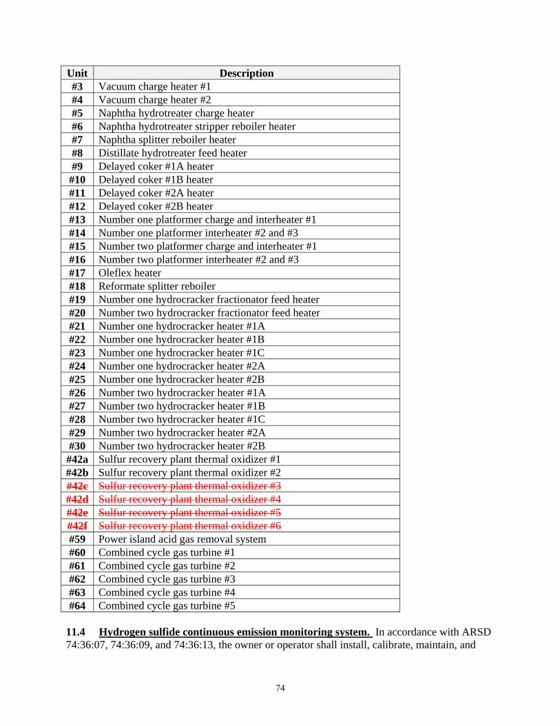
Unit Description #3 Vacuum charge heater #1 #4 Vacuum charge heater #2 #5 Naphtha hydrotreater charge heater #6 Naphtha hydrotreater stripper reboiler heater #7 Naphtha splitter reboiler heater #8 Distillate hydrotreater feed heater #9 Delayed coker #1A heater #10 Delayed coker #1B heater #11 Delayed coker #2A heater #12 Delayed coker #2B heater #13 Number one platformer charge and interheater #1 #14 Number one platformer interheater #2 and #3 #15 Number two platformer charge and interheater #1 #16 Number two platformer interheater #2 and #3 #17 Oleflex heater #18 Reformate splitter reboiler #19 Number one hydrocracker fractionator feed heater #20 Number two hydrocracker fractionator feed heater #21 Number one hydrocracker heater #1A #22 Number one hydrocracker heater #1B #23 Number one hydrocracker heater #1C #24 Number one hydrocracker heater #2A #25 Number one hydrocracker heater #2B #26 Number two hydrocracker heater #1A #27 Number two hydrocracker heater #1B #28 Number two hydrocracker heater #1C #29 Number two hydrocracker heater #2A #30 Number two hydrocracker heater #2B #42a Sulfur recovery plant thermal oxidizer #1 #42b Sulfur recovery plant thermal oxidizer #2 #42c Sulfur recovery plant thermal oxidizer #3 #42d Sulfur recovery plant thermal oxidizer #4 #42e Sulfur recovery plant thermal oxidizer #5 #42f Sulfur recovery plant thermal oxidizer #6 #59 Power island acid gas removal system #60 Combined cycle gas turbine #1 #61 Combined cycle gas turbine #2 #62 Combined cycle gas turbine #3 #63 Combined cycle gas turbine #4 #64 Combined cycle gas turbine #5
11.4 Hydrogen sulfide continuous emission monitoring system. In accordance with ARSD 74:36:07, 74:36:09, and 74:36:13, the owner or operator shall install, calibrate, maintain, and
74
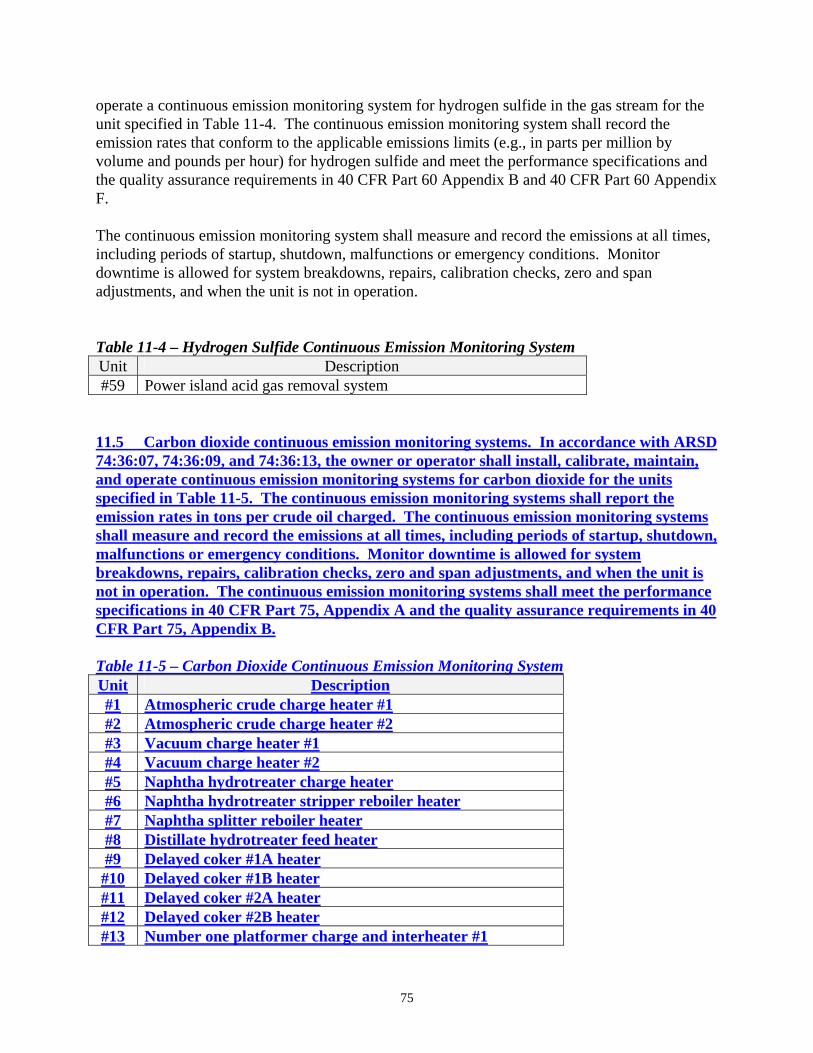
operate a continuous emission monitoring system for hydrogen sulfide in the gas stream for the unit specified in Table 11-4. The continuous emission monitoring system shall record the emission rates that conform to the applicable emissions limits (e.g., in parts per million by volume and pounds per hour) for hydrogen sulfide and meet the performance specifications and the quality assurance requirements in 40 CFR Part 60 Appendix B and 40 CFR Part 60 Appendix F. The continuous emission monitoring system shall measure and record the emissions at all times, including periods of startup, shutdown, malfunctions or emergency conditions. Monitor downtime is allowed for system breakdowns, repairs, calibration checks, zero and span adjustments, and when the unit is not in operation. Table 11-4 – Hydrogen Sulfide Continuous Emission Monitoring System Unit Description #59 Power island acid gas removal system
11.5 Carbon dioxide continuous emission monitoring systems. In accordance with ARSD 74:36:07, 74:36:09, and 74:36:13, the owner or operator shall install, calibrate, maintain, and operate continuous emission monitoring systems for carbon dioxide for the units specified in Table 11-5. The continuous emission monitoring systems shall report the emission rates in tons per crude oil charged. The continuous emission monitoring systems shall measure and record the emissions at all times, including periods of startup, shutdown, malfunctions or emergency conditions. Monitor downtime is allowed for system breakdowns, repairs, calibration checks, zero and span adjustments, and when the unit is not in operation. The continuous emission monitoring systems shall meet the performance specifications in 40 CFR Part 75, Appendix A and the quality assurance requirements in 40 CFR Part 75, Appendix B. Table 11-5 – Carbon Dioxide Continuous Emission Monitoring System Unit Description #1 Atmospheric crude charge heater #1 #2 Atmospheric crude charge heater #2 #3 Vacuum charge heater #1 #4 Vacuum charge heater #2 #5 Naphtha hydrotreater charge heater #6 Naphtha hydrotreater stripper reboiler heater #7 Naphtha splitter reboiler heater #8 Distillate hydrotreater feed heater #9 Delayed coker #1A heater #10 Delayed coker #1B heater #11 Delayed coker #2A heater #12 Delayed coker #2B heater #13 Number one platformer charge and interheater #1
75

Unit Description #14 Number one platformer interheater #2 and #3 #15 Number two platformer charge and interheater #1 #16 Number two platformer interheater #2 and #3 #17 Oleflex heater #18 Reformate splitter reboiler #19 Number one hydrocracker fractionator feed heater #20 Number two hydrocracker fractionator feed heater #21 Number one hydrocracker heater #1A #22 Number one hydrocracker heater #1B #23 Number one hydrocracker heater #1C #24 Number one hydrocracker heater #2A #25 Number one hydrocracker heater #2B #26 Number two hydrocracker heater #1A #27 Number two hydrocracker heater #1B #28 Number two hydrocracker heater #1C #29 Number two hydrocracker heater #2A #30 Number two hydrocracker heater #2B #59 Power island acid gas removal system #60 Combined cycle gas turbine #1 #61 Combined cycle gas turbine #2 #62 Combined cycle gas turbine #3 #63 Combined cycle gas turbine #4 #64 Combined cycle gas turbine #5
12.0 REFINERY FLARE WORK PRACTICE STANDARDS 12.1 Refinery flare operations. In accordance with ARSD 74:36:09:02, as referenced to ARSD 74:36:05:16.01(8), the owner or operator shall not flare the gases from the refinery, except during a malfunction. Malfunction means any sudden and unavoidable failure of air pollution control equipment, process equipment, or a process to operate in a normal or usual manner. A failure caused entirely or in part by poor maintenance, careless operation, preventable equipment breakdown, or any other cause within the control of the owner or operator of the source is not a malfunction. The flaring of gases from the refinery during a malfunction shall be completed in accordance with a flare minimization plan. 12.2 Refinery flare design. In accordance with ARSD 74:36:09:02, as referenced to ARSD 74:36:05:16.01(8), the owner or operator shall meet the design and operational requirements of 40 CFR 60.18. 12.3 Refinery flare minimization plan. In accordance with ARSD 74:36:09:02, as referenced to ARSD 74:36:05:16.01(8), the owner or operator shall develop, maintain, and implement a written Refinery Flare Minimization plan. The Refinery Flare Minimization plan
76
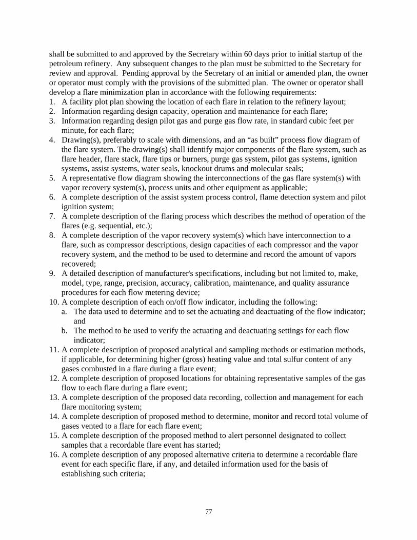
shall be submitted to and approved by the Secretary within 60 days prior to initial startup of the petroleum refinery. Any subsequent changes to the plan must be submitted to the Secretary for review and approval. Pending approval by the Secretary of an initial or amended plan, the owner or operator must comply with the provisions of the submitted plan. The owner or operator shall develop a flare minimization plan in accordance with the following requirements: 1. A facility plot plan showing the location of each flare in relation to the refinery layout; 2. Information regarding design capacity, operation and maintenance for each flare; 3. Information regarding design pilot gas and purge gas flow rate, in standard cubic feet per
minute, for each flare; 4. Drawing(s), preferably to scale with dimensions, and an “as built” process flow diagram of
the flare system. The drawing(s) shall identify major components of the flare system, such as flare header, flare stack, flare tips or burners, purge gas system, pilot gas systems, ignition systems, assist systems, water seals, knockout drums and molecular seals;
5. A representative flow diagram showing the interconnections of the gas flare system(s) with vapor recovery system(s), process units and other equipment as applicable;
6. A complete description of the assist system process control, flame detection system and pilot ignition system;
7. A complete description of the flaring process which describes the method of operation of the flares (e.g. sequential, etc.);
8. A complete description of the vapor recovery system(s) which have interconnection to a flare, such as compressor descriptions, design capacities of each compressor and the vapor recovery system, and the method to be used to determine and record the amount of vapors recovered;
9. A detailed description of manufacturer's specifications, including but not limited to, make, model, type, range, precision, accuracy, calibration, maintenance, and quality assurance procedures for each flow metering device;
10. A complete description of each on/off flow indicator, including the following: a. The data used to determine and to set the actuating and deactuating of the flow indicator;
and b. The method to be used to verify the actuating and deactuating settings for each flow
indicator; 11. A complete description of proposed analytical and sampling methods or estimation methods,
if applicable, for determining higher (gross) heating value and total sulfur content of any gases combusted in a flare during a flare event;
12. A complete description of proposed locations for obtaining representative samples of the gas flow to each flare during a flare event;
13. A complete description of the proposed data recording, collection and management for each flare monitoring system;
14. A complete description of proposed method to determine, monitor and record total volume of gases vented to a flare for each flare event;
15. A complete description of the proposed method to alert personnel designated to collect samples that a recordable flare event has started;
16. A complete description of any proposed alternative criteria to determine a recordable flare event for each specific flare, if any, and detailed information used for the basis of establishing such criteria;
77
17. A complete description of the methods to determine emissions associated with recordable events during periods when the flare monitoring system is out of service;
18. Description and evaluation of prevention measures to address the following: a. Flaring that has occurred or reasonably may be expected to occur during planned major
maintenance activities, including startup and shutdown. The evaluation shall include a review of flaring that has occurred during these activities in the past five years and shall consider the feasibility of performing these activities without flaring;
b. Flaring that may reasonably be expected to occur due to issues of gas quantity and quality. The evaluation shall include an audit of the storage capacity available for excess vent gases, the scrubbing capacity available for vent gases including any limitations associated with scrubbing the vent gases for use as a fuel, and shall consider the feasibility of reducing flaring through the recovery, treatment, and use of the gas or other means; and
c. Flaring caused by the recent failure of air pollution control equipment, process equipment, or a process to operate in a normal or usual manner. The evaluation shall consider the adequacy of existing maintenance schedules and protocols for such equipment. For purposes of this section, a failure is recurrent if it occurs more than twice in any five year period as a result of the same causes as identified in the event-specific investigations;
19. A program of corrective action for malfunctioning process, air pollution control, and monitoring equipment related to the performance of flares;
20. Procedures for conducting a root cause analysis; and 21. The methods for estimating particulate matter, sulfur dioxide, nitrogen oxide, volatile
organic compound, and carbon monoxide emissions during a flaring event. The owner or operator shall review and revise, if applicable, the flare minimization plan once per calendar year to ensure the plan remains current and complies with the above requirements. 12.4 Refinery flare recordkeeping and reporting. In accordance with ARSD 74:36:09:02, as referenced to ARSD 74:36:05:16.01(8), the owner or operator shall record the following during each flare event: 1. Identify and record the date and time that the flare event started and the duration of the flare
event; 2. Within 15 minutes after the start of the flare event, submit notification to the Secretary,
indicating (based on available information) the cause of the flare event, the process system(s) involved, and the anticipated duration of the flare event;
3. Measure and record the gas flow to each flare, using continuous flow monitoring devices; 4. Beginning no more than 15 minutes after the start of the flare event, perform a visible
emissions observation for the duration of the flare event, using 40 CFR Part 60, Appendix A, Method 9. Visible emissions observations are not required between sunset and sunrise or during other periods when valid observations using Method 9 are not possible;
5. Take a representative sample of the gas flow to each flare; 6. Determine and record the higher (gross) heating value of the gas flow to each flare; 7. Determine and record the total sulfur content of the gas flow to each flare; 8. Calculate and record the particulate matter, sulfur dioxide, nitrogen oxide, volatile organic
compounds, and carbon monoxide emissions from the flare during the flare event; and
78

9. Within 24 hours after the end of the flare event, submit notification to the Secretary, summarizing all information required to be recorded in steps 1 through 9 (based on available information).
12.5 Root cause analysis, recordkeeping and reporting. In accordance with ARSD 74:36:09:02, as referenced to ARSD 74:36:05:16.01(8), the owner or operator shall conduct a root cause analysis of flaring event that exceeds 5,000 standard cubic foot of gas and report the findings of the root cause analysis to the Secretary within 45 days after the flaring event. The natural gas fired in the pilot flame does not count toward the 5,000 standard cubic foot criteria. The root cause analysis and report shall contain the following: 1. The date and time that the flaring event started and ended; 2. The total quantity of gas flared during each event; 3. The quantity of particulate matter, sulfur dioxide, nitrogen oxide, volatile organic
compounds, and carbon monoxide emissions emitted and the calculations used to determine the quantities;
4. The steps taken to limit the duration of the flaring event or the quantity of emissions associated with the event;
5. A detailed analysis that sets forth the root cause and all significant contributing causes of the flaring event to the extent determinable;
6. An analysis of the measures, if any, available to reduce the likelihood of a recurrence of a flaring event resulting from the same root cause or significant contributing causes in the future;
7. A demonstration that the actions taken during the flaring event are consistent with the procedures specified in the flare minimization plan, as appropriate. If the actions taken during the flaring event are not consistent with the procedures specified in the appropriate plan, then the owner or operator must record the actions taken for that event and identify the reasons why the plan was not followed;
8. A demonstration that flaring was caused by a sudden, unavoidable breakdown of technology, beyond the control of the owner or operator. The flaring emissions did not occur due to any activity or event that could have been foreseen and avoided, or planned for, and could not have been avoided by better operation and maintenance activities;
9. A demonstration that repairs were made in an expeditious fashion when the owner or operator knew or should have know that a malfunction was occurring; and
10. A demonstration that the flaring emissions were not due to a recurring pattern indicative of inadequate design, operating, and maintenance.
13.0 IGCC FLARE WORK PRACTICE STANDARDS 13.1 IGCC flare operations. In accordance with ARSD 74:36:09:02, as referenced to ARSD 74:36:05:16.01(8), the owner or operator shall develop, maintain, and implement a written IGCC Flare Minimization plan. The IGCC Flare Minimization plan shall be submitted to and approved by the Secretary within 60 days prior to initial startup of the petroleum refinery. Any subsequent changes to the plan must be submitted to the Secretary for review and approval. Pending approval by the Secretary of an initial or amended plan, the owner or operator must comply with
79
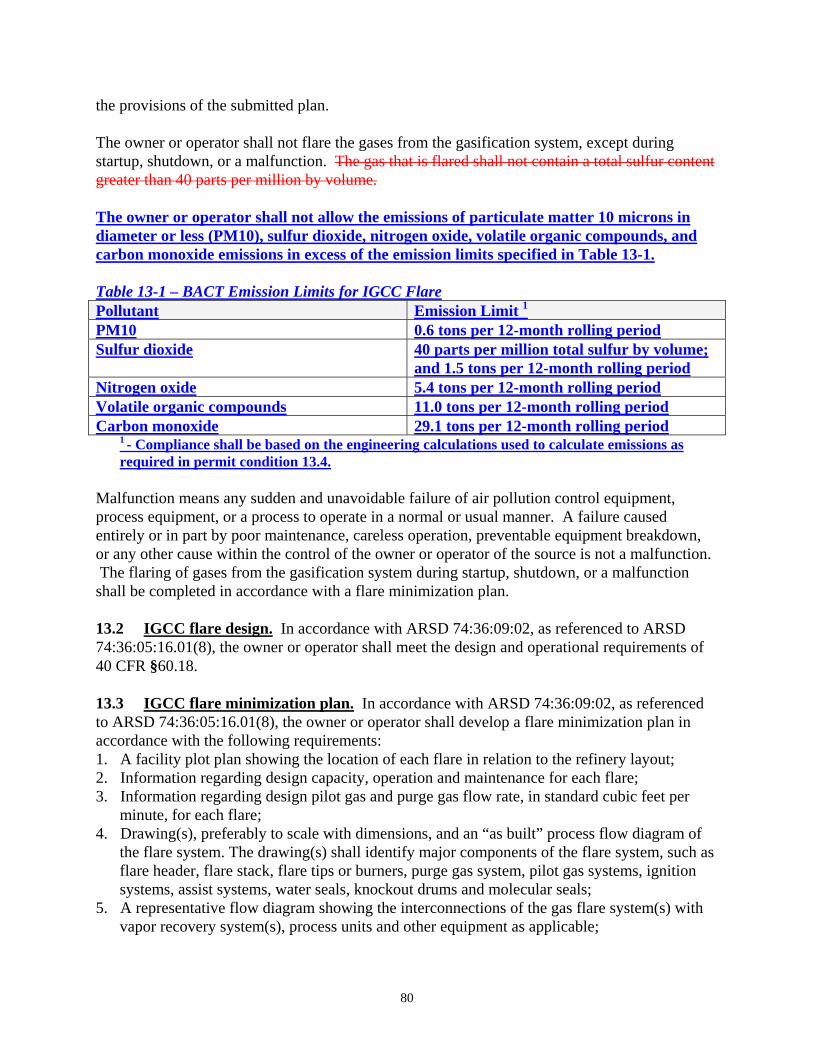
the provisions of the submitted plan. The owner or operator shall not flare the gases from the gasification system, except during startup, shutdown, or a malfunction. The gas that is flared shall not contain a total sulfur content greater than 40 parts per million by volume. The owner or operator shall not allow the emissions of particulate matter 10 microns in diameter or less (PM10), sulfur dioxide, nitrogen oxide, volatile organic compounds, and carbon monoxide emissions in excess of the emission limits specified in Table 13-1. Table 13-1 – BACT Emission Limits for IGCC Flare Pollutant Emission Limit 1 PM10 0.6 tons per 12-month rolling period Sulfur dioxide 40 parts per million total sulfur by volume;
and 1.5 tons per 12-month rolling period Nitrogen oxide 5.4 tons per 12-month rolling period Volatile organic compounds 11.0 tons per 12-month rolling period Carbon monoxide 29.1 tons per 12-month rolling period
1 - Compliance shall be based on the engineering calculations used to calculate emissions as required in permit condition 13.4.
Malfunction means any sudden and unavoidable failure of air pollution control equipment, process equipment, or a process to operate in a normal or usual manner. A failure caused entirely or in part by poor maintenance, careless operation, preventable equipment breakdown, or any other cause within the control of the owner or operator of the source is not a malfunction. The flaring of gases from the gasification system during startup, shutdown, or a malfunction shall be completed in accordance with a flare minimization plan. 13.2 IGCC flare design. In accordance with ARSD 74:36:09:02, as referenced to ARSD 74:36:05:16.01(8), the owner or operator shall meet the design and operational requirements of 40 CFR §60.18. 13.3 IGCC flare minimization plan. In accordance with ARSD 74:36:09:02, as referenced to ARSD 74:36:05:16.01(8), the owner or operator shall develop a flare minimization plan in accordance with the following requirements: 1. A facility plot plan showing the location of each flare in relation to the refinery layout; 2. Information regarding design capacity, operation and maintenance for each flare; 3. Information regarding design pilot gas and purge gas flow rate, in standard cubic feet per
minute, for each flare; 4. Drawing(s), preferably to scale with dimensions, and an “as built” process flow diagram of
the flare system. The drawing(s) shall identify major components of the flare system, such as flare header, flare stack, flare tips or burners, purge gas system, pilot gas systems, ignition systems, assist systems, water seals, knockout drums and molecular seals;
5. A representative flow diagram showing the interconnections of the gas flare system(s) with vapor recovery system(s), process units and other equipment as applicable;
80
6. A complete description of the assist system process control, flame detection system and pilot ignition system;
7. A complete description of the flaring process which describes the method of operation of the flares (e.g. sequential, etc.);
8. A complete description of the vapor recovery system(s) which have interconnection to a flare, such as compressor descriptions, design capacities of each compressor and the vapor recovery system, and the method to be used to determine and record the amount of vapors recovered;
9. A detailed description of manufacturer's specifications, including but not limited to, make, model, type, range, precision, accuracy, calibration, maintenance, and quality assurance procedures for each flow metering device;
10. A complete description of each on/off flow indicator, including the following: a. The data used to determine and to set the actuating and deactuating of the flow indicator;
and b. The method to be used to verify the actuating and deactuating settings for each flow
indicator; 11. A complete description of proposed analytical and sampling methods or estimation methods,
if applicable, for determining higher (gross) heating value and total sulfur content of any gases combusted in a flare during a flare event;
12. A complete description of proposed locations for obtaining representative samples of the gas flow to each flare during a flare event;
13. A complete description of the proposed data recording, collection and management for each flare monitoring system;
14. A complete description of proposed method to determine, monitor and record total volume of gases vented to a flare for each flare event;
15. A complete description of the proposed method to alert personnel designated to collect samples that a recordable flare event has started;
16. A complete description of any proposed alternative criteria to determine a recordable flare event for each specific flare, if any, and detailed information used for the basis of establishing such criteria;
17. A complete description of the methods to determine emissions associated with recordable events during periods when the flare monitoring system is out of service;
18. Description and evaluation of prevention measures to address flaring caused by the recent failure of air pollution control equipment, process equipment, or a process to operate in a normal or usual manner. The evaluation shall consider the adequacy of existing maintenance schedules and protocols for such equipment. For purposes of this section, a failure is recurrent if it occurs more than twice in any five year period as a result of the same causes as identified in the event-specific investigations;
19. A program of corrective action for malfunctioning process, air pollution control, and monitoring equipment related to the performance of flares; and
20. The methods for estimating particulate matter, sulfur dioxide, nitrogen oxide, volatile organic compound, and carbon monoxide emissions during a flaring event.
The owner or operator shall review and revise, if applicable, the flare minimization plan once per calendar year to ensure the plan remains current and complies with the above requirements.
81
13.4 IGCC flare recordkeeping and reporting. In accordance with ARSD 74:36:09:02, as referenced to ARSD 74:36:05:16.01(8), the owner or operator shall record the following during each flare event: 1. Identify and record the date and time that the flare event started and the duration of the flare
event; 2. Within 15 minutes after the start of the flare event, submit notification to the Secretary,
indicating (based on available information) the cause of the flare event, the process system(s) involved, and the anticipated duration of the flare event;
3. Measure and record the gas flow to each flare, using continuous flow monitoring devices; 4. Beginning no more than 15 minutes after the start of the flare event, perform a visible
emissions observation for the duration of the flare event, using 40 CFR Part 60, Appendix A, Method 9. Visible emissions observations are not required between sunset and sunrise or during other periods when valid observations using Method 9 are not possible;
5. Take a representative sample of the gas flow to each flare; 6. Determine and record the higher (gross) heating value of the gas flow to each flare; 7. Determine and record the total sulfur content of the gas flow to each flare; 8. Calculate and record the particulate matter, sulfur dioxide, nitrogen oxide, volatile organic
compounds, and carbon monoxide emissions from the flare during the flare event; 9. Calculate the monthly particulate matter, sulfur dioxide, nitrogen oxide, volatile
organic compounds, and carbon monoxide emissions from the flares each month and the 12-month rolling total for each month;
10. Identify the reason or cause of the flaring, such as due to startup, shutdown, or a malfunction; and
11. Within 24 hours after the end of the flare event, submit notification to the Secretary, summarizing all information required to be recorded in steps 1 through 10 (based on available information).
13.5 Root cause analysis, recordkeeping and reporting. In accordance with ARSD 74:36:09:02, as referenced to ARSD 74:36:05:16.01(8), the owner or operator shall conduct a root cause analysis of flaring event caused by a malfunction that exceeds 5,000 standard cubic foot of gas and report the findings of the root cause analysis to the Secretary within 45 days after the flaring event. The natural gas fired in the pilot flame or the flaring during startup and shutdown does not count toward the 5,000 standard cubic foot criteria. The root cause analysis and report shall contain the following: 1. The date and time that the flaring event started and ended; 2. The total quantity of gas flared during each event; 3. The quantity of particulate matter, sulfur dioxide, nitrogen oxide, volatile organic
compounds, and carbon monoxide emissions emitted and the calculations used to determine the quantities;
4. The steps taken to limit the duration of the flaring event or the quantity of emissions associated with the event;
5. A detailed analysis that sets forth the root cause and all significant contributing causes of the flaring event to the extent determinable;
6. An analysis of the measures, if any, available to reduce the likelihood of a recurrence of a flaring event resulting from the same root cause or significant contributing causes in the future;
82
7. A demonstration that the actions taken during the flaring event are consistent with the procedures specified in the flare minimization plan, as appropriate. If the actions taken during the flaring event are not consistent with the procedures specified in the appropriate plan, then the owner or operator must record the actions taken for that event and identify the reasons why the plan was not followed;
8. A demonstration that flaring was caused by a sudden, unavoidable breakdown of technology, beyond the control of the owner or operator. The flaring emissions did not occur due to any activity or event that could have been foreseen and avoided, or planned for, and could not have been avoided by better operation and maintenance activities;
9. A demonstration that repairs were made in an expeditious fashion when the operator knew or should have know that a malfunction was occurring; and
10. A demonstration that the flaring emissions were not due to a recurring pattern indicative of inadequate design, operating, and maintenance.
14.0 LDAR PROGRAM 14.1 LDAR applicability. In accordance with ARSD 74:36:09:02, as referenced to 40 CFR §52.21(j)(3), the equipment that is applicable to conditions 14.2 through 14.13 are those in organic hazardous air pollutant service, in volatile organic compound service, and/or in greenhouse gas service. Greenhouse gas service means a piece of equipment that contains a fluid (gas or liquid) that is at least 5 percent by weight of methane. The remaining definitions that apply to the leak and detection program are those in 40 CFR § 63.161. 14.2 Periodic monitoring of pumps in light liquid service. In accordance with ARSD 74:36:09:02, as referenced to 40 CFR §52.21(j)(3), the owner or operator shall periodically monitor each pump in light liquid service to detect leaks as follows: 1. Each pump in light liquid service shall be monitored each calendar month to detect leaks by
the method specified in 40 CFR §63.180. A leak is detected if an instrument reading of 500 parts per million or greater is measured;
2. Each pump shall be checked by visual inspection each calendar week. A leak is detected if there is indications of liquid drippings from the pump seal;
3. When a leak is detected; a first attempt at repairing the leak shall be completed within 24 hours of detecting the leak. The first attempt at the repair may include, but are not limited to: tightening of packing gland nuts and ensuring that the seal flush is operating at design pressure and temperature. The leak shall be successfully repaired within 7 days of detecting the leak except for as provided in permit condition 14.12 14-13;
4. Within 24 hours after the attempt to repair the leak has been completed, another reading based on the method that determined the leak shall be made to verify if the leak has been repaired.
5. Each pump equipped with a dual mechanical seal system that includes a barrier fluid system is exempt from steps 1and 2 provided the following requirements in steps 5a through 5d are met:
83
a. Each dual mechanical seal system is i. Operated with a barrier fluid at a pressure that is at all times greater than the
pump stuffing box pressure; or ii. Equipped with a barrier fluid degassing reservoir that is routed to a fuel gas
system or connected by a closed-vent system to a control device that complies with permit condition 14.9 14.10; or
iii. Equipped with a closed-loop system that purges the barrier fluid into a process stream; and
b. The barrier fluid is not in light liquid service; c. Each barrier fluid system is equipped with a sensor that will detect failure of the seal
system, the barrier fluid system, or both. The sensor shall be observed daily or equipped with an alarm. Based on design considerations, a leak is detected if the established criteria for the sensor are triggered. The criteria established for the sensor shall be equivalent to monitoring a leak at 500 parts per million;
d. Each pump shall be checked by visual inspection each calendar week. Based on design considerations, a leak is detected if the established criteria for the liquid drippings from the pump seal are exceeded. The criteria established for the sensor shall be equivalent to monitoring a leak at 500 parts per million. If there are indications of liquid drippings from the pump seal is less than the design criteria, the pump shall be monitored to detect leaks by the method specified in 40 CFR §63.180. A leak is detected if an instrument reading of 500 parts per million or greater is measured;
6. Each pump that is designed with no externally actuated shaft penetrating the pump housing is exempt from steps 1, 2, and 3.
7. Each pump that is equipped with a closed vent system capable of capturing and transporting any leakage from the seal or seals to a process or to a fuel gas system or to a control device that complies with permit condition 14.9 14.10 is exempt from steps 1, 2, and 3.
14.3 Periodic monitoring of compressors. In accordance with ARSD 74:36:09:02, as referenced to 40 CFR §52.21(j)(3), the owner or operator shall periodically monitor each compressor to detect leaks as follows 1. Each compressor shall be monitored each calendar month to detect leaks by the method
specified in 40 CFR §63.180. A leak is detected if an instrument reading of 500 parts per million or greater is measured;
2. When a leak is detected; a first attempt at repairing the leak shall be completed within 24 hours of detecting the leak. The leak shall be successfully repaired within 7 days of detecting the leak except for as provided in permit condition 14.12 14-13;
3. Each compressor shall be equipped with a seal system that includes a barrier fluid system and that prevents leakage of process fluid to the atmosphere is exempt from step 1. a. Each compressor system shall meet one of the following requirements
i. Operated with a barrier fluid at a pressure that is at all times greater than the compressor stuffing box pressure; or
ii. Equipped with a barrier fluid degassing reservoir that is routed to a fuel gas system or connected by a closed-vent system to a control device that complies with permit condition 14.9 14.10; or
84
iii. Equipped with a closed-loop system that purges the barrier fluid into a process stream; and
b. The barrier fluid is not in light liquid service; c. Each barrier fluid system is equipped with a sensor that will detect failure of the seal
system, the barrier fluid system, or both. The sensor shall be observed daily or equipped with an alarm. Based on design considerations, a leak is detected if the established criteria for the sensor are triggered. The criteria established for the sensor shall be equivalent to monitoring a leak at 500 parts per million;
4. Each compressor that is equipped with a closed vent system capable of capturing and transporting any leakage from the compressor draft shaft seal to a process or to a fuel gas system or to a control device that complies with permit condition 14.9 14.10 is exempt from steps 1, 2, and 3; and
5. Within 24 hours after the attempt to repair the leak has been completed, another reading based on the method that determined the leak shall be made to verify if the leak has been repaired.
14.4 Periodic monitoring of pressure relief devices in gas/vapor service. In accordance with ARSD 74:36:09:02, as referenced to 40 CFR §52.21(j)(3), the owner or operator shall periodically monitor each pressure relief devices in gas/vapor service to detect leaks as follows: 1. Each pressure relief device shall be monitored each calendar month to detect leaks by the
method specified in 40 CFR §63.180. A leak is detected if an instrument reading of 500 parts per million or greater is measured, except during pressure releases;
2. When a leak is detected and/or after each pressure release; a first attempt at repairing the leak or at returning the pressure release device back to its normal operational setting shall be completed within 24 hours of detecting the leak and/or pressure release. The leak shall be successfully repaired or the pressure release device shall be returned to its normal operational setting within 5 days of detecting the leak except for as provided in permit condition 14.12 14-13;
3. Within 24 hours after the attempt to repair the leak has been completed or within five days after the pressure release, whichever is earlier, a reading based on the method specified in 40 CFR §63.180 shall be made to verify pressure relief device has been repaired;
4. Each pressure relief device that is routed to a process or fuel gas system or that equipped with a closed vent system capable of capturing and transporting any leakage from the pressure relief device to a control device that complies with permit condition 14.9 14.10 is exempt from steps 1 and 2; and
5. Each pressure relief device that is equipped with a rupture disk upstream of the pressure relief device is exempt from steps 1 and 2. After each pressure release, a rupture disk shall be re-installed upstream of the pressure release device within 5 days after the pressure release except for as provided in permit condition 14.12 14-13;
14.5 Periodic monitoring of sampling connection systems. In accordance with ARSD 74:36:09:02, as referenced to 40 CFR §52.21(j)(3), the owner or operator shall periodically monitor each sampling connection system to detect leaks as follows:
85
1. Each sampling connection system shall be equipped with a closed-purge, closed-loop, or closed-vent system. The gases displaced during the filling of the sample container are not required to be collected or captured;
2. Each closed-purge, closed-loop, or closed vent system shall do the following: a. Return the purged process fluid directly to the process line; or b. Collect and recycle the purged process fluid to a process; or c. Design and operate to capture and transport the purged process fluid to a control device
that complies with permit condition 14.9 14.10; or d. Collect, store, and transport the purged process fluid to a waste management unit that is
covered by a National Pollutant Discharge Elimination System permit; and 3. In-situ sampling systems an sampling systems without purges are exempt from the
requirements of steps 1 and 2. 14.6 Periodic monitoring of open-ended valves and lines. In accordance with ARSD 74:36:09:02, as referenced to 40 CFR §52.21(j)(3), the owner or operator shall periodically monitor each open ended valves or lines as follows: 1. Each open ended valve or line shall be equipped with a cap, blind flange, plug, or second
valve. The cap, blind flange, plug, or second valve shall seal the open end at all times, except during operations requiring process fluid flow through the open-ended valve or line, or during maintenance or repair;
2. Each open ended valve or line equipped with a second valve shall be operated in a manner such that the valve on the process fluid end is closed before the second valve is closed;
3. When a double block and bleed system is being used, the bleed valve or line may remain open during operations that require venting the line between the block valves;
4. Open-ended valves or lines in an emergency shutdown system which are designed to open automatically in the event of a process upset are exempt from steps 1, 2, and 3; and
5. Open-ended valves containing materials which would autocatalytically polymerize or would present an explosion, serious overpressure, or other safety hazard if capped or equipped with a double block and bleed system are exempt from steps 1, 2, and 3
14.7 Periodic monitoring of valves in gas/vapor service and light liquid service. In accordance with ARSD 74:36:09:02, as referenced to 40 CFR §52.21(j)(3), the owner or operator shall periodically monitor each valve in gas/vapor service and light liquid service as follows:
1. Each valve shall be monitored each calendar month to detect leaks by the method specified in 40 CFR §63.180. A leak is detected if an instrument reading of 100 parts per million or greater is measured;
2. When a leak is detected; a first attempt at repairing the leak shall be completed within 24 hours of detecting the leak. The first attempt at the repair may include, but are not limited to: tightening of bonnet bolts; replacement of bonnet bolts, tightening of packing gland nuts; and injection of lubricant into lubricated packing. The leak shall be successfully repaired within 7 days of detecting the leak except for as provided in permit condition 14.12 14-13;
86
3. Within 24 hours after the attempt to repair the leak has been completed, another reading based on the method that determined the leak shall be made to verify if the leak has been repaired;
4. Each valve that is designated as an unsafe-to-monitor is exempt from steps 1, 2, and 3. A valve is considered unsafe-to-monitor if personnel would be exposed to an immediate danger while completing steps 1, 2, and 3. Each valve designated as an unsafe-to-monitor shall have a written plan that requires monitoring of a valve as frequently as practicable but not more frequently than monthly and not less than annually; and
5. Each valve that is designated as an difficult-to-monitor is exempt from steps 1, 2, and 3. A valve is considered difficult-to-monitor if the valve cannot be monitored without elevating personnel more than 2 meters (6.6 ft) above a support surface or if it is not accessible at anytime in a safe manner. Each valve designated as a difficult-to-monitor shall have a written plan that requires monitoring of a valve as frequently as practicable but not more frequently than monthly and not less than annually. The number of valves designated as difficult-to-monitor shall be less than 3 percent of the total number of valves at the facility.
14.8 Periodic monitoring of other pumps, valves, connectors, etc. In accordance with ARSD 74:36:09:02, as referenced to 40 CFR §52.21(j)(3), the owner or operator shall periodically monitor each pump, valve, connector, and agitator in heavy liquid service, pressure relief devices in light liquid or heavy liquid service and instrumentation systems as follows: 1. Each pump, valve, connector, and agitator in heavy liquid service, pressure relief devices in
light liquid or heavy liquid service and instrumentation systems shall be checked by visual inspection each calendar week. A leak is detected if liquid drippings from the equipment is observed;
2. Each pump, valve, connector, and agitator in heavy liquid service, pressure relief devices in light liquid or heavy liquid service and instrumentation systems shall be monitored each calendar month or within 24 hours after a visual inspection that indicated any evidence of a leak by any visual, audible, or olfactory method to detect leaks by the method specified in 40 CFR §63.180. A leak is detected if an instrument reading of 500 parts per million or greater is measured;
3. When a leak is detected; a first attempt at repairing the leak shall be completed within 24 hours of detecting the leak. The first attempt at the repair may include, but are not limited to: tightening of bonnet bolts; replacement of bonnet bolts, tightening of packing gland nuts; and injection of lubricant into lubricated packing. The leak shall be successfully repaired within 7 days of detecting the leak except for as provided in permit condition 14.12 14-13;
4. Within 24 hours after the attempt to repair the leak has been completed, another reading based on the method that determined the leak shall be made to verify if the leak has been repaired;
14.9 Periodic monitoring of surge control vessels and bottom receivers. In accordance with ARSD 74:36:09:02, as referenced to 40 CFR §52.21(j)(3), the owner or operator shall equip each surge control vessel or bottoms that has a capacity between 38 and 151 cubic meters and a maximum true vapor pressure greater than or equal to 13.1 kilopascals and/or a capacity greater than or equal to 151 cubic meters and a maximum true vapor pressure greater than or equal to 0.7
87
kilopascals with a closed-vent system that routes the organic vapors vented from the surge control vessel or bottoms receiver back to the process or to a control device. 14.10 Periodic monitoring of closed vent systems and control devices. In accordance with ARSD 74:36:09:02, as referenced to 40 CFR §52.21(j)(3), the owner or operator shall operate and periodically monitor each closed vent system and control device as follows: 1. A recovery or recapture device shall be designed and operated to recover volatile organic
compound emission vented to them with an efficiency of 98 percent efficient or to an exit concentration of 20 parts per million by volume, whichever is less stringent;
2. An enclosed combustion device shall be designed and operated to recover volatile organic compound emission vented to them with an efficiency of 98 percent efficient or to an exit concentration of 20 parts per million by volume, whichever is less stringent;
3. A flare shall be designed and operated in accordance with 40 CFR §60.18; 4. Each closed vent system and control device shall be monitored each calendar quarter to
detect leaks by the method specified in 40 CFR §63.180. A leak is detected in an instrument reading of 500 parts per million or greater is measured;
5. Each closed vent system and control device shall be monitored each calendar month. A leak is detected if there is any visible, audible, or olfactory indications of leaks;
6. When a leak is detected; a first attempt at repair the leak shall be completed within 24 hours of detecting the leak. The leak shall be successfully repaired within 7 days of detecting the leak except for as provided in permit condition 14.12 14-13
7. Within 24 hours after the attempt to repair the leak has been completed, another reading based on the method that determined the leak shall be made to verify if the leak has been repaired;
8. For each closed vent system that contains bypass lines that could divert a vent stream away from the control device and to the atmosphere, the owner or operator shall meet the following: a. Install, set or adjust, maintain, and operate a flow indicator that takes a reading at least
once every 15 minutes. The flow indicator shall be installed at the entrance to any bypass line; or
b. Secure the bypass line valve in the non-diverting position with a carseal or a lock-and-key type configuration. A visual inspection of the seal or closure mechanism shall be performed at least once every month to ensure the valve is maintained in the non-diverting position and the vent stream is not diverted through the bypass line; and
c. Equipment such as low leg drains, high point bleeds, analyzer vents, open ended valves or lines, and pressure relief valves needed for safety purposes are not applicable to step 8;
9. Each closed vent system and control device that is designated as unsafe-to-monitor is exempt from Steps 4 and 5. A closed vent system and control device is considered unsafe-to-monitor if personnel would be exposed to an immediate danger while completing steps 4 and 5. Each closed vent system and control device shall have a written plan that requires monitoring of the closed vent system and control device as frequent as practicable but not more frequently than monthly and not less than annually;
10. Each closed vent system and control device that is designated as difficult-to-monitor is exempt from Steps 4 and 5. A closed vent system and control device is considered difficult-to-monitor if the closed vent system and control device cannot be monitored without
88

elevating personnel more than 2 meters (6.6 feet) above a support. Each closed vent system and control device shall have a written plan that requires monitoring of the closed vent system and control device as frequent as practicable but not more frequently than monthly and not less than annually
14.11 Periodic monitoring of agitators in gas/vapor service and in light liquid service. In accordance with ARSD 74:36:09:02, as referenced to 40 CFR §52.21(j)(3), the owner or operator shall periodically monitor agitator in gas/vapor service and in light liquid service to detect leaks as follows: 1. Each agitator in gas/vapor service and in light liquid service shall be monitored each
calendar month to detect leaks by the method specified in 40 CFR §63.180. A leak is detected if an instrument reading of 500 parts per million or greater is measured;
2. Each agitator in gas/vapor service and in light liquid service shall be checked by visual inspection each calendar week. A leak is detected if there is indications of liquid drippings;
3. When a leak is detected; a first attempt at repairing the leak shall be completed within 24 hours of detecting the leak. The leak shall be successfully repaired within 7 days of detecting the leak except for as provided in permit condition 14.12 14-13;
4. Within 24 hours after the attempt to repair the leak has been completed, another reading based on the method that determined the leak shall be made to verify if the leak has been repaired.
5. Each agitator in gas/vapor service and in light liquid service equipped with a dual mechanical seal system that includes a barrier fluid system is exempt from steps 1and 2 provided the following requirements in steps 5a through 5d are met: a. Each dual mechanical seal system is
i. Operated with a barrier fluid at a pressure that is at all times greater than the agitator stuffing box pressure; or
ii. Equipped with a barrier fluid degassing reservoir that is routed to a fuel gas system or connected by a closed-vent system to a control device that complies with permit condition 14.9 14.10; or
iii. Equipped with a closed-loop system that purges the barrier fluid into a process stream; and
b. The barrier fluid is not in light liquid service; c. Each barrier fluid system is equipped with a sensor that will detect failure of the seal
system, the barrier fluid system, or both. The sensor shall be observed daily or equipped with an alarm. Based on design considerations, a leak is detected if the established criteria for the sensor are triggered. The criteria established for the sensor shall be equivalent to monitoring a leak at 500 parts per million;
d. Each agitator in gas/vapor service and in light liquid service shall be checked by visual inspection each calendar week. Based on design considerations, a leak is detected if the established criteria for the liquid drippings from the pump seal are exceeded. The criteria established for the liquid drippings shall be equivalent to monitoring a leak at 500 parts per million. If there are indications of liquid drippings from the pump seal is less than the design criteria, the pump shall be monitored to detect leaks by the method specified in 40 CFR §63.180. A leak is detected if an instrument reading of 500 parts per million or greater is measured;
89
6. Each agitator in gas/vapor service and in light liquid service that is designed with no externally actuated shaft penetrating the pump housing is exempt from steps 1, 2, and 3.
7. Each agitator in gas/vapor service and in light liquid service that is equipped with a closed vent system capable of capturing and transporting any leakage from the seal or seals to a process or to a fuel gas system or to a control device that complies with permit condition 14.9 14.10 is exempt from steps 1, 2, and 3
8. Each agitator in gas/vapor service and in light liquid service that is designated as unsafe-to-monitor is exempt from Steps 1 through 5. A agitator in gas/vapor service and in light liquid service is considered unsafe-to-monitor if personnel would be exposed to an immediate danger while completing steps 1 through 5. Each agitator in gas/vapor service and in light liquid service shall have a written plan that requires monitoring of the c agitator in gas/vapor service and in light liquid service as frequent as practicable but not more frequently than monthly and not less than annually;
9. Each agitator in gas/vapor service and in light liquid service that is designated as difficult-to-monitor is exempt from Steps 1 through 5. A agitator in gas/vapor service and in light liquid service if the agitator in gas/vapor service and in light liquid service cannot be monitored without elevating personnel more than 2 meters (6.6 feet) above a support or it is not accessible at anytime in a safe manner. Each agitator in gas/vapor service and in light liquid service shall have a written plan that requires monitoring of the agitator in gas/vapor service and in light liquid service as frequent as practicable but not more frequently than monthly and not less than annually. The owner or operator shall not designate more than 3 percent of the agitator in gas/vapor service and in light liquid service at the facility as difficult-to-monitor;
10. Each agitator in gas/vapor service and in light liquid service that is obstructed by equipment or piping that prevents access to the agitator by a monitor probe is exempt from Steps 1 through 5.
14.12 Periodic monitoring of connectors in gas/vapor service and in light liquid service. In accordance with ARSD 74:36:09:02, as referenced to 40 CFR §52.21(j)(3), the owner or operator shall periodically monitor connectors in gas/vapor service and in light liquid service to detect leaks as follows: 1. Each connector in gas/vapor service and in light liquid service shall be monitored each
calendar year to detect leaks by the method specified in 40 CFR §63.180. A leak is detected if an instrument reading of 500 100 parts per million or greater is measured;
2. Each connector in gas/vapor service and in light liquid service that has been opened or has had the seal broken shall be monitored within calendar months after being returned to service to detect leaks by the method specified in 40 CFR §63.180. A leak is detected if an instrument reading of 500 100 parts per million or greater is measured;
3. When a leak is detected; a first attempt at repairing the leak shall be completed within 24 hours of detecting the leak. The leak shall be successfully repaired within 7 days of detecting the leak except for as provided in permit condition 14.12 14-13;
4. Each connector in gas/vapor service and in light liquid service that is designated as unsafe-to-monitor is exempt from Steps 1 and 2. A connector in gas/vapor service and in light liquid service is considered unsafe-to-monitor if personnel would be exposed to an immediate danger while completing steps 1 and 2. Each connector in gas/vapor service and
90
in light liquid service shall have a written plan that requires monitoring of the connector in gas/vapor service and in light liquid service as frequent as practicable but not more frequently than monthly and not less than annually
5. Each connector in gas/vapor service and in light liquid service that is inaccessible or is ceramic or ceramic lined (e.g., porcelain, glass, or glass-lined), is exempt from steps 1 and 2. An inaccessible connector is one that is one of the following; a. Buried; b. Insulated in a manner that prevents access to the connector by a monitor probe; c. Obstructed by equipment or piping that prevents access to the connector by a monitor
probe; d. Unable to be reached from a wheeled scissor-lift or hydraulic-type scaffold which would
allow access to connectors up to 7.6 meters (25 feet) above the ground; e. Inaccessible because it would require elevating the monitoring personnel more than 2
meters (6 feet) above a permanent support surface or would require the erection of scaffold; or
f. Not able to be accessed at any time in a safe manner to perform monitoring. Unsafe access includes, but is not limited to, the use of a wheeled scissor-lift on unstable or uneven terrain, the use of a motorized man-lift basket in areas where an ignition potential exists, or access would require near proximity to hazards such as electrical lines, or would risk damage to equipment.
6. Each connector in gas/vapor service and in light liquid service that is inaccessible or is ceramic or ceramic lined shall be shall be monitored each calendar year. A leak is detected if there is any visible, audible, or olfactory indications of leaks observed; and
7. Within 24 hours after the attempt to repair the leak has been completed, another reading based on the method that determined the leak shall be made to verify if the leak has been repaired.
14.13 Repair delay. In accordance with ARSD 74:36:09:02, as referenced to 40 CFR §52.21(j)(3), a delay of repair of equipment for which leaks have been detected will be allowed in the following circumstances: 1. If the delay would not cause the percent leaking components to exceed any of the following
a. 1.0 percent of the total number of pumps in light liquid service and compressors on a facility-wide basis;
b. 1.0 percent of the total number of pressure relief devices on a facility-wide basis; c. 0.3 percent of the total number of valves in gas/vapor service and valves in light liquid
service on a facility-wide basis; d. 0.3 percent of the total number of connectors in gas/vapor service and connectors in light
liquid service on a facility-wide basis; and 2. As long as step one is maintained, a delay may occur if the repair is technically infeasible
without a process unit shutdown. Repair of this equipment shall occur before the end of the next process unit shutdown;
3. As long as step one is maintained, a delay of repair of equipment will be allowed for equipment which is isolated from the process and which does not remain in volatile organic compound service;
4. As long as step one is maintained, a delay of repair for valves will be allowed if:
91
a. The owner or operator demonstrates that emissions of purged material resulting from immediate repair are greater than the fugitive emissions likely to result from delay of repair; and
b. When repair procedures are affected, the purged material is collected and destroyed or recovering a control device complying with permit condition 14.9 14.10 of this permit.
5. As long as step one is maintained, delay of repair for pumps will be allowed if: a. Repair requires the use of a dual mechanical seal system that includes a barrier fluid
system; and b. Repair is completed as soon as practicable, but not later than six months after the leak
was detected. 6. As long as step one is maintained, delay of repair beyond a process unit shutdown will be
allowed for a valve, if valve assembly replacement is necessary during the process unit shutdown, and valve assembly supplies had been sufficiently stocked and have been depleted. Delay of repair beyond the next process unit shutdown will not be allowed unless the next process unit shutdown occurs sooner than six months after the first process units shutdown.
14.14 Cooling tower heat exchanger. In accordance with ARSD 74:36:09:02, as referenced to 40 CFR §52.21(j)(3), the owner or operator shall collect an analyze a sample once per calendar week from each cooling water tower return line prior to the exposure to the air from each heat exchanger where a process fluid containing volatile organic compound is at a higher pressure than the cooling water. The owner or operator shall analyze the sample in accordance with 40 CFR Part 136 or in accordance with 40 CFR Part 63 Subpart CC. A leak is detected if the total strippable volatile organic compound concentration (as methane) in the stripping gas is 3.1 parts per million by volume or greater. When a leak is detected, a first attempt at repair the leak shall be completed within 24 hours of detecting the leak. The leak shall be successfully repaired within 7 days of detecting the leak except as provided in steps 1 and 2 below. Within 24 hours after the attempt to repair the leak has been completed, another reading based on the method that determined the leak shall be made to verify if the leak has been repaired 1. If the repair is technically infeasible without a shutdown and the total strippable volatile
organic compound concentration (as methane) is initially and remains less than 62 parts per million by volume for all monitoring periods during the delay of repair, the owner or operator may delay repair until the next scheduled shutdown of the heat exchange system. If, during subsequent monitoring, the total strippable volatile organic compound concentration (as methane) is 62 parts per million by volume or greater, the owner or operator must repair the leak within 30 days of the monitoring event in which the leak was equal to or exceeded 62 parts per million by volume total strippable volatile organic compound (as methane); or
2. If the necessary equipment, parts, or personnel are not available and the total strippable
volatile organic compound concentration (as methane) is initially and remains less than 62 parts per million by volume for all monitoring periods during the delay of repair, the owner or operator may delay the repair for a maximum of 120 calendar days. The owner operator must demonstrate that the necessary equipment, parts, or personnel were not available. If, during subsequent monitoring, the total strippable volatile organic compound concentration (as methane) is 62 parts per million by volume or greater, the owner or operator must repair
92
the leak within 30 days of the monitoring event in which the leak was equal to or exceeded 62 parts per million by volume total strippable volatile organic compound (as methane) or the original 120 day delay of repair deadline, whichever occurs first.
The owner or operator may request after 12 months of operation or with the Title V permit application to reduce the frequency of the weekly monitoring to monthly monitoring. The request shall include a summary of the weekly monitoring. The Secretary will inform the operator if the request is denied or approved. 14.15 Hydrogen sulfide monitoring. In accordance with ARSD 74:36:09:02, as referenced to 40 CFR §52.21(j)(3), the owner or operator shall develop, maintain, and implement a written Hydrogen Sulfide Monitoring plan. The Hydrogen Sulfide Monitoring plan shall be submitted to and approved by the Secretary within 60 days prior to initial startup of the petroleum refinery. Any subsequent changes to the plan must be submitted to the Secretary for review and approval. Pending approval by the Secretary of an initial or amended plan, the owner or operator must comply with the provisions of the submitted plan. Each plan must contain the following information: 1. Description of the installation, certification, operation, and maintenance of a network of
ambient hydrogen sulfide concentrations monitors at or near the facility boundary. The hydrogen sulfide monitors shall be arranged in such a way that coverage is provided for wind directions varying through 360 degrees. The monitors shall be set to alarm at a concentration of 0.03 parts per million by volume or greater and shall alarm in the control room;
2. Description on the number and location of the monitors, the monitor specifications, and alert mechanisms;
3. Description of the audio, olfactory, and visual checks for hydrogen sulfide leaks within each operating area containing equipment in hydrogen sulfide service. The minimum frequency shall be at least once per operating shift; and
4. Description on the repair or replacement of leaking equipment. The minimum frequency in regards to the leak is that within one hour of detecting the leak, the owner or operator shall isolate the leak and commence repair or replacement of the leak. If immediate repair is not technically feasible, a collection or containment system shall be used to prevent or minimize the leak or the facility shall be shutdown in an orderly manner until repair or replacement may be made. Containment may include, but is not limited to, adjustment of bolts, fittings, packing glands, and pump or compressor seals to contain the leak.
15.0 WASTEWATER TREATEMENT FACILITY STANDARDS 15.1 Wastewater collection system. In accordance with ARSD 74:36:09:02, as referenced to ARSD 74:36:05:16.01(8), the owner or operator shall meet the closed vent system and dual carbon canister design standards in 40 CFR §61.349 for each wastewater collection system drain having a vent. 15.2 Wastewater stripper. In accordance with ARSD 74:36:09:02, as referenced to ARSD 74:36:05:16.01(8), the owner or operator shall maintain a flow-weighted average of 10 parts per
93
million by weight of benzene determined on an annual average basis in the wastewater that enters the oil/water separators. The flow-weighted annual average shall be based on the average of 52 weekly samples or 12 monthly samples, as applicable. The monitoring shall be conducted in accordance with permit condition 7.2 and the initial frequency of the sampling shall be weekly. The owner or operator may request after 12 months of operation or with the Title V permit application to reduce the frequency of the weekly monitoring to monthly monitoring. The request shall include a summary of the weekly monitoring. The Secretary will inform the operator if the request is denied or approved. 15.3 Equalization tank. In accordance with ARSD 74:36:09:02, as referenced to ARSD 74:36:05:16.01(8), the owner or operator shall meet the floating roof design standards in 40 CFR §61.351 for each equalization tank. 15.4 Oil/Water separator and DAF units. In accordance with ARSD 74:36:09:02, as referenced to ARSD 74:36:05:16.01(8), the owner or operator shall meet the closed vent system and catalytic oxidizer design standards in 40 CFR §61.349 for each oil/water separator and each primary dissolved air flotation (DAF) units, with the exemption the control efficiency of the system must meet the requirements in permit condition 4.4 for the wastewater treatment facility’s catalytic oxidizer. 16.0 FUGITIVE DUST CONTROLS 16.1 Fugitive dust plan. In accordance with ARSD 74:36:09:02, as referenced to ARSD 74:36:05:16.01(9), the owner or operator shall develop, maintain, and implement a fugitive dust plan. The fugitive dust plan shall be maintained on-site and contain the following information: 1. The specific work practice standards that will be implemented in accordance with permit
condition 16.2 through 16.8, inclusive; 2. The frequency of the opacity readings required to verify compliance with the opacity limits
in permit condition 16.8 will be conducted; and 3. Documentation that the work practice standards were implemented and a copy of each
opacity reading. 16.2 Unpaved road controls. In accordance with ARSD 74:36:09:02, as referenced to ARSD 74:36:05:16.01(8), the owner or operator shall apply a chemical stabilizer on all main haul roads and a chemical stabilizer or water on all secondary roads that have daily vehicular traffic or an alternative method approved by the Secretary. The frequency of applying chemical stabilizer or water will be on an as needed basis to comply with the opacity limit in permit condition 16.8. The owner or operator may pave the main haul roads or secondary roads with tack seal, asphalt, recycled asphalt, or concrete. If the main haul road or secondary haul road is paved, the owner or operator shall meet the requirements of permit condition 16.2. A main haul road is defined as a passageway between the mining area and the processing facility or between the processing facility and the storage area in which material is transferred on a road. A secondary haul road is defined as a passageway in which there is daily vehicular traffic on normal working days other than the main haul roads. This condition applies during both the construction and operational phase of the facility.
94
16.3 Paved roads and parking area controls. In accordance with ARSD 74:36:09:02, as referenced to ARSD 74:36:05:16.01(8), the owner or operator shall use a mechanical sweeper that collects particulate matter and is equipped with wet suppressions, a vacuum sweeper, or water flush all paved roads and parking areas to remove particulate matter that has the potential to be re-suspended during the spring, summer, and fall. During the winter months or during freezing weather, the paved roads and parking lots shall be cleaned with the mechanical sweeper that collects particulate matter and is equipped with wet suppressions or a vacuum sweeper. The frequency of cleaning will be on an as needed basis to comply with the opacity limit in permit condition 16.8. This condition applies during both the construction and operational phase of the facility. 16.4 Track out area controls. A track out area is defined as the driving surface from the owner’s or operator’s facility to a paved public roadway upon which particulate matter may be deposited by transport vehicles. In accordance with ARSD 74:36:09:02, as referenced to ARSD 74:36:05:16.01(8), the owner or operator shall pave (asphalt or concrete) a track out area to maintain a stabilized surface starting from the point of intersection with the public paved surface into the facility boundary for a total distance of at least 100 feet and a width of at least 20 feet or install a wash station and require all haul truck vehicles leaving the facility to remove track out materials through the use of water. For temporary track out areas (in use for less than 60 days in a calendar year), techniques and/or controls shall be implemented so as to prevent particulate matter from becoming entrained in violation of the opacity limit in permit condition 16.8. This condition applies during both the construction and operational phase of the facility. 16.5 Open storage pile control. In accordance with ARSD 74:36:09:02, as referenced to ARSD 74:36:05:16.01(8), the owner or operator shall sample and analyze the silt content of open storage piles that have a height greater than or equal to three feet and have a total surface area greater than or equal to 150 square feet. The analysis shall be conducted once per calendar year and in accordance with ASTM C-136 or another equivalent method approved by the Secretary. Open storage pile controls shall be applied to each open storage pile that has a silt content of four percent by weight or greater. Silt is defined as any material with a particulate size less than 74 micrometers in diameter and passes through a number 200 sieve. Open storage pile controls shall be applied or constructed in a manner that maintains compliance with the opacity limit in permit condition 16.8. Open storage pile controls shall consist of at least one of the following: 1. Apply chemical stabilizer to the surface area of all open storage piles; 2. Apply water to the surface area of all open storage piles; 3. Install at least a two-sided enclosure with walls extending, at a minimum, to the top of the
open storage pile; or 4. An alternative method approved by the Secretary This condition applies during both the construction and operational phase of the facility. 16.6 Waste pit controls. In accordance with ARSD 74:36:05:16.01(8), the owner or operator shall apply a soil cement, water spray, or similar application to create a crusted surface over the entire waste pit or implement a combination of wind protection (i.e., wind-fence, wind-screen, three wall enclosure, etc.) and water spray application. Waste pit controls shall be applied or
95
constructed in a manner that maintains compliance with the opacity limit in permit condition 16.8. This condition applies during both the construction and operational phase of the facility. 16.7 Wash out concrete truck area. In accordance with ARSD 74:36:09:02, as referenced to ARSD 74:36:05:16.01(8), the owner or operator is not required to add controls to the washout concrete truck area provided the area stays in compliance with the opacity limit in permit condition 16.8. This condition applies during both the construction and operational phase of the facility. 16.8 Opacity limit for fugitive sources. In accordance with ARSD 74:36:09:02, as referenced to ARSD 74:36:05:16.01(8), the owner or operator shall not discharge a visible emission to the ambient air of a density equal to or greater than 20 percent opacity from an unpaved road or parking lot, paved road or parking lot, open storage pile, track out area, open storage pile, waste pit or wash out concrete truck area. The 20 percent opacity reading is based on a series of two minute averages with a minimum observation period of six minutes. The opacity reading shall be determined by 40 CFR Part 60, Appendix A, Method 9. If an operation exceeds the opacity limit, the Secretary will allow the owner or operator two opportunities to correct the exceedance with existing controls and/or control measures. In the event of a third exceedance from the same operation, the Secretary will notify the owner or operator that the Best Available Control Measure (BACM) for that operation must be reevaluated. The owner or operator shall reevaluate BACM for that operation and submit a written proposal to the Secretary on the proposed new BACM for the operation within 60 days of receiving the Secretary’s notification. The Secretary shall approve or disapprove the proposed new BACM within 60 days of receiving the proposal from the owner or operator. 16.9 Coke moisture content. In accordance with ARSD 74:36:09:02, as referenced to ARSD 74:36:05:16.01(8), the owner or operator shall utilize water sprays to maintain the coke moisture content above 10 percent for coke handling operating occurring in the coke pit. 16.10 Material unloading. In accordance with ARSD 74:36:09:02, as referenced to ARSD 74:36:05:16.01(8), the owner or operator shall unload petroleum coke, coal, and flux and load slag within a building. 16.11 Coke pit. In accordance with ARSD 74:36:09:02, as referenced to ARSD 74:36:05:16.01(8), the owner or operator shall construct wall on all sides of the coke pit. 16.12 Opacity limit for storage building. In accordance with ARSD 74:36:09:02, as referenced to ARSD 74:36:05:16.01(8), the owner or operator shall not discharge a visible emission to the ambient air of a density equal to or greater than 0 percent opacity from the coke storage building, coke/coal unloading building, flux unloading building, and slag building.
96