the stability problem definitions and illustrations of...
TRANSCRIPT
CHAPTER I
THE STABILITY PROBLEM
Definitions and illustrations of terms. Power-system stability is aterm applied to alternating-current electric power systems, denoting acondition in which the various synchronous machines of the systemremain in synchronism, or "in step," with each other. Conversely,instability denotes a condition involving loss of synchronism, or falling"out of step."
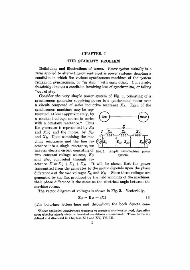
Consider the very simple power system of Fig. 1, consisting of asynchronous generator supplying power to a synchronous motor overa circuit composed of series inductive reactance X&. Each of thesynchronous machines may be rep-resented, at least approximately, bya constant-voltage source in serieswith a constant reactance.* Thusthe generator is represented by Egand XQ) and the motor, by EMand XM- Upon combining the ma-chine reactances and the line re-actance into a single reactance, wehave an electric circuit consisting of pIG< \m Simple two-machine powertwo constant-voltage sources, Eg system,and EM, connected through re-actance X =3 XG + XL + XM . It will be shown that the powertransmitted from the generator to the motor depends upon the phasedifference 8 of the two voltages EG and EM- Since these voltages aregenerated by the flux produced by the field windings of the machines,their phase difference is the same as the electrical angle between themachine rotors.
The vector diagram of voltages is shown in Fig. 2. Vectorially,
EG = EM + jXI [1]
(The bold-face letters here and throughout the book denote com-
*Either equivalent synchronous reactance or transient reactance is used, dependingupon whether steady-state or transient conditions are assumed. These terms aredefined and discussed in Chapters XII and XV, Vol. III.
1
MotorGen.
EMEMTEGTEG
I XG XL XM
X

2 THE STABILITY PROBLEM
plex, or vector, quantities). Hence the current is
jX
^^f The power output of the generator—and like-^ ^ ^ ^ / wise the power input of the motor, since there
^^-<3]g /Jxl is no resistance in the line—is given by
\^~~7/ P = R^(E(?I) [3]
• ^ -Be(l05^) [4]FIG. 2. Vector diagram \ J /
of the system of Fig. 1. w h e r e R e m e a n g ^ ^ p a r t Q f , a n d g ^
means the conjugate of EQ. Now let
EM = EM[0 [5]and
EG = Eold [6]Then _
EG = Eotzl PISubstitution of eqs. 5, 6, and 7 into eq. 4 gives
EG/±- EM/0
-EGEM™Z m
xThis equation shows that the power P transmitted from the generatorto the motor varies with the sine of the displacement angle 6 betweenthe two rotors, as plotted in Fig. 3. The curve is known as a power"angle curve. The maximum power that can be transmitted in thesteady state with the given reactance X and the given internal voltagesEG and EM is
_ EGEM m
"~ X
* £
EM
90*I Ea — E M
jXEG-
(E(?I)
^/90°
EQEM
X- 9 0 ° - 5-90°
'EG2
X u
EQI - 6 -
TLQ — "EM
JXI =
means the conjugate of E(?. Now let
FIG. 2. Vector diagram \ J /of the system of Fig. 1. w h e r e R e m e a n g a^ ^ p a r t Q f , a n d g ^
P = Re
= Re
EQEM
Xcos (-90° - 8)
sin 5
Pm$GEM

DEFINITIONS AND ILLUSTRATIONS OF TERMS 3
and occurs at a displacement angle 8 = 90°. The value of maximumpower may be increased by raising either of the internal voltages or bydecreasing the circuit reactance.
The system is stable only if the displacement angle 8 is in the rangefrom —90° to +90°, in which the slope dP/d8 is positive; that is, therange in which an increase in displacement angle results in an increasein transmitted power. Suppose that the system is operating in thesteady state at point A, Fig. 3. The mechanical input of the generatorand the mechanical output of the motor, if corrected for rotationallosses, will be equal to the electric power P. Now suppose that a
FIG. 3. Power-angle curve of the system of Fig. 1.
small increment of shaft load is added to the motor. Momentarily theangular position of the motor with respect to the generator, and there-fore the power input to the motor, is unchanged; but the motor outputhas been increased. There is, therefore, a net torque on the motortending to retard it, and its speed decreases temporarily. As a resultof the decrease in motor speed, 5 is increased, and consequently thepower input is increased, until finally the input and output are again inequilibrium, and steady operation ensues at a new point B, higher thanA on the power-angle curve. (It has been tacitly assumed that thegenerator speed would remain constant. Actually the generator mayhave to slow down somewhat in order for the governor of its primemover to operate and increase the generator input sufficiently tobalance the increased output.)
P c
B
>APm
180* -90* 3 90° 180°

4 THE STABILITY PROBLEM
Suppose that the motor input is increased gradually until the pointC of maximum power is reached. If now an additional increment ofload is put on the motor, the displacement angle 8 will increase asbefore, but as it does so there will be no increase in input. Insteadthere will be a decrease in input, further increasing the difference be-tween output and input, and retarding the motor more rapidly. Themotor will pull out of step and will probably stall (unless it is keptgoing by induction-motor action resulting from damper circuits whichmay be present). Pm is the steady-state stability limit of the system.It is the maximum power that can be transmitted, and synchronismwill be lost if an attempt is made to transmit more power than thislimit.
If a large increment of load on the motor is added suddenly, insteadof gradually, the motor may fall out of step even though the new loaddoes not exceed the steady-state stability limit. The reason is asfollows: When the large increment of load is added to the motor shaft,the mechanical power output of the motor greatly exceeds the electricalpower input, and the deficiency of input is supplied by decrease ofkinetic energy. The motor slows down, and an increase of the dis-placement angle 8 and a consequent increase of input result. In ac-cordance with the assumption that the new load does not exceed thesteady-state stability limit, 8 increases to the proper value for steady-state operation, a value such that the motor input equals the outputand the retarding torque vanishes. When this value of 8 is reached,however, the motor is running too slowly. Its angular momentumprevents its speed from suddenly increasing to the normal value.Hence it continues to run too slowly, and the displacement angle in-creases beyond the proper value. After the angle has passed thisvalue, the motor input exceeds the output, and the net torque is nowan accelerating torque. The speed of the motor increases and ap-proaches normal speed. Before normal speed is regained, however,the displacement angle may have increased to such an extent that theoperating point on the power-angle curve (Fig. 3) not only goes overthe hump (point C) but also goes so far over it that the motor inputdecreases to a value less than the output. If this happens, the nettorque changes from an accelerating torque to a retarding torque.The speed, which is still below normal, now decreases again, and con-tinues to decrease during all but a small part of each slip cycle. Syn-chronism is definitely lost. In other words, the system is unstable.
If, however, the sudden increment in load is not too great, the motorwill regain its normal speed before the displacement angle becomes toogreat. Then the net torque is still an accelerating torque and causes

DEFINITIONS AND ILLUSTRATIONS OF TERMS 5
the motor speed to continue to increase and thus to become greaterthan normal. The displacement angle then decreases and again ap-proaches its proper value. Again it overshoots this value on accountof inertia. The rotor of the motor thus oscillates about the newsteady-state angular position. The oscillations finally die out be-cause of damping torques, t which have been neglected in this ele-mentary analysis. A damped oscillatory motion characterizes astable system.
With a given sudden increment in load, there is a definite upperlimit to the load which the motor will carry without pulling out of step.This is the transient stability limit of the system for the given condi-tions. The transient stability limit is always below the steady-statestability limit, $ but, unlike the latter, it may have many differentvalues, depending upon the nature and magnitude of the disturbance.The disturbance may be a sudden increase in load, as just discussed, orit may be a sudden increase in reactance of the circuit, caused, forexample, by the disconnection of one of two or more parallel lines as anormal switching operation. The most severe type of disturbance towhich a power system is subjected, however, is a short circuit. There-fore, the effect of short circuits (or "faults," as they are often called)must be determined in nearly all stability studies.
A three-phase short circuit on the line connecting the generator andthe motor entirely cuts off the flow of power between the machines.The generator output becomes zero in the pure-reactance circuits underconsideration; the motor input also becomes zero. Because of theslowness of action of the governor of the prime mover driving thegenerator, the mechanical power input of the generator remains con-stant for perhaps f sec. Also, since the power and torque of the loadon the motor are functions of speed, and since the speed cannot changeinstantly and changes by not more than a few per cent unless and untilsynchronism is lost, the mechanical power output of the motor may beassumed constant. As the electrical power of both machines is de-creased by the short circuit, while the mechanical power of both re-mains constant, there is an accelerating torque on the generator and aretarding torque on the motor. Consequently, the generator speedsup, the motor slows down, and it is apparent that synchronism will belost unless the short circuit is quickly removed so as to restore syn-chronizing power between the machines before they have drifted too
fDiscussed in Chapter XIV, Vol. III.{Conventional methods of calculation, however, sometimes indicate that the
transient stability limit is above the steady-state stability limit. This paradox isdiscussed in Chapter XV, Vol. III.

6 THE STABILITY PROBLEM
far apart in angle and in speed. If the short circuit is on one of twoparallel lines and is not at either end of the line, or if the short circuit isof another type than three-phase—that is, one-line-to-ground, line-to-line, or two-line-to-ground—then some synchronizing power can stillbe transmitted past the fault, but the amplitude of the power-anglecurve is reduced in comparison with that of the pre-fault condition. Insome cases the system will be stable even with a sustained short cir-cuit, whereas in others the system will be stable only if the short cir-cuit is cleared with sufficient rapidity. Whether the system is stableduring faults will depend not only on the system itself, but also on thetype of fault, location of fault, rapidity of clearing, and method ofclearing—that is, whether cleared by the sequential opening of two ormore breakers, or by simultaneous opening—and whether or not thefaulted line is redosed. For any constant set of these conditions, thequestion of whether the system is stable depends upon how much powerit was carrying before the occurrence of the fault. Thus, for anyspecified disturbance, there is a value of transmitted power, called thetransient stability limit, below which the system is stable and abovewhich it is unstable.
The stability limit is one kind of power limit, but the power limit of asystem is not always determined by the question of stability. Evenin a system consisting of a synchronous generator supplying power to aresistance load, there is a maximum power received by the load as theresistance of the load is varied. Clearly there is a power limit herewith no question of stability.
Multimachine systems. Few, if any, actual power systems consistof merely one generator and one synchronous motor. Most powersystems have many generating stations, each with several generators,and many loads, most of which are combinations of synchronousmotors, synchronous condensers, induction motors, lamps, heatingdevices, and others. The stability problem on such a power systemusually concerns the transmission of power from one group of syn-chronous machines to another. As a rule, both groups consist pre-dominantly of generators. During disturbances the machines of eachgroup swing more or less together; that is, they retain approximatelytheir relative angular positions, although these vary greatly withrespect to the machines of the other group. For purposes of analysisthe machines of each group can be replaced by one equivalent machine.If this is done, there is one equivalent generator and one equivalent syn-chronous motor) even though the latter often represents machines thatare actually generators.
Because of uncertainty as to which machines will swing together, or

A MECHANICAL ANALOGUE OF SYSTEM STABILITY 7
in order to improve the accuracy of prediction, it is often desirable torepresent the synchronous machines of a power system by more thantwo equivalent machines. Nevertheless, qualitatively the behavior ofthe machines of an actual system is usually like that of a two-machinesystem. If synchronism is lost, the machines of each group stay to-gether, although they go out of step with the other group.
Because the behavior of a two-machine system represents the be-havior of a multimachine system, at least qualitatively, and becausethe two-machine system is very simple in comparison with the multi-machine system which it represents, the two-machine system is ex-tremely useful in describing the general concepts of power-systemstability and the influence of various factors upon stability. Ac-cordingly, the two-machine system plays a prominent role in this book.
A mechanical analogue of system stability.5§ A simple mechanicalmodel of the vector diagram of Fig. 2 may be built of two pivoted rigidarms representing the Eg and EMvectors, joined at their extremitiesby a spring representing the XI vec-tor. (See Fig. 4.) Lengths rep-resent voltages in the model, justas they do in the vector diagram.The lengths of the arms, EQ andEM, are fixed in accordance with the _ , . ,
, . e , , . , •. FIG. 4. A mechanical analogue of theassumption of constant internal system of Fig lvoltages. The length of the springXI is proportional to the applied tensile force (for simplicity, weassume an ideal spring which returns to zero length if the force isremoved). Hence the tensile force can be considered to represent thecurrent, and the compliance of the spring (its elongation per unit force),to represent the reactance.
The torque exerted on an arm by the spring is equal to the product ofthe length of the arm, the tensile force of the spring, and the sine of theangle between the arm and the spring. (More torque is exerted by thespring when it is perpendicular to the arm than at any other angle forthe same tensile force.) Obviously, the torques on the two arms areequal and opposite. The torque, multiplied by the speed of rotation,gives the mechanical power transmitted from one arm to the other.For convenience of inspection, the mechanical model will be regardedas stationary, rather than as rotating at synchronous speed, just as weregard the usual vector diagram as stationary. The formula for torque(or power) in the model is analogous to that for power in the vector
§Superior numerals refer to items in the list of References at end of chapter.
t(£8
EM-

8 THE STABILITY PROBLEM
diagram, namely: voltage X current X cosine of angle between them.(Since the XI vector is 90° ahead of the / vector, the cosine of theangle between E and / is equal to the sine of the angle between E andXI.)
The shaft power of the machines may be represented by applyingadditional torques to the arms. A convenient method of applying
Synchronouscondenser
GeneratorMotor
-Weights-
-Pan-
FIG. 5. A mechanical analogue of FIG. 6. A mechanical analogue of a three-the system of Fig. 1, suitable for machine system consisting of generator,representing transient conditions. synchronous condenser, and synchronous
motor.
constant equal and opposite torques to the two arms is to attach a drumto each arm and to suspend a weight pan from a pulley hanging on acord, one end of which is wound on each drum, all as indicated inFig. 5.
As weights are added to the pan in small increments, the two arms ofthe model gradually move farther apart until the angle 8 between themreaches 90°, at which position the spring exerts maximum torque. Iffurther weights are added, the arms fly apart and continue to rotate inopposite directions until all the cord is unwound from the drums. Thesystem is unstable. The steady-state power limit is reached at8 = 90°. Although from 90° to 180° the spring force (current) con-tinues to increase, the angle between arm and spring changes in such away that the torque decreases.
The effect of changing the machine voltages can be shown by at-taching the spring to clamps which slide along the arms.
The effect of an intermediate synchronous-condenser station in in-
Spring
•Arms
-Axle-
Drums.
-Table
•Cord-
Pullev

BAD EFFECTS OF INSTABILITY
creasing the steady-state power limit can be shown by adding a thirdpivoted arm attached to an intermediate point of the spring (Fig. 6).The condenser maintains a fixed internal voltage. Since the condenserhas no shaft input or output, no drum is provided on the third arm inthe model. With the intermediate arm (representing the condenser)in place, the angle between the two outer arms (representing thegenerator and motor) may exceed 90° without instability, and thepower limit is greater than before.
The model can be used to illustrate transient stability by providingeach arm with a flywheel such that the combined moment of inertia ofthe arm and flywheel is proportional to that of the corresponding syn-chronous machine together with its prime mover (or load). Thedrums can be made to serve this purpose.
If not too great an increment of load is sud-denly added to the pan, it will be found thatthe arms oscillate before settling down to theirnew steady-state positions. The angle betweenthe arms may exceed 90° during these oscilla-tions without loss of stability. If the incrementof load is too large, the arms will fly apart andcontinue to rotate in opposite directions, indi-cating instability. This may happen eventhough the total load is less than the steady-state stability limit.
The effect of switching out one of two parallellines may be simulated by connecting the armsby two springs in parallel and then suddenlydisconnecting one spring by burning the piece FlG- 7. A mechanicalof string by which the spring is attached. analogue of the effect of a
mv & > c r ii. J.U i- u I1116 fault o n th e powerThe effect of a fault on the line may be simu- system of Fi l
lated by suddenly pushing a point on the springtoward the axle (Fig. 7). The arms will start to move apart, and sta-bility will be lost unless the spring is quickly released.
Models of this kind have been built to give a scale representation ofactual power systems of three or four machines, and the oscillationsof the arms have been recorded by moving-picture cameras.6 Thereare practical difficulties, however, in applying the model representationto a complicated system. The chief value of the model is to illustratethe elementary concepts of stability. Other methods of analysis areused in practice.
Bad effects of instability. When one machine falls out of step withthe others in a system, it no longer serves its function. If it is a
9
10 THE STABILITY PROBLEM
generator, it no longer constitutes a reliable source of electric power.If it is a motor, it no longer delivers mechanical power at the properspeed, if at all. If it is a condenser, it no longer maintains propervoltage at its terminals. An unstable two-machine system, consistingof motor and generator, may be compared to a slipping belt or clutchin a mechanical transmission system; instability means the failure ofthe system as a power-transmitting link.
Moreover, a large synchronous machine out of step is not only use-less; it is worse than useless—it is injurious—because it has a disturb-ing effect on voltages. Voltages will fluctuate up and down betweenwide limits. Thus instability has the same bad effect on service tocustomers' loads as does a fault, except that the effect of instability islikely to last longer. If instability occurs as a consequence of a fault,clearing of the fault itself may not restore stability. The disturbingvoltage fluctuations then continue after the fault has been cleared.The machine, or group of machines, which is out of step with the restof the system must either be brought back into step or else discon-nected from the rest of the system. Either operation, if done manu-ally, may take a long time compared with the time required to clear afault automatically. As a rule, the best way to bring the machinesback into step is to disconnect them and then re-synchronize them.Protective relays have been developed to open a breaker at a pre-determined location when out-of-step conditions occur. Such relays,however, are not yet in wide use. Preferably the power system shouldbe split up into such parts that each part will have adequate generatingcapacity connected to it to supply the load of that part. Some over-load may have to be carried temporarily until the system is re-syn-chronized.
Ordinary protective relays are likely to operate falsely during out-of-step conditions, thereby tripping the circuit breakers of unfaultedlines. Such false tripping may unnecessarily interrupt service totapped loads and may split the system apart at such points that thegenerating capacity of some parts is inadequate. ||
The trend in power-system design has been toward increasing thereliability of electric power service. Since instability has a bad effecton the quality of service, a power system should be designed andoperated so that instability is improbable and will occur only rarely.
Scope of this book. This book will deal with two different phases ofthe problem of power-system stability: (1) methods of analysis andcalculation to determine whether a given system is stable when sub-jected to a specified disturbance; (2) an examination of the effect of
||This aspect of relay operation is discussed fully in Chapter X, Vol. II.

HISTORICAL REVIEW 11
various factors on stability, and a consideration of measures for im-proving stability. In our discussion these two phases will be related:after a method of analysis is presented, it will be applied to show theeffect of varying different factors. Among these factors are systemlayout, circuit impedances, loading of machines and circuits, type offault, fault location, method of clearing, speed of clearing, inertia ofmachines, kind of excitation systems used with the machines, machinereactances, neutral grounding impedance, and damper windings onmachines.
Since transient power limits are lower than steady-state powerlimits, and since any power system will be subject to various shocks,the most severe of which are short circuits, the subject of transientstability is much more important than steady-state stability. Ac-cordingly, the greater part of this book is devoted to transient stability.Chapter XV, Vol. Ill , deals with steady-state stability.
Historical review. Since stability is a problem associated with theparallel operation of synchronous machines, it might be suspected thatthe problem appeared when synchronous machines were first operatedin parallel. The first serious problem of parallel operation, however,was not stability, but hunting. When the necessity for parallel opera-tion of a-c. generators became general, most of the generators weredriven by direct-connected steam engines. The pulsating torquedelivered by those engines gave rise to hunting, which was sometimesaggravated by resonance between the period of pulsation of prime-mover torque and the electromechanical period of the power system.In some cases improper design or functioning of the engine governorsalso aggravated the hunting. Hunting of synchronous motors andconverters was sometimes due to another cause, namely, too high aresistance in the supply line.
The seriousness of hunting was decreased by the introduction of thedamper winding, invented by LeBlanc in France and by Lamme inAmerica. Later, the problem largely disappeared on account of thegeneral use of steam turbines, which have no torque pulsations.Nearly all the prime movers in use nowadays, both steam turbines andwater wheels, give a steady torque. A few generators are still drivenby steam engines or by internal combustion engines. These, as wellas synchronous motors driving compressors, have a tendency to hunt,but, on the whole, hunting is no longer a serious difficulty.
In the first ten or twenty years of this century, stability was not yet asignificant problem. Before automatic voltage-controlling devices(generator-voltage regulators, induction feeder-voltage regulators,synchronous condensers, and the like) had been developed, the power

12 THE STABILITY PROBLEM
systems had to be designed to have good inherent voltage regulation.This requirement called for low reactance in circuits and machines.As a consequence of the low reactances, the stability limits (bothsteady-state and transient) were well above the normally transmittedpower.
The development of automatic voltage regulators made it possibleto increase generator reactances in order to obtain a more economicaldesign and to limit short-circuit currents. By use of induction regu-lators to control feeder voltages, transmission lines of higher impedancebecame practicable. These factors, together with the increased use ofgenerator and bus reactors to decrease short-circuit currents, led to adecrease in the inherent stability of metropolitan power systems.
Stability first became an important problem, however, in connectionwith long-distance transmission, which is usually associated withremote hydroelectric stations feeding into metropolitan load centers. 1fThe application of the automatic generator-voltage regulator to syn-chronous condensers made it possible to get good local voltage regula-tion from a hydroelectric station and a transmission line of high re-actance—and hence of low synchronizing power. The high investmentin these long-distance projects made it desirable to transmit as muchpower as possible over a given line, and there was a temptation totransmit normal power approaching the steady-state stability limit.In a few cases instability occurred during steady-state operation, andmore frequently it occurred because of short circuits. The stabilityproblem is still more acute in connection with long-distance transmis-sion from a generating station to a load center than it is in connectionwith metropolitan systems. It should not be inferred, however, thatmetropolitan systems have no stability problems.
Another type of long-distance transmission which has frequentlyinvolved a stability problem is the interconnection between two largepower systems for the purpose of exchanging power to obtain economiesin generation or to provide reserve capacity. In many cases the con-necting ties were designed to transmit an amount of power which wassmall in comparison with the generating capacity of either system.Consequently, the synchronizing power which the line could transmitwas not enough to retain stability if a severe fault occurred on eithersystem. There was also considerable danger of steady-state pull-outif the power on the tie line was not controlled carefully.
From about 1920 the problem of power-system stability was theobject of thorough investigation. Tests were made both on laboratory
fAmong such hydroelectric stations are Big Creek, Bucks Creek, Pit River,Fifteen Mile Falls, Conowingo, and Boulder Dam.

HISTORICAL REVIEW 13
set-ups and on actual power systems, methods of analyses were de-veloped and checked by tests, and measures for improving stabilitywere developed. Some of the important steps in analytical develop-ment were the following:
1. Circle diagrams for showing the steady-state performance oftransmission systems. These diagrams consist of a family of circles,each of which is the locus of the vector power for fixed voltages atboth sending and receiving ends of the line. The circles are drawnon rectangular coordinates, the abscissas and ordinates of which are,respectively, active and reactive power at either end of the line.These diagrams show clearly the maximum power which a line willcarry in the steady state for given terminal voltages, as well as therelation between the power transmitted and the angular displace-ment between the voltages at the two ends of the line. (Suchdiagrams are described in Chapter XV, Vol. III.)
2. Improvements in synchronous-machine theory, especially theextension of two-reaction theory to the transient performance ofboth salient-pole and nonsalient-pole machines. A number of newreactances were defined and used. (See Chapter XII, Vol. III.)More recently, the effect of saturation on these reactances has beeninvestigated. (See Chapters XII and XV, Vol. III.)
3. The method of symmetrical components for calculating theeffect of unsymmetrical short circuits. (See Chapter VI.) In thisconnection, methods of determining the sequence constants of ap-paratus by test and by calculation had to be devised.
4. Point-by-point methods of solving differential equations, particu-larly the swing equation (giving angular position of a machineversus time). (See Chapter II.)
5. The equal-area criterion for stability of two-machine systems,obviating the more laborious calculation of swing curves for suchsystems. (See Chapter IV.)
6. The a-c. calculating board or network analyzer for the solutionof complicated a-c. networks. (See Chapter III.)
The methods of analysis and calculation now in use are believed to besufficiently accurate for determining whether any given power systemin a given operating condition will be stable when subjected to a givendisturbance. The calculations, however, are rather laborious whenapplied to a large number of different operating conditions of a com-plicated power system.
Methods of analysis will be taken up in the following chapters.Calculated results have been checked in a number of instances by

14 THE STABILITY PROBLEM
observations on actual power systems recorded with automatic oscil-lograph equipment.
REFERENCES
1. R. D. BOOTH and G. C. DAHL, "Power System Stability—a Non-mathe-matical Review," Gen. Elec. Rev., vol. 33, pp. 677-81, December, 1930; and vol. 34,pp. 131-41, February, 1931.
2. A.I.E.E. Subcommittee on Interconnection and Stability Factors, "FirstReport of Power-System Stability," Elec. Eng., vol. 56, pp. 261-82, February, 1937.
3. O. G. C. DAHL, Electric Power Circuits, vol. II, Power-System Stability, NewYork, McGraw-Hill Book Co., 1938.
4. Electrical Transmission and Distribution Reference Book, by Central StationEngineers of the Westinghouse Electric & Manufacturing Company, East Pitts-burgh, Pa., 1st edition, 1942.
a. Chapter 8, "Power System Stability—Basic Elements of Theory and Ap-plication," by R. D. EVANS.
b. Chapter 9, "System Stability—Examples of Calculation," by H. N.MULLER, JR.5. S. B. GRISCOM, "A Mechanical Analogy of the Problem of Transmission
Stability," Elec. Jour., vol. 23, pp. 230-5, May, 1926.6. R. C. BERGVALL and P. H. ROBINSON, "Quantitative Mechanical Analysis of
Power System Transient Disturbances," A.I.E.E. Trans., vol. 47, pp. 915-25,July, 1928; disc, pp. 925-8. Use of mechanical model with seven arms for in-vestigating transient stability of Conowingo transmission system.
PROBLEMS ON CHAPTER I
1. Two synchronous machines of equal rating, having internal voltages(voltages behind transient reactance) of 1.2 and 1.0 per unit, respectively,and transient reactances of 0.25 per unit each, are connected by a line having0.50 per unit reactance and negligible resistance. Assume that the angle5 between the two machines varies from 0 to 360° by 15° steps, and calculatefor each step the current, the power, and the voltage at each of three points:at each end of the line and at its midpoint. Draw loci of the current andvoltage vectors, marking the values of 5 thereon. Also plot in rectangularcoordinates current, power, and voltage, all as functions of 8.
2. Draw the power-angle curve and discuss the condition for stability oftwo machines connected through series capacitive reactance which exceedsthe internal inductive reactance of both machines.