the superalloys fundamentals and applications
DESCRIPTION
Roger C. ReedTRANSCRIPT

7/18/2019 The Superalloys Fundamentals and Applications
http://slidepdf.com/reader/full/the-superalloys-fundamentals-and-applications 1/389

7/18/2019 The Superalloys Fundamentals and Applications
http://slidepdf.com/reader/full/the-superalloys-fundamentals-and-applications 2/389
This page intentionally left blank

7/18/2019 The Superalloys Fundamentals and Applications
http://slidepdf.com/reader/full/the-superalloys-fundamentals-and-applications 3/389
The Superalloys
Superalloys are unique high temperature materials used in gas turbine engines, which dis-
play excellent resistance to mechanical and chemical degradation. This book presents theunderlying metallurgical principles which have guided their development and practical as-
pects of component design and fabrication from an engineering standpoint. The topics of
alloy design, process development, component engineering, lifetime estimation and mate-
rials behaviour are described, with emphasis on critical components such as turbine blades
and discs.
The first introductory text on this class of materials, it will provide a strong grounding
for those studying physical metallurgy at the advanced level, as well as practising engineers.
Included at the end of each chapter are exercises designed to test the reader’s understanding
of the underlying principles presented. Additional resources for this title are available at
www.cambridge.org/9780521859042.
r o g e r c . r e e d is Professor and Chair in Materials Science and Engineering at Imperial
College London. From 1994 to 2002, he was Assistant Director of Research in the Rolls-
Royce University Technology Centre at the University of Cambridge. From 2002 to 2005, he
held a Canada Research Chair in the Department of Materials Engineering at the University
of British Columbia, Vancouver. He is widely known in the gas turbine community for his
work on the physical metallurgy of the superalloys, and has taught extensively in this field.

7/18/2019 The Superalloys Fundamentals and Applications
http://slidepdf.com/reader/full/the-superalloys-fundamentals-and-applications 4/389

7/18/2019 The Superalloys Fundamentals and Applications
http://slidepdf.com/reader/full/the-superalloys-fundamentals-and-applications 5/389
The Superalloys
Fundamentals and ApplicationsRoger C. Reed

7/18/2019 The Superalloys Fundamentals and Applications
http://slidepdf.com/reader/full/the-superalloys-fundamentals-and-applications 6/389
cambridge university pressCambridge, New York, Melbourne, Madrid, Cape Town, Singapore, São Paulo
Cambridge University PressThe Edinburgh Building, Cambridge cb2 2ru, UK
First published in print format
isbn-13 978-0-521-85904-2
isbn-13 978-0-511-24546-6
© R. C. Reed 2006
2006
Information on this title: www.cambridge.org/9780521859042
This publication is in copyright. Subject to statutory exception and to the provision of relevant collective licensing agreements, no reproduction of any part may take place without the written permission of Cambridge University Press.
isbn-10 0-511-24546-7
isbn-10 0-521-85904-2
Cambridge University Press has no responsibility for the persistence or accuracy of urlsfor external or third-party internet websites referred to in this publication, and does notguarantee that any content on such websites is, or will remain, accurate or appropriate.
Published in the United States of America by Cambridge University Press, New York
www.cambridge.org
hardback
eBook (EBL)
eBook (EBL)
hardback
7/18/2019 The Superalloys Fundamentals and Applications
http://slidepdf.com/reader/full/the-superalloys-fundamentals-and-applications 7/389
But if I were to say, my fellow citizens, that we shall send a rocket to the moon, 240 000
miles away from the control station in Houston, a giant rocket more than three hundred feet
tall, the length of this football field, made of new metal alloys, some of which have not yet
been invented, capable of standing heat and stresses several times more than have ever been
experienced, fitted together with a precision better than the finest watch, carrying all the
equipment needed for propulsion, guidance, control, communications, food and survival,
on an untried mission, to an unknown celestial body, and then return it safely to Earth,
re-entering the atmosphere at speeds of over 25 000 miles per hour, causing heat about half
that of the temperature of the sun, almost as hot as it is here today, and do all this, and do it
right, and do it first before this decade is out, then we must be bold . . .
From John F. Kennedy’s speech at Rice University, Houston, Texas, 12 September 1962

7/18/2019 The Superalloys Fundamentals and Applications
http://slidepdf.com/reader/full/the-superalloys-fundamentals-and-applications 8/389

7/18/2019 The Superalloys Fundamentals and Applications
http://slidepdf.com/reader/full/the-superalloys-fundamentals-and-applications 9/389
Contents
Foreword by Dr Mike Hicks Page xi
Preface xiii
Acknowledgements xv
1 Introduction 1
1.1 Background: materials for high-temperature applications 11.1.1 Characteristics of high-temperature materials 11.1.2 The superalloys as high-temperature materials 21.1.3 Instances of superalloy component failures 5
1.2 The requirement: the gas turbine engine 8
1.3 The selection of materials for high-temperature applications 14
1.3.1 Larson–Miller approach for the ranking of creep performance 141.3.2 Historical development of the superalloys 181.3.3 Nickel as a high-temperature material: justification 25
1.4 Summary 28
Questions 29
References 31
2 The physical metallurgy of nickel and its alloys 33
2.1 Composition–microstructure relationships in nickel alloys 342.1.1 The FCC phase 352.1.2 The gamma prime phase 402.1.3 Other phases in the superalloys 49
2.2 Defects in nickel and its alloys 552.2.1 Defects in the gamma (FCC) phase 552.2.2 Defects in the gamma prime phase 65
2.3 Strengthening effects in nickel alloys 732.3.1 Strengthening by particles of the gamma prime phase 74
2.3.2 Temperature dependence of strengthening in the superalloys 812.3.3 The anomalous yielding effect in gamma prime alloys 86
2.4 The creep behaviour of nickel alloys 902.4.1 The creep behaviour of nickel 912.4.2 Creep strengthening in nickel alloys by solid-solution strengthening 952.4.3 Creep strengthening in nickel alloys by precipitation hardening 99
vii

7/18/2019 The Superalloys Fundamentals and Applications
http://slidepdf.com/reader/full/the-superalloys-fundamentals-and-applications 10/389
viii Contents
2.5 Summary 101
Appendix. The anisotropic elasticity displayed by nickel 103
Questions 108
References 114
3 Single-crystal superalloys for blade applications 121
3.1 Processing of turbine blading by solidification processing 1223.1.1 The practice of investment casting: directional solidification 1223.1.2 Analysis of heat transfer during directional solidification 1303.1.3 Formation of defects during directional solidification 1393.1.4 The influence of processing conditions on the scale of the
dendritic structure 143
3.2 Optimisation of the chemistry of single-crystal superalloys 1473.2.1 Guideline 1 1523.2.2 Guideline 2 1543.2.3 Guideline 3 1573.2.4 Guideline 4 162
3.3 Mechanical behaviour of the single-crystal superalloys 1703.3.1 Performance in creep 1713.3.2 Performance in fatigue 187
3.4 Turbine blading: design of its size and shape 1943.4.1 Estimation of the length of the turbine aerofoils 1963.4.2 Choice of mean radius for turbine blading 1983.4.3 Estimation of exit angle from blade cross-section 200
Appendix. Growth of an isolated dendrite, using hemispherical
needle approximation 202
Questions 203
References 211
4 Superalloys for turbine disc applications 217
4.1 Processing of the turbine disc alloys 2174.1.1 Processing by the cast and wrought route 2224.1.2 Processing by the powder route 231
4.2 Composition, microstructure and properties of turbine disc alloys 2364.2.1 Guideline 1 2384.2.2 Guideline 2 2464.2.3 Guideline 3 252
4.3 Service life estimation for turbine disc applications 2594.3.1 Stress analysis of a turbine disc of simplified geometry 2594.3.2 Methods for lifing a turbine disc 2604.3.3 Non-destructive evaluation of turbine discs 271
Questions 274
References 278

7/18/2019 The Superalloys Fundamentals and Applications
http://slidepdf.com/reader/full/the-superalloys-fundamentals-and-applications 11/389
Contents ix
5 Environmental degradation: the role of coatings 283
5.1 Processes for the deposition of coatings on the superalloys 2855.1.1 Electron beam physical vapour deposition 2855.1.2 Plasma spraying 288
5.1.3 Pack cementation and chemical vapour deposition methods 2935.2 Thermal barrier coatings 297
5.2.1 Quantification of the insulating effect 2975.2.2 The choice of ceramic material for a TBC 2985.2.3 Factors controlling the thermal conductivity of a ceramic coating 301
5.3 Overlay coatings 3055.3.1 Oxidation behaviour of Ni-based overlay coatings 3075.3.2 Mechanical properties of superalloys coated with overlay coatings 312
5.4 Diffusion coatings 317
5.5 Failure mechanisms in thermal barrier coating systems 3245.5.1 Introduction 3245.5.2 Observations of failure mechanisms in TBC systems 3255.5.3 Lifetime estimation models 3315.5.4 The role of imperfections near the TGO 333
5.6 Summary 335
Questions 337
References 340
6 Summary and future trends 351
6.1 Trends in superalloys for turbine blade applications 353
6.2 Trends in superalloys and processes for turbine disc applications 357
6.3 Concluding remarks 361
References 362
Index 363

7/18/2019 The Superalloys Fundamentals and Applications
http://slidepdf.com/reader/full/the-superalloys-fundamentals-and-applications 12/389

7/18/2019 The Superalloys Fundamentals and Applications
http://slidepdf.com/reader/full/the-superalloys-fundamentals-and-applications 13/389
Foreword
I am grateful to Cambridge University Press for allowing me to make some comments
about Roger Reed’s new textbook The Superalloys: Fundamentals and Applications.
Nickel-based superalloys represent a very important class of engineering material, findingwidespread application for example in critical components within the gas turbine engines
used for jet propulsion and electricity generation. This is due to their superior mechanical
properties that are maintained to elevated temperatures. Indeed, new classes of superal-
loy are continually being sought by gas turbine manufacturers around for the world for
applications in the hottest parts of the engine. This is because higher temperatures result
in improvements to the efficiency of the engine and therefore lower fuel burn. Engine
performance is a major factor in any power plant competition, which helps to explain
why all the engine manufacturers spend so much money developing future generations of
superalloys.The author has provided us with a textbook covering both the fundamentals and appli-
cations of superalloy technology. This is a significant and unique achievement, especially
given the broad range of subject matter dealt with. In Chapter 1, the requirement for mate-
rials capable of operating at elevated temperatures is introduced along with the historical
development of the nickel-based superalloys and their emergence as materials for high-
temperature applications. Chapter 2 concerns the physical metallurgy of the superalloys,
with an emphasis on the details which distinguish them from other classes of engineering
alloys, for example the gamma prime strengthening phase, the role of defects such as the
anti-phase boundary, the unique particle-strengthening mechanisms, the anomalous yield
effect and the creep deformation behaviour. Chapters 3 and 4 deal with superalloy tech-
nology as applied to two major gas turbine components of critical importance: the turbine
blade and discs. Of note is the balanced coverage given to the processing, alloy design and
microstructure/property relationships relevant to superalloys used for these distinct applica-
tions. Chapter 5 deals with surface coatings technologies, which are becoming increasingly
critical as operating temperatures continue to rise. In Chapter 6, projections are made about
the future of superalloy technology.
In view of the author’s exemplary treatment of the subject, this tectbook deserves to become the definitive textbook in the field for the foreseeable future. I have found myself
referring to it on many occasions already! It is recommended to all those with an interest
in the field of high-temperature materials, particularly those involved with gas turbine
technology or those embarking on a higher degree in the subject. Also, since the superalloys
xi

7/18/2019 The Superalloys Fundamentals and Applications
http://slidepdf.com/reader/full/the-superalloys-fundamentals-and-applications 14/389
xii Foreword
represent a considerable success story in the field of materials science and engineering, it
is recommended for use within the materials-related curricula at universities.
Dr Mike Hicks
Chief Technologist – Materials
Rolls-Royce plc

7/18/2019 The Superalloys Fundamentals and Applications
http://slidepdf.com/reader/full/the-superalloys-fundamentals-and-applications 15/389
Preface
Based upon nickel, but containing significant amounts of at least ten other elements in-
cluding chromium and aluminium, the superalloys are high-temperature materials which
display excellent resistance to mechanical and chemical degradation at temperatures closeto their melting points. Since they first emerged in the 1950s, these alloys have had a unique
impact. Consider the aeroengines which power the modern civil aircraft. The superalloys
are employed in the very hottest sections of the turbines, under the heaviest of loads, with
the utmost importance placed on assuring the integrity of the components fabricated from
them. Indeed, the development of the superalloys has been intrinsically linked to the his-
tory of the jet engine for which they were designed; quite simply, a modern jet aeroplane
could not fly without them. Further improvements in temperature capability are now being
actively sought, for example for the engines to power the two-decked Airbus A380 and
the Boeing 787 Dreamliner. Superalloys are being employed increasingly in the land-based turbine systems used for generating electricity, since fuel economy is improved and carbon
emissions are reduced by the higher operating conditions so afforded. But new develop-
ments in superalloy metallurgy are required for the next generation of ultra-efficient power
generation systems. Over the next 25 years, the world’s installed power generation capacity
is expected to double, due to the rapidly growing economies and populations of the de-
veloping countries, and because most of the current plant in the developed countries will
need to be replaced. Thus the superalloys have never been more important to the world’s
prosperity.
The remarkable performance of today’s superalloys is not merely fortuitous. Numerous
researchers and technologists have worked to develop the basic understanding of their
physical behaviour and the more practical aspects required to put these alloys to best use.
With this book, the reader is presented with an introduction to the metallurgical principles
which have guided their development. It turns out that the topics of alloy design, process
development, component engineering, lifetime estimation and materials behaviour are very
closely inter-related. The book is aimed at those pursuing degrees in Materials Science and
Engineering, but those studying Mechanical Engineering, Aerospace Engineering, Physics
and Chemistry will also find it useful. It has been developed with two audiences in mind: first,final-year undergraduate students taking an elective course in high-temperature materials
technology, and, secondly, students embarking on a higher degree in this field who seek
an introduction to the subject. Included at the end of the first five chapters are questions
designed to test the reader. Many of these require numerical working using a calculator,
spreadsheet or computer programming tool. Most of these exercises have been tested on
xiii

7/18/2019 The Superalloys Fundamentals and Applications
http://slidepdf.com/reader/full/the-superalloys-fundamentals-and-applications 16/389
xiv Preface
students at Imperial College, the University of Cambridge and the University of British
Columbia, where I have held teaching positions. I would like to receive comments from
those who have attempted the problems – I will attempt to answer all queries as promptly
as I can. My email address can be found at www.cambridge.org/9780521859042.
In preparing the book, the reader should be aware that it has been necessary to be
selective about the content included in it. I have included sufficient material to satisfy the
requirements of a one-course semester – about 30 hour-long periods, some of which should
be used for classwork, problem sets and design exercises. In my own teaching I have used the
book’s contents to emphasise the relationships between the structure/composition of these
materials, their mechanical/chemical behaviour, the processing of them and the design of the
components which have provided the technological impetus for their development. Thus, a
proper balance between these different topics has been sought; the need for this makes the
superalloys an excellent case study in the field of materials.

7/18/2019 The Superalloys Fundamentals and Applications
http://slidepdf.com/reader/full/the-superalloys-fundamentals-and-applications 17/389
Acknowledgements
It is a great pleasure to acknowledge the considerable number of friends and colleagues
who have generously provided information during the writing of this book. The following
deserve special mention: Dr Cathie Rae, Dr Sammy Tin, Dr David Knowles, Professor Harry Bhadeshia of the University of Cambridge; Professor Malcolm McLean, Dr Barbara
Shollock, Professor Peter Lee and Dr David Dye of Imperial College, London; Professor
John Knott of the University of Birmingham; Dr Nirundorn Matan of Walaikak University;
Dr Philippa Reed of the University of Southampton; Professor Tresa Pollock of the Uni-
versity of Michigan; Professor Alan Ardell of UCLA; Professor Kevin Hemker of Johns
Hopkins University; Professor Hael Mughrabi of the University of Erlangen; Professor
Brian Gleeson of Iowa State University; Professor Mike Mills of The Ohio State Univer-
sity; Dr Vladimir Tolpygo of the University of California at Santa Barbara; Professor Alec
Mitchell, Dr Steve Cockcroft and Dr Ainul Akhtar from the University of British Columbia;Dr Mike Winstone of DSTL Laboratories, Farnborough, UK; Dr Hiroshi Harada, Dr Hiro
Hono, Dr Seiji Kuroda, Dr Hongbo Guo and Mr Atsushi Sato of the National Institute
for Materials Science, Japan; Dr Bruce Pint, Dr Suresh Babu and Dr Mike Miller of Oak
Ridge National Laboratory, USA; Dr Jim Smialek and Dr Tim Gabb of NASA; Dr Pierre
Caron from ONERA, France; Dr Jeff Brooks of Qinetiq, UK; and Dr Dan Miracle of the
Wright-Patterson Air Force Laboratory, USA. I would like to thank Dr Bob Broomfield of
Rolls-Royce plc, who was particularly helpful during the period 1994 to 2002 whilst I was
working at the University of Cambridge. Neil Jones, Jim Wickerson, Dr Andrew Manning,
Dr Henri Winand, Colin Small, Dr Duncan MacLachlan, Paul Spilling, Dr Steve Mckenzie,
Steve Williams and Dr Ken Green of Rolls-Royce also provided information very gra-
ciously. More recently, very helpful advice has been received from Dr Scott Walston of GE
Aircraft Engines, Dr Ken Harris and Dr Jackie Wahl of Cannon-Muskegon Corporation,
Dr Allister James of Siemens Westinghouse, and Dr Gern Maurer and Dr Tony Banik of
Special Metals Corporation. Last but not least, thanks to Joanna Copeman of University
College London for her love and support.
xv

7/18/2019 The Superalloys Fundamentals and Applications
http://slidepdf.com/reader/full/the-superalloys-fundamentals-and-applications 18/389

7/18/2019 The Superalloys Fundamentals and Applications
http://slidepdf.com/reader/full/the-superalloys-fundamentals-and-applications 19/389
1 Introduction
1.1 Background: materials for high-temperature applications
1.1.1 Characteristics of high-temperature materialsCertain classes of material possess a remarkable ability to maintain their properties at el-
evated temperatures. These are the high-temperature materials. Their uses are many and
varied, but good examples include the components for turbines, rockets and heat exchang-
ers. For these applications, the performance characteristics are limited by the operating
conditions which can be tolerated by the materials used. For example, the thrust and
fuel economy displayed by the modern aeroengine is strongly dependent upon, and lim-
ited by, the high-temperature strength of the nickel-based superalloys used for its hottest
sections.What are the desirable characteristics of a high-temperature material? The first is an
ability to withstand loading at an operating temperature close to its melting point . If the
operating temperature is denoted T oper and the melting point T m, a criterion based upon
the homologous temperature τ defined as T oper /T m is sensible; this should be greater than
about 0.6. Thus, a superalloy operating at 1000◦C in the vicinity of the melting temperature
of nickel, 1455◦C, working at a τ of (1000+ 273)/(1455+ 273) ∼ 0.75, is classified as
a high-temperature material. But so is ice moving in a glacier field at −10 ◦C, since τ is
263/273 ∼ 0.96, although its temperature is substantially lower. A second characteristic
is a substantial resistance to mechanical degradation over extended periods of time. For high-temperature applications, a time-dependent, inelastic and irrecoverable deformation
known as creep must be considered – due to the promotion of thermally activated processes
at high τ . Thus, as time increases, creep strain, creep, is accumulated; for most applications,
materials with low rates of creep accumulation, creep, are desirable. In common with other
structural materials, the static properties of yield stress, ultimate tensile strength and fracture
toughness are also important – and these must be maintained over time. A final characteristic
is tolerance of severe operating environments. For example, the hot gases generated in a
coal-fired electricity-generating turbine are highly corrosive due to the high sulphur levels
in the charge. Kerosene used for aeroengine fuel tends to be cleaner, but corrosion due to
impurities such as potassium salts and the ingestion of sea-water can occur during operation.
In these cases, the high operating temperatures enhance the possibility of oxidation. Under
such conditions, any surface degradation reduces component life.
1

7/18/2019 The Superalloys Fundamentals and Applications
http://slidepdf.com/reader/full/the-superalloys-fundamentals-and-applications 20/389
2 Introduction
Fig. 1.1. Artist’s impression of the turbomachinery in Rolls-Royce’s Trent 800 engine, which
powers the Boeing 777 aircraft. (Courtesy of Rolls-Royce.)
1.1.2 The superalloys as high-temperature materials
When significant resistance to loading under static, fatigue and creep conditions is re-
quired, the nickel-base superalloys [1–3] have emerged as the materials of choice for high-
temperature applications. This is particularly true when operating temperatures are beyond
about 800 ◦C. This is the case for gas turbines used for jet propulsion, for example, the
100 000 lb thrust engines used for the Rolls-Royce Trent 800 and General Electric GE90
which power the Boeing 777 [4] (see Figure 1.1), but also the smaller 1000 lb engines used
for helicopter applications. Gas turbines are used also for electricity generation, for example,
the 250 MW gas-fired industrial plant which can generate enough power to satisfy a large
city of a million people (see Figure 1.2), or the smaller 3 MW gas-fired generators suitable
for back-up facilities [5]. When weight is a consideration, titanium alloys are used, but
their very poor oxidation resistance restricts their application to temperatures below about
700 ◦C [6]. For some electricity-generating power plant applications which rely upon super-
heated steam at 565 ◦C, high-strength creep-resistant ferritic steels are preferred on account
of their lower cost. However, the latest generation of ultra-supercritical steam-generating
coal-fired power stations requires boiler tubing that can last up to 200 000 hours at 750◦C
and 100 MPa – new types of superalloy are being developed for these applications [7], since
ferritic steels cannot be designed to meet these property requirements. Generally speaking,
ceramics such as silicon carbide and nitride are not used for these applications, despitetheir excellent oxidation and creep resistance, due to their poor toughness and ductility.
Zirconia-based ceramics do, however, find applications in thermal barrier coatings which
are used in association with the superalloys for high-temperature applications.
Since the technological development of the superalloys is linked inextricably to the gas
turbine engine, it is instructive to consider the functions of its various components [8].

7/18/2019 The Superalloys Fundamentals and Applications
http://slidepdf.com/reader/full/the-superalloys-fundamentals-and-applications 21/389
1.1 Materials for high-temperature applications 3
Fig. 1.2. Artist’s impression of the turbomachinery in Siemens Westinghouse’s W501F gas turbine
engine, used for electricity generation. (Courtesy of Siemens Westinghouse.)
Fig. 1.3. Diagram illustrating the basic features of a very basic gas turbine engine: the turbojet.
(Courtesy of Rolls-Royce.)
Consider the turbojet engine, Figure 1.3. The role of the compressor , consisting of com-
pressor blades and discs, is to squeeze the incoming air, thus increasing its pressure. The
compressed air enters the combustor , where it is mixed with fuel and ignited. The hot gases
are allowed to expand through a turbine, which extracts the mechanical work required to
drive the compressor; this necessitates a shaft , which transmits the torque required for this
to happen. In the case of the turbojet, thrust arises from the momentum change associated with the incoming air being accelerated and its emergence as exhaust gas at a significantly
higher velocity. Variants of this basic design are possible. In a turbofan engine, an additional
low-pressure compressor, or fan, is added to the front of the engine. Although this necessi-
tates an additional shaft and an associated turbine to drive it, the weight penalty associated
with the extra turbomachinery is offset by the greater fuel economy – this arises from the

7/18/2019 The Superalloys Fundamentals and Applications
http://slidepdf.com/reader/full/the-superalloys-fundamentals-and-applications 22/389
4 Introduction
CompositeAluminium
Titanium
Steel
Nickel
Kevlar
Fig. 1.4. Illustration of material usage in the Trent 800 engine. Note the extensive use of
nickel-based superalloys in the combustor and turbine sections (see the back cover for a colour
version of this figure). (Courtesy of Rolls-Royce.)
thrust provided from the air, which bypasses the turbines. Figure 1.4 illustrates the different
materials used in the various parts of the Trent 800 aeroengine. One sees that titanium alloys
are chosen for the fan and compressor sections, on account of their low density, good spe-
cific strength and fatigue resistance. However, in the combustor and turbine arrangements,
the nickel-based superalloys are used almost exclusively. Superalloys are used also in the
final (high-pressure) stages of the compressor.
When designing a gas turbine engine, great emphasis is placed on the choice of the
turbine entry temperature (TET): the temperature of the hot gases entering the turbine
arrangement [9]. There, the temperature falls as mechanical work is extracted from the gas
stream; therefore the conditions at turbine entry can be considered to be the most demanding
on the turbomachinery and the nickel-based superalloys from which are they made. As will
be seen in Section 1.2, the performance of the engine is greatly improved if the TET can
be raised – and over the 50 years since their conception, this has provided the incentive
and technological impetus to enhance the temperature capability of the superalloys, and to
improve their processing and the design of components fabricated from them. The success of
these enterprises can be judged from the way in which the TET of the large civil aeroengine
has increased since Whittle’s first engine of 1940 (Figure 1.5); a 700◦C improvementin a 60-year period has been achieved [10]. Of course, the TET varies greatly during a
typical flight cycle (see Figure 1.6), being largest during the take-off and climb to cruising
altitude. Turbines for power-generating applications experience fewer start-up/power-down
cycles but very much longer periods of operation, during which the TET tends to be rather
constant.

7/18/2019 The Superalloys Fundamentals and Applications
http://slidepdf.com/reader/full/the-superalloys-fundamentals-and-applications 23/389
1.1 Materials for high-temperature applications 5
2300Uncooled
turbineblades
Cooledturbineblades Thermal
barrier
coatingsEngine TET
Material capability
2200
2100
2000
1900
1800
1700
1600
1500
1400
1300
1200
1100
1000 W1Derwent
DartAvon
Conway
Spey
RB211-22C
RB211-524-02
RB211-524-B4RB211-535-B4
RB211-524-G
Trent 700, 800Trent 500, 900
wrought alloys
conventionally cast alloysDS cast alloys
SC castalloys
9001940 1950 1960 1970 1980
Year
T a k e - o f f T E T ( K )
1990 2000 2010
Fig. 1.5. Evolution of the turbine entry temperature (TET) capability of Rolls-Royce’s civil
aeroengines, from 1940 to the present day. Adapted from ref. [10].
Take-off
ClimbCruise
Reverse thrust
Approach
Flight idle Ground idleGround idle
0 2 23 86
Time (min)
E
n g i n e r a t i n g o r T E T
102 107108
Fig. 1.6. Variation of the turbine entry temperature (TET) during a typical flight cycle of a civil
aircraft.
1.1.3 Instances of superalloy component failures
The failure of components fabricated from the superalloys is a rare occurrence, since the
applications demand very conservative designs and significant safety factors. Nevertheless,
failures have occurred and undoubtedly there will be further ones in the future. Examination
of some examples emphasises a number of important points.

7/18/2019 The Superalloys Fundamentals and Applications
http://slidepdf.com/reader/full/the-superalloys-fundamentals-and-applications 24/389
6 Introduction
Fig. 1.7. Images of the General Electric CFM56 turbofan engine, which failed in service in October
2000, shortly after taking off from Hobart, Australia [11]. (a) General view of the high-pressure
turbine; (b) high-pressure turbine rotor with the failed blade indicated; (c) failed high-pressure
turbine blade; (d) tip notch damage observed on the remaining blades.
Consider first the case of a Boeing 737 powered by two General Electric CFM56 turbofan
engines, which, on 13 October 2000, experienced an in-flight engine failure that resulted in
the engine being shut down and the aircraft returning safely to Hobart airport in Tasmania,
Australia [11]. After disassembly and inspection of the engine, failure was attributed to
the loss of a 15 mm by 20 mm segment from the trailing edge of a single high-pressure
(HP) turbine blade (see Figure 1.7) fabricated from the Rene 125 alloy. This passed into
the low-pressure turbine stages, where it caused overloading and collapse of the entire blade
array. Metallographic examination of the HP blades indicated that radial cracks near the
blade tips were common, as a result of severe thermal cycling, high thermal gradients and thermal fatigue. Many of the tips had been weld-repaired using the Rene 80 alloy. In the
failed blade, tip cracks had grown into a v-shaped notch because of oxidation and corro-
sion effects, and had intercepted a deep underlying repair weld fabricated from the lower
strength superalloy Inconel 625. On reaching the base of the repair weld, the resultant fatigue
stresses were sufficient to propagate the cracking to the point of final failure. The failed

7/18/2019 The Superalloys Fundamentals and Applications
http://slidepdf.com/reader/full/the-superalloys-fundamentals-and-applications 25/389
1.1 Materials for high-temperature applications 7
Fig. 1.8. Schematic diagram of the arrangement of the combustor in the Pratt & Whitney JT8D-15
engine [12].
blade had completed 17 928 flight cycles, and had flown 5332 cycles since its repair and
overhaul.
A second example had very much more tragic consequences. On 22 August 1985, at
Manchester Airport in the United Kingdom, a British Airways Boeing 737 carrying 131
passengers and 6 crew suffered an uncontained engine failure during take-off, which was
therefore aborted by the crew [12]. Unfortunately, pieces from the port Pratt & Whitney
JT8D-15 engine were ejected from the engine – and these punctured a fuel tank causing
a catastrophic fire, in which 55 persons on board lost their lives. The aeroplane had not
left the ground. The origin of the failure was a 360◦ separation of the No 9 combustor can
(see Figure 1.8), which consisted of 11 pieces of the superalloy Hastelloy X in sheet form,
welded together; this allowed hot gases to escape from it and impinge upon the inner surface
of the combustion chamber outer case, which ruptured catastropically during take-off due
to localised overheating, see Figure 1.9. In November 1983, after 3371 cycles, the No 9
can had been inspected and circumferential cracking of 180 mm combined length had been
repaired, by fusion welding. Solutioning and weld stress-relief heat treatments had not been
applied. It lasted a further 2036 cycles before failure.
In these instances, lessons should be learned from these tragic circumstances. The fol-lowing should be clear to the reader. First, the modern jet engine relies very heavily upon the
superalloys to withstand the significant loads and temperatures developed during operation.
Secondly, where defects exist due to manufacturing or else due to damage accumulated
during service, these can lead to catastrophic failure; hence, for these applications it is ab-
solutely critical to ensure the components fabricated from the superalloys are of the highest

7/18/2019 The Superalloys Fundamentals and Applications
http://slidepdf.com/reader/full/the-superalloys-fundamentals-and-applications 26/389
8 Introduction
Fig. 1.9. View of failed combustor in the failed Pratt & Whitney JT8D-15 engine, August 1985,
Manchester Airport, UK [12].
integrity and quality. Thirdly, procedures for inspection and repair are critical if ongoingoperation is to remain safe. Finally, a close integration of procedures for component de-
sign, manufacturing and lifetime estimation is required in order to ensure the safe working
conditions of components fabricated from the superalloys, and gas turbines in general.
1.2 The requirement: the gas turbine engine
The gas turbine used for jet propulsion and electricity generation is an example of a heatengine. The power output therefore depends upon the temperature increment through which
the working fluid is raised – it is improved if this can be increased.
In order to reinforce this concept, consider Carnot’s reversible heat engine, which consists
of an ideal gas that cycles between hot and cold reservoirs of temperatures T 1 and T 2,
respectively; see Figure 1.10(a). Once each cycle, an amount of heat, QAB, is absorbed
from the hot reservoir and a quantity, QCD, is transferred to the cold one; a fraction, η, of
the heat, QAB, absorbed from the hot reservoir is converted into useful work,W ,suchthatthe
efficiency, η, equals W /QAB with conservation of energy requiring that W = QAB − QCD.
It is relatively easy to determine expressions for η and W . Writing the ideal gas equationas pV = n RT , where p is pressure, V is volume, T is temperature, R is the gas constant
and n is the number of moles, one must consider the following four steps [13].
(1) The gas, in perfect thermal contact with the hot reservoir, undergoes an infinitely slow
expansion from volume V A to V B. During this process, the work done by the gas, W AB,

7/18/2019 The Superalloys Fundamentals and Applications
http://slidepdf.com/reader/full/the-superalloys-fundamentals-and-applications 27/389
1.2 The gas turbine engine 9
(a)
(b) (c)
T 1
T 1
T 2
T 2
BA
CB
DC
AD
P r e s s u r e
A
B
D
C
Volume
A
D
B
C T e m p e r a t u r e
Entropy
Fig. 1.10. The Carnot cycle for an ideal gas. (a) The four steps of the cycle: two isothermal and two
adiabatic. (b) Corresponding pressure–volume diagram. (c) The associated temperature–entropy
diagram. Adapted from ref. [13].
is given by
W AB =
V B
V A
p d V =
V B
V A
n RT 1
V d V = n RT 1 ln
V B
V A
= QAB (1.1)
(2) A second step, in which thermal contact to the reservoir is broken and the gas is insulated
from its surroundings: the gas undergoes an adiabatic expansion from state B to state
C along the adiabat BC, such that pBV γ
B = pCV γ
C , where γ is the ratio of specific heats
at constant pressure and volume. Since the gas is isolated, QBC = 0. The work done by
the gas, W BC, is given by
W BC =
V C
V B
p d V =
V C
V B
pBV γ
B
V γ d V =
pCV C − pBV B
1 − γ =
n R(T 1 − T 2)
γ − 1(1.2)
where T 1 and T 2 are the initial and final temperatures, respectively.(3) A third step: the gas, in contact with the cold reservoir at temperature T 2, undergoes
an isothermal compression from V C to V D. Work is done on the gas such that
W CD =
V D
V C
p d V =
V D
V C
n RT 2
V d V = n RT 2 ln
V D
V C
= QCD (1.3)

7/18/2019 The Superalloys Fundamentals and Applications
http://slidepdf.com/reader/full/the-superalloys-fundamentals-and-applications 28/389
10 Introduction
0 0.5 1 1.5 2 0
3
4
9
1
200
300500700900
1100
130015001700
400 600 800
1×10⁶
2×10⁶
3×10⁶
4×10⁶
p ( P a
)
(a) (b)
34
19
V (m3 /kg)
1 3 4 9
Fuel
T ( K
)
S (J/kg K)
Fig. 1.11. Pressure–volume and temperature–entropy diagrams for the turbojet. Adapted from
ref. [10].
(4) In the final step, an adiabatic compression takes the gas from state D to its initial state
A. Appealing to the result of step 2, the work done on the gas is given by
W DA =n R(T 2 − T 1)
γ − 1(1.4)
Since the gas is isolated, QDA = 0. Note that W DA = −W BC.
The total work, W , obtained in the cycle is given by
W = W AB + W BC + W CD + W DA = QAB + QCD = n RT 1 ln
V B
V A
− n RT 2 ln
V C
V D
(1.5)
and is equal to the area enclosed by the loop ABCD in Figure 1.10(b); this follows from
a consideration of the four integrals,
p d V , defining W . The efficiency, η, defined as the
ratio of the useful work obtained, W , to the heat absorbed from the heat source, QAB, is
given by
η =W
QAB
= 1 −T 2 ln{V C/V D}
T 1 ln{V B/V A}= 1 −
T 2
T 1(1.6)
where use has been made of relationships such as pAV A = pBV B and pBV γ
B = pCV γ
C , etc.
It follows that if T 1 is raised, or T 2 is reduced, the work extracted from the cycle is increased
and the efficiency improved. In practice, raising T 1 is the more practical option – with the
limit for T 1 being the capability of the turbomachinery to withstand the high-temperatures
and stresses involved. Figure 1.10(c) shows the temperature–entropy plot for the reversible
Carnot cycle.
The assumptions made in the Carnot cycle make it only a first approximation for thegas turbine engine, particularly as additions of mass and heat are made to the working
fluid via the burning of fuel. However, the fuel-to-air ratio is typically only 0.02–0.03 at
maximum power and 0.01 under cruise conditions. Therefore, the pressure–volume cycle
for a simple turbojet (see Figure 1.11(a)) exhibits many of the features expected from the
Carnot cycle; note in particular the 40-fold increase in pressure. Figure 1.11(b) shows the
corresponding temperature–entropy plot (the numbers 1, 3, 4 and 9 have been chosen for

7/18/2019 The Superalloys Fundamentals and Applications
http://slidepdf.com/reader/full/the-superalloys-fundamentals-and-applications 29/389
1.2 The gas turbine engine 11
T e m p e r a t u r e
(0,0)
CW
1
3
4
9
TW
UW
Entropy
Highpressure
Lowpressure
Z
Fig. 1.12. Simplified temperature–entropy diagram for the turbojet, with compression and turbine
stages assumed to be isentropic. CW = compression work; TW = turbine work; UW = useful work;
Z = ideal work of combustion.
consistency with commonly used terminology in gas-turbine design). Note that neither the
work of compression nor the work of expansion in the compressor are isentropic, implying
irreversibility, and that the chemical energy introduced in the combustion chamber leads to
a significant increase in temperature of about 800 K. These effects are not accounted for in
the Carnot analysis.
To make approximate but quantitative calculations, one can assume that the compressor
and turbine stages are isentropic, so that the lines 1–3 and 4–9 in Figure 1.11(b) are vertical.
Furthermore, the lines 3–4 and 1–9 can be assumed to be straight but diverging; they must of
course pass through the point (0, 0) since at zero kelvin gases have no entropy. The situation
is then as depicted in Figure 1.12. The distance 1–3 is proportional to the compression work
(CW), and the distance 4–9 is proportional to the sum of the turbine work (TW) and the
useful work (UW): the work of expansion (EW). The vertical distance between 3 and 4
measured along the temperature axis is proportional to Z , the rate of addition of chemicalenergy from the fuel, or the ideal work of combustion. Because the lines 3–4 and 1–9
diverge, and since for an ideal cycle CW = TW, the quantity UW is finite and positive; it
can be used for propulsion or else to drive an external shaft for electricity generation.
Example question
A turbojet is operating with a TET of 1400 K, an overall pressure ratio (OPR) of 25
and an air-mass intake, ˙ M , of 20 kg/s. Assuming an ideal cycle such that the compres-
sion work equals the turbine work, determine the rate of useful working (or specific power) available to provide a propulsive force. Hence estimate the thermal efficiency,
ηth. Assume adiabatic, reversible processes where necessary. As a further exercise, es-
timate (i) the thrust, F N, developed and (ii) the propulsive efficiency, η prop, if the ve-
locity of the intake air is 250 m/s. (Assume c p = 1000 J/(kg K), γ = 1.4 and the intake
air to have a temperature of 288 K and velocity V 0. Take atmospheric pressure to be
101 325 Pa.)

7/18/2019 The Superalloys Fundamentals and Applications
http://slidepdf.com/reader/full/the-superalloys-fundamentals-and-applications 30/389
12 Introduction
T e m p e r a t u r e
Entropy
C B A
(a)
Overall pressure ratio
S p e c i f i c w o r k ,
U W
IncreasingTET
(b)
CB
A
Fig. 1.13. (a) Idealised temperature–entropy diagrams for the turbojet, for large (C), medium (B)and small (A) overall pressure ratios. (b) Plots of specific work vs. OPR for various TETs.
Solution For an adiabatic, reversible process one has
T 3
T 1=
p3
p1
γ −1
γ
and since the pressure ratio p3/ p1 = 25, this yields T 3 = 723 K if T 1 = 288 K. In a sim-
ilar way, T 9 = 558 K if T 4 = 1400 K. Then Z = ˙ Mc p(T 4 − T 3) = 13.6 MW, CW = TW=
˙ Mc p(T 3 − T 1) = 8.7 MW and EW = ˙ Mc p(T 4 − T 9) = 16.8 MW. It follows that the useful
work, UW, is 16.8 − 8.7 = 8.1 MW.
The thermal efficiency is defined as the ratio of useful work to the work of combustion,
i.e.
ηth = UW/Z = 8.1/13.6 = 0.60
These considerations demonstrate that the turbine entry temperature, T 4, needs to be as
high as possible, if the useful work is to be maximised. Since the constant pressure lines
diverge, UW is greatest when T 4 is large. There does, however, need to be a balance betweena high TET and a large enough OPR; see Figure 1.13. This is because at very low or very
high OPRs, the difference between CW and the EW is minimal, and, since CW= TW, then
negligible work is available for propulsion.
The useful work, UW, is spent increasing the kinetic energy of the gas stream passing
through the engine; hence,
UW =1
2˙ M
V 2 jet − V 20
so that V jet = 934 m/s. The thrust, F N, is then given by (from momentum considerations)
F N = ˙ M [V jet − V 0]
or 20× (934− 250) = 13680N.
The propulsive efficiency is a measure of the proportion of jet kinetic energy (relative to
the engine) which is converted to rate of working (by the thrust) on the aeroplane, defined

7/18/2019 The Superalloys Fundamentals and Applications
http://slidepdf.com/reader/full/the-superalloys-fundamentals-and-applications 31/389
1.2 The gas turbine engine 13
6000 7000 8000 9000 10000 11000 12000 13000 14000 15000 16000
Thrust (N)
0.5
0.6
0.7
0.8
0.9
1
1.1
1.2
1.3
S p e c i f i c f u e l c o n s u m p t i o n , Z
/ F N
C
1000 K
1100 K
1200 K1300 K
1400 K1500 K
OPR 6
OPR 8
OPR 12
OPR 16
OPR 20
OPR 24OPR 28
OPR 32
Fig. 1.14. Performance diagram illustrating the variation of the specific fuel consumption (defined
as normalised fuel burn/thrust developed) against thrust, for various values of the TET and OPR.
according to
η prop = F NV 0
˙ M 2
V 2 jet − V 20
This yields a value of 0.42.
Such calculations, although simplistic, can be used to justify the use of the bypass design
for a modern civil aeroengine; see Figure 1.1. Thrust is required for propulsion, and this
depends upon bothηth and η prop.Ahighηth demands large TET and reasonable OPR. Hence,
if the available useful work, UW, is used primarily to accelerate the air passing through the
engine, then it is inevitable that the jet velocity will be very high, and the thrust, F N,
and specific fuel consumption (SFC), too large. This is demonstrated in Figure 1.14. The
propulsive efficiency,η prop, is correspondingly very low. The only way around this dilemma
is to use a bypass design. Most of the useful work developed by the core of the engine is
used to accelerate a much greater mass of air through a fan to a modest exit velocity. The
remaining useful work is used to accelerate the core air to a rather modest V jet.
These considerations explain why a modern civil turbofan aeroengine has a bypass
ratio between 6:1 and perhaps 9:1 – to develop reasonableη prop and SFC. For a military
aeroengine, however, a low bypass ratio of 1.2:1 is more appropriate since a high thrust-to-weight ratio is required; furthermore, the fan diameter must be small to prevent the
engine protruding from the airframe so that speed and acceleration is maximised. For
further reading, refer to ref. [10] for a thorough and lucid introduction to the aerodynamic
design of modern engines for civil and military aircraft. The analysis also explains why
there has been a tremendous drive to increase both the pressure ratio and the turbine entry

7/18/2019 The Superalloys Fundamentals and Applications
http://slidepdf.com/reader/full/the-superalloys-fundamentals-and-applications 32/389
14 Introduction
temperature of large land-based industrial gas turbines, with values at the time of writing of
20 and 1425◦C, respectively, being commonplace; see Table 1.1 [14]. In turn, these more
demanding operating conditions place more stringent requirements on the materials used.
Table 1.2 summarises the alloys and coatings used in the hot sections of the latest generation
of large IGTs [14]. As will become apparent, for IGT applications there is a trend towards
(i) the use of single-crystal superalloys for the blading, with cobalt-based superalloys such
as ECY-768 finding less favour and (ii) the application of coatings technologies for the
provision of environmental protection. These topics are dealt with in detail in Chapters 3
and 5, respectively.
1.3 The selection of materials for high-temperature applications
Materials for high-temperature service must withstand considerable loads for extended
periods of time. What are the best materials to choose for these applications? Can we justify
the use of the superalloys which have nickel as the major constituent?
1.3.1 Larson–Miller approach for the ranking of creep performance
Resistance to creep deformation is a major consideration. For many materials and under
loading conditions which are invariant with time, the creep strain rate, ss, is constant; i.e.
it approaches a steady-state [14]. This implies a balance of creep hardening, for example,
due to dislocation multiplication and interaction with obstacles, and creep softening, for
example, due to dislocation annihilation and recovery. Very often, it is found that
ss = Aσ n exp
−
Q
RT
(1.7)
where σ is the applied stress, n is the stress exponent, A is a constant and Q is an activation
energy. When a value for Q is deduced from the experimental creep data, one often finds that
it correlates with the activation energy for self-diffusion, see Figure 1.15 [15]. This impliesthat some form of mass transport on the scale of the microstructure is rate-controlling.
Design against creep usually necessitates a consideration of thetime to rupture, t r , which
usually satisfies the so-called Monkman–Grant relationship
t r × ss = B (1.8)
where B is a constant which is numerically equal to the creep ductility, i.e. the creep strain
to failure. Then at constant σ one has
t r exp− Q
RT
= C (1.9)
or
log10 t r − 0.4343Q
RT = D (1.10)

7/18/2019 The Superalloys Fundamentals and Applications
http://slidepdf.com/reader/full/the-superalloys-fundamentals-and-applications 33/389
T a b l e 1 . 1 . E v o l u t i
o n o f t h e f e a t u r e s o f l a r g e l a
n d - b a s e d i n d u s t r i a l g a s t u r b i n e s [ 5 ]
Y e a r o f i n t r o d u c t i o n
1 9 6 7
1 9 7 2
1 9 7 9
1 9 9 0 a
1 9 9 8 b
T u r b i n e i n l e t t e m p e
r a t u r e ( ◦ C )
9 0 0
1 0 1 0
1 1 2 0
1 2 6 0
1 4 2 5
P r e s s u r e t a t i o
1 0 . 5
1 1
1 4
1 4 . 5
1 9 – 2 3
E x h a u s t t e m p e r a t u r
e ( ◦ C )
4 2 7
4 8 2
5 3 0
5 8 2
5 9 3
C o o l e d t u r b i n e r o w s
R 1 v a n e
R 1 , R 2 v a n e ,
R 1 , R 2 v a n e ,
R 1 , R 2 , R 3 v a n e ,
R 1 , R 2 , R 3 v a n e ,
R 1 b l a d e
R 1 , R 2 b l a d e
R 1 , R 2 , R 3 b l a d e
R 1 , R 2 , R 3 b l a d e
P o w e r r a t i n g , M W
5 0 – 6 0
6 0 – 8 0
7 0 – 1 0 5
1 6 5 – 2 4 0
1 6 5 – 2 8 0
E f fi c i e n c y , s i m p l e c
y c l e ( % )
2 9
3 1
3 4
3 6
3 9
E f fi c i e n c y , c o m b i n e
d c y c l e ( % )
4 3
4 6
4 9
5 3
5 8
N o t e : a C o r r e s p o n d s a p p r o x i m a t e l y t o G E 7 F , 7 A / 9
F , W e s t i n g h o u s e 5 0 1 F / 7 0 1 F a n
d S i e m e n s V 8 4 . 3 / 9 4 . 3 t u r b i n e s
.
b C o r r e s p o n d s a p p r o x i m a t e l y t o G E 7 H / 9 H , W e s t i n g h o u s e 5 0 1 G / 7 0 1 G , S i e m e n s V 8 4 . 3 A / 9 4 . 3 A a n d A B B G T 2 4 / 2 6 t u r b i n e s .

7/18/2019 The Superalloys Fundamentals and Applications
http://slidepdf.com/reader/full/the-superalloys-fundamentals-and-applications 34/389
T a b l e 1 . 2 . A l l o y s a n d c o a t i n g s u s e d i
n t h e h o t s e c t i o n s o f v a r i o u s
i n d u s t r i a l g a s t u r b i n e s , a s a t t h e e n d o f 1 9 9 7 [ 5 ]
M a n u f a c t u r e r
M o d e l
V a n e s
B l a d e s
C o a
t i n g s
A B B
1 1 N 2
I N 9 3 9
I N
7 3 8 L C
N i C
r A l Y + S i
G T 2 4 / 2 6
D S C M 2 4 7 L C ( R 1 ) /
D S C M 2 4 7 L C ( R 1 – 3 ) /
T B C ( R 1 V ) / N i C r A l Y + S i ( R 2 – 4 B
, V )
M a r M 2 4 7 L C ( R 2 , 3 ) /
M a r M 2 4 7 L C ( R 4 , 5 )
U n c o a t e d R 5 V , C h r o m i s e d ( R 5 B )
I N 7 3 8 ( R 4 , 5 )
G E
7 / 9 E A
F S X - 4 1 4 ( a l l s t a g e s )
G T D - 1 1 1 / I N 7 3 8 /
R T 2 2 / G T 2 9 - I n + ( R 1 B )
U d i m e t 5 0 0
7 / 9 F A
F S X - 4 1 4 ( R 1 ) /
D S G T D - 1 1 1 ( R 1 ) /
G T 3 3 - I n / G T - 2 9 - I n + /
G T D - 2 2 2 ( R 2 , 3 )
G T D - 1 1 1 ( R 2 , 3 )
C h r
o m i s e ( R 3 )
7 H
S C R e n e N 5 ( R 1 ) /
S C
R e n e N 5 ( R 1 ) /
T B C ( R 1 , 2 B , V ) /
F S X - 4 1 4 / G T D - 2 2 2
D S G T D - 1 1 1 ( R 2 , 3 )
A l l
o t h e r s G T 3 3
S i e m e n s
V 8 4 / 9 4 . 2
I N 9 3 9
I N
7 3 8 L C / I N 7 9 2 ( R 4 )
C o N
i C r A l Y + S i
V 8 4 / 9 4 . 3 A
S C P W A 1 4 8 3 ( R 1 , 2 ) /
S C
P W A 1 4 8 3 ( R 1 , 2 )
T B C ( E B - P V D R 1 B ) / M C r A l Y + R
e
I N 9 3 9
W e s t i n g h o u s e /
5 0 1 D 5 / 7 0 1 D
E C Y - 7 6 8 / X - 4 5
U d i m e t 5 2 0
M C
r A l Y
M i t s u b i s h
i
5 0 1 / 7 0 1 F
E C Y - 7 6 8 / X - 4 5
I N
7 3 8 L C
T B C ( R 1 B , V ) /
M C
r A l Y / S e r m a l l o y J
5 0 1 / 7 0 1 G
I N 9 3 9
D S M a r M 0 0 2 ( R 1 , 2 ) /
T B C ( R 1 , 2 B , V ) /
C M 2 4 7
E B - P V D / M C r A l Y
N o t e : R 1 , R 2 , e t c . r e f e r t o t h e fi r s t , s e c o n
d r o t o r s e c t i o n s , e t c . ; B a n d V r e f e r t o b l a d e a n d v a n e , r e s p e c t i v e l y .

7/18/2019 The Superalloys Fundamentals and Applications
http://slidepdf.com/reader/full/the-superalloys-fundamentals-and-applications 35/389
1.3 The selection of materials 17
W
AI2O3Nb
UO2
γ−Fe
Pt
MgO
Au
CuMg
PbZn
α-TI
β-TIIn
Cd
00
100
200
300
400
500
600
700
100 200 300 400 500 600 700
Sn
AI NaCIAgBr
Niδ− Fe
β− Co
α− Fe
Activation energy for high-temperature creep (kJ/mol)
A c t i v a t i o n e n e r g y f o r s e l f - d i f f u s i o n ( k J / m o l )
Fig. 1.15. Correlation between the creep activation energy and the energy for diffusion for several
materials. Data taken from ref. [15].
where C and D are constants. Equation (1.10) can be written in the form
T [ E + log10 t r ] = P (1.11)
where P is known as the Larson–Miller parameter and E is the Larson–Miller constant;
this is found to vary between 15 and 25 log h and is taken to be 20 log h. When creep tests
for various combinations of (σ, T ) are carried out, one usually finds a strong correlation
between P and logσ , consistent with the assumptions made. These plots are known as
Larson–Miller diagrams.
In Figure 1.16, the performance of various materials are compared. Note that the al-
loys SRR99, CMSX-4 and RR3000 are first-, second- and third-generation single-crystal
superalloys, which are used for the turbine blades of modern aeroengines. Waspaloy is a
polycrystalline superalloy used for the turbine discs required to house the blading. MA754
is an oxide-dispersion-strengthened superalloy made by powder metallurgy. Ti-6242 is a
titanium alloy used widely for the compressor sections of modern aeroengines; it has the
highest creep resistance of any of the titanium alloys. Also shown are various intermetallic
compounds such as NiAl, Ni3Al, TiAl, Ti3Al and FeAl, and other exotic alloys such as Nb-I,
Mo-41Re and thoria-doped tungsten; these show promise as high-temperature materials,
but they have not yet found application in the gas turbine. A number of points emergefrom a consideration of Figure 1.16. First, for any given material the Larson–Miller line is
approximately straight, although there is a tendency for some non-linearity, which results
in the lines curving gently downwards. Second, in comparison with the other materials, it is
clear that the single crystal superalloys behave excellently; the shift towards the right as one
moves from SRR99, CMSX-4 to RR3000 has arisen due to the metallurgists who have been

7/18/2019 The Superalloys Fundamentals and Applications
http://slidepdf.com/reader/full/the-superalloys-fundamentals-and-applications 36/389
18 Introduction
15 20 25 3010
20
30
40
50
60708090
100
200
300
400
500
600700800900
1000
35 40 45
Larson–Miller parameter, P = T [20 + log(t )] (×103)
A p p l i e d s t r e s s ( M P a )
Fe3AI
Ti3Al
TiAl
MA754
NiAl
Ni3Al
FeAI
Ti-6242
Waspaloy
ThO2 –W
CMSX-4
SRR99
Nb–I (vacuum)
RR3000
Mo–41Re
Fe3AI + TiB2
Fig. 1.16. Values of the Larson–Miller parameter, P , for a number of high-temperature materials.
The horizontal and near-vertical lines have spacings equivalent to a factor of 2 change in creep life
and 200 ◦C temperature capability, respectively; the materials which display the best
high-temperature performance lie towards the top right of the diagram. Adapted from a graph
provided by Dan Miracle.
able to produce alloys of increasing creep resistance; these improvements turn out to be
very substantial, although clearly if a step change could be made to a new alloy system, for
example, one based upon niobium, then this would be very advantageous. Polycrystalline
superalloys such as Waspaloy are less good in creep, but their behaviour exceeds that of
many other alloy systems. The intermetallic compounds are not bad, particularly if one
makes the comparison on a density-corrected basis; it turns out, however, that their tough-
ness is no match for that displayed by the superalloys. Finally, titanium alloys behave well,
although it has been found that their oxidation resistance beyond about∼700 ◦C is very
poor, and this limits their range of application – it has been found necessary, for example,
to use superalloys for the last stages of the compressor sections of many aeroengines, even
though titanium alloys are used for the first stages. Alternative materials based upon W
or Mo show promise, although their density tends to be significant. Niobium alloys seem
attractive, but their resistance to oxidation is very poor.
1.3.2 Historical development of the superalloys
Over the latter part of the twentieth century, a concerted period of alloy and process devel-
opment enabled the performance of the superalloys to be improved dramatically. Although
further improvements are being actively pursued, it is important to recognise this historical

7/18/2019 The Superalloys Fundamentals and Applications
http://slidepdf.com/reader/full/the-superalloys-fundamentals-and-applications 37/389
1.3 The selection of materials 19
Fig. 1.17. Evolution of the high-temperature capability of the superalloys over a 60 year period
since their emergence in the 1940s.
context, since much can be learned from it. Figure 1.17 provides a perspective for the alloy
and process development which has occurred since the first superalloys began to appear
in the 1940s; the data relate to the materials and processes for turbine blading, so that the
creep performance (here taken as the highest temperature at which rupture occurs in not
less than 1000 h, at 137 MPa) is a suitable measure for the progress which has been made.
Various points emerge from a study of the figure. First, one can see that, for the blad-
ing application, cast rather than wrought materials are now preferred since the very best
creep performance is then conferred. However, the first aerofoils were produced in wrought
form. During this time, alloy development work – which saw the development of the first
Nimonic alloys [1] – enabled the performance of the blading to be improved considerably;
the vacuum induction casting technologies which were introduced in the 1950s helped with
this since the quality and cleanliness of the alloys were improved dramatically. Second,
the introduction of improved casting methods, and later the introduction of processing by
directional solidification, enabled significant improvements to be made; this was due to
the columnar microstructures that were produced in which the transverse grain boundaries
were absent (see Figure 1.18). Once this development occurred, it was quite natural toremove the grain boundaries completely such that monocrystalline (single-crystal) super-
alloys were produced. This allowed, in turn, the removal of grain-boundary strengthening
elements such as boron and carbon which had traditionally been added; this enabled better
heat treatments to reduce microsegregation and eutectic content induced by casting, whilst
avoiding incipient melting during heat treatment. The fatigue life is then improved.

7/18/2019 The Superalloys Fundamentals and Applications
http://slidepdf.com/reader/full/the-superalloys-fundamentals-and-applications 38/389
20 Introduction
Fig. 1.18. Turbine blading in the (a) equiaxed, (b) columnar and (c) single-crystal forms [8].
Nowadays, single-crystal superalloys are being used in increasing quantities in the gas
turbine engine; if the very best creep properties are required, then the turbine engineers
turn to them, although it should be recognised that the use of castings in the columnar
and equiaxed forms is still practised in many instances. It can be shown by the reader that
the data in Figure 1.16 indicate that creep rupture lives of the single-crystal superalloys
have been lengthened from about 250 h at 850◦C/500 MPa for a typical first-generation
alloy such as SRR99, to about 2500 h for the third-generation alloy RR3000. Under more
demanding conditions, for example, 1050◦C/150 MPa, rupture life has improved four-
fold from 250 h to 1000 h. These improvements were won in a period of approximately
15 years between 1980 and 1995, primarily as a consequence of a better appreciation of
the physical factors which confer high-temperature strength in these materials. It should
be appreciated that each of the different engine manufacturers and materials suppliers
have searched for their own proprietary compositions; Table 1.3 lists the compositions of
common cast superalloys, including those used in single-crystal form. One can see that as
many as 14 different alloying additions are added. The so-called first-generation single-
crystal superalloys, such as PWA1480, Rene N4 and SRR99, contain appreciable quantities
of the γ hardening elements Al, Ti and Ta; the grain-boundary-strengthening elements
C and B, which were added routinely to the earlier directionally solidified alloys, are no
longer present. Second-generation alloys, such as PWA1484, CMSX-4 and Rene N5, are
characterised by a 3 wt% concentration of Re, which is increased to about 6 wt% for the
third-generation alloys such as CMSX-10 and Rene N6. Generally speaking, the modern
alloys are characterised by significantly lower concentrations of Cr and higher concentrations
of Al and Re. Concentrations of Ti and Mo are now at very modest levels. The period since2000 has seen the emergence of the fourth-generation single-crystal superalloys, such as
MC-NG, EPM-102 and TMS-162, which are characterised by additions of ruthenium.
Table 1.4 lists the chemical compositions of common wrought superalloys, which are
employed therefore in polycrystalline form. When their compositions are compared with
those of the cast superalloys, various points emerge. The concentrations of theγ hardening

7/18/2019 The Superalloys Fundamentals and Applications
http://slidepdf.com/reader/full/the-superalloys-fundamentals-and-applications 39/389
T a b l e 1 . 3 . T h e c o m p o s i t i o n s ( i n w e i g h t % ) o f s
o m e c o m m o n c a s t s u p e r a l l o y s
A l l o y
C
r
C o
M o
W
A l
T i
T a
N b
R e
R u
H f
C
B
Z
r
N i
A M 1
7 . 0
8 . 0
2 . 0
5 . 0
5 . 0
1 . 8
8 . 0
1 . 0
—
—
—
—
—
—
B a l
A M 3
8 . 0
5 . 5
2 . 2 5
5 . 0
6 . 0
2 . 0
3 . 5
—
—
—
—
—
—
—
B a l
C M 1 8 6 L C
6 . 0
9 . 3
0 . 5
8 . 4
5 . 7
0 . 7
3 . 4
—
3 . 0
—
1 . 4
0 . 0 7
0 . 0 1 5
0 . 0 0 5
B a l
C M 2 4 7 L C
8 . 0
9 . 3
0 . 5
9 . 5
5 . 6
0 . 7
3 . 2
—
—
—
1 . 4
0 . 0 7
0 . 0 1 5
0 . 0 1 0
B a l
C M S X - 2
8 . 0
5 . 0
0 . 6
8 . 0
5 . 6
1 . 0
6 . 0
—
—
—
—
—
—
—
B a l
C M S X - 3
8 . 0
4 . 8
0 . 6
8 . 0
5 . 6
1 . 0
6 . 3
—
—
—
0 . 1
—
—
—
B a l
C M S X - 4
6 . 5
9 . 6
0 . 6
6 . 4
5 . 6
1 . 0
6 . 5
—
3 . 0
—
0 . 1
—
—
—
B a l
C M S X - 6
1
0 . 0
5 . 0
3 . 0
—
4 . 8
4 . 7
6 . 0
—
—
—
0 . 1
—
—
—
B a l
C M S X - 1 0
2 . 0
3 . 0
0 . 4
5 . 0
5 . 7
0 . 2
8 . 0
—
6 . 0
—
0 . 0 3
—
—
—
B a l
E P M - 1 0 2
2 . 0
1 6 . 5
2 . 0
6 . 0
5 . 5 5
—
8 . 2 5
—
5 . 9 5
3 . 0
0 . 1 5
0 . 0 3
—
—
B a l
G T D - 1 1 1
1
4 . 0
9 . 5
1 . 5
3 . 8
3 . 0
5 . 0
3 . 1 5
0 . 0 7
—
—
—
0 . 1 0
0 . 0 1 4
0 . 0 0 7
B a l
G T D - 2 2 2
2
2 . 5
1 9 . 1
—
2 . 0
1 . 2
2 . 3
0 . 9 4
0 . 8
—
—
—
0 . 0 8
0 . 0 0 4
0 . 0 2
B a l
I N 1 0 0
1
0 . 0
1 5 . 0
3 . 0
—
5 . 5
4 . 7
—
—
—
—
—
0 . 1 8
0 . 0 1 4
0 . 0 6
B a l
I N - 7 1 3 L C
1
2 . 0
—
4 . 5
—
5 . 9
0 . 6
—
2 . 0
—
—
—
0 . 0 5
0 . 0 1
0 . 1 0
B a l
I N - 7 3 8 L C
1
6 . 0
8 . 5
1 . 7 5
2 . 6
3 . 4
3 . 4
1 . 7 5
0 . 9
—
—
—
0 . 1 1
0 . 0 1
0 . 0 4
B a l
I N - 7 9 2
1
2 . 4
9 . 2
1 . 9
3 . 9
3 . 5
3 . 9
4 . 2
—
—
—
—
0 . 0 7
0 . 0 1 6
0 . 0 1 8
B a l
I N - 9 3 9
2
2 . 4
1 9 . 0
—
2 . 0
1 . 9
3 . 7
—
1 . 0
—
—
—
0 . 1 5
0 . 0 0 9
0 . 1 0
B a l
M a r - M 0 0 2
8 . 0
1 0 . 0
—
1 0 . 0
5 . 5
1 . 5
2 . 6
—
—
—
1 . 5
0 . 1 5
0 . 0 1 5
0 . 0 3
B a l
M a r - M 2 4 6
9 . 0
1 0 . 0
2 . 5
1 0 . 0
5 . 5
1 . 5
1 . 5
—
—
—
1 . 5
0 . 1 5
0 . 0 1 5
0 . 0 5
B a l
M a r - M 2 4 7
8 . 0
1 0 . 0
0 . 6
1 0 . 0
5 . 5
1 . 0
3 . 0
—
—
—
1 . 5
0 . 1 5
0 . 0 1 5
0 . 0 3
B a l
M a r - M 2 0 0 H f
8 . 0
9 . 0
—
1 2 . 0
5 . 0
1 . 9
—
1 . 0
—
—
2 . 0
0 . 1 3
0 . 0 1 5
0 . 0 3
B a l
M a r - M 4 2 1
1
5 . 0
1 0 . 8
1 . 8
3 . 3
4 . 5
1 . 6
—
2 . 3
—
—
—
0 . 1 8
0 . 0 1 9
0 . 0 4
B a l
M C 2
8 . 0
5 . 0
2 . 0
8 . 0
5 . 0
1 . 5
6 . 0
—
—
—
0 . 1
—
—
—
B a l
M C - N G
4 . 0
—
1 . 0
5 . 0
6 . 0
0 . 5
5 . 0
—
4 . 0
4 . 0
0 . 1
—
—
—
B a l
M X 4
2 . 0
1 6 . 5
2 . 0
6 . 0
5 . 5 5
—
8 . 2 5
—
5 . 9 5
3 . 0
0 . 1 5
0 . 0 3
—
—
B a l

7/18/2019 The Superalloys Fundamentals and Applications
http://slidepdf.com/reader/full/the-superalloys-fundamentals-and-applications 40/389
T a b l e 1 . 3 . ( c o n t . )
A l l o y
C r
C o
M o
W
A l
T i
T a
N b
R e
R u
H f
C
B
Z r
N i
N a s a i r 1 0 0
9 . 0
—
1 . 0
1 0 . 5
5 . 7 5
1 . 2
3 . 3
—
—
—
—
—
—
—
B a l
P W A 1 4 2 2
9 . 0
1 0 . 0
—
1 2 . 0
5 . 0
2 . 0
—
1 . 0
—
—
1 . 5
0 . 1 4
0 . 0 1 5
0 . 1
B a l
P W A 1 4 2 6
6 . 5
1 0 . 0
1 . 7
6 . 5
6 . 0
—
4 . 0
—
3 . 0
—
1 . 5
0 . 1 0
0 . 0 1 5
0 . 1
B a l
P W A 1 4 8 0
1 0 . 0
5 . 0
—
4 . 0
5 . 0
1 . 5
1 2 . 0
—
—
—
—
—
—
—
B a l
P W A 1 4 8 3
1 2 . 2
9 . 2
1 . 9
3 . 8
3 . 6
4 . 2
5 . 0
—
—
—
—
0 . 0 7
—
—
B a l
P W A 1 4 8 4
5 . 0
1 0 . 0
2 . 0
6 . 0
5 . 6
—
9 . 0
—
3 . 0
—
0 . 1
—
—
—
B a l
P W A 1 4 8 7
5 . 0
1 0 . 0
1 . 9
5 . 9
5 . 6
—
8 . 4
—
3 . 0
—
0 . 2 5
—
—
—
B a l
P W A 1 4 9 7
2 . 0
1 6 . 5
2 . 0
6 . 0
5 . 5 5
—
8 . 2 5
—
5 . 9 5
3 . 0
0 . 1 5
0 . 0 3
—
—
B a l
R e n e 8 0
1 4 . 0
9 . 0
4 . 0
4 . 0
3 . 0
4 . 7
—
—
—
—
0 . 8
0 . 1 6
0 . 0 1 5
0 . 0 1
B a l
R e n e 1 2 5
9 . 0
1 0 . 0
2 . 0
7 . 0
1 . 4
2 . 5
3 . 8
—
—
—
0 . 0 5
0 . 1 1
0 . 0 1 7
0 . 0 5
B a l
R e n e 1 4 2
6 . 8
1 2 . 0
1 . 5
4 . 9
6 . 1 5
—
6 . 3 5
—
2 . 8
—
1 . 5
0 . 1 2
0 . 0 1 5
0 . 0 2
B a l
R e n e 2 2 0
1 8 . 0
1 2 . 0
3 . 0
—
0 . 5
1 . 0
3 . 0
5 . 0
—
—
—
0 . 0 2
0 . 0 1 0
—
B a l
R e n e N 4
9 . 0
8 . 0
2 . 0
6 . 0
3 . 7
4 . 2
4 . 0
0 . 5
—
—
—
—
—
—
B a l
R e n e N 5
7 . 0
8 . 0
2 . 0
5 . 0
6 . 2
—
7 . 0
—
3 . 0
—
0 . 2
—
—
—
B a l
R e n e N 6
4 . 2
1 2 . 5
1 . 4
6 . 0
5 . 7 5
—
7 . 2
—
5 . 4
—
0 . 1 5
0 . 0 5
0 . 0 0 4
—
B a l
R R 2 0 0 0
1 0 . 0
1 5 . 0
3 . 0
—
5 . 5
4 . 0
—
—
—
—
—
—
—
—
B a l
S R R 9 9
8 . 0
5 . 0
—
1 0 . 0
5 . 5
2 . 2
1 2 . 0
—
—
—
—
—
—
—
B a l
T M S - 7 5
3 . 0
1 2 . 0
2 . 0
6 . 0
6 . 0
—
6 . 0
—
5 . 0
—
0 . 1
—
—
—
B a l
T M S - 1 3 8
2 . 9
5 . 9
2 . 9
5 . 9
5 . 9
—
5 . 6
—
4 . 9
2 . 0
0 . 1
—
—
—
B a l
T M S - 1 6 2
2 . 9
5 . 8
3 . 9
5 . 8
5 . 8
—
5 . 6
—
4 . 9
6 . 0
0 . 0 9
—
—
—
B a l

7/18/2019 The Superalloys Fundamentals and Applications
http://slidepdf.com/reader/full/the-superalloys-fundamentals-and-applications 41/389
T a b l e 1 . 4 . T h e c o m p o s i t i o n s ( i n w e i g h t % ) o f s
o m e c o m m o n w r o u g h t s u p e r a l l o y s
A l l o y
C r
C o
M o
W
N b
A l
T i
T a
F e
H
f
C
B
Z r
N i
A l l o y 1 0
1 1 . 5
1 5
2 . 3
5 . 9
1 . 7
3 . 8
3 . 9
0 . 7 5
—
—
0 . 0 3 0
0 . 0 2 0
0 . 0 5
B a l
A s t r o l o y
1 5 . 0
1 7 . 0
5 . 3
—
—
4 . 0
3 . 5
—
—
—
0 . 0 6
0 . 0 3 0
—
B a l
C - 2 6 3
1 6
1 5
3
1 . 2 5
—
2 . 5 0
5 . 0
—
—
—
0 . 0 2 5
0 . 0 1 8
—
B a l
H a s t e l l o y S
1 5 . 5
—
1 4 . 5
—
—
0 . 3
—
—
1 . 0
—
—
0 . 0 0 9
—
B a l
H a s t e l l o y X
2 2 . 0
1 . 5
9 . 0
0 . 6
—
0 . 2 5
—
—
1 8 . 5
—
0 . 1 0
—
—
B a l
H a y n e s 2 3 0
2 2 . 0
—
2 . 0
1 4 . 0
—
0 . 3
—
—
—
—
0 . 1 0
—
—
B a l
H a y n e s 2 4 2
8 . 0
2 . 5
2 5 . 0
—
—
0 . 2 5
—
—
2 . 0
—
0 . 1 5
0 . 0 0 3
—
B a l
H a y n e s R - 4 1
1 9 . 0
1 1 . 0
1 0 . 0
—
—
1 . 5
3 . 1
—
5 . 0
—
0 . 0 9
0 . 0 0 6
—
B a l
I n c o l o y 8 0 0
2 1 . 0
—
—
—
—
0 . 3 8
0 . 3 8
—
4 5 . 7
—
0 . 0 5
—
—
B a l
I n c o l o y 8 0 1
2 0 . 5
—
—
—
—
—
1 . 1 3
—
4 6 . 3
—
0 . 0 5
—
—
B a l
I n c o l o y 8 0 2
2 1 . 0
—
—
—
—
0 . 5 8
0 . 7 5
—
4 4 . 8
—
0 . 3 5
—
—
B a l
I n c o l o y 9 0 9
—
1 3 . 0
—
—
4 . 7
0 . 0 3
1 . 5
—
4 2 . 0
—
0 . 0 1
—
—
B a l
I n c o l o y 9 2 5
2 0 . 5
—
—
—
—
0 . 2 0
2 . 1
—
2 9 . 0
—
0 . 0 1
—
—
B a l
I n c o n e l 6 0 0
1 5 . 5
—
—
—
—
—
—
—
8 . 0
—
0 . 0 8
—
—
B a l
I n c o n e l 6 0 1
2 3 . 0
—
—
—
—
1 . 4
—
—
1 4 . 1
—
0 . 0 5
—
—
B a l
I n c o n e l 6 1 7
2 2 . 0
1 2 . 5
9 . 0
—
—
1 . 0
0 . 3
—
—
—
0 . 0 7
—
—
B a l
I n c o n e l 6 2 5
2 1 . 5
—
9 . 0
—
3 . 6
0 . 2
0 . 2
—
2 . 5
—
0 . 0 5
—
—
B a l
I n c o n e l 6 9 0
2 9 . 0
—
—
—
—
—
—
—
9 . 0
—
0 . 0 2 5
—
—
B a l
I n c o n e l 7 0 6
1 6 . 0
—
—
—
2 . 9
0 . 2
1 . 8
—
4 0 . 0
—
0 . 0 3
—
—
B a l
I n c o n e l 7 1 8
1 9 . 0
—
3 . 0
—
5 . 1
0 . 5
0 . 9
—
1 8 . 5
—
0 . 0 4
—
—
B a l
I n c o n e l 7 3 8
1 6 . 0
8 . 5
1 . 7 5
2 . 6
0 . 9
3 . 4
3 . 4
1 . 7
—
—
0 . 1 1
0 . 0 1
0 . 0 5
B a l
I n c o n e l 7 4 0
2 5 . 0
2 0 . 0
0 . 5
—
2 . 0
0 . 9
1 . 8
—
0 . 7
—
0 . 0 3
—
—
B a l
I n c o n e l X 7 5 0
1 5 . 5
—
—
—
1 . 0
0 . 7
2 . 5
—
7 . 0
—
0 . 0 4
—
—
B a l
L S H R
1 3
2 1
2 . 7
4 . 3
1 . 5
3 . 5
3 . 5
1 . 6
—
—
0 . 0 3 0
0 . 0 3 0
0 . 0 5 0
B a l
M E 3
1 3 . 1
1 8 . 2
3 . 8
1 . 9
1 . 4
3 . 5
3 . 5
2 . 7
—
—
0 . 0 3 0
0 . 0 3 0
0 . 0 5 0
B a l
M E R L - 7 6
1 2 . 4
1 8 . 6
3 . 3
—
1 . 4
0 . 2
4 . 3
—
—
0
. 3 5
0 . 0 5 0
0 . 0 3
0 . 0 6
B a l
N i m o n i c 7 5
1 9 . 5
—
—
—
—
—
0 . 4
—
3 . 0
—
0 . 1 0
—
—
B a l
N i m o n i c 8 0 A
1 9 . 5
—
—
—
—
1 . 4
2 . 4
—
—
—
0 . 0 6
0 . 0 0 3
0 . 0 6
B a l
N i m o n i c 9 0
1 9 . 5
1 6 . 5
—
—
—
1 . 5
2 . 5
—
—
—
0 . 0 7
0 . 0 0 3
0 . 0 6
B a l
N i m o n i c 1 0 5
1 5 . 0
2 0 . 0
5 . 0
—
—
4 . 7
1 . 2
—
—
—
0 . 1 3
0 . 0 0 5
0 . 1 0
B a l
N i m o n i c 1 1 5
1 4 . 3
1 3 . 2
—
—
—
4 . 9
3 . 7
—
—
—
0 . 1 5
0 . 1 6 0
0 . 0 4
B a l
N i m o n i c 2 6 3
2 0 . 0
2 0 . 0
5 . 9
—
—
0 . 5
2 . 1
—
—
—
0 . 0 6
0 . 0 0 1
0 . 0 2
B a l
N i m o n i c 9 0 1
1 2 . 5
—
5 . 7 5
—
—
0 . 3 5
2 . 9
—
—
—
0 . 0 5
—
—
B a l

7/18/2019 The Superalloys Fundamentals and Applications
http://slidepdf.com/reader/full/the-superalloys-fundamentals-and-applications 42/389
T a b l e 1 . 4 . ( c o n t . )
A l l o y
C r
C o
M o
W
N b
A l
T i
T a
F e
H f
C
B
Z
r
N i
N i m o n i c P E 1 6
1 6 . 5
1 . 0
1 . 1
—
—
1 . 2
1 . 2
—
3 3 . 0
—
0 . 0 5
0 . 0 2 0
—
B a l
N i m o n i c P K 3 3
1 8 . 5
1 4 . 0
7 . 0
—
—
2 . 0
2 . 0
—
0 . 3
—
0 . 0 5
0 . 0 3 0
—
B a l
N 1 8
1 1 . 5
1 5 . 7
6 . 5
0 . 6
—
4 . 3 5
4 . 3 5
—
—
0 . 4 5
0 . 0 1 5
0 . 0 1 5
0 . 0 3
B a l
P y r o m e t 8 6 0
1 3 . 0
4 . 0
6 . 0
—
0 . 9
1 . 0
3 . 0
—
2 8 . 9
—
0 . 0 5
0 . 0 1
—
B a l
P y r o m e t 3 1
2 2 . 7
—
2 . 0
—
1 . 1
1 . 5
2 . 5
—
1 4 . 5
—
0 . 0 4
0 . 0 0 5
—
B a l
R e n e 4 1
1 9 . 0
1 1 . 0
1 . 0
—
—
1 . 5
3 . 1
—
—
—
0 . 0 9
0 . 0 0 5
—
B a l
R e n e 8 8 D T
1 6 . 0
1 3 . 0
4 . 0
4 . 0
0 . 7
2 . 1
3 . 7
—
—
—
0 . 0 3
0 . 0 1 5
0 . 0 3
B a l
R e n e 9 5
1 4 . 0
8 . 0
3 . 5
3 . 5
3 . 5
3 . 5
2 . 5
—
—
—
0 . 1 5
0 . 0 1 0
0 . 0 5
B a l
R e n e 1 0 4
1 3 . 1
1 8 . 2
3 . 8
1 . 9
1 . 4
3 . 5
3 . 5
2 . 7
—
—
0 . 0 3 0
0 . 0 3 0
0 . 0 5 0
B a l
R R 1 0 0 0
1 5 . 0
1 8 . 5
5 . 0
—
1 . 1
3 . 0
3 . 6
2 . 0
—
0 . 5
0 . 0 2 7
0 . 0 1 5
0 . 0 6
B a l
U d i m e t 5 0 0
1 8 . 0
1 8 . 5
4 . 0
—
—
2 . 9
2 . 9
—
—
—
0 . 0 8
0 . 0 0 6
0 . 0 5
B a l
U d i m e t 5 2 0
1 9 . 0
1 2 . 0
6 . 0
1 . 0
—
2 . 0
3 . 0
—
—
—
0 . 0 5
0 . 0 0 5
—
B a l
U d i m e t 6 3 0
1 8 . 0
—
3 . 0
3 . 0
6 . 5
0 . 5
1 . 0
—
1 8 . 0
—
0 . 0 3
—
—
B a l
U d i m e t 7 0 0
1 5 . 0
1 7 . 0
5 . 0
—
—
4 . 0
3 . 5
—
—
—
0 . 0 6
0 . 0 3 0
—
B a l
U d i m e t 7 1 0
1 8 . 0
1 5 . 0
3 . 0
1 . 5
—
2 . 5
5 . 0
—
—
—
0 . 0 7
0 . 0 2 0
—
B a l
U d i m e t 7 2 0
1 7 . 9
1 4 . 7
3 . 0
1 . 2 5
—
2 . 5
5 . 0
—
—
—
0 . 0 3 5
0 . 0 3 3
0 . 0 3
B a l
U d i m e t 7 2 0 L I
1 6 . 0
1 5 . 0
3 . 0
1 . 2 5
—
2 . 5
5 . 0
—
—
—
0 . 0 2 5
0 . 0 1 8
0 . 0 5
B a l
W a s p a l o y
1 9 . 5
1 3 . 5
4 . 3
—
—
1 . 3
3 . 0
—
—
—
0 . 0 8
0 . 0 0 6
—
B a l

7/18/2019 The Superalloys Fundamentals and Applications
http://slidepdf.com/reader/full/the-superalloys-fundamentals-and-applications 43/389
1.3 The selection of materials 25
elements Al and Ti are generally lower, and Ta is not generally employed. Appreciable
quantities of Fe are sometimes employed, and quantities of Nb are present. The Cr content
is usually at least 15 wt%, higher than for the cast superalloys. Furthermore, additions such
as Re and Ta are not generally made. In Chapters 3 and 4, the compositions of the cast and
wrought forms of the superalloys are discussed in detail, and the differences rationalised.
1.3.3 Nickel as a high-temperature material: justification
Although the superalloys display excellent properties at elevated properties, it is not imme-
diately obvious why nickel is a suitable solvent for a high-temperature alloy. Can nickel’s
role be justified?
Under conditions of high-temperature deformation, one might expect the creep shear
strain rate, γ , of a pure metal such as nickel to be proportional to the volume diffusivity, of activation energy Qv and pre-exponential term D0,v . This assumption is considered further
in Chapter 2. Thus following ref. [16] one has
γ ∝ D0,v exp
−
Qv
RT
(1.12)
In order to help in the comparison of different material classes, it is helpful to normalise
T by the melting temperature, T m, and γ by DT m/2/3, where DT m is the diffusivity at the
melting temperature and is the atomic volume. Hence
γ =γ2/3
DT m
∝ 2/3 exp
−
Qv
RT m
T m
T − 1
(1.13)
where γ is the dimensionless shear strain rate. One can see that the most important dimen-
sionless groups are the homologous temperature, T /T m, and the combination Qv/( RT m).
Also relevant is the normalising parameter, DT m/2/3.
What does this analysis reveal? If one assumes for the moment that the combination
Qv/( RT m) is approximately the same for the different materials under consideration for
this application, then for the best high-temperature performance (implying a small value
of γ ) it is necessary to work at a low homologous temperature T /T m; this emphasises the
importance of materials which melt at high temperatures. Alternatively, if one accepts the
need to work at a particular T /T m, for example, T = 0.8 T m, then crystal classes which
display the maximum Qv/( RT ) and minimum DT m/2/3 are the ones which will display
the best properties.
We consider first the place of nickel in the family of metallic elements within the periodic
table. The melting temperature of the elements shows a strong and remarkable correlation
with atomic number (see Figure 1.19). If one focusses attention on the transition metals,
then (i) there is a maximum in T m somewhere towards the centre of each row of transitionmetals, for example, at V, Mo and W for the first, second and third rows, respectively, and
(ii) the melting temperatures of the elements in each of the 3d, 4d and 5d rows increases
generally as one descends a column from the 3d → 4d → 5d rows. However, due to the
bonding characteristics induced by the increasing number of d electrons, the crystal structure
also shows a strong correlation with position within the periodic table. For the transition

7/18/2019 The Superalloys Fundamentals and Applications
http://slidepdf.com/reader/full/the-superalloys-fundamentals-and-applications 44/389
26 Introduction
0
H
Li
He
0
500
1000
1500
2000
2500
3000
3500
4000
10 20 30 40 50 60 70 80 90 100
Atomic number
M e l t i n g p o i n t ( K )
Be
B
C
DF
MgAI
Si
Ne
NaP
S
CIAr
K
Ca
Sc
TI
V
Cr
FeCo
Ni
Mn Cu
Zn
Ga
Ge
As
Se
Br
Kr
Rb
Sr
Y
Zr
Tc
Nb
Mo
Ru
Rh
Pd
Ag
Cd
lnSn
Sb
Te
Xe
CsI
Ba
La
Ce
PINd
Eu
PmSmGd
TbHo
Dy
ErTm
Yb
Lu
Hf
Ta
W
Re
Os
Ir
Pt
Au
Hg
TlPb
Bi Po
RnFr
At
Ra
Ac
Ac
Th
Pa
Pu
U No
Bk
Cf
Cm
AmEs
N
Fig. 1.19. Variation of the melting temperatures of the elements with atomic number.
IIIB IVB VB VIB VIIB VIIIB IB IIB
BCC
FCCHCP
21 22 23 24 25 26 27 28 29 30
Sc
44.956
39 40 41 42 43 44 45 46 47 48
Ti
47.90
Y
88.905
V
50.942
Cr
51.996
Mn
54.9380
Fe
55.847
Zr
91.22 92.906
Nb Mo
95.94
Tc
[99]
Ru
101.07
Rh
102.905
Pd
106.4
Ag
107.870
Cd
112.4057
La
138.91
72
Hf
178.49
73
Ta
180.948
74
W
183.85
75
Re
186.2
76
Os
190.2
77
Ir
192.2
78
Pt
195.09
79
Au
196.967
80
Hg
200.59Liquid
Co
58.9332
Ni
58.71
Cu
63.54
Zn
65.37
Fig. 1.20. Correlation of the crystal structures of the transition metals with position in the periodic
table.
metals (see Figure 1.20), the face-centered cubic (FCC) metals lie towards the far east of
the period (groups VIII and 1B), hexagonally close-packed (HCP) metals are at the centre
(group VIIB) and the body-centered cubic (BCC) metals are at the far west (groups VB,
VIB). Clearly, if one prefers for this application an FCC metal on the grounds that it will be
ductile and tough, then the number of available metals is limited; moreover, the list includes

7/18/2019 The Superalloys Fundamentals and Applications
http://slidepdf.com/reader/full/the-superalloys-fundamentals-and-applications 45/389
1.3 The selection of materials 27
Melting point diffusivity (m2 /s)
10−16 10−15 10−14 10−13 10−12 10−11 10−10 10−9
Diamond cubic
Ice
Trigonal
Oxide
Indium
Alkalihalides
Graphite
FCC metals
HCP
BCC transition metals
Metal carbides
BCC alkali
BCC rare earth
Fig. 1.21. Values of the diffusivities for the various crystal classes at their melting points. Adapted
from ref. [17].
many of the platinum group metals (PGMs), which are characterised by their high density
and significant cost.
In fact, it turns out that if one widens the search to include materials of different crystal
classes, considering oxides and carbide ceramic systems for example, then there is quite a
spread in the normalised activation energies, Qv/( RT m), and the melting point diffusivity,
DT m . Data for various crystal structures are given in Figures 1.21 and 1.22 for Qv/( RT m)and
DT m , respectively [17]. The FCC metals display very high and low values, respectively, and
these are considerably better than for the BCC and the HCP metals, at Qv/( RT
m) = 18.4
(compare 17.3 for HCP metals and 17.8 for the BCC metals) and DT m = 5 × 10⁻¹³ m2/s
(compare ∼2 × 10⁻¹² m2/s for HCP and 10−12 − 10−11 m2/s for the BCC transition met-
als). Other observations support these conclusions. For example, the BCC → FCC and
BCC → HCP transformations in Fe and Ti, respectively, cause a 100-fold reduction in the
measured diffusivity.
Given these considerations, one can list the reasonswhy nickel-based alloys have emerged
as the ones chosen for high-temperature applications. First, nickel displays the FCC crystal
structure and is thus both tough and ductile, due to a considerable cohesive energy arising
from the bonding provided by the outer d electrons. Furthermore, nickel is stable in the FCCform from room temperature to its melting point, so that there are no phase transformations
to cause expansions and contractions which might complicate its use for high-temperature
components. Other metals in the transition metal series which display this crystal structure,
i.e. the platinum group metals (PGMs), are dense and very expensive. Second, low rates of
thermally activated creep require low rates of diffusion – as suggested by the correlation

7/18/2019 The Superalloys Fundamentals and Applications
http://slidepdf.com/reader/full/the-superalloys-fundamentals-and-applications 46/389
28 Introduction
10 15 20 25 30 35
Normalised activation energy, Q v /(RT m)
BCC rareearth
BCC alkalimetals
HCP
BCC transition
FCC metals
Graphite
Tetragonal
Alkalihalides
Oxides
Carbides
Ice
Trigonal
Olivine
Diamond cubic
Fig. 1.22. Values of the normalised activation energy for diffusion for the various crystal classes.
Adapted from ref. [17].
between the activation energies for self-diffusion and creep in the pure metals. Diffusion
rates for FCC metals such as Ni are low; hence, considerable microstructural stability is
imparted at elevated temperatures. Finally, consider other elements which possess different
crystal structures. Of the HCP metals, only Co displays an acceptable density and cost; Re
and Ru are PGMs and are therefore expensive; Os has an oxide which is poisonous; and
Tc is radioactive. Co-based superalloys are, in fact, used for high-temperature applications;
however, they tend to be more expensive than the nickel-based superalloys. The BCC metals
such as Cr are prone to brittleness, and there is a ductile/brittle transition which means thatthe toughness decreases significantly with decreasing temperature.
1.4 Summary
With nickel as a solvent, but containing in excess of ten different alloying elements, the
nickel-based superalloys have emerged as the materials of choice for high-temperature
operation when resistance to creep, fatigue and environmental degradation is required.Their metallurgical development is linked inextricably to the history of the jet engine, for
which the first superalloy grades were designed, although use has now spread to other high-
temperature applications – notably to the turbines used for electricity generation. The tech-
nological incentive for further improvements being sought in alloy capability and processing
developments arises from the enhanced fuel efficiency and reduced emissions expected of

7/18/2019 The Superalloys Fundamentals and Applications
http://slidepdf.com/reader/full/the-superalloys-fundamentals-and-applications 47/389
Questions 29
modern turbine systems; consistent with thermodynamic considerations, higher operating
temperatures are then required. The risk of failure by fracture or fatigue necessitates that
components fabricated from the superalloys are of the highest integrity, so that inspection
and lifetime estimation procedures are critical to safe ongoing operation. A survey of the
creep performance of available engineering materials confirms the superiority of the super-
alloys for high-temperature applications. The use of nickel as the solvent for these materials
can be justified on account of its face-centered cubic (FCC) crystal structure, its moderate
cost and low rates of thermally activated processes.
Questions
1.1 What are the roles played by the fan, compressor, combustor and turbine arrangements
in a typical gas turbine engine? How do these affect (i) the pressure and (ii) the average
temperature of the gas stream? Explain why your findings justify the use of nickel-
based superalloys in the combustor and turbine sections, but not in the compressor
regions.
1.2 In an aeroengine, the low-pressure (LP) turbine blades are always very much longer
than the high-pressure (HP) blading. Why?
1.3 Sketch the temperature–time cycle experienced by the first row of turbine blades for
one take-off/landing cycle. Assume first that one is considering an aeroengine for a
civil aircraft such as the Trent 800 or GE90. Discuss how this mission cycle would differ for (i) the turbine arrangement in a military jet and (ii) that in a land-based
industrial gas turbine (IGT). Why do these considerations have implications for the
alloy used, particularly the creep and fatigue properties?
1.4 A turbojet is operating with a turbine entry temperature (TET) of 1400 K, an overall
pressure ratio (OPR) of 25 and an air mass intake, ˙ M , of 20 kg/s. Assuming an ideal
cycle such that the turbine work equals the work of compression, determine theuseful
work available to provide a propulsive force. Hence estimate the thermal efficiency,
ηth. State your assumptions.
Take c p = 1000 J/(kg K), intake temperature= 288 K, γ = 1.4 and atmospheric
pressure = 101 325 Pa. Assume adiabatic isentropic reversible processes such that
T
T ref
=
P
P ref
(γ −1)/γ
1.5 Using the concepts developed in Question 1.4, investigate how the thermal efficiency,
ηth, depends upon the TET and the OPR. Which effect is stronger? Begin by making
calculations with the OPR set at values of 15, 20 and 25 and the TET at 1200, 1300and 1400 K. Then make calculations outside of these ranges. What is the relevance
of your findings to turbine engine performance? Why, in practice, is there a stronger
influence from the TET than predicted by the calculations?
1.6 From the definition of the thrust, F N, as ˙ M (V jet − V 0) and the propulsive effi-
ciency, η prop, as F NV 0/12
˙ M (V 2 jet − V 20 ), where V 0 is the gas entry velocity, show that

7/18/2019 The Superalloys Fundamentals and Applications
http://slidepdf.com/reader/full/the-superalloys-fundamentals-and-applications 48/389
30 Questions
alternative expressions are
η prop =2
1 + V jet/V 0=
1
1 + F N/(2V 0 ˙ M )
1.7 Develop ‘performance diagrams’ for the turbojet considered in Questions 1.4–1.6.
First plot the thrust, F N, against the specific fuel consumption, defined as Z /( F NC ).
The term C is the calorific value of the fuel (taken as 43 MJ/kg) and Z is the
ideal work of combustion defined as ˙ Mc pT , where T is the difference between
the turbine entry and compressor exit temperatures. Take the entry velocity, V 0, as
250m/s. On your diagram, plot contours corresponding to specific values of the TET
and OPR.
As a second exercise, plot the overall efficiency,ηoverall = ηthη prop, versus OPR for
various values of the TET. Comment on your findings.1.8 One factor in setting the fan diameter of a modern turbofan such as the Trent 800
or GE90 is the clearance of the engine beneath the wing of the aircraft – this needs
to be sufficient for take-off. Use these considerations to estimate (i) an approxi-
mate value of the fan diameter, (ii) the length of the fan blades, if the ratio of in-
ner and outer diameter is constrained to be 0.37, (iii) the rate of mass intake into
the engine, given your dimensions and a typical cruising speed and (iv) the mass
intake (in kg/s) into the turbine section of the engine, if the bypass ratio (BPR)
is 6:1.
The shaft power developed by a turbine stage is given approximately by ˙ Mc pT ,
where ˙ M is the mass flow (kg/s), c p is the heat capacity of 1000 J/(kg K) and T
is the temperature drop across the blading. By estimating the temperature drop to be
expected in the turbine, compare the power developed by the high-pressure (HP) and
low-pressure (LP) stages. Take the turbine entry temperature (TET) to be 1700 K. If
the HP and LP shafts spin at 1000 and 300 rad/s, respectively, estimate the power
developed in the two shafts, and the associated torques. [ Hint. The shaft power is
torque multiplied by angular speed.]
1.9 The constant, C , in the Larson–Miller parameter, P , which is defined according to
P = T {C + log10 t r }, is often taken to be 20. Give some justification for this.
1.10 The costs of superalloy components are often considered to be an important consider-
ation. Estimate the relative costs of (a) a turbine blade cast in single-crystal, columnar
and equiaxed forms and (b) a turbine disc fabricated from powder metallurgy and
conventional cast-and-wrought processing.
1.11 The best choice of metal solvent for a high-temperature alloy is often considered to be
that with the highest value of Qv/( RT m), where Qv is the activation energy for lattice
diffusion, R is the gas constant and T m is the melting temperature. On this basis,
FCC metals (with a value of 18.4) perform better than BCC metals (17.8) which inturn are superior to HCP ones (17.3). An alternative measure is the diffusivity at the
melting temperature.
These suggestions, however, depend upon a normalisation against the melting
temperature, T m, whereas, for gas turbine applications, one could argue that (i) the
absolute metal temperature is more relevant and (ii) the density and cost should be

7/18/2019 The Superalloys Fundamentals and Applications
http://slidepdf.com/reader/full/the-superalloys-fundamentals-and-applications 49/389
References 31
accounted for. Re-examine the properties of the transition metals with these consid-
erations in mind. Suggest a merit criterion for turbine blade applications, and find the
transition metal which maximises it. [ Hint. Make use of the considerations of Brown
and Ashby (see ref. [17]). For FCC metals, the pre-exponential factor is 5.4 × 10⁻⁵;
for BCC it is 1.6 × 10⁻⁴, and for HCP it is 4.9 × 10⁻⁵. All units are in m2/s.]
References
[1] W. Betteridge and S. W. S. Shaw, Development of superalloys, Materials Science
and Technology, 3 (1987), 682–694.
[2] C. T. Sims, N. S. Stoloff and W. C. Hagel, eds, Superalloys II: High-Temperature
Materials for Aerospace and Industrial Power (New York: John Wiley and Sons,
1987).[3] K. A. Green, T. M. Pollock, H. Harada et al., eds., Superalloys 2004, Proceedings of
the Tenth International Symposium on the Superalloys(Warrendale, PA: The
Minerals, Metals and Materials Society (TMS), 2004).
[4] R. Schafrik and R. Sprague, The saga of gas turbine materials,Advanced Materials
and Processes, 162 (2004), 3:33–36, 4:27–30, 5:29–33, 6:41–46.
[5] J. Stringer, The role of the coating and superalloy system in enabling advanced
land-based combustion turbine development. In P. J. Maziasz, I. G. Wright,
W. J. Brindley, J. Stringer and C. O’Brien, eds, Gas Turbine Materials Technology
(Materials Park, OH: ASM International, 1999).
[6] J. C. Williams and E. A. Starke, Progress in structural materials for aerospace
systems, Acta Materialia, 51 (2003), 5775–5799.
[7] G. Smith and L. Shoemaker, Advanced nickel alloys for coal-fired boiler tubing,
Advanced Materials and Processes, 162 (2004), 23–26.
[8] Rolls-Royce plc, The Jet Engine, 4th edn (Derby, UK: The Technical Publications
Department, Rolls-Royce plc, 1992).
[9] M. McLean, Directionally Solidified Materials for High Temperature Service
(London: The Metals Society, 1983).
[10] N. A. Cumpsty, Jet Propulsion: A Simple Guide to the Aerodynamic and
Thermodynamic Design and Performance of Jet Engines(Cambridge: Cambridge
University Press, 1997).
[11] N. R. Blyth, Examination of a Failed CFM56-3C-1 Turbofan Engine – Boeing
737-476, VH-TJN , Technical Analysis Report 3/01 (Reference BE/200000023)
(Canberra, Australia: The Australian Transport Safety Bureau, 2001).
[12] D. A. Cooper and D. F. King, Report on the Accident to Boeing 737-237 Series 1
(G-BGJL) at Manchester International Airport on 22nd August 1985, Aircraft
Accident Report 8/88 (London: United Kingdom Department of Transport, Her Majesty’s Stationery Office, 1988).
[13] D. Kondepudi and I. Prigogine, Modern Thermodynamics – From Heat Engines to
Dissipative Structures (Chichester, UK: Wiley, 1998).
[14] F. R. N. Nabarro and H. L. de Villiers, The Physics of Creep (London: Taylor and
Francis, 1995).

7/18/2019 The Superalloys Fundamentals and Applications
http://slidepdf.com/reader/full/the-superalloys-fundamentals-and-applications 50/389
32 References
[15] O. D. Sherby and P. M. Burke, Mechanical behaviour of crystalline solids at
elevated temperatures, Progress in Materials Science, 13 (1967), 325–390.
[16] H. J. Frost and M. F. Ashby, Deformation-Mechanism Maps: The Plasticity and
Creep of Metals and Ceramics (Oxford: Pergamon Press, 1982).
[17] A. M. Brown and M. F. Ashby, Correlations for diffusion coefficients,Acta
Metallurgica, 28 (1980), 1085–1101.

7/18/2019 The Superalloys Fundamentals and Applications
http://slidepdf.com/reader/full/the-superalloys-fundamentals-and-applications 51/389
2 The physical metallurgy ofnickel and its alloys
Nickel is the fifth most abundant element on earth. The atomic number is 28, and this places
it in the first row of the d block of transition metals, alongside iron and cobalt. The atomic
weight is 58.71, the weighted average of the five stable isotopes 58, 60, 61, 62 and 64,which are found with probabilities 67.7%, 26.2%, 1.25%, 3.66% and 1.16%, respectively.
The crystal structure is face-centred cubic(FCC;see Figure 2.1), from ambient conditions to
the melting point, 1455◦C, which represents an absolute limit for the temperature capability
of the nickel-based superalloys. The density under ambient conditions is 8907 kg/m3. Thus,
compared with other metals used for aerospace applications, for example, Ti (4508 kg/m3)
and Al (2698kg/m3), Ni is rather dense. This is a consequence of a small interatomic
distance, arising from the strong cohesion provided by theouter d electrons – a characteristic
of the transition metals.
In this chapter, some important aspects of the physical metallurgy of nickel and itsalloys are considered. Section 2.1 is concerned with the compositions of the superalloys
and the phases promoted by the presence of the alloying elements. Such composition–
microstructure relationships have been established over many years, and considerable use
of them is required when designing new grades of superalloy. Much of this quantitative
information now resides in thermodynamic databases, which are capable of predicting the
equilibrium fractions and compositions of the metallurgical phases as a function of mean
chemistry and temperature; the background to these methods is presented. One of these –
the ordered γ phase – plays a pivotal role in superalloy metallurgy, and its characteristics are
introduced here. In Section 2.2, attention is focussed on the different lattice defects which
arise – it turns out that control of these is vital if significant high-temperature strength and
creep resistance are to be achieved. The role of vacancies is emphasised since these play
an important role in the mechanism of diffusion, together with the planar defects such as
anti-phase boundaries and stacking faults which are involved in the dislocation dissociation
reactions which determine the high-temperature properties. Section 2.3 is concerned with
the role of the γ phase in promoting high-temperature strength. First, theory for order
strengthening by distributions of the γ phase is presented. Next, the anomalous yielding
effect – the origin of which has proved a controversial topic in superalloy metallurgy – is reviewed. Consideration is given to the role played by the γ phase in promoting the
high-temperature creep strength in these systems. Finally, in Section 2.4, attention is turned
to the creep behaviour of nickel and its alloys.
33

7/18/2019 The Superalloys Fundamentals and Applications
http://slidepdf.com/reader/full/the-superalloys-fundamentals-and-applications 52/389
34 The physical metallurgy of nickel and its alloys
Fig. 2.1. The unit cell of the face-centred cubic (FCC) crystal structure, which is displayed by
nickel.
−21 −27
B
Al
Ti
Y Zr
Hf
Elementpartitions to γ
Elementpartitions to γ′
Element partitionsto grain boundary
Ta W Re Ir
Nb Mo Ru
V Cr Fe Co Ni
07.66
6.66 5.66
5.66
5.66 4.66 3.66
4.66 2.66
1.66
4.66 2.22 1.71 0.66
IVB VB VIB VIIB VIIIBN
V
Percent difference in atomicdiameter from nickel
C
+6
+9
+45 +28
+27 +18 +13 +10 +1
+18 +12 +3
+5 +3 +3 +1
Fig. 2.2. Categories of elements important to the constitution of the nickel-based superalloys, and
their relative positions in the periodic table. Adapted from ref. [1].
2.1 Composition–microstructure relationships in nickel alloys
The compositions of some important nickel-based superalloys have been given in Tables 1.3
and 1.4. One can see that the number of alloying elements is often greater than ten and con-
sequently, if judged in this way, the superalloys are amongst the most complex of materials
engineered by man. Although a wide variety of alloying elements are used, some broad
rules are apparent. Most of the alloys contain significant amounts of chromium, cobalt, alu-
minium and titanium. Small amounts of boron, zirconium and carbon are often included.
Other elements that are added, but not to all alloys, include rhenium, tungsten, tantalum
and hafnium, from the 5d block of transition metals, and ruthenium, molybdenum, niobiumand zirconium from the 4d block. Certain superalloys, such as IN718 and IN706, contain
significant proportions of iron, and should be referred to as nickel–iron superalloys.
Thus, most of the alloying elements are taken from the d block of transition metals
[1]. Unsurprisingly, the behaviour of each alloying element and its influence on the phase
stability depends strongly upon its position within the periodic table (see Figure 2.2). A

7/18/2019 The Superalloys Fundamentals and Applications
http://slidepdf.com/reader/full/the-superalloys-fundamentals-and-applications 53/389
2.1 Composition–microstructure relationships 35
first class of elements includes nickel, cobalt, iron, chromium, ruthenium, molybdenum,
rhenium and tungsten; these prefer to partition to the austeniticγ and thereby stabilise it.
These elements have atomic radii not very different from that of nickel. A second group of
elements, aluminium, titanium, niobium and tantalum, have greater atomic radii and these
promote the formation of ordered phases such as the compound Ni3(Al,Ta,Ti), known as
γ . Boron, carbon and zirconium constitute a third class that tend to segregate to the grain
boundaries of the γ phase, on account of their atomic sizes, which are very different from
that of nickel. Carbide and boride phases can also be promoted. Chromium, molybdenum,
tungsten, niobium, tantalum and titanium areparticularly strong carbide formers; chromium
and molybdenum promote the formation of borides.
The microstructure of a typical superalloy consists therefore of different phases, drawn
from the following list [2].
(i) The gamma phase, denoted γ . This exhibits the FCC structure, and in nearly all cases it
formsa continuous, matrix phase in which the other phases reside. It contains significant
concentrations of elements such as cobalt, chromium, molybdenum, ruthenium and
rhenium, where these are present, since these prefer to reside in this phase.
(ii) The gamma prime precipitate, denoted γ . This forms as a precipitate phase, which is
often coherent with the γ -matrix, and rich in elements such as aluminium, titanium
and tantalum. In nickel–iron superalloys and those rich in niobium, a related ordered
phase, γ , is preferred instead of γ .
(iii) Carbides and borides. Carbon, often present at concentrations up to 0.2 wt%, combineswith reactive elements such as titanium, tantalum and hafnium to form MC carbides.
During processing or service, these can decompose to other species, such as M23C6 and
M6C,whichprefer to resideon theγ –grain boundaries, and which are rich in chromium,
molybdenum and tungsten. Boron can combine with elements such as chromium or
molybdenum to form borides which reside on theγ –grain boundaries.
Other phases can be found in certain superalloys, particularly in the service-aged condi-
tion, for example, the topologically close-packed (TCP) phasesμ, σ , Laves, etc. However,
the compositions of the superalloys are chosen to avoid, rather than to promote, the formation
of these compounds.
2.1.1 The FCC phase
Since the FCC phase constitutes the matrix phase for the superalloys, it is desirable to
quantify its stability with respect to other possible crystal structures. This is important since
any phase transformations, either during thermal cycling or during extended periods of
operation, will confer poor high-temperature properties. It is also relevant to the coupling of
phase diagram information with thermochemical data, for the analysis of the microstructuralstability of the superalloys. One can begin by estimating the driving force required for
transformation of pure Ni to a crystal structure other than the FCC form. Consider the
binary Ni–Cr binary phase diagram [3] (see Figure 2.3). The solute Cr displays the body-
centered cubic (BCC) crystal structure, and extrapolation of the (liquid + BCC) two-
phase field on the Cr-rich side of the binary gives a theoretical metastable liquid → BCC

7/18/2019 The Superalloys Fundamentals and Applications
http://slidepdf.com/reader/full/the-superalloys-fundamentals-and-applications 54/389
36 The physical metallurgy of nickel and its alloys
0500
700
900
1100
1300
1500
1700
1900
10 20 30 40Atomic %Cr
50 60
590 °C
70 80 90 100
0 10 20 30
Weight %Cr
40 50 60 70 80 90 100
CrNi
1863 °C
T e m p e r a t u r e ( ° C )
L
(Ni)
(Cr)1345 °C
Ni2Cr
1455 °C
Fig. 2.3. The Ni–Cr binary phase diagram [3]. Note that extrapolation of the liquid + BCC
two-phase region to pure Ni gives a metastable liquid to BCC transformation temperature of
∼700 ◦C.
transformation temperature of ∼700 ◦C, 750 ◦C below Ni’s true melting temperature of
1455 ◦C. For most solidification reactions, the molar entropy of fusion has a magnitude
of about 10 J/(mol K), as noted by Trouton’s rule, which states that the absolute melting
temperature is proportional to the molar enthalpy of fusion. The latent heat of melting is
thus about (1455+ 273)× 10× 10−3 = 17.3 kJ/mol. It follows that the lattice stability at
750 ◦C of the FCC phase with respect to BCC is approximately given by
G BCC→FCC Ni
=G FCC
Ni
−G BCC
Ni
=750
×(
−10)
= −7500 J/mol (2.1a)
and that this is a rough estimate of the value at the melting temperature of pure nickel,
1455 ◦C, if Trouton’s rule applies. The lattice stabilities of the FCC and BCC phases with
respect to the liquid (L) form are thus given by
G L→FCC Ni = G FCC
Ni − G L Ni = −173 00+ 10 T J/mol (2.1b)
and
G L→BCC Ni
=G BCC
Ni
−G L Ni
= −9800
+10 T J/mol (2.1c)
The lattice stability of the hexagonally close-packed (HCP) form of Ni can be estimated in
a similar way, for example, by considering the Ni–Ru binary diagram. The lattice stabilities
deduced in this simple way are in reasonable agreement with the values suggested in the
literature [4] (see Figure 2.4). The values confirm the considerable solid-state stability of
the FCC form.

7/18/2019 The Superalloys Fundamentals and Applications
http://slidepdf.com/reader/full/the-superalloys-fundamentals-and-applications 55/389
2.1 Composition–microstructure relationships 37
0−10000
−5000
0
5000
10000
15000
500 1000 1500 2000 2500
Temperature (K)
G
i b b s e n e r g y ( J / m o l )
BCC
FCC
L i q u i d
Fig. 2.4. Variation of the liquid and BCC lattice stabilities of Ni, with respect to the FCC form. Data
taken from ref. [4].
It is possible to take these calculations further, to justify the stability of the FCC struc-
ture of Ni in the context of the crystal structures displayed by the transition metals; see
Figure 1.20. To a zeroth-order approximation, the liquid, FCC, BCC and HCP phases can
be modelled as ideal [5]. DefiningG L→φ
i = G φ
i − G Li as the driving force for transforma-
tion for the pure constituent i , the two-phase (liquid +φ) region bounded by the liquidus
and solidus is described by
μLi = G Li + RT ln xL
i = μφ
i = G φ
i + RT ln xφ
i (2.2a)
or, after some manipulation,
xφ
i
xLi
= exp
−G
L→φ
i
RT
i = solute, solvent (2.2b)
consistent with the equality of chemical potential,μφ
i , required by equilibrium conditions.The term x
φ
i represents the mole fraction of component i in phase φ. Thus it is seen
that, for the ideal case, each two-phase region on the binary phase diagram requires just
four parameters for its description, two for each of the pure constituents: a transformation
temperature T m for the liquid to solid phase transformation (at which the free energy,
G L→φ
i , disappears) and an associated entropy of fusion,S L→φ
i . Optimisation of the four

7/18/2019 The Superalloys Fundamentals and Applications
http://slidepdf.com/reader/full/the-superalloys-fundamentals-and-applications 56/389
38 The physical metallurgy of nickel and its alloys
4000
3000
2000
1000
−1000
−2000
−3000
−4000
0
TiZrHf
VNbTa
CrMoW
TcRe
RuOs
CoRhIr
(a) (b)
NiPdPt
CuAgAu
ZnCd
4
3
2
1
−1
−2
−3
−4
0Co
Rh,Ir
Δ S α→ζ
Δ H α→ζ
ΔH β→ζ ΔS β→ζ
Δ S α → ζ ( J / ( K m o l ) )
Δ H α − ζ ( J / m o l )
10000
6000
8000
4000
2000
−2000
−4000
Hf
Zr,Ti
−6000
−8000
−10000
0
TiZrHf
VNbTa
CrMoW
TcRe
RuOs
CoRhIr
NiPdPt
CuAgAu
ZnCd
5
4
3
2
1
−1
−2
−3
−4
−5
0
Δ S β → ζ ( J / ( K m o l ) )
Δ H β → ζ ( J / m o l )
Fig. 2.5. Estimates of the enthalpies and entropies of transformation necessary to convert one mole
of transition metal from the (a) FCC to HCP and (b) BCC to HCP forms [5]. The symbols α, ζ and
β refer to the FCC, HCP and BCC phases, respectively. In (a), the FCC form is preferred for positive
and negative values of the enthalpy and entropy changes, respectively; in (b), the BCC form is
preferred for positive and negative values of the enthalpy and entropy changes, respectively.
Estimates for the magnetic elements Mn and Fe cannot be made with this simplistic method.
parameters to give a best fit to the available phase diagram information can then be carried
out, enabling estimates of H FCC→HCPi , S FCC→HCP
i , H BCC→HCPi and S BCC→HCP
i to be
made for each transition metal i . It should be noted, however, that this is a lengthy exercise.
The values derived in this way [5] are given in Figure 2.5. Predicted correctly is the stability
of the BCC, HCP and FCC crystal structures as one proceeds from the far west to the far
east of the d block of transition metals.
In practice, the solutions formed by Ni with the other elements are rarely ideal, so that
it is seldom accurate to approximate the activity coefficients as unity – thus the above
considerations will necessarily contain systematic errors. For example, the liquid phase in
the binary Ni–Cr system displays a finite enthalpy of mixing of 2300 J/mol at xCr = 0.5
at 1873 K [3], when the standard states of both Ni and Cr correspond to the liquid phase.
The activities of Cr show negative deviations from ideality up to about xCr = 0.33, and
positive deviations thereafter [3]. This experimental information cannot be reproduced by
the ideal solution model. Hence the greater complexity of the regular solution model is
more appropriate, in which one includes a molar excess energy,G excessm , which is formally
identified with the enthalpy of mixing, H mixm , and an interaction parameter,, such that
G excessm = H mix
m = xi (1− xi ) (2.3a)
The corresponding partial molar quantities can be shown to be
H i = G excess
i = (1− xi )2 i = 2 (solute), and 1 (solvent) (2.3b)

7/18/2019 The Superalloys Fundamentals and Applications
http://slidepdf.com/reader/full/the-superalloys-fundamentals-and-applications 57/389
2.1 Composition–microstructure relationships 39
Fig. 2.6. Ni–Cr binary phase diagram
calculated using the Thermo-Calc software
and a database of thermodynamic parameters.
These must be added to the chemical potentials of Equation (2.2a), so that
μLi = G Li + RT ln xL
i +G excess,L
i = μφ
i = G φ
i + RT ln xφ
i +G excess, φ
i (2.3c)
After some manipulation, one obtains
G L→φ
1
RT +φ
RT xφ
22
−L
RT x
L22
+ ln1− x
φ
2 1− xL
2
= 0 (2.4a)
and
G L→φ
2
RT + φ
RT
1− x
φ
2
2 − L
RT
1− xL
2
2 + ln
xφ
2
xL2
= 0 (2.4b)
Equations (2.4a) and (2.4b) represent a set of coupled equations which can be solved,
iteratively, for the unknowns xφ
2 and xL2 . The values of L and φ are chosen such that the
available experimental information is reproduced accurately.
For the calculation of the phase diagrams of multicomponent nickel-based superalloys
and the associated phase equilibria, there is now available thermodynamic software such
as the Thermo-Calc package [6], which enables calculations to be performed quickly and
with precision. Such software requires a thermodynamic database of parameters [7] which
describe the lattice stabilities and the interaction parameters. These need to be chosen
by careful assessment of experimental phase diagram information, using methods of the
type described here but also others of greater sophistication. Figures 2.6 and 2.7 illustrate
computed Ni–Cr and Ni–Al binary diagrams determined with these so-called CALPHAD
(CALculation of PHAse Diagrams) methods. Note the very good agreement between thecomputed Ni–Cr diagram and the experimental one given in Figure 2.3.
The liquidus and solidus lines for the Ni–Re, Ni–W, Ni–Ru, Ni–Co, Ni–Al, Ni–Mo,
Ni–Ta and Ni–Ti binary diagrams are plotted in Figure 2.8. One can see that the variation
in the liquidus induced by each alloying element i does not correlate with its melting
temperature. For example, W and Ta (which lie next to each other in the periodic table)

7/18/2019 The Superalloys Fundamentals and Applications
http://slidepdf.com/reader/full/the-superalloys-fundamentals-and-applications 58/389
40 The physical metallurgy of nickel and its alloys
Fig. 2.7. Ni–Al binary phase diagram
calculated using the Thermo-Calc software
and a database of thermodynamic parameters.
increase and decrease the liquidus temperature byabout+5 K /at% and −5 K /at% of solute,
respectively. The element Re, however, is notable for its strong positive influence on the
liquidus temperature. Consistent with the Hume–Rothery rule, the solubility of i in FCC
nickel is found to depend strongly upon element i’s atomic diameter; see Figure 2.9. The
solubility is large only when atomic diameter is comparable to that of nickel, as for the
platinum group metals Pt, Ir, Pd and Rh.
2.1.2 The gamma prime phase
Although Ni and Al possess the same crystal structure so that complete mutual solid solu-
bility might be anticipated, the binary Ni–Al system exhibits a number of solid phases other
than the FCC one, as the phase diagram confirms. These possess the following characteris-
tics: (i) a significant degree of directional, covalent bonding such that precise stoichiometric
relationships exist between the number of Ni and Al atoms in each unit cell, and (ii) crystal
structures in which Ni–Al rather than Ni–Ni or Al–Al bonds are preferred. Thus a strong
degree of chemical order is displayed, and consequently these phases are therefore referred
to as ordered to distinguish them from the disordered solutions based on the FCC or BCC
crystal structures. The chemical formulae are Ni3Al, NiAl, Ni2Al3, NiAl3 and Ni2Al9. For
each compound, the enthalpy of ordering is significant. This is demonstrated by Figure 2.10,
in which the enthalpies of formation at 25◦C are plotted against the enthalpy of mixing of
the FCC phase [8]. The enthalpy of formation is largest for the β –NiAl compound, which
displays the CsCl crystal structure. However, of great significance is the gamma prime (γ )
phase, Ni3Al, particularly in view of the role it plays in conferring strength to the superal-loys. It displays the primitive cubic, L12, crystal structure (see Figure 2.11), with Al atoms
at the cube corners and Ni atoms at the centres of the faces. It is notable that each Ni atom
has four Al and eight Ni as nearest neighbours, but that each Al atom is co-ordinated by
twelve Ni atoms – thus Ni and Al have distinct site occupances. The data in Figure 2.10
indicate that the ordering energy with respect to the FCC phase is about 3 kJ/mol.
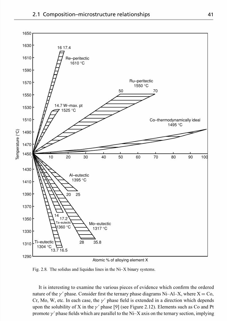
7/18/2019 The Superalloys Fundamentals and Applications
http://slidepdf.com/reader/full/the-superalloys-fundamentals-and-applications 59/389
2.1 Composition–microstructure relationships 41
16 17.4
1650
1630
1610
1590
1570
1550
1530
1510
1490
1470
1450
1430
T e m p e r a t u r e ( ° C )
1410
1390
1370
1350
1330
1310
1290
Re–peritectic1610 °C
10 20 30
Al–eutectic1395 °C
14.7 W–max. pt
1525 °C
Ru–peritectic1550 °C
Co–thermodynamically ideal1495 °C
Mo–eutectic1317 °C
Ti–eutectic1304 °C
13.7 16.5
28 35.8
Atomic % of alloying element X
20 25
1417.2
Ta–eutectic
1360 °C
40 50 60 70 80
50 70
90 1000
Fig. 2.8. The solidus and liquidus lines in the Ni–X binary systems.
It is interesting to examine the various pieces of evidence which confirm the ordered
nature of the γ phase. Consider first the ternary phase diagrams Ni–Al–X, where X= Co,
Cr, Mo, W, etc. In each case, the γ phase field is extended in a direction which depends
upon the solubility of X in the γ phase [9] (see Figure 2.12). Elements such as Co and Pt
promote γ phase fields which are parallel to the Ni–X axis on the ternary section, implying

7/18/2019 The Superalloys Fundamentals and Applications
http://slidepdf.com/reader/full/the-superalloys-fundamentals-and-applications 60/389
42 The physical metallurgy of nickel and its alloys
Fig. 2.9. Variation of the atomic diameter of the elements as a function of atomic number; also
given are data for the maximum solubility of each element X in FCC nickel. The horizontal linescorrespond to a ±15% deviation away from the atomic diameter of nickel. Note that significant
solubility occurs only when the atomic sizes of nickel and solute are comparable.
0 0.2 0.4 0.6 0.8 1
Atomic fraction Al
Subregularsolution model
AlNi
AlNi3
Al3Ni
2
Al3Ni
Al9Ni2
AINi
−60
−50
−40
−30
−20
−10
0
Δ H 1 ( k J / ( m o l a t o m ) )
Fig. 2.10. Variation of the enthalpy of formation, H f , for the various intermetallic compounds in
the binary Ni–Al system [8]. The broken line corresponds to the enthalpy of mixing of the
disordered FCC phase, with respect to the pure Ni and Al constituents.

7/18/2019 The Superalloys Fundamentals and Applications
http://slidepdf.com/reader/full/the-superalloys-fundamentals-and-applications 61/389
2.1 Composition–microstructure relationships 43
Fig. 2.11. Arrangements of Ni and Al atoms
in (a) the ordered Ni3Al phase and (b) after
disordering.
CoCu
PtSc
Fe Cr
Mn V
Ta
InSbSn
Mo,W
Hf,Nb,Zn
Ti
50 40 30
Ga
20 10 Ni
10
20
30
SiGe
X
A l
γ ′
Fig. 2.12. Superimposed ternary phase diagrams Ni–Al–X [9], illustrating the great effect of X on
the extent of the γ phase field.
a constant Al fraction and providing confirmation that substitution for Ni on the first of the
two sublattices is preferred. Elements such as Ti and Ta promote fields parallel to the Al–X
axis, and thus they replace Al on the second sublattice. Only rarely, for example, for Cr,
Fe and Mn, is mixed behaviour observed. The behaviour of the element X in this regard
depends rather strongly on its size relative to Ni and Al. The lattice parameter, a, of γ

7/18/2019 The Superalloys Fundamentals and Applications
http://slidepdf.com/reader/full/the-superalloys-fundamentals-and-applications 62/389
44 The physical metallurgy of nickel and its alloys
250
200
150
100
N u m b e r o f A I i o n s
50
0
0 200 400
Total number of detected ions
600 800 1000
Ni
Ni
Ni
Ni + Al
Ni + Al
Ni + Al
Al
Ni[001]
Fig. 2.13. Ladder diagram taken from a 001-orientated Ni3Al single crystal using atom probe field
ion microscopy. Courtesy of Kazihiro Hono.
at room temperature is 0.3570 nm, which is equivalent to the Al–Al distance; this is only
∼1.5% larger than the lattice parameter of pure Ni, which is 0.3517 nm. The Ni–Al distance
is a/√
2, or 0.2524 nm. Thus substitution for Al is favoured by large elements such as Ta
and Ti, whereas smaller atoms such as Co substitute for Ni.
Direct evidence of the ordered nature of γ comes from experiments carried out using
the atom probe, which consists of a field ion microscope coupled to a mass spectrometer. In
these experiments, atoms are evaporated in the form of ions from a specimen sharpened to
a radius of a few nanometres; a channel plate is used to select an appropriate pole, and the
atoms are identified by measuring the time-of-flight to the detector, which depends uniquely
on the charge-to-mass ratio. The sequential stripping of atoms from a series of {200} planes
allows a ladder diagram to be built up [10] (see Figure 2.13), on which the total number of
Al ions detected during the run is plotted against the total number of ions collected. The
mean gradient of the line is one-quarter, but during the stripping of mixed Ni/Al and Ni
planes the gradient changes to one-half and zero, respectively. These features of the ladder
diagram provide very elegant and direct proof of the ordering of theγ phase on the atomic
scale.
Does the γ remain ordered until the melting temperature is reached? Disordering is
a possibility which should be considered as the entropy contribution to the Gibbs energy
becomes larger as the temperature is raised. For many years this question remained unan-
swered, but it is now known that the ordering temperature of Ni3Al is roughly equivalent
to its melting temperature of about 1375◦C, although it does depend strongly upon the
degree of stoichiometry and the concentrations of any impurities. This has been demon-strated [11] by doping Ni3Al with varying amounts of Fe, which weakens the ordering; this
lowers the critical ordering temperature, which can then be measured using dilatometry
(see Figure 2.14). The ordering temperature of pure stoichiometric Ni3Al is then estimated
by extrapolation of the data to zero iron content; the result of ∼1375 ◦C must be termed
‘virtual’ since it lies above the melting point. In fact, evidence of the disordering of Ni3Al

7/18/2019 The Superalloys Fundamentals and Applications
http://slidepdf.com/reader/full/the-superalloys-fundamentals-and-applications 63/389
2.1 Composition–microstructure relationships 45
Atomic %Fe
0 7 10 12.51150
1200
1250
1300
1350
1400
T e m p e r a t u r e ( ° C
)
1375 °CSolidus and liquidus range
Fig. 2.14. Variation of the ordering
temperature of Ni3Al when doped with Fe
[11]. Note that the ordering temperature of
pure Ni3Al can be deduced by extrapolation
to zero Fe content.
10−5
10−6
10−4
10−3
I n t e g r a t e d r e f l e c t i n g p o w e r
Temperature (°C)
2000 400 600 800 1000 1200 1400
{200} fundamental
{100} superlattice
T mFig. 2.15. Temperature dependence of the
intensity of two diffraction lines from a Ni3Al
crystal, containing slightly less than 25at%Al
[12].
has been observed [12] using high-temperature neutron diffractometry; see Figure 2.15.
In the vicinity of the melting temperature, the intensity of the
{100
}superlattice reflection
drops sharply – implying the onset of disordering before the melting temperature is reached.
Binary Ni–Al alloys of composition consistent with a two-phase γ/γ microstructure
exhibit γ precipitates which are often cuboidal in form [13] (see Figure 2.16). Analysis of
these structures using transmission electron microscopy confirms that a distinct cube–cube
orientation relationship exists between theγ precipitates and γ matrix in which they reside
(see Figure 2.17). Since the lattice parameters of the disordered γ and ordered γ phases
are very similar, the electron diffraction patterns exhibit maxima which are common, for
example, from the {110}, {200}, {220} reflections, and others which are due only to γ , for
example, {100}, {210} etc. The orientation relationship can be described by
{100}γ //{100}γ 010γ //010γ (2.5)
which is referred to as the cube–cube orientation relationship. Theγ /γ interfaces have the
001 directions as their plane normals. Provided that the lattice misfit between the lattice

7/18/2019 The Superalloys Fundamentals and Applications
http://slidepdf.com/reader/full/the-superalloys-fundamentals-and-applications 64/389
46 The physical metallurgy of nickel and its alloys
Fig. 2.16. Dark-field transmission electron
micrograph of γ precipitates in a Ni–
13.4 at%Al alloy, aged at 640 ◦C for
1000h [13].
Fig. 2.17. Selected area diffraction patterns
taken in the transmission electron microscope
of a single-crystal superalloy, with foil normal
close to 001, (a) of the disordered γ and
(b) of both the ordered γ and disordered γ ,with superlattice reflections.
parameters of the γ and γ phases is not too large, the γ/γ interface remains coherent and
the interfacial energy remains low. The γ precipitates often align along the elastically soft
100 direction (see Figure 2.16).
The properties of the superalloys are found to depend critically on the coherency of the
γ/γ interface. This is favoured by small values of the lattice misfit,δ, defined according to
δ = 2× aγ − aγ
aγ
+aγ (2.6)
which is thus negative if aγ < aγ and positive if the converse is true. Consistent with
Vegard’s law, one has relationships such asaγ = a0γ +
i
γ
i xγ
i and aγ = a0γ +
i
γ
i xγ
i
so that the lattice parameters are linear with the mole fractions of added solutes. The Vegard
coefficients γ
i and γ
i show a strong dependence on the position of i in the periodic
table (see Figure 2.18). Values are largest for elements from the far west and far east of

7/18/2019 The Superalloys Fundamentals and Applications
http://slidepdf.com/reader/full/the-superalloys-fundamentals-and-applications 65/389
2.1 Composition–microstructure relationships 47
11
10
9
9
8
8
(a)
(b)
7
7
6
6
5
5
4
4
3
3
2
2
1
1
0
0-1
M a g n i t u d e o f V e g a r d c o e f f i c i e n t ( n m / a
t % ) × 1 0 − 4
Position in period
Ti
Hf
Zr
Ta
Nb
Mo
WRe
Tc
Os
Ru
Ir
Pt
Pd
Au
Ag
Rh
5d
4d
3d
V
Cr
Mn
Fe
CoNi
Cu
11
10
9
9
8
8
7
7
6
6
5
5
4
4
3
3
2
2
1
1
0
0−1
M a g n i t u d e o f V e g a r d c o e f f i c i e n t ( n m / a
t % ) × 1 0 − 4
Position in period
Ti
Ta
Nb
Mo
W Re
Tc
Os
Ru
Ir
Pt
Pd
Rh
5d
4d
3d
V
Cr
Mn
Fe Co Ni
Hf
Zr
Fig. 2.18. Variation of the Vegard coefficients with position in the transition metal series: (a) for the
disordered FCC phase, γ , and (b) for the ordered Ni3Al phase, γ . Data from ref. [3].
the transition metal block, when the discrepancy in atomic size is largest. Moreover, the
lattice parameter of the γ phase shows the greater sensitivity to solute additions. The lattice
misfit, δ, then depends on two factors: (i) the partitioning of solutes i between γ and γ
and (ii) the corresponding influence of the solutes i on the lattice parameters consistent
with Vegard’s law. Coarsening of the γ particles leads to loss of coherency and an increase

7/18/2019 The Superalloys Fundamentals and Applications
http://slidepdf.com/reader/full/the-superalloys-fundamentals-and-applications 66/389
48 The physical metallurgy of nickel and its alloys
Fig. 2.19. Transmission electron microscope (TEM) image [14] showing γ precipitation in
Nimonic 115 aged at 1418 K for 24 h. Note (i) the central, initial cuboid from which the primary γ
particle has developed, (ii) the precipitate-free zone around it and (iii) the fine spherical dispersion
of γ formed upon cooling.
in the magnitude of δ. Thus a distinction should be drawn between the constrained and
unconstrained lattice misfit.
Ricks et al . [14] have studied the development of γ precipitates in a number of dif-
ferent nickel-based superalloys during heat treatment, identifying correlations between the
morphology, size and sign of the γ /γ misfit (see Figure 2.19). It was shown that the
morphological development occurs in the sequence spheres, cubes, arrays of cubes and
eventually solid-state dendrites as coarsening is promoted by ageing (see Figure 2.20). No
substantial difference in this respect was found between positive and negative misfitting
alloys, although in the latter case the {001} facets were better defined and interfacial dis-
location networks were found to develop at an earlier stage in the γ growth sequence.
Interestingly, both the size at which the γ particles depart from the spherical morphology
and the severity of the heat treatment required to form the cuboidal arrays were found to
be sensitive functions of the lattice misfit; thus, for alloys of low misfit the size of the γ particle needs to be larger before the effects of misfit strain are sufficient to influence the
particle shape. For the Nimonic alloys 80A, 90, 105 and 115, for which convergent beam
electron diffraction (CBED) was used to estimate the room-temperature misfits at+0.32%,
+0.34%, −0.04% and −0.18%, respectively, the γ precipitate sizes at which significant
departure from the spherical shape was observed were found in turn to be 0.3, 0.3, 0.7 and

7/18/2019 The Superalloys Fundamentals and Applications
http://slidepdf.com/reader/full/the-superalloys-fundamentals-and-applications 67/389
2.1 Composition–microstructure relationships 49
Fig. 2.20. Schematic diagram illustrating the development, from (a) to (f), of strain-induced, faceted
γ morphologies during ageing: left, projection along 111; right, projection along 001. Adapted from ref. [14].
0.5 μ m. This suggests that when the magnitude of the misfit is small, theγ particles must
grow to a larger size before the cuboidal form is found.
2.1.3 Other phases in the superalloys
A The gamma double prime phase
In nickel–iron superalloys such as IN718 and IN706, which contain quantities of niobium,
the primary strengthening precipitate is notγ but instead a body-centred tetragonal (BCT)
ordered compound; this displays the D022 crystal structure and a composition which can be
represented approximately by Ni3 Nb. In IN718, the lattice parameters are approximately
c = 0.740nm and a = 0.362 nm [15]. The unit cell is shown in Figure 2.21. One can see

7/18/2019 The Superalloys Fundamentals and Applications
http://slidepdf.com/reader/full/the-superalloys-fundamentals-and-applications 68/389
50 The physical metallurgy of nickel and its alloys
Fig. 2.21. The unit cell of the γ precipitate
which is found in iron–nickel superalloys
such as IN718 and IN706.
that the arrangement of the atoms is related to that of the L12 structure of the γ phase; in
fact the a parameter is close to that displayed byγ but the c parameter is roughly doubled.
Because of this similarity with γ , one refers to this phase as γ . As with γ , a distinct
orientation relationship with the matrix phase γ is displayed, such that 001γ //001γ and 100γ //100γ . The γ displays a disc-shaped morphology, with the thickness often
as small as 10 nm and the diameter about 50 nm (see Figure 2.22). The particles are usually
found to be coherent with the matrix, with coherency strains equivalent to several per
cent. The excellent high-temperature properties of IN718 – which is used very widely in
polycrystalline cast-and-wrought form to operating temperatures approaching 650◦C on
account of its relatively low cost – are due to the coherency strains so imparted and the
limited number of available slip systems which operate in γ . The kinetics of formation of
γ are sluggish as a consequence of the high coherency strains.
Nickel–iron alloys which are strengthened by γ are susceptible to the formation of
an orthorhombic δ phase in the overaged condition [16,17]. This is invariably incoherent
with γ , and therefore does not confer strength even when present in significant quantities.
It forms in the temperature range 650 to 980◦C, but the characteristics of its formation
depend strongly upon temperature. Below 700◦C, nucleation of δ is observed at γ –grain boundaries and growth occurs at the expense of γ . In the range700◦Cto885 ◦C, formation
of δ is accompanied by rapid coarsening of γ ; beyond the solvus temperature of 885◦C γ
is no longer stable. At temperatures between 840◦C and 950 ◦C, the plates of δ form rapidly
in times less than 24 h. The δ solvus temperature is ∼1000 ◦C. It should be emphasised,
however, that the kinetics of formation of δ are strongly accelerated if forging is carried

7/18/2019 The Superalloys Fundamentals and Applications
http://slidepdf.com/reader/full/the-superalloys-fundamentals-and-applications 69/389
2.1 Composition–microstructure relationships 51
Fig. 2.22. Transmission electron micrographs [17] showing the γ and γ phases in the IN706 alloy
aged at 732 ◦C for 16 h: (a) bright-field image, (b) diffraction pattern, (c) dark-field image using spot
1 and (d) dark-field image using spot 2.
out below the δ solvus; the resultant δ-phase distribution can be used to control and refine
the grain size to help optimise the tensile and fatigue properties. However, the formation of
extensive amounts of δ during service leads to severe degradation of properties and is to be
avoided.
B The TCP phases
Excessive quantities of Cr, Mo, W and Re promote the precipitation of intermetallic phaseswhich are rich in these elements [18] (see Figure 2.23). The resulting phases have a number
of distinct characteristics: (i) a high and uniform packing density of atoms, (ii) a degree
of non-metallic, directional bonding and (iii) complex crystal structures, each built up of
distinct tessellated layers consisting of arrays of hexagons, pentagons and triangles (see
Figure 2.24) stacked into a limited number of so-called Kasper co-ordination polyhedra

7/18/2019 The Superalloys Fundamentals and Applications
http://slidepdf.com/reader/full/the-superalloys-fundamentals-and-applications 70/389
52 The physical metallurgy of nickel and its alloys
Fig. 2.23. Scanning electron micrograph of the superalloy RR1000 showing extensive precipitation
of the σ phase at γ –grain boundaries, after a heat treatment of 5000 h at 750 ◦C. Courtesy of Rob
Mitchell.
z = 0
z = 1/4
z = 1/2
z = 3/4
x
y
x
y
Fig. 2.24. The unit cell of the P phase showing the primary and secondary layers. For clarity, all
atoms are represented by circles of the same size. Adapted from ref. [19].
[19]. This last fact gives rise to the name topologically close-packed , or TCP, phases.
Generally speaking, the TCP phases have chemical formulae A x B y , where A and B are
transition metals, such that A falls to one side of the group VIIB column defined by Mn,Tc and Re (see Figure 1.21) and B falls to the other [19]. Theμ phase is based on the ideal
stoichiometry A6B7 and has a rhombohedral cell containing 13 atoms; examples include
W6Co7 and Mo6Co7. The σ phase is based upon the stoichiometry A2B and has a tetragonal
cell containing 30 atoms; examples include Cr 2Ru, Cr 61Co39 and Re67Mo33. The P phase,
for example, Cr 18Mo42 Ni40 is primitive orthorhombic, containing 56 atoms per cell. Finally,

7/18/2019 The Superalloys Fundamentals and Applications
http://slidepdf.com/reader/full/the-superalloys-fundamentals-and-applications 71/389
2.1 Composition–microstructure relationships 53
Fig. 2.25. Example of a blocky MC carbide formed in an experimental nickel-based single-crystal
superalloy [20].
the R phase, for example, Fe52Mn16Mo32, has a rhombohedral cell containing 53 atoms.
It should be emphasised that the TCP phases can have very different compositions from
those quoted here, and that the stoichiometry ranges are often very wide. However, the fact
that the crystal structures are based upon A x B y , with A and B thus displaying differentelectronegativities, suggests that electronic factors are important in determining stability, in
an analogous way to the ‘electronic compounds’ of Hume-Rothery in alloys which contain
combinations of Cu, Ag and Au.
C Carbide and boride phases
Various carbide and boride species form in the superalloys, the type depending upon the
alloy composition and the processing conditions employed. Some of the more important
types include MC, M6C, M23C6, M7C3 and M3B2, where M stands for a metal atom such
as Cr, Mo, Ti, Ta or Hf. In many superalloys the MC carbide, which is usually rich in Ti,
Ta and/or Hf since these are strong carbide formers, precipitates at high temperatures from
the liquid phase. Consequently, the carbide is often found in interdendritic regions and no
distinct orientation relationship with thematrix is displayed. A number of morphologies, for
example, globular, blocky and script have been reported [20] (see Figure 2.25). Carbides
such as M23C6 form at lower temperatures – around 750◦C – during protracted periods
of service exposure, particularly in alloys which are rich in Cr. Their formation has been
attributed to the breakdown of the MC carbides, via reactions of the type
MC+ γ → M23C6 + γ (2.7)
The M23C6 carbide is usually found to precipitate on theγ –grain boundaries. The complex
cubic structure exhibited by this phase is, in fact, closely related to that of σ – with the
carbon atoms removed, the crystal structures resemble each other [18]. This fact explains

7/18/2019 The Superalloys Fundamentals and Applications
http://slidepdf.com/reader/full/the-superalloys-fundamentals-and-applications 72/389
54 The physical metallurgy of nickel and its alloys
Fig. 2.26. Precipitation of the M23C6 carbide on the γ –grain boundary in an experimental
second-generation single-crystal superalloy doped with carbon and boron and crept at 950 ◦C and
290 MPa [21]: (a) scanning electron micrograph; (b) transmission electron micrograph and
diffraction pattern identifying the M23C6 carbide; (c) dimpled fracture surface of creep specimen,
showing evidence of ductile failure mode.
why σ is found to nucleate sympathetically from M23C6 in polycrystalline turbine disc
alloys such as Udimet 720Li and RR1000.
The role of carbides and borides has proved controversial, but it is now accepted that the
high-temperature creep properties of the superalloys are improved in many circumstances
if carbon and boron are present; the formation of these phases is then very likely. This is
primarily due to the preferred location of carbon, boron, carbides and borides at theγ –
grain boundaries, which has a potent effect on the rupture strength via the inhibition of
grain-boundary sliding. Thus, carbon and boron are often referred to as grain-boundary
strengtheners. This explains why carbon and boron levels are generally higher in polycrys-
talline or columnar-grained superalloys used in cast form, and the absence of these elements
in the single-crystal superalloys, for which grain-boundary strengthening is unnecessary.
The benefits of doping with carbon and boron when grain boundaries are present has been
confirmed byChen andKnowles [21], who testedan experimental second-generation single-crystal superalloy in creep at 950◦C and 290 MPa. When grain boundaries of misorientation
equal to 10◦ were introduced, carbon and boron concentrations of 0.09 and 0.01 wt%, re-
spectively, were sufficient to improve the rupture life from 10 h to 100 h. This effect was
attributed to small, coherent and closely spaced M23C6 carbides precipitating on the grain
boundaries (see Figure 2.26).

7/18/2019 The Superalloys Fundamentals and Applications
http://slidepdf.com/reader/full/the-superalloys-fundamentals-and-applications 73/389
2.2 Defects in nickel and its alloys 55
2.2 Defects in nickel and its alloys
A nickel alloy, despite being a crystalline solid, possesses a number of intrinsic defects
present on the scale of the lattice. One can distinguish between (i) planar defects such as
stacking faults, (ii) line defects such as dislocations and (iii) point defects, for example,
vacancies, interstitials and anti-site defects. In turns out that the mechanical properties
displayed by the superalloys are strongly dependent upon the type and concentration of
defects which occur. In this section, consideration is given to the details of the defects
which arise and to some of the implications of their presence.
2.2.1 Defects in the gamma (FCC) phase
The face-centred cubic (FCC) structure consists of close-packed planes, stacked with peri-
odicityequal to three.Thus thelattice, if it isperfect,can bedenotedABCABCABCABC. . . ,
where each of A, B or C represents a close-packed layer; this contrasts with the hexagonally
close-packed (HCP) structure, which is denoted ABABABABAB. . . Since the lattice vector
is a/√
2, where a is the length of the side of the unit cell, one can demonstrate that two
consecutive close-packed layers are displaced by a vector of magnitudea/√
6, measured
within a close-packed plane. The spacing of the close-packed planes isa/√
3.
A Planar defects – the stacking fault
A stacking fault arises when the stacking sequence ABCABCABCABC. . . is inter-
rupted [22]. The removal of one plane introduces an intrinsic stacking fault, for exam-
ple, ABCACABCABC. . . , and causes two neighbouring planes to possess the HCP
co-ordination locally. Conversely, theaddition of one plane introduces an extrinsic stacking
fault, for example, ABCACBCABCABC. . . Although two HCP planes are again intro-
duced, these are separated by a single plane of FCC co-ordination, and are thus a distance
2a/√ 3 apart – a spacing corresponding to two lattice planes.
B Line defects – dislocations
In a macroscopic sense, the slip system in an FCC metal such as Ni is a/2110{111};hence the Burgers vector is a/
√ 2. However, this statement does not properly respect the
micromechanics of deformation; it is well established that the glide of an a/2110{111}dislocation occurs by the passage of two partial dislocations, which, although in close prox-
imity to each other, are separated by a distance which depends upon the force of their elasticrepulsion and the energy of the planar stacking fault so produced (see Figure 2.27). This
implies that the a/2110{111} dislocations are dissociated; electron microscopy confirms
that the reaction is of the form
a
2110{111} → a
6211{111} + a
6121{111} (2.8)

7/18/2019 The Superalloys Fundamentals and Applications
http://slidepdf.com/reader/full/the-superalloys-fundamentals-and-applications 74/389
56 The physical metallurgy of nickel and its alloys
16
[121]
12
[011] 16
[211]
16 [121]b 2 =
16 [112]b 1 =l l
B B
BB
BB
B B
B
B
B
BB
C C
C C
C C
Fig. 2.27. Dislocation on a {111} plane of γ , dissociated into two Shockley partial dislocations [22].
A
A
A A A
A
B′
C
B
Fig. 2.28. Geometry of the close-packed
plane, appropriate for the dissociation into
Shockley partials; the large arrow
corresponds to a2110, and the smaller
arrows correspond to a6211 and a
6121.
where each dislocation on the right-hand side of the equation is known as a Shockley partial.
The magnitude of the Burgers vector of each is a/√
6, equivalent to the displacement of
two neighbouring close-packed planes in the perfect FCC crystal (see Figure 2.28). Thus
the passage of a single Shockley partial dislocation causes the introduction of an intrinsic
stacking fault, which is removed by the action of the second – hence the width of the
stacking fault depends upon the spacing of the partials. The reader can readily apply Frank’s
rule, which states that the elastic energy of a dislocation is proportional to the square of
the magnitude of the Burgers vector, to confirm that the dissociation of Equation (2.8) is
energetically favourable.
It isof interest todetermine therelationship between thespacing of the partialdislocations
and the stacking fault energy (SFE) – the energy per unit areaof the planar defectbetween thetwo partials, denoted γ SF. Consider the dissociationof an edge dislocation (Figure 2.29). The
spacing of the partials is given the symbold ; each has a Burgers vector of magnitudea/√
6,
which can be resolved into an edge component, a cos{π/6}/√
6, and a screw component,
a sin{π/6}/√
6, π/6 being the angle between the Burgers vectors of the dissociated and
undissociated dislocations. It follows from the geometry of the situation, see Figure 2.29,

7/18/2019 The Superalloys Fundamentals and Applications
http://slidepdf.com/reader/full/the-superalloys-fundamentals-and-applications 75/389
2.2 Defects in nickel and its alloys 57
π 6
π6
g g
a √2
2b =
d
Screw Screw
Edge Edge
Stackingfault
Fig. 2.29. Schematic illustration of the dissociation of an edge dislocation into two Shockley partial
dislocations, which are in turn resolved into their edge and screw components.
that the screw components of the dissociated dislocations are of opposite sense so that they
provide an attractive force complementing that due to the stacking fault energy. On the other
hand, the edge components are of equivalent sign and thus repel each other; it is this effect
which provides the driving force for dissociation.
The force balance consists therefore of three terms, the repulsive force per unit length of
dislocation due to the edge components of the partials, balanced at equilibrium by attractiveforces per unit length arising from the screw components and the stacking fault energy
itself. It is given by
γ SF +Gb2
s
2πd = Gb2
e
2πd (1− ν)(2.9)
where be and bs are the edge and screw components of the partials of magnitude
a cos{π/6}/√
6 and a sin{π/6}/√
6, respectively, G is the shear modulus and ν is Pois-
son’s ratio. Note that isotropic elasticity is assumed to hold. The forces Gb2s/2πd and Gb2
e/2πd (1− ν) arise from the shear stresses Gbs/2πd and Gbe/2πd (1− ν) acting at a
distance d from the centres of perfect screw and edge dislocations, respectively, as given
by elementary dislocation theory; the forces per unit length,F , are obtained by multiplying
by the appropriate shear stress, τ , by the corresponding Burgers vector, b, consistent with
F = τ b. After some algebraic manipulation, one can show that the spacing of the partials

7/18/2019 The Superalloys Fundamentals and Applications
http://slidepdf.com/reader/full/the-superalloys-fundamentals-and-applications 76/389
58 The physical metallurgy of nickel and its alloys
10−10
10−11
10−12
10−13
10−14
10−3 10−2 10−1
kT
D mb
g SF
mb
Al
Pb
Nig Fe
Ni 10 Cr
Ni 20 CrNi 24 Cr
Ni 81 Fe
Ni 12 Fe
Ni 26 FeNi 61 Fe
Ni 2WNi 41 Fe
Ni 30 CrNi 13 Cu
Ni 79 Cu
AuPtCu
Ag
Cu
Cu 20 ZnCu 30 Zn
10 Zn
= 2 × 10⁻⁴s
m
∋
Fig. 2.30. Correlation between the normalised steady-state creep rate, , and the stacking fault
energy, γ SF, for a number of solid-solution-strengthened alloys [23].
is given by
d = Ga 2
48πγ SF
2+ ν
1− ν
(2.10)
the important result being that the spacing,d , is inversely proportional to the stacking fault
energy,γ SF. All dislocations, whether edge, screw or mixed, are dissociated in this way. It can
be demonstrated by the reader that if a screw rather than an edge dislocation is considered,
the spacing, d , is reduced by a factor (2− 3ν)/(2+ ν), which is approximately one-half if
ν = 0.33.For high-temperature applications, the magnitude of the stacking fault energy is an
important consideration. This is because screw portions of perfect dislocations, dissociated
into their Shockley partials, must constrict locally if they are to cross-slip. This is a common
mechanism by which obstacles such as precipitates can be circumvented. On this basis,
widely spaced partials arising from low values of γ SF are advantageous to high-temperature

7/18/2019 The Superalloys Fundamentals and Applications
http://slidepdf.com/reader/full/the-superalloys-fundamentals-and-applications 77/389
2.2 Defects in nickel and its alloys 59
properties; this has been confirmed by the work of Mohamed and Langdon [23], who
measured the steady-state creep rate, , of a number of solid-solution-strengthened nickel
alloys (see Figure 2.30). A correlation between the parameter kT /( DGb) was found,
where D is the diffusion coefficient, and the stacking fault energy,γ SF, normalised by Gb.
Transmission electron microscopy studies have confirmed a strong influence of alloying
elements on the stacking fault energy. See, for example, the data [24] for Ni–Co alloys
(Figure 2.31), which indicates thatγ SF decreases from about 250 mJ/m2 for pure Ni to less
than half this value for an alloy of composition Ni–50wt%Co. It appears, however, that
there have been no systematic attempts to correlate the influence of stacking fault energy
on the type of solute, although Delehouzee and Deruyttere [25] have measured the stacking
fault probability, α, a measure of the number of stacking faults existing in a metal, from
the broadening and shifting of diffraction peaks using X-ray methods; this is expected to be
inversely proportional to γ SF. Their results are given in Figure 2.32. The slope of the linescorrelate strongly with the valency difference between Ni and the solute being added. Given
these results, on the basis of at% solute added one would expect elements such as Ti, which
lie at the far left of the d block of transition metals, to have the greatest effect onγ SF and the
high-temperature properties which are influenced by it. Such alloying effects are important
since Ni itself has one of the largest stacking fault energies of the FCC metals at 250 mJ/m2;
by contrast, for Al, Cu, Au and Ag the values are approximately 200, 55, 50 and 22 mJ/m2,
respectively. Thus the partial dislocations in unalloyed Ni are relatively closely spaced.
C Point defects – vacancies
Vacancies are present in the lattice of high-purity Ni, because the increase in free energy
caused by the breaking of bonds is more than offset by the term due to the configurational
entropy which then arises. From statistical mechanics one expects the equilibrium vacancy
fraction, f eq Va , to be given by
f eq Va
=exp−
G f Va
RT =
exp+S
f Va
R×
exp− H
f Va
RT (2.11)
where G f Va, H
f Va and S
f Va are, respectively, the Gibbs energy, enthalpy and en-
tropy of formation of a vacancy. For most metals, the pre-exponential term given by
exp+S
f Va/ R
lies between 1 and 10, and is nearly invariant with temperature. Elec-
trical resistivity measurements on quenched and quenched/tempered nickel [26] indicate
that H f
Va is ∼160 kJ/mol; taking the pre-exponential term as 5, this gives a fraction f of
10−28 at ambient temperature, rising to 8.5× 10⁻⁵ at the melting temperature of 1455◦C.
This value is comparable to other FCC metals; for example, for Al, Au and Ag the enthalpies
H f
Va are 65 kJ/mol, 85 kJ/mol and 107 kJ/mol, respectively, so that f eq Va is 9.4× 10⁻⁴,
7.2× 10⁻⁵ and 1.7× 10⁻⁵ at the melting temperature of the metal concerned.
The presence of vacancies can be inferred directly from measurements of the lattice
spacing and thermal expansion coefficient, i.e. using a combination of diffractometry and
dilatometry. This is because one atomic site is added each time a vacancy is created at a free
surface, grain boundary or dislocation. The corresponding changes in the dimensions of the

7/18/2019 The Superalloys Fundamentals and Applications
http://slidepdf.com/reader/full/the-superalloys-fundamentals-and-applications 78/389
60 The physical metallurgy of nickel and its alloys
Ni
2
5
10
20
50
γ S F
( m J / m 2 )
100
200
500
10 20 30 40 50 60 70
wt%Co
Fig. 2.31. Variation of the stacking fault energy, γ SF, with composition for a number of binary
Ni–Co alloys [24].
specimen will be detectable by dilatometry; however, if internal stresses can be ignored, the
lattice spacing will not be altered substantially. To illustrate this, consider a one-dimensional
analogy: a perfect row of N atoms of spacing a0 which is heated from T 0 to T 1, causing (i)
the formation of n vacancies such that n N and (ii) a change in length from L0 to L1.
The expansion L = L1 − L0 has two contributions: the first is due to the increase in the
periodicity from a0 to a1 due to the thermal expansion, denoted a, and the second is due
to the introduction of the vacancies. Hence,
L = ( N ×a)+ (n × a1) (2.12)
Dividing through by N a1 ∼ L1 and rearranging, one has
f eq Va =
n
N = L
L1
− a
a1
(2.13)
For metals, this simple estimate is, in fact, in error by a factor of 3, since one has in reality a
three-dimensional rather than a one-dimensional lattice; thefraction f eq Va is then given instead
by 3( L/ L1 −a/a1). Small errors are expected due to strain relaxation effects and the
possibility of vacancy clustering to form divacancies; nevertheless, 3( L/ L1 −a/a1) is
usually found to be of the order 10−4 for most metals [27]; see Figure 2.33.
The presence of vacancies in the nickel alloys is of great significance, since they mediate
the diffusional flow required for a number ofphenomena: creep occurring ata rate dependentupondiffusional rearrangements at dislocation cores, coarseningof theγ precipitates on the
scale of their periodicity, and oxidation, which occurs at a rate which is diffusion-controlled;
clearly, the retardation of diffusional processes is important if the very best properties are to
be attained. Consider the self-diffusion of nickel. The diffusion coefficient,Dself Ni , depends
on two factors:

7/18/2019 The Superalloys Fundamentals and Applications
http://slidepdf.com/reader/full/the-superalloys-fundamentals-and-applications 79/389
2.2 Defects in nickel and its alloys 61
0 10 20 30 40 50
(b)
60 700
5
10
15
20
25
Atomic % solute
a
× 1 0 3
(a)
Ti
Mo
W
V Cr
Mn
Co
Cu
Fe
0
10
20
30
1 2 3 4
102
5 ΔZ
Ni − Fe
Ni − Co
Ni − Mn
Ni − Cr
Ni − V
Ni − W
Ni − Ti
Fig. 2.32. For a number of binary nickel alloys [25]: (a) variation of the stacking fault probability
with solute content, and (b) correlation of the slope of (a) at zero solute content, with the difference
between the valency of nickel and solute denoted Z .
(i) the rate of successful atom–vacancy exchanges, denoted Va, which is given by
Va = νo exp
− E
mig
Ni−Va
RT
(2.14)
where νo is an attempt frequency and E mig
Ni−Va is an activation energy associated with

7/18/2019 The Superalloys Fundamentals and Applications
http://slidepdf.com/reader/full/the-superalloys-fundamentals-and-applications 80/389
62 The physical metallurgy of nickel and its alloys
250
6
8
10
12
14
16
18
300 350 400 450 500 550 600 650
Temperature (°C)
ΔLL
Δa a
Δ L L
Δ a a
o r
( x 1 0 3 )
Fig. 2.33. Effects of changes in length and lattice parameter with temperature [27].
the migration of a nickel atom into a neighbouring vacant site, through a distancea/√
2
along the lattice vector 110, past the saddle point;
(ii) the probability that the neighbouring site is vacant. This is numerically equivalent to
the fractional concentration of lattice vacancies in thermal equilibrium with the lattice,
as given by Equation (2.11).
One has therefore, to a first approximation,
Dself Ni = λ2νo exp
+S
f Va +S
mig
Ni−Va
R
× exp
− H
f Va + H
mig
Ni−Va
RT
(2.15)
where the activation energy, E mig, has been partitioned into its enthalpy and entropy
components, H mig and S mig, respectively. The term λ is the characteristic jump distance
given by a/√
2. One can see that the apparent activation energy for self-diffusion,Qself , is
composed of two terms, such that
Qself
= H
f Va
+ H
mig
Ni−Va
(2.16)
The experimental measurements indicate that Qself ∼ 280 kJ/mol [28]. Hence,
H mig
Ni−Va ∼ 120 kJ/mol, given the value of H f
Va quoted above. This value is associated
with the opening of the diffusion window along110.The presence of vacancies influences the rate of diffusion of substitutional solutes in
nickel. The rate of interdiffusion of the 4d and 5d transition metals has been studied

7/18/2019 The Superalloys Fundamentals and Applications
http://slidepdf.com/reader/full/the-superalloys-fundamentals-and-applications 81/389
2.2 Defects in nickel and its alloys 63
4010−12
10−13
10−14
10−15
10−16
10−17
10−18
41 42
4d series(a)
(b)
(c)
43 44 45 46 47
1300 °C
1300 °C
1200 °C
1100 °C
1000 °C
900 °C
1200 °C
1100 °C
1000 °C
900 °C
10−12
10−13
10−14
10−15
10−16
10−17
10−18
5d series
Zr
Hf
Ta
Nb W
720.125
0.130
0.135
0.140
0.145
0.150
0.155
0.160
73 74 G o l d s c h m i d t
a t o m i c r a d i u s ( n m )
75
Atomic number
76 77 78 79
Re
Tc Ru RhPd
Ag
Au
Pt
IrOsMo
D i n N i ( m 2 / s )
D i n N i ( m 2 / s
)
Fig. 2.34. Measurements of the interdiffusion coefficient in binary Ni/Ni–X diffusion couples:
(a) for the 4d series of the d block of transition metals, (b) for the 5d series, and (c) variation of the
Goldschmidt radius of the transition metals with atomic number [29,30].
experimentally [29,30], by analysing diffusion couples fabricated from Ni and Ni–X al-
loys, where X is a transition metal. Elements near the centre of the d block of the periodic
table, for example, Re and Ru, were found to diffuse several orders of magnitude more
slowly than those from the far west or far east of the d block, for example, Hf and Au; see
Figure 2.34. These experimental results are interesting, since they disprove the widely held

7/18/2019 The Superalloys Fundamentals and Applications
http://slidepdf.com/reader/full/the-superalloys-fundamentals-and-applications 82/389
64 The physical metallurgy of nickel and its alloys
360
320
280
240
200
160
120
40 41 42 43 44 45 46 47
A c t i v a t i o n e n e r g y
( k J / m o l )
5d
4d
240
200
160
120
80
40
E n e r g y ( k J / m o l )
240
200
160
120
80
40
E n e r g y ( k J / m o l )
Zr Nb Mo Tc Ru Rh Pd Ag
E b
E b
E Vaf
E Vaf
Hf Ta W Re Os Ir Pt Au
72 73 74 75 76 77 78 79
Atomic number
(a)
(b)
(c)
Fig. 2.35. Results of calculations from a model of the diffusion behaviour of the 4d and 5d
transition metals in nickel [31,32]: (a) the activation energy for diffusion, and the partition of it into
vacancy and barrier energy terms for the 4d and 5d solutes in (b) and (c), respectively.
view that diffusion is least rapid when the lattice misfit between solute and solvent atom radiiis the greatest. These observations have been rationalised using quantum-mechanical mod-
elling using first principles methods [31,32]; this has allowed an evaluation of the activation
energies for solute–vacancy exchange, denoted E b, and the vacancy formation energy for
a solute–vacancy complex, denoted E f
X−Va. The calculations indicate (see Figure 2.35) that
E f
X−Va does not vary strongly as one crosses the d block and by no more than 40 kJ/mol; in

7/18/2019 The Superalloys Fundamentals and Applications
http://slidepdf.com/reader/full/the-superalloys-fundamentals-and-applications 83/389
2.2 Defects in nickel and its alloys 65
fact, the magnitudes of E f
Hf −Va and E f
Au−Va are close to 120 kJ/mol, and thus are close to the
vacancy formation energy in pure Ni, implying that the solute–vacancy binding energy for
elements such as Hf and Au is negligible. The Re–Va binding energy is about+40kJ/mol.
Thus, the dependence of E f
X−Vaon atomic number is relatively weak. Instead, the major
contribution to the variation of the interdiffusion coefficient with atomic number arises
from the diffusion energy barrier, E b. This is significant for elements such as Re and Ru.
Alloying with these elements, which are amongst the densest in the d block owing to their
electronic bonding and many unpaired electrons, causes directional and incompressible Ni–
Re and Ni–Ru bonds which do not favour solute–vacancy exchanges. This effect dominates
any influences of atomic radius, misfit strain and differences in the solute–vacancy binding
energy. It is probable that this is the reason why Re has such a significant effect on the
high-temperature properties of the superalloys.
2.2.2 Defects in the gamma prime phase
A Planar defects – the anti-phase boundary
An important planar defect found in the nickel alloys is the anti-phase boundary, the
meaning of which can be understood in the following way. Consider two perfect crystals of
γ displaced by a/2101; this vector links neighbouring Ni and Al atoms, but note that it is
not a lattice vector. When bonded together, an interface known as the anti-phase boundary
(APB) separates the otherwise perfect lattices; in the vicinity of the APB, the number of
Ni–Al bonds is substantially reduced since ‘forbidden’ Ni–Ni and Al–Al bonds are formed
there. The net effect is to cause an APB energy which is substantial – usually of order
100 mJ/m2. The number of forbidden bonds is found to depend upon the crystallographic
plane on which the APB resides [33] (see Figure 2.36); consequently, for this reason, the
APB energy is anisotropic. This can be rationalised as follows. First, consider two {111} planes of the L12 structure stacked perfectly (Figure2.37)– note that there are no instances in
which two Al atoms are nearest neighbours. Upon displacing the second layer bya/2110,forbidden bonds are created: one is formed for each area, a
√ 2/2
×a√
6/2 or a2√
3/2.
The APB energy on the {111} plane is then 2/(a2√ 3), where is the ordering energy,
defined by = NiAl − 12( NiNi +AlAl), where NiAl, AlAl and NiNi are the Ni–Al,
Al–Al and Ni–Ni bond energies, respectively. Consider next the{110} plane (Figure 2.38).
One forbidden bond is formed per area a × a√
2/2 or a2√
2/2 so that the APB energy is
2/(a2√
2),whichisabout23%higherthanforanAPBonthe{111} plane. Finally, consider
the APB energy on the {001} plane. In this case, Figure 2.36 confirms that a translation
of a/2110 does not cause forbidden bonds; one way to realise this is to consider the
{200} planes, every second one of which consists solely of Ni atoms. It follows then that
Al atoms are never brought into nearest-neighbour positions, so that the APB energy will be close to zero. In practice, the APB energy on the {001} plane is non-zero; it should be
remembered that here only first-order nearest-neighbour bonding has been accounted for
in these arguments.
The planar fault known as the APB is of profound importance in superalloy metallurgy.
This is because theγ phase deforms very differently from the disordered γ matrix in which

7/18/2019 The Superalloys Fundamentals and Applications
http://slidepdf.com/reader/full/the-superalloys-fundamentals-and-applications 84/389
66 The physical metallurgy of nickel and its alloys
(a)
(c)
(b)
(d)
Fig. 2.36. Structure of the perfect L12 lattice, and anti-phase boundary (APB) structures caused by
the APB fault lying on different planes. (a) The ordered L12 structure; (b) (111)[110] anti-phase
boundary in the L12 structure; (c) (110)[110] anti-phase boundary in the L12 structure;
(d) (001)[110] anti-phase boundary in the L12 structure. Adapted from ref. [33].
it resides. In γ , slip deformation is due to dislocation glide on the a/2110{111} system;
the a/2110 lattice vector is the shortest one available, and it lies in the close-packed plane.
However, in theL12 structure, theclose-packedplanesareagain{111}, but the shortest lattice
vectors, a100, do not reside in them. Consequently, at first sight it is not clear whether the
preferred slip system should be a100{001}, a/2110{001} or a110{111}; in fact, at lowtemperatures it is the last one which is observed. This causes the following effect. A single
a/2110{111} dislocation in γ , although a perfect dislocation in that phase, cannot enter
γ without an APB fault being formed and therefore without a substantial energy penalty –
this is because the closure vector required to restore theγ lattice to its perfect state is twice
the Burgers vector of a single dislocation in γ . It follows that a/2110{111} dislocations

7/18/2019 The Superalloys Fundamentals and Applications
http://slidepdf.com/reader/full/the-superalloys-fundamentals-and-applications 85/389
2.2 Defects in nickel and its alloys 67
Fig. 2.37. (a) Representation of the {111} plane of the L12 crystal structure of Ni3Al. (b) Two such
planes stacked according to the crystal structure. (c) Situation after displacing the second plane by
a/2
110
on
{111
}. One forbidden bond is formed in the area marked.
must travel in pairs through γ . Each dislocation is referred to as a superpartial , and a pair
of two such dislocations is called a superdislocation. Since each superpartial is an imperfect
dislocation in γ , two superpartials are linked by a faulted strip, or anti-phase boundary.
Since the associated APB energy is relatively high, and particularly when theγ fraction is
significant, the superpartials usually reside in the sameγ precipitate and are then said to
be ‘strongly coupled’. When theγ fraction is smaller, so-called ‘weak coupling’ becomes
possible. The consequences of ‘strong’ and ‘weak’ coupling of superpartial dislocations are
discussed in more detail in Section 2.3.Three other sorts of planar defect have been identified in Ni3Al; see, for example, the
pioneering papers of Kear and co-workers [34,35]. It is helpful to consider the stacking of
successive {111} planes (see Figure 2.39) [36]; three is sufficient since this corresponds to
the periodicity along 111, although the vector displacement of one layer above another
is now twice that for the disordered γ phase. The {111} planes are the appropriate ones to

7/18/2019 The Superalloys Fundamentals and Applications
http://slidepdf.com/reader/full/the-superalloys-fundamentals-and-applications 86/389
68 The physical metallurgy of nickel and its alloys
Fig. 2.38. (a) Representation of the{110
} plane of the L12 crystal structure of Ni3Al. (b) Two such
planes stacked according to the crystal structure. (c) Situation after displacing the second plane by
a/2110 on {110}. One forbidden bond is formed in the area marked.

7/18/2019 The Superalloys Fundamentals and Applications
http://slidepdf.com/reader/full/the-superalloys-fundamentals-and-applications 87/389
2.2 Defects in nickel and its alloys 69
b SISF
b CSF
b APB
(a) (b)
(c) (d)
[011]
[121]
[112]
[101]
[211]
[110][121]
Fig. 2.39. Illustration of various faults possible in the L12 structure formed by shearing {111} planes past one another: (a) three successive {111} planes, unfaulted; (b) after shearing the top layer
by a/2101 to form an anti-phase boundary (APB); (c) after shearing by a/3211 to form asuperlattice intrinsic stacking fault (SISF); (d) after shearing by a/6112 to form a complex
stacking fault (CSF). Note that the large, medium and small circles represent atoms in the top,
middle and bottom planes, respectively [36].
consider since planar faults in Ni3Al arise only as a consequence of mechanical deforma-
tion; thermal treatment is insufficient – there have been no recorded observations of their
occurrence due to recrystallisation, for example. If the top layer is sheared bya/2101, as
shown in Figure 2.39(b), one has an APB on{111} as discussed above, and there are changes
in the nearest-neighbour bonds; for example, Al–Al bonds are formed. But other displace-ment vectors are possible. If one shears the top layer by a/3211, see Figure 2.39(c), the
Al atoms in the top layer now lie directly above those in the bottom one. The stacking
sequence changes from ABCABCABCABC. . . to ABCACABCABC. . . , which is equiva-
lent to a single {111} being removed; hence, by analogy with the intrinsic stacking fault in
γ , this is referred to as a superlattice intrinsic stacking fault (SISF). Since it produces no

7/18/2019 The Superalloys Fundamentals and Applications
http://slidepdf.com/reader/full/the-superalloys-fundamentals-and-applications 88/389
70 The physical metallurgy of nickel and its alloys
(i)
(ii)
(iii)
(iv)
(v)
(vi)
CSF APB
CSF APB SISF
APB
SISF
SISF SESF
APBFig. 2.40. Illustration of some possible
dislocation dissociation reactions in the L12
structure. Adapted from Pope and Ezz [36].
nearest-neighbour violations, its energy is small; the energy is of order of 10 mJ/m2, al-
though it is rather difficult to measure accurately. Alternatively, the top layer can be shifted
by a/6112 – the stacking fault vector of the FCC structure – as shown in Figure 2.39(d),
so that the Al atoms in the top layer lie above directly above the Ni atoms in the bottom
layer; the so-called complex stacking fault (CSF) then arises, which produces a change in
nearest-neighbour configurations. Consequently, the CSF energy is large; for binary Ni3Al
it has been estimated [37] to be ∼250 mJ/m2, varying by perhaps 50 mJ/m2 across the
range of stoichiometry exhibited by the compound. Finally, thesuperlattice extrinsic stack-
ing fault (SESF) – not shown in Figure 2.39 – is produced by displacing the top layer bya/3211. In this case, the shearing can be shown to be equivalent to the introduction of an
extra {111} layer. As with the SISF fault, no nearest-neighbour violations are produced, so
the fault energy is low.
B Line defects – dislocations
Dislocations in the L12 structure of the γ phase dissociate into partial dislocations, just as
for a a/2110{111} dislocation in γ . However, the Burgers vectors of dislocations inγ areexpected to be longer than in γ as a consequence of the ordering reaction; possible closure
vectors are of length a√
2 or a√
6, as can be seen by analysis of Figure 2.39. Hence, there is
greater scope for the dissociations to be complex. The following possibilities are suggested
in the review by Pope and Ezz [36], as depicted in Figure 2.40:

7/18/2019 The Superalloys Fundamentals and Applications
http://slidepdf.com/reader/full/the-superalloys-fundamentals-and-applications 89/389
2.2 Defects in nickel and its alloys 71
(i) dissociation by CSF, APB and CSF on {111} planes, according to
a[101] → a
6[112]+ a
6[211]+ a
6[211]+ a
6[112] (2.17)
(ii) dissociation by APB, CSF and SISF on {111} planes, according to
a[101] → a
6[112]+ a
6[211]+ a
6[121]+ a
6[121]+ a
6[112]+ a
6[211] (2.18)
(iii) dissociation by APB on {111} planes, according to
a[101] → a
2[101]+ a
2[101] (2.19)
(iv) dissociation by SISF on {111} planes, according to
a[101]→
a
3
[211]+
a
3
[112] (2.20)
(v) dissociation by SISF and SESF on {111} planes according to
a[211] → a
3[121]+ a
3[112]+ a
3[211]+ a
3[211] (2.21)
(vi) dissociation by APB on {010} planes, according to
a[101] → a
2[101]+ a
2[101] (2.22)
Extensiveusehasbeen made of transmission electron microscopy to study thedislocation
dissociation reactions which occur in γ . Scheme (v) has been observed in single-crystalalloys at temperatures of around 750◦C if the applied stress level is high enough to cause
primary creep; this is considered in greater detail in Section 3.3 of Chapter 3. Of the other
reactions given, no evidence has been found to support the dissociations given by (ii) and
(iv) [36,37]. Dissociation by (i) and (iii) can occur whenγ or γ + γ alloys are deformed
at the strain rates characteristic of a tension test. However, in practice, the dissociations are
usually even more complicated than those given. This is because any given superdislocation
is found to dissociate on both {111} and {010}, with distinct segments of it lying on each of
the two planes. For example, consider scheme (i). It is possible for the APB, or segments
of it, to cross-slip to the cube plane {010}, whilst the two CSFs remain on {111}. This
configuration is expected to be sessile, or ‘locked’, since the cube plane is not a glide plane
for γ at low temperatures. This configuration is termed a Kear–Wilsdorf lock, after those
who discovered it in L12 crystal structures [38]. The behaviour of the Kear–Wilsdorf lock
is central to our understanding of the anomalous yield effect displayed by L12 compounds
and Ni3Al in particular. This is considered in greater detail in Section 2.3.
C Point defects
The binary Ni–Al phase diagram indicates that the Ni3Al compound is stable across a
compositional range from approximately 23 to 27 at% Al. Thus, only a relatively small de-
viation from exact stoichiometry is possible, certainly very much smaller than that for the
neighbouringβ –NiAl compound, which displays the ordered B2 structure. Such deviations

7/18/2019 The Superalloys Fundamentals and Applications
http://slidepdf.com/reader/full/the-superalloys-fundamentals-and-applications 90/389
72 The physical metallurgy of nickel and its alloys
7.6
7.5
7.4
7.3 3.55
3.56
3.57
3.58
23 24 25 26 2723 24
Al concentration (at %) Al concentration (at %)
L a t t i c e p a r a m e t e r
( Å )
D e n s i t y ( g / c m 3
)
25 26 27
(a) (b)
Fig. 2.41. Measurements [39] of (a) the density and (b) the lattice parameter with composition for
the compound Ni3Al.
from exact stoichiometry must be accommodated by point defects such as constitutional
vacancies or anti-site defects. There are four distinct types of point defect which are con-
ceivable, either (i) anti-site defects, i.e. Al atoms located on Ni sites, or alternatively Ni
atoms on Al sites, or (ii) constitutional vacancies, i.e. vacancies on either the Ni or Al lat-
tices. Studies have indicated that the Ni3Al compound might more accurately be written as
Ni3+xAl1−x since non-stoichiometry is always accommodated by anti-site defects: Ni atoms
on Al sites and Al atoms on Ni sites for Ni-rich and Ni-lean compositions, respectively.
This is confirmed by measurements [39] of the density and lattice parameter, both of which
vary monotonically as the composition passes through the point of exact stoichiometry; see
Figure 2.41. In constructing a thermodynamic model for the Ni3Al compound, Numakura
et al . [40] have estimated that the density of constitutional vacancies at 950 K is very small,
at∼
10−
8 and ∼
10−
10 for the Ni and Al lattices, respectively, at the point of exact stoi-
chiometry, varying by no more than an order of magnitude across the solubility range. Once
again, this behaviour is in contrast to that of β –NiAl, for which Ni constitutional vacancies
exist on the Al-rich side and Ni anti-site defects exist on the Ni-rich side [41].
The formation of anti-site defects in Ni3Al has been inferred from the mechanical loss
(internal friction) spectrum in Ni3(Al,Ta) single crystals, by measuring the free decay
of vibrations in a torsional pendulum [42]. The stresses set up in this way cause time-
dependent, but recoverable,anelastic strains, due to the movement of the defects from one
site to another. The internal friction shows a sharp maximum at frequencies between 0.03Hz
and 3 Hz, the exact value depending upon the temperature; see Figure 2.42. The activationenergy is then about 3.0 eV, very much greater than that for the formation of a constitutional
vacancy, but a reasonable value for the sum of the activation energies for vacancy formation
and migration of an anti-site defect. Since the anelastic strains necessary for this effect
must be due to a defect which breaks the cubic symmetry, the lattice strain introduced by
a Ni atom on an Al site cannot be responsible since it is isotropic; on the other hand, an

7/18/2019 The Superalloys Fundamentals and Applications
http://slidepdf.com/reader/full/the-superalloys-fundamentals-and-applications 91/389
2.3 Strengthening effects 73
15
10
5
0
4
3
2
1
I n ω
0
1 1.02 1.04
(b)
(a)
1000/ T p (1/K)
1.06 1.08 1.1 1.120.96 0.98
−1
−2
−3
0.001 0.01 0.1
frequency (Hz)
I F × 1 0 3
900 K
950 K975 K
1000 K
1025 K
1 10
Fig. 2.42. Internal friction (IF) measurements [42] on polycrystalline Ni3(Al,Ta). (a) The variation
of the IF signal as a function of frequency and temperature. (b) Arrhenius plot corresponding to (a),
from which an activation energy H act of 290 kJ/mol is deduced.
Al atom on a Ni site causes the tetragonal distortion that is required for the mechanical
damping to occur.
2.3 Strengthening effects in nickel alloys
The mechanical properties of nickel alloys depend strongly upon thestate of microstructure,
which, in turn, is controlled by the chemical composition and the processing conditions.

7/18/2019 The Superalloys Fundamentals and Applications
http://slidepdf.com/reader/full/the-superalloys-fundamentals-and-applications 92/389
74 The physical metallurgy of nickel and its alloys
Fig. 2.43. Transmission electron micrographs [45,46] which support the view that dislocations
travel through the γ/γ microstructure in pairs: (a) dark-field micrograph of sheared particles in
Nimonic 105, of size about 140 nm; (b) pair of edge dislocations in Nimonic PE16, r
=8 nm and
f = 0.09, imaged after unloading.
This is particularly the case for properties such as the yield stress, which is a sensitive
function of the distribution of theγ phase – since this has a potent particle-strengthening
effect. In this section, the factors which influence the strengthening byγ are considered in
detail.
2.3.1 Strengthening by particles of the gamma prime phase
It has been emphasised that a a/2110{111} dislocation travelling in γ cannot enter the
γ phase without the formation of an anti-phase boundary (APB), and therefore that the
dislocations must travel through theγ/γ structure in pairs, with a second a/2110{111}dislocation removing the anti-phase boundary introduced by the first. This is supported by
evidence (see, for example, refs. [43]–[46]) from transmission electron microscopy (TEM);
seeFigure2.43. Theassociated anti-phase boundaryenergy,γ APB, represents a barrierwhich
must be overcome if particle cutting is to occur. Although detailed calculations are required
for an exact estimate, the particle-cutting stress is expected to be of the order γ APB/b, where
b is the Burgers vector. TEM experiments [47] indicate thatγ APB ∼ 0.1 J/m2; consequently,with b = 0.25 nm, the cutting stress is approximately 0.1/0.25× 10−9/106 , or 400 MPa.
This value is considerable, and it indicates that substantialorder strengthening is expected.
Indeed, in the nickel-based alloys, the contribution from order strengthening outweighs
other contributions due to differences of modulus, stacking fault energy, interfacial energy
and Orowan strengthening.

7/18/2019 The Superalloys Fundamentals and Applications
http://slidepdf.com/reader/full/the-superalloys-fundamentals-and-applications 93/389
2.3 Strengthening effects 75
(1)
(2)
(a)
2r 1
2r 2
2r 1
λ 1 = λ 2
λ 2
λ 1
τ
(b)
(1)
(2)
Fig. 2.44. Particles of ordered γ being
sheared by pairs of dislocations: (a) weak
pair-coupling and (b) strong pair-coupling.
Adapted from ref. [49].
A The case of weakly coupled dislocations
In order to develop expressions for the strengthening expected fromγ particles of vol-
ume fraction f , the case of ‘weakly coupled’ dislocations [48] is considered first; see
Figure 2.44(a). By ‘weak’ one means that the spacing of the two paired dislocations is large
in comparison with the particle diameter; consequently, the second trailing dislocation is
some way behind the first, leaving faulted particles between the two. This situation is ap-
plicable to the case of the under-aged condition. To simplify matters, theγ particles are
assumed to be spherical and the volume fraction of γ is taken to be small. The particles
intersecting the first and second dislocations are assumed to be spaced at intervals λ1 and
λ2, respectively, and each is known as a ‘Friedel spacing’. The radius of the particles along
the first and second lines are r 1
and r 2.
The onset of particle shearing is controlled by the following forces which act on the pair
of dislocations: (i) the forces τ bλi (i = 1, 2) driving the particle-shearing process, due to
the applied shear stress; (ii) the elastic force, R, repulsive in sign since the dislocations
are of the same sense, acting to keep the pair separated; and (iii) the pinning forces, F i(i = 1, 2), in magnitude equal to 2γ APBr i , which are a consequence of the APB energy. The
force balances may be written as follows [48,49]:
τ bλ1 + R + F 1 = 0 (2.23a)
for the first dislocation and
τ bλ2 − R + F 2 = 0 (2.23b)
for the second, where F 1 = −2γ APBr 1 and F 2 = +2γ APBr 2. The terms F 1 and F 2 are of
opposite signs since the first dislocation introduces the APB, whereas thesecond dislocation
removes it. The net shear stress required for cutting, denoted τ c, is found by elimination of

7/18/2019 The Superalloys Fundamentals and Applications
http://slidepdf.com/reader/full/the-superalloys-fundamentals-and-applications 94/389
76 The physical metallurgy of nickel and its alloys
h
X
Y'
A
Y Z
T T
F
R
λ
λ
θ
φ
(a)
(b)
Fig. 2.45. For weakly coupled dislocations, (a) illustration of the unzipping of the leading
dislocation from the pinning point Y to Y – an area A on the slip plane is swept out; (b) geometry
for force balance calculation between the dislocation line tension and pinning force due to order
hardening, in which the particles are assumed to be point sources.
R from Equations (2.23a) and (2.23b); this yields [49]
τ c =γ APB
b2r 1
−2r 2
λ1 + λ2
γ APB
2b2r 1
λ1 −2r 2
λ2
(2.24)
the second expression following from the approximation thatλ1 and λ2 are expected to be
very similar. Equation (2.24) indicates thatτ c dependscritically upon the difference between
the ratios 2r 1/λ1 and 2r 2/λ2, and therefore the way in which the dislocations interact with
the γ particles. The factor of 12
in the first term of Equation (2.24) can be thought of as
arising from the presence of the second dislocation.
Figure 2.43 indicates that the onset of particle shearing is controlled by the behaviour of
the leading dislocation, which will, in practice, be held up by closely spaced, larger particles.
It must bow in order to overcome the pinning forces due to the particles, i.e. to develop acomponent of the line tension in a direction opposite to that in which the pinning forces
act. On the other hand, the trailing dislocation can be assumed to be straight; thus, to a
good approximation, 2r 2/λ2 = f . The challenge therefore is to estimate the ratio 2r 1/λ1.
This can be done by considering the conditions necessary for the leading dislocation to
break away or ‘unzip’ from a particle; see Figure 2.45(a). The leading dislocation (initially

7/18/2019 The Superalloys Fundamentals and Applications
http://slidepdf.com/reader/full/the-superalloys-fundamentals-and-applications 95/389
2.3 Strengthening effects 77
A
L
(a) (b)
Squarelattice
spacing
Fig. 2.46. Representation of a random
distribution of γ particles on the slip plane,(a) by a ‘square lattice array’, (b) such that the
number density, N s , is identical in both cases.
pinned at X, Y and Z) breaks away from Y and becomes pinned at Y, bowing out to another
configuration compatible with the stress field and sweeping out an area A on the slip plane.
The new configuration has a radius of curvature denoted R.
Inpractice, thecurvature of the leading dislocation iscausedbytheresistance imparted by
the particles – therefore the force balance in the vicinity of a particle needs to be considered carefully (see Figure 2.45(b)). Each particle is considered to be a point obstacle providing a
pinning force F = 2γ APBr , the largest that can be exerted, consistent with the ‘unzipping’
condition being analysed. The condition for static equilibrium is given by resolving forces
in the vertical direction [48]; it is
2T cos{φ/2} = F (2.25)
where φ = π − 2θ and T is the line tension, which is approximately 12
Gb2. The angles φ
and θ are defined in Figure 2.45(b). Also by geometry
λ1 = 2 R sin θ (2.26)
In order to proceed to an estimate of 2r 1/λ1, a relationship is required between λ1 and
the area, A, swept out by the unzipping process. To derive this, one models the random
array of particles on the slip plane as a ‘square lattice’ of spacing L, such that A = L2; see
Figure 2.46. Then the number of particles per unit area, N s , equals L−2, where L = A−1/2;
the term N s is equal to N V × 2r , where N V is the number of particles per unit volume,
consistent with N V
=f / 4
3
πr 3
1
. It follows that
L =
2π
3 f
1/2
r 1 (2.27)
It is assumed that A can be approximated by hλ1, where h is defined by the semicircle
passing through X, Y and Z (see Figure 2.45(a)); this has radius R. From the property of
a circle, one has R2 = λ21 + ( R − h)2 = λ2
1 + R2 − 2 Rh + h2; if h R, then λ21 = 2 Rh .
Consequently,
λ31 = 2 Rh × L2
h= 2 L2 R = L2λ1/cos{φ/2} (2.28a)
and thus λ1
L
2
= 1
cos{φ/2} =2T
F (2.28b)

7/18/2019 The Superalloys Fundamentals and Applications
http://slidepdf.com/reader/full/the-superalloys-fundamentals-and-applications 96/389
78 The physical metallurgy of nickel and its alloys
so that
λ1 =
2T
F
1/2
× L (2.28c)
or, making use of Equation (2.27),
λ1 =
2T
F
1/2
×
2π
3 f
1/2
× r 1 (2.28d)
Equations (2.28c) and (2.28d) are the critical equations for the Friedel spacing, λ1; as
expected, it is proportional to the square lattice spacing, L, which is, in turn, inversely
proportional to the square root of the unzipped area, A.
An estimate of the critical resolved shear stress, τ c, is derived by inserting Equa-
tion (2.28d) into Equation (2.24) and placing F equal to 2γ APBr 1. The result is as follows:
τ c =γ APB
2b
6γ APB f r
πT
1/2
− f
(2.29)
where r 1 has been replaced by r since the result will be valid for the general case of a
uniform distribution of particles.
One can see that the factor 12
(6γ APB f r /(πT ))1/2 − f
modifies the first estimate of
γ APB/b for the cutting stress. It is instructive to introduce some numbers for the quan-
tities in Equation (2.29). With γ APB ∼ 0.1J/m2, f = 0.3, r = 25 nm, G = 80 GPa and
b = 0.25 nm, the second factor (6γ APB f r /(πT ))
1/2
− f
in Equation (2.29) is∼0.46, i.e.not substantially different from unity. A final estimate of τ c is therefore 90 MPa, a factor of
∼4 different from the 400 MPa determined from the ratioγ APB/b.
In practice, for large particles, (6γ APB f r /(πT ))1/2 f so that, to a good approxima-
tion, τ c ∝ ( f r )1/2. Thus, significant fractions of larger particles are expected to promote
hardening. Data [48] for the age hardening of monocrystalline Ni–Al alloys tested in com-
pression have confirmed ther 1/2 dependence expected as f → 0; see Figure 2.47. However,
as r 1/2 becomes large, the linear dependence breaks down; there are a number of reasons for
this behaviour. First, the point obstacle approximation is no longer valid, since the volume
fraction, f , of γ is then large. Second, the dislocation pairs become more strongly coupled;an analysis of the kind given in the following section is required.
B The case of strongly coupled dislocations
When theγ particles are large, as will be the case for the over-aged condition, the spacing of
the dislocation pairs becomes comparable to the particle diameter. Thus, any given particle
may contain a pair of dislocations which are now ‘strongly coupled’; see Figure 2.44(b).
In this case, the behaviour becomes critically dependent upon the elastic repulsive force,
R, since this must be overcome if the trailing dislocation is to enter the γ particle. The
analysis proceeds as follows [49]. The Friedel spacings,λ1 and λ2, are now equal, and can
be approximated by the square lattice spacing,L. In these circumstances, Equations (2.23a)
and (2.23b) can be manipulated to yield [49]
2τ bL + ( F 1 + F 2) = 0 (2.30a)

7/18/2019 The Superalloys Fundamentals and Applications
http://slidepdf.com/reader/full/the-superalloys-fundamentals-and-applications 97/389
2.3 Strengthening effects 79
00
20
40
60
80
100
120
140
160
1 2 3
(rf / T )1/2 (m/N)1/2
Δ τ ( M N / m 2 )
Ageingtemperature (°C) %Al
625
625
600
12.2
15.6
14.8–16.1
Fig. 2.47. Illustration of the agreement between the degree of ordering hardening, τ , measured
during room-temperature compression testing of Ni–Al single crystals and (r f /T )1/2, where r is
mean particle radius, f is volume fraction and T is dislocation line tension [48].
and
2 R + ( F 1 − F 2) = 0 (2.30b)
Thus, τ = − 12( F 1 + F 2)/(bL), where both F 1 and F 2 depend critically upon the line length,
{ x
}, of the corresponding dislocation inside the particle; see Figure 2.48. The symbolx
denotes the distance to which a particle is penetrated, measured from the point of entry.Elementary geometry indicates that the function { x} is given by 2(2r x − x2)1/2, if the
particles are spherical. The forces F 1 and F 2 are of opposite sign; therefore force–distance
plots (see Figure 2.49) confirm that the maximum value of ( F 1 + F 2) occurs when the
trailing dislocation just touches the particle, at which point x = xm defines the position of
the leading dislocation. Then F 2 = 0, and Equations (2.30a) and (2.30b) reduce to
2τ bL = − F 1{ xm} = γ APB{ xm} = 2 R (2.31)
Thus one can see that the magnitude of the repulsive force R determines the critical valueof τ required for particle shearing.
An estimate of R can be made by appealing to dislocation theory [50]. The repulsive
force acting between two dislocations of the same sign, separated by a distance xm, is
approximately Gb2/(2π xm) per unit length of the dislocation line. To account for small
uncertainties, a dimensionless constant, w , is introduced which is expected to be of the

7/18/2019 The Superalloys Fundamentals and Applications
http://slidepdf.com/reader/full/the-superalloys-fundamentals-and-applications 98/389
80 The physical metallurgy of nickel and its alloys
2r I{x 1}
x 2
x 1
Δx
I{x 2}
Dislocation 2 Dislocation 1
Fig. 2.48. Representation of the strong
interaction between a pair of dislocations and
a γ particle, assumed to be spherical. The
hatched area denotes an APB. Adapted fromref. [49].
(a) (b)
−F 1,2F 1
F max= F 1 (x m)
F 2
2r x m
x
Δx
x
F 1 + F 2
x m
Fig. 2.49. Force–distance profiles of dislocations cutting an ordered γ particle, assumed spherical:
(a) variation of the forces F 1 and F 2 acting on the first and second dislocations with distance x ,
measured from the point of penetration; (b) net force on the pair, their spacing assumed to be
constant. Adapted from ref. [49].
order of unity; R is then approximately given by
R = w
Gb2
2π
{ xm}
xm
(2.32)
A first estimate of τ for the case of strongly coupled dislocations is derived by combining
Equations (2.31) and (2.32), yielding
τ =1
2Gb
L w
π
{ xm
} xm (2.33)
Clearly, an estimate of the spacing xm is required. It follows also from Equations (2.31) and
(2.32), giving
xm =2w
γ APB
Gb2
2π
(2.34)

7/18/2019 The Superalloys Fundamentals and Applications
http://slidepdf.com/reader/full/the-superalloys-fundamentals-and-applications 99/389
2.3 Strengthening effects 81
so that [51]
τ c =1
2
Gb
L
2w
π
2πγ APBr
w Gb2− 1
1/2
(2.35)
Finally, onecansubstitute intoEquation(2.35) theexpression for L given byEquation (2.27),
to identify the dependence upon r and f ; this is
τ c =
3
2
Gb
r
f 1/2 w
π3/2
2πγ APBr
w Gb2− 1
1/2
(2.36)
A number of interesting points arise from this analysis. First, the factor of 12
arising in
Equation (2.35) can again be traced to the pair-coupling of the dislocations. Takingγ APB ∼0.1J/m2, f = 0.3, r = 25 nm, G = 80 GPa and b = 0.25 nm, as before, one finds that
τ c = 141 MPa. This is about 50% lower than the Orowan bowing stress given by Gb/ L,which features in the expression for τ c in Equation (2.35) – suggesting that the Orowan
mechanism is unlikely to be the major cause of strengthening in nickel alloys, at least
at room temperature. Finally, as r →∞, an r −1/2 dependence for τ c is expected, so that
the resistance provided by strongly coupled dislocations disappears at large particle sizes.
This is in contrast to the r 1/2 dependence for weakly coupled dislocations, which is found
provided that f is small; clearly in that case the strengthening increases monotonically as
r increases. In fact, it can be shown that the transition from ‘weak’ to ‘strong’ coupling
occurs when r
∼2T /γ APB, yielding a peak-strength of
∼12γ APB f 1/2/b.
That the optimum hardening in the nickel-based superalloys occurs for aγ particle sizewhich lies at the transition from weak to strong coupling has been confirmed by a number
of studies. Reppich et al . [43,44,52] have measured the critical resolved shear stress at room
temperature for the nickel-based superalloys PE16 and Nimonic 105, aged such that the
volume fraction, f , and mean particle diameter, r , varied substantially. These systems show
a degree of solid-solution strengthening, estimates for which were subtracted from the total
strengthening displayed. The results are given in Figure 2.50. For PE16, an optimumr was
found to be in the range 26–30 nm. For Nimonic 105, the range was found to be 55–85 nm.
Jackson and Reed [51] have used these concepts to design a heat treatment schedule for the
Udimet 720Li superalloy which places the γ particles at a size which confers hardening
at the transition from weak to strong coupling – and thus the maximum which can be
achieved.
2.3.2 Temperature dependence of strengthening in the superalloys
The nickel alloys exhibit a remarkable characteristic: the yield stress, by which one means
the stress necessary to cause the onset of plastic deformation by dislocation flow, does not
decrease strongly with increasing temperature, as is the case for most other alloy systems. Infact, for many superalloys the yield stress increases with increasing temperature, typically
until temperatures of about 800◦C are reached. Figure 2.51 shows some typical data for a
number of single-crystal alloys, tested along the001 direction. The peak stress of beyond
1000 MPa is about 50 times greater than the flow stress of pure Ni – which confirms that
considerable metallurgicalstrengthening effectsareat play. For temperatures beyond 800◦C,

7/18/2019 The Superalloys Fundamentals and Applications
http://slidepdf.com/reader/full/the-superalloys-fundamentals-and-applications 100/389
82 The physical metallurgy of nickel and its alloys
500
400
300
200
100
00 25 50 75 100
(a)
125 150 170
3
2
1
Δ τ / √ f ( M P a )
Mean particle radius r (nm)
f = 12.9%
f = 10.8%
f = 7.8%
f = 7.1%f = 4.2%
f = singlecrystals
3
Δ τ / √ f ( M P a )
Mean particle radius r (nm)
f = 22%f = 51%
2
1
0 100 200
(b)
300 400
500
400
300
200
100
0
Fig. 2.50. Data [52] for the increase in critical resolved shear stress (divided by the square root of
the volume fraction of the particles) as a function of the mean particle radius for two nickel-based superalloys: (a) Nimonic PE16 (γ APB = 0.125 J/m2) and (b) Nimonic 105 (γ APB = 0.110 J/m2). In
regime 1, hardening is by weakly coupled pairs; in regime 2 it is by strongly coupled pairs; and in
regime 3 it is by the Orowan mechanism. Note that the peak strength is associated with the transition
from weak to strong coupling.

7/18/2019 The Superalloys Fundamentals and Applications
http://slidepdf.com/reader/full/the-superalloys-fundamentals-and-applications 101/389
2.3 Strengthening effects 83
600
600
400
400
200
200
0
0
800
800
1200
1200
1000
1000
1400
1400
Temperature (°C)
S t r e s s ( M P a )
CMSX-10
CMSX-4
SRR99
RR2000
Fig. 2.51. Variation of the yield stress of a number of single-crystal superalloys with temperature.
the yield stress decreases quickly; by about 1200◦C little resistance to plastic deformation
is displayed.
In a first attempt to rationalise this behaviour, Davies and Stoloff [53] studied the yield
properties of Ni–Al binary alloys between
−200 ◦C and 800 ◦C; see Figure 2.52. The Ni–
8%Al alloy, which is alloyed insufficiently for the precipitation of theγ phase, thus benefits
only from a solid-solution strengthening of between 50 and 100 MPa, depending upon the
temperature. The Ni–14%Al alloys displayed precipitation strengthening, but to an extent
dependent upon the fraction, size and distribution of the γ particles, and hence on the
heat treatment applied. Quenching from 1000◦C introduced only very fine γ precipitates
which were barely resolvable in the transmission electron microscope (TEM). Ageing at
850 ◦C introduced particles spaced by 200–250 nm, significantly coarser than the 40–60 nm
range when heat treatment was carried out at 700◦C. The TEM microscopy indicated that
the micromechanism of deformation was Orowan looping when ageing was carried out at
850 ◦C, but particle cutting was observed for material subjected to the 700◦C treatment.
This is strong evidence that the rather constant yield stress displayed by the Ni–14%Al alloy
heat treated at 700 ◦C is due to microscopic deformation of γ .Further work reported by Piearcey et al. [54] sheds light on the role of γ in the de-
formation of the superalloys. The Mar-M200 alloy, which contains about 60% of γ , was
tested in single-crystal form (see Figure 2.53); this revealed a curve very similar to those
of the more modern single crystals given in Figure 2.51. Also tested was single-crystal
cube-orientated Ni3Al, alloyed such that its composition matched that found in Mar-M200.
The results (see Figure 2.53) confirm that at and beyond the peak stress, the behaviour of the alloy is determined by the strength of theγ phase. Furthermore, from ambient to the
temperature associated with the peak stress, the γ imparts an increasing fraction of the
strength as the temperature increases. Similar experiments were carried out by Beardmore
et al. [55]. The temperature dependence of the yield stress was determined for a number of
alloys with varying amounts of γ . Rather ingeniously, a series of alloys lying on the tie-line

7/18/2019 The Superalloys Fundamentals and Applications
http://slidepdf.com/reader/full/the-superalloys-fundamentals-and-applications 102/389
84 The physical metallurgy of nickel and its alloys
−200 −100 00
50
100
150
200
250
300
350
400
450
100 200 300 400 500 600 700 800
Ni–14at%AI(aged 700 °C)
Ni–14at%AI(aged 850 °C)
Ni–8at%AI(solid solution)
Ni–14at%AI (quenchedfrom 1000 °C)
Pure Ni
Temperature (°C)
0 . 2
% o
f f s e t y i e l d s t r e s s ( M P a )
Fig. 2.52. Data for the yield stress of alloys in the binary Ni–Al system as a function of composition
and temperature. Adapted from ref. [53].
1000
1000
900
900
800
800
700
700
600
600
500
500
400
400
300
300
200
200
100
100
0
0Temperature (°C)
0 . 2
% y
i e l d s t r
e s s ( M P a )
γ + γ ′ (Mar-M200)
γ ′ (alloyed)
Fig. 2.53. Variation with temperature of the yield stress of the Mar-M200 alloy in single-crystal
form, and a monolithic Ni3Al alloy of composition equivalent to the γ particles in it. In both cases,
testing was along 100. Adapted from ref. [54].

7/18/2019 The Superalloys Fundamentals and Applications
http://slidepdf.com/reader/full/the-superalloys-fundamentals-and-applications 103/389
2.3 Strengthening effects 85
1000
1200
1400
800
600
Liquid
0 5 10
(a) (b)
15 20 25
At%AlNi3 Cr Ni3 Al
T e m p e r a t u r e ( ° C )
Temperature (°C)
γ
γ ′
γ + γ ′
2000
100
0
200
300
400
500
600
700
400 600 800 1000
0 . 2 % f
l o w s t r e s s ( M P a )
80%γ ′
80%γ ′
γ ′
γ
60%γ ′
60%γ ′
40%γ ′
40%γ ′
20%γ ′
20%γ ′
10%γ ′
10%γ ′
γ
γ ′
Fig. 2.54. (a) Section through the Ni–Cr–Al ternary phase diagram at 75 at% Ni, showing the alloys
used in experiments by Beardmore et al. [55], and (b) variation of the yield stress with temperature
for the alloys so produced.
joining Ni3Al and the Ni–25at%Cr alloy were considered; see Figure 2.54(a). Once again,the alloy consisting of 100%γ displayed a strong positive dependence on the temperature,
until about 800◦C; see Figure 2.54(b). Above the temperature corresponding to the peak
stress, the yield stress of a two-phase γ + γ alloy obeys a rule of mixtures, i.e. it corre-
sponds to the weighted average of the values for γ and γ . This contrasts strongly with the
behaviour at low temperatures, where two-phase alloys are very much stronger than the rule
of mixtures would predict.
The anomalous yielding effect is discussed in detail in the following section, but, broadly
speaking, it arises for the following reason. Upon deformation, the applied stress, the
anisotropy of the anti-phase boundary energy and further contribution from the elastic
anisotropy combine to promote the cross-slip of segments of the γ superpartial disloca-
tions from the {111} slip plane to the cross-slip plane {001}. The force per unit length of
dislocation which promotes cross-slip is equal to [56]
γ 111
1+ f 1
√ 2√
3
− γ 100 (2.37)
where γ 111 and γ 100 are the APB energies on the octahedral and cube planes, respectively,
and f 1 is given by
f 1 =√
2
A − 1
A + 2
(2.38)
where A is Zener’s anisotropy factor, defined according to
A = 2C 44
C 11 − C 12
(2.39)

7/18/2019 The Superalloys Fundamentals and Applications
http://slidepdf.com/reader/full/the-superalloys-fundamentals-and-applications 104/389
86 The physical metallurgy of nickel and its alloys
where theC i j ’s are entries in the stiffness matrix;see theAppendix to this chapter. The cross-
slipped segments representmicrostructural locks since they resist deformation – they cannot
move without trailing APBs behind them and are thus immobile. These are known as Kear–
Wilsdorf locks after the researchers who first proposed their existence [57]. The hardening
is increasingly prevalent as the temperature rises, due a component of the cross-slipping
process which is thermally activated. Beyond the peak stress, which occurs typically around
800 ◦C, slip-line trace analysis on deformed single crystals has revealed that the mode of
slip deformation changes to a/2110{001}, i.e. the so-called cube slip dominates [58].
2.3.3 The anomalous yielding effect in gamma prime alloys
It is now widely accepted that the cross-slip of dislocations from the octahedral to the cube
plane – causing the formation of Kear–Wilsdorf locks – is the root cause of the positivetemperature dependence of the yield stress, and that a preference for the thermally activated
slip on the cube plane is responsible for the softening which occurs beyond the temperature
corresponding to the peak stress. Unfortunately, this picture of the deformation behaviour is
incomplete in many ways, since it does not explain some important observations that have
emerged from recent research carried out on this topic [59,60]. In particular, for most L12-
based nickel alloys the yield stress increases with temperature from about 77 K [61] – too low
for a phenomenon which relies purely upon thermal activation. Furthermore, the behaviour
is foundto be reversible; thus, prior deformation atanelevated temperature exerts only a very
modest effect on the low temperature behaviour, and only a small component of the work
hardening incrementat thehigher temperature is inherited. Theseobservations areconsistent
with a strain-activated phenomenon; thus cross-slip is obviously heavily influenced by the
process of deformation. The work hardening rate is also found to be abnormally high –
at a strain of 0.2%, it is one or two orders of magnitude greater than the value typically
observed for single slip in FCC metals – and it increases in magnitude over some, if not
all, of the temperature range of the anomaly. Furthermore, the strain-rate sensitivity is not
at all pronounced, as would be expected for a diffusion-controlled phenomenon [62]. Other
interesting effects include a significant tension/compression asymmetry, the magnitude of
which varies with crystallographic orientation, so that Schmid’s law is violated [63,64]. For
singlecrystals alignedalong001, the critical resolved shear stress (CRSS)on [101]{111} is
greater in tension than in compression; conversely, for alignment at orientations lying along
the [011]/[111] boundary of the stereographic triangle, the CRSS is greater in compression
rather than tension; see Figure 2.55. Such effects have been rationalised [65] by considering
combinations of Schmid factors on the cube cross-slip (for the direction110) and on the
primary octahedral plane (along 110 and 112).Microstructural observations using transmission electron microscopy have helped to
clarify the micromechanical effects occurring during deformation, although one should note that considerable controversy still exists over their interpretation [60]. Post-mortem
examinations reveal that long, straight screw superdislocations are prevalent in samples
deformed in the anomalous regime, indicating that screws are very much less mobile than
non-screws. The dislocation microstructure is remarkably homogeneous – there is little
apparent tendency to form the sub-grains or cell structures found in pure metals [66] – so

7/18/2019 The Superalloys Fundamentals and Applications
http://slidepdf.com/reader/full/the-superalloys-fundamentals-and-applications 105/389
2.3 Strengthening effects 87
Tension
Compression
012 011001
113
111
200 400 600 800 1000 1200
Temperature (K)
6
5
4
3
2
1
R e s o l v e d s h e a r s t r e s s o n
( 1 1 1 ) [ 1 0 1 ] ( 1 0 8
N / m
2 )
Tension
Compression
012 011001
113
111
200 400 600 800 1000 1200
Temperature (K)
6
5
4
3
2
1
R e s o l v e d s h e a r s t r e s s o n
( 1 1 1 ) [ 1 0 1 ] ( 1 0 8
N / m
2 )
(a) (b)
Fig. 2.55. Variation with temperature of the critical resolved shear stress for [101]{111} slip for
Ni3(Al, Nb) single crystals, measured in tension and compression, for two orientations within the
stereographic triangle [63]; note the considerable tension/compression asymmetry which violates
Schmid’s law.
that it seems likely that the macroscopic properties are controlled to a good approximation
by the behaviour of individual dislocations. The superdislocations are indeed found to be
dissociated completely onto the cube plane, i.e. into the Kear–Wilsdorf (KW) configuration,
but incomplete KW locks are also present in which a portion of the APB resides on the
octahedral plane. Incomplete KW locks, which are mechanically unstable and thus prone
to relax back to the complete configuration, are preferred, particularly after deformation
at low temperatures. In-situ TEM observations using straining stages have unambiguously
confirmed the dynamical locking of screw dislocations by cross-slip. However, instead of
being curled between pinning points, as might have been expected, mobile superpartials
are found to lock themselves over significant lengths almost instantaneously and to remain
rather rectilinear during the locking and unlocking processes; when dissociated on the
octahedral plane their velocity is extremely high, but their motion is jerky. Veyssiere and
Saada [60] have constructed diagrams which are helpful in visualising the situation; see
Figure 2.56. As the leading superpartial cross-slips onto the cube plane, it does so by the
lateral spreading of a pair of jogs in opposite directions; this must occur with the lateral
displacement of a pair of macrokinks on the octahedral plane. It has been pointed out that
the macrokinks can be of two types – simple macrokinks and switch-over macrokinks – the
distinction depending upon whether a single superpartial remains consistently the first in aribbon built up by multiple cross-slip events; see Figure 2.57. The situation then resembles
the images [66] seen in the TEM; see Figure 2.58. Careful analyses of the distributions of the
heights of macrokinks have been made as a function of the temperature of deformation [67];
heights no greater than ten times the APB width,λ0, are observed, the frequency increasing
exponentially as the height reduces to zero, apart from a strong preference for heights of

7/18/2019 The Superalloys Fundamentals and Applications
http://slidepdf.com/reader/full/the-superalloys-fundamentals-and-applications 106/389
88 The physical metallurgy of nickel and its alloys
Fig. 2.56. Steps in the transformation of a screw superdislocation by cross-slip onto the cube plane[60]. CJ stands for complex jog and MK stands for macrokink; these lie on the cube and octahedral
planes, respectively. KW and IKW are complete and incomplete Kear–Wilsdorf segments,
respectively, a distinction which depends upon whether the superdislocation is totally or partially
dissociated on the cube plane.
one to two λ0. At this height, they are christened ‘elementary kinks’. Other research has
emphasised the dissociation of the leading and trailing superpartials and thus the formation
of complex stacking faults (CSFs); estimates of the CSF fault energy have been possible
through the use of image simulation techniques. A strong influence of Hf on the CSF energyhas been reported [47], which explains the effect of Hf alloying on the values of the peak
temperature, stress and work hardening rate. The elements Ti and Ta behave similarly.
An adequate quantitative model for the macroscopic yielding behaviour of Ni3Al which
accounts for the macroscopic and microscopic observations – especially the influence of
alloying – is not available as yet. In constructing it, one will need to decide whether the

7/18/2019 The Superalloys Fundamentals and Applications
http://slidepdf.com/reader/full/the-superalloys-fundamentals-and-applications 107/389
2.3 Strengthening effects 89
Fig. 2.57. Schematic representation of a ribbon of cross-slipped superdislocations, displaying
macrokinks of both the simple and switch-over types [60] – the distinction depends upon whether
the leading superpartial switches to the trailing one on either side of the cross-slipped segment.
Fig. 2.58. Transmission electron micrograph [66] of a typical superdislocation in the deformed
Ni3Al compound. KW and MK refer to Kear–Wilsdorf locks and macrokinks, respectively.
Fig. 2.59. Schematic illustration of the methods by which a KW lock may be overcome [60]:
(a) bypassing by an expanding macrokink (MK), and (b) unlocking by the formation of a glissile
double-kink configuration on the locked KW segment.
improvement in the flow stress with increasing temperature is due to an increase in the
strength of the obstacles, or else to a reduction in their spacing; moreover, the extent to
which the interaction of superdislocations is responsible for the work hardening behaviour (if at all) needs to be established. One can say that a successful theory is likely to be built on
one or two foundations (see Figure 2.59): either (i) a treatment of locking/unlocking by an
‘unzipping’ process on the scale of the cores of the superpartial dislocations, which seems
most likely to explain theconsiderablecomposition dependencedisplayed bytheNi3Alcom-
pounds doped with Hf, Ta, Ti, etc. and ones away from the stoichiometric composition, and

7/18/2019 The Superalloys Fundamentals and Applications
http://slidepdf.com/reader/full/the-superalloys-fundamentals-and-applications 108/389
90 The physical metallurgy of nickel and its alloys
(ii) treatments which emphasise the bypassing of obstacles by the propagation of
macrokinks. The motivated reader is referred to ref. [60] for a full critique of the mod-
els developed so far. The approach proposed by Hirsch [68], which focusses attention on
the macrokinks, is one of the more physically realistic models developed so far. Here, the
height of the macrokinks, h, is related to the probability of locking per unit time, P l, by the
relationship h = vf / P l, where vf is the free-flight velocity of glissile dislocations – this is
expected to be proportional to the applied stress,σ . The probability of locking is then given
by P l ∝ l exp{−G l/(kT )}, where G l is an activation energy of locking and l is the spacing
of macrokinks along the dislocation line; since this is assumed to vary as the inverse of σ , it
follows that h ∝ σ 2 exp{+G l/(kT )}. The average dislocation velocity,v, which is governed
by the movement of macrokinks and thus the difference between the rates of pinning and
unpinning events, is then given by
v = v0
exp
−G ul
kT
− exp
− G l
kT
= v0 exp
−G ul − G l
kT
(2.40)
where v0 is a constant, and G ul is the activation energy for unlocking; this is assumed to
depend upon the effective stress,σ , necessary to cut pinning points, taken to be the ends of
the macrokinks; thus
G ul = 0G ul − σ V ∗ (2.41)
where 0G ul is the activation energy in theabsenceof the applied stress and V ∗ is an activation
volume – this is of order hb2, since the breaking of pinning points sweeps an area which
is proportional to h. Note that it is expected that G ul > G l so that the rate of locking will
be greater than the rate of unlocking. If one ignores the small contribution of the Orowan
stress, Gb/h, one has, by combining the various terms,
σ ∝ 0G ul − kT ln{v0/v} − G l
1/3exp
− G l
3kT
(2.42)
so that the increase in σ with T is reproduced by the exponential term. The factor of 3
present in it is notable; it arises because of the assumed inverse square dependence of h on
σ . Unfortunately, whilst a decrease in h with increasing σ is a reasonable proposition, this
dependence has yet to be confirmed experimentally.
2.4 The creep behaviour of nickel alloys
So far, it has been assumed that a unique value of the plastic strain is produced when a
nickel alloy is loaded under any given conditions of temperature and applied stress. In
practice, this is not precisely the case – particularly at high temperatures, plastic strainis accumulated over time by the process of creep. This effect is pertinent to the turbine
blading in the aeroengine, which is machined to tight tolerances with respect to the engine
housing; consequently, excessive creep deformation during service constitutes ‘failure’ of
the component since it is no longer able to satisfy the function for which it was designed.
It follows that creep-resistant alloys are required for this application.

7/18/2019 The Superalloys Fundamentals and Applications
http://slidepdf.com/reader/full/the-superalloys-fundamentals-and-applications 109/389
2.4 Creep behaviour 91
Fig. 2.60. Creep curves (constant load conditions) for nominally pure nickel tested at 371 ◦C [69].
2.4.1 The creep behaviour of nickel
Creep strengthening in polycrystalline nickelalloys arisesboth from solid-solution strength-
ening due to the presence of solute atoms and from precipitation hardening due to phases
such asγ . Consider Figure2.60, in which creep data [69]are given for nominally pure nickel
tested under constant load conditions at 371◦C and stresses between 147 and 220 MPa. It
is clear that the evolution of creep strain is remarkably sensitive to the stress applied. More-
over, for each creep curve a rapid initial transient (known as a period of primary creep)
gives way to a regime in which, to a good approximation, the creep strain rate is constant –
this steady-state is referred to as secondary creep. The onset of failure is associated with a
divergence from the steady-state behaviour; during thistertiary regime the creep strain rate
increases with increasing strain before fracture finally occurs. Figure 2.61 shows additional
creep data [70] for polycrystalline nickel dispersion-strengthened with a small fraction of ThO2 particles, under constant stress conditions of 28 MPa over a range of temperatures.
One can see that the creep strain is sensitive to the temperature employed – a rise of 25◦Cis sufficient to double the creep strain. The fitting of the steady-state creep data in ref. [70]
to Equation (1.7) yields an estimate of the activation energy for creep, Q = 270 kJ/mol,
which is close to the value for the self-diffusion of nickel. When one collates the various

7/18/2019 The Superalloys Fundamentals and Applications
http://slidepdf.com/reader/full/the-superalloys-fundamentals-and-applications 110/389
92 The physical metallurgy of nickel and its alloys
Time (h)
00
20 40 60 80 100 120 140 160 180 200 220 240
T r u e c r e e p s t r a i n
0.005
0.010
0.015
0.020t r = 12.6 h
t r = 56.0 h t
r = 124.2 h
t r > 300 h
800 °C750 °C 725 °C
715 °C
Fig. 2.61. Creep curves for nickel doped with a small fraction of ThO2 particles [70]; σ = 28 MPa.The time to rupture, t r , is given for each creep curve.
creep data which are available for pure nickel [71], one finds that a stress exponent, n, of
about 5 fits the data reasonably well. This fifth-power law dependence on the applied stress
is commonly found in pure metals [72,73]; see Figure 2.62.
The steady-state creep behaviourof nickel can be rationalised byassuming that the modes
of softening and hardening, i.e. dislocation annihilation and multiplication, are operating at
rates which are balanced so that the dislocation density is constant. The various ‘recovery-
controlled’ creep models available in the literature are based upon this premise [73–75].
Then, provided that the temperature is sufficiently high, creep occurs in pure metals such as
nickelbya combined climb-plus-glidemechanism– if a gliding dislocationbecomes pinned,
then a small amount of climb can release it, allowing further glide to occur. Dislocation
glide is then responsible for the majority of the deformation, although the average velocity
is determined by the climb step [74]; for most metals creeping above 0.6T m, climb occurs
by lattice-diffusion (rather than, for example, by pipe diffusion along a dislocation core),
and therefore this process is rate-controlling. In the steady-state regime, well-established
dislocation cell sub-structures with associated sub-grain boundaries are observed using
transmission electron microscopy – within the grain boundaries; see Figure 2.63. In general,
the formation of sub-grains arises principally as a result of polygonisation due to the climb
of edge dislocations since cross-slip is easy [72] – studies suggest that the sub-grain size
and misorientation reach a constant value during primary creep consistent with the strain
rate arising. The sub-grain size is found to be inversely proportional to the applied stress;
moreover, the same sub-grain size is developed in steady-state creep, regardless of its
previously work hardened or pre-crept condition. If the steady-state regime is interpreted in
this way, then primary creep arises because a constant sub-structure is yet to be established;
the rate of dislocation multiplication then outweighs the rate of the annihilation processes.Conversely, during tertiarycreepother degradation mechanisms areoccurring – forexample,
loss of net cross-section due to creep cavitation at grain boundaries.
Nevertheless, the σ 5-dependence of the steady-state strain rate needs to be rationalised.
This can be done in the following way, the analysis being inspired by the work reported in
refs. [76] and [77]. Assume that the characteristic dimension of the dislocation sub-structure

7/18/2019 The Superalloys Fundamentals and Applications
http://slidepdf.com/reader/full/the-superalloys-fundamentals-and-applications 111/389
2.4 Creep behaviour 93
10−6
10−7
10−8
10−9
10−10
10−11
10−12
10−13
10−14
10−15
2×10⁻⁵ 2×10−310−4 10−3
Ag(a)
Ag(c)
Ag(d)
Ag(b)
Cu(a)
Ni(c)
Ni(a)Pb
Al(c)
Pt
Ni(b)
Cu(c)
Cu(b)
AuNi(a)
Al(b)
Al(a)
Pb
Al (a) Al (b) Al (c)
Ni (a) Ni (b) Ni (c)Cu (a) Cu (b) Cu (c)Ag (a) Ag (b) Ag (c) Ag (d)
Au Pt Pb
σ/G
sskT DGb
∋
Fig. 2.62. Effect of stress on the normalised steady-state creep rates of the face-centred cubic
(FCC) metals [72]. Note that the Al(b), Ni(a), Ag(a) and Ag(d) tests were not performed at
constant stress.
σ
Cells
Corediffusion
Latticediffusion
Dislocationsmove mainly
by climb
Fig. 2.63. Schematic illustration of the formation of cells by climb during power-law creep. After
ref. [71].

7/18/2019 The Superalloys Fundamentals and Applications
http://slidepdf.com/reader/full/the-superalloys-fundamentals-and-applications 112/389
94 The physical metallurgy of nickel and its alloys
in steady-state creep is λ; if the dislocation density is ρ, it follows to a first approximation
that λ = 1/√ ρ. The terms λ and ρ are then state variables which are characteristic of the
metallurgical damage induced in the structure. The accumulated dislocation density, ρ,
is proportional to the creep strain, , such that ρ
=M [78], where M is a dislocation
multiplication constant. To proceed, a law is required for the coarsening of the dislocation
cell structure which is responsible for creep softening; consistent with a lattice-diffusion-
controlled coarsening, which is analogous to three-dimensional grain growth [79], one
expectsλ3 − λ30 = K Dt , where t is time, D is a diffusion coefficient, K is a kinetic constant
and λ0 is the initial value of λ. There is some experimental evidence in support of this; it has
been shown in ref. [80], for example, that, for low-angle grain boundaries, the activation
energy for grain-boundary migration is indistinguishable from that for self-diffusion.
A steady-state creep rate implies a constant sub-grain structure such that ρ and λ are
invariant with time; the increments d ρhardening and d ρsoftening due to the increments of strain,d , and sub-grain size, d λ, are such that
d ρtotal = d ρsoftening + d ρhardening = 0 (2.43)
and hence of equal magnitude but opposite sign. Now, d ρhardening is equivalent to M d and
d ρsoftening is equal to−2ρ√ ρ d λ = −[2ρ
√ ρ K D/(3λ2)] d t . Inserting these expressions into
Equation (2.43), one has
d
d t =2ρ√ ρ K D
3λ2 M =2
3 ×1
λ5 × K D
M (2.44)
so that the strain rate is inversely proportional to the fifth power of the sub-grain size.
The stress to give this strain rate, , needs to overcome the obstacles at a spacing of λ;
it is approximately equal to the Orowan stress, Gb/λ. Placing the stress, σ , equal to this
estimate, and combining with Equation (2.44), one can show that
d
d t = 2
3
σ G
5 K D
Mb5(2.45)
so that one arrives at the fifth power for the stress dependence. Note that the creep strain
rate is then proportional to the diffusion coefficient, D, and inversely proportional to the
dislocation multiplication constant, M . Writing D in terms of the activation energy, Q, and
pre-exponential term, D0, and placing A = 2 K D0/(3 Mb5) yields
d
d t = A
σ G
5exp
− Q
RT
(2.46)
which has the familiar form of Equation (1.7) from Chapter 1.
In fact, the evidence for pure metals suggests that the constant, A, shows a dependence
on the stacking fault energy, γ SF, as evidenced by the proportionality of the normalised secondary creep rate, sskT / DGb, and the normalised stacking fault energy,γ SF/Gb, when
plotted on logarithmic scales [81]; see Figure 2.64. This indicates that the constant, A, of
Equation (2.46) can be written
A = Aγ SF
Gb
3(2.47)

7/18/2019 The Superalloys Fundamentals and Applications
http://slidepdf.com/reader/full/the-superalloys-fundamentals-and-applications 113/389
2.4 Creep behaviour 95
10−10
10−11
10−12
10−13
10−14
10−110−210−3
Ag
Cu
Pb
Al
Ni
PtAu
γ –Fe
γ SF / Gb
s s
k T / D G b
∋
Fig. 2.64. Variation of the function
sskT / DGb with the normalised stacking
fault energy, γ SF/Gb, for various pure metals
[81].
10−310−4
10−15
10−10
10−5
2×10⁻⁵
σ / G
FCC metals
BCC metals
HCPmetals
s s
k T / D G b
∋
Fig. 2.65. Variation of the function
sskT / DGb with modulus-compensated
stress for FCC, BCC and HCP metals, at a test
temperature of 500 ◦C [81].
so thatd
d t = A
γ SF
Gb
3 σ G
5exp
− Q
RT
(2.48)
Although there is some scatter in the data for the pure metals, the steady-state creep rates of
those which display the FCC crystal structures are, on average, about one or two orders of
magnitude lower than for the BCC case; see Figure 2.65 [72,81]. The HCP metals are even
lower still, presumably on account of the limited number of slip systems available. These
findings lend further support to the choice of nickel as the solvent for the superalloys.
2.4.2 Creep strengthening in nickel alloys by solid-solution strengthening
Dennison et al. [82] have investigated the influence of solute additions on the creep re-
sistance of polycrystalline nickel, of grain size ∼80 μ m. Alloying was carried out with
gold, palladium, rhodium or iridium at concentrations of 0.1 at% – in each case, either an

7/18/2019 The Superalloys Fundamentals and Applications
http://slidepdf.com/reader/full/the-superalloys-fundamentals-and-applications 114/389
96 The physical metallurgy of nickel and its alloys
Fig. 2.66. The relationship between applied stress and time to fracture for polycrystalline nickel
doped with various elements at a concentration of 0.1 at%, at 500 ◦C [82].
extensive or complete range of solid solutions is formed with nickel; moreover, the atomic
sizes of the solutes are greater than that of the solvent. Testing was carried out at 500◦C and
600 ◦C under constant load conditions. The solutes were observed to have a profound effect
on the creep resistance (see Figure 2.66), with Au and Rh being the most and least potent
strengtheners, respectively. The amount of primary creep strain was found to increase in
the order rhodium (4%), iridium (5%), palladium (6%) and gold (6%) and compared with
nickel at 2%; the values did not depend strongly upon the stress level applied. The data
were collated with those from previous work which involved doping with Co, Si and Sn;
see Figure 2.67. The results confirm unambiguously that a strong correlation exists between
the creep-strengthening increment and the percentage difference in atomic size between the
solute and solvent (nickel) atoms. As expected, the degree of creep strengthening increaseswith the concentration of solute added; see Figure 2.68 [83].
Sherby and Burke [84] introduced a classification for solid-solution-strengthened ma-
terials which can be used to interpret the effects produced by alloying. It was realised
that a great number of binary alloys behave similarly to pure metals at all concentrations
across the phase diagram, but that this is not always so. Alloys whose behaviour is different

7/18/2019 The Superalloys Fundamentals and Applications
http://slidepdf.com/reader/full/the-superalloys-fundamentals-and-applications 115/389
2.4 Creep behaviour 97
0
50
100
150
200
250
300
350
5 10 15 20 25 30
Percentage difference in atomic size
S t r e s s ( M N / m 2 )
Ni–Co
Ni–Ir
Ni–Au
Ni–Si
Ni–Rh
Ni–Pd
Ni–Sn 1.7×10⁻⁴ /s
1.7×10⁻⁵ /s
1.7×10⁻⁶ /s
Fig. 2.67. The relationships between the percentage difference in atomic size of solute and solvent
atoms and the creep resistance (defined as the stress for a given steady-state creep strain rate) of
various dilute nickel alloys at 500 ◦C [82].
010 –9
10 –8
10 –7
10 –6
10 –5
10 –4
10 –3
10 20 30 40 50 60 70
Weight% alloying element
S e c o n d a r y c r e e p r a t e ( 1 / s )
Ni–Cr
Ni–Co
Fig. 2.68. Variation of the secondary creep
rate of nickel with cobalt and chromium
content during creep at 500 ◦C. Data taken
from ref. [83].
from pure metals were termed Class I alloys and those behaving similarly designated Class
II. Thus, Class II alloys exhibit a power-law dependence of secondary creep rate with nequalling five; these alloys are found to show significant primary creep and are influenced
by changes in the stacking fault energy. Conversely, Class I alloys were found to exhibit an
exponent n of about three; these do notshow significant primarycreep and are not influenced
by the stacking fault energy. Thus, in the Ni–Au binary system, for example, which shows
complete solid solubility, the stressexponent changes from fivefor the pure-end constituents

7/18/2019 The Superalloys Fundamentals and Applications
http://slidepdf.com/reader/full/the-superalloys-fundamentals-and-applications 116/389
98 The physical metallurgy of nickel and its alloys
6.0
5.0
4.0
3.0
2.0
0 20 40 60 80 100
Au NiAt%Ni
S t r e s s e x p o n e n
t , n Steady-state creep rate
Minimum creep rate
Fig. 2.69. Value of the stress exponent versus
alloy content for Ni–Au alloys measured
during compression creep; constant stress
conditions at a test temperature of 860 ◦C [85].
80
80
70
60
60
50
40
40
30
20
20
10
0 100 120 140 160 180
Young's modulus (GN2 /m2)
| Ω |
( % )
Alloys exhibiting Class I creep behaviour
Alloys exhibiting Class II creep behaviour
Class I
Class II
Ni–Sn
Ni–Au
Ni–W
Cu–Al
Cu–Ni
α brassβ brassNi–Cr
Ni–Fe
Ni–Co
Ni–Cu
Fe–Cr
Fe–Si
Fe–Ni
Au–Ni
Al–MgPb–Cd
In–Pb
Pb–In
In–Sn
Pb–Sn
Pb–Bi
In–CdIn–Hg
Fig. 2.70. Classification of Class I and Class II alloy behaviour in terms of the misfit in size between
solute and solvent atoms, , and the elastic modulus. After ref. [86].
to about three for alloys between the two; see Figure 2.69 [85]. Class I alloys are thought
to deform by a glide-controlled process in which interaction between the solute atoms and
dislocations leads to a ‘linear viscous’ motion of dislocations. Class I-type behaviour is
expected when the atomic misfit between solute and solvent is large, since elastic interac-
tions with dislocations are then favoured. The σ 3 dependence of the linear viscous glide
behaviour can be rationalised by noting that the net dislocation velocity,v, is expected to be proportional to the applied stress, σ ; i.e. v ∝ σ . As in the case of pure metals, λ = 1/
√ ρ
and σ = Gb/λ, so that the dislocation density,ρ, is expected to be proportional to σ 2. The
third-power dependence then follows from Orowan’s equation, = ρbv. This is the essence
of Weertman’s model of linear viscous creep; see ref. [75].
With these ideas in mind, Cannon and Sherby [86] have noted that Class I behaviour is
expected when thesizemisfit,, is high and the Young’s modulus,E , is low;see Figure 2.70.

7/18/2019 The Superalloys Fundamentals and Applications
http://slidepdf.com/reader/full/the-superalloys-fundamentals-and-applications 117/389
2.4 Creep behaviour 99
This observation can be rationalised as follows. For Class II behaviour – in which the climb
rate is expected to be rate-controlling – the creep strain rate, , can be represented by
A(σ/ E )5. For Class I behaviour – controlled by linear viscous glide – one can take equal
to K (σ/ E )3 by analogy. Here, A and K are constants which depend upon temperature and
other factors such as the diffusion coefficient. Treating the two phenomena of glide and
climb as sequential processes, one can demonstrate that the net strain rate, net, is given by
net = K A σ 5
E 3( K E 2 + Aσ 2)(2.49)
so that one recovers Class I or Class II behaviour when K E 2 Aσ 2 or K E 2 Aσ 2,
respectively. The dependence uponE follows immediately from this argument; since a large
acts to decrease K , all is consistent. Mohamed and Langdon [87] have developed a more
sophisticated version of this model which takes the misfit more explicitly into account and includes also the influence of the stacking fault energy, γ SF, in the expression for Class I
behaviour.
It is interesting to consider the location on Figure 2.70 of the various alloying elements
pertinent to commercial superalloys. The Young’s modulus, E , is, in fact, not substantially
altered by alloying; hence the data points are clustered around a value of about 130 GPa. The
elements taken from the 3d row of transition metals (for example, Fe, Co, Cr) have atomic
radii which are not substantially different from that of nickel; consequently the misfit,,
is small and therefore Class II behaviour is observed in Ni–Fe, Ni–Co and Ni–Cr binary
alloys. The largest misfit is for Ni–Au, which displays Class I behaviour. Ni–W lies in theClass II regime but close to the Class I/Class II boundary. On the basis of the atomic size of
their solute, Ni–Mo, Ni–Re and Ni–Ru alloys are expected to lie below Ni–W in the Class
II regime, but this remains to be demonstrated.
2.4.3 Creep strengthening in nickel alloys by precipitation hardening
The presence of the γ phase, which is promoted by alloying with Al, Ti and Ta, has a
profound influence on the creep resistance of the nickel alloys. Gibbons and Hopkins [88]
have studied the creep behaviour of a series of polycrystalline alloys based upon Nimonic
101 but possessing varying Al and Ti levels and thus volume fractions of the γ phase.
The results (see Figure 2.71, in which the minimum creep rate and life to rupture are
plotted against the applied stress) indicate that, provided the stress level is not too high (in
which case the γ particles are sheared), the performance is improved substantially. This
strong precipitation-hardening effect was exploited by the International Nickel Company
in a series of wrought superalloys used for the turbine blading of early jet engines produced
in the 1940s and 1950s; these were strengthened by progressively increasing the fraction of
the γ phase. For example, the Nimonic 80A, 90, 105 and 115 alloys, the compositions of which are given in Table 2.1, haveγ fractions of approximately 0.17, 0.18, 0.32 and 0.62,
respectively; when creep resistance is measured with respect to the temperature for 1000 h
creep life at 137 MPa, the last of these alloys is better than the first by about 120◦C. The
data are plotted on Figure 1.17, which illustrates the evolution of these early alloys.
Gibbons and Hopkins [88] found also that theγ strengthening effect was most potent
when the grain size was large; see Figure 2.72. This effect occurs because the prominent
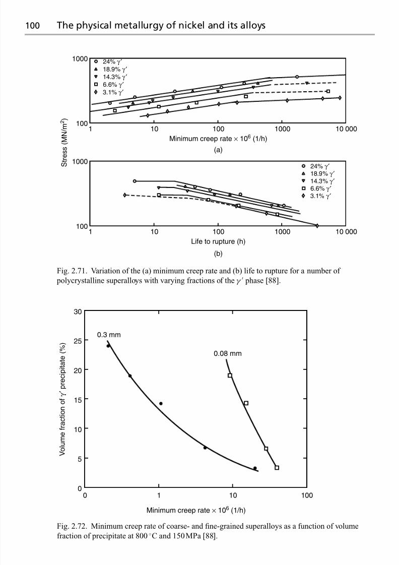
7/18/2019 The Superalloys Fundamentals and Applications
http://slidepdf.com/reader/full/the-superalloys-fundamentals-and-applications 118/389
100 The physical metallurgy of nickel and its alloys
1000
1 10 100 1000 10 000
24% γ ′18.9% γ ′14.3% γ ′6.6% γ ′
3.1% γ ′
24% γ ′18.9% γ ′14.3% γ ′6.6% γ ′
3.1% γ ′
(a)
(b)
Minimum creep rate × 106 (1 /h)
100
100
1000
1 10 100 1000 10 000
Life to rupture (h)
S t r e s s ( M N / m 2 )
Fig. 2.71. Variation of the (a) minimum creep rate and (b) life to rupture for a number of
polycrystalline superalloys with varying fractions of the γ phase [88].
0 1 10 100
0
5
10
15
20
25
30
0.3 mm
0.08 mm
Minimum creep rate × 106 (1 /h)
V o l u m e f r a c t i o n o f γ
′ p r e c i p i t a t e ( % )
Fig. 2.72. Minimum creep rate of coarse- and fine-grained superalloys as a function of volume
fraction of precipitate at 800 ◦C and 150MPa [88].

7/18/2019 The Superalloys Fundamentals and Applications
http://slidepdf.com/reader/full/the-superalloys-fundamentals-and-applications 119/389
2.5 Summary 101
Table 2.1. The nominal compositions of the Nimonic series of superalloys, in
weight%
Alloy C Cr Ti Al Co Mo Ni
Nimonic 80A 0.07 19.5 2.4 1.4 — — Bal Nimonic 90 0.08 19.5 2.4 1.4 17 — Bal Nimonic 105 0.13 15.0 4.7 1.3 20 5.0 Bal Nimonic 115 0.15 14.5 3.8 5.0 13 3.3 Bal
form of creep damage in polycrystalline nickel alloys is creep cavitation at the γ –grain
boundaries – this becomes less influential as the grain size increases. This effect is exploited
in the single-crystal superalloys; a full discussion of these is presented in Chapter 3, butat this point it should be acknowledged that the single-crystal superalloys behave under
creep conditions in a very different manner from the polycrystalline alloys from which they
were derived. The differences have been summarised succinctly by McLean [89]. First, the
shape of the creep curve of the single-crystal superalloys is different; over wide ranges of
temperature and applied stress there is no substantial secondary or ‘steady-state’ regime,
but instead, over most of the life, the creep rate increases progressively. However, there is
no obvious sign of the cavitation or cracking which causes tertiary creep in simple metals.
Second, the values of the stress exponent, n, and creep activation energy, Q, derived by
fitting the power law of Equation (1.7) to the creep data are typically greater than 8 and about three times the activation energy for self-diffusion of nickel – these findings imply a
breakdown of power-law creep so that other theories are required. These are presented in
Chapter 3. Third, single-crystal superalloys show a progressive increase in the dislocation
density over all of the creep life; there isno evidence that a steady-state is reached, and indeed
the dislocation densities are very low compared with simple metals. Finally, pre-straining
of single-crystal superalloys weakens them in creep. This is in contrast to the simple metals,
which are strengthened if the material is pre-conditioned in this way. This characteristic
is, however, not limited to the single-crystal superalloys – the polycrystalline superalloys,
such as Nimonic 80A, which possess a significant fraction of γ behave in this way too
[90]; see Figure 2.73. Despite the fact that grain-boundary cavitation is the predominant
form of creep damage near the end of life, this confirms that it is the mobile dislocation
density which controls the evolution of creep strain at short times, even in polycrystalline
superalloys.
2.5 Summary
The physical metallurgy of nickel and its alloys has been reviewed. The high-temperature
properties depend crucially upon the combination of alloying elements chosen, since these
promote precipitation hardening (most often by the ordered phaseγ , but also byγ in iron-
rich alloys) and solid-solution strengthening. Additions of Al, Ti and Ta – the importantγ
forming elements – are particularly critical if adequate strength levels are to be achieved.

7/18/2019 The Superalloys Fundamentals and Applications
http://slidepdf.com/reader/full/the-superalloys-fundamentals-and-applications 120/389
102 The physical metallurgy of nickel and its alloys
0
10
20
30
40
500 1000
Creep time (h)
E f f e c t i v e c r e e p s t r a i n ε ( % )
−
15% prior plasticdeformation
Zero prior plasticdeformation
Fig. 2.73. Torsional creep data determined from hollow specimens of the Nimonic 80A
polycrystalline superalloy, tested at 750 ◦C and an effective stress of 234 MPa [90]. The dashed linecorresponds to a specimen which had been pre-strained plastically to 15% prior to creep testing.
Note that creep softening is induced by the prior deformation.
The γ matrix phase possesses a cube–cube orientation relationship with theγ precipitate
phase which forms from it; these display the face-centred cubic (FCC) and L12 crystal
structures, respectively. Provided that the elemental partitioning betweenγ and γ is optimal
such that the γ and γ lattice parameters are balanced, the lattice misfit is small, the γ/γ
interfaces arecoherent andtheelastic strainenergy isminimised. Otherphasesof importance
are the carbides MC, M23C6 and M6C, which are rich in Cr, Hf, Mo, Ti, Ta and W, and
the topologically close-packed (TCP) phases μ, P, σ and R, which contain substantial
concentrations of Cr, Mo and Re.
Defects are present – despite the crystalline nature of the phases – which control the
mechanical properties exhibited. These are of various types: point defects such as vacan-
cies; line defects such as dislocations (usually in dissociated form); and planar defects such
as stacking faults. The stacking fault energy of nickel is one of the largest of all FCC
metals at 250 mJ/m2, so that partial dislocations in unalloyed γ are closely spaced. Dissoci-
ation is promoted by alloying additions, which decrease the stacking fault energy such thatcreep processes are hindered. The activation energy for solute–vacancy exchange depends
strongly upon the solute species, with Re possessing a value (in excess of 160 kJ/mol)
larger than for all others in the d block of transition metals; thus, Re is expected to retard
diffusion-controlled processes in nickel alloys. Owing to the ordered structure, defects inγ
are complex. The anti-phase boundary (APB) is one type of planar defect which separates

7/18/2019 The Superalloys Fundamentals and Applications
http://slidepdf.com/reader/full/the-superalloys-fundamentals-and-applications 121/389
The anisotropic elasticity displayed by nickel 103
otherwise perfect crystals displaced by a/2101, which is no longer a lattice vector; the as-
sociated APB energy is strongly anisotropic, being highest on the{110} plane and lowest on
{001}. Intrinsic, extrinsic andcomplex stacking faults havealso been identified. Theenergies
of these planar defects control the mechanism of dislocation dissociation in theγ phase.
Since a a/2110{111} dislocation travelling in γ cannot enter the γ phase without an
APB forming, cutting of the γ/γ structure requires pairs of them; this is the origin of a
substantial precipitation-hardening effect known as order strengthening, which is relevant to
static, tensileproperties. A pairof dislocations (each oneofwhich isknown asa superpartial)
may be either weakly or strongly coupled, depending upon whether their spacing is large or
small in comparison with theγ particle diameter. Cutting by the weak-coupling mechanism
is applicable when the γ particles are in the under-aged condition, but the strong-coupling
oneis appropriate for over-aged structures. Analysis indicates that the degree of hardening is
approximately proportional to the square root of the particle radius,r , for the weak-couplingmechanism and inversely proportional tor for strong coupling; hardening is maximised for
a γ particle size at the transition between the two. For γ/γ alloys, the yield stress does not
decrease strongly as the temperature increases, provided that one stays below about 700◦C;
this arises because of the anomalous yielding effect displayed by the γ phase. The cause
of this is the cross-slip of segments of the γ superpartials from {111} to {001}, promoted
by the applied stress, the anisotropy of the APB energy and a further contribution arising
from elastic anisotropy.
The creep behaviour displayed by nickel and its alloys depends strongly upon the met-
allurgical structure, i.e. the grain size, γ , particle size and the concentrations of alloying
additions. For polycrystalline nickel, a fifth-power-law dependence of the applied stress for
the steady-state ‘secondary’ regime is found in common with other pure metals; this can be
rationalised by balancing dislocation annihilation and multiplication processes (consistent
with the ‘recovery-controlled’ model of creep deformation) provided that the sub-structure
is assumed to coarsen with the cube root of time. Alloying additions have a strong strength-
ening effect on the creep of polycrystalline nickel, with strengthening being most potent
when the atomic size misfit of solute and solvent is large; a distinction is made between
‘Class I’ behaviour, leading to a linear viscous motion of dislocations and a power-law stressdependence of three, and ‘Class II’ behaviour, with a dependence of five, which is analogous
to the pure metals. Analysis indicates that most important alloying additions such as Fe,
Co, Cr, W, Mo, Re and Ru promote Class II behaviour. The γ phase fraction is found to
have a profound influence on creep life, with the potency being greatest when the grain size
is large. This effect occurs because the prominent form of creep damage in polycrystalline
nickel alloys is creep cavitation at γ –grain boundaries, which becomes less influential as
the grain size increases. This effect is exploited in the single-crystal superalloys, which are
the topic of the Chapter 3.
Appendix. The anisotropic elasticity displayed by nickel
Nickel is elastically anisotropic when in single-crystal form. Hence the stiffness – a measure
of the stress necessary to maintain a given strain – is dependent upon the crystallographic

7/18/2019 The Superalloys Fundamentals and Applications
http://slidepdf.com/reader/full/the-superalloys-fundamentals-and-applications 122/389
104 Appendix
Fig. 2.74. Schematic illustration of the equiaxed, columnar and single-crystal structures used for turbine blade aerofoils.
orientation relative to the loading configuration. Consequently, specimens machined at
randomfrom a large singlecrystalwill display differentelastic properties. As turbineblading
is often used in single-crystal or columnar-grained (100-textured) form,see Figure 2.74, it
is important to consider this effect. Moreover, the elastic anisotropy influences the cross-slip
of dislocations, particularly in γ .
A treatment of the elastic anisotropy of nickel requires an acknowledgement that thequantity relating the stress,σ , and strain, , both second-rank tensors, will then be a fourth-
rank tensor [91]. Consider a cubic single crystal with orthogonal axes 1, 2, 3 lying along the
[100], [010] and [001] directions, respectively. The elastic properties are then completely
defined by three elastic stiffness constants C 11, C 12 and C 44, such that
σ 11 = C 1111 + C 1222 + C 1233
σ 22 = C 1211 + C 1122 + C 1233
σ 33 = C 1211 + C 1222 + C 1133
σ 23 = C 44(23 + 32) = 2C 4423
σ 31 = C 44(31 + 13) = 2C 4431
σ 12 = C 44(12 + 21) = 2C 4412 (A1)
where use has been made of the reduced notation of Nye [91]. Note that the cubic symmetry
reduces the number of constants in C i j to three, from the 21 required for a triclinic crystal.
Then C 11 = C 22 = C 33, C 44 = C 55 = C 66 and C 12 = C 13 = C 23; furthermore, the terms
C 14, C 15, C 16, C 24, C 25, C 26, C 34, C 35, C 36, C 45, C 46, C 56 are equal to zero.An alternative representation is via the compliance constants S 11, S 12 and S 44, such that
11 = S 11σ 11 + S 12σ 22 + S 12σ 33
22 = S 12σ 11 + S 11σ 22 + S 12σ 33
33 = S 12σ 11 + S 12σ 22 + S 11σ 33

7/18/2019 The Superalloys Fundamentals and Applications
http://slidepdf.com/reader/full/the-superalloys-fundamentals-and-applications 123/389
The anisotropic elasticity displayed by nickel 105
23 =1
2S 44σ 23
31
=
1
2
S 44σ 31
12 =1
2S 44σ 12 (A2)
The stiffness and compliance constants are inter-related. For example, the compliance con-
stants can be evaluated via
S 11 =C 11 + C 12
(C 11 − C 12)(C 11 + 2C 12)S 12 =
C 12
(C 11 − C 12)(C 11 + 2C 12)S 44 = 1/C 44
(A3)
It is instructive to consider the magnitude of the constants, which have been deter-mined by careful measurements on nickel single crystals. For pure nickel at room tem-
perature, typical values are S 11 = 0.799× 10⁻⁵/MPa, S 12 = −0.312× 10⁻⁵/MPa and
S 44 = 0.844× 10⁻⁵/MPa. The stiffness along the 100 crystallographic direction is then
derived by setting σ 22 = σ 33 = 0, so that
E 100 =σ 11
11
= 1
S 11
(A4)
For the pure nickel data, this gives E 100 = 125 GPa. This is much less than the value for polycrystalline nickel, which, in the absence of texture, is expected to be isotropic, since
the many grains average out the elastic properties over the different orientations. In fact,
polycrystalline nickel has an elastic modulus of about 207 GPa, about 66% higher than that
along the 100 direction. For nickel, it turns out that the 100 direction is the least stiff,
and this is true for most other cubic metals.
How does one go about evaluating the elastic modulus at different crystallographic
orientations, for example, along a direction with direction cosinesl 1, l 2, l 3 defined relative
to the 1, 2, 3 axes? To do this it is necessary to recognise that S is a fourth-rank tensor.
Making use of the reduced notation, the new value of S 11, denoted S 11, is given by
S 11 =
⎡⎢⎢⎢⎢⎢⎢⎣
+l 41 S 11 +2l 21l 22 S 12 +2l 21l 23 S 13 +2l 21l 2l 3 S 14 +2l 31l 3 S 15 +2l 31l 2 S 16
+l 42 S 22 +2l 22l 23 S 23 +2l 32l 3 S 24 +2l 1l 22l 3 S 25 +2l 1l 32 S 26
+l 43 S 33 +2l 2l 33 S 34 +2l 1l 33 S 35 +2l 1l 2l 23 S 36
+l 22l 23 S 44 +2l 1l 2l 23 S 45 +2l 1l 22l 3 S 46
+l 21l 23 S 55 +2l 21l 2l 3 S 56
+l 21l 22 S 66
⎤⎥⎥⎥⎥⎥⎥⎦
(A5a)for the general case of a monoclinic crystal. Note that the various 2’s are present due to
the symmetry of S . For a cubic crystal such as Ni, S 11 = S 22 = S 33, S 44 = S 55 = S 66 and
S 12 = S 13 = S 23 with the other terms zero. Hence,
S 11 = S 11
l 41 + l 42 + l 43
+ 2S 12
l 21l 22 + l 21l 23 + l 22l 23
+ S 44
l 21l 22 + l 21l 23 + l 22l 23
(A5b)

7/18/2019 The Superalloys Fundamentals and Applications
http://slidepdf.com/reader/full/the-superalloys-fundamentals-and-applications 124/389
106 Appendix
350
300
250
200
150
100
200 400 600 800 1000 120050
Temperature (K)
⟨111⟩
⟨011⟩
⟨001⟩AM1
Thymonel 8
Y o u n g ' s m o d u l u s ( G P a
)
Fig. 2.75. Variation of the elastic modulus of single-crystal Thymonel and AM1 with
crystallographic orientation and temperature [92].
Making use of the identities l 21 + l 22 + l 23 = 1 and l 41 + l 42 + l 43 = 1− 2(l 21l 22 + l 21l 23 + l 22l 23 ),
the transformation to the new axis is accomplished using
1
E = S 11 = S 11 − 2
S 11 − S 12 −
1
2S 44
l 21l 22 + l 22l 23 + l 23l 21
(A6)
Thus, the degree of anisotropy depends upon the terml 21l 22 + l 22l 23 + l 23l 21
, which has a
minimum value of zero along the cube axes, a maximum value of one-third along111 and
a value of one-quarter along 110. Using the values of S i j for pure nickel, one can show
that the 100 direction is the least stiff,111 the stiffest (about 2.4 times stiffer than100),with
110
between the two limits. The values are E 100
=125 GPa, E 110
=220 GPa and
E 111 = 294 GPa. Single-crystal superalloys display a similar degree of anisotropy; seeFigure 2.75 [92].
What can be said about the resistance to shearing, for example, in the 23 plane, which
has as its normal the solidification direction 100? From the elasticity equations, one can
see that this is largely controlled by the value of S 44; however, the resistance to shearing
does vary with angle in the 23 plane. One can transform S 44 to S 44 using similar methods
used to determine S 11 above; one can show that the rotation through an arbitrary angleθ is
accomplished via
S 44 = S 44 + (2S 11 − 2S 12 − S 44)× 4sin2
θ cos2 θ = S 44 + (2S 11 − 2S 12 − S 44)× sin2
2θ (A7)
Thus, when θ = 0, G is the reciprocal of S 44 and about 119 GPa. When θ = π/4, G is the
reciprocal of S 44 and is about 26 GPa. For isotropic, polycrystalline nickel, the value of G
has been determined to be about 82 GPa, not far from the numerical average of 119 GPa
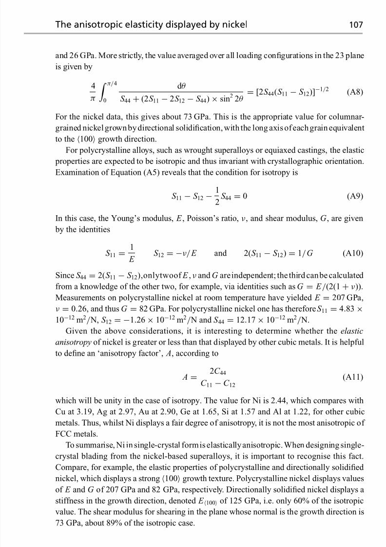
7/18/2019 The Superalloys Fundamentals and Applications
http://slidepdf.com/reader/full/the-superalloys-fundamentals-and-applications 125/389
The anisotropic elasticity displayed by nickel 107
and 26 GPa. More strictly, the value averaged over all loading configurations in the 23 plane
is given by
4
π π/4
0
d θ
S 44 + (2S 11 − 2S 12 − S 44)× sin2 2θ = [2S 44(S 11 − S 12)]−1/2
(A8)
For the nickel data, this gives about 73 GPa. This is the appropriate value for columnar-
grained nickelgrownbydirectional solidification, with the long axis ofeachgrain equivalent
to the 100 growth direction.
For polycrystalline alloys, such as wrought superalloys or equiaxed castings, the elastic
properties are expected to be isotropic and thus invariant with crystallographic orientation.
Examination of Equation (A5) reveals that the condition for isotropy is
S 11 − S 12 − 12
S 44 = 0 (A9)
In this case, the Young’s modulus, E , Poisson’s ratio, ν, and shear modulus, G , are given
by the identities
S 11 =1
E S 12 = −ν/ E and 2(S 11 − S 12) = 1/G (A10)
Since S 44 = 2(S 11 − S 12),onlytwoof E , ν and G areindependent; the third canbe calculated
from a knowledge of the other two, for example, via identities such asG = E /(2(1+ ν)).Measurements on polycrystalline nickel at room temperature have yielded E = 207 GPa,
ν = 0.26, and thus G = 82 GPa. For polycrystalline nickel one has thereforeS 11 = 4.83×10⁻¹² m2/ N, S 12 = −1.26× 10⁻¹² m2/ N and S 44 = 12.17× 10⁻¹² m2/ N.
Given the above considerations, it is interesting to determine whether the elastic
anisotropy of nickel is greater or less than that displayed by other cubic metals. It is helpful
to define an ‘anisotropy factor’, A, according to
A=
2C 44
C 11 − C 12
(A11)
which will be unity in the case of isotropy. The value for Ni is 2.44, which compares with
Cu at 3.19, Ag at 2.97, Au at 2.90, Ge at 1.65, Si at 1.57 and Al at 1.22, for other cubic
metals. Thus, whilst Ni displays a fair degree of anisotropy, it is not the most anisotropic of
FCC metals.
To summarise, Ni in single-crystal formis elasticallyanisotropic.When designing single-
crystal blading from the nickel-based superalloys, it is important to recognise this fact.
Compare, for example, the elastic properties of polycrystalline and directionally solidified
nickel, which displays a strong 100 growth texture. Polycrystalline nickel displays valuesof E and G of 207 GPa and 82 GPa, respectively. Directionally solidified nickel displays a
stiffness in the growth direction, denoted E 100 of 125 GPa, i.e. only 60% of the isotropic
value. The shear modulus for shearing in the plane whose normal is the growth direction is
73 GPa, about 89% of the isotropic case.

7/18/2019 The Superalloys Fundamentals and Applications
http://slidepdf.com/reader/full/the-superalloys-fundamentals-and-applications 126/389
108 Questions
Questions
2.1 Nickel has an atomic weight of 58.71, a number which arises from the relative pro-
portions of isotopes of weights 58, 60, 61, 62 and 64. Why is there little contribution
from the isotopes of weight 59 and 63?
2.2 Nickel exhibits the FCC crystal structure, with a well-defined melting temperature
of 1455 ◦C. But suppose that it was possible to supercool nickel liquid rapidly below
the melting temperature, suppressing the formation of γ . At what approximate tem-
perature might one expect the metastable HCP solid to form? Answer this question
by investigating a binary phase diagram Ni–X, where X is an element from the d
block which displays the HCP crystal structure. Given that the latent heat of melt-
ing of nickel is about 10 J/(mol K), estimate the difference in the Gibbs energy of
the FCC and HCP forms at the temperature of solidification of the metastable HCP
form.Kaufman has carried out pioneering work on the lattice stabilities of the pure
elements. His data for nickel (relative to the ferromagnetic FCC form) are: (i) liquid:
17614− 10.299 T ; (ii) HCP: 1046− 1.255 T ; (iii) BCC: 5564− 1.06 T , where T is
inKelvin and the expressionsgivedata in J/mol. Plotout these expressions asa function
of temperature. Are Kaufman’s data in reasonable agreement with your findings?
2.3 Consider a hypothetical binary phase diagram which displays complete solid solu-
bility at low temperatures and a (solid + liquid) two-phase region below the liquid
phase field. If both phases are ideal, demonstrate that just four parameters are suffi-
cient for the calculation of the phase diagram. Using a spreadsheet, investigate howthe shape and width of the two-phase region depends upon different combinations
of the two parameters S L→φ
1 and S L→φ
2 . Give a physical explanation for your
findings.
In the Ni–Cr binary system, the liquid phase shows considerable deviation from
ideality. For example, the Gibbs free energy of mixing at xCr = 0.5 is −13.1 kJ/mol
at 1873 K. Using this information, modify the spreadsheet developed to describe the
thermodynamic equilibria displayed by the Ni–Cr phase diagram. Demonstrate that
the phase diagram is reproduced reasonably accurately.
2.4 Saunders has developed a thermodynamic model for theγ /γ equilibria in the binary
Ni–Al system. The molar Gibbs energy, G ϕm{T }, of each phase, ϕ, as a function of
temperature (T ) is represented by
G ϕm{T } −
i
xϕ
i0 H i {298.15 K } = G ref ,ϕ
m + G ent,ϕm + G E,ϕm
where xϕ
i is the mole fraction of component i in phase ϕ and 0 H i {298.15 K } is the
molar enthalpy of i in its standard state at 298.15 K. The terms G ref ,ϕm , G ent,ϕ
m and G E,ϕm
are the reference, configurational entropy and excess contributions to the molar Gibbsenergy. The disordered γ phase is modelled with a single sub-lattice, with
G γ m = xγ
Al
G
γ
Al{T } − 0 H Al{298.15 K }+ xγ
Ni
G
γ
Ni{T } − 0 H Ni{298.15 K }
G ent,γ m = RT
xγ
Al ln xγ
Al
+ x
γ
Ni ln xγ
Ni

7/18/2019 The Superalloys Fundamentals and Applications
http://slidepdf.com/reader/full/the-superalloys-fundamentals-and-applications 127/389
Questions 109
and
G E,γ m = xγ
Al xγ
Ni Lγ
Al, Ni
where the term L
γ
Al, Ni is an interaction parameter. The Ni3Al phase can be modelled as a point compound, where
G γ
m = G γ
Ni:Al
such that there are no entropy and excess contributions.
Given the thermodynamic data given below, plot out the variation of G γ m and G
γ m
with temperature. Using graphical means or otherwise, determine the position of the
γ/(γ + γ ) phase diagram as a function of temperature. Furthermore, estimate the
ordering energy as a function of temperature.
The following thermodynamic data are in J/mol:
G γ
Al = −11278.378+ 188.684 153 T − 31.748 192 T ln T − 1.231× 1028T −9;
G γ
Ni = −5179.159+ 117.854 T − 22.096 T ln T − 0.0048407 T 2
Lγ
Al, Ni = −168 750+ 16 T + 30600 xγ
Al − xγ
Ni
+ 41 700 xγ
Al − xγ
Ni
2
G γ
Ni:Al = 0.75 G γ
Ni − 40 000+ 3 T + 0.25 G γ
Al
2.5 Using published ternary phase diagrams for the Ni–Al–Cr system, investigate the
effect on the solid-state equilibria of increasing the Cr content from zero to 25 at%, in
a series of alloys containing (i) a constant Al content of 15 at% and (b) a constant Ni
content of 75 at%. Use Thermo-Calc to help validate your conclusions.
2.6 Examination of Ni–Al–X ternary phase diagrams, where X is a ternary addition such
as Ti, Nb, Pt, Re, etc., indicates that the γ phase field is often parallel to either (i) the
Ni–X axis or alternatively (ii) the Al–X axis. What causes this to happen? Very rarely,
this is not the case: for Cr, for example. Why should such elements not conform this
to this general rule?
2.7 In Figure 2.10 (taken from ref. [8]) the enthalpies of formation of the intermetallic
compounds in the Ni–Al system are compared with the enthalpy of mixing of the FCC
phase. Since the data correspond to the low temperature of 25◦C, it is claimed that
the entropy contribution is small, so that H f behaves like G f .
Using the Thermo-Calc software, investigate whether this is a good assumption.
Estimate a value of (i) the ordering energy of β –NiAl and (ii) the enthalpy of formation
at 25 ◦C, measured with respect to the disordered BCC phase.
It is found that, of all the intermetallic phases in the Ni–Al system, the ordering
energy is largest for β –NiAl. Remembering that this displays the CsCl crystal structure,
give a physical explanation for this.2.8 The lattice parameters of the γ and γ phases in the superalloys depend upon the alloy
chemistry. However, the lattice parameter of γ is, in general, slightly more sensitive
to solute additions than γ ; see Figure 2.18. Give a rationale for this observation.
2.9 The atom probe can be used to build up a ladder diagram in which the total number of
atoms detected is plotted against the total number of atoms detected. For a specimen

7/18/2019 The Superalloys Fundamentals and Applications
http://slidepdf.com/reader/full/the-superalloys-fundamentals-and-applications 128/389
110 Questions
of pure Ni3Al, explain the features of the curve which are observed, and estimate the
slopes of the different regimes.
2.10 The lattice parameter of the Ni3Al phase at room temperature is 0.357 00 nm. Given
that it displays the L12 structure, estimate the atomic radii of Ni and Al in this
compound. Is there any evidence that the bonding is directional in nature? How does
the value for Ni compare with that of pure Ni, which has a lattice parameter of
0.35167nm?
2.11 Investigate how the radius of the transition group metals varies as one crosses any
one period of the periodic table. Repeat this exercise so that you have information
for the first three series. What patterns emerge? And do the γ -forming elements
display significantly different values from the elements which form solid solutions
with γ –nickel?
2.12 In the intermetallic compounds γ –Ni3Al and β –NiAl, various sorts of point defectsare possible. Distinguish between the four most common of these.
2.13 Whilst both Frenkel and Schottky defects can arise in compounds such asβ –NiAl,
only one of these can occur in a pure elemental crystal such as Ni. Identify which of
these defects may form in pure Ni, and explain why this is not possible for the other
defect.
2.14 Bradley and Taylor [41] made measurements of the lattice spacing and density of
the NiAl intermetallic compound at compositions at and around the point of exact
stoichiometry (Figure 2.76). Use their data to prove conclusively that (i) on the Ni-
rich side, the excess Ni atoms are accommodated as anti-site defects, and (ii) on theAl-rich side, the excess Al atoms are not accommodated as anti-site defects and that
there must be a significant proportion of constitutional vacancies present. What is
the fraction of constitutional vacancies present for an alloy on the phase boundary
on the Al-rich side?
2.15 Theoretical expressions for the self-diffusion of pure metal indicate that the rate is
proportional to Z , the number of neighbours nearest to any given atom. For nickel,
which possesses the cubic F structure, determine Z and the corresponding lattice
vector. How would your answers differ if nickel exhibited (i) the cubic P and (ii) the
cubic I lattices?
2.16 Explain why the tracer diffusion coefficient of Al in theγ phase (which has the L12
structure) is considerably smaller than that of Ni.
2.17 Comparison of the rates of interdiffusion of the transition group metals (the so-
lutes) with nickel (the solvent) indicates that (i) the interdiffusion rate increases
with increasing misfit strain between solvent and solute and (ii) the activation en-
ergy for interdiffusion decreases with increasing misfit strain. Why might these
observations be contrary to expectation? How might this apparent anomaly be
rationalised?2.18 The interdiffusion coefficient of nickel with aluminium in theβ –NiAl intermetallic
compound is strongly dependent upon concentration. The minimum value is near the
point of 50:50 stoichiometry, but not quite so. Why is this?
2.19 Self-diffusion in nickel is mediated by the exchange of atoms and vacancies on the
lattice – so-called ‘vacancy-assisted diffusion’. The micromechanism involves the

7/18/2019 The Superalloys Fundamentals and Applications
http://slidepdf.com/reader/full/the-superalloys-fundamentals-and-applications 129/389
Questions 111
44 46 48 50 52 54 56 58 60 62
At %Ni
2854
2858
2866
2862
2870
2874
2878
2882
R e l a t i v e l a t t i c e p a r a m e t e r
6.6
6.5
6.4
6.36.2
6.1
6.0
5.9
5.8
5.7
5.6
5.5
5.4
5.3
Two-phaseTwo-phase
D
e n s i t y ( g / c m 3 )
Fig. 2.76. Variation of the density and relative lattice parameter of NiAl around the point of
stoichiometry [41].
movement of an atom by a distance a/√
2 in the direction 110. Show that the
size of the diffusion window is (√
3− 1) D Ni at the saddle point, where D Ni is the
hard-sphere diameter of a Ni atom.
2.20 A rod of Ni is heated to its melting point, at which the concentration of vacancies is
3.3× 10⁻⁵ per atomic site. The rod is then quenched so that all vacancies generated
at themelting point are trapped on the lattice. Upon annealingat a higher temperature,
the rod is observed to shrink. Why? If the total contraction is 5.1× 10⁻⁶, what change
in lattice parameter should be observed during the annealing process?
2.21 Show that it is favourable for a perfect dislocation with Burgers vector a2[110] slipping
on (111) in a cubic close-packed (CCP) metal such as nickel to dissociate into two
partial dislocations. Give the Burgers vectors of the partial dislocations. What factors
determine their equilibrium separation?Cobalt is often added to the nickel-based superalloys. Explain why the addi-
tion of cobalt is beneficial. Why might the effects of other elements be more
potent?
2.22 Show that, on the basis of dislocation mechanics and isotropic elasticity, a per-
fect screw dislocation gliding in nickel will dissociate into two Shockley partial

7/18/2019 The Superalloys Fundamentals and Applications
http://slidepdf.com/reader/full/the-superalloys-fundamentals-and-applications 130/389
112 Questions
dislocations separated by a distance Ga 2
48πγ
2−3ν1−ν
, where G is the shear modulus, ν is
Poisson’s ratio and a is the lattice parameter.
The following information is provided. The shear stress field a distancer from the
centre of a perfect screw dislocation of Burgers vector b is Gb/(2πr ). The associated
elastic strain energy of this dislocation integrates to Gb2 ln{ R/r 0}/(4π), where r 0 is
the core radius and R is the upper limit of integration.
2.23 The anti-phase boundary (APB) energy of the L12 structure is proportional to the
ordering parameter, , which is equal to NiAl − 12( NiNi +AlAl). By sketching
sections of the (100), (011) and (111) planes, and noting that the lattices across
the APB are related by a 1/2[011] vector, convince yourself (following Flinn) that
(i) the energies of APBs on the (011) and (111) planes are in the ratio√
3 :√
2, and
(ii) the energy of an APB on the (100) plane is likely to be nearly zero. Consider only
the nearest-neighbour interactions.2.24 Stobbs has made measurements of the APB energies in the disc alloy RR1000, using
weak-beam TEMmicroscopy to image dislocation pairings in theγ phase. His figure
for the {100} plane, 200 mJ/m2, is not very different from that in the {111} plane, at
300mJ/m2. This is despite Flinn’s analysis (see Question 2.23), which indicates that
the {100} APB should be close to zero. How can this apparent anomaly be resolved?
2.25 The Nb-rich compound Ni3 Nb, known as γ , confers precipitation strengthening to
iron-rich superalloys such as IN718. It possesses a body-centred tetragonal crystal
structure, which is related to that of γ by a somewhat different ordering scheme (see
Figure 2.21) and a doubling of the lattice parameter in one of the cube directions.
Draw out a plan of a pseudo-close-packed plane of theγ phase, and identify the
magnitudes of possible Burgers vectors. Hence convince yourself that in only one of
three directions will order be restored as a result of the movement of two a/2110matrix dislocations cutting through γ , and that, in the other two directions, four
such dislocations are required. Thus explain why γ -strengthened alloys possesses
extremely high strength levels at elevated temperatures.
2.26 Oblak, Paulonis and Duvall [93] studied the flow characteristics of the iron–nickel
superalloy IN718, in single-crystal form, with the tensile axis along 001. Whentested at 300 ◦C, the yield stress was 300 MPa; however, if the specimens were first
aged at 790 ◦C for 5 h, the yield stress was altered by+25% and −6% for tensile and
compressive loads, respectively. Give an explanation for these findings.
2.27 Each of the alloying elements present in a superalloy is expected to make a contribu-
tion to the level of solid-solution strengthening, such that the yield stress is increased
by an increment σ . To sum the contributions from the concentrations, ci , of each
element i , it has been suggested that one uses
σ =
i
k 2i ci
1/2
Tensile testing at room temperature indicates that suitable values for thek i ’s are Al=225, Ti= 775, Zr = 2359, Hf = 1401, Cr = 337, Mo= 1015, W= 977, Mn= 448,
Fe= 153 and Co= 39, where the units are in MPa× at.fraction−1/2.

7/18/2019 The Superalloys Fundamentals and Applications
http://slidepdf.com/reader/full/the-superalloys-fundamentals-and-applications 131/389
Questions 113
Use this relationship and the data provided to quantify, for the single-crystal
superalloy SRR99, the relative contributions of the different elements to the solid-
strengthening levels to be expected in this alloy.
2.28 In order to evaluate the temperature dependence of the shear yield stress, τ y, of a
solid-solution-strengthened alloy, one can appeal to the trough model, which predicts
T τ y
G
1/2
= K 1 − K 2τ y
where T is temperature and G is the shear modulus. The terms K 1 and K 2 are
constants, which are in the range 5.7 to 27 K ( K 1) and 0.22 to 0.26 K /MPa ( K 2).
Using the expression, the data provided and a suitable estimate for G , investigate
how the shear yield stress, τ y, is expected to vary as a function of temperature. What
is the effect of incorporating a temperature dependence intoG ?
2.29 The expression derived in Section 2.3 for the strengthening arising from strongly
coupled dislocation pairs is dependent upon the function{ x}. For spherical particles
of radius r , { x} is given by 2(2r x − x2)1/2; the results in a r −1/2 dependence for the
strengthening, when r is large.
Suppose instead one considers cuboidal particles. What then is the appropriate
shape of the cross-section, if the slip plane is{111}? Derive an expression for { x} for
this case. Is the r −1/2 dependence preserved? If not, is the dependence onr stronger
or weaker than for spherical particles?
2.30 In nominally pure nickel in the annealed state, the movement of dislocations during plastic deformation is not limited by the Peierls–Nabarro stress, which is of very small
magnitude (in common with all FCC materials). Evidence from this comes from
TEM studies, which indicate that the dislocations are wavy with little evidence of
pinning being displayed. This being the case, what phenomenon controls dislocation
movement? How would the situation be different if nickel were to be heavily worked?
2.31 The shear strain rate, γ , arising due to low-temperature plasticity has been modelled
in a phenomenological sense by Kocks, Argon and Ashby according to
γ = γ 0
σ s
μ
2
exp− F
kT
1−
σ s/τ p pq
where σ s is the deviatoric stress, μ is the shear modulus, τ 0 is the shear stress at 0 K
and F is an activation energy required either for (i) overcoming discrete obstacles
or else (ii) formation of an isolated pair of kinks. The other terms, γ 0, p and q, are
constants; theory suggests that 0≤ p ≤ 1 and 1 ≤ q ≤ 2, with γ 0 about 106/s.
Make a fit to theflow stress–temperaturedata fornickel(see Figure 2.52), including
data down to cryogenic temperatures. Do your fitted parameters reveal much about the
factors controlling slip? What is revealed about the strain-rate sensitivity? Convinceyourself that the strain-rate sensitivity is low compared with, for example, that seen
during power-law creep.
2.32 The elastic modulus of nickel is highly anisotropic; the Young’s moduli along111,110 and 100 at ambient temperature are in the ratio 2.80:1.71:1. By determining
the interplanar spacings in the cubic close-packed (CCP) crystal structure, rationalise

7/18/2019 The Superalloys Fundamentals and Applications
http://slidepdf.com/reader/full/the-superalloys-fundamentals-and-applications 132/389
114 References
the observation that the 111 and 100 directions are the most and least stiff,
respectively.
2.33 Thevariation of theYoung’s modulus around the100 pole is of profound importance
in the design of turbine blading, since resonance can cause high-cycle fatigue failure.
Using the expressions given in the Appendix to this chapter, investigate how the
Young’s modulus varies within 20◦ of 100. For CMSX-4 blading at 700◦C, take
E 100 = 104 GPa, E 110 = 190 GPa and E 111 = 262GPa.
2.34 In the context of the elasticity of monocrystalline nickel, prove the following identi-
ties:
S 11 =C 11 + C 12
(C 11 − C 12)(C 11 + 2C 12)S 12 =
C 12
(C 11 − C 12)(C 11 + 2C 12)S 44 = 1/C 44
where the S i j
and C i j
are components of the compliance and stiffness matrices,
respectively.
2.35 In Section 2.4, the σ 5 stress dependence of steady-state creep in pure nickel was
justified on the basis that time scales with the third power of the characteristic length
of the dislocation sub-structureλ. But suppose instead that a fifth power law (corre-
sponding to coarsening of the the sub-grains by pipe diffusion) applies. Demonstrate
that the exponent in the steady-state creep law is then equal to 7.
2.36 In the climb-plus-glide creep model of Weertman, the total time, t total, that a disloca-
tion spends deforming is partitioned into glide and climb components, such that
t total = t glide + t climb
By (i) dividing through by the productρbL, where ρ is the dislocation density, b is
the Burgers vector and L is the average distance that a dislocation moves parallel to
the slip plane, and (ii) defining the total, glide and climb components of the strain
rate in an appropriate way, demonstrate that
1
total
= 1
glide
+ 1
climb
so that one has a sequential process for the net strain rate.
2.37 Creep-rupture data for polycrystalline, nominally pure nickel are plotted on Fig-
ure 2.66. Use these data to plot a line for Ni on the Larson–Miller plot of Figure 1.16.
Hence show that many intermetallics are superior to Ni in creep, but that they cannot
compete at present with the single-crystal superalloys.
References[1] C. T. Sims, N. S. Stoloff and W. C. Hagel, eds, Superalloys II: High Temperature
Materials for Aerospace and Industrial Power (New York: John Wiley and Sons,
1987).
[2] M. Durand-Charre, The Microstructure of Superalloys (Amsterdam: Gordon &
Breach Science Publishers, 1997).

7/18/2019 The Superalloys Fundamentals and Applications
http://slidepdf.com/reader/full/the-superalloys-fundamentals-and-applications 133/389
References 115
[3] P. Nash, ed., Phase Diagrams of Binary Nickel Alloys (Materials Park, OH: ASM
International, 1991).
[4] A.T. Dinsdale, SGTE data for pure elements, Calphad , 15 (1991), 317–425.
[5] L. Kaufman and H. Bernstein, Computer Calculation of Phase Diagrams (New
York: Academic Press, 1970).
[6] J. O. Andersson, T. Helander, L. Hoglund, P. F. Shi and B. Sundman, Thermo-Calc
and DICTRA: computational tools for materials science, Calphad , 26 (2001),
273–312.
[7] N. Saunders, Phase diagram calculations for high-temperature materials,
Philosophical Transactions of the Royal Society of London A, 351 (1995),
543–561.
[8] K. J. Blobaum, D. Van Heerden, A. J. Gavens and T. P. Weihs, Al/Ni formation
reactions: characterisation of the metastable Al9 Ni2 phase and analysis of itsformation, Acta Materialia, 51 (2003), 3871–3884.
[9] S. Ochiai, Y. Oya and T. Suzuki, Alloying behaviour of Ni3Al, Acta Metallurgica,
32 (1984), 289–298.
[10] K. Hono, Private communication, The National Institute of Materials Science,
Tsukuba Science City, Japan (2003).
[11] R. W. Cahn, P. A. Siemers and J. E. Geiger, The order-disorder transformation in
Ni3Al and Ni3Al− Fe alloys: 1. Determination of the transition temperatures and
their relation to ductility, Acta Metallurgica, 35 (1987), 2737–2751.
[12] F. J. Bremer, M. Beyss and H. Wenzl, The order-disorder transition of theintermetallic phase Ni3Al, Physica Status Solidi, 110A (1988), 77–82.
[13] S. V. Prikhodko and A. J. Ardell, Coarsening of gamma prime in Ni-Al alloys aged
under uniaxial compression: III. Characterisation of the morphology,Acta
Materialia, 51 (2003), 5021–5036.
[14] R. A. Ricks, A. J. Porter and R. C. Ecob, The growth of gamma prime precipitates
in nickel-base superalloys, Acta Metallurgica, 31 (1983), 43–53.
[15] E. E. Brown and D. R. Muzyka, Nickel-iron alloys, in C. T. Sins, N. S. Stoloff and
W. C. Hagel, eds, Superalloys II: High Temperature Materials for Aerospace and
Industrial Power (New York: John Wiley and Sons, 1987), pp. 165–188.
[16] J. W. Brooks and P. J. Bridges, Metallurgical stability of Inconel 718, in D. N. Duhl,
G. Maurer, S. Antolovich, C. Lund and S. Reichman, eds, Superalloys 1988
(Warrendale, PA: The Metallurgical Society, 1988), pp. 33–42.
[17] R. Cozar and A. Pineau, Morphology of gamma prime and gamma double prime
precipitates and thermal stability of Inconel 718 type alloys,Metallurgical
Transactions, 4 (1973), 47–59.
[18] R. C. Reed, M. P. Jackson and Y. S. Na, Characterisation and modelling of the
precipitation of the sigma phase in Udimet 720 and Udimet 720Li,Metallurgical and Materials Transactions, 30A (1999), 521–533.
[19] A. K. Sinha, Topologically close-packed structures of transition metal alloys,
Progress in Materials Science, 15 (1972), 79–185.
[20] S. Tin, T. M. Pollock and W. T. King, Carbon additions and grain boundary
formation in high refractory nickel-base single crystal superalloys, in T. M. Pollock,

7/18/2019 The Superalloys Fundamentals and Applications
http://slidepdf.com/reader/full/the-superalloys-fundamentals-and-applications 134/389
116 References
R. D. Kissinger, R. R. Bowman et al., eds, Superalloys 2000 (Warrendale, PA: The
Minerals, Metals and Materials Society (TMS), 2000), pp. 201–210.
[21] Q. Z. Chen and D. M. Knowles, The microstructures of base/modified RR2072 SX
superalloys and their effects on creep properties at elevated temperatures,Acta
Materialia, 50 (2002), 1095–1112.
[22] A. Kelly, G. W. Groves and P. Kidd, Crystallography and Crystal Defects, revised
edn (Chichester, UK: John Wiley & Sons, 2000).
[23] F. A. Mohamed and T. G. Langdon, The transition from dislocation climb to
viscous glide in creep of solid solution alloys,Acta Metallurgica, 30 (1974),
779–788.
[24] P. C. J. Gallagher, The influence of alloying, temperature and related effects on the
stacking fault energy, Metallurgical Transactions, 1 (1970), 2429–2461.
[25] L. Delehouzee and A. Deruyttere, The stacking fault density in solid solutions based on copper, silver, nickel, aluminium and lead,Acta Metallurgica, 15 (1967),
727–734.
[26] W. Wycisk and M. Feller-Kniepmeier, Quenching experiments in high purity Ni,
Journal of Nuclear Materials, 69/70 (1978), 616–619.
[27] R. O. Simmons and R. W. Balluffi, Measurements of equilibrium vacancy
concentrations in aluminum, Physical Review, 117 (1960), 52–61.
[28] B. Jonsson, Assessment of the mobilities of Cr, Fe and Ni in binary FCC Cr-Fe and
Cr-Ni alloys, Scandinavian Journal of Metallurgy, 24 (1995), 21–27.
[29] M. S. A. Karunaratne, P. Carter and R. C. Reed, Interdiffusion in the FCC-A1 phaseof the Ni-Re, Ni-Ta and Ni-W systems between 900 and 1300 deg C,Materials
Science and Engineering , A281 (2000), 229–233.
[30] M. S. A. Karunaratne and R. C. Reed, Interdiffusion of the platinum group
metals in nickel at elevated temperatures, Acta Materialia, 51 (2003),
2905–2919.
[31] C. L. Fu, R. C. Reed, A. Janotti and M. Krcmar, On the diffusion of alloying
elements in the nickel-base superalloys, in K. A. Green, T. M. Pollock, H. Harada,
et al., eds, Superalloys 2004 (Warrendale, PA: The Minerals, Metals and Materials
Society (TMS), 2004), pp. 867–876.
[32] A. Janotti, M. Krcmar, C. L. Fu and R. C. Reed, Solute diffusion in metals: larger
atoms can move faster, Physical Review Letters, 92 (2004), 085901.
[33] P. A. Flinn, Theory of deformation in superlattices,Transactions of the
Metallurgical Society of AIME , 218 (1960), 145–154.
[34] B. H. Kear, A. F. Giamei, J. M. Silcock and R. K. Ham, Slip and climb processes in
gamma prime precipitation hardened nickel-base alloys,Scripta Metallurgica, 2
(1968), 287–294.
[35] B. H. Kear, A. F. Giamei, G. R. Leverant and J. M. Oblak, On intrinsic/extrinsicstacking fault pairs in the L12 lattice, Scripta Metallurgica, 3 (1969), 123–130.
[36] D. P. Pope and S. S. Ezz, Mechanical properties of Ni3Al and nickel-base alloys
with high volume fraction of γ , International Metals Reviews, 29 (1984),
136–167.

7/18/2019 The Superalloys Fundamentals and Applications
http://slidepdf.com/reader/full/the-superalloys-fundamentals-and-applications 135/389
References 117
[37] F. R. N. Nabarro and H. L. de Villiers, The Physics of Creep (London: Taylor and
Francis, 1995).
[38] B. H. Kear and H. G. F. Wilsdorf, Dislocation configurations in plastically
deformed Cu3Au alloys, Transactions of the Metallurgical Society of AIME , 224
(1962), 382–386.
[39] K. Aoki and O. Izumi, Defect structures and long-range order parameters in
off-stoichiometric Ni3Al, Physica Status Solidi, 32A (1975), 657–664.
[40] H. Numakura, N. Kurita and M. Koiwa, On the origin of the anelastic relaxation
effect in Ni3Al, Philosophical Magazine, 79A (1999), 943–953.
[41] A. J. Bradley and A. Taylor, An x-ray analysis of the nickel-aluminium system,
Proceedings of the Royal Society of London, A159 (1937), 56–72.
[42] A. Mourisco, N. Baluc, J. Bonneville and R. Schaller, Mechanical loss spectrum of
Ni3(Al,Ta) single crystals, Materials Science and Engineering , A239-240 (1997),281–286.
[43] B. Reppich, Some new aspects concerning particle hardening mechanisms inγ
precipitating Ni-Base alloys – I Theoretical concept, Acta Metallurgica, 30 (1982),
87–94.
[44] B. Reppich, P. Schepp and G. Wehner, Some new aspects concerning particle
hardening mechanisms in γ precipitating Ni-Base alloys – II Experiments, Acta
Metallurgica, 30 (1982), 95–104.
[45] E. Nembach, K. Suzuki, M. Ichihara and S. Takeuchi, In-situ deformation of the
gamma prime hardened superalloy Nimonic PE16 in high-voltage electronmicroscopes, Philosophical Magazine, 51A (1985), 607–618.
[46] E. Nembach, Particle Strengthening of Metals and Alloys (New York: John Wiley
and Sons, 1997).
[47] T. Kruml, E. Conforto, B. Lo Piccolo, D. Caillard and J. L. Martin, From dislocation
cores to strength and work hardening: a study of binary Ni3Al, Acta Materialia, 50
(2002), 5091–5101.
[48] A. J. Ardell, Precipitation hardening,Metallurgical Transactions, 16A (1985),
2131–2165.
[49] W. Huther and B. Reppich, Interaction of dislocations with coherent, stress-free,
ordered precipitates, Zeitschrift f ¨ ur Metallkunde, 69 (1978), 628–634.
[50] D. Hull and D. J. Bacon, Introduction to Dislocations, 4th edn (Sevenoaks:
Butterworth-Heinemann, 2001).
[51] M. P. Jackson and R. C. Reed, Heat treatment of Udimet 720Li: the effect of
microstructure on properties, Materials Science and Engineering , A259 (1999),
85–97.
[52] B. Reppich, Particle strengthening, in R. W. Cahn, P. Haasen and E. T. Kramer, eds,
Materials Science and Technology, Volume 6: Plastic Deformation and Fracture(Weinham, Germany: VCH, 1993), pp. 311–357.
[53] R. G. Davies and N. S. Stoloff, On the yield stress of aged Ni-Al alloys,
Transactions of the Metallurgical Society of AIME , 233 (1965),
714–719.

7/18/2019 The Superalloys Fundamentals and Applications
http://slidepdf.com/reader/full/the-superalloys-fundamentals-and-applications 136/389
118 References
[54] B. J. Piearcey, B. H. Kear and R. W. Smashey, Correlation of structure with
properties in a directionally solidified nickel-base superalloy,Transactions of the
American Society for Metals, 60 (1967), 634–643.
[55] P. Beardmore, R. G. Davies and T. L. Johnston, On the temperature dependence of
the flow stress of nickel-base alloys, Transactions of the Metallurgical Society of
AIME , 245 (1969), 1537–1545.
[56] M. H. Yoo, On the theory of anomalous yield behaviour of Ni3Al – effect of elastic
anisotropy, Scripta Metallurgica, 20 (1986), 915–920.
[57] B. H. Kear and H. G. F. Wilsdorf, Dislocation configurations in plastically
deformed polycrystalline Cu3Au alloys, Transactions of the Metallallurgical
Society of AIME , 224 (1962), 382–386.
[58] A. E. Staton-Bevan and R. D. Rawlings, The deformation behaviour of single
crystal Ni3(Al,Ti), Physica Status Solidi, 29A (1975), 613–622.[59] P. Veyssiere, Yield stress anomalies in ordered alloys: a review of microstructural
findings and related hypotheses, Materials Science and Engineering , A309–310
(2001), 44–48.
[60] P. Veyssiere and G. Saada, Microscopy and plasticity of the L12 γ phase, in F. R. N.
Nabarro and M. S. Duesbery, eds, Dislocations in Solids, Volume 10: L12 Ordered
Alloys (Amsterdam: Elsevier, 1996), pp. 252–441.
[61] R. A. Mulford and D. P. Pope, The yield stress of Ni3(Al,W), Acta Metallurgica, 21
(1973), 1375–1380.
[62] P. H. Thornton, R. G. Davies and T. L. Johnston, The temperature dependence of the flow stress of the γ phase based upon Ni3Al, Metallurgical Transactions, 1
(1970), 207–218.
[63] S. S. Ezz, D. P. Pope and V. Paidar, The tension compression flow-stress asymmetry
in Ni3(Al, Nb) single crystals, Acta Metallurgica, 30 (1982), 921–926.
[64] D. P. Pope and S. S. Ezz, Mechanical properties of Ni3Al and nickel-base alloys
with high volume fraction of γ , International Metals Reviews, 29 (1984),
136–167.
[65] S. S. Ezz, D. P. Pope and V. Vitek, Asymmetry of plastic-flow in Ni3Ga single
crystals, Acta Metallurgica, 35 (1987), 1879–1885.
[66] D. C. Chrzan and M. J. Mills, Dynamics of dislocation motion in L12 compounds,
in F. R. N. Nabarro and M. S. Duesbery, eds, Dislocations in Solids, Volume 10: L12
Ordered Alloys (Amsterdam: Elsevier, 1996), pp. 187–252.
[67] X. Shi, Doctoral Thesis, University Paris-Nord, France (1995).
[68] P. B. Hirsch, A model of the anomalous yield stress for (111) slip in L12 alloys,
Progress in Materials Science, 36 (1992), 63–88.
[69] W. D. Jenkins, T. G. Digges and C. R. Johnson, Creep of high purity nickel,Journal
of Research of the National Bureau of Standards, 53 (1954), 329–352.[70] A. H. Clauer and B. A. Wilcox, Steady-state creep of dispersion-strengthened
nickel, Metal Science, 1 (1967), 86–90.
[71] H. J. Frost and M. F. Ashby, Deformation-Mechanism Maps: The Plasticity and
Creep of Metals and Ceramics (Oxford: Pergamon Press, 1982).

7/18/2019 The Superalloys Fundamentals and Applications
http://slidepdf.com/reader/full/the-superalloys-fundamentals-and-applications 137/389
References 119
[72] A. K. Mukherjee, J. E. Bird and J. E. Dorn, Experimental correlations for
high-temperature creep, Transactions of the American Society for Metals, 62
(1969), 155–179.
[73] J. P. Poirier, Creep of Crystals: High Temperature Deformation Processes in Metals,
Ceramics and Minerals (Cambridge: Cambridge University Press, 1985).
[74] J. Weertman, Creep of indium, lead and some of their alloys,Transactions of the
Metallurgical Society of AIME , 218 (1960), 207–218.
[75] J. Weertman and J. R. Weertman, Mechanical properties, strongly temperature
dependent, in R. W. Cohn ed., Physical Metallurgy (New York: John Wiley & Sons,
1965), pp. 793–819.
[76] G. S. Daehn, H. Brehm, H. Lee and B-S. Lim, A model for creep based on
microstructural length scale evolution, Materials Science and Engineering , 387
(2004), 576–584.[77] H. Brehm and G. S. Daehn, A framework for modeling creep in pure metals,
Metallurgical and Materials Transactions, 32A (2001), 363–371.
[78] J. J. Gilman, Micromechanics of Flow in Solids (New York: McGraw-Hill, 1969).
[79] J. W. Martin and R. D. Doherty, Stability of Microstructure in Metallic Systems
(Cambridge: Cambridge University Press, 1976).
[80] M. Winning, G. Gottstein and L. S. Shvindlerman, On the mechanisms of grain
boundary migration, Acta Materialia, 50 (2002), 353–363.
[81] R. W. Evans and B. Wilshire, Creep of Metals and Alloys (London: The Institute of
Metals, 1985).[82] J. P. Dennison, R. J. Llewellyn and B. Wilshire, The creep and fracture behaviour of
some dilute nickel alloys at 500 and 600◦C, Journal of the Institute of Metals, 94
(1966), 130–134.
[83] J. P. Dennison, R. J. Llewellyn and B. Wilshire, The creep and fracture properties of
some nickel-chromium alloys at 600◦C, Journal of the Institute of Metals, 95
(1967), 115–118.
[84] O. D. Sherby and P. M. Burke, The mechanical behaviour of crystalline solids at
elevated temperatures, Progress in Materials Science, 13 (1967), 325–390.
[85] C. M. Sellars and A. G. Quarrell, The high temperature creep of gold-nickel alloys,
Journal of the Institute of Metals, 90 (1962), 329–336.
[86] W. R. Cannon and O. D. Sherby, High temperature creep behaviour of class I
and class II solid solution alloys, Metallurgical Transactions, 1 (1970),
1030–1032.
[87] F. A. Mohamed and T. G. Langdon, The transition from dislocation climb to
viscous glide in creep of solid solution alloys,Acta Metallurgica, 22 (1974),
779–788.
[88] T. B. Gibbons and B. E. Hopkins, Creep behaviour and microstructure of Ni-Cr base alloys, Metal Science, 18 (1984), 273–280.
[89] M. McLean, Nickel-based alloys: recent developments for the aero-gas turbine, in
H. M. Flower, ed., High Performance Materials for Aerospace (London: Chapman
& Hall, 1995), pp. 135–154.

7/18/2019 The Superalloys Fundamentals and Applications
http://slidepdf.com/reader/full/the-superalloys-fundamentals-and-applications 138/389
120 References
[90] B. F. Dyson, M. S. Loveday and M. J. Rodgers, Grain boundary cavitation under
various states of applied stress, Proceedings of the Royal Society A, 349 (1976),
245–259.
[91] J. F. Nye, Physical Properties of Crystals: Their Representation by Tensors and
Matrices (Oxford: Clarendon Press, 1957).
[92] P. Caron, D. Cornu, T. Khan and J. M. de Monicault, Development of a hydrogen
resistant superalloy for single crystal blade application in rocket engine turbopumps,
in R. D. Kissinger, D. J. Daye, D. L. Anton et al ., eds, Superalloys 1996 (Warrendale,
PA: The Minerals, Metals and Materials Society (TMS), 1996), pp. 53–60.
[93] J. M. Oblak, D. F. Paulonis and D. S. Duvall, Coherency strengthening in Ni–base
alloys hardened by DO22γ precipitates, Metallurgical Transactions, 5 (1974),
143–153.

7/18/2019 The Superalloys Fundamentals and Applications
http://slidepdf.com/reader/full/the-superalloys-fundamentals-and-applications 139/389
3 Single-crystal superalloys forblade applications
The gas turbine consists of many different pieces of turbomachinery, but the rows of turbine
blading are of the greatest importance since many engine characteristics, for example the
fuel economy and thrust, depend very strongly on the operating conditions which can be withstood by them. Thus very arduous temperatures and stresses are experienced by
the materials employed, which are pushed near to the limits of their capability. This is
particularly the case for the high-pressure blades, which are located nearest to the hot gases
emerging from the combustion chamber. Their function is to extract work from the gas
stream and to convert it to mechanical energy in the form of a rotating shaft, which drives
the high-pressure compressor.
A consideration of the operating conditions experienced by the high-pressure turbine
blades in a large civil turbofan engine, such as the Rolls-Royce Trent 800 or General
Electric GE90, confirms this point. The temperature of the gas stream is about 1750 K,which is above the melting temperature of the superalloys from which the blades are made.
The high-pressure shaft develops a power of about 50 MW – hence, with about 100 blades,
each extracts about 500 kW, which is sufficient to satisfy the electricity requirement of about
500 homes. Each row of blades is expected to last at least 3 years, assuming they operate
at 9 h/day. This is equivalent to about 5 million miles of flight, or ∼500 circumferences of
the world. The blades rotate at an angular speed, ω, of more than 10 000 revolutions per
minute, so that the tip velocity is greater than 1200 km/h. The stresses experienced by the
blading, which are largely centrifugal in nature due to the significant rotational speeds, are
considerable; if the blade cross-section is assumed to be uniform, the stress, σ , at the blade
root is approximately given by
σ = r tip
r root
ρω2r d r = ρω2
2
r 2tip − r 2root
where ρ is the blade density. The radial positions of the blade tip and root are given by
r tip and r root, respectively. Taking ρ = 9000 kg/m3, the blade length as 10cm and the mean
blade radius to be 0.5 m, the stress at the blade root is given by
σ = 9000 × (100 × 2π)2 × (0.552 − 0.452)/2 = 180 MPa
Since the cross-sectional area is, in general, no greater than a few square centimetres, this is
equivalent to the weight of a heavy truck hanging on each blade. The mass of a shroud and
coatings will add to the value calculated. These considerations confirm that rather special
materials are required for this application.
121

7/18/2019 The Superalloys Fundamentals and Applications
http://slidepdf.com/reader/full/the-superalloys-fundamentals-and-applications 140/389
122 Single-crystal superalloys for blade applications
It has become common to process turbine blading by investment casting of the superal-
loys, very often into single-crystal form. Not surprisingly, considerable attention has been
paid to the optimisation of the compositions of the alloys employed. The mechanical prop-
erties of the alloys are of great importance. Furthermore, the nature of the application means
that great care needs to be taken in the design of the shape of the turbine blading. These
topics are considered in this chapter.
3.1 Processing of turbine blading by solidification processing
The blading for the very first gas turbine engines was produced by extrusion and forging
operations [1]. However, in the 1970s it became apparent that there were severe limita-
tions with this approach. First, the blades tended to be heavy, since it proved impossible tomake them in hollow form, without subsequent machining operations. Second, they were
prone to cracking and incipient melting, since high working temperatures were required,
particularly for alloys with high yield stresses. Thus, nowadays, superalloy turbine blad-
ing is always produced by investment casting [2]; it has been estimated recently that this
industry alone is worth about $3 billion per annum. Hollow aerofoils with complicated
shapes are produced routinely, incorporating internal cooling passages to allow cool air
to flow inside the blade during operation, to restrict the metal temperatures to reasonable
levels. A further advantage is that the grain boundaries can be eliminated, allowing the very
best creep properties to be attained. This could not be achieved using thermomechanical processing.
3.1.1 The practice of investment casting: directional solidification
The investment casting or ‘lost-wax’ process [3,4] involves the following steps. First, a wax
model of the casting is prepared by injecting molten wax into a metallic ‘master’ mould –
if necessary (for hollow blades) by allowing wax to set around a ceramic core, which is
a replica of the cooling passages required. These are arranged in clusters connected by
wax replicas of runners and risers; this enables several blades to be produced in a single
casting. Next, an investment shell is produced by dipping the model into ceramic slurries
consisting of binding agents and mixtures of zircon (ZrSiO4), alumina (Al2O3) and silica
(SiO2), followed by stuccoing with larger particles of these same materials. This operation
is usually repeated three or four times until the shell thickness is adequate. Finally, the
mould is baked to build up its strength. The first step involves a temperature just sufficient
to melt out the wax – usually a steam autoclave is used. Further steps at higher temperatures
are employed to fire the ceramic mould. After preheating and degassing, the mould is
ready to receive the molten superalloy, which is poured under vacuum at a temperature of ∼1550 ◦C. After solidification is complete, the investment shell is removed and the internal
ceramic core leached out by chemical means, using a high-pressure autoclave. It is clear
from this description that many steps are required. Fortunately, in most modern foundries
considerable amounts of automation have been introduced. In Figure 3.1, the various steps
in the investment casting process are summarised. A wax model, the resulting casting and
the final machined high-pressure turbine blade are shown in Figure 3.2.

7/18/2019 The Superalloys Fundamentals and Applications
http://slidepdf.com/reader/full/the-superalloys-fundamentals-and-applications 141/389
3.1 Processing of turbine blading 123
Fig. 3.1. Illustration of the various stages of the investment casting process. (Courtesy of Mr Frank
Reed.)
Fig. 3.2. The Trent 800 high-pressure turbine blade at different stages of its production by
investment casting. Left: wax model containing ceramic core, ready to receive the investment shell.
Centre: finished casting with pig-tail selector removed. Right: finished blade, after machining.
When investment casting was first applied to the production of turbine blading, equiaxed
castings were produced by the ‘power-down’ method, which involved the switching off of
the furnace after pouring of the molten metal [3]. However, it has been found that the creep
properties are improved markedly if the process of directional solidification is used – thesemethods were pioneered by Versnyder and co-workers at the Pratt & Whitney company in
the 1970s, leading to the introduction of directionally solidified blading cast from PWA1422
in the 1980s. After pouring, the casting is withdrawn at a controlled rate from the furnace –
as in the conventional Bridgman crystal-growing method. A speed of a few inches per
hour is typical – so that the solid/liquid interface progresses gradually along the casting,
beginning at its base. This has the effect of producing large, columnar grains which are
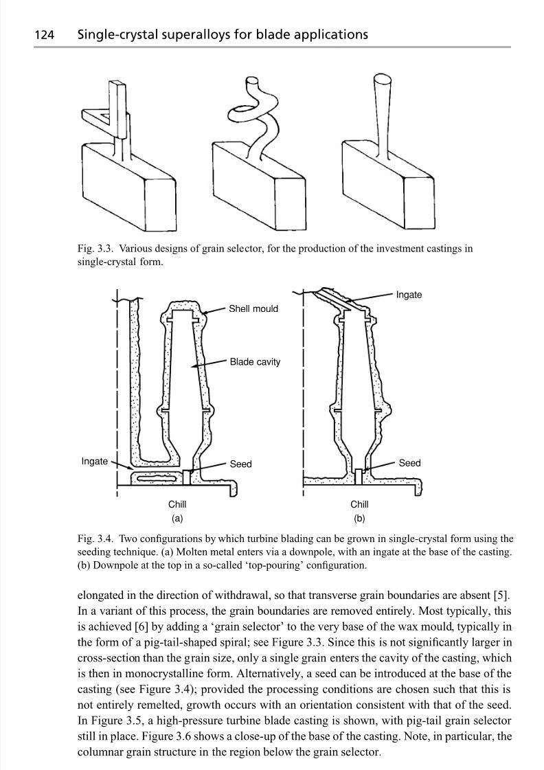
7/18/2019 The Superalloys Fundamentals and Applications
http://slidepdf.com/reader/full/the-superalloys-fundamentals-and-applications 142/389
124 Single-crystal superalloys for blade applications
Fig. 3.3. Various designs of grain selector, for the production of the investment castings in
single-crystal form.
Ingate
Shell mould
Blade cavity
Seed
Chill
(a) (b)
Ingate Seed
Chill
Fig. 3.4. Two configurations by which turbine blading can be grown in single-crystal form using theseeding technique. (a) Molten metal enters via a downpole, with an ingate at the base of the casting.
(b) Downpole at the top in a so-called ‘top-pouring’ configuration.
elongated in the direction of withdrawal, so that transverse grain boundaries are absent [5].
In a variant of this process, the grain boundaries are removed entirely. Most typically, this
is achieved [6] by adding a ‘grain selector’ to the very base of the wax mould, typically in
the form of a pig-tail-shaped spiral; see Figure 3.3. Since this is not significantly larger in
cross-section than the grain size, only a single grain enters the cavity of the casting, which
is then in monocrystalline form. Alternatively, a seed can be introduced at the base of thecasting (see Figure 3.4); provided the processing conditions are chosen such that this is
not entirely remelted, growth occurs with an orientation consistent with that of the seed.
In Figure 3.5, a high-pressure turbine blade casting is shown, with pig-tail grain selector
still in place. Figure 3.6 shows a close-up of the base of the casting. Note, in particular, the
columnar grain structure in the region below the grain selector.

7/18/2019 The Superalloys Fundamentals and Applications
http://slidepdf.com/reader/full/the-superalloys-fundamentals-and-applications 143/389
3.1 Processing of turbine blading 125
Fig. 3.5. Rolls-Royce Trent 800 high-pressure
turbine blade casting, after removal of the
investment shell.
Fig. 3.6. Details of the starter block and
pig-tail grain selector from the Trent 800
high-pressure turbine blade casting.

7/18/2019 The Superalloys Fundamentals and Applications
http://slidepdf.com/reader/full/the-superalloys-fundamentals-and-applications 144/389
126 Single-crystal superalloys for blade applications
Fig. 3.7. Schematic illustration [6] of the investment casting furnace used by Rolls-Royce plc for the production of single-crystal turbine blading.
Figure 3.7 is a schematic illustration [6] of the casting furnace used for the production
of turbine blading at Rolls-Royce plc, Derby, UK. The investment shell mould sits on
a copper chill plate of about 14 cm diameter; this size is sufficient for five HP turbine
blades for a civil jet engine to be produced simultaneously, or alternatively 20 for a smaller
helicopter engine. A bottom-run mould system is chosen, which allows the use of integral
ceramic filters to prevent ceramic particles from being swept into the blade cavities, whichare then filled in a controlled, predictable fashion. Since the diameter of the chill plate
is small, as little as 5 kg of charge needs to be melted. This is achieved, typically within
2 minutes, by using high-frequency (HF) induction melting in a disposable, refractory-fibre
crucible. The furnace consists of an upper melting chamber, a central mould chamber and
a lower withdrawal chamber, each of which are individually pumped and valved. Once a
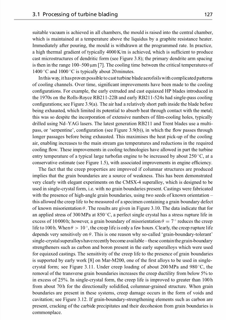
7/18/2019 The Superalloys Fundamentals and Applications
http://slidepdf.com/reader/full/the-superalloys-fundamentals-and-applications 145/389
3.1 Processing of turbine blading 127
suitable vacuum is achieved in all chambers, the mould is raised into the central chamber,
which is maintained at a temperature above the liquidus by a graphite resistance heater.
Immediately after pouring, the mould is withdrawn at the programmed rate. In practice,
a high thermal gradient of typically 4000 K/m is achieved, which is sufficient to produce
cast microstructures of dendritic form (see Figure 3.8); the primary dendrite arm spacing
is then in the range 100–500μ m [7]. The cooling time between the critical temperatures of
1400 ◦C and 1000 ◦C is typically about 20minutes.
In this way, it hasproven possible to cast turbine bladeaerofoilswith complicated patterns
of cooling channels. Over time, significant improvements have been made to the cooling
configurations. For example, the early extruded and cast equiaxed HP blades introduced in
the 1970s on the Rolls-Royce RB211-22B and early RB211-524s had single-pass cooling
configurations; see Figure 3.9(a). The air had a relatively short path inside the blade before
being exhausted, which limited its potential to absorb heat through contact with the metal;this was so despite the incorporation of extensive numbers of film-cooling holes, typically
drilled using Nd–YAG lasers. The latest generation RB211 and Trent blades use a multi-
pass, or ‘serpentine’, configuration (see Figure 3.9(b)), in which the flow passes through
longer passages before being exhausted. This maximises the heat pick-up of the cooling
air, enabling increases to the main stream gas temperatures and reductions in the required
cooling flow. These improvements in cooling technologies have allowed in part the turbine
entry temperature of a typical large turbofan engine to be increased by about 250 ◦C, at a
conservative estimate (see Figure 1.5), with associated improvements in engine efficiency.
The fact that the creep properties are improved if columnar structures are produced implies that the grain boundaries are a source of weakness. This has been demonstrated
very clearly with elegant experiments on the CMSX-4 superalloy, which is designed to be
used in single-crystal form, i.e. with no grain boundaries present. Castings were fabricated
with the presence of high-angle grain boundaries, using two seeds of known orientation –
this allowed the creep life to be measured of a specimen containing a grain boundary defect
of known misorientation θ . The results are given in Figure 3.10. The data indicate that for
an applied stress of 300 MPa at 850 ◦C, a perfect single crystal has a stress rupture life in
excess of 10000 h; however, a grain boundary of misorientation θ =
7◦
reduces the creep
life to 100 h. When θ > 10 ◦, the creep life is only a few hours. Clearly, the creep rupture life
depends very sensitively on θ . This is one reason why so-called ‘grain-boundary-tolerant’
single-crystalsuperalloyshaverecently become available – these contain thegrain-boundary
strengtheners such as carbon and boron present in the early superalloys which were used
for equiaxed castings. The sensitivity of the creep life to the presence of grain boundaries
is supported by early work [8] on Mar-M200, one of the first alloys to be used in single-
crystal form; see Figure 3.11. Under creep loading of about 200 MPa and 980 ◦C, the
removal of the transverse grain boundaries increases the creep ductility from below 5% to
in excess of 25%. In single-crystal form, the creep life is improved to greater than 100 hfrom about 70 h for the directionally solidified, columnar-grained structure. When grain
boundaries are present in these systems, creep damage occurs in the form of voids and
cavitation; see Figure 3.12. If grain-boundary-strengthening elements such as carbon are
present, cracking of the carbide precipitates and their decohesion from grain boundaries is
commonplace.

7/18/2019 The Superalloys Fundamentals and Applications
http://slidepdf.com/reader/full/the-superalloys-fundamentals-and-applications 146/389
128 Single-crystal superalloys for blade applications
(a)
(b)
500 μm
500 μm
Fig. 3.8. Scanning electron micrographs [7] of the dendritic microstructure of a single-crystal
superalloy, in the as-cast state. (a) 2.5 mm/min, conventional Bridgman furnace; (b) 2.5 mm/min
with liquid tin as a metal coolant. (Courtesy of Andrew Elliott.)

7/18/2019 The Superalloys Fundamentals and Applications
http://slidepdf.com/reader/full/the-superalloys-fundamentals-and-applications 147/389
3.1 Processing of turbine blading 129
Fig. 3.9. Schematic illustration of the cooling configurations used for turbine blade aerofoils.
(a) Single-pass cooling. (b) Multipass ‘serpentine’ cooling. In both cases, holes for film cooling
are present. (Courtesy of Rolls-Royce.)
The removal of the grain boundaries using a grain selector, or else by seeding, has rami-
fications for the crystallographic orientation of the casting. The preferred growth direction
for nickel and its alloys, in common with all known FCC alloys, is 001. Thus turbine
blade aerofoils have a 001 direction aligned along, or close to, the axis of the casting. The
texture arises as a consequence of the competitive growth of dendrites in the starter block of
the casting [9]; see Figure 3.13. The solid nuclei which form adjacent to the chill block have
an orientation which is random, but after only 1 mm of growth a strong 001-orientated
texture is present; see Figure 3.14. This effect occurs because the dendrites grow at a rate
which is largely controlled by solute diffusion, since the solid phase grows from the liquid
with a very different composition from it; thus the local dendrite tip undercooling, T tip,scales monotonically with the velocity, v, of the dendrite, measured along the temperature
gradient. It follows that dendrites which are misaligned by an angle θ with respect to per-
fectly aligned ones must grow at a greater undercooling and hence at the rear of the growth
front; see Figure 3.15. This provides an opportunity for the secondary and tertiary arms of
the well aligned dendrites to suppress the primary arms of those which are less so. The net

7/18/2019 The Superalloys Fundamentals and Applications
http://slidepdf.com/reader/full/the-superalloys-fundamentals-and-applications 148/389
130 Single-crystal superalloys for blade applications
800
700
600
500
400
300
200
100
01 10 100 1000 10 000
θ = 2°
7°
11° –13°
S t r e s s ( M P a )
Life (h)
Creepspecimen
Fig. 3.10. Variation of the creep rupture properties of the superalloy CMSX-4 at 850 ◦C, measured
on specimens with a single grain boundary of misorientation, θ , introduced. Note the very great
reduction in performance caused by the presence of the grain boundaries. (Courtesy of Bob
Broomfield.)
Fig. 3.11. Evolution of creep strain with time for the superalloy Mar-M200 under loading of
206 MPa and 982 ◦C, in the conventionally cast (equiaxed) state, the directionally solidified
(columnar) state and the single-crystal form [8].
result is a reduction in the number of grain boundaries and the establishment of a strong
001
-orientated texture.
3.1.2 Analysis of heat transfer during directional solidification
In practice, directional solidification requires careful control of the rate of heat removal
from the casting. Mathematical analysis of the heat transfer processes is therefore useful,
since it provides insight into the effects occurring.

7/18/2019 The Superalloys Fundamentals and Applications
http://slidepdf.com/reader/full/the-superalloys-fundamentals-and-applications 149/389
3.1 Processing of turbine blading 131
Fig. 3.12. Scanning electron micrographs of the grain boundaries in the directionally solidified superalloy RR2072, modified with 0.05 wt%C and 0.005 wt%B. (a) 18.8◦ misorientation, crept to 64
hours (80% of creep life); (b) 10.5◦ misorientation, crept to 100 hours (50% of creep life). (Courtesy
of Quizi Chen.)
A Treatment of infinite rod – estimation of withdrawal velocity
One can make a first estimate of the maximum speed at which the casting should be removed
from the furnace in the following way. As a first approximation, one treats the casting as
an infinite, cylindrical rod; this moves at a uniform rate, v, from a furnace of temperature
T 1 into a medium of ambient temperature T 0; see Figure 3.16. The heat flow is taken to beunidirectional, i.e. it occurs only in the axial direction (denoted x). The temperature field,
T { x}, comes to a steady-state, which satisfies the heat flow equation in the moving frame,
κ∂2T
∂ x2+ vc
∂ T
∂ x+ Q = 0 (3.1)
where Q is the local volumetric rate of heat production or extraction, c is the volumetric
specific heat capacity and κ is the thermal conductivity. At the melting temperature, when
T
=T m (note T 1 > T m > T 0), the production of latent heat occurs; this requires that the
following boundary condition is satisfied at the solid/liquid interface:
κs
∂ T
∂ x
s
= κl
∂ T
∂ x
l
+ Lv (3.2)
where L is the volumetric latent heat of fusion and the subscripts s and l refer to the solid and
liquid, respectively. Conversely, heat is extracted at a rate q = heff (T − T 0) by Newtonian

7/18/2019 The Superalloys Fundamentals and Applications
http://slidepdf.com/reader/full/the-superalloys-fundamentals-and-applications 150/389
132 Single-crystal superalloys for blade applications
Fig. 3.13. Grain structure in the starter block of a single-crystal turbine blade casting, cast from
CMSX-4; the chill block is at the bottom and the growth direction is upwards. (a) Results from
theoretical calculations made using the phase-transformation theory. (b) Experimental analysis
using electron back-scattered diffraction patterns of the starter block in Figure 3.6, confirming the
evolution of the 001 texture. Data taken from ref. [9].
Fig. 3.14. (a) Measured and (b) predicted 001 pole figures taken from the starter block shown in
Figure 3.6 at various heights above the chill block [9].

7/18/2019 The Superalloys Fundamentals and Applications
http://slidepdf.com/reader/full/the-superalloys-fundamentals-and-applications 151/389
3.1 Processing of turbine blading 133
Fig. 3.15. Illustration of the competitive grain growth process, in which misaligned dendrites are
suppressed by the secondary arms of well aligned ones.
Coolingzone
Heatingzone
Solid
Liquid
D i s t a n c e , x
v
r
T 0 T m T 1
Temperature
Fig. 3.16. The directional solidification of an infinite rod emerging from a semi-infinite furnace into
a semi-infinite heat sink, at a velocity consistent with the temperature at the exit of the furnace equal
to the melting temperature. Adapted from ref. [3].

7/18/2019 The Superalloys Fundamentals and Applications
http://slidepdf.com/reader/full/the-superalloys-fundamentals-and-applications 152/389
134 Single-crystal superalloys for blade applications
heat transfer at the surfaces which have emerged from the furnace – the term heff is the
associated heat-transfer coefficient. Under these circumstances, it can be shown that the
temperature field is given by [10,11]
T { x} = T 0 + (T m − T 0)exp{βs x} , x < 0 (3.3a)
and
T { x} = T 1 − (T 1 − T m)exp{−βl x} , x > 0 (3.3b)
where
βs =
2heff
κsr +
vc
2κs
21/2
− vc
κs
(3.4a)
and
βl =vc
κl
(3.4b)
where the transition from the heating to the cooling medium is assumed to occur abruptly
at x = 0; see Figure 3.16.
With these assumptions, one can derive an expression for the velocity at which the
casting can be removed from the furnace, by substituting into the Stefan condition (given
by Equation (3.2)) expressions for the temperature gradients at the solid/liquid interface –
this is left as an exercise for the reader. One finds [11]
v = 1
c
2heff κs
r
1/2
(Z 1/2 − Z −1/2) (3.5a)
where
Z = L + c(T 1 − T 0)
L + c(T 1 − T m)(3.5b)
Note that if the casting speed is any greater than this value, solidification will not be
completed before the casting leaves the furnace; this is not satisfactory since, in this case,
a temperature gradient will be set up in the radial direction, which provokes the onset
of defects such as freckles – this will be discussed further in Section 3.1.3. The analysis
indicates that the critical velocity, v, is proportional to the square root of the heat transfer
coefficient, heff . With T 1 = 1800K, T 0 = 300 K, T m = 1650 K, L = 2 × 10⁹ J/m3 and c =4 × 10⁶ J/(m3 K) then Z ∼ 3, so the last term in Equation (3.5a) is approximately unity. For
a conventional investmentcasting furnace, a reasonable valuefortheheat transfer coefficient
is heff = 50 W/(m2 K), once a steady-state is attained. Taking κs = 15 W/(m K) and r =0.02m, one finds that the velocity, v, is about∼0.1 mm/s. This estimate is not very far from
the values used in commercial furnaces for the casting of high-pressure turbine blades [9].The temperature gradient, G , at the solidus can be determined from Equation (3.3a); it is
(T m − T 0)βs, or about 75 K /cm, given the estimates that have been made.
In this analysis it has been assumed that there is no heat loss from the furnace to the
cooling zone. This is impossible to achieve in practice, although much effort has been
expended in designing optimum baffle arrangements by placing radiation shields at the
base of the furnace, with openings just large enough to allow the castings to emerge from

7/18/2019 The Superalloys Fundamentals and Applications
http://slidepdf.com/reader/full/the-superalloys-fundamentals-and-applications 153/389
3.1 Processing of turbine blading 135
the furnace. These have been shown to be efficient at keeping the solid/liquid interface flat,
and in the vicinity of the baffle.
B Comparison of axial and transverse contributions to heat transfer
The above analysis indicates that, at steady-state, a balance exists between (i) the rate of
heat extraction by conduction along the casting in the axial direction, and (ii) the rate
of transverse heat loss by radiation through the curved, cylindrical surfaces. It follows
that, as the casting first emerges from the furnace, this equilibrium has yet to be attained.
The conditions pertaining to these early stages of directional solidification are important,
particularly for single-crystal castings, since they govern the processes of competitive grain
growth, texture development and grain selection.
At the beginning of directional solidification, the primary source of heat loss is dueto conduction to the chill through the solidified portion of the ingot; this contribution
diminishesas X , thelengthof thesolidified ingot, increases. Thereafter, heat loss byradiation
is expected to dominate, at least whilst the casting and ceramic investment shell remain in
close contact and provided that the investment shell is relatively thin. The heat flux, q,
should therefore be represented accurately by [3,12]
q = heff (T − T 0) = (hC + hR )(T − T 0) (3.6)
where heff has now been partitioned into two terms, hC and hR , corresponding to the heat
transfer coefficients for axial conduction and transverse radiation, respectively; these aregiven by
hC =κs
X (3.7)
and
hR =σ
T 4 − αT 40
T − T 0(3.8)
where σ is the Stefan constant, is the emissivity of the ingot and α is the absorbtivity of
the surroundings.
It is helpful to determine the length of the ingot which solidifies before the steady-state is
attained. If = α = 0.45 and σ = 5.67× 10⁻⁸ J/(m2 s K 4), T = 1500 K and T 0 = 400 K,
then
hR = 120W/(m2 K) (3.9)
and, with κs = 16 W/(mK),
hC
=1600W/(m2 K) (3.10)
when X = 10 mm. Thus, initially, hC > hR ; however, at the point when X = 130mm the
two contributions are equal, and soon thereafter cooling is controlled by radiative heat
transfer. The dominance of the radiative mode at later times is aided also by the relatively
small cross-sectional area available for conduction through the copper chill, the presence
of a grain selector and the substantial surface area of the mould, particularly for turbine
blades which are of complex shape. It is clear therefore that, in practice, only the first part

7/18/2019 The Superalloys Fundamentals and Applications
http://slidepdf.com/reader/full/the-superalloys-fundamentals-and-applications 154/389
136 Single-crystal superalloys for blade applications
of the casting is cooled effectively by conduction of heat through the water chill; for the
majority of the casting one is relying upon radiation to the water-cooled walls of the vacuum
chamber.
C Effects of quenching medium – liquid metal cooling
Equation (3.5a) indicates that the velocity of withdrawal, v, scales inversely with√
r , the
square root of the radius of the casting; thus, for castings of significant size, the time neces-
sary for solidification to be completed can become prohibitively long. A further difficulty is
that the economics of the single-crystal casting process depend also upon the yield, which is
decreased if defects such as freckles, spurious grains and low-angle boundaries are formed;
this is most likely to occur when the temperature gradient is low since the width of the semi-
solid ‘mushy’ region is then considerable. The temperature gradient, G , is proportional tothe parameter βs in Equation (3.3a) – and Equation (3.4a) confirms that this decreases as
r increases. Thus, the tendency for grain defect formation is enhanced for components of
larger size. An additional challenge is that it becomes increasingly difficult to keep the pro-
file of the solid/liquid interface flat as the casting becomes large; this can further increase the
probability of defect formation, particularly freckles. These considerations are particularly
pertinent to the casting of the blades for an industrial gas turbine (IGT) used for electricity
generation – these might be about 500 mm long with a mass in excess of 5 kg.
Under these circumstances, more efficient methods are being sought for cooling the
mould as it emerges from the furnace [13]. The rationale for this is as follows: a larger heff has the effect of increasing v and G , as indicated by Equations (3.3), (3.4) and (3.5).
Enhanced cooling has been achieved in the laboratory by various means, including water
sprays, fluidised bed cooling, gas cooling using jets of Ar/He mixtures, and liquid metal
cooling; all depend upon a close thermal contact of the mould and the cooling medium. Of
the different techniques, the liquid metal cooling (LMC) technique appears to be the most
likely to make the transition into the commercial foundry – indeed it has been used already
in Russia. The mould is immersed into a bath of molten metal to increase the heat transfer
rate (see Figure 3.17). The choice of liquid metal coolant is important – the requirements are
a low melting temperature, low vapour pressure, high thermal conductivity, low viscosity,
lack of toxicity and low cost, on account of the quantities of metal required. For these
reasons, aluminium and tin have emerged as the prime candidates for the LMC process.
The important physical properties of the two metals are listed in Table 3.1. Although the
vapour pressures of Al and Sn are more or less equivalent, the lower melting temperature
of Sn is advantageous since it allows a lower bath temperature to be used. The thermal
conductivity of Al is considerably higher than for Sn, which might indicate that heat transfer
by conduction through the molten metal will be particularly effective.
In order to compare the advantages of Sn and Al as coolants for the LMC process, onemust consider in more detail the various resistances to heat flow arising as the ingot and
mouldare immersed into the liquidmetal.The conventional Bridgmanprocess is considered
first. Theconduction andradiationcoefficients, hC and hR , must be considered as before; the
estimates of 1600 W/(m2 K) and 120 W/(m2 K) of Equations (3.9) and (3.10), respectively,
are used again. However, for large IGT castings one must include the coefficient hgap, to
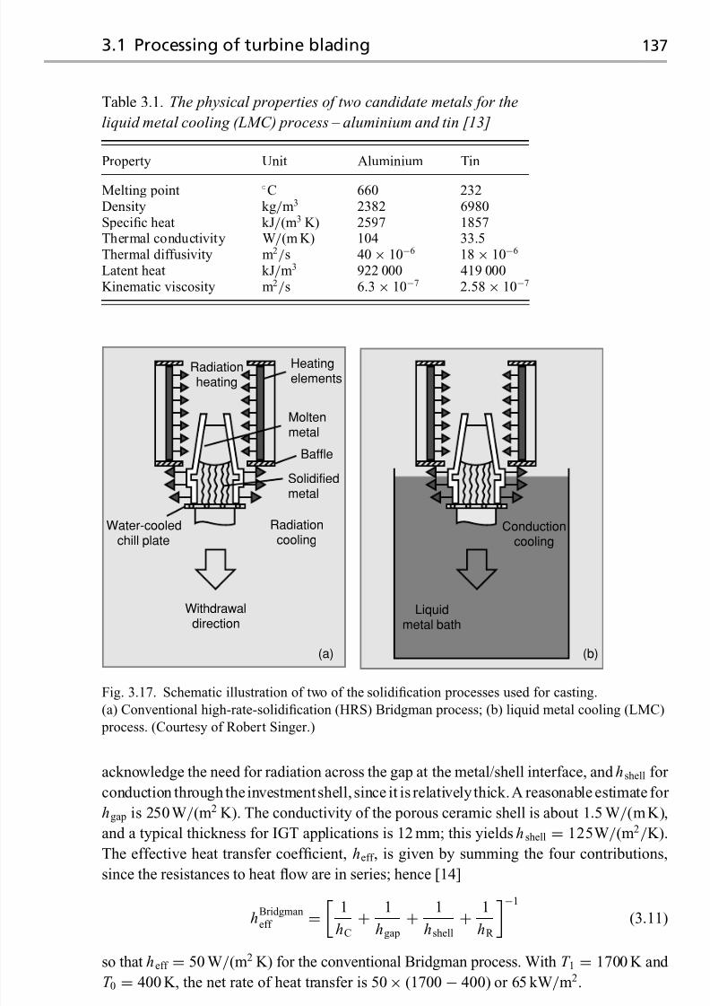
7/18/2019 The Superalloys Fundamentals and Applications
http://slidepdf.com/reader/full/the-superalloys-fundamentals-and-applications 155/389
3.1 Processing of turbine blading 137
Table 3.1. The physical properties of two candidate metals for the
liquid metal cooling (LMC) process – aluminium and tin [13]
Property Unit Aluminium Tin
Melting point ◦C 660 232Density kg/m3 2382 6980Specific heat kJ/(m3 K) 2597 1857Thermal conductivity W/(m K) 104 33.5Thermal diffusivity m2/s 40× 10−6 18 × 10−6
Latent heat kJ/m3 922 000 419 000Kinematic viscosity m2/s 6.3× 10⁻⁷ 2.58 × 10⁻⁷
Radiationheating
Heatingelements
Moltenmetal
Baffle
Solidifiedmetal
Radiationcooling
Conductioncooling
Liquidmetal bath
Withdrawaldirection
Water-cooledchill plate
(a) (b)
Fig. 3.17. Schematic illustration of two of the solidification processes used for casting.
(a) Conventional high-rate-solidification (HRS) Bridgman process; (b) liquid metal cooling (LMC)
process. (Courtesy of Robert Singer.)
acknowledge the need for radiation across the gap at the metal/shell interface, and hshell for
conduction through theinvestmentshell, since it is relatively thick.A reasonable estimate for
hgap is 250 W/(m2 K). The conductivity of the porous ceramic shell is about 1.5 W/(mK),
and a typical thickness for IGT applications is 12 mm; this yields hshell = 125W/(m2/K).
The effective heat transfer coefficient, heff , is given by summing the four contributions,
since the resistances to heat flow are in series; hence [14]
hBridgmaneff =
1
hC
+ 1
hgap
+ 1
hshell
+ 1
hR
−1
(3.11)
so that heff = 50 W/(m2 K) for the conventional Bridgman process. With T 1 = 1700 K and
T 0 = 400 K, the net rate of heat transfer is 50× (1700 − 400) or 65 kW/m2.

7/18/2019 The Superalloys Fundamentals and Applications
http://slidepdf.com/reader/full/the-superalloys-fundamentals-and-applications 156/389
138 Single-crystal superalloys for blade applications
00
20
40
60
80
100
20 40 60
LMC
80 100 120
Withdrawal
Power-down
G r o w t h r a t e ( c m / h )
Thermal gradient (°C/cm)
Fig. 3.18. Ranges of thermal gradients and growth rates for the three solidification processes
appropriate for turbine blade castings: (i) the power-down process, (ii) the conventional withdrawal
(Bridgman) process and (iii) the liquid metal cooling (LMC) process [12]. The arrows indicate
directions in which changes in processing conditions can be accomplished easily.
For the LMC process, the contribution from hR is no longer appropriate and it is replaced with a term, hLMC, which describes the conduction of heat in the liquid metal. The liquid
metal is an efficient heat sink so that hLMC hR – this is true regardless of whether Al or
Sn is used as the coolant. Thus, hLMC does not contribute significantly to the resistance to
heat flow; hence,
hLMCeff =
1
hC
+ 1
hgap
+ 1
hshell
−1
(3.12)
so that heff = 80 W/(m2 K). The net rate of heat transfer is then given by heff (T − T bath),
where T bath is the bath temperature; appropriate values are 950 K and 550 K for Al and Sn,
respectively. With T = 1700 K, the net rates of heat transfer are then 80× (1700 − 950) or
60kW/m2 for Al and 80 × (1700− 550) or 90 kW/m2 for Sn. These calculations confirm
that the net rate of heat extraction can be improved markedly if molten Sn is used as a
cooling medium. Liquid Al, on the other hand, does not improve matters appreciably –
in fact, these calculations indicate that the net rate of heat transfer is lower than for the
conventional Bridgman technique. This is a consequence of the higher bath temperature
required by the higher melting temperature of Al.In Figure 3.18, the growth rates and withdrawal velocities typical of the LMC process are
compared with those which can be achieved using the conventional Bridgman (withdrawal)
and power-down methods [12]. Liquid Sn is used as the cooling medium. One can see that
the LMC process affords an increased thermal gradient of at least a factor of 3, and a growth
velocity of at least a factor or 2, when compared to the conventional Bridgman method.

7/18/2019 The Superalloys Fundamentals and Applications
http://slidepdf.com/reader/full/the-superalloys-fundamentals-and-applications 157/389
3.1 Processing of turbine blading 139
High-angle boundaries
Blocked core
Recrystallisation
Inclusions
Aerofoil shape
Aerofoil wall
Furnace malfunction
FaultSix-monthaverage
FaultSix-monthaverage
Orientation 8.0%
5.8%
3.1%
3.0%
2.3%
2.3%
2.2%
1.1%
Overall yield 69% Overall yield 67%
Inclusions
High-angle boundaries
Core breakthrough
Root wall
Freckles
Aerofoil shape
Furnace malfunction
Blocked core
Recrystallisation
4.7%
4.6%
3.5%
3.4%
2.2%
2.1%
2.0%
1.4%
1.1%
(a) (b)
Fig. 3.19. Non-conformance statistics for two single-crystal castings processed in a commercial
foundry: (a) seeded blade cast from second-generation alloy, and (b) blade cast from
third-generation alloy, with a grain selector.
3.1.3 Formation of defects during directional solidification
A decision to cast a turbine blade aerofoil in single-crystal form represents a considerable
challenge to the foundry. This is because very stringent requirements are then placed on the
quality of the casting that can be accepted. Defects, such as high-angle grain boundaries,
which arise when the grain selector fails to function properly or else due to nucleation
of spurious grains around re-entrant features such as platforms and shrouds, cannot be
tolerated. The crystallographic orientation must be such that the 001 direction is closely
aligned to the axis of the casting – usually within 15◦ or so; in practice, the use of a grain
selector or seed fails to ensure that this happens completely routinely. Recrystallisation
during subsequent solutioning heat treatment, driven by plastic strains introduced by the
shrinkage of the metal around the ceramic core, introduces high-angle grain boundaries,
and therefore necessitates rejection [15]. Additional requirements, common to columnar
or equiaxed castings used for lower-temperature applications such as low-pressure (LP)
blading,must also be respected.The design of the component requires that tight dimensional
tolerances are placed on the shape of the aerofoil and, if the blading is hollow, the thicknessof its walls. The presence ofentrained ceramic particles swept into the molten metal fromthe
shell cannot be tolerated since they impair the fatigue properties; these are detected during
the non-destructive inspection using radiographic methods. Given these considerations, it
is clear that the probability of component rejection casting is likely to be reasonably high.
The data in Figure 3.19, which are taken from a typical commercial foundry specialising in

7/18/2019 The Superalloys Fundamentals and Applications
http://slidepdf.com/reader/full/the-superalloys-fundamentals-and-applications 158/389
140 Single-crystal superalloys for blade applications
Fig. 3.20. Photographs of sections of blade castings illustrating the presence of defects:
(a) high-angle grain boundaries; (b) freckle chains.
the casting of blading in single-crystal form, confirm this. For the seeded casting, failure to
control the orientation of the blading is the major cause of non-conformance; this problemdisappears when a grain selector is employed, but in both cases the overall yield is rather
low at around 70%. Images of castings with grain defects are shown in Figure 3.20.
Case study: The freckle defect
The above data indicate that there are many possible defects which can arise when casting a
turbine blade in single-crystal form. Of these, the phenomenon of freckling [16] is worthy
of further consideration since the probability of its occurrence has been found to be strongly
dependent upon the composition of the alloy being cast – the third- or fourth-generation
alloys, which are rich in elements such as Re, are particularly prone to this effect. Freck-
les, also known as channel segregates, are thin chains of equiaxed grains associated with
localised heterogeneities in chemical composition; see Figure 3.20(b). Single-crystal cast-
ings, both for aeroengine and IGT applications, can exhibit the freckling phenomenon. The
localisation is always found to be on the scale of the primary dendrite arm spacing, with the
freckles being found in the interdendritic regions. Chemical analysis of the freckle chains
confirms that they are enriched with regard to elements which partition to the interdendritic
liquid, for example Al, Ti, Ta and Nb, where these are present.There are other pieces of evidence which shed light on the mechanism by which freckles
form. Consider Figure 3.21, which summarises the results from a considerable programme
of experimental work carried out by Tin, Pollock and co-workers aimed at identifying the
factors whichpromote freckling[17]. More than 16 differentalloyswere cast into cylindrical

7/18/2019 The Superalloys Fundamentals and Applications
http://slidepdf.com/reader/full/the-superalloys-fundamentals-and-applications 159/389
3.1 Processing of turbine blading 141
30
25
20
15
10
5
0
A v e r a g e n u m b e r o f f r e c k l e c h a i n s
Alloy number
1 2 3 4 5 6 7 8 9 10 11 12 13 14 15 16
7.1Al
2.4W
1.5Re
4.6Al
7.4W
1.4Re
6.5Al
7.0W
4.4Re4.8Al
2.5W
1.5Re
6.8Al
2.4W
4.6Re
6.7Al
7.3W1.4Re
4.4Al
7.2W
4.4Re
4.6Al
2.4W
4.7Re
With carbon
12.7 mm diameter bars
15.9 mm diameter bars
19.0 mm diameter bars
Fig. 3.21. Statistics for the formation of freckle chains in cast bars of varying diameters, in
superalloys of various compositions [17]. For all alloys, Ta∼ 6.1, Hf ∼ 0.14. All numbers refer to
concentrations in wt%.
bars of three different diameters: 12.7 mm, 15.9 mm and 19.0 mm, at otherwise identicalconditions. Some of the alloys were deliberately doped with carbon. The average number of
freckle chains appearing on the surface of the castings was then characterised. A number of
interesting observations are seen. First, the extent of freckling becomes more pronounced
as the bar diameter increases. Second, there is a greater tendency for freckling when the
combined W and Re content, i.e. W + Re, is significant. Third, additions of carbon are
found to be effective at reducing the degree of freckling. Finally, and significantly, when
casting is carried out at different casting conditions (see Figure 3.22) it is found that there
is a critical minimum primary dendrite arm spacing (corresponding to a lower limit for the
temperature gradient) below which freckles are not found [18].
These observations support the following mechanism for the freckling effect. On ther-
modynamic grounds, the alloying additions prefer to partition to either the interdendritic
regions or alternatively to the dendrites themselves. Experiments using electron probe mi-
croanalysis (EPMA) indicate that Re and W segregate to the dendrite core, and that Al, Ti
and Ta partition to the interdendritic regions [19]; see Figure 3.23. Other elements such as
Cr, Co and Ru are found to be rather neutral in partitioning behaviour, with a partitioning
coefficient close to unity. Particularly when the Re and W contents are large, liquid in the
interdendritic region becomes depleted in these heavy elements, causing it to become lighter than the liquid at a temperature closer to the liquidus. Thus, a so-called ‘density inversion’
becomes possible [20]. For freckling to occur, the enhanced buoyancy of the interdendritic
liquid (due to the loss of heavy elements) must overcome frictional effects which prevent
the lighter liquid from rising – if this occurs, then thermosolutal convection currents, or

7/18/2019 The Superalloys Fundamentals and Applications
http://slidepdf.com/reader/full/the-superalloys-fundamentals-and-applications 160/389
142 Single-crystal superalloys for blade applications
100 200 300 400 500 600
Primary dendrite arm spacing (μm)
F r e c k l e c h a i n s
0
5
10
15
20
25
Fig. 3.22. Dependence of the number of freckle chains on the primary dendrite arm spacing. Note
that the critical spacing for the formation of freckles is ∼300 μ m [18].
‘freckle plumes’, are set up. When casting is of significant cross-sectional area, the width of
the mushy zone is wide, and freckling is exacerbated. Similarly, additions of elements such
as Re and W, which exacerbate the density inversion on account of their partitioning be-
haviour, promote freckling; conversely, elements such as Ta restrict it. Additions of carbon
cause the formation of carbides at temperatures around the liquidus, and these appear to be
responsible for its beneficial effect [17]. When the dendrite arm spacing is low, freckling
does not occur since any possible density inversion provides insufficient driving force to
overcome the resistance to interdendritic fluid flow, since the permeability of the mushy
zone is then low.
That the single-crystal superalloys are prone to the freckle defect can be seen by mak-
ing calculations for the density of the liquid phase as the function of temperature; see
Figure 3.24. Experimental measurements for the density of liquid CMSX-4 above the melt-
ing temperature (about 1650K) have been reported in ref. [21]; these data are plotted on
the figure, along with an extrapolation to lower temperatures (the dotted line), which rep-
resents the density of the unpartitioned liquid in the mushy zone. Estimates of the density
of the partitioned liquid can be made assuming equilibrium is attained, by accounting for
the mass loss due to the partitioning of elements such as Re and W into the solid phase.The density of the partitioned liquid is given by the curved solid line. The driving force for
freckling is proportional to the difference between the solid and dotted lines, denoted ρ;
for CMSX-4 it is a maximum at about 20K below the melting temperature. These calcula-
tions can be carried out for single-crystal superalloys of different compositions, for example
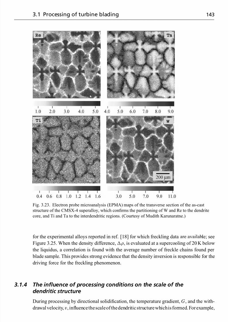
7/18/2019 The Superalloys Fundamentals and Applications
http://slidepdf.com/reader/full/the-superalloys-fundamentals-and-applications 161/389
3.1 Processing of turbine blading 143
Fig. 3.23. Electron probe microanalysis (EPMA) maps of the transverse section of the as-cast
structure of the CMSX-4 superalloy, which confirms the partitioning of W and Re to the dendrite
core, and Ti and Ta to the interdendritic regions. (Courtesy of Mudith Karunaratne.)
for the experimental alloys reported in ref. [18] for which freckling data are available; see
Figure 3.25. When the density difference, ρ, is evaluated at a supercooling of 20 K below
the liquidus, a correlation is found with the average number of freckle chains found per
blade sample. This provides strong evidence that the density inversion is responsible for the
driving force for the freckling phenomenon.
3.1.4 The influence of processing conditions on the scale of thedendritic structure
During processing by directional solidification, the temperature gradient, G , and the with-
drawalvelocity, v, influencethescaleof thedendriticstructurewhichis formed. Forexample,

7/18/2019 The Superalloys Fundamentals and Applications
http://slidepdf.com/reader/full/the-superalloys-fundamentals-and-applications 162/389
144 Single-crystal superalloys for blade applications
Fig. 3.24. Variation of the density of liquid CMSX-4 with temperature. The data beyond 1650 K are
those recommended by ref. [21] – the dotted line represents an extrapolation below the liquidus. The
solid line below 1650K represents the calculated density of the liquid in the mushy zone, assuming
equilibrium is attained; thus, the effect of solute partitioning is accounted for.
the use of liquid metal cooling is found to decrease the dendrite arm spacing at otherwise
identical withdrawal velocity; see Figure 3.8. It is helpful to estimate the relative potencies
of G and v on the scale of the microstructure to be expected, for example the primary
dendrite arm spacing, L p.
In order to do this, consider first the temperature interval, T 0, required for solidifi-
cation to be completed. If the phase diagram is taken to be a binary one with a liquidus
of slope m and a solid/liquid partitioning coefficient of k , then it can be demonstrated
that T 0 is given by mc0(k − 1)/ k , where c0 is the bulk composition of the alloy under
consideration. The scale of the dendritic structure is then as depicted in Figure 3.26. The
dendrites are assumed to possess a radius of curvature R at their tips, which are spaced
a distance L p apart. The mean height of the dendrite trunks is then T 0/G , where G is
the temperature gradient; the thickness of the trunks at their roots is given the symbol λ,
which is approximately one half of L p. A steady-state is assumed – thus, the dendritic
structure translates at a velocity v, and its shape is invariant as it does so. A first esti-
mate of the radius of curvature of the tip of each dendrite is given by fitting a parabola
to its shape [22]; from elementary geometry, it is then equal to the ratio of the square of the minor axis of the parabola (which is equal to λ) to the major axis (T 0/G ) – so that
R = λ2G /T 0.
For thesolidification conditions pertinent to thesuperalloys, therearetwo contributions to
the totalundercooling T . The first is due to the solutal undercooling, T solutal, arising from
the partitioning of solute; the second, T curvature, is a consequence of the Gibbs–Thomson

7/18/2019 The Superalloys Fundamentals and Applications
http://slidepdf.com/reader/full/the-superalloys-fundamentals-and-applications 163/389
3.1 Processing of turbine blading 145
Fig. 3.25. Data for the freckling propensity of a number of experimental single-crystal superalloys
[18]. (a) Average number of freckle chains per blade sample; (b) corresponding differences between
the densities of the unpartitioned and partitioned liquid at an interval of 20 K below the liquid of the
alloy concerned. Note the correlation between the data in (a) and (b).

7/18/2019 The Superalloys Fundamentals and Applications
http://slidepdf.com/reader/full/the-superalloys-fundamentals-and-applications 164/389
146 Single-crystal superalloys for blade applications
λ
R
Parabolamodel
v ΔT 0 / G , where ΔT 0 = solidification range
Lp
Fig. 3.26. Schematic illustration of the geometry of the dendritic structure at steady-state: the
primary arm spacing is L p, and the major and minor axes of the paraboloid of revolution fitted to the
dendrite tip are T 0/G and λ = L p/2, respectively.
effect. Thus, provided that the undercooling is small,
T = T solutal + T curvature
= mc0(1− k ) + 2θ/ R (3.13)
since, for ∼ 0, it can be demonstrated that T solutal is approximately mc0(1− k ). The
term θ is the Gibbs–Thomson coefficient; the factor of 2 arises because the dendrites
are taken to be paraboloids of revolution, so that their tips are hemispherical. Consistent
with the growth of an isolated dendrite tip, see the Appendix to this chapter, the super-saturation, , is given by = Rv/ D, where D is the diffusion coefficient of solute in
the liquid ahead of the front. Making this substitution, along with R = λ2G /T 0, one
has
T = mc0(1− k ) v
2 D
λ2G
T 0
+ 2θ T 0
λ2G (3.14)
Equation (3.14) represents an expression for the dependence of the undercooling, T ,
upon the three variables λ
=L p/2, G and v. One of these can be eliminated using a
further equation or criterion [22]. For example, one can invoke the extremum condi-
tion, which states that growth will occur at whatever λ minimises T or maximises
v. This implies that ∂T /∂λ = 0; after some algebraic manipulation, one can show
that
vG 2λ4 = 4θ Dmc0(1 − k ) (3.15)
or alternatively
vG 2 L4 p
=64θ Dm c0(1
−k ) (3.16)
Note that the terms on the right-hand side of Equation (3.16) are expected to be invariant for
any given alloy system. Thus, the primaryarm spacing, L p, is predicted to be proportional to
G −1/2v−1/4. It follows that G is expected to have a more profound influence on the spacing
than v – as found, for example, in the liquid metal cooling process. The experimental results

7/18/2019 The Superalloys Fundamentals and Applications
http://slidepdf.com/reader/full/the-superalloys-fundamentals-and-applications 165/389
3.2 Optimisation of single-crystal superalloys 147
600
500
400
300
200
100
0 P
r i m a r y d e n d r i t e a r m
s p a c i n
g ( μ m )
0 0.1 0.2 0.3 0.4
Mar-M247
PWA1484
René 108
René N5
IN718
Mar-M246
Mar-M002
IN738LC
IC50
Ni–Al–Cr–Fe
G −1/2v −1/4 (m1/4 s1/4 /K1/2)
Fig. 3.27. Data [23] for the variation of the primary dendrite arm spacing with the combination
G −1/2v−1/4, where G is the temperature gradient and v is the withdrawal velocity, for a number of
commercial superalloys.
confirm this (see Figure 3.27),whichprovides data [23] for theprimarydendrite arm spacingfor a number of commercial superalloys solidified under a range of G and v conditions.
The agreement between the experimental data and the theory gives some credence to the
use of the extremum condition in deriving it, despite the lack of a firm physical basis for its
application.
3.2 Optimisation of the chemistry of single-crystal superalloys
Over a period of about 20 years, the chemistry of the single-crystal superalloys has been
refined in order to improve the properties displayed. Although much of this progress has
been incremental, a clear picture has emerged of the roles played by the various elements
in conferring the best properties. Whilst it should be remembered that the various alloy
producers and engine manufacturers have settled on proprietary chemistries to maintain
their competitive advantage, the compositionsof the single-crystal superalloys have evolved
significantly in the period since 1980 when the first ones emerged. The compositions of
important first-, second-, third- and fourth-generation single-crystal superalloys are given
in Tables 3.2, 3.3, 3.4 and 3.5. Of note is the introduction of significant additions of Re, and the reduction of Ti and Mo to low concentrations. Some interesting insights into the early
alloy development efforts are given in refs. [24] and [25]. With the benefit of hindsight, the
improvements in performance have been won by respecting the four guidelines set out on
pp. 152–170.

7/18/2019 The Superalloys Fundamentals and Applications
http://slidepdf.com/reader/full/the-superalloys-fundamentals-and-applications 166/389
T a b l e 3 . 2 . T h e c o m p o s i t i o n s ( i n w e i g h t % ) o f s
e l e c t e d fi r s t - g e n e r a t i o n s i n g
l e - c r y s t a l s u p e r a l l o y s
A l l o y
C r
C o
M o
W
A l
T i
T a
N b
V
H f
N i
D e n s i t y ( g / c m 3 )
N a s a i r 1 0 0
9
—
1
1 0 . 5
5 . 7 5
1 . 2
3 . 3
—
—
—
B a l
8 . 5 4
C M S X - 2
8
4 . 6
0 . 6
8
5 . 6
1
6
—
—
—
B a l
8 . 6 0
C M S X - 6
9
. 8
5
3
—
4 . 8
4 . 7
2
—
—
0 . 1
B a l
7 . 9 8
P W A 1 4 8 0
1 0
5
—
4
5
1 . 5
1 2
—
—
—
B a l
8 . 7 0
S R R 9 9
8
5
—
1 0
5 . 5
2 . 2
3
—
—
—
B a l
8 . 5 6
R R 2 0 0 0
1 0
1 5
3
—
5 . 5
4
—
—
1
—
B a l
7 . 8 7
R e n e N 4
9
8
2
6
3 . 7
4 . 2
4
0 . 5
—
—
B a l
8 . 5 6
A M 1
7
. 8
6 . 5
2
5 . 7
5 . 2
1 . 1
7 . 9
—
—
—
B a l
8 . 6 0
A M 3
8
5 . 5
2 . 2 5
5
6
2
3 . 5
—
—
—
B a l
8 . 2 5
T M S - 6
9
. 2
—
—
8 . 7
5 . 3
—
1 0 . 4
—
—
—
B a l
8 . 9 0
T M S - 1 2
6
. 6
—
—
1 2 . 8
5 . 2
—
7 . 7
—
—
—
B a l
9 . 0 7

7/18/2019 The Superalloys Fundamentals and Applications
http://slidepdf.com/reader/full/the-superalloys-fundamentals-and-applications 167/389
T a b l e 3 . 3 . T h e c o m p o s i t i o n s ( i n w e i g h t % ) o f s
e l e c t e d s e c o n d - g e n e r a t i o n s i n g l e - c r y s t a l s u p e r a l l o y s
A l l o y
C r
C o
M o
R e
W
A l
T i
T a
N b
H f
N i
D e n s i t y ( g / c m 3 )
C M S X - 4
6 . 5
9
0 . 6
3
6
5 . 6
1
6 . 5
—
0 . 1
B a l
8 . 7 0
P W A 1 4 8 4
5
1 0
2
3
6
5 . 6
—
8 . 7
—
0 . 1
B a l
8 . 9 5
R e n e N 5
7
8
2
3
5
6 . 2
—
7
—
0 . 2
B a l
8 . 7 0
M C 2
8
5
2
—
8
5
1 . 5
6
—
—
B a l
8 . 6 3
T M S - 8 2 +
4 . 9
7 . 8
1 . 9
2 . 4
8 . 7
5 . 3
0 . 5
6
—
0 . 1
B a l
8 . 9 3

7/18/2019 The Superalloys Fundamentals and Applications
http://slidepdf.com/reader/full/the-superalloys-fundamentals-and-applications 168/389
T a b l e 3 . 4 . T h e c o m p o s i t i o n s ( i n w e i g h t % ) o f s
e l e c t e d t h i r d - g e n e r a t i o n s i n g l e - c r y s t a l s u p e r a l l o y s
A l l o y
C r
C o
M o
R e
W
A l
T i
T a
N b
H f
O t h e r s
N i
D
e n s i t y ( g / c m 3 )
C M S X - 1 0
2
3
0 . 4
6
5
5 . 7
0 . 2
8
0 . 1
0 . 0 3
—
B a l
9 . 0 5
R e n e N 6
4 . 2
1 2 . 5
1 . 4
5 . 4
6
5 . 7 5
—
7 . 2
—
0 . 1 5
0 . 0 5 C
B a l
8 . 9 7
0 . 0 0 4 B
0 . 0 1 Y
T M S - 7 5
3
1 2
2
5
6
6
—
6
—
0 . 1
—
B a l
8 . 8 9

7/18/2019 The Superalloys Fundamentals and Applications
http://slidepdf.com/reader/full/the-superalloys-fundamentals-and-applications 169/389
T a b l e 3 . 5 . T h e c o m p o s i t i o n s ( i n w e i g h t % ) o f s
e l e c t e d f o u r t h - g e n e r a t i o n s i n g l e - c r y s t a l s u p e r a l l o y s
A l l o y
C r
C o
M o
R
e
R u
W
A
l
T i
T a
H
f
O t h e r s
N i
D e n s i t y ( g / c m 3 )
M C - N G
4
< 0 . 2
1
4
4
5
6 . 0
0 . 5
5
0
. 1 0
—
B a l
8 . 7 5
M X 4 /
2
1 6 . 5
2 . 0
5
. 9 5
3
6 . 0
5 . 5 5
—
8 . 2 5
0
. 1 5
0 . 0 3 C
B a l
9 . 2 0
P W 1 4 9 7
0 . 0 0 4 B
T M S - 1 3 8
2 . 8
5 . 8
2 . 9
5 . 1
1 . 9
6 . 1
5 . 8
—
5 . 6
0
. 0 5
—
B a l
8 . 9 5
T M S - 1 6 2
2 . 9
5 . 8
3 . 9
4 . 9
6
5 . 8
5 . 8
—
5 . 6
0
. 0 9
—
B a l
9 . 0 4

7/18/2019 The Superalloys Fundamentals and Applications
http://slidepdf.com/reader/full/the-superalloys-fundamentals-and-applications 170/389
152 Single-crystal superalloys for blade applications
Fig. 3.28. Scanning electron micrograph of
the γ /γ microstructure of the CMSX-4
single-crystal superalloy. (Courtesy of
Nirundorn Matan.)
3.2.1 Guideline 1
Proportions of γ -forming elements such as Al, Ti and Ta should be high, such that the
γ fraction is ∼70%.
Why is 70% an appropriate figure? To answer this question, one must have an apprecia-tion of the micromechanisms of creep deformation in the single-crystal superalloys. This
is discussed in more detail in Section 3.3, but here it is sufficient to note that, across a
wide range of temperature and levels of applied stress, creep deformation on the microscale
is restricted to the γ channels which lie between the precipitates of γ . Thus, creep dis-
locations do not penetrate the γ precipitates. It follows then that a reduced fraction of
γ yields improved properties. The optimum microstructure then consists of many fine γ
particles with very thin layers of the γ matrix separating them; see Figure 3.28. This can
be rationalised by making a rough estimate of the Orowan stress, τ loop
, following ref. [26].
This is approximately Gb/ l , where G is the shear modulus, b is the Burgers vector and
l is the width of the γ channel. With G = 50 GPa, b = 0.25nm and l = 100 nm, this
yields 125 MPa. For uniaxial loading along 100, the Schmid factor assuming {111}110slip is 1/
√ 6; the applied stress for bowing is then 306 MPa. This is significant, and is
one of the major reasons why the single-crystal superalloys perform so well at elevated
temperatures.
A second point is that the creep performance does not increase monotonically as the γ
fraction is increased – thus, an alloy with 70% γ performs better than one with 100% γ .
This implies a strong strengthening effect from the γ /γ interfaces, which impart resistanceto creep deformation. This effect has been confirmed by measuring the creep rupture lives
of a series of alloys containing various fractions of γ of identical composition [27]. The
set of tie-lines characterising a multicomponent alloy of interest was first determined, and
a family of related alloys cast with chemistries chosen such that the compositions of both
γ and γ were identical in all cases. The results are given in Figure 3.29. Note that the

7/18/2019 The Superalloys Fundamentals and Applications
http://slidepdf.com/reader/full/the-superalloys-fundamentals-and-applications 171/389
3.2 Optimisation of single-crystal superalloys 153
Fig. 3.29. Variation of the creep rupture lives of the single-crystal superalloys TMS-75 and
TMS-82+, as a function of the amount of γ phase [27]. The creep rupture life is largest when the
γ fraction is about 70%. (Courtesy of Hiroshi Harada.)
creep strength of γ is somewhat superior to that of γ , but that microstructures consisting
of mixtures of γ and γ perform best. The optimum γ fraction is ∼70%.
With respect to the optimisation of the chemistry, it is useful to consider the Ni–Al
binary diagram. At 700 ◦C, the solubility of Al in Ni is about 10 at%. The Ni3Al has an Al
content of 25 at%. Therefore, in the binary system one needs a composition, c, satisfying
(c − 10)/(25− 10) = 0.75. Hence c = 21.25 at%. This corresponds to about 11 wt%. A
modern single-crystal superalloy would have about 6 wt% Al. Clearly, significant reliance
is being placed on the γ -forming elements such as Ta and Ti.
Thus the balance of γ - and γ -forming elements must be chosen such that the γ fraction
is optimal. But there is another consideration. There should exist a sufficient solutioning
window, T , below the melting temperature, across which γ is the only stable phase.
This is necessary because, after solidification, heat treatment is required to remove residual
microsegregation andeutectic mixtures rich in γ . This puts the γ precipitates into solution;
during subsequent exposure to lower temperatures, the γ develops a uniform microstructure
with an optimum precipitate size. The heat treatment for a typical single-crystal superalloy
such as CMSX-4 would involve a solutioning of 8 h at 1314 ◦C, a primary age of 4 h at1140 ◦C followed by a secondary age of 16 h at 870 ◦C. Figure 3.30 shows a prediction
of the phase stability of the CMSX-4 superalloy around the melting temperature. The
solutioning window is about 50 ◦C, which is rather small; this emphasises the need for
precise temperature control during heat treatment. Since the solutioning window is expected
to decrease as the γ fraction is increased, the heat treatment of the higher-strength alloys

7/18/2019 The Superalloys Fundamentals and Applications
http://slidepdf.com/reader/full/the-superalloys-fundamentals-and-applications 172/389
154 Single-crystal superalloys for blade applications
Fig. 3.30. Variation of the fraction of the
liquid, γ and γ phases with temperature for
the single-crystal superalloy CMSX-4. Note
the solutioning window of about 50 ◦C whichlies between 1300 ◦C and 1350 ◦C.
can be difficult to accomplish in practice. For the third- and fourth-generation alloys which
are rich in Re, solutioning times are substantially longer.
3.2.2 Guideline 2
The composition of the alloy must be chosen such that the γ /γ lattice misfit is small;
this minimises the γ /γ interfacial energy so that γ coarsening is restricted.
The lattice misfit, δ, is defined according to
δ = 2×
aγ − aγ
aγ + aγ
(3.17)
where the lattice parameters of the γ and γ phases, aγ and aγ , respectively, depend
via Vegard’s law on the elemental compositions in each phase, and consequently on the
extent of γ /γ partitioning. For the γ phase, one has, to a good approximation (refer to
Figure 2.18),
aγ = 3.524+ 0.110 xγ
Cr + 0.478 xγ
Mo + 0.444 xγ
W + 0.441 xγ
Re
+ 0.179 xγ
Al + 0.422 xγ
Ti + 0.700 xγ
TaA (3.18)
where the xγ
i are the mole fractions of i in γ , and the various constants are taken from
correlations such as those given in Chapter 2. For the γ phase, one finds
aγ = 3.570− 0.004 xγ
Cr + 0.208 xγ
Mo + 0.194 xγ
W + 0.262 xγ
Re + 0.258 xγ
Ti + 0.500 xγ
TaA
(3.18b)
where the mole fractions are now evaluated in that phase. The value of the misfit has been
found to exhibit a significant effect on the morphology of the γ precipitates [28]; see
Figure 3.31. When the misfit is small, less than about 0.5%, the γ particles are cuboids

7/18/2019 The Superalloys Fundamentals and Applications
http://slidepdf.com/reader/full/the-superalloys-fundamentals-and-applications 173/389
3.2 Optimisation of single-crystal superalloys 155
Fig. 3.31. The γ /γ microstructures displayed by four experimental single-crystal superalloys of
varying chemistries [28]. Note the correlation between the γ morphology and the estimated values
of the lattice misfit, δ. (Courtesy of Pierre Caron.)
0
3.56
3.58
3.60
3.62
3.64
3.66
TMS63
200 400 600 800 1000Temperature (°C)
L a t t i c e p a r a m e t e r ( Å )
γ ′
γ
γ ′
γ
γ ′
γ
γ ′
γ
0
3.56
3.58
3.60
3.62
3.64
3.66
TMS12
200 400 600 800 1000Temperature (°C)
L a t t i c e p a r a m e t e r ( Å )
03.56
3.58
3.60
3.62
3.64
3.66
TMS19
200 400 600 800 1000
Temperature (°C)
L a t t i c e p a r a m e t e r ( Å )
03.56
3.58
3.60
3.62
3.64
3.66
CMSX-4
200 400 600 800 1000
Temperature (°C)
L a t t i c e p a r a m e t e r ( Å )
Fig. 3.32. Variation of the lattice parameter of the γ matrix and γ precipitates in a number of
nickel-based single-crystal superalloys, determined using X-ray diffraction. Data from ref. [29].
(Courtesy of Hiroshi Harada.)
with sharp corners characteristic of elastic coherency. The precipitates become spherical as
the magnitude of the misfit increases, since coherency is lost.When designingalloys,an additional consideration is thestrongtemperature dependence
of the lattice misfit. Experiments using high-temperature diffractometry indicate that the
expansion coefficient of γ is considerably less than that of γ ; thus, for all known single-
crystal superalloys the lattice misfit becomes more negative as the temperature increases.
This is demonstrated in Figure 3.32, in which results are given for aγ and aγ for four alloys

7/18/2019 The Superalloys Fundamentals and Applications
http://slidepdf.com/reader/full/the-superalloys-fundamentals-and-applications 174/389
156 Single-crystal superalloys for blade applications
Fig. 3.33. Measurements of the lattice misfit, δ, in an experimental single-crystal superalloy at
various temperatures between 1220 ◦C and 850 ◦C [30]. Note the finite time at each temperature
required for equilibrium to become established. (Courtesy of Giovanni Bruno.)
of differing compositions [29]. Note that in some cases aγ > aγ , but for others aγ < aγ ,
implying that the misfit, δ, can be either positive or negative. In Figure 3.33, the variation
of the lattice misfit of an experimental superalloy during cooling from 1220 ◦C to 850 ◦C is
given [30], for which there were several isothermal holds. It is significant that after each step
change in temperature, a finite time is required for δ to attain its equilibrium value. This is
associated with elemental partitioning between the γ and γ phases, and the establishment
of a coherent γ /γ interface and the equilibration of coherency stresses.
A consequence of a non-zero δ, or alternatively a zero δ followed by a change in tem-
perature, are misfit stresses on the scale of the γ /γ microstructure, which are present even
when the externally applied load is zero. Consider the SRR99 single-crystal superalloy. It
has been reported [31] that aγ = 0.358 37nm and aγ = 0.358 87 nm at room temperature,
which yields a negative misfit, δ, of −1.4 × 10⁻³. Assuming that the γ /γ interfaces are
forced into elastic coherence, it follows that the γ particles are constrained in a state of
hydrostatic tension, and that the γ channels separating them are in a state of biaxial com-
pression; see Figure 3.34. The effect of elastic coherency is thus to increase aγ from itsvalue that would be measured if the particles are removed, which is possible by means of
wet chemical electrolysis; conversely, aγ is decreased. One should then refer to δ as the
constrained lattice misfit to distinguish it from an unconstrained value, which is expected
to be smaller in magnitude.
In practice, it has proven possible to design alloys with a constrained lattice misfit, δ,
measured at room temperature, within ±1%. Alloys such as CMSX-4, Rene N5 and Rene

7/18/2019 The Superalloys Fundamentals and Applications
http://slidepdf.com/reader/full/the-superalloys-fundamentals-and-applications 175/389
3.2 Optimisation of single-crystal superalloys 157
Fig. 3.34. Schematic illustration of the
coherency stresses to be expected in a
nickel-based superalloy when the misfit, δ, isnegative. (Courtesy of Hael Mughrabi.)
N6 have values in the range 0 to+0.4%. There is some evidence, see Figure 3.35, that alloys
of negative misfit possess greater creep resistance than those with positive misfit [29].This is
because creep deformation is controlled by dislocation activity in the γ channels promoted
by externally applied tensile stresses, which are superimposed on the misfit stresses. As a
consideration of Figure 3.34 confirms, the net stresses seen in the γ channels will be lower ina negatively misfitting alloy than in a positively misfitting one, for loading along the normal
to the unit cell faces, 001. The influence of the lattice misfit on the creep performance is
discussed further in Section 3.3.
3.2.3 Guideline 3
Concentrations of creep-strengthening elements, particularly Re, W, Ta, Mo and Ru,must be significant but not so great that precipitation of topologically close-packed
(TCP) phases is promoted.
The success of this strategy can be judged by considering the creep performance of the first-,
second- andthird-generation single-crystal superalloys.Thedata in Figure 1.16 indicate that
creep rupture lives vary fromabout 250 h at 850 ◦C/500 MPa fora first-generationalloy such
as SRR99, to about 2500 h for a third-generation alloy such as CMSX-10/RR3000. Under
more demanding conditions, for example 1050 ◦C/150 MPa, rupture life improves four-fold from 250 h to 1000 h. As a consideration of Table 1.3 shows, the major differences between
the chemistries of these first-, second- and third-generation alloys lies in the addition of Re.
Although absent in the first-generation alloys, the second-generation alloys contain about
3 wt%Re, and the third-generation alloys contain between 5 and 6 wt%. Thus, a strong
creep-strengthening effect can be attributed to Re. The elements W and Ta appear to be
less potent, with Cr and Co having little effect. Experience has shown that improvements

7/18/2019 The Superalloys Fundamentals and Applications
http://slidepdf.com/reader/full/the-superalloys-fundamentals-and-applications 176/389
158 Single-crystal superalloys for blade applications
Fig. 3.35. Variation with lattice misfit of the creep capability, characterised in terms of the
temperature for 1000 h creep life at a stress of 137 MPa. (Courtesy of Hiroshi Harada.)
in creep strengthening occur in the following order:
Co → Cr → Ta → W → Re
The best strengtheners thus appear to be those which diffuse the slowest in nickel – this is
unsurprising, given the importance of diffusion in the dislocation climb processes, when
mass transport at dislocation cores is required.
In practice, there is a limit to the concentrations of the refractory elements which can be
added. Excessive quantities of Cr, Mo, W and Re promote the precipitation of intermetallic
phases which are rich in these elements, as discussed in Section 2.1.3. Precipitation of these
TCP phases implies a lack of stability, which is detrimental to creep behaviour. Examine the
Larson–Miller diagram given in Figure 3.36, on which the creep performance of a number
of prototype second-generation alloys containing 3 wt%Re is plotted. At low temperatures
of about 800 ◦C and stresses of 500 MPa, the behaviour is found to vary only weakly
with alloy composition. However, at higher temperatures of ∼1000 ◦C and stresses of
∼150 MPa, the alloys fall into two groups of contrasting behaviour. Creep performanceis very much inferior when TCP formation occurs, with the rupture life being reduced
accordingly. Figure 3.37 illustrates the type of extensive TCP formation characteristic of
the unstable alloys. The conclusion that can be drawn from these experiments is that the TCP
precipitation is detrimental to properties. The depletion of the remaining γ /γ structure of
the elements which improve creep strength is responsible for this effect.

7/18/2019 The Superalloys Fundamentals and Applications
http://slidepdf.com/reader/full/the-superalloys-fundamentals-and-applications 177/389
3.2 Optimisation of single-crystal superalloys 159
Fig. 3.36. Variation of the stress for rupture with the Larson–Miller parameter, P , for various
second-generation single-crystal superalloys. The alloys B, C, D, F and I were found to be prone to
TCP formation; thus the creep properties of the stable alloys are very much superior. (Courtesy of
Martin Rist.)
Fig. 3.37. Scanning electron micrograph of the experimental second-generation superalloy RR2071,
aged at 900 ◦C for 500 h, showing extensive precipitation of the TCP phases σ and P . (Courtesy of
Cathie Rae.)

7/18/2019 The Superalloys Fundamentals and Applications
http://slidepdf.com/reader/full/the-superalloys-fundamentals-and-applications 178/389
160 Single-crystal superalloys for blade applications
0
1.0
2.0
3.0
M d
Alloying element, M
Ti V Cr Mn Fe Co Ni Cu Zr Nb Mo Hf Ta W Re
3d 4d 5dFig. 3.38. The values of the Md parameters
for some of the transition metals [32]; note
the strong correlation with atomic number.
Because of the profound influence of TCP precipitation on creep behaviour, efforts have
beenmade to develop predictive approacheswhichenablealloydevelopers to decidewhether
any given alloy composition is unstable or not. In view of the nature of the phases, band
structure calculations are the most appropriate. For example, for the first row of transition
metals, the 4p fraction of the hybrids can be ignored and the outer electrons regarded as
existing in two distinct, overlapping bands derived from the 3d band (providing up to ten
electrons) and the 4s band (providing two). Similar arguments apply to the second and third
rows. These considerations have allowed the energy levels (in eV) to be determined using
band theory for the transition metals at, or around, the Fermi level. These have been termed
metal-d levels (symbol Md), andhave been found to correlate well with theelectronegativity
and the metallic radius. In the absence of more rigorous electron theory, one then works out
the effective Md eff level from [32]
Md eff =i
x i Md i (3.19)
where the values of Md i for the various i values are given in Figure 3.38, and the x i
correspond to the mole fraction of i in the alloy. The higher value of Md eff the higher the
probability of TCP formation. The critical value appears to around 0.99. The procedure
described here is a simplified version of the procedure known as PHACOMP, which is
an acronym for ‘phase computation’. In a variant of the procedure described here, the
concentration terms in the summation can be taken to be the mole fractions in γ , since the
TCPs usually precipitate from this phase. However, there is no strong evidence that this
provides a greater predictive capability.
In recent years, the stability of the single-crystal superalloys with respect to TCP pre-cipitation has been found to be strongly improved by additions of Ru. See, for example,
Figure 3.39, in which the time–temperature-transformation (TTT) curves for the forma-
tion of TCP phases is given for two experimental alloys, the second of which is doped
with 2 wt%Ru [33]. A consequence of this is that the creep properties are found to be sig-
nificantly improved (see Figure 3.40), particularly at temperatures beyond about 950 ◦C;

7/18/2019 The Superalloys Fundamentals and Applications
http://slidepdf.com/reader/full/the-superalloys-fundamentals-and-applications 179/389
3.2 Optimisation of single-crystal superalloys 161
0850
900
950
1000
1050
1100
1150
1200
1250
1300
200 400 600 800 1000 1200
With Ru
Without Ru
Time (h)
T e m p e r a t u r e ( ° C
)
Fig. 3.39. Time–temperature-transformation (TTT) diagrams for the formation of TCP phases in
two single-crystal superalloys, one with and the other without Ru-doping – the base composition
being Ni–12Co–2.5Cr–9W–6.4Re–6Al–5.5Ta–0.15Hf (wt%). (Courtesy of An-Chou Yeh.)
00
5
10
15
20
200 400 600 800 1000
Time (h)
C r e e p s t r a i n ( % )
Without RuWith Ru
175MPa
150MPa
100MPa
Fig. 3.40. Creep curves for two single-crystal superalloys tested at 1100 ◦C, the second doped with
2 wt%Ru [33] – the base composition being Ni–12Co–2.5Cr–9W–6.4Re–6Al–5.5Ta–0.15Hf (wt%).
(Courtesy of An-Chou Yeh.)
for this reason, Ru additions are now commonly added to the latest ‘fourth-generation’
single-crystal superalloys, although, at the time of writing, these are not yet being used incommercial engines. The reasons for the so-called ‘Ru effect’ are controversial; some re-
searchers havenoted that Ru, which partitions strongly to the γ phase, has a strong influence
on the γ /γ partitioning behaviour of elements such as Al, Re and Cr [34,35]. Significant
additions of Ru have the effect of reducing the partitioning coefficients of many of the
alloying additions (see Figure 3.41); this effect, however, is not unique to Ru, since other

7/18/2019 The Superalloys Fundamentals and Applications
http://slidepdf.com/reader/full/the-superalloys-fundamentals-and-applications 180/389
162 Single-crystal superalloys for blade applications
0 1 2 3 4 5
Ru content (at%)
0.10
1.00
Re
Co
Ru
WNi
Al
Ta
10.00
P a r t i t i o n i n g
c o e f f i c i e n t
Fig. 3.41. Measurements of the influence of
Ru-doping on the γ /γ partitioning
coefficient of a number of elements in a
model single-crystal superalloy system [35].
(Courtesy of Tony Ofori.)
platinum-group metals have a similar effect. Thus, whilst Ru does undoubtedly influence
partitioning behaviour, it is not established that any so-called ‘reverse partitioning’ is the
reason for Ru’s beneficial effect on the alloy stability. For example, one cannot rule out at
this stage the possibility that Ru poisons the nucleation kinetics or else retards the growth
rates of the TCP phases.
3.2.4 Guideline 4
The composition must be chosen such that surface degradation through exposure to the
hot, working gases is avoided.
Attack by oxidation is a possibility. When this occurs, wall thickness and thus loading
bearing capacity are lost, but more importantly it can be the precursor to mechanical failure
by fatigue. One should examine first the thermodynamics of formation of the important
oxides NiO, Cr 2O3 and Al2O3. The Gibbs energies of formation indicate that Al2O3 is the
most stable of the three, NiO the least, with Cr 2O3 between the two – as demonstrated by aconsideration of the Ellingham diagram. On this basis alone, one might expect Al2O3 to be
theoxideof prevalence in superalloy systems.However, of equal relevance in practice are the
kinetics of oxidation. NiO has a high concentration of nickel vacancies and thus forms very
rapidly with voidsandmicrocracking prevalent – thus it is friable,whichpromotes spallation
and hence sustained attack. Chromia, Cr 2O3, is less so, but at elevated temperatures it is

7/18/2019 The Superalloys Fundamentals and Applications
http://slidepdf.com/reader/full/the-superalloys-fundamentals-and-applications 181/389
3.2 Optimisation of single-crystal superalloys 163
Fig. 3.42. Variation of the parabolic thickening constants for oxide formation with temperature, for
various species on different substrates. Note that the formation of Al2O3 is slow.
250
125
0
30 50
Time (h)
100 300
1.6 × life advantage
PWA1484
PWA14801150 °C
M e t a l l o s s p e r s i d e ( μ m )
Fig. 3.43. Data for the rate of metal loss due
to oxidation of the PWA1480 and PWA1484
single-crystal superalloys, confirming the
improved oxidation behaviour of the
second-generation alloy. Data taken from
ref. [36].
oxidised to the gaseous CrO3, with a significant rate of oxidation being determined by
transport through a gaseous boundary layer, which is greatly increased in rapidly moving
gas streams. This effect limits the temperature at which a chromia-forming alloy can be used
to about 900 ◦C. In binary Ni–Cr alloys, Cr 2O3 will not form if the Cr content falls below
about ∼12 wt%, although alloying with Al reduces this value. When growth of an Al2O3-
based scale occurs, the rate of oxidation is always found to be slow. Typical parabolic rate
constants for the various oxides are given in Figure 3.42. For these reasons, the first single-
crystal superalloys – for example the first- and second-generation ones – were designed
to be alumina formers. To ensure this, the aluminium content was chosen to be around ∼6 wt%.
It is instructive to consider the improvements in oxidation resistance which arose as
the second-generation single-crystal alloys were developed. Consider Pratt & Whitney’s
success with PWA1484, which is a derivative of the first-generation alloy PWA1480 [36].
Figure 3.43, which compares the oxidation performance of the two alloys during isothermal

7/18/2019 The Superalloys Fundamentals and Applications
http://slidepdf.com/reader/full/the-superalloys-fundamentals-and-applications 182/389
164 Single-crystal superalloys for blade applications
CMSX−4 + Ce
0−50
−40
−30
−20
−10
0
10
200 400 600 800 1000 1200 1400
Time (h)
S p e c i f i c w e i g h t c h a n g e ( m g / c m
2 )
CMSX−4 +Y
CMSX−4 + La
CMSX−4 + La + Y
CMSX−4
Fig. 3.44. Weight change data [38] due to cyclic oxidation for the CMSX-4 single-crystal
superalloy during a cyclic oxidation test with a peak temperature of 1093 ◦C, and for variants of it
doped with the rare-earth elements La, Ce and Y. (Courtesy of Jackie Wahl.)
exposure to 1000 ◦C, indicates that the rate of metal loss due to oxidation is very much less
for PWA1484, with an improvement of ×1.6 in life being claimed. The reasons for this areas follows. The Al content was increased from 5.0 to 5.6 wt%, to increase the tendency for
Al2O3-scale formation. Secondly, the Ti content was reduced to nearly zero, since it was
found that Ti increases the rate of alumina formation due to its solubility in it; since the
Ti4+ and Al3+ ions have different charges, vacancies are introduced to the alumina lattice,
thus increasing the ionic mobilities. Finally, additions of rare-earth additions, such as Hf,
La and Y, were found to be beneficial – this is because they bind strongly with S, which is
inevitably present at impurity levels – the so-called ‘gettering effect’. It is now known that
S present in the superalloys has a strong influence on the oxidation resistance – due to its
solubility in the oxidescale and its likely segregationto the metal/scale interface – ithas been
suggested, for example, that sulphur destroys the strong Van der Waals bond between the
alumina scale and the metal substrate [37]. This explains the considerable emphasis placed
by the alloy manufacturers on reducing the S levels of superalloy melts; sulphur should be
restricted to 10–20 ppm, although recent melt desulphurisation techniques have allowed
residual levels to reach less than 1 ppm on a routine basis [38]. Results from dynamic cyclic
oxidation tests for bare CMSX-4 with and without rare-earth doping (see Figure 3.44)
provide very convincing evidence that the performance of the second-generation alloy
CMSX-4 is improved by additions of the rare-earth elements. Recent experiments on theTMS-138 superalloy doped with 4, 40, 100 and 1000 ppm by weight of yttrium indicate that
the oxidation resistance is optimal at about 100 ppm; field emission electron microprobe
analysis (FE-EPMA) confirms that sulphur is present primarily as the YS compound at this
yttrium concentration, but as Y2S3 when it falls to 40 ppm; see Figure 3.45. Moreover,
sulphur is present in the oxide scale for the lower yttrium contents considered. For the very

7/18/2019 The Superalloys Fundamentals and Applications
http://slidepdf.com/reader/full/the-superalloys-fundamentals-and-applications 183/389
3.2 Optimisation of single-crystal superalloys 165
Y 2 S 3
YYS
S
Y2S3
YYS
S(a) (b)
Fig. 3.45. Field emission electron microprobe analysis (FE-EPMA) data from secondary particlesin the TMS-138 superalloy doped with (a) 40 and (b) 100 ppm (by weight) of yttrium, confirming
the presence of Y2S3 and YS, respectively. (Courtesy of Atsushi Sato.)
best oxidation performance in single-crystal superalloys, it also appears to be necessary to
tie up residual carbon, which is often present at the 400 ppm level; for this reason, carbide
formers such as Hf are often added at greater than 400 ppm concentrations.
In practice, the oxidation behaviour of the single-crystal superalloys is complicated by
the many different elements present. Consider, for example, a third-generation alloy such as
CMSX-10, which does not form an alumina scale [39]; see Figure 3.46. During oxidation,an external scale of NiO forms very rapidly and spallation occurs readily. The underlying
metal, being depleted in Ni, forms β –NiAl, which grows into the metal by a process of
internal oxidation. Degradation is further complicated by the formation of various Cr-, W-
and Ta-rich oxides beneath the NiO scale [39]. These effects are due to the choice of alloy
composition: the Re content is high at 6 wt% to confer creep strengthening with the Cr
content reduced to 2 wt% in an attempt to prevent TCP formation. The Cr content is too
low to prevent either the formation of a thick external Ni scale or to resist attack by internal
oxidation. For these reasons, for adequate environmental performance it is necessary to coat
CMSX-10 by the process of pack or gas-phase aluminisation. A recent comparative study
of the cyclic oxidation performance of typical first-, second-, third- and fourth-generation
single-crystal superalloys has confirmed the superior performance of the earlier variants;
see Figure 3.47. These considerations indicate that, during the development of the latest
generations of single-crystal superalloys, less emphasis has been given to imparting oxida-
tion resistance by appropriate choice of alloy chemistry; instead, one is increasingly reliant
on coating technologies for imparting resistance to environmental degradation. Chapter 5
deals with these technologies in detail.
Case study – hot corrosion
Attack by hot corrosion is also a likelihood which should be accounted for when design-
ing single-crystal superalloys [40,41]. Whilst a number of different corrosion degradation
reactions can arise, the pervasive feature of them is chemical attack by gaseous, oxidising

7/18/2019 The Superalloys Fundamentals and Applications
http://slidepdf.com/reader/full/the-superalloys-fundamentals-and-applications 184/389
166 Single-crystal superalloys for blade applications
Fig. 3.46. External NiO scale and internal oxidation in the third-generation superalloy CMSX-10
following isothermal heat treatment for 100 h at (a), (b) 800 ◦C, (c), (d) 900 ◦C and (e), (f) 1000 ◦C,viewed from above and in cross-section. (Courtesy of Matthew Hook.)

7/18/2019 The Superalloys Fundamentals and Applications
http://slidepdf.com/reader/full/the-superalloys-fundamentals-and-applications 185/389
3.2 Optimisation of single-crystal superalloys 167
5
0
0 10 20 30 40 50
−5
−10
−15
−20
First generation
Second
Third
Fourth
TMS-6
TMS-12
TMS-82+TMS-75
TMS-138
Number of 1h oxidation cycles
S p e c i m e n w e i g h t c h a n g e
( m g / c m 2 )
Fig. 3.47. Results from cyclic oxidation testing at 1100 ◦C (1 h hold at temperature) for various
single-crystal superalloys. Note the superior performance of the earlier generations. (Courtesy of
Kyoko Kawagishi.)
environments rich in sulphur and consequently SO3 – the stable oxide at typical TET tem-
peratures [42]. The sulphur is introduced since it is present as an impurity in the fuel burned
in the combustor. Thus, sulphidisation – which causes the formation of nickel, chromium,
cobalt and other metal sulphides, and which is thus a direct analogue of oxidation – is a
possibility. However, in practice, the corrosiveness of the environment is exacerbated byits contamination with compounds (most notably NaCl, but also KCl, MgCl2 and CaCl2)
ingested from the incoming air, which occurs particularly in marine environments; in the
presence of sulphur- and oxygen-rich gases, these are converted to salts such as Na2SO4,
which are then deposited on the blading.Attack by deposits produced in this way is knownas
hot corrosion. The combination of NaCl and Na2SO4 is particularly pernicious, as a eutectic
mixture forms when the two compounds are mixed in equimolar proportions which melts at
∼620 ◦C, which is considerably lower than the melting temperaturesof the pure constituents
(800 ◦C and 890 ◦C for NaCl and Na2SO4, respectively). Molten salts so produced can dis-
solve oxides such as Al2O3 and Cr 2O3, and thus are able to destroy any protective scale
present by a fluxing mechanism. The hot-corrosion effect is exacerbated by the presence of
other metallic salts containing Li, Mg, Ca or K as airborne matter and/or other impurities
in the fuel such as V or Pb. For this reason, most turbine manufacturers place tolerances on
the levels of fuel contaminants; see Table 3.6.
The reaction conditions characteristic of hot-corrosion attack may be either basic or
acidic in nature. Basic conditions arise because of reactions of the type
SO2−4
O2−
+SO3 O2−
+SO2
+12O2 (3.20)
or, if the prevailing ion is sodium,
Na2SO4 Na2O+ SO3 Na2O+ SO2 + 12O2 (3.21)
Hence, the liquid becomes more basic with respect to its initial composition on account
of an increase in the oxide ion concentration (the equilibria between SO2−4 , O2− and SO3

7/18/2019 The Superalloys Fundamentals and Applications
http://slidepdf.com/reader/full/the-superalloys-fundamentals-and-applications 186/389
168 Single-crystal superalloys for blade applications
Table 3.6. Maximum permitted fuel contaminant
levels for a typical industrial gas turbine, in parts
per million by weight
Contaminant Level
Na+K 1V 0.5Pb 1F2 1Cl2 1500S 10 000
being an indicator of the acidity/basicity of the conditions). As this occurs, protective oxidescales may react with the deposit via a fluxing process according to
Al2O3 + O2− 2AlO−2 (3.22)
or, alternatively,
Na2O+ Al2O3 2NaAlO2 (3.23)
with the species formed being soluble in the liquid deposit. Such basic fluxing reactions
have a number of distinctive features. First, this form of attack is usually restricted to high
temperatures (above 900 ◦C) since the chemical reactions which produce oxide ions are
otherwise kinetically constrained – thus it has become known as ‘high-temperature’ or
‘type I’ hot corrosion [41]. Second, a porous outer oxide scale is produced with internal
sulphides in the alloy substrate near the scale–alloy interface, as a consequence of sulphur
removal from the Na2SO4 to produce oxide ions. Finally, the amount of attack depends upon
the production of oxide ions by the melt; hence, a supply of Na2SO4 is necessary for the
attack to continue. Alternatively, acidic conditions might prevail. For example, ‘gas-phase-
induced’ acidic fluxing processes can occur, for example
Ni + SO3 + 12O2 → Ni2+ + SO2−
4 (3.24)
such that the acidic component is supplied to the liquid deposit by the gaseous atmosphere
(for example SO3 or, alternatively, V2O5), with the removal of nickel from the alloy pre-
venting the development of a continuous, protective layer of either Al2O3 or Cr 2O3 over
the alloy surface. In this case, the attack – usually giving heavy pitting but no internal
sulphides – is known as ‘low-temperature’ or ‘type II’ hot corrosion [41] since it occurs
between 650 ◦C and 800 ◦C. The low-temperature restriction results from the necessity to
form sulphates such as CoSO4, Ni2SO4 or Al2(SO4)3, which require prohibitively high
SO3 partial pressures, which are not available in typical combustion environments as the
temperature is increased. So-called ‘alloy-induced’ acidic fluxing modes have also been
proposed, in which the deposit becomes more acidic by reacting with certain oxides in the
corrosion product, for example
Mo+ 32O2 → MoO3 (3.25)

7/18/2019 The Superalloys Fundamentals and Applications
http://slidepdf.com/reader/full/the-superalloys-fundamentals-and-applications 187/389
3.2 Optimisation of single-crystal superalloys 169
IN100 N713
M21
T = 850 °C
Mar M246
Nim 115 Nim 80A
IN939
IN597 N587
Ud710
Nim 90
IN738LC
IN792
0 10 20 30
100
500
1000
Cr (%)
C o r r o s
i o n r a
t e ( μ m
/ 3 0
0 h )
Fig. 3.48. Variation of the corrosion rate of various superalloys with Cr content, confirming the
significant attack in Cr-lean systems. (Courtesy of Malcolm McLean.)
and then
MoO3 + SO2−4
MoO2−4 + SO3 (3.26)
implyingan equilibration with SO2 gas; subsequently reactionsoccur between the protectiveoxide barriers and the deposit according to
Al2O3 + 3SO3 2Al3+ + 3SO2−4 (3.27)
Alloys containing high concentrations of the refractory elements Mo, W and V are prone
to this effect since they form oxides which cause Na2SO4 to become more acidic, with only
one application of the salt being catastrophic on account of the self-sustaining nature of the
reaction.
In view of such accelerated attack, which can rapidly destroy rows of turbine blades
should conditions prove favourable to it, attempts havebeen made to designsuperalloys with
compositions that provide resistance to hot corrosion. Alloys with high chromium content
are found to resist degradation by hot corrosion very strongly (see Figure 3.48), and thus
chromia- rather than alumina-forming alloys are to be preferred when corrosive conditions
are prevalent. Although the degradation mechanisms of hot corrosion and sulphidisation
should be distinguished, this finding is consistent with studies carried out by Mrowec et al.
[43] on binary Ni–Cr alloys exposed to sulphur vapour at 1 atm in the range 600 to 900 ◦C.
Below ∼2 wt%Cr, the parabolic sulphidisation rate was found to be marginally greater
than that of pure nickel, the scale being identified as nickel sulphide with ∼0.4 wt%Cr dissolved in it; however, for greater chromium concentrations, the rate of sulphidisation was
substantially less than that of pure Ni, and indeed, for Cr concentrations above 20 wt%Cr,
the resistance was found to be greater than for pure Cr provided that the temperature is below
800 ◦C; see Figure 3.49. When the chromium content reached 50 wt%, chromium sulphide
replaced nickel sulphide as the majority phase in the scale, the latter now being dispersed

7/18/2019 The Superalloys Fundamentals and Applications
http://slidepdf.com/reader/full/the-superalloys-fundamentals-and-applications 188/389
170 Single-crystal superalloys for blade applications
900 850 800 750 700 650
Temperature, T (°C)
600 560 520
4.0
5.0
6.0
7.0
0.11 Cr0.22 Cr0.45 Cr
1.1 Cr2.2 Cr
Ni
4.5 Cr
9.4 Cr
13.3 Cr21.8 Cr
32.6 Cr
42.8 Cr
63 Cr
82 Cr
Cr
0.9 1.0 1.1 1.2 1.31
T (×103)
− l o g
( p a r a
b o
l i c s u
l p h i d i s a
t i o n r a
t e )
Fig. 3.49. Dependence of the parabolic sulphidisation rate for binary Ni–Cr alloys as a function of the reciprocal of the absolute reaction temperature and the chromium content [43].
in the former. Thus, resistance to both sulphidisation as well as hot corrosion is imparted
by progressive additions of chromium to the superalloys. Unfortunately, the preference
for high Cr content is at odds with the very best oxidation resistance, which demands an
alumina former and hence a high aluminium content. A further significant factor is that Cr,
being a significant γ former, is incompatible with alloys which have the very greatest creep
resistance – since this requires a high γ fraction. Furthermore, excess Cr content impairs
alloy stability by promoting TCP formation. These considerations emphasise that trade-
offs must be made when designing alloys for turbine applications, to achieve an optimal
combination of resistances to oxidation, corrosion and creep.
3.3 Mechanical behaviour of the single-crystal superalloys
Our considerations so far have emphasised that significant stresses are set up in the turbine
blading during operation. The mechanical performance of the single-crystal superalloysis then quite critical to the successful operation of the turbine engine. In this section,
the response to the two most important modes of loading are considered: creep and fa-
tigue. Since it is of the greatest practical significance, attention is restricted to the perfor-
mance under uniaxial loading with the stress axis aligned along the 001 crystallographic
direction.

7/18/2019 The Superalloys Fundamentals and Applications
http://slidepdf.com/reader/full/the-superalloys-fundamentals-and-applications 189/389
3.3 Mechanical behaviour 171
1000
800
600
400
200
00 200 400 600 800 1000 1200
Temperature (°C)
0 . 5
% p
r o o f s t r e s s ( M P a )
Fig. 3.50. Variation of the uniaxial 0.5% yield stress of 001-orientated single-crystal superalloy
CMSX-4, showing (hatched region) the conditions under which significant inelastic creep
deformation is observed.
3.3.1 Performance in creepIn Chapter 2, it was seen that the yield stress of a typical 001-oriented single-crystal
superalloy remains rather constant from ambient conditions to approximately 700 ◦C. It
falls to substantially lower values if the temperature is raised any further; however, in
practice, of greater significance is the possibility of time-dependent inelastic deformation
at a stress substantially lower than that required for yielding. This process is known as
creep deformation. It is instructive to consider some numbers, for example for the second-
generation single-crystal superalloy CMSX-4. The yield stress at 750 ◦C is about 900 MPa,
yet a stress of 750 MPa is sufficient to cause a creep strain of 5% in about 5 h. The yield
stress at 950 ◦C is about 600MPa, but a stress of 200 MPa is sufficient for a creep strain of
5% after 1800 h. Beyond 1100 ◦C the yield stress falls to very low values, and in practice
it is difficult to measure with accuracy because creep deformation occurs rapidly such that
a substantial strain-rate dependence is displayed; however, at a temperature of 1150 ◦C, a
stress of only 100 MPa causes 1% strain within 200 h. In Figure 3.50, yield stress data for
CMSX-4 are plotted along with the values of stress at which substantial creep deformation
is observed. It is clear that temperatures and stresses must be restricted if excessive creep
deformation is not to occur. This is of practical significance, since components such as
turbine blades are machined such that blade tip/seal clearances satisfy tight tolerances, to prevent engine performance being compromised. Typically, a set of blades must be removed
from service if creep strains of greater than a few per cent are accumulated.
The mechanism of creep deformation in 001-orientedsingle-crystal superalloys is very
sensitive to the conditions of temperature and stress that are acting. A number of regimes
can be identified, and in each a distinct mode of microstructural degradation is predominant.

7/18/2019 The Superalloys Fundamentals and Applications
http://slidepdf.com/reader/full/the-superalloys-fundamentals-and-applications 190/389
172 Single-crystal superalloys for blade applications
Data [44] for isothermal creep performance confirms this (see those for CMSX-4, which
are given in Figure 3.51); other single-crystal superalloys display similar trends, although
the absolute values will be different. The data are plotted in two ways: creep strain vs. time
and creep strain rate vs. creep strain – the latter is helpful since it allows periods of creep
hardeningto be identified, duringwhich thecreep strainrate decreaseswith increasing creep
strain. Considerfirst thedata at theintermediate conditions of950◦C and 185 MPa.This type
of behaviour (termed ‘tertiary’ creep deformation) is observed in all known single-crystal
superalloysacrossa rangeof intermediatetemperaturesandstresslevels,andischaracterised
by a creep strain rate which increases monotonically with creep strain. Completely absent is
any period of ‘steady-state’ creep in which the creep strain rate is constant – as commonly
observed in polycrystalline engineering alloys. At lower temperatures, and provided that
the stress levels are sufficiently high (see, for example, the data at 750 ◦C and 750 MPa),
a substantial period of ‘primary’ creep deformation occurs, with the creep strain rate firstincreasing and then decreasing with increasing creep strain. Thereafter, the primary creep
regime gives way to a ‘secondary’ creep regime, in which the creep strain rate is invariant
to a first approximation; for the data in Figure 3.51(a), the majority of the creep life is
spent in the secondary regime, during which time the secondary creep rate is of order
10−7/s. It is emphasised that such ‘secondary’ creep occurs only after a substantial period
of primary strain, and that there have been no observed cases of single-crystal alloys which
proceed straight to the ‘secondary’ regime. Finally, at temperatures beyond about 1050 ◦C,
the creep curve displays a distinct plateau before the creep strain increases catastophically,
with rupture occurring almost immediately afterwards. There is a creep-hardening effectat first, before the plateau, during which the creep strain does not vary strongly with time.
At these high temperatures, the creep behaviour is affected by a degradation of the γ /γ
microstructure, which gives rise to a ‘rafted’ morphology; one refers to a ‘rafting regime’
to distinguish this distinct behaviour from the ‘tertiary’ and ‘primary’ regimes arising at
lower temperatures and greater stresses. The conditions of stress and temperature required
for the operation of the primary, tertiary and rafting regimes in CMSX-4 are summarised
in Figure 3.52, which is taken from ref. [45].
The micromechanisms of deformation in the different regimes are now discussed in
detail.
A Tertiary creep regime
In the intermediate, ‘tertiary’, creep regime, evidence from transmission electron mi-
croscopy [26,46–49] indicates that dislocation activity is of the a/2110{111} type, and is
restricted to the γ channels between the γ particles (see Figure 3.53). The density of dislo-
cations is found to increasewith increasing creepstrain, whileother forms ofmicrostructural
degradation (γ coarsening, creep cavitation) are absent. The γ particles remain intact, i.e.they are not sheared by the creep dislocations; therefore, substantial cross-slip is required
for substantial deformation to occur, since the γ fraction is high and consequently the γ
channels too thin to allow the dislocations to percolate the γ /γ structure if this were not
the case. The leading segments of the dislocation loops are screw in character, consistent
with the requirement for cross-slip; as they expand through γ matrix channels, segments

7/18/2019 The Superalloys Fundamentals and Applications
http://slidepdf.com/reader/full/the-superalloys-fundamentals-and-applications 191/389
3.3 Mechanical behaviour 173
Fig. 3.51. Constant load creep data [45,46] for 001-oriented single-crystal superalloy CMSX-4 at
various temperatures and stresses: (a) 750 ◦C and 750MPa, (b) 950 ◦C and 185MPa, (c) 1150◦C and
100 MPa.

7/18/2019 The Superalloys Fundamentals and Applications
http://slidepdf.com/reader/full/the-superalloys-fundamentals-and-applications 192/389
174 Single-crystal superalloys for blade applications
0700
800
900
1000
1100
1200
200 400 600
Stress (MPa)
800 1000
T e m p e r a t u r e ( ° C )
Primary
Tertiary
Rafting
⟨001⟩
Fig. 3.52. Plot of temperature vs. applied
stress [45], showing the conditions under
which the primary, tertiary and rafting modes
of creep deformation are operative for
CMSX-4.
Fig. 3.53. Transmission electron micrograph of the CMSX-4 single-crystal superalloy, deformed to
0.04% strain in 1890 h at 750 ◦C and 450 MPa. Note the localisation of 110{111} dislocation
activity in a limited number of γ channels. The foil normal is {111}. (Courtesy of Cathie Rae.)
of mixed or edge character are deposited at the γ /γ interfaces [49]. The macroscopic
deformation is found to be relatively homogeneous, with usually two or more slip systems
operative for crystal orientations near 001 [46,50].
For the quantitative interpretation of the creep data in the tertiary regime (see Fig-ure 3.51(b)), a theory is available to describe the observed strain softening behaviour [51].
This has been developed on the basis of the observation that, provided that deformation is
restricted to the tertiary creep regime, the creep strain rate, , is, to a good approximation,
proportional to the accumulated macroscopic creep strain, ; see Figure 3.51(b). It is rea-
sonable to assume that the mobile dislocation density, ρm, which is taken to be the variable
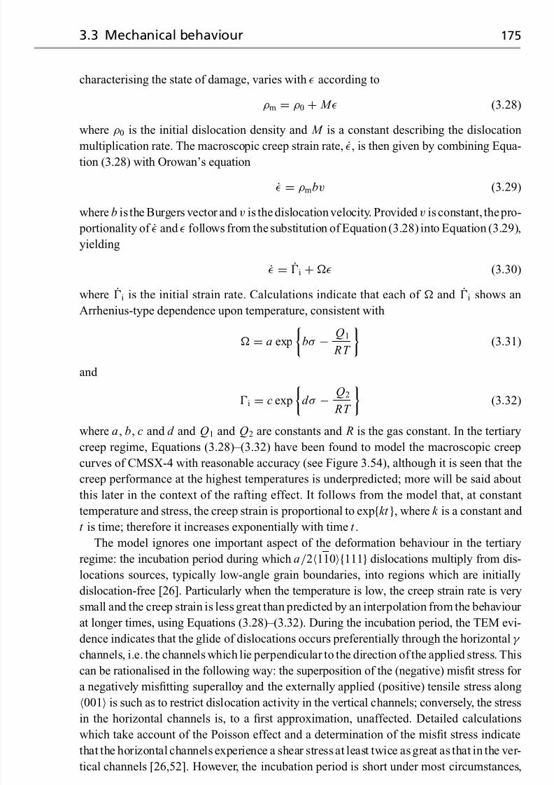
7/18/2019 The Superalloys Fundamentals and Applications
http://slidepdf.com/reader/full/the-superalloys-fundamentals-and-applications 193/389
3.3 Mechanical behaviour 175
characterising the state of damage, varies with according to
ρm = ρ0 + M (3.28)
where ρ0
is the initial dislocation density and M is a constant describing the dislocation
multiplication rate. The macroscopic creep strain rate, , is then given by combining Equa-
tion (3.28) with Orowan’s equation
= ρmbv (3.29)
where b is the Burgers vector and v is the dislocation velocity. Provided v is constant, thepro-
portionality of and follows from the substitution of Equation (3.28) into Equation (3.29),
yielding
=˙
i + (3.30)
where i is the initial strain rate. Calculations indicate that each of and i shows an
Arrhenius-type dependence upon temperature, consistent with
= a exp
bσ − Q1
RT
(3.31)
and
i
=c expd σ
−Q2
RT (3.32)
where a, b, c and d and Q1 and Q2 are constants and R is the gas constant. In the tertiary
creep regime, Equations (3.28)–(3.32) have been found to model the macroscopic creep
curves of CMSX-4 with reasonable accuracy (see Figure 3.54), although it is seen that the
creep performance at the highest temperatures is underpredicted; more will be said about
this later in the context of the rafting effect. It follows from the model that, at constant
temperature and stress, the creep strain is proportional to exp{kt }, where k is a constant and
t is time; therefore it increases exponentially with time t .
The model ignores one important aspect of the deformation behaviour in the tertiary
regime: the incubation period during which a/2110{111} dislocations multiply from dis-
locations sources, typically low-angle grain boundaries, into regions which are initially
dislocation-free [26]. Particularly when the temperature is low, the creep strain rate is very
small and the creep strain is less great than predicted by an interpolation from the behaviour
at longer times, using Equations (3.28)–(3.32). During the incubation period, the TEM evi-
dence indicates that the glide of dislocations occurs preferentially through the horizontal γ
channels, i.e. the channels which lie perpendicular to the direction of the applied stress. This
can be rationalised in the following way: the superposition of the (negative) misfit stress for
a negatively misfitting superalloy and the externally applied (positive) tensile stress along001 is such as to restrict dislocation activity in the vertical channels; conversely, the stress
in the horizontal channels is, to a first approximation, unaffected. Detailed calculations
which take account of the Poisson effect and a determination of the misfit stress indicate
that the horizontal channels experience a shear stress at least twice as great as that in the ver-
tical channels [26,52]. However, the incubation period is short under most circumstances,

7/18/2019 The Superalloys Fundamentals and Applications
http://slidepdf.com/reader/full/the-superalloys-fundamentals-and-applications 194/389
176 Single-crystal superalloys for blade applications
Fig. 3.54. A comparison of the creep data for the CMSX-4 single-crystal superalloy and the tertiary
creep model described by Equations (3.28)–(3.32). Note that the agreement between model and
experiment is generally good, except at high temperatures and low stresses. Data from refs. [45] and
[46].
and the equations given above can be used to describe the creep strain evolution in the
tertiary regime with reasonable accuracy.
B Primary creep regime
At low temperatures, and provided the applied stress is sufficiently high, 001-oriented
single-crystal superalloys undergo significant primary creep deformation. In Figure 3.55,creep curves for CMSX-4 are plotted at temperatures of 750 ◦C and 850 ◦C for specimens
of identical orientation and within a few degrees of 001. A number of observations can
be made. First, the primary creep strain increases with applied stress, with primary creep
eventually giving way to secondary creep soon after the knee of each curve; thus, significant
primary creep strain occurs only when the applied stress is greater than a critical threshold

7/18/2019 The Superalloys Fundamentals and Applications
http://slidepdf.com/reader/full/the-superalloys-fundamentals-and-applications 195/389
3.3 Mechanical behaviour 177
0
0
2
4
6
8
10
100 200 300
Time(h)
400 500
(a)
Time(h)
(b)
S t r a i n ( %
)
00 5 10 15 20
2
4
6
8
10
S t r a i n ( %
)
750 MPa 750 MPa
650 MPa
550 MPa
500 MPa
650 MPa
600 MPa
550 MPa 450 MPa
Fig. 3.55. Constant load creep data for CMSX-4 at low temperatures and high stresses, i.e. in the
primary creep regime. (a) 750 ◦C; (b) 850 ◦C.
3000
1
2
3
4
5
6
7
8
400 500 600 700 800
750 °C
850 °C
P r i m a r y c r e e p s
t r a i n ( % )
Stress (MPa)
Fig. 3.56. Plot of percentage primary creep strain against applied stress, confirming a threshold
stress of ∼500 MPa for operation of the primary creep mechanism.
value of about 500± 50 MPa; see Figure 3.56. Second, the transition from primary to
secondary creep occurs at a time which decreases as the applied stress increases; moreover,
further analysis reveals that the secondary creep rate scales in proportion to the primary
creep strain [46].
A characteristic of primary creep is a significant heterogeneity of slip. If the creep spec-
imen is cylindrical in shape, as is most usually the case, then after creep deformation thecross-section is found to be elliptical (see Figure 3.57), with the degree of ellipticity in-
creasing with the primary creep strain incurred. More significantly, careful characterisation
of the shape change and correlation of it with the specimen orientation indicates that the
macroscopic shape change is consistent with 112{111} deformation [46,53]. This obser-
vation was first made by Kear and co-workers in the late 1960s; they proposed a model for

7/18/2019 The Superalloys Fundamentals and Applications
http://slidepdf.com/reader/full/the-superalloys-fundamentals-and-applications 196/389
178 Single-crystal superalloys for blade applications
Fig. 3.57. Cross-section of a single-crystal creep specimen deformed in the primary creep regime
[53], illustrating the ellipticity caused by severe non-uniform deformation.
112{111} slip, which is supported by TEM studies, indicating that deformation occurs by
the movement of dislocation ribbons of net Burgers vector a112 [54]. These are able to
shear the γ precipitates in a conservative fashion. Since the Burgers vector of the ribbon is
large at a√
6, significant amounts of strain are accumulated as the ribbons sweep through
the γ /γ structure. If the applied stress is below the threshold for primary creep to oper-
ate, then the microscopic evidence shows that only dislocations of form a/2110{111} are
present, and that these reside in γ . This is very strong evidence that the a112 ribbons are
responsible for primary creep. Figure 3.58 shows a transmission electron micrograph of an
a112 ribbon in a creep-deformed TMS-82 single-crystal superalloy.
There has been considerable debate about the mechanism of formation of the a112dislocation ribbons, but it is now known to involve the reaction of a/2110{111} disloca-
tions in γ , which are dissociated into their Shockley partials. A typical reaction might then
be given by [55]
a/2[011] + a/2[101] → a/3[112] + a/6[112] (3.33)
If the applied stress is sufficient, the a/3[112] dislocation is able to enter the γ , leaving a
superlattice intrinsic stacking fault (SISF) behind it (see Figure 3.59(a)) and the remaining
a/6[112] at the γ /γ interface. Formation of the ribbon in γ then requires further reactions
between the a/2110{111}-type dislocations, such that the original a/6[112], a further
a/6[112] and eventually a second a/3[112], enter the γ ; see Figure 3.59(b). An anti-phase

7/18/2019 The Superalloys Fundamentals and Applications
http://slidepdf.com/reader/full/the-superalloys-fundamentals-and-applications 197/389
3.3 Mechanical behaviour 179
Fig. 3.58. TEM micrograph of an a112 ribbon in the single-crystal superalloy TMS-82, deformed
in creep at 750 ◦C and 750 MPa to 11% strain. The foil normal is {111}. (Courtesy of Cathie Rae.)
a /2[112]
a /3[112]a /6[112]
a /2[112]
a /3[112]
a /6[112]
a /3[112]
SISF
SISF SESFAPB
(a) (b)
γ ′γ ′
Fig. 3.59. Illustration of the mechanism of shearing of the γ by an a112 ribbon during primary
creep. An a/3[112] dislocation enters the γ , leaving a superlattice intrinsic stacking fault (SISF)
behind it, (a), leaving an a/6[112] partial at the γ /γ interface. In (b), the original a/6[112] and a
further a/6[112] have entered the γ , leaving a a/3[112] at the interface.
boundary (APB) then separates the two a/6[112] dislocations, and a superlattice extrinsic
stacking fault (SESF) the second a/6[112] and the final a/3[112]. Once formed, the ribbon
is able to glide through the γ precipitates in a glissile fashion. Ribbons intersecting a γ
precipitate cause it to be populated with stacking faults. The cessation of primary creep
occurs when the a112 dislocation ribbon is unable to glide conservatively through the
γ /γ structure, primarily due to the adsorption of a/2110{111} dislocation segments at
the γ /γ interfaces.
A consequence of the mechanism by which primary creep occurs in single-crystal su- peralloys is a considerable creep anisotropy. By this one means that the creep life is affected
very strongly by small changes in the orientation of the tensile axis with respect to the 001crystallographic axis. This was noted by MacKay and Maier [56], who plotted the variation
of the creep life of Mar-M247 single-crystals deformed at 760 ◦C on a 001/011/111standard triangle of the stereographic projection; see Figure 3.60. Misorientations of only
10◦ from 001 were found to have a profound effect on creep life, with orientations near

7/18/2019 The Superalloys Fundamentals and Applications
http://slidepdf.com/reader/full/the-superalloys-fundamentals-and-applications 198/389
180 Single-crystal superalloys for blade applications
Intermediate
IntermediateVery poor
Very good Good
Fig. 3.60. Variation of the performance of the Mar-M247 single-crystal superalloy deformed in
primary creep at 760 ◦C. Orientations near 011 have the shortest rupture lives, orientations near
111 the best, with 001 somewhere between. After ref. [56].
to the 001/011 boundary displaying very much better performance than those near to
the 001/111 one. While the details are beyond the scope of this book, these effects
arise because the movement of the a112 ribbon requires (i) sufficient densities of at least
two a/2110{111} families of dislocations in γ , to enable the nucleation of the disloca-
tion ribbons in accordance with the reaction given above, and (ii) sufficient resolved shear
stress for the propagation of the a112 ribbon. Thus conditions for both the nucleation
and the propagation of the ribbon must be satisfied if appreciable primary creep is to occur
[57]. Given this remarkably complex mechanism of primary creep deformation in single-
crystal superalloys, it is unsurprising that its extent is remarkably sensitive to the chemical
composition, with cobalt and rhenium in particular promoting primary creep and tantalum
suppressing it [55,57,58]; it seems plausible that stacking fault shear of γ is promoted by
HCP elements such as Co and Re since they lower the stacking fault energy in γ . This sug-
gestion is consistent with observations that primary creep in Co-containing single-crystal
superalloys is highly sensitive to orientation, with creep anisotropy being suppressed as the
Co content is reduced [58].
C Rafting regime
In the rafting regime, the γ /γ microstructure degrades rather quickly because thermally
activated processes are favoured strongly since the temperature is high. Two effects occur at
a very earlystage of deformation: (i) equilibrium interfacial dislocation networks form at the
γ /γ interfaces [59], and (ii) the γ particles coalesce by a process of directional coarsening

7/18/2019 The Superalloys Fundamentals and Applications
http://slidepdf.com/reader/full/the-superalloys-fundamentals-and-applications 199/389
3.3 Mechanical behaviour 181
Fig. 3.61. Rafted γ /γ structure in the CMSX-4 superalloy, deformed at 1150 ◦C and 100 MPa to
0.39% strain in 10 h [62].
known as the ‘rafting’ effect [49,60–62]. Figure 3.61 illustrates the rafted morphologyin the CMSX-4 superalloy after tensile creep loading to 0.39% strain in 10 h at 1150◦Cand 100 MPa [62]. The axis of loading lies in the plane of the micrograph in the vertical
direction; thus the normals to the broad faces of the rafts – which are plate-shaped in form –
lie perpendicular to the axis of loading. This is always found to be the case for negatively
misfitting alloys such as CMSX-4, into which category most commercially developed alloys
fall. When the misfit is positive, needle-shaped rafts are found whose long axes lie parallel
to the direction of loading. Changing the sign of the stress, i.e. compressive rather than
tensile loading, has an effect on the raft morphology which is equivalent to changing the
sign of the misfit.
The interfacial dislocation networks arise from a/2110{111} creep dislocations origi-
nating in the γ phase; these become captured by the γ /γ interfaces, and the networks are
formed by a series of dislocation reactions. The dislocations are primarily of edge character
with the extra half-planes in the γ phase if δ < 0. Thus by this mechanism the perfect
elastic coherency of the interfaces is lost and misfit stresses are relieved. Figure 3.62 is
taken from the work of Field, Pollock and co-workers [63], who have analysed the networks
in detail using TEM microscopy – this specimen was interrupted after 20 h with 0.5% creep
strain having been accumulated at 1093 ◦C. Note in particular the square configurationsof four dislocations of Burgers vector of a/2110 type; they are of edge character and
are thus efficient at relieving the misfit, but these segments have no shear stress resolved
on them – thus they must have been formed by reactions driven by reductions in misfit
and dislocation line energies. A model has been proposed by these authors which accounts
for their formation; see Figure 3.63. Initially, on a γ /γ interface which has [001] as its

7/18/2019 The Superalloys Fundamentals and Applications
http://slidepdf.com/reader/full/the-superalloys-fundamentals-and-applications 200/389
182 Single-crystal superalloys for blade applications
0101 1 0
1 1 0
1 1 0
1 0 1
1 1 0011
011
1 1 0
1 1 0
1 1 0
1 0 1
1 0 0
(b)(a)
200
1 1 0
0 2 0
Fig. 3.62. (a) TEM micrograph and (b) accompanying schematic interpretation of an experimental
single-crystal superalloy deformed to 0.5% creep strain in 20 h at 1093 ◦C, showing dislocation
networks at the γ /γ interfaces; arrows in (a) and (b) show equivalent positions. Foil normal {001},equivalent to the direction of loading. After ref. [63].
Fig. 3.63. Schematic representation of dislocation reactions leading to the formation of mismatch
accommodating nets on the (001) γ /γ interfaces during creep. After ref. [63].

7/18/2019 The Superalloys Fundamentals and Applications
http://slidepdf.com/reader/full/the-superalloys-fundamentals-and-applications 201/389
3.3 Mechanical behaviour 183
20
10
00 500 1000
( 2 % M o , 1 . 6
% R u
)
T M S - 7
5 ( + R
u )
T M S - 7
5
( 2 % M o , 0
% R u
)
T M S - 1 3 8
( 3 % M o , 2
% R u
)
T M S
- 7 5 ( + M o
)
( 3 % M o , 0
% R u
)
T M S - 1
6 2
( 4 % M o , 6
% R u
)
C r e e p s t r a
i n ( % )
Time (h)
Fig. 3.64. Creep curves of the superalloys TMS-75, TMS-75(+Ru), TMS-75(+Mo), TMS-138 and TMS-162 tested at 1100 ◦C and 137 MPa [64,65].
normal, slip-deposited dislocations form two perpendicular sets, for example of a/2[011]
dislocations, one resulting from slip on (111) and the other on (111). These can react to
form a single set with average line vector [100]. Further a/2110 dislocations resulting
from slip on the other two octahedral planes, (111) and (111), can then be knitted into the
net, consistent with reactions of the type [63]
a/2[101] − a/2[011] → a/2[110] (3.34a)
and
a/2[101] − a/2[110] → a/2[011] (3.34b)
or, alternatively,
a/2[101] + a/2[101] → a[100] (3.34c)
Thus it is clear that the equilibrium network can arise only when sufficient creep dislocations
have formed on all four of the {111}-type planes. Harada and co-workers have isolated astrong correlation between the dislocation density of the equilibrium network in single-
crystal superalloys of varying compositions and their creep performance under loading at
1100 ◦C and 137 MPa (see Figures 3.64 and 3.65), with the dislocation spacing being found
to be proportional to the logarithm of the minimum creep rate [64,65]. Use of this effect has
been made in designing TMS-162, which is one of the strongest single-crystal superalloys

7/18/2019 The Superalloys Fundamentals and Applications
http://slidepdf.com/reader/full/the-superalloys-fundamentals-and-applications 202/389
184 Single-crystal superalloys for blade applications
18
15
12
9
6
3
0
18
15
12
9
6
3
0
18
15
12
9
63
0
18
15
12
9
6
3
0
18
15
12
9
6
30
20 25 30 35 40 45 50 55 60 65 70 75 80 85 90
20 25 30 35 40 45 50 55 60 65 70 75 80 85 90
20 25 30 35 40 45 50 55 60 65 70 75 80 85 90
20 25 30 35 40 45 50 55 60 65 70 75 80 85 90
20 25 30 35 40 45 50 55 60 65 70 75 80 85 90
(a)
(b)
(c)
(d)
(e)
Dislocation spacing (nm)
O b s e r v a t i o n f r e q u e n c y
Fig. 3.65. Measurements of the equilibrium γ /γ dislocation spacings in (a) TMS-75(+Ru),
(b) TMS-75, (c) TMS-75(+Mo), (d) TMS-138 and (e) TMS-162 tested at 1100 ◦C and 137 MPa
[64,65]; taken with the data in Figure 3.64, a strong creep strengthening effect is confirmed when the
dislocation spacing is small.

7/18/2019 The Superalloys Fundamentals and Applications
http://slidepdf.com/reader/full/the-superalloys-fundamentals-and-applications 203/389
3.3 Mechanical behaviour 185
Fig. 3.66. SEM micrographs [62] of the CMSX-4 superalloy deformed at 950 ◦C. (a) γ /γ
microstructures after 280 h (0.07% strain) and 550 h (0.27% strain), with an applied stress of
185 MPa. (b) Microstructures after further heat treatment of 100, 300 and 600 h, with zero applied
stress.
to date (see Figure 1.17). Additions of Mo are critical to the superior creep performance
displayed, since the lattice misfit is reduced as the concentration of this element increases.The relaxation of interfacial misfit by the above mechanism is important since it is now
recognised that rafting occurs only once this has occurred [60–62]. Consider a negatively
misfitting alloy such as CMSX-4. The micromechanism of creep deformation in the ter-
tiary creep regime involves the multiplication of dislocations in γ , initially in the horizontal
channels for reasons discussed earlier; the relaxation of interfacial misfit thus occurs prefer-
entiallyon the γ /γ interfaces whosenormals lie parallel to thedirection of loading. Rafting
requires diffusion of γ -partitioning elements such as Cr, Re out of the vertical channels and
γ -partitioning elements such as Al, Ta into them; the evidence indicates that such mass
transport can occur only once the lattice misfit has become relaxed, probably because diffu-
sion occurs near or within the relaxed interfaces. The possibility of pipe diffusion of solutes
within thedislocation networks should notbe dismissed, although no direct evidencefor this
has been found as yet. The role of interfacial misfit relaxation in the rafting phenomenon
has been confirmed with experiments which have demonstrated that partially crept single
crystals continue to raft even after the externally applied load is removed [60,62]. More-
over, the kinetics of rafting are not slowed in any way by the removal of the stress field.
Figure 3.66 shows the results of experiments on CMSX-4 [62]. For deformation at 950 ◦C
and 185 MPa, an accumulated strain of about 0.1% is sufficient to relax the interfacial misfitand, thereafter, rafting without the externally applied load continues at the same rate as with
the load present.
A controversial question concerns the influence of the rafting effect on the creep capa-
bility of the single-crystal superalloys. Note (see Figure 3.61) that as many as ten or more γ
precipitates coalesce in the transverse direction; thus a fully developed raft is formed from
100 or more precipitates of total cross-sectional area equal to several hundreds of square

7/18/2019 The Superalloys Fundamentals and Applications
http://slidepdf.com/reader/full/the-superalloys-fundamentals-and-applications 204/389
186 Single-crystal superalloys for blade applications
10
5
00 100 200 300
Time (h)
S t r a i n ( % )
Interrupted
Rupture
C
DE
F
BA
Fig. 3.67. Constant load creep data for the CMSX-4 superalloy, deformed at 1150 ◦C and 100 MPa.
micrometres, since the rafts have a thickness equal to one γ particle. Extensive rafting leads
eventually to the inversion of the γ /γ structure such that the continuous, matrix phase is γ
rather than γ . Under these circumstances, rafting reduces the activity of the a/2110{111}dislocations in γ . This is supported by various pieces of evidence [66]. First, extrapolation
of the tertiary creep law to temperatures where rafting occurs leads to an underestimate
of the creep performance, particularly at small applied stresses when creep life is long;
see Figure 3.54(d). Second, in the rafting regime, fully developed rafts are found to have
formed at times equivalent to the onset of, or even before, the plateau observed in the creep
curves at these very high temperatures; see Figure 3.51(c). Thus rafting is at least partially
responsible for the creep-hardening effect which occurs initially and the creep plateau that
occurs thereafter. Third, there is considerable scatter in the creep rupture lives at these very
high temperatures (see Figure 3.67); however, the creep plateau is very reproducible. Final
rupture at these temperatures is associated with extensive creep cavitation at porosity intro-
duced either during the casting process into the interdendritic regions [67], or alternatively
at pores forming around TCP phases which precipitate at these elevated temperatures [66].
Cavitation is, however, restricted to those pores present in the vicinity of fracture surface(see Figure 3.68), and it is probable therefore that their formation is strain-controlled. Hot
isostatic pressing has, however, been found to increase the mean value of the rupture life
somewhat. However, more research is needed to clarify the reasons for the onset of the rapid
acceleration in creep strain rate leading to rupture, and the micromechanical deformation
modes which lead to the cutting of the rafted γ microstructure.

7/18/2019 The Superalloys Fundamentals and Applications
http://slidepdf.com/reader/full/the-superalloys-fundamentals-and-applications 205/389
3.3 Mechanical behaviour 187
10
8
6
4
2
00 5 10 15 20 25
Gauge length (mm)
(c)
(b)
F r a c t i o n o f p o r e s c a v i t a t e
d ( % )
(a)
Fig. 3.68. CMSX-4 creep testpiece interrupted after 2.2% strain after 200 h at 1150 ◦C and 100 MPa(see the creep curve marked ‘F’ in Figure 3.67). (a) Necked creep specimen at point of fracture.
(b) Micrograph of creep-cavitated casting porosity in necked region. (c) Variation of fraction of
pores cavitated as a function of distance along specimen, providing confirmation that cavitation is
restricted to the necked region.
3.3.2 Performance in fatigue
As for all metallic materials, the single-crystal superalloys are prone to fatigue failure due to
oscillating loads, at stresses which arenominally elastic. This is because plastic deformation
can occur in a very localised sense, typically near sites of stress concentration; this fatigue
damage is most often in the form of intense, localised slip with the dislocation activity
restricted to a small number of lattice planes [68]. This phenomenon is often referred to as
‘cyclic slip localisation’; particularly at temperatures of around 700 ◦C and when stresses
are high this encourages the formation of ‘persistent slip bands’ (PSBs) which shear the
γ particles [69]; see Figure 3.69. Fatigue initiation can always be traced to sites of stress
concentration, for example casting pores or machining marks. At higher temperatures and
when stresses are low, dislocation activity is restricted to the γ channels and cyclic slip
localisation is less intense; thus deformation is more homogeneous, but nonetheless limited to the most highly stressed {111} planes [70]; see Figure 3.70. Under these conditions,
fatigue initiation occurs at surface pits or cracks in the oxide films – and the life is improved
markedly if protective coatings (for example the aluminides) are used.
In practice, the environment experienced by the blading in service is very difficult to
replicateexactly in the laboratory. Consequently, reliance is placedon thecharacterisation of

7/18/2019 The Superalloys Fundamentals and Applications
http://slidepdf.com/reader/full/the-superalloys-fundamentals-and-applications 206/389
188 Single-crystal superalloys for blade applications
Fig. 3.69. Persistent slip bands in a 001-oriented single-crystal superalloy cycled at 700 ◦C [69],
in which the γ particles are sheared.
Fig. 3.70. Dislocation microstructure in the AM1 single-crystal superalloy deformed at 950 ◦C with
total = 1.27% and with R = 0 [70]. P is the projection of the loading axis. Dislocations are
localised at {001} interfaces, see arrows marked 1; {010} and {100} channels, see arrows marked 2,
are free of dislocations.
fatigue performanceunderconditions whichcanbeeasily controlled, forexample isothermal
tests under uniaxial load or strain control. The cyclic stress range, σ , is defined as σ max −σ min, where σ max and σ min are the maximum and minimum stresses seen during the cycle,
and the mean stress, σ mean, is 12(σ max + σ min). The R-ratio is defined as σ min/σ max, so that
R = −1 corresponds to fully reversed loading with σ max = −σ min and R = 0 corresponds

7/18/2019 The Superalloys Fundamentals and Applications
http://slidepdf.com/reader/full/the-superalloys-fundamentals-and-applications 207/389
3.3 Mechanical behaviour 189
1.25
1.00.90.8
0.70.6
0.5
0.4
0.3
0.2
0.1
T o t a l s t r a i n ( % )
103 104 105 106
N f (cycles)
⟨001⟩
⟨113⟩
⟨011⟩
⟨112⟩
⟨111⟩
Fig. 3.71. The orientation dependence of the strain-controlled LCF life of an experimental
single-crystal superalloy at 980 ◦C, for various values of the total strain range, total = 0.6 [71].
Axial load: K T = 1.0; frequency = 0.33 Hz.
to pure cyclic conditions with σ min = 0. Two distinct forms of fatigue failure are identified.Low-cycle fatigue (LCF) arises when the stress amplitude places the nominal stresses at
or beyond the elastic limit – failure occurs typically within 105 cycles, with a majority
of the fatigue life being spent in the propagation (rather than initiation) stage. From a
practical perspective, the driving force for LCF damage originates from abrupt changes in
loading due to engine start-up and stopping. Conversely, high-cycle fatigue (HCF) arises
from smaller stress amplitudes, typical of those imposed on the blading by vibrations or
resonance. In this case, the nominal stresses are always in the elastic regime, and the
majority of the fatigue life is spent in the initiation stage; failure occurs in excess of 10 5
cycles.
A Low-cycle fatigue
Under LCF testing conditions, which are often carried out under total strain control, it is
found that the fatigue performance depends very strongly on the orientation of the loading
axiswithrespect to thecrystallographic orientation, i.e.considerable anisotropyis displayed.
Figure 3.71 shows data due to Dalal, Thomas and Dardi [71], who measured the LCF
response of smooth, polished specimens of an experimental alloy (composition in wt%: Ni–6.8Al–13.8Mo–6W) at 980 ◦C, under total strain control and with R = 0. The logarithm
of the total strain range, total, is found to be inversely proportional to the logarithm of
the fatigue life, N f , for any given orientation. Of the three orientations at the corners of the
standard stereographic triangle, i.e. 001, 011 and 111, the 001 orientation displayed
the best performance and 111 the worst; all other orientations were between these two

7/18/2019 The Superalloys Fundamentals and Applications
http://slidepdf.com/reader/full/the-superalloys-fundamentals-and-applications 208/389
190 Single-crystal superalloys for blade applications
0
100
200
300
400
500
600
700
0.01 0.02 0.03 0.04 0.05 0.06 0.07 0.08 0.09
Strain,
S t r e s s , σ ( M
P a )
Fracture
Fracturestrain
0.1670.1160.1650.2560.219
∋
Fig. 3.72. Stress–strain curves for PWA1480 single-crystal testpieces, for various orientations taken
from the standard stereographic triangle [72].
limits. Thus the fatigue strength correlates strongly with the elastic modulus in the loading
direction – so that a direction such as 001, which is elastically soft, displays very much better properties than one which is stiff, such as 111. In fact, it can be shown that if one
plots the product total E hkl rather than total against N f , then the fatigue data collapse onto
a straight line. The term E hkl is the plane-specific elastic modulus along the loading axis.
These observations can be rationalised in the following way. Assuming for one moment
that the yield stresses in the 001 and 111 directions are equal, the elastic strain at yield
is smaller for a specimen tested along 111 on account of its greater stiffness; thus, under
total strain control, the plastic strain available to drive the fatigue process is correspondingly
greater, so that poorer properties are displayed. In fact, the yield stress shows a fair degree of
anisotropy; see, for example, the data of ref. [72] for the PWA1480 single-crystal superalloy
(Figure 3.72). Such experiments indicate that the yield stress along 001 is greater than
that along 111; the increment σ y can be in excess of 200 MPa; under total strain control,
the plastic strain along 001 is reduced by a factor σ y/ E 001 due to this effect, giving
further justification to the superior properties along 001. Under load control, the situation
is more complicated. The low modulus along 001 might at first be expected to result in
large strains and poor fatigue life, but this is not observed in practice. Clearly, under load-
controlled conditions one must be relying on the larger flow stress along that direction, or,
alternatively, the life is limited by stress concentrations which behave in a strain-controlled manner.
Under LCF conditions, the cyclic stress–strain hysteresis loops show a number of in-
teresting characteristics. First, the width of the loops is larger when high inelastic strains
are imposed, which occurs for the stiffest orientations. See, for example, Figure 3.73 [71],
for the case of R = 0. Second, a considerable degree of tension–compression yield stress

7/18/2019 The Superalloys Fundamentals and Applications
http://slidepdf.com/reader/full/the-superalloys-fundamentals-and-applications 209/389
3.3 Mechanical behaviour 191
550
275
−275
−550
0 0.3
⟨001⟩
(%)
0.6
E ⟨001⟩ = 99.3 GPa
550
275
−275
−550
0 0.3 0.6
⟨113⟩
E ⟨113⟩ = 129.6 GPa
550
275
−275
−550
0
0.3 0.6
⟨011⟩
σ
( M P a
)
σ ( M
P a
)
σ ( M
P a
)
E ⟨001⟩ = 169.6 GPa
σ
( M P a
)
550
275
−275
−550
0
0.3 0.6
⟨111⟩
E ⟨111⟩ = 226.1 GPa
σ
( M P a
)
550
275
−275
−550
0
0.3 0.6
⟨112⟩
E ⟨112⟩ = 188.9 GPa
∋ (%) ∋
(%) ∋
(%) ∋ (%)
∋
Fig. 3.73. Effect of crystallographic orientation on fatigue hysteresis loops for an experimental
single-crystal superalloy at 980 ◦C and with total = 0.6, R = 0 [71].
asymmetry is observed for 001 orientations, with the yield stress in tension exceeding that
in compression; Gabb et al. [73] report for Rene N4 values of 956 MPa and 818MPa for tension and compression, respectively, at 760 ◦C. Interestingly, along 011 the yield stress
is greater in compression than in tension – the values reported are 748MPa and 905MPa
for tension and compression, respectively; along 111 little anisotropy was observed –
817 MPa and 842 MPa, respectively. Finally, the cyclic stress–strain curves show a consid-
erable strain-softening response [74] – the values of σ max and σ min decline during the test
consistent with a creep contribution inducing damage into the material. The experiments
by Mughrabi et al. on the CMSX-6 superalloy (see Figure 3.74) indicate that the strain
softening is most pronounced at higher temperatures, when the γ /γ structure evolves via
the rafting effect. These same workers have demonstrated that prestraining in tension, which
induces rafts aligned normal to the stress axis, weakens the material in fatigue; conversely,
prestraining in compression strengthens it.
As expected, the LCF life decreases quickly with increasing temperature. Figure 3.75
shows data [75] for the CMSX-4 single-crystal superalloy, measured under load control,
with R = 0. One can see that no distinct endurance limit is displayed. Extensive shear
banding and PSBs are found in the vicinity of the fracture surface; see Figure 3.76.
B High-cycle fatigue
The natural resonant vibratory frequencies of single-crystal turbine blading range from a
few to several thousand hertz. Consequently, if the excitation frequencies due to turbulent
flow around the aerofoil are in this range, then high-cycle fatigue (HCF) failure will occur.
HCF loads are superimposed on the steady-state mean stresses arising from centrifugal

7/18/2019 The Superalloys Fundamentals and Applications
http://slidepdf.com/reader/full/the-superalloys-fundamentals-and-applications 210/389
192 Single-crystal superalloys for blade applications
600
300
−300
−600
0
1100 °C
1050 °C
1000 °C
950 °C
σ ( M
P a )
Number of cycles
Fig. 3.74. Isothermal, cyclic fatigue
deformation data for the CMSX-6 superalloy
[74], showing the tensile and compressive
peak stresses versus cycle number. Total
strain range total = 10−2; fully reversed
conditions.
1400
1200
1000
800
600
400
200
0103 104 105 106
Cycles to failure
750 °C
850 °C
950 °C
1050 °C
M a x i m u m
s t r e s s ( M P a )
Fig. 3.75. Load control, LCF fatigue data [75] for the uncoated, second-generation superalloy
CMSX-4 at various temperatures, with R = 0.
loading of the blade and thermal loads from thermal gradients set up by the action of
the hot gas and the cooling air passing through the blading. Clearly, one then expects
the HCF performance to depend on the R-ratio, and a considerable interaction of fatigue
and creep damage mechanisms might be anticipated when the temperature is high and
as R → 1.
Recently, Wright and co-workers [76] have completed elegant and careful work whichsheds light on theeffects occurring duringHCF loading. Load-controlled testing was carried
out at 1038 ◦C on 001-oriented single-crystal specimens of PWA1484 protected with a
platinum aluminide coating. A first set of tests werecarried out at 59 Hz for R-ratios of −1.0,
−0.33, 0.1, 0.5, 0.8 and 1.0; obviously, when R = 1.0 there is no alternating component so
that, in that limiting case, one is executing a constant load creep test. A second set of tests

7/18/2019 The Superalloys Fundamentals and Applications
http://slidepdf.com/reader/full/the-superalloys-fundamentals-and-applications 211/389
3.3 Mechanical behaviour 193
Fig. 3.76. Intense shear banding and persistent slip bands near the fracture surface of a CMSX-4
testpiece, cycled under constant load control at 850 ◦C, R = 0 and with σ max = 760 MPa [75].
were carried out at R = −1.0 and R = 0.1 at a range of frequencies from 59 Hz to 900Hz.
The results for the fatigue life, N f , are plotted against the stress range, σ , on a conventional
σ – N diagram (Figure 3.77(a)); for each R-ratio the Coffin–Manson relationship is obeyed. No evidence of an endurance limit was found. Moreover, the fatigue capability is seen to
decrease, and the slope of the curve is steeper as R → 1. In Figure 3.77(b), the data are
plotted instead as σ mean against time to failure. Here, the data for the higher R-ratios (0.5, 0.8
and 1.0) collapse along a single line defined by the creep rupture capability. This implies that
life is independent of the alternating stress σ ; thus the dominant mode of damage is creep.
The data for lower R-ratios fall at lower times, implying that a fatigue mode is operative
in that regime. The data at varying frequencies allow the fatigue and creep components
to be further distinguished. When R= −
1 the results were found to be independent of
frequency for the range examined (see Figure 3.78(a)); this implies that a time-independent
fatigue process is occurring at low mean stresses. At higher mean stresses, corresponding to
R = 0.1, life is larger at the higher frequencies for any given σ ; see Figure 3.78(b). This
is because the failure depends more heavily upon the creep component which is time- rather
than cycle-dependent. The characteristics of the fracture surfaces were consistent with this
interpretation. At low mean stresses, corresponding to R = −1, failure was initiated either
internally at pores, carbides or eutectic γ , and crystallographic facets could be identified
consistent with a fatigue mode of damage accumulation. At higher R-ratios, the appearance
of the fracture surface resembled that of a creep rupture failure; it was rough with multiplesurface cracking and a degree of necking was evident.
Wright and co-workers [76] displayed their results on the so-called Goodman diagram,
on which the stress range, σ , is plotted against the mean stress, σ mean, for a constant
HCF capability. Figure 3.79 shows a typical diagram for 107 cycles to failure; the num-
bers correspond to the percentage creep damage determined from a creep–fatigue damage

7/18/2019 The Superalloys Fundamentals and Applications
http://slidepdf.com/reader/full/the-superalloys-fundamentals-and-applications 212/389
194 Single-crystal superalloys for blade applications
Fig. 3.77. HCF data for coated PW1484 at 1038 ◦C at 59 Hz, showing the effect of R-ratio:
(a) conventional σ – N curve, and (b) plot of mean stress versus time to failure [76].
mechanics model to which the data were fitted. For R > 0 one can see that creep mode
becomes significant.
3.4 Turbine blading: design of its size and shape
The previous sections in this chapter have been concerned with the processing of tur-
bine blade aerofoils by investment casting, with the metallurgical principles controlling
the optimum superalloy compositions and with the mechanical behaviour observed during

7/18/2019 The Superalloys Fundamentals and Applications
http://slidepdf.com/reader/full/the-superalloys-fundamentals-and-applications 213/389
3.4 Turbine blading: design of size and shape 195
Fig. 3.78. HCF data for coated PW1484 at 1038 ◦C showing the effect of frequency: (a) R = −1
and (b) R
=0.1 [76].
service. Until now, the factors influencing the shape and geometry of the aerofoil have been
largely ignored; these are dealt with in this section. It turns out that the relevant consider-
ations depend largely on the laws of aerodynamics, fluid mechanics and thermodynamics
[77,78].
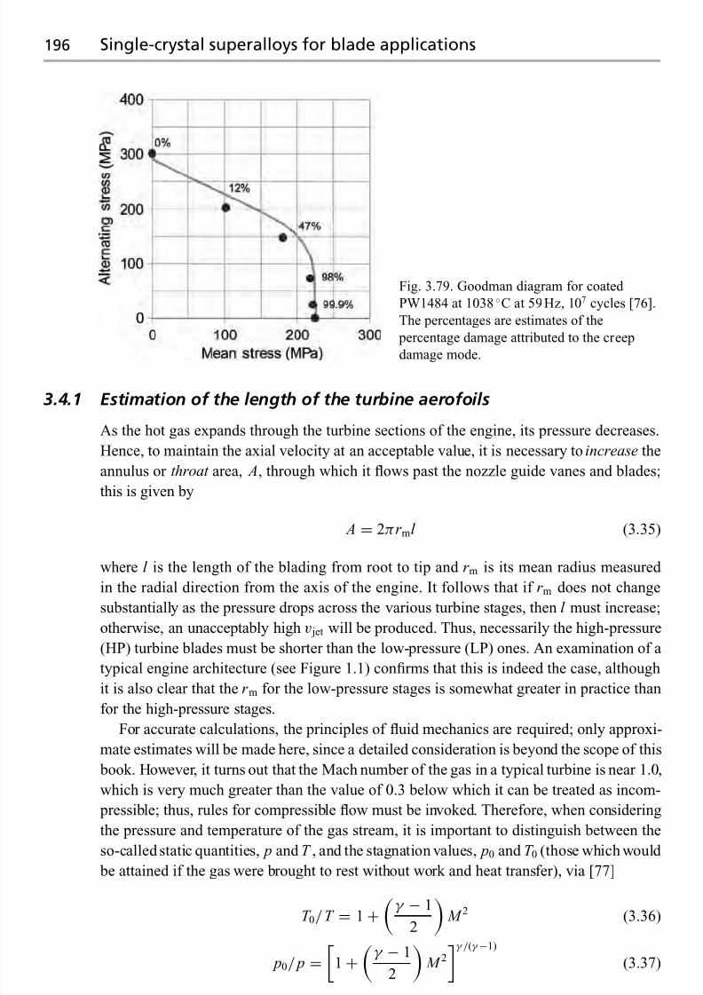
7/18/2019 The Superalloys Fundamentals and Applications
http://slidepdf.com/reader/full/the-superalloys-fundamentals-and-applications 214/389
196 Single-crystal superalloys for blade applications
Fig. 3.79. Goodman diagram for coated
PW1484 at 1038 ◦C at 59Hz, 107 cycles [76].
The percentages are estimates of the
percentage damage attributed to the creep
damage mode.
3.4.1 Estimation of the length of the turbine aerofoils
As the hot gas expands through the turbine sections of the engine, its pressure decreases.
Hence, to maintain the axial velocity at an acceptable value, it is necessary to increase the
annulus or throat area, A, through which it flows past the nozzle guide vanes and blades;
this is given by
A = 2πr ml (3.35)
where l is the length of the blading from root to tip and r m is its mean radius measured
in the radial direction from the axis of the engine. It follows that if r m does not change
substantially as the pressure drops across the various turbine stages, then l must increase;
otherwise, an unacceptably high v jet will be produced. Thus, necessarily the high-pressure
(HP) turbine blades must be shorter than the low-pressure (LP) ones. An examination of a
typical engine architecture (see Figure 1.1) confirms that this is indeed the case, although
it is also clear that the r m for the low-pressure stages is somewhat greater in practice thanfor the high-pressure stages.
For accurate calculations, the principles of fluid mechanics are required; only approxi-
mate estimates will be made here, since a detailed consideration is beyond the scope of this
book. However, it turns out that the Mach number of the gas in a typical turbine is near 1.0,
which is very much greater than the value of 0.3 below which it can be treated as incom-
pressible; thus, rules for compressible flow must be invoked. Therefore, when considering
the pressure and temperature of the gas stream, it is important to distinguish between the
so-called static quantities, p and T , and the stagnation values, p0 and T 0 (those which would
be attained if the gas were brought to rest without work and heat transfer), via [77]
T 0/ T = 1+
γ − 1
2
M 2 (3.36)
p0/ p =
1 +
γ − 1
2
M 2
γ /(γ −1)
(3.37)

7/18/2019 The Superalloys Fundamentals and Applications
http://slidepdf.com/reader/full/the-superalloys-fundamentals-and-applications 215/389
3.4 Turbine blading: design of size and shape 197
where M is the local Mach number, the ratio of the velocity, V , to the speed of sound given
by√
γ RT . As in Chapter 1, γ is the ratio of the specific heats at constant pressure and
constant temperature, R is the gas constant and T is absolute temperature.
In order to determine the rate of mass flow, m, through a section of area A, one must
consider the combination
m/ A = ρV (3.38)
where ρ is the density of the gas streamand V is itsvelocity. Conservation of energy requires
mc p T + mV 2/2 = mc p T 0 (3.39)
where, upon rearranging, one has V =
2c p(T 0 − T ). Assuming isentropic flow such that
ρ
=C T 1/(γ −1), where C is a constant given by C
=ρ
γ −10 /T
γ −10 , one has
m/ A = C T 1/(1−γ )
2c p(T 0 − T ) (3.40)
After some algebraic manipulation, one can show that the dimensionless mass flow rate per
unit area, Q, defined by the quantity m
c p T 0/ Ap0, is given by [77]
Q = m
c p T 0
Ap0
= γ √ γ − 1
M
1+
γ − 1
2
M 2
−(γ +1)/(2(γ −1))
(3.41)
One can see from the right-hand side that Q is constant for any given γ and M . Thus, this
equation describes how the throat area, A, must change as p0 and T 0 alter. The variationof Q with Mach number, M , is given in Figure 3.80, for the case γ = 1.4. It is found that
the flow rate is a maximum at a Mach number of 1, when Q = 1.281; at this point, the
cross-section, or nozzle, is said to be ‘choked’. For the turbine sections in a jet engine,
this is usually a good assumption. It can be shown that, close to sonic velocity, very small
changes in A produce largevariationsin the Mach number and pressure.Note that it has been
assumed that the flow is one-dimensional and adiabatic. Provided that these are reasonable
assumptions, Figure 3.80 can be used to determine A if estimates of the other quantities
in the expression for Q are known. To a first approximation, one can take estimates of the
pressure and temperature of the gas stream from the ideal thermodynamic cycle described
in Chapter 1; this turns out to be not a bad assumption.
These considerations demonstrate that as p0 decreases, A must increase – so the blades
must get longer. The effect of the corresponding temperature drop is found to be rather
less important in influencing A. This explains why the low-pressure blades of a gas turbine
engine are very much longer than the high-pressure ones.
Example calculation
A high-pressure (HP) turbine stage passes a massflow of200 kg/s. If thestagnation pressure
and temperature of the gas stream are taken as 1800kPa and 1450 K, respectively, choose
an appropriate annulus area, A. Assume that the flow is occurring close to Mach 1, so that
the cross-section can be assumed to be choked. Hence, if the mean radius of the stage is to
be 0.5 m, determine the length of the turbine blading. Take c p = 1000J/(kg K).

7/18/2019 The Superalloys Fundamentals and Applications
http://slidepdf.com/reader/full/the-superalloys-fundamentals-and-applications 216/389
198 Single-crystal superalloys for blade applications
1.2
1
0.8
0.6
0.4
0.2
0 0.5 1 1.5 2 2.5 3
T / T 0
m √ c p T 0A p 0
p / p 0
ρ / ρ0
Mach number
Fig. 3.80. Variation of the non-dimensional flow rate, m
c p T 0/ Ap0, with Mach number, M , for a
perfect gas with γ = 1.4, flowing through a uniform orifice. Also shown are the ratios of static to
stagnation values of pressure, density and temperature. Adapted from ref. [77].
Answer At choking conditions, it follows that
Q = m
c p T 0
Ap0
= 1.281
so that
A = 200√
1000 × 1450
1.281× 1800 × 103= 0.1044m2 = 2πr ml
If r m = 0.5 m, it follows that l = 33mm.
3.4.2 Choice of mean radius for turbine blading
The function of the turbine blading is to extract mechanical work from the gas stream, and
to do this as efficiently as possible. To a good approximation, the gas flow after exit from
the nozzle guide vanes can be assumed to be axial; but, after interaction with the turbine
blading, there is a significant tangential component.

7/18/2019 The Superalloys Fundamentals and Applications
http://slidepdf.com/reader/full/the-superalloys-fundamentals-and-applications 217/389
3.4 Turbine blading: design of size and shape 199
Suppose that the flow enters at radius r (which remains unchanged) with tangential
velocity V θ 1 and that it leaves with a value equal to V θ 2. The torque, T , required for this to
occur is equal to the rate of change of angular momentum, and the power extracted, W , is
the torque times the angular velocity, ; hence,
W = T = mr m(V θ 2 − V θ 1) = mU m(V θ 2 − V θ 1) (3.42)
where U m is the speed at the mean blade radius and the product U m(V θ 2 − V θ 1) is known
as the stagnation enthalpy; it is given the symbol h0.
Equation (3.42) is one form of the Euler equation. It can be written in non-dimensional
form as
h0
U 2m= V θ 2
U m− V θ 1
U m= c pT
U 2m(3.43)
where T is the temperature drop across the stage. Extensive experimentation by aero-dynamicists on turbine systems has shown that the non-dimensional work coefficient,
c pT /U 2m, must not exceed ∼2, for satisfactory performance of the aerofoils.
Example calculation
A row of turbine blades is spinning at 6000 rev/min, and a temperature of 250 K is dropped
across the stage. Estimate the mean radius, r m, at which the row should be placed, for
optimum efficiency. Take c p =
1000J/(kg K) as before.
Answer From the data given, = 100rev/s and the core turbine work, h0 ∼ c pT ,
is 250kJ/kg. Now for an efficient turbine
c pT
U 2m∼ 2
hence U m = 350 m/s and therefore r m = U m/(2π ) is approximately 0.56 m. It follows
that if ω drops to half of its value, to 50 revs/s, r m must be doubled to 1.1 m. Conversely, if
the temperature drop is reduced by a factor of 2 to 125 K, then r m
is reduced by a factor of √ 2 to 0.40m.
This result has some severe consequences for the design of the low-pressure (LP) turbine
for a civil turbofan engine such as the Rolls-Royce Trent 800 or General Electric GE90.
Since there is a need to restrict the tip speed of the fan blade to values not greatly exceeding
the speed of sound, the LP shaft speed is relatively low – about 3000rev/min – and therefore
approximately one-third of the speed of the HP spool. Thus, given the considerations so
far, r m should ideally be made very large to return U m and the work coefficient, c pT /U 2m,
to acceptable values for optimum aerodynamic performance; however, calculations will
confirm that this becomes difficult as the required r m is then large enough to cause problemswith the flow of the bypass air past the engine core.
In practice, this problem is solved by building a multistage LP turbine. Across each
stage, a relatively small T is dropped, thus restricting the work extracted. The penalty
incurred, unfortunately, is greater weight – since the amount of turbomachinery required is
then significantly increased – and greater manufacturing and maintenance costs. All large

7/18/2019 The Superalloys Fundamentals and Applications
http://slidepdf.com/reader/full/the-superalloys-fundamentals-and-applications 218/389
200 Single-crystal superalloys for blade applications
civil turbofans suffer from this difficulty. For example, the three-spool Trent 800 has single-
stage HP and intermediate pressure (IP) turbines, but a five-stage LP turbine. The two-spool
GE90 is built with a two-stage HP turbine and a six-stage LP turbine. For Pratt & Whitney’s
two-spool PW4084, two HP stages are used, but a seven-stage LP turbine is required.
3.4.3 Estimation of exit angle from blade cross-section
The turbine consists of alternating rows of stationary guide vanes (stators) and blades
(rotors); see Figure 3.81. The blades move in the tangential direction at a speed U m, which,
to a good approximation, is not very different from the local speed of sound. The function of
the guide vanes is to remove the tangential component of the gas flow; the blades introduce
this asa consequence of extracting work fromthe gas stream. Since it isnot effective to allow
the high-pressure gas exiting from the combustion chamber to undergo a single expansionacross a single stage, the alternating rows of stationary vanes and moving blades facilitate
a series of smaller expansions, which can be used efficiently [79].
In practice, the flow around the turbine blading is unsteady, and a full mathematical
treatment is very complicated. However, it is helpful to consider the relative frame of
reference local to the moving blades and the absolute reference frame pertinent to the
stationary guide vanes. In the relative frame of reference, it has been found that the flow
is steady enough to make calculations of sufficient accuracy for practical purposes. The
situation is then as depicted in Figure 3.82. The gas is assumed to have an axial component
of velocity given by V x . The gas approaches the first row of stators with absolute velocity
V abs1 at an angle αabs
1 to the axial; its tangential component is thus V x tan αabs1 . After exit from
the guide vane, the absolute velocity, V abs2 , has increased, as has the tangential component,
which is now given by V x tan αabs2 . Note that the absolute velocity of the gas exiting the
guide vane is greater in the absolute frame than in the relative one; the converse is true for
the gas exiting the blading – the angle αrel3 is somewhat bigger than αabs
3 .
These considerations of so-called velocity triangles allow a first estimate of the shape of
the trailing edge of the turbine blading, as the following example will demonstrate.
Example calculation
A first-row HP turbine stage is operating in the gas stream of a gas turbine engine. Estimate
the flow direction which the gas should take out of the blading if the mean velocity, U m, is
set at twice the axial velocity of the gas stream.
Answer The stagnation enthalpy, h0, is given by
h0 = U mV xtan
αrel3
− tan
αrel2
= U mV xtan
αabs2
− tan
αabs3
Assuming that the velocity of the gas relative to the blading is perfectly axial on exit from
the nozzle guide vane, tan{αrel2 } = 0. With h0/U 2m = 2 and U m = 2V x as given, then
tan{αrel3 } = 4 so that αrel
3 = 76◦.

7/18/2019 The Superalloys Fundamentals and Applications
http://slidepdf.com/reader/full/the-superalloys-fundamentals-and-applications 219/389
3.4 Turbine blading: design of size and shape 201
Fig. 3.81. Photographs of turbine components for the CFM-56 engine: (a) guide vanes (stators) in
low-pressure turbine section, and (b) spool of high-pressure turbine blading.

7/18/2019 The Superalloys Fundamentals and Applications
http://slidepdf.com/reader/full/the-superalloys-fundamentals-and-applications 220/389
202 Appendix
Stator
Rotor
α1
α2
α3
V 1
V 2
V 3
U
U
U
U Tangential
θ
x Axial
Blade
speed
Absolute velocityinto rotor
Absolute velocityout of rotor
Relative velocityinto rotor
Relative velocityout of rotor
V 3rel
V 2rel
α3rel
α2rel
Fig. 3.82. Stage of an axial flow turbine, showing nozzle guide vanes (stators) and blading (rotors)
in cross-section [77].
A
2R 2R
Ah
+
v dt
(a) (b)
Fig. 3.83. Approximation of the dendrite tip as a cylinder with a hemispherical tip. (a) The
cross-section of the cylinder, A = π R2, determines the volume which grows in time d t . The surface
area of the hemispherical cap, Ah
=2π R2, determines the amount of radial solute diffusion. (b) The
size of the dendrite in relation to the cylinder. After ref. [22].
Appendix. Growth of an isolated dendrite, using hemispherical
needle approximation
The tip of a dendrite moving at a velocity v can be approximated as a cylinder with a
hemispherical capof radius R; seeFigure 3.83. This allows some important factors affecting
growth to be accounted for.
The cross-section of the cylinder, A = π R2, determines the volume which grows in time
d t ; this is responsible for the rejection of solute into the melt. Likewise, the surface area of
the cap, Ah = 2π R2, determines the amount of radial solute diffusion. The flux, J 1, due to
solute rejection and the flux, J 2, due to diffusion in the liquid ahead of the tip are given by
J 1 = Av(c∗l − c∗s ) J 2 = − D Ah
d c
d r
r = R
(A1)
and, under steady-state conditions, these two fluxes must be equal.

7/18/2019 The Superalloys Fundamentals and Applications
http://slidepdf.com/reader/full/the-superalloys-fundamentals-and-applications 221/389
Questions 203
The concentration gradient at the tip can be approximated by the value appropriate for a
growing sphere, evolving under steady-state conditions:
d c
d r
r = R = −c∗l − c0
R
(A2)
This can be proved by finding the solution to Laplace’s equation in spherical coordinates:
d
d r
r 2
d c
d r
= 0 (A3)
by satisfying the boundary conditions and by evaluating the first derivative at r = R.
Combining the various expressions, one has
v R
2 D =
c∗l − c0
c∗l − c∗s(A4)
where the term on the right-hand side is known as the supersaturation, . At constant ,
the result predicts that the velocity, v, is inversely proportional to the dendrite tip radius, R.
Note that the expression for the flux at the dendrite tip is onlyapproximate, sinceLaplace’s
equation was used. A rigorous analysis yields the Ivantsov solution, see ref. [22], but it can
be shown that the approximation given is accurate in the limit ∼ 0.
Questions3.1 The materials used for high-pressure turbine blade aerofoils are often referred to
as single-crystal superalloys. Explain why the use of the term ‘single-crystal’ is
disingenuous.
3.2 How might the (a) axial and (b) transverse temperature gradients compare during the
investment casting of a typical high-pressure blade for (i) an aeroengine and (ii) an
industrial gas turbine?
3.3 During investment casting of hollow turbine blading, platinum pins are sometimes
used to keep the internal ceramic and shell from moving relative to each other. These
are expensive: why does one bother with them?3.4 During solidification of a single-crystal alloy, the variation of fraction solid with
temperature is an important consideration. Sketch the variation which might be ex-
pected assuming (i) equilibrium freezing conditions and (ii) Scheil freezing with no
back-diffusion.
In order to assess whether back-diffusion is important, it has been suggested that
one consider the parameter
α
= Dst f
L2
where Ds is the diffusion coefficient in the solidifying phase, L is a character-
istic distance equivalent to the dendrite arm spacing and t f is the solidification
time (G /(vT )), where T is the solidification range. Using appropriate val-
ues of the G , v and T for directional solidification, estimate the solidification
time, t f .

7/18/2019 The Superalloys Fundamentals and Applications
http://slidepdf.com/reader/full/the-superalloys-fundamentals-and-applications 222/389
204 Questions
In order to determine whether back-diffusion is important, one should consider
the Clyne–Kurz parameter, α, where
α
=α 1
−exp−
1
α− 0.5exp−
1
2α
Note that α = 0 for Scheil solidification and α = 0.5 for equilibrium solidifica-
tion given by the lever rule. Using this expression, and making estimates for the
various parameters, determine whether back-diffusion is likely to be an important
consideration for these alloys.
3.5 Investment cast components often exhibit dramatic changes in cross-section. How
would one expect the spacing of isotherms to change when the cross-section of the
casting increases in this way? Rationalise the observation that freckle chainsare often
found near re-entrant features, such as shrouds and platforms.3.6 The preferred growth direction of a single-crystal superalloy is 100. Why?
3.7 Consider a typical Bridgeman arrangement for the casting of directionally solidified
components. What would be the effect of increasing the withdrawal velocity on
the temperature gradient at the liquidus? What is the disadvantage of a more rapid
withdrawal rate?
3.8 The following defects can occur during the casting of single-crystal components:
(i) high-angle grain boundaries, (ii) freckles and (iii) spurious grains. What is meant
by these terms? Give a brief explanation of the origin of each effect.
3.9 Various empirical relationships have been derived to describe the susceptibility of a
single-crystal superalloy to freckling. Expressions which have been proposed for a
freckling index, F , include
W + Re
Taor
W + 1.2Re
Ta + 1.5Hf + 0.5Mo− 0.5Ti
where the alloy compositions are input in wt%. Is there any physical basis underlying
their use? On the basis of the known mechanism of freckling, is the value of F
required to be small or large if defect-free castings are to be produced?
Using typical compositions for the superalloys (wt%), rank the susceptibility of
the first-, second- and third-generation alloys to freckle formation. Are your find-
ings consistent with the observation that the later generations are more freckle
prone?
Many alloy developers are considering additions of Ru to single-crystal superal-
loys. How should you modify the expression for F to account for the presence of this
element?
3.10 Find a good estimate of the thermal expansion coefficient of a typical single-crystal
superalloy used for a turbine aerofoil. Use this to estimate the shrinkage strain ex- pected when a casting cools to ambient temperature. What are the implications of
your findings, particularly for the design of the ceramic mould?
3.11 In recent years, attempts have been made to improve the thermal gradients typical
of an investment casting furnace. Developments such as liquid metal cooling (LMC)
and gas cooled casting (GCC) have been made. It has proven possible to reduce the

7/18/2019 The Superalloys Fundamentals and Applications
http://slidepdf.com/reader/full/the-superalloys-fundamentals-and-applications 223/389
Questions 205
primary dendrite arm spacing by about a factor of 2, from about 500μ m to 250 μ m.
How much shorter might then one expect the heat treatment time to be?
3.12 During directional solidification, heat is lost by (i) conduction to the chill through the
solidified portion of the ingot, and (ii) radiation to the surroundings via the emissivity
of the ceramic shell. Since these two contributions to the total heat loss, qtotal, are
additive, one has
qtotal = (hc + hr )(T − T 0), where hc =κ
L, hr =
σ (T 4 − αT 4)
(T − T 0)
where hr and hc are the radiative and conductive heat transfer coefficients, respec-
tively, and L is the length of the solidified portion of the casting. The constants and α
can be taken tobe 0.5.The Stefan–Boltzmannconstant σ
=5.67
×10−8 W/(m2 K 4).
Using reasonable values for κ, T and T 0, find the length of the solidified ingotat which the contributions to the heat loss from radiation and conduction are equal.
Hence show that, for a casting of any significant size, the majority of heat is lost by
radiation rather than by conduction.
3.13 After casting, components fabricated from single-crystal superalloys undergo a com-
plicated heat treatment designed to remove the microsegregation inherited from the
casting process. What would be the implications of not doing this?
3.14 For the single-crystal superalloy CMSX-4, the density of the liquid phase has been
measured to be 7.754g/cm3 at the melting point; it varies at a rate−
0.0009g/cm3 K
with temperature. Using this information, compare the freckling susceptibility of
the first-, second- and third-generation single-crystal superalloys Rene N4, CMSX-4
and CMSX-10. Do this by evaluating the differences in density between the liquid
at the melting point and that at a (lower) temperature at which solidification is 10%
completed. Use the Thermo-Calc software for making the equilibrium calculations.
What assumptions have been invoked?
Hence show that there is a tendency for the later generations of single-crystal
alloys to be prone to freckling.
3.15 Demonstrate that, for a binary phase diagram which possesses a liquidus slope of m, the undercooling, T , experienced by an alloy of mean composition c0 at a
supersaturation close to zero is given by
T ∼ mc0(1− k )
where k is thesolid/liquidpartitioningcoefficient. (Hint:Note that T = (c∗l − c0)m,
where c∗l = c0/(1 − (1− k )). The factor c∗l is the solute concentration in the liquid
at the solid/liquid interface.)
3.16 The alloy development programmes have contributed greatly to the improved creepstrengths of modern single-crystal superalloy materials. What have been the physical
principles which underpin this work?
3.17 Harada has carried out an elegant experiment in which the creep lifetimes of the
single-crystal superalloys TMS-75 and TMS-82+ were measured as a function of
the fraction of the γ phase present. The alloys were cast such that the compositions

7/18/2019 The Superalloys Fundamentals and Applications
http://slidepdf.com/reader/full/the-superalloys-fundamentals-and-applications 224/389
206 Questions
of the γ and γ phases were on a common tie-line, so that the phase compositions
remain invariant. The results from this experiment are given in Figure 3.29.
What do the results from this experiment tell us about the creep deformation
behaviour of superalloys? Why is the maximum creep resistance not imparted at a
50% fraction of γ ?3.18 When designing a new single-crystal superalloy composition, what are the properties
which are desirable? Give examples of trade-offs between the various properties that
are required.
3.19 In Figure 3.33, the evolution of the lattice misfit, δ, in the single-crystal superal-
loy SC16 is plotted during temperature decrements of 100 ◦C between 1200 ◦C and
800 ◦C. It is found that, after the temperature is stabilised, some further time is re-
quired before δ reaches its equilibrium value. What are the physical effects occurring
during the periods whilst equilibrium is being attained?3.20 It has been reported that the rate of oxide formation in Al2O3-forming single-crystal
superalloys is greatly increased with additions of Ti to the alloy chemistry. Explain
why this effect occurs.
3.21 The Cannon-Muskegon company has made great strides in recent years in the reduc-
tion of sulphur levels in the casting stock used for single-crystal blading. Levels are
now at the 5 ppm level or lower, whereas ten years ago they were at about 40 ppm.
What advantages does this confer?
3.22 Hot corrosion can severely degrade a turbine blade aerofoil. Under what conditions
can this occur? In practice, one can distinguish between type I and type II hot corro-sion. Distinguish between these two modes of attack, noting the principle reactions
which are responsible for them.
3.23 In designing the second-generation single-crystal superalloy PWA1484, Pratt &
Whitney improved the oxidation resistance of the alloy by about a factor of 1.6
when compared against their first-generation alloy PWA1480. Compare the chemi-
cal compositions of these two alloys, and hence explain how this improvement was
achieved.
3.24 Use Thermo-Calc to investigate the manner in which the elements in a typical nickel-
based superalloy influence the size of the heat-treatment window. Develop an empir-
ical equation such as
T window(◦C) = A+ B wt%Al + C wt%Ta + D wt%W + · · ·
where A, B, C, . . . are parameters to be determined. Base the calculations on a typical
second-generation superalloy. Once completed, correlate the sign and size of the
parameters with the efficacy of the corresponding element to promote the γ phase.
Do any trends emerge?3.25 Explain why it might not be sensible, even for single-crystal superalloys, to eliminate
completely the grain-boundary strengtheners such as carbon and boron from the melt
chemistry.
3.26 The gamma prime, γ , phase in nickel-based superalloys is often cuboidal in form.
Why?

7/18/2019 The Superalloys Fundamentals and Applications
http://slidepdf.com/reader/full/the-superalloys-fundamentals-and-applications 225/389
Questions 207
3.27 At temperatures of around 950 ◦C, creep deformation of single-crystal superalloys
occurs by thermally activated slip of octahedral dislocations on the {111}110 sys-
tem. However, the Schmid factor for this system is not a maximum on the 100 pole; rather, the maximum is at angle of
∼9 ◦ from
100
on the
100
/
111
axis of
the stereographic triangle. Quantify the percentage difference in applied stress level
which can be tolerated in two single components: the first aligned exactly along 100and the second at the point of maximum Schmid factor.
3.28 A single-crystal superalloy contains a volume fraction of 70% of the γ phase. The
misfit between the γ and γ phases is 0.01. Estimate the inelastic (creep) strain
necessary to relax the γ /γ coherency stresses in this alloy.
3.29 Why is it fortuitous, particularly in terms of the mechanical properties of single-
crystal blading, that the growth direction 100 is the least stiff from an elastic point
of view?3.30 A turbine blade cast from a polycrystalline nickel-based superalloy (density
8900kg/m3) is working at a temperature of 600 ◦C. The root and tip radii, r r and
r t, of the blade are 0.2 and 0.25 m, respectively, measured from the centre of the
rotation. The blade rotates at 10 000 rev/min. Show that the stress in an element a
distance R from the centre of rotation of the blade is given by
σ = r t
R
ρω2r d r
Use this result to find the variation of the stress along the blade. From this derive an
equation for the variation in strain rate along the blade, and hence the rate of change
of the blade with time.
You may assume that the blade is made from a superalloy which creeps in steady-
state according to
= Aσ exp
− Q
RT
with A = 4.3 × 10⁻¹¹ m2/(N s) and Q = 103 kJ/mol.
3.31 MacKay and Meier have measured the orientation dependence of primary creep
performanceof MarM247single-crystals for variouslocations in the standard triangle
of the stereographic projection. The 111 orientation performs best, followed by
001; 011displays theworstbehaviour. Rationalise thisobservationbydetermining
the Schmid factors for deformation on the 112{111} and 110{111} slip systems.
Asa furtherexercise, plot out the contoursof the Schmid factor within the standard
triangle for the two slip systems.
3.32 The creep performance of three generations of single-crystal superalloys can becompared by plotting data for the stress, temperature and rupture life on a Larson–
Miller plot; see Figure 1.16.
The turbine blading of a modern jet engine experiences temperatures of 1000 ◦Cand stresses of 175 MPa during take-off. Compare the rupture lives of turbine blades
cast in SRR99, CMSX-4 and RR3000. Take C = 20. Thus convince yourself of the

7/18/2019 The Superalloys Fundamentals and Applications
http://slidepdf.com/reader/full/the-superalloys-fundamentals-and-applications 226/389
208 Questions
considerable advances in creep performance which have been made by the alloy
designers.
At temperatures beyond 1050 ◦C the performance of RR3000 is only marginally
superior to that of CMSX-4. What is the reason for this?
3.33 In this chapter, a model was presented for the evolution of the tertiary creep strain
during deformation (see Equation (3.30)). Using the equations given, demonstrate
that the creep strain is proportional to exp{kt }, i.e. that it grows exponentially with
time.
Unfortunately, one difficulty with the model is that the time to infinite strain is
indeterminate, which means that it cannot be used to model data for time to rupture.
Convince yourself that this is the case. Propose a modification to the analysis which
circumvents this difficulty. In doing so, derive an expression for the time to rupture
that is suitable for modelling purposes.3.34 During the creep deformation of single-crystal superalloys at temperatures of around
750 ◦C,theL12 structure of γ can be sheared by dislocations. Draw out a plan view of
the {111} plane for the L12 structure, and indicate on it the locations of the Ni and Al
atoms. Suggest likely Burgers vectors for these dislocations in γ and determine their
magnitudes. Thus explain why a/2110{111} dislocations gliding in γ are unable
to enter the γ , unless the applied stress is very significant.
3.35 A typical single-crystal superalloy contains cuboidal γ precipitates of edge length
0.5 μ m. If the volume fraction of γ particles is 70%, estimate the width of the γ
channels which surround them. Hence convince yourself that any significant con-tribution to creep deformation made by (111)110 dislocations in γ must involve
significant cross-slip or climb, in addition to simple glide.
3.36 By modelling the microstructure of a single-crystal superalloy using springs of ap-
propriate stiffnesses, compare the stress experienced by the horizontal and vertical
channels of γ , under conditions of uniaxial loading. Use the dimensions determined
in the previous question. Take E for γ to be 100 GPa and the value for γ as 10%
greater than this. Thus, rationalise the observation that creep deformation in these
materials occurs first in the horizontal γ channels.
3.37 When single-crystal superalloys are tested at elevated temperatures under fatigue
conditions, it is found that the fracture surface is either (a) quasi-brittle in form and
characterised by crystallographic fracture along the {111} planes, or else (b) ductile
in form with the fracture surface perpendicular to the applied stress.
Giving your reasoning, which mode of failure is expected at (i) higher rather
than lower temperatures, (ii) LCF rather than HCF conditions and (iii) lower mean
stresses?
When the crystallographic mode dominates, the fatigue life is rather insensitive
to the alloy content, i.e. the first-, second- and third-generation alloys do not behavevery differently. However, the converse is true for the ductile mode. Account for this
observation.
3.38 Thestrain-controlledLCFdata ofDalalandco-workersaregiven inFigure 3.71, for an
experimental single-crystal superalloy. Considerable fatigue anisotropy is displayed.
Demonstrate that if one plots the product total E hkl rather than merely total against

7/18/2019 The Superalloys Fundamentals and Applications
http://slidepdf.com/reader/full/the-superalloys-fundamentals-and-applications 227/389
Questions 209
the N f , where total is the total strain range and N f is the number of cycles to failure,
then the fatigue data collapse onto a straight line. (Note that Dalal et al. report values
of 97, 131, 165, 186 and 220 GPa for the Young’s moduli, E hkl, in the 001, 113,
011
,112
and
111
direction, respectively [71].)
3.39 The Goodman diagram accounts for the effect of mean stress, σ mean, on the relation-
ship between the fatigue life, N f , and the alternating stress range, σ . An example is
given in Figure 3.79 forthesingle-crystal superalloy PWA1484 underHCFconditions
at 1038 ◦C for a lifetime of 107 cycles.
Is a greater temperature dependence expected for the creep rupture or the fatigue
mode of failure in this case? Hence draw a sketch illustrating how the curves on
the Goodman diagram are expected to alter as the temperature is changed. Will the
gradient be greater or less as the temperature is increased? How will the behaviour
of (i) coated and (ii) uncoated specimens compare?3.40 Consider what happens to the stress distribution in a hollow turbine blade during
engine start-up. The blade starts cold and heats up from outside in; therefore creep is
expected first near the outer surfaces. Examine what effect this will have on the load
borne by the internal (cooler) webs of the blading as creep proceeds.
3.41 The number of turbine blades required is dictated by the pressure drop to be taken
across any given stage; in fact, these two numbers are inversely proportional to each
other. A suitable equation based upon idealised work is as follows:
˙ M V w
N b= C L( P in − P out)hb
where ˙ M is the total mass flow of air in kg/s, V w is the velocity change induced
by the blading, N b is the number of blades of height h and breadth b, C L is a lift
coefficient of about 0.8 and P in and P out are the pressures of gas entering and leaving
the turbine stage, respectively.
Using this information, estimate the number of turbine blades, N b, required in the
first stage of the Trent 800 high-pressure (HP) turbine, using typical dimensions for
the blading and making assumptions where necessary.
What is the weight of a typical HP blade, denoted M b? Hence estimate the weight
of a complete row of high-pressure turbine blades.
The following information is provided. The velocity of gas exiting from the nozzle
guide vanes (NGVs) is about 0.3 km/s, and this can be assumed to beaxial; the turbine
blade accelerates it by a factor of √
2. The pressure drop across the stage is about
800 kPa.
3.42 TheHP turbine blades of Rolls-Royce’s Trent 800engineare shrouded, but in General
Electric’s GE90 they are shroudless. Estimate the weight penalty, and hence the extra
loading on the bore of the turbine disc from the presence of the shrouds. Why mightit not be sensible to remove them? List the advantages and disadvantages of shrouded
and shroudless blades.
3.43 When designing the turbine stages of an aeroengine, weight must be minimised.
However, to maintain efficiency, the non-dimensional loading of the turbine, given
by c pT /U 2m, must not exceed 2; here T is the temperature drop across the turbine

7/18/2019 The Superalloys Fundamentals and Applications
http://slidepdf.com/reader/full/the-superalloys-fundamentals-and-applications 228/389
210 Questions
stage and U m is the velocity of the blade at mean height. The heat capacity, c p, has a
value of 1000 J/(kg K).
Use these considerations to find a suitable mean location for the HP and LP turbine
blades, relative to the axis of the engine, given typical HP and LP shaft speeds and
estimated values of T . Establish whether there are benefits to designing a turbine
consisting of multiple (two or more) stages, across which a corresponding fraction
of T is dropped.
3.44 In practice, a turbine blade might be considered to have ‘failed’ for a number of
different reasons. What might these reasons be?
3.45 For theshroudless high-pressure blades commonly used in aeroengines manufactured
in the USA, wear of the turbine tip and turbine seals can be considerable. What are
the effects of this wear likely to be?
3.46 Convince yourself that, if a turbine blade is modelled asa uniformslab, the centrifugalstress at the blade root is given by ρω2hr , where r is the average of the blade root
and tip radii, and that the peak bending stress can be estimated from
σ peak , bending
d /2=
˙ M V w
N b
2h
3
bd 3/12
where b is the breadth, d the depth and h the height of the blade. The other symbols
have the same meaning as in Question 3.41.
Suppose that after a preliminary turbine design is completed, the bending stresses
are found to be too high. What simple measure could be taken to reduce them withoutsignificant alteration of the dimensions and weight of the blade?
3.47 The high-pressure (HP) stage of the CF6 turbine engine contains 82 blades. Each
weighs about 200 g, although, in practice, each is not perfectly uniform – thus, each
set of blades must be arranged on the turbine disc such that the turbomachinery is as
balanced as possible. The mean radius, r m, of the turbine blades is 0.5 m, measured
from the axis of the turbine disc.
The degree of unbalance is expressed in units of g cm; thus 1 g of excess weight
displaced 2cm from ths axis is equivalent to 2 g cm of unbalance. Write a computer
program which generates a distribution of masses for the 82 blades, consistent with a
standard deviation in the mass equivalent to 0.1%. Then determine the order in which
the blades should be placed on the disc, if the unbalance is to be minimised. What
magnitude of unbalance is expected?
3.48 Many of the latest generations of industrial gas turbines (for example, GE Power Sys-
tems’ ‘H’ class unit) employ combined-cycle operation such that closed-loop steam
cooling is used to moderate the temperature of the high-pressure turbine blading.
Explain why this situation provides an extra incentive for the use of single-crystal
technology (for example, Rene N5) for the blading.3.49 The Pratt & Whitney company uses the concept of a ‘technical readiness level’
(TRL) to define the status of a new material which is being considered for engine
application. Thus, TR-1 corresponds to the ‘eureka’ moment, with TR-9 being the
level just prior to service entry. During the development cycle of a new single-crystal
turbine blade alloy, to what might the technical readiness levels TR-2 through to TR-8

7/18/2019 The Superalloys Fundamentals and Applications
http://slidepdf.com/reader/full/the-superalloys-fundamentals-and-applications 229/389
References 211
correspond? Describe the work which needs to be done and the technical progress to
be demonstrated during these periods.
References
[1] D. C. Wright and D. J. Smith, Forging of blades for gas turbines, Materials Science
and Technology, 2 (1986), 742–747.
[2] G. A. Whittaker, Precision casting of aero gas turbine components, Materials
Science and Technology, 2 (1986), 436–441.
[3] M. McLean, Directionally Solidified Materials for High Temperature Service
(London: The Metals Society, 1983).
[4] P. R. Beeley and R. F. Smart, eds, Investment Casting (London: The Institute of
Materials, 1995).[5] F. L. Versnyder and R. W. Guard, Directional grain structures for high temperature
strength, Transactions of the American Society for Metals, 52 (1960), 485–493.
[6] M. J. Goulette, P. D. Spilling and R. P. Arthey, Cost-effective single crystals, in
R. H. Bricknell, W. B. Kent, M. Gell, C. S. Kortovich and J. F. Radavich, eds,
Superalloys 1984 (Warrendale, PA: The Metallurgical Society of AIME, 1984),
pp. 167–176.
[7] A. J. Elliott, S. Tin, W. T. King, S. C. Huang, M. F. X. Gigliotti and T. M. Pollock,
Directional solidification of large superalloy castings with radiation and liquid
metal cooling (LMC): a comparative assessment, Metallurgical and Materials
Transactions, 35A (2004), 3221–3231.
[8] B. H. Kear and B. J. Piearcey, Tensile and creep properties of single crystals of the
nickel-base superalloy Mar-M200, Transactions of the Metallurgical Society of
AIME , 239 (1967), 1209–1218.
[9] P. Carter, D. C. Cox, Ch.-A. Gandin and R. C. Reed, Process modelling of grain
selection during solidification of superalloy single crystal castings, Materials
Science and Engineering , A280 (2000), 233–246.
[10] H. S. Carslaw and J. C. Jaegar, Conduction of Heat in Solids, 2nd edn (Oxford:
Clarendon Press, 1959).
[11] J. D. Livingston, H. E. Cline, E. F. Koch and R. R. Russell, High speed solidification
of several eutectic alloys, Acta Metallurgica, 18 (1970), 399–404.
[12] A. F. Giamei and J. G. Tschinkel, Liquid metal cooling: a new solidification
technique, Metallurgical Transactions, 7A (1976), 1427–1434.
[13] A. Lohmuller, W. Esser, J. Grossman, M. Hordler, J. Preuhs and R.F. Singer,
Improved quality and economics of investment castings by liquid metal cooling, in
T. M. Pollock, R. D. Kissinger, R. R. Bowman et al., eds, Superalloys 2000
(Warrendale, PA: The Minerals, Metals and Materials Society (TMS), 2000), pp. 181–188.
[14] M. Konter, E. Kats and N. Hofmann, A novel casting process for single crystal
turbine components, in T. M. Pollock, R. D. Kissinger, R. R. Bowman et al., eds,
Superalloys 2000 (Warrendale, PA: The Minerals, Metals and Materials Society
(TMS), 2000), pp. 189–200.

7/18/2019 The Superalloys Fundamentals and Applications
http://slidepdf.com/reader/full/the-superalloys-fundamentals-and-applications 230/389
212 References
[15] D. C. Cox, B. Roebuck, C. M. F. Rae and R. C. Reed, Recrystallisation of single
crystal superalloy CMSX-4, Materials Science and Technology, 44 (2003),
440–446.
[16] P. Aubertin, S. L. Cockcroft and A. Mitchell, Liquid density inversions during
solidification of superalloys and their relationship to freckle formation in castings,
in R. D. Kissinger, D. J. Deye, D. L. Anton et al., eds, Superalloys 1996
(Warrendale, PA: The Minerals, Metals and Materials Society (TMS), 1996), pp.
443–450.
[17] S. Tin and T. M. Pollock, Stabilization of thermosolutal convective instabilities in
Ni-based single-crystal superalloys: carbide precipitation and Rayleigh numbers,
Metallurgical and Materials Transactions, 34A (2003), 1953–1967.
[18] T. M. Pollock, W. H. Murphy, E. H. Goldman, D. L. Uram and J. S. Tu, Grain defect
formation during directional solidification of nickel base single crystals, inS. D. Antolovich, R. W. Stusrud, R. A. MacKay, et al., eds, Superalloys 1992
(Warrendale, PA: The Minerals, Metals and Materials Society (TMS), 1992),
pp. 125–134.
[19] M. S. A. Karunaratne, C. M. F. Rae and R. C. Reed, On the microstructural
instability of an experimental nickel-base superalloy, Metallurgical and Materials
Transactions, 32A (2001), 2409–2421.
[20] C. Beckermann, J. P. Gu and W. J. Boettinger, Development of a freckle predictor
via Rayleigh number method for single-crystal nickel-base superalloy castings,
Metallurgical and Materials Transactions, 31 (2000), 2545–2557.[21] K. C. Mills, Recommended Values of Thermophysical Properties for Selected
Commercial Alloys (Materials Park, OH: ASM International, 2001).
[22] W. Kurz and D. J. Fisher, Fundamentals of Solidification (Aedermannsdorf,
Switzerland: Trans Tech Publications, 1986).
[23] H. S. Whitesell, L. Li and R. A. Overfelt, Influence of solidification variables on the
dendrite arm spacings of Ni-based superalloys, Metallurgical and Materials
Transactions, 31B (2000), 546–551.
[24] D. A. Ford and R. P. Arthey, Development of single crystal alloys for specific engine
applications, in R. H. Bricknell, W. B. Kent, M. Gell, C. S. Kortovich and
J. F. Radavich, eds, Superalloys 1984 (Warrendale, PA: The Metallurgical Society of
AIME, 1984), pp. 115–124.
[25] K. Harris, G. L. Erickson, S. L. Sikkenga, W. D. Brentnall, J. M. Aurrecoechea and
K. G. Kubarych, Development of the rhenium-containing superalloys CMSX-4 and
CM 186 LC for single crystal blade and directionally solidified vane applications in
advanced turbine engines, in S. D. Antolovich, R. W. Stusrud, R. A. MacKay et al.,
eds, Superalloys 1992 (Warrendale, PA: The Minerals, Metals and Materials
Society (TMS), 1992), pp. 297–306.[26] T. M. Pollock and A. S. Argon, Creep resistance of CMSX-3 nickel base superalloy
single crystals, Acta Metallurgica et Materialia, 40 (1992), 1–30.
[27] T. Murakumo, T. Kobayashi, Y. Koizumi and H. Harada, Creep behaviour of
Ni-base single-crystal superalloys with various γ volume fractions, Acta
Materialia, 52 (2004), 3737–3744.

7/18/2019 The Superalloys Fundamentals and Applications
http://slidepdf.com/reader/full/the-superalloys-fundamentals-and-applications 231/389
References 213
[28] P. Caron, High γ solvus new generation nickel-based superalloys for single crystal
turbine blade applications, in T. M. Pollock, R. D. Kissinger, R. R. Bowman et al.,
eds, Superalloys 2000 (Warrendale, PA: The Minerals, Metals and Materials
Society (TMS), 2000), pp. 737–746.
[29] H. Harada and H. Murakami, Design of Ni-base superalloys, in T. Saito, ed.,
Computational Materials Design (Berlin: Springer-Verlag, 1999), pp. 39–70.
[30] G. Bruno and H. C. Pinto, The kinetics of the γ phase and its strain in the
nickel-base superalloy SC16 studied by in-situ neutron and synchrotron radiation
diffraction, in K. A. Green, T. M. Pollock, H. Harada et al., eds, Superalloys 2004
(Warrendale, PA: The Minerals, Metals and Materials Society (TMS), 2004),
pp. 837–848.
[31] H. A. Kuhn, H. Biermann, T. Ungar and H. Mughrabi, X-ray study of creep
deformation induced changes of the lattice misfit in the gamma prime hardened monocrystalline nickel-base superalloy SRR99, Acta Metallurgica et Materialia, 11
(1991), 2783–2794.
[32] Y. Murata, S. Miyazaki, M. Morinaga and R. Hashizume, Hot corrosion resistant
and high strength nickel-based single crystal and directionally-solidified
superalloys developed by the d-electrons concept, in R. D. Kissinger, D. J. Deye,
D. L. Anton et al., eds, Superalloys 1996 (Warrendale, PA: The Minerals, Metals
and Materials Society (TMS), 1996), pp. 61–70.
[33] A. C. Yeh, C. M. F. Rae and S. Tin, High temperature creep behaviours of
Ru-bearing Ni-based single crystal superalloys, in K. A. Green, T. M. Pollock,H. Harada et al., eds, Superalloys 2004 (Warrendale, PA: The Minerals, Metals and
Materials Society (TMS), 2004), pp. 677–686.
[34] S. Walston, A. Cetel, R. Mackay, K. O’Hara, D. Duhl and R. Dreshfield, Joint
development of a fourth generation single crystal superalloy, in K. A. Green,
T. M. Pollock, H. Harada et al., eds, Superalloys 2004 (Warrendale, PA: The
Minerals, Metals and Materials Society (TMS), 2004), pp. 15–24.
[35] A. P. Ofori, C. J. Humphreys, S. Tin and C. N. Jones, A TEM study of the effect of
platinum group metals in advanced single crystal nickel-base superalloys, in
K. A. Green, T. M. Pollock, H. Harada et al., eds, Superalloys 2004
(Warrendale, PA: The Minerals, Metals and Materials Society (TMS), 2004),
pp. 787–794.
[36] A. D. Cetel and D. N. Duhl, Second generation nickel-base single crystal superalloy,
in S. Reichman, D. N. Duhl, G. Maurer, S. Antolovich and C. Lund, eds,
Superalloys 1988 (Warrendale, PA: The Metallurgical Society, 1988), pp. 235–244.
[37] C. Sarioglu, C. Stinner, J. R. Blachere et al., The control of sulphur content in
nickel-base single crystal superalloys and its effects on cyclic oxidation resistance,
in R. D. Kissinger, D. J. Deye, D. L. Anton et al., eds, Superalloys 1996 (Warrendale,PA: The Minerals, Metals and Materials Society (TMS), 1996), pp. 71–80.
[38] K. Harris and J. B. Wahl, Improved single crystal superalloys, CMSX-4 (SLS)
[La+Y] and CMSX-486, in K. A. Green, T. M. Pollock, H. Harada et al., eds,
Superalloys 2004 (Warrendale, PA: The Minerals, Metals and Materials Society
(TMS), 2004), pp. 45–52.

7/18/2019 The Superalloys Fundamentals and Applications
http://slidepdf.com/reader/full/the-superalloys-fundamentals-and-applications 232/389
214 References
[39] A. Akhtar, M. S. Hook and R. C. Reed, On the oxidation of the third generation
superalloy CMSX-10, Metallurgical and Materials Transactions, 36A (2005),
3001–3017.
[40] F. S. Pettit and C. S. Giggins, Hot corrosion, in C. T. Sims, N. S. Stoloff and
W. C. Hagel, eds, Superalloys II (New York: John Wiley, 1987), pp. 327–358.
[41] N. Birks, G. H. Meier and F. S. Pettit, High temperature corrosion, in J. K. Tien and
T. Caulfield, eds, Superalloys, Supercomposites and Superceramics(San Diego:
Academic Press Inc., 1989), pp. 439–489.
[42] T. I. Barry and A. T. Dinsdale, Thermodynamics of metal gas liquid reactions,
Materials Science and Technology, 3 (1987), 501–511.
[43] S. Mrowec, T. Werber and M. Zastawnik, The mechanism of high temperature
sulphur corrosion of nickel-chromium alloys, Corrosion Science, 6 (1966), 47–68.
[44] R. C. Reed, N. Matan, D. C. Cox, M. A. Rist and C. M. F. Rae, Creep of CMSX-4superalloy single crystals: effects of rafting at high temperature, Acta Materialia,
47 (1999), 3367–3381.
[45] N. Matan, Rationalisation of the Creep Performance of the CMSX-4 Single Crystal
Superalloy. Unpublished Ph.D. Thesis, University of Cambridge (1999).
[46] N. Matan, D. C. Cox, P. Carter, M. A. Rist, C. M. F. Rae and R. C. Reed, Creep of
CMSX-4 superalloy single crystals: effects of misorientation and temperature, Acta
Materialia, 47 (1999), 1549–1563.
[47] V. Sass, U. Glatzel and M. Feller-Kniepmeier, Creep anisotropy in the
monocrystalline nickel-base superalloy CMSX-4, in R. D. Kissinger, D. J. Deye,D. L. Anton et al., eds, Superalloys 1996 (Warrendale, PA: The Minerals, Metals
and Materials Society, 1996), pp. 283–290.
[48] F. R. N. Nabarro and H. L. de Villiers, The Physics of Creep (London: Taylor and
Francis, 1995).
[49] T. M. Pollock and R. D. Field, Dislocations and high temperature plastic
deformation of superalloy single crystals, in F. R. N. Nabarro and M.S. Duesbery,
eds, Dislocations in Solids, vol. 11, (Amsterdam: Elsevier, 2002), pp. 593–595.
[50] R. N. Ghosh, R. V. Curtis and M. McLean, Creep deformation of single crystal
superalloys – modelling the crystallographic anisotropy, Acta Metallurgica et
Materialia, 38 (1990), 1977–1992.
[51] M. McLean, Nickel-base superalloys: current status and potential, Philosophical
Transactions of the Royal Society of London A, 351 (1995), 419–433.
[52] T. M. Pollock and A. S. Argon, Directional coarsening in nickel base superalloy
single crystals with high volume fractions of coherent precipitates, Acta
Metallurgica et Materialia, 42 (1994), 1859–1874.
[53] D. M. Shah, S. Vega, S. Woodard and A. D. Cetel, Primary creep in nickel-base
superalloys, in K. A. Green, T. M. Pollock, H. Harada et al., eds, Superalloys 2004(Warrendale, PA: The Minerals, Metals and Materials Society (TMS), 2004),
pp. 197–206.
[54] G. R. Leverant and B. H. Kear, The mechanism of creep in gamma prime
precipitation hardened nickel-base alloys at intermediate temperatures,
Metallurgical Transactions, 1 (1973), 491–498.

7/18/2019 The Superalloys Fundamentals and Applications
http://slidepdf.com/reader/full/the-superalloys-fundamentals-and-applications 233/389
References 215
[55] G. L. Drew, R. C. Reed, K. Kakehi and C. M. F. Rae, Single crystal superalloys: the
transition from primary to secondary creep, in K. A. Green, T. M. Pollock,
H. Harada et al., eds, Superalloys 2004 (Warrendale, PA: The Minerals, Metals and
Materials Society (TMS), 2004), pp. 127–136.
[56] R. A. MacKay and R. D. Maier, The influence of orientation on the stress rupture
properties of nickel-base superalloy single crystals, Metallurgical Transactions,
13A (1982), 1747–1754.
[57] C. M. F. Rae, N. Matan and R. C. Reed, On the role of stacking fault shear during
the primary creep of CMSX-4 superalloy single crystals, Materials Science and
Engineering , 300 (2001), 127–135.
[58] H. Murakami, T. Yamagata, H. Harada and M. Yamazaki, The influence of
Co on creep deformation anisotropy in Ni-base single crystal superalloys at
intermediate temperatures, Materials Science and Engineering , A223 (1997),54–58.
[59] T. P. Gabb, S. L. Draper, D. R. Hull, R. A. MacKay and M. V. Nathal, The role of
interfacial dislocation networks in high temperature creep of superalloys, Materials
Science and Engineering , A118 (1989), 59–69.
[60] J. Y. Buffiere and M. Ignat, A dislocation based criterion for the raft formation in
nickel-based superalloy single crystals, Acta Metallurgica et Materialia, 43 (1995),
1791–1797.
[61] M. Veron, Y. Brechet and F. Louchet, Strain induced directional coarsening in
Ni-base superalloys, Scripta Metallurgica et Materialia, 34 (1996),1883–1886.
[62] N. Matan, D. C. Cox, C. M. F. Rae and R. C. Reed, On the kinetics of rafting in
CMSX-4 superalloy single crystals, Acta Materialia, 47 (1999), 2031–2045.
[63] R. D. Field, T. M. Pollock and W. H. Murphy, The development of γ /γ interfacial
dislocation networks during creep in Ni-base superalloys, in S. D. Antolovich,
R. W. Stusrud, R. A. MacKay et al., eds, Superalloys 1992 (Warrendale, PA: The
Minerals, Metals and Materials Society, 1992), pp. 557–566.
[64] Y. Koizumi, T. Kobayashi, T. Yokokawa et al., Development of next-generation
Ni-base single crystal superalloys, in K. A. Green, T. M. Pollock, H. Harada et al.,
eds, Superalloys 2004 (Warrendale, PA: The Minerals, Metals and Materials
Society (TMS), 2004), pp. 35–43.
[65] J. X. Zhang, T. Murakumo, H. Harada, Y. Koizumi and T. Kobayashi, Creep
deformation mechanisms in some modern single-crystal superalloys, in K. A.
Green, T. M. Pollock, H. Harada et al., eds, Superalloys 2004 (Warrendale, PA: The
Minerals, Metals and Materials Society (TMS), 2004), pp. 189–195.
[66] R. C. Reed, N. Matan, D. C. Cox, M. A. Rist and C. M. F. Rae, Creep of CMSX-4
superalloy single crystals: effects of rafting at high temperature, Acta Materialia,47 (1999), 3367–3381.
[67] J. Lecomte-Beckers, Relation between chemistry, solidification behaviour,
microstructure and microporosity in nickel-base superalloys, in S. Reichman, D. N.
Duhl, G. Maurer, S. Antolovich and C. Lund, eds, Superalloys 1988 (Warrendale,
PA: The Metallurgical Society, 1988), pp. 713–721.

7/18/2019 The Superalloys Fundamentals and Applications
http://slidepdf.com/reader/full/the-superalloys-fundamentals-and-applications 234/389
216 References
[68] S. Suresh, Fatigue of Materials, 2nd edn (Cambridge: Cambridge University Press,
1998).
[69] P. Lukas and L. Kunz, Cyclic slip localisation and fatigue crack initiation in FCC
single crystals, Materials Science and Engineering , A314 (2001), 75–80.
[70] V. Brien and B. Decamps, Low cycle fatigue of a nickel-based superalloy at high
temperature: deformation microstructures, Materials Science and Engineering ,
A316 (2001), 18–31.
[71] R. P. Dalal, C. R. Thomas and L. E. Dardi, The effect of crystallographic orientation
on the physical and mechanical properties of an investment cast single crystal
nickel-base superalloy, in R. H. Bricknell, W. B. Kent, M. Gell, C. S. Kortovich and
J. F. Radavich, eds, Superalloys 1984 (Warrendale, PA: The Metallurgical Society of
AIME, 1984), pp. 185–197.
[72] T. P. Gabb and G. Welsch, The high temperature deformation in cyclic loading of asingle crystal nickel-base superalloy, Acta Metallurgica, 37 (1989), 2507–2516.
[73] T. P. Gabb, J. Gayda and R. V. Miner, Orientation and temperature dependence of
some mechanical properties of the single crystal nickel-base superalloy Rene N4.
Part II: Low cycle fatigue behaviour, Metallurgical Transactions, 17A (1986),
497–505.
[74] H. Mughrabi, S. Kraft and M. Ott, Specific aspects of isothermal and anisothermal
fatigue of the monocrystalline nickel-base superalloy CMSX-6, in R. D. Kissinger,
D. J. Deye, D. L. Anton et al., eds, Superalloys 1996 (Warrendale, PA: The
Minerals, Metals and Materials Society, 1996), pp. 335–344.[75] D. W. Maclachlan and D. M. Knowles, Fatigue behaviour and lifing of two single
crystal superalloys, Fatigue and Fracture of Engineering Materials and Structures,
24 (2001), 503–521.
[76] P. K. Wright, M. Jain and D. Cameron, High cycle fatigue in a single crystal
superalloy: time dependence at elevated temperature, in K. A. Green, T. M. Pollock,
H. Harada et al., eds, Superalloys 2004 (Warrendale, PA: The Minerals, Metals and
Materials Society (TMS), 2004), pp. 657–666.
[77] N. A. Cumpsty, Jet Propulsion: A Simple Guide to the Aerodynamic and
Thermodynamic Design and Performance of Jet Engines(Cambridge: Cambridge
University Press, 1997).
[78] A. G. Dodd, Mechanical design of gas turbine blading in cast superalloys, Materials
Science and Technology, 2 (1986), 476–485.
[79] Rolls-Royce, The Jet Engine, 4th edn (Derby, UK: The Technical Publications
Department, Rolls-Royce plc, 1992).

7/18/2019 The Superalloys Fundamentals and Applications
http://slidepdf.com/reader/full/the-superalloys-fundamentals-and-applications 235/389
4 Superalloys for turbine discapplications
The turbine discs are amongst the most critical of components in the aeroengine. To put
this into perspective, consider a typical modern civil turbofan such as the Trent 800 – the
turbine discs represent about 20% of its total weight and their cost accounts for about 10%of the engine’s value upon entry into service. For a military engine, such as the EJ200, the
figures are nearer 5% and 25%. The primary function of the turbine discs is to provide
fixturing for the turbine blades located in the gas stream, from which mechanical energy is
extracted; thecomplete assemblyof discs andblades is then capable of transmittingpower to
the fan and compressor sections, via the shafts which run along almost the complete length
of the engine. During the design stages, their geometry must be optimised by balancing
the competing demands of minimisation of weight, dimensional stability and mechanical
integrity. Thus risk mitigation by an appropriate disc lifing strategy is vital, since a disc
failure represents a potentially fatal hazard to the aircraft and its occupants. Metallurgicaldamage due to fatigue during service and its acceleration due to oxidation and/or corrosion
must therefore be quantified and predicted, so that each disc is withdrawn from service after
a prescribed number of take-off/landing cycles, known as the safe working life.
To convince oneself of the properties required of a turbine disc alloy, it is instructive
to consider the operating conditions experienced by a typical high-pressure (HP) turbine
disc. The HP turbine blades project directly into the gas stream in excess of 1550 ◦C,
causing the temperatures in the rim of the turbine disc to approach 650 ◦C or beyond during
service. The rotational speeds are very significant, the exact value tending to increase as the
disc diameter decreases; for the Trent 800 engine 10 500 revolutions per minute is typical,
whilst for helicopter engines the figure may be in excess of four times this. Consequently,
the mechanical stresses generated in the bore region may reach 1000 MPa during take-off,
i.e. they may exceed the uniaxial tensile yield strength of the material. Higher stresses will
be present in the overspeed condition which arises if the shaft fails – a theoretical possibility
which must be acknowledged in the design process. The energy stored in a HP turbine disc
under such conditions is very significant: equivalent, in fact, to 0.75 kg of high explosive,
or a saloon car travelling at over 100 mph.
4.1 Processing of the turbine disc alloys
The discs for the gas turbine engine are fabricated by the machining of superalloy forgings,
but two distinct approaches are available for the preparation of the billets to be operated on
217

7/18/2019 The Superalloys Fundamentals and Applications
http://slidepdf.com/reader/full/the-superalloys-fundamentals-and-applications 236/389
218 Superalloys for turbine disc applications
Vacuum induction melt Electro-slag refine Vacuum arc remelt
Anneal Upset and draw Forge
Fig. 4.1. The sequence of processes used for the production of turbine disc alloys by ingot
metallurgy. Adapted from ref. [3].
by the forgemaster. The first is conventional ingot metallurgy, which involves the thermal-
mechanical working of material producedbyvacuum inductionmelting, electro-slagremelt-
ing and vacuum arc remelting [1]. Billets processed in this way are referred to as cast-and-
wrought product. A second route involves powder metallurgy. The choice of route depends
upon a number of factors, but is largely dictated by the chemistry of the chosen superalloy
[2]. Alloys such as Waspaloy and IN718 are generally prepared by ingot metallurgy, since
the levels of strengthening elements Al, Ti and Nb are relatively low, so that the additional
cost associated with powder processing cannot be justified. Figure 4.1 illustrates the various
steps taken in this case [3]. Vacuum induction melting is followed by electro-slag refining
and vacuum arc remelting; after annealing to improve the compositional homogeneity, the
billet is thermal-mechanically worked before undergoing a series of forging operations.
Unfortunately, ingot metallurgy cannot be applied to the heavily alloyed grades such as
Rene 95 and RR1000, since the levels of segregation arising during melt processing and the
significant flow stress at temperature cause cracking during thermal-mechanical working;
instead, powder-processing is preferred, see Figure 4.2 [3]. Here, vacuum induction melt-
ing (VIM) is used as before, followed by remelting and inert gas atomisation to produce powder – this is then sieved to remove any large non-metallic inclusions inherited from
the processing. This step is important since it improves, in principle, the cleanliness of the
product. To prepare a billet ready for forging, the powder is consolidated by sealing it into a
can, which is then degassed and sealed, and hot isostatic pressing and/or extrusion follows.
In principle therefore the concentration of inclusions will be lower in the powder metallurgy

7/18/2019 The Superalloys Fundamentals and Applications
http://slidepdf.com/reader/full/the-superalloys-fundamentals-and-applications 237/389
4.1 Processing of the turbine disc alloys 219
Vacuum induction melt Remelt and atomise
To vacuum
VacuumArgon
Screen
Sieve Can Degas and seal
ForgeExtrude
or
Hot isostatic press
Fig. 4.2. The sequence of processes used for the production of turbine disc alloys by powder
metallurgy. Adapted from ref. [3].
product than in that produced by ingot metallurgy, although this is achieved at greater cost
and by a processing route which is significantly more complex.
Regardless of the route to be employed for the processing of the turbine disc material,
VIM is used as the standard melting practice for the preparation of the superalloy stock.Vacuum metallurgy dates from the1840s, butconsiderable advances weremade in Germany
during World War I when Ni–Cr alloys were produced as alternatives to platinum-based
thermocouple alloys. The first commercial application of the superalloys came in the 1950s
with the productionof 5 kgheats of Waspaloy; each heat was forged to a single turbine blade.
The success of the industry can be judgedby noting that worldwide production has expanded
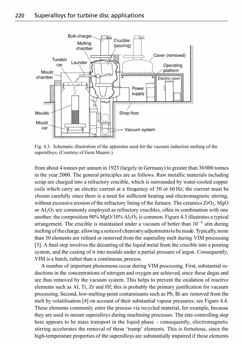
7/18/2019 The Superalloys Fundamentals and Applications
http://slidepdf.com/reader/full/the-superalloys-fundamentals-and-applications 238/389
220 Superalloys for turbine disc applications
Bulk charger
Meltingchamber
LaunderTundishcar
Mouldchamber
Moulds
Mouldcar Vacuum system
Shop floor
Operatingplatform
Powersupply
Electric room
Cover (removed)
Crucible(pouring)
Fig. 4.3. Schematic illustration of the apparatus used for the vacuum induction melting of the
superalloys. (Courtesy of Gern Maurer.)
from about 4 tonnes per annum in 1923 (largely in Germany) to greater than 30 000 tonnes
in the year 2000. The general principles are as follows. Raw metallic materials including
scrap are charged into a refractory crucible, which is surrounded by water-cooled copper coils which carry an electric current at a frequency of 50 or 60 Hz; the current must be
chosen carefully since there is a need for sufficient heating and electromagnetic stirring,
without excessive erosion of the refractory lining of the furnace. The ceramics ZrO2, MgO
or Al2O3 are commonly employed as refractory crucibles, often in combination with one
another; the composition 90% MgO/10% Al2O3 is common. Figure 4.3 illustrates a typical
arrangement. The crucible is maintained under a vacuum of better than 10−4 atm during
melting of thecharge, allowing a seriesof chemistry adjustments to be made. Typically, more
than 30 elements are refined or removed from the superalloy melt during VIM processing
[3]. A final step involves the decanting of the liquid metal from the crucible into a pouring
system, and the casting of it into moulds under a partial pressure of argon. Consequently,
VIM is a batch, rather than a continuous, process.
A number of important phenomena occur during VIM processing. First, substantial re-
ductions in the concentrations of nitrogen and oxygen are achieved, since these degas and
are thus removed by the vacuum system. This helps to prevent the oxidation of reactive
elements such as Al, Ti, Zr and Hf; this is probably the primary justification for vacuum
processing. Second, low-melting-point contaminants such as Pb, Bi are removed from the
melt by volatilisation [4] on account of their substantial vapour pressures; see Figure 4.4.These elements commonly enter the process via recycled material, for example, because
they are used to mount superalloys during machining processes. The rate-controlling step
here appears to be mass transport in the liquid phase – consequently, electromagnetic
stirring accelerates the removal of these ‘tramp’ elements. This is fortuitous, since the
high-temperature properties of the superalloys are substantially impaired if these elements

7/18/2019 The Superalloys Fundamentals and Applications
http://slidepdf.com/reader/full/the-superalloys-fundamentals-and-applications 239/389
4.1 Processing of the turbine disc alloys 221
0.1
0.01
C o n c e n t r a t i o n ( w t % )
0.001Te
Pb Bi
SeCu
0 20 40 60
Time (min)
80 100 120 140
Fig. 4.4. Evaporation of elements from Ni–20 wt%Cr alloy in a vacuum induction melting
furnace [4].
0 10
40
80
120
R u p t u r e l i f e ( h )
160
200
20 30 40 50
Impurity content (ppm)
Pb
Se
Ag
Bi
60 70 80 90
Fig. 4.5. Effect of various trace elements on the stress-rupture life of IN718 at 650 ◦C and 690MPa.
Data taken from ref. [5].
are present (see Figure 4.5); for IN718 tested in creep at 650 ◦C and 690MPa, the rupturelife is decreased ten-fold and two-fold by the addition of only 10 ppm of Bi and 40 ppm
of Pb, respectively [5]. This explains why strict limits are placed on the levels of trace
elements which are permissible in premium-grade superalloys, and justifies the emphasis
placed on compositional analyses during processing for quality assurance purposes. Finally,
desulphurisation of the melt is achieved typically by adding lime (CaO) and fluxing agents.

7/18/2019 The Superalloys Fundamentals and Applications
http://slidepdf.com/reader/full/the-superalloys-fundamentals-and-applications 240/389
222 Superalloys for turbine disc applications
Removal of slag, which also comes about via deterioration of the crucible lining and the
oxidised surfaces of revert material, is achieved mainly by flotation in launders built into
the pouring system, but also using ceramic ZrO2-based filters; these prevent it from being
incorporated into the solidified ingot.
4.1.1 Processing by the cast-and-wrought route
In practice, the VIM-cast material is not suitable for immediate use in gas turbine engines.
First, the level of segregation is so extreme that thermal-mechanical working of the ingot
would prove impossible should this be attempted. Second, theVIMingot is not mechanically
sound, since it contains a solidification pipe, cracks and porosity, which would need to be
machined away causing unnecessary wastage. Finally, a population of refractory particles
of ceramic is present; this needs to be reduced to more reasonable levels to ensure adequatefatigue resistance; see Section 4.3. These are introduced by erosion of the refractory lining
and by reactions such as
2Al+ 3MgO → Al2O3 + 3Mg (4.1)
where the reactants Al and MgO arise from the melt and lining, respectively. For these
reasons, superalloy stock processed by conventional cast-and-wrought processing is sub-
jected to further secondary melting processes such as vacuum arc remelting (VAR) and
possibly also electro-slag remelting (ESR). These reduce ingot pipe and improve the yield
and forgeability of the large ingots which are used for disc applications. For componentswhich demand the highest possible levels of cleanliness, triple-melted product is available:
this will have undergone VIM followed by ESR and finally VAR. Where triple melting is
employed, VAR will follow ESR because the different heat transfer characteristics allow the
production of a larger diameter ingot without causing melt-related defects such as freckles.
A Vacuum arc remelting
This involves the melting under vacuum of a consumable electrode into a copper-cooled
crucible; see Figure 4.6. The electrode is a casting which will have been produced either by
the VIM process or else the ESR process, which is described below. During processing, the
energy necessary for melting is provided by a DC arc, which is struck between the electrode
(the cathode) and the molten pool at the top of the solidifying ingot (the anode). The current
used is typically∼10 000 A, and the applied voltage is in the range 20 to 50 V. The scale of
the process is impressive; finished VAR ingots are several metres in length and weigh up to
20 tonnes.
The heat andmass transfer processesoccurring duringmelting have a profound influence
on the quality of the resulting VAR ingot. During processing, a thin molten film is formed on the electrode, which flows under gravity to form hanging protuberances. Metal transfer
occurs as droplets form and momentarily short circuit the arc as they fall from the molten
film. To maintain a constant arc gap, a ram arrangement is used to drive the electrode
into the VAR crucible as melting proceeds. Considerable emphasis is placed on control
strategies and process monitoring. For example, dynamic load cell weighing systems have

7/18/2019 The Superalloys Fundamentals and Applications
http://slidepdf.com/reader/full/the-superalloys-fundamentals-and-applications 241/389
4.1 Processing of the turbine disc alloys 223
Fig. 4.6. (a) Industrial-scale vacuum arc remelting (VAR) furnace (courtesy of Jai Narayan,
Consarc Corporation), (b) Schematic illustration of the VAR furnace. (c) Close-up of the details in
the vicinity of the molten pool.

7/18/2019 The Superalloys Fundamentals and Applications
http://slidepdf.com/reader/full/the-superalloys-fundamentals-and-applications 242/389
224 Superalloys for turbine disc applications
Table 4.1. Chemical analysis of the bulk and the defect area in wt%
Element Alloy White spot
Al 0.49 0.41Si 0.20 0.19Ti 0.81 0.62Cr 17.50 17.71Fe 17.75 19.21
Ni 54.97 55.70 Nb 5.10 2.96Mo 3.18 3.20T solidus 1242 ◦C 1309 ◦CT liquidus 1348 ◦C 1373 ◦C
Courtesy of Laurence Jackman
been developed to enable computerised control of the melt rate, which is typically in the
range 2–6 kg/min. As the electrode is melted, a liquid pool is produced which resides on the
already solidified material; the size and shape of the molten zone remains approximately
constant during processing, apart from brief transients associated with start-up andfinishing,
i.e. a steady-state is achieved. For a given electrode diameter, the depth of the pool increases
with the power input, the product of the current and the applied voltage; modelling work
[6] indicates that the efficiency of this process is in the range 50–75%, and that the current
enters the ingot at the meniscusand at the stool at the bottomof the coppercrucible onwhichthe solidified material sits. The molten pool is subjected to complex flow patterns, which are
due to a combination of the buoyancy forces, electromagnetic stirring and the Marangoni
effect arising from the temperature dependence of the surface tension. The velocity of the
molten material on the surface can reach 0.01 m/s; the flow pattern is radial, consistent with
the symmetry of the situation, and outward from the centre of the pool; see Figure 4.7.
The resulting ingot has a structure and chemistry far superior to the electrode being
melted. It will have reduced amounts of tramp elements, such as lead and bismuth, which
have substantial vapour pressures and are therefore volatilised. Degassing of oxygen and
nitrogen also occurs through the vacuum system, although it is difficult to remove them
completely when nitride-formingelements such as titaniumandniobium arepresent.Oxides
are removed by flotation and thermal dissociation; the former is generally more effective,
with surface tension and Marangoni forces playing a part in agglomerating the oxide debris.
On account of the enhanced cleanliness produced, VAR remains the most important and
widely used of the remelting practices for the superalloys.
Case study. Melt-related ‘white spot’ defects
Defects known as white spots are solute-lean regions which lack the hardening phases γ
and γ and the associated hardening elements such as Al, Ti and Nb [7,8]. The terminology
comes from the metallographical etching techniques which provide preferential attack,
leaving the solute-lean regions bright or white; see Figure 4.8 and Table 4.1. Experiments
have shown that mechanical properties, such as the yield stress and ultimate tensile strength

7/18/2019 The Superalloys Fundamentals and Applications
http://slidepdf.com/reader/full/the-superalloys-fundamentals-and-applications 243/389
4.1 Processing of the turbine disc alloys 225
Fig. 4.7. Results from the modelling of the VAR processing of a 0.5m diameter ingot of IN718
superalloy: (a) comparison between predicted and measured pool profile; (b) computed temperature
distribution in the ingot and the flow in the molten pool [6].
(UTS), are reduced when white spots are present, and this is obviously a cause for concern.
The VAR process is very much more prone to white spot than the ESR process, described
below. It should be noted that there is no known method for assuring the complete absence
of white spot from superalloy ingots for which VAR is the final remelting process. However,careful attention to process control for both VIM electrode production and VAR processing
reduces the probability of its occurrence.
Various mechanisms have been proposed for the formation of white spot, and it seems
probable that each occurs to some degree. However, a common feature is the falling of
material into the molten pool, such that its differing chemistry allows it to be incorporated

7/18/2019 The Superalloys Fundamentals and Applications
http://slidepdf.com/reader/full/the-superalloys-fundamentals-and-applications 244/389
226 Superalloys for turbine disc applications
Fig. 4.8. White-spot defect in the IN718 superalloy: (a) its appearance on a cross-section of a
macroetched billet; (b) optical micrograph. (Courtesy of Laurence Jackman.)
into the solidifying structure without it becoming remelted. This eventuality is more likely
for (i) solute-lean material with a melting temperature that is significantly larger than for
the bulk composition, (ii) larger particles which do not dissolve as readily as smaller ones
and (iii) larger local solidification times. Hence the frequency of white-spot occurrence is
dependent upon the resistance of the process to instabilities in the process.
Where does this material originate from? Studies have shown that one source is the
crown and shelf region, which occurs in the VAR process at the pool/crucible interface.
During processing, small changes in current distribution cause the centre of the pool to
shift, such that the remelting of some fraction of the crown is promoted; this is then under-cut and material is free to drop into the molten pool. A second possibility is fragmented
dendritic material from the electrode itself: obviously the interdendritic regions will melt
preferentially because of their lower melting point; this emphasises the importance of the
mechanical integrity of the electrode. Modelling studies [9] indicate that particles falling
from the electrode are likely to melt completely before entrapment in the mushy zone,

7/18/2019 The Superalloys Fundamentals and Applications
http://slidepdf.com/reader/full/the-superalloys-fundamentals-and-applications 245/389
4.1 Processing of the turbine disc alloys 227
Fig. 4.9. (a) Schematic illustration of the apparatus used for the electro-slag remelting of
superalloys. (b) Close-up of the details in the vicinity of the molten pool.
provided that their diameter is greater than 6 mm; crown fall-in was considered to be a more
likely source of white spot, since the maximum safe diameter of material falling into the
pool was found to be in the range 2 to 3 mm.
B Electro-slag remelting
Electro-slag remelting (ESR) is used widely as a secondary melting process for the produc-
tion of the material for turbine discs; see Figure 4.9. It has similarities to the VAR process
in that a consumable electrode is remelted, but here a molten slag pool sits between the
electrode and the solidifying ingot – hence processing can be carried out in air. A major
significant advantage over VAR processing then arises: molten droplets from the electrode
pass through the slag, allowing them to react with it such that impurities such as oxides
and sulphur are removed. However, unlike the VAR process, an alternating current (AC)
is applied; the electrode immersion plus the slag cap must be regarded as the major resis-
tance in the circuit; consequently, the majority of the heat generation occurs in this region.
Changing the weight of slag in the system alters the resistance of the circuit and thus the
current and voltage required to maintain a given power input/melt rate.A number of processing controls are used which aid in the production of ingots of high
quality andconsistency. First, a constant immersionof theelectrodein theslag is maintained,
via control of the electrode voltage. Second, one monitors the rate at which the electrode
melts by measuring the loss of electrode weight during processing, and adjusts the current
accordingly. During solidification, slag may be added or removed as processing proceeds

7/18/2019 The Superalloys Fundamentals and Applications
http://slidepdf.com/reader/full/the-superalloys-fundamentals-and-applications 246/389
228 Superalloys for turbine disc applications
Fig. 4.10. Sections of ESR-melted superalloy billet, showing extensive evidence of the freckle
defect. (Courtesy of Laurence Blackman.)
to maintain a uniform head over the pool. The choice of slag is critical, since it determines
the reactivity with the molten droplets via different melting temperatures and viscosities.The slags are normally based upon fluorite CaF2 with additions of CaO, MgO and Al2O3.
Impurities of SiO2 can cause problems, since Ti reduces it to metallic Si which will be
incorporated into the ingot. This is managed by recycling the slag, which then approaches
an equilibrium with Ti and Si pickup, thus minimising elemental exchange. In practice,
minor changes in alloy chemistry are caused in this way; ESR is much more prone to this
effect than VAR.
One disadvantage of the molten slag is that it acts as a heat reservoir at the top of
the ingot/pool boundary and this makes the fusion profile obtained from the ESR process
different from that obtained from VAR; generally with steeper sides, larger mushy zones
and decreased cooling rates for comparable power input. These factors promote levels
of chemical heterogeneity that are greater in ESR than in VAR processing; hence where
triple melting is employed, ESR will always precede VAR.Additionally, the maximum ingot
diameter which can be melted by ESR is dependent upon alloy composition. This is because
large diameters promote a greater mushy zone and enhanced local solidification times, due
to the increased distances. For this reason the processing of higher-strength alloys such as
U720Li is limited to diameters of about 500mm or 20 inches. Attempts have been made
[10] to use ESR processing for the production of very large 890 mm (35 inch) IN718 ingotsof weight approaching 14 tonnes, each of which is sufficient for just two turbine discs for a
large land-based turbine. It was reported that no conditions could be found which yielded
ingots that were free of extensive freckling; the heavy freckle channels were found to be
rich in elements such as Nb, Mo and Ti, which are known to partition to the liquid phase.
Subsequent VAR processing was used to produce sound triple-melted (VAR + ESR +

7/18/2019 The Superalloys Fundamentals and Applications
http://slidepdf.com/reader/full/the-superalloys-fundamentals-and-applications 247/389
4.1 Processing of the turbine disc alloys 229
VAR) 760 mm (30 inch) product for this application. Figure 4.10 illustrates the formation
of freckle defects in ESR-processed ingots of IN718; their occurrence seems to be most
likely at the mid-radius position, where the permeability of the mushy zone is greater than
at the centre of the ingot and is deep enough to support the interdendritic fluid flow required
for their formation [11].
C Ingot-to-billet conversion: the cogging process
The ingots produced by the remelting processes are unsuitable for mechanical applications:
they must undergo thermal-mechanical working in order to break down the as-cast structure
and to reduce the grain size to acceptable levels, i.e. from a few tens of millimetres to a few
tens of microns. This is known as ingot conversion and it is usually achieved by a process
known as cogging , during which the diameter of the cylindrical ingot is reduced in size by a factor of approximately 2, so that its length increases four-fold, see Figure 4.11. The
conversion is achieved in a series of stages, or heats. The ingot is placed in a furnace and
allowed to reach an appropriate temperature for forging. Upon removal, it is manipulated
between two horizontal dies which are driven hydraulically. These squeeze (or bite) the
material, causing it to deform both in and out of the plane of the dies. Typically the ingot is
deformed 20 to 30 times at various points along its length, with the pattern repeated with
the ingot rotated through 90◦, 45◦ and one final turn of 90◦. At the end of this procedure,
the ingot is returned to the furnace now with a characteristic octagonal cross-section. The
deformation applied to the ingot causessubstantial recrystallisation to a finer grain structure.After reheating the whole process is repeated.
To reducea 60cmdiameter ingot downto the required30cm orsoasmany assevenheats
may be required. In the later heats a temperature below the relevant solvus (for example,
1040 ◦C for the γ in Waspaloy, 1010 ◦C for the δ in IN718) is employed to ensure that grain
growth following deformation is inhibited. Usually, a final rounding operation is performed
prior to slicing the billet for the subsequent forging operations. Typically the starting grain
size is around ASTM000 (1 mm+), but, by the start of the third heat, the grain size has been
reduced toaroundASTM0 (0.35 mm).At the end of the process the grain size isASTM5 or6
(40–60 μ m). Other ingot-to-billet conversion processes are possible, for example, gyratory
forging machine (GFM) or radial forging, the principal difference being the strain profile
imparted during processing.
D Open- and closed-die forging
Having achieved a fine-grained uniform structure through the conversion process, the ob-
jective of the forgemaster is to turn the cylinder of metal into a shape close to that of the
turbine disc. The principal concern at this stage is not to promote excessive grain growth.Again the production of the disc is usually a three-stage process, typically comprising
(i) upsetting by open-die forging, to produce an axisymmetric ingot of reduced thickness
and greater cross-sectional area, (ii) blocking by closed-die forging, to place thicker and
thinner sections in the appropriate place, and (iii) finishing, again by closed-die forging, to
produce the desired disc shape. In these three operations the temperature is typically kept

7/18/2019 The Superalloys Fundamentals and Applications
http://slidepdf.com/reader/full/the-superalloys-fundamentals-and-applications 248/389
230 Superalloys for turbine disc applications
(a)
(b)
Fig. 4.11. (a) Cogging operation for the thermal-mechanical working of a superalloy billet.
(b) Cross-sections of the worked billet after various stages of working – with the unworked billet
at left. (Courtesy of Mark Roberts.)
very close to the appropriate solvus of the alloy being forged, thereby ensuring that any
recrystallisation that does occur results in a finer grain structure than that achieved in the
conversion stage. At the end of processing the forged discs are either quenched into a bath
of oil or water, or else left to cool on the shop floor.A heat treatment is then applied to encourage the appropriate strengthening phases (for
example, γ ) to precipitate in sufficient quantities to give the necessary high-temperature
properties. A quenching operation, typically into oil, is employed following the heat treat-
ment to ‘freeze in’ the precipitation structure. Next, the discs are machined to a pre-specified
geometry which is known as the ‘condition of supply’; this is usually rectilinear to allow

7/18/2019 The Superalloys Fundamentals and Applications
http://slidepdf.com/reader/full/the-superalloys-fundamentals-and-applications 249/389
4.1 Processing of the turbine disc alloys 231
non-destructiveevaluation (NDE) of the forgingviaultrasonic testing.Finally, the rectilinear
forging is machined to the final shape required for the turbine disc. These steps are obviously
such that the mass of material in the final machined disc is only a small fraction of that in the
turbine disc forging from which it is made. Consider, for example, an HP turbine disc for
Rolls-Royce Corporation’s AE3007 engine which powers the Cessna Citation X business
jet. The final disc weighs about 8kg, but it is machined from a disc of mass 45 kg.
Case study. Process modelling of forging operations
Although superalloys have been used for the turbine discs in jet engines for about 50 years,
the processing is not without some challenges. The manufacturing stream is quite lengthy,
involving a number of material suppliers, melters and forgemasters; at each stage there is
a risk that defects will be introduced. Whilst these are usually detected by quality control procedures such as ultrasonic inspection, they nonetheless contribute to material wastage
and hence to extra cost. Possible defects include (i) inadequate control of grain size and
(ii) forging defects such as laps or inadequate filling of the dies.
Process modelling is one way of responding to this situation. Here, one builds mathe-
matical models of the phenomena occurring during the manufacturing route. This should
include continuum phenomena such as heat flow as well as the stresses and strains which are
developed during deformation. However, it is becoming increasingly possible to simulate
microstructure evolution such as recrystallisation, grain growth and texture. The emphasis
is always on including as much as possible of the underlying theory, without making thesimulations unwieldy, intractable or lengthy. It is important to have accurate thermophysical
properties of the material, and a good estimate of the stress–strain behaviour at elevated
temperatures.
There are many advantages of building a process model for the forging processes, as
follows. A model, if sufficiently accurate, will have considerable predictive capability;
see Figure 4.12. Models can be used to study the effect of changing process variables
(such as die geometry, bite size, quenching rate) without resorting to experimental trials.
They can therefore be used to optimise the processing in order to eliminate or reduce
manufacturing waste. Furthermore, they generally help to reducethenumberofdesign/make
iterations required during component prototyping – this leads to savings in both time and
money.
4.1.2 Processing by the powder route
The need for powder metallurgy (P/M) [12] for the production of superalloy turbine discs
became apparent in the 1970s due to the development of alloys such as Rene 95, Astroloy
and MERL 76 (with strength levels higher than earlier alloys such IN718 and Waspaloy),which were found to be unamenable to processing into the cast-and-wrought form. Initially,
the use of P/M product was limited to gas turbines for military purposes, for example, the
Pratt & Whitney F100 engine for the F-15 Eagle fighter, which entered service in 1974 [13],
but commercial applications such as General Electric’s CF6-80 engine for the Boeing 747-
400 and the GE90 for the Boeing 777 have emerged as experience has been accumulated.

7/18/2019 The Superalloys Fundamentals and Applications
http://slidepdf.com/reader/full/the-superalloys-fundamentals-and-applications 250/389
232 Superalloys for turbine disc applications
Fig. 4.12. (a) Photomicrograph of a closed-die forging in the IN718 superalloy; (b) computer
simulation of the recrystallised regions in the forging, with the dead zones at top and bottom.
(Courtesy of Rob Guest.)
Advantages of powder-processing include improved property uniformity due to the elim-
ination of macrosegregation and the development of a fine grain size. The disadvantages
are the extra cost associated with the production of the powder (this is offset somewhat
by the number of processing steps being fewer) and, arguably, the extra complexity of the
probabilistic lifing method required; see Section 4.3.
The first step in the production of P/M product is inert gas atomisation from master
melts produced by VIM processing; clearly, the cleanliness of these is important since
any contamination will be inherited by the powder. A typical arrangement is shown in
Figure 4.13. Molten metal is poured into a tundish, which contains a carefully designed
ceramic nozzle surrounded by one or more inert gas jets; usually argon is preferred. A
continuous stream of gas at high pressure is delivered to the stream of molten metal arriving
at thenozzle, theactionof whichcauses itsdisintegration into sphericalparticles of diameter
30 to300 μ m. The atomisation chamber is designed to be long enough to allow solidification
of the particles before they reach the outlet of the chamber. Cooling rates are typically in
excess of 100 ◦C/s, being greater for finer particles. Figure 4.14 shows a SEM micrographof powder produced in this way. A number of variants of the process have been developed
with varying degrees of success, for example, soluble-gas atomisation in which atomisation
is induced by inserting a ceramic tube into the melt, the open end of which is connected
to a vacuum chamber; the dissolution of a soluble gas (usually hydrogen) over the molten
metal aids the atomisation process.

7/18/2019 The Superalloys Fundamentals and Applications
http://slidepdf.com/reader/full/the-superalloys-fundamentals-and-applications 251/389
4.1 Processing of the turbine disc alloys 233
Fig. 4.13. Typical arrangement for the Ar atomisation used for the production of superalloys by
powder metallurgy. (Courtesy of Tim Howson.)
Consolidation of the powder involves processing by extrusion. The fundamental chal-
lenge is to obtain good metallurgical bonding across the prior particle boundaries; to ensure
bonding across oxide films which are inevitably present, the particles must be brought into
contact at temperature and subjected to pressure and mechanical deformation. The powder
is first packed into a carefully cleaned steel container. This is evacuated to encourage out-
gassing, sealed and then compacted either by hot isostatic pressing (HIP) or occasionally
using closed-die forging. A very high-tonnage press with specialised tooling is then used toextrude the material to the high reduction ratios necessary for fine-grained billet; this step
has been shown to disperse any non-metallic inclusions still present, thus improving the
defect tolerance of the material. Some attempts have been made to eliminate the extrusion
step, replacing it, for example, with a sub-solidus, hot isostatic pressing (SSHIP) process
[14]; this is followed by conventional ingot-to-billet conversion of the type employed for

7/18/2019 The Superalloys Fundamentals and Applications
http://slidepdf.com/reader/full/the-superalloys-fundamentals-and-applications 252/389
234 Superalloys for turbine disc applications
Fig. 4.14. Scanning electron micrograph of gas atomised IN718 powder.
superalloys produced by ingot metallurgy, involving thermal-mechanical working by cog-
ging and closed-die forging.
Isothermal forging – in which the billet is deformed at the same temperature as thedies, both being held in a well-instrumented furnace – is the preferred route by which
P/M superalloy product is shaped after powder consolidation. Superplastic behaviour is
observed on account of the small grain size and because the deformation rates are relatively
low (in the range 0.002 to 0.03/s) and stresses are high (50 to 100MPa at 1200 ◦C). Several
advantages then arise. Recrystallisation and grain growth can be controlled; for example,
the considerable variations in microstructure arising from cold-die forging, due to excessive
grain growth and die-chill, are avoided. Second, significant savings in material can be made
since forgings can be produced of a geometry very close to the ‘sonic shape’ required by
ultrasonic testing. Figure 4.15 illustrates possible processing sequences for the compressor
discs of the GE F-101 engine, which was one of the first applications of the Rene 95 P/M
superalloy [13].
When P/M processing was first applied to the production of turbine discs, the material
was susceptible to the presence of defects – this was problematical in view of the need for fa-
tigue resistance. Althoughthesituationhasimproved very markedly, it is imperative to guard
against the possibility of their presence. Consequently, the highest standards of handling are
required, processing steps need to be strictly adhered to and quality assurance procedures
must be enforced. For example, residual voids, pores and prior particle boundaries (PPBs)will be present if the steps taken to consolidate the powder are inadequate. Contamination by
metallic inclusions remains a possibility, forexample,bycross-contamination with a foreign
alloy powder; this eventuality can be minimised by cleaning the chamber using washing
runs. Of greatest concern is the possible presence of ceramic inclusions in the material,
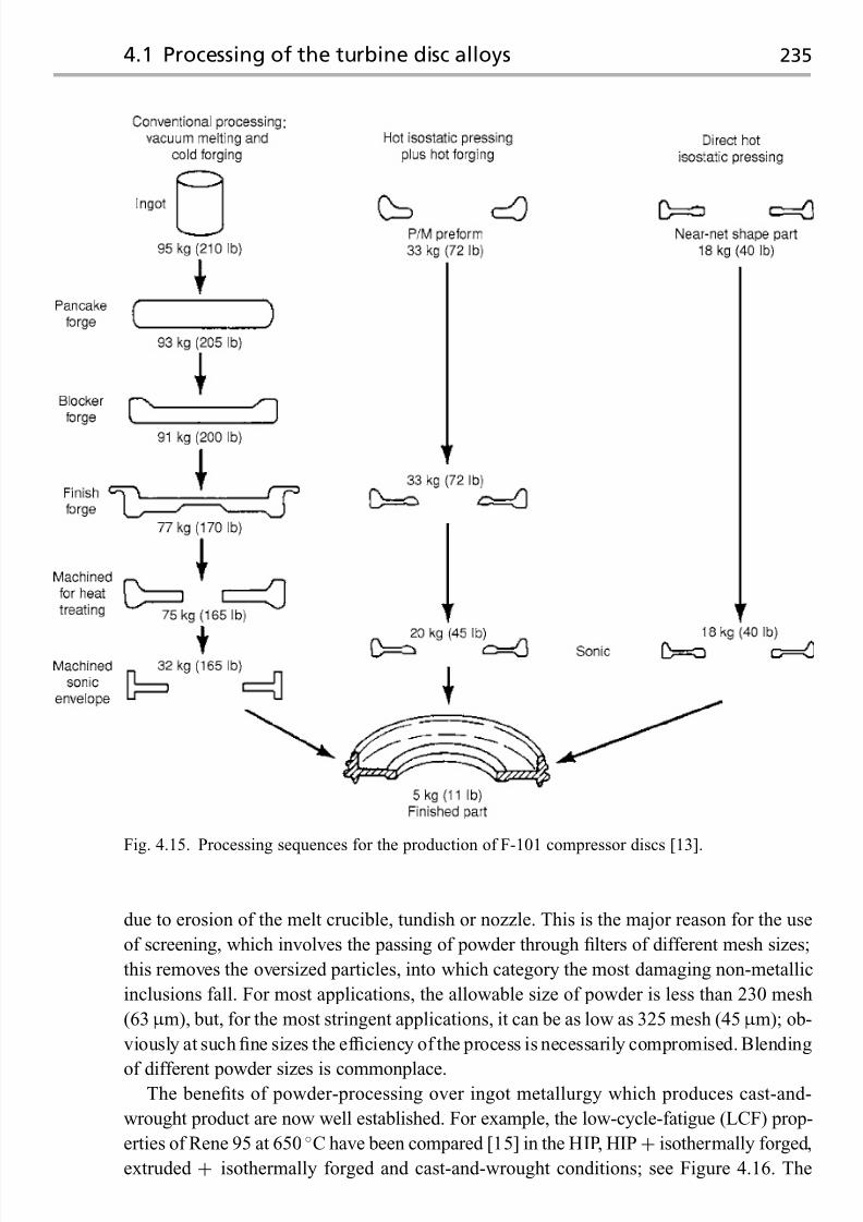
7/18/2019 The Superalloys Fundamentals and Applications
http://slidepdf.com/reader/full/the-superalloys-fundamentals-and-applications 253/389
4.1 Processing of the turbine disc alloys 235
Fig. 4.15. Processing sequences for the production of F-101 compressor discs [13].
due to erosion of the melt crucible, tundish or nozzle. This is the major reason for the use
of screening, which involves the passing of powder through filters of different mesh sizes;
this removes the oversized particles, into which category the most damaging non-metallic
inclusions fall. For most applications, the allowable size of powder is less than 230 mesh
(63μ m), but, for the most stringent applications, it can be as low as 325 mesh (45 μ m); ob-
viously at such fine sizes the efficiency of the process is necessarily compromised. Blending
of different powder sizes is commonplace.The benefits of powder-processing over ingot metallurgy which produces cast-and-
wrought product are now well established. For example, the low-cycle-fatigue (LCF) prop-
erties of Rene 95 at 650 ◦C have been compared [15] in the HIP, HIP+ isothermally forged,
extruded + isothermally forged and cast-and-wrought conditions; see Figure 4.16. The

7/18/2019 The Superalloys Fundamentals and Applications
http://slidepdf.com/reader/full/the-superalloys-fundamentals-and-applications 254/389
236 Superalloys for turbine disc applications
1.6
1.4
1.2
1.0
0.8 Δ ε t
( % )
0.6
0.4
101 102 103
N f (cycles)
104 105 106
EX+FHIPC&WSub-surface failureTest stopped
Fig. 4.16. Comparison of low-cycle-fatigue
data for the Rene 95 superalloy at 650 ◦C,
in the powder and cast-and-wrought
(C&W) forms [15]; EX
+F refers to extrusion
and isothermal forging, and HIP is hotisostatic pressing.
best properties were displayed by extruded-and-forged material and the worst by the con-
ventional cast-and-wrought processing, with the behaviour of the HIP material between
the two; the differences were most pronounced at low total strain ranges. It was noted
that, in all cases, the LCF lives were limited by the presence of ceramic inclusions –
it was recommended that much further effort be expended to reduce or eliminate these
defects.
4.2 Composition, microstructure and properties of turbine disc alloys
Ourconsiderationsindicate that theoperatingtemperatures for turbinediscs areconsiderably
lower than for turbine blading, but that the stresses experienced are much greater. Under
these circumstances, the properties required of a turbine disc alloy can be summarised as
follows: (i) high yield stress and tensile strength to prevent yield and fracture, (ii) ductility
and fracture toughness, to impart tolerance to defects, (iii) resistance to the initiation of
fatigue cracking and (iv) fatigue crack propagation rates that are as low as possible. Creep
resistance is also important, but traditionally it has been given less emphasis due to the
lower operating temperatures and because a stress relaxation capability around notches and
features of stress concentration is desirable.
What factors must be accounted for when designing a turbine disc alloy, or else when
choosing one from the list of those available? Table 4.2 provides the compositions of some
turbine disc alloys which are used in gas turbine engines [16]. Unsurprisingly, the chemical
composition is found to be of crucial importance; however, just as importantly, if the best properties are to be attained then the microstructure must be conditioned in an optimum
way. An added complexity, which does not apply to the case of the single-crystal superalloys
considered in the previous chapter, is the presence of grain boundaries – these must be
carefully engineered. Thus a strongappreciationof the relationship between alloy chemistry
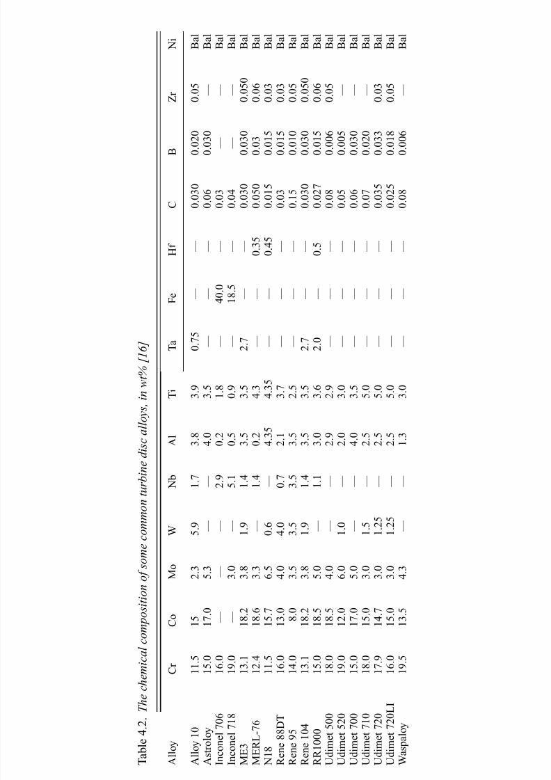
7/18/2019 The Superalloys Fundamentals and Applications
http://slidepdf.com/reader/full/the-superalloys-fundamentals-and-applications 255/389
T a b l e 4 . 2 . T h e c h e m i c a l c o m p o s i t i o n o f s o m e
c o m m o n t u r b i n e d i s c a l l o y s ,
i n w t % [ 1 6 ]
A l l o y
C r
C o
M o
W
N b
A l
T i
T a
F e
H f
C
B
Z r
N i
A l l o y 1 0
1 1 . 5
1 5
2 . 3
5 . 9
1 . 7
3 . 8
3 . 9
0 . 7 5
—
—
0 . 0 3 0
0 . 0 2 0
0 . 0 5
B a l
A s t r o l o y
1 5 . 0
1 7 . 0
5 . 3
—
—
4 . 0
3 . 5
—
—
—
0 . 0 6
0 . 0 3 0
—
B a l
I n c o n e l 7 0 6
1 6 . 0
—
—
—
2 . 9
0 . 2
1 . 8
—
4 0 . 0
—
0 . 0 3
—
—
B a l
I n c o n e l 7 1 8
1 9 . 0
—
3 . 0
—
5 . 1
0 . 5
0 . 9
—
1 8 . 5
—
0 . 0 4
—
—
B a l
M E 3
1 3 . 1
1 8 . 2
3 . 8
1 . 9
1 . 4
3 . 5
3 . 5
2 . 7
—
—
0 . 0 3 0
0 . 0 3 0
0 . 0 5 0
B a l
M E R L - 7 6
1 2 . 4
1 8 . 6
3 . 3
—
1 . 4
0 . 2
4 . 3
—
—
0 . 3 5
0 . 0 5 0
0 . 0 3
0 . 0 6
B a l
N 1 8
1 1 . 5
1 5 . 7
6 . 5
0 . 6
—
4 . 3 5
4 . 3 5
—
—
0 . 4 5
0 . 0 1 5
0 . 0 1 5
0 . 0 3
B a l
R e n e 8 8 D T
1 6 . 0
1 3 . 0
4 . 0
4 . 0
0 . 7
2 . 1
3 . 7
—
—
—
0 . 0 3
0 . 0 1 5
0 . 0 3
B a l
R e n e 9 5
1 4 . 0
8 . 0
3 . 5
3 . 5
3 . 5
3 . 5
2 . 5
—
—
—
0 . 1 5
0 . 0 1 0
0 . 0 5
B a l
R e n e 1 0 4
1 3 . 1
1 8 . 2
3 . 8
1 . 9
1 . 4
3 . 5
3 . 5
2 . 7
—
—
0 . 0 3 0
0 . 0 3 0
0 . 0 5 0
B a l
R R 1 0 0 0
1 5 . 0
1 8 . 5
5 . 0
—
1 . 1
3 . 0
3 . 6
2 . 0
—
0 . 5
0 . 0 2 7
0 . 0 1 5
0 . 0 6
B a l
U d i m e t 5 0 0
1 8 . 0
1 8 . 5
4 . 0
—
—
2 . 9
2 . 9
—
—
—
0 . 0 8
0 . 0 0 6
0 . 0 5
B a l
U d i m e t 5 2 0
1 9 . 0
1 2 . 0
6 . 0
1 . 0
—
2 . 0
3 . 0
—
—
—
0 . 0 5
0 . 0 0 5
—
B a l
U d i m e t 7 0 0
1 5 . 0
1 7 . 0
5 . 0
—
—
4 . 0
3 . 5
—
—
—
0 . 0 6
0 . 0 3 0
—
B a l
U d i m e t 7 1 0
1 8 . 0
1 5 . 0
3 . 0
1 . 5
—
2 . 5
5 . 0
—
—
—
0 . 0 7
0 . 0 2 0
—
B a l
U d i m e t 7 2 0
1 7 . 9
1 4 . 7
3 . 0
1 . 2 5
—
2 . 5
5 . 0
—
—
—
0 . 0 3 5
0 . 0 3 3
0 . 0 3
B a l
U d i m e t 7 2 0 L I
1 6 . 0
1 5 . 0
3 . 0
1 . 2 5
—
2 . 5
5 . 0
—
—
—
0 . 0 2 5
0 . 0 1 8
0 . 0 5
B a l
W a s p a l o y
1 9 . 5
1 3 . 5
4 . 3
—
—
1 . 3
3 . 0
—
—
—
0 . 0 8
0 . 0 0 6
—
B a l

7/18/2019 The Superalloys Fundamentals and Applications
http://slidepdf.com/reader/full/the-superalloys-fundamentals-and-applications 256/389
238 Superalloys for turbine disc applications
00
100
400 Y i e l d s t r e s s a t 6 5 0 ° C ( M P a )
800
600
1000
1200
1400
0.1 0.2 0.3 0.4
Fraction of strengthening phases (γ ′ + γ ′′)
0.5 0.6 0.7 0.8
Hastelloy XHastelloy C-22
Nimonic 75
Inconel 706
Inconel 718
Inconel 597Inconel X750
Inconel 625
Nimonic 263 Nimonic PE.16
Nimonic 80A
Nimonic PE.11
Nimonic PK.33 Nimonic 105
Nimonic 115
Nimonic 942
Ni-90
Inconel 587
M-252
Waspaloy
Rene 41
Udimet 520
Pyromet 860
Udimet 530
Udimet 500
Udimet 720
Rene 95
Udimet 710Udimet 700
N18
MERL76RR1000Astroloy
Fig. 4.17. Variation of the yield stress at 650 ◦C with the total fraction of the γ and γ
strengthening phases, for a number of common turbine disc alloys.
and microstructure is required if an optimum combination of properties is to be achieved.
The experience gained so far indicates that the following three guidelines should be
adhered to.
4.2.1 Guideline 1
To impart strength and fatigue resistance, the fraction of theγ phase should beoptimised by appropriate choice of theγ -forming elements (Al, Ti and Ta) – placing it
in the range 40% to 55% – and heat treatments chosen to promote a uniform
distribution of γ particles.
The yield stresses of the turbine disc alloys correlate very strongly with the proportions of
the strengthening phases γ and γ , and thus a first overriding concern when designing a
turbine disc alloy is the choice of the concentration of elements which promote these phases,
such that the desired strength levels are achieved. One can see this by using thermodynamicsoftware such as Thermo-Calc to estimate the fractions of γ and γ present in the alloys
given in Table 4.1, and comparing the predictions with mechanical property data. The
results, see Figure 4.17, confirm that the yield stress at 650 ◦C correlates very strongly with
the sum of the fractions of the strengthening phases; the yield stress at ambient temperature
behaves in the same way. The creep performance, for example the stress for 1000 h life at

7/18/2019 The Superalloys Fundamentals and Applications
http://slidepdf.com/reader/full/the-superalloys-fundamentals-and-applications 257/389
4.2 Composition, microstructure and properties 239
00
100
200
300
400
1 0 0 0 h r u p t u r e s t r e n g t h a t 7 0 0 ° C ( M
P a )
500
600
700
800
900
0.1 0.2 0.3 0.4
Fraction of strengthening phases (γ ′ + γ ′′)
0.5 0.6 0.7 0.8
Hastelloy X
Inconel 625
Nimonic 80A
Inconel 718M-252
Waspaloy
Rene 41
Udimet 520
Udimet 500
Udimet 710
Udimet 700
N18RR1000
Astroloy
Fig. 4.18. Variation of the 1000 h creep rupture strength at 700 ◦C with the total fraction of the γ
and γ strengthening phases, for a number of common turbine disc alloys.
1.4Yield strength
UTS1.2
‘ S i g n
i f i c a n c e ’ ( a r b i t r a r y
u n i t s )
1.0
0.8
0.6
0.4
0.2
0.0 Ni Cr Co Mo W Ta Nb Al Ti Fe Mn Si C B Zr Temperature
Fig. 4.19. The relative ‘significance’ of the elemental concentrations and temperature for a neural
network analysis of the yield and ultimate tensile strength (UTS) of turbine disc superalloys [17].
700 ◦C, shows a similar correlation; see Figure 4.18. These findings have been confirmed
by a neural network analysis [17] on a dataset containing information on the compositions
and strength levels of over 200 polycrystalline superalloys; this has confirmed that theconcentrations of Al, Ti and Nb are the most influential in improving the yield properties;
see Figure 4.19. Interestingly, when the neural network was interrogated after being trained,
it predicted that higher Ti/Al ratios are important in conferring strength (see Figure 4.20);
this is consistent with the hardening theories of Chapter 2, which emphasise the importance
of the APB energy, which increases as the Ti/Al ratio is raised [18]. Cobalt was found to

7/18/2019 The Superalloys Fundamentals and Applications
http://slidepdf.com/reader/full/the-superalloys-fundamentals-and-applications 258/389
240 Superalloys for turbine disc applications
1600
1400
1200
S t r e n g t h ( M P
a )
Titanium/aluminium ratio
1000
800
600
0.0 0.2 0.4 0.6 0.8 1.0 1.2
Tensile
Yield
Fig. 4.20. Predicted sensitivity of the room
temperature yield and tensile (UTS) strength
to variations in the Ti/Al ratio, using a neural
network analysis [17].
have negligible effect on the yield properties, but increasing proportions of molybdenum
were predicted to be beneficial – using Astroloy as a baseline, an increase in concentration
from zero to 20 wt%Mo was predicted to improve the yield stress by about 500 MPa. This
information about the beneficial effect of Mo was used to help optimise the composition of
the RR1000 superalloy; see Table 4.1. The importance of a high Ti/Al ratio in conferring
strength can be further demonstrated by considering the data; if one plots the yield stress
against the root of the sum of the strengthening phases, a reasonably straight line is found,
consistent with the hardening theories of Chapter 2 – one can then determine the extent towhich any one alloy lies above or below this ‘mean’, or expected, behaviour. The results are
given in Figure 4.21. One can see that the alloys with high Ti/Al ratio are the ones which
possess the highest strength, consistent with the neural network analysis of [17].
In practice, the yield stress of a turbine disc alloy has been found to depend critically
on the heat treatment applied to it – particularly the solutioning treatment, which is carried
out in the vicinity of the γ solvus. This is because, as indicated by the theoretical analysis
given in Chapter 2, the size of the γ particles is as crucial as their volume fraction in
determining the resistance to dislocation motion. For most turbine disc alloys, the γ solvus
lies between 1050 ◦C and 1200 ◦C, the exact value being dependent upon the chemical
composition. If the solutioning heat-treatment temperature is sub-solvus, the undissolved,
or primary, γ precipitates have a grain-pinning effect which restricts γ -grain growth;
see Figure 4.22. Super-solvus heat treatment eliminates the primary γ and the γ grains
are correspondingly coarser. It follows that the γ phase distribution is, in practice, rather
complex; see Figure 4.23, which is a schematic illustration of the microstructure of a turbine
discalloy [19]. Inaddition to the primaryγ , intragranularsecondaryandtertiaryγ particles
are present within the γ grains, typically at particle diameters of ∼100nm and ∼50nm,
respectively. This bimodal distribution occurs because of the interplay between the kineticsof γ particle nucleation,growthand coarsening,whichoccursduring isothermalsolutioning
and ageing heat treatments; the cooling rate is also important since the equilibrium fraction
of γ is rarely attained during these, so that further γ nucleation and growth occurs during
cooling. During the ageing heat treatment, which is typically carried out at around 700 ◦Cfor several hours, an age-hardening response is observed, as in many precipitation-hardened

7/18/2019 The Superalloys Fundamentals and Applications
http://slidepdf.com/reader/full/the-superalloys-fundamentals-and-applications 259/389
4.2 Composition, microstructure and properties 241
Fig. 4.21. Variation of the Ti/Al ratio in a number of polycrystalline superalloys, ranked in order of
strength consistent with a deviation away from a perfect correlation of yield stress and the square
root of the fraction of strengthening phases.
systems. The data in Figure 4.24 for the yield stress and UTS of the Udimet 720Li superalloy
illustrate this; in this case, the length of the heat treatment is optimal at about 30 h [19].
When the γ particle distributions giving rise to this behaviour are examined, one finds that
the size of the secondary γ particles is unaltered by the heat treatment; see Figure 4.25.
On the other hand, the tertiary γ coarsens considerably, and this proves unambiguously
that it controls the strength level achieved. Clearly, the heat treatment must be chosen
carefully if optimum properties are to be attained. On the basis of these observations,
one can argue that, for absolute static strength, higher solutioning temperatures are to be
preferred, since the proportion of primary γ is then reduced, so that a greater proportion
of the available γ is then placed in the range 50 nm to 100 nm where it has the greatest
effect.
The situation, however, is complicated because the fatigue properties must also be con-sidered. The distribution of theγ precipitates has been found to have a significant influence
on the dwell-time fatigue crack propagation (FCP) rate; for example, an improvement in
FCP rate in the Paris regime of about an order of magnitude has been reported in ref. [20]
when heat treatment was super-solvus rather than sub-solvus, this microstructural effect
being more potent than minor changes in chemistry involving Nb/Ta ratio and Co content

7/18/2019 The Superalloys Fundamentals and Applications
http://slidepdf.com/reader/full/the-superalloys-fundamentals-and-applications 260/389
242 Superalloys for turbine disc applications
Fig. 4.22. Optical micrographs of RR1000 superalloy: (a) sub-solvus heat-treated for 4 h at
1130 ◦C; (b) super-solvus heat-treated for 4 h at 1170 ◦C. The solvus temperature in this alloy is
about 1150◦C. Note the grain-pinning effect, which occurs when the heat-treatment temperature is
sub-solvus. (Courtesy of Rob Mitchell.)

7/18/2019 The Superalloys Fundamentals and Applications
http://slidepdf.com/reader/full/the-superalloys-fundamentals-and-applications 261/389
4.2 Composition, microstructure and properties 243
Fig. 4.23. Schematic illustration of the distribution of the γ phase in a turbine disc alloy [19].
1625(a)
(b)
(c)
(d)
1525
1425
1325
1225
1125
1025
92516 20 24 28 32 36
Ageing time at 700 °C (h)
S t r e s s ( M P a )
40 44 48 52 56 60
Fig. 4.24. Hardening response of the Udimet 720Li superalloy due to heat treatment at 700 ◦C [19].
(a) Room temperature, UTS; (b) room temperature, 0.2% proof stress; (c) UTS at 600 ◦C; (d) 0.2%
proof stress at 600 ◦C.

7/18/2019 The Superalloys Fundamentals and Applications
http://slidepdf.com/reader/full/the-superalloys-fundamentals-and-applications 262/389
244 Superalloys for turbine disc applications
25
20
15
10
5
0
0 30 60 90γ ′ size (nm)
F r e q u e n c y
16 h
24 h
42 h
120 150
Fig. 4.25. Characterisation of the bimodal distribution of γ in the Udimet 720Li superalloy and its
response to ageing at 700 ◦C [19].
Fig. 4.26. Dwell fatigue crack propagation
data for seven P/M superalloys at 704 ◦C and
a 90 s hold, with R = 0.1 [20]. The base
composition was Ni–11Cr–2.6Mo–3.8
Ti–3.9Al–5.7W, with 0.04, 0.03 and 0.1 of the
trace elements C, B and Zr; Nb, Ta and Co
were varied between 0 and 1, 1 and 2 and 15and 19, respectively. All figures in wt%.
Super-solvus processing clearly has a greater
influence than modifications in the
composition of the alloy.
(see Figure 4.26). When super-solvus processing was employed, the cooling rate was also
found to be important at constantγ -grain size; the FCP rate increased by about a factor of 4
at a K max of 25MPa m1/2 when air cooling rather than furnace cooling was employed – be-
cause the γ particle size decreased from 250nm to 170nm; see Figure 4.27. Combinationsof the original super-solvus heat treatment followed by subsequent sub-solvus heat treat-
ment were shown to be very detrimental, with a further increase in FCP rate of at least 3 –
this can be attributed to the dissolution of the larger γ particles and the reprecipitation
of smaller ones upon cooling. From these observations it seems that the γ particle size

7/18/2019 The Superalloys Fundamentals and Applications
http://slidepdf.com/reader/full/the-superalloys-fundamentals-and-applications 263/389
4.2 Composition, microstructure and properties 245
Fig. 4.27. Dwell fatigue crack propagation data at 704 ◦C (90s hold and R = 0.1) for an
experimental P/M superalloy, heat-treated to give different γ sizes [20]: super-solvus solutioning,
followed by (a) furnace cooling, no resolutioning (b) air cooling, no resolutioning and (c) air
cooling, sub-solvus resolutioning at 1171 ◦C.
distribution for optimum FCP resistance is different from that required for optimum static
strength. From a practical standpoint, however, it is not usually possible to manipulate theγ
particle distribution independently of the size of the γ grains, and this represents a dilemma
when designing the heat treatment for a turbine disc superalloy. Tensile strength and low-
cycle-fatigue (LCF) life (controlled largely by fatigue initiation) are best when the grain
size is small, but the creep properties and fatigue crack propagation rates are not optimum;these are better at large grain sizes. This is illustrated in Figure 4.28, which is adapted from
ref. [21]. For a balanced portfolio of properties, a compromise needs to be struck between
the need for absolute static strength and resistance to cyclic fatigue crack propagation. This
challenge is discussed further in the following section.

7/18/2019 The Superalloys Fundamentals and Applications
http://slidepdf.com/reader/full/the-superalloys-fundamentals-and-applications 264/389
246 Superalloys for turbine disc applications
1
0.8
0.6
N o r m a l i s e d l i f e
o r s t r e n g t h
0.4
0.2
10 100
Grain size (μm)
Creep
Tensilestrength
Dwellcrack
growth
LCF life
1000
Fig. 4.28. Schematic illustration of the
important properties of turbine disc alloys and
their dependence upon grain size. After ref.
[21].
4.2.2 Guideline 2
The grain size should be chosen for the desired combination of yield strength,
resistance to fatigue crack initiation (both of which scale inversely with grain size),
creep strength and resistance to fatigue crack growth (which scale directly with it). A
size in the range 30 μ m to 50μ m is commonly chosen.
The necessity to control the grain size has been demonstrated by a number of researchers, but a consideration of the careful work of Bain et al. [22] is warranted because all of the
important properties – yield, fatigue and creep – were measured and reported. The Udimet
720 superalloy, processed using VIM/VAR and then combinations of hot-die or isothermal
forging and sub- or super-solvus heat treatments, was considered. Identical double ageing
treatments of 760 ◦C/8 h/air cool and 650 ◦C/24 h/air cool were performed in all cases.
In this way, uniform grain sizes of 19 μ m, 90 μ m, 127 μ m and 360 μ m (corresponding to
ASTM grain sizes of 8.5, 4, 3 and 0, respectively) were produced; unfortunately, one cannot
rule out possible differences in the distributions of secondary and tertiary γ , although
the micrographs presented [22] indicate that no primary γ was present other than in the
19μ m material. The testing of tensile specimens indicated that the finest-grained material
exhibited a room temperature yield stress (YS) of about 1200MPa, approximately 200 MPa
greater than the coarsest-grained material – a figure which is approximately equal to the
difference in the YS reported for Udimet 720Li in the peak-aged and over-aged conditions;
see Figure 4.29 (note that the Udimet 720 and 720Li superalloys have marginally differing
chemistries (see Table 4.1)). The improvement reported in the ultimate tensile strength
(UTS) was of a similar magnitude. Strain-controlled LCF tests were also carried out on
smooth, polished testpieces with R = 0 and a frequency of 0.33 Hz at a total strain range of 0.80%. The LCF results reflect the improvements in YS won by grain refinement; the LCF
life was approximately one order of magnitude worse at the largest grain size of 360 μ m
than at 19 μ m. These considerations indicate that for polycrystalline superalloys, for the
best static yield and LCF properties, fine grain sizes are to be preferred. This grain size
dependence of the LCF performance must be added to the intrinsic LCF strength due the

7/18/2019 The Superalloys Fundamentals and Applications
http://slidepdf.com/reader/full/the-superalloys-fundamentals-and-applications 265/389
4.2 Composition, microstructure and properties 247
Fig. 4.29. Data for the mechanical properties of the Udimet 720 superalloy, as a function of the
grain size developed by varying combinations of hot-die or isothermal forging and sub- or
super-solvus heat treatments: (a) yield stress (YS) and ultimate tensile strength (UTS), (b) creep
rupture life at 700 ◦C/690 MPa and low-cycle-fatigue (LCF) life at 650 ◦C at a total strain range of
0.8% with R = 0. Data from ref. [22].
alloy composition [23,24], which correlates strongly with the γ fraction and thus also the
yield stress; see Figure 4.30.
The influence of the grain size is very different when one considers the rates of fatiguecrack growth and the creep rupture performance. Bain et al. [22] performed constant load
creep tests at 700 ◦C and 690 MPa; for the largest grain size of 360μ m, the rupture life
approached 600 h under these conditions, but at 19μ m it decreased to about 200h. Similar
observations have been made [25] in the NR3 superalloy heat treated at super- and sub-
solvus temperatures to give coarse- and fine-grain structures, respectively (see Figure 4.31);

7/18/2019 The Superalloys Fundamentals and Applications
http://slidepdf.com/reader/full/the-superalloys-fundamentals-and-applications 266/389
248 Superalloys for turbine disc applications
H+F Rene 95
HIP Merl, 76
NASA IIB-7IN 100H+F Astroloy
HIP AstroloyWaspaloy
1010.2
0.6
1.0
1.4
Δ ε ( %
)
1.8
2.2
102 103 104
Cycles to failure
(a)
(b)
105 106 107
2000
1500
1000
500 10−410−5
Δεin /2
Δ σ / 2 ( M P a )
10−3 10−2
NASA II B-7Merl 76IN 100H + F Rene 95H + F AstroloyHIP AstroloyWaspaloy
Fig. 4.30. Strain-controlled low-cycle-fatigue data ( R = −1, 0.33 Hz) at 650 ◦C for various turbine
disc alloys: (a) plot of total strain range vs. number of cycles to failure [23], and (b) stabilised cyclic
stress–strain curves, on which the cyclic stress is plotted against the inelastic (plastic) strain range
[24]. Note the poorer performance of alloys such as Waspaloy, which have a lower γ fraction and
therefore a smaller yield stress.
the minimum creep rate differed by about an order of magnitude with grain size when test-
ing was carried out at 750 ◦C and 300 MPa, being better for the coarse-grain size, although
the influence was less pronounced at lower temperatures and higher stresses. Thus larger
grain sizes are beneficial for creep performance. The same is found to be true of the fatigue
crack propagation rate; this is important if the damage-tolerant method for life assessment
is being used (see Section 4.3) since its magnitude controls the fatigue life which can be
declared. Fatigue cyclic crack growth rates were measured by Bain et al . [22] in air at
650 ◦C at an R ratio of 0.05, at a frequency of 3.3 Hz and with a 5 min dwell at the max-
imum load. A second set of tests was carried out at 425 ◦C without the dwell, but under otherwise identical conditions. Particularly at the higher temperature, the dependence of
crack growth rate on grain size was considerable (see Figure 4.32), being about two or-
ders of magnitude smaller for the larger grain size; consistent with the promotion of a
tortuous crack path, this was attributed to rougher fracture surfaces which were largely in-
tergranular in nature. At 425 ◦C, the dependence on grain size was less pronounced, but the

7/18/2019 The Superalloys Fundamentals and Applications
http://slidepdf.com/reader/full/the-superalloys-fundamentals-and-applications 267/389
4.2 Composition, microstructure and properties 249
Fine grain (700 °C)
Coarse grain (700 °C)
Fine grain (750 °C)
Coarse grain (750 °C)
100
10−11
10−10
10−9
10−8
10−7
10−6
1000Stress (MPa)
M i n i m u m c r e e p r a t e ( 1 / s )
Fig. 4.31. Constant load creep data for the NR3 P/M superalloy, at temperatures of 700 ◦C and
750 ◦C in both the fine- and coarse-grained conditions [25].
smaller grain size was again found to perform better, particularly in the threshold regime
at low K ; the fracture surfaces were transgranular and faceted. However, at both tem-
peratures, the Paris exponents in stage II growth were not heavily influenced by grain size.
These observations are consistent with the mechanisms of fatigue crack growth which areagreed upon [23,26]: at low temperatures, high strain rates and low K , there is a strong
tendency forcrystallographiccracking on {111} planes due to the ‘planar slip’, which is then
prevalent due to the limited number of slip systems that are activated. At higher temperatures
and larger K , which increases the size of the reversible plastic zone, slip is more homo-
geneous and ‘wavy’. Li, Ashbaugh and Rosenberger [27] have characterised these effects
by examining the fracture surfaces of IN100 under LCF conditions using high-resolution
SEM microscopy; see Figure 4.33. At low temperatures, fatigue crack growth is found to
occur parallel to slip band traces and thus along{111
} planes (see Figure 4.33(c)); but, as
the temperature increases, {001} facets become increasingly common, as evidenced by the
cuboidal morphology of the γ precipitates on the fracture surface. Related work on IN100
[28] has demonstrated a considerable influence of environment on the fatigue crack growth
rate – at 620 ◦C with R = 0.15 and a 30 s dwell at the peak load, a decrease in the vacuum
from1to10−8 atm produced an order of magnitude decrease in the crack growth rate. When
incipient fatigue cracks – after the initiation period – have dimensions on the scale of the
grain size, their crack growth rates are several orders of magnitude larger than predicted
from the linear elastic fracture mechanics, Paris Law regime [29–31]; see Figure 4.34. Such
‘short-crack’ growth, which can occur below the fatigue crack threshold for long cracks, isof importance for turbine disc applications; this is because of the necessity for an adequate
lifing policy – for example, the life-to-first-crack method described in Section 4.3 – which
considers a turbine disc to have ‘failed’ before the crack reaches a length consistent with
the K 1c criterion. These effects are not accounted for in the traditional damage-tolerant
approach.

7/18/2019 The Superalloys Fundamentals and Applications
http://slidepdf.com/reader/full/the-superalloys-fundamentals-and-applications 268/389
250 Superalloys for turbine disc applications
Fig. 4.32. Dwell fatigue crack propagation data for the Udimet 720 superalloy, as a function of the
grain size developed by varying combinations of hot-die or isothermal forging and sub- or super-solvus heat treatments [22]: (a) 650 ◦C, with a 5 min dwell at peak load and (b) 425 ◦C. In
both cases, R = 0.05.

7/18/2019 The Superalloys Fundamentals and Applications
http://slidepdf.com/reader/full/the-superalloys-fundamentals-and-applications 269/389
4.2 Composition, microstructure and properties 251
Fig. 4.33. Fracture surfaces for the IN100 P/M superalloy tested in low-cycle fatigue at 0.5 Hz with R = 0.05 [27]. (a), (b) SEM images of the {001} fracture surfaces typical of failure at 538 ◦C,
showing the presence of cuboidal facets belonging to the γ phase. (c) {111} fracture surface typical
of fatigue crack growth at room temperature – note that the fracture path is parallel to the traces of
the slip lines in the top right of the image.

7/18/2019 The Superalloys Fundamentals and Applications
http://slidepdf.com/reader/full/the-superalloys-fundamentals-and-applications 270/389
252 Superalloys for turbine disc applications
10−4
10
−5
10−6
d a / d N ( m m / c y c l e )
10−7
10−84 6 8 10 20 30
ΔK (MPa m1/2)
FGLong
Short
CG
Fig. 4.34. Room-temperature fatigue crack
propagation data for Astroloy at R = 0.1 and
40 Hz [29], for both long and short cracks; FG
and CG refer to fine-grained and
coarse-grained material, respectively. Note
that the fatigue crack growth occurs more
rapidly for short than for long cracks; also,when cracks are short, the effect of grain size
is much reduced.
Because of the need for a fine grain size in the bore regions and a coarser one at the rim,
so-called ‘dual heat treatment’ processes have been developed (for example, see ref. [32]).
Here, a conventional furnace is first used to heat-treat the disc to a grain size appropriate for
the properties required for the bore – at a temperature which is usually sub-solvus. Then, a
second more sophisticated furnace is employed in which a sharp temperature gradient exists between the bore and the rim, the latter experiencing temperatures which are super-solvus;
see Figure 4.35. For this purpose, cooling gas is directed at the bore regions throughout
the heat treatment step, and insulating materials are placed in the furnace to promote the
required temperature gradients. The use of thermocoupling and controller systems has been
shown to be necessary to achieve the levels of temperature control which are required.
Although this technology has yet to be used in production, trials have been carried out on
the Rene 104 powder superalloy [32]; the ASTM grain size was shown to vary from 6 at
the rim to about 11 at the bore, over a transition zone of about 50 mm. This approach is
considered bytheinventors tobeadvantageousfortheprocessing of turbine discs formilitaryapplications.
4.2.3 Guideline 3
When added in small quantities, grain-boundary elements such as boron and carbon
are beneficial, particularly to the creep and low-cycle-fatigue resistances.
Grain-boundary elements such as boron and carbon are beneficial when added in small
quantities, since they segregate to the γ/γ interfaces and increase the work of cohesion.
Improvements in the creep rupture strength, creep ductility and low-cycle-fatigue behaviour
then result. However, when added in excessive quantities, the precipitation of borides
and carbides is promoted; it seems likely that at these levels any further additions of the
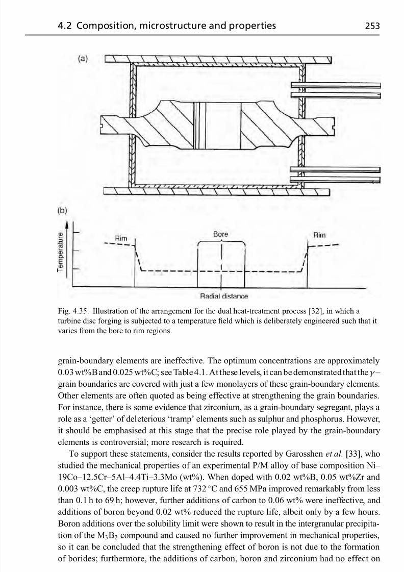
7/18/2019 The Superalloys Fundamentals and Applications
http://slidepdf.com/reader/full/the-superalloys-fundamentals-and-applications 271/389
4.2 Composition, microstructure and properties 253
Fig. 4.35. Illustration of the arrangement for the dual heat-treatment process [32], in which a
turbine disc forging is subjected to a temperature field which is deliberately engineered such that it
varies from the bore to rim regions.
grain-boundary elements are ineffective. The optimum concentrations are approximately
0.03wt%Band 0.025 wt%C; see Table4.1.At these levels, it can bedemonstrated that theγ –
grain boundaries are covered with just a few monolayers of these grain-boundary elements.
Other elements are often quoted as being effective at strengthening the grain boundaries.
For instance, there is some evidence that zirconium, as a grain-boundary segregant, plays a
role as a ‘getter’ of deleterious ‘tramp’ elements such as sulphur and phosphorus. However,
it should be emphasised at this stage that the precise role played by the grain-boundary
elements is controversial; more research is required.
To support these statements, consider the results reported by Garosshen et al. [33], who
studied the mechanical properties of an experimental P/M alloy of base composition Ni–
19Co–12.5Cr–5Al–4.4Ti–3.3Mo (wt%). When doped with 0.02 wt%B, 0.05 wt%Zr and
0.003 wt%C, the creep rupture life at 732 ◦C and 655 MPa improved remarkably from less
than 0.1 h to 69 h; however, further additions of carbon to 0.06 wt% were ineffective, and additions of boron beyond 0.02 wt% reduced the rupture life, albeit only by a few hours.
Boron additions over the solubility limit were shown to result in the intergranular precipita-
tion of the M3B2 compound and caused no further improvement in mechanical properties,
so it can be concluded that the strengthening effect of boron is not due to the formation
of borides; furthermore, the additions of carbon, boron and zirconium had no effect on

7/18/2019 The Superalloys Fundamentals and Applications
http://slidepdf.com/reader/full/the-superalloys-fundamentals-and-applications 272/389
254 Superalloys for turbine disc applications
Table 4.3. Alloy compositions
Target alloy compositions (wt%)
Alloy C Cr Co Mo Tl Al W Zr B Hf NI
Alloy 1(baseline Udimet 720) 0.025 16.0 14.75 3.0 5.0 2.5 1.25 0.035 0.02 — Bal
Alloy 2 0.025 16.0 14.75 3.0 5.0 2.5 1.25 0.035 0.02 — BalAlloy 3 0.025 16.0 14.75 3.0 5.0 2.5 1.25 0.035 0.03 0.75 BalAlloy 4 0.025 16.0 14.75 3.0 5.0 2.5 1.25 0.070 0.03 — BalAlloy 5 0.025 16.0 14.75 3.0 5.0 2.5 1.25 0.035 0.04 — Bal
Fig. 4.36. Fatigue crack propagation paths in the IN718 superalloy doped with (a) 12 ppm B and
(b) 29 ppm B [34]. Testing at room temperature in air, with R = 0.05.
the morphology of the γ phase. Moreover, the fatigue crack progagation rates at 649 ◦Cwere improved marginally, but by a factor of no greater than 2; this finding is consistent
with recent work on boron-doped IN718, which has demonstrated that the tortuosity of the
fatigue crack path was greatly increased as the level of boron doping was increased from
12 ppm to 29 ppm; see Figure 4.36 [34]. The effect on fatigue initiation as manifested in
the low-cycle-fatigue (LCF) life is very much more significant. Jain et al. [35] have doped
Udimet 720Li in P/M form with varying concentrations of boron to 0.04 wt%, at a constant
concentration of 0.025 wt%C; the effects of increasing the Zr concentration from 0.035
to 0.070 wt% and Hf from zero to 0.75 wt% were also studied. Testing was carried out at
both 425 ◦C and 650 ◦C, at two grain sizes corresponding to ASTM 11 and ASTM 9, which
were generated by sub- and super-solvus heat treatment, respectively. Un-doped Udimet
720Li in the cast-and-wrought condition was used as a control. The results are given inFigure 4.37 and Table 4.3. The results demonstrate that additions of the grain-boundary
elements are beneficial to LCF life; improvements of at least 50% were noted for most
conditions considered. Interestingly, the fatigue life for the fine-grained material (ASTM
11) was improved more substantially at 425 ◦C, whereas that for the coarse-grained material
improved at 650 ◦C; no explanation of this finding was offered. In this study, no substantial

7/18/2019 The Superalloys Fundamentals and Applications
http://slidepdf.com/reader/full/the-superalloys-fundamentals-and-applications 273/389
4.2 Composition, microstructure and properties 255
1 × 10⁴
2 × 10⁴
3 × 10⁴
4 × 10⁴
5 × 10⁴
6 × 10⁴
7 × 10⁴
8 × 10⁴
0
C y c l e s
t o f a t i g u e c r a c k i n i t i a t i o n
5.0 × 10³
0
1.0 × 10⁴
1.5 × 10⁴
2.0 × 10⁴
2.5 × 10⁴
3.0 × 10⁴
3.5 × 10⁴
C y c l e s t o f a t i g u e c r a c k i n i t i a t i o n 4.0 × 10⁴
4.5 × 10⁴
5.0 × 10⁴
C W U
7 2 0
A l l o y 1 ( S T D )
A l l o y 1 ( S T D )
A l l o y 2 ( S T D + 0 . 7 5 H f )
A l l o y 2 ( S T D + 0 . 7 5 H f )
A l l o y 3 ( S T D + 0 . 0 3 B )
A l l o y 3 ( S T D + 0 . 0 3 B )
A l l o y 4 ( S T D + 0 . 0 3 B + 0 . 0 7 Z r )
A l l o y 4 ( S T D + 0 . 0 3 B + 0 . 0 7 Z r )
A l l o y 5 ( S T D + 0 . 0 4 B )
A l l o y 5 ( S T D + 0 . 0 4 B )
C W U
7 2 0
A l l o y 1 ( S T D )
A l l o y 1 ( S T D )
A l l o
y 2 ( S T D + 0 . 7 5 H f )
A l l o
y 2 ( S T D + 0 . 7 5 H f )
A l l o y 3 ( S T D + 0 . 0 3 B )
A l l o y 3 ( S T D + 0 . 0 3 B )
A l l o y 4 ( S T D + 0 . 0 3 B + 0 . 0 7 Z r )
A l l o y 4 ( S T D + 0 . 0 3 B + 0 . 0 7 Z r )
A l l o y 5 ( S T D + 0 . 0 4 B )
A l l o y 5 ( S T D + 0 . 0 4 B )
Grain size: ASTM 9
Grain size: ASTM 11
(b)
(a)
Fig. 4.37. Data showing the influence of small amounts of B, Zr and Hf on the LCF performance of
the P/M U720Li turbine disc alloy [35]. LCF data at (a) 425 ◦C, cr = 0.9%, R = 0.0, air;
(b) 650 ◦C, cr = 0.8%, R = 0.0, air. Note that CW U720 refers to cast-and-wrought material.
For alloy compositions see Table 4.3.

7/18/2019 The Superalloys Fundamentals and Applications
http://slidepdf.com/reader/full/the-superalloys-fundamentals-and-applications 274/389
256 Superalloys for turbine disc applications
improvements in tensile properties were caused by the additions of the grain-boundary
strengtheners.
Blavette and co-workers have begun to unravel the scientific principles which gov-
ern the effects conferred by the grain-boundary elements [36]. Using a combination of
field-ion microscopy and atom probe tomography, the characterisation of B, C and Zr
grain-boundary chemistry in the P/M alloy N18 has been successfully attempted; see Fig-
ure 4.38. In this alloy, the bulk compositions of B, C and Zr are 0.083 at%, 0.075 at%
and 0.018 at%, respectively, but substantial segregation of B and Mo was demonstrated
at the γ/γ grain boundaries, where the local concentrations were enhanced ten-fold com-
pared to the bulk – equal to about 0.5 equivalent atomic monolayers. Incoherent γ/γ
boundaries were found to be similarly affected. Interestingly, no segregation of C was
identified; it is probable that in this alloy it resides primarily in chromium-rich M23C6
carbides. No segregation of Zr was found. Similar results were found in earlier work onAstroloy [37].
Case study. The design of turbine disc alloys
Most of the alloy development work for turbine disc superalloys has been carried out by
the engine manufacturers such as GE Aircraft Engines, Pratt & Whitney, SNECMA and
Rolls-Royce. The number of alloys which have been designed is relatively small, and due
to its proprietary nature it is unlikely that all details of the work have been revealed in the
open literature; nevertheless, some information has emerged. When designing the powder disc superalloy N18 in the mid-1980s, SNECMA placed considerable emphasis [38] on
promoting damage tolerance so that alloys with low-dwell fatigue crack propagation (FCP)
rates were preferred. It was noted that for many of the P/M alloys developed to that point,
such as Rene 95, IN100, MERL 76 and Astroloy, crack growth rates scaled with the yield
stress (see Figure 4.39); N18 was designed to fall away from this correlation, an order
of magnitude improvement in FCP rates being desired. For this alloy, an Ti/Al ratio of
unity, trace levels of B, C and Zr at 0.15, 0.15 and 0.30 wt%, respectively and a relatively
high concentration of Mo (6.5 wt%) were chosen [38]; it was claimed that Mo was more
favourable than W because of its greater γ/γ partitioning ratio and because it reduced
notch sensitivity during creep at 650 ◦C. The lack of damage tolerance displayed by Rene
95 was acknowledged by GE in designing their Rene 88DT superalloy (note ‘DT’ refers
to damage tolerant); significant improvements in these properties were made, with the
ultimate tensile strength (UTS) of Rene 88DT being kept within 90% of that of Rene 95
[39]. Dwell fatigue crack propagation rates at 650 ◦C were improved by increasing the γ
fraction and size, increasing the Ti/Al ratio and Ta substitution for W; however a trade-off
was identified which saw the high-volume-fraction γ alloys exhibiting very good dwell
FCP rates at 650 ◦C but poorer performance at 400 ◦C in the absence of a dwell period.Compared with Rene 95, the Rene 88DT composition was chosen to yield a smaller γ
fraction (40% rather than 50%), a higher Ti/Al ratio (1.8 rather than 0.7 on a wt% basis)
and higher Cr and Co contents (16 wt% rather than 13 wt%, and 13 wt% rather than 8 wt%,
respectively) – this last change being made despite substitutions of Co and Cr providing
no effect on dwell-time fatigue crack growth rate. The significant effect of Ta in reducing

7/18/2019 The Superalloys Fundamentals and Applications
http://slidepdf.com/reader/full/the-superalloys-fundamentals-and-applications 275/389
F i g . 4 . 3 8 . A n a l y s i s
u s i n g a t o m p r o b e t o m o g r a p h y
o f a γ / γ
g r a i n b o u n d a r y i n N 1
8 [ 3 6 ] : ( a ) , ( b ) , ( c ) a n d ( d ) c o r r e s p o n d t o m a p s o f
A l , C r , M o a n d B ; (
e ) a n d ( f ) a r e c o n c e n t r a t i o n p r o
fi l e s n o r m a l t o t h e b o u n d a r y a n
d ( g ) i s a fi e l d - i o n i m a g e ( F I M ) o f t h e g r a i n b o u n d a r y .

7/18/2019 The Superalloys Fundamentals and Applications
http://slidepdf.com/reader/full/the-superalloys-fundamentals-and-applications 276/389
258 Superalloys for turbine disc applications
10 10
MERL76
Astroloy
650 °C
IN100
Rene 95
Target
N18
1150
1100
1050
100010−3 10−2 10−12 5 2
da /dN (mm/cycle)
0 . 2
% y
i e l d s
t r e s s
( M P a
)
5
300
Stress
Time (s)
Fig. 4.39. Variation of the yield stress with dwell fatigue crack growth rate for a number of P/M
superalloys [38].
dwell FCP rates has been noted in collaborative work by Pratt & Whitney, GE and NASA,
which was aimed at developing an alloy for the High Speed Civil Transport (HSCT) aero-
plane [40]; this gave rise to the alloy ME3, which has a significant Co concentration tolower the γ solvus temperature so that the risk of thermally induced porosity (TIP) is
minimised, with the heat treatment window being widened to enable super-solvus heat
treatment and dual microstructure heat treatments; see Table 4.1. Alloy ME3 is similar to
Rene 104, which will find use in the General Electric’s GEnx engine for the Boeing 787
Dreamliner. An addition of Ta to Rolls-Royce’s RR1000 powder disc superalloy was made
for similar reasons as for ME3 [41], although the concentration was limited to 2.15wt%
since the FCP rates increased for higher concentrations of this element. Chromium was
found to reduce the rate of FCP at elevated temperature, but its concentration was lim-
ited to 15 wt% because it promotes the precipitation of the σ phase, particularly above
700 ◦C. The importance of restricting the Cr concentration was learned by Special Metals
Corporation during the Udimet 720 development programme [16] – the original compo-
sitional variant contained 18 wt%Cr, but in developing the second variant, Udimet 720Li,
this was reduced to 16 wt%Cr, which has been shown to improve the susceptibility to σ
formation [42]; moreover, the boron and carbon levels were reduced (Li refers to ‘low
interstitial’) to about 0.025 wt% and 0.018 wt%, respectively, concentrations which ap-
pear to have been agreed upon by the superalloy community in at least an approximate
sense; see Table 4.1. More recently, NASA has developed a hybrid disc alloy, LSHR, whichcombines the low solvus temperature of Rene 104 with the higher refractory content of
Alloy 10, the latter being designed by Honeywell Engines and Systems to produce su-
perior tensile and creep capability in small engines for auxiliary power unit (APU) ap-
plications; this was achieved by using a high refractory element content, most notably of
tungsten.

7/18/2019 The Superalloys Fundamentals and Applications
http://slidepdf.com/reader/full/the-superalloys-fundamentals-and-applications 277/389
4.3 Service life estimation 259
Fig. 4.40. Illustration of the stress field (solid lines) in a uniform disc of outer radius b, with a hole
of radius a; σ θ and σ r denote the hoop and radial stress, respectively. Also shown (dashed lines) is
the behaviour of σ θ and σ r for the case when a = 0, i.e. when no hole exists.
4.3 Service life estimation for turbine disc applications
4.3.1 Stress analysis of a turbine disc of simplified geometry
A geometry of a typical turbine disc is complicated by the requirement for fixturing to
accommodate the turbine blading, the drive arms necessary to transmit loads to the shaft,
cover plates to manage the flow of cooling air and flanges with holes for the bolting together
of neighbouring discs. Moreover, the shape of the disc is generally tapered to restrict the
stress field at the bore to manageable levels. However, to gain a first appreciation of the very
large stresses to which the material is subjected, one can consider a cylindrical component
of outer diameter b containing a hole of inner radius a, rotating at an angular velocity ω.
The density is ρ. Clearly the stress field will depend upon whether the component is thin
(such that it approximates a disc) or thick (in which case it is a cylinder). Considering the
situation for a disc under plane stress conditions – and given the simplifying assumptions – the radial and hoop components of the stress field, denoted σ r and σ θ , respectively, are given
by [43,44]
σ r =3+ ν
8ρω2
b2 + a2 − a2b2
r 2− r 2
(4.2)
and
σ θ =3+ ν
8ρω2
b2 + a2 + a2b2
r 2−
1+ 3ν
3
+ν r 2 (4.3)
where the distance r is measured outwards from the axis of symmetry in a radial direction.
It is instructive to consider the stress field implied by these equations; see Figure 4.40.
The hoop stress, σ θ , is a maximum at the bore where r = a, where it takes a value of
(σ θ )max =
3+ ν
4
ρω2b2 +
1− ν
4
ρω2a2 (4.4)

7/18/2019 The Superalloys Fundamentals and Applications
http://slidepdf.com/reader/full/the-superalloys-fundamentals-and-applications 278/389
260 Superalloys for turbine disc applications
Furthermore, σ θ increases monotonically with decreasing r , due to the mass of material
between r = a and r = b which requires support. The radial stress, σ r , falls to zero at
the free surfaces corresponding to the bore and rim, where r = a and r = b, respectively,
but rises to a maximum value between the two. That the hole provides a considerable
stress concentration factor can be seen by setting a = 0 in Equations (4.2) and (4.3). Then,
σ θ and σ r are equivalent at r = 0, when σ r = σ θ = (3+ ν)ρω2b2/8. A comparison with
Equation (4.4) indicates that the stress concentration factor introduced by the hole is at least
2, and greater than this value if the second term in Equation (4.4) is significant.
Values for σ r and σ θ canbe estimated. With b = 33cm, a = 7.5cm,ω = 10 000 rev/min,
ρ = 8900kg/m3 and ν = 0.3, the hoop stress, σ θ , has a maximum value of about 885MPa
at the bore where r = a. The stresses are very much greater for larger discs – Equation (4.4)
indicates that for constant aspect ratio b/a, the bore stress scales as the square of the linear
dimensions; consequently, larger engines must spin at a proportionately smaller rate. For example, if the linear dimensions are doubled at constant b/a, then ω must be halved
for an equivalent stress field. These considerations confirm that materials with high-yield
stresses are required for turbine-disc applications, and that the geometry needs to be chosen
carefully such that the stress levels are restricted to tolerable levels. However, the level of
conservatism in component design cannot be too great, otherwise excessive parasitic weight
will be introduced.
4.3.2 Methods for lifing a turbine disc The manufacture of a turbine disc calls for great care to be taken to avoid the introduction
of defects. To see why this is the case, it is instructive to consider three common lifing
methods.
A The life-to-first-crack approach
In the life-to-first-crack approach, which is used in the United Kingdom, current require-
ments stipulate that fracture critical components such as an HP turbine disc are treated
according to a safe-life policy in which component ‘failure’ is defined as the occurrence
of an engineering crack of surface length 0.75 mm [45,46]. This figure is below the length
required for fast catastrophic fracture, and is chosen because it is about the limit of common
non-destructive inspection (NDI) methods. Reliance is placed on the testing of real discs
in spin rigs, under stress and temperature conditions comparable to those experienced in
service. Each test can cost between $250 000 and $500 000; consequently, the number of
tests is small – it is rare for this to exceed five.
For the purposes of declaring a safe service life, it is assumed that (i) the number of
cycles to failure is distributed according to a log-normal density function, and (ii) to a 95%confidence level, not more than 1 in 750 discs are expected to contain a crack of surface
length greater than 0.75 mm [47,48]; thus one is working at the 1/750 quantile (−3σ ) such
that the ratio of the fatigue lives at the +3σ and −3σ points is 6; see Figure 4.41. Given
this assumed scatter factor, the life corresponding to the lower 1/750 quartile is located
at a factor of √
6 below the geometric mean obtained from the spin testing. This lower

7/18/2019 The Superalloys Fundamentals and Applications
http://slidepdf.com/reader/full/the-superalloys-fundamentals-and-applications 279/389
4.3 Service life estimation 261
S t r e s s ,
σ
Number of cycles, N
Meancurve
62.451
+ 3σcurve
Assumed location of
test component
Predicted safecycle life, Ar
−3σ curve
5% of components
Fig. 4.41. Distribution of fatigue failure events superimposed on a σ − N plot with the mean, +3σ
and −3σ values identified [47].
confidence bound translates to a factor of
61.645/6√
n (4.5)
where the 95% confidence limit corresponds to 1.645 standard deviations. This procedureallows a so-called ‘safe life’ to be calculated from the expression
safe life =n
i=1 N i1/n
2.449× 6
1.6456√
n
(4.6)
The denominator in the above equation, i.e. the factor by which the ‘safe life’ is lower than
the geometric mean of the results from spin testing, is 4.00 when n = 1, falling to 3.25 when
n = 3 and 2.90 when n = 8 – thus, a safety factor is present, the magnitude dependent upon
the number of components tested.
Note that the use of the ‘first crack’ as the basis for the calculation will be conservative,
since the length of a surface crack which will burst the disc is usually likely to be in excess
of 0.75 mm. This provides a further built-in margin of safety.
B Damage-tolerant lifing
In practice, the ‘extra’ safety factor arising from the choice of a 0.75 mm long crack as
constitutingfailure creates a dilemma.Precisely how large is it?If it is toolarge theprocedure
will be wildly conservative. It could, however, be very small or non-existent. Thus, in someways the life-to-first-crack approach is unsatisfactory.
The ‘damage-tolerant’ approach to disc lifing (known alternatively as the ‘retirement
for cause’ method) represents an alternative strategy [47,48]. One starts by estimating the
length of crack required for ‘burst’, i.e. for fast catastrophic fracture, by using a fracture
mechanics approach. Next, the number of cycles is estimated for the fatigue crack to grow

7/18/2019 The Superalloys Fundamentals and Applications
http://slidepdf.com/reader/full/the-superalloys-fundamentals-and-applications 280/389
262 Superalloys for turbine disc applications
Table 4.4. Crack length data [48] relating to fast fracture and fatigue crack propagation
in turbine disc alloys, with the stress range, σ , assumed equal to the proof strength
Stress range σ /MPa
(assumed = 0.2% proof strength) a NDI/mm a(3300)/mm a(6700)/mm acrit(10 000)/mm
800 0.30 0.50 1.20 11.1850 0.23 0.40 0.97 9.8950 0.13 0.23 0.58 7.91000 0.10 0.18 0.46 7.11200 0.04 0.08 0.20 4.9
Note: In the last column, the crack length, acrit, at fast fracture is given, assuming Y = 0.67 and K 1c equal to 100 MPa m1/2 and a stress equal to the proof strength. In the other columns are giventhe crack lengths at initiation (which is equivalent to the required non-destructive inspection limit
a NDI), one-third and two-thirds dysfunction, assuming that failure occurs at 10 000 cycles.
from the limit of the non-destructive inspection techniques, a NDI, to the size required for
burst, acrit. Fatigue-crack propagation data in the form of d a/d N data are required for this
purpose, and this usually conforms to the usual Paris law expression
d a
d N = A K m (4.7)
where K is therangeof stressintensityexperiencedby thecrack.Theexponentm is usually
between 3 and 4 for superalloys. Upon inserting the expression for K = Y σ √ πa, and after performing the appropriate integration, one has
N 0 =1
A(m/2− 1)Y mσ mπm/2
1
am/2−1
NDI
− 1
am/2−1crit
(4.8)
where N 0 is the number of cycles for failure.
It is instructive to plug in some numbers, following Knott [48]. For many of the polycrys-
talline nickel-based superalloys used for turbine disc applications, the Paris relationship is
of the formd a
d N = 4× 10⁻¹² K 3.3 (4.9)
where K is expressed in MPa m1/2 and d a/d N is the growth increment per cycle ex-
pressed in metres. Assuming a semicircular edge crack, Y = 0.67. For most nickel-based
superalloys, the fracture toughness, K 1c, is about 100 MPa m1/2; if we assume σ is equal
to 800 MPa, with failure occurring at the top of the cycle, one obtains acrit = 11 mm. Next,
one can determine an appropriate limit for a NDI if one requires the turbine disc to last for
at least 10 000 cycles – a figure of 0.30 mm is found. This is not very much smaller thanthe value assumed for the ‘first crack’ in the life-to-first-crack approach. The values of a at
3300 and 6700 cycles, corresponding to one-third and two-thirds dysfunction, respectively,
are 0.50 mm and 1.20 mm; see Table 4.4 [48]. Note that the majority of the fatigue crack
growth occurs in the last few thousand cycles. In practice, one should note that estimates of
the fatigue life made in this way are usually conservative, since no account has been taken of

7/18/2019 The Superalloys Fundamentals and Applications
http://slidepdf.com/reader/full/the-superalloys-fundamentals-and-applications 281/389
4.3 Service life estimation 263
C r a c
k s
i z e N
u c
l e a t i o
n
Shortcrackgrowth
Crack growthdefined by K
Life
Final fracture
Fig. 4.42. Illustration of the different stages associated with fatigue crack failure: initiation, short
crack growth, fatigue crack propagation and final fracture governed by the fracture toughness.
Fig. 4.43. Schematic representation of the damage-tolerant life prediction method [49].
the number of cycles required for fatigue crack growth to be initiated; see Figure 4.42. After
the disc has operated for an appropriate number of cycles, it undergoes thorough inspection
using the NDE techniques which would have been first employed before the disc entered service; provided that this reveals that no flaws are present, it is placed back into the en-
gine for a further number of cycles. Figure 4.43 illustrates this so-called ‘damage-tolerant’
method [49].
It is helpful to make estimates of the safety margins to be expected from the use of
nickel-based alloys of differingproof strengths, following the analysispresented in ref. [48].
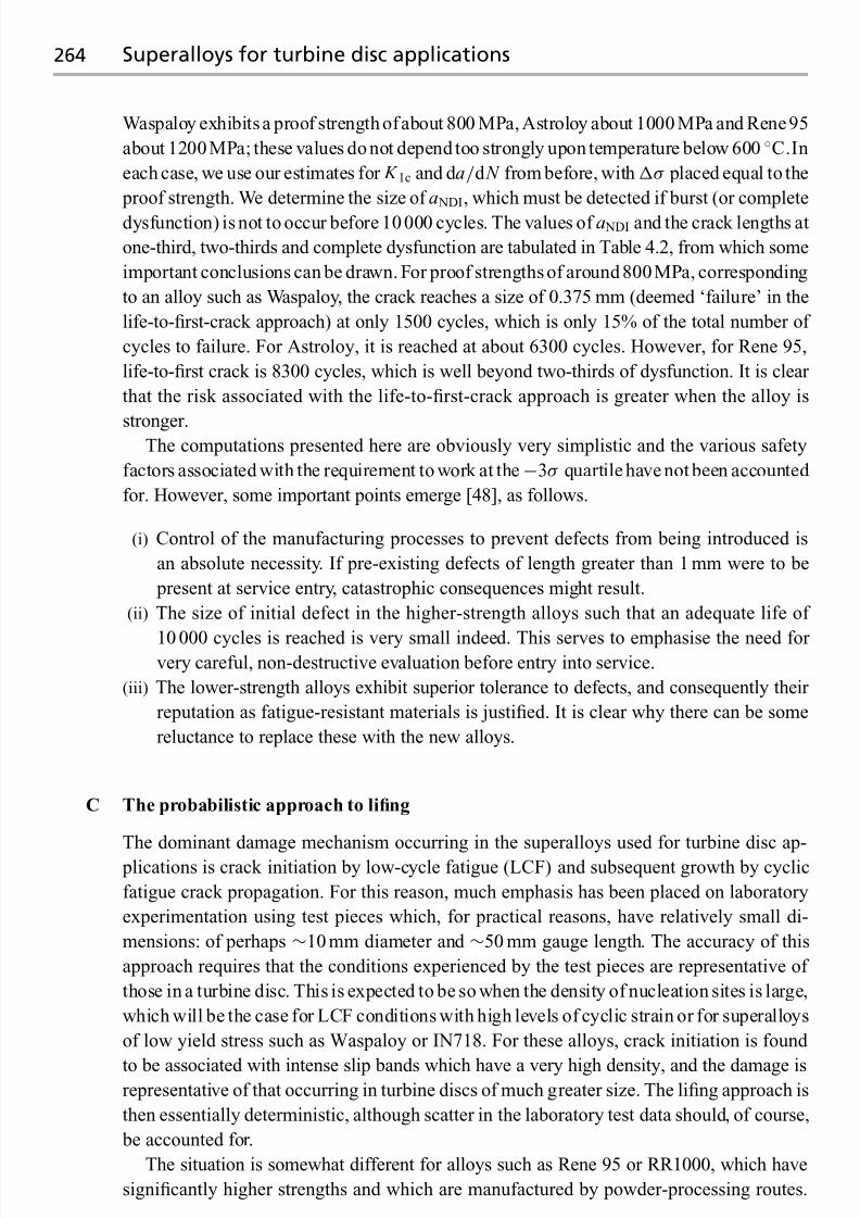
7/18/2019 The Superalloys Fundamentals and Applications
http://slidepdf.com/reader/full/the-superalloys-fundamentals-and-applications 282/389
264 Superalloys for turbine disc applications
Waspaloy exhibits a proof strength ofabout 800 MPa,Astroloy about 1000 MPa and Rene95
about 1200MPa; these values do not depend too strongly upon temperature below 600 ◦C.In
each case, we use our estimates for K 1c andd a/d N from before, withσ placed equal to the
proof strength. We determine the size of a NDI, which must be detected if burst (or complete
dysfunction) is not to occur before 10 000 cycles. The values of a NDI and the crack lengths at
one-third, two-thirds and complete dysfunction are tabulated in Table 4.2, from which some
important conclusions can be drawn. For proof strengths of around 800MPa, corresponding
to an alloy such as Waspaloy, the crack reaches a size of 0.375 mm (deemed ‘failure’ in the
life-to-first-crack approach) at only 1500 cycles, which is only 15% of the total number of
cycles to failure. For Astroloy, it is reached at about 6300 cycles. However, for Rene 95,
life-to-first crack is 8300 cycles, which is well beyond two-thirds of dysfunction. It is clear
that the risk associated with the life-to-first-crack approach is greater when the alloy is
stronger.The computations presented here are obviously very simplistic and the various safety
factors associated with the requirement to work at the−3σ quartile have not been accounted
for. However, some important points emerge [48], as follows.
(i) Control of the manufacturing processes to prevent defects from being introduced is
an absolute necessity. If pre-existing defects of length greater than 1 mm were to be
present at service entry, catastrophic consequences might result.
(ii) The size of initial defect in the higher-strength alloys such that an adequate life of
10 000 cycles is reached is very small indeed. This serves to emphasise the need for very careful, non-destructive evaluation before entry into service.
(iii) The lower-strength alloys exhibit superior tolerance to defects, and consequently their
reputation as fatigue-resistant materials is justified. It is clear why there can be some
reluctance to replace these with the new alloys.
C The probabilistic approach to lifing
The dominant damage mechanism occurring in the superalloys used for turbine disc ap-
plications is crack initiation by low-cycle fatigue (LCF) and subsequent growth by cyclic
fatigue crack propagation. For this reason, much emphasis has been placed on laboratory
experimentation using test pieces which, for practical reasons, have relatively small di-
mensions: of perhaps ∼10 mm diameter and ∼50 mm gauge length. The accuracy of this
approach requires that the conditions experienced by the test pieces are representative of
those in a turbine disc. This is expected to be so when the density of nucleation sites is large,
which will be the case for LCF conditions with high levels of cyclic strain or for superalloys
of low yield stress such as Waspaloy or IN718. For these alloys, crack initiation is found
to be associated with intense slip bands which have a very high density, and the damage isrepresentative of that occurring in turbine discs of much greater size. The lifing approach is
then essentially deterministic, although scatter in the laboratory test data should, of course,
be accounted for.
The situation is somewhat different for alloys such as Rene 95 or RR1000, which have
significantly higher strengths and which are manufactured by powder-processing routes.
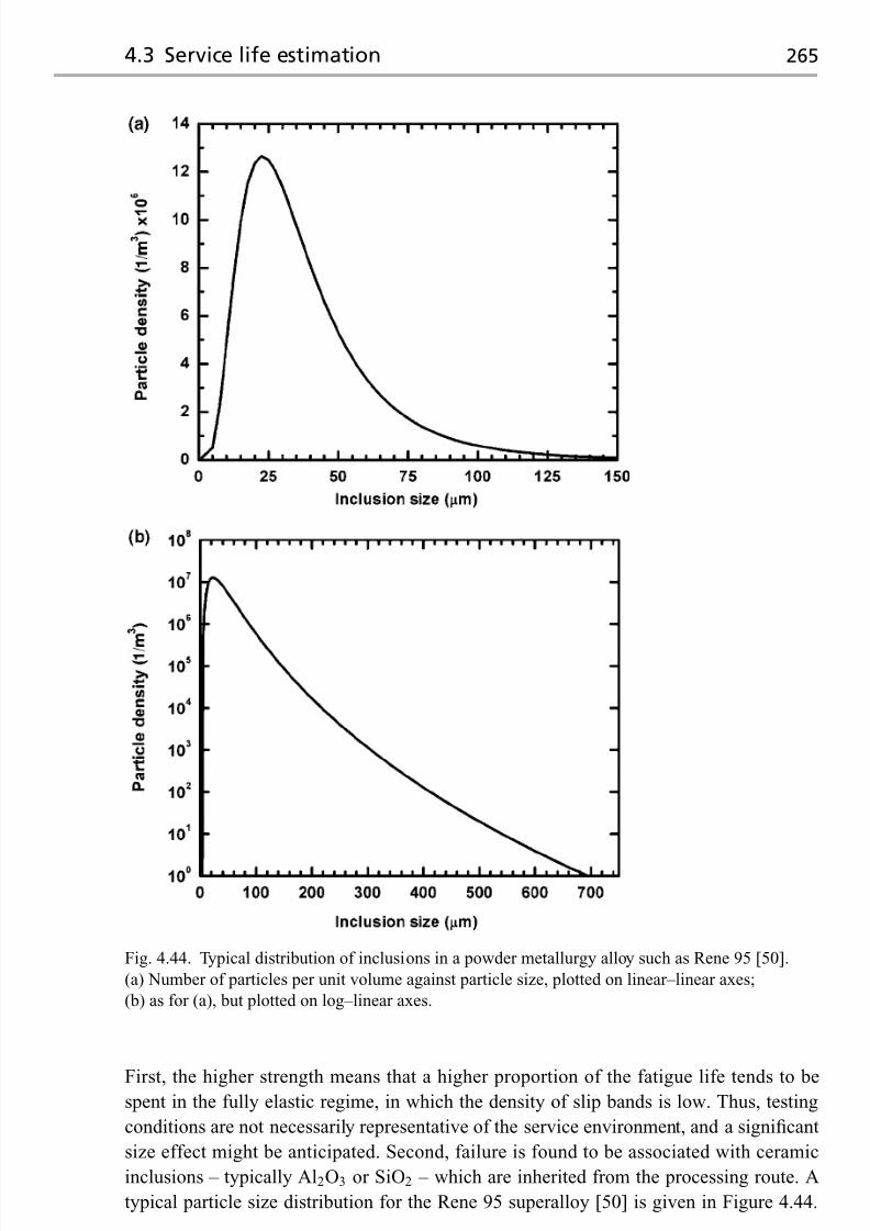
7/18/2019 The Superalloys Fundamentals and Applications
http://slidepdf.com/reader/full/the-superalloys-fundamentals-and-applications 283/389
4.3 Service life estimation 265
Fig. 4.44. Typical distribution of inclusions in a powder metallurgy alloy such as Rene 95 [50].
(a) Number of particles per unit volume against particle size, plotted on linear–linear axes;
(b) as for (a), but plotted on log–linear axes.
First, the higher strength means that a higher proportion of the fatigue life tends to bespent in the fully elastic regime, in which the density of slip bands is low. Thus, testing
conditions are not necessarily representative of the service environment, and a significant
size effect might be anticipated. Second, failure is found to be associated with ceramic
inclusions – typically Al2O3 or SiO2 – which are inherited from the processing route. A
typical particle size distribution for the Rene 95 superalloy [50] is given in Figure 4.44.

7/18/2019 The Superalloys Fundamentals and Applications
http://slidepdf.com/reader/full/the-superalloys-fundamentals-and-applications 284/389
266 Superalloys for turbine disc applications
1
0.5 Δ ε t / 2 ( % )
102 103 104
Cycles to failure
105
P/M Rene 95 LCF 538 °C
Surface inclusion initiation band
Internal inclusion initiation band
Fig. 4.45. Results from LCF fatigue tests on the powder metallurgy alloy Rene 95. Also indicated
are the positions of the inclusions causing failure [51].
Although their density is very low – a fraction of less than 10−6 is typical – the frequency
of their occurrence is sufficient to cause considerable scatter in the fatigue data. Figure 4.45
shows typical LCF data for Rene 95 [51]; note, in particular, the greater scatter at lower cyclic strains. Furthermore, in such tests it is found that inclusions at the free surfaces are
very much more detrimental than inclusions initiating cracks at depth. These considerations
emphasise the need for a statistical, or probabilistic, approach, as the fatigue performance
now depends upon the surface area and volume of material being loaded. Larger volumes
of material will perform more poorly than smaller ones, owing to the greater probability of
an inclusion of greater size being present.
Pineau and co-workers have put these considerations onto a quantitative basis, and what
follows is an analysis of the approach proposed in ref. [50]. Consider a volume, V , of
material which has a surface area, S , exposed to a cyclic stress, σ , with R = 0. Assume
that uniform spherical inclusions of diameter D are present at a density nv per unit volume.
The probability of any single inclusion avoiding the surface depends upon the surface
to volume ratio, S /V ; to a first approximation, it is given by the quantity 1− DS /V , if
stereological effects associated with the intersection of the particle with the free surface are
neglected. However, a total of (nv × V ) inclusions arepresent. It follows that theprobability,
p1, of any one inclusion intersecting the free surface is given by
p1{ D} = 1−
1− DS V
nvV
(4.10)
It is necessary also to acknowledge the manner in which any given inclusion interacts
with the free surface; for example, a fully embedded inclusion is clearly more damaging
than one which is only partially embedded to depth d , where d < D. If the flaw size, d ,
defines a fatigue life, N 0, consistent with the damage-tolerant approach described above,

7/18/2019 The Superalloys Fundamentals and Applications
http://slidepdf.com/reader/full/the-superalloys-fundamentals-and-applications 285/389
4.3 Service life estimation 267
500000
450000
400000
350000
300000
N p
( n u m b e r o f c y c l e s )
Normalised flaw size, d / D
250000
200000
150000
100000
50000
00.0 0.2 0.4 0.6 0.8 1.0
10 µm
20 µm
30 µm
90 µm
Fig. 4.46. Variation of the predicted life with the flaw size, d , normalised against the inclusion
diameter, D, for various values of D.
the probability, p2, that the actual life is N p such that N p < N 0 is
p2
N p < N 0
=
1−
1− DS
V
nvV
D − d
D
(4.11)
The term ( D − d )/ D should be considered to be a ‘harmfulness criterion’, which acknowl-
edges that, when d = D, the inclusion is at its most potent; then N p = N 0 and p2 = 0. At
the other extreme, when the inclusion only just intersects the free surface, d = 0, and there-
fore it is not damaging; hence p2 = p1. In this limit, the N p tends to infinity. Figure 4.46
illustrates the way in which N p varies with d / D, for the various sizes of inclusion D implied
by the particle size distribution in Figure 4.44. Note that as d / D tends to zero, an infinite
life is expected since flaws are then absent.
In practice, a superalloy turbine disc material contains a distribution of particle sizes,
and this must be accounted for. Suppose that the particle size distribution is discretised
such that is contains nclasses classes, each of diameter Di and number density niv , such that
i = 1 → nclasses. The probability, p3, that the life, N p, is less than the potential life N 0 is
then given by
p3{ N p < N 0} = 1−nclasses
i=1
[1− p4{ N p < N 0}] (4.12)
where, by appealing to the expression for p2, one has
p4{ N p < N 0} =
1−
1− Di S
V
nivV
Di − d
Di
(4.13)

7/18/2019 The Superalloys Fundamentals and Applications
http://slidepdf.com/reader/full/the-superalloys-fundamentals-and-applications 286/389
268 Superalloys for turbine disc applications
Fig. 4.47. Variation of the probability of failure, given by p3, against the number of cycles, N 0, for
the probabilistic model of Rene 95.
Note that the product in the expression for p3 represents the probability that every class of
inclusion, Di , in the set of nclasses is non-damaging; p3 is then the probability that any one
of the Di provides the fatal flaw.
With this model, quantitative calculations can be carried out in the following way. First,
the variation of N 0 with flaw size, d , is determined using the damage-tolerant approach
described in the previous section. Data for K 1c, σ and the constants in the Paris law are
required. Second, the data for d are normalised against the Di present in the particle size
distribution, and a family of curves is produced which describes the variation of the life,
N p, with d / Di , as in Figure 4.46. Third, a prescribed life, N 0, is chosen; this defines d , and
hence d / Di, for any given D
iso that a set of values for p
4can be determined from the
expression given, each for a corresponding Di . This allows a value for p3 to be calculated.
The process can be repeated for various values of N 0 and σ ; see Figure 4.47, in which N 0
is plotted against p3, the probability that the life falls short of N 0.
The results in Figure 4.47 – calculated for the Rene 95 superalloy withσ = 1000 MPa,
Y = 0.67, the constants for the Paris equation given in the previous section and the particle
size distribution given in Figure 4.44 – demonstrate that the fatigue performance displays
a considerable dependence upon the surface area of the volume under load. For a large
disc of surface area 84 000mm2 and volume 10−2 m, the probability of failure varies from
less than 0.01 for fewer than 5000 cycles, to greater than 0.99 beyond 20 000 cycles. Asmaller disc of surface area 9300mm2 and volume 3× 10⁻³ m, or else a standard fatigue
test specimen of surface area 200 mm2 and volume 3.5× 10⁻⁶ m, exhibit considerably
superior performance. At any given probability of failure, the model indicates that the in-
clusion which is the likeliest to cause failure has a size which depends upon the surface
to volume ratio. For example, a test specimen is predicted to fail from an inclusion at

7/18/2019 The Superalloys Fundamentals and Applications
http://slidepdf.com/reader/full/the-superalloys-fundamentals-and-applications 287/389
4.3 Service life estimation 269
Fig. 4.48. Variation of the probability, p4, with inclusion size, Di , at a probability p3 equal to 0.01,
for the three geometries considered in the probabilistic model for Rene 95. The applied stress is
1000MPa.
the lower end of the particle size distribution, whereas a turbine disc of reasonable size
fails from an inclusion of greater size; see Figure 4.48. This is a direct consequence of a particle-sampling effect – a large particle (which has a low likelihood of occurrence)
has a greater probability of causing failure when the surface area is significant. The sen-
sitivity of the fatigue life to the particle size distribution has been confirmed [52] using
low-cycle-fatigue (LCF) tests on powder-processed Udimet 720, and the results have been
compared with those from the same material that had been intentionally doped with alu-
mina particles of sizes 54 μ m and 122 μ m. The results (see Figure 4.49) indicate that the
fatigue life is indeed impaired as the particle size increases; the reduction in life is great-
est for lower total strain ranges and larger R-ratios. Figure 4.50 illustrates the results of
fractography to identify the location of fatigue initiation in a typical turbine disc alloy.
In principle, such experiments can be used to deduce the naturally occurring particle size
distributions from the fatigue data of unseeded material – as required by the probabilistic
modelling.
The above considerations justify the considerable emphasis which is placed by the su-
peralloy industry on ‘superclean melting technology’ – the aim of which is to prevent non-
metallic inclusions from becoming incorporated into superalloy forging stock and hence
the turbine discs themselves. It is common nowadays for the rate of contamination to be
less than one part per million on a weight per cent basis. Nevertheless, when using a prob-abilistic lifing method it is absolutely necessary to have a good estimate of the particle
size distribution; the accuracy of the fatigue life depends upon it and, indeed, no estimate is
possible if this is unavailable. To glean the necessary information, different approaches have
been employed. Quantitative metallography has been used to examine plane, polished cross-
sections. However, for ‘superclean’material this canbe problematical, since the numberand

7/18/2019 The Superalloys Fundamentals and Applications
http://slidepdf.com/reader/full/the-superalloys-fundamentals-and-applications 288/389
270 Superalloys for turbine disc applications
0.014
0.012
0.010
0.008
0.006
Life cycles
0.004
0.002
0.000102 103 104 105 106 107 108
Unseeded R = −1
54 μm inclusions R = −1
122 μm inclusions R = −1 S t r a i n r a n g e
( m m
/ m m
)
0.014
0.012
0.010
0.008
0.006
Life cycles
0.004
0.002
0.000102 103 104 105 106 107 108
S t r a i n r a n g e
( m m
/ m m
)
0.014
0.012
0.010
0.008
0.006
Life cycles
0.004
0.002
0.000102 103 104 105 106 107 108
S t r a i n r a n g e
( m m
/ m m
) Unseeded R = 0.5
54 μm inclusions R = 0.5
122 μm inclusions R = 0.5
Unseeded R = 0
54 μm inclusions R = 0
122 μm inclusions R = 0
Fig. 4.49. Comparison of the LCF lives of powder metallurgy Udimet 720 in the unseeded and
seeded conditions, for various R ratios [52].

7/18/2019 The Superalloys Fundamentals and Applications
http://slidepdf.com/reader/full/the-superalloys-fundamentals-and-applications 289/389
4.3 Service life estimation 271
Fig. 4.50. Fatigue initiation site for powder metallurgy Udimet 720 seeded with 54μ m diameter
inclusions, LCF tested at 427 ◦C under strain control with a range of 1.2%, R
= −1 [52]. Surface
initiation is apparent.
size of inclusions is very small, possibly to an extent which makes the work prohibitively
time-consuming and expensive. This is confirmed by the data in Figure 4.51, which shows
the cross-sectional area of material to be examined in order to obtain an estimate of the vol-
ume fraction of inclusions to an accuracy greater than 20%, with 80% confidence [53]; for a
diameter of 100 μ m and a volume fraction of 10−6, the surface area required is ∼106 mm2,
or one square metre. These difficulties have provided the incentive for the development of
the electron beam button melting (EBBM) technique, in which about 1 kg of the alloy isdrip-melted under vacuum by an electron beam; the inclusions rise to the surface of the
pool (since they are lighter than the molten liquid), where they are subject to buoyancy and
Marangoni forces. If the cooling is then properly controlled, the inclusions concentrate into
the last portion to solidify, which then allows them to be analysed. The EBBM techique has
shown some promise, although it has been criticised on the grounds that it does not provide
an accurate measure of the distribution of particle sizes, since the flotation efficiency is a
function of the particle size.
4.3.3 Non-destructive evaluation of turbine discs
It has been shown in Section 4.3.2 that the flaws in a turbine disc are of great signifi-
cance; since they represent potential sites for the nucleation of cracks, they threaten the
integrity of the component and reduce the fatigue life. For this reason, much emphasis is

7/18/2019 The Superalloys Fundamentals and Applications
http://slidepdf.com/reader/full/the-superalloys-fundamentals-and-applications 290/389
272 Superalloys for turbine disc applications
Volume fraction
106
10−6
105
10−5
104
10−4
103
10−3
102
10−2
101
10−11
S u r f a c e a r e a e x a m i n e d ( m
m 2 )
Inclusiondiameter
1000 μm
200
100
50
20
500
10
Fig. 4.51. Variation of the surface area which
must be examined with volume fraction and
diameter of inclusions, at the 80% confidence
limit [53].
placed on using non-destructive evaluation (NDE) to characterise the dimensions of the
flaws, both during the manufacturing of the turbine disc – i.e. before the turbine disc enters
service for the first time – to ensure that it is of acceptable quality, and then whenever
the disc is removed from the engine, prior to a decision being made to place it back in
service. Obviously, the first situation arises regardless of the lifing method employed, the
second only when the damage-tolerant method is being used. The various NDE meth-
ods which are suitable include (i) the liquid penetrant method, most usually using dyes
which fluoresce under ultra-violet light, thus providing a measure of the length of each
crack exposed to the surface; (ii) the eddy current method, which enables a quantitative
estimate of the crack depth, but only for cracks located at or near the surface; (iii) X-ray
radiography, which has the power to penetrate relatively thick sections, but which cannot
usually resolve the finest flaws that are present; and (iv) ultrasonics – the use of high-frequency sound waves for the detection of inclusions, coarse grains, shrinkage pipe, tears,
seams and laps. In practice, for turbine disc applications this final method is of the greatest
importance.
To illustrate the use of ultrasonics [54] for NDE in this context, consider its application to
a forged and heat-treated disc, which will have been machined to a pre-specified geometry
known as the ‘sonic shape’ or ‘condition of supply’. To enable ease of ultrasonic inspection,
the features of the disc (for example, the blade root sockets, cover plate and flanges) are not
introduced by the machining process as yet, so that, at this stage, it contains only a few, flat
surfaces which intersect at 90◦ angles; see Figure 4.52. To detect the smallest flaws, careis taken also with the surface finish, which is typically better than 6 μ m. Production and
measurementof theultrasonic waves is accomplishedviatheuseofpiezoelectric transducers
and receivers – these rely upon crystals, such as quartz or barium titanate, which display a
strong inverse piezoelectric effect. Since ultrasonic waves are attenuated strongly by air, the

7/18/2019 The Superalloys Fundamentals and Applications
http://slidepdf.com/reader/full/the-superalloys-fundamentals-and-applications 291/389
4.3 Service life estimation 273
Forgingoutline
Inspectionenvelope
Finished discoutline
Fig. 4.52. Schematic illustration of the outline
of a machined turbine disc, the sonic envelope
used to test the material ultrasonically and the
forging from which it is machined.
disc and transducer are either kept immersed in water during inspection, or else a thin layer of coupling fluid is maintained between the two; the waves are attenuated only very weakly
by the material itself, so that very thick sections can be analysed. In practice, the waves
are sent through the component in at least two different ways. First, the so-called ‘straight-
beam top inspection’ is carried out to detect planar flaws lying parallel to surfaces whose
normal lies parallel to the axis of the forging; for this purpose, a longitudinal ultrasonic
beam is directed parallel to the normal to these same surfaces, using a single pulse-echo
transducer, 13–40 mm in diameter, at a frequency in the range 1–5 MHz. Calibration is
carried out using standard 50 mm diameter cylindrical reference blocks of varying heights,
into which flat-bottomed holes are machined to simulate artificial flaws of different sizes
located at different depths. Detection sensitivity is normally set to 10% of the size of
the flaw machined into the calibration block. For example, if the #2 block in Series B
of the ASTM standard E127 is found to be suitable for calibration [55], the expected
sensitivity of flaw detection is then 0.08 mm since the flat-bottomed hole in that case has
a diameter of 0.8 mm. A second set of tests are conducted using shear waves, to detect
flaws that have an axial radial orientation; for this, an angle-beam transducer is used to
introduce a beam at 45◦ to the surface normal, and inspection is performed by scanning in
thecircumferentialdirection, both clockwiseandanti-clockwise, aroundtheperipheryof theforging. Calibration notches – typically 25mm long and either V-shaped or rectangular – are
cut axially onthe inner and outer surfacesof the forging,witha width not exceeding twice the
depth.Thesensitivityof thedetection is establishedbyfirst adjusting the instrumentcontrols
to obtain a minimum 13 mm sweep-to-peak signal from the calibration notch on the outer
surface, followed by a measurement of the response from the notch on the inside surface;
the peaks corresponding to the two notches are connected thus establishing a reference
line.
With regard to the inspection of different superalloys, the background noise is found
to be significantly greater for coarse-grained material, and therefore the sensitivity of flaw detection is then much reduced; small flaws are then more likely to be undetected.
The data given in Table 4.5 illustrate this [56]. Interestingly, for any given grain size,
powder metallurgy (P/M) material exhibits ultrasonic inspectability which is very much
better than for conventional cast-and-wrought product. This has been attributed to the

7/18/2019 The Superalloys Fundamentals and Applications
http://slidepdf.com/reader/full/the-superalloys-fundamentals-and-applications 292/389
274 Questions
Table 4.5. Data for the inspectability of the Udimet 720 superalloy for various grain
sizes, in the powder and cast-and-wrought conditions [56]
Form Billet diameter /mm Grain diameter /μ m Noise level
Powder metallurgy, extruded 150–300 3 6% at hole 1a
Powder metallurgy, sub-solidusHIP + cog 300 11 25% at hole 1
Powder metallurgy, HIP 165 11 15% at hole 1Powder metallurgy, sub-solidus HIP 300 127 50% at hole 1Cast and wrought 165 8 100% at hole 2
Note: a Hole 1 corresponds to a diameter of 0.40 mm.
more uniform grain size and the reduced levels of segregation when powder metallurgy isemployed.
Questions
4.1 Refining of superalloys is often done with a combination of vacuum arc melting
(VIM),electro-slag remelting (ESR) andvacuum arc remelting (VAR). Triple-melted
stock is then processed by the combination of VIM/ESR/VAR, in that order. Explain
why the induction-melted stock is subjected to electro-slag remeltingprior to vacuum
arc remelting, rather than the other way around.According to Maurer, the maximum ingot diameter which can be supplied in
the alloy IN718 to aerospace quality depends upon the secondary melting processes
employed. For example, 17 inch is the limit for a VIM/ESR ingot, 20 inch for a
VIM/VAR ingot and 24 inch for a triple-melted VIM/ESR/VAR ingot. Explain why
this should be the case.
4.2 Careful control of electrode immersion is important during ESR refining, with a
1/4 inch immersion of the electrode being suggested for optimum processing. Why
is control of the immersion depth important? What would be the consequences of
(i) too great an immersion depth and (ii) too small a depth? What would be the
influence on the voltage swing?
4.3 The ESR process gives rise to considerably less shrinkage pipe than the VAR process.
Why is this?
4.4 Duringthesecondary remeltingof IN718superalloy usingtheVAR process, freckling
canoccur. The most usual location isat mid-radius, implyingthat thematerial atcentre
and surface positions is not so freckle-prone. Explain.
4.5 During the solidification of the superalloys, the formation of TiN particles ahead
of the growing solid/liquid interface has been implicated in the nucleation of straygrains. Explain how you would expect this columnar-to-equiaxed transition to depend
upon (i) the growth velocity and (ii) the temperature gradient employed.
4.6 Cast ingots of the alloy IN718 are found to contain significant quantities of the
Laves phase, (Ni,Fe)2 Nb. This can be found on the binary Fe–Nb phase diagram.
This is despite the fact that IN718 contains only 5.35 wt% Nb. What is the reason

7/18/2019 The Superalloys Fundamentals and Applications
http://slidepdf.com/reader/full/the-superalloys-fundamentals-and-applications 293/389
Questions 275
for this? Would you expect powder IN718 to have more or less of the Laves
phase?
4.7 Why, before the consolidation step in the processing of superalloys by powder-
processing, is it usual to blend together particle distributions of different sizes?
4.8 Work aimed at optimising the compositions of polycrystalline superalloys for turbine
disc applications has confirmed that additions of boron have a very beneficial effect
on creep performance. Calculate the concentration of boron (in wt%) required to
deposit a monolayer of boron on the grain boundaries of a superalloy with a grain
sizeof(a)1 μ m,(b)10 μ mand(c)100 μ m. Do theconcentrations calculated compare
well with the values used in practice?
4.9 The microstructure of a polycrystalline turbine disc alloy can display the γ phase
in primary, secondary and tertiary forms. Give an explanation for this, invoking a
description of possible heat-treatment schedules and the microstructural responseexpected due to nucleation, growth and coarsening theories.
4.10 A closed-die forging operation on a piece of a superalloy billet leaves a characteristic
grain size distribution, which depends upon the thermal and strain history induced.
Describe what this might look like. Will the grain size be greater at the rim or the
bore region?
Explain why this grain size distribution is unfortunate, given the operating con-
ditions experienced by the rim and bore in the gas turbine engine. How might a
dual-heat-treatment process help in this regard?
4.11 Examine the low-cycle-fatigue data for various turbine disc alloys, which are givenin Figure 4.30(a). At low total strain ranges, t, stronger alloys such as Rene 95
(each possessing a significant yield stress) have better fatigue lives than weaker ones
such as Waspaloy. However, for large t, the converse is true. Give an explanation
for this behaviour.
4.12 With regard to the lifing of a turbine disc, distinguish between the (a) life-to-first-
crack and (b) damage-tolerant approaches to lifing. Which method would be the more
appropriate for (i) a fatigue-resistant alloy such as that used for civil engines and
(ii) a higher-strength alloy used for a military application?
4.13 The stress distribution in a rotating circular disc is of practical importance in the
design of gas turbine engines. For a disc containing a central hole of radius a, the
principal stresses in the plane of the disc depend upon its density, ρ, angular velocity,
ω, and maximum radius, b, according to
σ r =3+ ν
8ρω2
b2 + a2 − a2b2
r 2− r 2
σ θ =3+
ν
8 ρω2
b2 + a2 +a2b2
r 2 − 1+
3ν
3+ ν
r 2
For a disc containing a central hole with radius a = b/10, plot out the variation of
σ r and σ θ with r . Take ν = 1/3. Where are the maximum radial and hoop stresses?
Compare the maximum value of the hoop stress with the maximum value for a disc
with no hole (a = 0) and note the stress-concentrating effect of the hole. Hence
7/18/2019 The Superalloys Fundamentals and Applications
http://slidepdf.com/reader/full/the-superalloys-fundamentals-and-applications 294/389
276 Questions
explain why it is possible to spin a typical helicopter turbine disc very much faster
than one in a civil aeroengine.
4.14 Derive an expression for the average stress, P b, exerted by the blades on the rim of
the turbine disc, which is taken to have a thickness, t , in the axial direction. Model
each blade as a simple slab. Your expression should include the angular velocity, ω,
the number of blades, N b, the mass of each blade, M b, and the typical dimensions. If
the rotational speed of the HP shaft is 10000 rev/min, estimate a value for P b.
4.15 Lame’s equation for the hoop stress at the bore of a penny-shaped disc of outer radius
y and hole of radius x , loaded evenly around its outer circumference with a stress P b,
is given by
σ hoop, bore = 1− ν
4 x 2ρω2 + 3+ ν
4 y2ρω2 + 2 P b y2
( y2
− x2)
where ρ is the density and ν is Poisson’s ratio. Use this expression to make a first
estimate of the inner and outer diameters of the turbine disc of a large turbofan such
as the GE90. How does (i) the weight and (ii) the hoop stress, σ hoop, bore, vary as x
and y are altered?
4.16 The operating conditions of a civil aeroengine are at their most extreme at take-off,
when the shaft speed increases typically by about 5% over the value in steady-state
flight at altitude. Using the equations given in previous questions, compare the stress
distributions in the HP turbine disc (i) at take-off and (ii) during steady-state flight.
Why might your considerations be overly simplistic?
4.17 Four turbine discs are tested in a spin-pit test rig, under conditions which are rep-
resentative of those seen in service. Failure occurs at 8821, 9276, 9946 and 10 592
cycles. On the basis of the life-to-first-crack lifing philosophy, predict a safe working
life for this component.
After entry to service, one turbine disc is removed prematurely from the jet engine
after 3000cycles.The test rig is then used to spin it to destruction – this takes a further
5967 cycles. Given this information, calculate a revised predicted safe working life.
State your assumptions. Has the mean life increased or decreased?4.18 A gas turbine manufacturer is considering the use of Rene 95 for a high-pressure
turbine disc, which is currently manufactured from Waspaloy. This will allow the
range of cyclic stress, σ , to be increased from 800 MPa to 1200 MPa to reflect the
increased yield stress of the new alloy. The fracture mechanics ‘damage-tolerant’
approach is used for turbine disc lifing.
With regard to the limits set for surface flaw detection using non-destructive
inspection, what are the ramifications of specifying Rene 95 for this application?
Assume that fatigue crack growth in both alloys can be described by
d a
d N = 4× 10⁻¹² K 3.3
where K is expressed in MPa m1/2 and d a/d N is the growth increment per cycle
expressed in metres, and that K 1c =100MPam1/2 for most superalloys. Take Y =0.67, corresponding to a semi-circular edge crack.

7/18/2019 The Superalloys Fundamentals and Applications
http://slidepdf.com/reader/full/the-superalloys-fundamentals-and-applications 295/389
Questions 277
4.19 At ambient temperature, the fatigue crack propagation rate of many polycrystalline
superalloys is found to depend upon the ratio K / E , where K is cyclic stress
intensity and E is Young’s modulus. Relationships such as
d ad N
∝ ( K / E )3.5
have been proposed [57], where it has been shown that growth rates are predicted
within a factor of ±2 provided that a suitable calibration constant is chosen.
How might a normalisation of K by E be justified? Suggest a better normalisa-
tion, involving the product of the yield stress and modulus, based upon the general
principles of fracture mechanics. Are there circumstances under which these approx-
imations might be too crude?
4.20 In practice, the processing of a high-strength turbine disc superalloy such as Rene95 superalloy cannot be achieved without introducing distributions of ceramic inclu-
sions; see Figure 4.44.
Determine the most likely diameter of surface-breaking inclusion in the Rene 95
superalloy, given this distribution in Figure 4.44, for (i) a specimen of surface area
200 mm2 and volume 3.5× 10⁻⁶ m3, (ii) a helicopter disc of surface area 9300 mm2
and volume 2.9× 10⁻⁴ m3, and (iii) a disc for a civil turbofan engine of surface area
84000mm2 and volume 1.0× 10⁻² m3.
Given the fatigue performance and loading situations outlined in the previous
question, and assuming that fatigue crack growth begins at the first cycle from aflaw of size equal to the diameter of the most likely surface-breaking inclusion,
estimate the fatigue life for each of the situations (i), (ii) and (iii) described above.
Hence demonstrate that the predicted fatigue life has a considerable dependence on
component size.
4.21 The turbine disc material of an engine is to be replaced with a stronger grade of alloy.
This will allow the engine to be run harder, although care will be taken to ensure that
the hoop stresses at the bore do not exceed the same proportion of the yield stress.
How would one expect the (i) fatigue initiation and (ii) the fatigue propagation lives
to be altered? Does this have ramifications for the way in which one must life the
turbine disc?
4.22 Consider the damage-tolerant (sometimes known as the retirement for cause) method
of lifing a turbine disc. In practice, the number of cycles declared after inspection is
assumed not to vary during repeated use of the disc – i.e. it is the same for the first
and last service overhauls. Explain why this is not an optimum strategy in some ways.
4.23 You are promoted to Chief of Materials for a company specialising in the design
and manufacture of large civil aeroengines. Unfortunately, your organisation has no
experience with the use of powder metallurgy product for its turbine discs. Prepare atwo-page memorandum for the Board of Directors, which summarises the challenges
which need to be overcome before powder metallurgy product can be introduced into
the product line.
4.24 During the inspection of forged superalloy billet using ultrasonic non-destructive
testing, the probability of successfully detecting a defect depends strongly upon the
7/18/2019 The Superalloys Fundamentals and Applications
http://slidepdf.com/reader/full/the-superalloys-fundamentals-and-applications 296/389
278 References
grain size of the material. Why is this? And why does this give powder billet a big
advantage in this respect?
4.25 Themagneticparticle inspection (MPI)methodisusedasa non-destructiveevaluation
technique for the detection of flaws in combustor cans, but it is used much more rarely
for turbine discs. Why is this? Can you suggest an alloy which is likely to respond
favourably to MPI?
References
[1] A. Choudhury, Vacuum Metallurgy (Materials Park, OH: ASM International, 1990).
[2] G. E. Maurer, Primary and secondary melt processing – superalloys, in J. K. Tien
and T. Caulfield, eds, Superalloys, Supercomposites and Superceramics(San Diego:
Academic Press, 1989), pp. 49–97.[3] M. G. Benz, Preparation of clean superalloys, in C. L. Briant, ed., Impurities in
Engineering Materials: Impact, Reliability and Control (New York: Marcel Dekker
Inc., 1999), pp. 31–47.
[4] P. P. Turillon, Evaporation of elements from 80/20 nickel-chromium during vacuum
induction melting, in Transactions of the Sixth International Vacuum Metallurgy
Conference (New York: American Vacuum Society, 1963), pp. 88–102.
[5] J. W. Pridgeon, F. N. Darmara, J. S. Huntington and W. H. Sutton, Principles and
practices of vacuum induction melting and vacuum arc remelting, in M. J. Donachie
Jr, ed., Superalloys: Source Book (Metals Park, OH: American Society for Metals,1984), pp. 205–214.
[6] A. D. Patel, R. S. Minisandrum and D. G. Evans, Modeling of vacuum arc remelting
of alloy 718 ingots, in K. A. Green, T. M. Pollock, H. Harada et al., eds, Superalloys
2004 (Warrendale, PA: The Minerals, Metals and Materials Society (TMS), 2004),
pp. 917–924.
[7] E. Samuelsson, J. A. Domingue and G. E. Maurer, Characterising solute-lean
defects in superalloys, Journal of Metals, 40 (1990), 27–30.
[8] L. A. Jackman, G. A. Maurer and S. Widge, New knowledge about white spots in
superalloys, Journal of Metals, 43 (1993), 18–25.
[9] W. Zhang, P. D. Lee, M. McLean and R. J. Siddell, Simulation of intrinsic inclusion
motion and dissolution during the vacuum arc remelting of nickel-based
superalloys, in T. M. Pollock, R. D. Kissinger, R. R. Bowman et al., eds,
Superalloys 2000 (Warrendale, PA: The Minerals, Metals and Materials Society
(TMS), 2000), pp. 29–37.
[10] D. G. Evans and M. G. Fahrmann, A study of the effect of electro-slag remelting
parameters on the structural integrity of large diameter Alloy 718 ESR Ingot, in
K. A. Green, T. M. Pollock, H. Harada et al., eds, Superalloys 2004(Warrendale, PA: The Minerals, Metals and Materials Society (TMS), 2004),
pp. 507–516.
[11] P. Aubertin, T. Wang, S. L. Cockcroft and A. Mitchell, Freckle formation and
freckle criterion in superalloy castings, Metallurgical and Materials Transactions,
31B (2000), 801–811.

7/18/2019 The Superalloys Fundamentals and Applications
http://slidepdf.com/reader/full/the-superalloys-fundamentals-and-applications 297/389
References 279
[12] J. C. Borofka, J. K. Tien and R. D. Kissinger, Powder metallurgy and oxide
dispersion processing of superalloys, in J. K. Tien and T. Caulfield, eds,
Superalloys, Supercomposites and Superceramics(San Diego: Academic Press,
1989), pp. 237–284.
[13] B. L. Ferguson, Aerospace applications, in ASM Handbook Volume 7: Powder
Metallurgy, 6th Edn (Materials Park, OH: ASM International, 1997), pp. 646–656.
[14] A. Banik, B. Lindsley, D. P. Mourer and W. H. Zimmer, Alternative processing for
the production of powder metal superalloy billet, in G. E. Fuchs, A. W. James,
T. Gabb, M. McLean and H. Harada, eds, Advanced Materials and Processes for
Gas Turbines (Warrendale, PA: The Minerals, Metals and Materials Society (TMS),
2003), pp. 227–236.
[15] D. R. Chang, D. D. Krueger and R. A. Sprague, Superalloy powder processing,
properties and turbine disc applications, in R. H. Bricknell, W. B. Kent, M. Gell,C. S. Kortovich and J. F. Radavich, eds, Superalloys 1984 (Warrendale, PA: The
Metallurgical Society of AIME, 1984), pp. 245–273.
[16] D. Furrer and H. Fecht, Ni-based superalloys for turbine discs, Journal of Metals,
51 (1999), 14–17.
[17] J. Jones and D. J. C. Mackay, Neural network modelling of the mechanical
properties of nickel base superalloys, in R. D. Kissinger, D. J. Deye, D. L. Anton
et al., eds, Superalloys 1996 (Warrendale, PA: The Minerals, Metals and Materials
Society (TMS), 1996), pp. 417–424.
[18] D. Raynor and J. M. Silcock, Strengthening mechanisms in γ precipitating alloys, Metal Science, 4 (1970), 121–129.
[19] M. P. Jackson and R. C. Reed, Heat treatment of Udimet 720Li: the effect of
microstructure on properties, Materials Science and Engineering , A259 (1999),
85–97.
[20] J. Telesman, P. Kantzos, J. Gayle, P. J. Bonacuse and A. Prescenzi, Microstructural
variables controlling time-dependent crack growth in a P/M superalloy, in
K. A. Green, T. M. Pollock, H. Harada et al., eds, Superalloys 2004 (Warrendale,
PA: The Minerals, Metals and Materials Society (TMS), 2004), pp. 215–224.
[21] J. C. Williams and E. A. Starke, Progress in structural materials for aerospace
systems, Acta Materialia, 51 (2003), 5775–5799.
[22] K. R. Bain, M. L. Gambone, J. M. Hyzak and M. C. Thomas, Development of
damage tolerant microstructures in Udimet 720, in S. Reichman, D. N. Duhl,
G. Maurer, S. Antolovich and C. Lund, eds, Superalloys 1988 (Warrendale, PA: The
Metallurgical Society, 1988), pp. 13–22.
[23] R. V. Miner, Fatigue, in C. T. Sims, N. S. Stoloff and W. C. Hagel, eds, Superalloys
II (New York: John Wiley and Sons, 1987), pp. 263–289.
[24] R. V. Miner, J. Gayda and R. D. Maier, Fatigue and creep-fatigue deformation of several nickel-base superalloys at 650◦C, Metallurgical Transactions, 13A (1982),
1755–1765.
[25] D. Locq, P. Caron, S. Raujol, F. Pettinari-Sturmel, A. Coujou and N. Clement, On
the role of tertiary gamma prime precipitates in the creep behaviour at 700 ◦C of a
powder metallurgy disk superalloy, in K. A. Green, T. M. Pollock, H. Harada et al.,
7/18/2019 The Superalloys Fundamentals and Applications
http://slidepdf.com/reader/full/the-superalloys-fundamentals-and-applications 298/389
280 References
eds, Superalloys 2004 (Warrendale, PA: The Minerals, Metals and Materials
Society (TMS), 2004), pp. 179–188.
[26] N. J. Hide, M. B. Henderson and P. A. S. Reed, Effects of grain and precipitate size
variation on creep-fatigue behaviour of Udimet 720Li in both air and vacuum, in
T. M. Pollock, R. D. Kissinger, R. R. Bowman et al., eds, Superalloys 2000
(Warrendale, PA: The Minerals, Metals and Materials Society (TMS), 2000),
pp. 495–503.
[27] K. Li, N. E. Ashbaugh and A. H. Rosenberger, Crystallographic initiation of
nickel-base superalloy IN100 at RT and 538 deg C under low cycle fatigue
conditions, in K. A. Green, T. M. Pollock, H. Harada et al., eds, Superalloys 2004
(Warrendale, PA: The Minerals, Metals and Materials Society (TMS), 2004),
pp. 251–258.
[28] A. H. Rosenberger, The effect of partial vacuum on the fatigue crack growth of nickel-base superalloys, in K. A. Green, T. M. Pollock, H. Harada et al., eds,
Superalloys 2004 (Warrendale, PA: The Minerals, Metals and Materials Society
(TMS), 2004), pp. 233–240.
[29] C. W. Brown, J. E. King and M. A. Hicks, Effects of microstructure on long and
small crack growth in nickel-base superalloys, Metal Science, 18 (1984), 374–380.
[30] A. H. Rosenberger, E. Andrieu and H. Ghonem, Influence of high temperature
elastic-plastic small crack growth behaviour in a nickel-base superalloy on the life
prediction of structural components, in S. D. Antolovich, R. W. Stusrud,
R. A. MacKay et al., eds, Superalloys 1992 (Warrendale, PA: The Minerals, Metalsand Materials Society (TMS), 1992), pp. 737–746.
[31] H. T. Pang and P. A. S. Reed, Fatigue crack initiation and short crack growth in
nickel-base turbine disc alloys – the effects of microstructure and operating
parameters, International Journal of Fatigue, 25 (2003), 1089–1099.
[32] D. P. Mourer and J. L. Williams, Dual heat treatment process development for
advanced disk applications, in K. A. Green, T. M. Pollock, H. Harada et al., eds,
Superalloys 2004 (Warrendale, PA: The Minerals, Metals and Materials Society
(TMS), 2004), pp. 401–408.
[33] T. J. Garosshen, T. D. Tillman and G. P. McCarthy, Effects of B, C and Zr on the
structure and properties of a P/M nickel-base superalloy, Metallurgical
Transactions, 18A (1987), 69–77.
[34] L. Xiao, D. L. Chen and M. C. Chaturvedi, Effect of boron concentrations on fatigue
crack propagation resistance and low-cycle fatigue properties of Inconel 718, in
K. A. Green, T. M. Pollock, H. Harada et al., eds, Superalloys 2004 (Warrendale,
PA: The Minerals, Metals and Materials Society (TMS), 2004), pp. 275–282.
[35] S. K. Jain, B. A. Ewing and C. A. Yin, The development of improved performance
P/M Udimet 720 turbine disks, in T. M. Pollock, R. D. Kissinger, R. R. Bowmanet al., eds, Superalloys 2000 (Warrendale, PA: The Minerals, Metals and Materials
Society (TMS), 2000), pp. 785–794.
[36] D. Lemarchand, E. Cadel, S. Chambreland and D. Blavette, Investigation of
grain-boundary structure-segregation relationship in N18 nickel-based superalloy,
Philosophical Magazine, 82A (2002), 1651–1669.

7/18/2019 The Superalloys Fundamentals and Applications
http://slidepdf.com/reader/full/the-superalloys-fundamentals-and-applications 299/389
References 281
[37] D. Blavette, P. Duval, L. Letellier and M. Guttman, Atomic-scale APFIM and TEM
investigation of grain boundary microchemistry in Astroloy nickel-base
superalloys, Acta Materialia, 44 (1996), 4995–5005.
[38] C. Ducrocq, A. Lasalmonie and Y. Honnorat, N18: a new damage tolerant P/M
superalloy for high temperature turbine discs, in S. Reichman, D. N. Duhl,
G. Maurer, S. Antolovich and C. Lund, eds, Superalloys 1988 (Warrendale, PA: The
Metallurgical Society, 1988), pp. 63–72.
[39] D. D. Krueger, R. D. Kissinger and R. G. Menzies, Development and introduction
of a damage tolerant high temperature nickel-base disk alloy Rene 88DT, in
S. D. Antolovich, R. W. Stusrud, R. A. MacKay et al., eds, Superalloys 1992
(Warrendale, PA: The Minerals, Metals and Materials Society (TMS), 1992),
pp. 277–286.
[40] E. S. Huron, K. R. Bain, D. P. Mourer, J. J. Schirra, P. L. Reynolds and E. E. Montero, The influence of grain boundary elements and microstructures of
P/M nickel-base superalloys, in K. A. Green, T. M. Pollock, H. Harada et al., eds,
Superalloys 2004 (Warrendale, PA: The Minerals, Metals and Materials Society
(TMS), 2004), pp. 73–82.
[41] M. C. Hardy, B. Zirbel, G. Shen and R. Shankar, Developing damage tolerance and
creep resistance in a high strength nickel alloy for disc applications, in K. A. Green,
T. M. Pollock, H. Harada et al., eds, Superalloys 2004 (Warrendale, PA: The
Minerals, Metals and Materials Society (TMS), 2004), pp. 83–90.
[42] R. C. Reed, M. P. Jackson and Y. S. Na, Characterisation and modelling of the precipitation of the sigma phase in Udimet 720 and Udimet 720Li, Metallurgical
and Materials Transactions, 30A (1999), 521–533.
[43] S. P. Timoshenko and J. N. Goodier, Theory of Elasticity, 3rd edn (New York:
McGraw-Hill, 1970).
[44] E. Volterra and J. H. Gaines, Advanced Strength of Materials (Englewood Cliffs,
NJ: Prentice-Hall, 1971).
[45] T. K. Goswami and G. F. Harrison, Gas turbine disk lifing philosophies: a review,
International Journal of Turbo and Jet Engines, 12 (1995), 59–77.
[46] A. C. Pickard, Component lifing, Materials Science and Technology, 3 (1987),
743–751.
[47] G. F. Harrison and M. B. Henderson, Lifing strategies for high temperature
critical components, in R. Townsend et al., eds, Life Assessment of Hot
Section Gas Turbine Components (London: The Institute of Materials, 2000),
pp. 11–33.
[48] J. F. Knott, The durability of rotating components in gas turbines, in A. Strang et al.,
eds, Parsons 2000: Advanced Materials for 21st Century Turbines and Power Plant
(London: The Institute of Materials, 2000), pp. 950–960.[49] A. K. Koul, P. Au, N. Bellinger, R. Thamburaj, W. Wallace and J. P. Immarigeon,
Development of a damage tolerant microstructure for IN718 turbine disc material,
in D. N. Duhl, G. Maurer, S. Antolovich, C. Lund and S. Reichman, eds,
Superalloys 1988 (Warrendale, PA: The Metallurgical Society, 1988),
pp. 3–12.

7/18/2019 The Superalloys Fundamentals and Applications
http://slidepdf.com/reader/full/the-superalloys-fundamentals-and-applications 300/389
282 References
[50] A. Pineau, Superalloy discs: durability and damage tolerance in relation to
inclusions, in E. Bachelet et al., eds, High Temperature Materials for Power
Engineering 1990 (Dordrecht: Kluwer Academic Publishers, 1990), pp. 913–934.
[51] C. E. Shamblen and D. R. Chang, Effect of inclusions on LCF life of HIP plus
heat-treated powder metallurgy Rene 95, Metallurgical Transactions, 16B (1985),
775–784.
[52] T. P. Gabb, J. Telesman, P. T. Kantzos, P. J. Bonacuse and R. L. Barrie, Initial
assessment of the effects of non-metallic inclusions on fatigue life of
powder-metallurgy processed Udimet 720, in G. Fuchs, A. James, T. Gabb,
M. McLean and H. Harada, eds, Advanced Materials and Processes for Gas
Turbines (Warrendale, PA: The Minerals, Metals and Materials Society (TMS),
2003), pp. 237–244.
[53] M. McLean, Nickel-based alloys: recent developments for the aero-gas turbine, inH. M. Flower, ed., High Performance Materials in Aerospace (London: Chapman &
Hall, 1995), pp. 135–154.
[54] Y. Bar-Cohen and A. K. Mal, Ultrasonic inspection, in ASM Handbook Volume 17:
Nondestructive Evaluation and Quality Control (Materials Park, OH: ASM
International, 1992), pp. 231–277.
[55] A. Banik and K. A. Green, The mechanical property response of turbine discs using
advanced powder metallurgy processing techniques, in R. D. Kissinger, D. J. Deye,
D. L. Anton et al., eds, Superalloys 1996 (Warrendale, PA: The Minerals, Metals
and Materials Society, 1996), pp. 69–78.[56] G. E. Maurer and W. Castledine, Development of consolidated powder metallurgy
superalloys for conventional forging to gas turbine components, in R. D. Kissinger,
D. J. Deye, D. L. Anton et al., eds, Superalloys 1996 (Warrendale, PA: The
Minerals, Metals and Materials Society, 1996), pp. 645–652.
[57] W. Hoeffelner, Fatigue crack growth in high temperature alloys, in R. H. Bricknell,
W. B. Kent, M. Gell, C. S. Kortovich and J. F. Radavich, Superalloys 1984
(Warrendale, PA: The Metallurgical Society of AIME, 1984), pp. 167–176.

7/18/2019 The Superalloys Fundamentals and Applications
http://slidepdf.com/reader/full/the-superalloys-fundamentals-and-applications 301/389
5 Environmental degradation:the role of coatings
As with any material, the superalloys suffer chemical and mechanical degradation when
the operating temperatures are too high. Obviously the incipient melting temperature of
a superalloy represents an upper limit on the temperature that can be withstood; this isusually no greater than about 1600 K. Despite this, the turbine entry temperature (TET) of
the modern gas turbine continues to increase, with a take-off value of 1750 K being typical
at the turn of this century; see Figure 1.5. Such extreme operating conditions have become
possible only because action is taken to protect the components using surface engineering. In
fact, the provision of such coatings and measures to ensure that they remain in place during
service has become themost critical issue in thegas turbine field; in a state-of-the-art engine
the components in the combustor and turbine sections would degrade very quickly were it
not for the protection afforded by the coatings placed on them [1]. Thus, whilst the primary
role of the superalloy substrate is to bear the mechanical stresses developed, an additionalrequirement is for mechanical and chemical compatibility with the coatings required to
protect them.
Figure 5.1 summarises the different coating technologies which have become available
[2,3] and ranks coating life and the temperature enhancement conferred by them in a relative
way. It also serves as an introduction to the terminology used. The so-called diffusion coat-
ings remain the most common form of surface protection. For example, aluminium is often
deposited onto the surface of the superalloys by chemical vapour deposition, which, in its
crudest form, is known as ‘pack-aluminisation’; subsequent heat treatment to promote ad-
hesion encourages interdiffusion with the superalloy substrate such that an aluminium-rich
layer is formed on the surface of the component – this is typically rich in theβ –NiAl phase
[4]. Due to their high surface concentration of aluminium, coated superalloys produced in
this way are very efficient formers of an external, protective alumina layer or scale, and
consequently resistance to oxidation is much improved. It has been demonstrated that the
electrodeposition of a 5 to 10μ m-thick layer of platinum prior to the aluminisation process
improves both high-temperature oxidation and hot corrosion resistance (for example, see
ref. [5]). When treated in this way, superalloys are said to be protected by aluminide or
platinum-aluminide coatings; indeed the platinum aluminide coatings have become an in-dustrial standard against which other coating solutions are compared. For greater resistance
to oxidation and corrosion, so-called overlay coatings are available, but at greater cost, since
deposition must be carried out by air or vacuum plasma spraying (APS/VPS) [6] or else
electron beam physical vapour deposition (EB-PVD) [7]. The MCrAlX-type materials in
various compositional variants have become the standard overlay coatings for gas turbine
283

7/18/2019 The Superalloys Fundamentals and Applications
http://slidepdf.com/reader/full/the-superalloys-fundamentals-and-applications 302/389
284 Environmental degradation: the role of coatings
Fig. 5.1. Schematic illustration of the three common forms of protective coating used for turbine
applications, and their relative coating lives and temperature enhancements which they afford.
applications [8,9]. Here, the ‘M’ refers to Ni or Co or combinations of these, and ‘X’ is a
‘reactive’ element (or mixture of them) at concentrations approaching 0.5 wt% – yttrium,
hafnium and silicon are commonly used. The overlays have the advantage over the diffu-
sion coatings of a greater flexibility of coating composition, with chemical and mechanical
behaviour largely independent of the substrate on which they are placed; diffusion coatings
on the other hand – by the nature of their formation – inherit a strong dependence on the
substrate composition.
The thermal barrier coatings (TBCs) represent an alternative strategy – these are now
finding very widespread usage in turbine engines [10]. A ceramic layer is deposited onto
the superalloy, which, by virtue of its low thermal conductivity, provides thermal insulation
and thus lowers the temperature of the metallic substrate. The effect can be very potent
– a modern TBC of thickness 300μ m, if used in conjunction with a hollow component
and cooling air, has the potential to lower metal surface temperatures by a few hundred
degrees [11]. The first thermal barrier coatings emerged in the 1960s and were produced by
the plasma spraying of calcia- or magnesia-stabilised zirconia. Whilst these were observed
to perform well below ∼1000 ◦C, above this temperature they were found to be unstable;
formation ofMgO and CaO occurred by diffusion of Mg2+ and Ca2+ ions, and theformation
of the monoclinic form of zirconia was promoted causing a four-fold increase in the thermalconductivity. Modern TBCs that arenow widely usedto protect turbineblading,nozzleguide
vanes and combustor sections in service are based upon zirconia containing about 7 wt% of
yttria – so-called yttria-stabilised zirconia (YSZ) – a composition identified originally by
NASA as giving the best thermal cycle life in burner rig tests. Unfortunately, TBCs based
upon YSZ are unable to prevent ingress of oxygen due to rapid transport of oxide ions

7/18/2019 The Superalloys Fundamentals and Applications
http://slidepdf.com/reader/full/the-superalloys-fundamentals-and-applications 303/389
5.1 Deposition of coatings 285
through them and, consequently, oxidation of the underlying substrate remains a possibility
during operation. This fact, along with the mismatch in thermal expansion coefficients of
superalloy substrate (∼17ppm/oC) and ceramic top coat (∼12 ppm/oC), which causes the
formation of thermal stresses during thermal cycling, leads to the eventual failure of the
TBC during operation by spallation. To mitigate against this possibility, a so-called ‘bond
coat’ is deposited on the superalloy substrate prior to the deposition of the ceramic top coat;
some form of diffusion or overlay coating is used for this purpose [12,13]. The term TBC
therefore strictly refers to the combination of ceramic layer and bond coat; these need to
be chosen to ensure compatibility with the superalloy substrate. Even with a bond coat in
place, spallation of the ceramic layer will eventually occur, albeit after a more prolonged
period of time. Promoting TBC life and the design of procedures to estimate it are currently
among the biggest challenges faced by materials scientists and engineers working in the
gas turbine field [14].
5.1 Processes for the deposition of coatings on the superalloys
5.1.1 Electron beam physical vapour deposition
The electron beam physical vapour deposition (EB-PVD) method for the coating of gas
turbine materials was introduced by Pratt & Whitney in the late 1960s, for the production
of overlay coatings of the MCrAlX type [7]. Whilst the method is still used widely today for
this purpose, the EB-PVD process has come into its own for the deposition of the ceramic
TBC materials for turbine blade aerofoils [10]; for the overlays, EB-PVD has assumed
decreased importance because many of these are now processed using plasma spraying (see
Section 5.1.2). The characteristic feature of the EB-PVD process is the use of an electron
beam to vaporise an ingot of the coating material, which is typically held in a water-cooled
copper crucible; this causes a vapour cloud to be formed above the ingot in which the
component for coating is manipulated; see Figure 5.2 [15]. As the coating material is
evaporated, the feedstock is fed into the chamber to maintain a constant feedstock height –
it is important to generate a completely molten evaporant surface free of splashing so that
the coating process is stable. Thus no chemical reactions are involved. In order to increase
the productivity of the process to a reasonable level (coating rates of between 5 and 10μ m
per minute are typical), a powerful electron beam gun needs to be employed, for example,
a 150 kW unit operating at 40 kV. Moreover, processing is carried out in a vacuum of better
than a few Pa. Since there is also a requirement for the manipulation of the components
within the vapour cloud, it turns out that the EB-PVD process is one of the most expensive
of the coating processes used in the gas turbine industry. In practice, there are only around
50 establishments around the world which are capable of depositing EB-PVD TBCs to the
required standard for engine service. Figure 5.3 shows an industrial-scale EB-PVD unitused for the deposition of coatings on turbine blading.
It has been found that superior TBC density, hardness, erosion resistance and spallation
life are achieved only when the substrate temperature is raised to within the range 850 ◦C
to 1050 ◦C during processing. By design, the resulting morphology then consists of a series
of columnar colonies which grow competitively in a direction perpendicular to the surface

7/18/2019 The Superalloys Fundamentals and Applications
http://slidepdf.com/reader/full/the-superalloys-fundamentals-and-applications 304/389
286 Environmental degradation: the role of coatings
Vertical rotary
driveTo vacuum pumps
45 kW/gun
Vapour stream
(thermal energy = 0.1 eV)
Load lock
chamber
Part manipulator0–14 rev/min, 2 rotary axis0–1000 mm/min
translation axis
Chamber dimensions
depth: 910 mm
896 mm
726 mm
width:
height:
Maximum substrate dimensions/weight
Horizontally fed cylinder: 200 mm dia. × 289 mm/20 kg
Vertically held disc: 400 mm dia./100 kg
Three ingot feeders
70 mm dia. × 500 mm long ingots
0.15 to 15 mm/min feed rate
Four independent 8cm
ion sources (100–1000 eV)
10−4 Torr
Vacuum
pumps
Fig. 5.2. Schematic illustration of the arrangement used for the electron beam physical vapour
deposition (EB-PVD) method [15].
of the substrate. Figure 5.4 shows the microstructure of a typical 7 wt%Y2O3 –ZrO2 thermal
barrier coating produced by the EB-PVD process, which has been shown to grow with a
strong 111 texture [16]. The boundaries between the columnar deposits have been shown
to be poorly bonded [17] – in effect, a bundle of columnar grains exists whose ends are
attached to the substrate – so that a degree of strain tolerances is introduced into the coatings
which would otherwise be prone to extreme brittleness and failure due to stresses developed
during thermal cycling. Unfortunately, this also means that the coating quality is impaired
if the surface to be coated is not perfectly clean; small imperfections are not covered up as
they might be with other coating processes, but can result in a growth abnormality that is
magnified as the coating thickens [7]. Experimentshave shown that the size and morphology
depends not just upon the substrate temperature, but also on the rate of component rotation
which is required due to the complicated shape of the turbine aerofoils – EB-PVD being a
line-of-sight process. At low temperatures and low rotational speeds, the columns vary not
only in size from root to top, but also from one to another; see Figure 5.5. Increasing both thesubstrate temperature and the rotational speed improves the regularity and the parallelity of
the microstructure and enlarges the column diameter. The need for component temperatures
to be raised in this way prior to coating places further demands on the coating apparatus. For
this purpose, either conventional radiation heating in the form of graphite furnaces placed
in a preheating chamber, or else pre-heating by the electron beam itself is used.

7/18/2019 The Superalloys Fundamentals and Applications
http://slidepdf.com/reader/full/the-superalloys-fundamentals-and-applications 305/389
5.1 Deposition of coatings 287
Fig. 5.3. Industrial-scale electron beam physical vapour deposition (EB-PVD) unit for the
deposition of ceramic coatings on gas turbine components. (Courtesy of Matt Mede, ALD Vacuum
Technologies.)
Fig. 5.4. Typical yttria-stabilised zirconia (YSZ) coating microstructure produced by the EB-PVD
process. (Courtesy of Martijn Koolloos, NLR, the Netherlands.)

7/18/2019 The Superalloys Fundamentals and Applications
http://slidepdf.com/reader/full/the-superalloys-fundamentals-and-applications 306/389
288 Environmental degradation: the role of coatings
30/min
12/min
Homologous temperature
0/min
R o
t a t i o n
0.4T m 0.45T m 0.55T m
Fig. 5.5. Schematic illustration of the
EB-PVD coating morphologies produced in
YSZ material, as a function of substratetemperature and substrate revolution speed.
(Courtesy of Uwe Schulz, DLR, Germany.)
Powder
Cathode
Plasmagas
Anode
Fig. 5.6. Schematic illustration of the cross-section of a plasma torch in which the powder is
injected internally.
5.1.2 Plasma spraying
Plasma spray processes utilise the energy contained in a thermally ionised gas to melt
and propel fine metal or oxide particles, initially in powder form, to a surface such that
they adhere and agglomerate to produce a coating [18–20]. The plasma itself consists of gaseous ions, free electrons and neutral atoms – with its temperature in the torch exceeding
10000 ◦C. The elements of a typical plasma torch are shown in Figure 5.6. A gas, most
typically argon or nitrogen, is made to flow around a tungsten cathode in an annular space
housed by a water-cooled copper anode of complex shape. A high-frequency electrical
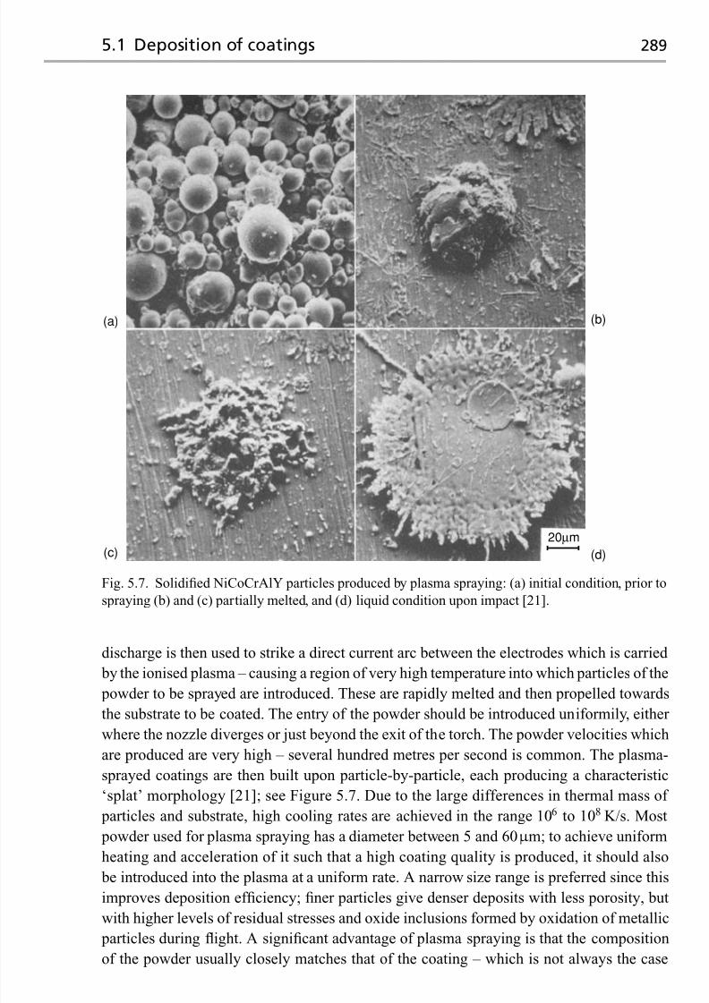
7/18/2019 The Superalloys Fundamentals and Applications
http://slidepdf.com/reader/full/the-superalloys-fundamentals-and-applications 307/389
5.1 Deposition of coatings 289
20μm
(a) (b)
(c) (d)
Fig. 5.7. Solidified NiCoCrAlY particles produced by plasma spraying: (a) initial condition, prior to
spraying (b) and (c) partially melted, and (d) liquid condition upon impact [21].
discharge is then used to strike a direct current arc between the electrodes which is carried
by the ionised plasma – causing a region of very high temperature into which particles of the
powder to be sprayed are introduced. These are rapidly melted and then propelled towards
the substrate to be coated. The entry of the powder should be introduced uniformily, either
where the nozzle diverges or just beyond the exit of the torch. The powder velocities which
are produced are very high – several hundred metres per second is common. The plasma-
sprayed coatings are then built upon particle-by-particle, each producing a characteristic
‘splat’ morphology [21]; see Figure 5.7. Due to the large differences in thermal mass of
particles and substrate, high cooling rates are achieved in the range 106 to 108 K/s. Most
powder used for plasma spraying has a diameter between 5 and 60μ m; to achieve uniform
heating and acceleration of it such that a high coating quality is produced, it should also
be introduced into the plasma at a uniform rate. A narrow size range is preferred since thisimproves deposition efficiency; finer particles give denser deposits with less porosity, but
with higher levels of residual stresses and oxide inclusions formed by oxidation of metallic
particles during flight. A significant advantage of plasma spraying is that the composition
of the powder usually closely matches that of the coating – which is not always the case

7/18/2019 The Superalloys Fundamentals and Applications
http://slidepdf.com/reader/full/the-superalloys-fundamentals-and-applications 308/389
290 Environmental degradation: the role of coatings
Bond coatSubstrate
Oxide film
Columnar zirconia Lamellar zirconia
Fig. 5.8. Comparison of the microstructure of EB-PVD and plasma-sprayed TBCs [22].
with the EB-PVD process, due to different evaporation rates of the elements in the charge.
A disadvantage of the process is that it is difficult to produce fully dense coatings without
some porosity. Figure 5.8 compares the coating microstructure of plasma-sprayed and EB-
PVD coatings, which display very different characteristics by virtue of the differing growth
modes [22].
There are many types of plasma spraying apparatus available, from the basic systems
which operate in air to the more sophisticated, fully automated systems which operate in
a controlled environment or else in vacuum. With air plasma spraying (APS), the sprayed
particles impact and deform, but perfect bonding is not achieved due to the presence of
surface oxide films that cause oxide stringers to be present; consequently, they are charac-
terised by their relatively low bond strengths and appreciable porosity. The low-pressure
plasma spraying (LPPS) or vacuum plasma spraying (VPS) process circumvents some of
these difficulties, because clean coatings are produced with virtually no oxide inclusions;
see Figure 5.9. Since the plasma jet exhausts into a enclosed chamber held between 0.04 and
0.4 atm, significant expansions of the temperature isotherms and velocity contours of the
plsama jet are achieved relative to APS; this is due to the increased mean free path between
ions and electrons in the plasma – leading to very long spray distances. For example, spray
distances for MCrAlX-type overlay coatings using the APS process are in the range 75 to
100 mm, whereas for VPS these are extended to greater than 400 mm [6]. At these so-called
stand-off distances, the plume diameters are about 10 mm for APS and 50 mm for VPS.
These characteristics lead to more uniform and consistent coatings, high densities close
to the theoretical values, low residual stresses and the attainment of increased deposition
thicknesses. Nevertheless, the use of VPS does come with some additional complications.
The enclosed environment of the chamber necessitates robotic manipulation of the spray
gun, vacuum interlocks, exhaust cooling, dust filtration and chamber-wall cooling, all of which add to the cost of the process. Consequently, the use of VPS is often used only where
absolutely necessary; for combustor applications, for example, it is common to deposit an
MCrAlX-type overlay bond coat using VPS prior to a YSZ-based thermal barrier coat-
ing using APS, to take advantage of lower cost and higher coating porosity of the latter
process.

7/18/2019 The Superalloys Fundamentals and Applications
http://slidepdf.com/reader/full/the-superalloys-fundamentals-and-applications 309/389
5.1 Deposition of coatings 291
Fig. 5.9. Commercial vacuum plasma spraying (VPS) equipment for the production of thermally
sprayed coatings. (Courtesy of Sulzer Metco.)
Recently, attentionhas been paid to techniques bywhich ‘segmentation cracks’ – running
perpendicular to the coating surface and penetrating a significant fraction of the coating
thickness – can be deliberately introduced into plasma-sprayed TBCs of YSZ [23]. The mi-
crostructure then resembles thatofa TBC producedbythe EB-PVDmethod; see Figure 5.10.
It has been demonstrated that coatings fabricated in this way have improved resistance to
spallation during thermal cycling, so that thicker TBCs can be produced which provide
greater thermal insulation. Control of the substrate interpass temperature during spraying
has been shown to be vital if segmentation cracks are to be introduced successfully – the
range 500 to 800 ◦C is appropriate, with higher temperatures producing a greater crack den-
sity. The use of solid powder (fused and crushed) feedstock rather than the hollow-sphere
(HOSP) variety is also helpful [24], although the latter gives rise to a greater porosity levels,
which promote lower thermal conductivities. Although more research is required to eluci-date the formation mechanism of segmentation cracks, it seems probable that the higher
interpass temperatures cause successive splat layers to be present in the partially molten
state, as evidenced by a common columnar solidification structure which then runs across
them; the thermal strains induced bycoolingare then able to promotesegmentation cracking
upon cooling, with improved intersplat bonding possibly playing a role. Unfortunately, the

7/18/2019 The Superalloys Fundamentals and Applications
http://slidepdf.com/reader/full/the-superalloys-fundamentals-and-applications 310/389
292 Environmental degradation: the role of coatings
Fig. 5.10. Typical coating structures produced by plasma spraying of yttria-stabilised zirconia:
(a) conventional processing conditions and (b) conditions designed to produce segmentation
cracking. (Courtesy of Hongbo Guo.)
high porosity levels required for coatings of the lowest thermal conductivity are produced
with low rather than high substrate temperatures – this indicates that, if segmentation cracks
are to be introduced into any given coating material to improve its strain tolerance, then a
greater thermal conductivity must be accepted.

7/18/2019 The Superalloys Fundamentals and Applications
http://slidepdf.com/reader/full/the-superalloys-fundamentals-and-applications 311/389
5.1 Deposition of coatings 293
5.1.3 Pack cementation and chemical vapour deposition methods
In the pack cementation process, the components to be coated are immersed in a powder
mixture within a sealed or semi-sealed retort – this is then heated in a protective atmosphere
until a coating of sufficient thickness is formed [25–28]. The pack consists of (i) the coatingelement source, (ii) an activator (such as NaF, NaCl or NH4Cl) and (iii) an inert filler
material, often alumina, which prevents the source from sintering [25]. The pack processes
include chromising and siliconising, but aluminising is probably the most important and
widely used in the gas turbine industry; for example, the vast majority of aeroengine turbine
blade aerofoils are aluminised in some way to improve their resistance to high-temperature
oxidation or as a surface preparation prior to the deposition of a TBC. In this case, the source
can be either pure aluminium or an aluminium alloy (for example, Cr–30 wt%Al) depending
upon the aluminium activity required; it is the difference between the activity of Al in the
source and the substrate surface which represents the driving force for coating deposition.
Broadly speaking, theactivator reactswith thealuminiumsource to formaluminiumhalides;
these are transported to the surface of the substrate where they are deposited, allowing them
to react with the alloy and thus release aluminium.
The flexibility arising from the choice of aluminium activity in the source allows two
distinct types of coating microstructure to be built up [4,29]. When the Al activity is high,
an external brittle layer of δ –Ni2Al3 forms at the substrate surface (see Figure 5.11); alu-
minium is then the main diffusing species and the coating grows inwards. The diffusion
coefficient of Al in δ is such that the process can then be carried out at relatively low tem- peratures, for example, 870 ◦C for 20 h – hence the term ‘low-temperature, high-activity’
(LTHA) is applied in this case. Subsequent heat treatment – for example, 1100 ◦C for 1h –
is used to promote the diffusion of Al inwards and Ni outwards such that a surface layer
of β –NiAl is formed on the γ/γ substrate, with an ‘interdiffusion zone’ (IDZ) forming
between the two (see Figure 5.12); microanalysis using energy dispersive spectroscopy con-
firms that the IDZ is rich in slow-diffusing elements such as Re, W and Ta between the
two (see Figure 5.13). Alternatively, if a low-activity pack is used then an externalβ –NiAl
layer forms immediately during aluminisation, predominantly by the outward diffusion of
nickel [4]. Since a relatively high temperature of 1100 ◦C is required in this case to promotereasonable diffusion rates, it is referred to as the ‘high-temperature, low-activity’ (HTLA)
version of the process. Often, platinum-modified aluminide coatings are produced by elec-
troplating a thin layer of Pt onto the surface of the superalloy; to encourage its adherence,
a grit-blasting treatment is often applied prior to Pt electrodeposition. The incorporation
of Pt into the aluminide layer in this way has been shown to improve the long-term oxida-
tion resistance [30,31]. Traditionally, this has been attributed [32–34] to the exclusion of
refractory elements from the outer aluminide layer caused by the presence of Pt; however,
recent work [35] has disputed this view, the beneficial effect of platinum being linked to the
minimisation of void formation at the coating/oxide interface and a retention of the oxide
scale.
One drawback of the pack-cementation process is that it can only be used effectively
to coat those blade surfaces which may be brought into direct contact with the pack, so

7/18/2019 The Superalloys Fundamentals and Applications
http://slidepdf.com/reader/full/the-superalloys-fundamentals-and-applications 312/389
294 Environmental degradation: the role of coatings
Fig. 5.11. Microstructures of the CMSX-10 single-crystal superalloy, following the
low-temperature, high-activity, pack-cementation aluminisation process of 870 ◦C for 20 h.
(Courtesy of Matthew Hook.)
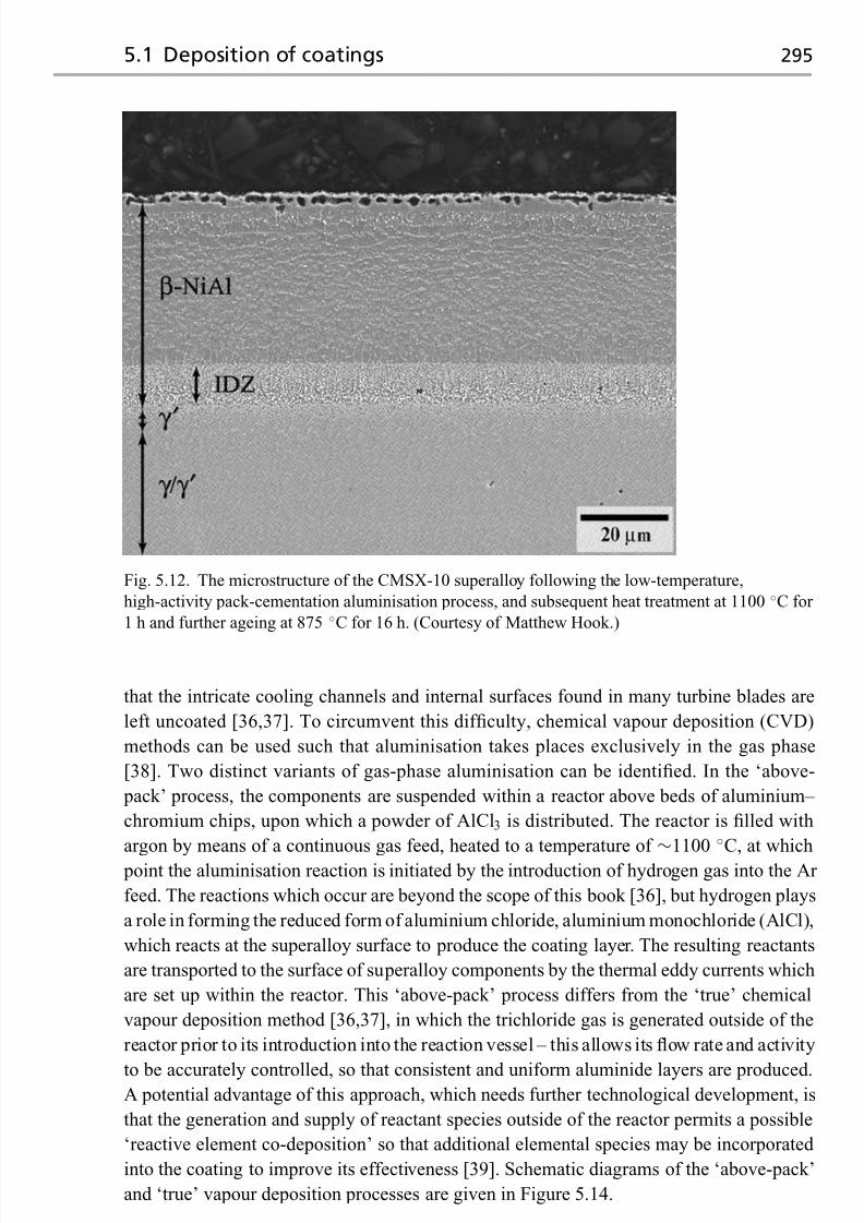
7/18/2019 The Superalloys Fundamentals and Applications
http://slidepdf.com/reader/full/the-superalloys-fundamentals-and-applications 313/389
5.1 Deposition of coatings 295
Fig. 5.12. The microstructure of the CMSX-10 superalloy following the low-temperature,
high-activity pack-cementation aluminisation process, and subsequent heat treatment at 1100 ◦C for
1 h and further ageing at 875 ◦C for 16 h. (Courtesy of Matthew Hook.)
that the intricate cooling channels and internal surfaces found in many turbine blades are
left uncoated [36,37]. To circumvent this difficulty, chemical vapour deposition (CVD)
methods can be used such that aluminisation takes places exclusively in the gas phase
[38]. Two distinct variants of gas-phase aluminisation can be identified. In the ‘above-
pack’ process, the components are suspended within a reactor above beds of aluminium–
chromium chips, upon which a powder of AlCl3 is distributed. The reactor is filled with
argon by means of a continuous gas feed, heated to a temperature of ∼1100 ◦C, at which
point the aluminisation reaction is initiated by the introduction of hydrogen gas into the Ar
feed. The reactions which occur are beyond the scope of this book [36], but hydrogen plays
a role in forming the reduced form of aluminium chloride, aluminium monochloride (AlCl),
which reacts at the superalloy surface to produce the coating layer. The resulting reactants
are transported to the surface of superalloy components by the thermal eddy currents which
are set up within the reactor. This ‘above-pack’ process differs from the ‘true’ chemical
vapour deposition method [36,37], in which the trichloride gas is generated outside of the
reactor prior to its introduction into the reaction vessel – this allows its flow rate and activity
to be accurately controlled, so that consistent and uniform aluminide layers are produced.A potential advantage of this approach, which needs further technological development, is
that the generation and supply of reactant species outside of the reactor permits a possible
‘reactive element co-deposition’ so that additional elemental species may be incorporated
into the coating to improve its effectiveness [39]. Schematic diagrams of the ‘above-pack’
and ‘true’ vapour deposition processes are given in Figure 5.14.

7/18/2019 The Superalloys Fundamentals and Applications
http://slidepdf.com/reader/full/the-superalloys-fundamentals-and-applications 314/389
296 Environmental degradation: the role of coatings
Ni
Al
Cr
Co
Ta
W
Re
Cr
Co
Ta
W
Re
δ –Ni2Al3 γ/γ ' bulk substrate
Ni
Al
90
80
70
60
50
40
30
20
10
0
A t o m i c %
A t o m i c %
0 10 20 30 40 50 60
Distance from surface (μm)
Distance from surface (μm)
(a)
(b)β –NiAl γ '
Co
Cr
TaWRe
5
4
3
2
1
020 30 40 50 60 70
Interface
Interdiffusion zone (IDZ)
Fig. 5.13. Surface concentration profiles of the CMSX-10 superalloy (a) after the LTHA
aluminisation process of 870 ◦C for 20 h, and (b) after subsequent heat treatment 1100 ◦C for 1 h
and further ageing at 875 ◦C for 16 h. (Courtesy of Matthew Hook.)

7/18/2019 The Superalloys Fundamentals and Applications
http://slidepdf.com/reader/full/the-superalloys-fundamentals-and-applications 315/389
5.2 Thermal barrier coatings 297
~1100 °C
Ar / H2 Exhaust (Ar + H2)
(a)
Superalloy component
Al / Cr metal + AlX3
~1100 °C
H2 / HX Al
−300 °C
Exhaust
(HX + H2)
(b)
Aluminium halide (AlX y) gas
Furnace element / heat source
Fig. 5.14. Schematic diagram of the two reactor types employed for CVD aluminisation. (a) The
‘above-pack’ technique relies on the in situ evolution of the aluminium halide species, whereas the
‘true’ CVD process, (b), generates the aluminide halides externally and prior to introduction into the
reactor.
5.2 Thermal barrier coatings
5.2.1 Quantification of the insulating effect
The potency of the insulation effect produced by a thermal barrier coating is best illustrated
with the following quantitative example.
Example calculation
Consider a hollow, high-pressure turbine blade operating in a gas stream at 1450 ◦C, such
that the outer and inner surfaces are at 1000 ◦C and 800 ◦C, respectively – the mean metal
temperature is then 900 ◦C. The wall thickness can be taken as 5 mm; see Figure 5.15(a).Determine the decrease in metal temperature and steady-state heat flux arising from the
addition of a 1 mm-thick thermal barrier coating (TBC); see Figure 5.15(b). The superalloy
and TBC have thermal conductivities of 100 and 1 W/(m K), respectively. Assume that
the heat transfer coefficient at the outer surface of the blade is unaltered by the addition of
the TBC.

7/18/2019 The Superalloys Fundamentals and Applications
http://slidepdf.com/reader/full/the-superalloys-fundamentals-and-applications 316/389
298 Environmental degradation: the role of coatings
Metal
Metal
Ceramic
(a)
(b)
Coolingair
Gasstream
Fig. 5.15. Temperature profiles across a cooled turbine blade aerofoil (a) without a thermal barrier
coating (TBC) and (b) with the TBC in place.
Solution Without the TBC, the temperature gradient across the superalloy is 200/5×
10−3 or 4× 10⁴ K /m. Multiplying by the thermal conductivity gives a value of the heat
flux, q, of 4× 10⁶ W/m2; this must equal the product of the temperature drop across the
gas stream/metal interface of 450 ◦C and the film transfer coefficient,h. An estimate of this
last quantity is therefore 4× 10⁶/450 or 8.9× 10³ W/(m2 K).
With the TBC added, let x and y be the new temperatures at the metal/ceramic interface
and ceramic/gas stream interfaces, respectively. The equivalence of the new heat flux,q ,
through the coated system means that
q = 100× ( x − 800)/5× 10−3 = 1× ( y − x)/1× 10−3 = 8.9× 10³(1450− y)
On solving these equations one finds that the temperature of the outer surface of the super-
alloy is now 828 ◦C, so that the mean metal temperature is reduced to 814 ◦C. The new flux,
q ,isthen5.6× 105 W/m2, i.e. 14% of the value without the TBC in place. The analysis can
be used to confirm that both the flux and mean metal temperature decrease as the thickness
of the ceramic layer is increased and its thermal conductivity is reduced.
5.2.2 The choice of ceramic material for a TBC
The above considerations confirm the usefulness of a thermal barrier coating and its de-
pendence upon the thermal conductivity of the material employed. It is well known that
ceramic compounds have low values of thermal conductivity, but which one is best for this

7/18/2019 The Superalloys Fundamentals and Applications
http://slidepdf.com/reader/full/the-superalloys-fundamentals-and-applications 317/389
5.2 Thermal barrier coatings 299
35
30
25
20
15
10
5
00 500 1000 1500 2000
Temperature (K)
T h e r m a l c o n d u c t i v i t y ( W / ( m
K ) )
Zirconia
Mg2SiO4
TiO2
ThO2
NiO
Al2O3MgO
SiC BeO
Fig. 5.16. The thermal conductivity of various polycrystalline oxides as a function of temperature
[11,40].
application? Figure 5.16 presents some data [11,40] for thermally insulating oxide materi-
als, in polycrystalline form. The thermal conductivities are in the range 1 to 30 W/(mK),
the values decreasing with increasing temperature – the reasons for this are discussed in
Section 5.2.3. Of the ceramic materials shown, zirconia (ZrO2) displays the lowest con-
ductivity, at about 2 W/(m K); moreover, no strong temperature dependence is found, so
that this material does not suffer from the drawback of a steeply increasing conductivity at
lower temperatures. These findings explain why ZrO2-based ceramics have emerged as the
materials of choice for TBC applications.
However, modern state-of-the-art TBCs are not fabricated from pure ZrO2. Instead, they
contain yttria (Y2O3) in the range 6 to 11% by weight, with a composition of 7 wt% of
yttria being very commonly used [41]. This composition was originally identified by NASA
during the 1970s as giving the best thermal cycle life in burner rig tests; see Figure 5.17 [42].
It turns out that this is the limiting composition at which the metastable ‘non-transformable’
tetragonal t phase is formed when the ceramic is quenched from the cubic phase field (see
Figure 5.18). This avoids the tetragonal to monoclinic (t→m) phase transformation, which
is associated with a 4% volume change and thus the poor thermal cycling resistance due
to cracking and spalling at low Y2O3 contents; it also reduces the thermodynamic driving
force for the dissociation at temperature into the equilibrium tetragonal t and cubic phases
which inevitably occurs over time. The tetragonal t phase is thought to be the same tetrago-
nal polymorph as the equilibrium tetragonal phase but with a very different microstructure,consisting of anti-phase domain boundaries and numerous twins [43]. When Y2O3 is com-
bined with ZrO2 in this way so that the t structure is formed, the resulting solution is known
as ‘partially stabilised zirconia’; the use of the adjective partially distinguishes it from ‘fully
stabilised zirconia’ which arises at higher Y2O3 contents when the cubic phase is stable
from ambient conditions to the melting point. For this reason, partially stabilised zirconia

7/18/2019 The Superalloys Fundamentals and Applications
http://slidepdf.com/reader/full/the-superalloys-fundamentals-and-applications 318/389
300 Environmental degradation: the role of coatings
400
300
200
100
0
C y c l e s t o f a i l u r e
4 6 8 10 12 14 16 18 20 22 24 26
Concentration of Y2O3 in ZrO2 (wt%)
Fig. 5.17. Results from burner rig tests, which confirm the optimum yttria content of partially
stabilised zirconia at about 7 wt% [42].
0
0
500
1000 T e m p e r a t u r e ( ° C )
1500
2000
2500
3000
5
Transformabletetragonal
(t)
Non-transformabletetragonal
(t′)
10 15 20
ZrO2 1/2(Y2O3)Mole %
Liquid (l)
Cubic(f)
l + f
t + f
m + f
Tetragonal
(t)
Mono-
clinic(m)
m
+
t
(6%) (11%)
Fig. 5.18. Phase diagram for ZrO2 –Y2O3, showing the phase fields corresponding to the monoclinic
(m), tetragonal (t) and cubic (f) phases, and the composition range for which the non-transformable
tetragonal t form is found [44]. Note that sintering at 1400 ◦C of a composition corresponding to t
must nonetheless lead to separation into the cubic and transformable tetragonal phases.

7/18/2019 The Superalloys Fundamentals and Applications
http://slidepdf.com/reader/full/the-superalloys-fundamentals-and-applications 319/389
5.2 Thermal barrier coatings 301
has emerged as the standard for TBC applications, being deposited in production onto com-
bustor sections since the 1970s using thermal spraying and onto turbine nozzle guide vanes
and blading since the 1980s using EB-VPD. It shows excellent thermal stability up to tem-
peratures of 1200 ◦C, but unfortunately beyond this point it suffers from two drawbacks.
First, partial reversion to the equilibrium t and cubic phases occurs with the tetragonal to
monoclinic transformation then occurring upon subsequent thermal cycling [44], the slug-
gishness of this reverse transformation being due to the need for diffusion of Y through the
zirconia. Second, extended exposure to high temperatures causes the sintering of the YSZ,
with an associated increase in the elastic modulus [45]. The combination of these effects
causes a loss of thermal cycling resistance.
Because of the importance of highly stable, low-thermal-conductivity ceramic materi-
als for TBC applications, research has been carried out on compositions distinct from the
7YSZ standard. For example, CeO2 rather than Y2O3 has been recommended (at a levelof 25 wt%) for the stabilisation of ZrO2 since no formation of the monoclinic phase was
observed at 1400 ◦C and during limited exposures to 1600 ◦C; unfortunately, the erosion
resistance is not improved by CeO2 [46]. Similarly, 90% substitution of Sc2O3 for Y2O3
in so-called scandia/yttria-stabilised zirconia has been found to have significantly better
tetragonal t phase stability at 1400 ◦C [47,48]. Alternatively, ZrO2-based ceramics can be
dispensed with entirely. For example, hafnia (HfO2) is a good candidate for an alternative
ceramic material; HfO2 –Y2O3 TBCs have been found to display thermal cycling resis-
tance comparable to 7YSZ, but at higher Y2O3 compositions of up to 27 wt% when the
crystal structure is fully cubic [49]. Furthermore, lanthanum zirconate (La2Zr 2O7), whichdisplays the pyrochlore crystal structure, a thermal conductivity of about 1.6 W/(m K) and
excellent thermal stability and thermal shock resistance, has been proposed as a TBC ma-
terial [50,51], as have other rare-earth zirconates based upon Gd and Sm [52]; interestingly,
none of these compounds contains structural vacancies, so there is some uncertainty as to
the reason for the low thermal conductivity of these materials. Finally, lanthanum hexa-
aluminate, which displays the magnetoplumbite structure, is considered by some to be a
promising competitor to partially stabilised zirconia for operation above 1300 ◦C due to
its resistance to sintering [53]. The science of these emerging ceramic materials for TBC
applications has been reviewed recently in ref. [54]; at the time of writing, these new ce-
ramics are not being used widely in service – although Pratt & Whitney claim to be using
a Gd 2Zr 2O7-based TBC for niche applications in military turbines. A significant difficulty
is that many of the new ceramic materials have inadequate resistance to erosion which
can occur due to sand ingestion and foreign object damage (FOD) accumulation. This
is one further reason why partially stabilised rather than fully stabilised zirconia is pre-
ferred; in this system, the erosion resistance falls off monotonically with increasing yttria
content.
5.2.3 Factors controlling the thermal conductivity of a ceramic coating
The choice of ceramic provides an intrinsic resistance to heat flow, but there are other fea-
tures on the scale of the microstructure which provide a further extrinsic contribution. To
appreciate this oneshould recognise that incrystallinesolids ingeneral,heat is transferredby

7/18/2019 The Superalloys Fundamentals and Applications
http://slidepdf.com/reader/full/the-superalloys-fundamentals-and-applications 320/389
302 Environmental degradation: the role of coatings
0
0.5
1
1.5
2
2.5
3
3.5
0 5 10 15 20 25
Yttria (wt%)
T h e r m a l c o n d u c t i v i t y (
W / ( m K ) )
EB-PVD TBC
APS TBC
Bulk zirconia
Fig. 5.19. The thermal conductivity of zirconia-based TBC materials as a function of yttria content
and processing method [56].
three mechanisms [11]: (i) electrons, which are expected to provide the major contribution
at very low temperatures, (ii) lattice vibrations, i.e. anharmonic phonon–phonon scattering,
which will dominate at intermediate temperatures and (iii) radiation, i.e. photons,which will
contribute strongly at very high temperatures. Ceramic materials in general are reasonable
electronic insulators; indeed, zirconia is a very good one, with oxygen ion diffusion being
responsible for electrical conductivity at elevated temperatures, so that any electronic con-
tribution can be neglected. The data in Figure 5.16 support this conclusion, since the thermal
conductivities decrease with increasing temperature, displaying in general the 1/T depen-
dence characteristic of the Umklapp phonon–phonon process [55] – there is no increase
with increasing temperature which would be expected from the electronic contribution. At
very high temperatures the curves reach plateaux, becoming independent of temperature; as
noted by Clarke [11], if not blocked, the radiative heat transport during thermal conductivity
measurement can lead to an apparent increase in κ at high temperatures – there is evidence
of this in Figure 5.16. Beyond 1250 ◦C, partially stabilised zirconia becomes significantly
transparent to thermal radiation at wavelengths between 0.3 and 2.8 μ m, with 90% of the
incident radiation lying in this range with about 10% of the heat flux through the zirconia
being due to radiation [56].
The above arguments indicate that further extrinsic reductions in thermal conductivity
can be won by introducing inhomogeneities on the scale of the crystal lattice and grain
structure. These considerations explain the significant decrease in theκ of yttria-stabilised
zirconia (YSZ)observed with increasing yttriacontent and thepotent influence ofprocessing
method used for deposition [56]; see Figure 5.19. Increasing the yttria content from 5 wt%to 20 wt% decreases the thermal conductivity by a factor of 2. However, the introduction of
microstructural features such as intersplat boundaries and columnar grains in PS and EB-
PVD coatings, respectively, has a comparable effect, with the former being more effective
because they lie perpendicular to the direction of heat flow. Thus a coating has a lower

7/18/2019 The Superalloys Fundamentals and Applications
http://slidepdf.com/reader/full/the-superalloys-fundamentals-and-applications 321/389
5.2 Thermal barrier coatings 303
0 200 400 600 800 1000 12000
1
2100 nm
50 nm
10 nm
5 nm
3
4
5
6
Temperature, T (°C)
T h e r m a l c o n d u c t i v i t y , k
( W / ( m K ) )
Intrinsic
1 μm
Fig. 5.20. Thermal conductivity of yttria-stabilised zirconia (7YSZ) as a function of temperatureand grain size [56].
κ when deposited by PS than by EB-PVD. In general, porosity has been shown to have
a profound influence on the thermal conductivity of TBCs fabricated by plasma spraying
[57]. Reducing the grain size has also been found to reduce the thermal conductivity [56]
(see Figure 5.20), although this effect is much less pronounced at elevated temperatures
where only the point defects are effective. Alternatively, dopants have been introduced to
YSZ-based ceramics to encourage phonon dispersion – rare-earth elements added in their
oxide form, for example, erbia, ytterbia, neodymia and gadolinia, have been shown to be
effective at reducing the thermal conductivity [56] (see Figure 5.21) because they act as
phonon scatterers. A further novel strategy proposed recently has been a ‘layered’ form of
TBC produced by sequential evaporation of two compositional variants of ceramic using a
single electron beam, made to jump between two different ceramic ingots. An advantage
of this approach is that the layer/layer boundaries lie perpendicular to the TBC growth
direction; see Figure 5.22. Columnar, mixed ceria–zirconia and alumina–zirconia TBCs
have been produced in this way, with layers exhibiting periodicity as small as 0.1 μ m [58].
Similar structures have been produced using a glow discharge plasma to vary the density of the coating deposited, the layering being produced in this case by oscillating the d.c. bias
applied to the substrate during the EB-PVD process, with reductions of about 40% inκ
being claimed relative to the state-of-the-art TBCs being used in service [56]. Further
microstructural modifications in the form of ‘herringbone’ structures have been produced

7/18/2019 The Superalloys Fundamentals and Applications
http://slidepdf.com/reader/full/the-superalloys-fundamentals-and-applications 322/389
304 Environmental degradation: the role of coatings
Reference0.0
0.2
0.4
0.6
0.8
1.0
T h e r m a l c o n d u c t i v i t y ( W / ( m K
) )
1.2
1.4
1.6
1.8
Erbia Ytterbia Neodymia Gadolinia
Fig. 5.21. Thermal conductivities of 250μ m-thick EB-PVD zirconia-based coatings doped with
various rare-earth additions at a level of 4 mol%; data measured at room temperature [56].
Fig. 5.22. (a) Microstructure of multilayered EB-PVD ceria-stabilised zirconia TBC, illustrating (b)
the formation of micro-columns formed from the vapour phase using the two-source jumping beam
method [58].
by manipulation of the substrate during deposition, giving symmetrical zig-zag or wavy
columns [59]; see Figure 5.23 – it has been claimed that the thermal conductivity of thecoatings produced in this way can be up to 25% lower than so-called straight-columned
TBCs produced ordinarily. Similar structures have been produced using high-velocity gas
flows to focus the vapour plume, a process which has been christened ‘directed vapour
deposition’ – conductivities of the 7YSZ coatings produced in this way were shown to be
equivalent to those produced by APS processing [60].

7/18/2019 The Superalloys Fundamentals and Applications
http://slidepdf.com/reader/full/the-superalloys-fundamentals-and-applications 323/389
5.3 Overlay coatings 305
Fig. 5.23. Thermal barrier coating produced with a ‘herringbone’ microstructure [59]. (Courtesy of
Martijn Koolloos, NLR, the Netherlands.)
5.3 Overlay coatings
Overlay coatings placed on the superalloys are generally of MCrAlX type, where M is
either nickel (Ni) or cobalt (Co) or a combination of the two, and X is a reactive element
added in minor proportions – yttrium (Y) is very commonly used. The coatings are thus
metallic in form. By their nature, the composition of the coating is independent of that of
the substrate (although some interdiffusion inevitably occurs) – hence, in principle, they
allow the desired surface properties to be attained for any given application, for example
with an optimum blend of oxidation and corrosion resistances, strength and ductility. The
first overlay coatings appeared in the late 1960s and were deposited using the emerging
EB-PVD technology. These were based upon cobalt alloyed with 20 to 40 wt%Cr, 12 to
20 wt%Al and yttrium levels around 0.5 wt% – with the composition Co–25Cr–14Al–0.5Y
being very successful [3]. Such Co-based overlay coatings are still used extensively and are
recognised for their superior hot-corrosion resistance. However, following much subsequent
research effort, a wide range of coating compositions are now available with additions such
as Si, Ta, Hf [61,62] or precious metals such as Pt, Pd, Ru or Re [63] – Table 5.1 lists the
compositions of some common overlay coatings, including some which featured in patent
applications during this early period of alloy development [8]. As of 1998, it has been
stated [64] that there were at least 40 patented variations of the original MCrAlY concept;the exact compositions are sometimes of a proprietary nature, and it should be noted that
the compositions used in practice are those which circumvent existing patents and are not
always those which display optimum properties. As an example, Figure 5.24 illustrates the
improvement in cyclic oxidation performance of plasma-sprayed NiCoCrAlY-type coatings
modified with additions of Si and Hf at optimised concentrations of 0.4 and 0.25 wt%,

7/18/2019 The Superalloys Fundamentals and Applications
http://slidepdf.com/reader/full/the-superalloys-fundamentals-and-applications 324/389
306 Environmental degradation: the role of coatings
Table 5.1. Compositions of some commonly used and prototype [8] MCrAlY overlay
coatings, in weight %
Ni Co Cr Al Y Ti Si Hf Others
NiCrAlY Bal 25 6 0.4 NiCrAlY Bal 22 10 1.0 NiCrAlY Bal 31 11 0.6 NiCrAlY Bal 35 6 0.5CoNiCrAlY 32 Bal 21 8 0.5CoCrAlY — Bal 25 14 0.5
NiCoCrAlTaY Bal 23 20 8.5 0.6 4 Ta NiCoCrAlYSi Bal 0–40 12.5–20 2–8 0–0.25 0–10 2–10 0–4 Nb
0–4 Mo0–20 Fe
0–5 Mn NiCrAlTi Bal 30–40 1–10 1–5 NiCoCrAlHf Bal 0–40 10–45 6–25 0–10
20005002500
Lightoxide spall
Mediumoxide spall
Heavyoxide spall
P r o g r e s s i v e f a i l u r e s t a g e s
Hours of 1149 °C cyclic oxidation
P S N i C
o C rA l Y
+ S i +
H f
P S N i C
o C
r A l Y
+ S
i
P S
N i C
o C
r A l Y
+ H
f
P S
N i C
o C
r A l Y
( h i g h Y )
E B N
i C o C
r A l Y
Spinelformation
Coatingpenetration
Substrateattack
1000 1500
Fig. 5.24. Progressive degradation of EB-PVD deposited (EB) and PS sprayed overlay coatings
showing synergistic benefit of silicon and hafnium additions [61].
respectively [61]. Much of this work became possible because of the development of plasma-spraying technology, since it was found that the EB-PVD process was not amenable
to the transfer of low-vapour-pressure elements (for example, Si, Ta, Hf) along with the
required Ni, Cr, Al and Y in the desired proportions. From this work emerged the nickel-
based overlay coatings which were designed with oxidation rather than corrosion resistance
in mind, such that an adherent Al2O3-based oxide scale is formed during exposure to high

7/18/2019 The Superalloys Fundamentals and Applications
http://slidepdf.com/reader/full/the-superalloys-fundamentals-and-applications 325/389
5.3 Overlay coatings 307
Wt%Cr
W t %
N i W
t % A l
10Ni
I
III
II
90
80
70
20 30Cr
10
20
30
AI
Fig. 5.25. Classification of Ni–Cr–Al alloys based on oxide and oxidation mechanism at 1000 ◦C
[67].
temperatures. Compositions such as Ni–25Cr–6Al–0.4Y and Ni–22Cr–10Al–1Y (wt%)
now find frequent use as overlay coatings, for example, for the bond coats in TBC systems.
Recently, the Siemens Company has introduced Re into their MCrAlY overlay coatings
used for industrial gas turbines, and demonstrated that the oxidation and thermomechanical
properties are much improved [63]. The microstructure of these coatings consists of a
two-phase mixture of the β –NiAl phase and the solid-solution of γ –Ni [65].
5.3.1 Oxidation behaviour of Ni-based overlay coatings
Given the emergence of the NiCrAlY-type compositions as nickel-based overlay coatings,
one should identify the physical reasons for their suitability for this application. Some
early papers of Pettit and co-workers [66,67] provide considerable insight. In a series of
careful and methodical experiments, it was confirmed that in Ni–Cr–Al ternary alloys, and
depending upon the precise mean composition, either an alumina (Al2O3) or a chromia(Cr 2O3) oxide scale can form exclusively during exposure to high temperatures, this despite
nickel being the majority component in these alloys so that nickel oxide might have been
expected under all circumstances. This effect has been christened ‘selective oxidation’.
The ternary diagram in Figure 5.25 illustrates the regions in which the different scales
were found to form – termed Group I, Group II and Group III behaviour – at 1000 ◦C,

7/18/2019 The Superalloys Fundamentals and Applications
http://slidepdf.com/reader/full/the-superalloys-fundamentals-and-applications 326/389
308 Environmental degradation: the role of coatings
Fig. 5.26. The oxide morphologies formed during the high-temperature oxidation of Ni–Cr–Al
alloys: (a) Group I, (b) Group II and (c) Group III [67].
although it should be noted that the I/III, II/III and I/II boundaries can alter with temperature,
heating rate and grain size. The features of the three different scales are illustrated in
Figure 5.26. Group I alloys, which are rich in Ni and thus have only low levels of Al and
Ti, are characterised by a continuous, external scale of NiO accompanied by a sub-scale
of Cr 2O3, Al2O3 and/or the spinel Ni(Al,Cr)2O4. Oxidation begins with the formation
of Ni(Al,Cr)2O4, which is rapidly overtaken by a brittle, outward-growing NiO scale;
Cr 2O3, and then Al2O3, are found at further increasing depths into the substrate due to
their low equilibrium partial pressures of oxygen. The oxidation of Group II alloys, which
contain high levels of Cr, causes an external scale of Cr 2O3 and internal precipitation
of Al2O3 – these alloys contain relatively high and low concentrations of chromium and
aluminium, respectively. Initially, a transient NiO/Ni(Al,Cr)2O4 mixed external scale and
Cr 2O3/Al2O3 sub-scale form as before; however, unlike Group I alloys, there is sufficient
chromium to support the flux required to form a continuous Cr 2O3 sub-scale, which, after time, replaces the NiO/Ni(Al,Cr)2O4 as the external oxide. Finally, oxidation of Group III
alloys – which possess appreciable concentrations of both chromium and aluminium –
result in the exclusive formation of a compact external Al2O3 scale; and, unlike Group I
and Group II alloys, no evidence of internal sub-scale precipitation is shown. Once again,
a NiO/Ni(Al,Cr)2O4 external scale arises first, but an internal and continuous sub-scale of

7/18/2019 The Superalloys Fundamentals and Applications
http://slidepdf.com/reader/full/the-superalloys-fundamentals-and-applications 327/389
5.3 Overlay coatings 309
S
S
S
S S
S S
NiO
NiO
NiO
NiO S SNiO
S
S
S
S
NiO
NiO
Alloy
Alloy
AlloyAlloy
Alloy
Group I
Group II Group III
AIAI Cr
AlloyAI Cr
O2
S SNiOO2
O2
S: Ni(Cr, Al )2 O4 : Cr2 O3 : Al2 O3
Fig. 5.27. Schematic illustration of the oxidation mechanisms occurring in Ni–Cr–Al alloys [67].
Al2O3 forms soon afterwards; the NiO/Ni(Al,Cr)2O4 eventually spalls away, leaving the
Al2O3 as the external scale. Thus the basis of the Pettit theory is that nuclei of all oxide
constituents arise at temperature, but that Al2O3 or Cr 2O3 can predominate because of their
greater thermodynamic stability, despite their growth kinetics being much slower than for
NiO. A schematic diagram of the oxidation processes occurring in Groups I–III is given in
Figure5.27.One very importantconclusion fromthiswork is that it is possible to form Group
III morphologies in the ternary system at aluminium concentrations as little as 5 wt% – this
is in contrast to the Ni–Al binary system, which requires aluminium concentrations in the
vicinity of 10 wt%. The ability of chromium to encourage the premature external oxidationof aluminium has been referred to as a ‘gettering effect’, but it may be more appropriate
to refer to it as a ‘third-element effect’ since it is likely that Cr is having an effect on the
Al activity. For example, Figure 5.25 indicates that 20 wt%Al is required in a binary Ni–Al
alloy for exclusive Al2O3 formation, but that this figure falls to 5 wt%Al when 5 wt%Cr is
added.

7/18/2019 The Superalloys Fundamentals and Applications
http://slidepdf.com/reader/full/the-superalloys-fundamentals-and-applications 328/389
310 Environmental degradation: the role of coatings
3
0−1
−3
−5
−7
−9
−11
−13
−15
0 100 200 300 400 500
Oxidation time (1 h cycles)
W e i g h t c h a n g e ( m g / c
m 2 )
5
NiCrAl
NiCrAl + Y
NiCrAl + Zr
(800 °C)1
Fig. 5.28. The effect of yttrium or zirconium dopants (0.5 wt%) in producing Al2O3 scale
adherence in 1100 ◦C cyclic oxidation tests of Ni–15Cr–13Al (1 h cycles) [69].
A comparison of Figure 5.25 and the compositions of common NiCrAlY-type coatings
confirms that the formation of Al2O3 is expected, and this does indeed form during high
temperatures. But why are the additions of Y made? The reason is the so-called ‘reactive
element effect’ [68] bywhich the adherence of the Al2O3 scale is improved bysmall amounts
(typically less than 1 wt%) of Y, La, Zr or Hf or other Group 3 and 4 elements, including
the lanthanide and actinide series. Yttrium is considered to be one of the most effective
of the reactive-element (RE) additions, and certainly for overlay coatings it is the most
popular; however, zirconium has a positive effect also, as has been proven by measurement
of the weight gain during thermal cycling; see Figure 5.28 [69]. It can be seen that the
adherent scale on doped Ni–Cr–Al exhibits parabolic growth and only minimal weight
gain; the undoped material, on the other hand, shows a mass loss which is very significant
and approximately linear with time, consistent with a high rate of re-oxidation after spalling.
It is generally accepted that the amount of the reactive-element dopant is critical if scale
adhesion is to be optimal; see Figure 5.29 [70–72]. Low concentrations (less than 100 ppm)
have been reported to reduce the growth stresses and scale-buckling effects arising from the
higher specific volume of the scale. Levels around 0.1 wt% appear to be optimal for scale
adhesion and low Al2O3 growth rates. However, at levels greater than about 0.5 wt%, the
growth rate increases again – this can be attributed to the copious formation of oxides of the
RE dopants, for example, from the oxidation of Ni5Y and Ni2AlZr precipitates, since the
solubility limit of the dopant is then exceeded. One should note that the level of yttrium in
the raw coating powder needs to be different from that in the deposited coating; for example,if air plasma spraying is used, the coating material needs to contain about 1 wt% yttrium to
be most effective, since yttrium is oxidised by the plasma torch [69] – although this effect
is less pronounced when vacuum plasma spraying is employed.
Thereactive-element effect (sometimes knownas therare-eartheffect) isvery wellknown
(see, for example, refs. [68] and [73]), and much research has been carried out in an attempt

7/18/2019 The Superalloys Fundamentals and Applications
http://slidepdf.com/reader/full/the-superalloys-fundamentals-and-applications 329/389
5.3 Overlay coatings 311
Additive, wt%
4
3
2
1
0 0
S p e
c i m e n w e i g h t c h a n g e ( m g / c m
2 )
T
o t a l w e i g h t c h a n g e ( m g / c m
2 )
80
60
40
20
10.01 0.1
INon-adherentslow growth
IIAdherent
slow growth
IIIAdherent,excessive
growth
Isothermal
Cyclic
Fig. 5.29. Schematic diagram of the effects of dopant level on growth rate and degree of spallation
in 100 h tests of MCrAlX alloys at 1100◦
C [70–72]. (Courtesy of Jim Smialek, NASA.)
to explain the improved adherence which is conferred. For example, mechanisms proposed
to account for the beneficial effects of the additions include (i) the formation of protective
pegs which ‘anchor’ the scale to the substrate metal alloy [68], (ii) the prevention of vacancy
coalescence at the metal/scale interface by providing alternative sites for coalescence [74],
(iii) the enhancement of scale plasticity [75] and (iv) the improvement of the cohesive
energy between metal and scale [68,76]. Most of these ideas have not been developed in
a quantitative fashion; much controversy still exists concerning the relative importance of
these mechanisms, their plausibilities and possible interaction. However, in recent years,
the most widely accepted explanation emphasises the role played by sulphur in promoting
Al2O3 spallation [77]. It has been known for some time that sulphur embrittles nickel
and its alloys due to its equilibrium segregation to grain boundaries, which is Gibbsian in
nature (see, for example, refs. [78] and [79]); its solubility inγ –Ni is strongly temperature-
dependent, decreasing from about 500 ppm by atom at 1200K to less than 10 ppm at 700 K,
with elements such as Cr and Hf reducing the sulphur solubility and also its degree of
grain-boundary segregation; see Figure 5.30. Consequently, it is not surprising that studies
using Auger spectroscopy have also confirmed that sulphur segregation is present at themetal/scale interfaces formed during oxidation [80]; however, these also confirmed a role
of yttrium in interacting with indigenous sulphur to form refractory sulphides such as YS
and Y2S3, so that the amount available to concentrate at the scale/metal interface is then
much reduced, or even eliminated [73]. These findings are supported by recent research on
the PWA1480 single-crystal superalloy, hydrogen annealed in a gettered 5%H2/Ar flowing
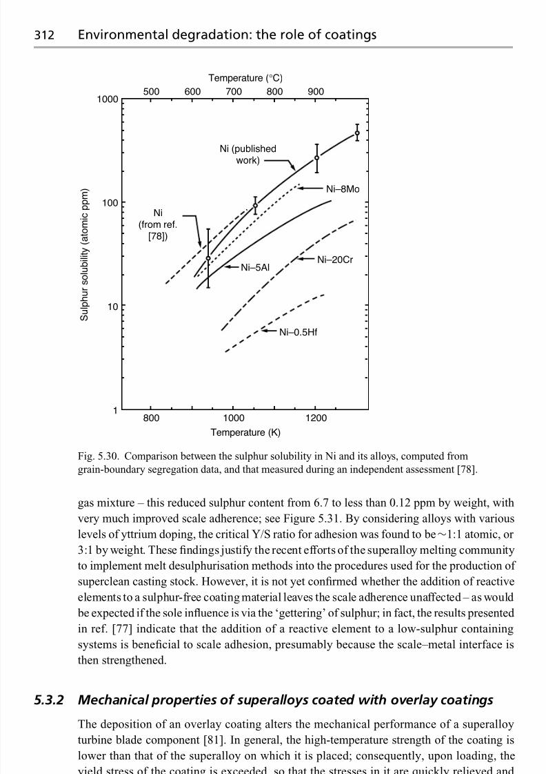
7/18/2019 The Superalloys Fundamentals and Applications
http://slidepdf.com/reader/full/the-superalloys-fundamentals-and-applications 330/389
312 Environmental degradation: the role of coatings
1000
100
10
1800 1000 1200
Temperature (K)
Temperature (°C)
S u l p h u r s o l u
b i l i t y ( a t o m i c p p m )
500 600 700
Ni (publishedwork)
800 900
Ni–8Mo
Ni–20Cr
Ni–5Al
Ni(from ref.
[78])
Ni–0.5Hf
Fig. 5.30. Comparison between the sulphur solubility in Ni and its alloys, computed from
grain-boundary segregation data, and that measured during an independent assessment [78].
gas mixture – this reduced sulphur content from 6.7 to less than 0.12 ppm by weight, with
very much improved scale adherence; see Figure 5.31. By considering alloys with various
levels of yttrium doping, the critical Y/S ratio for adhesion was found to be∼1:1 atomic, or
3:1 by weight. These findings justify the recent efforts of the superalloy melting community
to implement melt desulphurisation methods into the procedures used for the production of
superclean casting stock. However, it is not yet confirmed whether the addition of reactive
elements to a sulphur-free coating material leaves the scale adherence unaffected – as would
be expected if the sole influence is via the ‘gettering’ of sulphur; in fact, the results presented
in ref. [77] indicate that the addition of a reactive element to a low-sulphur containing
systems is beneficial to scale adhesion, presumably because the scale–metal interface is
then strengthened.
5.3.2 Mechanical properties of superalloys coated with overlay coatings
The deposition of an overlay coating alters the mechanical performance of a superalloy
turbine blade component [81]. In general, the high-temperature strength of the coating is
lower than that of the superalloy on which it is placed; consequently, upon loading, the
yield stress of the coating is exceeded, so that the stresses in it are quickly relieved and

7/18/2019 The Superalloys Fundamentals and Applications
http://slidepdf.com/reader/full/the-superalloys-fundamentals-and-applications 331/389
5.3 Overlay coatings 313
0
−5
−10
−15
W e i g h t c h a n g e ( m g / c
m 2 )
0 100 200 300
Oxidation time (1 h cycles)
400 500
6.7ppmw S
3.9
1.5
0.8
0.12
Fig. 5.31. Effect of sulphur content on the 1100 ◦C cyclic oxidation behaviour of the single-crystal
superalloy PWA1480. Note ppmw = parts per million by weight. (Courtesy of Jim Smialek.)
redistributed across the cross-section. In practice, the extent to which this is beneficial or
detrimental depends upon a number of factors – the corrosiveness of the environment, the
operating conditions which dictate the temperatures experienced, the nature of the loading
(i.e. static or cyclic) since crack nucleation may, in fact, be promoted and thedegree to which
the surface microstructure and stress state is altered. For example, during isothermal creep
conditions which are more representative of those experienced by blading in an industrial
(land-based) gas turbine, Tamarin and co-workers [1] have shown that the stress rupture
life of the JS6U superalloy at 800 ◦C and 900 ◦C is severely compromised when testing is
carried out with a gas turbine fuel (GZT) syntheticash applied to the specimens;however, the
use of a Ni–20Co–20Cr–12Al–Y overlay coating restored the properties to levels equivalent
to those of the uncoated material, even with the ash present; see Figure 5.32. Under thermal-
mechanical fatigue (TMF) loading, overlay coatings are found to perform very much better
than the aluminide coatings, which under isothermal LCF conditions have been shown to
impair the fatigue life at 600 ◦C, i.e. below the ductile-to-brittle transition temperature
(DBTT) of the aluminide coating, although the detrimental effect disappears at higher
temperatures [82].
When fatigue loading is severe – which is more representative of the aeroengine situ-
ation – property debits have been observed in isothermal laboratory tests when overlays
are employed; thus, the behaviour can be compromised by the addition of this form of
coating. Porosity inherited from plasma spraying, the increased surface roughness and the
inherent brittleness of the coating contribute to this effect. For example, during isothermallow-cycle-fatigue (LCF) testing of the VJL12U superalloy, application of a Ni–20Cr–12Al–
Y overlay coating by the EB-PVD method was found to be detrimental (see Figure 5.33),
with the reduction in life being more pronounced when testing was carried out at 20 ◦C
rather than 800 ◦C [1]. To explain this kind of observation, it has been noted that the
overlay coatings are prone to cracking below a DBTT – the magnitude of which is depen-
dent upon the coating composition. Traditionally, a recognition of the importance of the

7/18/2019 The Superalloys Fundamentals and Applications
http://slidepdf.com/reader/full/the-superalloys-fundamentals-and-applications 332/389
314 Environmental degradation: the role of coatings
700
S t r e s s ,
σ ( M
P a )
600
500
400
300
200
10010 20 40 60 100 200 1000 2000
Time to rupture (h)
800°C
900°C
No coating, in air
No coating, in ash
Coating Al–5Si–1.5Y, in ash
Coating Ni–20Co–20Cr–12Al–Yr in ash
2
2
1
1
Fig. 5.32. Creep rupture curves for the JS6U superalloy, tested in the coated and uncoated
conditions and with and without the application of a coating of synthetic ash [1].
2.01.81.6
1.4
1.2
1.0
(1)
(2)
(3)0.9
0.8
0.7
0.6
Number of cycles, N
S t r a i n
, ε
( % )
101 102 103 104
Fig. 5.33. Low-cycle-fatigue (LCF) test results [1] for the VJL12U superalloy tested at 20 ◦C, in the
uncoated condition (1), with an aluminised coating (2) and with a Ni–20Cr–12Al–Y overlay coating
(3).
DBTT in controlling cracking tendency has been used with success where in-service fatigue
problems are identified – for example, the replacement of an aluminide diffusion coating
on the blading of Rolls-Royce’s Pegasus engine (used on the Harrier, which pioneered
the vertical take-off/landing (VTOL) capability), where a CoCrAlY overlay eliminated the
problem of cracking, but only after the Al content had been reduced to 7.5 wt% to reduce

7/18/2019 The Superalloys Fundamentals and Applications
http://slidepdf.com/reader/full/the-superalloys-fundamentals-and-applications 333/389
5.3 Overlay coatings 315
30
20
10
100 200 300 400 500
Co–18Cr–9Al–Y
Co–18Cr–11Al–YCo–20Cr–12.5Al–Y
Diffusedaluminide
Temperature (°C)
600 700 800 900
S t r a i n t o c r a c
k ( % )
Fig. 5.34. Strain to cracking as a function of temperature for a number of CoCrAlY overlay
coatings, illustrating the strong composition-dependence of the ductile-to-brittle transformation
temperature [83].
(3)
(4)
1000
100 1000 10000
Number of cycles, N
S t r e s s r a n g e ( M
P a )
100000100
(1)(2)
Fig. 5.35. Thermal mechanical fatigue (TMF) results (load control, out-of-phase temperature and
loading cycles) showing the cyclic life of the CMSX-4 superalloy in the uncoated condition (4) and
with Ni–7Co–12Cr–17Al–Y (3), Ni–8Co–12Cr–7Al–Y (2) and Co–32Ni–21Cr–8Al–Y (LCO-22)
(1) overlay-type coatings [1,84].
the DBTT by several hundred degrees; see Figure 5.34 [83]. During testing under thermalcycling conditions, the effect of an overlay coating is mixed. Tamarin and co-workers [1,84]
have reported that when CMSX-4 is coated with overlay coatings and tested in a load-
controlled thermal-mechanical fatigue (TMF) rig, the coating reduces specimen life very
considerably, with cobalt-based overlays being more detrimental than nickel-based ones,
consistent with their greater brittleness; see Figure 5.35. On the other hand, Wood et al . [85]

7/18/2019 The Superalloys Fundamentals and Applications
http://slidepdf.com/reader/full/the-superalloys-fundamentals-and-applications 334/389
316 Environmental degradation: the role of coatings
Fig. 5.36. Cross-section of CoNiCrAlY overlay coating on IN738LC substrate after TMF testing,
showing extensive evidence of cracking [85].
have tested a CoNiCrAlY-type coating on conventionally cast IN738LC in strain-controlled
TMF, with cycling carried out between 300 ◦C and 900 ◦C with a two-minute dwell period
after heating and cooling. Extensive cracking of the coating was observed prior to failure
(see Figure 5.36); however, the fatigue lives of coated and uncoated specimens were not
substantially different.
When a thermal barrier coating (TBC) is employed, the resistance to thermal cycling
(for example, in a burner rig test) is dependent upon the composition of the overlay coating
onto which it is placed; see Figure 5.37 [86]. The TBC life has been found to correlatestrongly with the resistance to oxidation displayed by the overlay, which is now acting as
a bond coat [87,88]. For instance, during thermal cycling tests of TBCs fabricated from
ZrO2 –6.1 wt%Y2O3 and NiCrAlY overlay coatings of various compositions which were
placed on the Mar-M200+Hf superalloy, the spallation life is found to correlate strongly
with the specific weight gain due to oxidation; see Figure 5.38. TBC spallation life is lowest

7/18/2019 The Superalloys Fundamentals and Applications
http://slidepdf.com/reader/full/the-superalloys-fundamentals-and-applications 335/389
5.4 Diffusion coatings 317
2000
1500
1000
500
0
Bond coat composition
Ni–16Cr–6Al–Y
Ni–18Cr–12Al–Y
Ni–35Cr–6Al–Y
C y c l e s
Fig. 5.37. Results from burner rig thermal cycle tests showing lives of TBCs using three different
compositions of NiCrAlY bond coat, placed on Waspaloy substrates, with ZrO2 –7 wt%Y2O3 top
coat [86].
when the rate of oxidation is greatest, and vice versa. These effects are discussed further in
Section 5.5.
5.4 Diffusion coatings
Aluminide coatings areprone to microstructural degradationduring service. Broadly speak-
ing, two distinct modes arise. The first involves interdiffusion of the aluminide coating
– which is initially rich in the β –NiAl phase – with the superalloy substrate causing
concentration gradients set up by the coating deposition to become less pronounced. In
particular, the aluminium concentration becomes reduced over time such that theγ phase
ispromotedat the expense of β, which itselfbecomes increasinglysusceptible to transforma-
tion to the martensitic formβ via thereactionβ → β as its stoichiometry is lost [89]. Due to
these interdiffusional fluxes, Kirkendall voiding can also be found in some coating/substrate
combinations [90]. Particularly for the third-generation single-crystal superalloys which are
rich in Re, interdiffusion promotes the formation of a ‘secondary reaction zone’ (SRZ) be-
neath the interdiffusion zone (IDZ) [91,92]; see Figure 5.39. This occurs by a discontinuous
phase transformation, in which aγ matrix forms containing needles of theγ and the topo-logically close-packed phase P; thus, SRZ formation causes recrystallisation of the γ/γ
structure, but it has been demonstrated that there is no significant texture induced [92]. It
is interesting to note that a single-crystal superalloy can be prone to the SRZ effect even
though TCP precipitation does notoccur within the bulk, even after extended periods of time
at temperature – an anomaly which occurs, for example, with the MC-NG superalloy [92].

7/18/2019 The Superalloys Fundamentals and Applications
http://slidepdf.com/reader/full/the-superalloys-fundamentals-and-applications 336/389
318 Environmental degradation: the role of coatings
16
14
12
10
8
6
4
22 200 400 600 800
(a)
Cycles to failure
S
p e c i f i c w e i g h t g a i n ( m g / c m
2 )
Ni—35.0Cr—5.9Al—0.95YNi—35.4Cr—11.1Al—0.74YNi—35.7Cr—18.5Al—0.80Y
1000 1200 1400
12
10
8
6
4
22 200 400 600 800
(b)
Cycles to failure
S p e c i f i c w e i g h t g a i n ( m g / c m
2 )
Ni—35.0Cr—5.9Al—0.95YNi—35.4Cr—6.2Al—0.14YNi—35.4Cr—6.2Al—0.22YNi—35.4Cr—6.2Al—1.35Y
1000 1200 1400
Fig. 5.38. Effect of bond coat concentration on the oxidation behaviour and TBC life of
Ni–Cr–Al–Y/ZrO2 –6.1 wt%Y2O3 system for cyclic testing to a maximum temperature of 1100 ◦C:
(a) aluminium concentration and (b) yttrium concentration [87,88].
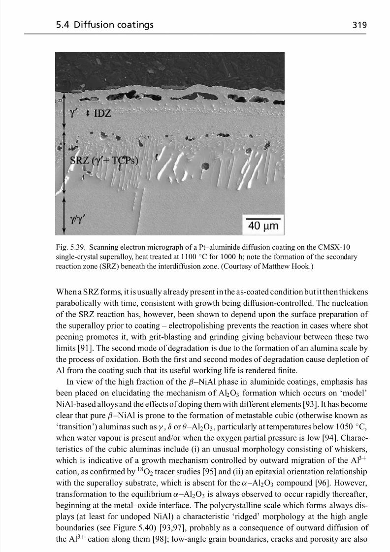
7/18/2019 The Superalloys Fundamentals and Applications
http://slidepdf.com/reader/full/the-superalloys-fundamentals-and-applications 337/389
5.4 Diffusion coatings 319
Fig. 5.39. Scanning electron micrograph of a Pt–aluminide diffusion coating on the CMSX-10
single-crystal superalloy, heat treated at 1100 ◦C for 1000 h; note the formation of the secondary
reaction zone (SRZ) beneath the interdiffusion zone. (Courtesy of Matthew Hook.)
Whena SRZ forms, it isusually already present in the as-coated condition butit then thickens
parabolically with time, consistent with growth being diffusion-controlled. The nucleation
of the SRZ reaction has, however, been shown to depend upon the surface preparation of
the superalloy prior to coating – electropolishing prevents the reaction in cases where shot
peening promotes it, with grit-blasting and grinding giving behaviour between these two
limits [91]. The second mode of degradation is due to the formation of an alumina scale by
the process of oxidation. Both the first and second modes of degradation cause depletion of
Al from the coating such that its useful working life is rendered finite.
In view of the high fraction of the β –NiAl phase in aluminide coatings, emphasis has
been placed on elucidating the mechanism of Al2O3 formation which occurs on ‘model’
NiAl-based alloys and the effects of doping them with different elements [93]. It has become
clear that pure β –NiAl is prone to the formation of metastable cubic (otherwise known as
‘transition’) aluminas such asγ , δ or θ –Al2O3, particularly at temperatures below 1050 ◦C,
when water vapour is present and/or when the oxygen partial pressure is low [94]. Charac-
teristics of the cubic aluminas include (i) an unusual morphology consisting of whiskers,
which is indicative of a growth mechanism controlled by outward migration of the Al3+
cation, as confirmed by 18O2 tracer studies [95] and (ii) an epitaxial orientation relationship
with the superalloy substrate, which is absent for the α –Al2O3 compound [96]. However,transformation to the equilibrium α –Al2O3 is always observed to occur rapidly thereafter,
beginning at the metal–oxide interface. The polycrystalline scale which forms always dis-
plays (at least for undoped NiAl) a characteristic ‘ridged’ morphology at the high angle
boundaries (see Figure 5.40) [93,97], probably as a consequence of outward diffusion of
the Al3+ cation along them [98]; low-angle grain boundaries, cracks and porosity are also

7/18/2019 The Superalloys Fundamentals and Applications
http://slidepdf.com/reader/full/the-superalloys-fundamentals-and-applications 338/389
320 Environmental degradation: the role of coatings
Zr-richprecipitates
Outer oxideridge Radial
transformationcrack
Spoke-likeridges
Inner oxide ridge,
crack healed bypolycrystallineα –Al203
Sub-grainboundaries
High-angleboundary
Porosity
Fig. 5.40. Schematic illustration of the ridged morphology of α –Al2O3 formed on β –NiAl, the
ridges forming due to the growth occurring from distinct nucleation events [97].
Fig. 5.41. Scanning electron micrograph images of the surface of a CVD (Ni,Pt)Al coating oxidised
at 1150 ◦C for 200 h. Note that no scale spallation is observed, but thin plates of alumina had
apparently flaked off some parts of the surface, leaving the underlying scale intact [99].
present, see Figure 5.41 [99]. In their analysis of Zr-doped NiAl, which was oxidised first
in 16O2 then 18O2 at 1200 ◦C, Prescott et al. [100] measured secondary ion mass spec-
trometry (SIMS) depth profiles on untransformed θ –Al2O3 and transformed α –Al2O3 (see
Figure 5.42), and demonstrated that (i) one has 18O and 16O enrichment, respectively, in
these two cases, (ii) a 18O signal, which is greater than that for 16O at depth, and (iii) a Zr

7/18/2019 The Superalloys Fundamentals and Applications
http://slidepdf.com/reader/full/the-superalloys-fundamentals-and-applications 339/389
5.4 Diffusion coatings 321
AlO(16)
AlO(18)Ni
ZrO
0100
101
102
103
104
5 10 15 20
Time (min)
(a)
(b)
C o u n t s / s
AlO(16)
AlO(18)
Ni
ZrO
0100
101
102
103
104
5 10 15 20
Time (min)
C o u n t s / s
Fig. 5.42. Secondary ion mass spectrometry (SIMS) depth profiles obtained from Zr-doped NiAl
oxidised for 12 min at 1200 ◦C [100]: (a) from untransformed, metastable θ –Al2O3 and (b) from
transformed, stable α –Al2O3.
signal, which is greatest at the oxide/scale interface in the two cases. These observations
imply that during growth of α –Al2O3 there is a strong component of O2− anion transport
inwards; taken with the observation of the ridged morphology, it seems likely that growth
occurs by mixed Al3+ cation and O2− anion grain-boundary transport. However, doping
with reactive elements (REs) such as Y, Hf, La and Zr has some significant effects. There
is a tendency for thick oxide scales to exhibit a columnar morphology, although the ef-
fects of the REs are less pronounced when scale formation occurs at higher temperatures
[94]. It has been postulated in a ‘dynamic segregation theory’ that the REs, which havea strong tendency to segregate to the grain boundaries inα –Al2O3, suppress the outward
diffusion of Al3+ [73]; while there is, as yet, no direct evidence to confirm this, it seems
plausible on account of the significant affinity of the REs for oxygen, which should promote
their migration outwards along the grain boundaries such that rare-earth oxides are formed
at the scale/gas interface – for which there is considerable evidence [73]. The dominant

7/18/2019 The Superalloys Fundamentals and Applications
http://slidepdf.com/reader/full/the-superalloys-fundamentals-and-applications 340/389
322 Environmental degradation: the role of coatings
28
26
24
22
18
14
12
10
8
6
4
2
0
16
20
24.8 29.8 32.6 34.4 37.2 40.1
Al content (at%)
T o t a l m a s s g a i n ( m g / c
m 2 )
41.9 45.2 47.8 48.3 50.2
Total mass gain
Spalled oxide
NiAl2O4
formation
Fig. 5.43. Total mass gain of specimen/spall and specific spalled oxide for various Ni–Al alloys
(+0.05 at% Hf) after ten 100 h cycles at 1200 ◦C [105].
scale-spallation mechanism of Al2O3 from NiAl is the formation of interfacial voids, which
presumably form by the Kirkendall effect; it has been widely reported that RE additions
suppress such void formation [101–103].
With regard to the effects of differences in composition of β –NiAl, the results of a
systematic series of studies [104,105] can be summarised as follows. The oxidation perfor-
mance of β –NiAl is not strongly sensitive to changes in stoichiometry induced by differing
Al/Ni ratios; however, once the Al concentration drops below∼40 at% such that a sub-
stantial amount of Ni3Al is present, then spallation occurs more rapidly; see Figure 5.43.
Hafnium-doped NiAl has been found to form an extremely slow-growing, adherent scale
[105]; in fact, when doped with 0.05 at%Hf, NiAl has been found to be the most oxidation
resistant substrate in a wide-ranging comparison of all types of α –Al2O
3formers and RE
dopants [94]. Zirconium is also best suited at a dopant concentration of 0.05 at%, but Y is
required at higher levels of 0.1 at% and La at lower levels of a few 100 ppm; there is some
indication of a synergistic effect by which co-doping of two or more REs allows the total
content to be reduced [106]. The solubility of the RE in the coating is considered to be an
important issue, which explains why La and Y work less well than Zr inβ –NiAl diffusion
coatings, but adequately in the MCrAlY overlay coatings. The Pt effect has been studied,
but no strong evidence has been found to support the widely held view that it acts as a
diffusion barrier, or that it reduces substantially theα –Al2O3 scale growth rate [12,107].
Moreover, it appears that Pt does not act as a RE; 100 times more Pt than Hf is required toimprove the scale adherence of near-stoichiometric NiAl (see Figure 5.44), and the scale
morphology is not altered substantially. However, recent studies of the oxidation behaviour
of ternary Ni–Al–Pt alloys have been revealing [105] – for pure Ni–Al unalloyed with Pt,
the concentration below which a Ni-rich rather than anα –Al2O3 scale was found to form
during 500 h cyclic oxidation between ambient and 1000 ◦C was found to lie between 40.0
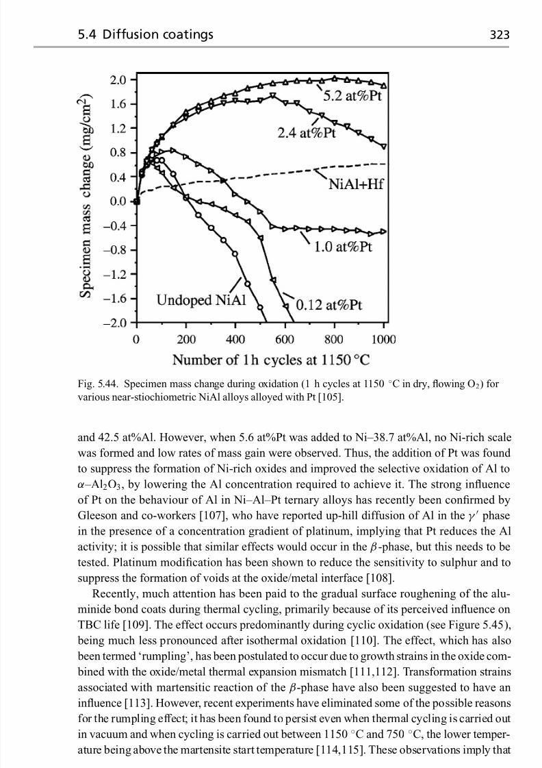
7/18/2019 The Superalloys Fundamentals and Applications
http://slidepdf.com/reader/full/the-superalloys-fundamentals-and-applications 341/389
5.4 Diffusion coatings 323
Fig. 5.44. Specimen mass change during oxidation (1 h cycles at 1150 ◦C in dry, flowing O2) for
various near-stiochiometric NiAl alloys alloyed with Pt [105].
and 42.5 at%Al. However, when 5.6 at%Pt was added to Ni–38.7 at%Al, no Ni-rich scale
was formed and low rates of mass gain were observed. Thus, the addition of Pt was found
to suppress the formation of Ni-rich oxides and improved the selective oxidation of Al to
α –Al2O3, by lowering the Al concentration required to achieve it. The strong influence
of Pt on the behaviour of Al in Ni–Al–Pt ternary alloys has recently been confirmed by
Gleeson and co-workers [107], who have reported up-hill diffusion of Al in theγ phase
in the presence of a concentration gradient of platinum, implying that Pt reduces the Al
activity; it is possible that similar effects would occur in the β-phase, but this needs to be
tested. Platinum modification has been shown to reduce the sensitivity to sulphur and to
suppress the formation of voids at the oxide/metal interface [108].
Recently, much attention has been paid to the gradual surface roughening of the alu-
minide bond coats during thermal cycling, primarily because of its perceived influence on
TBC life [109]. The effect occurs predominantly during cyclic oxidation (see Figure 5.45),
being much less pronounced after isothermal oxidation [110]. The effect, which has also
been termed ‘rumpling’, has been postulated to occur due to growth strains in the oxide com-
bined with the oxide/metal thermal expansion mismatch [111,112]. Transformation strainsassociated with martensitic reaction of the β-phase have also been suggested to have an
influence [113]. However, recent experiments have eliminated some of the possible reasons
for the rumpling effect; it has been found to persist even when thermal cycling is carried out
in vacuum and when cycling is carried out between 1150 ◦C and 750 ◦C, the lower temper-
ature being above the martensite start temperature [114,115]. These observations imply that

7/18/2019 The Superalloys Fundamentals and Applications
http://slidepdf.com/reader/full/the-superalloys-fundamentals-and-applications 342/389
324 Environmental degradation: the role of coatings
(a) (b) (c) (d)
As deposited Cyclicoxidation
Isothermal oxidation
Fig. 5.45. Optical micrographs (plan view) of superalloy coupons with low-activity Pt-modified
CVD aluminide coating and 7 wt%YSZ TBC deposited by EB-PVD, subjected to cyclic oxidation
(dwell time of 1 h at 1150◦
C) and viewed under oblique illumination to reveal the topology of thethermally grown oxide (TGO): (a) before oxidation, (b) after 250 cycles, (c) after 450 cycles and
(d) after isothermal oxidation for 500 h at 1150 ◦C [110].
neither the martensitic reaction northegrowth of thealumina scale are required for rumpling
to be observed, although it is conceivable that they contribute to the effect. Furthermore, no
rumpling is observed on the surface of bulk (Ni,Pt)Al alloys chosen to have compositions
similar to that of a typical Pt–Al bond coat [114,115]. Given these circumstances, it seems
likely that interactions between the bond coat and the superalloy substrate are responsible
for the rumpling effect. Moreover, since rumpling occurs with a characteristic wavelength
close to the β-grain size of the aluminide coating [116,117], theβ → γ transformation is
implicated since γ precipitation occurs preferentially on theβ-grain boundaries contained
within the coating.
5.5 Failure mechanisms in thermal barrier coating systems
5.5.1 Introduction
A thermal barrier coating (TBC) system is prone to failure under the action of thermal
cycling between ambient temperature (as at engine start-up) and the working conditions
experienced during service. Most usually, this manifests itself as delamination at (or near
to) the interface between the bond coat and the ceramic top coat; see Figure 5.46 [118].
It occurs during cooling, or very soon after ambient conditions are attained; however, it
is rare for the coating to fail completely – some pieces of it remain intact, and significant
scatter is observed in the time to failure if testing is repeated under identical conditions. The
driving force for delamination arises from the temperature gradients set up during thermalcycling coupled with the differing thermal expansion coefficients of the various constituents
present (for example, superalloy substrate, bond coat, ceramic top coat), but, as will be seen,
various degradation mechanisms arise [14,119]; some or all of these must operate before
failure finally occurs. It is emphasised that, at this point, controversy exists concerning the
circumstances leading to TBC failure – possibly due to the difficulty in reproducing the

7/18/2019 The Superalloys Fundamentals and Applications
http://slidepdf.com/reader/full/the-superalloys-fundamentals-and-applications 343/389
5.5 Failure mechanisms in TBC systems 325
Fig. 5.46. Failure of an EB-PVD YSZ/NiCoCrAlY thermal barrier coating on a service-exposed
high-pressure vane of a commercial civil aeroengine [118].
failure conditions (for example, temperature gradients, cycling times) pertinent to the gas
turbine in the laboratory; although much research is still being carried out on this topic,
some common characteristics have been identified. It has also become clear that TBC life
is very dependent upon the combination of materials (substrate, bond coat, ceramic) and
processes (EB-PVD, plasma spraying) used. The possibility of TBC failure represents a
major threat to the integrity of a turbine engine – consequently, much attention is being paid
to the factors which exacerbate it. From an engineering standpoint, a predictive capability
is required so that full advantage can be taken of the extra temperature capability warranted
by the presence of the TBC; this will allow them to be used in ‘prime-reliant’ rather than
‘band-aid’ mode. However, at the time of writing, this has not yet been achieved – there is a
need to identify and quantify the chemical and mechanical factors which are the precursors
to failure.
5.5.2 Observations of failure mechanisms in TBC systems
It is helpful to summarise the various observations which have been made concerning the
microstructural degradation effects and failure mechanisms occurring in TBC systems.
They are as follows.

7/18/2019 The Superalloys Fundamentals and Applications
http://slidepdf.com/reader/full/the-superalloys-fundamentals-and-applications 344/389
326 Environmental degradation: the role of coatings
(a)
(b)
(c)
TBC layer
Oxide film
Bond coat
Substrate
Crack nucleation
50 μm
50 μm
50 μm
Crack extension
Fig. 5.47. Microstructural and morphological evolution at various stages of coating life in a
Pt-modified aluminide/EB-PVD YSZ thermal barrier coating [120]. (a) After 20 cycles,
corresponding to 8% of cyclic life; (b) 80 cycles, corresponding to 34% of life; (c) 180 cycles,
corresponding to 76% of life. Note that imperfections and cracks are present after only 34% of
cyclic life.
(1) Since the ceramic top coat is unable to prevent ingress of oxygen, a ‘thermally grown
oxide’ (TGO) forms during thermal cycling due to oxidation at its interface with the
underlying bond coat; see Figure 5.47 [120]. The thickness of the TGO layer increases
parabolically with time (see Figure 5.48) [121]; this is strong evidence that its formation
is diffusion-controlled. A TGO is already present after deposition of the ceramic; by

7/18/2019 The Superalloys Fundamentals and Applications
http://slidepdf.com/reader/full/the-superalloys-fundamentals-and-applications 345/389
5.5 Failure mechanisms in TBC systems 327
0
0
1
2
3
4
5
6
7
8
9
10
500 1000 1500 2000 2500Cycles
T G O
t h i c k n e s s ( μ m
)
IN100
Parabolic
Rene 142
PAWA1483
CMSX-4
IN617/1050 °C
MAR M002
Fig. 5.48. Growth kinetics of thermally grown oxide (TGO) in a number of EB-PVD
NiCoCrAlY/YSZ TBC systems [121].
the time that the thickness reaches 10μ m, TBC failure has usually occurred [122].
Thus there is a correlation between the thickness of the TGO and the TBC life which
has been consumed.
(2) The bond coat becomes deleted of aluminium over time; this is due to (i) formation
of the TGO, which has been shown to be predominantly α-alumina [123] and (ii)
interdiffusionwith thesubstrate,whichcauses theβ-phase todissolve and theformation
of γ to be promoted [12,124]. Interdiffusion with the substrate provides an opportunity
for elements not present in the coating to reach the bond coat/TGO interface, and to
influence TBC life [121].
(3) Due to the thermal stresses arising from a mismatch in thermal expansion coefficients
and growth stresses due to the mechanism of its formation, the TGO layer forms
with a significant biaxial in-plane compressive stress in it; photo-luminescence studies
indicate that these can approach 4 GPa, with the strain increasing with thickness [125].
The action of thermal cycling reduces the average compressive stress measured in the
TGO; see Figure 5.49 [110].
(4) As TBC life is consumed during cycling, imperfections at or near the TGO (due
to processing-related variations in thickness, the mechanism of formation of theα-
alumina, the formation of γ and/or further chemical reactions which produce further
phases such as spinels and garnets) become amplified [120,126,127]. Particularly for
TBCs processed by EB-PVD, the TGO is initially smooth but develops undulations
over time as it thickens [120]; see Figure 5.47. However, when PS is used, the TGOinherits considerable roughness from the processing step and does not roughen further
to any appreciable extent before failure; see Figure 5.50 [128].
(5) Incipient cracks in the form of separations nucleate at the imperfections – these grow
and coalesce to reduce the elastic strain energy in the system [129]. Final failure occurs
once the cracks have grown to a size to support buckle propagation (see Figure 5.51),

7/18/2019 The Superalloys Fundamentals and Applications
http://slidepdf.com/reader/full/the-superalloys-fundamentals-and-applications 346/389
328 Environmental degradation: the role of coatings
0 100 200 300 400 5000
5
10
15
20
25
0.0
1.0
2.0
3.0
4.0
Time at 1150 °C (h)
F r e q u e n c y s h i f t ( 1 / c m )
E q u i v a l e n t b i a x i a l c o m p r e s s i o n
( G P a )
(4)
(3)
(1)
(2)
(5)
(6)
Fig. 5.49. Frequency shift of Cr 3+ luminescence and equivalent biaxial compression in Al2O3 scales
during cyclic oxidation at 1150 ◦C (1 h cycles) [110]. (1) Average stress underneath 60 μ m TBC;
local stress values for the (2) visually intact and (3) separated regions on the same sample; (4) stress
in fractured or spalled fragments of the TGO; (5) average stress on similar samples without the
TBC; and (b) with 130 μ m TBC and fully intact TBC–TGO interface.
usually uponcoolingwhen theceramic layer gets placed in compression [130];however,
delaminations of the TBC in the form of incipient buckles are present before final
failure, implying that they can grow in a stable fashion [131].
(6) The lifetimes of different combinations of substrate, bond coat and top coat vary con-
siderably [121]; the processing method used for the deposition of the ceramic top coat
(for example, EB-PVD, plasma spraying) is also found to be influential. TBCs with ce-
ramic top coats produced by EB-PVD are generally found to perform better than those
produced by plasma spraying (see Figure 5.52) [132], on account of their superior
‘strain tolerance’ arising from the microcracks inherited from the coating process. The
best method for producing the bond coat (for example, aluminide by CVD, MCrAlY
by EB-PVD or an alternative) is not yet apparent.
(7) Various other complicating factors can arise during engine operation. For example,
TBCs can be subject to ‘foreign object damage’ (FOD) arising from the impact of
airborne matter ingested by the engine [133]. Alternatively, calcia, magnesia, alu-
mina and silica (CMAS) can deposit upon the surface of the TBC, causing partialdissolution of the TBC and exacerbating failure [134] since its strain tolerance is re-
duced and the stiffness increased. Vanadium impurities are found in kerosene, and
these can leach Y out of the YSZ coating over time. Differences in substrate geom-
etry, changes in its local radius of curvature and the testing method influence TBC
life [135].

7/18/2019 The Superalloys Fundamentals and Applications
http://slidepdf.com/reader/full/the-superalloys-fundamentals-and-applications 347/389
5.5 Failure mechanisms in TBC systems 329
Fig. 5.50. Evolution of the ceramic/bond coat interface in an APS-sprayed YSZ/LPPS-sprayed
CoNiCrAlY system: (a) as-deposited, (b) after exposure for 216 h at 1010 ◦C, showing the
formation of a 3-μ m-thick TGO and (c) after exposure for 1944 h at 1010 ◦C, showing the presence
of cracks penetrating the TGO next to imperfections in the coating [128].

7/18/2019 The Superalloys Fundamentals and Applications
http://slidepdf.com/reader/full/the-superalloys-fundamentals-and-applications 348/389
330 Environmental degradation: the role of coatings
Fig. 5.51. Microstructure of a Pt-modified aluminide/EB-PVD YSZ thermal barrier coating system
after 450 × 1 h cycles to 1150 ◦C showing separation of the ceramic/TGO interface and the onset of
small-scale buckling [110].
(#) Number of samples
–Maximum –Average –Minimum
(10)
2500
2000
1500
1000 C y c l e s t o f a i l u r e
500
0I
Pt-Al
EB-PVD Plasma-sprayed
MCrAlY-I MCrAlY-II MCrAlY-I
III V IV II
(3)
Coating type
Bond coat
Ceramic process
(4)
(2)(2)
Fig. 5.52. Spallation lives of five production TBC systems tested in a cyclic furnace-controlled
thermal rig, from ambient to 1121 ◦C with 1 h cycles: (I) Rene N5/Pt–Al/EB-PVD YSZ;
(II) IN939/MCrAlY/PS YSZ; (III) CMSX-4/MCrAlY/EB-PVD YSZ (IV) CMSX-4/MCrAlY/PS
YSZ and (V) MarM509/MCrAlY/PS YSZ [132].

7/18/2019 The Superalloys Fundamentals and Applications
http://slidepdf.com/reader/full/the-superalloys-fundamentals-and-applications 349/389
5.5 Failure mechanisms in TBC systems 331
Fig. 5.53. Delamination modes for compressed films: (a) edge delamination and (b) buckling
delamination for the straight-sided blister [137].
5.5.3 Lifetime estimation models
Existing methods for estimating the number of cycles before a TBC spalls away from thesurface ofa superalloy arehighlyempirical; forexample,use ismade ofcylindrical testpieces
exposed to burner rigs or else experienced gained from full-scale engine ‘type’ tests. Early
work [136] made use of the notion of a ‘critical thickness’ of the TGO for TBC failure,
termed δc, for TBC failure, which was then incorporated into a modified version of Miner’s
law – such that the ratio δ/δc (where δ is the sub-critical TGO thickness) is then a quantity
that can be related (by a suitable functional form) to the life consumed. Unfortunately, this
kind of approach is not fundamentally based upon the principles of fracture mechanics; for
example, the driving force for interfacial crack growth and the interfacial toughness remain
unaccounted for. Clearly, there is a need for physically based laws which model the failure
mechanisms occurring and which, ideally, account for the microstructural effects causing
the substantially different behaviour of varying combinations of substrate, bond coat and
ceramic types.
Whilst much work remains to be done, progress in this regard has been made by Evans
and co-workers (for example, see ref. [129]), who have produced ‘failure maps’ via the
mathematical analysis of the micromechanics of TBC systems. Emphasis is placed on the
competition (see Figure 5.53) between (i) delamination from edges, such as the trailing edge
of the turbine blade, which is resisted by the mode II interfacial fracture toughness,II
,
and (ii) buckling of the TGO from pre-existing interfacial separations which have already
nucleated. Figure 5.54 shows examples of failure maps arisingfrom these calculations [137];
these provide insight into the factors controlling durability. The thickness of the ceramic
top coat, h, is plotted against its modulus anisotropy, defined as the ratio of the Young’s
modulus in the in-plane and out-of-plane directions, i.e. E / E ⊥; for YSZ produced by
EB-PVD, this quantity is less than unity on account of the columnar microstructure present
for this processing method. In the upper right-hand corners of the maps, the thickness and
in-plane modulus are high such that the residual stresses and elastic strain energy density
are large – this provides the driving force for edge delamination. The extent of this regionis reduced as the mode II interfacial toughness increases. In the lower left-hand corners,
the low thickness and in-plane modulus are unable to resist buckling; the extent of this
second region increases with the characteristic width, b. Between these two limits lies a
‘fail-safe’ regime where failure is predicted not to occur – implying that there is an optimum
thickness and in-plane modulus for a TBC, consistent with experience. The extent of the

7/18/2019 The Superalloys Fundamentals and Applications
http://slidepdf.com/reader/full/the-superalloys-fundamentals-and-applications 350/389
332 Environmental degradation: the role of coatings
b (μm)
h
( μ m )
h
( μ m )
b (μm)
50 13 15 20200 300
200
150
100
50
0
150
100
50
0
10−5 10−4 10−3 10−2 10−1 1
50 200
Fail –safe
1 μm
5 μm
Fail –safe
Buckling
Buckling
Edgedelamination
100
75
60
(J/m2)
(J/m2)Γ
Edgedelamination
E / E ⊥
(b)
(a)
II
Γ II
Fig. 5.54. Examples of TBC failure maps identifying the top coating thickness, t , and modulus ratio
such that neither buckling nor edge delamination occurs in a TBC system of typical characteristics
[137]: (a) with a 1 μ m-thick TGO and (b) with a 5 μ m-thick TGO. The term II is the mode II
interfacial fracture toughness and b is the characteristic width of the delamination (see Figure 5.53).
fail-safe region also depends upon the thickness of the TGO; compare Figures 5.54(a)
and 5.54(b).Although the calculation of the failure maps requires consideration of multiple layers
of the TBC system (i.e. substrate, bond coat, TGO and ceramic) the relative positions of
the regimes on the failure map can be rationalised by considering a single layer film of
thickness h – approximating the ceramic top coat – on a thick substrate. For the case of edge
delamination, the energy release rate,G 0, approaches a steady-state, becoming independent
of the crack length, b, once its length exceeds several layer thicknesses; thus [138]
G 0 =
1
21− ν2
E σ
2
0 h (5.1)
where E and ν are the Young’s modulus and Poisson’s ratio of the TBC, respectively, and
σ 0 is the compressive, biaxial misfit stress given by
σ 0 = E T/(1− ν2) (5.2)

7/18/2019 The Superalloys Fundamentals and Applications
http://slidepdf.com/reader/full/the-superalloys-fundamentals-and-applications 351/389
5.5 Failure mechanisms in TBC systems 333
where the misfit strain, T, is equal to α ×T , where α is the difference in thermal
expansion coefficients of TBC and substrate and T is the cooling range of approxi-
mately 1300 ◦C. Inserting reasonable values for the variables, for example, E = 20 GPa,
ν = 0.3, h = 100μ m and T = 5× 10⁻³, one finds that G 0 is about 25 J/m2. This is sub-
stantially lower than the mode II fracture toughness,II,whichisintherange60to100J/m2
[139,140]; thus in the as-deposited state there is insufficient energy density to delaminate
the TBC. However, should h be increased by a factor of about 2 – so that one moves from
the fail-safe to the edge-delamination regime of Figure 5.54 – then failure is predicted to
occur. Alternatively, the same effect is caused by larger misfit strains arising from temper-
ature gradients or else sintering of the TBC, which has been shown to lead to a three-fold
increase in E [141]. In the case of a buckle delamination (see Figure 5.53) consider the
case of a straight-side blister of width 2b and coating thickness, h. If it is clamped along its
straight edges, it undergoes buckling when the compressive stress,σ c, in the coating attainsa value
σ c =π2
12
E
1− ν2
h
b
2
(5.3)
which is a standard result from buckling theory, for example, for the Euler column. Note
that when σ 0 is in excess of σ c, buckling is expected. This occurs when h is small, b
is large or for low in-plane stiffness, E , i.e. on the bottom left-hand side of the failure
map.
5.5.4 The role of imperfections near the TGO
At the present time, the major lack of understanding concerning the durability of TBCs re-
lates to the physical and chemical factors controlling the growth of imperfections at or near
the TGO, which are the precursors to delamination. Since these are a prerequisite for spal-
lation, it follows that any useful model for lifetime prediction requires an accurate estimate
of their rate of nucleation. Currently, quantitative theory for this purpose is unavailable; this
situation is hampering the development of models for TBC lifetime estimation which are
physically based, such that the temporal evolution of defects is accounted for. Unfortunately,
at the present time there is no strong consensus on the origin of the imperfections and the
mechanism controlling their development – and it is very probable that these differ with
the physical and chemical properties of the substrate/bond coat/ceramic combination and
the processing methods employed.
When the damage mechanisms arising in thermally cycled TBC systems are exam-
ined, the pervasive observations concern the gradual roughening of the bond coat/TGO
and TGO/ceramic interfaces. Since the TBC is transparent to light, the undulations which
form are detectable optically under oblique illumination (see Figure 5.45 [110]), and their amplitude has been shown to increase as cycling proceeds. Such findings are consistent
with the ‘rumpling’ or ‘scalloping’ identified during the cyclic oxidation of both aluminide
[142–144] and MCrAlY-type coatings [143] when the TBC is absent. Nevertheless, it re-
mains to be proven that such roughening can be attributed solely to the oxidation pro-
cess which causes TGO thickening. However, there is little doubt, as shown by the Cr 3+

7/18/2019 The Superalloys Fundamentals and Applications
http://slidepdf.com/reader/full/the-superalloys-fundamentals-and-applications 352/389
334 Environmental degradation: the role of coatings
Fig. 5.55. Example of edge spallation in an platinum-aluminised/EB-PVD YSZ TBC system
subjected to cyclic oxidation testing consisting of 330 × 1 h cycles from ambient to 1150 ◦C [145].
Note that the β-grain structure is apparent on the areas which have spalled.
luminescence studies [110], that the α –Al2O3 forms with a compressive stress of several
GPa due to contributions from the thermal misfit and growth stresses, the former being
considered to be the larger of the two [14]; thus there is a considerable driving force for
buckling of the TGO. Many observations confirm that the TGO does indeed become more
serpentine such that its overall length increases with time; see Figure 5.51. The TGO’s stress
is almost completely relieved once debonding occurs but, even when bonding remains in-
tact, it is reduced by the action of thermal cycling – possibly due to sub-critical cracking,
creep relaxation or else its morphological evolution. Once the ceramic layer has spalled,
the ‘ridged’ morphology characteristic of α-alumina grown on polycrystalline β –NiAl is
visible (see Figure 5.55 [145]) so that the bond coat/TGO and TGO/top coat interfaces
are not smooth, and thus the ridges are possible sites for damage initiation, as empha-
sised in ref. [138]. The TBC life has been shown to be influenced by the surface condition
of the aluminised coating prior to ceramic deposition; for example, grit blasting is detri-
mental and the polishing away of the ridged morphology inherited from the CVD process
is beneficial.
Most observations on platinum-aluminised EB-PVDcoatings indicate that imperfections
in the TGO form and grow preferentially into the bond coat [120]; see Figure 5.47. This
is consistent with an inward-growing scale controlled by O2+ diffusion along the grain
boundaries in the α-alumina TGO; the formation of the oxide preferentially at the β-grain boundaries intersecting the TGO/bond coat interface once the oxygen partial pressure
reaches a high enough value would yield a density of imperfections consistent with all
observations so far, and indeed the postulate that theβ-grain boundaries in the bond coat
are potent sites for crack initiation [146]. This picture of the microstructural damage events
occurring is consistent with recent observations [116,117] that the TGO/bond coat interface

7/18/2019 The Superalloys Fundamentals and Applications
http://slidepdf.com/reader/full/the-superalloys-fundamentals-and-applications 353/389
5.6 Summary 335
moves preferentially intoβ rather than the γ phase forming by aluminium depletion due to
oxidation and interdiffusion with the substrate – presumably because aluminium diffusion
in the former is about an order of magnitude faster than in the latter phase; thus, theγ
grains gradually decorate the TGO/bond coat interface over time; see Figure 5.56 [116,117]
with their aspect ratio being modified accordingly. Once again, the density of nucleation
events is consistent with the coating’s β-grain size since γ nucleation is found to occur
on the prior β-grain boundaries. If this microstructural model of the damage evolution
is correct, then it does not seem necessary to invoke the ratcheting mechanism which
is founded on the principles of mechanics [111]. There are however, many complicating
factors which need to be explained. It is found, for example, that other oxide phases form
at or near to the α-alumina; spinels have been observed particularly when NiCrAlY-type
bond coats are employed, probably because of the presence of Cr, and garnets can form
in TBC systems employing aluminide coatings. Moreover, there are substantial differences between the TBC lives of systems with diffusion-based and overlay-type bond coats, and
indeed which of the two bond coat systems is the better one has still not been resolved.
Furthermore, when the same ceramic/bond coat combination are employed, TBC life is
a function of the substrate chemistry [121]. This is particularly the case when platinum-
diffused ‘low-cost’ bond coats are employed, which avoids the use of the aluminisation
treatment [147].
5.6 Summary
Due to the extreme operating conditions of the modern gas turbine, great reliance is now
placed on coating technologies for the protection of components from oxidation and corro-
sion. This is particularly the case for the turbine blading, nozzle guide vanes and combustor
sections which reside directly in the gas stream. Processes available for this purpose in-
clude electron beam physical vapour deposition (EB-PVD), plasma spraying (PS) and the
chemical vapour deposition (CVD) method and its variants; the choice of process used is
critical in determining the coating performance exhibited. Overlay coatings (of composi-
tion NiCoCrAlY) fabricated by PS and diffusion-type coatings (for example, the aluminides
and platinum-aluminides) produced by CVD are very common. Thermal barrier coatings
(TBCs) – in which a combination of a ceramic top coat produced by EB-PVD is deposited
on either a CVD diffusion-type aluminide or alternatively an overlay coating – are an in-
creasingly critical technology for gas turbine applications due to the thermal insulation they
provide. Unfortunately, they are prone to failure by spallation during thermal cycling. A
challenge for the future is the optimisation of TBC systems – by which which one means
the ceramic top coat, the bond coat and superalloy substrate – so that coating life is max-imised. Further research is needed to clarify the mechanisms of failure of TBC systems,
which depend upon the combination of processes and coating materials used. Methods for
TBC lifetime estimation are still immature, and these need to be developed further if full
advantage is to be taken of the extra temperature capability conferred by the use of these
coatings.

7/18/2019 The Superalloys Fundamentals and Applications
http://slidepdf.com/reader/full/the-superalloys-fundamentals-and-applications 354/389
336 Environmental degradation: the role of coatings
Fig. 5.56. Optical micrographs of furnace-cycled TBC-coated Rene N5/Pt–Al testpieces, at (a) 8%,
(b) 34% and (c) 76% of TBC life [116,117]. Note that decomposition of the β phase to γ , which
then decorates the bond coat/TGO interface at the later stages. The testpieces are the same as those
in Figure 5.46 [120] – the etchant used here draws out contrast from the β and γ phases more
adequately.

7/18/2019 The Superalloys Fundamentals and Applications
http://slidepdf.com/reader/full/the-superalloys-fundamentals-and-applications 355/389
Questions 337
Questions
5.1 The components of a thermal barrier coating system include (i) the bond coat and
(ii) the ceramic top coat. When designing a thermal barrier coating system, what are
the requirements of these two layers?
5.2 What are the characteristics of an air plasma-sprayed (APS) thermal barrier coating
which make it unsuitable in some ways for application on a turbine aerofoil? Why
might APS be used in place of EB-PVD in some instances?
5.3 Thermal barrier coatings are fabricated from ceramic materials; they are required to
prevent the build up of heat in components such as turbine blading and combustor
sections. What physical properties must the ceramic material possess for this appli-
cation? By conducting a survey of the properties of the available ceramic materials,
choose a suitable one for this application.
5.4 After the engine testing of a thermal barrier coating on the high-pressure (HP) tur- bine blading, spallation is observed on the leading edge of the blade. Draw a cross
section of the blading, identifying the leading and trailing edges. Which positions
are likely to experience the hottest temperatures during operation? What could be
done to the geometry of the blade in order to prevent spallation of the TBC at these
locations?
Hence rationalise Rolls-Royce’s experience with the HP turbine blade of the Trent
500 engine, which necessitated increasing the radius of curvature at the leading edge
to ensure TBC adherence.
5.5 The high-pressure turbine blading in an aeroengine is working in a gas stream of temperature 1500◦C. The metal temperatures at the outer and inner (cooled) surfaces
are 1000 ◦C and 800 ◦C, respectively; the wall thickness is 5 mm. If the single-crystal
superalloy from which the blading is cast has a thermal conductivity of 100 W/(mK),
estimate (i) the steady-state heat flux entering the blading and (ii) the heat transfer
coefficient at the blade/gas interface.
It is proposed to add a 1.2 mm-thick thermal barrier coating (TBC) to the blading,
of thermal conductivity 1 W/(m K). Assuming that the heat transfer coefficient at the
outer surface remains unaltered, estimate (i) the new value of the steady-state flux
and (ii) the reduction in the mean metal temperature which the TBC confers.
Over time, the TBC is expected to sinter, causing its thermal conductivity to
increase by 50%. What influence will this have?
5.6 The deposition of an aluminide coating on a superalloy by pack cementation can be
carried out with either a high or low activity of aluminium in the pack. In which of
these does one expect to see the δ –Ni2Al3 phase at the outer surface of the coating?
Given that aluminium is the main diffusing element in δ and hyperstoichiometric
β –NiAl of greater than 51 at%Al, rationalise the observation that, in this case, the
coating grows inwards.Why in the case of a low-activity pack is there a possibility that pack particles
become embedded in the outer surface of the coating?
5.7 The resistance of a coated superalloy to cyclic oxidation is usually much inferior
to its performance in an isothermal test; for example, spallation is much less likely
in an isothermal 1000 h test at 1150◦C than it is in 1000 cycles consisting of heat-

7/18/2019 The Superalloys Fundamentals and Applications
http://slidepdf.com/reader/full/the-superalloys-fundamentals-and-applications 356/389
338 Questions
ing/cooling between ambient and 1150◦C with a 1 h hold at that temperature. Why is
this?
5.8 List theadvantages anddisadvantages of theelectronbeam physicalvapourdeposition
(EB-PVD) process for the deposition of ceramic coatings.
5.9 Coatings produced by pack aluminisation offer satisfactory performance for many
aviation, industrial and marine engine applications. However, under severe hot corro-
sion conditions, or at temperatures above 1050◦C, only limited protection is afforded.
Which coatings are then more appropriate, and how might these be deposited?
5.10 The thermal conductivity of yttria-stabilised zirconia is strongly influenced by the
presence of point defects. An estimate of the point defect spacing can be made by
noting that an oxygen vacancy is introduced into the zirconia lattice for every two Y3+
that substitute for each pair of Zr 2+ ions. For partially stabilised zirconia containing
7 wt% of yttria, estimate the average distance between oxygen vacancies. How is themean free path for phonon dispersion, on which the thermal conductivity depends,
likely to be altered by this effect?
5.11 Overlay coatings are often based on the NiCrAlY system, but many compositional
variants are available. For example, proprietary coatings can contain significant pro-
portions of Si, Re, Hf, or combinations of these. Make a literature review summarising
the research which has been carried out to identify these ‘modified’ overlay coatings,
and critique the advantages which are claimed in each case. For what type of turbine
applications might these coatings be best employed?
5.12 During the oxidation of the Ni-rich, Group I-type Ni–Cr–Al alloys, an external scaleof NiO forms. However, the internal scale consists of chromia and alumina, with the
latter being found at greater depths than the former. Rationalise these observations.
5.13 Explain why the optimum level of a reactive element (such as Y) in the raw coat-
ing powder to be used for the plasma spraying of an NiCrAlY-type overlay coat-
ing depends upon whether the processing is to be carried out in air or under
vacuum.
5.14 Examine the cracks in the overlay coating in Figure 5.36. One can see that the cracks
are more or less uniformily spaced. Give a physical explanation for this.
5.15 Depletion of aluminium from the bond coat is a crucial precursor to the failure of a
thermal barrier coating. This occurs due to (i) formation of a thermally grown oxide
(TGO) of α-alumina and (ii) interdiffusion with the superalloy substrate. Which is
the more important of these in practice? It is claimed in ref. [117] that it is the former,
but in another, [148], that it is the latter. Perform an analysis, using data from the
literature where necessary, to decide.
5.16 Prove that the biaxial compressive in-plane stress,σ 0, which develops in a thin coating
on a stiff substrate during cooling through a temperature,T , is given by
σ 0 = E 0α0T
1− ν0
where α0 is the difference between the thermal expansion coefficients of the sub-
strate and coating, and E 0 and ν0 are the Young’s modulus and Poisson’s ratio of the
coating, respectively.

7/18/2019 The Superalloys Fundamentals and Applications
http://slidepdf.com/reader/full/the-superalloys-fundamentals-and-applications 357/389
Questions 339
Hence estimate the stress forming in the TGO of a TBC system.What effects might
occur that would lead your simple estimate to be in error? (The thermal expansion
coefficients for bond coat and alumina TGO are in the ranges 13–16 and 8–9 ppm/K,
respectively. The Young’s modulus and Poisson’s ratio of the TGO are 200 GPa and
0.33, respectively.)
5.17 Estimate the transformation ‘growth’ stresses associated with the formation of a TGO
on a β-NiAl substrate, given that the densities of α-Al2O3, β-NiAl and γ -Ni3Al are
3.9, 5.6 and 7.5 g/cm3, respectively.
5.18 Is the failure of a TBC nucleation- or propagation-controlled? Discuss.
5.19 Watanabe et al. [149] have used the wafer curvature method for the determination
of the residual stress level in a Pt–aluminide bond coat deposited on the Rene N5
single-crystal superalloy. The bond coat was found to have a residual stress level
of about 140 MPa (tensile) – varying only slightly with thickness. Rationalise thisobservation by considering the microstructure of the bond coat and the thermal
expansion coefficients of the various phases present.
5.20 Piezospectroscopy, i.e. the strain-induced shift of luminescence and Raman spectra,
can be used for the non-destructive evaluation of the TGO formed in a TBC system
[114]. When illuminated with a laser of appropriate wavelength, luminescence from
the Al2O3 formed by the oxidation of the bond coat can be detected through the
thickness of the TBC. What are the prerequisites which make this possible?
5.21 The sintering resistance of ceramic materials scales with the melting temperature.
Carry out a data-mining exercise to estimate the melting temperatures of candidateTBC materials, and thus show that a proposal for a hafnia-based TBC is sensible.
5.22 Evans and co-workers made concerted efforts in the late 1990s to model the failure
mechanisms relevant to thermal barrier coatings; see, for example, ref. [111]. A
ratcheting mechanism was emphasised strongly. Critique these early papers, in the
light of later observations (for example, ref. [117]), which emphasise that diffusional
reactions occur at and beneath the TGO. Is it likely that a ratcheting mechanism is
operative?
5.23 The concentrations of slow-diffusing elements such as Re, W and Mo near thesurface
of an aluminised coating is expected to depend upon whether a high- or low-activity
pack is used. Why? How would one expect the (i) mechanical and (ii) environmental
properties of the two types of coating to differ?
5.24 The presence of a ridged surface morphology of an as-processed diffusion coating
influences the life of a TBC system. Explain. Why does the ridged morphology form?
5.25 A NiCrAlY-type overlay coating will interdiffuse with a single-crystal superalloy
substrate during service, such that microstructural changes occurring at the interface
will depend upon the remanent life of the component. Describe the microstructural
evolution which is expected under typical circumstances.5.26 Walston and colleagues have measured the increase in thickness of the secondary
reaction zone (SRZ) with time in a aluminide-coated third-generation single-crystal
superalloy at 1090◦C; growth was found to be parabolic with time, with an effective
diffusion constant equal to 6.7× 10⁻¹¹ cm2/s. Is this finding consistent with the
diffusion data of Figure 2.34? What element is rate-controlling?

7/18/2019 The Superalloys Fundamentals and Applications
http://slidepdf.com/reader/full/the-superalloys-fundamentals-and-applications 358/389
340 References
5.27 The reasons why the addition of Pt to an aluminide coating, as in the so-called
platinum–aluminide coating, are beneficial are still not completely understood. List
some postulates which might be the cause and then critique them for their validity
by appealing to observations in the literature. Which mechanism is best supported
by the available experimental data?
5.28 Will the rate of TGO formation on an aluminised single-crystal superalloy during
isothermal oxidation be altered by the addition of a ceramic YSZ layer? If so, why?
5.29 The root-mean-square roughness of a turbine blade aerofoil is important since it
influences aerodynamic performance. The roughness of an uncoated blade is close to
1 μ m; how will this figure be altered by the addition of a (i) plasma-sprayed coating
and (ii) an EB-PVD coating?
5.30 An estimate for the TGO thickness, h, at which decohesion occurs by edge spallation
can be made by equating its strain energy per unit area to the adhesion energy per unitarea (i.e. theinterfacial fracture toughness)whichisdesignated i. Hencedemonstrate
that
h = E i
σ 20 (1− ν2)
where E and ν are the Young’s modulus and Poisson’s ratio of the TGO, respectively.
The property i has been found to lie in the range 5 to 20 J/m2. Hence, using
typical property values, demonstrate that the value for h at decohesion determined
in this way is appreciably smaller than 1μ m. What is the significance of your resultin the light of experimentally observed thicknesses of the TGO at failure?
5.31 A turbine blade aerofoil is to be cooled during service via the addition of drilled
holes which connect the outer surface to the internal cooling channels. Thereafter, a
thermal barrier coating is to be applied.
What manufacturing methods are available for the production of the holes? What
are the advantages and disadvantages of the available processing methods? Which
coating method is the more suitable, if blocking of the holes is to be avoided? Justify
your answer by appealing to the physical principles involved.
References
[1] Y. Tamarin, Protective Coatings for Turbine Blades (Materials Park, OH: ASM
International, 2002).
[2] J. H. Wood and E. Goldman, Protective coatings, in C. T. Sims, N. S. Stoloff and
W. C. Hagel, eds, Superalloys II (New York: John Wiley and Sons, 1987),
pp. 359–384.
[3] J. R. Nicholls, Advances in coating design for high performance gas turbines,MRS Bulletin, 28 (2003), 659–670.
[4] G. W. Goward and D. H. Boone, Mechanisms of formation of diffusion aluminide
coatings on nickel-base superalloys,Oxidation of Metals, 3 (1971), 475–495.
[5] H. W. Tawancy, N. M. Abbas and T. N. Rhys-Jones, The role of platinum in
aluminide coatings, Surface Coatings Technology, 49 (1991), 1–7.

7/18/2019 The Superalloys Fundamentals and Applications
http://slidepdf.com/reader/full/the-superalloys-fundamentals-and-applications 359/389
References 341
[6] J. R. Davis, ed., Handbook of Thermal Spray Technology(Materials Park, OH: The
ASM Thermal Spray Society, 2004).
[7] D. H. Boone, Physical vapour deposition processes,Materials Science and
Technology, 2 (1986), 220–224.
[8] A. R. Nicholl, H. Gruner, G. Wuest and S. Keller, Future developments in plasma
spray coating, Materials Science and Technology, 2 (1986), 214–219.
[9] A. R. Nicholl and G. Wahl, Oxidation and high temperature corrosion behaviour
of modified MCrAlY cast materials, in R. H. Bricknell, W. B. Kent, M. Gell,
C. S. Kortovich and J. F. Radavich, eds,Superalloys 1984 (Warrendale, PA: The
Metallurgical Society of AIME, 1984), pp. 805–814.
[10] N. P. Padture, M. Gell and E. H. Jordan, Thermal barrier coatings for gas-turbine
applications, Science, 296 (2002), 280–284.
[11] D. R. Clarke, Materials selection guidelines for low thermal conductivity thermal barrier coatings, Surface and Coatings Technology, 163–164 (2003), 67–74.
[12] B. A. Pint, I.G. Wright, W. Y. Lee, Y. Zhang, K. Prussner and K.B. Alexander,
Substrate and bond coat compositions: factors affecting alumina scale adhesion,
Materials Science and Engineering , A245 (1998), 201–211.
[13] J. S. Wang and A. G. Evans, Effects of strain cycling on buckling, cracking and
spalling of a thermally grown alumina on a nickel-based bond coat,Acta
Materialia, 47 (1999), 699–710.
[14] A. G. Evans, D. R. Mumm, J. W. Hutchinson, G. H. Meier and F. S. Pettit,
Mechanisms controlling the durability of thermal barrier coatings,Progress in Materials Science, 46 (2001), 505–553.
[15] D. E. Wolfe, J. Singh, R.A. Miller, J. I. Eldridge and D. M. Zhu, Tailored
microstructure of EB-PVD 8YSZ thermal barrier coatings with low thermal
conductivity and high thermal reflectivity for turbine applications,Surface and
Coatings Technology, 190 (2004), 132–149.
[16] K. Wada, N. Yamaguchi and H. Matsubara, Crystallographic texture evolution in
ZrO2 –Y2O3 layers produced by electron beam physical vapour deposition,Surface
and Coatings Technology, 184 (2004), 55–62.
[17] D. H. Boone, T. E. Strangman and L. W. Wilson, Some effects of structure and
composition on the properties of electron beam vapor deposited coatings for gas
turbine applications, Journal of Vacuum Science and Technology, 11 (1974),
641–646.
[18] C. C. Berndt and H. Herman, Failure during thermal cycling of plasma-sprayed
thermal barrier coatings, Thin Solid Films, 108 (1983), 427–437.
[19] C. C. Berndt and R. A. Miller, Failure analysis of plasma-sprayed thermal barrier
coatings, Thin Solid Films, 119 (1984), 173–184.
[20] B. J. Gill and R.C. Tucker, Plasma spray coating processes,Materials Science and Technology, 2 (1986), 207–213.
[21] H. Gruner, Vacuum plasma spray quality control,Thin Solid Films, 118 (1984),
409–420.
[22] National Materials Advisory Board, Coatings for High-Temperature Structural
Materials: Trends and Opportunities (Washington D. C.: Academy Press, 1996).
7/18/2019 The Superalloys Fundamentals and Applications
http://slidepdf.com/reader/full/the-superalloys-fundamentals-and-applications 360/389
342 References
[23] H. B. Guo, R. Vassen and D. Stover, Atmospheric plasma sprayed thick thermal
barrier coatings with high segmentation crack density,Surface and Coatings
Technology, 186 (2004), 353–363.
[24] H. B. Guo, H. Murakami and S. Kuroda, Effects of heat treatment on
microstructures and physical properties of segmented thermal barrier coatings,
Materials Transactions, 46 (2005), 1775–1778.
[25] R. Mevrel, C. Duret and R. Pichoir, Pack cementation processes,Materials
Science and Technology, 2 (1986), 201–206.
[26] R. Bianco, R.A. Rapp and N. S. Jacobson, Volatile species in halide-activated
diffusion coating packs, Oxidation of Metals, 38 (1992), 33–43.
[27] R. Bianco and R. A. Rapp, Pack cementation aluminide coatings on superalloys:
codeposition of Cr and reactive elements, Journal of the Electrochemical Society,
140 (1993), 1181–1190.[28] S. C. Kung and R. A. Rapp, Analyses of the gaseous species in halide-activated
cementation coating packs, Oxidation of Metals, 32 (1989), 89–109.
[29] G. Fisher, P. K. Data, J.S. Burnell-Gray, W. Y. Chan and R. Wing, An
investigation of the oxidation resistance of platinum aluminide coatings produced
by either high or low activity processes, in J. Nicholls and D. Rickerby, eds,High
Temperature Surface Engineering (London: The Institute of Materials, 2000),
pp. 1–12.
[30] K. Bungardt, G. Lehnert and H. W. Meinhardt, Protective diffusion layer on nickel
and/or cobalt-based alloys, United States Patent 3819338 (1974).[31] R. G. Wing and I. R. McGill, The protection of gas turbine blades: a platinum
aluminide diffusion coating, Platinum Metals Review, 25 (1981), 94–105.
[32] M. R. Jackson and J. R. Rairden, The aluminisation of platinum and
platinum-coated IN-738, Metallurgical Transactions, 8A (1977), 1697–1707.
[33] A. L. Purvis and B. W. Warnes, The effects of platinum concentration on the
oxidation resistance of superalloys coated with single-phase platinum aluminide,
Surface and Coatings Technology, 146–147 (2001), 1–6.
[34] G. R. Krishna, D. K. Das, V. Singh and S.V. Joshi, The role of Pt content in the
microstructural development and oxidation performance of Pt-aluminide coatings
produced using a high activity aluminizing process,Materials Science and
Engineering , 251A (1998), 40–47.
[35] Y. Zhang, J. A. Haynes, W. Y. Lee et al., Effect of Pt incorporation on the
isothermal oxidation behaviour of chemical vapour deposition aluminide coatings,
Metallurgical Transactions, 32A (2001), 1727–1741.
[36] A. Squillace, R. Bonetti, N. J. Archer and J. A. Yeatman, The control of the
composition and structure of aluminide layers formed by vapour aluminising,
Surface and Coatings Technology, 120–121 (1999), 118–123.[37] A. B. Smith, A. Kempster and J. Smith, Vapour aluminide coating of internal
cooling channels in turbine blades and vanes,Surface and Coatings Technology,
120–121 (1999), 112–117.
[38] B. M. Warnes and D. C. Punola, Clean diffusion coatings by chemical vapour
deposition, Surface Coatings Technology, 94–95 (1997), 1–6.
7/18/2019 The Superalloys Fundamentals and Applications
http://slidepdf.com/reader/full/the-superalloys-fundamentals-and-applications 361/389
References 343
[39] B. M. Warnes, Reactive element modified chemical vapour deposition low activity
platinum aluminide coatings, Surface and Coatings Technology, 146–147 (2001),
7–12.
[40] W. D. Kingery, Thermal conductivity: temperature dependence of conductivity for
single-phase ceramics, Journal of the American Ceramic Society, 38 (1955),
251–255.
[41] D. R. Clarke and C.G. Levi, Materials design for the next generation of thermal
barrier coatings, Annual Review of Materials Research, 33 (2003), 383–417.
[42] S. Stecura, Advanced thermal barrier system bond coatings for use on nickel-,
cobalt- and iron-base alloy substrates, Thin Solid Films, 136 (1986), 241–256.
[43] S. Alperine and L. Lelait, Microstructural investigations of plasma-sprayed yttria
partially stabilised zirconia TBC, Transactions ASME: Journal of Engineering for
Gas Turbines and Flows, 116 (1994), 258–265.[44] R. A. Miller, J. L. Smialek and R. G. Garlik, Phase stability in plasma-sprayed
partially stabilised zirconia-yttria, in A. H. Heuer and L. W. Hobbs, eds, Science
and Technology of Zirconia, Advances in Ceramics: Volume 3(Columbus, OH:
American Ceramic Society, 1981), 241–253.
[45] J.A. Thompson and T. W. Clyne, The effect of heat treatment on the stiffness of
zirconia top coats in plasma-sprayed TBCs, Acta Materialia, 49 (2001),
1565–1575.
[46] J. R. Brandon and R. Taylor, The phase stability of zirconia-based thermal barrier
coatings: 1. Zirconia-yttria alloys, Surface Coatings Technology, 46 (1991), 75–90.[47] R. L. Jones and D. Mess, Improved tetragonal phase stability at 1400◦C with
scandia, yttria-stabilised zirconia, Surface and Coatings Technology, 86–87
(1996), 94–101.
[48] M. Leoni, R. L. Jones and P. Scardi, Phase stability of scandia-yttria-stabilised
zirconia TBCs, Surface and Coatings Technology108–109 (1998), 107–113.
[49] K. Matsumoto, Y. Itoh and T. Kameda, EB-PVD process and thermal properties of
hafnia-based thermal barrier coating, Science and Technology of Advanced
Materials, 4 (2003), 153–158.
[50] R. Vassen, X. Q. Cao, F. Tietz, D. Basu and D. Stover, Zirconates as new materials
for thermal barrier coatings, Journal of the American Ceramic Society, 83 (2000),
2023–2028.
[51] B. Saruhan, P. Francois, K. Kritscher and U. Schulz, EB-PVD processing of
pyrochlore-structured La2Zr 2O7-based TBCs, Surface and Coatings Technology,
182 (2004), 175–183.
[52] J. Wu et al., Low thermal conductivity rare-earth zirconate for potential
thermal-barrier coating applications, Journal of the American Ceramic Society, 85
(2002), 3031–3035.[53] R. Gadow and M. Lischka, Lanthanum hexaaluminate – novel thermal barrier
coatings for gas turbine applications – materials and process development,Surface
and Coatings Technology, 151–152 (2002), 392–399.
[54] C. G. Levi, Emerging materials and processes for thermal barrier systems,Current
Opinion in Solid State and Materials Science, 8 (2004), 77–91.

7/18/2019 The Superalloys Fundamentals and Applications
http://slidepdf.com/reader/full/the-superalloys-fundamentals-and-applications 362/389
344 References
[55] J. M. Ziman, Principles of the Theory of Solids (Cambridge: Cambridge
University Press, 1972).
[56] J. R. Nicholls, K. J. Lawson, A. Johnstone and D. S. Rickerby, Methods to reduce
the thermal conductivity of EB-PVD TBCs, Surface and Coatings Technology,
151–152 (2002), 383–391.
[57] I. O. Golosnoy, S. A. Tsipas and T. W. Clyne, An analytical model for simulation of
heat flow in plasma-sprayed thermal barrier coatings, Journal of Thermal Spray
Technology, 14 (2005), 205–214.
[58] U. Schulz, K. Fritscher and C. Leyens, Two-source jumping beam evaporation for
advanced EB-PVD TBC Systems, Surface and Coatings Technology, 133–134
(2000), 40–48.
[59] M. F. J. Koolloos and G. Marijnissen, Burner rig testing of herringbone EB-PVD
thermal barrier coatings, Proceedings of TurboMat: International Symposium onThermal Barrier Coatings and Titanium Aluminides(Cologne: German Aerospace
Center, Institute of Materials Research, 2002), pp.18–21.
[60] D. D. Hass, A. J. Slifka and H. N. G. Wadley, Low thermal conductivity
vapor-deposited zirconia microstructures, Acta Materialia, 49 (2001),
973–983.
[61] D. K. Gupta and D. S. Duvall, A silicon and hafnium modified plasma sprayed
MCrAlY coating for single crystal superalloys, in R. H. Bricknell, W. B. Kent,
M. Gell, C. S. Kortovich and J. F. Radavich, eds,Superalloys 1984 (Warrendale,
PA: The Metallurgical Society of AIME, 1984), pp. 711–720.[62] T. A. Taylor and D. F. Bettridge, Development of alloyed and
dispersion-strengthened MCrAlY Coatings, Surface and Coatings Technology,
86–87 (1996), 9–14.
[63] N. Czech and W. Stamm, Optimisation of MCrAlY-type coatings for single crystal
and conventional cast gas turbine blades, in J. Nicholls and D. Rickerby, eds,High
Temperature Surface Engineering (London: The Institute of Materials, 2000),
pp. 61–65.
[64] G. W. Goward, Progress in coatings for gas turbine aerofoils,Surface and Coatings
Technology, 108–109 (1998), 73–79.
[65] D. R. G. Archer, R. Munoz-Arroyo, L. Singheiser and W. J. Quadakkers,
Modelling of phase equilibria in MCrAlY coating systems,Surface and Coatings
Technology, 187 (2004), 272–283.
[66] F. S. Pettit, Oxidation mechanisms of nickel-aluminium alloys at temperatures
between 900◦C and 1300 ◦C, Transactions AIME , 239 (1967), 1297–1305.
[67] C. S. Giggins and F. S. Pettit, Oxidation of Ni-Cr-Al alloys between
1000 ◦C and 1200 ◦C, Journal of the Electrochemical Society, 118 (1971),
1782–1790.[68] D. P. Whittle and J. Stringer, Improvements in high-temperature oxidation
resistance by additions of reactive elements or oxide dispersions,Philosophical
Transactions of the Royal Society of London, 295A (1980), 309–329.
[69] J. L. Smialek, Maintaining adhesion of protective Al2O3 scales, Journal of Metals,
52 (2000), 22–25.

7/18/2019 The Superalloys Fundamentals and Applications
http://slidepdf.com/reader/full/the-superalloys-fundamentals-and-applications 363/389
References 345
[70] I. M. Allam, D. P. Whittle and J. Stringer, The oxidation behaviour of CoCrAl
systems containing active element additions, Oxidation of Metals, 12 (1978),
35–66.
[71] A. S. Khan, C. E. Lowell and C. A. Barrett, The effect of zirconium on the
isothermal oxidation of nominal Ni-14Cr-24Al alloys,Journal of the
Electrochemical Society, 127 (1980), 670–679.
[72] C. A. Barrett, A. S. Khan and C. E. Lowell, The effect of zirconium on the cyclic
oxidation of NiCrAl alloys, Journal of the Electrochemical Society, 128 (1981),
25–32.
[73] B. A. Pint, Experimental observations in support of the dynamic-segregation
theory to explain the reactive-element effect, Oxidation of Metals, 45 (1996),
1–38.
[74] J.K. Tien and F. S. Pettit, Mechanism of oxide adherence on Fe-25Cr-4Al (Y or Sc) alloys, Metallurgical Transactions, 3 (1972), 1587–1599.
[75] J. E. Antill and K.A. Peakall, Influence of an alloy addition of yttrium on the
oxidation behaviour of an austenitic and a ferritic stainless steel in carbon dioxide,
Journal of the Iron and Steel Institute, 205 (1967), 1136–1142.
[76] J. E. McDonald and J. G. Eberhart, Adhesion in aluminum oxide-metal systems,
Transactions of the Metallurgical Society of AIME , 233 (1965), 512–517.
[77] P. Y. Hou, Beyond the sulphur effect,Oxidation of Metals, 52 (1999), 337–351.
[78] R. A. Mulford, Grain boundary segregation in Ni and binary Ni alloys doped with
sulphur, Metallurgical Transactions, 14A (1983), 865–870.[79] D. McLean, Grain Boundaries in Metals (Oxford: Clarendon Press, 1957).
[80] J. G. Smeggil, A. W. Funkenbusch and N. S. Bornstein, A relationship between
indigenous impurity elements and protective oxide scale adherence characteristics,
Metallurgical Transactions, 17A (1986), 923–932.
[81] T. N. Rhys-Jones and T. P. Cunningham, The influence of surface coatings on the
fatigue behaviour of aeroengine materials, Surface and Coatings Technology, 42
(1990), 13–19.
[82] T. C. Totemeier and J. E. King, Isothermal fatigue of an aluminide-coated
single-crystal superalloy: part I, Metallurgical and Materials Transactions, 27A
(1996), 353–361.
[83] G. W. Meetham, Use of protective coatings in aero gas turbine engines,Materials
Science and Technology, 2 (1986), 290–294.
[84] Y. A. Tamarin, V. G. Sundyrin and N. G. Bychkov, Thermo-mechanical fatigue
tests of coatings for turbine blades, in J. Nicholls and D. Rickerby, eds,High
Temperature Surface Engineering (London: The Institute of Materials, 2000),
pp. 157–169.
[85] M. I. Wood, D. Raynor and R. M. Cotgrove, Thermomechanical fatigue of coated superalloys, in R. Townsend et al., eds, Life Assessment of Hot Section Gas
Turbine Components (London: The Institute of Materials, 2000), pp. 193–207.
[86] W. J. Brindley and R. A. Miller, Thermal barrier coating life and isothermal
oxidation of low-pressure plasma-sprayed bond coat alloys,Surface and Coatings
Technology, 43/44 (1990), 446–457.

7/18/2019 The Superalloys Fundamentals and Applications
http://slidepdf.com/reader/full/the-superalloys-fundamentals-and-applications 364/389
346 References
[87] S. Stecura, Effects of yttrium, aluminum and chromium concentrations in bond
coatings on the performance of zirconia-yttria thermal barriers, Thin Solid Films,
73 (1980), 481–489.
[88] S. Stecura, Two-layer thermal barrier coatings i: Effects of composition and
temperature on oxidation behaviour and failure,Thin Solid Films, 182 (1989),
121–139.
[89] M. W. Chen, K. J. T. Livi, P. K. Wright and K. J. Hemker, Microstructural
characterisation of a platinum-modified diffusion bond coat for thermal barrier
coatings, Metallurgical and Materials Transactions, 34A (2003), 2289–2299.
[90] J. Angenete, K. Stiller and E. Bakchinova, Microstructural and microchemical
development of simple and Pt-modified aluminide diffusion coatings during long
term oxidation at 1050◦C, Surface and Coatings Technology, 176 (2004),
272–283.[91] W. S. Walston, J. C. Schaeffer and W. H. Murphy, A new type of microstructural
instability in superalloys – SRZ, in R. D. Kissinger, D. J. Deye, D. L. Antonet al.,
eds, Superalloys 1996 (Warrendale, PA: The Minerals, Metals and Materials
Society, 1996), pp. 9–18.
[92] O. Lavigne, C. Ramusat, S. Drawin, P. Caron, D. Boivin and J.-L. Pouchou,
Relationships between microstructural instabilities and mechanical behaviour in
new generation nickel-based single crystal superalloys, in K. A. Green,
T. M. Pollock, H. Harada et al., eds, Superalloys 2004 (Warrendale, PA: The
Minerals, Metals and Materials Society (TMS), 2004), pp. 667–675.[93] J. Doychak, in J. H. Westbrook and R. L. Fleischer, eds,Intermetallic Compounds:
Principles and Practices, Volume 1 (New York: John Wiley and Sons, 1994), pp.
977–1016.
[94] M. P. Brady, B. A. Pint, P. F. Tortorelli, I. G. Wright and R. J. Hanrahan, High
temperature oxidation and corrosion of intermetallics, in M. Schutze, ed.,
Materials Science and Technology: A Comprehensive Treatment , Vol. II:
Corrosion and Environmental Degradation(Weinham, Germany: Wiley-VCH
Verlag, 2000), pp. 229–325.
[95] B. A. Pint, J. R. Martin and L. W. Hobbs, The oxidation mechanism of θ -Al2O3
scales, Solid State Ionics, 78 (1995), 99–107.
[96] J. C. Yang, E. Schumann, I. Levin and M. Ruhle, Transient oxidation of NiAl,Acta
Materialia, 46 (1998), 2195–2201.
[97] G. C. Rybicki and J. L. Smialek, Effect of theta-alpha Al2O3 transformation on the
oxidation behaviour of β-NiAl+Zr, Oxidation of Metals, 31 (1989), 275–304.
[98] B. A. Pint, M. Treska and L. W. Hobbs, The effect of various oxide dispersions on
the phase composition and morphology of Al2O3 scales grown on β-NiAl,
Oxidation of Metals, 47 (1997), 1–20.[99] J. A. Haynes, B. A. Pint, K. L. More, Y. Zhang and I. G. Wright, Influence of
sulphur, platinum and hafnium on the oxidation behaviour of CVD NiAl bond
coatings, Oxidation of Metals, 58 (2002), 513–544.
[100] R. Prescott, D. F. Mitchell, M. J. Graham and J. Doychak, Oxidation mechanisms
of β-NiAl + Zr determined by SIMS, Corrosion Science, 37 (1995), 1341–1364.

7/18/2019 The Superalloys Fundamentals and Applications
http://slidepdf.com/reader/full/the-superalloys-fundamentals-and-applications 365/389
References 347
[101] C. S. Giggins, B. H. Kear, F. S. Pettit and J. K. Tien, Factors affecting
adhesion of oxide scales on alloys,Metallurgical Transactions, 5 (1974),
1685–1688.
[102] J. L. Smialek, Oxide morphology and spalling model for NiAl,Metallurgical
Transactions, 9A (1978), 309–320.
[103] B. A. Pint, On the formation of interfacial and internal voids inα-Al2O3 scales,
Oxidation of Metals, 48 (1997), 303–328.
[104] B. A. Pint, J. A. Haynes, K. L. More, I. G. Wright and C. Leyens, Compositional
effects on aluminide oxidation performance: objectives for improved bond coats,
in T. M. Pollock, R. D. Kissinger, R. R. Bowman et al., eds, Superalloys 2000
(Warrendale, PA: The Minerals, Metals and Materials Society (TMS), 2000),
pp. 629–638.
[105] B. A. Pint, J. A. Haynes, K. L. More and I. G. Wright, The use of model alloys tounderstand and improve the performance of Pt-modified aluminide coatings in
K. A. Green, T. M. Pollock, H. Harada et al., eds, Superalloys 2004
(Warrendale, PA: The Minerals, Metals and Materials Society (TMS), 2004),
pp. 597–606.
[106] B. A. Pint, K. L. More and I. G. Wright, The use of two reactive elements to
optimise oxidation performance of alumina-forming alloys,Materials at High
Temperatures, 20 (2003), 375–386.
[107] S. Hayashi, W. Wang, D. J. Sordelet and B. Gleeson, Interdiffusion behaviour of
Pt-modified γ -Ni and γ -Ni3Al alloys coupled to Ni-Al-based alloys, Metallurgical and Materials Transactions, 36A (2005), 1769–1775.
[108] Y. Zhang, W. Y. Lee, J. A. Haynes et al., Synthesis and cyclic oxidation behaviour
of a (Ni,Pt)Al coating on a desulfurised Ni-base superalloy,Metallurgical
Transactions, 30A (1999), 2679–2687.
[109] V. K. Tolpygo and D. R. Clarke, Surface rumpling of a (Ni, Pt)Al bond coat
induced by cyclic oxidation, Acta Materialia, 40 (2000), 3283–3293.
[110] V. K. Tolpygo and D. R. Clarke, Morphological evolution of thermal barrier
coatings induced by cyclic oxidation, Surface and Coatings Technology, 163–164
(2003), 81–86.
[111] M. Y. He, A. G. Evans and J. W. Hutchinson, The ratcheting of compressed
thermally grown thin films on ductile substrates, Acta Materialia, 48 (2000),
2593–2601.
[112] M. Y. He, J. W. Hutchinson and A. G. Evans, Large deformation simulations of
cyclic displacement instabilities in thermal barrier systems, Acta Materialia, 50
(2002), 1063–1073.
[113] M. W. Chen, M. L. Glynn, R. T. Ott, T. C. Hufnagel and K. J. Hemker,
Characterisation and modeling of a martensitic transformation in a platinummodified diffusion aluminide bond coat for thermal barrier coatings,Acta
Materialia, 51 (2003), 4279–4294.
[114] V. K. Tolpygo and D. R. Clarke, On the rumpling mechanism in nickel-aluminide
coatings, part I: An experimental assessment, Acta Materialia, 52 (2004),
5115–5127.
7/18/2019 The Superalloys Fundamentals and Applications
http://slidepdf.com/reader/full/the-superalloys-fundamentals-and-applications 366/389
348 References
[115] V. K. Tolpygo and D. R. Clarke, On the rumpling mechanism in nickel-aluminide
coatings, part II: Characterisation of surface undulations and bond coat swelling,
Acta Materialia, 52 (2004), 5129–5141.
[116] S. Darzens, D. R. Mumm, D. R. Clarke and A. G. Evans, Observations and analysis
of the influence of phase transformations on the instability of the thermally grown
oxide in a thermal barrier system, Metallurgical and Materials Transactions, 34A
(2003), 511–522.
[117] S. Darzens and A. M. Karlsson, On the microstructural development in
platinum-modified nickel-aluminide bond coats,Surface and Coatings
Technology, 177–178 (2004), 108–112.
[118] R. T. Wu, M. Osawa, Y. Koizumi, T. Yokokawa, H. Harada and R. C. Reed,
Degradation mechanisms of an advanced jet engine service-retired TBC
component, submitted to Acta Materialia.[119] P. K. Wright and A. G. Evans, Mechanisms governing the performance of thermal
barrier coatings, Current Opinion in Solid State and Materials Science, 4 (1999),
255–265.
[120] D. R. Mumm, A. G. Evans and I. T. Spitsberg, Characterisation of a cyclic
displacement instability for a thermally grown oxide in a thermal barrier coating
system, Acta Materialia, 49 (2001), 2329–2340.
[121] U. Schulz, M. Menzebach, C. Leyens and Y. Q. Yang, Influence of substrate
material on oxidation behaviour and cyclic lifetime of EB-PVD TBC systems,
Surface and Coatings Technology, 146–147 (2001), 117–123.[122] P. K. Wright, Influence of cyclic strain on life of a PVD TBC,Materials Science
and Engineering , A245 (1998), 191–200.
[123] B. A. Pint, The role of chemical composition on the oxidation performance of
aluminide coatings, Surface and Coatings Technology, 188–189 (2004), 71–78.
[124] B. Baufeld, M. Bartsch, P. Broz and M. Schmucker, Microstructural changes as
postmortem temperature indicator in Ni-Co-Cr-Al-Y oxidation protection
coatings, Materials Science and Engineering , 384 (2004), 162–171.
[125] J. A. Nychka and D. R. Clarke, Damage quantification in TBCs by
photo-stimulated luminescence spectroscopy,Surface and Coatings Technology,
146–147 (2001), 110–116.
[126] D. R. Mumm and A.G. Evans, On the role of imperfections in the failure of a
thermal barrier coating made by electron beam deposition,Acta Materialia, 48
(2000), 1815–1827.
[127] M. Gell, K. Vaidyanathan, B. Barber, J. Cheng and E. Jordan, Mechanism of
spallation in platinum aluminide/electron beam physical vapor-deposited thermal
barrier coatings, Metallurgical and Materials Transactions, 30A (1999), 427–435.
[128] A. Rabiei and A. G. Evans, Failure mechanisms associated with the thermallygrown oxide in plasma-sprayed thermal barrier coatings,Acta Materialia, 48
(2000), 3963–3976.
[129] A. G. Evans, M. Y. He and J. W. Hutchinson, Mechanics-based scaling laws for the
durability of thermal barrier coatings, Progress in Materials Science, 46 (2001),
249–271.

7/18/2019 The Superalloys Fundamentals and Applications
http://slidepdf.com/reader/full/the-superalloys-fundamentals-and-applications 367/389
References 349
[130] J. S. Wang and A. G. Evans, Measurement and analysis of buckling and buckle
propagation in compressed oxide layers on superalloy substrates,Acta Materialia,
46 (1998), 4993–5005.
[131] A. G. Evans, J. W. Hutchinson and M. Y. He, Micromechanics model for the
detachment of residually compressed brittle films and coatings, Acta Materialia,
47 (1999), 1513–1522.
[132] M. Gell, E. Jordan, K. Vaidyanathanet al., Bond strength, bond stress and
spallation mechanisms of thermal barrier coatings, Surface and Coatings
Technology, 120–121 (1999), 53–60.
[133] X. Chen, R. Wang, N. Yao, A. G. Evans, J. W. Hutchinson and R.W. Bruce, Foreign
object damage in a thermal barrier system: mechanisms and simulations,
Materials Science and Engineering , A352 (2003), 221–231.
[134] W. S. Walston, Coating and surface technologies for turbine aerofoils, inK. A. Green, T. M. Pollock, H. Harada et al., Superalloys 2004 (Warrendale, PA:
The Minerals, Metals and Materials Society (TMS), 2004), pp. 579–588.
[135] D. R. Mumm, M. Watanabe, A. G. Evans and J. A. Pfaendtner, The influence of
test method on failure mechanisms and durability of a thermal barrier system,
Acta Materialia, 52 (2004), 1123–1131.
[136] R. A. Miller, Oxidation-based model for thermal barrier coating life,Journal of
the American Ceramic Society, 67 (1984), 517–521.
[137] S. R. Choi, J. W. Hutchinson and A.G. Evans, Delamination of multilayer thermal
barrier coatings, Mechanics of Materials, 31 (1999), 431–447.[138] M. Y. He, D. R. Mumm and A.G. Evans, Criteria for the delamination of thermal
barrier coatings: with application to thermal gradients,Surface and Coatings
Technology, 185 (2004), 184–193.
[139] M. R. Begley, D. R. Mumm, A. G. Evans and J. W. Hutchinson, Analysis of a
wedge impression test for measuring the interface toughness between
films/coatings and ductile substrates, Acta Materialia, 48 (2000), 3211–3220.
[140] A. Vasinonta and J. L. Beuth, Measurement of interfacial toughness in thermal
barrier coating systems by indentation, Engineering Fracture Mechanics, 68
(2001), 843–860.
[141] C. A. Johnson, J. A. Rund, R. Bruce and D. Wortman, Relationships between
residual stress, microstructure and mechanical properties of electron
beam-physical vapor deposition thermal barrier coatings, Surface and Coatings
Technology, 108–109 (1998), 80–85.
[142] J.W. Holmes and F. A. McLintock, The chemical and mechanical processes of
thermal fatigue degradation of an aluminide coating, Metallurgical Transactions,
21A (1990), 1209–1222.
[143] R. C. Pennefather and D. H. Boone, Mechanical degradation of coating systems inhigh-temperature cyclic oxidation, Surface and Coatings Technology, 76 (1995),
47–52.
[144] Y. H. Zhang, P. J. Withers, M. D. Fox and D. M. Knowles, Damage mechanisms of
coated systems under thermomechanical fatigue, Materials Science and
Technology, 15 (1999), 1031–1036.

7/18/2019 The Superalloys Fundamentals and Applications
http://slidepdf.com/reader/full/the-superalloys-fundamentals-and-applications 368/389
350 References
[145] V. K. Tolpygo, D. R. Clarke and K. S. Murphy, Oxidation-induced failure of
EB-PVD thermal barrier coatings, Surface and Coatings Technology, 146–147
(2001), 124–131.
[146] K. Vaidyanathan, M. Gell and E. Jordan, Mechanisms of spallation of electron
beam physical vapour deposited thermal barrier coatings with and without
platinum aluminide bond coat ridges, Surface and Coatings Technology, 133–134
(2000), 28–34.
[147] D. S. Rickerby, S.R. Bell and R.G. Wing, Method of applying a thermal barrier
coating to a superalloy article and a thermal barrier coating. US Patent 5,667,663
(1997).
[148] Y. Zhang, J. A. Haynes, W. Y. Lee et al., Effects of Pt incorporation on the
isothermal behaviour of chemical vapour deposition aluminide coatings,
Metallurgical and Materials Transactions, 32A (2001), 1727–1741.[149] M. Watanabe, D. R. Mumm, S. Chiras and A. G. Evans, Measurement of the
residual stress in a Pt-aluminide bond coat, Scripta Materialia, 46 (2002), 67–70.

7/18/2019 The Superalloys Fundamentals and Applications
http://slidepdf.com/reader/full/the-superalloys-fundamentals-and-applications 369/389
6 Summary and future trends
The previous chapters in this book confirm that, since the 1950s when the age of jet-
powered civil aviation began, the superalloys have underpinned the improvements in per-
formance of the modern gas turbine engine [1]. Today’s designs are appreciably superior to the Ghost engine used for the first commercial flight of the Comet I; see Figure 6.1.
The modern civil turbofans which power large two-engined aircraft such as the Boeing
777 at a take-off thrust approaching 100 000 lb – for example, Rolls-Royce’s Trent 800 or
General Electric’s GE90 – have a fuel economy which has improved by a factor of about
2; the engine weight, when normalised against the thrust developed, is lower by about a
factor of 4. Whilst a number of factors have contributed to this technological success, the
development of the superalloys and insertion of components fabricated from them into
the very hottest parts of the turbine have been absolutely critical to it. As the composi-
tions of the alloys have evolved, the critical properties in creep and fatigue have improved markedly – and this has allowed the turbine entry temperature to be increased beyond
1700 K; see Figure 1.5. The development of new processes has played a key role too, partic-
ularly vacuum melting, directional solidification/investment casting and powder metallurgy
techniques.
It is instructive to consider the technological, economic and societal pressures which have
provided the incentive for these developments. In the post-war period to the late 1970s when
the Cold War was at its height, most cutting-edge superalloy development was carried out in
support of engine designs for military aircraft – notably in the USA, Europe and the former
USSR. During this time, new superalloy and coatings technology was adopted first in fighter
aircraft – with military organisations paying for it via government subsidies. With the demise
of the Iron Curtain, the situation altered in a subtle way: the civil rather than the military
sector set the pace, with new materials being inserted first into new civil aeroengines. In the
1990s, the need for cost reduction was apparent as the civil aviation sector became more
competitive; the aeroengine business responded with emphasis being placed on ‘faster and
cheaper’ derivative designs, on account of the variety of airframes becoming available and
the speed at which these were being designed and marketed. At this time, increased use
was made of computer-based design for alloy development and component optimisation via processing modelling. Around the turn of the century, substantial growth in the industrial
gas turbine (IGT) business was observed – due to the ‘dash-for-gas’, notably in Europe and
an increased thirst for electricity in the developing world, particularly in China and India.
For example, in 1999 sales of IGTs increased from $8.5 bn to $13.0 bn, and the total share
of the gas turbine market increased from 30% to 38% compared with the previous year;
351

7/18/2019 The Superalloys Fundamentals and Applications
http://slidepdf.com/reader/full/the-superalloys-fundamentals-and-applications 370/389
352 Summary and future trends
1.8Ghost Avon Conway Spey RB211-22C RB211-535 Trent 800
1.7
1.6
1.51.4
1.3
1.2
1.1
S
p e c i f i c f u e l c o n s u m p t i o n ( l b / ( h l b ) )
1
0.9
0.8
0.70.6
0.51950 1955 1960 1965 1970 1975
Year
1980 1985 1990 1995 20000
10
20
30
40
50
60
70
80Take-off
thrust
Engine weight/ thrust
Specific fuelconsumption
90
1000.5
0.4
0.3
T a k e - o f f t h r u s t ( 1 0 3 I
b )
E n g i n e w e i g h t / t a k e - o f f t h r u
s t
0.2
0.1
Fig. 6.1. Trends in the performance characteristics (specific fuel consumption, take-off thrust and
normalised engine weight) for Rolls-Royce’s large civil aeroengines.
by contrast, the aeroengine market share declined from 65% to 59%, despite an absoluteincrease in sales from $18.0 bn to $20.0 bn [2]. Although the downturn in the first few years
of the new millennium and other unforeseen circumstances meant that some of this optimism
was misplaced in the short term, most projections indicate that by 2025 the market for IGTs
will outstrip that for aeroengines, which is itself projected to double by that time. In part this
is due to an increased reliance on combined-cycle power plant, which requires IGTs to be
used in conjunction with steam-powered turbines. For intermediate-sized plant in the range
25 to 75 MW, there is a growing market for aeroderivative IGTs – particularly for the oil
and gas business in places such as Azerbaijan, Brazil, China, Kazakhstan and West Africa –
which make use of materials technologies designed originally for aeroengine applications; it
is anticipated that these will constitute about 10% of the total IGT market by 2025. For both
aeroengines and IGTs, an increasingly important driver will be environmental regulations,
introduced as the world’s supply of oil and gas becomes tighter and concerns grow over the
effects of CO2 emissions [3].
So what of the future? Whatever the balance of power between the aeroengine and indus-
trial gas turbine sectors, it seems certain that further developments in superalloy metallurgy
and processing will be required over the coming decades. In the aeroengine sector, for ex-
ample, it is projected that over the next 20 years a market exists for about 90 000 new civilengines, worth an estimated $550 bn; much of this requirement is driven by the rapid growth
anticipated in Asia, the replacement of about 10 000 ageing aircraft, a booming business jet
market and the trend for low-cost airlines. The required improvements in performance, for
example, for the Trent 1000 and GEnx for the Boeing 787 Dreamliner, are ambitious; new
grades of superalloy and supporting technologies are required to bring these new designs

7/18/2019 The Superalloys Fundamentals and Applications
http://slidepdf.com/reader/full/the-superalloys-fundamentals-and-applications 371/389
6.1 Turbine blade applications 353
Fourth
generation
Third
generation
Second
generation
First
generationConventionally cast20
Cr
Co
MoTa+W
Ti
Al
Re
Ru
18
16
14
12
10
8
6
4
2
01955 1965 1975
Year
1985 1995 2005
C o m p o s i t i o n ( w t % )
Fig. 6.2. Evolution of the compositions of the single-crystal superalloys for high-pressure turbine
blading, to 2005.
to fruition. Similarly, as the operating conditions of land-based turbines become more de-manding, superalloys will be used increasingly for hot section components such as turbine
blading and buckets.
6.1 Trends in superalloys for turbine blade applications
Consider the evolution of single-crystal turbine blade compositions for the high-pressure
turbine blading of the aeroengines. Figure 6.2 provides an approximate overview – note
some subjectivity is inherent in it since, at any given time, different organisations will
have been working on different alloys to exploit patent positions. The reasoning behind
the changes can be rationalised given the findings of Chapter 3. Since creep resistance has
been imparted by raising the γ content of the alloys to 75%, the concentration of the γ -
forming element, Cr, has dropped markedly; the Al content has been increased to achieve
this, it being a strong γ former. These modifications have, in turn, promoted changes in
the oxidation behaviour – in the uncoated condition, most modern alloys favour Al2O3
rather than Cr 2O3 scales; thus no great resistance to hot corrosion is displayed by them
and appropriate coating technologies need to be adopted where necessary, for example, inmarine environments. In many alloys, titanium is now present at very low levels since it
exacerbates the rate of oxidation and has a negative effect on the retention of thermal barrier
coatings (TBCs). No strong consensus has been reached on the role of Co, and consequently
wide variations in its concentration are found. In the early first-generation single-crystal
alloys, Ta and W additions were included to promote creep strengthening, but their use later

7/18/2019 The Superalloys Fundamentals and Applications
http://slidepdf.com/reader/full/the-superalloys-fundamentals-and-applications 372/389
354 Summary and future trends
declined as other more potent strengthening elements, for example, Re, were identified. In
the second-generation single-crystal superalloys, Re was added at levels of about 3 wt%,
in view of its potent creep strengthening effect. Concentrations of Re were subsequently
increased to 6 wt% in the third-generation alloys to exploit further the so-called ‘Re-effect’.
It is now recognised that the third-generation superalloys – which are heavily alloyed
with Re – are unstable with respect to the formation of topologically close-packed (TCP)
phases; these form under aluminide coatings within secondary reaction zones (SRZs),
within Re-rich dendritic regions (where casting microsegregation persists) and at low angle
boundaries. The rupture life is impaired when TCP precipitation occurs; see Figure 6.3. This
is an issue for high-pressure turbine blading since the cross-sectional area of the thin-walled
sections, which is effective at load-bearing, is reduced by such instability. Recent research
has demonstrated that Ru reduces the susceptibility to TCP formation (see Section 3.2),
although thereasons forthis arenot yet fullyunderstood; consequently, the fourth-generationsuperalloys developed since the turn of the century are characterised by additions of Ru but
with Re levels lower than for the third-generation alloys. Concentrations of Re at 4.5 wt%
and Ru at 4.0 wt% are typical for these new fourth-generation alloys; see Table 3.5. An
alternative strategy is to make use of platinum-diffused rather than aluminide-type diffusion
coatings; these are not prone to the SRZ effect, although TCP formation is still possible in
the bulk. At the time of writing, these fourth-generation single-crystal superalloys have yet
to find application in gas turbine engines, although their potential benefit is acknowledged.
The current reluctance to insert them into the latest designs is due to their cost and density;
see Figure 6.4. A strong correlation exists between creep rupture life and cost, largely onaccount of the significant fractions of Re and Ru in the latest alloys; it can be seen that the
very best creep resistance is displayed by alloys with raw material costs of about five times
that of the first-generation alloys. A further difficulty is that the latest generation superalloys
have densities approaching, or even exceeding, 9 g/cm3 – partly because they are still alloyed
heavily with Re, albeit at lower levels than for the third-generation superalloys. The need
to limit the density is acute since the loading at the blade root scales linearly with it and
because stresses imparted on the disc rim are then enhanced. Any fourth- or fifth-generation
single-crystal superalloy that is to find application in the gas turbine engine will need to
balance properly the very evident trade-off between creep performance, density and cost.
Traditionally, superalloys for turbine blade applications have been designed with creep,
fatigue and oxidation resistance in mind. Whilst these are still very important, a new re-
quirement of coating compatibility is now emerging, since the turbine entry temperature
(TET) of the modern aeroengine is outpacing the temperature capability of the single-crystal
superalloys, for which the melting temperature of nickel represents an absolute ceiling; see
Figure 1.5. Hence, the use of thermal barrier coatings for protecting high-pressure blading is
no longer merely advisable but absolutely critical, and consequently an increasing number
of rows of aerofoils are employing cooling air; use of TBCs is also spreading to non-rotating parts such as nozzle guide vanes. This explains the great emphasis being placed on newer,
lower-conductivity TBCs, ones which display resistance to sintering, and on the commercial
aspects of TBC development including reduced manufacturing costs. Hence a new role for
the superalloy blading relates to its requirement to support the TBC throughout service
without spallation occurring; this, in turn, is focussing attention on the interfacial effects

7/18/2019 The Superalloys Fundamentals and Applications
http://slidepdf.com/reader/full/the-superalloys-fundamentals-and-applications 373/389
6.1 Turbine blade applications 355
Without
With cellular
colonies
0
70200 500
Rupture life (h)
1000 2000
100
150
0
4
8
12
16
20
500 1000 1500
Time (h)
S t r a i n ( % )
Normal curve
S t r e s s ( M P a )
Low data points
(b)
(a)
Fig. 6.3. Data confirming the debit in creep rupture life when third- and fourth-generation
superalloys are tested with cellular colonies containing TCP phases. (a) Creep curves showing the
detrimental effect of the presence of cellular colonies (1093 ◦C, 103 MPa); (b) creep rupture data
confirming the reduced lifetime as a function of stress applied (1093 ◦C). (Courtesy of Scott
Walston.)

7/18/2019 The Superalloys Fundamentals and Applications
http://slidepdf.com/reader/full/the-superalloys-fundamentals-and-applications 374/389
356 Summary and future trends
9.2
9.0
8.8
8.6
8.4
8.2
8.0
7.8100 150 200 250 300 350
0
20
40
60
80
100
Density
A l l o y d e n s i t y ( g / c m
3 )
Stress for 100 h rupture life at 982 °C (MPa)
R a w m a t e r i a l c o s t ( $ / k g )
Cost
120
140
Fig. 6.4. Data for the density, cost and associated creep performance of a number of third- and
fourth-generation single-crystal superalloys, illustrating that improved creep capability is won only by increasing the density (by including heavy elements such as Re) and therefore also the cost.
(Courtesy of Scott Walston.)
which control whether TBC adhesion can be maintained for the whole of the service life. It
is known that different superalloy substrates display different TBC spallation lives, even for
identical bond coat/top coat combinations and processing conditions; this emphasises that
chemical effects are inherited from the substrate. Interestingly, it appears that there exists
no strong correlation between the oxidation resistance of an uncoated alloy and the ability
of a TBC system to adhere to it over many heating/cooling cycles. These observations em-
phasise that the turbine blading, the bond coat and the ceramic top coat can no longer be
designed in isolation. A so-called ‘systems-based’ approach will be necessary. This will be
a fruitful area for future research.
Given these considerations, it will be appreciated that it is becoming progressively more
difficult to design new ‘next-generation’ single-crystal superalloy compositions to satisfy
simultaneously the many requirements of a turbine blade: low density, stability with re-
spect to TCP formation, oxidation resistance, corrosion resistance, coating compatibility,
castability, low cost and low/high temperature creep resistance. This is partly due to the‘extra’ requirements of cost, density and coating compatibility, which have been become
more apparent in recent years, but which traditionally were not emphasised strongly. Also
of relevance is that any one alloying element is unlikely to improve all properties simultane-
ously, for example, Ru improves stability but increases cost, Re improves high-temperature
strength but increases density, Cr improves corrosion resistance but degrades stability, etc.

7/18/2019 The Superalloys Fundamentals and Applications
http://slidepdf.com/reader/full/the-superalloys-fundamentals-and-applications 375/389
6.2 Turbine disc applications 357
Second-generation single-crystal
alloy design space
Low-temperaturestrength
Cost
Castability
Coatingcompatibility
Oxidationresistance
High-temperaturestrength
Stability
Density
Corrosionresistance
Third-generationdesign space
Fourth-generation
Fig. 6.5. Schematic illustration of the restricted size of the ‘design space’ available after the
composition of each new generation of single-crystal superalloy has been chosen. (Courtesy of Scott
Walston.)
Walston has illustrated this difficulty in a pictorial sense (see Figure 6.5), pointing out that
the ‘design space’ available for next-generation single-crystal superalloys is becoming in-
creasingly ‘crowded’. From the turbine designers’ perspective, this means that decisions
need to be made concerning the relative importance of the requirements to be exhibited. It
means also that it is unlikely that a ‘one-size-fits-all’ composition will be identified which is
suitable for all turbine engines, so that there is scope for compositions ‘tailored’ for different
applications. For example, the metallurgist designing a superalloy composition for an IGT
is likely to place greater emphasis on corrosion resistance, cost and castability due to the
large size of the blading and the operating environment [3]; retention of material properties,
and thus microstructural stability, are required since there is a desire to extend component
lives to 50 000 h to minimise life-cycle costs. Similarly, for aeroengine applications the
oxidation resistance of the bare alloy is assuming less importance due to the increased
use of diffusion-type aluminide bond coats on which thermal barrier coatings are placed;
nevertheless, oxidation resistance of the superalloy substrate will remain critical when the
TBC system cannot be afforded as is still the case for many turbines.
6.2 Trends in superalloys and processes for turbine disc applications
Traditionally, superalloy turbine discs were designed to resist general yielding and low-
cycle-fatigue cracking at sites of stress concentration near the bore; hence, great emphasis

7/18/2019 The Superalloys Fundamentals and Applications
http://slidepdf.com/reader/full/the-superalloys-fundamentals-and-applications 376/389
358 Summary and future trends
Disc Disc
Thermal block
Thermocouple
Upper insulation jacket
Lower insulation jacket
Borehole
Thermal block
Fig. 6.6. Schematic representation of the disc, heat sinks and thermocouple arrangement used in thedual microstructure heat treatment process, as patented by NASA [4].
has been placed on imparting strengthening by grain size and precipitation hardening due
to the γ phase. But this situation has been altering steadily – particularly for high-pressure
discs – as operating temperatures for the rim sections near the turbine blading, and thus
the gas flow path, have been rising; in 2000 a figure of 750 ◦C or even 815 ◦C for high-
performance military applications was possible for some advanced aeroengine designs.
Consequently, the need to impart resistance to high-temperature ‘dwell’ crack propagation
and creep is assuming greater importance. A corollary is that the requirements placed on thevarious processing steps required for component fabrication are becoming more stringent.
Thirty years ago, the sole responsibility of the turbine disc supplier was to shape a superalloy
billet – using a series of open/closed-die forming and machining operations – into a form
suitable for heat treatment and ultrasonic inspection. Slowly, the requirements expanded to
include demonstration of minimum property levels in both bore and rim regions. Nowadays,
original equipment manufacturers (OEMs) are insisting on greater microstructural and
property differentiation within any given component. Methods for this are now available; for
example, the dual microstructure heat treatment technology (DMHT) technology designed
and patented by NASA [4], in which both sub- and super-solvus heat treatments are carried
out on bore and rim, respectively, on a single component . This is achieved by enhancing
the thermal gradients present during heat treatment using heat sinks (typically solid metal
cylinders) which chill the central portion of the disc as it resides in the furnace above the
γ -solvus; see Figure 6.6. This concept has been demonstrated for the state-of-the-art ME3
turbine disc superalloy (see Figure 6.7), with tensile and creep data which are superior in
bore and rim regions, respectively, with experiments on a generic disc shape demonstrating
the advantages and reliability of the dual grain structure at the component level [4]. Other
propriety (and subtly different) methods are available to fabricate such ‘functionally graded’discs, for example, General Electric’s dual heat treatment process, which was discussed in
Chapter 4. At the time of writing, dual microstructure discs have yet to be employed in the
gas turbine engine, but this situation is likely to change in the near future.
A consideration of powder metallurgy (P/M) superalloys – first introduced for high-
pressure turbine discs in military engines, but now being employed increasingly in civil

7/18/2019 The Superalloys Fundamentals and Applications
http://slidepdf.com/reader/full/the-superalloys-fundamentals-and-applications 377/389
6.2 Turbine disc applications 359
Fig. 6.7. Distribution of grain sizes in a ME3 turbine disc subjected to the dual microstructure heat
treatment process [4].
aeroengines as stronger and more heavily alloyed variants are required – sheds further
insight into the trends occurring. First-generation P/M superalloys (such as Rene 95) were
designed with volume fractions of the gamma-prime (γ ) phase which were high at around
∼55% (Figure 4.17) and fine grain size of ∼10 μ m, to achieve maximum tensile strength.
Consequently, these were usually sub-solvus heat-treated. Second-generation P/M super-
alloys (such as Rene 88DT) were developed with lower γ volume fractions and were
heat-treated to larger grain sizes (∼50 μ m) to improve resistance to fatigue crack propaga-
tion; this was to ensure adequate life consistent with the damage-tolerance lifing methods.
The third-generation alloys which are now being designed (such as ME3 and LSHR) have
high γ volume fractions as for the first-generation ones; where the DMHT process is not
employed, grain sizes of ∼50 μ m are being sought so that dwell-crack growth and creep
rates are minimised. The need for creep resistance in the rim regions has ramifications
for the design of new powder disc compositions. Carbon and boron levels are being in-
creased to improve creep behaviour and to promote precipitation of carbides and borideswhich provide pinning sites – to ensure that γ -grain growth does not occur beyond the
solvus temperature in an abnormal fashion. As the use of P/M superalloys becomes more
commonplace, the turbine industry will become increasingly dependent upon probabilistic
methods of lifing. Consequently, better screening methods will be required for the rapid as-
sessment of the quality of superalloy powder prior to its consolidation, so that distributions

7/18/2019 The Superalloys Fundamentals and Applications
http://slidepdf.com/reader/full/the-superalloys-fundamentals-and-applications 378/389
360 Summary and future trends
of non-metallic inclusions can be quantified. To reduce the costs of powder material, in-
creasing use will be made of hot isostatic pressing/conventional press conversion (cogging)
practices rather than the hot compaction/extrusion routes – requiring specialised tooling
and high tonnage equipment – which have been used traditionally for P/M billets [5]. For
cast-and-wrought superalloy billets such as IN718 and Waspaloy, the possible presence of
random melt-related defects will continue to prevent these being used to their full fatigue
potential.
Process modelling of the operations used for disc production – particularly open- and
closed-die forging, heat treatment and machining – is developing rapidly and will assume
greater importance in the coming years. For the simulation of deformation trajectories
and flow fields during forging operations, robust software packages based upon the finite-
element method have been available for two decades or more; when underpinned by accurate
data for the superalloy’s thermal-viscoplastic flow, these have been used successfully for diedesign and for the prediction of defects such as cold shuts. More recently, thermal–elastic–
plastic analyses of the heat-treatment process have been used increasingly for the prediction
of residual stress fields driven by thermal gradients inherited from the quenching process
[6]. Datasets of heat transfer coefficients and elastic/plastic constitutive behaviour are re-
quired. These allow the relationships between the heat transfer coefficient, part geometry,
temperature field, material deformation behaviour and residual stress field to be quanti-
fied. Such modelling is enabling machining operations to be optimised to prevent excessive
metal movement and deformation during lathing operations, which, if exceeding pre-defined
tolerance levels, necessitate the scrapping of components. State-of-the-art process modelsmake predictions of microstructure evolution, and this topic is currently an active area for
research and development. There is evidence that the use of these process modelling tools
is becoming increasingly necessary for quality assurance purposes. However, a further ad-
vantage is that the physical insights gained from it are stimulating the re-engineering of
these processes such that component quality can be enhanced. Consider the advanced heat-
treatment methods which are now in active development [7]. Traditionally, turbine discs
have been quenched in oil so that the heat transfer coefficient around the periphery of the
part is then uniform; consequently, thermal gradients are set up which cause the formation
of a residual stress field. Whilst this cannot be entirely eliminated with the re-engineered
process, its magnitude can be reduced by cooling using computer-controlled high-velocity
gas jets directed at the disc, such that the heat transfer coefficient varies around its periphery
in an optimal way; see Figure 6.8(a). Typically, this involves enhancing the heat transport
coefficient at the bore region of the part on account of its greater thermal mass; the heat
transfer coefficients required for this are deduced from the modelling. The advantage is that
heat is then removed more uniformily than for traditional oil quenching, so that the thermal
gradients responsible for the residual stress field are reduced; (see Figures 6.8(b) and (c).
A typical arrangement for such optimised heat treatment has as many as 12 different gas-flow zones which can be controlled as a function of quenching time and part temperature
[7]. Such technology will be used increasingly, probably in conjunction with dual mi-
crostructure heat-treatment furnaces in the next-generation state-of-the-art heat-treatment
facilities.

7/18/2019 The Superalloys Fundamentals and Applications
http://slidepdf.com/reader/full/the-superalloys-fundamentals-and-applications 379/389
6.3 Concluding remarks 361
x
x
14x20x 4x
3x
5x
3x
6x4x
20x
10x10x
B
B
B
EE
DC C
DA B
DC
B
B
A = −473B = −276C = 0D = 276E = 551
(a)
(b) (c)
A = −1592B = −861C = 0D = 861E = 1626
20x
x
8x
20x
Fig. 6.8. Re-engineered process for the heat treatment of a turbine disc forging. (a) Variation of
initial heat transfer coefficients optimised via process modelling. (b) Corresponding computed
residual stress field and (c) computed residual stress field for the conventional oil-quench method
[7]. Stress contours in (b) and (c) are given in units of megapascals.
6.3 Concluding remarks
Since the middle of the twentieth century, scientists and engineers have worked to develop
the nickel-based superalloys and the processing methods required to put them to use in the
gas turbine engine. Considerable progress has been made; this has been underpinned by a
growing appreciation of the physical and chemical factors which govern their performance.
As described in this book, the design of the alloys, the process development and the compo-
nent engineering have not occurred independently – progress on these topics has tended to
occur synergistically. At this stage of their development, the superalloys should rightly be
regarded as one of the most complex of all the materials engineered by man. They represent
a remarkable success story.
Nevertheless, there are reasons to believe that this class of material is not yet fully mature.
Critical questions remain about the metallurgical factors which govern performance – for
example, the creep strengthening provided by rhenium, the effect of ruthenium in imparting
alloy stability and the role of reactive elements such as yttrium in improving oxidation performance. No well-developed theories exist for these effects. Furthermore, an adequate
explanation has yet to be offered for the chemical effects which determine compatibility
of the superalloys with thermal barrier coating systems. Bond coat chemistries have yet
to be optimised. For the single-crystal superalloys, the effects of alloying additions on

7/18/2019 The Superalloys Fundamentals and Applications
http://slidepdf.com/reader/full/the-superalloys-fundamentals-and-applications 380/389
362 References
the various creep degradation processes, for example, the rafting effect, have yet to be
described in a quantitative sense. The factors controlling the creep performance of the disc
alloys remain largely unexplored, and they provide an important topic for future research.
With our understanding of these effects incomplete, it is unsurprising that most superalloy
development work has tended to be highly empirical. Much emphasis has been placed on
trial-and-error experimentation and screening trials, which have tended to be costly and
time-consuming. Thus, whilst outstanding scientific questions remain, it is unlikely that the
compositions of the superalloys have been fully optimised.
Significant challenges remain for present and future superalloy metallurgists. Most im-
portantly, the physical metallurgy of the superalloys needs to be placed on a much firmer
quantitative basis. Quantitative modelling will help in this regard, with important roles be-
ing played by modern electron theory, treatments of the kinetics of dislocation motion and
process modelling tools which are sensitive to alloy chemistry. Since superalloy metallurgyis now in a highly developed state, the design of next-generation alloys will demand this.
The widespead availability of computing hardware and modelling tools will help to achieve
this goal.
References
[1] R. Schafrik and R. Sprague, The saga of gas turbine materials, Parts I, II, III
Advanced Materials and Processes, 162, 3, 4, 5 (2004), pp. 33–36, 27–30, 29–33.
[2] B. B. Seth, Superalloys: the utility gas turbine perspective, in T. M. Pollock,R. D. Kissinger, R. R. Bowman, et al., eds, Superalloys 2000 (Warrendale, PA:
The Minerals, Metals and Materials Society (TMS), 2000), pp. 3–16.
[3] F. Carchedi, Industrial gas turbines: challenges for the future, in A. Strang et al., eds,
Parsons 2003: Engineering Issues in Turbine Machinery, Power Plant and
Renewables (London: Maney, for the Institute of Materials, Minerals and Mining,
2003), pp. 3–23.
[4] J. Gayda and T. Gabb, The effect of dual microstructure heat treatment on an
advanced nickel-base disk alloy’, in K. A. Green, T. M. Pollock, H. Harada et al.,
eds, Superalloys 2004 (Warrendale, PA: The Minerals, Metals and Materials Society
(TMS), 2004), pp. 323–329.
[5] A. Banik, K. A. Green, M. C. Hardy, D. P. Mourer and T. Reay, Low cost powder
metal turbine components, in K. A. Green, T. M. Pollock, H. Harada et al., eds,
Superalloys 2004 (Warrendale, PA: The Minerals, Metals and Materials Society
(TMS), 2004), pp. 571–576.
[6] D. U. Furrer, G. Groppi and G. Bunge, Forging the future: parts I and II, Advanced
Materials and Processes, 163, 5, 6 (2005), pp. 35–37, 43–45.
[7] D. U. Furrer, R. Shankar and C. White, Optimising the heat treatment of Ni-based superalloy turbine discs, Journal of Metals, 55 (2003), 32–34.
7/18/2019 The Superalloys Fundamentals and Applications
http://slidepdf.com/reader/full/the-superalloys-fundamentals-and-applications 381/389
Index
activation energyfor creep deformation processes 14for diffusion 60–65
alloy compositionstables of 21–24, 148–151, 237alloy development
historical context 18–25, 256, 353alloy powder
consolidation 234manufacture 231–236
alloying additionaluminium 20, 25, 34–35, 39, 40, 43, 99, 140,
152–154, 161, 163, 218, 220, 224, 238, 240,256, 293, 307–309
boron 19, 34–35, 240, 256, 258carbon 19, 34–35, 240, 256, 258
chromium 20, 34–35, 36, 43, 51, 53, 61, 85, 97,99, 141, 154, 158, 161, 163, 165, 169–170, 219,240, 256, 258, 296, 307–309, 353–354, 356
cobalt 34–35, 39, 58, 61, 96, 97, 99, 141, 180, 240,256, 284, 296, 305, 353–354
hafnium 34–35, 51, 88, 164, 220, 284, 305iron 34–35, 44, 61, 99molybdenum 20, 39, 51, 99, 147, 154, 157, 158,
169, 185, 228, 256, 353–354niobium 34–35, 63, 140, 218, 224, 228, 240rhenium 20, 25, 34–35, 39, 51, 63, 99, 140, 141,
147, 154, 157, 158, 161, 180, 284, 293, 296,
305, 317, 353–354, 356ruthenium 34–35, 36, 39, 63, 99, 140, 157,160–162, 305, 353–354, 356
tantalum 20, 25, 34–35, 39, 43, 51, 63, 88, 99,140, 152, 153, 154, 157, 165, 238, 240, 256,293, 296, 353–354
titanium 20, 25, 34–35, 39, 43, 51, 61, 88, 99, 140,147, 152, 153, 154, 164, 218, 220, 224, 228,238, 240, 256, 353–354
tungsten 34, 35, 39, 51, 61, 63, 141, 154, 157, 158,165, 169, 240, 256, 293, 296, 353–354
yttrium 164, 165, 284, 306, 310–312, 321zirconium 34, 35, 220, 240, 256, 322
alloysAlloy 10 258AM1 188Astroloy 231, 239, 241, 248, 252, 256, 264CMSX-2 158CMSX-4 17, 127, 130, 132, 142, 153, 156, 164,
171–172, 175, 180–187, 192, 315, 330
CMSX-6 191, 192CMSX-10 157, 158, 165, 166, 294EPM-102 20
Hastelloy X 7IN100 169, 248, 249, 256IN625 6, 239IN706 34, 239, 241IN718 34, 50, 218, 221, 229, 231, 239, 264IN738LC 169IN939 169, 330LSHR 258Mar-M200 83, 127, 316Mar-M247 179MC-NG 20ME3 258MERL76 231, 239, 241, 248, 256
N18 256 Nimonic 80A 48, 99, 101, 161 Nimonic 90 48, 99, 101, 161 Nimonic 105 48, 81, 99, 101 Nimonic 115 48, 99, 101, 161, 239 NR3 248PE16 81PWA 1480 20, 158, 163, 190PWA 1484 20, 158, 163, 192–194Rene 80 6Rene 88DT 256Rene 95 218, 231, 235–236, 241, 248, 256, 264,
265–266Rene 104 252, 258Rene 125 6Rene N4 20, 191Rene N5 20, 156, 158, 330, 336Rene N6 156, 158RR1000 54, 218, 239, 241–242RR3000 17, 20, 157, 158, 165, 166, 294SRR99 17, 20, 157TMS-6 167TMS-12 167TMS-75 158, 167, 183TMS-82+ 167, 178, 179
TMS-138 164, 167, 183TMS-162 20, 183Udimet 520 241Udimet 630 241Udimet 710 241Udimet 720 169, 245, 247, 250, 254, 269–271,
273–274
363

7/18/2019 The Superalloys Fundamentals and Applications
http://slidepdf.com/reader/full/the-superalloys-fundamentals-and-applications 382/389
364 Index
alloys (cont .)Udimet 720Li 54, 81, 241, 244, 245, 254, 258Waspaloy 18, 218, 229, 231, 239, 248, 264
aluminide coatingscomparison of inward and outward 293
formation of secondary reaction zones under 317gas phase aluminisation 295high temperature low activity (HTLA) variant 293interdiffusion effects 296low temperature high activity (LTHA) variant 293oxidation behaviour of 317–324
pack cementation 293 processing of 293–297
alumina-silica moulds 122aluminium
as alloying element 20, 25, 34–35, 39, 40, 43, 99,140, 152–154, 161, 163, 218, 220, 224, 238,240, 256, 293, 307–309
as gamma prime strengthener 83, 84, 240for oxidation resistance 164role in aluminide coatings 293
aluminium-nickel binary phase diagram 40strengthening in 83, 84
anelastic strain 72, 73anisotropy, elastic 103–107anomalous yielding effect
in gamma prime alloys 86–90anti-phase boundary
anisotropy of 65–70
definition 65energy, relevance to strengthening models
75–81anti-site defects
in Ni3Al 72in NiAl 72, 110, 111
argon atomisation 231–233atom probe tomography
on the gamma prime phase 44on polycrystalline powder disc alloy 256
atomic diameter variation with atomic number 42
basic fluxingduring hot corrosion 167
billet cogging 229 billets
conversion practice 229extrusion of powder metallurgy product 233
bimodal gamma prime distribution 241, 244 bismuth
as tramp element 221influence on creep rupture behaviour 221
blades, turbine processing of 122–130
design of composition 21, 22design of shape and size 194–202mechanical performance 170–194
borides 54, 254 boron
as alloying element 19, 34–35, 240, 256, 258 bypass design
of modern civil aeroengine 13
calcium fluorideas constituent in electroslag remelting slags 228
carbidesalloying elements for 35, 53formation 35, 53
carbonas alloying element 19, 34–35, 240, 256, 258
Carnot cycle in heat engines 8–10cast and wrought product
for turbine disc production 218casting
investment 122–146cell structure
development during power-law creep 93cementation
pack 293chemical vapour deposition
of aluminide coatings 293–297chromia
growth during oxidation 162scales 307thermodynamics of growth 162
chromiumaddition for corrosion resistance 169–170as addition to the superalloys 20, 34–35, 36, 43,
51, 53, 61, 85, 97, 99, 141, 154, 158, 161, 163,165, 169–170, 219, 240, 256, 258, 296,307–309, 353–354, 356
effect on oxidation resistance 307–309selective oxidation of 307–309
chromium–nickel binary phase diagram 36class I alloys 96–99class II alloys 96–99climb 92, 93coarsening
rafting effect 180–187coatings
aluminides 293–297chemical vapour deposition 293–297diffusion type 293electron beam physical vapour deposition
285–288
failure mechanisms of thermal barrier coatings 325–331lifetime estimation models of thermal barrier
coatings 331–335MCrAlX-type overlays 283, 305–307mechanical properties of overlays 312–317need for protecting superalloys 283
plasma spraying 288–293 processing methods for 285–297 pictorial summary of types 284secondary reaction zone 317thermal barrier coatings 297–305
cobalt
as alloying addition 34–35, 39, 58, 61, 96, 97, 99,141, 180, 240, 256, 284, 296, 305, 353–354
addition to NiCrAlY coatings to improve corrosionresistance 305
cobalt–chromium–aluminium–yttrium (CoCrAlY)coatings 305–306
coggingof billet 229
7/18/2019 The Superalloys Fundamentals and Applications
http://slidepdf.com/reader/full/the-superalloys-fundamentals-and-applications 383/389
Index 365
coherencywith respect to gamma/gamma prime
structure 45–46cold shuts
during forging 231
combustor 3, 7–8compositions
of superalloy grades 21–24of turbine blade alloys 148–151of turbine disc alloys 237
composition–microstructure relationshipsin nickel and its alloys 34–54in single crystal alloys 146–170in turbine disc alloys 236–259
conductionrole during investment casting process
131consolidation
of powder 233constitutive equations
for single crystal deformation 175conversion
ingot-to-billet 229corrosion
acidic conditions 168 basic conditions 167general 162–170hot (deposit-modified) 165–170role of chromium in inhibiting 169role of molten salts 167–169
sulphidisation 167, 169–170type I (high-temperature) type 168type II (low-temperature) type 168
crack initiation 260–261
propagation 243, 249, 252, 261–264creep
anisotropy of 176–180 breakdown of power-law creep 101cavitation 92, 186, 187discussion of primary, secondary and tertiary
modes 91
effect of gamma prime precipitates 99–101elongation 186failure 186fifth-power of stress dependence in pure
metals 92–93in single crystal superalloys 171–187introduction to 14–17modelling in single crystal superalloys
175–176of nominally pure nickel 91
power-law dependence of binary alloys 96–99rationalisation of steady-state 92recovery-controlled creep models 92
steady-state 91temperature dependence of 171
creep deformation regimes of single crystalsuperalloys
primary creep regime 176–180rafting-modified regime 180–187tertiary creep regime 172–176
creep deformation of turbine disc alloys 249, 358
creep rupture strengthdependence on presence of grain boundaries 127,
130of polycrystalline disc alloys 245–259
cross-slip
overview of role in anomalous yieldingeffect 85–86
crystallographic defectsstacking faults 55dislocations 55
point defects 58crystals, superalloy single
creep deformation behaviour 171–187elastic anisotropy of 103–107environmental performance 162–170fatigue deformation behaviour 187–196generations of 17–18, 146–147guidelines for development of 152–170lattice misfit, importance of 154–157optimisation of composition of 146–170
processing of 122–146tables of compositions 148–151
cube–cube orientation relationshipof gamma and gamma prime microstructure 45, 46
cyclic deformationof disc alloys 238–258of single crystal alloys 187–194
damage tolerant approachto lifing 261–264
damage parameters 175defect tolerance 261–264defects
freckles 140–143, 228impact on low-cycle fatigue performance 260–271white spots 224–227
delta phase 50dendritic growth
microsegregation induced by 143spacing dependence upon temperature gradient and
growth rate 144, 146density
of single crystal superalloys 148–151importance of low values of 354deoxidation
importance during vacuum induction melting 220design
of alloy compositions for blades 146–170of alloy compositions for discs 236–258
desulphurisationduring vacuum induction melting 221to promote oxidation resistance 164
dewaxing 122, 123dies
used during forging operations 229
diffusionof transition metal solutes in nickel 63
directional solidificationcomparison of axial and transverse rates of heat
transfer 135–136defect formation during 139–143development of single crystal morphology 132furnace arrangement for 126

7/18/2019 The Superalloys Fundamentals and Applications
http://slidepdf.com/reader/full/the-superalloys-fundamentals-and-applications 384/389
366 Index
directional solidification (cont .)grain selector, use of 124heat flow in process 130–139industrial practice of 126–127liquid metal cooling 136–139
preferred orientation developed 132scale of dendritic structure produced 143–146seeding 124speed of withdrawal, estimate 134steps in lost-wax process 122–123typical temperature gradients and cooling
rates 127dislocation
cross-slip of 81–90cutting of gamma prime precipitates 74–81dissociation into Shockley partial
dislocations 55–58movement in pure metals and binary alloys 73–90,
90–103super 67, 86superpartial 67, 68
drip short 222dual microstructure heat treatment process
for turbine discs 253dwell fatigue crack propagation
data for turbine disc alloys 245, 246increasing relevance of 358
effectreactive (rare) element 319–322
efficiency factorsof heat engines 10–14
elastic anisotropy 103–107influence on cross-slip 85
elastic constants 103–107electrodes
for secondary remelting processes 222,227
electron beam physical vapour deposition(EB-PVD) 285
electron theoryhole calculations 160
electroslag remelting (ESR)comparison with VAR method 228defects, melt-related 224–227
pool details 227 process description 227–229reactions occurring 228choice of slag 228
energyantiphase boundary (APB) 65–70,
75–811stacking fault (SF) 55, 58, 69, 70
environmental effects 352extrusion
for consolidation of powder metallurgy product 233
face-centred cubic (FCC) crystal structuredefects in 55–65definition 34, 35
failureof superalloy components in service 5–8
fatigueCoffin–Manson relationship 193, 194, 195crack growth 243cyclic slip localisation 187dependence on alloy composition 248
dependence on R-ratio 194dwell fatigue crack growth 243high cycle (HCF), definition 189high cycle (HCF), of single crystal
superalloys 191–194hysteresis loops, LCF conditions 190, 191load-controlled vs. strain-controlled 190low cycle (LCF), definition 189low cycle (LCF), of single crystal
superalloys 189–191orientation-dependence of LCF
performance 189–190 persistent slip bands 187short crack growth 249, 252strength, typical data for 192, 194, 195thermal mechanical 313
fuel contamination permitted levels of 168
finite element methods 225, 232, 361flaws
allowable 259–274 probability of detection 272
flowof metal, during forging 231, 232
forging
aims of 229grain size refinement during 230industrial practice 229isothermal, of powder metallurgy product 234
process modelling of 231shape, sonic shape and final component
relationship 231fracture mechanics approach
to disc lifing 261–264freckling
dependence on primary dendrite arm spacing142
influence of carbon on 142description of 140–143influence of alloy chemistry 141influence of casting size 141in electroslag remelted (ESR) product 228rationalisation of driving force for 142, 144
Friedel statisticsapplied to strengthening models 77–78
futureof the superalloys 351–362
gamma (matrix) phasealloying elements favouring 35
role in creep deformation behaviour of singlecrystal superalloys 172
stability of face-centered cubic crystalstructure 35–40
gamma double prime phase 49, 50gamma prime particles
as barrier to dislocation movement 74–90distribution, in turbine disc alloys 243, 244

7/18/2019 The Superalloys Fundamentals and Applications
http://slidepdf.com/reader/full/the-superalloys-fundamentals-and-applications 385/389
Index 367
morphology 49rafting 180–186
gamma prime phaseatom probe analysis of 44crystallography 43
electron diffraction from 46lattice parameter 47morphology of 48, 49ordering in 41, 43, 44role in strenghening 73–90site occupation 43
gamma prime precipitation 40–49gamma prime strengthening 73–90gas turbine
compression ratio and specific fuelconsumption 13
thermodynamic principles of 8–14thrust developed in 12, 13working cycle 10–11
gettering 319–322Goodman diagram 193, 196grain boundaries
carbides at 252–259creep cavitation at 54elemental segregation at 256, 257
grain sizecontrasting effects on mechanical properties of disc
alloys 245–252effect on creep rupture life 247effect on crack growth rate 245
effect on low-cycle fatigue (LCF) life 247,248
effect on yield properties 247grain structure
control of during forging 229–231control of during heat treatment 240, 242
hafniumas alloying addition 34–35, 51, 88, 164, 220, 284,
305heat engines
Carnot cycle in 8–10
efficiency factors 11–13heat flowduring investment casting 130–138
heat treatmentinfluence on residual stresses 360, 361sub-solvus vs supersolvus 240, 242window for solutioning of single crystal
alloys 153–154high angle boundaries (HAB) 139high cycle fatigue
of single crystal superalloys 191–194high temperature materials
characteristics 1
development of superalloys 5, 18–25in gas turbine engines 2examples of uses 1
homogenisation 153–154homologous temperature 1hot corrosion
cast study 165–170hot isostatic pressing (HIP) 233
incipient melting 153–154inclusions 264–271incubation period
during creep deformation 175industrial gas turbine
definition 3evolution of materials used for 15, 16
inert gas atomisation 231–233ingot breakdown 229–231inspection, nondestructive (NDI) 271–274instability of microstructure
PHACOMP 160rafting 180–187
precipitation of topologically close-packed phases 51, 52, 157–162, 317
interdiffusion between coating and superalloy 317
intermetallic compounds 17investment casting
comparison of axial and transverse rates of heattransfer during 135–136
defect formation during 139–143development of single crystal morphology 132furnace arrangement for 126grain selector, use of 124heat flow in process 130–139industrial practice of 126–127liquid metal cooling 136–139
preferred orientation developed 132scale of dendritic structure produced 143–146
seeding 124speed of withdrawal, estimate 134steps in lost-wax process 122–123typical temperature gradients and cooling
rates 127iron
as alloying addition 34–35, 44, 61, 99
jet engine 2
Kear–Wilsdorf locking mechanismdetails of hardening due to 86–90
introduction to 71overview of Hirsch model 90 preponderance of dislocations in screw
orientations 86rationalisation of positive temperature
dependence 90role of jogs 87role of macrokinks 87
L12 crystal structure 40ladder diagram 44Larson–Miller parameter
definition of 17
lattice stabilitiesof Ni with respect to possible crystal
structures 36–37of transition metals 38
lead as tramp element 220
life-to-first-crack approachto lifing 260–261

7/18/2019 The Superalloys Fundamentals and Applications
http://slidepdf.com/reader/full/the-superalloys-fundamentals-and-applications 386/389
368 Index
line energyof dislocation 77
liquid density 144liquid metal cooling
comparison of liquid aluminium and tin
137–138critique of use during directional
solidification 136–139liquidus temperature 41lost wax process
description 122–123low angle grain boundaries
effect on creep rupture of single crystalsuperalloys 130
low-cycle fatigueof single crystal superalloys 187–194of polycrystalline superalloys 236–259,
260–274
machining 360matrix, austenitic (gamma) 35–40MCrAlY coatings 283, 305, 306mechanical properties
creep of single crystal superalloys 170–194melting
vacuum induction 219–222melting point
influence of alloying additions 41mesh sizes
of powders 234–235
misfitgamma/gamma prime 46–49, 154–157
misfit dislocations 180–187modelling
advantages of 260, 361–362constitutive 175of forging processes 231–232, 360of heat treatment process 360, 361of investment casting process 132of remelting processes 224
molten-salt hot corrosion 165–170molybdenum
as alloying addition 20, 39, 51, 99, 147, 154, 157,158, 169, 185, 228, 256, 353–354Monkman–Grant relationship 14moulds
for investment casting 122
nickelas basis for solvent used in the superalloys 25concentration in common superalloys 21–24creep curves for 91
physical metallurgy of 33–120 physical properties 33suitability for matrix of high temperature
alloys 25nickel–aluminium system
binary phase diagram 40oxidation behaviour 307–310
nickel–chromium–aluminium–yttrium (NiCrAlY)coatings
introduction to 305tables of compositions 306
nickel–chromium system binary phase diagram 36, 39oxidation behaviour 307–310sulphidisation behaviour 169, 170
nickel oxide
formation during oxidation 162–166, 307–310 Nimonic alloys 48, 99, 101niobium
as alloying element 34–35, 63, 140, 218, 224, 228,240
non-stoichiometryachieved by anti-site defects in Ni3Al 71–73in NiAl 72, 110
open-die forging 229–231ordering
confirmation in gamma prime using atom probe 44
of crystal structure 43in Ni–Al binary system 42
orientation dependenceof creep curve 180
outgassingduring vacuum induction melting 220
overaging 48–49overall pressure ratio (OPR)
of gas turbine 11overlay coatings
compositions of 306cracking in 316
ductile–brittle transition in 313–315historical evolution of 305oxidation behaviour of 307–312low-cycle fatigue (LCF) of 314mechanical behaviour of 312–317
processing by plasma spraying 288–292segmentation cracking in 291–292
oxidationcoatings for resistance to 283–350comparison of performance of generations of
single crystal superalloys 167cyclic 164
general 162–165, 307–312gettering effect 164, 309high temperature 162–165internal 165kinetics of formation of oxides 162, 163mechanism of, in Ni–Cr–Al ternary
system 307–309 platinum effect 322role of yttrium and other rare earths 164, 310selective 307sulphur effect 311, 312, 313thermodynamics of formation of oxides 162
oxide scale
development on Ni–Cr–Al alloys 307–309
pack cementation 293–297 parameter
Larson–Miller 14, 159Paris Law 249, 250, 252
partial dislocationsShockley 55–58

7/18/2019 The Superalloys Fundamentals and Applications
http://slidepdf.com/reader/full/the-superalloys-fundamentals-and-applications 387/389
Index 369
particle coarseningrafting 180–186
particle distributionsof gamma prime 241, 244
particle shearing
mechanisms of 74–81 particle strengthening
in superalloys by gamma prime particles74–81
partitioningeffect of ruthenium 160–162
performancecoating 305–307, 307–312, 312–317, 324–335creep 129–130, 158–159, 171–187, 246–247fatigue 187–194, 238–258hot corrosion 165–170oxidation 162–165, 307–312
PHACOMP 160 phases
carbides 35, 53, 252–259gamma 35–40gamma prime 49, 74–90, 242–243liquid 122–130topologically close-packed 51, 52, 157–162,
317 platinum
role in coatings 322–324 platinum group metals
gold 62–65, 95, 98iridium 40, 62–65, 95
osmium 62–65 palladium 40, 62–65, 95, 305 platinum 40, 62–65, 293, 305, 322–324rhenium 20, 25, 34–35, 39, 51, 63, 99, 140, 141,
147, 154, 157, 158, 161, 180, 284, 293, 296,305, 317, 353–354, 356
rhodium 40, 62–65, 95ruthenium 34–35, 36, 39, 63, 99, 140, 157,
160–162, 305, 353–354, 356Poisson ratio 105–107
porosity 186, 187 powder-metallurgy (P/M)
advantages 232, 235as near-net shape process 235component production techniques 234consolidation techniques 233defect tolerance 235–236for turbine disc production 218history 231sonic inspection of discs 271–274weight reductions possible 235
power-law creep 91–99alloying effects 95–99mechanisms 94
prediction
of component service life 259–271 primary creep
in low temperature / high stress regime of singlecrystal superalloys 176–180
micromechanism of deformation 177, 178ribbon, dynamics of movement of 179, 180shape of creep curves 177threshold for operation of 177
probabilistic approachto disc lifing 264–271
process modelling 231 processes
heat treatment 153–154, 240–242, 360–361
forging 229–231investment casting 122–130machining 360secondary melting 222–229vacuum induction melting 219–222
propulsive efficiencyof gas turbine 12
radial forging 229radiation
role during investment casting process 131–139radiography 271–274rafting
creep failure mechanism of rafted single crystalsuperalloy 186, 187
formation of equilibrium dislocationnetworks 181, 182
influence on creep deformation behaviour 180–187
requirement for relaxation of interfacial misfit185
pre-straining effects 185role of interfacial dislocation networks 181–185
reactive (rare) element effectrole in oxidation 164, 310–312, 319–322
recoveryrole in steady-state creep 91–92
recrystallised grainsarising from heat treatment of single crystal
casting 139during isothermal forging 234
refractoriesin lost wax process 122
refractory metalsniobium 34–35, 63, 140, 218, 224, 228, 240molybdenum 20, 39, 51, 99, 147, 154, 157, 158,
169, 185, 228, 256, 353–354
tantalum 20, 25, 34–35, 39, 43, 51, 63, 88, 99,140, 152, 153, 154, 157, 165, 238, 240, 256,293, 296, 353–354
tungsten 34, 35, 39, 51, 61, 63, 141, 154, 157, 158,165, 169, 240, 256, 293, 296, 353–354
remeltingelectroslag (ESR) 227–229vacuum arc (VAR) 222–227
residual stresses 360rhenium
as alloying addition 20, 25, 34–35, 39, 51, 63, 99,140, 141, 147, 154, 157, 158, 161, 180, 284,293, 296, 305, 317, 353–354, 356
creep strengthening effect 65influence on freckling 140
rutheniumas alloying addition 34–35, 36, 39, 63, 99, 140,
157, 160–162, 305, 353–354, 356role in improving alloy stability 157–162role in so-called reverse partitioning effect
162

7/18/2019 The Superalloys Fundamentals and Applications
http://slidepdf.com/reader/full/the-superalloys-fundamentals-and-applications 388/389
370 Index
Schmid lawviolation of 86
secondary reaction zone 317secondary remelting processes
electroslag remelting (ESR) 227–229
vacuum arc remelting (VAR) 222–227segregation
dendritic 141, 143homogenisation of during solutioning 153
shapenear net 235
shell mouldsfor investment casting process 122
short crack growth 249, 252sigma phase
avoidance of 160degradation of creep properties due to 157–159
single crystals, superalloycompositions of 148–151creep deformation behaviour 171–187elastic anisotropy of 103–107environmental performance 162–170fatigue deformation behaviour 187–196generations of 17–18, 146–147guidelines for development of 152–170lattice misfit, importance of 154–157optimisation of composition of 146–170
processing of 122–146compositions 148–151
slip bands
role in fatigue 187, 188, 193sodium sulphate
role in hot corrosion 165–170softening
cyclic, of single crystal superalloys 192solidification behaviour
competitive growth, mechanism of 129, 132,133
preferred growth direction in superalloys 129modelling of growth of isolated dendrite 202,
203solid/liquid interface motion 202, 203
spurious grains 139solid solution strengthening 95–99solubility
of solutes in nickel 40, 42solutioning heat treatment
window for gamma prime dissolution 153–154sonic inspectability
dependence upon grain size 272industrial practice 272–273overview 271–274
specific fuel consumptionof modern civil aeroengine 13
stacking faults
complex 70energy of, in pure nickel 58extrinsic in gamma 55intrinsic in gamma 55superlattice extrinsic (SESF) in gamma prime 70superlattice intrinsic (SISF) in gamma prime 69
steady-state creeprationalisation of 91
strengthening effects 73–90anomalous yielding effect in gamma prime
alloys 86–90Friedel spacing 77–78order strengthening 74
peak strength at transition from weak to strongcoupling 81
pinning forces responsible for 75, 78, 79strongly coupled dislocations 78–81temperature dependence of strengthening
81–86weakly coupled dislocations 75–78
stress analysisduring heat treatment 360, 361of rotating disc 259, 260
stress ratio R in relation to fatigue performance 188
stress rupture strengthinfluence of presence of grain boundaries in single
crystals 127, 130of superalloys compared to that of other
materials 14, 18reduction in capability due to instability 159
sub-grain structure 92, 93sulphates
importance in hot corrosion attack 165–170sulphidisation 169–170sulphur
segregation in nickel 311, 312superdislocations 67
tantalumas addition to nickel-base superalloys 20, 25,
34–35, 39, 43, 51, 63, 88, 99, 140, 152, 153,154, 157, 165, 238, 240, 256, 293, 296,353–354
temperature anomaly of flow stressin Ni3Al 81–86, 86–90
temperature dependenceof corrosion 165–170of creep deformation 171–187of oxidation 162–165
temperaturecapability 1, 5, 121effect of alloying on melting point 40, 41gamma prime solvus 154homologous 1incipient melting 154
temperature-entropy diagramsfor turbojet 10, 11, 12
temperature gradientduring investment casting 134
tension–compression asymmetryin gamma prime alloys 86, 87
tertiary creep
of single crystal superalloys 172–176micromechanism of deformation 172
testingof thermal barrier coatings in burner rig 331nondestructive 271–274
thermal barrier coatingsceramic materials used for 298–301effect of rare earth additions 304

7/18/2019 The Superalloys Fundamentals and Applications
http://slidepdf.com/reader/full/the-superalloys-fundamentals-and-applications 389/389
Index 371
factors controlling thermal conductivityof 301–305
failure mechanisms of 325–331introduction to 297–305lifetime estimation models for 331–333
morphologies of 287, 290, 292 processing of 285–293role of bond coat composition 317role of thermally grown oxide in failure
of 301–305segmentation cracking 291thermal insulation due to 297–298
thermal cyclingcoating performance with respect to 324, 330
thrustdeveloped by aeroengine 12, 13
tinuse in liquid metal cooling 136–138
titaniumas alloying addition 20, 25, 34–35, 39, 43, 51, 61,
88, 99, 140, 147, 152, 153, 154, 164, 218, 220,224, 228, 238, 240, 256, 353–354
as gamma prime strengthener 99detrimental effect on oxidation resistance
164topologically close-packed (TCP) phases
51, 52detrimental effects 157–162
prediction of formation 160under diffusion coatings 317
tramp elements 220, 221transmission electron microscopy 46, 48, 51, 54, 74,
89, 172, 174, 179, 182, 188triple-melted product 222, 228tungsten
as alloying addition 34, 35, 39, 51, 61, 63, 141,154, 157, 158, 165, 169, 240, 256, 293, 296,353–354
turbine bladescoatings for 283–335compositions of 21, 22cooling passages in 129
design of shape and size 194–202estimate of stresses in 121historical context of processing used 122investment casting of 122–146market for 122tip velocity 121typical operating conditions experienced by
121turbine discs
estimate of stresses in 259–260id li f iti f 238 259
ultrasonic methodsfor non-destructive inspection 271–274
undercoolingduring solidification processes 129, 202–203
vacanciesenthalpy of formation 59estimate of equilibrium fraction 59in nickel and its alloys 58–65
vacuum arc remelting basics of process 222–227control of process 222defects, melt-related 224–227electrodes for 215
pool details 225vacuum induction melting
alloying element control 220–222charge 220description of process 219–222desulphurisation 221furnace operation, 220laundering 222nitrogen and oxygen reduction by degassing 220reactive elements 220refractory lining of furnace 220removal of low-melting point ‘tramp’
contaminants 220vacuum melting
historical development of technology 219, 220vanadium
compromising of hot corrosion resistance of superalloys 168
vanadium pentoxiderole in hot corrosion 168
vanesturbine guide 200
Vegard lawcoefficients for gamma and gamma prime 46, 47
viscous glide processesduring creep deformation 98, 99
volatilisationof chromia 162, 163
waxesuse in investment casting process 122
welding 6, 7white spot defect 224–227workability
hot, for deformation processes 229–231
X-ray methodsfor stacking fault probability 58
h t diff ti 156