the surface and subsurface characterization of …
TRANSCRIPT

THE SURFACE AND SUBSURFACE CHARACTERIZATION OF RETRIEVED METAL-ON-POLYETHYLENE HIP PROSTHESES
USING ELECTRON MICROSCOPY
By VICKY VUONG, B.Sc.
A Thesis Submitted to the School of Graduate Studies in Partial Fulfilment of the Requirements for the Degree of Master of Applied Science
McMaster University © Copyright by Vicky Vuong, March 2015

|Master’s Thesis: Vicky Vuong, McMaster University, Materials Science & Engineering|
ii
MASTER OF APPLIED SCIENCE (2015), Materials Science and Engineering
McMaster University, Hamilton, Ontario
Title: The Surface and Subsurface Characterization of Retrieved Metal-on-Polyethylene Hip Prostheses using Electron Microscopy
Author: Vicky Vuong, B.Sc. (University of Toronto)
Supervisor: Dr. Kathryn Grandfield
Number of pages: viii, 60

|Master’s Thesis: Vicky Vuong, McMaster University, Materials Science & Engineering|
iii
Abstract First devised over half a century ago, metal-on-polyethylene (MoP) hip prostheses have become the gold standard for total hip arthroplasty (THA), a surgical intervention for degenerative hip joint conditions. The accumulation of polyethylene wear debris after long-term, in vivo articulations, can induce adverse cellular reactions, osteolysis and aseptic loosening of the implant – ultimately resulting in the failure of the THA. Despite the distinct differences between the biotribology of MoP and MoM prostheses, there is a lack of congruent high resolution research investigating the biotribological interactions and surface structures of MoP hip prosthesis components. This study characterized the surface and subsurface microstructural changes in failed MoP hip prosthesis retrievals using advanced electron microscopy techniques. The samples were comprised of retrieved metallic cobalt-chromium-molybdenum (CoCrMo) alloy femoral head components, one ultra-high molecular weight polyethylene (UHMWPE) acetabular cup component, and unused CoCrMo reference samples. The surface of the reference samples contained linear, parallel, uniform scratches as a result of the manufacturing process; whereas the surface of the retrieval samples were covered in an abundance of scratches and a layer of residual deposits, attributable to in vivo articulation of the implant. Characteristic hard phases were observed and examined on the surface and from the cross-sectional preparation of the cast CoCrMo samples. The multiphasic hard phases on the cast samples can strengthen the material but also be sites of crack propagation and material detachment, contributing to the generation of wear particles. Lastly, a nanocrystalline layer, 20 to 400 nm in thickness was observed in the subsurface microstructure of all samples (including references). Previous MoM studies suggest that the nanocrystalline layer is a result of dynamic crystallization in response to multidirectional, chronic loading in vivo, however, the presence of the layer in the unimplanted references suggest that the nanocrystalline layer can be formed during the production of the prosthesis component and therefore, pre-exists implantation. The imperfections on new, unused implants can have protective effects (e.g. troughs from scratches can be a reservoir for wear debris) but may influence in vivo wear processes after implantation (e.g. scratches may be a source of wear debris). Higher resolution analyses on more retrieval and reference samples are required to pinpoint the exact mechanism of failure in MoP hip prostheses and extend the longevity and efficacy of THA.

|Master’s Thesis: Vicky Vuong, McMaster University, Materials Science & Engineering|
iv
Acknowledgements This thesis has been one of the most invaluable learning experiences in my life.
My accomplishments would not have been possible without the guidance and support from several important people.
First and foremost, I would like to express my deepest gratitude to my supervisor, Dr. Kathryn Grandfield. I am thankful for her insightful guidance, patient teachings, valuable constructive criticisms and endless support throughout the duration of my Master’s study. She has provided me countless opportunities to grow, mature, and improve myself, both academically and personally. It has been my greatest privilege to be one of her first graduate students and she continues to be my most respected mentor and admirable role model.
I would also like to thank my group members, colleagues and friends for their academic support and companionship. The pot luck, squash lessons, and pop parody video were definitely the fuel to my Master’s career and of course, the creation of unforgettable memories. In addition, I would like to thank our collaborators in Sweden for the supply of my samples and insightful discussions we’ve had. In particular, Maria Pettersson, for her patience and quick responses to my never-ending questions and emails. My sincere appreciation goes out to the technicians in the Canadian Centre for Electron Microscopy, especially Glynis de Silveira and Carmen Andrei for their guidance in the operation of the microscopes and for teaching me the importance of an analytical mind.
I am thankful to Andi Musa for his perpetual encouragements, constructive advice and friendship. I would also like to use this opportunity to express my most sincere gratitude to Mom, Dad and my family, who have selflessly given me the love and support to fulfill my aspirations.

|Master’s Thesis: Vicky Vuong, McMaster University, Materials Science & Engineering|
v
TABLE OF CONTENTS Abstract ........................................................................................................................ iii
Acknowledgements ...................................................................................................... iv List of Figures, Schematics, and Tables ................................................................... vii
List of Abbreviations ................................................................................................. viii
CHAPTER 1 .................................................................................................................... 1
Introduction .................................................................................................................. 1 1.1 The Natural Hip Joint ....................................................................................... 1
1.2 History of Hip Arthroplasty ............................................................................. 2
1.3 The Modern Total Hip Arthroplasty ............................................................... 5
1.4 Causes for Failure and Revision Surgery ........................................................ 6 1.5 Conventional THA Prosthesis Materials ......................................................... 7
Research Motivation .................................................................................................. 12
CHAPTER 2 .................................................................................................................. 13
Experimental Methods ............................................................................................... 13 2.1 Samples and Sample Preparation ............................................................. 13
2.2 Ultramicrotomy .......................................................................................... 15
2.3 Scanning Electron Microscopy .................................................................. 15
2.4 Auger Electron Spectroscopy .................................................................... 16
2.5 Focused Ion Beam ...................................................................................... 16 2.6 Transmission Electron Microscopy .......................................................... 16
CHAPTER 3 .................................................................................................................. 18
Results and Discussion: Surface Characterization .................................................. 18
3.1 Scratches ...................................................................................................... 18 3.2 Hard Phases/Carbides ................................................................................ 20
3.3 Tribological Layer ...................................................................................... 23
3.4 Surface Characterization of UHMWPE Retrieval .................................. 29
CHAPTER 4 .................................................................................................................. 31 Results and Discussion: Subsurface and Cross-sectional Characterization ........... 31
4.1 Hard Phases ................................................................................................ 31
4.2 Tribological Layer and Oxide Film .......................................................... 33
4.3 Nanocrystalline Layer ................................................................................ 38

|Master’s Thesis: Vicky Vuong, McMaster University, Materials Science & Engineering|
vi
4.4 Subsurface Characterization of UHMWPE Retrieval ............................ 43
CHAPTER 5 .................................................................................................................. 45
Conclusions ................................................................................................................ 45 5.1 Summary of Major Findings ..................................................................... 45
5.2 Limitations .................................................................................................. 47
5.3 Future Directions ........................................................................................ 49
5.4 Conclusions ................................................................................................. 49 References .................................................................................................................. 51

|Master’s Thesis: Vicky Vuong, McMaster University, Materials Science & Engineering|
vii
List of Figures, Schematics, and Tables Figure 1.1 Illustration of hip joint anatomy and the THA procedure. ............................. 2 Figure 1.2 Early attempts at total hip arthroplasty prostheses. ........................................ 4 Figure 1.3 Rates of THA .................................................................................................. 6 Figure 1.4 Wear debris-induced osteolysis. ..................................................................... 7 Figure 1.5 Bearing Surfaces for Hip Replacements, 2010-2011 ..................................... 8 Figure 1.6 Catastrophic failure of ceramic THA prostheses ........................................... 9 Table 2.1 Detailed information on samples ................................................................... 13 Figure 2.1 Photographs of samples ................................................................................ 14 Figure 2.2 Focused ion beam preparation of TEM samples .......................................... 17 Figure 3.1 SEM of the surface of wrought femoral head samples ................................ 19 Figure 3.2 SEM of the surface of cast femoral head samples ........................................ 20 Figure 3.3 EDS line-scans of carbides on cast samples ................................................. 22 Figure 3.4 AES point analysis of wrought samples. ...................................................... 24 Figure 3.5 AES point analysis of cast samples .............................................................. 25 Figure 3.6 AES depth profiling of wrought samples ..................................................... 26 Figure 3.7 AES depth profiling of cast samples ............................................................ 27 Figure 3.8 TEM EDS of nanocrystalline layer .............................................................. 30 Figure 4.1 TEM EDS map of a hard phase from Retrieval 2 ........................................ 32 Figure 4.2 TEM EDS point spectra elemental analysis within a hard phase from Retrieval 2 and Retrieval 3 ............................................................................................. 33 Figure 4.3 Schematic of nanoparticles generated from mixed hard phases during wear.... ............................................................................................................................. 33 Figure 4.4 TEM EDS point spectra elemental analysis through the tribological layer and base metal on Retrieval 3. ........................................................................................ 34 Figure 4.5 HRTEM micrographs from Retrieval 3........................................................ 36 Figure 4.6 EELS mapping on the nanoparticles ............................................................ 37 Figure 4.7 TEM micrographs of the subsurface microstructure in the wrought samples... ........................................................................................................................ 38 Figure 4.8 Cross-sectional schematic of different regions beneath the worn surface of a metal-on-metal sliding contact ....................................................................................... 39 Figure 4.9 TEM micrographs of the subsurface microstructure in the cast samples ..... 40 Figure 4.10 TEM EDS map of nanocrystalline layer .................................................... 41 Figure 4.11 STEM micrographs of the subsurface microstructure under scratches on the surface ............................................................................................................................. 42 Figure 4.12 TEM of subsurface microstructure of UHMWPE sample ......................... 44 Table 5.1 Summary of results on the carbides/hard phases, tribological layer, and the UHMWPE sample .......................................................................................................... 47

|Master’s Thesis: Vicky Vuong, McMaster University, Materials Science & Engineering|
viii
List of Abbreviations AES – auger electron spectroscopy
ASTM – American Society for Testing and Materials
BSE – back-scattered electron imaging
CoC – ceramic-on-ceramic
CoCrMo – cobalt-chromium-molybdenum
CoP – ceramic-on-ceramic
AES DP – auger electron spectroscopy depth profiling
EDM – electrical discharge machining s
EDS – energy dispersive x-ray spectroscopy
EELS – electron energy loss spectroscopy
FIB – focused ion beam
HRTEM – high resolution transmission electron microscopy
HXLPE – highly cross-linked polyethylene
ISO – International Organization for Standardization
LM – light microscopy
MoM – metal-on-metal
MoP – metal-on-polyethylene
OA – osteoarthritis
PE – polyethylene
PMMA – polymethylmethacrylate
PTFE – polytetrafluoroethylene
SEI – secondary electron imaging
SEM – scanning electron microscopy
STEM – scanning transmission electron microscopy
TEM – transmission electron microscopy
THA – total hip arthroplasty
THR – total hip replacement
UHMWPE – ultra-high molecular weight polyethylene
Y-TZP – yttria stabilized tetragonal zirconia

|Master’s Thesis: Vicky Vuong, McMaster University, Materials Science & Engineering|
1
CHAPTER 1 Introduction Total Hip Arthroplasty
Total hip arthroplasty (THA), also known as total hip replacement (THR), is a surgical intervention performed to replace the debilitated hip joint of a patient with a multi-component prosthesis in an attempt to restore its function [1]. Total hip arthroplasty has evolved from being a rudimentary, experimental remedy for the most infirm patients, typically ending in poor long-term outcomes, to one of the most refined, effective, and commonly performed surgical interventions today [1]–[3]. The development of an artificial, biomechanical, joint that can integrate and function in the complex environment of living human tissue is a true feat of interdisciplinary coalition between materials science, mechanical engineering, and medicine [4].
1.1 The Natural Hip Joint Since its introduction over a century ago, total hip arthroplasty has become the
international standard procedure for the reparation of debilitated hip joints. A brief explanation of the anatomy of the hip joint is imperative to the understanding of the THA procedure, the conditions under which the hip prosthesis is functioning, and the consequences of failure.
The natural hip joint, scientifically referred to as the acetabulofemoral joint, is a classic, synovial, ball-and-socket joint composed of two major articulating structures: 1) the acetabulum found in the distal region of the pelvic bone and 2) the femoral head, which is the spherical tip of the femur (Fig. 1.1A). The surface of both structures are lined with articular hyaline cartilage which provides a smooth surface for articulation and acts to absorb shock [5]. These structures are further encapsulated by membranes that secrete synovial fluid to nourish the cartilage and lubricate the articulating interfaces. Lastly, ligaments and hip flexor muscles further stabilize and facilitate mobility in the joint. The primary function of the hip joint is to support the weight of the torso and maintain balance during static and dynamic postures, such as standing or walking. Depending on the action performed, the hip joint can sustain loads of up to 50% body weight in patients [6]. Correspondingly, the location of contact zones and high loading regions on the femoral head and acetabulum are dependent on the magnitude, direction of load transmitted, and rate of loading. Consequently, impairment of the major structural components of the hip joint can result in severe debilitation, pain, discomfort and immobility.
Total hip arthroplasty is an orthopaedic procedure that involves the removal of the degenerated cartilage and subchondral bone in the hip joint followed by the insertion of a prosthetic hip implant (Fig 1.1B-D). A conventional prosthesis is composed from three major components: a polyethylene acetabular cup (may consist of a separate acetabular cup and lining), a metallic femoral head component and a metallic stem component (Fig 1.1D). The implant is stabilized by the insertion of the stem into an

|Master’s Thesis: Vicky Vuong, McMaster University, Materials Science & Engineering|
2
Figure 1.1 Illustration of hip joint anatomy and the THA procedure. A) Normal hip joint indicating the acetabulum and femur, two major components of the joint. B) Diseased hip joint showing arthritis of the articular hyaline cartilage on the femoral hard. C) Removal of the diseased femoral head and removal of cartilage and subchondral bone from the acetabulum. C) Insertion of the three major components of a hip prosthesis: metallic acetabular cup, polyethylene acetabular lining and metallic femoral head component http://www.nlm.nih.gov/medlineplus/hipreplacement.html.
artificial canal in the femur of the patient. Uncemented designs are ‘press-fitted’ (i.e. the stem is physically inserted into a slightly smaller diameter canal in the femur) while cemented designs are further fixed by the use of polymethylmethacrylate (PMMA) bone cement [1].
1.2 History of Hip Arthroplasty The following section briefly reminisces the progression of hip arthroplasty –
exploring the origin of joint interpositions, materials used in the first hip prostheses, development of hard-on-hard articulations and finally the introduction of the modern hard-on-soft Charnley prosthesis.
As a result of warfare during the 1700s in Europe, amputations became commonplace in military hospitals, resulting in the growing demand for surgeons to perform joint excision procedures and soft or hard tissue joint interpositions. Although anecdotal cases have been recorded of patients recovering function in the operated joints, most long-term outcomes resulted in ankyloses (the stiffness and rigidity of the bones in a joint from abnormal adhesion) and/or a mortality rate of approximately 50 percent [3]. In the late 1800s, Czech surgeon Vitezlav Chlumsky experimented with a meticulous variety of soft and hard interpositional materials for hip joints including muscle, celluloid, silver plates, rubber, magnesium, zinc, glass, pyres, decalcified bones, and wax, many of

|Master’s Thesis: Vicky Vuong, McMaster University, Materials Science & Engineering|
3
which ended disastrously, while some, such as bone, presented promising results. In the early 1900s, the incentive for interposition arthroplasty shifted to targeting symptoms of localized osteoarthritis of the hip joint. In 1937, as per a suggestion from his dentist, Boston surgeon Marius Smith-Petersen implanted 500 synthetic Vitallium® (65% cobalt, 30% chromium, 5% molybdenum) hip (resurfacing) moulds throughout ten years which became the first predictable set of clinical results in the history of interpositional hip arthroplasty (Fig. 1.2A) [3] . This also marked the commencement of a new era of experimentation with the design of total hip arthroplasty prostheses.
It was in 1938 when Philip Wiles performed the first hip arthroplasty using a stainless steel prosthesis [3], [4] (Fig 1.2B). Other early experimentations with THA prostheses in the 1900s included the use of ivory (Themistocles Glück, Berlin, 1891), glass (Marius Smith-Petersen, United States, 1886-1953), rubber (Pierre Delbet, France, 1861-1925), and acrylic (Judet brothers, France, 1901-80 and 1905-95, respectively) (Fig. 1.2C). Unfortunately, these materials were either prone to fracture early after implantation or found to be highly susceptive to wear in the patient. In 1950, Frederick Röeck Thompson developed a custom made Vitallium® hip prosthesis (Fig. 1.2D) which was first inserted into a patient by Nebraskan surgeon, Austin Moore. The fully metallic (cobalt-chromium-molybdenum (CoCrMo) alloy) Thompson Vitallium® prosthesis was the first widely distributed THA product. Shortly after, in the 1960s, English surgeon Kenneth McKee and Peter Ring were individually working to improve the design and fixture of the original Thompson metal-on-metal articulation (Fig. 1.2E). Although some of Ring’s early prostheses offered up to 97% survival at 17 years post implantation, his and McKee’s models saw a high incidence of failure resulting from loosening of the components [3], [4]. In the 1970s, their hard-on-hard articulation models were quickly dismissed in favor of the models developed by Sir John Charnley.
Sir John Charnley, often referred to as the pioneer of modern total hip arthroplasty, revolutionized the design of hip prostheses with his introduction of hard-on-soft articulations [8], [9]. His models, with slight modifications, are still in service today. Using his interdisciplinary knowledge in engineering, anatomy and case studies of patients with implanted hip prostheses, Charnley established that the increased frictional resistance and torque transmitted from the metallic femoral head to the socket was the basis for failure of the early McKee and Ring metal-on-metal articulations [3], [4], [8], [9]. However, his own efforts to address these issues were not without downfalls. He sought to design a prosthesis that more closely mimicked the anatomy of the natural hip joint, namely to account for the lubrication naturally provided by the articular cartilage and joint capsule. First, Charnley turned to the self-lubricating polytetrafluoroethylene (PTFE, often incorrectly referred to as Teflon®) to manufacture a synthetic articulating cartilage that lined the acetabulum and covered the femoral head (Fig. 1.2F). Contrary to his expectations, he discovered that in vivo PTFE wear rates were up to 0.5 mm per month and PTFE wear debris elicited an intense foreign-body reaction, but unfortunately only after 300 of these prostheses had already been implanted in patients. Despite his early
|Master’s Thesis: Vicky Vuong, McMaster University, Materials Science & Engineering|
4
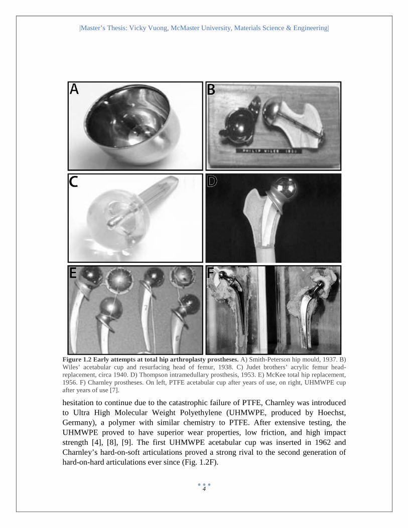
Figure 1.2 Early attempts at total hip arthroplasty prostheses. A) Smith-Peterson hip mould, 1937. B) Wiles’ acetabular cup and resurfacing head of femur, 1938. C) Judet brothers’ acrylic femur head-replacement, circa 1940. D) Thompson intramedullary prosthesis, 1953. E) McKee total hip replacement, 1956. F) Charnley prostheses. On left, PTFE acetabular cup after years of use, on right, UHMWPE cup after years of use [7].
hesitation to continue due to the catastrophic failure of PTFE, Charnley was introduced to Ultra High Molecular Weight Polyethylene (UHMWPE, produced by Hoechst, Germany), a polymer with similar chemistry to PTFE. After extensive testing, the UHMWPE proved to have superior wear properties, low friction, and high impact strength [4], [8], [9]. The first UHMWPE acetabular cup was inserted in 1962 and Charnley’s hard-on-soft articulations proved a strong rival to the second generation of hard-on-hard articulations ever since (Fig. 1.2F).
|Master’s Thesis: Vicky Vuong, McMaster University, Materials Science & Engineering|
5
1.3 The Modern Total Hip Arthroplasty The modern THA procedure is a reliable, minimally invasive, surgical remedy for patients that suffer from end-stage osteoarthritis (OA) [10]–[14], hip fractures [2], [15]–[18], or conditions that cause malfunction of the hip joint [10], [13], [14], [19], [20]. THA has a success rate of 10 years or longer, exceeding 95% survivorship in patients older than 75, effectively relieving pain and restoring function of the hip joint. Degenerative OA is the most prevalent form of arthritis caused by inflammation and degradation of the cartilage and it accounts for between 60 to 90% of primary diagnoses for THA (variable between different geographic populations) [11], [21]–[23]. The rates of THA have steadily increased since 1996 (Fig. 1.3) and internationally, over 1 million reported procedures are performed each year [21], [22], [24].
According to the National Joint Registry, of the 600 000 primary total hip replacement procedures documented in 2013, the median age of patients undergoing THA was 69 years. The increasing number of procedures is therefore largely driven by the increasing population of the elderly cohort; however, this is mainly an issue for economic burden rather than a concern for the development of implant materials and designs [25], [26]. The current challenge faced by researchers was well defined by Charnley during the early stages of THA development [27]:
“The challenge comes when patients between 45 and 50 years of age are to be considered for the operation, because then every advance in technical detail must be used if there is to be a reasonable chance of 20 or more years of trouble free activity” – Sir John Charnley
Recently, THA is emerging as a viable intervention for the treatment of etiologies causing hip disease in adolescents and young adults such as hip fracture, infection, congenital hip dysplasia (chronic dislocation cause by unstable hip joint), and juvenile idiopathic arthritis; especially when all non-operative treatments have been exhausted [13], [17], [28]–[30]. Generally, younger patients have higher expectations for faster post-surgical recovery, functional outcome, physical activities, and lifestyle [12], [26], [29]. This may result in the tendency to place higher, chronic loads on the implant, accelerating the failure of the hip prosthesis. The high risk of failure and poor longevity has historically deterred surgeons from offering this option to young patients. Efforts to prolong the service life of implant components are underway; they include but are not limited to, establishing optimal positioning of the prosthesis using computer-assisted navigation techniques, using more wear resistant bearing materials, using chemical and physical modifications to promote osseointegration, and many more [26]. Despite these advancements, as the demographic becomes younger, the likelihood of at least one or more revisions of the implant components, within the life expectancies of the patients, increases [30]. The rising number of THAs in young patients emphasizes the need for improvement in the durability and longevity of hip prostheses.

|Master’s Thesis: Vicky Vuong, McMaster University, Materials Science & Engineering|
6
Figure 1.3 Rates of THA. Historical International Trends in the THA Procedure Rate from Kurtz et al. 2010 [21][24].
1.4 Causes for Failure and Revision Surgery Despite the established successes of THA and the undeniable progression of new
designs, there remain short term and long term complications in the process. Some of the leading causes of failure (and reasons for revision surgery) include: aseptic loosening, component wear, osteolysis and instability [21]. A study investigating reasons for THA revisions established that the prevailing cause for failure is aseptic loosening (approximately 50% of all hip revisions). Long term, progressive failure mechanisms, such as aseptic loosening, are often asymptomatic in the early stages but ultimately result in grave clinical consequences. Overall, half of revision surgeries occurred within 5 years of the primary THA surgery [31]. Early failures are often related to surgical technique (e.g. component malposition) or contamination with bacteria, therefore the predominant causes for failure are instability (33% out of 118 hips) and deep infection (24% out of 118 hips) [31]. Secondary revision surgery requires the removal of the primary prosthesis followed by the replacement with a secondary prosthesis. Fixture and stabilization of the implant after the failure is typically more challenging and has less favorable clinical outcomes. Despite the classification for these clinical symptoms, the leading causes for failure/reasons for revision are not mutually exclusive and often interrelated.
In a simplified scenario, chronic loading (e.g. 10 to 20 years) of a prosthesis can result in the generation and accumulation of wear particles from the articulating surfaces of the implant components. The particulate debris released is engulfed by macrophages that initiate a cellular response in the form of chronic inflammation in the surrounding tissues leading to the recruitment of a wide array of cell types – amongst which are the osteoclasts, differentiated bone cells responsible for the resorption of bone matrix. The active resorption of bone as a result of wear debris is known as osteolysis (Fig. 1.4A). The progression of tissue destruction in the peripheral regions of the implant will ultimately lead to detachment of the prosthesis resulting in aseptic loosening (loosening of the implant in the absence of a bacterial infection) (Fig. 1.4B) [32]. Therefore, the risk factors for failure in THA are strongly dependent on the biomechanics (i.e. positioning
|Master’s Thesis: Vicky Vuong, McMaster University, Materials Science & Engineering|
7
and fit); the material selection (i.e. composition and tribology); and the biocompatibility of the prosthesis (i.e. immune reaction to wear debris).
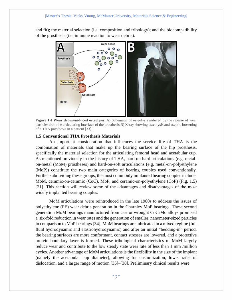
Figure 1.4 Wear debris-induced osteolysis. A) Schematic of osteolysis induced by the release of wear particles from the articulating interface of the prosthesis B) X-ray showing osteolysis and aseptic loosening of a THA prosthesis in a patient [33].
1.5 Conventional THA Prosthesis Materials An important consideration that influences the service life of THA is the
combination of materials that make up the bearing surface of the hip prosthesis, specifically the material selection for the articulating femoral head and acetabular cup. As mentioned previously in the history of THA, hard-on-hard articulations (e.g. metal-on-metal (MoM) prostheses) and hard-on-soft articulations (e.g. metal-on-polyethylene (MoP)) constitute the two main categories of bearing couples used conventionally. Further subdividing these groups, the most commonly implanted bearing couples include: MoM, ceramic-on-ceramic (CoC), MoP, and ceramic-on-polyethylene (CoP) (Fig. 1.5) [21]. This section will review some of the advantages and disadvantages of the most widely implanted bearing couples.
MoM articulations were reintroduced in the late 1980s to address the issues of polyethylene (PE) wear debris generation in the Charnley MoP bearings. These second generation MoM bearings manufactured from cast or wrought CoCrMo alloys promised a six-fold reduction in wear rates and the generation of smaller, nanometer-sized particles in comparison to MoP bearings [34]. MoM bearings are lubricated in a mixed regime (full fluid hydrodynamic and elastrohydrodynamic) and after an initial “bedding-in” period, the bearing surfaces are more conformant, contact stresses are lowered, and a protective protein boundary layer is formed. These tribological characteristics of MoM largely reduce wear and contribute to the low steady state wear rate of less than 1 mm3/million cycles. Another advantage of MoM articulations is the flexibility in the size of the implant (namely the acetabular cup diameter), allowing for customization, lower rates of dislocation, and a larger range of motion [35]–[38]. Preliminary clinical results were

|Master’s Thesis: Vicky Vuong, McMaster University, Materials Science & Engineering|
8
Figure 1.5 Bearing Surfaces for Hip Replacements, 2010-2011. N = 11 948 hip bearing surfaces [21]
promising, restoring the popularity of MoM bearings. However, clinical studies in the early 2000s began to report high serum levels and periprosthetic accumulation of cobalt and chromium ions, metal hypersensitivity and rapidly progressing osteolysis in patients with second generation MoM hip implants [39]–[43]. The adverse biological reactions to the metal debris resulted in high rates of revision and consequently, the drastic decrease in the rate of implantation of MoM bearings since 2005 [21].
Tissue reactions to wear particle generation have motivated researchers to seek out a more wear resistant, biocompatible material. The newest qualifying contestants, introduced about 40 years ago, are the prostheses containing ceramic bearing surfaces. Historically, Alumina (Al2O3) and Zirconia (ZrO2), were the ceramics used for THA prostheses in either a hard-on-hard, CoC articulation or a hard-on-soft, CoP articulation [44]. Ceramics as a bearing material feature, low friction; high surface wettability; fluid-film lubrication; extremely low wear rates (up to 50 times less than conventional PE); and generation of few, bio-inert, nanometer-sized wear debris (up to thousands of times smaller than PE) [30], [45]–[47]. The outstanding tribological properties of ceramic prostheses limit the risks of periprosthetic osteolysis making it a promising alternative to MoM or MoP couplings, especially for younger recipients. The major compromise to the high modulus of ceramic materials is its intrinsic brittleness. Under cyclic loading, the hardness of the ceramic hampers plastic deformation; microscopic imperfections in the material increase stress, leading to the propagation of cracks [48], [49]. As a result, both ceramic acetabular cups and ceramic femoral heads are highly prone to catastrophic fractures (Fig. 1.6) [48]. Newer generation ceramics are composite materials (e.g. Biolox® Delta which is composed of yttria stabilized tetragonal zirconia polycrystals (Y-TZP)) that reduce mechanical failure via crack resistance, greater fracture toughness and even lower wear rates [50]–[53]. Despite the introduction of three generations of ceramics, catastrophic failure of the ceramic components has not been entirely eliminated.
|Master’s Thesis: Vicky Vuong, McMaster University, Materials Science & Engineering|
9
Moreover, meta-analysis of clinical outcomes show no superiority of the new hard-on-hard bearing couples over MoP articulations [54], [55] and problems with osteolysis and aseptic loosening still exist.
In lieu of the self-mating articulations seen in hard-on-hard prostheses, MoP prostheses commonly consist of an ultra-high molecular weight polyethylene (UHMWPE) or highly cross-linked UHMWPE (HXLPE) acetabular cup coupled to a CoCrMo alloy femoral head. UHMWPE is a polymer that provides reasonably low friction, wear resistance, and high impact strength (relative to other polymers) [9], [56]–[59]. From a clinical perspective, polyethylene acetabular cups coupled to metallic ceramic femoral heads are the most conservative material choice for THA due to its predictable, long-term, clinical performance. Yet, aseptic loosening resulting from PE and metallic wear debris remains an obstacle to the efficacy and service life of MoP articulations. The complex microstructure of UHMWPE and consequently, its mechanical properties can be controlled by processing, thermal and radiation exposure, sterilization and storage. Over the past few decades, enhancements to improve the wear resistance of conventional UHMWPE has been underway, starting with crosslinking by sterilization with gamma irradation (20-33 kGy) [60]–[63], chemical-induced crosslinking using a free-radical-generating chemical, and silane compound-induced crosslinking [64]. Hip simulator and short term clinical studies (2 to 5 years follow-up) of HXLPE have demonstrated an improvement in volumetric wear rates, however, long term clinical results are required to to validate whether HXLPE is a better alternative for UHMWPE [63].
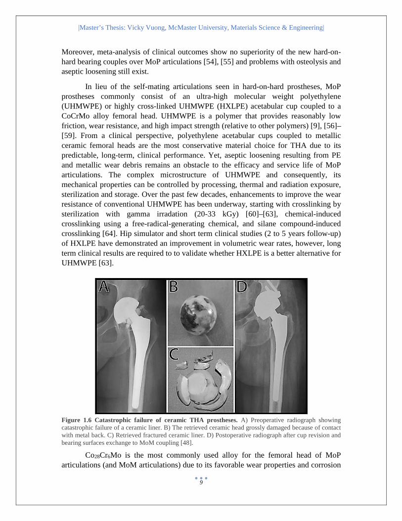
Figure 1.6 Catastrophic failure of ceramic THA prostheses. A) Preoperative radiograph showing catastrophic failure of a ceramic liner. B) The retrieved ceramic head grossly damaged because of contact with metal back. C) Retrieved fractured ceramic liner. D) Postoperative radiograph after cup revision and bearing surfaces exchange to MoM coupling [48].
Co28Cr6Mo is the most commonly used alloy for the femoral head of MoP articulations (and MoM articulations) due to its favorable wear properties and corrosion

|Master’s Thesis: Vicky Vuong, McMaster University, Materials Science & Engineering|
10
resistance. The CoCrMo alloy may also contain traces of nickel, manganese or iron. There are two different manufacturing methods, that create two chemically identical cobalt alloys, with different mechanical properties – wrought (ISO 5832-12, ASTM F1537) and cast (ISO 5832-4, ASTM F75) alloys. The materials can be further classified as low carbon (lc < 0.15%) and high carbon (hc ≥ 0.15%), however the classification of carbon content is typically defined within a range (e.g. low carbon is between 0 – 0.14%). The carbon content can have effects on the metallurgical properties and microstructure of the resultant alloy. Wrought alloys have a grain size of 15 – 20 µm and in low carbon content alloys, are monophasic and purely austenitic (face-centered cubic). Increases in carbon content give rise to chromium and molybdenum carbides that cover 5% of the alloy surface area. Under loading, stress-induced face-centered cubic to hexagonal close packed martensitic transformation occurs, hardening the material and improving tribological properties. Cast alloys on the other hand, have a much coarser microstructure than wrought alloys with a grain size of 2 000 µm. The size of carbides is about one order of magnitude larger than the carbides found in wrought alloys and the size and number increases with increasing carbon content. The microstructure of cast alloys often exhibit pores or holes, resulting in reduced mechanical properties. Closure of these porosities in “as cast” (i.e. non heat-treated) components can be achieved by hot isostatic pressing and solution annealing. Heat treatment markedly reduces carbide content and can cause the block M7C3-type carbides to dissolve, leading to the formation of M7C3-type carbides [65]–[67].
Wear particle generation, even in the more robust bearing combinations, emphasizes that wear is inevitable at the articulating interface. Therefore tribological investigations, such as friction, lubrication and wear, of the articulating system are paramount in the understanding of failure mechanisms. The development of new, alternative materials have significantly lowered volumetric wear rates, but paradoxically, the number of wear particles produced have also increased 100-fold [68]–[71]. Furthermore, the nanometer-sized particles generated from the new bearing materials introduce novel issues such as elevated bioreactivty and the dispersion of particles to systemic tissues via the blood stream [63]. In the case of PE, the critical size range between 0.3 – 10 µm was found to be the most biologically active, as the particles could be phagocytosed by macrophages [71]. In addition, the reduced size of the particles increases available surface area for corrosion processes to occur [71]. The overall performance of the bearing couples in the complex physiological environment of the hip joint is dependent not only on the volumetric wear rates but also on the size and morphology of the wear debris generated.
The adverse physiological reactions to wear particles highlight the importance of meticulous and physiologically relevant investigations of the failure mechanisms – from the macroscopic to the microscopic level. An understanding of wear processes requires the correlation between surface tribology and subsurface microstructural changes. As a result of catastrophic failures, extensive research was performed for MoM articulations. Researchers have found that the predominant wear mechanisms at the MoM prosthesis
|Master’s Thesis: Vicky Vuong, McMaster University, Materials Science & Engineering|
11
interface include abrasion, surface fatigue, and tribochemical reactions [69], [72]–[74]. As mentioned previously, the observation of a protective boundary layer (aka. tribological layer) is thought to serve as a lubricating barrier to reduce direct contact between the surfaces and thus minimize the effects of adhesive wear [72]. However, the mechanism of formation and precise composition of this layer is highly controversial and remains inconclusive. There is a large enrichment of carbon in the layer suggesting that its origin is organic and protein derived [75]. However, the use of transmission electron microscopy (TEM) and electron energy loss spectroscopy (EELS) has found that the layer may be graphitic in nature and therefore not entirely biological [76], [77]. The knowledge acquired from research on MoM hip implants is a foundation for the understanding wear mechanisms that may similarly drive the failure of other bearing combinations.

|Master’s Thesis: Vicky Vuong, McMaster University, Materials Science & Engineering|
12
Research Motivation MoP THA protheses are the most reliably implanted bearing combinations,
rivaling the clinical performance of many alternatives for over half a century. In light of MoP articulations, the modern focus of research is on modifications to the polymeric counterpart, with aims to reduce the release of PE wear debris [78]–[80]. Abrasion of the UHMWPE acetabular cup against the CoCrMo femoral head during articulation is the primary mechanism for the generation of PE wear debris in vivo [70]. High blood metal ion levels (cobalt or chromium) are not unheard of in patients with MoP hip implants, however, the resultant adverse physiological reaction is consistently attributed to the corrosion at nonarticulating junctions of the prosthesis (e.g. the tapered stem or bone screws) [81]. Presumably, wear of the metallic femoral component is also likely to occur; at which stage it could act to exacerbate the wear on the PE counterpart and facilitate third-body abrasion back onto the metallic surface. The extensive investigations of wear on MoM CoCrMo components, although relevant, may not be entirely generalizable to the CoCrMo femoral head component in MoP hip prostheses since they operate under unique lubrication regimes. Consequently, the analysis of wear on the metallic component of MoP articulations cannot be overlooked.
The objective of this research is to examine the surface wear, tribological layer and subsurface microstructure of MoP THA prostheses using advanced electron microscopy techniques. The analysis of failed MoP hip implant retrievals in conjunction with unused manufacturer references, will provide physiologically relevant insight on in vivo conditions and account for manufacturing by-products that preexist implantation. Moreover, the results will be compared to previous studies on MoM articulations to help elucidate common, as well as unique wear mechanisms in each system. Logically, it is hypothesized that the femoral head retrieval samples will reveal greater surface and subsurface damage such as scratches and/or changes in the subsurface microstructure as a result of in vivo articulations in comparison to the reference samples. Furthermore, it is hypothesized that although many aspects of wear on the metallic surface will be similar between MoP and MoM articulations, the contributions of the UHMWPE may influence the depth of the scratches, the lubrication, the formation of a boundary tribological layer and changes in the subsurface microstructure. To prevent the recurrence of past catastrophic failures, the ambitious endeavors to develop superior, alternative prosthetic materials must be accompanied by vigorous clinically-relevant testing of the new material in combination to the comprehensive understanding of how a conventional model, such as MoP, may wear.
Summary of Research Objectives: Examine surface and subsurface features of MoP THA prostheses using electron
microscopy techniques. Compare results between references and retrievals to differentiate the effects of
manufacturing and in vivo wear and compare results from this study to research on MoM THA prostheses to elucidate the difference between the two systems.
|Master’s Thesis: Vicky Vuong, McMaster University, Materials Science & Engineering|
13
CHAPTER 2 Experimental Methods 2.1 Samples and Sample Preparation
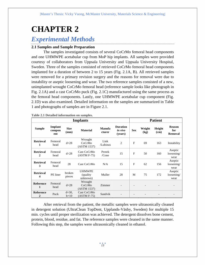
The samples investigated consists of several CoCrMo femoral head components and one UHMWPE acetabular cup from MoP hip implants. All samples were provided courtesy of collaborators from Uppsala University and Uppsala University Hospital, Sweden. Three of the samples consisted of retrieved CoCrMo femoral head components implanted for a duration of between 2 to 15 years (Fig. 2.1A, B). All retrieved samples were removed for a primary revision surgery and the reasons for removal were due to instability or aseptic loosening and wear. The two reference samples consisted of a new, unimplanted wrought CoCrMo femoral head (reference sample looks like photograph in Fig. 2.1A) and a cast CoCrMo puck (Fig. 2.1C) manufactured using the same process as the femoral head components. Lastly, one UHMWPE acetabular cup component (Fig. 2.1D) was also examined. Detailed information on the samples are summarized in Table 1 and photographs of samples are in Figure 2.1. Table 2.1 Detailed information on samples.
After retrieval from the patient, the metallic samples were ultrasonically cleaned in detergent solution (UltraClean TopDent, Upplands-Väsby, Sweden) for multiple 15 min. cycles until proper sterilization was achieved. The detergent dissolves bone cement, protein, blood, residue, and fat. The reference samples were cleaned in the same manner. Following this step, the samples were ultrasonically cleaned in ethanol.
Implants Patient
Sample
Implant compon
ent
Size (mm) Material Manufa
cturer
Duration in vivo (years)
Sex Weight (kg)
Height (cm)
Reason for
Removal
Retrieval 1
Femoral head d=28
Wrought CoCrMo
(ASTM 1537)
Link /Lubinus 2 F 69 163 Instability
Retrieval 2
Femoral head d=28 Cast CoCrMo
(ASTM F-75) Protek /Cone 15 F 50 160
Aseptic loosening/
wear
Retrieval 3
Femoral head 28 Cast CoCrMo N/A 15 F 62 156
Aseptic loosening/
wear
Retrieval 4 PE liner broken
pieces
UHMWPE (quality
unknown) Muller 28 M 75 172
Aseptic loosening/
wear
Reference 1
Femoral head d=28
Wrought CoCrMo
(ASTM 1537) Zimmer - - - - -
Reference 2 Puck d=30,
h=10 Cast CoCrMo (ASTM F-75) Sandvik - - - - -

|Master’s Thesis: Vicky Vuong, McMaster University, Materials Science & Engineering|
14
Figure 2.1 Photographs of samples. A) Explant 1, CoCrMo femoral head (Explant 2 and Reference 1 look identical in photographs). B) Explant 3, CoCrMo femoral head. C) Reference 2, CoCrMo puck. D) Explant 4, UHMWPE acetabular cup fragments. E) Explant 1, after EDM cutting. SM is the superior medial region and L is the lateral region F) Explant 3, after EDM cutting. L is the lateral region.
Upon arrival at McMaster University, the metallic samples were rinsed with detergent for 5 min., washed with distilled water, ultrasonically washed in acetone for 5 min., ultrasonically washed in methanol for 5 min. and allowed to air dry. Then the samples were cut using electrical discharge machining (EDM) in the transverse plane to minimize the size of the samples (approximately 16 mm diameter by 4 mm height, Fig. 2.1E, F) for insertion into the auger electron spectroscopy (AES) microscope sample holder. The cutting also allowed for stabilization of the sample during higher tilt angles in the focused ion beam (FIB) microscope. The superior, medial region of the samples were coated with nail lacquer to protect the surface from damage in the EDM process. To remove contamination from the EDM process and reduce charging prior insertion into the focused ion beam (FIB), samples were ultrasonically washed in acetone for 5 min., ultrasonically washed in methanol for 5 min. and allowed to air dry. For further analysis

|Master’s Thesis: Vicky Vuong, McMaster University, Materials Science & Engineering|
15
using transmission electron microscopy (TEM), the superior, medial region of the femoral head samples were analyzed to maintain consistency in the investigated areas of interest since in vivo loading conditions were uncertain and likely inconsistent between samples. The base of the sample remaining from the cut was used for analysis of bulk microstructure using etchants, light microscopy (LM) and scanning electron microscopy (SEM).
The UHMWPE acetabular cup was sterilized and desiccated at Uppsala University. Smaller sections of the sample were removed at McMaster University with a small hand-held saw to ease mounting of the sample and reduce effects of curvature of the sample in the SEM. Prior to examination in the electron microscopes to prevent charging effects, the surface of the PE sample was either coated in a protective layer of gold or carbon.
2.2 Ultramicrotomy In addition to FIB preparation of the UHMWPE sample for TEM, the UHMWPE
was ultramicrotomed using a diamond knife. Four preparations of the UHMWPE were examined: 1) unstained UHMWPE sample, 2) pre-staining with chlorosulphonic acid, 3) post-staining with uranyl acetate and 4) pre-staining with chlorosulphonic acid in combination to post-staining with uranyl acetate. A small piece of the UHMWPE retrieval (approximately 3 mm by 10mm) was stained using chlorosulphonic acid (99% concentration) for 6 hours. The chlorosulphonic acid stains crosslinks and stabilizes the amorphous regions of the UHMWPE. After the acid staining, the UHMWPE sample was rinsed with acetone then distilled water to remove excess stain. The sample was then allowed to dry at room temperature. The samples were then embedded in epoxy resin and cured at 60° for 24 hours. Post-staining of the UHMWPE sample to enhance contrast prior to TEM consisted of staining with 0.2% aqueous solution of uranyl acetate for 3 hours. Cryo-ultramicrotomy was also attempted to decrease the fragility of the sample during sectioning however, the edges of the sample continued to curl under and did not maintain the integrity of the sample at the surface.
2.3 Scanning Electron Microscopy To examine surface characteristics, all samples were investigated using the JEOL
JSM-6610LV (JEOL, Japan) tungsten filament SEM. The microscope was operated at accelerating voltages between 2 keV to 15 keV and beam currents of 40 to 60 pA depending on the sample and the characteristics of interest. The secondary electron imaging (SEI) mode and back-scattered electron (BSE) imaging mode were simultaneously used to analyze surface topography and elemental compositional contrast. Energy dispersive X-ray spectroscopy (EDS) analysis was also used to perform point identifications, line-scans and elemental mapping on the surface of the samples.
For analysis of the UHMWPE sample (Explant 4), to prevent beam damage on the sample, either lower accelerating voltages in high vacuum were used or higher accelerating voltages in low vacuum were used. EDS analysis on this sample was also done at higher magnifications to search for micron-sized wear particles on the surface.

|Master’s Thesis: Vicky Vuong, McMaster University, Materials Science & Engineering|
16
2.4 Auger Electron Spectroscopy Auger electron spectroscopy (AES) on a JEOL JAMP 9500F (JEOL, Japan) Field
Emission Auger Microprobe was used to perform depth profiling on the surface of the metallic samples to characterize the potential presence of a tribological layer. Depth profiling conditions were at 10 keV, 50nA, 0.75 eV step size, 5 sweeps and 100 ms dwell time. The estimated sputtering rate was 30 nm/min as extrapolated from the JEOL JAMP-9500 Instruction Manual Appendix 9: Ion Beam Etch and Sputtering Rate. The sputtering rate of CoCrMo was estimated using the approximate average of sputtering rates of CoCr and Mo.
2.5 Focused Ion Beam To isolate specific sites of interest (such as under scratches) for cross-sectional
examination of subsurface microstructure using the transmission electron microscope (TEM), conventional focused ion beam (FIB) milling procedures were performed using the Zeiss NVision 40 (Carl Zeiss, Germany) FIB SEM (equipped with a Schottky Field Emission Gun). Regions of interest on the CoCrMo reference samples were selected based on scratches present as a result of the manufacturing process. Regions of interest on the CoCrMo explants were selected based on locations where deeper, nonlinear scratches, which are suggestive of in vivo wear, were present and if possible, the simultaneous presence of what appeared to be a residual tribological layer on the surface. A protective layer of carbon (approximately 1 to 2 µm thick) followed by a thin layer of tungsten was deposited over areas of interest to prevent ion beam damage from the bulk milling procedure. Trenches were milled around the area of interest using a 30 keV beam of Ga+ ions. The lamella was then milled to detach it from the bulk sample, lifted out by a micromanipulator, attached onto a copper grid and thinned to electron transparency with a 10 keV beam. Two cross-section TEM samples were prepared for Explants 2 and 3 and one cross-section TEM sample was examined for all other samples. A TEM sample was also prepared for Explant 4 (UHMWPE sample) and the area of interest was chosen over a relatively flat surface since the thin pieces of flaky polymer were easily damaged under the beam (Fig. 2.2).
2.6 Transmission Electron Microscopy Transmission Electron microscopy was used to examine the subsurface
microstructure and chemical composition of all samples. A Philips CM12 (FEI, The Netherlands) with LaB6 filament (120 keV) was used for preliminary imaging of subsurface microstructure. A JEOL 2010F (JEOL, Japan) field emission TEM/STEM was operated at 200 keV for EDS mapping and bright-field scanning transmission electron microscopy (STEM) of all samples. A FEI Titan 80-300HB (FEI, The Netherlands) operated at 300 keV was used for electron energy loss spectroscopy (EELS) analysis of the tribological layer on Retrieval 3.

|Master’s Thesis: Vicky Vuong, McMaster University, Materials Science & Engineering|
17
Figure 2.2 Focused ion beam preparation of TEM samples. A) Example of area selection for Reference 1 over shallow manufacturing-induced scratches. B) Example of area selection for Explant 2 over deeper irregular scratches. C) Areas of interest are coated with a protective layer of carbon and tungsten. D) Trenches around the area of interest are milled using the Ga+ ion beam. E) A micromanipulator is used to extract the TEM sample and attach it onto a TEM grid. F) TEM sample is then thinned to electron transparency for the TEM.

|Master’s Thesis: Vicky Vuong, McMaster University, Materials Science & Engineering|
18
CHAPTER 3 Results and Discussion: Surface Characterization Surface Characterization
At first glance with the unaided eye, the CoCrMo femoral heads (retrievals and references) appeared to be polished to a mirror finish (Fig. 2.1). However, at the micro- and nanoscopic level (light microscopy and electron microscopy), many imperfections were observed on the surface of unused references and retrievals alike. To maintain consistency, the majority of investigated sites were chosen on the superior, medial region of the metallic samples since in vivo loading conditions on the retrievals were unknown and likely variable between patients (Fig. 2.1E, F).
3.1 Scratches In the SEM, even at low magnifications, scratches were clearly visible on the surface of the reference and retrieval samples. The scratch patterns on the unused reference samples (Fig. 3.1A, B and Fig. 3.2A, B) consisted of shallow, straight, parallel and/or perpendicular scratches. In comparison, the surface of the retrievals (Fig. 3.1C, D and Fig 3.2C – F) were more highly worn and consisted of more abundant, deeper and non-linear scratches in addition to the shallow, uniform scratches seen in the reference samples. Notably, the abundance of scratches on Retrieval 1 was much less than on Retrievals 2 and 3. This may be attributed to the duration of time the prosthesis was in service, Retrieval 1 was implanted for a much shorter length of time compared to the other two prostheses (Table 1). Also, the distribution of scratches on the retrievals is greater on the lateral regions of the samples compared to the top (Fig. 2.1E), as observed with SEM. Complementary VSI analysis (performed by a collaborating researcher) on the lateral regions and tops of the same samples revealed that scratches were more prevalent on the sides and that the approximate range of scratch depths were up to 150 nm on the retrievals while the maximum depth on the reference samples was 60 nm [82].
The reference samples have not been implanted and thus imperfections present on the surface were likely formed during the proprietary manufacturing processes. Additionally, imperfections observed on the surface of the reference samples are presumably representative of similar imperfections found on general prostheses prior to implantation in patients. Therefore, the surface wear on the retrieved samples can be attributed to both the manufacturing process and in vivo conditions in the patient body. The shallow, uniform scratches present on both the reference and retrieval samples are suggestive of single-cycle deformation abrasive wear modes (e.g. mechanical polishing step of the manufacturing procedure) [83], [84]. Conversely, the deeper, nonlinear individual scratches may be suggestive of third-body abrasive wear modes (e.g. torn off metallic particles in between the articulating space of the implant components) [70], [83] while the more abundant, complex wear scars and cracks may be a result of repeated-cycle deformation wear mechanisms [83], [84]. The pre-existing scratches observed on the references may have an influence on the wear modes and tribochemical reactions in

|Master’s Thesis: Vicky Vuong, McMaster University, Materials Science & Engineering|
19
Figure 3.1 SEM of the surface of wrought femoral head samples. A) and B) SEI and BEC micrographs, respectively, of the surface of Reference 1. Scratches are shallow, linear and uniform. C) and D) SEI and BEC micrographs, respectively, of the surface of Retrieval 1. Deeper, more abundant, irregular scratches are visible on the surface.
the mechanical and biochemical environment of the in vivo joint such as exacerbating abrasive wear on the articulating interface of the UHMWPE acetabular component or acting as a reservoir for wear particles [85]. Furthermore, pre-existing scratches and scratches formed during in vivo wear may have an effect on the shape, size and quantity of wear debris (polyethylene as well as metallic wear particles) generated. Presumably, scratches due to in vivo wear will be more abundant in high contact zones (such as on the lateral sides of the prostheses) and areas that endure the greatest loads leading to greater contact pressures. Therefore the discussion pertaining to scratches observed in this study (only on superior, medial regions of the samples) may be an underestimation of the extent of scratch morphology and abundance over the entire surface of the implant.
|Master’s Thesis: Vicky Vuong, McMaster University, Materials Science & Engineering|
20
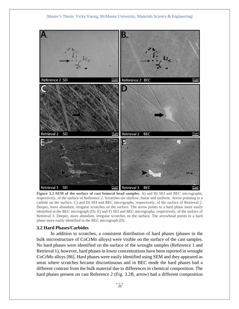
Figure 3.2 SEM of the surface of cast femoral head samples. A) and B) SEI and BEC micrographs, respectively, of the surface of Reference 2. Scratches are shallow, linear and uniform. Arrow pointing to a carbide on the surface. C) and D) SEI and BEC micrographs, respectively, of the surface of Retrieval 2. Deeper, more abundant, irregular scratches on the surface. The arrow points to a hard phase more easily identified in the BEC micrograph (D). E) and F) SEI and BEC micrographs, respectively, of the surface of Retrieval 3. Deeper, more abundant, irregular scratches on the surface. The arrowhead points to a hard phase more easily identified in the BEC micrograph (D).
3.2 Hard Phases/Carbides In addition to scratches, a consistent distribution of hard phases (phases in the bulk microstructure of CoCrMo alloys) were visible on the surface of the cast samples. No hard phases were identified on the surface of the wrought samples (Reference 1 and Retrieval 1), however, hard phases in lower concentrations have been reported in wrought CoCrMo alloys [86]. Hard phases were easily identified using SEM and they appeared as areas where scratches became discontinuous and in BEC mode the hard phases had a different contrast from the bulk material due to differences in chemical composition. The hard phases present on cast Reference 2 (Fig. 3.2B, arrow) had a different composition
|Master’s Thesis: Vicky Vuong, McMaster University, Materials Science & Engineering|
21
and morphology from the hard phases observed on Retrieval 2 and Retrieval 3 (Fig. 3.2D, F arrows and arrowheads, respectively). The Reference 2 hard phases appeared as clusters of smaller phases approximately 50 – 100 µm across whereas the hard phases on the cast retrievals appeared as individual structures ranging from 5 to 50 µm in length.
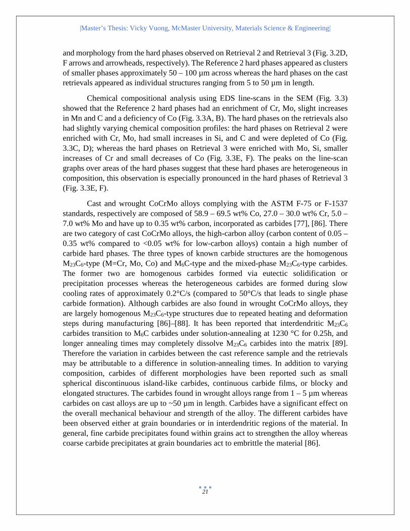
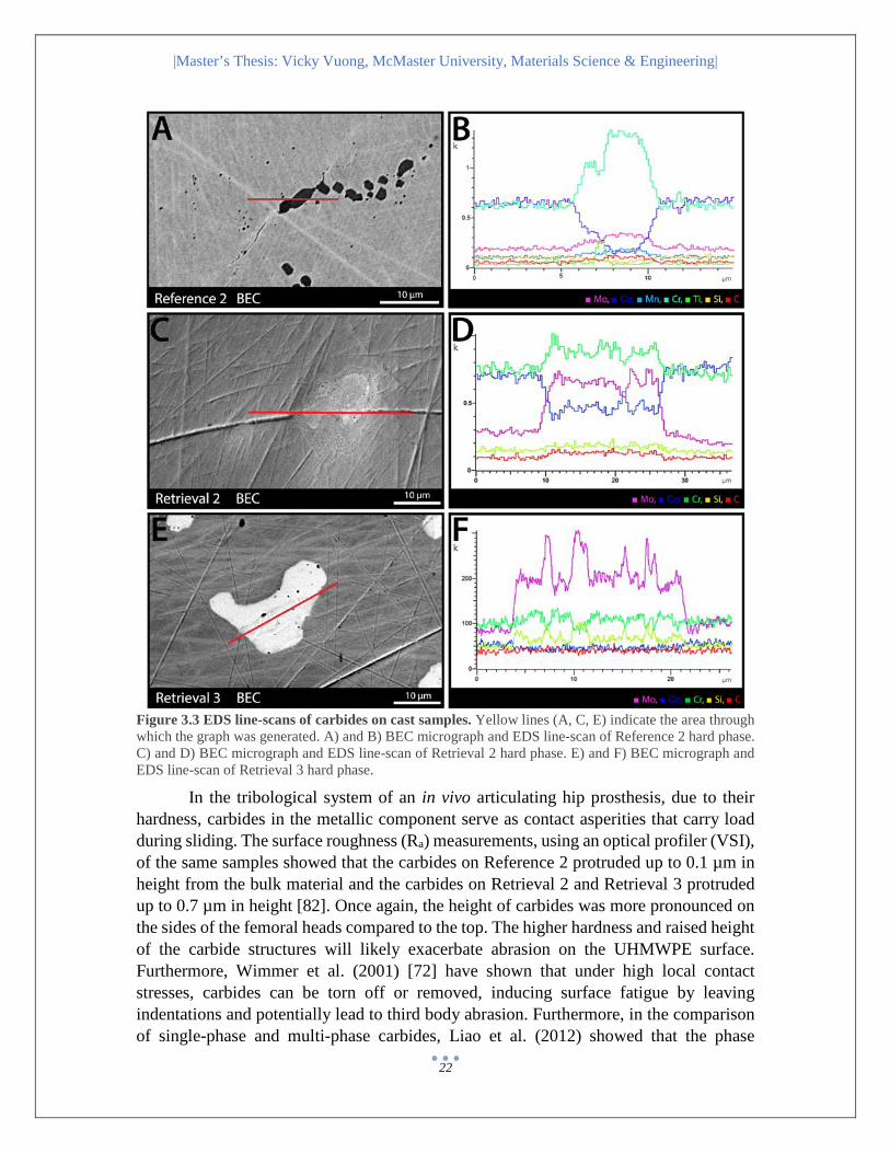
Chemical compositional analysis using EDS line-scans in the SEM (Fig. 3.3) showed that the Reference 2 hard phases had an enrichment of Cr, Mo, slight increases in Mn and C and a deficiency of Co (Fig. 3.3A, B). The hard phases on the retrievals also had slightly varying chemical composition profiles: the hard phases on Retrieval 2 were enriched with Cr, Mo, had small increases in Si, and C and were depleted of Co (Fig. 3.3C, D); whereas the hard phases on Retrieval 3 were enriched with Mo, Si, smaller increases of Cr and small decreases of Co (Fig. 3.3E, F). The peaks on the line-scan graphs over areas of the hard phases suggest that these hard phases are heterogeneous in composition, this observation is especially pronounced in the hard phases of Retrieval 3 (Fig. 3.3E, F).
Cast and wrought CoCrMo alloys complying with the ASTM F-75 or F-1537 standards, respectively are composed of 58.9 – 69.5 wt% Co, 27.0 – 30.0 wt% Cr, 5.0 – 7.0 wt% Mo and have up to 0.35 wt% carbon, incorporated as carbides [77], [86]. There are two category of cast CoCrMo alloys, the high-carbon alloy (carbon content of 0.05 – 0.35 wt% compared to <0.05 wt% for low-carbon alloys) contain a high number of carbide hard phases. The three types of known carbide structures are the homogenous M23C6-type (M=Cr, Mo, Co) and M6C-type and the mixed-phase M23C6-type carbides. The former two are homogenous carbides formed via eutectic solidification or precipitation processes whereas the heterogeneous carbides are formed during slow cooling rates of approximately 0.2°C/s (compared to 50°C/s that leads to single phase carbide formation). Although carbides are also found in wrought CoCrMo alloys, they are largely homogenous M23C6-type structures due to repeated heating and deformation steps during manufacturing [86]–[88]. It has been reported that interdendritic M23C6
carbides transition to M6C carbides under solution-annealing at 1230 °C for 0.25h, and longer annealing times may completely dissolve M23C6 carbides into the matrix [89]. Therefore the variation in carbides between the cast reference sample and the retrievals may be attributable to a difference in solution-annealing times. In addition to varying composition, carbides of different morphologies have been reported such as small spherical discontinuous island-like carbides, continuous carbide films, or blocky and elongated structures. The carbides found in wrought alloys range from 1 – 5 µm whereas carbides on cast alloys are up to ~50 µm in length. Carbides have a significant effect on the overall mechanical behaviour and strength of the alloy. The different carbides have been observed either at grain boundaries or in interdendritic regions of the material. In general, fine carbide precipitates found within grains act to strengthen the alloy whereas coarse carbide precipitates at grain boundaries act to embrittle the material [86].
|Master’s Thesis: Vicky Vuong, McMaster University, Materials Science & Engineering|
22
Figure 3.3 EDS line-scans of carbides on cast samples. Yellow lines (A, C, E) indicate the area through which the graph was generated. A) and B) BEC micrograph and EDS line-scan of Reference 2 hard phase. C) and D) BEC micrograph and EDS line-scan of Retrieval 2 hard phase. E) and F) BEC micrograph and EDS line-scan of Retrieval 3 hard phase.
In the tribological system of an in vivo articulating hip prosthesis, due to their hardness, carbides in the metallic component serve as contact asperities that carry load during sliding. The surface roughness (Ra) measurements, using an optical profiler (VSI), of the same samples showed that the carbides on Reference 2 protruded up to 0.1 µm in height from the bulk material and the carbides on Retrieval 2 and Retrieval 3 protruded up to 0.7 µm in height [82]. Once again, the height of carbides was more pronounced on the sides of the femoral heads compared to the top. The higher hardness and raised height of the carbide structures will likely exacerbate abrasion on the UHMWPE surface. Furthermore, Wimmer et al. (2001) [72] have shown that under high local contact stresses, carbides can be torn off or removed, inducing surface fatigue by leaving indentations and potentially lead to third body abrasion. Furthermore, in the comparison of single-phase and multi-phase carbides, Liao et al. (2012) showed that the phase

|Master’s Thesis: Vicky Vuong, McMaster University, Materials Science & Engineering|
23
boundaries within multi-phase carbides in cast samples are sources of crack propagation and fractures after 5 million cycles in a simulator test. However, no discernible fractures were observed in the single-phase carbides in the wrought alloy. The presence of hard phases and carbon content also has an effect on the passivity of the alloy. The preferential metallic dissolution at hard phase boundaries depletes the metal matrix in Cr and Co, thus hindering the availability of Cr to form an oxide film [90]. While single-phase hard phases tend to strengthen the alloy material, multi-phase hard phases can encourage abrasive wear and surface wear on the UHMWPE counter-interface as well as on the metallic surface itself. Further tribochemical consequences such as the effect on wear particle generation from hard phases, will be discussed in the subsurface discussions of hard phases later in the Results and Discussion.
3.3 Tribological Layer At lower accelerating voltages (e.g. 5 – 10 keV) in SEI mode, a residual layer was evident on the surface of Retrievals 2 and 3 (Fig. 3.2 C, E). The layer consists of darker and brighter areas and appears to cover the consistently distributed hard phases (Fig. 3.2 D, F). This residual layer was only observed to a slight extent on Retrieval 1 (perhaps due to the short duration of implantation prior to failure) and was not observed on the References although all samples were generally cleaned the same way. To investigate and characterize this layer, AES was employed due to its low interaction volume and surface sensitivity.
Points of interest on the surface of all samples analyzed using AES are presented in Figure 3.4. For Reference 1, the slightly darker patch (+2) compared to the bulk area (+1) showed a slight increase of C composition (Fig. 3.4 A). In addition there was 20 – 30% O on the two areas suggesting the presence of an oxide layer (Fig. 3.4 A). On the surface of Retrieval 1 there were areas of darker and brighter patches as mentioned above as characteristic of the ‘residual layer’ (Fig. 3.4 B). The darker area (+2) had a greater composition of C compared to the bulk area (+1) whereas the brighter area (+3) corresponded to a slightly greater amount of Cr.
Predictably, there was a lack of an evident residual surface layer on the cast Reference 2 sample (Fig. 3.5A), however, comparing the elemental composition between the hard phase (+1) and the bulk material (+2), the hard phase had higher amounts of C, O, Cr, Mo and a lower amount of Co. These values were consistent with the previously discussed SEM EDS line-scan profile of a Reference 2 carbide (Fig. 3.3A, B). For cast Retrieval 2, the point spectra were taken over areas with deep scratches (Fig 3.5B, asterix (*)) however the results were not notably different from the bulk and therefore not displayed in the figure (Fig. 3.5B). The hard phase (+2) compared to the bulk (+1) was slightly more abundant in C, Cr, had a greater increase in Mo, Si and a depletion of O and Co, again consistent with previous SEM EDS results. The brighter area (+3) of Retrieval 2 compared to the bulk had a decrease in C and O but had a slight increase in the amounts of Cr, Mo, and Si (Fig. 3.5C). The darker area (+4) on Retrieval 2 had greater amounts of O and Si compared to the bulk area (Fig. 3.5C). Lastly, on

|Master’s Thesis: Vicky Vuong, McMaster University, Materials Science & Engineering|
24
Retrieval 3, compared to the bulk, the hard phase (+2) had an increase in C, O, Mo and a decrease in Co, and a slight decrease in Cr, these results are similar to those obtained in the SEM EDS line-scans. The brighter area (+3) had a greater amount of Co and the darker area (+4) had a much greater amount of C (Fig. 3.5D).
Figure 3.4 AES point analysis of wrought samples. The numbers (e.g. +1, +2, +3) indicate points at which compositional analysis was taken. The bulk areas correspond to areas where the contrast is representative of the majority of the surface. Elemental compositions at the points of interest are presented in atomic percentage (at%) in the table below. The highlighted values are increases in elemental composition in comparison to the bulk values. The detection limit for EDS is approximately ±0.5 at%. The highlighted values are increases in elemental composition in comparison to the bulk values.
Overall, it appears that brighter areas in the surface layer corresponded to an abundance of Cr, Mo, or Co and the darker areas generally corresponded to an abundance of C or O. The relative abundance of elements in the hard phases of the cast samples corresponded well to the relative elemental compositions from the SEM EDS line-scans.

|Master’s Thesis: Vicky Vuong, McMaster University, Materials Science & Engineering|
25
Figure 3.5 AES point analysis of cast samples. The numbers (e.g. +1, +2, +3) indicate points at which compositional analysis was taken. The bulk areas correspond to areas where the contrast is representative of the majority of the surface. B) * point spectra were taken over scratches however the compositions were not notably different from the bulk material, therefore not included in the table. Elemental compositions at the points of interest are presented in atomic percentage (at%) in the table below. The highlighted values are increases in elemental composition in comparison to the bulk values. The detection limit for EDS is approximately ±0.5 at%.
To further examine the thickness and elemental depth profile of this residual layer, AES sputtering depth profiles were obtained for sites of interest on the sample. The estimated sputtering depth rate was 30 nm/min for CoCrMo alloys. In the wrought samples (Fig. 3.6), the depth profiles were not significantly different between Reference 1 and two areas selected on Retrieval 1 (Fig. 3.6 B, +1, +2). Compared to the reference and the bulk area (+1) on Retrieval 1, the region that likely corresponded to the residual surface layer (+2) on Retrieval 1 had a higher composition of C (~70%) within 0.08 min (2 – 3 nm) of sputtering. However, this region did not appear darker, rather it appeared brighter compared to the bulk region. The carbon is depleted after approximately 0.33 min for Reference 1 (~10 nm according to the estimated sputtering depth rate of 30 nm/min), 0.33 min for Retrieval 1 (+1) (~10 nm), and approximately 0.50 min for the

|Master’s Thesis: Vicky Vuong, McMaster University, Materials Science & Engineering|
26
residual layer region for Retrieval 1 (+2) (~15 nm). Overall, the thickness of the carbon layer as measured by AES in the wrought samples is approximately 10-15 nm. The depth profiles for the wrought samples were not significantly different from one another and thus suggests that if there is a residual surface layer containing large amounts of carbon, it is not more than a few nanometers thicker than the carbon layer present on the reference. This further suggests that the generation of the tribological layer may require in vivo durations of greater than 2 years.
Figure 3.6 AES depth profiling of wrought samples. A) and B) SEM micrographs of Reference 1 and Retrieval 1, respectively, showing the areas of interest where the depth profiles were acquired and corresponding depth profile graphs. The estimated sputtering depth rate for CoCrMo is 30nm/min.
For the cast samples (Fig. 3.7), the depth profiles varied slightly more than the depth profiles of the wrought samples. The depth profiles for the two reference samples were relatively similar, with an initial carbon composition of about 40 at% (Fig. 3.6 A, +1 and Fig. 3.7 A, +1). A depth profile of a hard phase in Reference 2 (Fig. 3.7 A, +2), showed that the hard phase continued deeper into the subsurface material and the

|Master’s Thesis: Vicky Vuong, McMaster University, Materials Science & Engineering|
27
composition was relatively homogenous throughout the thickness of the structure. The depth profiles of Retrieval 2 showed high amounts of O, and contrary to the references and the other retrievals, it had lower amounts of C (<30 at%) (Fig. 3.7 B). The depletion of C for the bulk area of Retrieval 2 (+1) occurred at approximately 0.33 min (~10 nm) and the depletion of C for the brighter area of Retrieval 2 (+2) occurred at approximately 0.58 min (~17 nm). The O layer in the brighter area (Fig. 3.7 B, +2) is approximately 10 nm thick. Lastly, the C composition on the surface of Retrieval 3 was the highest amongst all samples (~90 at%) (Fig. 3.7 C, +1, +2). The carbon layers for both points of interest were also the thickest of all the samples and C was depleted at around 1 min (~30 nm).
As the cast retrievals were implanted for longer durations in comparison to the wrought retrieval, they may have naturally accumulated a thicker residual layer. However, the area examined for Retrieval 2 appeared to contain lower than predicted amounts of carbon, which may be attributable to the extensive cleaning procedures after EDM cutting of the sample prior to examination in the AES. However, the surface of Retrieval 3 was the less disturbed compared to Retrieval 2 and showed notably larger quantities of carbon than the reference samples. The two depth profiles (Fig. 3.7 C, +1, +2) were fairly similar and this may be attributed to the residual layer extending over the entire surface of the surveyed area. In other words, the “bulk” area of interest contained the residual layer.
Figure 3.7 AES depth profiling of cast samples. A) to C) SEM micrographs of Reference 2, Retrieval 2 and Retrieval 3, respectively, showing the areas of interest where the depth profiles were acquired and corresponding depth profile graphs. The estimated sputtering depth rate for CoCrMo is 30nm/min.

|Master’s Thesis: Vicky Vuong, McMaster University, Materials Science & Engineering|
28
As the cast retrievals were implanted for longer durations in comparison to the wrought retrieval, they may have naturally accumulated a thicker residual layer. However, the area examined for Retrieval 2 appeared to contain lower than predicted amounts of carbon, which may be attributable to the extensive cleaning procedures after EDM cutting of the sample prior to examination in the AES. However, the surface of Retrieval 3 was the less disturbed compared to Retrieval 2 and showed notably larger quantities of carbon than the reference samples. The two depth profiles (Fig. 3.7 C, +1, +2) were fairly similar and this may be attributed to the residual layer extending over the entire surface of the surveyed area. In other words, the “bulk” area of interest contained the residual layer.
The approximate thickness of the residual layers, as correlated with the depletion of carbon or oxygen, was approximately 10 nm for the reference samples and between 10 – 30 nm for the retrievals. It should be noted that the thickness was estimated according to the approximate sputtering depth rate of the CoCrMo alloy, 30 nm/min [91]. However, this may be an underestimation since AES sputtering rates of the carbon-rich layer are likely faster than the pure metallic sample. A more reliable estimate of the sputtering depth rate and correspondingly, the sputtering depth, would require the use of proper standards which may be difficult in the case of the complex graded elemental profile of the residual layer. The surface layer of the samples appeared to contain a thin enrichment of oxygen, which may suggest the presence of a chromium oxide (III) layer which forms as CoCrMo alloys are spontaneously exposed to air [92]. Other MoM tribochemical reaction studies have reported an oxide layer of 20 nm whereas AES depth profiles of these samples had oxide layers of between 5–10 nm [69]. Conclusively, the AES data suggests that the surface of the explants is covered in a layer rich in C and O and brighter regions contain enrichments of Cr, Co, Mo.
In MoM retrievals, Milošev and Remškar reported the observation of a profuse solid deposit containing C, O, and N (1 µm thick) and a thinner mixed deposit layer containing metal oxides, organic-related components and hydroxides [69]. They further suggest the abundance of carbon is organic in nature and therefore, a result of tribochemical reactions that generate compact and partly segmented carbon-containing layers of denatured proteins. Another study found that the tribological layers are nanocrystalline in structure and by process of “mechanical mixing”, organic material from the synovial fluid is incorporated into the surface (50 – 200 nm) of the metallic component [72], [74], [75], [93]. Thus, this layer was termed the tribological layer. More recently, there has been a suggestion that this carbon-rich tribological layer functions as a solid lubricant in the MoM tribological system, reducing direct metal on metal contact and effectively improving wear performance in MoM hip prostheses [94]. Controversially, Liao et al. (2011) proposed that the source of the tribological layer may not be purely biological (i.e. not from the natural synovial fluid in the joint space) because the layer appears to contain graphite and therefore functions more like the solid lubricants in a combustion engine [76]. The characteristics of this commonly observed tribological layer is congruent to the residual layer observed on the retrievals in this study. Although

|Master’s Thesis: Vicky Vuong, McMaster University, Materials Science & Engineering|
29
the composition profile is quite similar with an abundance of carbon, the thickness on the MoP retrievals is comparatively, much thinner (10 – 50 nm). A revision to the sterilization procedure (e.g. milder detergents to main integrity and reduce disruption of tribological layer) may allow for more realistic characterization of the composition of the tribological layer (as it exists in vivo).
3.4 Surface Characterization of UHMWPE Retrieval Lastly, the UHMWPE was briefly investigated in search for complimentary data
to results generated from the metallic samples. The UHMWPE acetabular cup was implanted for 28 years, the longest duration of implantation out of all the samples included in this study.
In the SEM, the overall articulating surface of the UHMWPE sample was highly worn and flaky (Fig. 3.8A). There were regions that were extremely flaky (Fig. 3.8B) and regions that were comparativelys flat (Fig. 3.8C). In BEC mode, many brighter particles were observed within the crevices formed by the flakes (Fig. 3.8D). The brighter particles may be composed of elements with larger atomic numbers leading to the greater contrast in BEC mode. EDS point spectra (Fig. 3.8E) identified large amounts of C and O and trace amounts of Na, Cl, K, and Ca.
The course appearance of the surface of Retrieval 4, suggests large amounts of surface abrasion and material detachment (i.e. wear debris). Previous studies have demonstrated that UHMWPE debris particles between 0.3 to 10 µm in size are more susceptible to the activation of adverse reactions because they are phagocytose-able by macrophages [71], [95]. The presence of organic elements (e.g. Na, Cl, K, Ca) on the wear particles may alter the bio-reactivity since freshly detached particles initiate a different response from particles that have been in contact with biological tissues for longer periods of time [96]. It may be possible that the coating of wear debris with biological compounds lower the rate of phagocytosis, reducing the negative effects of UHMWPE wear debris.
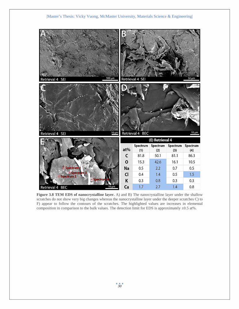
|Master’s Thesis: Vicky Vuong, McMaster University, Materials Science & Engineering|
30
Figure 3.8 TEM EDS of nanocrystalline layer. A) and B) The nanocrystalline layer under the shallow scratches do not show very big changes whereas the nanocrystalline layer under the deeper scratches C) to F) appear to follow the contours of the scratches. The highlighted values are increases in elemental composition in comparison to the bulk values. The detection limit for EDS is approximately ±0.5 at%.

|Master’s Thesis: Vicky Vuong, McMaster University, Materials Science & Engineering|
31
CHAPTER 4 Results and Discussion: Subsurface and Cross-sectional Characterization Subsurface and Cross Sectional Characterization
Using focused ion beam, a sample can be prepared to facilitate observation of the cross-sectional subsurface microstructure at the nanoscale in the TEM. The areas of interest were chosen over scratches (e.g. shallow scratches due to manufacturing on the references and deeper scratches likely due to wear, on the retrievals, Fig. 2.2) to compare differences in subsurface microstructure between manufacturing-induced wear and in vivo wear. The preparation of electron-transparent samples also allows for high resolution analysis of the nanoscale features such as the nanograins in the hard phases and the nanocrystalline layer.
4.1 Hard Phases Analysis of the hard phases in the TEM revealed results similar to those obtained using the SEM. The TEM micrograph in Figure 4.1 shows that the hard phase was several microns deep and had a multiphasic nanocrystalline microstructure. EDS elemental mapping of the hard phase in Retrieval 2 (Fig. 4.1) showed an enrichment of Cr and Mo and a depletion of Co in the area of the hard phase, similar to the EDS line-scan in the SEM (Fig. 3.3) and AES data. Furthermore, there were clear heterogeneous phases within the hard phase containing an enrichment of Co (Fig. 4.1D), which was also shown in the SEM EDS line-scan.
Point spectra EDS analysis of the hard phase revealed what appears to be particulates suspended in the hard phase with varying compositions of Cr, Mo, Co (Fig. 4.2A, B). These results are congruent with the composition of carbides which contain M23C6-type (M=Cr, Mo, Co) and M6C-type phases. The multiphasic nanocrystalline structure of hard phases in Retrieval 2 are characteristic of a cast CoCrMo alloy material. Variable from the hard phase in Retrieval 2, elemental analysis of the Retrieval 3 TEM sample revealed that the hard phase had similar levels of Cr to the bulk material, a slight enrichment in C, a slight depletion of Co, enrichment in Si and large enrichments of Mo (Fig. 4.2C). These results are in agreement with the SEM EDS line-scan of the hard phase mentioned previously (Fig. 3.3F).
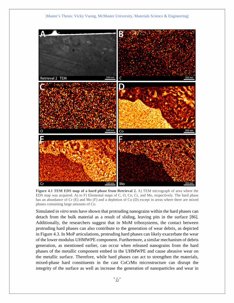
|Master’s Thesis: Vicky Vuong, McMaster University, Materials Science & Engineering|
32
Figure 4.1 TEM EDS map of a hard phase from Retrieval 2. A) TEM micrograph of area where the EDS map was acquired. A) to F) Elemental maps of C, O, Co, Cr, and Mo, respectively. The hard phase has an abundance of Cr (E) and Mo (F) and a depletion of Co (D) except in areas where there are mixed phases containing large amounts of Co.
Simulated in vitro tests have shown that protruding nanograins within the hard phases can detach from the bulk material as a result of sliding, leaving pits in the surface [86]. Additionally, the researchers suggest that in MoM tribosystems, the contact between protruding hard phases can also contribute to the generation of wear debris, as depicted in Figure 4.3. In MoP articulations, protruding hard phases can likely exacerbate the wear of the lower modulus UHMWPE component. Furthermore, a similar mechanism of debris generation, as mentioned earlier, can occur when released nanograins from the hard phases of the metallic component embed in the UHMWPE and cause abrasive wear on the metallic surface. Therefore, while hard phases can act to strengthen the materials, mixed-phase hard constituents in the cast CoCrMo microstructure can disrupt the integrity of the surface as well as increase the generation of nanoparticles and wear in
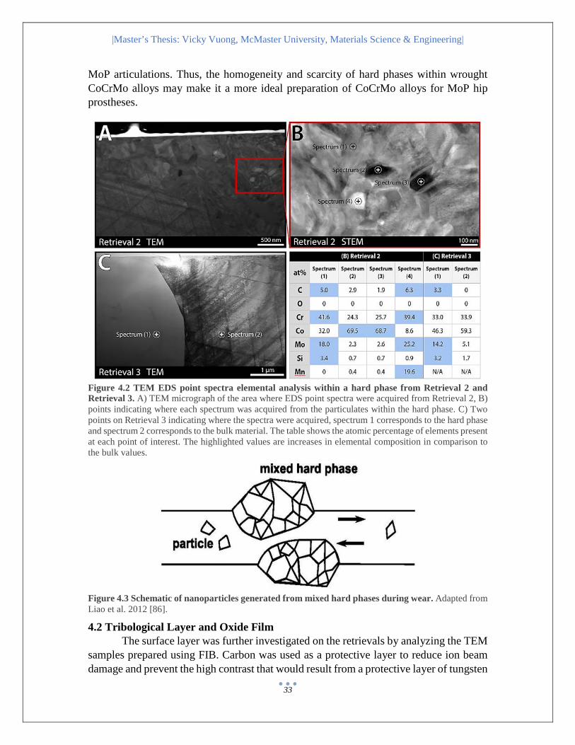
|Master’s Thesis: Vicky Vuong, McMaster University, Materials Science & Engineering|
33
MoP articulations. Thus, the homogeneity and scarcity of hard phases within wrought CoCrMo alloys may make it a more ideal preparation of CoCrMo alloys for MoP hip prostheses.
Figure 4.2 TEM EDS point spectra elemental analysis within a hard phase from Retrieval 2 and Retrieval 3. A) TEM micrograph of the area where EDS point spectra were acquired from Retrieval 2, B) points indicating where each spectrum was acquired from the particulates within the hard phase. C) Two points on Retrieval 3 indicating where the spectra were acquired, spectrum 1 corresponds to the hard phase and spectrum 2 corresponds to the bulk material. The table shows the atomic percentage of elements present at each point of interest. The highlighted values are increases in elemental composition in comparison to the bulk values.
Figure 4.3 Schematic of nanoparticles generated from mixed hard phases during wear. Adapted from Liao et al. 2012 [86].
4.2 Tribological Layer and Oxide Film The surface layer was further investigated on the retrievals by analyzing the TEM
samples prepared using FIB. Carbon was used as a protective layer to reduce ion beam damage and prevent the high contrast that would result from a protective layer of tungsten

|Master’s Thesis: Vicky Vuong, McMaster University, Materials Science & Engineering|
34
or gold. These issues would have otherwise impeded the observation of the tribological layer. Furthermore, the use of a carbon protective layer was justified by the assumption that carbon from the tribological layer could be differentiated from the carbon deposited by the FIB. From the TEM cross-sectional observation of the surface, a thin residual layer was observed above the bulk material (Fig. 4.4A and B, arrows) and was between 10 to 50 nm in thickness. The observation of the layer was most pronounced on the surface of
Figure 4.4 TEM EDS point spectra elemental analysis through the tribological layer and base metal on Retrieval 3. A) and B) Points at which EDS spectrum was acquired. Arrows point to areas where a residual layer is visible above the bulk material. The atomic composition of elements is presented in the table below. Calcium was detected at points above the surface of the bulk material (amounts are highlighted on the table in blue). C) and D) are two examples of elemental spectra where in C) there is no Ca peak and in D there is are two evident Ca peaks at approximately 3.7 keV and 4.0 keV.
Retrieval 3, perhaps due to the fact that the surface of this sample was the least disturbed through cleaning and sample preparation procedures (it was typically the last sample to be prepared). TEM EDS analysis showed that the residual layer contained large amounts of C, O, and smaller amounts of Si, and Ca. The layer observed was less than 100 nm in thickness. The presence of Ca appeared to always be coupled with greater
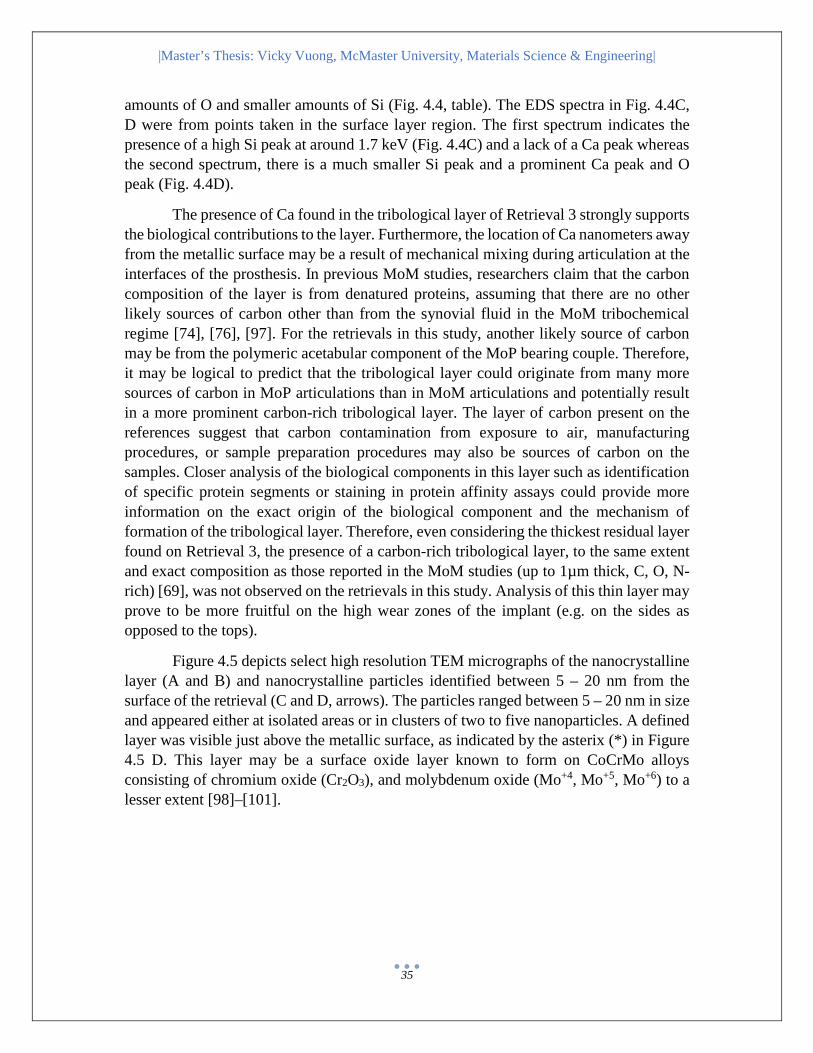
|Master’s Thesis: Vicky Vuong, McMaster University, Materials Science & Engineering|
35
amounts of O and smaller amounts of Si (Fig. 4.4, table). The EDS spectra in Fig. 4.4C, D were from points taken in the surface layer region. The first spectrum indicates the presence of a high Si peak at around 1.7 keV (Fig. 4.4C) and a lack of a Ca peak whereas the second spectrum, there is a much smaller Si peak and a prominent Ca peak and O peak (Fig. 4.4D).
The presence of Ca found in the tribological layer of Retrieval 3 strongly supports the biological contributions to the layer. Furthermore, the location of Ca nanometers away from the metallic surface may be a result of mechanical mixing during articulation at the interfaces of the prosthesis. In previous MoM studies, researchers claim that the carbon composition of the layer is from denatured proteins, assuming that there are no other likely sources of carbon other than from the synovial fluid in the MoM tribochemical regime [74], [76], [97]. For the retrievals in this study, another likely source of carbon may be from the polymeric acetabular component of the MoP bearing couple. Therefore, it may be logical to predict that the tribological layer could originate from many more sources of carbon in MoP articulations than in MoM articulations and potentially result in a more prominent carbon-rich tribological layer. The layer of carbon present on the references suggest that carbon contamination from exposure to air, manufacturing procedures, or sample preparation procedures may also be sources of carbon on the samples. Closer analysis of the biological components in this layer such as identification of specific protein segments or staining in protein affinity assays could provide more information on the exact origin of the biological component and the mechanism of formation of the tribological layer. Therefore, even considering the thickest residual layer found on Retrieval 3, the presence of a carbon-rich tribological layer, to the same extent and exact composition as those reported in the MoM studies (up to 1µm thick, C, O, N-rich) [69], was not observed on the retrievals in this study. Analysis of this thin layer may prove to be more fruitful on the high wear zones of the implant (e.g. on the sides as opposed to the tops).
Figure 4.5 depicts select high resolution TEM micrographs of the nanocrystalline layer (A and B) and nanocrystalline particles identified between 5 – 20 nm from the surface of the retrieval (C and D, arrows). The particles ranged between 5 – 20 nm in size and appeared either at isolated areas or in clusters of two to five nanoparticles. A defined layer was visible just above the metallic surface, as indicated by the asterix (*) in Figure 4.5 D. This layer may be a surface oxide layer known to form on CoCrMo alloys consisting of chromium oxide (Cr2O3), and molybdenum oxide (Mo+4, Mo+5, Mo+6) to a lesser extent [98]–[101].

|Master’s Thesis: Vicky Vuong, McMaster University, Materials Science & Engineering|
36
Figure 4.5 HRTEM micrographs from Retrieval 3. A) and B) HRTEM micrographs of the nanocrystalline layer, showing the alignment of nanocrystals near the surface. C) and D) are HRTEM micrographs of the residual layer above the bulk material. Arrows point to areas where a nanocrystalline particle is found above the bulk material. The asterix (*) in D) indicates the potential oxide layer directly above the metallic surface of the sample. To identify the chemical composition of these nanocrystalline particles, EELS analysis was performed and the results are presented in Figure 4.6. The EELS elemental maps showed that the nanocrystalline particles are enriched in O, Fe, and F, suggesting the presence of iron oxides. The O and Cr map also support the presence of a chromium oxide layer above the metallic surface (Figure 4.6B, asterix) and a slight depletion of Co in that oxide layer. To further distinguish between the possible forms of iron oxides, the spacing between the lattice fringes were measured in the HRTEM images. Of the 15 particles examined, nearly half of the atomic spacings corresponded well to either magnetite (Fe3O4) or maghemite (γ-Fe2O3). The other particles either yielded insufficient points in the FFT or resulted in d-spacings that overlapped with many iron oxides. The Fe and O edges obtained in the EELS spectrum were inconclusive, more data is required to precisely identify the identity of the oxides found above the surface layer [102].
Researchers suggest that in addition to wear (or as a result of wear), corrosion of the implant materials or wear particles may also contribute to the dissolution of metal ions into the surrounding tissue and blood stream [75], [98], [103]. The passive oxide layer on CoCrMo alloys is spontaneously formed from exposure to air. It provides increased corrosion and fretting resistance to the base alloy, however, it can be compromised during wear and depassivation may lead to dissolution of the underlying base alloy [104]. It has been established that Co is the major species dominating active

|Master’s Thesis: Vicky Vuong, McMaster University, Materials Science & Engineering|
37
dissolution in CoCrMo alloys, which may account for the slight depletion of Co in the oxide layer. The loss of integrity in the oxide layer during in vivo articulation may also facilitate the dissolution of Fe from the base CoCrMo alloy (Arcam ASTM F75 contains 0.2% Fe). Alternatively, the Fe can originate from the surrounding synovial fluid as it has been shown that patients with rheumatoid arthritis (inflammation of joint lining) have higher synovial fluid levels of free Fe ions [105]. Regardless of the origin, many forms of iron oxides (like other corrosion by-products) are cytotoxic and can cause adverse cellular responses in the periprosthetic tissues, contributing to the failure of the implant [105], [106].
Figure 4.6 EELS mapping on the nanoparticles. A) TEM micrograph of area selected for EELS analysis. B) to F) EELS elemental maps for O, Co, Cr, Fe, and F, respectively. The maps show that the particles are enriched in Fe, O, and F. The asterix (*) in B indicates oxide layer above the metallic surface.

|Master’s Thesis: Vicky Vuong, McMaster University, Materials Science & Engineering|
38
4.3 Nanocrystalline Layer TEM of the FIB cross-sectional preparations revealed a subsurface nanocrystalline microstructure across all of the samples (Fig. 4.7 and Fig. 4.9). The subsurface microstructure was particularly evident using bright-field STEM at higher magnifications. The nanocrystalline layer on wrought Reference 1 was approximately 200 nm in thickness (Fig. 4.7B). The nanocrystalline layer was quite variable on Reference 2, between 20 nm to 100 nm (Fig. 4.9B). The nanocrystalline layer on Retrieval 1 ranged from 40 to 100 nm in thickness; approximately 350 nm in Retrieval 2; and 100 nm in Retrieval 3 (Fig. 4.7 and Fig. 4.9). Additionally, STEM EDS mapping of the nanocrystalline layer showed that the layer had the same elemental composition as the bulk alloy material below (Fig. 4.10).
Figure 4.7 TEM micrographs of the subsurface microstructure in the wrought samples. A) and B) show TEM low magnification, overviews of the subsurface microstructure. B) and D) show STEM micrographs of the subsurface nanocrystalline layer. The arrows show the maximum thickness of the nanocrystalline layer in the micrograph.
Overall, the thicknesses of the nanocrystalline layer ranged from 20 to 350 nm, where the lower end of the range corresponded to the layer found in the puck reference sample as well as in Retrieval 1. The variable thicknesses of the nanocrystalline layer may be attributed to the degree of manufacturing, for example, the femoral head wrought Reference 1 sample had a more prominent nanocrystalline layer compared to the puck cast Reference 2 sample which had a nanocrystalline layer that was more variable in thickness. Logically, more in vivo articulations can also result in the thickening of this nanocrystalline layer [107], [108]. This may help to account for the thickest layer found in Retrieval 2 as it was in service for 15 years. Lastly, the variability of thicknesses may

|Master’s Thesis: Vicky Vuong, McMaster University, Materials Science & Engineering|
39
be site-specific, with thicker nanocrystalline layers developing in areas that have undergone more articulations, which would explain the inconsistent thickness of the nanocrystalline layers seen at lower magnification overviews of the FIB samples.
The presence of a nanocrystalline layer (up to 500 nm in thickness) has been reported in the subsurface microstructure of MoM retrievals on the metallic femoral head component and the acetabular cups [107]. The conclusions drawn from multiple studies suggest that plastic deformation produced during the multidirectional, repetitive sliding leads to mechanical milling and dynamic recrystallization at the immediate subsurface layer. The researchers suggest that plastic deformation during mechanical polishing in the manufacturing process was insufficient to induce nanocrystal formation, however references were not investigated. Other studies suggest that cyclic shear stress in low stacking fault materials (i.e. CoCrMo alloys) generate localized plastic deformation along the discrete sliding planes resulting in dislocations, twins, stack faults, hardening and increased mechanical stability [97], [107], [108]. Consequently, the formation of nanocrystals is attributed to the large strain and repetitive loading [101], [109]. Simulated in vitro studies showed abrasion wear marks are caused by the rotation, sliding, and ultimate removal of the nanocrystals in the nanocrystalline layer. This detachment of material (i.e. nanocrystals) from the nanocrystalline layer is a source of globular-shaped (Cr, up to 90 nm) wear debris, whereas needle-shaped (Co and Cr, 40 – 120 nm) wear debris is generated by fractured Ɛ-martensite [97], [107], [110], [111]. Figure 4.8 is a schematic showing the delineation of layers formed in the worn contact area of metal-on-metal prostheses. Zone 1 corresponds to the bulk alloy material, Zone 2 refers to the plastically deformed layer, and Zone 3 is the mechanical mixed layer containing the nanocrystalline mixed layer and the tribochemical reaction layer (Fig. 4.8).
Figure 4.8 Cross-sectional schematic of different regions beneath the worn surface of a metal-on-metal sliding contact. Figure adapted from Hutchings, 1992 [109].

|Master’s Thesis: Vicky Vuong, McMaster University, Materials Science & Engineering|
40
Contrary to previous reports claiming the nanocrystalline layer is a result of in vivo dynamic recrystallization [97], [112], TEM revealed that the nanocrystalline layer was present on both the reference and retrieval samples. This suggests that the nanocrystalline layer is present prior to implantation and may very likely be a result of mechanical polishing during the manufacturing processes. However, the variable thickness across the samples suggest that in vivo wear (i.e. dynamic recrystallization in vivo) and site-dependent thicknesses (e.g. high contact stress zones may have thicker
Figure 4.9 TEM micrographs of the subsurface microstructure in the cast samples. A), C), E) show TEM low magnification, overviews of the subsurface microstructure. B), D), F) show STEM micrographs of the subsurface nanocrystalline layer. The arrows show the maximum thickness of the nanocrystalline layer in the micrograph.
nanocrystalline layers) cannot simply be dismissed. Researchers in an electrochemical investigation, hypothesize that the passive oxide film can act as a barrier to tribocorrosion, favoring the process of dynamic recrystallization. This mechanism supports the protective role of passive oxide films and helps to explain the varying thicknesses of the

|Master’s Thesis: Vicky Vuong, McMaster University, Materials Science & Engineering|
41
nanocrystalline layer [109]. Previous studies have not compared the nanocrystalline layer of the retrievals to unused reference implants or the in vitro simulated samples to uncycled references. This study stresses the important information provided by the references in regards to manufacturing defects present prior to implantation.
Figure 4.10 STEM EDS map of nanocrystalline layer. A) to B) The elemental EDS maps show no distinction of elemental variation between the nanocrystalline layer and the base alloy material.
As mentioned previously, the FIB preparations were taken over observable scratches on the surface which allowed for observation of the cross-sectional subsurface microstructure beneath the scratches. In Figure 4.11, the shallower scratches in Reference 1 (A) and Retrieval 1 (B) showed little change in the subsurface nanocrystalline layer directly beneath the scratches. However, in the deeper scratches observed on Retrieval 2 (Fig. 4.11C, D) and Retrieval 3 (Fig. 4.11E, F), the nanocrystalline layer appeared to dip lower, following the contours formed by the scratches.

|Master’s Thesis: Vicky Vuong, McMaster University, Materials Science & Engineering|
42
Figure 4.11 STEM micrographs of the subsurface microstructure under scratches on the surface. A) and B) The nanocrystalline layer under the shallow scratches do not show very big changes whereas the nanocrystalline layer under the deeper scratches C) to F) appear to follow the contours of the scratches.
The cross-section of a scratch can provide important information, such as the microstructure of the material removed from the surface during the generation of wear debris as a result of scratch formation. In the deeper scratches, the nanocrystalline layer appears to dip below the relatively flat surface, however, the thickness of the layer does not appear to change significantly. The trough in the material is likely formed by an abrasive force removing material, in the form of the nanocrystals, from the surface thereby generating nanoscale wear particles. The consistent thickness of the layer under the trough may suggest that the plastic deformation imposed on the surface to form the deeper scratches is sufficient to result in dynamic recrystallization of the subsurface microstructure directly beneath the scratch [97]. Consequently, wear debris generated from the removal of hard phases from the bulk material are M23C6-type (M = Cr, Mo, Co) and M6C-type phases whereas the wear debris generated from the bulk material likely
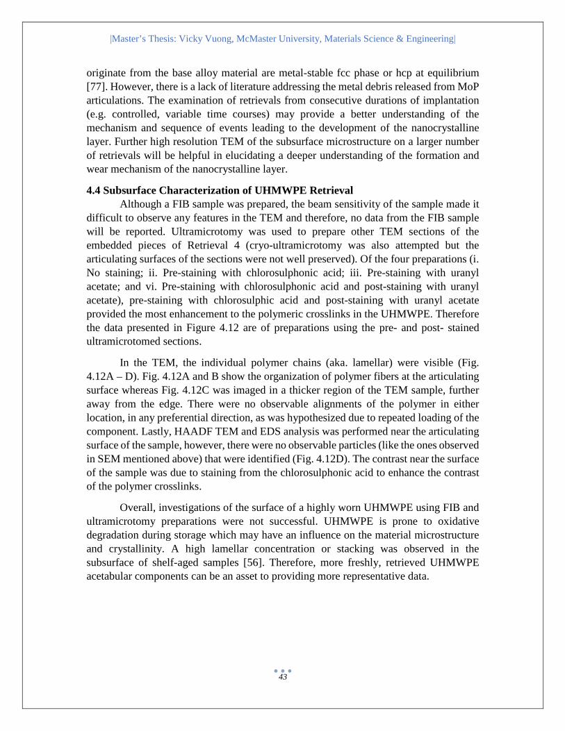
|Master’s Thesis: Vicky Vuong, McMaster University, Materials Science & Engineering|
43
originate from the base alloy material are metal-stable fcc phase or hcp at equilibrium [77]. However, there is a lack of literature addressing the metal debris released from MoP articulations. The examination of retrievals from consecutive durations of implantation (e.g. controlled, variable time courses) may provide a better understanding of the mechanism and sequence of events leading to the development of the nanocrystalline layer. Further high resolution TEM of the subsurface microstructure on a larger number of retrievals will be helpful in elucidating a deeper understanding of the formation and wear mechanism of the nanocrystalline layer.
4.4 Subsurface Characterization of UHMWPE Retrieval Although a FIB sample was prepared, the beam sensitivity of the sample made it
difficult to observe any features in the TEM and therefore, no data from the FIB sample will be reported. Ultramicrotomy was used to prepare other TEM sections of the embedded pieces of Retrieval 4 (cryo-ultramicrotomy was also attempted but the articulating surfaces of the sections were not well preserved). Of the four preparations (i. No staining; ii. Pre-staining with chlorosulphonic acid; iii. Pre-staining with uranyl acetate; and vi. Pre-staining with chlorosulphonic acid and post-staining with uranyl acetate), pre-staining with chlorosulphic acid and post-staining with uranyl acetate provided the most enhancement to the polymeric crosslinks in the UHMWPE. Therefore the data presented in Figure 4.12 are of preparations using the pre- and post- stained ultramicrotomed sections.
In the TEM, the individual polymer chains (aka. lamellar) were visible (Fig. 4.12A – D). Fig. 4.12A and B show the organization of polymer fibers at the articulating surface whereas Fig. 4.12C was imaged in a thicker region of the TEM sample, further away from the edge. There were no observable alignments of the polymer in either location, in any preferential direction, as was hypothesized due to repeated loading of the component. Lastly, HAADF TEM and EDS analysis was performed near the articulating surface of the sample, however, there were no observable particles (like the ones observed in SEM mentioned above) that were identified (Fig. 4.12D). The contrast near the surface of the sample was due to staining from the chlorosulphonic acid to enhance the contrast of the polymer crosslinks.
Overall, investigations of the surface of a highly worn UHMWPE using FIB and ultramicrotomy preparations were not successful. UHMWPE is prone to oxidative degradation during storage which may have an influence on the material microstructure and crystallinity. A high lamellar concentration or stacking was observed in the subsurface of shelf-aged samples [56]. Therefore, more freshly, retrieved UHMWPE acetabular components can be an asset to providing more representative data.
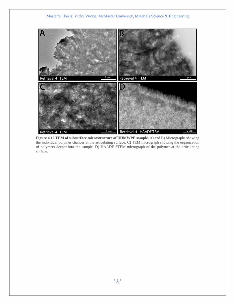
|Master’s Thesis: Vicky Vuong, McMaster University, Materials Science & Engineering|
44
Figure 4.12 TEM of subsurface microstructure of UHMWPE sample. A) and B) Micrographs showing the individual polymer chances at the articulating surface. C) TEM micrograph showing the organization of polymers deeper into the sample. D) HAADF STEM micrograph of the polymer at the articulating surface.

|Master’s Thesis: Vicky Vuong, McMaster University, Materials Science & Engineering|
45
CHAPTER 5 Conclusions In response to the adverse biological reactions to prosthesis wear debris, a wealth of research using advanced electron microscopy has been performed in MoM articulations, however, congruent experiments have not been equally explored in MoP articulations. This study aims to characterize prevalent structures found on the surface and subsurface of MoP retrievals and compare them to references and previous MoM results to elucidate the influence of such structures on wear. The data reveals that contrary to what has been previously reported in MoM studies, although the extent of wear on the retrieval samples is, logically, more severe in comparison to the reference samples, imperfections are not exclusive to retrievals and may (at least partially) be a by-product of manufacturing. Moreover, the microstructures observed on the MoP retrievals contain both similar and dissimilar characteristics to MoM retrievals, thereby validating that the results on MoM components cannot be entirely extrapolated to MoP prostheses. The following section will summarize the major findings, identify limitations of the experiments and propose areas for future work.
5.1 Summary of Major Findings The microscopy techniques used resulted in agreeable data (Table 5.1) Scratches present on references due to manufacturing process; wear on retrievals
due to manufacturing process and in vivo articulation Cast samples contain multiphasic MxCy (M=Cr, Mo) hard phases that may
exacerbate abrasive wear Tribological layer rich in C, O is present on surface of retrievals, but the
thickness is not comparable to tribological layers reported in MoM studies Nanocrystalline subsurface layer present in references and retrievals; scratches
and in vivo wear may influence the thickness of this layer Retrieved surface of UHMWPE is highly worn and contains presence of organic
elements
Table 5.1 summarizes the results across all microscopy techniques used to analyze the hard phases and the tribological layers in the samples.
Firstly, the predominant wear mode on the surface of the samples is abrasive wear. The scratches on the references samples are fewer, more uniform, and likely a result of mechanical polishing from the proprietary manufacturing process. The scratches on the retrievals are representative of both in vivo wear mechanisms and manufacturing. Furthermore, the duration of implantation is correlated with the abundance and depth of the scratches.
Hard phases found on the cast samples contain an enrichment of Cr, Mo, C and most of the time, a depletion of Co. The hard phases in Retrieval 2 and 3 are multiphasic, containing suspensions of Co-rich particulates. The presence of hard phases can improve
|Master’s Thesis: Vicky Vuong, McMaster University, Materials Science & Engineering|
46
the strength of the material but they can also embrittle the alloy, exacerbate wear of the UHMWPE surface and if torn off, contribute to third-body abrasive wear. Wrought CoCrMo may be the preferable material for MoP articulations since repeated cycles of heating and cooling in its preparation lead to lower amounts of carbides formation (of which are typically monophasic).
A residual/tribological layer was observed on the surface of the retrieval samples (and not the reference samples) using SEM, AES and TEM. The tribological layer was less evident in Retrieval 1 compared to Retrievals 2 and 3, which may suggest that longer in vivo service duration (i.e. more than 2 years) is required for the development of a tribological layer. The results from AES point spectra show regions corresponding to a higher composition (at%) of C, O, or Si (darker patches) and other regions corresponding to a higher composition of Cr, Mo, or Co (brighter tribological patches). AES depth profiling did not reveal a tribological layer on the MoP retrievals of the same thickness as those reported in MoM retrieval studies. The baseline carbon layer (~10 nm) on the reference samples suggest that the presence of carbon can be contamination as a result of the manufacturing process, sample preparation or simply, exposure to air.
An oxide layer, likely containing Cr2O3, is also detected on the surface of Retrieval 3 during HRTEM imaging and EELS mapping. Furthermore, HRTEM and EELS have revealed nanocrystalline particles above the surface of Retrieval 3. The speculated identity of these nanocrystals have been narrowed down to magnetite (Fe3O4) and/or maghemite (γ-Fe2O3), however further analysis must be performed to characterize the chemical and crystal structure. Despite the report of nanocrystalline particles containing Co and Cr in MoM studies, no such particles were observed in these samples.
A nanocrystalline layer was observed beneath the surface, across all samples. The height of the nanocrystalline layer was variable within some samples and overall, ranged from between 20 to 350 nm. The presence of the layer in the reference samples suggests that contrary to the in vivo dynamic recrystallization mechanism proposed by previous MoM studies, the nanocrystalline layer can be a produce of mechanical polishing during production. Nonetheless, a closer investigation of the microstructure beneath the scratches reveals that deeper scratches (not shallow ones) result in a change in the subsurface nanocrystalline layer, leading to a dip that follows the contours of the scratch. This suggests that although the nanocrystalline layer is present prior to implantation, in vivo wear may be sufficient to induce changes to the subsurface microstructure.
Lastly, in the UHMWPE sample, the surface was largely flaky and highly worn. SEM EDS found the presence of organic elements including Na, Cl, K, and Ca suggesting a biochemical interaction at the surface of the acetabular component. TEM (BF, DF, and HAADF) revealed the organization of polymer chains but unfortunately no alignment of polymer chains or the presence of the organic compounds were found in these preparations.

|Master’s Thesis: Vicky Vuong, McMaster University, Materials Science & Engineering|
47
Table 5.1 Summary of results on the carbides/hard phases, tribological layer, and the UHMWPE sample. ‘D’ represents the darker areas in the tribological layer, ‘B’ represents the lighter areas in the tribological layer. ‘+’ represents an increase in comparison to the reference samples or the bulk material, correspondingly and ‘–‘ represents a decrease in comparison to the reference samples or the bulk material.
5.2 Limitations The major limitations of this study pertain to the scarcity of MoP THA retrievals, the complexity of biological contributions, and the challenge of quantifying the elemental composition of such small and highly variable structures (e.g. nanometer-thick tribological layer).
Although the analysis of retrieval samples greatly improves the value of knowledge generated in these experiments, it also presents many limitations. Firstly, the rarity of retrieval samples limit the available sample size included in this study. A greater sample size of retrievals can increase the generalizability of the results to MoP prostheses. Similarly, it was challenging to acquire appropriate references (e.g. Reference 2 was a cast puck as opposed to a femoral head component) to the retrieval samples since the production of prostheses is an undisclosed, proprietary process. In addition, a more
Microscopy Techniques
Features Examined Sample SEM EDS AES Point
Spectrum AES DP TEM EDS EELS
Carbides/Hard Phases
Reference 2 ++Cr, +Mo, --Co
+Cr, +Mo, +C, +O, --Co
+Cr, +C, --Co
- -
Retrieval 2
+Cr, ++Mo,
+C, +Si, --Co
+Cr, ++Mo,
+C, +Si, -Co
-
EDS map: ++Cr, +Mo,
-Co, (+Co suspended particles)
-
Retrieval 3
+Cr, ++Mo,
+Si, -Co
++Mo, +C, +O, -Co
-
EDS Point: +Mo, +C, +Si -Co
-
Tribological Layer
Retrieval 1 - D: +C B: +Cr ~15 nm - -
Retrieval 2 -
D: +O, +Si
B: +Cr, +Mo
~17nm - +O, +Fe, +F
Retrieval 3 - D: +C B: +Co ~ 30nm
+O, +Ca, +Si
-

|Master’s Thesis: Vicky Vuong, McMaster University, Materials Science & Engineering|
48
correlative analysis can be attained with the access to retrieval samples containing both the UHMWPE acetabular cup and complimentary CoCrMo femoral head. The contact areas on both surfaces can be compared to further investigate the tribological conditions in the system. Moreover, The UHMWPE sample examined in this study was largely damaged and had been removed for a long period of time and therefore, is likely not representative of an in vivo acetabular component.
Moreover, the unique positioning of the prosthesis in the patient and subsequently, the inconsistency of the high contact zones, prevent analysis of the most highly worn areas of interest. Also, the retrieval samples require thorough sterilization with the use of stringent detergents that remove and dissolve the majority of organic matter which can destroy the integrity of structures that are assumed to be of biological origin (e.g. synovial fluid contributions to the tribological layer). An amendment to the experimental procedure may include analysis of the samples prior to the harsh cleaning conditions as well as after, to preserve the possibility of disturbing certain features on the surface. If such conditions can be explored, given adequate resources, cryoSEM/TEM can be used to investigate the tribological layer [113]. This may also allow for the probing of proteins (e.g. using negative stains for TEM samples) on the surface of the implants, which naturally contribute to the tribology of the MoP system.
Another limitation in this study is the lack of statistically quantitative data, the majority of results reported are qualitative observations. The small size of the TEM samples prepared by FIB, further limits the possibility for statistical evaluation. However, with the access to more FIB preparations, the thickness of the nanocrystalline layer can be measured and perhaps correlated to the presence of scratches or the integrity of the passive oxide layer. On the other hand, although the surface sensitivity of AES makes it an ideal technique for the identification of elements in the thin surface layer above the implant surface, the presence of carbon can result in confounding results. The large composition of carbon can hinder the identification (i.e. mask the overlapping elemental peaks in the generated AES spectra) of other trace elements which may be present in the tribological layer such as Ca or Si. Moreover, exposure of the samples to air can result in a surface layer of carbon several nanometers in thickness (as seen on the references), consequently, it may be difficult to differentiate between carbon contamination and carbon that is truly present on the surface of the samples. Due to the influence of carbon, the comparison of elemental composition between samples (e.g. retrievals to references) may not be reliable since the relative composition will vary depending on the amount of carbon present in the sample. However, the relative comparisons within the same sample, since they contain equivalent amounts of carbon contamination may still be reasonable. In addition, the complimentary data obtained from the cross-sectional TEM samples are able to provide additional information on the composition of the tribological layer. More precise quantification of data can be achieved by the preparation of appropriate standards.

|Master’s Thesis: Vicky Vuong, McMaster University, Materials Science & Engineering|
49
5.3 Future Directions Firstly, to obtain a more exhaustive analysis of the samples at hand, further work on HRTEM and EELS can be performed on additional FIB-prepared TEM samples. If possible, the preparation of more FIB samples (and TEM and EELS analysis) from Retrieval 3 can be used to identify the exact chemical composition and crystal structure of the iron oxide nanoparticles identified above the surface. Also, it may be informative to identify these iron oxides in other retrieval samples to limit the possibility that the iron oxides are an anomaly from contamination. Additionally, it may be worthwhile to investigate the integrity of the chromium oxide surface layer, its influence on the dissolution of ions from the base alloy and consequently the role corrosion plays in the system (this was outside the scope of the current research). The effect of scratches on the surface oxide layer was not clearly observable in the results of this study.
To enhance the value of retrieval studies, collaboration with surgeons to obtain more detailed patient-specific information such as implant manufacturer data, implant positioning or synovial fluid ion concentrations would provide a more comprehensive understanding of mechanical and physiological factors that influence the wear of hip prostheses. Additionally, the examination of wear debris generated from corresponding implants will provide complimentary information to determine whether the scratches will produce wear debris that is similar in composition and morphology to the nanocrystalline layer or the hard phases. This requires large scale collaboration – more efficient sample collection procedures during scheduled clinical follow-up visits rather than post implant failure.
To further investigate the previously “assumed” biological contributions to the tribological layer (simply by the presence of carbon), a protein assay or negative stain may be used to probe partial segments of the proteins that likely exist and play a role in the synovial lubrication of the artificial joint. Many studies simply report the enrichment of carbon in the tribological layer, but since the sources of carbon are more plentiful in the MoP system, the precise characterization of the composition may provide insight on the mechanism of formation.
Lastly, since the generation of the scratches, the development of the tribological layer and the formation of the nanocrystalline layer are all potentially dependent on the duration of implantation, it may be interesting to perform a correlative study using samples implanted for different durations of time. Undoubtedly, in vivo physiological conditions are complex and tend to vary greatly between patients, thus, may present additional challenges.
5.4 Conclusions In conclusion, the data obtained each progressive advanced microscopy technique
was coherent, and supportive of the initial hypotheses. The observation of structures, such as scratches and nanocrystalline layers, in the reference and (often to a greater extent) in the retrievals suggest that imperfections produced by the manufacturing process influence the in vivo performance of the prosthesis. The observation of the nanocrystalline layer in
|Master’s Thesis: Vicky Vuong, McMaster University, Materials Science & Engineering|
50
the reference samples (and the retrievals) is a novel, yet fundamental finding that had been over-sighted by previous research on MoM articulations. The pre-existing imperfections in new, unused prostheses may have protective effects but may also exacerbate the in vivo wear of the MoP components. This further emphasizes the importance of examining corresponding references in retrieval as well as in in vitro simulator studies. The differences in the magnitude of microstructures readily observed in MoM and MoP studies, further support that the two tribological systems operate under different in vivo conditions. Which explains how the two articulations can result in the production of different wear rates, wear particles with different size and morphology as well as result in different modes of failure.
The current, fashionable strategy to improving hip prostheses is to increase the strength, hardness and other mechanical properties of the bearing materials. Arguably, as Charnley believed, the clinical success of MoP prostheses may be in the articulation of a hard and soft component in the bearing combination, since it mimics the natural hip joint anatomy. Furthermore, it is interesting that although the metallic component is severely worn during the in vivo service of the prosthesis, failure as a result of metal debris release is secondary to the effects of PE debris. It may be worthwhile to entertain the potential of a lower modulus coating material, similar in mechanical properties to UHMWPE, which generates biocompatible, biodegradable wear debris to prevent catastrophic biological consequences when released.
The ideal artificial hip joint is biocompatible, is customizable (i.e. to patient’s height, weight, and unique joint geometry), can restore function with no limitations to lifestyle and can survive without failure, until the patient expires. This study and future works on MoP prostheses have large implications on the THA procedure because MoP is not only the gold standard for hip prostheses, it also has the most extensive registry of short-term and long-term clinical data to support experimental results. The development of the ideal THA material combination of THA prostheses has not yet been realized, but meticulous investigations of MoP articulations, one of the most proficient prosthesis designs, may reveal the key to longevity of total hip prostheses.
|Master’s Thesis: Vicky Vuong, McMaster University, Materials Science & Engineering|
51
References [1] J. S. Siopack and H. E. Jergesen, “Total hip arthroplasty.,” West. J. Med., vol.
162, pp. 243–249, 1995.
[2] R. Pivec, A. J. Johnson, S. C. Mears, and M. A. Mont, “Hip arthroplasty.,” Lancet, vol. 380, pp. 1768–77, 2012.
[3] P. F. Gomez and J. a Morcuende, “Early Attempts at Hip Arthroplasty: 1700s to 1950s,” Iowa Orthop. J., vol. 25, pp. 25–29, 2005.
[4] W. Wang, Y. Ouyang, and C. K. Poh, “Orthopaedic implant technology: Biomaterials from past to future,” Annals of the Academy of Medicine Singapore, vol. 40. pp. 237–243, 2011.
[5] J. T. A. Mäkelä, M. R. J. Huttu, and R. K. Korhonen, “Structure-function relationships in osteoarthritic human hip joint articular cartilage,” Osteoarthr. Cartil., vol. 20, pp. 1268–1277, 2012.
[6] a S. Greenwald and J. J. O’Connor, “The transmission of load through the human hip joint.,” Journal of biomechanics, vol. 4. pp. 507–528, 1971.
[7] E. M. Tansey and L. a Reynolds, “EARLY DEVELOPMENT OF TOTAL HIP REPLACEMENT,” Transcr. a Witn. Semin. held by Wellcome Trust Cent. Hist. Med. UCL, London, vol. 29, no. March, 2006.
[8] P. T. Burgers and J. van Gijn, “Sir John Charnley and total hip arthroplasty,” Ned. Tijdschr. Geneeskd., vol. 155, p. A3564, 2011.
[9] P. F. Gomez and J. a Morcuende, “A historical and economic perspective on Sir John Charnley, Chas F. Thackray Limited, and the early arthoplasty industry.,” Iowa Orthop. J., vol. 25, pp. 30–37, 2005.
[10] C. Michet, T. Mason, and M. Mazlumzadeh, “Hip joint disease in psoriatic arthritis: risk factors and natural history,” Ann. Rheum. Dis., vol. 64, no. 7, pp. 1068–1070, Jul. 2005.
[11] W. H. Harris, Etiology of osteoarthritis of the hip. 1986, pp. 20–33.
[12] A. C. Gelber, M. C. Hochberg, L. A. Mead, N. Y. Wang, F. M. Wigley, and M. J. Klag, “Joint injury in young adults and risk for subsequent knee and hip osteoarthritis,” Ann. Intern. Med., vol. 133, pp. 321–328+I16, 2000.
[13] M. J. Chmell, R. D. Scott, W. H. Thomas, and C. B. Sledge, “Total hip arthroplasty with cement for juvenile rheumatoid arthritis. Results at a minimum
|Master’s Thesis: Vicky Vuong, McMaster University, Materials Science & Engineering|
52
of ten years in patients less than thirty years old.,” J. Bone Joint Surg. Am., vol. 79, pp. 44–52, 1997.
[14] T. Odent, P. Journeau, A.-M. Prieur, P. Touzet, J.-C. Pouliquen, and C. Glorion, “Cementless hip arthroplasty in juvenile idiopathic arthritis.,” J. Pediatr. Orthop., vol. 25, pp. 465–70, 2005.
[15] V. S. Pai, D. Ardern, and N. Wilson, “Fractured neck of femur in the mobile independent elderly patient: should we treat with total hip replacement?,” J. Orthop. Surg. (Hong Kong), vol. 11, pp. 123–128, 2003.
[16] N. K. Ternovoĭ, A. V Samokhin, and K. A. Grebennikov, “Total hip replacement in elderly and senile patients with initial femur neck fractures,” Lik. Sprava, pp. 59–61, 2003.
[17] A. Ranawat, J. Zelken, D. Helfet, and R. Buly, “Total Hip Arthroplasty for Posttraumatic Arthritis after Acetabular Fracture,” J. Arthroplasty, vol. 24, pp. 759–767, 2009.
[18] S. Gencur, “Failure micromechanisms during uniaxial tensile fracture of conventional and highly crosslinked ultra-high molecular weight polyethylenes used in total joint replacements,” Biomaterials, vol. 24, no. 22, pp. 3947–3954, Oct. 2003.
[19] G. Hartofilakidis and T. Karachalios, “Total hip arthroplasty for congenital hip disease.,” J. Bone Joint Surg. Am., vol. 86-A, pp. 242–250, 2004.
[20] B. a Rogers, S. Garbedian, R. a Kuchinad, D. Backstein, O. Safir, and A. E. Gross, “Total hip arthroplasty for adult hip dysplasia.,” J. Bone Joint Surg. Am., vol. 94, pp. 1809–21, 2012.
[21] C. I. for H. Information, “Hip and Knee Replacements in Canada : Canadian Joint Replacement Registry 2013 Annual Report,” 2013.
[22] N. Wishart, R. Beaumont, E. Young, V. Mccormack, and M. Swanson, “National Joint Registry: 11th Annual Report,” no. December 2013, 2014.
[23] R. W. Crawford and D. W. Murray, “Total hip replacement: indications for surgery and risk factors for failure.,” Ann. Rheum. Dis., vol. 56, pp. 455–457, 1997.
[24] G. R. Kurtz S.M., Roder C., Lau E., Ong K., Widmer M., Maravic M., Gomez-Barrena E., Pina M.F., Manno V., “International Survey of Primary and Revision Total Hip Replacement,” 56th Annu. Meet. Orthop. Res. Soc., vol. Paper No ., no. 365, p. 2007, 2007.

|Master’s Thesis: Vicky Vuong, McMaster University, Materials Science & Engineering|
53
[25] S. M. Kurtz, K. L. Ong, E. Lau, and K. J. Bozic, “Impact of the Economic Downturn on Total Joint Replacement Demand in the United States Updated Projections to 2021,” J. Bone Joint Surg. Am., vol. 96, no. 8, pp. 624–630, 2014.
[26] C. Eingartner, “Current Trends in Total Hip Arthrplasty,” Traumatologia, vol. 9, no. 6, pp. 8–14, 2007.
[27] J. R. C. Callaghan J.J., Forest E.E., Sporer S.M., Goetz D.D., “Total Hip Arthroplasty in the Young Adult.” pp. 257–262, 1997.
[28] K. G. Makridis, O. Obakponovwe, P. Bobak, P. V Giannoudis, and F. Ortho, “Total Hip Arthroplasty after Acetabular Fracture : Incidence of Complications , Reoperation Rates and Functional Outcomes : Evidence Today,” J. Arthroplasty, vol. 29, no. 10, pp. 1983–1990, 2014.
[29] T. C. B. Pollard, R. P. Baker, S. J. Eastaugh-Waring, and G. C. Bannister, “Treatment of the young active patient with osteoarthritis of the hip. A five- to seven-year comparison of hybrid total hip arthroplasty and metal-on-metal resurfacing.,” J. Bone Joint Surg. Br., vol. 88, pp. 592–600, 2006.
[30] N. C. L. Kamath A.T, Sheth N.P., Hosalkar H.H., Babtunde O.M., Lee G.C., “Modern Total Hip Arthroplasty in Patients Younger than 21 Years,” J. Arthroplasty, vol. 27, no. 3, 2012.
[31] S. D. Ulrich, T. M. Seyler, D. Bennett, R. E. Delanois, K. J. Saleh, I. Thongtrangan, M. Kuskowski, E. Y. Cheng, P. F. Sharkey, J. Parvizi, J. B. Stiehl, and M. a. Mont, “Total hip arthroplasties: What are the reasons for revision?,” Int. Orthop., vol. 32, pp. 597–604, 2008.
[32] Y. Abu-Amer, I. Darwech, and J. C. Clohisy, “Aseptic loosening of total joint replacements: mechanisms underlying osteolysis and potential therapies.,” Arthritis Res. Ther., vol. 9 Suppl 1, p. S6, 2007.
[33] N. Cobelli, J. Hardin, and L. Santambrogio, “Mediators of the inflammatory response to joint replacement devices,” Osteoarthritis and Cartilage, vol. 20. pp. S234–S235, 2012.
[34] H. P. Sieber, C. B. Rieker, and P. Köttig, “Analysis of 118 second-generation metal-on-metal retrieved hip implants.,” J. Bone Joint Surg. Br., vol. 81, pp. 46–50, 1999.
[35] R. Peter, A. Lübbeke, R. Stern, and P. Hoffmeyer, “Cup Size and Risk of Dislocation After Primary Total Hip Arthroplasty,” J. Arthroplasty, vol. 26, pp. 1305–1309, 2011.

|Master’s Thesis: Vicky Vuong, McMaster University, Materials Science & Engineering|
54
[36] B. Jaramaz, A. M. DiGioia, M. Blackwell, and C. Nikou, “Computer assisted measurement of cup placement in total hip replacement.,” Clin. Orthop. Relat. Res., pp. 70–81, 1998.
[37] K. H. Widmer and B. Zurfluh, “Compliant positioning of total hip components for optimal range of motion,” J. Orthop. Res., vol. 22, pp. 815–821, 2004.
[38] I. Leslie, S. Williams, C. Brown, G. Isaac, Z. Jin, E. Ingham, and J. Fisher, “Effect of bearing size on the long-term wear, wear debris, and ion levels of large diameter metal-on-metal hip replacements - An in vitro study,” J. Biomed. Mater. Res. - Part B Appl. Biomater., vol. 87, pp. 163–172, 2008.
[39] Y.-S. Park, Y.-W. Moon, S.-J. Lim, J.-M. Yang, G. Ahn, and Y.-L. Choi, “Early osteolysis following second-generation metal-on-metal hip replacement.,” J. Bone Joint Surg. Am., vol. 87, pp. 1515–1521, 2005.
[40] T. Imanishi, M. Hasegawa, and A. Sudo, “Serum metal ion levels after second-generation metal-on-metal total hip arthroplasty,” Archives of Orthopaedic and Trauma Surgery, pp. 1–4, 2010.
[41] M.-S. Park, W.-C. Chung, S.-J. Yoon, H.-M. Cho, and S.-H. Kwon, “Eleven-year follow-up of second-generation metal-on-metal total hip arthroplasty.,” J. Orthop. Surg. (Hong Kong), vol. 18, pp. 15–21, 2010.
[42] P. J. Cousen and D. J. Gawkrodger, “Metal allergy and second-generation metal-on-metal arthroplasties,” Contact Dermatitis, vol. 66, pp. 55–62, 2012.
[43] C. Delaunay, I. Petit, I. D. Learmonth, P. Oger, and P. A. Vendittoli, “Metal-on-metal bearings total hip arthroplasty: The cobalt and chromium ions release concern,” Orthopaedics and Traumatology: Surgery and Research, vol. 96. pp. 894–904, 2010.
[44] J. J. Callaghan and S. S. Liu, “Ceramic on Crosslinked Polyethylene in Total Hip Replacement : Any Better than Metal on Crosslinked Polyethylene ?,” vol. 29, pp. 1–4.
[45] I. C. Clarke, “Role of ceramic implants. Design and clinical success with total hip prosthetic ceramic-to-ceramic bearings.,” Clin. Orthop. Relat. Res., pp. 19–30, 1992.
[46] a. Hatton, J. E. Nevelos, a. a. Nevelos, R. E. Banks, J. Fisher, and E. Ingham, “Alumina–alumina artificial hip joints. Part I: a histological analysis and characterisation of wear debris by laser capture microdissection of tissues retrieved at revision,” Biomaterials, vol. 23, no. 16, pp. 3429–3440, Aug. 2002.

|Master’s Thesis: Vicky Vuong, McMaster University, Materials Science & Engineering|
55
[47] J. L. Tipper, a. Hatton, J. E. Nevelos, E. Ingham, C. Doyle, R. Streicher, a. B. Nevelos, and J. Fisher, “Alumina–alumina artificial hip joints. Part II: Characterisation of the wear debris from in vitro hip joint simulations,” Biomaterials, vol. 23, no. 16, pp. 3441–3448, Aug. 2002.
[48] F. Traina, M. De Fine, A. Di Martino, and C. Faldini, “Fracture of ceramic bearing surfaces following total hip replacement: A systematic review,” Biomed Res. Int., vol. 2013, 2013.
[49] P. Zeng, W. M. Rainforth, B. J. Inkson, and T. D. Stewart, “Transmission electron microscopy analysis of worn alumina hip replacement prostheses,” Acta Mater., vol. 60, pp. 2061–2072, 2012.
[50] S. Affatato, E. Modena, A. Toni, and P. Taddei, “Retrieval analysis of three generations of Biolox?? femoral heads: Spectroscopic and SEM characterisation,” J. Mech. Behav. Biomed. Mater., vol. 13, pp. 118–128, 2012.
[51] G. Pezzotti, “Toughening vs. Environmental Aging in BIOLOX® delta: A micromechanics study,” in Bioceramics and Alternative Bearings in Joint Arthroplasty, 2005, pp. 163–168.
[52] L. Ma and W. M. Rainforth, “The effect of lubrication on the friction and wear of Biolox??delta,” Acta Biomater., vol. 8, pp. 2348–2359, 2012.
[53] I. C. Clarke, D. Green, P. Williams, G. Pezzotti, and T. Donaldson, “Wear Performance of 36mm Biolox® forte/delta Hip Combinations Compared in Simulated ‘Severe’ Micro-Separation Test Mode,” in Bioceramics and Alternative Bearings in Joint Arthroplasty, 2007, pp. 33–44.
[54] W. P. Zijlstra, J. Cheung, M. S. Sietsma, J. J. van Raay, and R. Deutman, “No superiority of cemented metal-on-metal vs metal-on-polyethylene THA at 5-year follow-up.,” Orthopedics, vol. 32, p. 479, 2009.
[55] X. Qu, X. Huang, and K. Dai, “Metal-on-metal or metal-on-polyethylene for total hip arthroplasty: a meta-analysis of prospective randomized studies,” Archives of Orthopaedic and Trauma Surgery, vol. 131. pp. 1573–1583, 2011.
[56] F. J. Medel, F. García-Álvarez, E. Gómez-Barrena, and J. a. Puértolas, “Microstructure changes of extruded ultra high molecular weight polyethylene after gamma irradiation and shelf-aging,” Polym. Degrad. Stab., vol. 88, no. 3, pp. 435–443, Jun. 2005.
[57] X. Shi, Y. Bin, D. Hou, and M. Matsuo, “Surface characterization for ultrahigh molecular weight polyethylene/hydroxyapatite gradient composites prepared by the gelation/crystallization method.,” ACS Appl. Mater. Interfaces, vol. 5, no. 5, pp. 1768–80, Mar. 2013.

|Master’s Thesis: Vicky Vuong, McMaster University, Materials Science & Engineering|
56
[58] M. C. Sobieraj and C. M. Rimnac, “Ultra high molecular weight polyethylene: mechanics, morphology, and clinical behavior.,” J. Mech. Behav. Biomed. Mater., vol. 2, no. 5, pp. 433–43, Oct. 2009.
[59] S. P. James, R. (Kurkowski) Oldinski, M. Zhang, and H. Schwartz, UHMWPE Biomaterials Handbook. 2009, pp. 259–276.
[60] J.-M. Brandt, A. Vecherya, L. E. Guenther, S. F. Koval, M. J. Petrak, E. R. Bohm, and U. P. Wyss, “Wear testing of crosslinked polyethylene: Wear rate variability and microbial contamination.,” J. Mech. Behav. Biomed. Mater., vol. 34, pp. 208–16, 2014.
[61] S. M. Kurtz, L. a Pruitt, C. W. Jewett, J. R. Foulds, and a a Edidin, “Radiation and chemical crosslinking promote strain hardening behavior and molecular alignment in ultra high molecular weight polyethylene during multi-axial loading conditions.,” Biomaterials, vol. 20, no. 16, pp. 1449–1462, 1999.
[62] P. Bracco, V. Brunella, M. P. Luda, M. Zanetti, and L. Costa, “Radiation-induced crosslinking of UHMWPE in the presence of co-agents: Chemical and mechanical characterisation,” Polymer (Guildf)., vol. 46, pp. 10648–10657, 2005.
[63] P. A. Williams, K. Yamamoto, T. Masaoka, H. Oonishi, and I. C. Clarke, “Highly Crosslinked Polyethylenes in Hip Replacements: Improved Wear Performance or Paradox?,” Tribology Transactions, vol. 50. pp. 277–290, 2007.
[64] G. Lewis, Properties of crosslinked ultra-high-molecular-weight polyethylene, vol. 22, no. 4. 2001, pp. 371–401.
[65] J. P. Kretzer, “Biotribology of Total Hip Replacement: The Metal-on-Metal Articulation,” in Biotribology, John Wiley & Sons, Inc., 2013, pp. 1–49.
[66] P. Stemmer, R. Pourzal, Y. Liao, L. Marks, M. Morlock, J. J. Jacobs, R. Stemmer, J. Josh, and A. Markus, “Metal-On-Metal Total Hip Replacement Devices,” pp. 1–17, May 2013.
[67] Y. Liao, E. Hoffman, M. Wimmer, A. Fischer, J. Jacobs, and L. Marks, “CoCrMo metal-on-metal hip replacements.,” Phys. Chem. Chem. Phys., vol. 15, no. 3, pp. 746–56, Jan. 2013.
[68] E. Ingham and J. Fisher, “The role of macrophages in osteolysis of total joint replacement.,” Biomaterials, vol. 26, no. 11, pp. 1271–86, Apr. 2005.
[69] I. Milosev and M. Remskar, “In vivo production of nanosized metal wear debris formed by tribochemical reaction as confirmed by high-resolution TEM and XPS analyses.,” J. Biomed. Mater. Res. A, vol. 91, no. 4, pp. 1100–10, Dec. 2009.

|Master’s Thesis: Vicky Vuong, McMaster University, Materials Science & Engineering|
57
[70] M. Topolovec, A. Cör, and I. Milošev, “Metal-on-metal vs. metal-on-polyethylene total hip arthroplasty tribological evaluation of retrieved components and periprosthetic tissue,” J. Mech. Behav. Biomed. Mater., vol. 34, pp. 243–252, Jun. 2014.
[71] T. R. Green, J. Fisher, M. Stone, B. M. Wroblewski, and E. Ingham, “Polyethylene particles of a ‘ critical size ’ are necessary for the induction of cytokines by macrophages in vitro,” vol. 19, pp. 2297–2302, 1998.
[72] M. A. Wimmer, J. Loos, R. Nassutt, M. Heitkemper, and A. Fischer, “The acting wear mechanisms on metal-on-metal hip joint bearings: in vitro results,” Wear, vol. 250, no. 1–12, pp. 129–139, Oct. 2001.
[73] R. Büscher and A. Fischer, “Metallurgical Aspects of Sliding Wear of fcc Materials for Medical Applications,” Materwiss. Werksttech., vol. 34, no. 1011, pp. 966–975, Oct. 2003.
[74] M. A. Wimmer, C. Sprecher, R. Hauert, G. Täger, and A. Fischer, “Tribochemical reaction on metal-on-metal hip joint bearings,” Wear, vol. 255, no. 7–12, pp. 1007–1014, Aug. 2003.
[75] M. A. Wimmer, M. T. Mathew, M. P. Laurent, C. Nagelli, Y. Liao, L. D. Marks, R. Wimmer, A. Markus, T. Mathew, P. Michel, D. Laurence, and J. Joshua, “Tribochemical Reactions in Metal-on-Metal Hip Joints Influence Wear and Corrosion,” Met. Total Hip Replace. Devices, pp. 1–18, May 2013.
[76] Y. Liao, R. Pourzal, M. A. Wimmer, J. J. Jacobs, A. Fischer, and L. D. Marks, “Graphitic tribological layers in metal-on-metal hip replacements.,” Science, vol. 334, no. 6063, pp. 1687–90, Dec. 2011.
[77] Y. Liao, E. Hoffman, M. Wimmer, A. Fischer, J. Jacobs, and L. Marks, “CoCrMo metal-on-metal hip replacements.,” Phys. Chem. Chem. Phys., vol. 15, pp. 746–56, 2013.
[78] A. Rnd, M. Chemistry, and C. Republic, “Monitoring and minimization of UHMWPE wear in total joint replacements,” 2012.
[79] L. Wu, X. Gao, and W. Gao, “Investigation on tribological behaviors of the modified UHMWPE with different structures of Schiff base copper complexes,” Sci. China Technol. Sci., vol. 56, no. 12, pp. 3033–3039, Oct. 2013.
[80] E. Oral, A. L. Neils, S. L. Rowell, A. J. Lozynsky, and O. K. Muratoglu, “Increasing irradiation temperature maximizes vitamin E grafting and wear resistance of ultrahigh molecular weight polyethylene.,” J. Biomed. Mater. Res. B. Appl. Biomater., vol. 101, no. 3, pp. 436–40, Apr. 2013.
|Master’s Thesis: Vicky Vuong, McMaster University, Materials Science & Engineering|
58
[81] C. A. Cipriano, P. S. Issack, B. Beksac, A. G. Della Valle, T. P. Sculco, and E. A. Salvati, “Metallosis after metal-on-polyethylene total hip arthroplasty.,” Am. J. Orthop. (Belle Mead. NJ)., vol. 37, pp. E18–E25, 2008.
[82] M. Pettersson, T. Thersleff, S. Jacobson, S. Larsson, H. Engqvist, and C. Persson, “Wear zones on retrieved metal femoral heads from metal-on-polymer hip prostheses,” p. 1.
[83] K. Kato, “Classification of wear mechanisms/models,” Proc. Inst. Mech. Eng. Part J J. Eng. Tribol., vol. 216, pp. 349–355, 2002.
[84] B. Briscoe, “Tribology — Friction and wear of engineering materials,” Tribology International, vol. 25. p. 357, 1992.
[85] D. Choudhury, H. Ay Ching, A. Bin Mamat, J. Cizek, N. A. Abu Osman, M. Vrbka, M. Hartl, and I. Krupka, “Fabrication and characterization of DLC coated microdimples on hip prosthesis heads.,” J. Biomed. Mater. Res. B. Appl. Biomater., pp. 1–11, Sep. 2014.
[86] Y. Liao, R. Pourzal, P. Stemmer, M. a Wimmer, J. J. Jacobs, a Fischer, and L. D. Marks, “New insights into hard phases of CoCrMo metal-on-metal hip replacements.,” J. Mech. Behav. Biomed. Mater., vol. 12, pp. 39–49, Aug. 2012.
[87] T. M. Devine, F. J. Kummer, and J. Wulff, “Wrought cobalt-chromium surgical implant alloys,” Journal of Materials Science, vol. 7. pp. 126–128, 1972.
[88] A. J. Saldívar-García and H. F. López, “Microstructural effects on the wear resistance of wrought and as-cast Co-Cr-Mo-C implant alloys,” J. Biomed. Mater. Res. - Part A, vol. 74, pp. 269–274, 2005.
[89] T. Kilner, R. M. Pilliar, G. C. Weatherly, and C. Allibert, “Phase identification and incipient melting in a cast Co--Cr surgical implant alloy.,” J. Biomed. Mater. Res., vol. 16, pp. 63–79, 1982.
[90] E. Bettini, T. Eriksson, M. Boström, C. Leygraf, and J. Pan, “Influence of metal carbides on dissolution behavior of biomedical CoCrMo alloy: SEM, TEM and AFM studies,” Electrochim. Acta, vol. 56, no. 25, pp. 9413–9419, Oct. 2011.
[91] “JAMP-9500F Instruction manual.”
[92] I. Milošev and H. H. Strehblow, “The composition of the surface passive film formed on CoCrMo alloy in simulated physiological solution,” Electrochim. Acta, vol. 48, pp. 2767–2774, 2003.
[93] M. T. Mathew, C. Nagelli, R. Pourzal, a Fischer, M. P. Laurent, J. J. Jacobs, and M. a Wimmer, “Tribolayer formation in a metal-on-metal (MoM) hip joint: an

|Master’s Thesis: Vicky Vuong, McMaster University, Materials Science & Engineering|
59
electrochemical investigation.,” J. Mech. Behav. Biomed. Mater., vol. 29, pp. 199–212, Jan. 2014.
[94] A. A. Goldsmith, D. Dowson, G. H. Isaac, and J. G. Lancaster, “A comparative joint simulator study of the wear of metal-on-metal and alternative material combinations in hip replacements.,” Proc. Inst. Mech. Eng. H., vol. 214, pp. 39–47, 2000.
[95] J. Jacobs, a Shanbhag, T. Glant, J. Black, and J. Galante, “Wear Debris in Total Joint Replacements.,” J. Am. Acad. Orthop. Surg., vol. 2, pp. 212–220, 1994.
[96] B. Fubini, “Surface reactivity in the pathogenic response to particulates.,” Environmental health perspectives, vol. 105 Suppl . pp. 1013–1020, 1997.
[97] R. Büscher and a. Fischer, “The pathways of dynamic recrystallization in all-metal hip joints,” Wear, vol. 259, no. 7–12, pp. 887–897, Jul. 2005.
[98] D. C. Hansen and H. Bone, “Metal Corrosion in the Human Body : The Ultimate Bio-Corrosion Scenario,” Electrochem. Soc. Interface, 2008.
[99] Y. Yan, a Neville, D. Dowson, S. Williams, and J. Fisher, “Tribo-corrosion analysis of wear and metal ion release interactions from metal-on-metal and ceramic-on-metal contacts for the application in artificial hip prostheses,” Proc. Inst. Mech. Eng. Part J J. Eng. Tribol., vol. 222, pp. 483–492, 2008.
[100] T. Hanawa, “Metal ion release from metal implants,” in Materials Science and Engineering C, 2004, vol. 24, pp. 745–752.
[101] J. Hesketh, Q. Meng, D. Dowson, and A. Neville, “Biotribocorrosion of metal-on-metal hip replacements: How surface degradation can influence metal ion formation,” Tribol. Int., vol. 65, pp. 128–137, 2013.
[102] C. Colliex, T. Manoubi, and C. Ortiz, “Electron-energy-loss-spectroscopy near-edge fine structures in the iron-oxygen system,” Phys. Rev. B, vol. 44, no. 20, pp. 11402–11411, 1991.
[103] M. A. Corrosion and V. Effects, “Hip Implant Corrosion Mechanisms and Effects:”
[104] J. R. Goldberg and J. L. Gilbert, “The electrochemical and mechanical behavior of passivated and TiN/AlN-coated CoCrMo and Ti6Al4V alloys,” Biomaterials, vol. 25, pp. 851–864, 2004.
[105] N. Ahmadzadeh, M. Shingu, and M. Nobunaga, “Iron-binding proteins and free iron in synovial fluids of rheumatoid arthritis patients.,” Clin. Rheumatol., vol. 8, pp. 345–351, 1989.

|Master’s Thesis: Vicky Vuong, McMaster University, Materials Science & Engineering|
60
[106] M. B. Sathyanarayanan, R. Balachandranath, Y. Genji Srinivasulu, S. K. Kannaiyan, and G. Subbiahdoss, “The effect of gold and iron-oxide nanoparticles on biofilm-forming pathogens.,” ISRN Microbiol., vol. 2013, p. 272086, 2013.
[107] R. Büscher, G. Täger, W. Dudzinski, B. Gleising, M. a Wimmer, and a Fischer, “Subsurface microstructure of metal-on-metal hip joints and its relationship to wear particle generation.,” J. Biomed. Mater. Res. B. Appl. Biomater., vol. 72, no. 1, pp. 206–14, Jan. 2005.
[108] M. A. Wimmer, A. Fischer, R. Büscher, R. Pourzal, C. Sprecher, R. Hauert, and J. J. Jacobs, “Wear mechanisms in metal-on-metal bearings: the importance of tribochemical reaction layers.,” J. Orthop. Res., vol. 28, no. 4, pp. 436–43, Apr. 2010.
[109] M. M. Stack, B. D. Jana, and S. M. Abdelrahman, Tribocorrosion of Passive Metals and Coatings. 2011, pp. 153–187e.
[110] R. Pourzal, R. Theissmann, M. Morlock, and a. Fischer, “Micro-structural alterations within different areas of articulating surfaces of a metal-on-metal hip resurfacing system,” Wear, vol. 267, no. 5–8, pp. 689–694, Jun. 2009.
[111] R. Pourzal, R. Theissmann, S. Williams, B. Gleising, J. Fisher, and A. Fischer, “Subsurface changes of a MoM hip implant below different contact zones.,” J. Mech. Behav. Biomed. Mater., vol. 2, no. 2, pp. 186–91, Apr. 2009.
[112] P. Zeng, a Rana, R. Thompson, and W. M. Rainforth, “High resolution transmission electron microscopy study of a nanocrystalline layer on the surface of biomedical CoCrMo,” 15th Eur. Microsc. Congr., pp. 3–4, 2012.
[113] M. Milani, D. Drobne, and F. Tatti, “How to study biological samples by FIB / SEM ?,” pp. 787–794, 2007.