the tech2 l200 variable voltage regulator -...
TRANSCRIPT

SSJI-03: The Tech2 Variable Voltage Regulator
Salvage Server Project 'Junk Ideas' 3:
The Tech2 L200 Variable Voltage RegulatorProduced by the Free Range Salvage Server Project, November 2003http://www.fraw.org.uk/ssp/
Power is a problem. You always need it, but you don't always have a mainssupply. So this regulator, originally designed as part of the Tech2 festival in2002, was developed to solve the problem. It is able to regulate the variablevoltage from a battery down to a constant voltage – for powering equipment likelaptops.
The Tech2 Regulator
The Tech2 Regulator is a variable voltage regulatordesigned for powering equipment from a battery pack. Itwas designed during a renewable energy workshop as partof the Tech2 festival [see http://tech2.southspace.net/] atthe Folly Gallery, Lancaster, in August/September 2002(hence the name Tech2).
Most digital equipment functions at a wide range of non-standard voltages – from 7 volts (V) to 22V. These requirea mains adapter. So if you want to go mobile, beyond themains, creating these various voltages can be difficult. Oneoption is to use a standard 12V or 24V battery and a mainsinverter. But this actually is quite wasteful. You lose 10% ofthe energy in the inverter, and the power supplies for mostlow-voltage equipment may often consume as much poweras the equipment itself.
Converting from a fixed battery voltage down to a pre-setDC voltage is more efficient (around 95% – 98%). But todo this you need a regulator. The Tech2 Regulator isdesigned to produce DC voltages from 5V up to 32V, usingdifferent 'packs' of batteries producing a nominal voltage of12V, 18V, 24V, 30V or 36V. This is more efficient becausethe regulator need only regulate the voltage between 3V to
10V of the battery voltage, wasting less energy in theprocess.
The information on the Tech2 regulator is split into threeparts:� Theoretical – a technical guide to what the Tech2
Regulator is and how it works. The purpose of thissection is to provide sufficient information for a person todevelop their own version of the Tech2 Regulator.
� Components – a table of the components required tobuild the Tech2 Regulator, and how to obtain them. Thislooks at the opportunity to obtain the components fromjunk as well as new.
� Building – an implementation of the Tech2 Regulator, infact the design prototype, utilising a mixture of new andrecovered parts (including an simple, scrap enclosure tomount the regulator in).
1. The Theory of the Tech2 Regulator
This section looks at the theory of the Tech2 regulator. Itexplains the technical background to the design of theregulator, and the detail of its operation. An more practicalillustration of the regulator design in use is provided in thebuilding section. Further information on the materialsneeded to build the regulator can be found in thecomponents section.
1.1. Batteries and voltage regulation
The Tech2 Regulator is a small, variable voltage regulatordesigned to power laptop computers and other low-powered digital equipment from batteries. To power digitalequipment requires a steady voltage, usually betweenquite tight voltage limits. Batteries do not provide aconstant voltage over their discharge cycle, and so avoltage regulator is a way of ensuring that the battery
Copyleft 2003, The Free Range Network page 1 of 15

SSJI-03: The Tech2 Variable Voltage Regulator
always provides a constant output to the equipment itpowers.
When we talk about batteries we're really talking aboutsealed lead-acid (SLA) batteries. These are highly efficientversions of car batteries, with additional design features tostop them leaking acid and noxious gases (unless youreally abuse them whilst charging). Other types of battery,such as Nickel-Cadmium (NiCad), Nickel-Metal-Hydride(NiMH) or Lithium Ion (Lion) are either not powerfulenough or are so expensive as to be beyond the means oftrash-tech projects.
SLA batteries have a particular discharge characteristic.The voltage drops as they discharge. This is caused by thebreakdown of chemically-bound energy on the lead platesof the battery. A battery has a 'nominal' voltage – forexample 12 volts (V). But the actual voltage of the batteryfully charged will be around 13.2V to 13.8V. As itdischarges the voltage falls, and controlling this fall isessential to preserve the life of the battery – see the graphabove (drawn for a standard SLA battery). A well lookedafter a battery will last 500 to 1,000 discharge/rechargecycles. But if you regularly 'deep discharge' an ordinarySLA battery the damage mounts up, significantlyshortening the lifetime. If you completely discharge thebattery, and leave it like that for a little while, it will cease tofunction. So when not in use regularly check their voltage,and if required, top-up by charging.
SLA batteries come in different types. Standard SLAs candischarge to about 90% of their nominal voltage – so for a12V battery that's around 10.8V. Beyond that and youbegin to accumulate damage. Below around 9.5V youbegin to do serious damage, and by 5V you're going to bekilling your battery. An alternative to standard SLAs is the'deep cycle' SLAs (DC-SLA). This has more highlyengineered lead plates, and special catalysts to help
reduce the build-up ofcompounds that shorten thelife of the battery. DC-SLAswill discharge down to about10V without causing seriousdamage. But below that andthe battery will begin toaccumulate damage,shortening the life.
Apart from the nominalvoltage, batteries are alsorated by their capacity – thehigher the capacity thelarger and heavier thebattery. The capacity ismeasured in Amp-hours(Ah). For a 12V battery, a
1Ah capacity will deliver, theoretically, 12V with a currentof 1 Amp for 1 hour. A 4Ah battery would deliver 1 Amp for4 hours, 2 Amps for 2 hours, or 4 Amps for 1 hour, etc. Forstandard SLAs, to ensure the voltage does not drop to far,you would only use 25% to 40% of this capacity. So a 4Ahbattery will only really give you 1.5A for 1 hour. A DC-SLAcan be discharged to 45% to 55% of the capacity, givingyou half of the rated capacity.
The purpose of voltage regulation is to iron out all thesevariations. The voltage regulator resists the flow of current,dropping the voltage down to a constant level. But unlike anormal, fixed resistor in a circuit, the regulator changesdynamically in response to the incoming voltage level. Theoutput is therefore constant to within only a few percent ofthe set level.
1.2. The limits of regulator design
Voltage regulators work by resisting current flow – holdingback energy to create a drop in the voltage. The internalcharacteristics of the regulator means that there has to bea certain difference between the varying input voltage andthe constant output voltage, otherwise the regulator will gohaywire or shut down. This voltage – the drop-out voltage– is specific to each type of regulator.
When planning the design of the regulator it is important toconsider the range of the input voltage. There must be aminimum difference between the regulated voltage, andthe input voltage, of at least the level of the drop-outvoltage (Vd). For batteries there are two lower levels – thelowest level that can possibly be reached (Vl), and thelowest voltage that the battery will normally be dischargedto (Vn). Finally, the regulator itself has a lower limit toregulation (Vb). The five key design limits of this systemare therefore:
Copyleft 2003, The Free Range Network page 2 of 15
SLA Battery Discharge Graph

SSJI-03: The Tech2 Variable Voltage Regulator
� The lowest voltage possible is theregulator's lowest limit, Vb.
� The highest reliable limit, Va, toregulation is Vn – Vd.
� The highest limit, Vh, under normaloperation is Vn – Vd.
� The range of reliable regulation, Vr, isVb up to Va.
� The range of unreliable regulation, Vu,is Va to Vh.
To design a reliable, and efficient regulatorwe also have to minimise the differencebetween the lowest input voltage, Vi, andthe regulated voltage, Vr. Every voltincrease between these two figures meansthe regulator must burn off more heat.
Given that we are using batteries, losing more heat meanslosing energy – which could have powered the equipment.We can't change the regulated voltage, so we have tolower the input voltage by changing the voltage of thebattery. At most, we don't want to regulate over a range ofmore than 6V. That means varying the voltage of thebattery pack by 6V in either direction (with a little overlap ifpossible). The range of voltages produced by differentcombinations of batteries are shown in the table below:
Nominalvoltage, V
Madeup from
SLArange, V
Reliableoutput, V
36V 3 x 12V 33V to 39.7V 24V to 30V
30V 5 x 6V 27.5V to 33V 18V to 24V
24V 2x 12V 22V to 26.5V 12V to 18.5V
18V 3 x 6V 16.5V to 19.8V 7V to 13V
12V 1 x 12V 11V to 13.2V 3V to 8V
(battery packs should ideally be made ofidentical brand, capacity and voltage cells)
So, for example, if you wanted 16V, the most efficient wayto obtain it would be to regulate down from a nominal 24Vbattery. But if you wanted 12V (a borderline option) themost efficient option would be to regulate down from 18V(using 24V would burn off far more energy).
1.3. A regulator using the L200C
There are many types of fixed and variable voltageregulator available. For a practical design, that can poweranything from a network hub to a laptop computer, weneed something that can supply 0.5 to 2 Amps of current(regulators are class on their current capability, in additionto their operating voltage). For this task the L200C is ideal.
According to the data sheet,"The L200 is a monolithic integratedcircuit for voltage and currentprogrammable regulation. Currentlimiting, power-limiting, thermal shutdown and input over-voltage protection (up to 60 V)make the L200 virtually blow-out proof. The L200 canbe used to replace fixed voltage regulators when highoutput voltage precision is required and eliminates theneed to stock a range of fixed voltage regulators."
This makes it idea for this purpose. It also, unlike aswitched mode step-up or step-down regulator requiredfew external components. A simple circuit for the L200regulator is shown on the next page.
The critical components are the three resistors, R1, R2and R3. Together, R1 and R2 control the level of theregulated voltage. R3 controls current limiting. In actuality,current limiting is only required where you want to limit thecurrent to protect the equipment that you are powering.You'd only really need to do this if the equipment wereextremely sensitive to current, or because it used a verylow level of current – for example, less than 0.5A.
The equations (right) show how to calculate the values forR1, R2 and R3. Voutis the regulated outputvoltage. Vref is theL200's internal voltagereference – this floatsaround 2.77V, but dueto temperaturechanges can wanderbetween 2.64V and2.86V. R2, or both R1and R2, a variable
Copyleft 2003, The Free Range Network page 3 of 15
Designing the Voltage Regulator

SSJI-03: The Tech2 Variable Voltage Regulator
resistors. This is what allows you to calibrate the outputvoltage of the regulator just by turning a screw. Theprocess of calculating the values of R1 and R2 is madeslightly more complex because resistors are only availablein 'preferred values' – standard values of resistance.Therefore you have to select one of these preferred valuesfor R1 and R2.
When R1 is a fixed (not variable) resistor, it is usually a lowpreferred value such as 680, 750, 920, 910, 1000, 1100,1200, 1300 or 1500 Ohms (the Ohm is the standard unit ofresistance). The best presets (presets are adjustableresistors that can be manually set to a specific value) arethe high-accuracy cermet potentiometers. These have ascrew thread inside that makes themvery easy to adjust to a very fine level– far easier than the cheaper optionswhere you simply turn a screwthrough three-quarters of a turn.Cermets also have a higher powerrating than the standard circularpresets.
To simplify the process for you, thevoltage range produced by preferredvalues of a fixed R1 and a variable R2are shown in the table below. The leftcolumn gives values for R1, rangingfrom 560 Ohm to 2000 Ohm. Thenmajor part of the table is divided intotwo. This gives the minimum, middleand maximum voltages produced bytwo different variable resistors, 5,000Ohm (5K Ohm) and 10,000 Ohm (10KOhm).
The main impact of increasing thesize of R2 is to increase the range ofthe voltage swing. This is in fact notas useful as it sounds: firstly,because remember we only reallywant a small voltage swing;secondly, because the bigger theswing, the harder it gets to set aprecise voltage with R2. But then it'sup to you to chose the range ofvalues you want. For example, withR1 at 910 Ohm and R2 using a 5Kpreset, you get roughly the samerange as R1 at 1800 Ohm and R2using a 10K preset. But very roughly,for a given value of R1, changing R2from 5K to 10K almost doubles thevoltage range.
Remember this one key point – whata greater range of adjustment gives us is not an adjustableregulator for a single battery voltage. It enables us toconnect more than one voltage to the regulator, and thencontrol that voltage precisely. This will be according the therules outlined above – ideally always make the differencebetween the regulated voltage, and the lowest possibleinput voltage, somewhere between 3 and 9 volts (that is, avariation of 6V). Most important, don't forget that theabsolute limits for the L200s operation are a minimumoutput of about 3V, and an absolute maximum output ofabout 36V.
Also, remember the note above about the wandering
Copyleft 2003, The Free Range Network page 4 of 15
Values of R1 and R2
(the figures under the 'min', 'mid' and 'max' headings are the R2 resistance used tocalculate the voltage shown in the table alongside the the R1 resistance)
L200C Regulator Circuit

SSJI-03: The Tech2 Variable Voltage Regulator
voltage reference. The last line ofthe table shows the varianceproduced by different levels of R2.This figures represent the possiblevariance of the voltage output plusor minus the figure shown in thetable. In any case, it's rare that allthe components will be spot-onaccording to their stated value. Forthis reason, double the varianceshown in the table to be safe. Notethat variance also increases with thetotal resistance of R1 and R2combined. Therefore, if you don't want the regulatedvoltage to wander very far from its set value use the lowestvalues of R1 and R2 possible to get the output voltage yourequire.
Finally, current limiting. Pin 5 can be discharged through aresistor. This causes the regulator to limit the current itgives out to a set maximum. Whilst this can be useful toprotect equipment, it can also be a problem:� If you limit current too low, the equipment could 'brown
out' – parts of it will lose power and malfunction becausethey can't get the power they need; and
� R3 has to carry the whole output of the regulator –meaning that they have to be quite high power resistors,resulting in another source of energy loss.
In general, unless you've got a good reason to limit theoutput current, you can forget R3. The L200 can deliver upto 2 Amps (A). This is just enough to run a laptop computeradequately. Any less, and you'll have problems. Most lowvoltage devices will draw around 1A. The only timecurrently limiting becomes a necessity is when the devicedraws very little current, less than 0.5A. in these cases theshort-circuit and overload protection built into the L200may not register a fault in the equipment – leading to a full-on burnout. For this reason consider installing currentlimiting for low powered devices.
The main problem with setting R3 is that high powerresistors have less preferred values to choose from. Forthis reason you'll probably end up connect two or moreresistors in series or parallel to get the correct value.
Combination of resistors Current(P = in parallel. S = in series) limit, A0.68 S 0.68 S 0.47 0.25A0.68 S 0.22 0.5A0.27 S 0.33 0.75A0.22 S 0.22 1.0A0.68 P 0.68 1.3A0.47 P 0.68 1.6A
The power rating of R3 will depend on how much currentyou want to put through it. You calculate this value, inWatts (W), by multiplying the maximum voltage by theaverage level of current supplied. For example, if you weresupplying 16V at 1A that would be 16W. If you weresupplying 20V at 1.5A that would be 30W. Findingresistors to meet these specifications is not easy. For thisreason you'll probably find it easier to omit R3 altogether,and limit the output current by putting a fuse in the outputline (this is discussed in the next section).
1.4. Full circuit operation
So far we've concentrated on the components that directlyinfluence the regulation of the voltage or current output.The other components in the circuit also perform importantfunctions.
Beyond the basic L200 circuit shown above, it's alsoimportant to build protection into your circuit to preventdamage. The problem is that a large lead acid battery candeliver a few hundred Amps if shorted out. This wouldcause serious damage to the regulator and cabling,potentially leading to a fire.
Capacitors C3 and C4 smooth the output of the regulator.C3 is a low value that smooths the ripples and noisecoming out the regulator. But C4 is a very large value thatstabilises the power supply to the equipment. A particularproblem is equipment that contains motors and otherinductive loads. These 'crowbar' the power supply, causinga sudden demand for power for a fraction of a second. Bymaking C4 a large value it acts as an energy reservoir –supplying any transient demand for power, and thenrecharging when the demand returns to normal. Thisprevents excessive demand being put on the regulator.
Resistor R4 acts as a series resistor to control the voltageto the light emitting diode (LED) D1. It lights up when theregulator is working. It's not essential to include anindicator light, but it's useful because we're also putting afuse, FS1, in the power line. If the fuse blows, you'll get no
Copyleft 2003, The Free Range Network page 5 of 15
The Full Regulator Circuit
Further information on the materials needed to build the regulator can be found in the components section.

SSJI-03: The Tech2 Variable Voltage Regulator
power. But the fact the LED is on will indicate it's the fusethat's the problem.
The value of FS1 should be set to a level sufficient toprotect the equipment you are using. A laptop will havevery short-term current demands of up to 2 or 3 Amps (fora fraction of a second). The L200 will supply these,provided a current limiting resistor (R3) is not installed. Forthis reason FS1 should be rated at 3 to 3.15A. However, ifyou are using more sensitive equipment, like a small radio,you would want to put a 0.5A fuse in. Most appliances thathave a DC power input state the voltage and maximumcurrent demand somewhere on the case. Add 50% to thisfigure and you'll have a good guide to the fuse rating.
Connector CN2 provides a neat and tidy way of takingpower from the regulator. The main function of CN2 is toprevent the output of the regulator being shorted outaccidentally – this would cause the fuse FS1 to blow.
Capacitors C1 and C2 smooth the power input to theregulator. The input is from a battery, so it doesn't needthe level of smoothing normally required if you were usinga rectified AC power source. C2 is quite small to smoothout line noise. C1 is larger in order to smooth the powertransients created by the regulator. Together they help theregulator maintain a steady state of operation.
Connector CN1, like CN2, provides a neat and tidy way ofconnecting a line from the battery to the regulator. Youcould dispense with CN1 by wiring the cable directly to theregulator. But you'd still need some form of connector toattach the line to the battery pack.
Tech2 Regulator Battery Pack
Details of the battery configuration and fuse for the battery packcan be found in the components section.
The final element of the system is the connection to thebattery pack. The battery pack is made up by one or morebatteries connected in series, to increase the voltage level,or in parallel, to increase the capacity of the battery pack –or both. The battery pack ultimately has two connections –one positive terminal and one negative terminal.
By convention the positive terminal should be fused. Alarge battery pack contains enough potential energy,
should the supply be shorted out, to meltdown theregulator and all the wiring connecting to it. The purpose ofthe fuse is to provide a limit to the energy allowed to flowinto the system from the battery. The wiring between theregulator and the battery pack should have sufficientcapacity to carry power to the regulator – at least 5 Amps.Therefore the fuse on the battery pack should be set at alevel to protect the cabling connecting to the battery pack.But for the best level of protection set the fuse at themaximum level of current that the regulator is every likelyto draw under any normal condition – 3 to 5 Amps.
The type of fuse and fuse holder used at this point needsto be able to handle a lot of current. Mains-type fuseholders are not much good for this. Therefore use anautomotive type fuse holder with blade fuses. These arecheap and easily available.
1.5. Build platform
The circuit needs to be built on a fixed platform. There arethree options available:� A printed circuit board – neat and efficient, but
expensive to produce as a one-off.� Veroboard/stripboard – the usual media for hobbyists,
cheap and simple.� Terminal blocks – such as a tag board or 5 Amp/15 Amp
screw terminal blocks, although this will occupy far morespace and be less physically strong. You could evensplice together wires and components using crimpconnectors.
The simplest build option, for the inexperienced, isprobably a terminal block. All that's required is ascrewdriver to terminals and some wire to create jumpersbetween blocks. However, this option still requires that yousolder wires onto the principle components – the regulator,cable connectors and fuse holders. In the end, you maydecide that a more complex matrix board platform is onlyslightly more difficult to develop. Alternately, if you want tosolder all the connections, you could use a tag board. Butprovided you are able to solder the joints correctly, averoboard or stripboard platform is probably the bestoption.
Veroboard or stripboard presents a number of ways toarrange the components of the circuit. The diagram belowshows a example of a matrix board layout. This is a viewfrom the top, component side (the image from thetrack/solder side is mirrored). The position of thecomponents is shown, along with the wires that need to besoldered to the board. Using standard matrix board, withtracks spaced every 0.1", has two limitations:� The wire connections CN1, CN2, the fuse holder and
Copyleft 2003, The Free Range Network page 6 of 15

SSJI-03: The Tech2 Variable Voltage Regulator
the L200 regulator need to beable to easily carry 3 Amps.This makes it next toimpossible to fit them into thesmall 1mm holes on the matrixboard. For this reason theholes will need enlarging to1.5mm or 2mm using a smalldrill.
� The current capacity of matrixboard is not great. For thisreason you need to 'reinforce'the copper strips by depositingsolder onto them. The areasthat need reinforcing areshown as grey areas ofshading on the above diagram.You must take great care notto bridge the track that you arereinforcing to the adjacenttracks.
Finally, you'll need an enclosure/case of some sort tomount the regulator in. The main limitation here is the needto mount the regulator on a heat sink. The heat sink couldbe screwed to the case, and then the regulator fixedthrough the case to the heat sink. Alternately, you coulduse a heat sink of roughly the same size as theenclosure's lid. Then, drilling holes in the right location, fitthe heat sink to the case in place of the lid.
2. Building the Tech2 Regulator
Most of the components used to create this regulator are'reclaimed' – extracted from discarded equipment orbought as junk lots. Therefore the final result's not pretty,but its cheap and functional to construct.
2.1. Design and testing
To begin, the circuit for the regulator was reinterpreted asa series of connecting blocks. All circuits can be reducedto a number of commonconnections betweencomponents. These areimportant in planning the designof the circuit board.
Before soldering thecomponents together they werefirst tested as a workingassembly on a breadboard.Breadboards are really usefulbecause you can plug
components into the board and wire them together withoutcausing any damage to the wire leads. This means thatwhen you have checked the design works with that set ofcomponents you can pull the components from thebreadboard and solder them into place on the circuitboard.
The circuit will be assembled on stripboard. This is a resinboard with copper strips running along it and small holesdrilled at 0.1" (2.54mm) intervals. Usefully, the design ofthe breadboard is similar to matrix board, meaning that youcan translate the design from one to the other almostdirectly.
Using a piece of surplus aluminium sheet, the design forthe front panel was also mapped out at this stage, takinginto account the size of the components and how theywould need to be located within the unit. The mainproblems are theregulator chip –as it must be
Copyleft 2003, The Free Range Network page 7 of 15
Example of a stripboard layout for the regulator

SSJI-03: The Tech2 Variable Voltage Regulator
connected to a metal heat sink to dissipate heat – and thereservoir capacitor on the output of the regulator –because the only junk regulator available was very large.
2.2. Building the matrix board
Building the circuit on the stripboard was simple. Thecircuit had already been tested on the breadboard – all thatwas required was the transposition to the stripboard of thecomponents and wires one by one.
One significant consideration is the power capacity ofstripboard. When operating at the regulator's limits thecopper strips will be required to conduct up to 2.5 Amps at40 volts. To ensure that the copper strips do not heat up,solder is 'mounded' along the copper strips between thecomponents that carry the highest power load.
2.3. Machining the hardware
This design primarily uses recovered components. Theheat sink for the regulator was recovered from a powersupply. The front panel is made from some sparealuminium sheet.
It would have been quite easy to mount everything inside asmall enclosure, but there wasn't a suitable sized one tohand. So it was decided to mount the circuit board directlyonto the heat sink (with the regulator underneath), andthen screw the front panel to the sides of the heat sink.
This required that the heat sink was drilled and then theholes 'tapped' to accept the screws.
The front panel was drilled to mount the components. Theholes were roughly drilled and then enlarged to therequired size using a reamer.
There were no good quality metric screws of the right sizeavailable. Unfortunately, the only tap we had available tothread the holes in the heat sink had a metric thread. Tosolve the problem some old imperial BA screws were cutto length and then re-threaded to the correct metric threadusing a die.
2.4. Protecting the regulator
The L200 regulator has five legs. Thereare very close together, alongside eachother. But they are also arranged intwo rows to make connection easier.You have to protect the legs in some way to prevent themtouching one another when you fix the regulator to the heatsink.
Firstly, wires, with sufficient capacity to carry the maximumload the regulator can conduct, were soldered to the legsof the regulator. Then, to isolate the two rows of legs, apiece of insulating tape was folded into a small square andinserted between the rows. Finally, insulating tape wascarefully wrapped around the legs to prevent the movingfrom side to side.
Another consideration with the L200 regulator is that pin 3,which connects to the negative rail of the circuit, alsoconnects to the fixing tab of the regulator. This means thatthe regulator will connect the heat sink – and hence thewhole metal case of the unit – to the negative rail. This canbe a problem if you accidentally brush the positive lead ofthe power supply, or the positive lead from the regulator,against the case. You'll get a big electrical arc, and blowthe fuses in the line.
You can get insulating mounts that isolate the regulator
Copyleft 2003, The Free Range Network page 8 of 15

SSJI-03: The Tech2 Variable Voltage Regulator
from the heat sink whilst still conducting heat – but therewere none immediately available and so the problem wasignored, and effectively designed out by using goodconnectors to connect the power input and output of theunit.
2.5. Mounting the circuit board
The regulator fits underneath the circuit board. For thisreason you need some sort of stand-off spacer to fitaround the fixing screws – these ensure that the circuitboard stands clear of the regulator chip. Spacers areusually small plastic tubes. As none were available, 1cmlengths of the external insulation from some heavy-gaugemains cable were cut using wire strippers. Length is notcritical as they squash up a little when you put them underpressure.
When mounting the circuit board the important thing is toensure that the wires to the regulator chip loop easilyaround the circuit board without putting them undertension. If you put them under tension it might bend thelegs of the regulator, causing the legs to touch.
2.6. Assembling the front panel and screwing together
The next task is to assemble the front panel.
To connect the battery leads a spring connector, normallyused for the loudspeaker connection on stereos, was used.This is a little tricky as the rear connections must passthrough the metal panel without touching. The connectoritself has to be bolted through the front panel (you coulduse self-tapping screws, but it's less secure).
The other components push through the front panel fromthe front or rear. The power power output connect, like theregulator, will connect the negative rail of the power supplyto the front panel unless you use an insulating washers. Inany case, there was little point insulating the connectorbecause the regulator had not been insulated.
The fuse holder pushes in the front and then a plastic nutholds it from behind. Finally the LED indicator just pushedinto place. To hold it firmly you have to drill a hole theexact size of the LED – in this case 5mm. For extrasecurity you can super-glue the LED at the back to preventit being pushed back through the panel.
Finally, the wires were connected to the front panel fromthe circuit board. Enough wire had to be left to ensure thatthe two parts of the unit – the front panel and the heatsink/circuit board canbe manipulated withoutputting tension on thewires. The lastassembly stageinvolves fitting the frontpanel to the heat sinkwith four screws.
2.7. Tidying up andcalibration
After assembling theunit you'll probably
Copyleft 2003, The Free Range Network page 9 of 15
SSJI-03: The Tech2 Variable Voltage Regulator
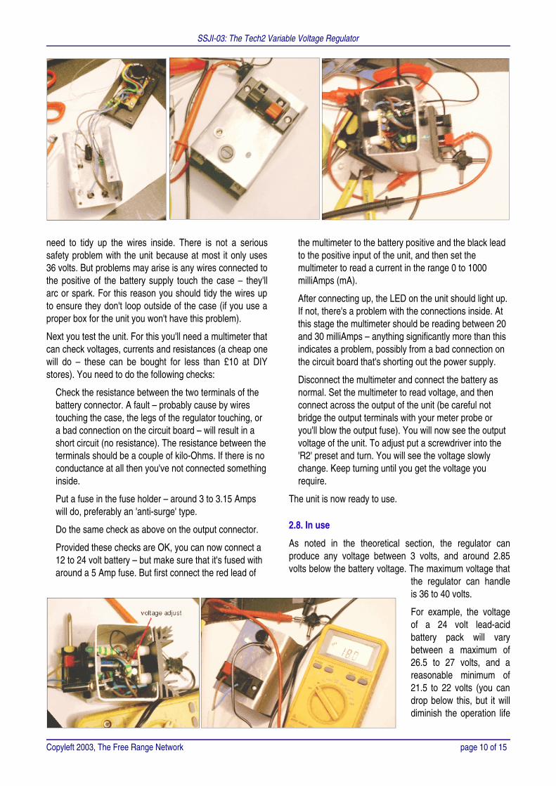
need to tidy up the wires inside. There is not a serioussafety problem with the unit because at most it only uses36 volts. But problems may arise is any wires connected tothe positive of the battery supply touch the case – they'llarc or spark. For this reason you should tidy the wires upto ensure they don't loop outside of the case (if you use aproper box for the unit you won't have this problem).
Next you test the unit. For this you'll need a multimeter thatcan check voltages, currents and resistances (a cheap onewill do – these can be bought for less than £10 at DIYstores). You need to do the following checks:
� Check the resistance between the two terminals of thebattery connector. A fault – probably cause by wirestouching the case, the legs of the regulator touching, ora bad connection on the circuit board – will result in ashort circuit (no resistance). The resistance between theterminals should be a couple of kilo-Ohms. If there is noconductance at all then you've not connected somethinginside.
� Put a fuse in the fuse holder – around 3 to 3.15 Ampswill do, preferably an 'anti-surge' type.
� Do the same check as above on the output connector.
� Provided these checks are OK, you can now connect a12 to 24 volt battery – but make sure that it's fused witharound a 5 Amp fuse. But first connect the red lead of
the multimeter to the battery positive and the black leadto the positive input of the unit, and then set themultimeter to read a current in the range 0 to 1000milliAmps (mA).
� After connecting up, the LED on the unit should light up.If not, there's a problem with the connections inside. Atthis stage the multimeter should be reading between 20and 30 milliAmps – anything significantly more than thisindicates a problem, possibly from a bad connection onthe circuit board that's shorting out the power supply.
� Disconnect the multimeter and connect the battery asnormal. Set the multimeter to read voltage, and thenconnect across the output of the unit (be careful notbridge the output terminals with your meter probe oryou'll blow the output fuse). You will now see the outputvoltage of the unit. To adjust put a screwdriver into the'R2' preset and turn. You will see the voltage slowlychange. Keep turning until you get the voltage yourequire.
The unit is now ready to use.
2.8. In use
As noted in the theoretical section, the regulator canproduce any voltage between 3 volts, and around 2.85volts below the battery voltage. The maximum voltage that
the regulator can handleis 36 to 40 volts.
For example, the voltageof a 24 volt lead-acidbattery pack will varybetween a maximum of26.5 to 27 volts, and areasonable minimum of21.5 to 22 volts (you candrop below this, but it willdiminish the operation life
Copyleft 2003, The Free Range Network page 10 of 15

SSJI-03: The Tech2 Variable Voltage Regulator
of the battery if done regularly). Therefore, with a 24 voltbattery, you can produce any voltage between 8 volts and19 volts.
The issue to consider is that the more you drop thevoltage, the more heat the regulator will have to dump intothe heat sink – and wasted. Therefore you should minimisethe voltage drop by changing the voltage of the battery(see table below). The other issue is the capacity of thebatteries used. For example, a laptop computer consumesaround 1.5 Amp on average, but this may rise to 2.0 Ampswhen the laptop's internal battery is charging. Batteries arerated in 'Amp-hours' (Ah) – but this is not a realistic value.You only want to use 50% of a deep-cycle sealed lead-acid battery's charge, otherwise you will damage it (andonly 25% for an ordinary SLA). So the available capacity ishalf the stated capacity. Therefore:� A 4Ah battery will run a laptop for 1.3 hours, but at
maximum capacity the regulator will run for 1 hour.� A 7Ah battery will run a laptop for 2.3 hours, but at
maximum capacity the regulator will run for 1.75 hours.� A 16Ah battery will run a laptop for 5.3 hours, but at
maximum capacity the regulator will run for 4 hours.� A 40Ah battery will run a laptop for 13.3 hours, but at
maximum capacity the regulator will run for 10 hours.
It would be very easy to wire together batteries to makethe required voltage. But nearly always you'll find that youneed more flexibility than that. For this reason the batterypack is wired to a four-way power connector – the typeused for power connections inside a PC computer, andwhich you can often pick up in the junk bins of computershops. The matching half of the power connector can thenbe configured in two ways:� Two of the terminals, corresponding to the positive
terminal of one battery and the nagative terminal of theother, are wired together. This means that the remainingtwo terminals provide positive and negative connectionsat 24 volts.
� The two positive terminals are connected together, asare the two negative terminals, and then connectionsare made to these two. This give twelve volts but attwice the power rating.
The major flexibility of this option is that you can connectthe regulator to the battery pack at one time, or connect,using a second power connector with the differentconfiguration of wires, a 12 volt appliance. The most likelycandidate being an inverter to convert 12 volts DC into 230volts AC to simulate mains power. This latter option usesmore power, and so the fact you have two batteries inparallel doubles the power available.
By using connectors in this way you can just plug in a
different connector to the battery pack to change theconfiguration from series to parallel, and vice versa, ratherthan physically re-wiring the batteries.
3. Components for the Tech2 Regulator
This page looks at the components required to build theTech2 regulator.
If you want to buy the components, rather than sourcethem for junk, everything can be obtained from MaplinElectronics. For further details of their catalogue, or wheretheir shops are located, see http://www.maplin.co.uk/.
Copyleft 2003, The Free Range Network page 11 of 15

SSJI-03: The Tech2 Variable Voltage Regulator
Circuit ref. Component Attributes Source/cost
IC1 L200C regulator L200 comes in various guises,each with a diffent code suffix.The 'C' variant is a plastic('Pentawatt') case with five legs.All variants work in a similarway.
Not likely to find as surplus, unless you rip them out ofsome old equipment. Maplin sell single L200CVregulators for £2.49, or £2.24 if you buy 5 or more (bothinc. VAT). Other component suppliers sell the L200 forless, but with various minimum purchase levels. Maplinorder code, YY74R.
R1 820R 0.25W metal filmresistor
Standard 820 Ohm resistor Available new from Maplin for a penny each, orrecovered from old equipment. However, older resistorsmay have a lower tolerance, or be degraded, which is aproblem as the accuracy needs to be within a fewpercent. Maplin order code M820R.
R2 5K Ohm or 10K Ohmpreset/potentiometer
Standard cermet preset. Similar values can be recovered from older electricalequipment. However it's better to have the multi-turntypes rather then the simple three-quarter turn types asyou can adjust the output voltage with greater accuracy.18 turn cermet presets available from Maplin for 79peach. Order code WR48C (5K preset) or WR49D (10Kpreset).
R3 High power resistor Value depends upon currentlimiting requirements – suggestthat you seriously consider notusing R3 and instead use a lowvalue fuse in FS1.
Low value resistors are available from wasteequipment, especially power supplies. The problem willbe the power rating. For most applications you aregoing to need resistors with a power rating of at least5W, but perhaps as high as 25W. Maplin have arestricted range of high power wire wound resistors.Other component suppliers, such as Farnell or RS,have a better selection but you will have to buy a certainminimum quantity. Expect to pay 10p to 50p dependingon the power rating. If ordering from Maplin, 3W, 7Wand 10W resistors available, but the 10W range hasonly a few preferred values.
R4 1k2 0.25W metal filmresistor
The actual value of this resistordepends upon the rating of D1
Most LEDs have a forward voltage of 2.0V to 2.2V, anda current rating of 15mA to 30mA. However, reating ofR4 depends upon output voltage, which might vary from3V to 36V. 1200 Ohm (1k2) is a value that's fairlysuitable across the popular voltages – 9V, 12V, 18V,and 24V. It should also suit most LED's current rating.Available new from Maplin for a penny each, orrecovered from old equipment. Tolerance is not critical(10%). Maplin order code M1K2R.
D1 Standard red or greenLED
Very roughly 2V forward voltageand 20mA to 30mA currentconsumption.
LEDs can be recovered from most electrical equipment.Unless they are made to work with higher voltages(5V/12V) or they are contain flashing chips, most 3mmand 5mm round or square LEDs should be suitable.New round 5mm LEDs can be bought from Maplin for10p each. Order code WL27E (red) or WL28F (green).
Copyleft 2003, The Free Range Network page 12 of 15

SSJI-03: The Tech2 Variable Voltage Regulator
Circuit ref. Component Attributes Source/cost
C1 10µF 63V electrolyticcapacitor
Lower voltage ratings are notsuitable since they should berated at at least twice the batteryvoltage. 63V (standard value forelectrolytics) or higher should beOK. 50V will probably do if usinga 24V battery pack or less.
10µF is a very common value, so you might be able torecover one from old equipment. But you are more likelyto find the 63V rated capacitors in power supplies or oldTVs where higher voltages are used. Maplin sell a 100Vradial version for 5p each, order code VH24B.
C2 0.22µF (or 220nF) resin-dipped ceramiccapacitor
Ceramic or polyester capacitorsare OK for smoothing a prettystable DC power source
0.22µF can be recovered from old equipment but youmight have problems identifying them – somemanufacturers use part codes instead of capacitancevalues on components. Maplin sell 0.22µF resin-dippedceramics for 9p each, order code RA50E.
C3 0.1µF (or 100nF) resin-dipped ceramiccapacitor
Ceramic or polyester capacitorsare OK for smoothing a prettystable DC power source
0.1µF can be recovered from old equipment but youmight have problems identifying them – somemanufacturers use part codes instead of capacitancevalues on components. Maplin sell 0.1µF resin-dippedceramics for 9p each, order code RA49D.
C4 1000µF, 100Velectrolytic capacitor
100V rating chosen to protectagainst the damage caused byreverse EMF created byinductive loads. Peak-to-peakvoltages returning from inductiveloads may approach 60V wherethe DC supply voltage is 20V orhigher. 63V capacitors would beOK where low voltage or non-inductive loads are used.Alternately you could just put ablocking diode in the output toCN2, but this will burn off moreenergy as it would drop another1V to 2V off the regulatedoutput. 1000µF has beenchosen as a reservoir capacitorsuitable for most applications.But with equipment that createsa lot of heavy power surges(e.g., audio amplifiers) it's notenough, and you'll need to gotwo or four times higher.
1000µF capacitors can be recovered from old powersupplies and TV – but be sure to check the voltagerating. Maplin sell 1000µF 63V capacitors for 59p each,order code VH52G. If you want to go for the higher100V capacitor, Maplin sell these for £1.49 each, ordercode VH53H.
CN1 Line connector Any variety of power connector,to suit your purpose, may beused. As CN1 connects to abattery all types of wire may beused. For this reason a levelconnector, like that used forloudspeaker connections, wouldallow the quick connection ofbare wires. Otherwise use astandard battery connector, orterminal posts with screw-fittings.
Power connectors can be recovered from many types ofportable equipment. Often the problem you'll have isfinding a plug to fit the socket. Connectors that acceptbare wires are useful in this application as you can thenuse any available wire to hook-up the power from thebattery pack. Maplin sell a wide range of connectors.But never use a mains connector for this purpose asyou risk someone plugging the mains supply into yourregulator
Copyleft 2003, The Free Range Network page 13 of 15

SSJI-03: The Tech2 Variable Voltage Regulator
Circuit ref. Component Attributes Source/cost
CN2 Line connector Any variety of power connector,but unlike CN1, more careshould be taken to reduce therisk of short-circuiting the output.
The 2.5mm power sockets on most portable equipmentwould do for this application. However, a panelmounting option would be better. It all depends whatyou can salvage from trash equipment. Otherwise,Maplin sell a variety of panel mounting powerconnectors. But as noted above, never use any type ofmains power connector.
FS1 20mm fuseholder, withfuse
Panel mounting fuseholderchosen – you could use a circuit-mounted or in-line fuseholder,but you'd have to open-up theenclosure to get at it. A 2A anti-surge fuse was used in theholder. 'Anti-surge' fuses willtolerate a current of slightly morethan 2A for a fraction of asecond before blowing. This isuseful when powering a laptopas the disk drive producetransient current drains. Formore sensitive equipment uselower rated fuses nearer to thecurrent consumption of thedevice. If the equipment is verysensitive, use 'quickblow' fuses.
20mm fuses can be found inside older equipment – notall new equipment uses them because switched modepower supplies are fairly stable. Likewise, where there'sfuses you'll be able to recover fuseholders. Maplin sellpanel mounting 20mm fuseholders for 99p each, ordercode DA59P. Maplin also sell packs of 10 anti-surge (or'time delay') fuses, in a variety of power ratings for£1.79 each, or packs of 10 quickblow fuses for 79peach.
Heat sink TO220-style heat sink Ideally you should look for aheat sink that's rated 10°C/W to15°C/W to handle the heat loadeasily
A heat sink can be any lump of aluminium, but it helps ifit has fins to increase the surface area. A section ofaluminium window extrusion or box section, 10cm longand 3cm to 5cm wide, would qualify as a minimal heatsink. You can also recover some large heat sinks fromolder power supplies, stereo amplifiers and TVs. Maplinstock a variety of heat sinks suitable for this purpose.
Strip board Standard SRBP matrixboard 0.1" matrix boardwill do, provided that you'reinforce' certain part ofthe copper strips toincrease currentcapacity.
Good matrix board doesn't tendto get thrown away. Thereforeyou'll have to buy it.
Maplin stock various sizes of board. A piece twice asbig as required for this project (order code JP46A) cost79p. But it's probably more cost efficient to buy thelargest board they have and cut it down for each projectyou develop (cost around £4).
Case A metal case Metal cases are preferred overplastic cases because theyradiate more heat. Anotheroption would be to fold a sheetof metal to form a squared 'U'shape and then screw or boltthis to your heat sink to form the4th side of your enclosure.
Any type of metal box or other enclosure can be used.The important thing is that it should protect the internalcomponents, whilst having enough space to ensure thatthe components need not be squashed inside the box.Also, unless you isolate the regulator from the heat sink,and some power connectors from the case, the box willbe connected to the negative supply of thebattery/power supply. You must ensure that no part ofthe positive supply has a chance to touch the inside ofthe enclosure. But if you want things plain and simple,Maplin sell a variety of metal enclosures suitable for thisapplication – for example their aluminium instrument orchassis cases, costing £3 to £10.
Copyleft 2003, The Free Range Network page 14 of 15

SSJI-03: The Tech2 Variable Voltage Regulator
Circuit ref. Component Attributes Source/cost
Battery A battery pack The battery pack should bedesigned to suit your need forvoltage and capacity – this isdiscussed at length in the text ofthe 'theoretical' section. SealedLead Acid (SLA) batteriesusually come in 6V or 12V cells,and in a variety of capacities.
Most of the surplus SLA batteries you may obtain arelikely to be near the end of their lives. This can createproblems when putting two or three together becauseeach has a different discharge characteristic. Maplin sellnew SLAs in a variety of capacity, and in low (cheap)and high (expensive) quality versions. Capacities varyfrom 1Ah to 65Ah. They also sell 'deep cycle' SLAs(DC-SLAs). For a good quality, 12V, 12Ah SLA expectto pay £35 each. A 12V, 17Ah deep discharge DC-SLAcosts £60.
Battery fuse Automotive fuseholderwith blade fuse
Automotive fuses have theadvantage that they're cheapand easy to obtain.
You can obtain old automotive fuseholders fromgarages and vehicle breakers. Fuses can be boughtcheaply at markets and DIY stores. Maplin sell an inlinefuseholder, rated at 30A, for £1.29 (order code KK80B).A variety of blade fuses from 3A to 5A are available for29p each.
Batteryconnector
Connectors to suit yourparticular battery pack
Different types of SLA havedifferent types of connector.Some have push connectorsthat crimp onto wires. Highercapacity batteries have clampconnectors. You'll need to getthe types of connector that suityour battery.
The nature of these connectors is such that you areunlikely to find usable connector in the trash. DIYstores, and even Argos, stock crimp connector sets thatare useful for wiring up battery packs – however younearly always don't have enough of the type ofconnector you require. Automotive spares dealers willalso sell crimp connectors and battery clamps.Otherwise, Maplin sell a variety of crimp and clampconnectors.
The Salvage Server Project has been developed by the Free Range Network to promote the use of redundant IT equipment as a resource for community and grass rootscampaigning organisations. This report has been produced to support the work of the project, and is made freely available to encourage the objectives of the project.
© Copyright 2003, Paul Mobbs/Free Range Network. Permission is granted to copy, distribute and/or modify this document under the terms of the GNU FreeDocumentation License, Version 1.2 or any later version published by the Free Software Foundation; with Invariant Sections being the document title and authoridentification, no Front-Cover Texts, and no Back-Cover Texts. A copy of the license is provided at: http://www.fraw.org.uk/_admin/rights.shtml This document has beenwholly produced using the Gnu/Linux operating system and free software.
The information contained in this work has been obtained from sources that are believed to be reliable. However, We cannot provide any absolute guarantee that theinformation contained herein is wholly correct, or that the manner in which the information is used is correct, and consequently we cannot be responsible for any error,omissions or damages arising from the use of the information in this work. This work has been created on the basis that the Free Range Network is not intending tosupply engineering or any other professional services – the purposes of this briefing are merely illustrative.
Copyleft 2003, The Free Range Network page 15 of 15