the telescope program for the national radio astronomy observatory at green bank, west virginia
TRANSCRIPT
Emberson and Ashton: Telescope for the National Radio Astronomy Observatory
Using fluctuation voltage it is possible14 to deduce thesize of the elementary charges causing this voltage.When the result was published, a value correspondingto three electrons was given. This was an error causedby an incorrect and much too low value of capacity.Afterwards, the mistake was found and the proper valueof electron charge secured in agreement with othermethods.
These old experiments at Wheaton were quite thrill-ing at the time. My present experiments3 at the otherend of the spectrum in Tasmania using cosmic static atkilometer wavelengths fully equal the old in the realmof the unexpected.Much remains to be done.23 Grote Reber, 'Between the atmospherics," J. Geophys. Res. (in
press).
The Telescope Program for the National RadioAstronomy Observatory at Green Bank,
West Virginia*
R. M. EMBERSONt, SENIOR MEMBER, IRE, AND N. L. ASHTONt
Summary-A brief account is given of the initiation of the feasi-bility study on the establishment and operation of the NationalRadio Astronomy Observatory at Green Bank, West Virginia. Theprincipal research facilities will be the radio telescopes, and a seriesof such telescopes have been proposed. The desired performancecharacteristics are reviewed. A 140-foot steerable paraboloid on anequatorial mount has been designed. The steps leading to this de-sign are described, as well as the general features of the designedand the expected operating performance. The National Radio Astron-omy Observatory is being sponsored by the National Science Foun-dation.
INTRODUCTION
N January, 1954, a conference' on radio astronomywas held in Washington, D. C., jointly sponsoredby the National Science Foundation, the California
Institute of Technology, and the Department of Ter-restrial Magnetism of the Carnegie Institution of Wash-ington. Participants included both United States scien-tists and engineers, as well as numerous distinguishedforeign visitors. The conference made clear to the USparticipants that the lead in radio astronomy had beentaken by other countries, this despite such noteworthycontributions as Karl Jansky's initial discovery,2 G. Reb-er's pioneering work,3 the tremendous advances in our
* Original manuscript received by the IRE, November 8, 1957.This work was supported by the National Science Foundation.
t Associated Universities, Inc., New York, N. Y.t University of Iowa, Iowa City, Iowa.1 "Proceedings of conference on radio astronomy, January 4-6,
1954," J. Geophys. Res, vol. 59, p. 140; March, 1954. See also "RadioAstronomy Conference," Science, vol. 119, p. 588; April 30, 1954.
2 K. Jansky, "Directional studies of atmospherics at high fre-quencies," PROC. IRE, vol. 20, pp. 1920-1932; December, 1932.
-, "Electrical disturbances apparently of extraterrestrial origin,"PROC. IRE, vol. 21, pp. 1387-1398; October, 1933.
3 G. Reber, "Cosmic static," PROC. IRE, Vol. 28, pp. 68-70;February, 1940.
-, Astrophys. J., vol. 91, pp. 621-632; June, 1940.
electronics techniques, particularly those related to ra-dar and radio communications, and the first observationof the 1420-mc radiation of interstellar hydrogen byEwen and Purcell.4 The conference also indicated thatUS radio astronomy would fall behind further andfurther if steps were not taken to provide observing fa-cilities comparable to those planned or being built inother countries.The equipment requirements of radio astronomers
are of three general classes: the antenna system; the re-ceiver and data processing equipment; and the ancillarypower supplies, time and frequency standards andsimilar items. In most instances, the antenna is, by far,the most costly part of the observing equipment. Be-cause of the cost and other factors most US radioastronomers have been working with antennas that aresmaller and less effective than those of foreign scientists,who, soon after World War II, gained support of theirrespective governments for the construction of largeradio astronomy equipment. The smaller size, or gain ofan antenna, can be compensated for in part throughbetter electronics-a receiver with a better noise figureand extreme stability to permit integration of the veryweak celestial signals over longer periods of time; butfor angular resolution and the avoidance of confusion,which is important to astronomers, there is no substi-tute for aperture size. Hence, the conclusion from theJanuary, 1954, conference was that larger and more ef-fective antennas were needed in the United States. Howto obtain them was another question. The suggestionwas made that several institutions might join together
4 H. I. Ewen and E. M. Purcell, Nature, vol. 168, p. 356; 1951.
1958 23
PROCEEDINGS OF THE IRE
in the construction of a large antenna, larger than anysingle institution could afford. In the spring of 1954,there were conversations between representatives ofHarvard, Massachusetts Institute of Technology, andthe Naval Research Laboratory on a proposal to con-struct a large steerable paraboloid. This would be a gen-eral purpose research tool, applicable to astronomicalproblems as well as to more immediately utilitarianstudies, such as scatter propagation. The enthusiasm ofthe scientists and engineers was dampened by the highestimated cost of a large paraboloid. But the conversa-tions continued, and a parallel was found in the researchreactor and large accelerators at the Brookhaven Na-tional Laboratory. This laboratory was established andis operated by Associated Universities, Inc.5 under acontract with the Atomic Energy Commission. Theresearch facilities there are enjoyed by visiting scientistsas well as by those on the permanent staff. Why notestablish a radio astronomy observatory along the samegeneral pattern?
After further conferences, the National Science Foun-dation made a grant to Associated Universities, Inc. fora study on the feasibility of establishing and operating aradio astronomy observatory. The study included asearch for a suitable site, plans for the site development,several investigations contributing to the design andconstruction of large antennas, and a plan for the or-ganization and operation of the proposed observatory.'More recently, the National Science Foundation hascontracted with Associated Universities, Inc. to estab-lish and operate a National Radio Astronomy Observa-tory at Green Bank, West Virginia.
In the remainder of this article, the portion of thefeasibility study and of subsequent contract activitiesrelated to large antennas will be discussed. To help inunderstanding decisions that have been made, it is de-sirable to recognize that what an engineer regards as anantenna system is a telescope to the astronomer, andthe astronomer routinely deals with signals that thecommunication engineer would regard as a smallamount of noise. The term "telescope" will be employedin deference to the nomenclature of the astronomers,and we will regard it as an instrument for research, eventhough the tonnage of materials involved are about thesame as for a destroyer.The nature of the signals studied by radio astrono-
mers is described in other articles in this issue of thePROCEEDINGS.7 Let us note briefly here that the signalsare weak as judged by radio communications or radar
* Associated Universities, Inc. is a nonprofit corporation charteredby the Board of Regents of the State of New York; the corporationis sponsored by nine universities: Columbia, Cornell, Harvard, JohnsHopkins, Massachusetts Institute of Technology, Pennsylvania,Princeton, Rochester, and Yale.
6 B. J. Bok, "A national radio observatory," Sci. Amer., vol. 195,pp. 56-64; October, 1956.
L. V. Berkner, 'National radio observatory site," Sky and Tele-scope, vol. 15, p. 398; July, 1956.
7 J. W. Findlay, 'Noise levels at a radio astronomy observatory,"this issue, p. 35.
standards. All wavelengths transmitted by the earth'satmosphere are represented (e.g., from less than 1-cmwavelength to more than 10 meters). There are somefrequencies of particular astronomical importance be-cause of relatively strong bright-line radiations associ-ated with natural atomic and molecular processes, (e.g.,the 21-cm radiation of the hydrogen atom). The typicalcelestial radiation is unmodulated white noise, andin some cases may be polarized. The signals come frommany sources from the sun, from the center of ourMilky Way system or galaxy, from un-ique objects suchas the Crab Nebula, from external galaxies, and fromsources of such low visual luminosity that no opticalidentification has been possible. All that precedes is conI-cerned with radio astronomy in the passive or receiving-only phase, wherein the transmitters are natural phe-nomena and not under the control of the experimenter.The active or radar phase of radio astronomy is limitedto the solar system, and there is no sharp line of de-marcation between these studies and those of the upperatmosphere that stem from geophysical and radio com-munications interests. Throughout this paper the dis-cussion will generally be directed to the passive phase ofradio astronomy, but most of what is said is equally ap-plicable to the active phase.
GENERAL DISCUSSION
At the outset, the Advisory Committee8 for thefeasibility study pointed out that the observing require-ments in the microwave region required a telescope withboth high gain and high resolution. At meter wave-lengths and longer, high resolution was the dominantrequirement because of the more satisfactory status ofthe receiver art for such radiations. It was also notedthat resolution at the longer wavelengths was a linearaffair, e.g., a simple array or Mills Cross,9 whereas thehigh-gain, high-resolution telescope for microwaveswould involve a paraboloid, or something equivalent,and the cost would vary as the square or some higherpower of the aperture. Thus a concept for the telescopesat Green Bank was formed early, namely, that the rela-tively expensive paraboloids would be part of the perma-nent equipment, whereas arrays would be regarded asexpendable equipment and tailored to fit the particularneeds of each observing program. This concept recog-nizes that a paraboloid is inherently a broad-band de-
8 The feasibility study started early in 1955, with an AdvisoryCommittee under the chairmanship of J. P. Hagen, Naval ResearchLaboratory, and composed of B. J. Bok, Harvard College Observa-tory; A. J. Deutsch, Mt. Wilson and Palomar Observatories; H. I.Ewen, Harvard College Observatory; L. Goldberg, University ofMichigan; W. E. Gordon, Cornell University; F. T. Haddock, Uni-versity of Michigan; J. D. Kraus, Ohio State University; A. B.Meinel, University of Chicago; M. A. Tuve, Carnegie Institution ofWashington; H. E. Wells, Carnegie Institution of Washington; andJ. B. Weisner, Massachusetts Institute of Technology. When Dr.Hagen was made the head of Vanguard, he resigned his position onthe Advisory Committee, and Dr. Bok served as chairman until heleft to become the director of the Australian National Observatory.
9 B. Y. Mills, A. G. Little, K. V. Sheridan, and 0. B. Slee, 'A highresolution radio telescope for use at 3.5 cm," this issue, p. 67.
24 January
Emberson and Ashton: Telescope for the National Radio Astronomy Observatory
vice, limited at one extreme when the aperture is thesame order of magnitude as the longest wavelength tobe observed, and at the other extreme when the irregu-larities of the paraboloid surface (openings, if a mesh;deviation from the best-fitting true paraboloid) are asignificant fraction of the shortest wavelength.
There have been numerous theoretical studies on theshort-wavelength limitations of paraboloid surfaces.10Experimental evidence and the theoretical predictionsare in general agreement, Friis" and his colleagues hav-ing shown with the Homdel 60-foot paraboloid that sur-face deviations of 1/16th the observed wavelength havesignif cance if utmost gain is the objective. From theexperimental point of view, the radio astronomer doesnot have a free choice of what wavelength will be ob-served. There are practical factors of interference fromman-made sources. If these devices are intentionaltransmitters, they generally radiate in fixed bandswhich the radio astronomer will try to avoid. The as-tronomers are also limited by the transparency of theearth's atmosphere. And, finally, the celestial radiationshave a continuum plus certain bright lines (sometimesthese may be observed as absorption lines,"2 similar tothe Fraunhofer lines in the solar spectrum). As previ-ously mentioned, one of the most important of these"bright lines" is the 21-cm radiation from atomic hydro-gen, because hydrogen is a fundamental building blockof the universe and the most abundant element foundnot only throughout our Milky Way system, but inother galaxies as well. Because of the great importanceof this hydrogen radiation, any general purpose radiotelescope must be capable of working effectively at 21cm.'3 Thus it is seen that, independent of the diameter,a paraboloid for a radio astronomy telescope must meeta surface tolerance of ±2 inch to be ideal for 21-cmwork; of course, the paraboloid would have value if thesurface irregularities were greater than 1/16th the wave-length, but the over-all antenna gain would suffer. Fur-thermore, if the irregularities were systematic in char-acter because of the manufacturing process, curious
10 S. Silver, Ed., "Microwave Antenna Theory and Design,"Mass. Inst. Tech. Rad. Lab. Ser., vol. 12, McGraw-Hill Book Co.,Inc., New York, N. Y.; 1949.
R. C. Spencer, "Multiple Feed High-Gain Antennas for RadioAstronomy," paper presented at IAU conference; May 27, 1955.
D. J. Cheng, "Study of Phase Error and Tolerance Effects inMicrowave Reflectors," Syracuse Univ. Res. Inst., Syracuse, N. Y.,Contract No. AF 30(602)-924; December 31, 1955.
11 J. Robieux, "Influence of the Manufacturing Precision of anAntenna on its Performance," Compagnie Generale de T.S.F., Paris,France, Contract No. AF 61(514)-737C; May 27, 1955.
A. B. Crawford, H. T. Friis, and W. C. Jahes, Jr., "A 60-foot di-ameter parabolic antenna for propagation studies," Bell Sys. Tech.J., vol. 35, pp. 1199-1205; September, 1956.
J. Ruze, "Physical Limitations on Antennas," Mass. Inst. Tech.,Res. Lab. Electronics, Cambridge, Mass., Tech. Rep. No. 248;1952.
12 A. E. Lilley, "The absorption of radio waves in space," Sci.Amer., vol. 197, pp. 48-55; July, 1957.
13 The giant 250-foot telescope of the University of Manchester,nearing completion at Jodrell Bank, was conceived by Prof. Lovellbefore the hydrogen radiation had been observed: a redesign of thereflector has been accomplished while the telescope was being con-structed in order that 21-cm observations might be undertaken.
effects might be introduced into some experiments, suchas polarization measurements.With the minimum acceptable specification for the
surface tolerance essentially predetermined, there re-mains for selection only the diameter and focal length(or f/d ratio). Of these, the f/d ratio is the easier to fix.The choice depends primarily on the rf feed that will beplaced at the focus to "illuminate"''4 the paraboloid.Here some compromises are necessary, although thereis general agreement that the f/d ratio should be lessthan 0.5 and greater than 0.25. A ratio of 0.5 wouldhave certain advantages if multiple feeds or clusters areemployed at the focus. But the consensus is that an f/dratio of 0.40 to 0.45 is best for horn-type feeds, whichwill be employed for work at 21-cm and shorter wave-lengths.The diameter of the paraboloid may not be freely
chosen. As already mentioned, the cost of a radio tele-scope varies as some power, greater than two, of the di-ameter; and because of the predetermined surface spec-ification, the structural problems of the telescope areimportant factors. Early in the feasibility study for theradio astronomy observatory, structural engineers wereasked to estimate at what size a conventional steerableparaboloid, such as the Jodrell Bank telescope, would belimited by the strength of the materials available for itsconstruction. The answer to this question is not unique,depending on what assumptions are made. To illustrate,consider a simpler structure, namely, a tower. It is per-haps technically feasible to construct a tower 29,000feet tall and meeting quite strict specifications for rigid-ity. The completed structure might closely resembleMount Everest and would be fantastically costly. If anequally extreme design were adopted for a telescope, atruely enormous aperture might be obtained; but ifmore or less conventional designs are visualized, aper-tures of two to three thousand feet should be possiblebefore the physical characteristics of the structural ma-terials would be limiting. There was unanimous agree-ment that the cost of such a telescope would be beyondthe budget available for the initial establishment of theobservatory.The above considerations gave rise to numerous sug-
gestions for unconventional or exotic designs-hugebowls carved in the surface of the earth; a floatingsphere with the paraboloid set into the upper portion;phased panels arranged to be equivalent to an opticalzone or Fresnel lens. These suggestions were rejectedas being unproven and, hence, too great a gamble forinclusion in the early planning stages for the observa-tory or as being limited in applicability to general re-search problems. Even the so-called conventional ap-proach offers very many solutions, depending on the dc-tailed choices made by the designer. As the studies pro-
14 In the discussion of antenna patterns, the usual custom isadopted for a transmitting system rather than for a passive receiving-only system.
1958 25
PROCEEDINGS OF THE IRE
ceeded, it became evident that there was no uniquelybest design for a radio telescope, even if the problemwere narrowed by closely specifying the diameter andother performance characteristics.At the same time that the preceding studies were
undertaken, an investigation was made of the feasi-bility of housing very large telescopes in a radome,thereby relieving the telescope of most climatic dis-turbances, particularly winds and solar heating. Twotypes of radomes were considered: those made of flexiblematerial and supported by air ;15 and those made ofrigid, self-supporting surface panels.16 Both types havebeen employed to house military radars. In theory, theair supported type is more attractive, because the ab-sence of any thick struts or braces would eliminatemany possible secondary sources that might introducespurious signals or distorted polarization effects. It isimportant to note here that a military radar operates atessentially a fixed wavelength and the characteristics ofa rigid radome may be selected so as to minimize thepossible diffraction and interference effects; radio as-tronomy, on the other hand, is interested in wave-lengths from 1 cm to 10 m and it is not possible to"broad band" the structural radome design for this largeportion of the spectrum. On the other hand, the air sup-ported fabric for a radome could be kept thin, comparedeven to a 3-cm wavelength and could be made veryhomogeneous; acceptable dielectric and absorption con-stants were predicted from measurements made on thematerials used in the military radomes.'7 A tentativedesign was made for a radome large enough to house a500- or 600-foot telescope. In order that the radomewould not burst when the barometric pressure fell (orthat the fabric would not droop on the telescope whenthe barometric pressure rose), automatic fans or blowerswould be necessary to move air in or out of the radome.These and related technical problems could be solved,but no assurance could be obtained on the life of theradome fabric exposed continuously to climatic factors.Five or ten years is a long time by military standards:many equipments are obsolete in shorter times. But byastronomical standards, a radome life of 25 years seemedto be minimal. The presently available radome ma-terials cannot promise such durability, even with carefulannual maintenance at a considerable cost. The combi-nation of maintenance cost and capital outlay amortizedover a few years is prohibitive. Accordingly, a funda-mental decision was made to design all telescopes to
15 W. Bird, "Design and Fabrication of Experimental Radomeand Associated Equipment,' Cornell Aeronaut. Lab., Ithaca, N. Y.,1954. See also Life, May 9, 1949 and January 4, 1954.
16 R. B. Fuller, "Industrial logistics and design strategy," Penn.Triangle, Army-Navy-Air Force J., vol. 2, October, 1954. See alsoprivate communications and presentations, IAU conference; March25, 1955.
17 L. C. Van Atta, private communication:Material Dielectric Loss
Constant (at 3000 mn)S-82D Fiberglass 4.57 0.039S-84D Nylon 3.50 0.041.
stand in the open. This decision was made with fullrecognition that observations requiring the utmost per-formance of the telescope would have to wait for favor-able observing conditions, e.g., little or no wind, over-cast sky or at night, to minimize thermal effects.The 250-foot telescope at Jodrell Bank, which was
well started in 1955, elicited the suggestion that a largertelescope be considered for the observatory at GreenBank. Accordingly, a study was undertaken,18 not forthe immediate purpose of designing and constructingthe larger telescope, but primarily to learn what struc-tural problems would be involved. A diameter of 600feet was assumed for the paraboloid, with the addedstipulations that the telescope be effective for 21-cmwork and that structural materials be employed eco-nomically, in the hope that the cost might be held down.The results of the study were that the cost would exceed$10 million and that the performance specificationscould not be met unless either enormous quantities ofmaterials were employed (the Mount Everest solution),or compensating devices were incorporated. The lattersolution appeared more feasible and was explored to de-termine the nature of the compensation that would beneeded. An altazimuth mount, similar to that of theJodrell Bank telescope, had been adopted for the 600-foot study, and this proved to be an advantage whencompensations were added because gravity deforma-tions were single-valued functions of the altitude angle.By this point in the feasibility study for the radio as-
tronomy observatory, a telescope program had beenformulated, as follows:
1) A small telescope (10- or 20-foot aperture) mountedon the roof of the laboratory building to be avail-able for testing electronic components undergoingalignment or repair, and otherwise to be availablefor observation;
2) An intermediate telescope, perhaps similar to the60-foot telescope at Harvard's Agassiz Station;"9
3) A 140-foot telescope, to be a precision instrument,comparable in precision at its size to the 50-foottelescope at the Naval Research Laboratory;
4) A 300-foot telescope, to be a precursor for a largertelescope;
5) A 600-foot telescope, perhaps the largest com-pletely steerable paraboloid to be built;
6) Provision for arrays and for mobile equipmentbrought by visiting astronomers.
More recently, the telescope program has been modifiedto include more than one of the intermediate telescopes,item 2). Some consideration is being given to abandon-ing the fourth and fifth items in favor of a very muchlarger telescope, increased gain and resolution being
18 J. Feld, "Feasibility Study of 600-foot Diameter Radio As-tronomy Reflector," private communication; July 20, 1955.
19 D. S. Heeschen, "Harvard's new radio telescope," Sky andTelescope, vol. 15, pp. 388-389; July, 1956.
26 January
Emberson and Ashton: Telescope for the Nattonal Radio Astronomy Observatory
bought at the expense of steerability or sky coverage.The 140-foot telescope is the most challenging prob-
lem of the present program. The specifications for thisinstrument were drafted in 1955 and are reproduced asfollows, along with revisions that seemed desirable asthe design studies proceeded.
1) Focal length/diameter ratio, 0.35 to 0.5, with thelarger value preferred;
2) Surface tolerance, ± 8 inch over the entire apertureand ± 4 inch over the inner half aperture;
3) Surface material, to be electrically equivalent to acontinuous sheet with the largest dimension of anyopening not more than 1 inch;
4) RF feed support, capable of a 500-pound load heldto 8 inch of correct position;
5) Rigidity and drive and control system to be capableof an accuracy of 5 per cent of the beamwidth athalf power for 10-cm radiation, or about 30" ofarc. Design for normal use in winds to 30 mph andwith slight reduction of accuracy in winds to 45mph. In addition to a polar axis tracking rate, bothaxes will have a variable scanning rate, from 10' to40 per minute of time, and a maximum slew rateof 30° per minute of time.
By the fall of 1955, it seemed desirable to amend thespecifications, the paraboloid tolerance over the entiresurface being reduced to ±+ inch and the angular pre-cision of the instrument set at 5 per cent of the half-power beamwidth for 3-cm radiation or 10" of arc.About a year later, further revisions were made. Theprecision desired for the paraboloid surface was rede-fined, as follows: For wind speeds up to 16 mph, theroot-mean-square deviation from the best paraboloidshall be no more than + 1 inch for all positions of theparaboloid. Under a no-wind condition and for zenithdistances of less than 600, the surface accuracy shouldbe as much better than +± inch as can be obtainedwithout appreciably increasing the cost of the reflector.The paraboloid surface shall be adj ustable by meansof rear-mounted studs or other means. The number ofrigid panels that make up the surface shall be kept assmall as is consistent with the surface tolerances de-manded of the panels. The specifications for the rigidityof the mount and for the drive and control system weremodified to include conditions of no wind and of 16 mph;it appeared that at Green Bank the winds would be lessthan 16 mph for at least 80 per cent of the time.
Wind Condition Zero Wind 16-mph Wind
Absolute pointing accuracy ±30" +40"Relative pointing accuracy* ± 10" + 20"Tracking accuracy over 15 min-
ute time ±10" ±20"Tracking accuracy over 1 hour
or more ±20 ±40'* Relative pointing accuracy is defined as the accuracy with which the telescope
can be moved from one point to another point, assuming the subtended angle be-tween points is under 30° and that both points are 30° or more above the horizon
Concerning over-all rigidity, it was specified that theentire structure be designed to act as a simple elasticbody for all expected gravity or wind loads, in additionto the general understanding that such deflections ordeformations be kept as small as might be consistentwith an economical employment of structural members.The specifications for the support of the rf feed were
modified to accommodate anticipated requirements formore complex and, hence, more bulky and heavierequipment to be held at or behind the focus; to providefor a load of 1000 pounds; and to be supported by atripod or tetrapod mount, the mounting base or plate tobe not less than 4 feet behind the focus. Deflections dueto gravity, as the telescope is moved about the sky,should be not more than 8 inch laterally from the axisof the paraboloid. A tolerance of 1/16 inch is desirableif it can be achieved at no great additional expense. Thefocal length shall be 60 feet, making the f/d ratioabout 0.43.
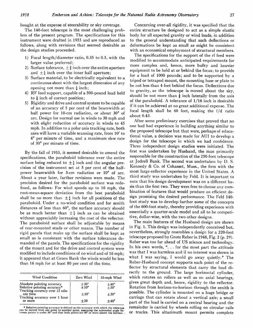
After some preliminary exercises that proved that noone had had experience in building anything similar tothe proposed telescope but that were, perhaps of educa-tional value, a decision was made for AUI to develop adesign for the telescope in which we had confidence.Three independent design studies were initiated. Thefirst was undertaken by Husband, the man primarilyresponsible for the construction of the 250-foot telescopeat Jodrell Bank. The second was undertaken by D. S.Kennedy & Co. of Cohasset, Mass., the firm with themost large-reflector experience in the United States. Athird study was undertaken by Feld. It is important tonote that his design development was on a different ba-sis than the first two. They were free to choose any com-bination of features that would produce an efficient de-sign promising the desired performance. The Feld 140-foot study was to develop further some of the conceptsof the 600-foot study, thereby providing experience withessentially a quarter-scale model and all to be competi-tive, dollar-wise, with the two other designs.The main features of the Husband design are shown
in Fig. 1. This design was independently conceived but,nevertheless, strongly resembles a design for a 220-foottelescope proposed by Grote Reber in 1948, Fig. 2 (p. 29).Reber was too far ahead of US science and technology.In his own words, ". . . for the most part the attitudewas that I was harmless and if no interest was shown inwhat I was saying, I would go away quietly." TheReber-Husband concept supports each point of the re-flector by structural elements that carry the load di-rectly to the ground. The large horizontal cylinder,which rotates on rollers as well as on axial bearings,gives great depth and, hence, rigidity to the reflector.Rotation from horizon-to-horizon through the zenith ispossible. The cylinder is mounted on a huge bridge orcarriage that can rotate about a vertical axis; a smallpart of the load is carried on a central bearing and theremainder is carried by wheels rolling on circular railsor tracks. This altazimuth mount permits complete
1958 27
PROCEEDINGS OF THE IRE
Do guVmO Vt - WNS so - soEn
_ Lano_ = I_s.
ItffN..,- -.00.0n
IdEb.
W -W- -
FA. toom.
Fig. 1-Drawing by Husband & Company of Sheffield, Eng. for the proposed 140-foot altazimuth telescope design. The two end elevationsshow the reflector pointed to the zenith and horizon. The front elevation again shows the reflector pointing to the zenith. The plan viewshows the quadraple support for the antenna feed.
coverage of the sky. In order to track a celestial object,i.e., to point the telescope constantly in one directionin space by compensating for the rotation of the earth,it is necessary that there be simultaneous motions aboutboth the altitude and azimuth axes. This coordinateconversion from altitude and azimuth (or elevation andbearing, for those trained in other services) to the as-tronomers' hour angle and declination (most easily un-derstood as the celestial counterparts of terrestrial longi-tude and latitude) will be discussed in more detail later.
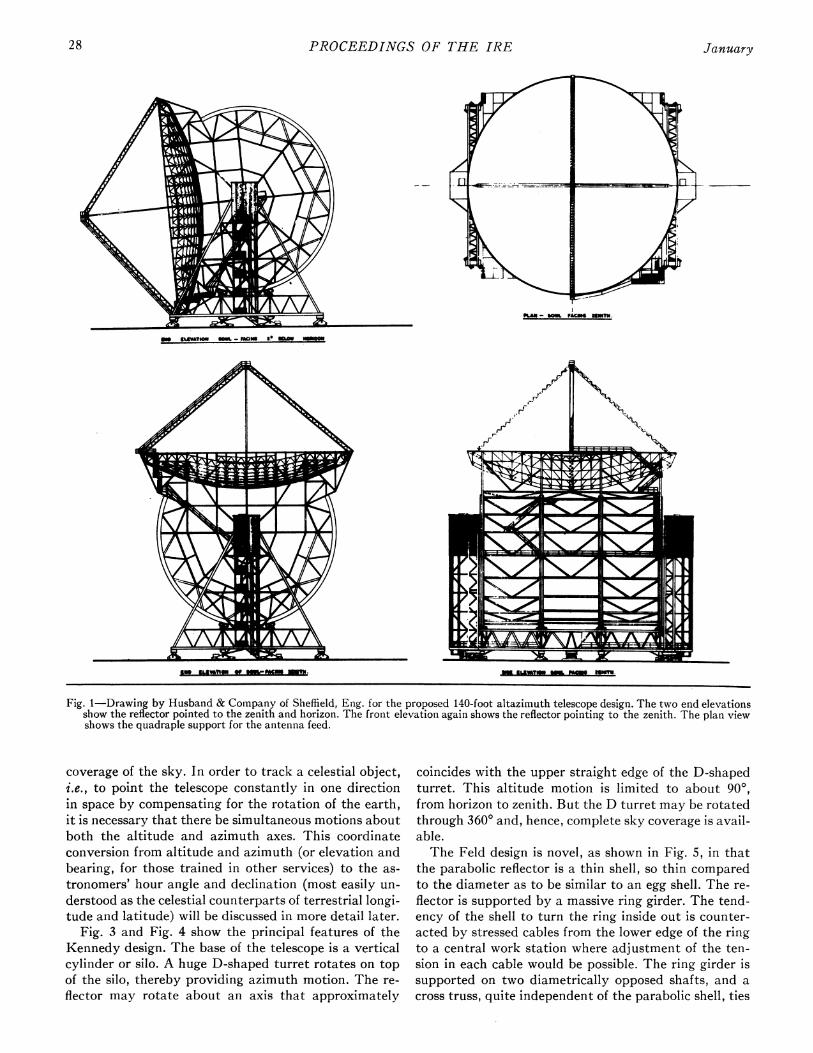
Fig. 3 and Fig. 4 show the principal features of theKennedy design. The base of the telescope is a verticalcylinder or silo. A huge D-shaped turret rotates on topof the silo, thereby providing azimuth motion. The re-flector may rotate about an axis that approximately
coincides with the upper straight edge of the D-shapedturret. This altitude motion is limited to about 900,from horizon to zenith. But the D turret may be rotatedthrough 3600 and, hence, complete sky coverage is avail-able.The Feld design is novel, as shown in Fig. 5, in that
the parabolic reflector is a thin shell, so thin comparedto the diameter as to be similar to an egg shell. The re-flector is supported by a massive ring girder. The tend-ency of the shell to turn the ring inside out is counter-acted by stressed cables from the lower edge of the ringto a central work station where adjustment of the ten-sion in each cable would be possible. The ring girder issupported on two diametrically opposed shafts, and across truss, quite independent of the parabolic shell, ties
28 January

Emberson and Ashton: Telescope for the National Radio Astronomy Observatory
Fig. 4-Rear elevation of Kennedy design, showingtruss structure of the reflector.
Fig. 2-Revolutionary concept of 220-foot radio telescopedesigned by Grote Reber.
- : '_ 1~T - --~ 77 _
Fig. 5-General view of the 140-foot altazimuth radio telescopedesign proposed by Dr. Jacob Feld of New York, N. Y.
Fig. 3-General side elevation of 140-foot altazimuth telescopeproposed by D. S. Kennedy Company of Cohasset, Mass.
these shafts together. Rotation through 3600 on theseshafts permits the reflector to point from horizon to
horizon and also, when the reflector is in the invertedposition, brings the paraboloid focus down for easy
access, a desirable feature if frequent changes or adjust-ment of the rf feed and other focal region components
are necessary. A bridge and tower system, similar inappearance to the 250-foot telescope, provides azimuthrotation through 3600. In this instance, most of thegravity load is carried on the central bearing and thewheels and circular tracks are to take care of wind loads.
These three designs, dissimilar as they appear, have
one thing in common: all are altazimuth mounts. Inretrospect, this coincidence is not surprising. The de-signers were given desired performance specificationsand asked to provide a telescope to give that perform-ance. Each approached the problem from a structuralpoint of view and each adopted the altazimuth mountas the simplest and most economical structure. Whetheror not the altazimuth concept for a telescope is thecheapest when drive and control as well as structure areconsidered is another matter. Numerous factors are in-volved. Reference has already been made to the factthat astronomers usually employ a celestial coordinatesystem of hour angle and declination. Hour angle ismeasured east or west of the local meridian plane, justas longitude on the earth is measured east or west of theGreenwich meridian. Declination is measured north orsouth of the equator plane. Most astronomical opticaltelescopes are equatorially mounted: there is a polaraxis parallel to the earth about which hour angle is
1958 29
PROCEEDINGS OF THE IRE
generated, and there is a declination axis perpendicularto the polar axis about which declination is generated.The preference for an equatorial mount is dictated bythe observational requirement that the telescope becapable of pointing continuously and precisely at anychosen celestial object.
If only approximate celestial tracking is required, theequatorial mount is simplicity itself. If great precisionis desired, the drive and control for an equatorial mountbecomes more complicated. The sidereal rate is correctonly for a star or other very distant celestial object. Ifobservations are being made of some member of thesolar system, a corrected rate is necessary for the polaraxis rotation; the correction is very large for the moonbecause it makes one revolution around the earth inabout a month; the correction for the sun is smaller be-cause its apparent movement through the sky requiresone year. During the course of several hours of observa-tion of a member of the solar system, the correctedpolar axis rate may be regarded as constant, but it will,of course, vary appreciably from date to date. All mem-bers of the solar system revolve in planes that usuallyare close to but not coincident with the earth's equatorplane. Hence, there are northward and southward mo-tions that require small positive or negative declinationrates for the telescope. Any refractive effects of theearth's atmosphere will introduce small deviations be-tween the apparent rates of a celestial object and thosepredicted from an ephemeris. These atmospheric devia-tions are largest for celestial objects near the horizonand become smaller the closer an object approaches thezenith. Hence, small variable corrections may be neces-sary for both the polar and declination rates. Finally,any systematic errors of the telescope-errors in thedrive gears or bending of the telescope due to gravityloads-will enter into the most precise angular measure-ments. Of course, an observer may carefully calibratethe telescope deflections and then apply any necessarycorrections to the polar and declination drives. It is alsoimportant to note that all of the relatively small correc-tions discussed above need be applied to the drives ofthe equatorial telescope only when utmost precision isdesired. It is equally important to observe that this pre-cision can be obtained only if the basic drives are in-herently stable and repeatable and, hence, within theprecision tolerances given, free of large random errors.
All that has been said concerning the drives for anequatorial mount applies to an altazimuth mount. Inaddition, the altazimuth mount requires some means ofconversion from azimuth and altitude to hour angle anddeclination. A moment of consideration of the path of acelestial object as it rises in the east, passes across themeridian, and sets in the west, makes it clear that thecorresponding azimuth motion is always in one directionbut the rate varies slowly, being a maximum as the ob-ject crosses the meridian and being symmetrical withrespect to the meridian. The maximum value is not thesame for all celestial objects but depends on the zenith
distance at the moment of crossing the meridian. If theobject should pass through the zenith, a momentary in-finite azimuth rate would be required of the telescope.This mechanical impossibility is avoided by the estab-lishment of a small zone about the zenith of 30 or 5°radius, through which the telescope is not expected totrack automatically. The altitude motion of a celestialobject that traverses the sky also changes slowly, de-pending on the zenith distance of the object. The alti-tude rate has its maximum upward value when the ob-ject is on the eastern horizon; the rate becomes zero asthe object crosses the meridian; the rate is maximumdownward when the object is at the western horizon.
Provided zenith passage difficulty is avoided, azimuthand altitude rates are slowly and smoothly varying func-tions of hour angle and declination. But in order that theinstantaneous position of the telescope as well as theazimuth and altitude rates be determined with the pre-cision given in the telescope specifications, it is necessarythat the coordinate conversion device, whether electri-cal, mechanical, or a combination, be inherently stableand repeatable within the specific tolerances.A basic study20 was made of the drive and conitrol
system for a 140-foot radio telescope. Various firms thatmanufacture drive and control equipment were coin-sulted on many aspects of the problem. These explora-tions were not exhaustive, but it became clear that atleast one technically feasible solution existed for eachpart of an altazimuth drive and control system. Thesesolutions automatically include an equatorial system.A cost study2l on a uniform basis was made of equa-
torial and altazimuth telescopes. From this it becameevident that the cost of coordinate conversion, by itself,was a function of the precision desired and not directlycontrolled by the size and other design details of thetelescope. It also became clear that an equatorial mountwas structurally quite easy for a small reflector. But asthe reflector size increased, the equatorial mount be-came relatively difficult and more expensive, comparedto an altazimuth mount, because of the large counter-weights or equivalent devices required that, in turn, de-manded larger and stronger bearings and other parts ofthe structure. This study could not demonstrate that fora 140-foot reflector one type of telescope would be muchcheaper than the other. It was summarized by Rod-erick22 that the 140-foot size was unfortunate becauseit was in the middle of the "gray" area and thus notdeterminate. From Tasmania, G. Reber23 wrote: "The
20 J. 0. Silvey and D. V. Stallard, "A Study of Position Measure-ment and Control System for a Proposed 140-Foot Radio Telescope,"M.I.T. Servomech. Lab., Cambridge, Mass., private communication;May 1. 1956.
21 T. C. Kavanagh, private communication; January 4, 1957.Background information and estimates were kindly provided byJ. Feld, H. C. Husband, D. S. Kennedy, and others.
22 J. W. Roderick, private communication; Prof. Roderick is aconsultant to the radio telescope design study that is being'conductedby the CSIRO, Sydney, Australia. Thanks are due to Dr. E. G.Bowen and his colleagues for a profitable exchange of informationi.
23 G. Reber, private letter; October 7, 1956.
30 January
Emberson and Ashton: Telescope for the National Radio Astronomy Observatory
140-foot figure seems to have been arrived at as somekind of compromise. It is a peculiarly unfortunate one.Over the years I have been investigating various as-pects of large mirror design. It is quite clear that every-thing up to about 100 feet should be made equatorial.At 200 feet this is impossible. Only an altazimuth mountis feasible. Within this range 100 to 200 feet the prob-lem is indeterminate and much time and effort may beexpended trying to find a best solution. . . n
Other factors should be considered in deciding be-tween an equatorial or altazimuth mount for a radiotelescope. With an altazimuth telescope, one edge of thereflector is always up (except for the unique situationwhen the reflector is pointing to the zenith). This singleaspect with respect to gravity will simplify any correc-tions that might be necessary due to gravity deforma-tions, e.g., bending of the support of the rf feed at thefocus, sagging of the reflector, or bending of the support-ing structure, because the compensating devices willneed be controlled by the altitude angle only. On theother hand, if a reflector is equatorially mounted, thereflector essentially rolls on its rim in the course oftracking a celestial object from the eastern horizonacross the meridian to the western horizon. Thus anycompensating devices for an equatorial telescope mustbe controlled by two coordinates, hour angle and decli-nation. Similarly, if observing corrections are necessaryfor atmospheric refraction, for spurious signals scatteredby the ground, or for any other cause dependent on thealtitude angle, such corrections are simpler for an altazi-muth instrument. On the other hand, because an equa-torially mounted reflector rolls on its rim, the reflectordoes maintain a fixed position with respect to directionsin the sky. This characteristic could be observationallyimportant if polarization or similar phenomena werebeing studied that are characterized by fixed positionangles in the sky. Admittedly, this latter factor wouldvanish if both the rf feed at the focus and the surface ofthe paraboloid were symmetrical in all directions withrespect to the axis of the paraboloid, but seldom wouldthis be true.
Finally, in addition to the factors already enumer-ated, it was necessary to recognize the bias of the astron-omers in favor of an equatorial mount. It is only fair tosay that in some instances the bias is intuitive, whereasfor others it results from unhappy experiences withelectronic and electrical equipment; whatever the rea-son, the consequence is that these astronomers preferstructural complexity to electronic or electrical com-plexity. The merits of these arguments will be disputedby many readers of the PROCEEDINGS; but becauseastronomers will be using the telescope, a decision wasmade in the late fall of 1956, to table further considera-tion of altazimuth mounts and to concentrate on anequatorial telescope.
D. S. Kennedy & Co. completed the equatorial 60-foot telescope at the Agassiz Station of the HarvardCollege Observatory and equatorial proposals were
made by both Feld and Husband. In all cases, the as-tronomers and engineers advising AUI were not satis-fied. Accordingly, at the time the decision was made toconcentrate on an equatorial telescope, a decision wasalso inade to start a new design. Also, it was decided todevelop this design with the ad hoc group of scientistsand engineers reviewing the work at frequent stepsrather than upon completion, thereby insuring that thebest suggestions from a large group could be consideredfor incorporation. Ashton24 agreed to undertake the de-sign work under the unusual condition of almost contin-uous review by an official advisory group.25 The remain-der of this article will be concerned with the equatorialdesign for a 140-foot radio telescope that is the result ofthis joint effort.The decision for an equatorial telescope placed a
major share of the design problems on the structure.These will be discussed in detail elsewhere.26 The read-ers of the PROCEEDINGS will be interested in the broaderaspects of the structural concepts and of their relationto the drive and control and other problems. The specifi-cations given earlier apply. In addition, a solid surfacefor the reflector was specified in order to minimizedifficulties at short wavelengths and with phenomenainvolving polarization.The general features of the design are shown in Fig. 6-
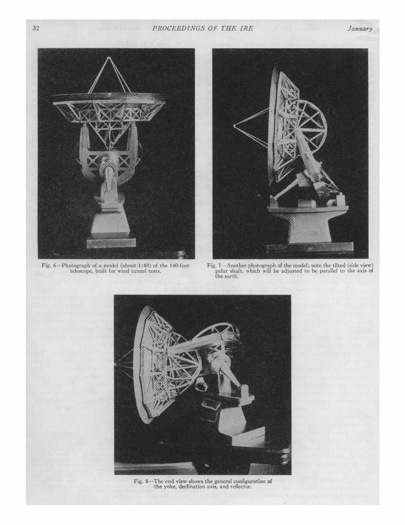
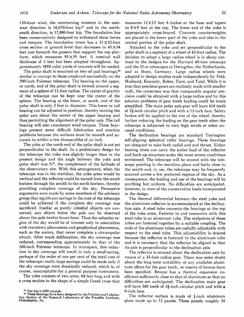
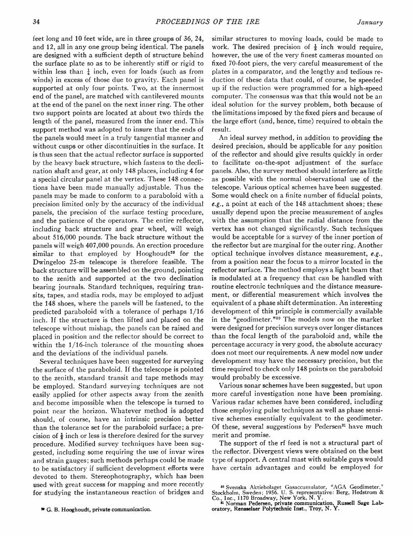
Fig. 9, which are photographs of a model constructed fortest purposes. The foundation will be made of concrete.The polar shaft rotates on two bearings that are adjust-able to permit alignment of the polar axis of the tele-scope with the axis of the earth. A yoke and a drive gearof 42-foot radius are attached to the north, or upper,end of the polar shaft. At the upper ends of the yoke aretwo bearings for the declination shaft; these are movableto permit adjustment of the declination axis to be per-pendicular to the polar axis. Steel is contemplated for allmetal up to the declination axis. The reflector, support-ing structure and 35-foot radius wheel for the declina-tion gear, are made of aluminum.The foundation stands about 40 feet high, not includ-
ing the subsurface portion that extends down to therock strata 30 feet below the existing ground level. Thelarge volume inside the foundation will be utilized forthe control and observing station and for housing trans-formers, motors, pumps and similar ancillary equip-ment. The telescope proper will weigh approximately2000 tons. In addition, for the survival condition of a
24 N. L. Ashton, 820 Park Road, Iowa City, Iowa; Prof. Ashtondesigned the 50-foot parabolic reflector that was built for the NavalResearch Laboratory by the Collins Radio Company.
25 This ad hoc advising group consists of T. C. Kavanagh, chair-man, P. P. Bijlaard, N. A. Christensen, A. M. Freudenthal, J. 0.Silvey, D. Lindorff, E. J. Poitras, B. H. Rule, F. T. Haddock, E. F.McClain, and H. E. Tatel. J. G. Bolton, who was serving on the adhoc group and also on the IAU Advisory Committee for the entireproject, resigned early in 1957, because of the press of his own radioastronomy affairs. Although there have been sharp differences ofopinion on many points, resolution has been possible and the grouphas worked effectively and efficiently with Ashton.
" N. L. Ashton, in preparation.
1958 31
PROCEEDINGS OF THE IRE
Fig. 6-Photograph of a model (about 1:60) of the 140-foottelescope, built for winid tunnel tests.
Fig. 7-Another photograph of the model; note the tilted (side view)polar shaft, which will be adjusted to be parallel to the axis ofthe earth.
Fig. 8-The end view shows the general configuration ofthe yoke, declination axis, and reflector.
32 January
Emberson and Ashton: Telescope for the National Radio Astronomy Observatory
120-knot wind, the overturning moment in the east-west direction is 16,670-foot kip"7 and in the north-south direction, is 17,880-foot kip. The foundation hasbeen conservatively designed to withstand these forcesand torques. The foundation tower has a 51X52-footcross section at ground level that decreases to 45X34feet just beneath the gussets that support the top plat-form, which measures 95 X39 feet. A nominal wallthickness of 3 feet has been adopted throughout. Ap-proximately 2850 cubic yards of concrete will be needed.The polar shaft is mounted on two oil pad bearings,28
similar in concept to those employed successfully on the200-inch Palomar telescope. The bearing on the upper,or north, end of the polar shaft is formed around a seg-ment of a sphere of 11-foot radius. The center of gravityof the telescope can be kept near the center of thesphere. The bearing at the lower, or south, end of thepolar shaft is only 5 feet in diameter. This lower or tailbearing can be adjusted in position, thereby moving thepolar axis about the center of the upper bearing andthus permitting the alignment of the polar axis. The tailbearing will also counteract wind torques. These bear-ings present some difficult fabrication and erectionproblems because the surfaces must be smooth and ac-curate to within a few thousandths of an inch.The yoke at the north end of the polar shaft is not set
perpendicular to the shaft. In a preliminary design forthe telescope the yoke was slightly longer than in thepresent design and the angle between the yoke andpolar shaft was 510, the complement of the latitude ofthe observatory site. With this arrangement, when thetelescope was in the meridian, the yoke arms would bevertical and the reflector could be turned from the southhorizon through the zenith to the north horizon, therebyproviding complete coverage of the sky. Persuasivearguments were made by some members of the advisorygroup that significant savings in the cost of the telescopecould be achieved if the complete sky coverage wassacrificed. Insofar as purely celestial objects are con-cerned, any object below the pole can be observedabove the pole twelve hours later. Thus the subpolar re-gion of the sky would be of interest only in associationwith transitory phenomena and geophysical phenomena,such as the aurora, that never complete a circumpolarcircuit. After much deliberation, the sky coverage wasreduced, corresponding approximately to that of the200-inch Palomar telescope. In retrospect, this reduc-tion in sky coverage will result in only a small saving,perhaps of the order of one per cent of the total cost ofthe telescope; really large savings could be made only ifthe sky coverage were drastically reduced, which is, ofcourse, unacceptable for a general purpose instrument.The yoke consists of two arms, 64 feet long and with
a cross section in the shape of a simple Greek cross that
27 One kip= 1000 pounds.28 These bearings have been designed by the Friction and Lubrica-
tion Section of the Research Laboratory of the Franklin Institute,Philadelphia, Pa.
measures 12 X 12 feet 6 inches at the base and tapersto 8 X9 feet at the top. The lower end of the yoke isappropriately cross-braced. Concrete counterweightsare placed in the lower part of the yoke and also in thecentral portion of the polar shaft.Attached to the yoke and set perpendicular to the
polar shaft is a segment of a wheel of 42-foot radius. Thedecision to adopt a large radius wheel is in sharp con-trast to the designs for the Harvard 60-foot telescopeand the 25-m telescopes at Dwingeloo, the Netherlands,and at Bonn, Germany. Large radius wheels wereadopted in design studies made independently by Feld,Husband, Kennedy, Reber, Tuve, and Tatel. While it istrue that precision gears are routinely made with smallerradii, the consensus was that comparable angular pre-cision could be obtained with a large radius and by thissolution problems of gear tooth loading could be muchsimplified. The main polar axis gear will have 618 teethof 32-inch circular pitch and with a 12-inch face. Safetybrakes will be applied to the rim of the wheel, therebyfurther reducing the loading on the gear teeth when thetelescope is subjected to very high winds or other un-usual conditions.The declination bearings are standard Torrington
self-aligning spherical roller bearings. These bearingsare designed to take both radial and end thrust. Eitherbearing alone can carry the entire load of the reflectorand back-up structure under the most severe conditionsenvisioned. The telescope will be stowed with the tele-scope pointing in the meridian plane and fairly close tothe zenith and, in use, the telescope may be frequentlyscanned across a few preferred regions of the sky. As aconsequence, the loading and use of the bearings will beanything but uniform. No difficulties are anticipated,however, in view of the conservative loads incorporatedin the design.The thermal differential between the steel yoke and
the aluminum reflector is accommodated at the declina-tion axis. A steel tube connects the bearings at the topof the yoke arms. Exterior to and concentric with thissteel tube is an aluminum tube. The midpoints of thesetubes are fastened together by a suitable coupling. Theends of the aluminum tubes are radially adjustable withrespect to the steel tube. This adjustability is desiredbecause the reflector is fastened to the aluminum tubeand it is necessary that the reflector be aligned so thatits axis is perpendicular to the declination axis.The reflector is rotated about the declination axis by
means of a 35-foot radius gear. There was some doubtabout the long-term suitability of any available alumi-num alloys for the gear teeth, so inserts of bronze havebeen specified. Bronze has a thermal expansion co-efficient sufficiently close to that of aluminum so that nodifficulties are anticipated. The declination main gearwill have 360 teeth of 32-inch circular pitch and with a9-inch face.The reflector surface is made of "-inch aluminum
plate made up in 72 panels. These panels, roughly 20
331958
PROCEEDINGS OF THE IRE
feet long and 10 feet wide, are in three groups of 36, 24,and 12, all in any one group being identical. The panelsare designed with a sufficient depth of structure behindthe surface plate so as to be inherently stiff or rigid towithin less than 4 inch, even for loads (such as fromwinds) in excess of those due to gravity. Each panel issupported at only four points. Two, at the innermostend of the panel, are matched with cantilevered mountsat the end of the panel on the next inner ring. The othertwo support points are located at about two thirds thelength of the panel, measured from the inner end. Thissupport method was adopted to insure that the ends ofthe panels would meet in a truly tangential manner andwithout cusps or other discontinuities in the surface. Itis thus seen that the actual reflector surface is supportedby the heavy back structure, which fastens to the decli-nation shaft and gear, at only 148 places, including 4 fora special circular panel at the vertex. These 148 connec-tions have been made manually adjustable. Thus thepanels may be made to conform to a paraboloid with aprecision limited only by the accuracy of the individualpanels, the precision of the surface testing procedure,and the patience of the operators. The entire reflector,including back structure and gear wheel, will weighabout 516,000 pounds. The back structure without thepanels will weigh 407,000 pounds. An erection proceduresimilar to that employed by Hooghoudt29 for theDwingeloo 25-m telescope is therefore feasible. Theback structure will be assembled on the ground, pointingto the zenith and supported at the two declinationbearing journals. Standard techniques, requiring tran-sits, tapes, and stadia rods, may be employed to adjustthe 148 shoes, where the panels will be fastened, to thepredicted paraboloid with a tolerance of perhaps 1/16inch. If the structure is then lifted and placed on thetelescope without mishap, the panels can be raised andplaced in position and the reflector should be correct towithin the 1/16-inch tolerance of the mounting shoesand the deviations of the individual panels.
Several techniques have been suggested for surveyingthe surface of the paraboloid. If the telescope is pointedto the zenith, standard transit and tape methods maybe employed. Standard surveying techniques are noteasily applied for other aspects away from the zenithand become impossible when the telescope is turned topoint near the horizon. Whatever method is adoptedshould, of course, have an intrinsic precision betterthan the tolerance set for the paraboloid surface; a pre-cision of 8 inch or less is therefore desired for the surveyprocedure. Modified survey techniques have been sug-gested, including some requiring the use of invar wiresand strain gauges; such methods perhaps could be madeto be satisfactory if sufficient development efforts weredevoted to them. Stereophotography, which has beenused with great success for mapping and more recentlyfor studying the instantaneous reaction of bridges and
" G. B. Hooghoudt, private communication.
similar structures to moving loads, could be made towork. The desired precision of ' inch would require,however, the use of the very finest cameras mounted onfixed 70-foot piers, the very careful measurement of theplates in a comparator, and the lengthy and tedious re-duction of these data that could, of course, be speededup if the reduction were programmed for a high-speedcomputer. The consensus was that this would not be anideal solution for the survey problem, both because ofthe limitations imposed by the fixed piers and because ofthe large effort (and, hence, time) required to obtain theresult.An ideal survey method, in additionl to providing the
desired precision, should be applicable for any positionof the reflector and should give results quickly in orderto facilitate on-the-spot adjustment of the surfacepanels. Also, the survey method should interfere as littleas possible with the normal observational use of thetelescope. Various optical schemes have been suggested.Some would check on a finite number of fiducial points,e.g., a point at each of the 148 attachment shoes; theseusually depend upon the precise measurement of angleswith the assumption that the radial distance from thevertex has not changed significantly. Such techniqueswould be acceptable for a survey of the inner portion ofthe reflector but are marginal for the outer ring. Anotheroptical technique involves distance measurement, e.g.,from a position near the focus to a mirror located in thereflector surface. The method employs a light beam thatis modulated at a frequency that can be handled withroutine electronic techniques and the distance measure-ment, or differential measurement which involves theequivalent of a phase shift determination. An interestingdevelopment of this principle is commercially availablein the "geodimeter."30 The models now on the marketwere designed for precision surveys over longer distancesthan the focal length of the paraboloid and, while thepercentage accuracy is very good, the absolute accuracydoes not meet our requirements. A new model now underdevelopment may have the necessary precision, but thetime required to check only 148 points on the paraboloidwould probably be excessive.
Various sonar schemes have been suggested, but uponmore careful investigation none have been promising.Various radar schemes have been considered, includingthose employing pulse techniques as well as phase sensi-tive schemes essentially equivalent to the geodimeter.Of these, several suggestions by Pedersen3" have muchmerit and promise.The support of the rf feed is not a structural part of
the reflector. Divergent views were obtained on the besttype of support. A central mast with suitable guys wouldhave certain advantages and could be employed for
30 Svenska Aktiebolaget Gasaccumulator, "AGA Geodimeter,"Stockholm, Sweden; 1956. U. S. representative: Berg, Hedstrom &Co., Inc., 1170 Broadway, New York, N. Y.
31 Norman Pedersen, private communication, Russell Sage Lab-oratory, Rensselaer Polytechnic Inst., Troy, N. Y.
34 January
Findlay: Noise Levels at the National Radio Astronomy Observatory
supporting dipole feeds and special types of invertedhorns. Bipods with guys, tripods, and quadripods ap-pear generally to offer more flexibility. A quadripod willbe built for the 140-foot telescope; this decision wasbased on consideration of stability, symmetry, andadaptability to a variety of feeds and receiver compo-nents. If desired at a later date, another type of feedsupport may be easily substituted.A great deal of thought was given to the side-lobe and
back-lobe effects of the feed support. In general practice,side lobes may be 20 db down from the central beam andback lobes may be 30 to 40 db down. For many installa-tions, e.g., in an aircraft or part way up the mast of aship, there are so many other nearby objects to increasespurious side lobes that attempts to refine the feed sup-port and reduce the inherent side lobes and back lobes
are not warranted. This situation does not pertain tolarge radio astronomy telescopes. If the 140-foot tele-scope will have 20-db side lobes, these will have ap-preciable directive gain. It is therefore desirable to re-duce the side lobes and back lobes to levels below thoseusually accepted. Studies of this problem have beenplanned, the results of which will be reported later.
ACKNOWLEDGMENTMany individuals have contributed to the work re-
ported herein, including those named in the text andreferences, and J. W. Findlay and D. S. Heeschen of theAUI staff. All share credit for bringing the radio tele-scope program to its present status, and we express ourthanks and appreciation to them and to the NSF staffmembers associated with the work.
Noise Levels at the National RadioAstronomy Observatory*
J. W. FINDLAYt
Summary-The measurements which have been made of thefield strengths of radio signals received at the Green Bank site of theNational Radio Astronomy Observatory are described. The site isrelatively free from interference and the measures which are beingadopted to preserve its radio quietness are discussed.
INTRODUCTIONT HE PURPOSE of this paper is to discuss briefly
the levels of man-made noise which exist at thelocation which has been chosen as the site of the
National Radio Astronomy Observatory.The smallest radio signals which can be detected in
radio astronomy are at present determined mainly bythe noise figures, stability, and bandwidths of receiversand by the sizes of the antenna systems used. In thefuture, however, it is reasonable to foresee that the usein receivers of low noise crystals, traveling wave tubes,or masers, and the development of larger antennas, willbring about the state of affairs in which the limit of use-fulness of a radio telescope will be set by the noise at theobserving site. Part of this noise comes from man-madesources. A part which will also become more importantas better receivers are developed, comes from radiationfrom the ground and surrounding objects entering thereceiving system of the radio telescope. This lattersource of noise is not considered in the present paper,
* Original manuscript received by the IRE, November 11, 1957.t Associated Universities, Inc., New York, N. Y.
since current receiver techniques are not yet so good asto make it a limiting factor in the performance of aradio telescope. However, fairly soon it will be an im-portant factor to consider in the design of future radiotelescopes. The present paper discusses first, the approx-imate levels of the smallest signals which have been de-tected so far in radio astronomy, next, the levels of noiseat the site of the National Radio Astronomy Observa-tory are described, and last, the measures which have beentaken to reduce to a minimum any future deteriorationof the site are discussed.
THE SIGNALS RECEIVED IN RADIO ASTRONOMYA survey of the results of various observers over a
wide range of frequencies allows of an order of magni-tude to be stated for the lower limit of the flux densitywhich is detectable with present day techniques and in-struments. This minimum detectable flux is about 10-25watts per square meter in 1 cps bandwidth. This is, ofcourse, a figure which is right only to an order of magni-tude, but it generally describes the results for frequen-cies from about 50 mc up to 10 kmc. Improvements ofan order of magnitude at least are to be expected whenresults from larger antennas and from new receiver tech-niques are available.However, the present figure illustrates the magnitude
of the problem of avoiding interference from man-made
1958 35