the tesla linear collider
TRANSCRIPT

The TESLA Linear Collider
Winfried Decking (DESY)for the TESLA Collaboration

Outline• Project Overview• Highlights 2000/2001
– Publication of the TDR– Cavity R&D– TTF Operation
• A0 and PITZ• TESLA Beam Dynamics• Site Investigation (PFV)• Summary

TESLA – A Quick Overview
• Superconducting 1.3 GHz cavities– small wakefields– high wall-plug power to beam power
efficiency– long beam pulse with large inter-bunch
spacing
• 500-800 GeV c.m. • Luminosity 3.4-5.8×1034 cm-2s-1
• Proposed by an international collaboration (42 institutes, 10 countries) on a site at DESY in Hamburg/Germany

Layout

Positron Source
• γ produced by high energy electron beam in undulator placed before the IP
• Thin target converts the γ to positrons

Electron Sources

Damping Ring
• 17 km long to accommodate TESLA bunch train
• Looks unconventional, but major ‘new’ issue is space charge, cured by local coupling
• Needs a 20 ns rise/fall-time injection kicker system

Beam Delivery and Interaction Region
• 1st IP has no crossing angle
• FFTB style layout

TESLA ParametersSite length km 33 # of cavities 21024 Energy (c.m.) GeV 500 800 e+ e- e- e- γγ e+ e- Repetition Rate Hz 5 4 Beam pulse length µs 950 860 # of bunches 2820 4886 Bunch spacing ns 337 176 Charge per bunch 2e10 1.4e10 Beam size at IP nm 553 / 5 157 / 5 391 /2.8 Bunch length at IP mm 0.3 Beamstrahlung % 3.2 2.0 -- 4.3 Luminosity 1034 cm-2s-1 3.4 0.47 0.6 5.8 Total beam power MW 22.6 34 Linac electric power MW 97 150 Accelerating gradient MV/m 23.4 35 # of klystrons MW 584 1240
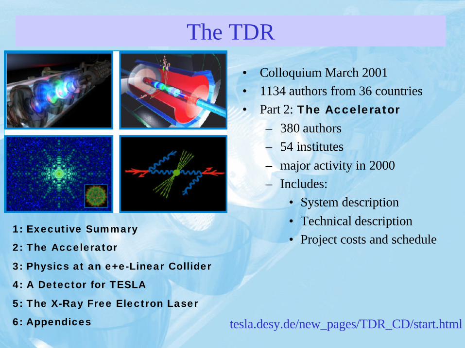
The TDR
• Colloquium March 2001 • 1134 authors from 36 countries• Part 2: The Accelerator
– 380 authors– 54 institutes– major activity in 2000– Includes:
• System description• Technical description• Project costs and schedule
1: Executive Summary
2: The Accelerator
3: Physics at an e+e-Linear Collider
4: A Detector for TESLA
5: The X-Ray Free Electron Laser
6: Appendices tesla.desy.de/new_pages/TDR_CD/start.html

Highlights Cavity R&D
• Standard 9-cell cavities >25 MV/m • Gradient record >42 MV/m in electro polished
seamless single-cell NB cavity• Gradient > 40 MV/m in seamless single-cell NBCu
cavity and in electro polished single-cell NB cavity• Gradient 32 MV/m in electro polished 9-cell NB cavity

Standard Cavity Preparation• Niobium sheets (RRR=300) are eddy-current scaned to avoid foreign material inclusions
• Industrial production of full nine-cell cavities:
– Deep-drawing of subunits (half-cells, etc. ) from niobium sheets
– Electron-beam welding according to detailed specification
• 800 °C high temperature treatment stress anneals the Nb and removeshydrogen
• 1400 °C high temperature treatment with titanium getter layer to increase the thermal conductivity (RRR=500)
• Chemical etching to remove damage layer and titanium getter layer
• High pressure water rinsing as final treatment to avoid particle contamination

What do we get?
Excitation Curve Cavities Latest Production

Some Statistics Mode analysis (single cell gradient of 9-cell cavity)
Knwon defects can explain tails
Improvements 1st 2nd and 3rd production

So – Where are we?
• 3 production series of 9-cell cavities with ≈ 30 cavities each
• Improvements for series 2 and 3:– welding technique– eddy current scans of every
Nb-sheet to detect imperfections
• 5 modules built so far, 3 tested with beam
• 4 (+1) more modules to be built– one with electropolished cavities
0
5
10
15
20
25
30
5 6 2* 7 8
Module #
Eacc [
MV
/m]
Ele
ctr
op
olish
ed
Cavit
ies

The Road to 35 MV/m
Quench limit Improve surface quality of cavities through electropolishing
Lorentz forces / detuning
•Cavity stiffening
•Active tuning with piezoelectric tuner
Field emission Cleaning, high power conditioning

Electropolishing (KEK, CERN/CEA/DESY)

Electropolishing Results – Single Cell
Sample of single cell NB cavities Same 6 cavities after BCP resp. EP
12 cavities > 40 MV/m worldwide, 10 EP, 2BCP

Electropolishing Results - 9-cell Cavities
• Very promising result on 1st EP 9-cell cavity
• Goal:
– Improve EP procedure
– Built a module out of EP cavities only by 2003
• Infrastructure for 9-cell EP built at DESY, commissioning starts March
• Module 6 will be made of EP cavities only, test in 2003
EP at Nomura Plating and KEK
measured at DESY
9 cell NB cavity

TESLA Test Facility
–First SASE at 109 nm February 2000
–Saturation at 100 nm September 2001

Future Module Tests at TTF1 and 2
• Full beam-loading with high gradient March/April 02• Superstructure without/with beam July-September 02• Reconstruction TTF1 to TTF2 May 02 – June 03• Module 1* (25 MV/m) July-October 02• Module 3, 4, 5 (all around 25 MV/m)
– RF tests Feb.-April 03– Beam operation start July 03
• Module 6 (electro-polished)– On module test stand End of 2003– In TTF2 2004

TESLA RF Distribution System
286 RF Units per LINAC :• 10,296 Cavities• 858 Cryomodules• 286 Klystrons
KRF Unit : 1 klystron
3 cryomodules36 cavities

Multibeam Klystron
Acceptance test:
116 kV, 10 MW, 1.5 ms, 5 Hz, η=65%
Typical operation at TTF in 2001:
95-100 kV, 3-4 MW, 1.5 ms, 1 Hz

Beam Loading Compensation
Full TESLA current
Performance of low level RF control

Lorentz Force Detuning

Superstructure

TESLA HOM Model
all modes damped below 1×10⁵, but …
36 cavity average, 0.1% energy spread36 cavity average, 0.1% energy spread

Higher Order Mode Measurements with Beam

Beam at 2.6 GHzHOM at 2.585 GHz
HOM Pickup Signal
frequency domain time domain
35 µsbeam
Decay time ⇒ Q = 106
High-Q HOM in the 3rd Passband•Measured with intensity modulated beam with position offset
•Detected in HOM coupler and broadband BPM

ϕ + 30o
f / GHz
upstream coupler
downstream coupler(without FMC)
upstream coupler(mirror transformation)
fc(H11) fc(E01)
Damping the 2.585 GHz mode
DESY typeHOM coupler
One coupler is"mirrored"
Coupling depends on frequency and polarization

Flat Beam Experiment at A0/FERMILAB
Maximum measured emittance ratio: 50/1
Extract flat beam from RF-gun through combination of non-zero solenoid field on cathode surface and skew quad beam transformer

Photo Injector Test Stand in Zeuthen
First photo electrons January 2002

‘Banana’ Effect – Beam-Beam Simulation
Nominal TESLA Beam Parameters +
y-z correlation (equivalent to few % projected emittance growth)
Beam centroids head on
•Instability driven by vertical beam profile distortion
•Strong for high disruption
•Distortion caused by transverse wakefields and quad offset – only a few percent emittance growth
•Tuning can remove static part

‘Banana’ Effect
ΤDR Parametersσs= 300 µm βx= 15 mmβy= 0.4 mm
Bunch length shortenedσs= 150 µmβx= 20 mmβy= 0.3 mm
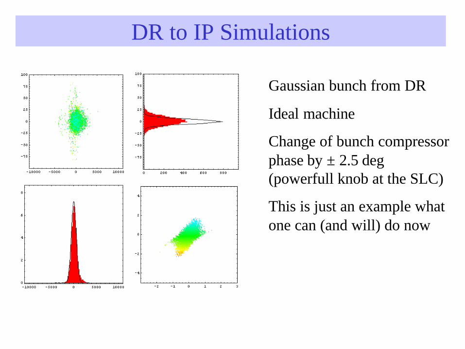
DR to IP Simulations
Gaussian bunch from DR
Ideal machine
Change of bunch compressor phase by ± 2.5 deg (powerfull knob at the SLC)
This is just an example what one can (and will) do now

Planfeststellungsverfahren (PFV)
• Procedure to obtain legal approval to built TESLA on the specific site (not the political approval)
• Investigate:– Impact on Environment– Impact on Humans– Impact on Ecology– Safety issues – ...
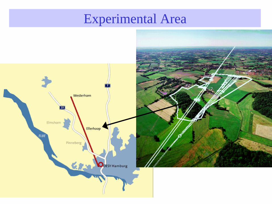
Experimental Area

DESY Site and Cryo-Hall

Church of Rellingen

PFV
• Group of approximately 30 people (DESY and external contractors) works on:– Compiling the relevant informtion– Provide information to the public
• 3-D CAD heavely used for planing and communicating the concept
• Information publically available on the WWWhttp://www.desy.de/tesla-planung/
• This is almost like pooring the concrete

Summary• 9 years of R&D on TESLA culminated in the
publication of the TDR March 2001• The technology for a 500 GeV collider is at hand• Cavity R&D program continues with the goal to reach
the ultimate performance limit of SC cavities• TESLA collaboration has initiated the formal approval
procedure to built a linear collider in Hamburg• Since Snowmass 2001 a very intense international
discussion has started on how, who, where, what, when… and will continue during LC02
Thanks to all colleagues for providing me with information.