the tesla secret free energy generation the tesla generator - talking
TRANSCRIPT
THE TESLA SECRET
FREE ENERGY GENERATION
THE TESLA GENERATORThis document normally costs $49.00 and is spouted as “Plans to
produce FREE ENERGY for $100.00”
It contains a lot of history but the actual implementation of achieving
FREE ENERGY in any worthwhile amount is pure FANTASY.
No-where does this document show a working model of anything
worthwhile and it has been released on TALKING ELECTRONICS website
to save anyone wasting their time, money and effort in trying to generate
anything from the “ether.”
The “generator” shown in a video on this site: http://slnk.me/1026t
gets its energy from the RF produced by the hundreds of TV transmitters,
cell-phones and towers.
You have to realise the producers of this article have mixed truth with
fiction with hypothesis, fantasy and probability, and no functional device
has been presented.
If anything remotely feasible is invented, it will be on YouTube.
Colin Mitchell
TALKING ELECTRONICS
18-9-2011
FREE ENERGY GENERATION
THANK YOU for allowing us to offer you the perfect solution for a
free energy lifestyle. Your choices are valuable to us and your care
for the environment can only bring us Joy. We appreciate your trust in
our product and we are confident that you will be more than satisfied.
In the next few moments we will introduce you to one of the greatest
scientists in history and guide you into building your own Tesla
Generator which will change your life forever.
The Tesla Secret Team
2
Table of Contents
Introduction................................................................................................................... 6
Chapter 1 ....................................................................................................................... 8
The Increasing Need for Energy Conservation ............................................................ 8
What Is Energy Conservation? ................................................................................ 8
Burning Fossil Fuels ............................................................................................. 9
Hydroelectric Energy Generation........................................................................ 10
Nuclear Power Generation ................................................................................. 11
Energy Conservation Reduces Power Consumption............................................... 13
Alternative Energy Production and Energy Conservation........................................ 13
Solar Power........................................................................................................ 14
Wind Power Generation...................................................................................... 15
Geothermal Power Generation............................................................................ 16
Ocean Wave Power Generation.......................................................................... 17
Another Alternative ................................................................................................ 18
Chapter 2..................................................................................................................... 19
A Look into the Person of Nikola Tesla ...................................................................... 19
Tesla - The Formation of Genius............................................................................ 19
Sickness and Disability .......................................................................................... 20
Further Changes- Life Abroad ............................................................................... 21
Working with Edison ................................................................................................ 22
Tesla Becomes an American Citizen and the War of Currents ............................... 23
The Move to Colorado Springs .............................................................................. 24
The Wardenclyffe Years ......................................................................................... 25
3
Tesla's Final Years ................................................................................................. 27
Chapter 3..................................................................................................................... 29
Tesla's Inspiration for Radiant Energy Generation ..................................................... 29
Tesla's Introduction to Radiant Energy ................................................................... 29
What Did the Blue Spike Phenomenon Mean?....................................................... 30
Tesla Begins Experimentation ................................................................................ 31
The Conclusion of Tesla's Experiments.................................................................. 31
Further Experimentation with Radiant Energy......................................................... 32
Chapter 4..................................................................................................................... 34
Tesla's Radiant Energy Device ................................................................................. 34
Defining the Term "Radiant Energy" ....................................................................... 35
How Is Radiant Energy Created? ........................................................................... 36
The Argument for and Against "Free" Energy......................................................... 36
The Argument Against......................................................................................... 37
The Argument For .............................................................................................. 37
How Do You Harness Radiant Energy?.................................................................. 38
Building the Antenna.............................................................................................. 38
Safety Precautions................................................................................................. 41
Designs.................................................................................................................. 41
Chapter 5..................................................................................................................... 45
The Tesla Coil ........................................................................................................... 45
What Is a Tesla Coil?............................................................................................. 45
How Does the Coil Work In A Self-Sustaining Energy System? .............................. 47
How to build a real Tesla Coil that can generate lightning..........................................49
The low leakage Capacitor........................................................................................ 53
4
Operating the generator ..............................................................................................54
Tuning ........................................................................................................................55
Experiments................................................................................................................57
So how does it work?..................................................................................................58
Construction of the capacitor.......................................................................................59
Chapter 6..................................................................................................................... 67
The Dynamo-Electric Machine................................................................................... 67
What Is the Dynamo-Electric Machine?.................................................................. 67
Variations on the Faraday Design .......................................................................... 68
Chapter 7..................................................................................................................... 71
The Tesla Turbine.................................................................................................. 71
Understanding the Differences in Turbine Designs ................................................. 71
Example of how to build a Tesla Disc Turbine......................................................... 76
Making the parts .................................................................................................... 77
Testing ................................................................................................................... 81
Conclusion.................................................................................................................... 88
Appendix ...................................................................................................................... 89
The Tesla Legacy....................................................................................................... 107
5
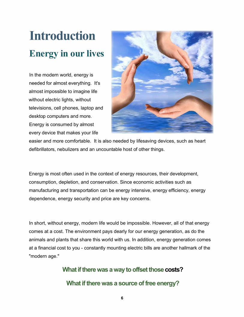
IntroductionEnergy in our lives
In the modern world, energy is
needed for almost everything. It's
almost impossible to imagine life
without electric lights, without
televisions, cell phones, laptop and
desktop computers and more.
Energy is consumed by almost
every device that makes your life
easier and more comfortable. It is also needed by lifesaving devices, such as heart
defibrillators, nebulizers and an uncountable host of other things.
Energy is most often used in the context of energy resources, their development,
consumption, depletion, and conservation. Since economic activities such as
manufacturing and transportation can be energy intensive, energy efficiency, energy
dependence, energy security and price are key concerns.
In short, without energy, modern life would be impossible. However, all of that energy
comes at a cost. The environment pays dearly for our energy generation, as do the
animals and plants that share this world with us. In addition, energy generation comes
at a financial cost to you - constantly mounting electric bills are another hallmark of the
"modern age."
What if there was a way to offset those costs?
What if there was a source of free energy?
6
The words "free energy" have been bandied about so much in recent years that you
have every right to look at the subject with some skepticism. However, the fact remains
that, thanks to one man's amazing contributions to science and technology, free energy
can be a reality for you.
Who was this man?
What indention might give you the ability to generate energy at no cost?
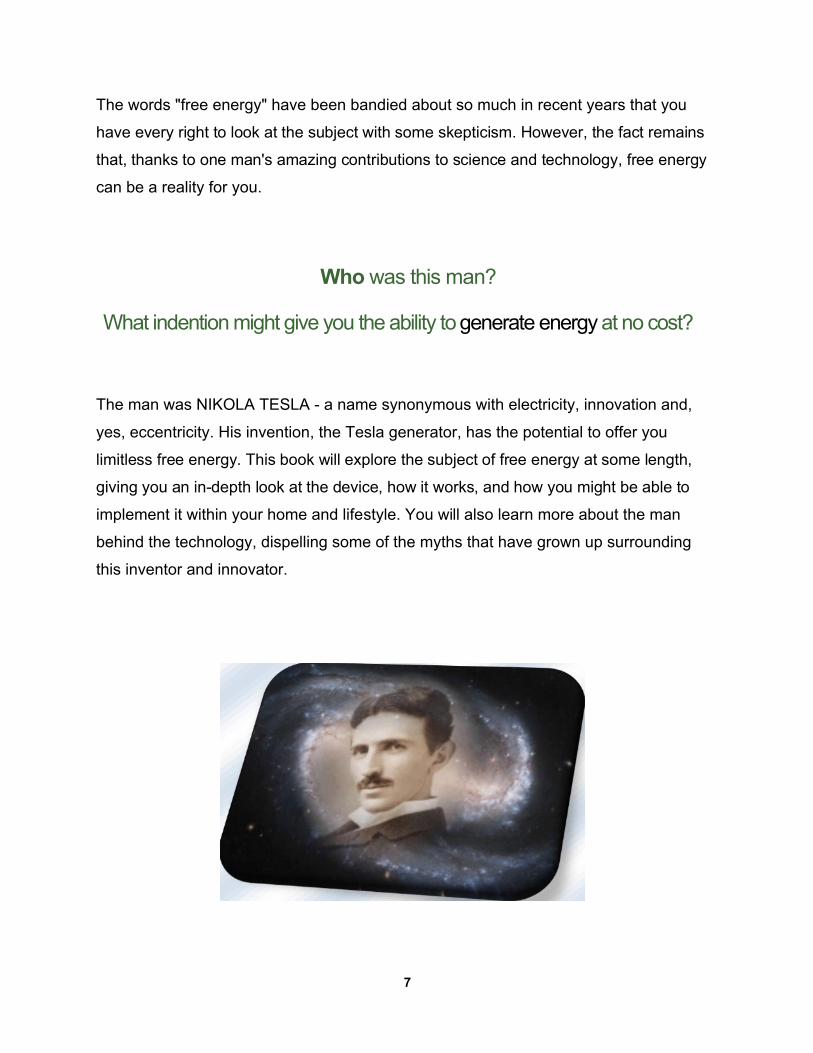
The man was NIKOLA TESLA - a name synonymous with electricity, innovation and,
yes, eccentricity. His invention, the Tesla generator, has the potential to offer you
limitless free energy. This book will explore the subject of free energy at some length,
giving you an in-depth look at the device, how it works, and how you might be able to
implement it within your home and lifestyle. You will also learn more about the man
behind the technology, dispelling some of the myths that have grown up surrounding
this inventor and innovator.
7
Chapter 1
The Increasing Need for Energy Conservation
Before we delve into the character and inventions of Nikola Tesla, a few things need to
be said about the importance and increasing need for energy conservation. While this
is certainly a hot topic in today's modern world, many people are not fully aware of just
how dire the situation truly is. In this chapter, you will learn a bit more about energy
conservation, and why it is so important.
What Is Energy Conservation?Conserving energy can be defined as anything that reduces the amount of electricity
produced through traditional methods and used by consumers or businesses. The
"standard" means of producing electricity are harmful to the environment, use short-
lived natural resources that are not replenished and come at a high cost to humankind.
There are several ways in which electricity is generated in the modern world.
• Burning fossil fuels, such as coal, petroleum or natural gas
• Hydroelectric generation systems that harness the power of moving water
• Nuclear reactors that create electricity by splitting the atom
Each of these has a considerable number of drawbacks that affect the environment, the
quality of life for human beings, and even the sustainability of the technology itself.
Below, you will find a few of these drawbacks to help highlight the need for energy
conservation.
8

Burning Fossil Fuels
A wide range of different fossil fuels can be burned in the process of creating electricity.
COAL is one of the most common fuels used, though natural gas and petroleum are
also used. There are two main problems with these systems. The first problem is the
fact that burning these fuels creates an immense amount of pollution. In addition, the
harvesting methods used to obtain these fuels from the earth are harmful in and of
themselves.
Besides, these are nonrenewable natural resources. The earth possesses only a finite
amount of coal, oil and natural gas. When those sources are gone, it will be millions of
years before there are any more available. This means that any method of generating
electricity that relies on these methods cannot be sustained indefinitely.
9
Many people surmise that this is not truly an issue. After all, there should be enough
fossil fuels left in the earth that their depletion will be a problem for some future
generation, not for the here and now.
However, this is misleading. In fact, many scientists are beginning to suspect that we
will run out of these resources within the next few decades. That means that many of
the people living right now will see the end of these resources.
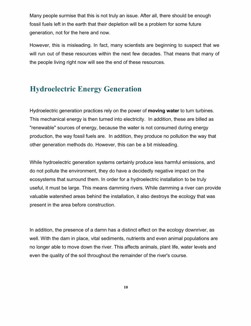
Hydroelectric Energy Generation
Hydroelectric generation practices rely on the power of moving water to turn turbines.
This mechanical energy is then turned into electricity. In addition, these are billed as
"renewable" sources of energy, because the water is not consumed during energy
production, the way fossil fuels are. In addition, they produce no pollution the way that
other generation methods do. However, this can be a bit misleading.
While hydroelectric generation systems certainly produce less harmful emissions, and
do not pollute the environment, they do have a decidedly negative impact on the
ecosystems that surround them. In order for a hydroelectric installation to be truly
useful, it must be large. This means damming rivers. While damming a river can provide
valuable watershed areas behind the installation, it also destroys the ecology that was
present in the area before construction.
In addition, the presence of a damn has a distinct effect on the ecology downriver, as
well. With the dam in place, vital sediments, nutrients and even animal populations are
no longer able to move down the river. This affects animals, plant life, water levels and
even the quality of the soil throughout the remainder of the river's course.
10
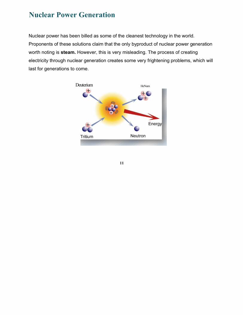
Nuclear Power Generation
Nuclear power has been billed as some of the cleanest technology in the world.
Proponents of these solutions claim that the only byproduct of nuclear power generation
worth noting is steam. However, this is very misleading. The process of creating
electricity through nuclear generation creates some very frightening problems, which will
last for generations to come.
Deuterium HeNum
11
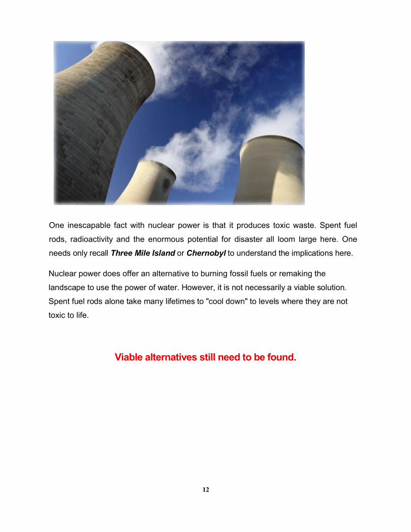
One inescapable fact with nuclear power is that it produces toxic waste. Spent fuel
rods, radioactivity and the enormous potential for disaster all loom large here. One
needs only recall Three Mile Island or Chernobyl to understand the implications here.
Nuclear power does offer an alternative to burning fossil fuels or remaking the
landscape to use the power of water. However, it is not necessarily a viable solution.
Spent fuel rods alone take many lifetimes to "cool down" to levels where they are not
toxic to life.
Viable alternatives still need to be found.
12
Energy Conservation Reduces
Power Consumption
Energy conservation is an essential
consideration for anyone living in the
modern world. The more energy that can
be conserved or produced through
alternative, renewable methods, the lower
the load placed on traditional electricity
generation stations.
This means that the more energy that is conserved or created through an alternate
method, the less coal, petroleum or oil needs to be burned. The more energy that is
conserved, the less need there is for new hydroelectric installations or new nuclear
reactors.
Energy must be conserved, and new sources of energy generation brought online as
quickly as possible. Of course, there are several alternative sources of energy currently
available to consumers.
Alternative Energy Production and Energy Conservation
Several alternative options exist for those who want to conserve as much energy as
possible, or even produce enough electricity to remove themselves from the equation
completely. Most of these technologies have been around for a number of years,
though they have been refined considerably during that time. These sources include:
13
El FREE ENERGY GENERATION
• Solar power generation
• Wind power generation
• Geothermal power generation
• Ocean wave power generation
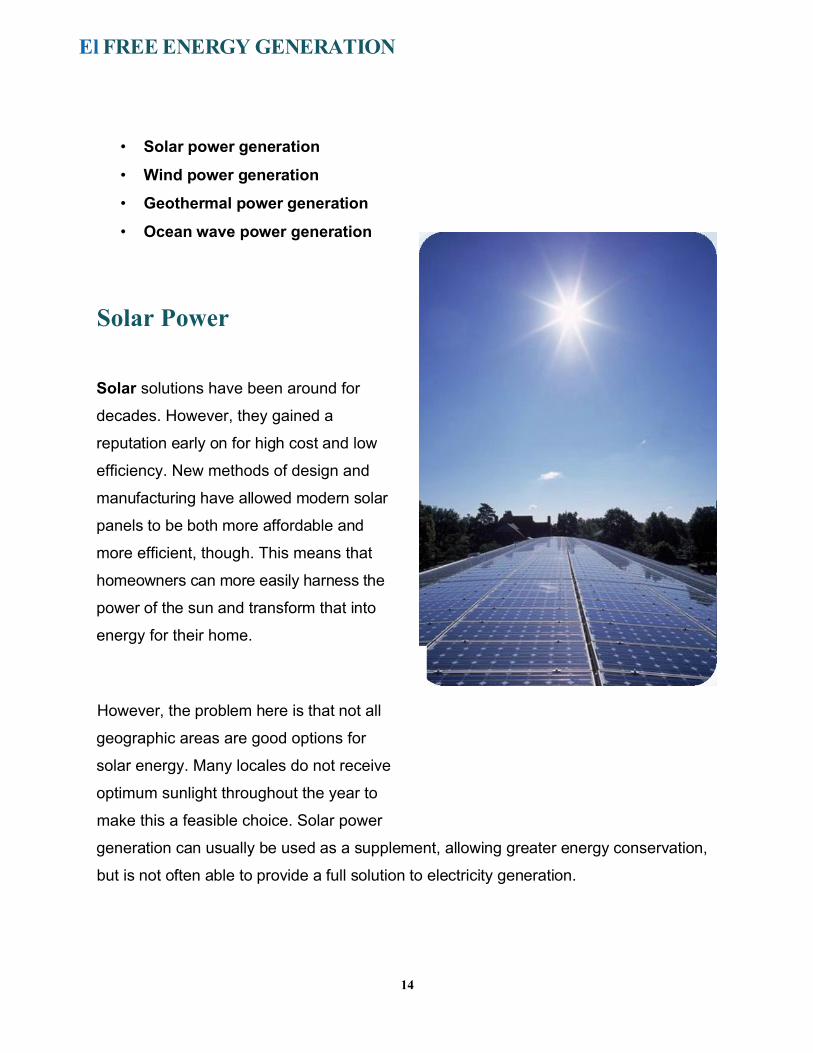
Solar Power
Solar solutions have been around for
decades. However, they gained a
reputation early on for high cost and low
efficiency. New methods of design and
manufacturing have allowed modern solar
panels to be both more affordable and
more efficient, though. This means that
homeowners can more easily harness the
power of the sun and transform that into
energy for their home.
However, the problem here is that not all
geographic areas are good options for
solar energy. Many locales do not receive
optimum sunlight throughout the year to
make this a feasible choice. Solar power
generation can usually be used as a supplement, allowing greater energy conservation,
but is not often able to provide a full solution to electricity generation.
14
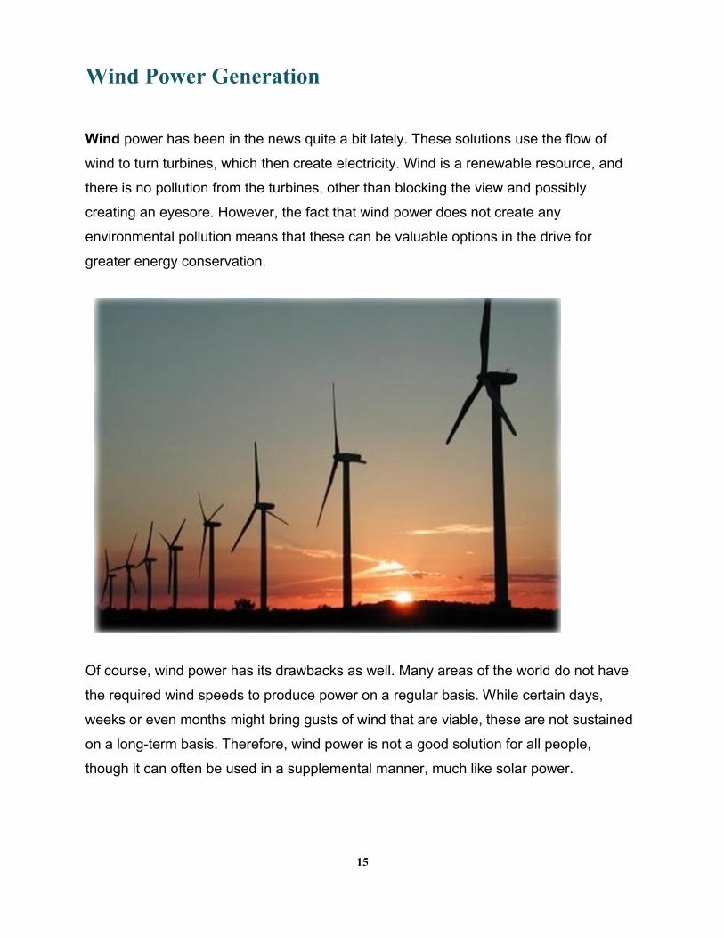
Wind Power Generation
Wind power has been in the news quite a bit lately. These solutions use the flow of
wind to turn turbines, which then create electricity. Wind is a renewable resource, and
there is no pollution from the turbines, other than blocking the view and possibly
creating an eyesore. However, the fact that wind power does not create any
environmental pollution means that these can be valuable options in the drive for
greater energy conservation.
Of course, wind power has its drawbacks as well. Many areas of the world do not have
the required wind speeds to produce power on a regular basis. While certain days,
weeks or even months might bring gusts of wind that are viable, these are not sustained
on a long-term basis. Therefore, wind power is not a good solution for all people,
though it can often be used in a supplemental manner, much like solar power.
15
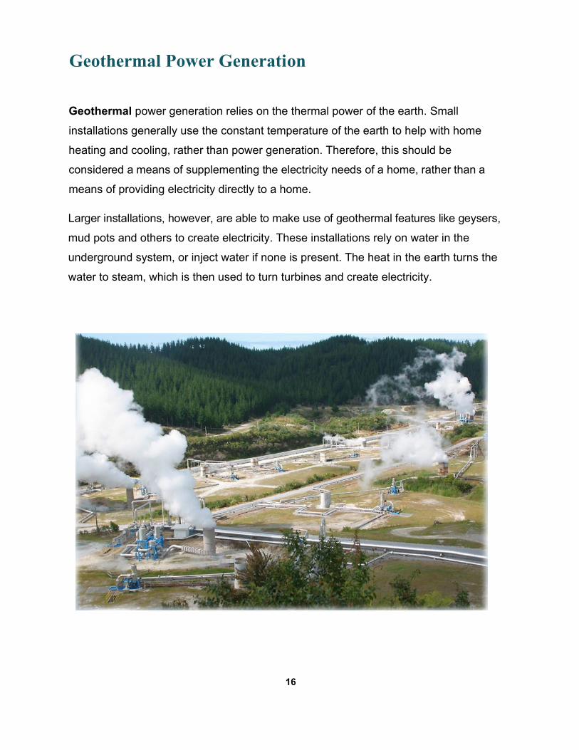
Geothermal Power Generation
Geothermal power generation relies on the thermal power of the earth. Small
installations generally use the constant temperature of the earth to help with home
heating and cooling, rather than power generation. Therefore, this should be
considered a means of supplementing the electricity needs of a home, rather than a
means of providing electricity directly to a home.
Larger installations, however, are able to make use of geothermal features like geysers,
mud pots and others to create electricity. These installations rely on water in the
underground system, or inject water if none is present. The heat in the earth turns the
water to steam, which is then used to turn turbines and create electricity.
16
Of course, most areas of the globe do not have sufficient geothermal activity for large
installations to be viable. Therefore, smaller heating and cooling-related solutions are
the most frequently used form of this technology.
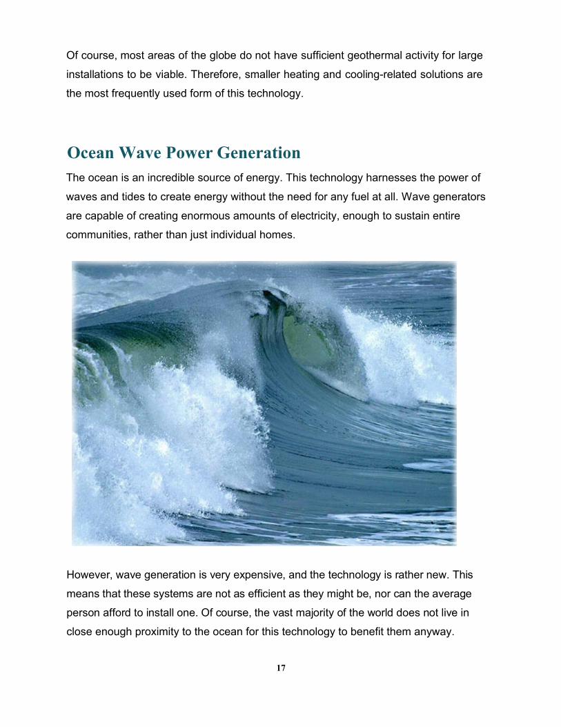
Ocean Wave Power GenerationThe ocean is an incredible source of energy. This technology harnesses the power of
waves and tides to create energy without the need for any fuel at all. Wave generators
are capable of creating enormous amounts of electricity, enough to sustain entire
communities, rather than just individual homes.
However, wave generation is very expensive, and the technology is rather new. This
means that these systems are not as efficient as they might be, nor can the average
person afford to install one. Of course, the vast majority of the world does not live in
close enough proximity to the ocean for this technology to benefit them anyway.
17
Another Alternative
As you can see, the need for energy conservation is incredible. While there are
numerous alternative energy systems that can be used, few of them are able to provide
you with a full solution to your needs. However, there is another alternative available;
one that:
• Can offer free energy for your needs
• Can be built on your own
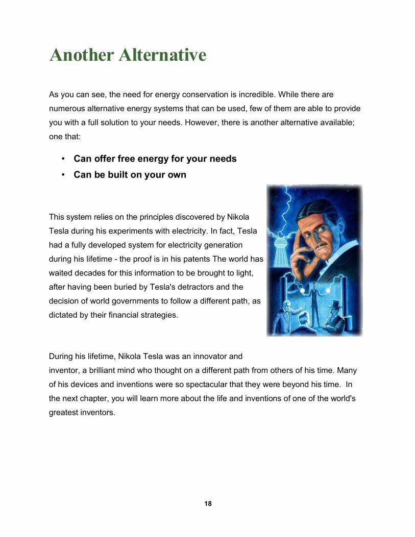
This system relies on the principles discovered by Nikola
Tesla during his experiments with electricity. In fact, Tesla
had a fully developed system for electricity generation
during his lifetime - the proof is in his patents The world has
waited decades for this information to be brought to light,
after having been buried by Tesla's detractors and the
decision of world governments to follow a different path, as
dictated by their financial strategies.
During his lifetime, Nikola Tesla was an innovator and
inventor, a brilliant mind who thought on a different path from others of his time. Many
of his devices and inventions were so spectacular that they were beyond his time. In
the next chapter, you will learn more about the life and inventions of one of the world's
greatest inventors.
18
Chapter 2
A Look into the Person of Nikola Tesla
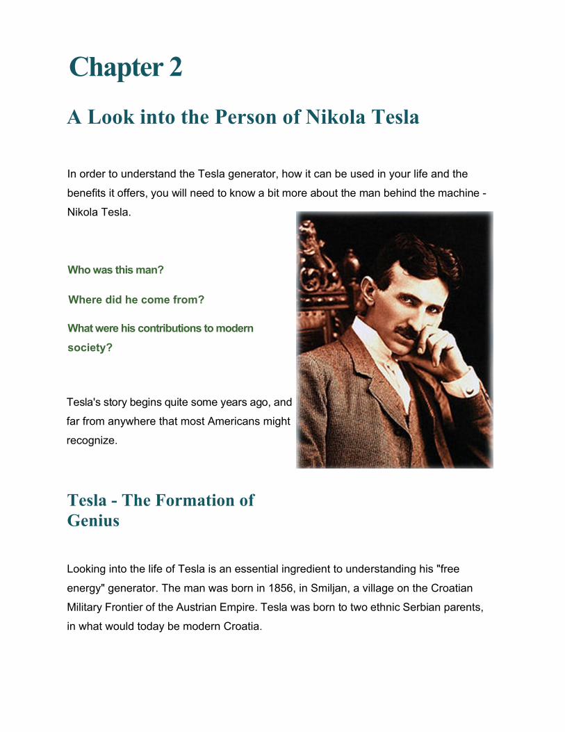
In order to understand the Tesla generator, how it can be used in your life and the
benefits it offers, you will need to know a bit more about the man behind the machine -
Nikola Tesla.
Who was this man?
Where did he come from?
What were his contributions to modern
society?
Tesla's story begins quite some years ago, and
far from anywhere that most Americans might
recognize.
Tesla - The Formation of Genius
Looking into the life of Tesla is an essential ingredient to understanding his "free
energy" generator. The man was born in 1856, in Smiljan, a village on the Croatian
Military Frontier of the Austrian Empire. Tesla was born to two ethnic Serbian parents,
in what would today be modern Croatia.
At birth, Nikola was the fourth youngest of five children. He had one older
brother, Dane, who was killed when Nikola was 5, during an accident while riding
a horse. Nikola had three sisters, named Milka, Angelina and Marica.
During his early years, the family moved to Gospic, where Nikola attended Higher
Real Gymnasium. He completed a full term of study in just three years, going on to
study at the Austrian Polytechnic in Graz.
Tesla, for all his brilliance, did not receive a degree from the university. He actually
stopped attending school after the first semester of his third year. This also marked
the period when he severed all ties with his family, leaving Graz behind.
His whereabouts during this time were unknown, and many of his friends believed that
he had drowned while swimming in a river. In actuality, Tesla had moved to Maribor,
which would become Slovenia at a later date. Here, he worked as an assistant
engineer.
This portion of Tesla's life was relatively short-lived. He suffered a nervous
breakdown during this time, forcing him to quit his job and move once more. Tesla
reconnected with his family, and his father convinced him that studying at Charles-
Ferdinand University in Prague was the best option. Tesla entered the university, but
his father's death soon after forced him to leave again after completing just a single
term.
Sickness and Disability
Throughout his life, Tesla was subjected to various illnesses. He was also prone to
suffer from "visions" and "bright lights," which may have been the ocular hallucinations
that sometimes accompany migraine headaches.
During these episodes, Tesla professed to receive inspiration that supplied him with
the answer to a particular problem with which he had been wrestling, or having a
fully formed vision in his mind of a particular word or item. Modern synesthetes
suffer similarly.
Beginning in early childhood, Tesla was also subjected to flashbacks of previous events
that had happened in his life. This was to go on throughout his life, and figured
prominently in his later life and eccentricity.
Further Changes - Life Abroad
After the death of his father and withdrawal from the university, Tesla moved to
Budapest. Here, he worked for a telegraph company, and later went on to be involved
to a considerable degree with the National Telephone Company, where he became the
engineer for the nation's first telephone system. During this time, he invented a device
that might have been a loudspeaker, or might have been a telephone repeater/amplifier
(sources are unsure).
His stint in Budapest only lasted for two years. In 1882, he moved to France, where he
found a job in Paris. The Continental Edison Company was his source of employment,
where he worked as a designer, improving equipment based on the ideas of Thomas
Edison. He also began working on his rotating magnetic field devices and developed
the induction motor at this time, though it was not until 1888 that he received any type of
patent.
Tesla's mother died shortly after his arrival in Paris (a death he claimed to have
experienced in a dream), and Tesla himself became ill once more and spent several
weeks recovering in Gospic, where his mother had been born.
21
Working with Edison
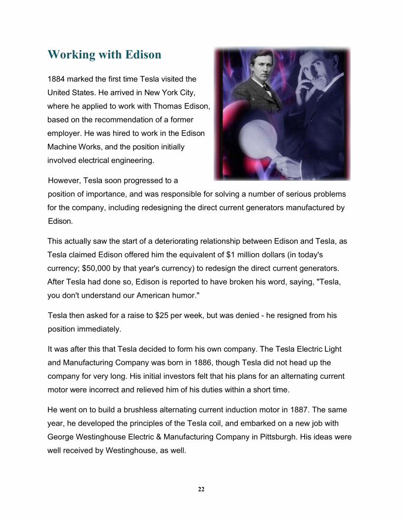
1884 marked the first time Tesla visited the
United States. He arrived in New York City,
where he applied to work with Thomas Edison,
based on the recommendation of a former
employer. He was hired to work in the Edison
Machine Works, and the position initially
involved electrical engineering.
However, Tesla soon progressed to a
position of importance, and was responsible for solving a number of serious problems
for the company, including redesigning the direct current generators manufactured by
Edison.
This actually saw the start of a deteriorating relationship between Edison and Tesla, as
Tesla claimed Edison offered him the equivalent of $1 million dollars (in today's
currency; $50,000 by that year's currency) to redesign the direct current generators.
After Tesla had done so, Edison is reported to have broken his word, saying, "Tesla,
you don't understand our American humor."
Tesla then asked for a raise to $25 per week, but was denied - he resigned from his
position immediately.
It was after this that Tesla decided to form his own company. The Tesla Electric Light
and Manufacturing Company was born in 1886, though Tesla did not head up the
company for very long. His initial investors felt that his plans for an alternating current
motor were incorrect and relieved him of his duties within a short time.
He went on to build a brushless alternating current induction motor in 1887. The same
year, he developed the principles of the Tesla coil, and embarked on a new job with
George Westinghouse Electric & Manufacturing Company in Pittsburgh. His ideas were
well received by Westinghouse, as well.
22
Later that same year, Tesla began experimenting with X-rays, via a device of his own
invention. This system differed considerably from those of other inventors and
researchers, and he even identified the damage caused by X-rays, which was later
attributed to Wilhelm Rontgern.
However, the fact that Tesla did not make his findings widely known contributed to his
not being credited with any important discoveries in the field, at least in period writings.
In 1891, Tesla demonstrated another of his inventions, one that would allow the
transmission of electricity without the need for conductive wires. This came to be called
the Tesla Principle, and has been shown to work very effectively by passing electricity
through space and matter, without the need for cumbersome "power lines."
Tesla Becomes an American Citizen
The War of Currents
Nikola Tesla officially became an American citizen (through naturalization) on July 30,
1891. He was 35 years old at the time. The same year, he started another laboratory,
located on South Fifth Avenue in New York City. Another laboratory on East Houston
Street followed shortly thereafter. Tesla used these two locations to demonstrate how
the Tesla Principle worked, lighting two electric lamps (one in each laboratory) without
any wires involved.
About this same time, Edison and Westinghouse began what came to be known as the
"War of the Currents." Edison was a proponent of DC voltage, while Westinghouse and
Tesla preferred the more efficient AC voltage. However, the battle between
Westinghouse and Edison left both companies on the brink of ruin and prompted Tesla
to release Westinghouse from his contract, eliminating royalty payments for Tesla's
work.
23
After the conclusion of the War of Currents, Tesla actually filed the first radio patent,
and showed a radio-controlled boat to the US military only a year later. A public
demonstration of a radio-controlled boat took place in 1898, though the technology did
little until it reemerged in the 1960s. Tesla also patented a design for what would later
become the standard spark plug used in gasoline engines, as well.
The Move to Colorado Springs
In 1899, Tesla moved his base of operations from New York City to Colorado Springs.
He felt that the area was better suited to his research in electricity, as well as in wireless
telegraphy.
At his new lab, Tesla made some of his most astonishing discoveries and created some
of his most unique inventions. For instance, he proved that the earth was a conductor,
and that it resonated at about 8 Hz. This was confirmed years later, and named the
Schumann Resonance, leaving Tesla's contribution out entirely.
He also experimented more with the Tesla Principle, using wireless light bulbs of his
own design to experiment and refine his technology. Ultimately, while his time in the
area produced numerous devices and new technology, the lab was closed and torn
down.
Tesla's mountain of debt was paid off by selling his equipment. However, this was not
the end for Nikola Tesla. He made the move to a new lab and began construction of the
Wardenclyffe Tower, with money borrowed from J.P. Morgan.
It was also during this time that Tesla demonstrated his bladeless turbine design, with
several of the devices operating at very high RPM (up to 5,000 RPM).
24
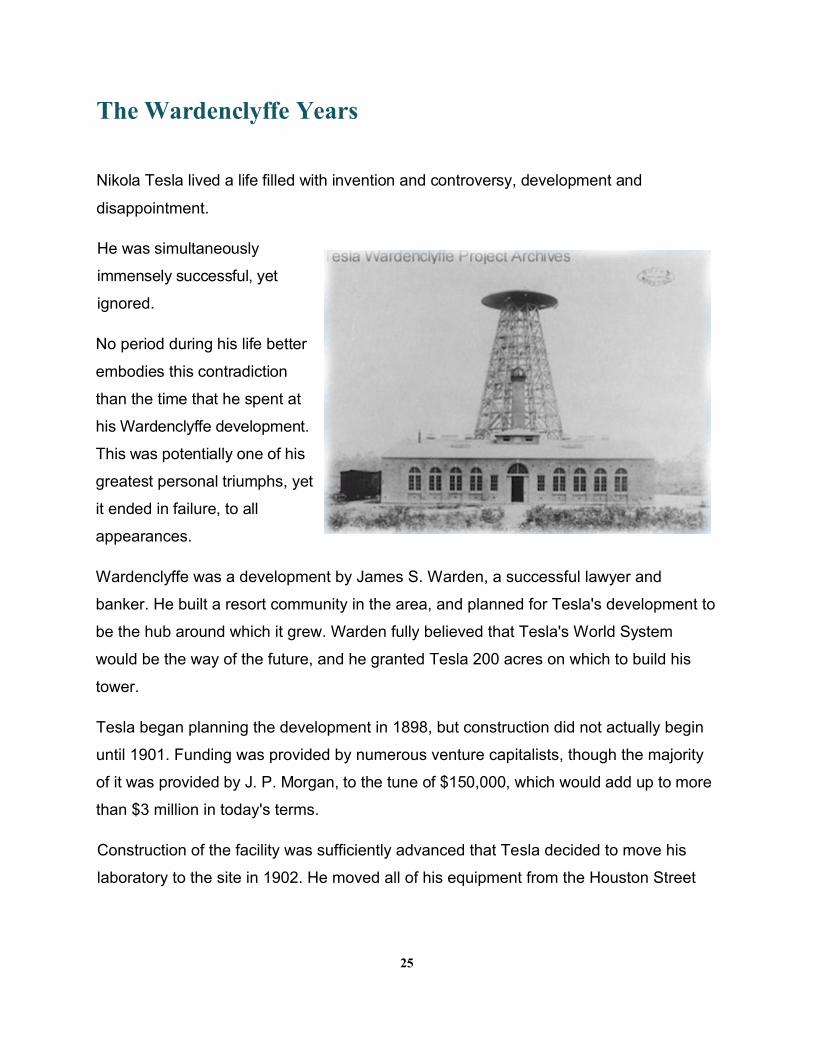
The Wardenclyffe Years
Nikola Tesla lived a life filled with invention and controversy, development and
disappointment.
He was simultaneously
immensely successful, yet
ignored.
No period during his life better
embodies this contradiction
than the time that he spent at
his Wardenclyffe development.
This was potentially one of his
greatest personal triumphs, yet
it ended in failure, to all
appearances.
Wardenclyffe was a development by James S. Warden, a successful lawyer and
banker. He built a resort community in the area, and planned for Tesla's development to
be the hub around which it grew. Warden fully believed that Tesla's World System
would be the way of the future, and he granted Tesla 200 acres on which to build his
tower.
Tesla began planning the development in 1898, but construction did not actually begin
until 1901. Funding was provided by numerous venture capitalists, though the majority
of it was provided by J. P. Morgan, to the tune of $150,000, which would add up to more
than $3 million in today's terms.
Construction of the facility was sufficiently advanced that Tesla decided to move his
laboratory to the site in 1902. He moved all of his equipment from the Houston Street
25
laboratory to the new site at this time, though the tower itself did not near completion
until a year later, in 1903.
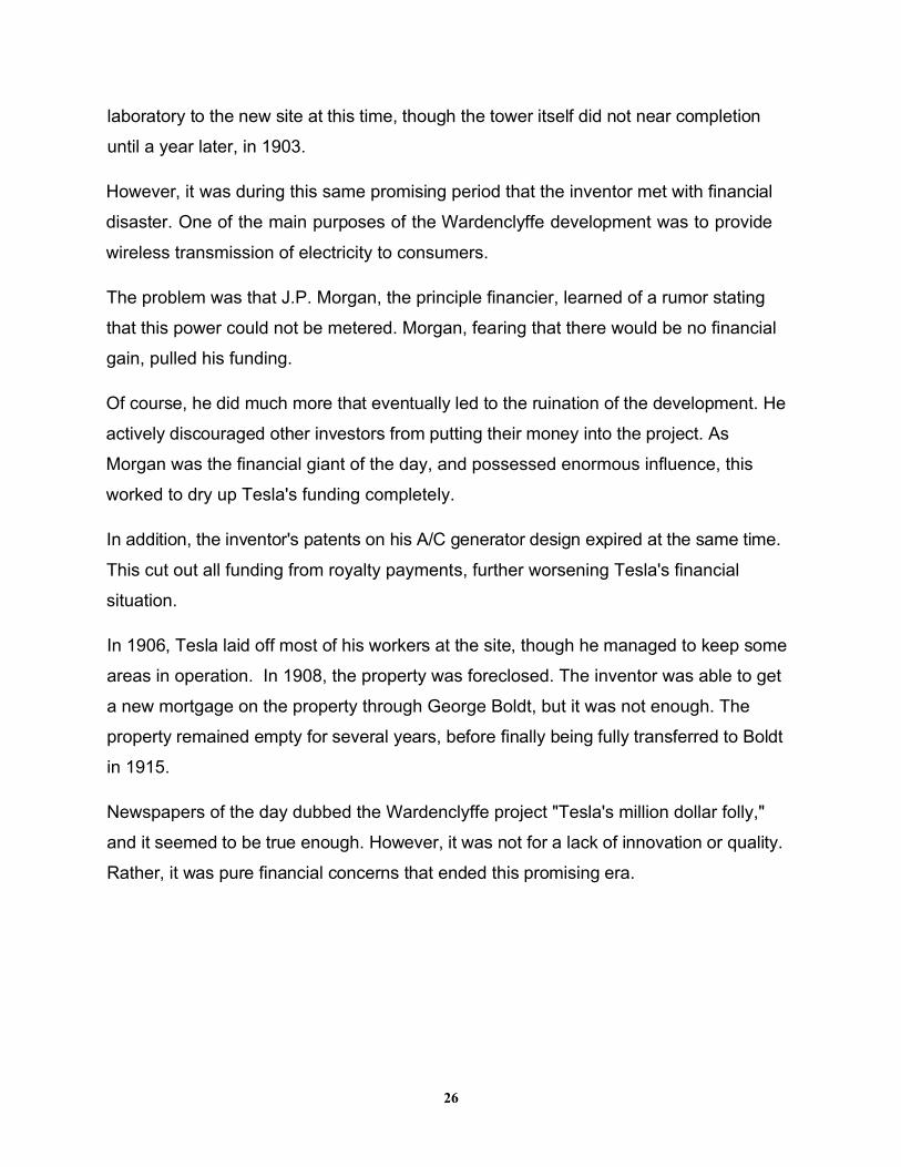
However, it was during this same promising period that the inventor met with financial
disaster. One of the main purposes of the Wardenclyffe development was to provide
wireless transmission of electricity to consumers.
The problem was that J.P. Morgan, the principle financier, learned of a rumor stating
that this power could not be metered. Morgan, fearing that there would be no financial
gain, pulled his funding.
Of course, he did much more that eventually led to the ruination of the development. He
actively discouraged other investors from putting their money into the project. As
Morgan was the financial giant of the day, and possessed enormous influence, this
worked to dry up Tesla's funding completely.
In addition, the inventor's patents on his A/C generator design expired at the same time.
This cut out all funding from royalty payments, further worsening Tesla's financial
situation.
In 1906, Tesla laid off most of his workers at the site, though he managed to keep some
areas in operation. In 1908, the property was foreclosed. The inventor was able to get
a new mortgage on the property through George Boldt, but it was not enough. The
property remained empty for several years, before finally being fully transferred to Boldt
in 1915.
Newspapers of the day dubbed the Wardenclyffe project "Tesla's million dollar folly,"
and it seemed to be true enough. However, it was not for a lack of innovation or quality.
Rather, it was pure financial concerns that ended this promising era.
26
Tesla's Final Years
The final years of Nikola Tesla's life were marked by mounting debt, controversy and
battles for patent control. The US government reversed their initial decision concerning
Tesla's radio patent, giving it to Marconi, instead. This started a lengthy battle between
Tesla and Marconi, which Tesla eventually lost.
This also marked the date when the Wardenclyffe Tower property was seized by US
marines and demolished (1917), because it was feared the facility could be used by
spies of the German government.
During these years, Tesla began experimenting with radar, and actually established the
first principles for its operation. However, he is most notorious for the "ray gun" systems
that he attempted to sell to world governments during this time. No government entered
a bid for such a weapon, so it was never constructed (and its operation thus never
assessed).
It was during these later years that the inventor began suffering from what appeared to
be obsessive-compulsive disorder. However, at the time, there was no scientific
diagnosis, and the condition was simply believed to be a manifestation of insanity. This
was bolstered by Tesla's arguments concerning the work of Albert Einstein, calling it
"filled with underlying errors."
Tesla died in 1943, of heart failure. He was indebted to a considerable degree, but the
US Supreme Court did uphold one of his patents, which became the basis for patented
radio technology, at least within the United States. During his life, Nikola Tesla was
awarded 111 different patents, and one patent was reissued (Method of Insulating
Electric Conductors). He also had patents in Great Britain, in Canada and in Spain.
However, while the man contributed immense amounts to science and technology, it is
his theoretical and implied inventions that garner the most interest in the modern day.
These were all theorized, planned or claimed to have been built by Tesla.
27
Thought Camera
Antigravity Aircraft
Free Energy Earthquake
Machine Teleforce
Electric Submarine
Death Ray
Mechanical Oscillator
Force Field
Of course, the free energy device is one of the most important on this list. This device
worked based on renewable electricity and heat gathered from the surrounding natural
world, rather than creating energy from nothing at all. Many are more familiar with this
concept as Tesla's Fuel-less Generator, which incorporated two of his more famous
inventions - his bladeless turbine and his radiant energy device.
28
Chapter 3
Tesla's Inspiration for Radiant Energy
Generation
In order to understand Tesla's inventions and how the system actually works, it is
important to know how he derived his inspiration.
How did Nikola Tesla arrive at the idea of a radiant energy system?
What spurred his imagination? What factors influenced his thinking?
In this chapter, you will learn more about the "how" and "why" of Tesla's invention.
Tesla's Introduction to Radiant Energy
Interestingly, it was while Tesla was employed by Thomas Edison that he had his first
brush with what he would come to call radiant energy. At the time, it was simply
referred to as "the blue spike phenomenon."
At this time, Edison's DC generators were the only devices capable of providing
electricity to homes and businesses. However, the fact that these generators produced
direct current was a problem, though Edison refused to admit this.
29
Long transmission lines leading to the generators built up an enormous amount of
electrical resistance. In order to overcome this, Edison had to build very powerful
generators, capable of producing very high voltage. This electricity was then
transmitted through the power lines and into the homes and businesses of Edison's
customers.
The blue spike phenomenon was noticed when the generators were first switched on.
When the switch was thrown to send the electricity from the generator through the
power lines, blue electrical spikes were noticed along the power line. This lasted only
for an instant - once the resistance of the line was overcome, the spikes disappeared.
If a particularly strong voltage was released from the generator, the phenomenon was
much stronger. A strong "stinging" sensation was noticed in the people nearby. In
these instances, Tesla occasionally observed the spike jumping from the power line and
grounding itself into the earth. If a worker happened to be in the way, the arc would
ground through him, killing him immediately.
What Did the Blue Spike Phenomenon Mean?
Tesla was unsure of what caused the blue spike phenomenon, though it greatly piqued
his curiosity. He did know that the conclusion others had reached, that electrons
caused the phenomenon, was incorrect. In fact, he had a strong suspicion that the
phenomenon was related to his current studies on energy.
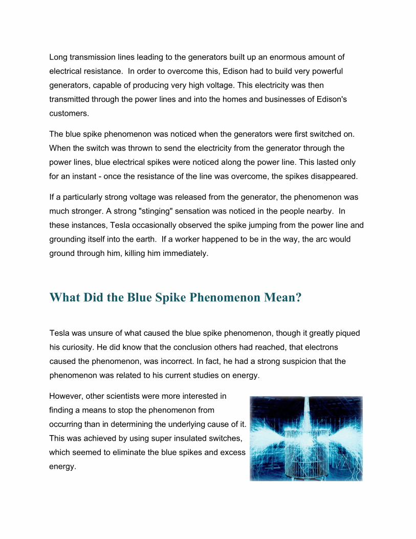
However, other scientists were more interested in
finding a means to stop the phenomenon from
occurring than in determining the underlying cause of it.
This was achieved by using super insulated switches,
which seemed to eliminate the blue spikes and excess
energy.
Tesla Begins Experimentation
His curiosity aroused by the blue spike phenomenon, Tesla began experimenting to
determine the source. He started by using highly charged capacitors that were
discharged in extremely short intervals. These pulses seemed to duplicate the
"stinging" sensation noticed with Edison's generators.
Tesla immediately saw the connection between his own experiments and the discharge
phenomenon in DC generators, and was able to calculate that the electrical discharge
responsible for the stinging sensation and the blue spikes was hundreds of times
stronger than the voltage flowing through the power lines. For Tesla, the question was:
Where did the energy come from? What caused it?
Through his ongoing research, he was able to replicate the high voltage Shockwaves at
any time. He noted that the sensation happened no matter where he might be in the
laboratory - the waves were able to penetrate any substance that might be between
him and the capacitor. He decided that he would call this new form radiant energy, as it
clearly was not an electromagnetic wave.
The Conclusion of Tesla's Experiments
In addition to conducting his own experiments, Nikola Tesla also searched for
corresponding evidence in the experiments of other scientists and innovators. He found
a few instances where the results of various experiments mirrored his thinking, but no
other person had thought to continue investigating.
31
In conclusion, he determined that there was a presence of some conductive medium,
other than air. He surmised that this medium filled all the space around the earth,
pervading everything. In addition, whatever composed this medium had to be smaller
than an atom, as it was capable of carrying electricity through solid objects.
Further Experimentation with Radiant Energy
In an attempt to further his understanding of radiant energy, Tesla continued
experimenting in various ways. One way in which he did this was the development of a
charging dynamo to provide power and a magnetic discharger. However, this resulted
in yet another discovery.
If he placed the magnetic discharger on one side of the dynamo, then the charge was
positive. However, if he placed it on the other side of the dynamo, the charge was
negative. This showed that the new energy form traveled like a light ray, rather than like
an electromagnetic wave.
He also found that a chain of electrical pulses with less than 100 microseconds between
bursts caused pain in people, and would also cause mechanical pressure. However, if
the duration were reduced to less than 100 microseconds, the pain was eliminated and
the force did not exert mechanical pressure. In addition, if the pulse duration was 1
microsecond, heat was produced, and even shorter duration pulses could create white
light that would illuminate a room.
However, it was the discovery that a single-turn copper helix coil placed nearby the
device would begin emitting sparks that climbed the coil and discharged from the top
that most excited the inventor. This was the earliest form of what would eventually
become his Tesla coil.
During the course of this experiment, Tesla found that the voltage contained within the
coil was far greater than what was being applied to it. This was also interesting
because, unlike other structures, the charge did not pass through the coil. Instead, it
32
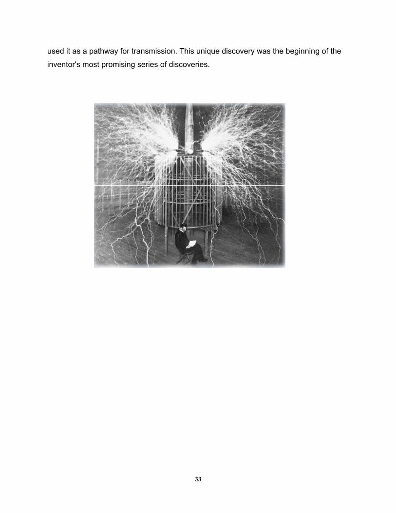
used it as a pathway for transmission. This unique discovery was the beginning of the
inventor's most promising series of discoveries.
33
Chapter 4
Tesla's Radiant Energy Device
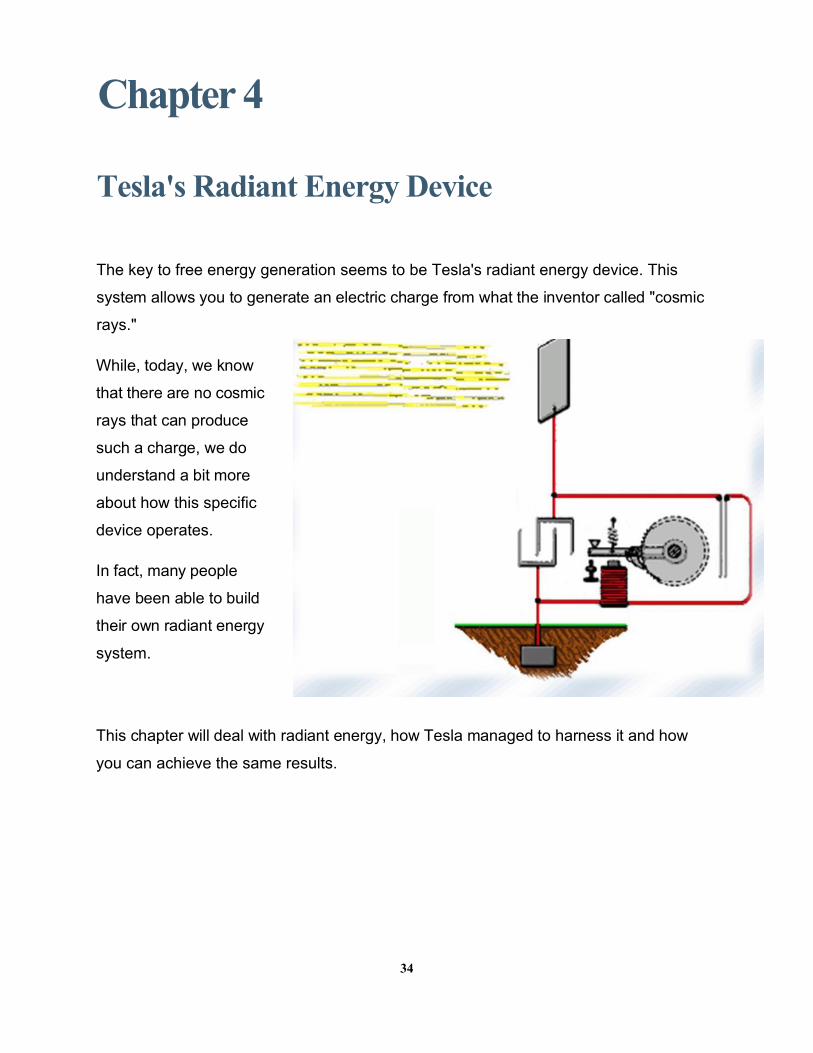
The key to free energy generation seems to be Tesla's radiant energy device. This
system allows you to generate an electric charge from what the inventor called "cosmic
rays."
While, today, we know
that there are no cosmic
rays that can produce
such a charge, we do
understand a bit more
about how this specific
device operates.
In fact, many people
have been able to build
their own radiant energy
system.
This chapter will deal with radiant energy, how Tesla managed to harness it and how
you can achieve the same results.
34
Defining the Term "Radiant Energy"
Much of the confusion surrounding Tesla's proposed system of energy generation
stems from a misunderstanding of radiant energy. While Tesla called this type of
energy "cosmic rays," this term is a bit inaccurate, especially in the light of modern
scientific discoveries. However, this simple fact does not devalue Tesla's discovery.
Rather, it underscores its value and veracity.
In modern parlance, radiant energy refers to the energy of electromagnetic waves.
However, this can be a bit misleading, as well. This definition means the frequency of
those waves, rather than the waves themselves. Tesla spoke of a definable,
measurable source of energy, which would be the actual
electromagnetic waves, rather than their frequency.
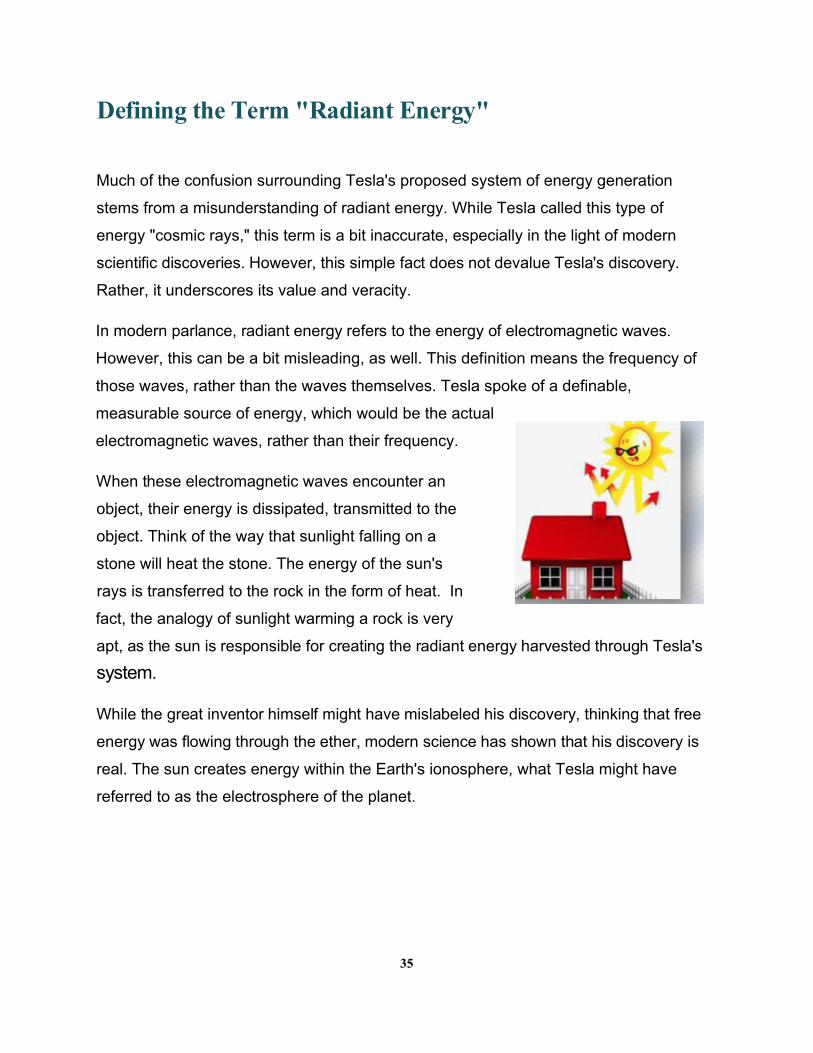
When these electromagnetic waves encounter an
object, their energy is dissipated, transmitted to the
object. Think of the way that sunlight falling on a
stone will heat the stone. The energy of the sun's
rays is transferred to the rock in the form of heat. In
fact, the analogy of sunlight warming a rock is very
apt, as the sun is responsible for creating the radiant energy harvested through Tesla's
system.
While the great inventor himself might have mislabeled his discovery, thinking that free
energy was flowing through the ether, modern science has shown that his discovery is
real. The sun creates energy within the Earth's ionosphere, what Tesla might have
referred to as the electrosphere of the planet.
35
How Is Radiant Energy Created?
Picture the planet earth from space. A black field of space is dotted by stars. Against
this backdrop, the blue marble of planet Earth rests. The sun, 93 million miles distant,
sends light and warmth to the planet. Now, take a closer look at that image of our
planet. How often is the entire planet dark?
The answer, of course, is never. The sun always illuminates half of the planet.
Therefore, the sun is constantly producing energy within Earth's ionosphere.
Because of this constant interaction, there is always an electric charge in the
atmosphere. This energy can be harnessed with a simple method, and applied to a
variety of different uses, just as Tesla suggested in his research notes.
As the sun irradiates Earth's ionosphere, the atmosphere collects a "net positive"
charge. The earth itself, however, has a net negative charge. Therefore, with a radiant
energy system to "harvest" this energy, you could direct kilowatts of energy from the
ionosphere to power another device.
The Argument for and Against "Free" Energy
The world of science is full of controversy and disagreement, regardless of what is
taught in schools. Even the area of alternative energy and energy preservation can be
pocked with pitfalls.
36
One of these is the disagreement about the actuality of "free" energy. There are two
schools of thought on this topic - one that says there is no such thing as "free" energy,
and one that contends it does, indeed, exist.
The Argument Against
The argument against "free" energy is a bit surprising. This crowd does not contend that
the energy does not exist. They take umbrage at the use of the word "free" being
applied to it. The thought here is that this energy exists, has always existed and flows
continuously throughout the entire world, powered by the furnace of the sun.
Therefore, it is not "free" if it is already present. Harnessing this energy is merely
redirecting something that is already present, and there is no act of creation to it. For
instance, energy with a cost might be exemplified best by the changing of mechanical
energy into electrical energy through a traditional hydroelectric power plant.
The Argument For
Proponents of "free" energy cite the fact that the input power needed to create energy
through this method is so low that it is negligible. Therefore, it produces more energy
than what is required in input energy. In this equation, that equals "free," as in no or low
cost to produce electricity.
While this may seem mere semantics, it is an important point, particularly if you will be
studying other sources on the topic available to you. User forums, in particular, are rife
with this sort of argument.
37
How Do You Harness Radiant Energy?
As you might surmise, in order to harness this free energy, you have to be able to
interact with the ionosphere. To do this, you will certainly need an antenna. However,
not just any antenna will suffice. You will need a specialized antenna to help you
redirect the energy within the Earth's atmosphere.
In addition, if you live in a city or within a subdivision with a covenant governing what
you can put outside your house or in your yard, you will need to check into the
regulations that cover you. Below, you will find a brief outline of how to construct an
antenna that will work for your needs.
Building the Antenna
Part of the process of building a working antenna is finding the right materials to
construct the upper portion - the actual part that will collect the charge and direct it
downward to the rest of the system. There are numerous materials that you might use
here, but copper works the best.
Copper wire has a very long history in the world of electricity, due mostly to its high
conductivity, but also to its relative low cost when compared to other good conductors.
Gold and silver are also both excellent conductors, but are far, far too expensive for
such a task. Aluminum is also a good conductor, though it has only about 60% of
copper's conductivity. However, what it lacks in conductivity, it makes up for in
lightness. This allows you to create larger antenna arrays. However, for a basic
antenna, copper is simply the best possible choice economically, and in terms of
conductivity for the price.
38
Here are the materials needed for building the antenna. They can be found in most DIY
centers, electrical supply stores and more. You might even be able to get them from
salvage, which will save you some money.
• 50 feet of copper tubing with 3/4 of an inch in diameter
• 30 feet of fiberglass pipe
• 4 lengths of steel wires
• 1 steel plate about 4 feet square
• 2 lengths of 4-gauge insulated copper wire
• 600 Volt insulated fused single (or 3-phase) disconnect switch
• 4 x 500mfd capacitors
• 1 x 10 K Ohm 10-turn variable resistor
• 1 transformer
The top side of the antenna: once you have your tubing, you need to wind it in a right-
hand spiral. Do not close the gaps between the windings, though - you want to leave
about an inch of empty space between each spiral of the antenna. There are several
ways of winding the copper tube: square, oval and circle. The square one is the most
efficient, but the most difficult to shape. However, the others might be just as well.
When you are finished winding your antenna, you need to mount it on the pole.
For that, use the 30 feet fiberglass pipe which places the top antenna above the
ground, and it should be clear of any nearby obstructions. Remember that the higher
your antenna pole is, the greater the diameter needs to be to support the antenna. In
addition, the height of the antenna is directly proportional to the voltage we want to
obtain. You might decide to install 4 guy-wires to ensure that the pole does not fall over
in wind or adverse weather conditions.
Of course, the antenna is only part of the equation. You need a way to connect that
wound copper tubing to the system at the bottom. Again, there are numerous options
that you might choose to utilize here.
39
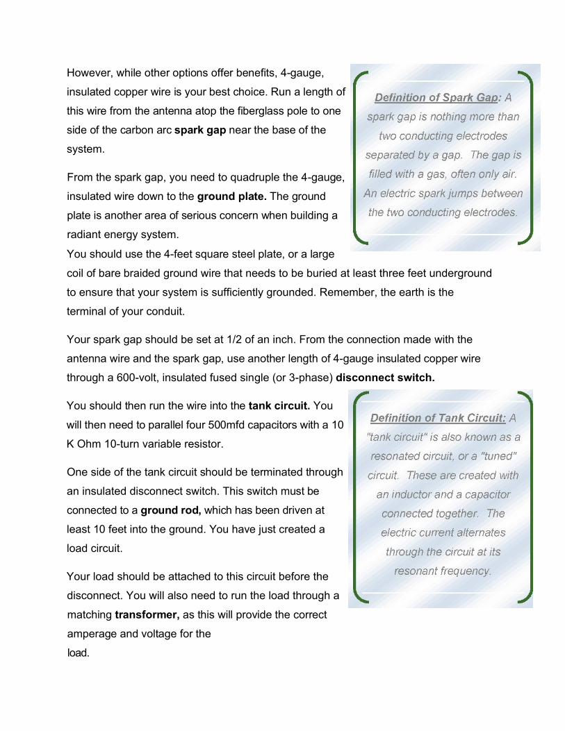
However, while other options offer benefits, 4-gauge,
insulated copper wire is your best choice. Run a length of
this wire from the antenna atop the fiberglass pole to one
side of the carbon arc spark gap near the base of the
system.
From the spark gap, you need to quadruple the 4-gauge,
insulated wire down to the ground plate. The ground
plate is another area of serious concern when building a
radiant energy system.
You should use the 4-feet square steel plate, or a large
coil of bare braided ground wire that needs to be buried at least three feet underground
to ensure that your system is sufficiently grounded. Remember, the earth is the
terminal of your conduit.
Your spark gap should be set at 1/2 of an inch. From the connection made with the
antenna wire and the spark gap, use another length of 4-gauge insulated copper wire
through a 600-volt, insulated fused single (or 3-phase) disconnect switch.
You should then run the wire into the tank circuit. You
will then need to parallel four 500mfd capacitors with a 10
K Ohm 10-turn variable resistor.
One side of the tank circuit should be terminated through
an insulated disconnect switch. This switch must be
connected to a ground rod, which has been driven at
least 10 feet into the ground. You have just created a
load circuit.
Your load should be attached to this circuit before the
disconnect. You will also need to run the load through a
matching transformer, as this will provide the correct
amperage and voltage for the
load.
Safety Precautions
When operating a system such as this, it is important that you always open the
disconnect to the ground circuit when you need to shut off the power. You should then
open the disconnect before the tank circuit, in order to isolate the voltage control.
When the system is off, you will notice that the spark gap occasionally arcs, but this is
nothing to fear. It is simply charge buildup in the system.
As a note, the closer you can tune the frequencies of the tank circuit and the antenna,
the better. The closer the frequencies, the higher the attainable energy you are able to
transfer from the antenna to the ground, supplying you with more electricity to power
your load.
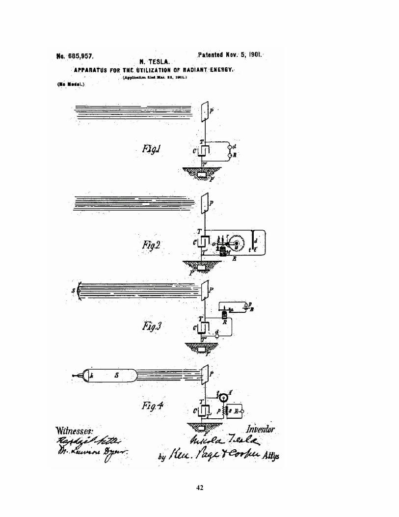
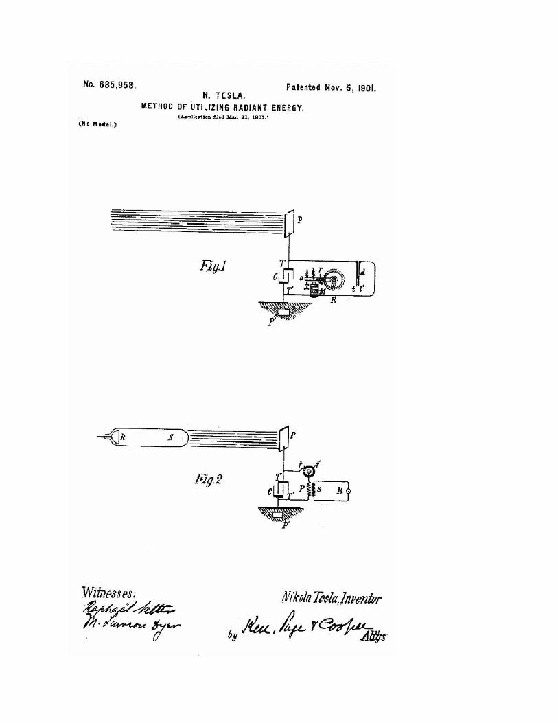
Designs
Here are some of Nikola Tesla's original designs for a radiant energy system. These
were his actual illustrations for two of his patents filed with the US government.
41
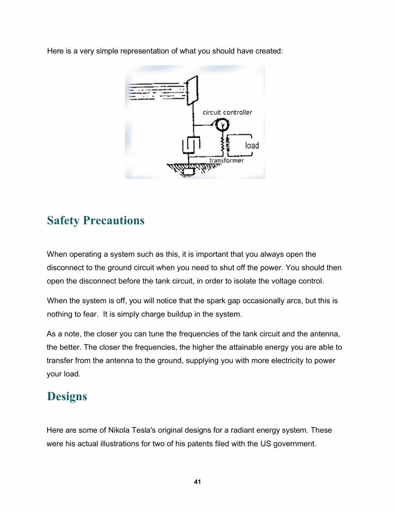
Here is a very simple representation of what you should have created:
42
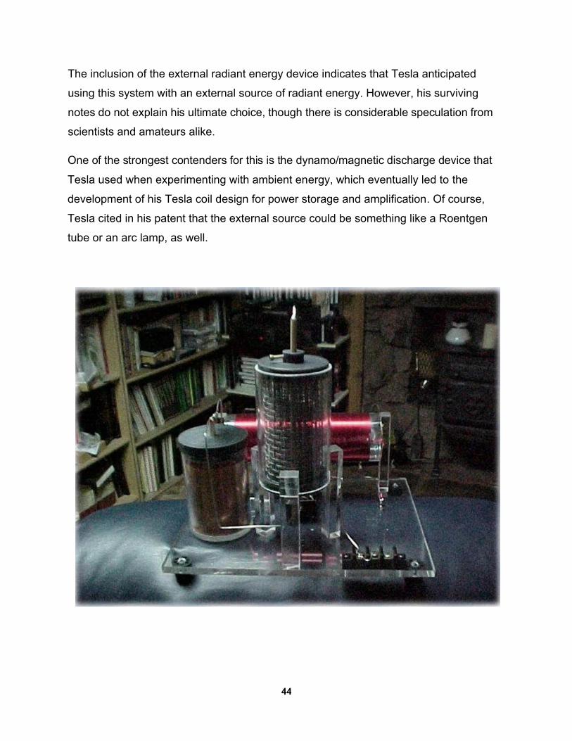
The inclusion of the external radiant energy device indicates that Tesla anticipated
using this system with an external source of radiant energy. However, his surviving
notes do not explain his ultimate choice, though there is considerable speculation from
scientists and amateurs alike.
One of the strongest contenders for this is the dynamo/magnetic discharge device that
Tesla used when experimenting with ambient energy, which eventually led to the
development of his Tesla coil design for power storage and amplification. Of course,
Tesla cited in his patent that the external source could be something like a Roentgen
tube or an arc lamp, as well.
44
Chapter 5
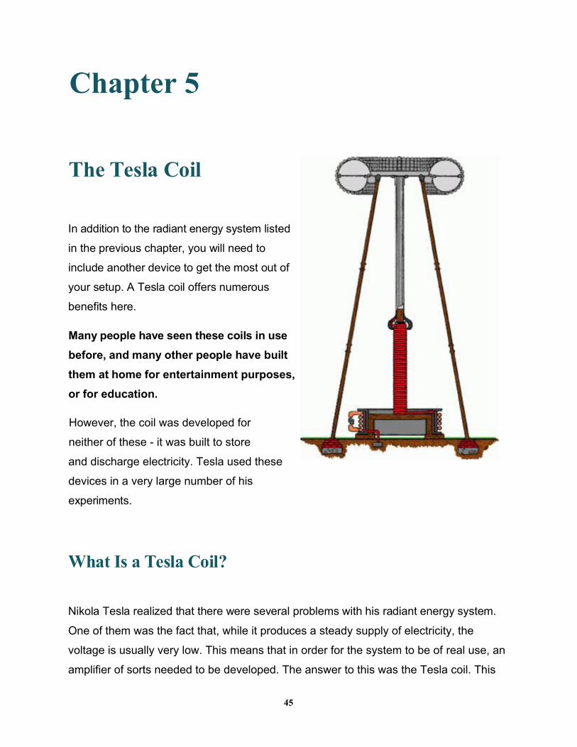
The Tesla Coil
In addition to the radiant energy system listed
in the previous chapter, you will need to
include another device to get the most out of
your setup. A Tesla coil offers numerous
benefits here.
Many people have seen these coils in use
before, and many other people have built
them at home for entertainment purposes,
or for education.
However, the coil was developed for
neither of these - it was built to store
and discharge electricity. Tesla used these
devices in a very large number of his
experiments.
What Is a Tesla Coil?
Nikola Tesla realized that there were several problems with his radiant energy system.
One of them was the fact that, while it produces a steady supply of electricity, the
voltage is usually very low. This means that in order for the system to be of real use, an
amplifier of sorts needed to be developed. The answer to this was the Tesla coil. This
45
device is similar to other types of resonant transformers, but it has some significant
differences.
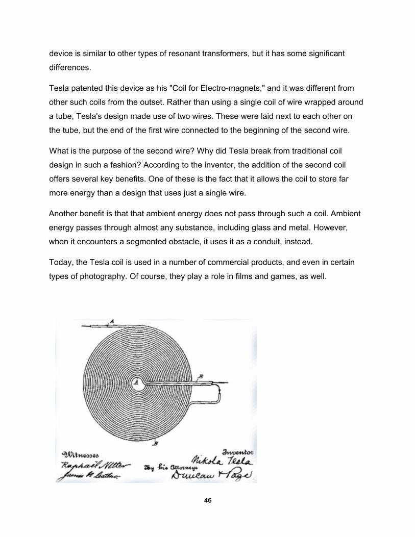
Tesla patented this device as his "Coil for Electro-magnets," and it was different from
other such coils from the outset. Rather than using a single coil of wire wrapped around
a tube, Tesla's design made use of two wires. These were laid next to each other on
the tube, but the end of the first wire connected to the beginning of the second wire.
What is the purpose of the second wire? Why did Tesla break from traditional coil
design in such a fashion? According to the inventor, the addition of the second coil
offers several key benefits. One of these is the fact that it allows the coil to store far
more energy than a design that uses just a single wire.
Another benefit is that that ambient energy does not pass through such a coil. Ambient
energy passes through almost any substance, including glass and metal. However,
when it encounters a segmented obstacle, it uses it as a conduit, instead.
Today, the Tesla coil is used in a number of commercial products, and even in certain
types of photography. Of course, they play a role in films and games, as well.
46
How Does the Coil Work In A Self-Sustaining Energy
System?
In order to understand just how such a solution might work, we need to go back to
Tesla's theory of how radiant energy was available throughout the world, at all times of
the day or night. This is summed up quite well by the inventor's own statement:
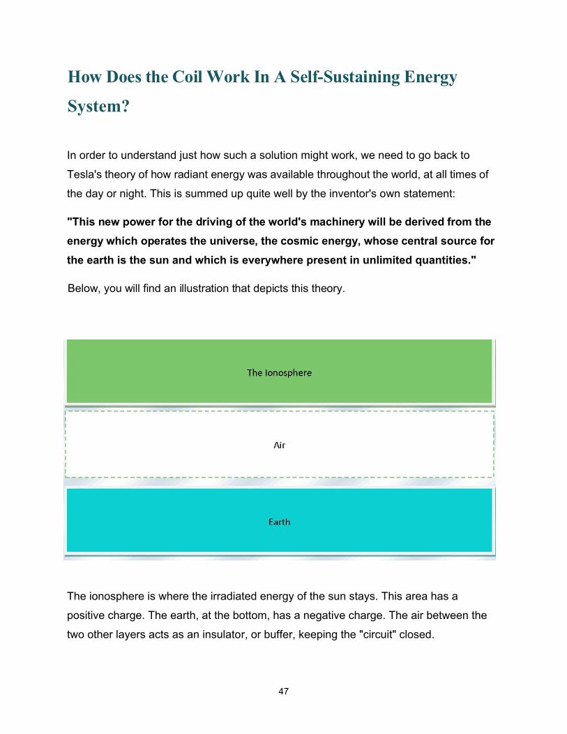
"This new power for the driving of the world's machinery will be derived from the
energy which operates the universe, the cosmic energy, whose central source for
the earth is the sun and which is everywhere present in unlimited quantities."
Below, you will find an illustration that depicts this theory.
The ionosphere is where the irradiated energy of the sun stays. This area has a
positive charge. The earth, at the bottom, has a negative charge. The air between the
two other layers acts as an insulator, or buffer, keeping the "circuit" closed.
47
However, with a radiant energy system, you are able to connect to the energy
circulating around the earth and redirect it. Through circuit loads, you are able to make
this energy perform work for you, on its way to the ground.
Think of this energy the same way you would the energy created by Tesla's dynamo in
his experiments mentioned previously. It is a definite charge, but not necessarily strong
enough for all tasks. However, just like in his experiments, you can put a Tesla coil into
the equation.
The way this works is that the coil is set in operation by an external force. This is
always the case with Tesla coils, but in the application being discussed here, the
external force is the energy generated by the antenna and copper lines mentioned
previously.
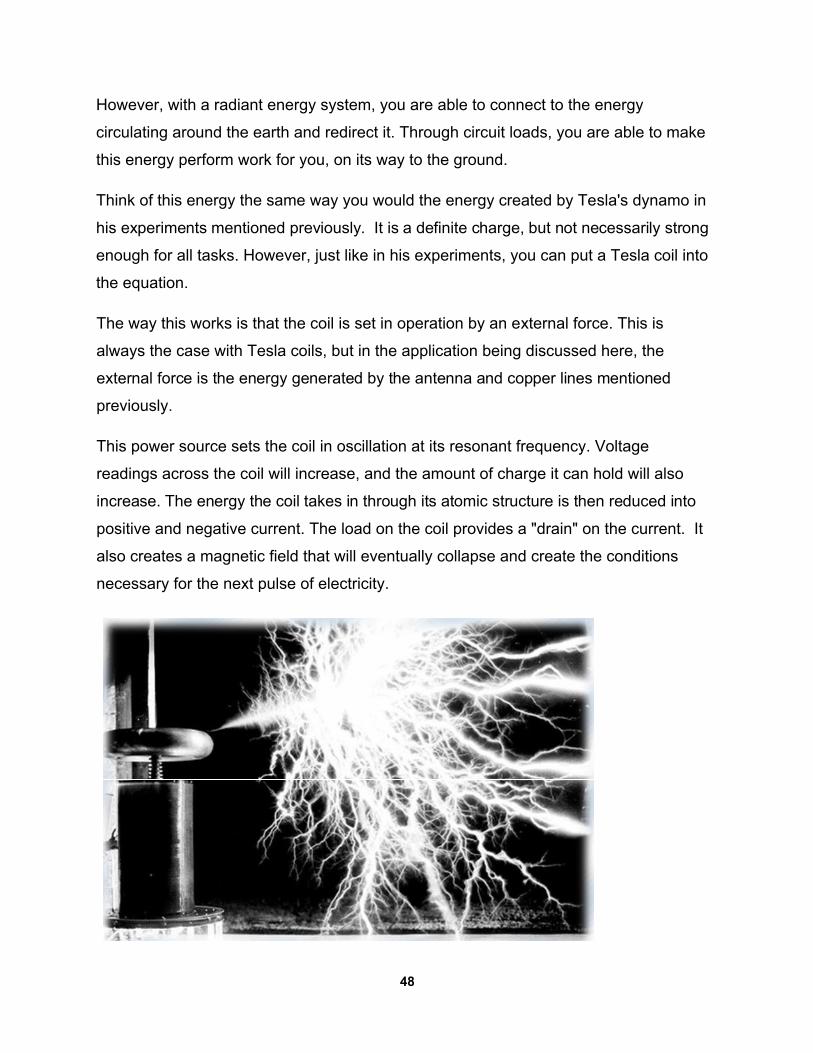
This power source sets the coil in oscillation at its resonant frequency. Voltage
readings across the coil will increase, and the amount of charge it can hold will also
increase. The energy the coil takes in through its atomic structure is then reduced into
positive and negative current. The load on the coil provides a "drain" on the current. It
also creates a magnetic field that will eventually collapse and create the conditions
necessary for the next pulse of electricity.
48
How to build a real Tesla Coil that can generate lightning
A Lightning Generator Capable of generating small miniature lightning bolts up to 24-in.
long the device is unusually potent considering its overall simplicity and minimal power
requirements.
In operation, the Lightning Generator spouts a continuous, crackling discharge of
pulsating lightning bolts into the air. These waving fingers of electricity will strike any
conducting object that comes within its range.
A piece of paper placed on top the discharge terminal will burst into flames after a few
seconds of operation and a balloon tossed near the terminal will pop as though shot
down by lightning.
WARNING: High voltage is dangerous! Use rubber gloves.If you are not familiar with high voltage rules then do not attempt this project until you educate yourself in the use of HV Capacitors and high voltage safety. See your local library or get a beginnersbook on electronics.
Building the Lightning Generator is relatively simple.
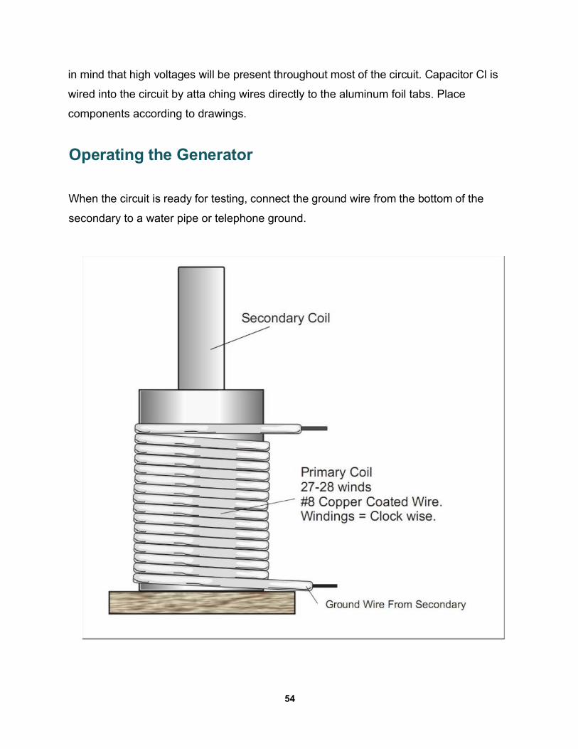
- Start with L2, the secondary coil, which consists of a 36 1/2-in. length of 17/8-in.
OD cardboard tubing, wound with a single layer of AWG 30 enameled, copper
wire. Choose as perfect a tube as possible and make sure that it is not
contaminated with paint or other substances.
- Heat the tube in an oven to drive out moisture and paint it lightly with varnish or
plastic spray. The coil can be wound by hand or chucked in a slow-turning lathe.
- Starting 1/4-in. from the end, begin winding clockwise, making all turns as tight
and as close together as possible. Avoid kinks and overlapping. Total number of
49
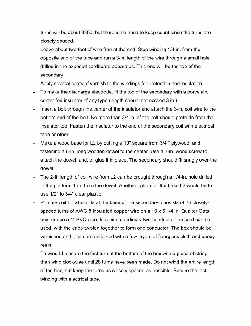
turns will be about 3350, but there is no need to keep count since the turns are
closely spaced.
- Leave about two feet of wire free at the end. Stop winding 1/4 in. from the
opposite end of the tube and run a 3-in. length of the wire through a small hole
drilled in the exposed cardboard apparatus. This end will be the top of the
secondary.
- Apply several coats of varnish to the windings for protection and insulation.
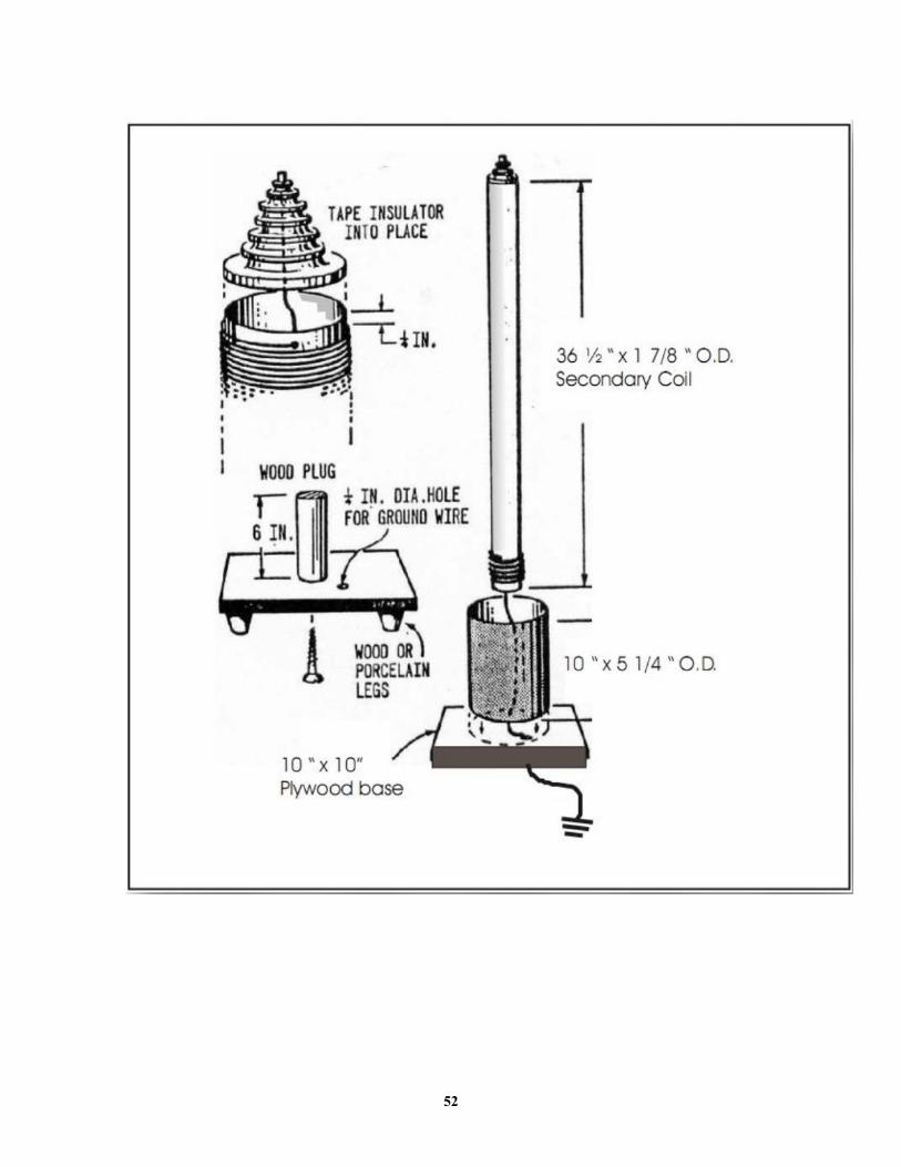
- To make the discharge electrode, fit the top of the secondary with a porcelain,
center-fed insulator of any type (length should not exceed 3 in.).
- Insert a bolt through the center of the insulator and attach the 3-in. coil wire to the
bottom end of the bolt. No more than 3/4 in. of the bolt should protrude from the
insulator top. Fasten the insulator to the end of the secondary coil with electrical
tape or other.
- Make a wood base for L2 by cutting a 10" square from 3/4 " plywood, and
fastening a 6-in. long wooden dowel to the center. Use a 3-in. wood screw to
attach the dowel, and, or glue it in place. The secondary should fit snugly over the
dowel.
- The 2-ft. length of coil wire from L2 can be brought through a 1/4-in. hole drilled
in the platform 1 in. from the dowel. Another option for the base L2 would be to
use 1/2" to 3/4" clear plastic.
- Primary coil LI. which fits at the base of the secondary, consists of 28 closely-
spaced turns of AWG 8 insulated copper wire on a 10 x 5 1/4 in. Quaker Oats
box. or use a 4" PVC pipe. In a pinch, ordinary two-conductor line cord can be
used, with the ends twisted together to form one conductor. The box should be
varnished and it can be reinforced with a few layers of fiberglass cloth and epoxy
resin.
- To wind LI, secure the first turn at the bottom of the box with a piece of string,
then wind clockwise until 28 turns have been made. Do not wind the entire length
of the box, but keep the turns as closely spaced as possible. Secure the last
winding with electrical tape.
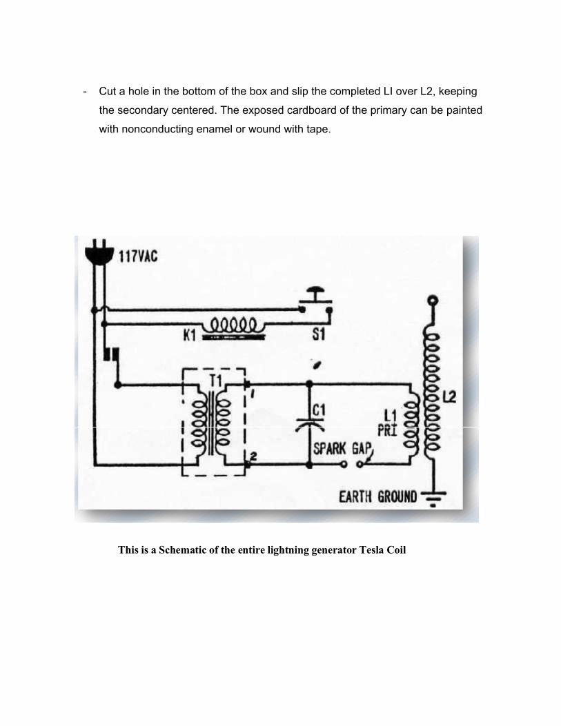
- Cut a hole in the bottom of the box and slip the completed LI over L2, keeping
the secondary centered. The exposed cardboard of the primary can be painted
with nonconducting enamel or wound with tape.
This is a Schematic of the entire lightning generator Tesla Coil
52
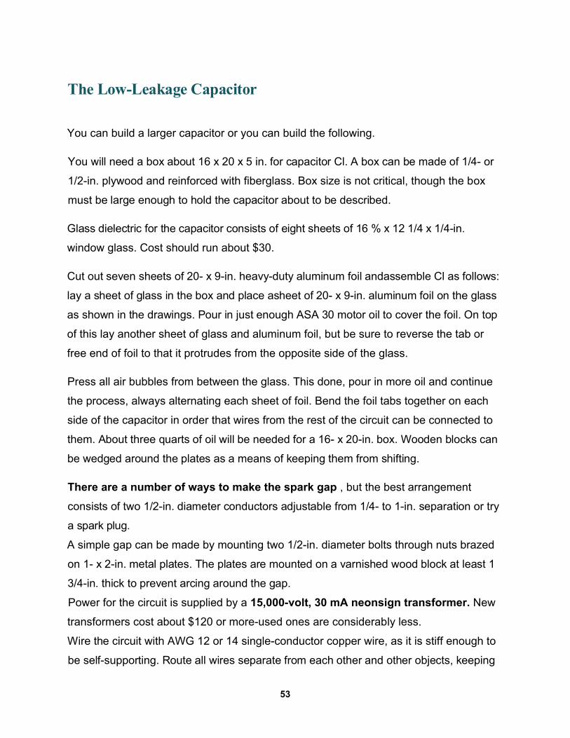
The Low-Leakage Capacitor
You can build a larger capacitor or you can build the following.
You will need a box about 16 x 20 x 5 in. for capacitor Cl. A box can be made of 1/4- or
1/2-in. plywood and reinforced with fiberglass. Box size is not critical, though the box
must be large enough to hold the capacitor about to be described.
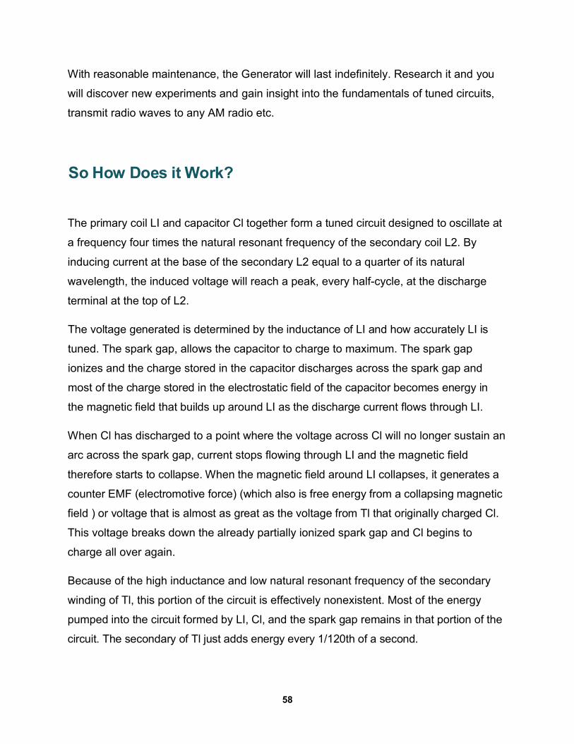
Glass dielectric for the capacitor consists of eight sheets of 16 % x 12 1/4 x 1/4-in.
window glass. Cost should run about $30.
Cut out seven sheets of 20- x 9-in. heavy-duty aluminum foil andassemble Cl as follows:
lay a sheet of glass in the box and place asheet of 20- x 9-in. aluminum foil on the glass
as shown in the drawings. Pour in just enough ASA 30 motor oil to cover the foil. On top
of this lay another sheet of glass and aluminum foil, but be sure to reverse the tab or
free end of foil to that it protrudes from the opposite side of the glass.
Press all air bubbles from between the glass. This done, pour in more oil and continue
the process, always alternating each sheet of foil. Bend the foil tabs together on each
side of the capacitor in order that wires from the rest of the circuit can be connected to
them. About three quarts of oil will be needed for a 16- x 20-in. box. Wooden blocks can
be wedged around the plates as a means of keeping them from shifting.
There are a number of ways to make the spark gap , but the best arrangement
consists of two 1/2-in. diameter conductors adjustable from 1/4- to 1-in. separation or try
a spark plug.
A simple gap can be made by mounting two 1/2-in. diameter bolts through nuts brazed
on 1- x 2-in. metal plates. The plates are mounted on a varnished wood block at least 1
3/4-in. thick to prevent arcing around the gap.
Power for the circuit is supplied by a 15,000-volt, 30 mA neonsign transformer. New
transformers cost about $120 or more-used ones are considerably less.
Wire the circuit with AWG 12 or 14 single-conductor copper wire, as it is stiff enough to
be self-supporting. Route all wires separate from each other and other objects, keeping
53
in mind that high voltages will be present throughout most of the circuit. Capacitor Cl is
wired into the circuit by atta ching wires directly to the aluminum foil tabs. Place
components according to drawings.
Operating the Generator
When the circuit is ready for testing, connect the ground wire from the bottom of the
secondary to a water pipe or telephone ground.
54
Tuning
If the spark-gap is operating, but either a weak discharge or none at all appears at the
top of L2, the coil will have to be tuned. This is accomplished by varying the number or
size of the aluminum foil sheets in Cl and by varying the effective turns on LI. It's easier
to begin tuning by varying the exposed area of the top sheet of aluminum foil and by
"tapping in" a few turns down from the top of the primary.
Maximum discharge generally will be reached with a total variation of no more than two
or three turns on coil LI and one full sheet of aluminum foil in Cl. If reducing the number
of turns in LI and changing the number of plates in Cl doesn't help, try adding several
turns to LI by splicing in additional wire.
An additional sheet of foil can be added to the capacitor, but another sheet of glass will
be needed also. It is best not to operate the Generator for more than 15 to 20 seconds
continuously without an equal time off, as the oil in the capacitor will start to break
down, allowing arcing to occur. But if you build our home made HV capacitors or use an
old microwave AC or DC capacitor you will get better results.
Remember to be careful. High voltage can kill and is much more powerful after it enters
a large capacitor, wear rubber gloves.
55
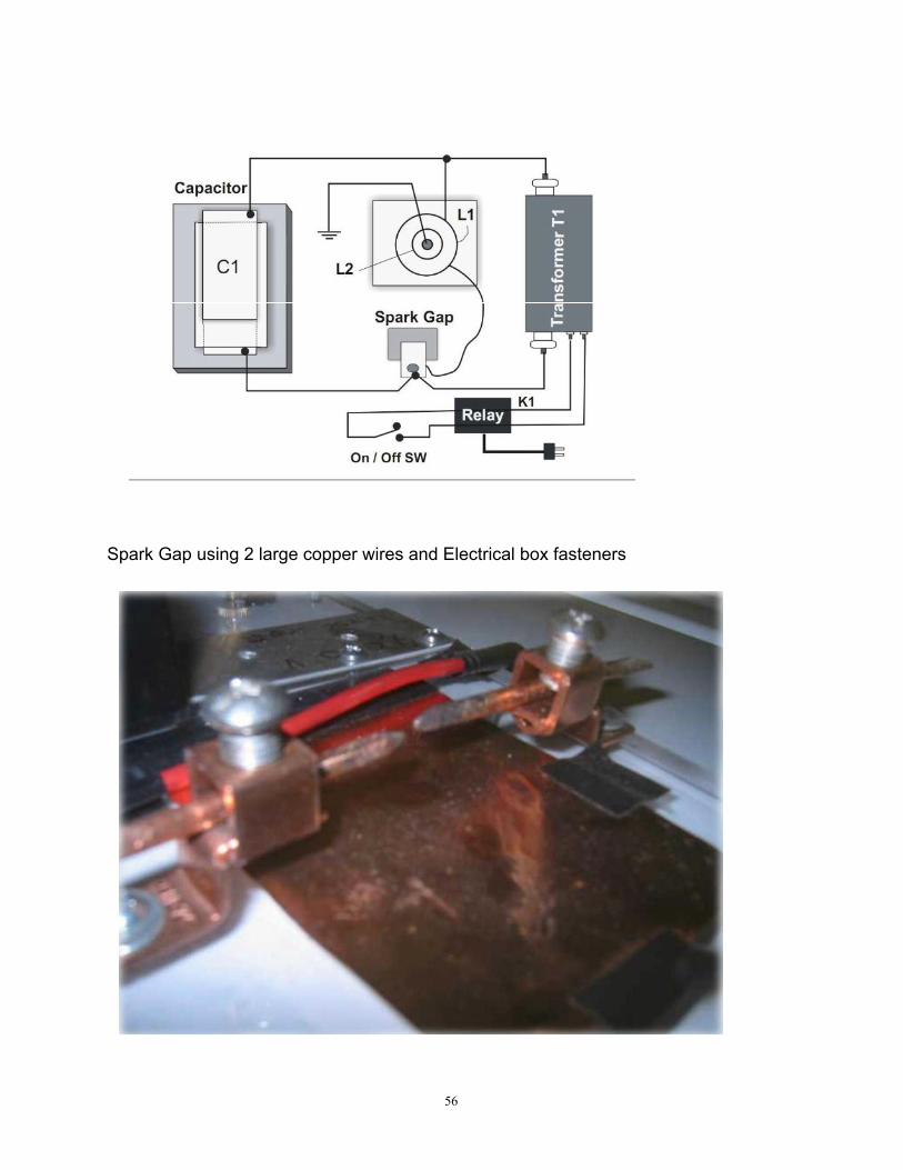
Spark Gap using 2 large copper wires and Electrical box fasteners
56
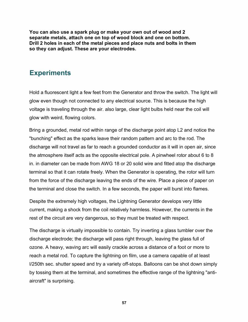
You can also use a spark plug or make your own out of wood and 2 separate metals, attach one on top of wood block and one on bottom. Drill 2 holes in each of the metal pieces and place nuts and bolts in them so they can adjust. These are your electrodes.
Experiments
Hold a fluorescent light a few feet from the Generator and throw the switch. The light will
glow even though not connected to any electrical source. This is because the high
voltage is traveling through the air. also large, clear light bulbs held near the coil will
glow with weird, flowing colors.
Bring a grounded, metal rod within range of the discharge point atop L2 and notice the
"bunching" effect as the sparks leave their random pattern and arc to the rod. The
discharge will not travel as far to reach a grounded conductor as it will in open air, since
the atmosphere itself acts as the opposite electrical pole. A pinwheel rotor about 6 to 8
in. in diameter can be made from AWG 18 or 20 solid wire and fitted atop the discharge
terminal so that it can rotate freely. When the Generator is operating, the rotor will turn
from the force of the discharge leaving the ends of the wire. Place a piece of paper on
the terminal and close the switch. In a few seconds, the paper will burst into flames.
Despite the extremely high voltages, the Lightning Generator develops very little
current, making a shock from the coil relatively harmless. However, the currents in the
rest of the circuit are very dangerous, so they must be treated with respect.
The discharge is virtually impossible to contain. Try inverting a glass tumbler over the
discharge electrode; the discharge will pass right through, leaving the glass full of
ozone. A heavy, waving arc will easily crackle across a distance of a foot or more to
reach a metal rod. To capture the lightning on film, use a camera capable of at least
l/250th sec. shutter speed and try a variety off-stops. Balloons can be shot down simply
by tossing them at the terminal, and sometimes the effective range of the lightning "anti-
aircraft" is surprising.
57
With reasonable maintenance, the Generator will last indefinitely. Research it and you
will discover new experiments and gain insight into the fundamentals of tuned circuits,
transmit radio waves to any AM radio etc.
So How Does it Work?
The primary coil LI and capacitor Cl together form a tuned circuit designed to oscillate at
a frequency four times the natural resonant frequency of the secondary coil L2. By
inducing current at the base of the secondary L2 equal to a quarter of its natural
wavelength, the induced voltage will reach a peak, every half-cycle, at the discharge
terminal at the top of L2.
The voltage generated is determined by the inductance of LI and how accurately LI is
tuned. The spark gap, allows the capacitor to charge to maximum. The spark gap
ionizes and the charge stored in the capacitor discharges across the spark gap and
most of the charge stored in the electrostatic field of the capacitor becomes energy in
the magnetic field that builds up around LI as the discharge current flows through LI.
When Cl has discharged to a point where the voltage across Cl will no longer sustain an
arc across the spark gap, current stops flowing through LI and the magnetic field
therefore starts to collapse. When the magnetic field around LI collapses, it generates a
counter EMF (electromotive force) (which also is free energy from a collapsing magnetic
field ) or voltage that is almost as great as the voltage from Tl that originally charged Cl.
This voltage breaks down the already partially ionized spark gap and Cl begins to
charge all over again.
Because of the high inductance and low natural resonant frequency of the secondary
winding of Tl, this portion of the circuit is effectively nonexistent. Most of the energy
pumped into the circuit formed by LI, Cl, and the spark gap remains in that portion of the
circuit. The secondary of Tl just adds energy every 1/120th of a second.
58
For best results, the oscillation frequency should about 120 kHz. As Cl recharges from
the magnetic field around LI, a point is again reached where the spark gap cannot be
sustained because all the energy is gone from the winding of LI. This means that the
magnetic field has collapsed completely. Once more Cl discharges, and current flow
again reverses through the spark gap and a magnetic field builds up around the coil LI.
With each cycle of charge and discharge the energy transferred is reduced and would
soon die out if energy weren't added by the secondary of Tl. This free energy from a
collapsing magnetic field can be used to recharge a battery or capcitor bank. Each
buildup and breakdown of the magnetic field induces a voltage in coil L2 which
discharges from the tip of L2 in the form of lightning-like flashes and streaks.
Construction Of The Capacitor
Aluminum Foil must be taped to the glass, Foil side up. With tabs protruding from the
opposite ends. In fig. 1-19 use 8 shts of window glass and seven shts of heavy duty
Aluminum foil or roofing foil. Cover each layer with oil. Baby oil, or without.
59

62
A multi-stack HV Capacitor using clear 4 mil mylar
63
Tesla Coil using a 4" PVC Pipe
64
15,000 volt Neon sign transformer
Relay Switches
65
Copper wire Spark Gap
66
Chapter 6The Dynamo-Electric Machine
One of the most famous of Tesla's inventions was his turbine design. In fact, his
bladeless turbine is still used in the modern world for many different things. It offers
significant advantages, particularly where fluid and semi-fluid substances need to be
pumped.
The lack of blades on the turbine means that it operates much more effectively than
bladed pumps. However, the design for this turbine was not unique to this device - it
also turns up in Tesla's design for his Dynamo-Electric Machine.
What Is the Dynamo-Electric Machine?The dynamo device designed by TesIa was much like his bladeless turbine. In fact, the
key element that set his turbine apart from others also defined his dynamo. This was
the general structure of the two devices - metal disks turning inside a box.
Strangely, the dynamo designed by TesIa was somewhat less advanced in design than
his alternating current generator design, for which he had become famous. However,
he took great pains to explain to the world why he had gone back to such a simple
device. The design that TesIa eventually created was based in large part on the original
Faraday dynamo.
67
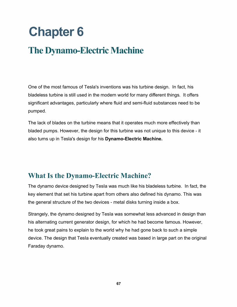
Tesla's Dynamo Design Tesla's Turbine Design
However, the inventor goes into detail concerning the changes that he made to the device
to improve its efficiency and power generating capabilities. In fact, he claims that his uni-
polar dynamo design was capable of creating a self-sustaining current, once activated by
an outside source. Below, you will find an image of Tesla's turbine, contrasted with an
image of his dynamo design.
Variations on the Faraday Design
There were several key ways in which Tesla's design varied from the one developed by
Faraday.
• Larger Magnet
In Faraday's original design, the magnet used was relatively small when
compared to the size of the copper disk. Tesia decided to use a much larger
magnet. In fact, it was larger than the copper disk itself, covering the entire
structure.
68
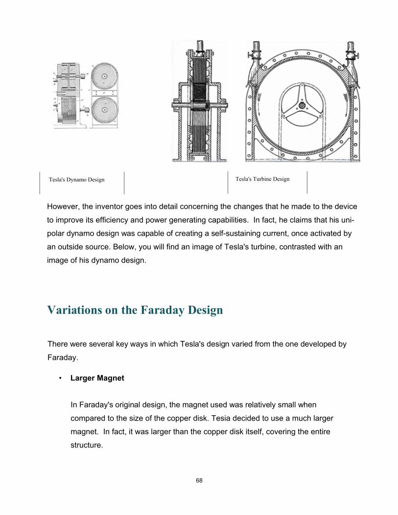
By using a magnet that completely covered the
copper disk, Tesia was able to achieve better
results than Faraday. In Faraday's original design,
only a small portion of the disk's surface was used
for current generation.
However, in Tesla's design, the entire surface
produced current, which boosted the total output of the device by a considerable
amount. However, there was another important advantage here.
• Spiral Sections
The second way in which Tesla's design differed is that he segmented his disk
with spiraling curves. These started in the center of the disk and radiated
outward to the edges.
The reason that Tesia used spirals radiating from the center of the disk to the
outer edges is that it encouraged the flow of current outward, which enabled him
to harness that current much more easily.
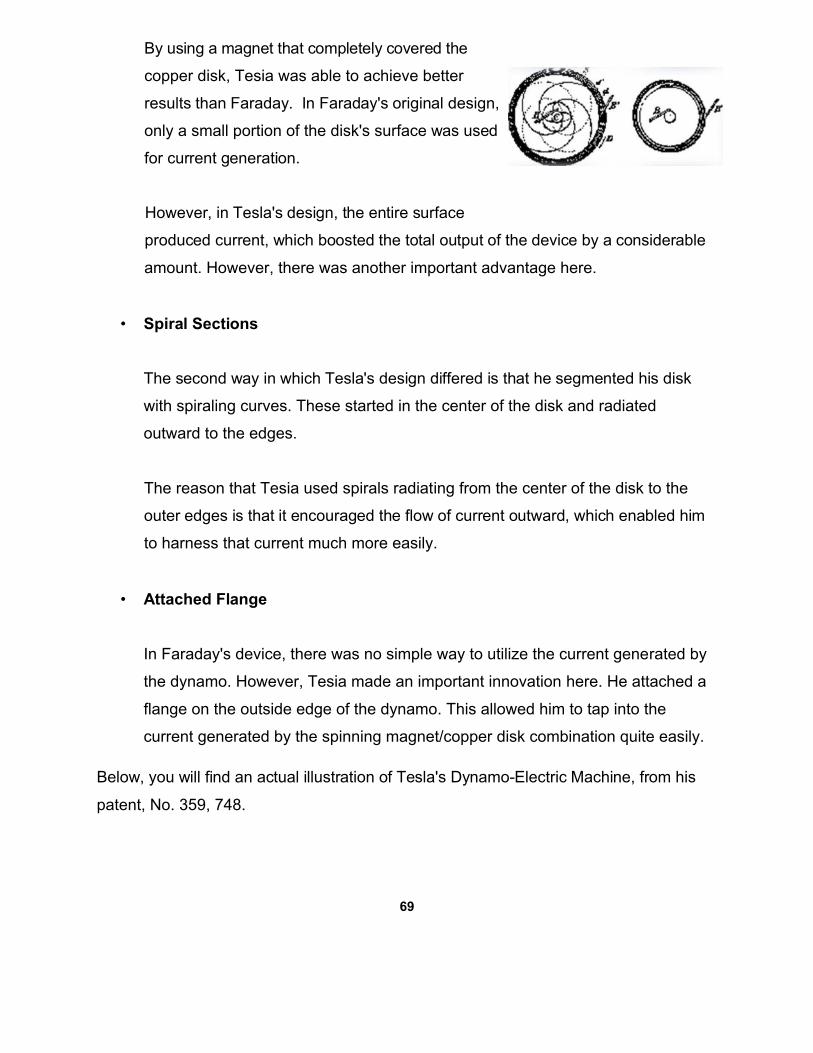
• Attached Flange
In Faraday's device, there was no simple way to utilize the current generated by
the dynamo. However, Tesia made an important innovation here. He attached a
flange on the outside edge of the dynamo. This allowed him to tap into the
current generated by the spinning magnet/copper disk combination quite easily.
Below, you will find an actual illustration of Tesla's Dynamo-Electric Machine, from his
patent, No. 359, 748.
69
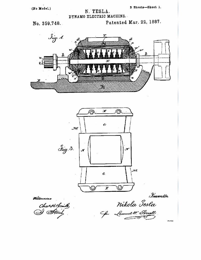
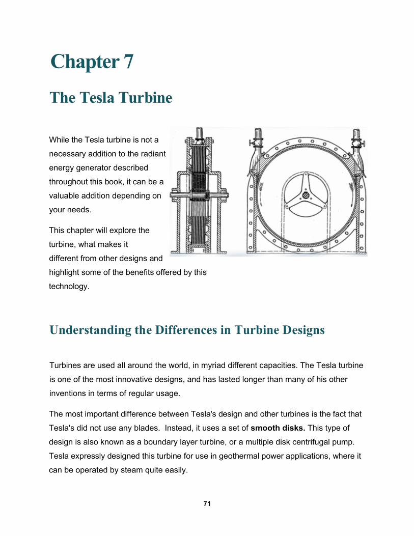
Chapter 7
The Tesla Turbine
While the Tesla turbine is not a
necessary addition to the radiant
energy generator described
throughout this book, it can be a
valuable addition depending on
your needs.
This chapter will explore the
turbine, what makes it
different from other designs and
highlight some of the benefits offered by this
technology.
Understanding the Differences in Turbine Designs
Turbines are used all around the world, in myriad different capacities. The Tesla turbine
is one of the most innovative designs, and has lasted longer than many of his other
inventions in terms of regular usage.
The most important difference between Tesla's design and other turbines is the fact that
Tesla's did not use any blades. Instead, it uses a set of smooth disks. This type of
design is also known as a boundary layer turbine, or a multiple disk centrifugal pump.
Tesla expressly designed this turbine for use in geothermal power applications, where it
can be operated by steam quite easily.
71
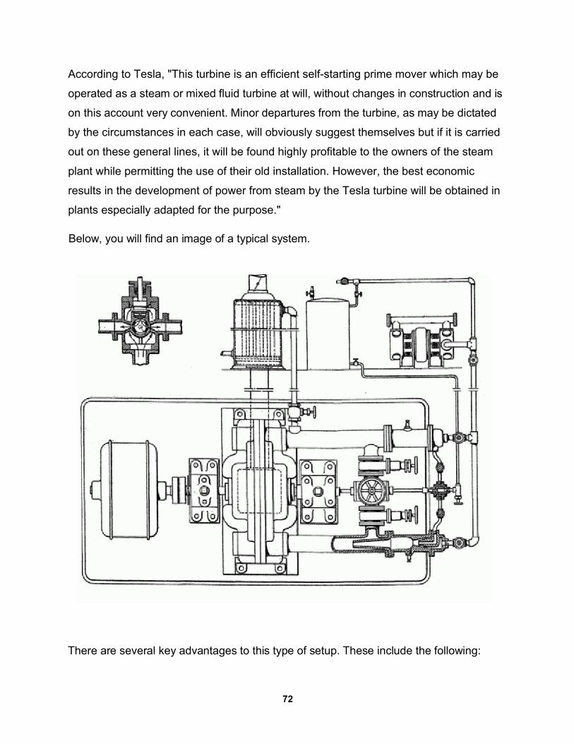
According to Tesla, "This turbine is an efficient self-starting prime mover which may be
operated as a steam or mixed fluid turbine at will, without changes in construction and is
on this account very convenient. Minor departures from the turbine, as may be dictated
by the circumstances in each case, will obviously suggest themselves but if it is carried
out on these general lines, it will be found highly profitable to the owners of the steam
plant while permitting the use of their old installation. However, the best economic
results in the development of power from steam by the Tesla turbine will be obtained in
plants especially adapted for the purpose."
Below, you will find an image of a typical system.
There are several key advantages to this type of setup. These include the following:
72
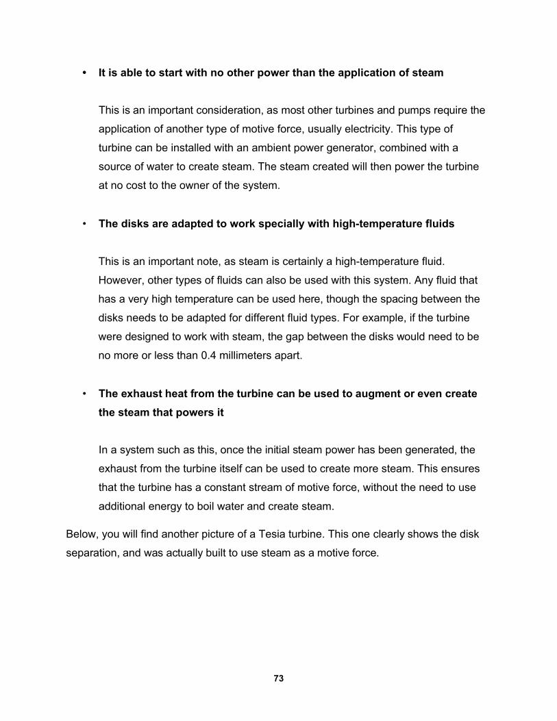
• It is able to start with no other power than the application of steam
This is an important consideration, as most other turbines and pumps require the
application of another type of motive force, usually electricity. This type of
turbine can be installed with an ambient power generator, combined with a
source of water to create steam. The steam created will then power the turbine
at no cost to the owner of the system.
• The disks are adapted to work specially with high-temperature fluids
This is an important note, as steam is certainly a high-temperature fluid.
However, other types of fluids can also be used with this system. Any fluid that
has a very high temperature can be used here, though the spacing between the
disks needs to be adapted for different fluid types. For example, if the turbine
were designed to work with steam, the gap between the disks would need to be
no more or less than 0.4 millimeters apart.
• The exhaust heat from the turbine can be used to augment or even create
the steam that powers it
In a system such as this, once the initial steam power has been generated, the
exhaust from the turbine itself can be used to create more steam. This ensures
that the turbine has a constant stream of motive force, without the need to use
additional energy to boil water and create steam.
Below, you will find another picture of a Tesia turbine. This one clearly shows the disk
separation, and was actually built to use steam as a motive force.
73
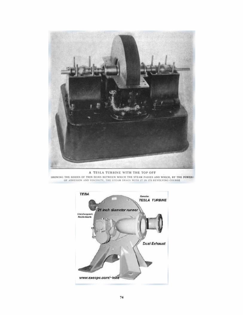
74
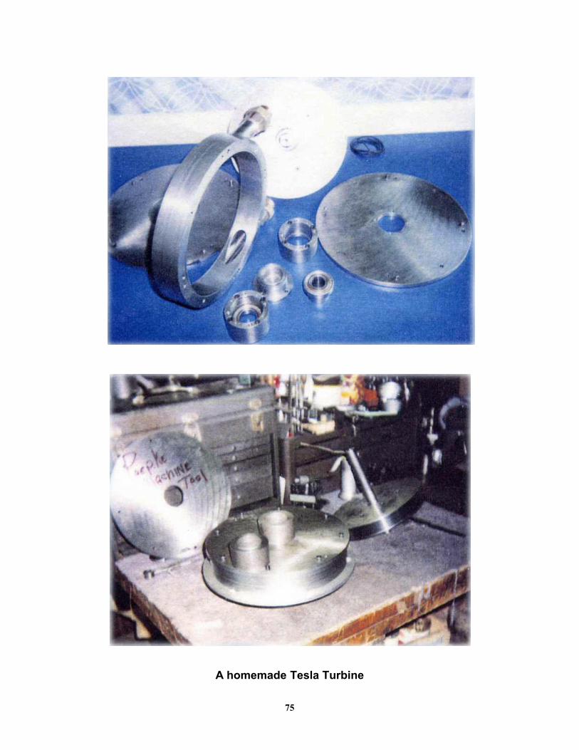
A homemade Tesla Turbine
75
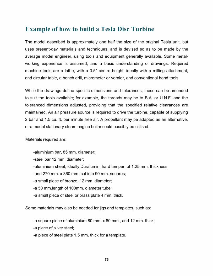
Example of how to build a Tesla Disc Turbine
The model described is approximately one half the size of the original Tesla unit, but
uses present-day materials and techniques, and is devised so as to be made by the
average model engineer, using tools and equipment generally available. Some metal-
working experience is assumed, and a basic understanding of drawings. Required
machine tools are a lathe, with a 3.5" centre height, ideally with a milling attachment,
and circular table, a bench drill, micrometer or vernier, and conventional hand tools.
While the drawings define specific dimensions and tolerances, these can be amended
to suit the tools available; for example, the threads may be to B.A. or U.N.F. and the
toleranced dimensions adjusted, providing that the specified relative clearances are
maintained. An air pressure source is required to drive the turbine, capable of supplying
2 bar and 1.5 cu. ft. per minute free air. A propellant may be adapted as an alternative,
or a model stationary steam engine boiler could possibly be utilised.
Materials required are:
-aluminium bar, 85 mm. diameter;
-steel bar 12 mm. diameter;
-aluminium sheet, ideally Duralumin, hard temper, of 1.25 mm. thickness
-and 270 mm. x 360 mm. cut into 90 mm. squares;
-a small piece of bronze, 12 mm. diameter;
-a 50 mm.length of 100mm. diameter tube;
-a small piece of steel or brass plate 4 mm. thick.
Some materials may also be needed for jigs and templates, such as:
-a square piece of aluminium 80 mm. x 80 mm., and 12 mm. thick;
-a piece of silver steel;
-a piece of steel plate 1.5 mm. thick for a template.
76
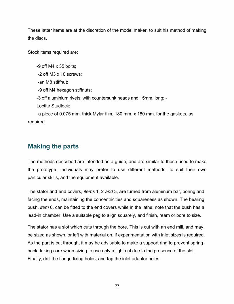
These latter items are at the discretion of the model maker, to suit his method of making
the discs.
Stock items required are:
-9 off M4 x 35 bolts;
-2 off M3 x 10 screws;
-an M8 stiffnut;
-9 off M4 hexagon stiffnuts;
-3 off aluminium rivets, with countersunk heads and 15mm. long; -
Loctite Studlock;
-a piece of 0.075 mm. thick Mylar film, 180 mm. x 180 mm. for the gaskets, as
required.
Making the parts
The methods described are intended as a guide, and are similar to those used to make
the prototype. Individuals may prefer to use different methods, to suit their own
particular skills, and the equipment available.
The stator and end covers, items 1, 2 and 3, are turned from aluminum bar, boring and
facing the ends, maintaining the concentricities and squareness as shown. The bearing
bush, item 6, can be fitted to the end covers while in the lathe; note that the bush has a
lead-in chamber. Use a suitable peg to align squarely, and finish, ream or bore to size.
The stator has a slot which cuts through the bore. This is cut with an end mill, and may
be sized as shown, or left with material on, if experimentation with inlet sizes is required.
As the part is cut through, it may be advisable to make a support ring to prevent spring-
back, taking care when sizing to use only a light cut due to the presence of the slot.
Finally, drill the flange fixing holes, and tap the inlet adaptor holes.
77
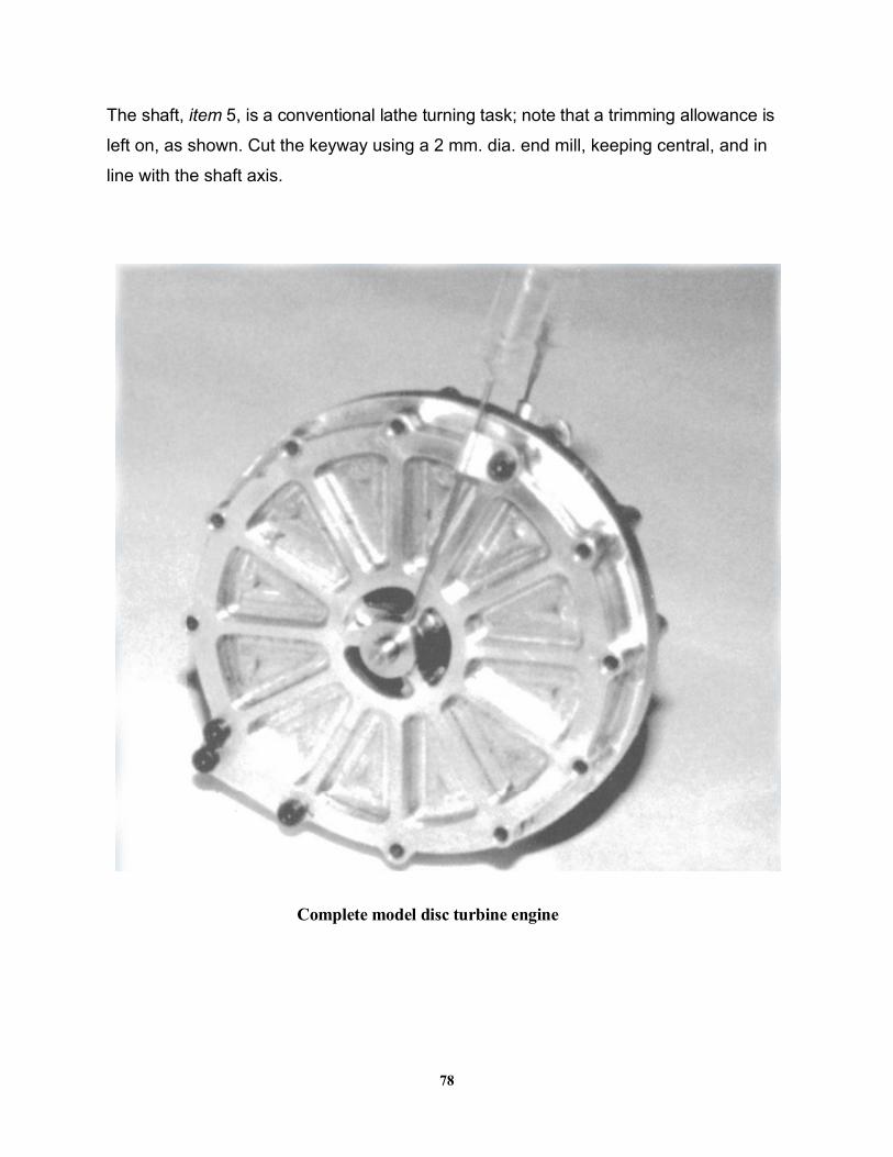
The shaft, item 5, is a conventional lathe turning task; note that a trimming allowance is
left on, as shown. Cut the keyway using a 2 mm. dia. end mill, keeping central, and in
line with the shaft axis.
Complete model disc turbine engine
78
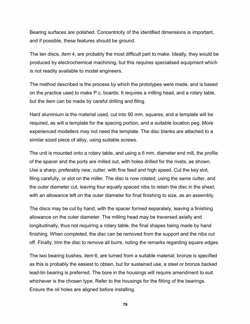
Bearing surfaces are polished. Concentricity of the identified dimensions is important,
and if possible, these features should be ground.
The ten discs, item 4, are probably the most difficult part to make. Ideally, they would be
produced by electrochemical machining, but this requires specialised equipment which
is not readily available to model engineers.
The method described is the process by which the prototypes were made, and is based
on the practice used to make P.c. boards. It requires a milling head, and a rotary table,
but the item can be made by careful drilling and filing.
Hard aluminium is the material used, cut into 90 mm. squares, and a template will be
required, as will a template for the spacing portion, and a suitable location peg. More
experienced modellers may not need the template. The disc blanks are attached to a
similar sized piece of alloy, using suitable screws.
The unit is mounted onto a rotary table, and using a 6 mm. diameter end mill, the profile
of the spacer and the ports are milled out, with holes drilled for the rivets, as shown.
Use a sharp, preferably new, cutter, with fine feed and high speed. Cut the key slot,
filing carefully, or slot on the miller. The disc is now rotated, using the same cutter, and
the outer diameter cut, leaving four equally spaced nibs to retain the disc in the sheet,
with an allowance left on the outer diameter for final finishing to size, as an assembly.
The discs may be cut by hand, with the spacer formed separately, leaving a finishing
allowance on the outer diameter. The milling head may be traversed axially and
longitudinally, thus not requiring a rotary table, the final shapes being made by hand
finishing. When completed, the disc can be removed from the support and the nibs cut
off. Finally, trim the disc to remove all burrs, noting the remarks regarding square edges.
The two bearing bushes, item 6, are turned from a suitable material; bronze is specified
as this is probably the easiest to obtain, but for sustained use, a steel or bronze backed
lead-tin bearing is preferred. The bore in the housings will require amendment to suit
whichever is the chosen type. Refer to the housings for the fitting of the bearings.
Ensure the oil holes are aligned before installing.
79
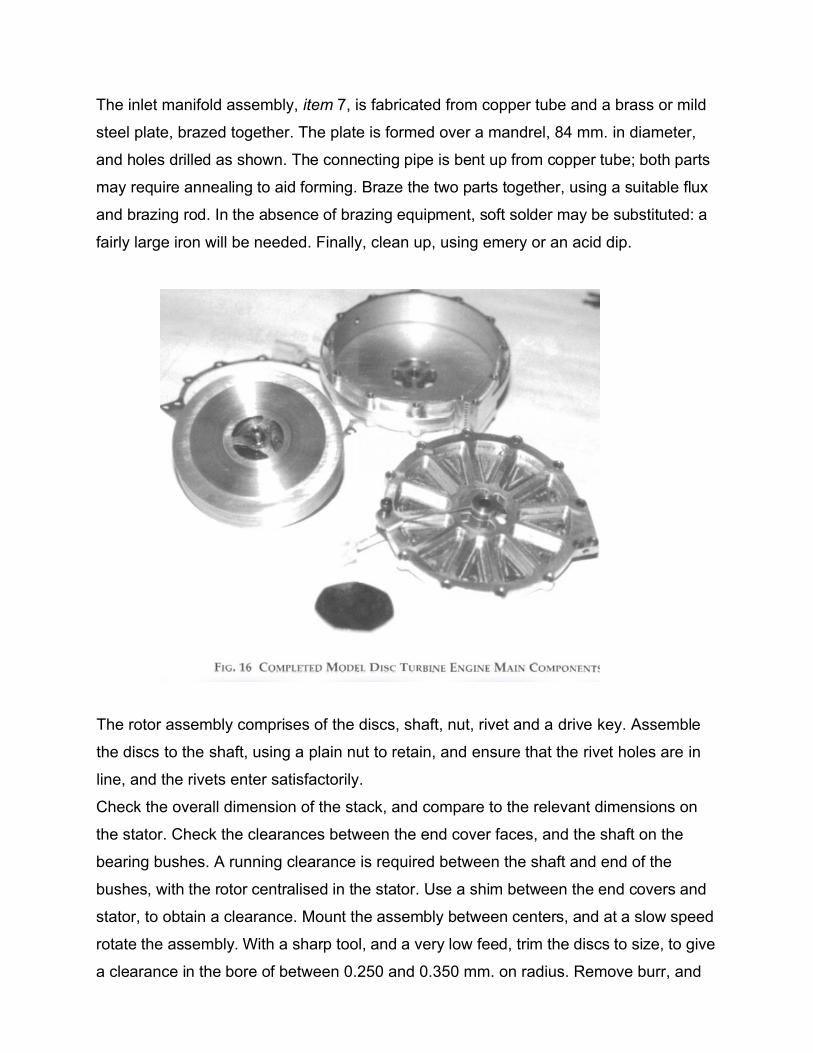
The inlet manifold assembly, item 7, is fabricated from copper tube and a brass or mild
steel plate, brazed together. The plate is formed over a mandrel, 84 mm. in diameter,
and holes drilled as shown. The connecting pipe is bent up from copper tube; both parts
may require annealing to aid forming. Braze the two parts together, using a suitable flux
and brazing rod. In the absence of brazing equipment, soft solder may be substituted: a
fairly large iron will be needed. Finally, clean up, using emery or an acid dip.
The rotor assembly comprises of the discs, shaft, nut, rivet and a drive key. Assemble
the discs to the shaft, using a plain nut to retain, and ensure that the rivet holes are in
line, and the rivets enter satisfactorily.
Check the overall dimension of the stack, and compare to the relevant dimensions on
the stator. Check the clearances between the end cover faces, and the shaft on the
bearing bushes. A running clearance is required between the shaft and end of the
bushes, with the rotor centralised in the stator. Use a shim between the end covers and
stator, to obtain a clearance. Mount the assembly between centers, and at a slow speed
rotate the assembly. With a sharp tool, and a very low feed, trim the discs to size, to give
a clearance in the bore of between 0.250 and 0.350 mm. on radius. Remove burr, and
check for run-out. If more than 0.05 mm, adjust the side clearance to accommodate. A
large slide clearance will not be detrimental to running, but will affect the output
performance. Close the rivets, making sure they are flush to under flush. Remove the
nut, and replace with a stiff nut.
Check for static balance, drilling countersunk holes partially into the end discs until
satisfactory. Balance is important as the turbine rotates at high speed. Assemble into
the stator and end covers, tightening the fastenings as specified, and build on the intake
manifold. Lubricate the bearings copiously, and rotate by hand, checking carefully for
any tight spots or apparent foul points.
Place between centres and with the housing supported by the cross-slide and at a slow
speed, rotate the turbine, gradually increasing speed up to about 1000 RP.M. Watch for
any tightness or increase in temperature. Run for 5 minutes, ensuring the bearings are
kept well lubricated. Finally, when satisfied, remove from the lathe.
Testing
When satisfied that the unit is turning freely, with no tightness or temperature rise, the
unit can be tested using compressed air. This should be done initially, regardless of the
medium to be used eventually.
Using a flexible hose, connect to an air source, attaching the hose to the turbine with a
hose clip. Between the turbine and the air supply, close to the turbine, provide an onloff
valve, preferably of the ball type; for temporary use only, the hose may be squeezed in a
vice, or by clamps.
Place a guard over the turbine, and ensure that the exhaust ports are clear of
obstruction. Check the air pressure, which must not exceed 2 bar, and slowly open the
valve. The turbine will begin to rotate, and as the flow is increased, the speed will build
up.
81
Run for no more than two minutes, stop, check the housing temperature. If cool to
slightly warm, re-open the valve and continue running. At around 1.75 bar and 1.5 dm,
the turbine will attain a shaft speed of 20,000 RP.M. At all times ensure a supply of oil to
the bearings, and continually monitor the housing temperature. It should be noted that
the prototype attained a speed of approximately 50,000 RP.M. under no-load
conditions; hence it is advised that a brake or dynometer be provided on the shaft.
Upon conclusion of a satisfactory operation on air, an alternative medium can be used
to operate the turbine, such as steam from a model boiler. This model is not suitable for
use with hot gas, such as is obtained by burning fuel in a suitable combustor.
At all times, ensure a suitable guard is in place, and observe sensible precautions when
operating in the presence of other people.
This is a unique machine, and will provide plenty of scope for experimentation and
development by the maker.
Below you will find some drawings (reduced from full size originals) to help you better
understand the process.
82
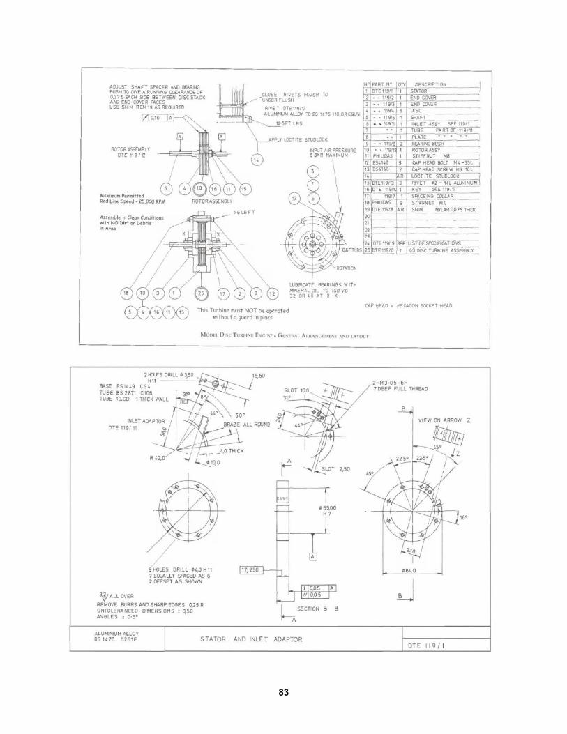
83
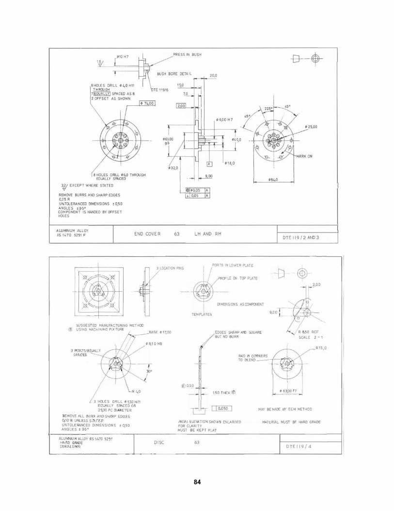
84
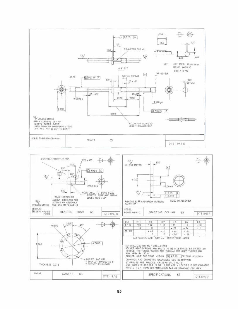
85
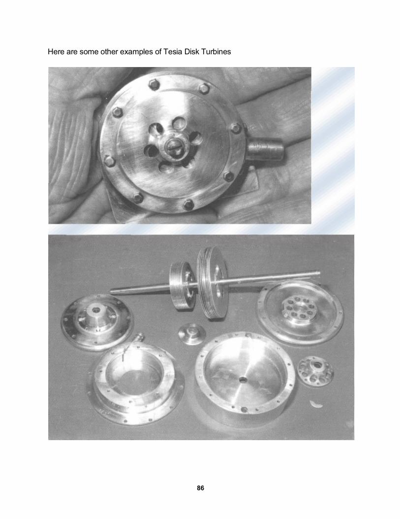
Here are some other examples of Tesia Disk Turbines
86
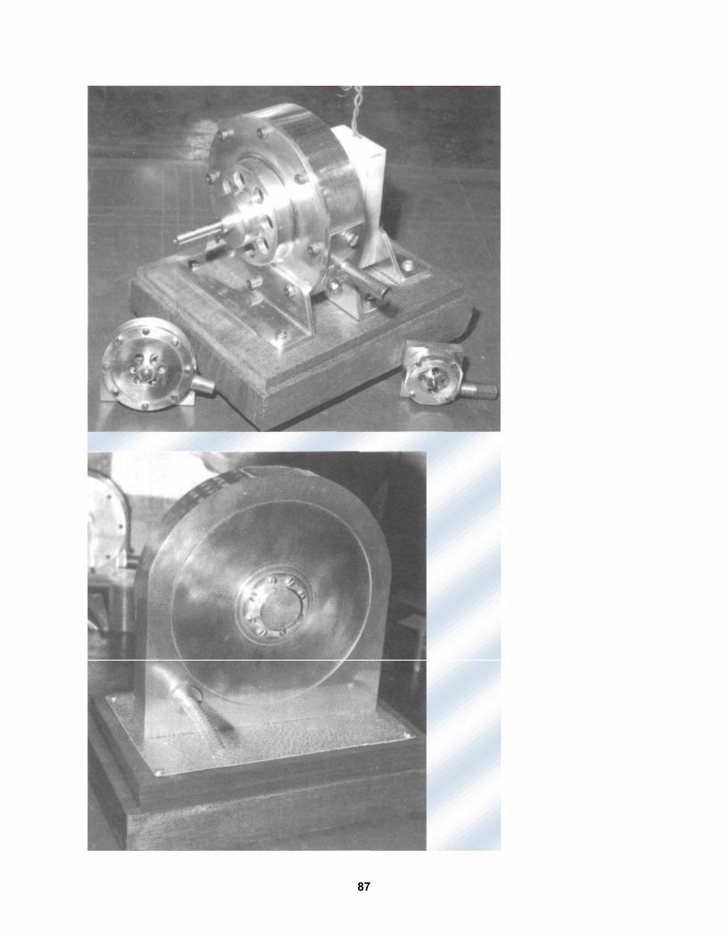
87
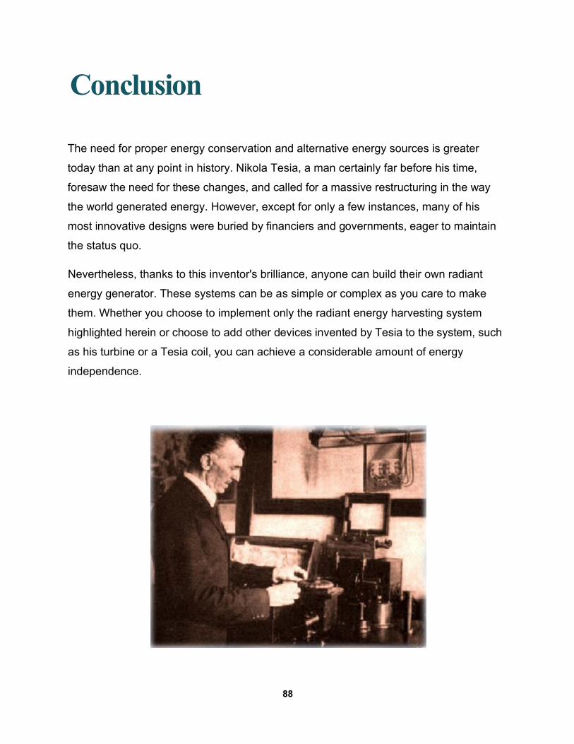
Conclusion
The need for proper energy conservation and alternative energy sources is greater
today than at any point in history. Nikola Tesia, a man certainly far before his time,
foresaw the need for these changes, and called for a massive restructuring in the way
the world generated energy. However, except for only a few instances, many of his
most innovative designs were buried by financiers and governments, eager to maintain
the status quo.
Nevertheless, thanks to this inventor's brilliance, anyone can build their own radiant
energy generator. These systems can be as simple or complex as you care to make
them. Whether you choose to implement only the radiant energy harvesting system
highlighted herein or choose to add other devices invented by Tesia to the system, such
as his turbine or a Tesia coil, you can achieve a considerable amount of energy
independence.
88
Appendix
On the following pages, you will find reproductions of Tesla's patents for the devices
listed within this book. These can be excellent sources of further information, but they
will also give you a glimpse into the mind of the man, himself.
89
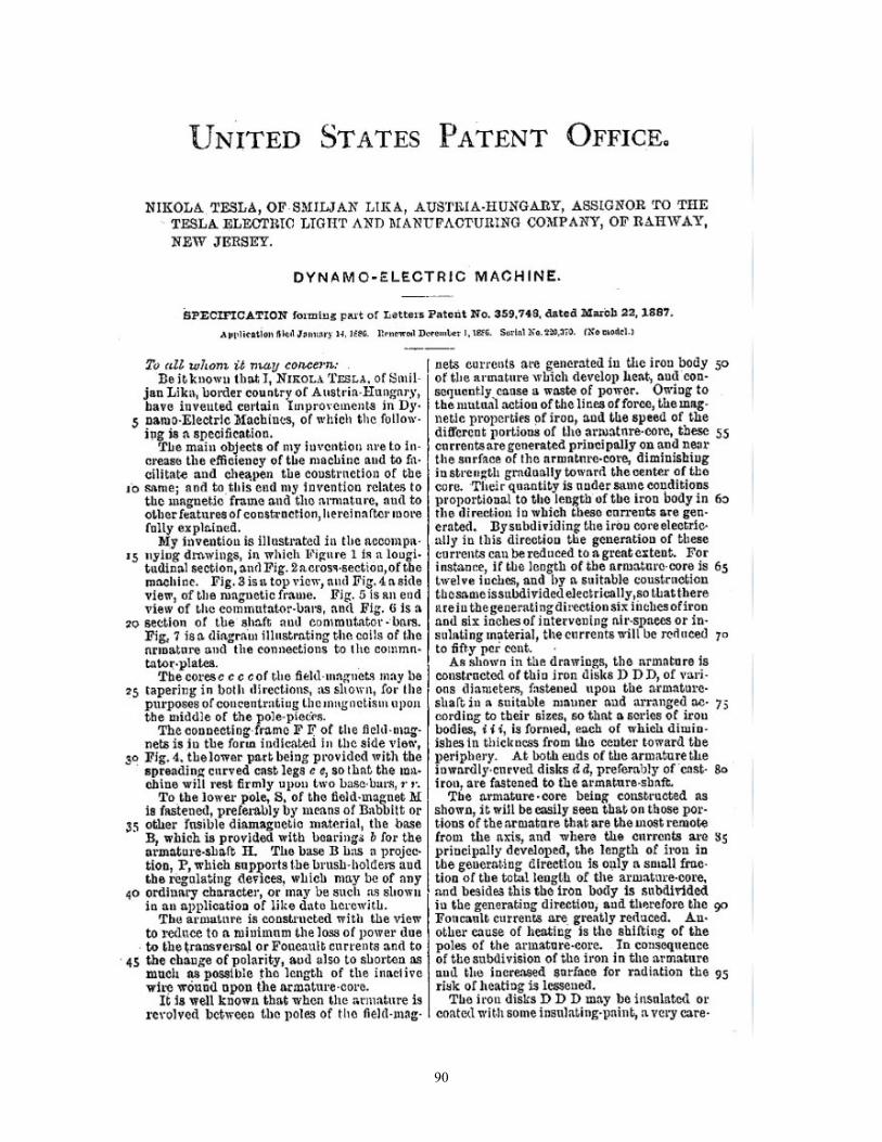
90
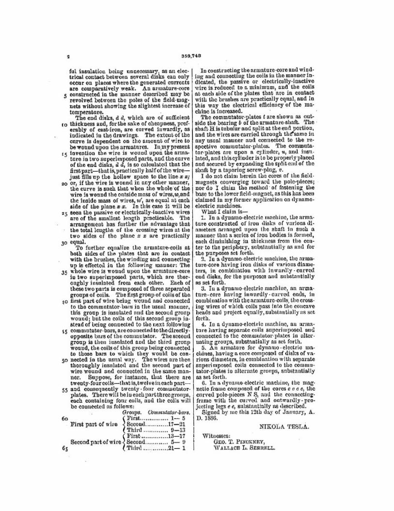
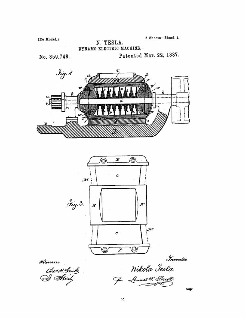
92
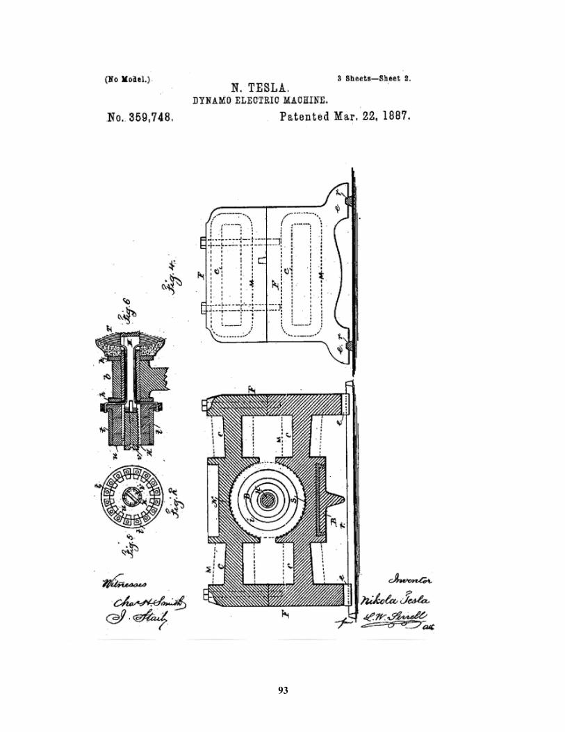
93
94
95
96
97
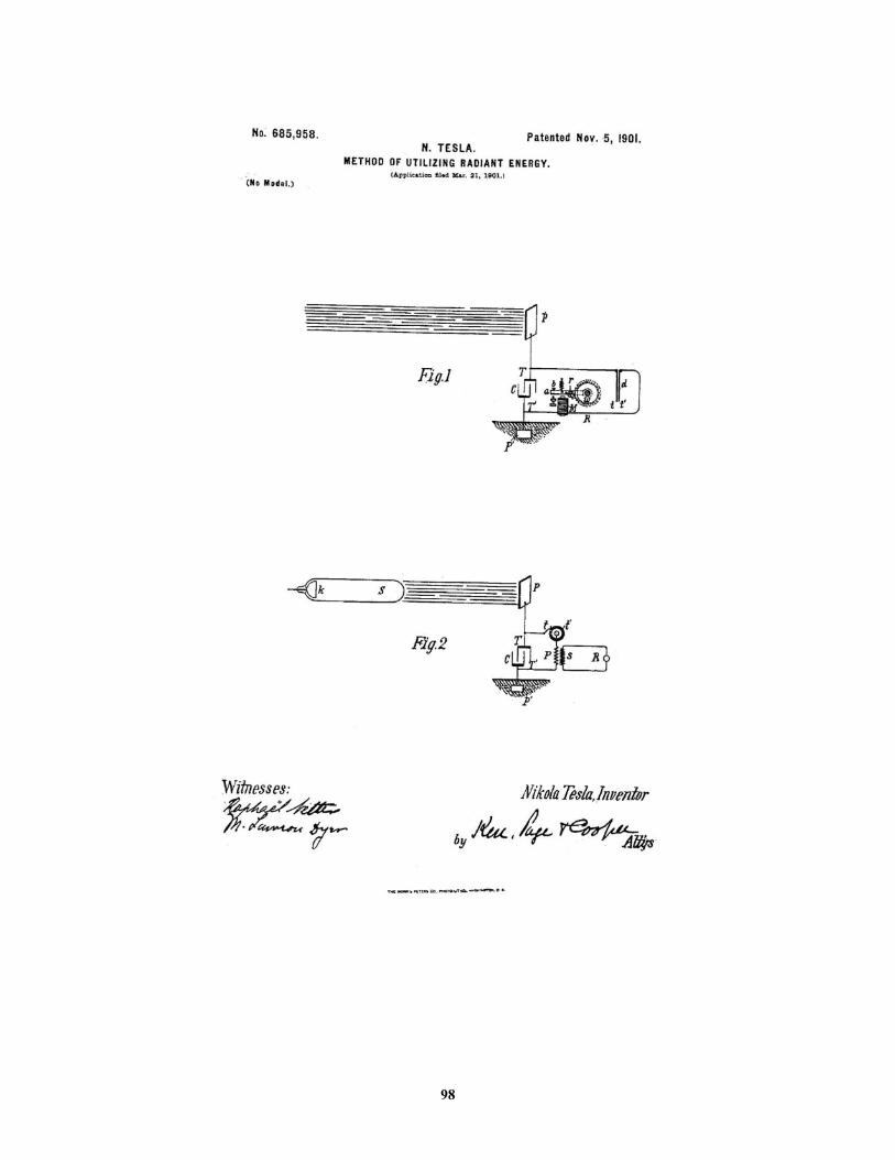
98
100
101

102
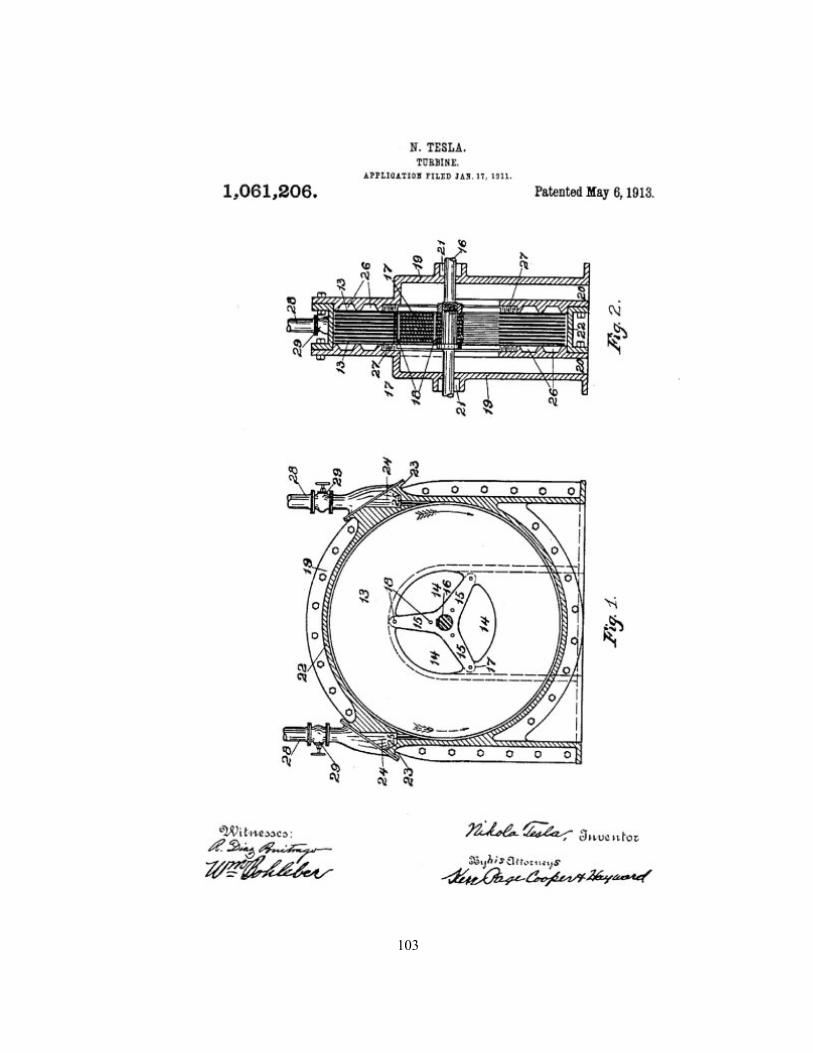
103
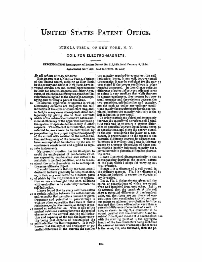
104
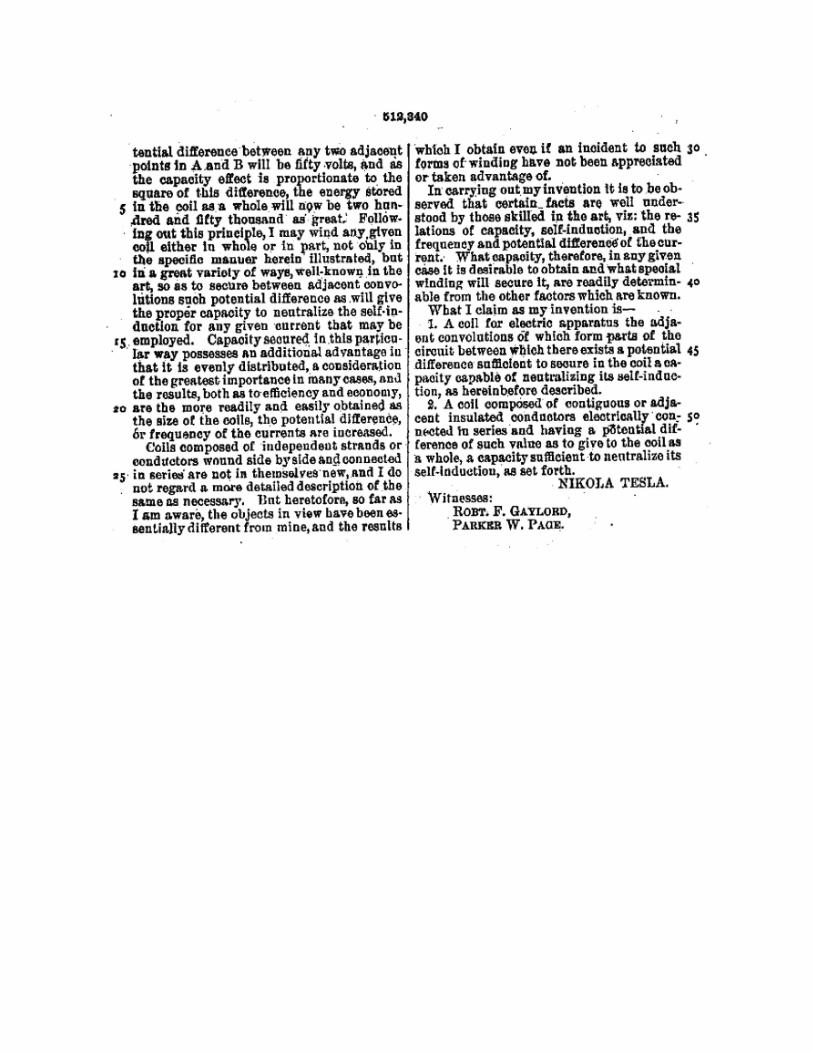
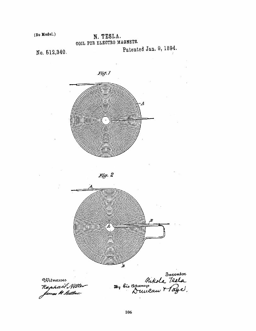
106
The Tesla Legacy Free energy for everyone! Nicola Tesla dreamt about it. Do the scientists and electrical
engineers have the technical know-how to make Nicola Tesla's dream a realization? The
principle of free energy was already given to us by Tesla more than a century ago. It is
just a matter of improving it and developing a new electrical distribution system
designed for free energy program.
Free radiant energy system is a device and technique that could make us harness
energy from the sky or from the ground. This free energy could be transformed into
usable electricity so that we do not have to pay electricity anymore.
The light of human progress is not a dim glow that gradually becomes more luminous
with time. The panorama of human evolution is illumined by sudden bursts of dazzling
brilliance in intellectual accomplishments that throw their beams far ahead to give us a
glimpse of the distant future, that we may more correctly guide our wavering steps
today.
Tesla, by virtue of the amazing discoveries and inventions which he showered on the
world, becomes one of the most resplendent flashes that has ever brightened the scroll
of human advancement.
Tesla created the modern era; he was unquestionably one of the world's greatest
geniuses.
At a time when electricity was considered almost an occult force, and was looked upon
with terror-stricken awe and respect, Tesla penetrated deeply into its mysteries and
performed so many marvelous feats with it that, to the world, he became a master
magician with an unlimited repertoire of scientific legerdemain so spectacular that it
made the accomplishments of most of the inventors of his day seem like the work of
toy-tinkers.
Tesla was an inventor, but he was much more than a producer of new devices: he was a
discoverer of new principles, opening many new empires of knowledge which even
107
today have been only partly explored. In a single mighty burst of invention he created
the world of power of today.
He brought into being our electrical power era, the rock bottom foundation on which the
industrial system of the entire world is built; he gave us our mass-production system, for
without his motors and currents it could not exist; he created the race of robots, the
electrical mechanical men that are replacing human labor; he gave us every essential of
modern radio; he invented the radar forty years before its use in World War II; he gave
us our modern neon and other forms of gaseous-tube lighting; he gave us our
fluorescent lighting; he gave us the high frequency currents which are performing their
electronic wonders throughout the industrial and medical worlds; he gave us remote
control by wireless etc. And these discoveries are merely the inventions made by the
master mind of Tesla which have thus far been utilized - scores of others remain still
unused.
Free energy technology is here, now. It offers the world pollution-free, energy
abundance for everyone, everywhere. It is up to us to benefit from the rivers of energy
that Nikola Tesla was talking about.
Accept the challenge to be among the ones who try!
108
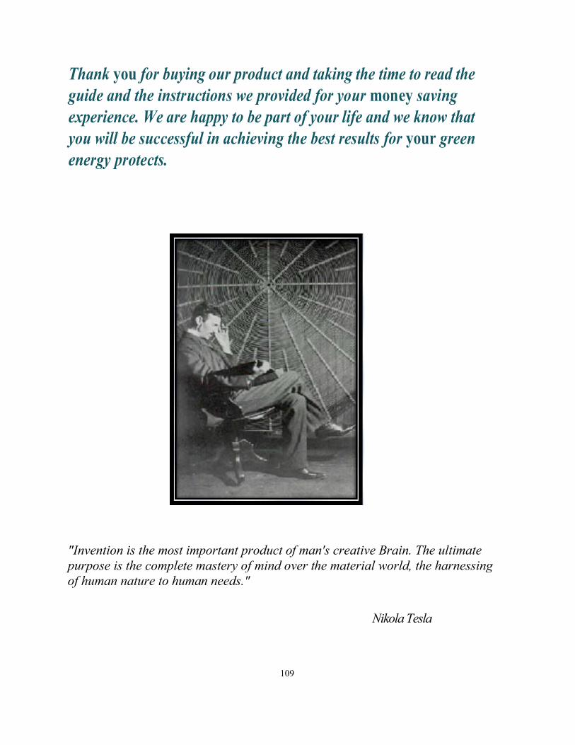
Thank you for buying our product and taking the time to read theguide and the instructions we provided for your money saving experience. We are happy to be part of your life and we know that you will be successful in achieving the best results for your green energy protects.
"Invention is the most important product of man's creative Brain. The ultimate purpose is the complete mastery of mind over the material world, the harnessing of human nature to human needs."
Nikola Tesla
109