the transervo by yamaha ! stepping motor single-axis ... · the transervo by yamaha ! stepping...
TRANSCRIPT

The TRANSERVO by YAMAHA !
Stepping motor single-axis robots
that break all the old rules !
YAMAHA Single-Axis Robots
New Product information
Stepping Servo (SS04 / SSC04 / SS05 / SSC05 / SS05H / SSC05H)
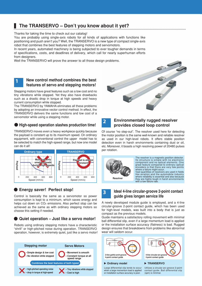
Environmentally rugged resolver provides closed loop control
Of course “no step-out”. The resolver used here for detecting the motor position is the same well-known and reliable resolver as used in our high-level robots. It offers stable position detection even in harsh environments containing dust or oil, etc. Moreover, it boasts a high resolving power of 20480 pulses per rotation.
Ideal 4-line circular-groove 2-point contact guide gives longen service life
A newly developed module guide is employed, and a 4-line circular-groove 2-point contact guide, which has been used for high-level models, was built into a body that is just as compact as the previous models. Guide maintains a satisfactory rolling movement with minimal ball differential slip, even if a large momentum load is applied or the installation surface accuracy (flatness) is bad. Rugged design ensures that breakdowns from problems like abnormal wear will seldom occur.
New control method combines the bestfeatures of servo and stepping motors!
Stepping motors have great features such as a low cost and no tiny vibrations while stopped. Yet they also have drawbacks such as a drastic drop in torque at high speeds and heavy current consumption while stopped.The TRANSERVO by YAMAHA eliminates all these problems by adopting an innovative vector control method. In effect, the TRANSERVO delivers the same functions and low cost of a servomotor while using a stepping motor.
High-speed operation slashes production time!
TRANSERVO moves even a heavy workpiece quickly because the payload is constant up to its maximum speed. On ordinary equipment, with conventional control the upper model has to be selected to match the high-speed range, but now one model can do it all!
Energy saver! Perfect stop!
Control is basically the same as a servomotor so power consumption is kept to a minimum, which saves energy and helps cut down on CO2 emissions. Also perfect stop can be achieved as the same as with ordinary stepping motors so choose this setting if needed.
Quiet operation – Just like a servo motor!
Robots using ordinary stepping motors have a characteristic “shrill” or high-pitched noise during operation. TRANSERVO operation, however, is extremely quiet, just like a servo motor!
Stepping motor Servo Motors
• Simple design & low cost• No vibration while stopped
• Movement is smooth• Constant torque at all speed range
• high-pitched operating noise
• drop in torque at high-speed• Tiny vibrations while stopped• Cost is high
Combines the best features of both types! Ordinary model
Large differential slip tends to occur when a large momentum load is applied or installation surface accuracy is poor.
TRANSERVO
Utilizes a circular-arc-groove 2-point contact guide. Ball differential slip (spin) is minimal.
2-line gothic-arch-groove 4-point contact guide
4-line circular-arc-groove 2-point contact guide
Speed (mm/s) 200 400 600 8000
Speed (mm/s) 200 400 600 8000
Ordinary type TRANSERVO
Resolver
The resolver is a magnetic position detector. Its structure is simple with no electronic component and no optical elements. One great feature compared to ordinary optical encoders is that there are very few points where a failure might occur. Vast quantities of resolvers are used in fields like aviation and the automobile industry where reliability is essential and also because they are highly tough in harsh environments with a low failure rate.
The TRANSERVO – Don’t you know about it yet?
Thanks for taking the time to check out our catalog!You are probably using single-axis robots for all kinds of applications with functions like positioning and push aren’t you? Well, the TRANSERVO is a new type of compact single-axis robot that combines the best features of stepping motors and servomotors.In recent years, automated machinery is being subjected to ever tougher demands in terms of specifications, costs, and deadlines of delivery, which call for nearly superhuman efforts from designers. Well the TRANSERVO will prove the answer to all those design problems.
Paylo
ad
Paylo
ad
Payload is always constant!
Payload is always constant!
Must use only small payloads
during high speeds
Must use only small payloads
during high speeds
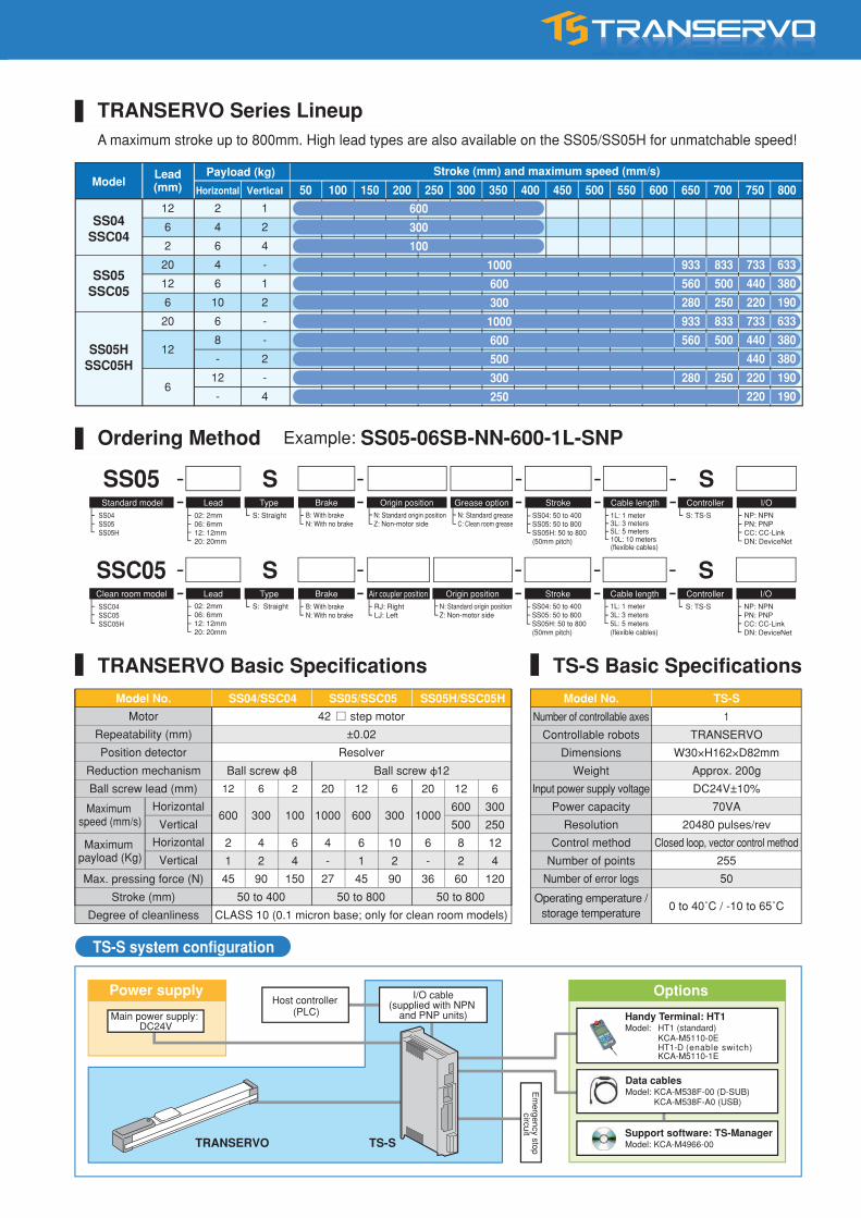
TS-S system configuration
Main power supply: DC24V
TRANSERVO TS-S
Host controller (PLC)
Em
ergency stop circuit
OptionsPower supply
Ordering Method Example: SS05-06SB-NN-600-1L-SNP
TRANSERVO Basic Specifications TS-S Basic Specifications
SS05 S S02: 2mm06: 6mm12: 12mm20: 20mm
02: 2mm06: 6mm12: 12mm20: 20mm
SSC05 S SSSC04SSC05SSC05H
Handy Terminal: HT1Model: HT1 (standard) KCA-M5110-0E HT1-D (enable switch) KCA-M5110-1E
Support software: TS-ManagerModel: KCA-M4966-00
Data cablesModel: KCA-M538F-00 (D-SUB) KCA-M538F-A0 (USB)
I/O cable(supplied with NPN
and PNP units)
50 100 150 200 250 300 350 400 450 500 550 600 650 700 750 800Vertical
12 6 2 20 12 6 20 12 6
600 300 100 1000 600 300 1000
600 300
500 250
2 4 6 4 6 10 6 8 12
1 2 4 - 1 2 - 2 4
45 90 150 27 45 90 36 60 120
50 to 400 50 to 800 50 to 800
600
300
100
933
560
280
933
560
280
833
500
250
833
500
250
1000
600
300
1000
600
500
300
250
733
440
220
733
440
440
220
220
633
380
190
633
380
380
190
190
SS04SSC04
SS05SSC05
SS05HSSC05H
12
6
2
20
12
6
20
12
6
2
4
6
4
6
10
6
8
-
12
-
1
2
4
-
1
2
-
-
2
-
4
Maximum payload (Kg)
Maximum speed (mm/s)
TRANSERVO Series LineupA maximum stroke up to 800mm. High lead types are also available on the SS05/SS05H for unmatchable speed!
Lead(mm)
Payload (kg)
HorizontalModel
Stroke (mm) and maximum speed (mm/s)
Standard model
Clean room model
Lead
Lead
Type
Type
Brake
Brake Air coupler position
Origin position Grease option Stroke Cable length Controller I/OB: With brakeN: With no brake
B: With brakeN: With no brake
RJ: RightLJ: Left
N: Standard greaseC: Clean room grease
N: Standard origin positionZ: Non-motor side
Origin positionN: Standard origin positionZ: Non-motor side
S: Straight
S: Straight
SS04SS05SS05H
SS04: 50 to 400SS05: 50 to 800SS05H: 50 to 800(50mm pitch)
StrokeSS04: 50 to 400SS05: 50 to 800SS05H: 50 to 800(50mm pitch)
1L: 1 meter3L: 3 meters5L: 5 meters10L: 10 meters(flexible cables)
Cable length1L: 1 meter3L: 3 meters5L: 5 meters(flexible cables)
S: TS-S
ControllerS: TS-S
NP: NPNPN: PNPCC: CC-LinkDN: DeviceNet
I/ONP: NPNPN: PNPCC: CC-LinkDN: DeviceNet
Model No. SS04/SSC04 SS05/SSC05 SS05H/SSC05H Model No. TS-S
Motor
Repeatability (mm)
Position detector
Reduction mechanism
Ball screw lead (mm)
Number of controllable axes
Controllable robots
Dimensions
Weight
Input power supply voltage
Power capacity
Resolution
Control method
Number of points
Number of error logs
Operating emperature / storage temperature
1
TRANSERVO
W30×H162×D82mm
Approx. 200g
DC24V±10%
70VA
20480 pulses/rev
Closed loop, vector control method
255
50
0 to 40˚C / -10 to 65˚C
42 step motor
±0.02
Resolver
Max. pressing force (N)
Stroke (mm)
Degree of cleanliness
Horizontal
Vertical
Horizontal
Vertical
Ball screw ϕ8
CLASS 10 (0.1 micron base; only for clean room models)
Ball screw ϕ12
Environmentally rugged resolver provides closed loop control
Of course “no step-out”. The resolver used here for detecting the motor position is the same well-known and reliable resolver as used in our high-level robots. It offers stable position detection even in harsh environments containing dust or oil, etc. Moreover, it boasts a high resolving power of 20480 pulses per rotation.
Ideal 4-line circular-groove 2-point contact guide gives longen service life
A newly developed module guide is employed, and a 4-line circular-groove 2-point contact guide, which has been used for high-level models, was built into a body that is just as compact as the previous models. Guide maintains a satisfactory rolling movement with minimal ball differential slip, even if a large momentum load is applied or the installation surface accuracy (flatness) is bad. Rugged design ensures that breakdowns from problems like abnormal wear will seldom occur.
New control method combines the bestfeatures of servo and stepping motors!
Stepping motors have great features such as a low cost and no tiny vibrations while stopped. Yet they also have drawbacks such as a drastic drop in torque at high speeds and heavy current consumption while stopped.The TRANSERVO by YAMAHA eliminates all these problems by adopting an innovative vector control method. In effect, the TRANSERVO delivers the same functions and low cost of a servomotor while using a stepping motor.
High-speed operation slashes production time!
TRANSERVO moves even a heavy workpiece quickly because the payload is constant up to its maximum speed. On ordinary equipment, with conventional control the upper model has to be selected to match the high-speed range, but now one model can do it all!
Energy saver! Perfect stop!
Control is basically the same as a servomotor so power consumption is kept to a minimum, which saves energy and helps cut down on CO2 emissions. Also perfect stop can be achieved as the same as with ordinary stepping motors so choose this setting if needed.
Quiet operation – Just like a servo motor!
Robots using ordinary stepping motors have a characteristic “shrill” or high-pitched noise during operation. TRANSERVO operation, however, is extremely quiet, just like a servo motor!
Stepping motor Servo Motors
• Simple design & low cost• No vibration while stopped
• Movement is smooth• Constant torque at all speed range
• high-pitched operating noise
• drop in torque at high-speed• Tiny vibrations while stopped• Cost is high
Combines the best features of both types! Ordinary model
Large differential slip tends to occur when a large momentum load is applied or installation surface accuracy is poor.
TRANSERVO
Utilizes a circular-arc-groove 2-point contact guide. Ball differential slip (spin) is minimal.
2-line gothic-arch-groove 4-point contact guide
4-line circular-arc-groove 2-point contact guide
Speed (mm/s) 200 400 600 8000
Speed (mm/s) 200 400 600 8000
Ordinary type TRANSERVO
Resolver
The resolver is a magnetic position detector. Its structure is simple with no electronic component and no optical elements. One great feature compared to ordinary optical encoders is that there are very few points where a failure might occur. Vast quantities of resolvers are used in fields like aviation and the automobile industry where reliability is essential and also because they are highly tough in harsh environments with a low failure rate.
The TRANSERVO – Don’t you know about it yet?
Thanks for taking the time to check out our catalog!You are probably using single-axis robots for all kinds of applications with functions like positioning and push aren’t you? Well, the TRANSERVO is a new type of compact single-axis robot that combines the best features of stepping motors and servomotors.In recent years, automated machinery is being subjected to ever tougher demands in terms of specifications, costs, and deadlines of delivery, which call for nearly superhuman efforts from designers. Well the TRANSERVO will prove the answer to all those design problems.
Paylo
ad
Paylo
ad
Payload is always constant!
Payload is always constant!
Must use only small payloads
during high speeds
Must use only small payloads
during high speeds
TS-S system configuration
Main power supply: DC24V
TRANSERVO TS-S
Host controller (PLC)
Em
ergency stop circuit
OptionsPower supply
Ordering Method Example: SS05-06SB-NN-600-1L-SNP
TRANSERVO Basic Specifications TS-S Basic Specifications
SS05 S S02: 2mm06: 6mm12: 12mm20: 20mm
02: 2mm06: 6mm12: 12mm20: 20mm
SSC05 S SSSC04SSC05SSC05H
Handy Terminal: HT1Model: HT1 (standard) KCA-M5110-0E HT1-D (enable switch) KCA-M5110-1E
Support software: TS-ManagerModel: KCA-M4966-00
Data cablesModel: KCA-M538F-00 (D-SUB) KCA-M538F-A0 (USB)
I/O cable(supplied with NPN
and PNP units)
50 100 150 200 250 300 350 400 450 500 550 600 650 700 750 800Vertical
12 6 2 20 12 6 20 12 6
600 300 100 1000 600 300 1000
600 300
500 250
2 4 6 4 6 10 6 8 12
1 2 4 - 1 2 - 2 4
45 90 150 27 45 90 36 60 120
50 to 400 50 to 800 50 to 800
600
300
100
933
560
280
933
560
280
833
500
250
833
500
250
1000
600
300
1000
600
500
300
250
733
440
220
733
440
440
220
220
633
380
190
633
380
380
190
190
SS04SSC04
SS05SSC05
SS05HSSC05H
12
6
2
20
12
6
20
12
6
2
4
6
4
6
10
6
8
-
12
-
1
2
4
-
1
2
-
-
2
-
4
Maximum payload (Kg)
Maximum speed (mm/s)
TRANSERVO Series LineupA maximum stroke up to 800mm. High lead types are also available on the SS05/SS05H for unmatchable speed!
Lead(mm)
Payload (kg)
HorizontalModel
Stroke (mm) and maximum speed (mm/s)
Standard model
Clean room model
Lead
Lead
Type
Type
Brake
Brake Air coupler position
Origin position Grease option Stroke Cable length Controller I/OB: With brakeN: With no brake
B: With brakeN: With no brake
RJ: RightLJ: Left
N: Standard greaseC: Clean room grease
N: Standard origin positionZ: Non-motor side
Origin positionN: Standard origin positionZ: Non-motor side
S: Straight
S: Straight
SS04SS05SS05H
SS04: 50 to 400SS05: 50 to 800SS05H: 50 to 800(50mm pitch)
StrokeSS04: 50 to 400SS05: 50 to 800SS05H: 50 to 800(50mm pitch)
1L: 1 meter3L: 3 meters5L: 5 meters10L: 10 meters(flexible cables)
Cable length1L: 1 meter3L: 3 meters5L: 5 meters(flexible cables)
S: TS-S
ControllerS: TS-S
NP: NPNPN: PNPCC: CC-LinkDN: DeviceNet
I/ONP: NPNPN: PNPCC: CC-LinkDN: DeviceNet
Model No. SS04/SSC04 SS05/SSC05 SS05H/SSC05H Model No. TS-S
Motor
Repeatability (mm)
Position detector
Reduction mechanism
Ball screw lead (mm)
Number of controllable axes
Controllable robots
Dimensions
Weight
Input power supply voltage
Power capacity
Resolution
Control method
Number of points
Number of error logs
Operating emperature / storage temperature
1
TRANSERVO
W30×H162×D82mm
Approx. 200g
DC24V±10%
70VA
20480 pulses/rev
Closed loop, vector control method
255
50
0 to 40˚C / -10 to 65˚C
42 step motor
±0.02
Resolver
Max. pressing force (N)
Stroke (mm)
Degree of cleanliness
Horizontal
Vertical
Horizontal
Vertical
Ball screw ϕ8
CLASS 10 (0.1 micron base; only for clean room models)
Ball screw ϕ12
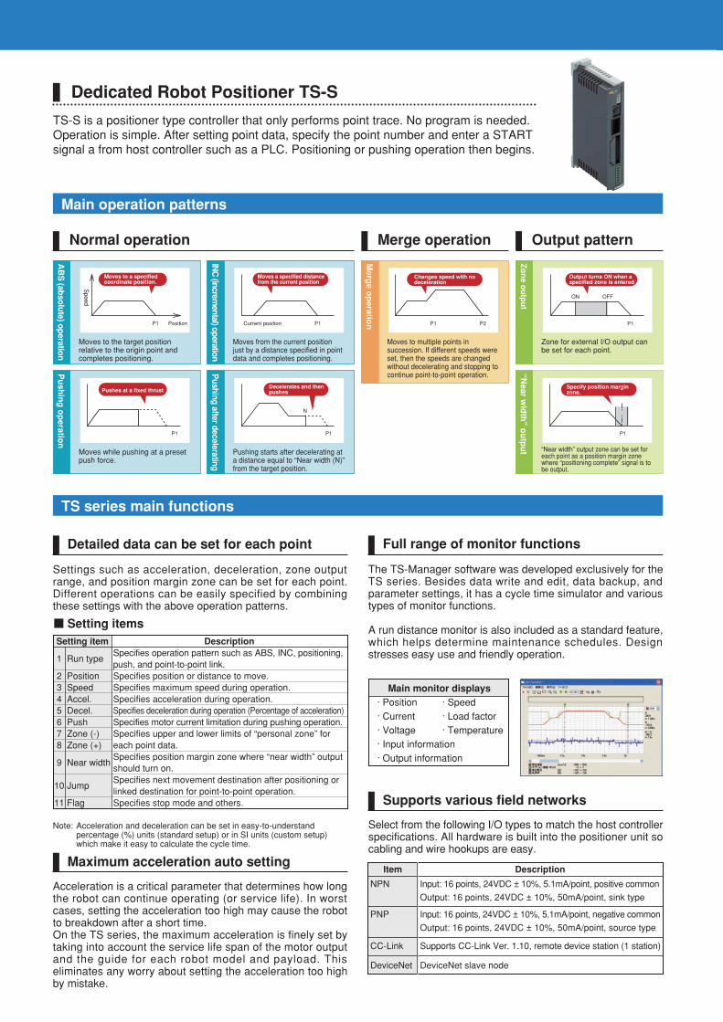
Main operation patterns
TS series main functions
AB
S (ab
solu
te) op
eration
Moves to the target position relative to the origin point and completes positioning.
INC
(incremental) operation
Moves from the current position just by a distance specified in point data and completes positioning.
Merg
e op
eration
Moves to multiple points in succession. If different speeds were set, then the speeds are changed without decelerating and stopping to continue point-to-point operation.
Zo
ne o
utp
ut
Zone for external I/O output can be set for each point.
P1
Output turns ON when a specified zone is entered
ON OFF
Pu
shin
g o
peratio
n
Moves while pushing at a preset push force.
Pushing after decelerating
Pushing starts after decelerating at a distance equal to “Near width (N)” from the target position.
“Near w
idth
” ou
tpu
t “Near width” output zone can be set for each point as a position margin zone where “positioning complete” signal is to be output.
P1 Position
Moves to a specified coordinate position.
P1Current position
Moves a specified distance from the current position
P1
Pushes at a fixed thrust
P1
Decelerates and then pushes
N
P1 P2
Changes speed with no deceleration
P1
Specify position margin zone.
Normal operation Merge operation Output pattern
Dedicated Robot Positioner TS-S
TS-S is a positioner type controller that only performs point trace. No program is needed.Operation is simple. After setting point data, specify the point number and enter a START signal a from host controller such as a PLC. Positioning or pushing operation then begins.
Full range of monitor functions
The TS-Manager software was developed exclusively for the TS series. Besides data write and edit, data backup, and parameter settings, it has a cycle time simulator and various types of monitor functions.
A run distance monitor is also included as a standard feature, which helps determine maintenance schedules. Design stresses easy use and friendly operation.
Supports various field networks
Select from the following I/O types to match the host controller specifications. All hardware is built into the positioner unit so cabling and wire hookups are easy.
NPN Input: 16 points, 24VDC ± 10%, 5.1mA/point, positive common
Output: 16 points, 24VDC ± 10%, 50mA/point, sink type
PNP Input: 16 points, 24VDC ± 10%, 5.1mA/point, negative common
Output: 16 points, 24VDC ± 10%, 50mA/point, source type
CC-Link Supports CC-Link Ver. 1.10, remote device station (1 station)
DeviceNet DeviceNet slave node
Main monitor displays· Position · Speed· Current · Load factor· Voltage · Temperature· Input information· Output information
Speed
Detailed data can be set for each point
Settings such as acceleration, deceleration, zone output range, and position margin zone can be set for each point. Different operations can be easily specified by combining these settings with the above operation patterns.
Setting items
Note: Acceleration and deceleration can be set in easy-to-understand percentage (%) units (standard setup) or in SI units (custom setup) which make it easy to calculate the cycle time.
Maximum acceleration auto setting
Acceleration is a critical parameter that determines how long the robot can continue operating (or service life). In worst cases, setting the acceleration too high may cause the robot to breakdown after a short time.On the TS series, the maximum acceleration is finely set by taking into account the service life span of the motor output and the guide for each robot model and payload. This eliminates any worry about setting the acceleration too high by mistake.
Item Description
Setting item Description
1
2345678
9
10
11
Run type
PositionSpeedAccel.Decel.PushZone (-)Zone (+)
Near width
Jump
Flag
Specifies operation pattern such as ABS, INC, positioning, push, and point-to-point link.Specifies position or distance to move.Specifies maximum speed during operation.Specifies acceleration during operation.Specifies deceleration during operation (Percentage of acceleration)Specifies motor current limitation during pushing operation.Specifies upper and lower limits of “personal zone” for each point data.Specifies position margin zone where “near width” output should turn on.Specifies next movement destination after positioning or linked destination for point-to-point operation.Specifies stop mode and others.
Output signal
Connection to Peripheral Units
Input signal
Signal name Meaning Description Meaning Description
PIN0 to PIN7
JOG+
JOG-
MANUAL
ORG
/LOCK
START
TEACH
RESET
SERVO
POUT0 to POUT7
OUT0
OUT1
OUT2
OUT3
ZONE
PZONE
MANU-S
ORG-S
TLM-S
/WARN
NEAR
MOVE
BUSY
END
/ALM
SRV-S
• Point number used to perform positioning operation• Alarm number when alarm has occurred
Allocate the following outputs to OUT0 to OUT3.
• Zone output • Personal zone output
• Manual mode status • Return-to-origin status
• Near width output • Movement-in-progress output
• Push status • Warning output
Turns ON while at the zone specified by parameter.
Turns ON while at the zone specified by point setting.
Turns ON when in manual mode.
Turns ON when return-to-origin is complete.
Turns ON during push in pushing operation.
Turns ON when warning is issued.
Turns ON when near width (position margin zone) is entered.
Turns on during movement.
Outputs ON during operation.
Outputs operation result. Turns ON when operation has ended normally.
Turns ON when operation is normal. Turns OFF when alarm has occurred.
Outputs ON at servo-on.
Point number selection
Control output 0
Control output 1
Control output 2
Control output 3
Zone output
Personal zone output
Manual mode status
Return-to-origin status
Push status
Warning output
Near width output
Movement in progress
Operation in progress
Operation complete
Alarm
Servo status
Point number selection
Jog (+)
Jog (-)
Manual mode
Return-to-origin
Interlock
Start
Teach
Reset
Servo ON
• Point number used to perform positioning operation• Point number to teach current position
Jogs in plus (+) direction when ON.
Jogs in plus (-) direction when ON.
ON: manual mode
Starts return-to-origin.
ON: Movement possible, OFF: Movement impossible
Starts moving to position specified by point number.
Teaches current position to specified point number.
• Resets alarm.• Resets point number output.• Clears remaining distance in relative positioning operation.
ON: Servo ON, OFF: Servo OFF
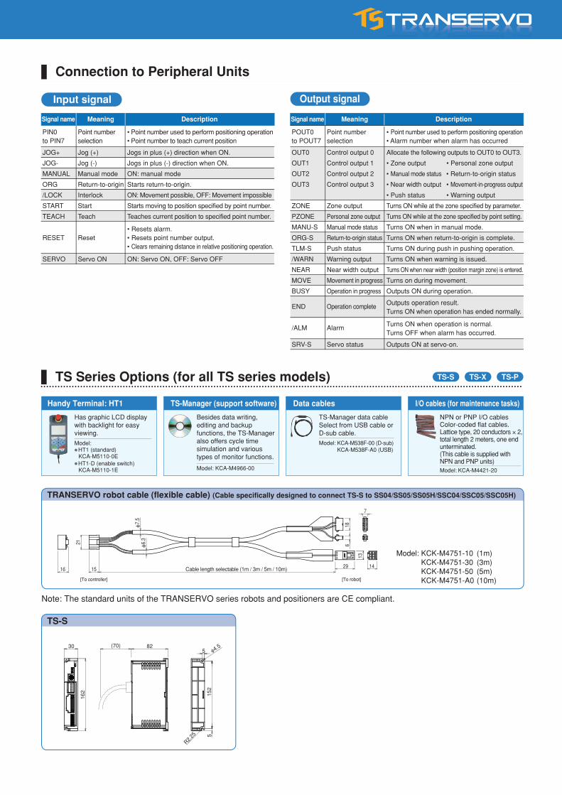
Note: The standard units of the TRANSERVO series robots and positioners are CE compliant.
TS Series Options (for all TS series models) TS-PTS-XTS-S
TRANSERVO robot cable (flexible cable) (Cable specifically designed to connect TS-S to SS04/SS05/SS05H/SSC04/SSC05/SSC05H)
Model: KCK-M4751-10 (1m) KCK-M4751-30 (3m) KCK-M4751-50 (5m) KCK-M4751-A0 (10m)[To controller] [To robot]
Cable length selectable (1m / 3m / 5m / 10m)
7
6
ϕ7.
5ϕ
6.3
18
29
13
1415
21
16
Handy Terminal: HT1 TS-Manager (support software) Data cables I/O cables (for maintenance tasks)
Has graphic LCD display with backlight for easy viewing.
Besides data writing, editing and backup functions, the TS-Manager also offers cycle time simulation and various types of monitor functions.
TS-Manager data cableSelect from USB cable or D-sub cable.
NPN or PNP I/O cablesColor-coded flat cables. Lattice type, 20 conductors × 2, total length 2 meters, one end unterminated. (This cable is supplied with NPN and PNP units)
Model:HT1 (standard)
KCA-M5110-0EHT1-D (enable switch)
KCA-M5110-1E Model: KCA-M4966-00
Model: KCA-M538F-00 (D-sub) KCA-M538F-A0 (USB)
Model: KCA-M4421-20
TS-S
30 82(70)
152
162
5
5
R2.25
ϕ4.5
Signal name
Main operation patterns
TS series main functions
AB
S (ab
solu
te) op
eration
Moves to the target position relative to the origin point and completes positioning.
INC
(incremental) operation
Moves from the current position just by a distance specified in point data and completes positioning.
Merg
e op
eration
Moves to multiple points in succession. If different speeds were set, then the speeds are changed without decelerating and stopping to continue point-to-point operation.
Zo
ne o
utp
ut
Zone for external I/O output can be set for each point.
P1
Output turns ON when a specified zone is entered
ON OFF
Pu
shin
g o
peratio
n
Moves while pushing at a preset push force.
Pushing after decelerating
Pushing starts after decelerating at a distance equal to “Near width (N)” from the target position.
“Near w
idth
” ou
tpu
t “Near width” output zone can be set for each point as a position margin zone where “positioning complete” signal is to be output.
P1 Position
Moves to a specified coordinate position.
P1Current position
Moves a specified distance from the current position
P1
Pushes at a fixed thrust
P1
Decelerates and then pushes
N
P1 P2
Changes speed with no deceleration
P1
Specify position margin zone.
Normal operation Merge operation Output pattern
Dedicated Robot Positioner TS-S
TS-S is a positioner type controller that only performs point trace. No program is needed.Operation is simple. After setting point data, specify the point number and enter a START signal a from host controller such as a PLC. Positioning or pushing operation then begins.
Full range of monitor functions
The TS-Manager software was developed exclusively for the TS series. Besides data write and edit, data backup, and parameter settings, it has a cycle time simulator and various types of monitor functions.
A run distance monitor is also included as a standard feature, which helps determine maintenance schedules. Design stresses easy use and friendly operation.
Supports various field networks
Select from the following I/O types to match the host controller specifications. All hardware is built into the positioner unit so cabling and wire hookups are easy.
NPN Input: 16 points, 24VDC ± 10%, 5.1mA/point, positive common
Output: 16 points, 24VDC ± 10%, 50mA/point, sink type
PNP Input: 16 points, 24VDC ± 10%, 5.1mA/point, negative common
Output: 16 points, 24VDC ± 10%, 50mA/point, source type
CC-Link Supports CC-Link Ver. 1.10, remote device station (1 station)
DeviceNet DeviceNet slave node
Main monitor displays· Position · Speed· Current · Load factor· Voltage · Temperature· Input information· Output information
Speed
Detailed data can be set for each point
Settings such as acceleration, deceleration, zone output range, and position margin zone can be set for each point. Different operations can be easily specified by combining these settings with the above operation patterns.
Setting items
Note: Acceleration and deceleration can be set in easy-to-understand percentage (%) units (standard setup) or in SI units (custom setup) which make it easy to calculate the cycle time.
Maximum acceleration auto setting
Acceleration is a critical parameter that determines how long the robot can continue operating (or service life). In worst cases, setting the acceleration too high may cause the robot to breakdown after a short time.On the TS series, the maximum acceleration is finely set by taking into account the service life span of the motor output and the guide for each robot model and payload. This eliminates any worry about setting the acceleration too high by mistake.
Item Description
Setting item Description
1
2345678
9
10
11
Run type
PositionSpeedAccel.Decel.PushZone (-)Zone (+)
Near width
Jump
Flag
Specifies operation pattern such as ABS, INC, positioning, push, and point-to-point link.Specifies position or distance to move.Specifies maximum speed during operation.Specifies acceleration during operation.Specifies deceleration during operation (Percentage of acceleration)Specifies motor current limitation during pushing operation.Specifies upper and lower limits of “personal zone” for each point data.Specifies position margin zone where “near width” output should turn on.Specifies next movement destination after positioning or linked destination for point-to-point operation.Specifies stop mode and others.
Output signal
Connection to Peripheral Units
Input signal
Signal name Meaning Description Meaning Description
PIN0 to PIN7
JOG+
JOG-
MANUAL
ORG
/LOCK
START
TEACH
RESET
SERVO
POUT0 to POUT7
OUT0
OUT1
OUT2
OUT3
ZONE
PZONE
MANU-S
ORG-S
TLM-S
/WARN
NEAR
MOVE
BUSY
END
/ALM
SRV-S
• Point number used to perform positioning operation• Alarm number when alarm has occurred
Allocate the following outputs to OUT0 to OUT3.
• Zone output • Personal zone output
• Manual mode status • Return-to-origin status
• Near width output • Movement-in-progress output
• Push status • Warning output
Turns ON while at the zone specified by parameter.
Turns ON while at the zone specified by point setting.
Turns ON when in manual mode.
Turns ON when return-to-origin is complete.
Turns ON during push in pushing operation.
Turns ON when warning is issued.
Turns ON when near width (position margin zone) is entered.
Turns on during movement.
Outputs ON during operation.
Outputs operation result. Turns ON when operation has ended normally.
Turns ON when operation is normal. Turns OFF when alarm has occurred.
Outputs ON at servo-on.
Point number selection
Control output 0
Control output 1
Control output 2
Control output 3
Zone output
Personal zone output
Manual mode status
Return-to-origin status
Push status
Warning output
Near width output
Movement in progress
Operation in progress
Operation complete
Alarm
Servo status
Point number selection
Jog (+)
Jog (-)
Manual mode
Return-to-origin
Interlock
Start
Teach
Reset
Servo ON
• Point number used to perform positioning operation• Point number to teach current position
Jogs in plus (+) direction when ON.
Jogs in plus (-) direction when ON.
ON: manual mode
Starts return-to-origin.
ON: Movement possible, OFF: Movement impossible
Starts moving to position specified by point number.
Teaches current position to specified point number.
• Resets alarm.• Resets point number output.• Clears remaining distance in relative positioning operation.
ON: Servo ON, OFF: Servo OFF
Note: The standard units of the TRANSERVO series robots and positioners are CE compliant.
TS Series Options (for all TS series models) TS-PTS-XTS-S
TRANSERVO robot cable (flexible cable) (Cable specifically designed to connect TS-S to SS04/SS05/SS05H/SSC04/SSC05/SSC05H)
Model: KCK-M4751-10 (1m) KCK-M4751-30 (3m) KCK-M4751-50 (5m) KCK-M4751-A0 (10m)[To controller] [To robot]
Cable length selectable (1m / 3m / 5m / 10m)
7
6
ϕ7.
5ϕ
6.3
18
29
13
1415
21
16
Handy Terminal: HT1 TS-Manager (support software) Data cables I/O cables (for maintenance tasks)
Has graphic LCD display with backlight for easy viewing.
Besides data writing, editing and backup functions, the TS-Manager also offers cycle time simulation and various types of monitor functions.
TS-Manager data cableSelect from USB cable or D-sub cable.
NPN or PNP I/O cablesColor-coded flat cables. Lattice type, 20 conductors × 2, total length 2 meters, one end unterminated. (This cable is supplied with NPN and PNP units)
Model:HT1 (standard)
KCA-M5110-0EHT1-D (enable switch)
KCA-M5110-1E Model: KCA-M4966-00
Model: KCA-M538F-00 (D-sub) KCA-M538F-A0 (USB)
Model: KCA-M4421-20
TS-S
30 82(70)
152
162
5
5
R2.25
ϕ4.5
Signal name
Ordering Method
Basic specifications Allowable overhang* Static loading moment
Controller
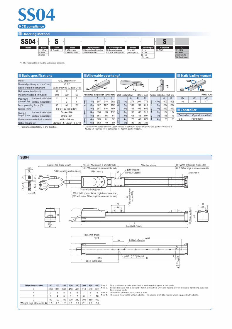
SS04SS04 – – S – – – – – – S –
Robot – Lead – Type – Brake – Origin position – Grease option – Stroke – Cable length*1 – Controller – I/O12 : 12mm S: Straight B: With brake N: Standard origin position N: Standard grease 50 to 400
(50mm pitch)1L : 1m S : TS-S NP : NPN
6 : 6mm N: With no brake Z: Non-motor side C: Clean room grease 3L : 3m PN : PNP2 : 2mm 5L : 5m CC : CC-Link
10L : 10m DN : DeviceNet
*1: The robot cable is flexible and resists bending.
Motor 42 Step motor
Repeated positioning accuracy*1 (mm) ±0.02
Deceleration mechanism Ball screw ϕ8 (Class C10)
Ball screw lead (mm) 12 6 2
Maximum speed (mm/sec) 600 300 100
Maximum payload (kg)
Horizontal installation 2 4 6
Vertical installation 1 2 4
Max. pressing force (N) 45 90 150
Stroke (mm) 50 to 400 (50 pitch)
Overalllength (mm)
Horizontal installation Stroke+216
Vertical installation Stroke+261
Maximum outside dimension of body cross-section W49×H59mm
Cable length (m) Standard : 1 / Option : 3, 5, 10
*1: Positioning repeatability in one direction.
M PM R
M Y
(Unit: N.m)
MY MP MR
16 19 17
Controller Operation method
TS-S Point trace
SS04
12.5
40.5
30.5
2415
13
20.5
8
161±2 : When origin is on motor side(161 : When origin is on non-motor side)
Effective stroke (55 : When origin is on motor side)55±2 : When origin is on non-motor side
21129±1 (Note 1)
206±2 (with brake) : When origin is on motor side(206 with brake : When origin is on non-motor side)
174±1 (with brake) (Note 1)
2-ϕ3H7 Depth 64-M4x0.7 Depth 8
33(T
oler
ance
bet
wee
nkn
ocks
±0.0
2 )
23±1 (Note 1)
Approx. 200 (Cable length)
Cable securing position (Note 2)
51 (S
lider
top
face
)
45
412532
58
LL+45 (with brake)
Ax50137.5B-M5x0.8 Depth8
182.5 (with brake)
50
162.5 C2
4
D
epth
6+0
.02
0
ϕ4H7 ( ) Depth6+0.012 0
207.5 (with brake)
R
1549
59
Effective stroke 50 100 150 200 250 300 350 400 Note 1. Stop positions are determined by the mechanical stoppers at both ends.Note 2. Secure the cable with a tie-band 100mm or less from unit’s end face to prevent the cable from being subjected
to excessive loads.Note 3. The cable’s minimum bend radius is R30.Note 4. These are the weights without a brake. The weights are 0.2kg heavier when equipped with a brake.
L 266 316 366 416 466 516 566 616
A 2 3 4 5 6 7 8 9
B 3 4 5 6 7 8 9 10
C 50 100 150 200 250 300 350 400
Weight (kg) (See note 4) 1.5 1.6 1.7 1.8 2.0 2.1 2.2 2.3
A
CB C
BA
AC
Horizontal installation (Unit: mm) Wall installation (Unit: mm) Vertical installation (Unit: mm)
A B C A B C A C
Lead
12
1kg 807 218 292
Lead
12
1kg 274 204 776
Lead
12
0.5kg 407 408
2kg 667 107 152 2kg 133 93 611 1kg 204 204
Lead
6
2kg 687 116 169 Lead
6
2kg 149 102 656
Lead
6
1kg 223 223
3kg 556 76 112 3kg 92 62 516 2kg 107 107
4kg 567 56 84 4kg 63 43 507
Lead
2
2kg 118 118
Lead
2
4kg 869 61 92
Lead
2
4kg 72 48 829 4kg 53 53
6kg 863 40 60 6kg 39 29 789
* Distance from center of slider upper surface to conveyor center-of-gravity at a guide service life of 10,000 km (Service life is calculated for 400mm stroke models).
CE compliance

Allowable overhang* Static loading moment
Controller
Basic specifications
Ordering Method
SS05SS05 – – S – – – – – – S –
Robot – Lead – Type – Brake – Origin position – Grease option – Stroke – Cable length*1 – Controller – I/O20 : 20mm S: Straight B: With brake N: Standard origin position N: Standard grease 50 to 800
(50mm pitch)1L : 1m S : TS-S NP : NPN
12 : 12mm N: With no brake Z: Non-motor side C: Clean room grease 3L : 3m PN : PNP6 : 6mm 5L : 5m CC : CC-Link
10L : 10m DN : DeviceNet
*1: Brake-equipped models can be selected only when the lead is 12mm or 6mm.
*2: The robot cable is flexible and resists bending.
Motor 42 Step motor
Repeated positioning accuracy*1 (mm) ±0.02
Deceleration mechanism Ball screw ϕ12 (Class C10)
Ball screw lead (mm) 20 12 6
Maximum speed (mm/sec)*2 1000 600 300
Maximum payload (kg)
Horizontal installation 4 6 10
Vertical installation – 1 2
Max. pressing force (N) 27 45 90
Stroke (mm) 50 to 800 (50 pitch)
Overalllength (mm)
Horizontal installation Stroke+230
Vertical installation Stroke+275
Maximum outside dimension of body cross-section W55×H56mm
Cable length (m) Standard : 1 / Option : 3, 5, 10
*1: Positioning repeatability in one direction.*2: When the stroke is longer than 650mm, the ball screw may
resonate depending on the moving range (critical speed). In that case, reduce the speed by referring to the maximum speeds shown in the table under the dimensional drawing.
M PM R
M Y
(Unit: N.m)
MY MP MR
25 33 30
Controller Operation method
TS-S Point trace
SS05
Effective stroke 50 100 150 200 250 300 350 400 450 500 550 600 650 700 750 800
L 280 330 380 430 480 530 580 630 680 730 780 830 880 930 980 1030
A 3 4 5 6 7 8 9 10 11 12 13 14 15 16 17 18
B 4 5 6 7 8 9 10 11 12 13 14 15 16 17 18 19
C 100 150 200 250 300 350 400 450 500 500 500 500 500 500 500 500
Weight (kg) (See note 4) 2.1 2.3 2.5 2.7 2.8 3.0 3.2 3.4 3.6 3.8 4.0 4.2 4.4 4.6 4.8 5.0
Maximum speed for each stroke (mm / sec) (Note 5)
Lead 20 1000 933 833 733 633
Lead 12 600 560 500 440 380
Lead 6 300 280 250 220 190
Speed setting – 93% 83% 73% 63%
Note 1. Stop positions are determined by the mechanical stoppers at both ends.
Note 2. Secure the cable with a tie-band 100mm or less from unit’s end face to prevent the cable from being subjected to excessive loads.
Note 3. The cable’s minimum bend radius is R30.Note 4. These are the weights without a brake. The
weights are 0.2kg heavier when equipped with a brake.
Note 5. When the stroke is longer than 650mm, the ball screw may resonate depending on the moving range (critical speed). In that case, adjust to reduce the speed on the program by referring to the maximum speeds shown in the table at the left.
24
30.5
40.5
12.5
13
1520
.58
Approx. 200 (Cable length) 178±2: When origin is on motor side(178 : When origin is on non-motor side)
140±1 (Note 1)Cable securing position (Note 2)
218±2 (with brake) : When origin is on motor side(218 with brake : When origin is on non-motor side)
180±1 (with brake) (Note 1)
34
Effective stroke
2-ϕ4H7 Depth 64-M4x0.7 Depth8
42(T
oler
ance
bet
wee
nkn
ocks
±0.0
2 )
(55 : When origin is on motor side)52±2 : When origin is on non-motor side
14±1(Note 1)
5034
57
(Slid
er to
p fa
ce)
51
4270
LL+40 (with brake)
2455
56
50Ax50101.5
141.5 (with brake)
B-M6x1 Depth8
126.5 Cϕ4H7 ( ) Depth6+0.012
0
166.5 (with brake)
2
R
4
D
epth
6+0
.02
0
A
CB C
BA
AC
Horizontal installation (Unit: mm) Wall installation (Unit: mm) Vertical installation (Unit: mm)
A B C A B C A C
Lead
20
2kg 413 139 218
Lead
20
2kg 192 123 372
Lead
12
0.5kg 578 579
4kg 334 67 120 4kg 92 51 265 1kg 286 286
Lead
12
4kg 347 72 139L
ead12
4kg 109 57 300
Lead
6
1kg 312 312
6kg 335 47 95 6kg 63 31 263 2kg 148 148
Lead
6
4kg 503 78 165 Lead
6
4kg 134 63 496
8kg 332 37 79 6kg 76 35 377
10kg 344 29 62 8kg 47 22 355
* Distance from center of slider upper surface to conveyor center-of-gravity at a guide service life of 10,000 km (Service life is calculated for 600mm stroke models).
High lead: Lead 20 CE compliance

Ordering Method
Basic specifications Allowable overhang* Static loading moment
Controller
SS05HSS05H – – S – – – – – – S –
Robot – Lead – Type – Brake – Origin position – Grease option – Stroke – Cable length*1 – Controller – I/O20 : 20mm S: Straight B: With brake N: Standard origin position N: Standard grease 50 to 800
(50mm pitch)1L : 1m S : TS-S NP : NPN
12 : 12mm N: With no brake Z: Bon-motor side C: Clean room grease 3L : 3m PN : PNP6 : 6mm 5L : 5m CC : CC-Link
10L : 10m DN : DeviceNet
*1: Brake-equipped models can be selected only when the lead is 12mm or 6mm. *2: The robot cable is flexible and resists bending.
Motor 42 Step motor
Repeated positioning accuracy*1 (mm) ±0.02
Deceleration mechanism Ball screw ϕ12 (Class C10)
Ball screw lead (mm) 20 12 6
Maximum speed (mm/sec)
Horizontal installation 1000 600 300
Vertical installation – 500 250
Maximum payload (kg)
Horizontal installation 6 8 12
Vertical installation – 2 4
Max. pressing force (N) 36 60 120
Stroke (mm) 50 to 800 (50 pitch)
Overall length (mm)
Horizontal installation Stroke+286
Vertical installation Stroke+331
Maximum outside dimension of body cross-section W55×H56mm
Cable length (m) Standard : 1 / Option : 3, 5, 10
*1: Positioning repeatability in one direction.*2: When the stroke is longer than 650mm, the ball screw may
resonate depending on the moving range (critical speed). In that case, reduce the speed by referring to the maximum speeds shown in the table under the dimensional drawing.
A
CB C
BA
AC
Horizontal installation (Unit: mm) Wall installation (Unit: mm) Vertical installation (Unit: mm)
A B C A B C A C
Lead
20
2kg 599 225 291 Lead
20
2kg 262 203 554
Lead
12
1kg 458 459
4kg 366 109 148 4kg 118 88 309 2kg 224 224
6kg 352 71 104 6kg 71 49 262
Lead
6
2kg 244 245
Lead
12
4kg 500 118 179 Lead
124kg 146 96 449 4kg 113 113
6kg 399 79 118 6kg 85 55 334
8kg 403 56 88 8kg 55 34 305
Lead
6
6kg 573 83 136
Lead
6
6kg 101 62 519
8kg 480 61 100 8kg 64 39 413
10kg 442 47 78 10kg 43 26 355
12kg 465 39 64 12kg 28 17 338
* Distance from center of slider upper surface to conveyor center-of-gravity at a guide service life of 10,000 km (Service life is calculated for 600mm stroke models).
M PM R
M Y
(Unit: N.m)
MY MP MR
32 38 34
Controller Operation method
TS-S Point trace
SS05H
12.5
40.5
30.5
24
13
1520
.58
Approx. 200 (Cable length) 223.5±2 : When origin is on motor side(223.5 : When origin is on non-motor side)
Effective stroke (62.5 : When origin is on motor side)
62.5±2: When origin is on non-motor side175.5±1 (Note 1) 14.5±1 (Note 1)
Cable securing position (Note 2) 432-ϕ4H7 Depth6
4-M5x0.8 Depth10
243.5±2 (with brake) : When origin is on motor side(243.5 with brake : When origin is on non-motor side)
195.5±1(with brake) (Note 1)
43(T
oler
ance
bet
wee
nkn
ocks
±0.0
2 )
2455
56
LL+20 (with brake)
34
51
52
60
(Slid
er to
p fa
ce)
5390
50Ax50141.5
161.5 (with brake)
B-M6x1 Depth8
166.5 C2
186.5 (with brake)
R4
Dep
th6
+0.0
20
ϕ4H7 ( ) Depth6+0.012 0
Effective stroke 50 100 150 200 250 300 350 400 450 500 550 600 650 700 750 800
L 336 386 436 486 536 586 636 686 736 786 836 886 936 986 1036 1086
A 3 4 5 6 7 8 9 10 11 12 13 14 15 16 17 18
B 4 5 6 7 8 9 10 11 12 13 14 15 16 17 18 19
C 100 150 200 250 300 350 400 450 500 500 500 500 500 500 500 500
Weight (kg) (See note 4) 2.4 2.6 2.8 3.0 3.2 3.4 3.6 3.8 4.0 4.2 4.4 4.5 4.7 4.9 5.1 5.3
Maximum speed for each stroke (mm / sec) (Note 5)
Lead 20 1000 933 833 733 633
Lead 12 (Horizontal) 600 560 500 440 380
Lead 12 (Vertical) 500 440 380
Lead 6 (Horizontal) 300 280 250 220 190
Lead 6 (Vertical) 250 220 190
Note 1. Stop positions are determined by the mechanical stoppers at both ends.
Note 2. Secure the cable with a tie-band 100mm or less from unit’s end face to prevent the cable from being subjected to excessive loads.
Note 3. The cable’s minimum bend radius is R30.Note 4. These are the weights without a brake.
The weights are 0.2kg heavier when equipped with a brake.
Note 5. When the stroke is longer than 650mm, the ball screw may resonate depending on the moving range (critical speed). In that case, adjust to reduce the speed on the program by referring to the maximum speeds shown in the table at the left.
High lead: Lead 20 CE compliance
SSC04
Static loading moment
Controller
Allowable overhang* Basic specifications
Ordering Method
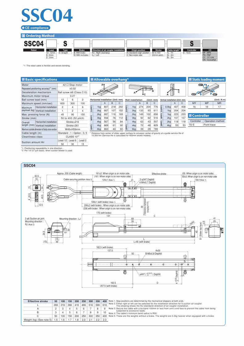
SSC04 – – S – – – – – – S –
Robot – Lead – Type – Brake – Direction of air coupler installation – Origin position – Stroke – Cable length*1 – Controller – I/O12 : 12mm S: Straight B: With brake RJ : Right (standarg) N: Standard origin position 50 to 400
(50mm pitch)1L : 1m S : TS-S NP : NPN
6 : 6mm N: With no brake LJ : Left Z: Non-motor side 3L : 3m PN : PNP2 : 2mm 5L : 5m CC : CC-Link
DN : DeviceNet
*1: The robot cable is flexible and resists bending.
Controller Operation method
TS-S Point trace
Motor 42 Step motor
Repeated positioning accuracy*1 (mm) ±0.02
Deceleration mechanism Ball screw ϕ8 (Class C10)
Maximum motor torque 0.27
Ball screw lead (mm) 12 6 2
Maximum speed (mm/sec) 600 300 100
Maximum payload (kg)
Horizontal installation 2 4 6
Vertical installation 1 2 4
Max. pressing force (N) 45 90 150
Stroke (mm) 50 to 400 (50 pitch)
Overalllength (mm)
Horizontal installation Stroke+216
Vertical installation Stroke+261
Maximum outside dimension of body cross-section W49×H59mm
Cable length (m) Standard : 1 / Option : 3, 5
Cleanliness class CLASS 10*2
Suction amount AirLead 12 Lead 6 Lead 2
50 30 15
*1: Positioning repeatability in one direction. *2: Per 1cf (0.1μm base), when suction blower is used.
M PM R
M Y
(Unit: N.m)
MY MP MR
16 19 17
A
CB C
BA
AC
Horizontal installation (Unit: mm) Wall installation (Unit: mm) Vertical installation (Unit: mm)
A B C A B C A C
Lead
12
1kg 807 218 292
Lead
12
1kg 274 204 776
Lead
12
0.5kg 407 408
2kg 667 107 152 2kg 133 93 611 1kg 204 204
Lead
6
2kg 687 116 169 Lead
6
2kg 149 102 656
Lead
6
1kg 223 223
3kg 556 76 112 3kg 92 62 516 2kg 107 107
4kg 567 56 84 4kg 63 43 507
Lead
2
2kg 118 118
Lead
2
4kg 869 61 92
Lead
2
4kg 72 48 829 4kg 53 53
6kg 863 40 60 6kg 39 29 789
* Distance from center of slider upper surface to conveyor center-of-gravity at a guide service life of 10,000 km (Service life is calculated for 400mm stroke models).
CE compliance
SSC04
40.5
12.5
30.5
2415
13
20.5
8
161±2: When origin is on motor side(161: When origin is on non-motor side)
Effective stroke (55: When origin is on motor side)55±2: When origin is on non-motor side
21124±1 (Note 1) 2-ϕ3H7 Depth64-M4x0.7 Depth8
18±1(Note 1)
Approx. 200 (Cable length)
Cable securing position (Note 3)
206±2 (with brake) : When origin is on motor side(206 with brake : When origin is on non-motor side)
169±1 (with brake) (Note 1)
33(T
oler
ance
bet
ween
knoc
ks±0
.02 )
1549
59
(15)
2-ϕ6 Suction air jointMounting direction : RJ (Note 2)
Mounting direction : LJ
34.5
51 (S
lider
top
face
)
4125
45
0.5
6835
131 C176 (with brake)
(ϕ34)
LL+45 (with brake)
Ax50137.5B-M5x0.8 Depth8
182.5 (with brake)
50
D
2
162.5207.5 (with brake)
ϕ4H7 ( ) Depth6+0.012 0
4
Dep
th6
+0.0
20
R
Effective stroke 50 100 150 200 250 300 350 400 Note 1. Stop positions are determined by the mechanical stoppers at both ends.Note 2. Either right or left can be selected for the installation direction for 6 suction air coupler.
This drawing shows the RJ (standard) direction of air coupler installation.Note 3. Secure the cable with a tie-band 100mm or less from unit’s end face to prevent the cable from being
subjected to excessive loads.Note 4. The cable’s minimum bend radius is R30.Note 5. These are the weights without a brake. The weights are 0.2kg heavier when equipped with a brake.
L 266 316 366 416 466 516 566 616
A 2 3 4 5 6 7 8 9
B 3 4 5 6 7 8 9 10
C 50 100 150 200 250 300 350 400
Weight (kg) (See note 5) 1.5 1.6 1.7 1.8 2.0 2.1 2.2 2.3
SSC05
Static loading moment
Controller
Allowable overhang* Basic specifications
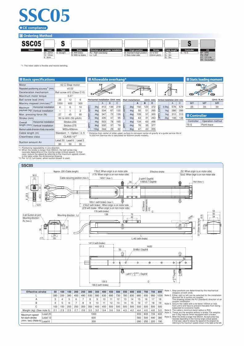
Ordering Method
Controller Operation method
TS-S Point trace
Motor 42 Step motor
Repeated positioning accuracy*1 (mm) ±0.02
Deceleration mechanism Ball screw ϕ12 (Class C10)
Maximum motor torque 0.27
Ball screw lead (mm) 20 12 6
Maximu mspeed (mm/sec)*2 1000 600 300
Maximum payload (kg)
Horizontal installation 4 6 10
Vertical installation – 1 2
Max. pressing force (N) 27 45 90
Stroke (mm) 50 to 800 (50 pitch)
Overalllength (mm)
Horizontal installation Stroke+230
Vertical installation Stroke+275
Maximum outside dimension of body cross-section W55×H56mm
Cable length (m) Standard : 1 / Option : 3, 5
Cleanliness class CLASS 10*3
Suction amount AirLead 20 Lead 6 Lead 2
80 50 30
*1: Positioning repeatability in one direction.*2: When the stroke is longer than 650mm, the ball screw may
resonate depending on the moving range (critical speed). In that case, reduce the speed by referring to the maximum speeds shown in the table under the dimensional drawing.
*3: Per 1cf (0.1μm base), when suction blower is used.
SSC05 – – S – – – – – – S –
Robot – Lead – Type – Brake – Direction of air coupler installation – Origin position – Stroke – Cable length*1 – Controller – I/O20 : 20mm S: Straight B: With brake RJ : Right (standarg) N: Standard origin position 50 to 800
(50mm pitch)1L : 1m S : TS-S NP : NPN
12 : 12mm N: With no brake LJ : Left Z: Non-motor side 3L : 3m PN : PNP6 : 6mm 5L : 5m CC : CC-Link
DN : DeviceNet
*1: The robot cable is flexible and resists bending.
M PM R
M Y
(Unit: N.m)
MY MP MR
25 33 30
A
CB C
BA
AC
Horizontal installation (Unit: mm) Wall installation (Unit: mm) Vertical installation (Unit: mm)
A B C A B C A C
Lead
20
2kg 413 139 218
Lead
20
2kg 192 123 372
Lead
12
0.5kg 578 579
4kg 334 67 120 4kg 92 51 265 1kg 286 286
Lead
12
4kg 347 72 139
Lead
12
4kg 109 57 300
Lead
6
1kg 312 312
6kg 335 47 95 6kg 63 31 263 2kg 148 148
Lead
6
4kg 503 78 165 Lead
64kg 134 63 496
8kg 332 37 79 6kg 76 35 377
10kg 344 29 62 8kg 47 22 355
* Distance from center of slider upper surface to conveyor center-of-gravity at a guide service life of 10,000 km (Service life is calculated for 600mm stroke models).
CE compliance
SSC05
42 (T
olera
nce
betw
een k
nock
s±0
.02)
Approx. 200 (Cable length)
34
178±2: When origin is on motor side(178: When origin is on non-motor side)
Effective stroke (52: When origin is on motor side)52±2: When origin is on non-motor side
2-ϕ4H7 Depth64-M4x0.7 Depth8
140±1 (Note 1)
14±1(Note 1)
218±2 (with brake) : When origin is on motor side(218 with brake : When origin is on non-motor side)
180±1 (with brake) (Note 1)
Cable securing position (Note 3)
24
30.5
40.5
12.5
13
1520
.58
2455
56
(17)
2-ϕ6 Suction air jointMounting direction : RJ (Note 2)
Mounting direction : LJ
36
4270
51
138C178 (with brake)
LL+40 (with brake)
(ϕ34)5034
57
(Slid
er to
p fa
ce)
53
(0.5
)
50Ax50101.5
141.5 (with brake)
B-M6x1 Depth8
126.5 D
2
166.5 (with brake)
R
ϕ4H7 ( ) Depth6+0.012 0
4
D
epth
6+0
.02
0
Effective stroke 50 100 150 200 250 300 350 400 450 500 550 600 650 700 750 800
L 280 330 380 430 480 530 580 630 680 730 780 830 880 930 980 1030
A 3 4 5 6 7 8 9 10 11 12 13 14 15 16 17 18
B 4 5 6 7 8 9 10 11 12 13 14 15 16 17 18 19
C 100 150 200 250 300 350 400 450 500 500 500 500 500 500 500 500
Weight (kg) (See note 5) 2.1 2.3 2.5 2.7 2.8 3.0 3.2 3.4 3.6 3.8 4.0 4.2 4.4 4.6 4.8 5.0
Maximum speed for each stroke (mm / sec) (Note 6)
Lead 20 1000 933 833 733 633
Lead 12 600 560 500 440 380
Lead 6 300 280 250 220 190
Note 1. Stop positions are determined by the mechanical stoppers at both ends.
Note 2. Either right or left can be selected for the installation direction for 6 suction air coupler. This drawing shows the RJ (standard) direction of air coupler installation.
Note 3. Secure the cable with a tie-band 100mm or less from unit’s end face to prevent thecable from being subjected to excessive loads.
Note 4. The cable’s minimum bend radius is R30.Note 5. These are the weights without a brake.The weights
are 0.2kg heavier when equipped with a brake.Note 6. When the stroke is longer than 650mm, the ball screw may
resonate depending on the moving range (critical speed). In that case, adjust to reduce the speed on the program by referring to the maximum speeds shown in the table at the left.
Static loading moment
Controller
Allowable overhang* Basic specifications
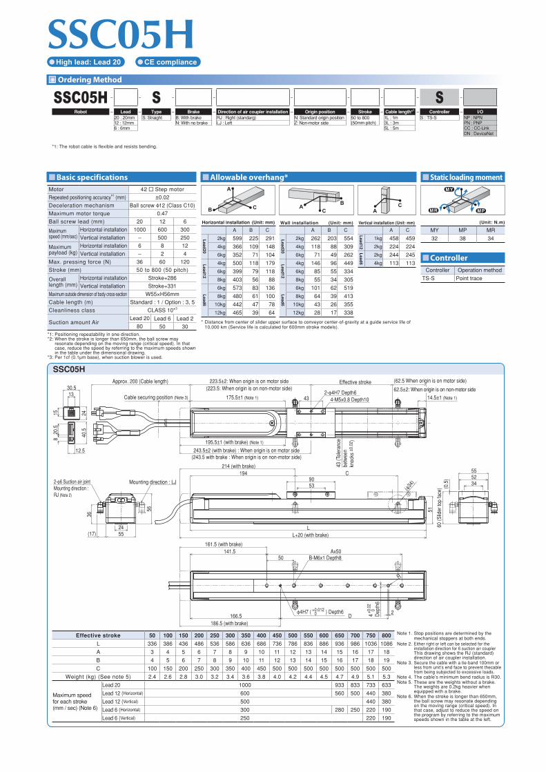
Ordering Method
SSC05H – – S – – – – – – S –
Robot – Lead – Type – Brake – Direction of air coupler installation – Origin position – Stroke – Cable length*1 – Controller – I/O20 : 20mm S: Straight B: With brake RJ : Right (standarg) N: Standard origin position 50 to 800
(50mm pitch)1L : 1m S : TS-S NP : NPN
12 : 12mm N: With no brake LJ : Left Z: Non-motor side 3L : 3m PN : PNP6 : 6mm 5L : 5m CC : CC-Link
DN : DeviceNet
*1: The robot cable is flexible and resists bending.
Controller Operation method
TS-S Point trace
Motor 42 Step motor
Repeated positioning accuracy*1 (mm) ±0.02
Deceleration mechanism Ball screw ϕ12 (Class C10)
Maximum motor torque 0.47
Ball screw lead (mm) 20 12 6
Maximum speed (mm/sec)
Horizontal installation 1000 600 300
Vertical installation – 500 250
Maximum payload (kg)
Horizontal installation 6 8 12
Vertical installation – 2 4
Max. pressing force (N) 36 60 120
Stroke (mm) 50 to 800 (50 pitch)
Overalllength (mm)
Horizontal installation Stroke+286
Vertical installation Stroke+331
Maximum outside dimension of body cross-section W55×H56mm
Cable length (m) Standard : 1 / Option : 3, 5
Cleanliness class CLASS 10*3
Suction amount AirLead 20 Lead 6 Lead 2
80 50 30*1: Positioning repeatability in one direction.*2: When the stroke is longer than 650mm, the ball screw may
resonate depending on the moving range (critical speed). In that case, reduce the speed by referring to the maximum speeds shown in the table under the dimensional drawing.
*3: Per 1cf (0.1μm base), when suction blower is used.
M PM R
M Y
(Unit: N.m)
MY MP MR
32 38 34
A
CB C
BA
AC
Horizontal installation (Unit: mm) Wall installation (Unit: mm) Vertical installation (Unit: mm)
A B C A B C A C
Lead
20
2kg 599 225 291 Lead
20
2kg 262 203 554
Lead
12
1kg 458 459
4kg 366 109 148 4kg 118 88 309 2kg 224 224
6kg 352 71 104 6kg 71 49 262
Lead
6
2kg 244 245
Lead
12
4kg 500 118 179 Lead
124kg 146 96 449 4kg 113 113
6kg 399 79 118 6kg 85 55 334
8kg 403 56 88 8kg 55 34 305
Lead
6
6kg 573 83 136
Lead
6
6kg 101 62 519
8kg 480 61 100 8kg 64 39 413
10kg 442 47 78 10kg 43 26 355
12kg 465 39 64 12kg 28 17 338
* Distance from center of slider upper surface to conveyor center-of-gravity at a guide service life of 10,000 km (Service life is calculated for 600mm stroke models).
SSC05H High lead: Lead 20 CE compliance
SSC05HApprox. 200 (Cable length)
Cable securing position (Note 3)
12.5
40.5
30.5
24
13
1520
.58
223.5±2: When origin is on motor side(223.5: When origin is on non-motor side)
Effective stroke
175.5±1 (Note 1) 432-ϕ4H7 Depth6
4-M5x0.8 Depth10
(62.5 When origin is on motor side)
62.5±2: When origin is on non-motor side
14.5±1 (Note 1)
43 (T
oler
ance
betw
een
knoc
ks ±
0.02
)
243.5±2 (with brake) : When origin is on motor side(243.5 with brake : When origin is on non-motor side)
195.5±1 (with brake) (Note 1)
2455
56
(17)
2-ϕ6 Suction air jointMounting direction : RJ (Note 2)
Mounting direction : LJ
36
5390
C214 (with brake)
194
(ϕ34
) 3452
60
(Slid
er to
p fa
ce) (0
.5)
55
LL+20 (with brake)
50Ax50141.5
161.5 (with brake)
B-M6x1 Depth8
166.5 D2
186.5 (with brake)
R
ϕ4H7 ( ) Depth6+0.012 0 4 D
epth
6
+0.0
20
51
Effective stroke 50 100 150 200 250 300 350 400 450 500 550 600 650 700 750 800
L 336 386 436 486 536 586 636 686 736 786 836 886 936 986 1036 1086
A 3 4 5 6 7 8 9 10 11 12 13 14 15 16 17 18
B 4 5 6 7 8 9 10 11 12 13 14 15 16 17 18 19
C 100 150 200 250 300 350 400 450 500 500 500 500 500 500 500 500
Weight (kg) (See note 5) 2.4 2.6 2.8 3.0 3.2 3.4 3.6 3.8 4.0 4.2 4.4 4.5 4.7 4.9 5.1 5.3
Maximum speed for each stroke (mm / sec) (Note 6)
Lead 20 1000 933 833 733 633
Lead 12 (Horizontal) 600 560 500 440 380
Lead 12 (Vertical) 500 440 380
Lead 6 (Horizontal) 300 280 250 220 190
Lead 6 (Vertical) 250 220 190
Note 1. Stop positions are determined by the mechanical stoppers at both ends.
Note 2. Either right or left can be selected for the installation direction for 6 suction air coupler This drawing shows the RJ (standard) direction of air coupler installation.
Note 3. Secure the cable with a tie-band 100mm or less from unit’s end face to prevent thecable from being subjected to excessive loads.
Note 4. The cable’s minimum bend radius is R30.Note 5. These are the weights without a brake.
The weights are 0.2kg heavier when equipped with a brake.
Note 6. When the stroke is longer than 650mm, the ball screw may resonate depending on the moving range (critical speed). In that case, adjust to reduce the speed on the program by referring to the maximum speeds shown in the table at the left.

201005-C
In concideration of environment, this catalogue is made of recycled paper.
Specifications and appearance are subject to change without prior notice.
IM Operations882 Soude, Naka-ku, Hamamatsu, Shizuoka 435-0054, JapanTel 81-53-460-6103 Fax 81-53-460-6811
URL http://www.yamaha-motor.co.jp/global/industrial/robot/E-mail [email protected]