the u2-hullz a simple, practical, 2 module wedge hull...
TRANSCRIPT
PortableBoatPlans.com
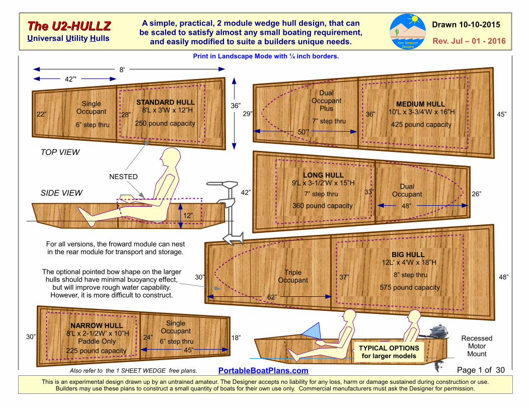
BIG HULL 12L' x 4'W x 18”H
575 pound capacity
TripleOccupant
Drawn 10-10-2015
Print in Landscape Mode with ¼ inch borders.
Page 1 of This is an experimental design drawn up by an untrained amateur. The Designer accepts no liability for any loss, harm or damage sustained during construction or use.
Builders may use these plans to construct a small quantity of boats for their own use only. Commercial manufacturers must ask the Designer for permission.
Ken SimpsonDesigns
30
The U2-HULLZThe U2-HULLZUniversal Utility Hulls
A simple, practical, 2 module wedge hull design, that can be scaled to satisfy almost any small boating requirement,
and easily modified to suite a builders unique needs.
LONG HULL 9'L x 3-1/2'W x 15”H
360 pound capacity
DualOccupant
36”
8'
DualOccupant
Plus
425 pound capacity
MEDIUM HULL 10'L x 3-3/4'W x 16”H
The optional pointed bow shape on the larger hulls should have minimal buoyancy effect,
but will improve rough water capability. However, it is more difficult to construct.
RecessedMotorMount
For all versions, the froward module can nest in the rear module for transport and storage.
NESTED
TYPICAL OPTIONSfor larger models
29” 45”36”
26”42” 33”
48”30” 37”
250 pound capacity
SingleOccupant
STANDARD HULL 8'L x 3'W x 12”H
22” 28”
42”'
50”'
48”
62”
NARROW HULL 8'L x 2-1/2W' x 10”H
Paddle Only225 pound capacity
SingleOccupant
30” 18”24”
45”
TOP VIEW
SIDE VIEW
Also refer to the 1 SHEET WEDGE free plans.
7” step thru6” step thru
7” step thru
8” step thru
6” step thru
Rev. Jul – 01 - 2016
12”

The idea for the U2-HullzU2-Hullz design is intended to provide a simple yet multi-useful, truly portable hull configuration.It includes an ample beam, great freeboard, generous volume, seating variety, and safety buoyancy.It is sturdy, easy to build, very portable and utilizes a standard trolling or small gas motor for power.
To have strength and yet be lightweight, the plans use some non-traditional methods of assembly , specifically the “Tape & Glue 2” construction process developed and incorporated by the designer.
This provides a durable, yet truly portable, finished boat, and the building process is easily mastered by the home handyman and amateur boat builder.
As a result, only hand tools, a jig-saw, a power drill and a large carpenters square, scissors, and tape measure are all that will be required throughout the assembly process.
Be selective in your choice of materials. Use plywood that is preferably exterior rated.Marine Plywood is very expensive, so the use of ACX Grade is recommended, but be choosy.
It is important to note, the final choice of materials is the decision of the builder.We have made specific recommendations, but if the builder has previous experience with different
methods and materials, that is their choice, and we respect that decision.Certainly, minor changes in design are encouraged, to provide a 'custom' boat to
satisfy a builders specific needs. We do not make changes to the drawings. This would be up to the individual builder, and their responsibility. Also, it is very
important that none of the basic design parameters be drastically modified, as this may adversely affect overall boat safety or performance.
Seating choice is also up to the builder. Bench type seating is suggested, but pedestal seats can be implemented.It should also be noted that the hull modules can be glued and screwed together,
for those that do not have limitations of storage or transportation.
The hull will be constructed using 1/4” plywood, for greater durability, or the exterior could also be fiberglassed , allowing yet thinner and lighter plywood hull building material .
Any questions or comments regarding the construction and/or design of this project will be responded to in a timely fashion.Note: These plans are hand drawn one line at a time, not CAD, and as such are prone to minor drawing flaws.
Thank you for your interest, and for purchasing these plans, and good luck with your project. And don’t forget to visit www.PortableBoatPlans.Com for new designs and updates.
Happy Boating ! Ken Simpson , Designer
PortableBoatPlans.com
General Notes
Page 2
The U2-HULLZThe U2-HULLZ
29” 45”36”
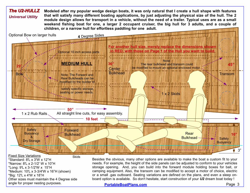
Modeled after my popular wedge design boats, it was only natural that I create a hull shape with features that will satisfy many different boating applications, by just adjusting the physical size of the hull. The 2 module design allows for transport in a vehicle, without the need of a trailer. Typical uses are as a small weekend fishing boat for one, a larger 2 occupant cruiser, the big hull for 3 adults, and a couple of children, or a narrow hull for effortless paddling for one adult.
Universal Utility
Bow TransomCenterBulkhead
MEDIUM HULL
Besides the obvious, many other options are available to make the boat a custom fit to your needs. For example, the height of the side panels can be adjusted to conform to your vehicles storage opening. And, you can build into the forward module holding boxes for bait, or camping equipment. Also, the transom can be modified to accept a motor of choice, electric or a small .gas outboard. Seating variations are defined on the plans, and even a sleep on-board option is available. So don't hesitate, start construction of your U2 dream boat today !
50”
16”
PortableBoatPlans.com Page 3
Optional Bow on larger hulls
SafetyBuoyancy
&Dry Storage
SafetyBuoyancy
3”
All straight line cuts, for easy assembly.
Optional 10 inch access ports
ForwardBulkhead
Note:The rear bulkhead and transom could
be modified to mount an optional enclosed motor.
Note: The Forward and Rear Bulkheads can be
modified by the builder to
satisfy specific storage, seating or power needs.
Skids
1 x 2 Rub Rails
8”
For another hull size, merely replace the dimensions shown in RED, with those on Page 1 of the Hull you want to build.
RearBulkhead
10 feet
1 x 2 Skids
4 Degree Sides
Fixed Size Variations*Standard: 8'L x 3'W x 12”H *Narrow: 8'L x 2-1/2' W x 10”H*Long: 9'L x 3-1/2'W x 15”H*Medium: 10'L x 3-3/4'W x 16”H (shown)*Big: 12'L x 4'W x 18”HOther sizes must maintain the 4 Degree side angle for proper nesting purposes.

The U2-HULLZThe U2-HULLZ
PortableBoatPlans.com Page 4
PRE-CONSTRUCTION NOTES
The previous three pages should have given you a good idea of the U2 Hullz concept, and what the different size options can provide.It is important to note that construction methods, and hull features, will change due to load and performance factors. For example, the smaller hulls will utilize ¼ inch plywood for all hull panels (sides, decks and bottom), while the larger hulls will need ½ inch, or thicker, for the base and bulkhead panels. In some instances the builder will be responsible for making this decision, based primarily on their intended use and capacity factors. So, the construction notes that follow are intended as recommended processes, which can, and should, be modified to suite the builders needs and prior boat building experience.
The Medium Hull design is being detailed, as it embodies the primary features of both the smaller and larger size hulls.
Remember, read and understand the building instructions thoroughly prior to starting construction.
Finally, there are 2 construction “Laws” to also remember when building a wooden boat..
While planning, marking and cutting the plywood: Measure twice, and cut once !and
When actual construction begins:
Murphy's Law: The Glue Dries Before The Mistake Is Found !
These “Laws” pretty much dictate that attention to detail is a must. Don't forget, people will rely on you for their safety!
IMPORTANTRemember, when laying out the panels on the plywood, pencil mark on the C side only. The good side A must be facing down. This is because you will want to cut the panels from the C side, to prevent splintering on the good side of the plywood, which always faces to the outside of the hull. And also remember, there is a port (left) side panel and a starboard (right) side panel. The plywood sheets are laid out to provide this orientation.
Also Note: All other panels will be “Cut to Fit”. This means that they will be measured, or traced, from the sub-assembly to which they must be assembled, and then cut to the exact size. Base and Deck panels are a good example of this.
NOW, here is where the fun begins. The methods and materials used for the first assembly will be the same for all future assemblies. Besides the Plywood, the next most commonly used material will be 1 x 2 x 8' Framing Lumber. It usually sells for about $2 an 8' length. For this boat it is used for all bulkhead and side panel supports, as well as the rub rails, skids and the motor mount housing supports. Measure and cut the supports to exactly fit the panel, as shown. All supports must be flush to the edges of the panels. Bond the supports to the panel using Titebond III waterproof wood glue, and secure using 7/8” flat head wood screws. First, apply a small bead of glue to each surface to be bonded, and wipe into the wood with finger. Remember, Titebond III is a water clean up, and FDA approved wood glue, so it is OK to get on your hands. Next apply a thick bead of TB3, as I call it, on the support and place on the panel. Use spring clamps to hold in place, if necessary. Secure from the outside. Insure the screws are flush to the panel. Allow to cure for at least 4 hours. Very important, place on a flat surface to prevent assembly from warping. Weigh down if necessary. See Page 9 for detail.

17”
- Medium Hull Panel Layouts -
NOTE : The Medium Hull design is being detailed, as it embodies the primary features of both the smaller and larger size hulls. This particular drawn version will also have the Pointed Bow Option. If you wish to use the standard Flat Pram Bow,
merely substitute by using the defined Bow Panel below. All other features should remain the same.
Medium HullForward Side Panel (2)
1/4” Ply16”H
50”L
4”
Medium HullRear Side Panel (2)
1/4” Ply16”
70”
3”
Medium HullCenter Bulkhead (2)
16”H
35-1/2”W
1-1/2” 5”
Medium HullTransom1/2” Ply
13”
44-1/2”
1/2” Ply
54”
32”
4”
13”Medium Hull BOW Panel
1/2” PlyNot used in pointed bow option
28-1/2”
Rear Bulkhead Location10 degree angle
ForwardBulkhead Location
10 degree angle
Medium Hull Rear Bulkhead
1/2” PlyFit at Assy.
OptionalOpenings
17”
Medium Hull Forward Bulkhead 1/2” Ply
Fit at Assy.
Approx. 42”
Approx. 30”W
These Bulkheads must be measured, cut and fitted to the hull at assembly.
Page 5PortableBoatPlans.com
Note: All Base Panels will be cut from 1/2 inch plywood.However, for heavier loads, I recommend 5/8” plywood.
The U2-HULLZThe U2-HULLZ
Boat will fit in a 6' truck bed.
Note: Some panels will not be detailed here, as they are to be measured, fitted and cut at assembly, otherwise known as “Fit at Assembly”.
Assembly Bolt Supports 1/4”Ply
4 required
1-1/2”6”
5”
7” Step Thru
Optional Motor Mount Cutout
Step Thru
For another hull size, merely replace the dimensions shown with those on Page 1 of the Hull you want to build.

6PortableBoatPlans.com
Forward Side Panel
Other Side Panel on
next page.
Rear Side Panel
Rear Side Panel
1/2” PlywoodPanel Layout4' x 8' sheet
TRANSOM
Forward BulkheadCut to Fit
Rear BulkheadCut to Fit
The U2-HULLZThe U2-HULLZ
The Standard and Narrow hulls can
utilize ¼ inch plywood for all panels.
1/4” PlywoodPanel Layout4' x 8' sheet
Cut plywood sheet into 3 equal panels, each
approx.16” wide.Then mark and cut the side panels as shown
PLYWOODLAYOUT
Take the dimensions from the previous
page, and mark the outline of the panels with a dark pencil, on the C side. Also mark the names of each
panel, for future identification.
Generally, plywood has a good side (A) and a lesser side (B or C).The A side should
always be facing the outside of the hull.
Supports
Page
Forward Base Panel Cut to Fit
Approx. 36”W x 32”L
Bow Base Panel Cut to Fit
Approx. 32”W x 16”L
NOTE : For most of the panels, the saw cut defines
at least one panel edge. So,
think before making a cut.
Measure twice, cut once !
First Cut
C Side
C Side
The remainder of this sheet will be used for the builders options
and possible enclosures.

The U2-HULLZThe U2-HULLZ
Rear Base PanelCut to Fit
Approx. 43”W x 54”L
Rear Transom Base PanelCut to Fit
Approx. 45”W x 17”L
Center Bulkhead
Center Bulkhead
24”CutLine
1/2” PlywoodPanel Layout4' x 8' sheet
1/4” PlywoodPanel Layout4' x 8' sheet
Forward Side Panel
Make sure both front
side panels have the A
side outside. The remainder of this sheet will be used for
the decks and and possible enclosures.
RearBulkheadSupportCut to Fit
RearBulkheadSupportCut to Fit
PortableBoatPlans.com
RearDeck
Cut to Fit
ForwardDeck
Cut to Fit
C Side
C Side
To build a hull other than the Medium Hull
shown, merely substitute the primary L-W-H
panel dimensions (and bulkhead dimensions)
shown on the Page 5 layout,
with the dimensions
shown in the individual hull
sizes on Page 1. The side angle
remains 4 degrees.
All secondary dimensions can be easily scaled.
7Page

Typical Tools Used In The Construction Process
JIG SAW
SQUARE
TAPE MEASURE
CARPENTERS PENCIL
TITEBOND 3 WOOD GLUE
STAPLE GUN
CLAMPSPOWERDRILL
PortableBoatPlans.com 8
5/8” BRAD NAILSWOOD SCREWS
5/8” Brads

Page 9
PANEL ASSEMLY
PortableBoatPlans.com
1. Center Bulkhead Assembly and Edge Trim (2 places)Bulkhead assembly requires that all inside edges be strengthened by applying 1x2 supports, as shown below. Use 1” screws, and glue flush to edges. Allow glue to cure. It will then be necessary to trim the outside edges of the Bulkheads to conform to the 4 degree angle of the side of the hull. To do this requires that the 2 assembled identical Bulkheads be placed face to face, as shown below. Using small clamps, secure them together, flush on all sides.. Next, mark a pencil line down one side support, 3/16” from the edge. Do the same on the opposite side of the same panel. Now, set your saw at a 4 degree angle. It is suggested you again use a saw guide, to insure a straight cut. You can then release the clamps. Mark the bulkhead with the deepest cut the Bow end bulkhead. The other is the Stern end bulkhead. Note: 1 x 2 lumber is actually 3/4” x 1-1/2” in size. And also remember, all assembled edges will receive the T&G process for complete water sealing.
ClampedTogetherOutside edge cuts.
4 DegreeSaw Cut
TOP VIEWFull Size
3/16 inch
Rear BulkheadOriginal
edgeThe same 4 degree cut will be made on the Bow and Transom panels, below.
2. Bow, Bulkheads and Transom Panels
Fwd. BulkheadNote the
angle cuts
Shown below are the Forward Bulkhead and Transom panel assemblies, constructed the same way as the above bulkheads. The Rear Bulkhead is also cut the same way. The 4 degree side angles are done as individual panels, shown below, and about 3/32” from edge.
Remember, the good side of the plywood always faces out !
4 degree saw cut
Top View
3/32”
#6x1” Screws
Fwd. Bulkhead
Transom1/2” Ply
Bulkhead
Angle cut on each side.
The U2-HULLZThe U2-HULLZ
Bulkheads
1x2 supportsflush to edges
Assembly Bolt Supports
#6x1” Screws
Possible transom supports for motor mount options.
Drawings Not To Scale

Page 10PortableBoatPlans.com
3. Rear Side Panels Assembly
4. Rear Base & Gunwale Supports Assembly
The assembly process of mounting the Side Panels to the Bulkhead and Transom is just the same as mounting the supports to the panels. Make sure the Side Panels are mounted flush to the ends of the Bulkhead and Transom assemblies, and are square to the base. See sketches. This is a good place to use the small square, shown on page 8.
NOTE : 1 x 2 lumber is actually 3/4” x 1-1/2” in size.1 x 1's are 1 x 2's cut in half down the middle.Make from framing lumber, but be selective in your choice. Straight, few knots and dry. Supports need to be flush to all outside edges of the panels.
Cut to length and secure the 1 x 1 base supports, as shown below, to each inside of the assembly. It is best to do this with the module upside down. Hold with clamps until cured. Trim the bottom of the Transom, if necessary. The 1 x 1's are used to keep weight down, otherwise use 1 x 2's. Use #6x7/8” screws or 5/8” brad staples.
Turn the module over, and apply the 1 x 2's to the two gunwale areas, flush to the top of the panel, per sketch at right. Allow to cure.
1 x 2 Inside Gunwale Supports
Cutaway Side View
1 x 1 Inside Base Supports
Cutaway Side View – Upside Down
Inside
Trim
REAR MODULE ASSEMLY
Check to make sure the assembly is
aligned properly and flat on the floor.
The Mini B.O.M.2-sheets of 1/4” Plywood2-sheets of 1/2” plywood1-gallon of TB3 wood glue10-1x2x8' Framing Lumber1-box #6 x 7/8” wood screws1-box of 5/8” Staple Brads1-roll of Ultra-Thin Fiba-Tape
Drawings Not To Scale
FlushBase
90 degrees
Inside
Inside
Rear Module
Brads or #6 Screws
TRANSOM
The U2-HULLZThe U2-HULLZ
RecommendedSupport
30”

The U2-HULLZThe U2-HULLZ
5. Up to this point, every assembly step was per the plans, but now you have to make the decision of what the transom area will be like for your build. The options are many, but all center around how you will power the craft, and what storage-buoyancy areas you need.
The Rear Bulkhead is at the center of this decision. As designed, it encloses the rear of the hull, and provides safety buoyancy and dry storage, accessed by covered ports on the rear deck (page 3). It is also integrated strongly with the rear bulkhead and side panels.
Any changes to this design will require additional structural bracing, to support the additional weight and complexity of a larger motor.
MODULE ASSEMLY
12”
Drawings Not To Scale
Support
STANDARD TRANSOM PLAN
MotorMountArea
16”
RearDeck
Note:Transom may have to be cut lower to fit selected motor size.See below.
16”
OPTIONAL OPEN TRANSOM PLAN
This design requires extra
internal supports and motor mount
cross bracing.
Page 11PortableBoatPlans.com
Note: Up to a 3-1/2 HP motor can be used, but only with proper support structure.
Trolling Motor Gas Outboard
RearDeck
StepThru
The addition of a 1/2” ply support plate is suggested for proper motor mounting.

Page 12PortableBoatPlans.com
6. Rear Base Panels Assembly
MODULE ASSEMLY
The Rear 1/2” Base Panels are “Cut to Fit”. Turn the module assembly upside down on a flat surface. Place the plywood sheet on top of the module assembly, flush to the Bulkhead, and centered, left to right (A & B), on the module. Make sure the good side A of the plywood is up (outside). See sketch below. Hold in that position, and trace both sides of the Side Panel outline on the plywood, from underneath, with a dark pencil, up to the angle “break” in the side panel. Mark that point on each side. Remove the panel from the assembly, and mark the break line from one side to the other. It's that easy. Then turn the panel over, and mark the break line on the inside surface, the side you will make the cut from.
Cut out the Bottom panel, and lightly sand the edges to remove splinters. Now, perform the same operation on the transom Bottom Panel, but you will have to cut the ends at an angle to match the hull form, see below.
Make sure the assembly is straight and true. Dimension A and B should be the same, and the
panel even at the Transom end as well.
Next, turn the base panel over and prepare to mount to the module assembly. Align the panel carefully, after applying glue to all the module interface surfaces, and screw (#6x1”) the panel in place starting at the Bulkhead end. Work evenly toward the transom end. . Finally, glue and screw in place the Transom Bottom Panel. Allow the assembly to cure.
Now set the assembly aside, and start work on the Forward Module assembly, which is constructed in much the same way as the Rear Module, except when selecting the optional Pointed Bow. Note that we have not attempted to cut and mount a deck panel at this time. The reason is simple. Certain enclosed areas, like the inside of the motor well, will need to be waterproofed prior to the deck assembly, and depending on your build, there may be more than one area. These will be done coincident with the forward module.
The U2-HULLZThe U2-HULLZ
BULKHEAD
Flush
A
B
BreakPlywood Panel
TRANSOM
Module Bottom Panel Transom Bottom Panel
NOTE: There are no cross supports on the inside of the bottom panels. The base skids, page 3, will provide additional strength to the bottom. However, if you intend to carry the maximum hull load much of the time, I suggest you use 5/8” or even 3/4” plywood for the bottom panels, for safety purposes !
Page 13PortableBoatPlans.com
The U2-HULLZThe U2-HULLZ
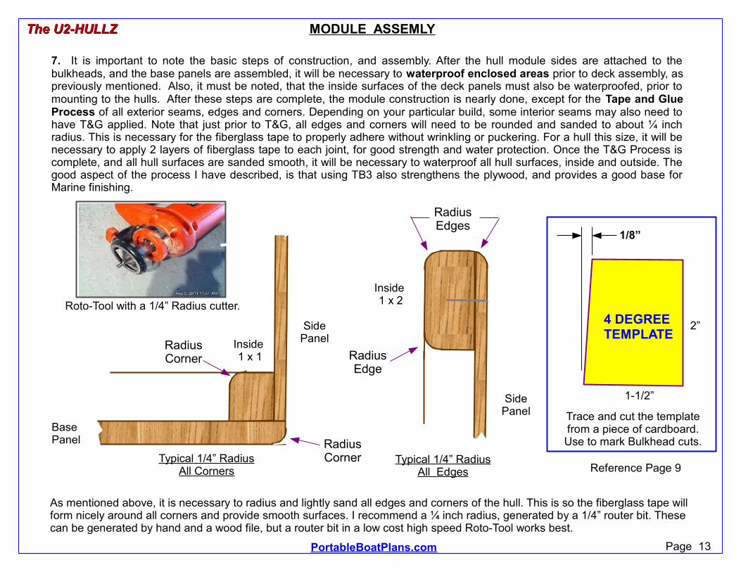
7. It is important to note the basic steps of construction, and assembly. After the hull module sides are attached to the bulkheads, and the base panels are assembled, it will be necessary to waterproof enclosed areas prior to deck assembly, as previously mentioned. Also, it must be noted, that the inside surfaces of the deck panels must also be waterproofed, prior to mounting to the hulls. After these steps are complete, the module construction is nearly done, except for the Tape and Glue Process of all exterior seams, edges and corners. Depending on your particular build, some interior seams may also need to have T&G applied. Note that just prior to T&G, all edges and corners will need to be rounded and sanded to about ¼ inch radius. This is necessary for the fiberglass tape to properly adhere without wrinkling or puckering. For a hull this size, it will be necessary to apply 2 layers of fiberglass tape to each joint, for good strength and water protection. Once the T&G Process is complete, and all hull surfaces are sanded smooth, it will be necessary to waterproof all hull surfaces, inside and outside. The good aspect of the process I have described, is that using TB3 also strengthens the plywood, and provides a good base for Marine finishing.
MODULE ASSEMLY
SidePanel
Inside 1 x 2
RadiusEdges
RadiusEdge
Typical 1/4” RadiusAll Edges
As mentioned above, it is necessary to radius and lightly sand all edges and corners of the hull. This is so the fiberglass tape will form nicely around all corners and provide smooth surfaces. I recommend a ¼ inch radius, generated by a 1/4” router bit. These can be generated by hand and a wood file, but a router bit in a low cost high speed Roto-Tool works best.
Roto-Tool with a 1/4” Radius cutter.
SidePanelInside
1 x 1
RadiusCornerTypical 1/4” Radius
All Corners
BasePanel
RadiusCorner
4 DEGREETEMPLATE
1-1/2”
2”
1/8”
Trace and cut the template from a piece of cardboard. Use to mark Bulkhead cuts.
Reference Page 9

The U2-HULLZThe U2-HULLZ FRONT MODULE ASSEMLY
Page 14PortableBoatPlans.com
Optional Temporary Spacer Bar
8. Normally, the Front Module would be constructed in exactly the same way as the Rear Module, and no further detail would be necessary. However, for the purpose of defining one of the hull options, the detail shown below will be of the Pointed Bow.
There are basically 3 steps to creating the pointed bow.
Cut 2 lengths of 1x2's and glue them together. Next, cut the ends to fit the Bow, as shown in Sketches 1 & 2, and glue and screw to the inside of one of the side panels. This is the Bow Block.
The next step is mounting of the side panels to the Center Bulkhead, just as you did for the Rear Module, Sketch 3..
The final step will be to bring both side panels together, glue and screw, as shown below in Sketch 4. This may require the use of a strap wrapped tightly around the outside length of the module, and a spacer bar, to hold the hull's desired shape.
Depending on where you want the Forward Bulkhead, the side shape can be enlarged slightly by wedging the bulkhead in place. Builders option.
Sketch 1 - Top View
Sketch 2 – Side View
Sketch 4 - Assembly
Remember, good side of plywood is on the outside of the hull.
The next step will be to add the Forward Bulkhead and the Internal 1x1 Edge Supports, but the process is more involved than was used on the Rear Module. See the next page for detail. After the bulkhead and supports are assembled, the Base Panel will be installed, in the same manner as the rear module, and any enclosed space will be waterproofed. Finally, the deck will be secured in position.
Bow Block
The nose will be rounded after the base assembly.
Note: The Bow Block could be made from 1x1 lumber, but more difficult to mount.
Sketch 3 - Mounting
1x1 Base and
Gunwale Supports
Drawings Not To Scale

The U2-HULLZThe U2-HULLZ FRONT MODULE ASSEMLY
Page 15PortableBoatPlans.com
9. After the module Pointed Bow is secure, it is time to consider what kind of Forward Bulkhead you will use to complete the Forward Module design. The bulkhead drawn is intended to keep the forward portion of the hull enclosed, and act as a safety buoyancy cell. With a removable port cover, it can also become a watertight dry storage area. However, the choice is yours. An option could be to have an upper and lower cross beam support, to maintain the hull shape and strength, and leave the forward portion wide open, for quick access to gear and equipment stored beneath the deck. The following sketches depict the enclosed version. It's important for you to note that the bulkhead can be placed almost anywhere, and at any angle. However, to allow good seating, it should be placed about 30 inches from the center bulkhead.
Once you have made this decision, placement of the kerffed side supports can begin. See the sketch directly below.
Approx. 30”
Forward Bulkhead
It bears repeating, if you are not building the Pointed Bow version, construct the Front Module just as you did the Rear Module.
10. The primary difference between the two versions is the curved side panels. In the straight version, 1x1 supports are easily cut and bonded to the bottom edges and the upper edges of the module, to which the base and deck are bonded. The same is required of the curved side panels, but the supports have to be “kerffed”, in order to bend to the rounded surfaces. Kerffing is the process of cutting saw blade width slots in the support, at equal intervals, to allow the support to conform to the shape of the side panels, and still provide panel strength. For this application, refer to the sketches below. It is important you do not cut through the support, and that the spacing is reasonably consistent. The supports are glued in place, and can be secured with screws or spring clamps, until cured.
Typical “KERF” saw cuts
3”
3/16”
This is the Kerf cut
by a hack saw blade on the 1x2 support.
Kerffed Supports
Optional 1x2 support
1x1 supports

The U2-HULLZThe U2-HULLZ FRONT MODULE ASSEMLY
Page 16PortableBoatPlans.com
Waterproof Forward Compartment – Page 17
1/2” Ply Base Panels
Note: If you decide to make the Rear base panels of a thicker material, you should also make the Forward base panels the same thickness.
11. Mark, cut and fit the base panels just as you did for the Rear Module assembly.
Depending on the Forward Bulkhead design chosen, you may have to Waterproof the forward compartment. Refer to the process on the next page.
ForwardCompartment
12. Now that you have completed the waterproofing of the forward compartment, it's time to install Deck Panels. I used the plural because we will do both modules at the same time. These are also “Fit at Assembly” panels, so they must be measured and cut to size. Again, depending on your build, the decks should at least enclose the Buoyancy Cells. Extending the forward deck is suggested for appearance and to minimize water intrusion. See deck examples on page 7. Remember, the inside of the deck panels must be waterproofed prior to installation. Another option is a forward module cuddy-cabin, for increased protection.
BuoyancyCell
Buo
yanc
yC
ell
Forward Deck Rear Deck
Once the decks are installed, it is important that all the edges have a radius applied, and all interior surfaces receive a light sanding. Then you can waterproof the inside of both modules, but only the inside. The next step, defined on page 18, is the Tape and Glue Process, page 18, of all the external seams and edges. As mentioned earlier, two layers of tape are necessary for this hull, so take your time and do a good job. Once the T&G is complete, and cured, other additions, such as 1x2 Gunwale Rub-Rails and Seat Supports, can be installed, as well as the 1x2 Skids on the bottom of the hull (page 26).

The U2-HULLZThe U2-HULLZ


All bulkheads and upright panels assembled. Relative position layout of the panels
Rear module bulkheads and side panel assembly Forward module bulkheads and side panel assembly
You should also notice the simple lines of the hull, all straight cuts, no curves. Improves the build time and reduces possible errors.
The U2-HULLZThe U2-HULLZ
Page 24PortableBoatPlans.com
These photos are from a different but similar build. Note the simplicity of construction, and ease of assembly.
PHOTO REVIEW
Pictures of the F.I.T., built by Greg Bowles, Ontario Canada.

The rear module fully assembled, with taped seams and edges. Note motor mount panel on transom.
The forward module, also completely taped. Note the addition of the deck with an access hatch opening.
Forward deck with twist-off hatch installed. Rear module bottom with epoxy and fiberglass covering.
The next steps will be the installation of the bottom skids, painting and accessories.
The U2-HULLZThe U2-HULLZ
Page 25PortableBoatPlans.com
PHOTO REVIEW

The U2-HULLZThe U2-HULLZ
Page 26PortableBoatPlans.com
If, for any reason, you do not wish to use the T&G Process for sealing all seams and edges, you can revert to the more traditional method of 1x1 inside corner stringers, as described in the sketch at right.
This can be more work, but will provide you with the necessary hull security desired. What it lacks is plywood edge sealing, which the T&G provides.
So, if you do employ the edge stringer method, I strongly suggest you at least fiberglass the outside seams, to prevent water penetration into the plywood.

Page 27PortableBoatPlans.com
The U2-HULLZThe U2-HULLZ
Optional 1x2 Rub RailsOptional Decking
STEP 13
On CenterBottom View
1x2 Skids
8”
Note: The skids are glued, and then screwed to the base from inside, using #8 x 1-1/4” flat head wood screws, stainless steel preferred. After the skids are complete it will be necessary to round all edges, and waterproof them.
The next step is to finally join the two hull modules together, using 3/8 inch diameter bolts. See the following pages.
The gunwale rub rails are a good addition for hull security and side rigidity. Some may want to add similar 1x1 rails along the water line, or chine area, for additional hull protection, prior to full hull waterproofing..
Shaded lines represent all T&G corners and edges.
In case you have forgotten, now is the time to completely WATERPROOF the entire inside and outside of the hull modules, page 17. Then sand lightly all
waterproofed surfaces in preparation for the final marine finishes.

The U2-HULLZThe U2-HULLZ
Page 28PortableBoatPlans.com
ASSEMBLY BOLT HOLES & HARDWARE
Assembly Bolt KnobSee drawing on next page.
Bolt length to be 3-1/2 inches
STEP 14

The U2-HULLZThe U2-HULLZ
Page 29PortableBoatPlans.com
STEP 15

The U2-HULLZThe U2-HULLZ
Page 30PortableBoatPlans.com
This is the point where you stand back and look at your creation, and decide what kind of finish to apply, and what colors. Just remember, the outside of the hull gets the most abuse, so select finishes that are marine rated, such as Marine Spar Varnish, like the boat shown below, or Marine Epoxy Paint. House paints are not recommended. Also, a heavy duty finish on the floor is recommended, to minimize wear. Some people use a spray-on truck bed-liner material. Again, your choice of materials and finishes is what makes your boat unique.
FINAL REVIEW
Finally, it is important to customize your boat to meet your specific needs and expectations. This can include anything from a full canopy top, to an internal raised platform for overnight sleeping. Fishing pole holders, like in the photo above, make for easy fishing while under power. One area of caution is not to place anything on the hull that would prevent nesting of the modules, or that could become damaged in transport. Good luck with your build, and make sure you practice safe boating.
The original goal of this particular design was to provide a hull that could be many things to many people. By constructing a boat that does what you want it to, rather than what the designer thinks you want, delivers a powerful message. Home builders often have dreams of the ideal boat, but most of the time have to make compromises, because their dream boat just does not exist. With this U2 Hullz concept, you can make it just the size, shape and function you desire. In retrospect, I think the goal has been achieved.
Sincerely,
Ken Simpson, Designer
Pictures of a similar boat, the F.I.T., built by Greg Bowles, Ontario Canada.