the unified modeling language (uml) instructor: jerry gao ph.d. san jose state university email:...
Post on 19-Dec-2015
213 views
TRANSCRIPT

The Unified Modeling Language (UML)
Instructor: Jerry Gao Ph.D.
San Jose State Universityemail: [email protected]
URL: http://www.engr.sjsu.edu/gaojerry
Sept., 2001

The Unified Modeling Language (UML)
- Introduction to UML
- An Overview of UML
- UML Notation
- Use-Case Modeling
- Modeling Classes, Objects, and Their Relationships - Dynamic Modeling
- Advanced Dynamic Modeling: Real-Time Systems
- Physical Architectures
Jerry Gao Ph.D. 9/2001
Presentation Outline
All Rights Reserved

Jerry Gao Ph.D. 9/2001
Introduction To UML
The Unified Modeling Language (UML)
What is UML?
The UML is a modeling tool (or methodology) for software engineers and system analysts.
It is designed to support all phases of software development, including
- Requirements analysis and specification- Software design specification- Software code generation- Testing systems and modules in a black box view
Why UML?- Software developments need consistent and standard modelingtool (or methods) to all phases of software development
>- understandable, consistent, simple, and powerful- Too many methods
Jerry Gao Ph.D. 9/2001
Introduction To UML
The Unified Modeling Language (UML)
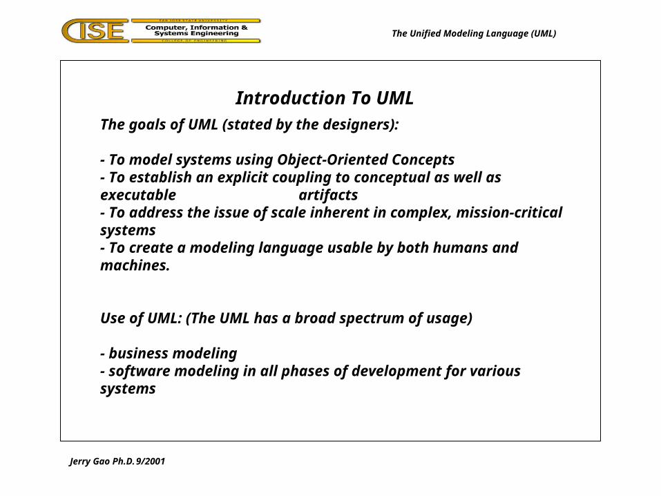
The goals of UML (stated by the designers):
- To model systems using Object-Oriented Concepts- To establish an explicit coupling to conceptual as well as executable
artifacts- To address the issue of scale inherent in complex, mission-critical systems - To create a modeling language usable by both humans and machines.
Use of UML: (The UML has a broad spectrum of usage)
- business modeling- software modeling in all phases of development for various systems

Jerry Gao Ph.D. 9/2001
Introduction To UML
The Unified Modeling Language (UML)
History of UML:
- Grady Booch and James Rumbaugh at Rational Software Corp.Started the work on UML in 1994. In the initial work, theyunite the Booch method and the MOT-2 method.
- In 1995 systems, Ivar Jacobson (OOSE and Objectory methods) joined them.
- Rational bought Objective System (the Swedish company)They started to work on UML to create a unified modeling method and tool

Jerry Gao Ph.D. 9/2001
Introduction To UML
The Unified Modeling Language (UML)
The Acceptance of UML:
- During 1996, a number of companies and organizations joinedRational to form the UML Partners consortium.
- 1997, many companies joined them:IBM, OCON, HP, DEC, Microsoft, Oracle, TI,….
- 1997 OMG has decide to use UML as their standard and is working on the final details of the specification.
Jerry Gao Ph.D. 9/2001
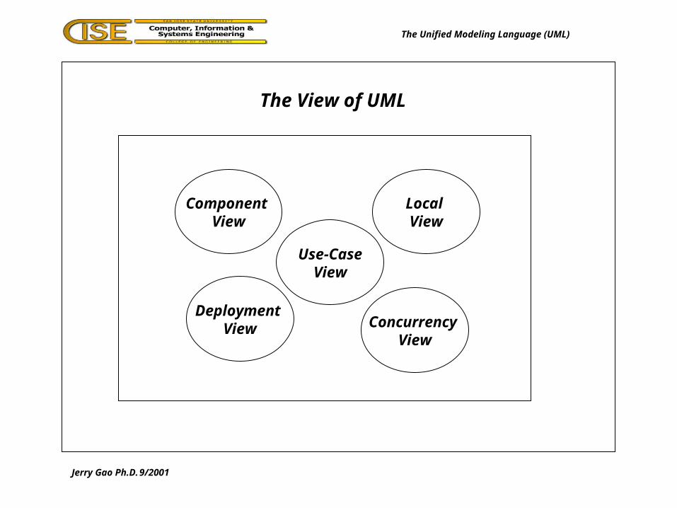
The View of UML
The Unified Modeling Language (UML)
Component View
Local View
Use-CaseView
Deployment View Concurrency
View

Jerry Gao Ph.D. 9/2001
An Overview of UML
The Unified Modeling Language (UML)
Software Application
System
Use-Case View:- Describe the functionality of the system from an external view- Focus on system function usage from the user point of view- Described in use-case diagrams- Used to support users, operators, designers, developers, and testers
External viewUse-CaseDiagrams
What are thesystem functions?

Jerry Gao Ph.D. 9/2001
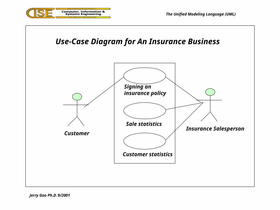
Use-Case Diagram for An Insurance Business
The Unified Modeling Language (UML)
Signing aninsurance policy
Sale statistics
Customer statistics
CustomerInsurance Salesperson
Jerry Gao Ph.D. 9/2001
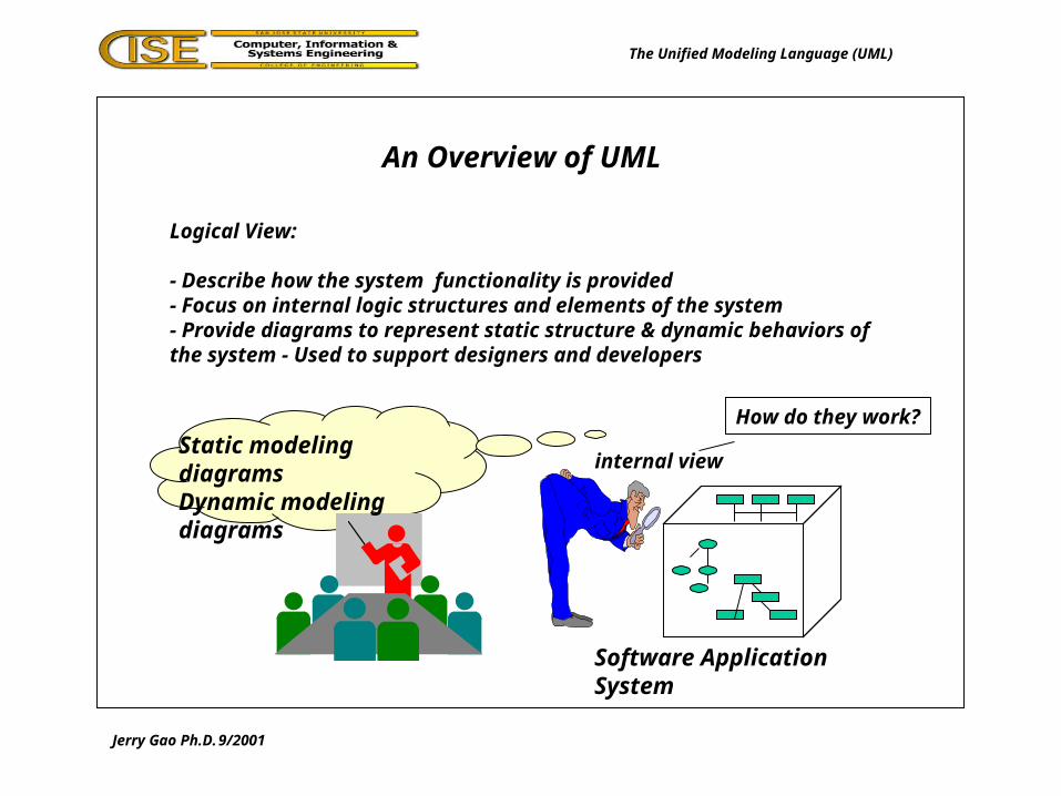
An Overview of UML
The Unified Modeling Language (UML)
Logical View:
- Describe how the system functionality is provided- Focus on internal logic structures and elements of the system- Provide diagrams to represent static structure & dynamic behaviors of the system - Used to support designers and developers
internal viewStatic modeling diagramsDynamic modeling diagrams
How do they work?
Software Application System

Jerry Gao Ph.D. 9/2001
A Class Diagram for Financial Trading
The Unified Modeling Language (UML)
Customer Portfolio Trader
Instrument
Bond Stock Stock Option
1 Owns 1..* 1..* Handles 1
0..*
0..*
Con
tain
sC
onta
ins

Jerry Gao Ph.D. 9/2001
A Class Diagram and An Object Diagram
The Unified Modeling Language (UML)
1..*
Author
Name:Stringage: integer
Computer
Name:Stringmemory: integer
Uses0..1Class diagram
Bob:Author
Name:”Bob J.”age: 32
Bob’s Job PCComputer
Name:”Dell 466”memory: 64
Object diagram

Jerry Gao Ph.D. 9/2001
A State Diagram for An Elevator
The Unified Modeling Language (UML)
On first floor
Movingup
MovingDown Idle
Moving tofirst floor
Go up(floor)
Active at floor
Go up(floor)
Arrive at floor
Go down(floor)
Arrive at first floor
Time out
Jerry Gao Ph.D. 9/2001
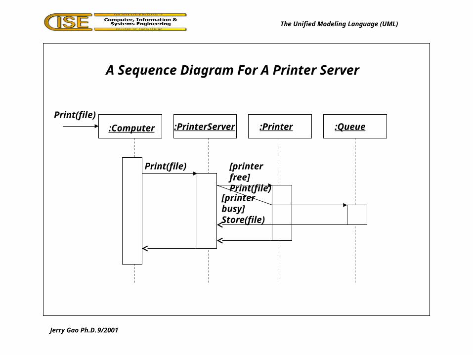
A Sequence Diagram For A Printer Server
The Unified Modeling Language (UML)
:Computer :PrinterServer :Printer :QueuePrint(file)
Print(file) [printer free]Print(file)
[printer busy]Store(file)

Jerry Gao Ph.D. 9/2001
A Collaboration Diagram For A Printer Server
The Unified Modeling Language (UML)
:Computer
:PrinterServer :Printer
:Queue
1:Print(file)
[printer busy]1.2:Store(file)
[printer free]1.1:Print(file)
Jerry Gao Ph.D. 9/2001
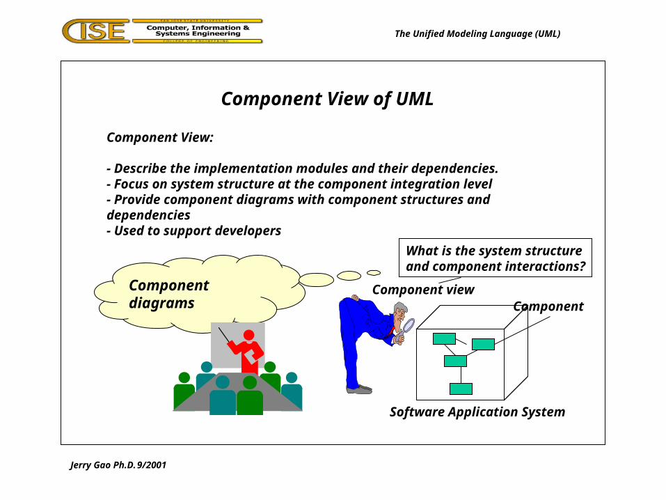
Component View of UML
The Unified Modeling Language (UML)
Component View:
- Describe the implementation modules and their dependencies.- Focus on system structure at the component integration level- Provide component diagrams with component structures and dependencies- Used to support developers
Component viewComponent diagrams
What is the system structureand component interactions?
Component
Software Application System

Jerry Gao Ph.D. 9/2001
An Activity Diagram Example
The Unified Modeling Language (UML)
PrintFile()
RemoveMessageBox Create
postscript file
Show MessageBox
“Print” onScreen
ShowMessageBox“Disk full”on Screen
[Disk full]
[free disk space]
^Printer.Print(file)

Jerry Gao Ph.D. 9/2001
A Component Diagram Example
The Unified Modeling Language (UML)
WindowHandler
(whnd.cpp)
CommHandler
(comhnd.cpp)
WindowHandler
(whnd.obj)
Graphic lib(graphic.dll)
MainClass
(main.cpp)
CommHandler
(comhnd.obj)
ClientProgram
(client.exe)
MainClass
(main.obj)

Jerry Gao Ph.D. 9/2001
An Overview of UML
The Unified Modeling Language (UML)
Concurrency View:
- View the system as processes and processors. - Focus on parallel execution, concurrent threads, their communications
and synchronization- Provide dynamic diagrams and implementation diagrams - Designed for developers and integrators of the system
Concurrency viewImplementation modeling diagramsDynamic modeling diagrams
What are processes?How do they interact?
Software Application System
P1
P3
P2
process

Jerry Gao Ph.D. 9/2001
An Overview of UML
The Unified Modeling Language (UML)
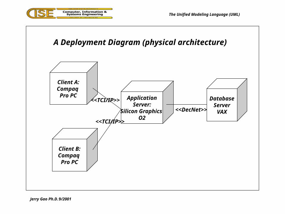
Deployment View:
- Describe show the physical deployment of the system (or physical architecture)in terms of devices and computers
- Focus on physical parts of the system and their connections- Provide deployment diagrams- Used to support developers, integrators, and testers
physical viewDeployment diagrams
What is the physical architecture?
Jerry Gao Ph.D. 9/2001
A Deployment Diagram (physical architecture)
The Unified Modeling Language (UML)
Client A:Compaq Pro PC
Client B:Compaq Pro PC
DatabaseServerVAX
ApplicationServer:
Silicon Graphics O2
<<TCI/IP>>
<<TCI/IP>>
<<DecNet>>

Jerry Gao Ph.D. 9/2001
UML Notation - Model Elements
The Unified Modeling Language (UML)
Class
Attributes
Operations
Object
Attributes
Operations
State
Node
Use caseInterface
Package ComponentNote

Jerry Gao Ph.D. 9/2001
UML Notation - Model Elements
The Unified Modeling Language (UML)
Aggregation
Dependency Association
Generalization
ClassanObject:
Class
Jerry Gao Ph.D. 9/2001
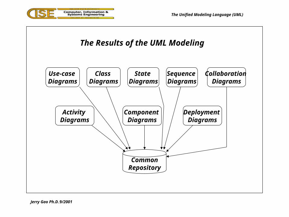
The Results of the UML Modeling
The Unified Modeling Language (UML)
Use-case Diagrams
Activity Diagrams
Sequence Diagrams
State Diagrams
Class Diagrams
Collaboration Diagrams
Component Diagrams
Deployment Diagrams
CommonRepository

Jerry Gao Ph.D. 9/2001
The UML: Use-Case Modeling
The Unified Modeling Language (UML)
Instructor: Jerry Gao Ph.D.
San Jose State Universityemail: [email protected]
URL: http://www.engr.sjsu.edu/gaojerry
Sept., 2001

Jerry Gao Ph.D. 9/2001
Use-Case Modeling
The Unified Modeling Language (UML)
Use-Case Modeling:- use the use-case diagrams to describe a system- represent the functionality of the system- present a use-case view of the system- an iterative process
The major components of a use-case model:- use cases, actors, and the system and relationships.
- The functionality is represented by a number of use cases. - Each of them specifies a complete functional feature.
Purpose of use cases:- to describe the functional requirements of the system- to provide a clear and consistent description of what the system do- to provide a basis for system tests- to make functional requirements traceable
Jerry Gao Ph.D. 9/2001
Use-Case Diagram for An Insurance Business
The Unified Modeling Language (UML)
Signing aninsurance policy
Sale statistics
Customer statistics
CustomerInsurance Salesperson
Jerry Gao Ph.D. 9/2001
Use-Case Modeling
The Unified Modeling Language (UML)
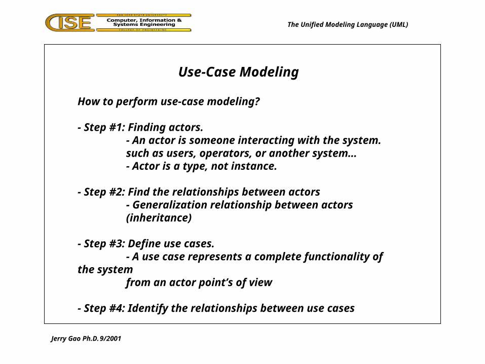
How to perform use-case modeling?
- Step #1: Finding actors.- An actor is someone interacting with the system.such as users, operators, or another system…- Actor is a type, not instance.
- Step #2: Find the relationships between actors- Generalization relationship between actors (inheritance)
- Step #3: Define use cases.- A use case represents a complete functionality of the systemfrom an actor point’s of view
- Step #4: Identify the relationships between use cases

Jerry Gao Ph.D. 9/2001
Use-Case Modeling
The Unified Modeling Language (UML)
Finding actors by asking the following questions:
- Who will use the system?
- Who will support and maintain the system?
- Who will perform administration work for the system?
- What other systems or (hardware) are interested the results from the system?
- What other systems or (hardware) may generate input information or signals to the system?

Jerry Gao Ph.D. 9/2001
Generalization between customer actors
The Unified Modeling Language (UML)
Customer
Telephone CustomerPersonal Visitor Customer

Jerry Gao Ph.D. 9/2001
Use-Case Modeling
The Unified Modeling Language (UML)
Characteristics of use cases:
- A use case is always initiated by an actor.- A use case provides value to an actor. - A use case is complete.- Use cases are connected to actors through associations.
Relationships between use cases:
- Extends relationship: one use case extends another use case by adding actions to a general use case.
- Use relationship: one use case uses another use case.
- Grouping:a number of use cases handle similar functionality.
Jerry Gao Ph.D. 9/2001
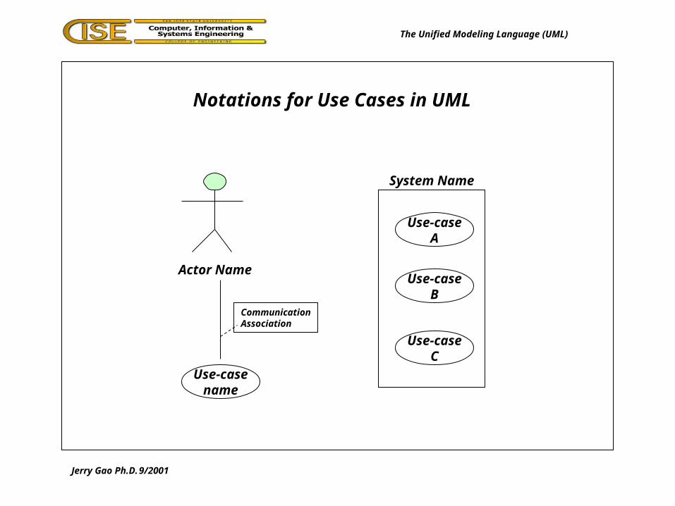
Notations for Use Cases in UML
The Unified Modeling Language (UML)
Actor Name
Use-casename
CommunicationAssociation
Use-caseA
Use-caseB
Use-caseC
System Name

Jerry Gao Ph.D. 9/2001
Relationships Between Use Cases in UML
The Unified Modeling Language (UML)
Signing insurance policy
Signing Car Purchase Insurance
<<Extends>>
Signing insurance policy
Signing Life Insurance
<<uses>>
Signing Car Insurance
<<uses>>
Jerry Gao Ph.D. 9/2001
Describing Use Cases
The Unified Modeling Language (UML)
The description of the use case is normally done through a text description. It also can be described through an activity diagram.
It is about how the actors and the use cases interact.The description of a use case should include:
- Objective for the use case
- How the use case is initiated
- The flow of messages between actors and the use case
- Alternative flow in the use case
- How the use case finishes with a value to the actor
Jerry Gao Ph.D. 9/2001
A Use Case Example
The Unified Modeling Language (UML)
Jerry Gao Ph.D. 9/2001
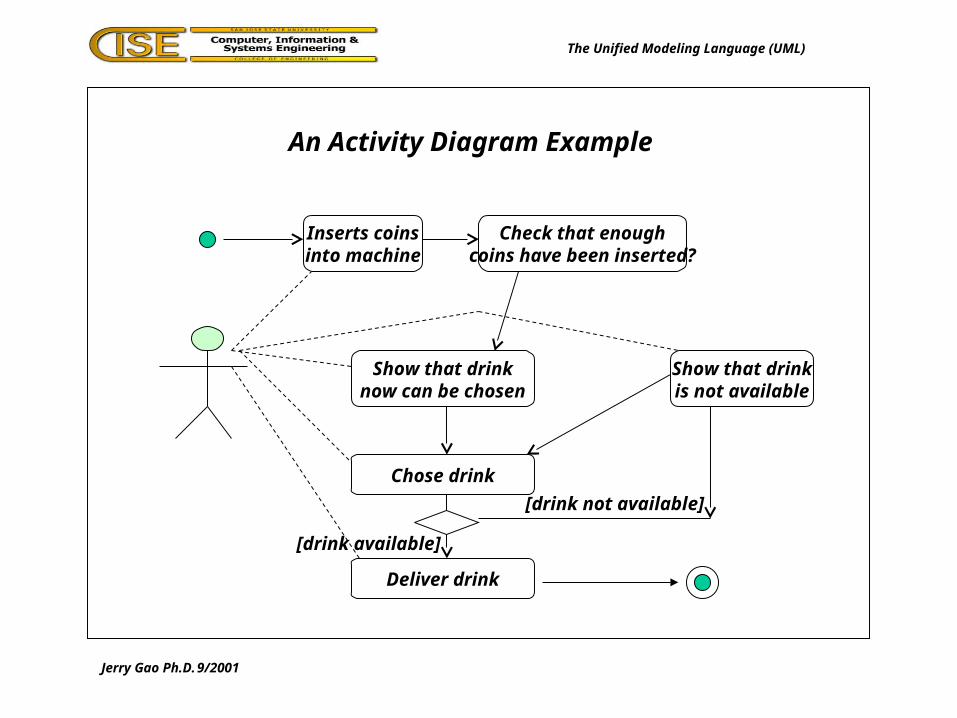
An Activity Diagram Example
The Unified Modeling Language (UML)
Inserts coinsinto machine
Check that enoughcoins have been inserted?
Show that drinknow can be chosen
Chose drink
Show that drinkis not available
Deliver drink
[drink available]
[drink not available]

Jerry Gao Ph.D. 9/2001
The UML: Object-Oriented Modeling
The Unified Modeling Language (UML)
Instructor: Jerry Gao Ph.D.
San Jose State Universityemail: [email protected]
URL: http://www.engr.sjsu.edu/gaojerry
Sept., 2001

Jerry Gao Ph.D. 9/2001
Object-Oriented Modeling
The Unified Modeling Language (UML)
Object-Oriented Modeling:- Focus on classes, objects and their relationships in the system- Represent the system using class diagrams and object diagrams- Is an iterative process
The major elements of the object-oriented modeling:- classes, objects and their relationships.
Purpose of object-oriented modeling:- to describe the system in terms of classes and objects- to provide a complete object-oriented view of the system - to help the understanding of the system through object-oriented analysis and modeling

Jerry Gao Ph.D. 9/2001
A Class Diagram and An Object Diagram
The Unified Modeling Language (UML)
1..*
Author
Name:Stringage: integer
Computer
Name:Stringmemory: integer
Uses0..1Class diagram
Bob:Author
Name:”Bob J.”age: 32
Bob’s Job PCComputer
Name:”Dell 466”memory: 64
Object diagram

Jerry Gao Ph.D. 9/2001
Object-Oriented Modeling
The Unified Modeling Language (UML)
How to perform object-oriented modeling?
- Step #1: Identify classes and objects in the system.- Find classes in the system- Identify their names and attributes- Identify their operations or functions
- Step #2: Find the relationships between classes- Find association relationships between classes- Find aggregation relationships between classes- Find inheritance (generalization) relationship between classes- Define the roles and cardinality of each class in the relationships.
- Step #3: Generate object diagrams based class diagrams

Jerry Gao Ph.D. 9/2001
Finding Classes
The Unified Modeling Language (UML)
Finding classes by asking the following questions:
- Do we have information that should be stored or analyzed?If so, check information-oriented classes. such as input/output
- Do we have external systems? If so, check the interface classes.
- Do we use any components, libraries? If so, check component-orientedclasses and library-oriented classes.
- Do we have any customers or users? If so, check user-oriented classes.
- Do we handle any devices? If so, check hardware-oriented interface classes.
- Do we have any business structure or organization involved in the system? If so, find organization-oriented classes.

Jerry Gao Ph.D. 9/2001
Class Examples
The Unified Modeling Language (UML)
Student
Name:Stringage: integerSS#: StringGPA: float
ReadStudent();UpdateStudent();CreateStudent();PrintStudent();
Figure
Size: Sizeposition: PositionType: FigureType
draw();setFiguer();scaleFigure();returnPosition();
operations
attributes
Jerry Gao Ph.D. 9/2001
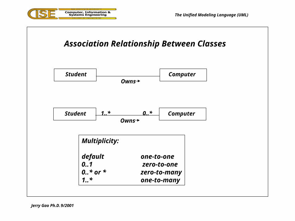
Association Relationship Between Classes
The Unified Modeling Language (UML)
Student ComputerOwns
Student ComputerOwns
1..* 0..*
Multiplicity:
default one-to-one0..1 zero-to-one0..* or * zero-to-many1..* one-to-many
Jerry Gao Ph.D. 9/2001
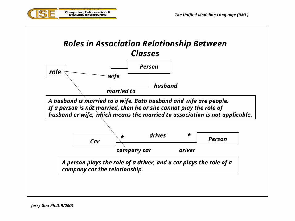
Roles in Association Relationship Between Classes
The Unified Modeling Language (UML)
Person
married to
wife
husband
A husband is married to a wife. Both husband and wife are people.If a person is not married, then he or she cannot play the role of husband or wife, which means the married to association is not applicable.
Car Persondrives* *
company car driver
role
A person plays the role of a driver, and a car plays the role of a company car the relationship.

Jerry Gao Ph.D. 9/2001
Aggregation Relationship Between Classes
The Unified Modeling Language (UML)
Navy WarshipContains
Team Personmembers
* *
** Normal Aggregation
Shared Aggregation
A team is composed of team members. One person could be a member of many teams.
Jerry Gao Ph.D. 9/2001
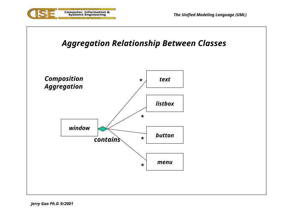
Aggregation Relationship Between Classes
The Unified Modeling Language (UML)
Composition Aggregation
window
listbox
text
button
menu
*
*
*
*
contains

Jerry Gao Ph.D. 9/2001
Generalization Relationship Between Classes
The Unified Modeling Language (UML)
Normal Generalization -> Inheritance
Part-timeStudent
Student
Full-timeStudent
Part-timeStudent
Student
Full-timeStudent

Jerry Gao Ph.D. 9/2001
A Class Diagram for Financial Trading
The Unified Modeling Language (UML)
Customer Portfolio Trader
Instrument
Bond Stock Stock Option
1 Owns 1..* 1..* Handles 1
0..*
0..*
Con
tain
sC
onta
ins

Jerry Gao Ph.D. 9/2001
Packages
The Unified Modeling Language (UML)
Subsystem B
Subsystem A
Subsystem E
Subsystem C
Subsystem D
dependency
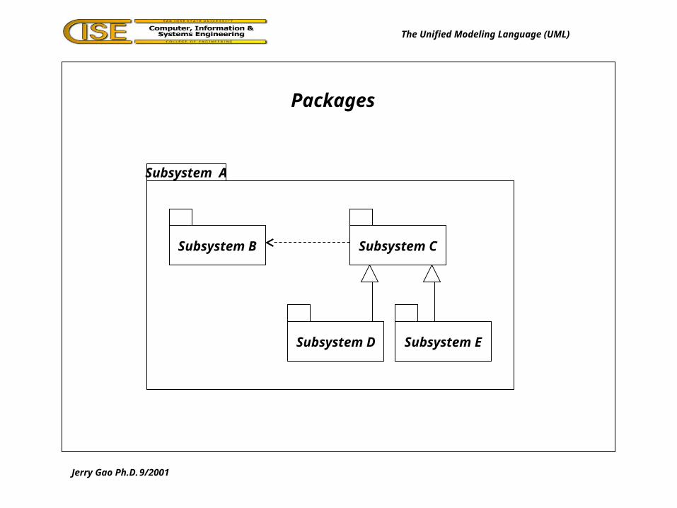
Jerry Gao Ph.D. 9/2001
Packages
The Unified Modeling Language (UML)
Subsystem B
Subsystem A
Subsystem D
Subsystem C
Subsystem E
Jerry Gao Ph.D. 9/2001
The UML: Dynamic Modeling
The Unified Modeling Language (UML)
Instructor: Jerry Gao Ph.D.
San Jose State Universityemail: [email protected]
URL: http://www.engr.sjsu.edu/gaojerry
Sept., 2001

Jerry Gao Ph.D. 9/2001
Dynamic Modeling
The Unified Modeling Language (UML)
Dynamic Modeling:- Focus on dynamic behaviors in the system- Use state, sequence, collaboration, and activity diagramsto present the behaviors of the system- Demonstrate how the objects interact dynamically
The results of dynamic modeling:
- State diagrams: -> describing object states and their changes in terms of events.
- Sequence diagrams:-> describing how objects interact and communicate with each other.
- Collaboration diagrams:-> describing how objects collaborate together by interactions
- Activity diagrams: -> another shows the object interactions for functionality and actors.

Jerry Gao Ph.D. 9/2001
The Notation of State Diagram
The Unified Modeling Language (UML)
State 1 State 2Event
State
starting point
State
end point
State Name
State Vars
Activities
Jerry Gao Ph.D. 9/2001
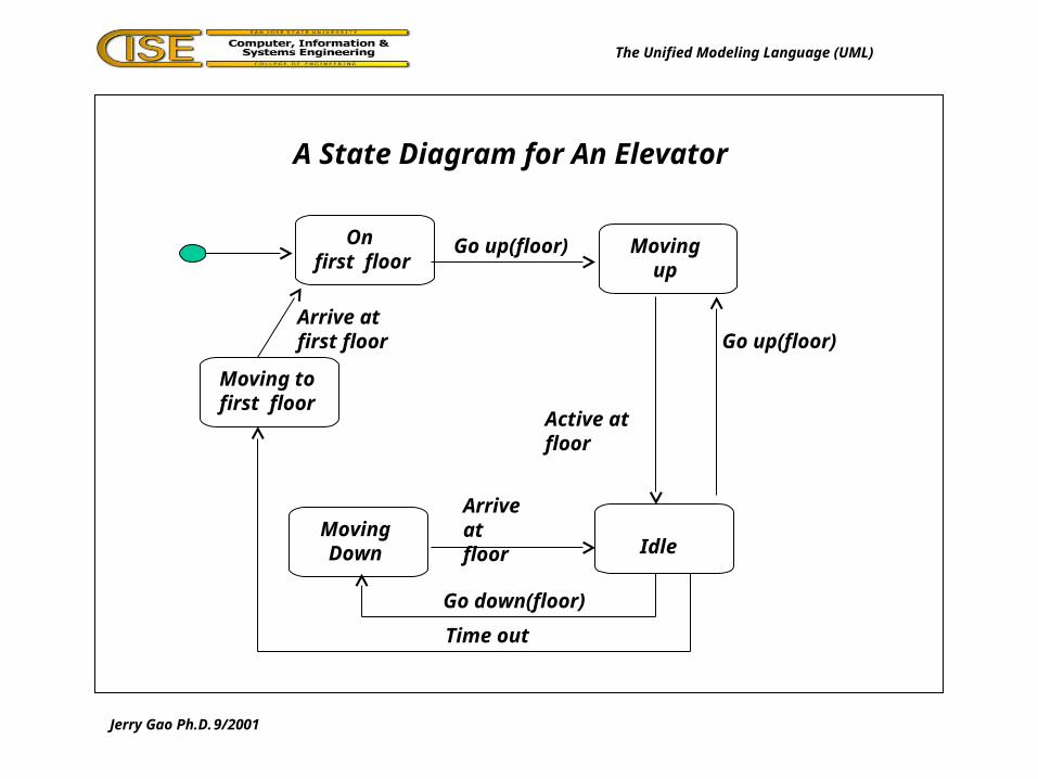
A State Diagram for An Elevator
The Unified Modeling Language (UML)
On first floor
Movingup
MovingDown Idle
Moving tofirst floor
Go up(floor)
Active at floor
Go up(floor)
Arrive at floor
Go down(floor)
Arrive at first floor
Time out

Jerry Gao Ph.D. 9/2001
A State Diagram for An Elevator
The Unified Modeling Language (UML)
On first floor
Moving up
do/moving to floor
Moving down
do/moving to floor
Idletimer = 0
do/increase timer
Moving tofirst floor
Go up(floor)Active at floor
Go up(floor)
Arrive at floor
Go down(floor)
Arrive at first floor
[Timer = time out] Guard-condition

Dynamic Modeling
Instructor: Jerry Gao Ph.D.
San Jose State Universityemail: [email protected]
URL: http://www.engr.sjsu.edu/gaojerry
Sept., 2001

Topic: The Unified Modeling Language
Jerry Gao Ph.D. 9/2001
Sending Messages between State Diagrams
All Rights Reserved
Off On
On()
Off()
Play()Stop()
Off On/Stop
On()
Off()
Off()/Stop()
On/Play
Play()
Stop()
CD PlayerStop()Play()On() Off()
Remote control

Topic: The Unified Modeling Language
Jerry Gao Ph.D. 9/2001 All Rights Reserved
An And-Substates Example
Low Speed High Speed
Forward Backward
Running
concurrent substates

Sequence Diagram
Instructor: Jerry Gao Ph.D.
San Jose State Universityemail: [email protected]
URL: http://www.engr.sjsu.edu/gaojerry
Sept., 2001
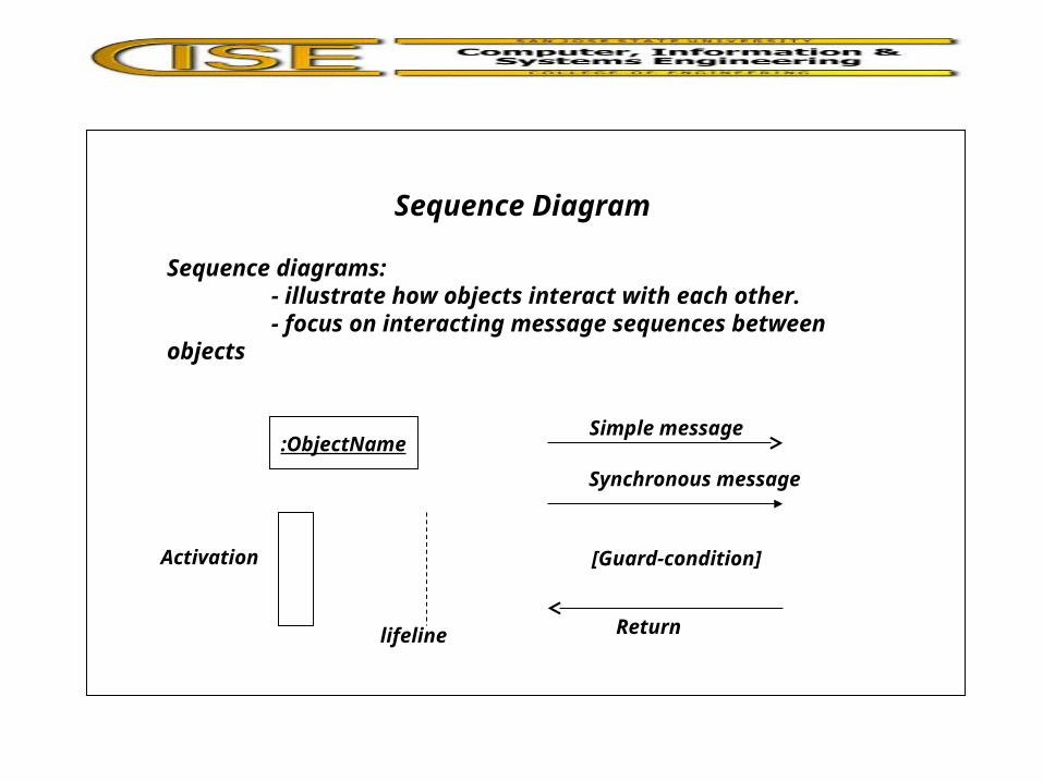
Sequence Diagram
Sequence diagrams:- illustrate how objects interact with each other.- focus on interacting message sequences between objects
:ObjectNameSimple message
Synchronous message
[Guard-condition]
Return
Activation
lifeline

Sequence Diagram Example
:Computer
Print(ps-file)
Activation
lifeline
:PrinterServer :Printer
Print(ps-file)
Object[no queue]Print(ps-file)
Guard-condition
Synchronousmessage
Return
simplemessage

Sequence Diagram Example
:Computer
Print(file)
:PrinterServer :Printer
Print(file)
[printer free]Print(file)
:Queue
[printer busy]Store(file)
Collaboration Diagram
Instructor: Jerry Gao Ph.D.
San Jose State Universityemail: [email protected]
URL: http://www.engr.sjsu.edu/gaojerry
Sept., 2001

Collaboration Diagram
Collaboration diagrams:- illustrate the interactions of objects.- focus on space instead of time.
Applications:- may be used to show the execution of an operation- may be used to show a use-case execution- simply an interaction scenario in the system
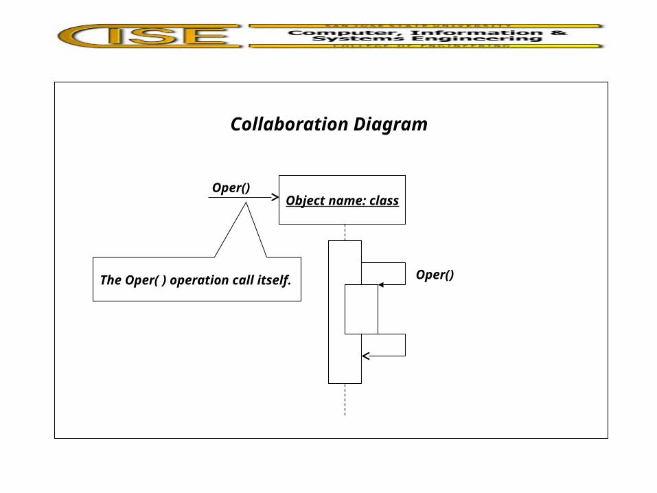
Collaboration Diagram
Object name: classOper()
Oper()The Oper( ) operation call itself.

Sequence Diagram Example
:Computer
:PrinterServer :Printer
Print(ps-file)
1:Print(ps-file)
[printer free] 1.1:Print(ps-file)

Collaboration Diagram Example
:MainWindow :Customer{new}
:CustomerWindow{transient}
NewCustomer()
2:Create()
[free memory] 1:Create()
3:Show(Customer)
3:Update(data)
{parameter}
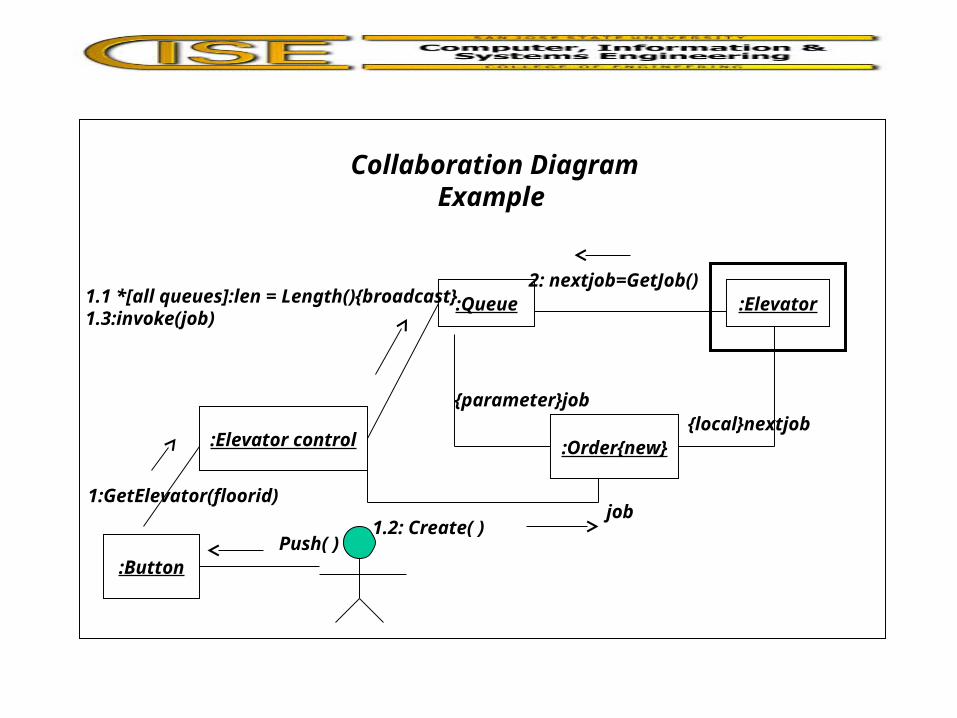
Collaboration Diagram Example
:Queue :Elevator
:Order{new}
{parameter}job
2: nextjob=GetJob()
{local}nextjob:Elevator control
1.1 *[all queues]:len = Length(){broadcast}1.3:invoke(job)
:Button
1.2: Create( )Push( )
1:GetElevator(floorid)job

Activity Diagram
Instructor: Jerry Gao Ph.D.
San Jose State Universityemail: [email protected]
URL: http://www.engr.sjsu.edu/gaojerry
Sept., 2001

Activity Diagram
Activity diagrams:- focus on work performed in the implementation of an operation and activities in a use-case instance or in an object- capture actions and results in terms of object state changes.
Activity diagrams are used for different purposes:- to capture the work that will be performed when an operation is executing.- to capture the internal work in an object.- to show how a set of related actions may be performed, and how they will affect objects around them.- to show an instance of a use-case may be performed in termsof actions and object state changes.- to show how a business works in terms of workers, workflows,organization, and objects.

Activity Diagram Example - Show a sequence of interactions
Show MessageBox“Printing” on screen
Create postscript file
Remove MessageBox Send postscriptfile to printer
CustomerWindow.PrinterAllCustomers()

Activity Diagram Example - Show a sequence of interactions
Show MessageBox“Printing” on screen
Create postscript file
Remove MessageBox
^Printer.Printer(file)
CustomerWindow.PrinterAllCustomers()
Send-clause

Activity Diagram Example - Show a sequence of interactions
Show MessageBox“Printing” on screen
Show MessageBox“Disk full” on thescreen
Remove MessageBox
CustomerWindow.PrinterAllCustomers()
Create postscript file
[disk full]
[free disk space]
^Printer.Printer(file)
Send-clause
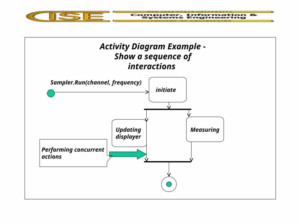
Activity Diagram Example - Show a sequence of interactions
initiate
MeasuringUpdatingdisplayer
Sampler.Run(channel, frequency)
Performing concurrent actions